Modular telecontrol system I/O expansion modules - EES Elektra ...
Modular telecontrol system I/O expansion modules - EES Elektra ...
Modular telecontrol system I/O expansion modules - EES Elektra ...

Create successful ePaper yourself
Turn your PDF publications into a flip-book with our unique Google optimized e-Paper software.
09.03.2011<br />
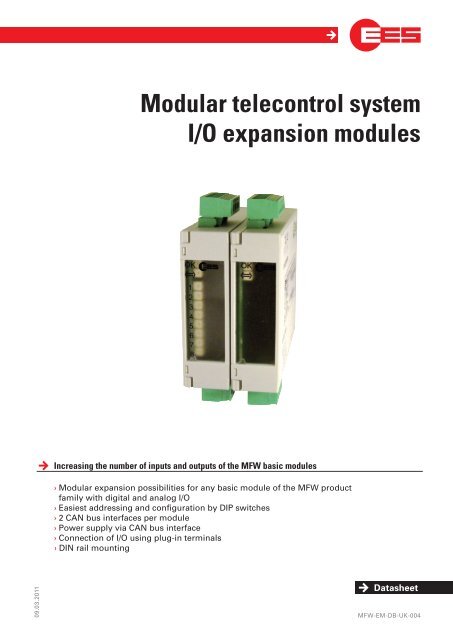
<strong>Modular</strong> <strong>telecontrol</strong> <strong>system</strong><br />
I/O <strong>expansion</strong> <strong>modules</strong><br />
Increasing the number of inputs and outputs of the MFW basic <strong>modules</strong><br />
› <strong>Modular</strong> <strong>expansion</strong> possibilities for any basic module of the MFW product<br />
family with digital and analog I/O<br />
› Easiest addressing and configuration by DIP switches<br />
› 2 CAN bus interfaces per module<br />
› Power supply via CAN bus interface<br />
› Connection of I/O using plug-in terminals<br />
› DIN rail mounting<br />
Datasheet<br />
MFW-EM-DB-UK-004
moDular <strong>telecontrol</strong> <strong>system</strong><br />
Functional description<br />
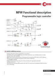
The extension of the amount of analog and digital I/Os of the MFW basic module is possible with the aid of the <strong>expansion</strong><br />
<strong>modules</strong>. The connection is done by using the bus cable , which is in the scope of supply on one of the two CAN-bus sockets.<br />
The second socket is usable for the connection of another module or for test purposes.<br />
The power of the <strong>modules</strong> is supplied over the CAN-bus. The configuration of the <strong>modules</strong> is done simply by the DIP<br />
switch.<br />
analog <strong>modules</strong><br />
The analog <strong>modules</strong> are available as input or output<br />
components.<br />
The input <strong>modules</strong> contain 4 analog inputs, that have a common<br />
GND. The inputs are electrically isolated from the power supply.<br />
Each input can be switched between current and voltage by DIP<br />
switch (0 ... 20 mA or 0...10 V).<br />
The output <strong>modules</strong> include 4 short-circuit proof analog current<br />
and voltage outputs (0 ... 20 mA or 0...10 V),<br />
for which no auxiliary voltage is required.<br />
page 2 of 8<br />
The common GND is equipotential with the power<br />
supply.<br />
The connection of 4 ... 20 mA sensors is also possible,<br />
because the analog values are not alternated<br />
while transmission and therefore also failure states<br />
can be displayed.<br />
Analog input module<br />
Analog output module<br />
Attention:<br />
common GND of the<br />
inputs!<br />
Attention:<br />
common GND of the<br />
outputs!
i/o <strong>expansion</strong> moDules<br />
Digital inputs<br />
Digital input <strong>modules</strong> are available in two different variants:<br />
• Digital input module (Standard)<br />
• Pulse-input module (All Inputs are switchable in common between static / pulses)<br />
The 8 inputs of the module are configurable per DIP-switch to one of the following input types:<br />
Binary input static<br />
Except for logged values the actual state of the inputs is acquired and transmitted on every data exchange. To transmit a<br />
change of state safely, the state has to line up at least until it is being transmitted. With dial-up <strong>system</strong>s it means that the<br />
state must not change while a transmission is being on-going.<br />
Pulse input<br />
For transmission of short pulses the first 4 inputs can be configured for safe pulse transmission. Per DIP-switch two<br />
counting frequencies and corresponding pulse lengths can be adjusted. With the pulse input module „EM-G8DEX-0-BB-<br />
E“ all 8 inputs can be configured together as static binary inputs or pulse inputs.<br />
Inverted inputs<br />
With the inverted input module „EM-G8DEX-0-BB-E“ single inputs can be inverted.<br />
The signals at these inputs are inverted before transmission and displayed through the red operation LED’s.<br />
Operating hour meter<br />
The inputs DE1 and DE2 of the standard input <strong>modules</strong> „EM-G8DEX-0-BB-0“ can be used as operating hour meters. The<br />
detected operating hours are stored as counter values. The significance of pulses is parameterisable with 0,1 h respectively<br />
1 h. The output of an input configured as operating hour meter can be done as a counter value (Operating hours)<br />
and / or as a binary value (Operation state).<br />
EM-G8DEX<br />
Signal<br />
voltage<br />
Signal<br />
voltage<br />
Terminal assignment: Module with 8 digital inputs<br />
The 8 inputs are realised in 2 groups of 4 inputs with a<br />
common root. The 2 inputs groups are potentionally isolated<br />
against each other.<br />
page 3 of 8
moDular <strong>telecontrol</strong> <strong>system</strong><br />
relays output module<br />
Relay output <strong>modules</strong> consist of 8 output relays. These can be used as static binary outputs or pulse outputs. By DIP-switch<br />
the outputs A1…A4 can optionally be switched between binary static output or counter value output. In combination<br />
with a pulse input module or a master device unit with IEC 60870-5-101/104 interface (output of a pulsed commands) all<br />
outputs of the <strong>expansion</strong> module are configurable as pulsed outputs. The output frequency (pulse width / -pause) is also<br />
possible to adapt via DIP-switch to the inputs of a further processing <strong>system</strong>.<br />
page 4 of 8<br />
Applications which have frequent switching processes<br />
(e.g. counter), we recommend using transistor <strong>modules</strong>,<br />
because the lifetime of relays is electrically and mechanically<br />
limited.<br />
There are 2 groups each of 4 inputs or outputs with a common<br />
root that are electrically isolated from one another.<br />
transistor output module<br />
All 8 transistor outputs switch against the common<br />
GND (Terminal „C“).<br />
Terminal assignment of the relay module<br />
Transistor-output <strong>modules</strong> consist of 8 Transistor outputs. These can be used as static binary outputs or pulse outputs. Per<br />
DIP-switch the outputs A1 ... A4 are switchable between the operation modes binary static output or counter value output.<br />
In combination with a pulse input module or a master device unit with IEC 60870-5-101/104 interface (output of a pulsed<br />
commands) all outputs of the <strong>expansion</strong> module are configurable as pulsed outputs. The output frequency (pulse width /<br />
-pause) is also possible to adapt via DIP-switch to the inputs of a further processing <strong>system</strong>.<br />
Attention:<br />
Possitive switched PNP transistors!<br />
Terminal assignment of the transistor output module
i/o <strong>expansion</strong> moDules<br />
object protection module<br />
The object-protection module is based on the hardware of a digital input module. Mechanical and electrical data are<br />
identically. However the function given in the following is realised.<br />
Input 1 … 4 E1…E4 optional as binary- or counted measurand (adjustable via DIP-switch )<br />
Input 5 binary input<br />
Input 6 acknowledgement / inspection<br />
Input 7 alarm input 1<br />
Input 8 alarm input 2<br />
Alarm input<br />
deactivated<br />
leaVinG<br />
Facility<br />
alarm delay<br />
time<br />
Delay<br />
expired<br />
Acknowledgement<br />
activated<br />
Acknowledgement<br />
deactivated<br />
Facility is<br />
unmanneD<br />
inspection<br />
authorised<br />
access<br />
Acknowledgement<br />
activated<br />
alarm<br />
Alarm input<br />
triggered<br />
Acknowledgement<br />
activated<br />
Status diagram of the object protection functionality<br />
Facility<br />
entereD<br />
alarm delay<br />
time<br />
Delay<br />
expired<br />
The inputs E7 and E8 serve as alarm inputs ( e.g. a<br />
door contact or a movement detector ) in which the<br />
alarm input 2 (E8) operation mode can be adjusted<br />
per DIP-switch “B8” between operating (NO) and<br />
closed-circuit current (NC).<br />
By a key switch attached to the input E6 (acknowledgement<br />
/ inspection) the authorized inspection<br />
of the object can be signaled.<br />
By activation of one of the two alarm inputs the<br />
status „FACILITY ENTERED“ is triggered and the<br />
message „object entered“ (E7) is generated. The<br />
alarm delay is running. Within the alarm delay<br />
time the status „INSPECTION“ can be achieved by<br />
actuating acknowledgement. If the acknowledgement<br />
does not occur, the plant switches to the<br />
status „ALARM“ after the expiration of the alarm<br />
delay time.<br />
The message “Alarm / buglary “ (E8) is being triggered.<br />
After leaving the facility by deactivation of the acknowledgement the status „LEAVING FACILITY” is engaged. Is the alarm<br />
input deactivated within the arming delay time, the plant engages the status “FACILITY IS UNMANNED “. The message<br />
“Facility entered” is deleted. If the alarm input is not deactivated during the arming delay time, the plant switches to the<br />
status “ALARM”. The message “Alarm / buglary “ (E8) is being triggered.<br />
page 5 of 8
moDular <strong>telecontrol</strong> <strong>system</strong><br />
technical data<br />
General Data<br />
Operating and ambient temperature -20 °C ... +60 °C<br />
Air humidity maximum 95 %, non-condensing<br />
Connection terminals pluggable<br />
Cross wire section rigid or flexible<br />
without wire sleeves 0,2 ... 2,5 mm 2<br />
with wire sleeves 0,25 ... 2,5 mm 2<br />
Assembly on C-DIN rail TS35 acc. to EN60715:2001-09<br />
Housing / protection class plastic / IP 40<br />
Digital input module<br />
Power consumption max. 1 W<br />
Input variant 8 digital inputs<br />
Signal voltage U S see table<br />
Input resistance U S see table<br />
Max. counting frequency switchable between 5 Hz or 80 Hz * 1<br />
Min. pulse width / pause 500 ms or 50 ms * 1<br />
Electrical isolation between<br />
signal and supply voltage 4 kV eff<br />
Transistor output module<br />
Type of transistor outputs plusswitching PNP-transistors<br />
Power consumption max. 2 W logic + load current<br />
Load capacity at transistor outputs max. 50 mA per output<br />
Max. count rate switchable between 1 Hz or 10 Hz * 1<br />
Min. pulse width / pause 500 ms or 50 ms * 1<br />
Relay output module<br />
Power consumption max. 3 W<br />
Contact type of relay outputs 8 x NO<br />
Contact loading of the relay outputs* 2<br />
minimum 1.2 V / 1 mA (suitable for control of LED)<br />
maximum 250 V AC / 400 mA<br />
250 V AC / 2 A (purely ohmic load)<br />
30 V DC / 2 A<br />
110 V DC / 0.2 A<br />
220 V DC / 0.1 A<br />
total 230V AC current 8 A (purely ohmic load)<br />
Maximum count rate switchable between 1 Hz or 10 Hz * 1<br />
Min. pulse width / pause 500 ms or 50 ms * 1<br />
Electrical isolation between<br />
relay contacts and power supply 4 kV eff<br />
Analog input <strong>modules</strong><br />
Power consumption max. 2 W<br />
Input type 4 analog inputs (0 ... 10 V or 0 ... 20 mA)<br />
Resolution 12 bit<br />
Accuracy less than 0.25 % of final value / 1 year * 3<br />
Input current load 100 Ω<br />
Input resistance at voltage input 100 kΩ<br />
page 6 of 8
proDuktbezeichnunG<br />
i/o <strong>expansion</strong> moDules<br />
technical data<br />
Analog output <strong>modules</strong><br />
Power consumption max. 3,5 W<br />
Input type 4 analog outputs (0 ... 10 V or 0 ... 20 mA)<br />
Resolution 12 Bit<br />
Accuracy less than 0.5 % of final value / 1 year * 3<br />
Max. burden output current load 500 Ω<br />
Minimum impedance of voltage output 1 kΩ<br />
Object-protection module<br />
Power consumption max. 1 W<br />
Signal voltage U S see table<br />
Input resistance see table<br />
Max. counting frequency 5 Hz * 1<br />
Min. pulse width / pause 100 ms * 1<br />
Alarm delay time 0 s ... 4 min (adjustable via DIP-switch)<br />
Alert on-delay time alarm delay time + 30 s<br />
Electrical isolation between<br />
signal and supply voltage 4 kV eff<br />
Digital input <strong>modules</strong> are available with various signal voltages U S . The corresponding voltage is defined by the 13th digit<br />
of the type identification, e.g. EM-G8DEX-0-BA-0.<br />
Signalvoltage US A B<br />
Voltage key<br />
E F U<br />
Nominal voltage 12 V AC/DC 24 V AC/DC 60 V AC/DC 110 V AC/DC 220 V AC/DC<br />
Maximum input voltage 24 V 48 V 75 V 130 V 255 V<br />
Input voltage DC<br />
maximum low state<br />
minimum high state<br />
Input voltage AC<br />
maximum low state<br />
minimum high state<br />
5,0 V DC<br />
7,5 V DC<br />
9,5 V DC<br />
14,5 V DC<br />
12,5 V DC<br />
19,5 V DC<br />
22,0 V DC<br />
35,0 V DC<br />
58,0 V DC<br />
92,0 V DC<br />
3,5 V AC 6,5 V AC 9,0 V AC 15,0 V AC 40,0 V AC<br />
10,0 V AC 19,0 V AC 25,0 V AC 45,0 V AC 120,0 V AC<br />
Input resistance approx. 5 kΩ 10 kΩ 22 kΩ 68 kΩ 180 kΩ<br />
Available signal voltage of digital input <strong>modules</strong><br />
We recommend not to run pulse inputs with alternating voltage, but only with direct voltage.<br />
If not otherwise noted, the given information for alternating voltage are refering to a sinusoidal alternating<br />
voltage with a frequency of 50/60 Hz and an ambient temperature of 25 °C.<br />
* 1 Other values on request<br />
* 2 We would be happy to supply you with more precise specifications on request.<br />
* 3 For greatest accuracy an annual calibration service is available.<br />
page 7 of 8
i/o <strong>expansion</strong> moDules<br />
Dimensional drawing<br />
order identification<br />
Item number Type Description<br />
97AXXGAX0BA0 EM-G8DEX-0-BA-0 8 DI, signal voltage 12 V<br />
97AXXGAX0BB0 EM-G8DEX-0-BB-0 8 DI, signal voltage 24 V<br />
97AXXGAX0BE0 EM-G8DEX-0-BE-0 8 DI, signal voltage 60 V<br />
97AXXGAX0BF0 EM-G8DEX-0-BF-0 8 DI, signal voltage 110 V<br />
97AXXGAX0BU0 EM-G8DEX-0-BU-0 8 DI, signal voltage 220 V<br />
97AXXGAX0BBE EM-G8DEX-0-BB-E 8 DI (static/pulse), signal voltage 24 V<br />
97AXXGBX0BB0 EM-G8DAL-0-BB-0 8 Transistor outputs<br />
97AXXGCX0BX0 EM-G8DAR-0-BX-0 8 Relay outputs<br />
97AXXGEX0BX0 EM-G4AE0-0-BX-0 4 analog outputs 0 ... 20 mA or 0...10 V<br />
97AXXGIX0BX0 EM-G4AA0-0-BX-0 4 analog outputs 0 ... 20 mA or 0...10 V<br />
97AXXGAX0BB2 EM-G8DEX-0-BB-2 Object-protection module, 8 DI, signal voltage 24 V<br />
kontakt contact<br />
<strong>Elektra</strong> Elektronik GmbH & Co Störcontroller KG | Hummelbühl 7-9 | 71522 Backnang | Germany<br />
Tel. +49 (0) 7191.182-0 | Fax. +49 (0) 7191.182-200 | info@ees-online.de | www.ees-online.de<br />
Dimensions in mm<br />
The right to make technical changes is reserved