Managing the Information Systems Project - Prentice Hall
Managing the Information Systems Project - Prentice Hall
Managing the Information Systems Project - Prentice Hall

You also want an ePaper? Increase the reach of your titles
YUMPU automatically turns print PDFs into web optimized ePapers that Google loves.
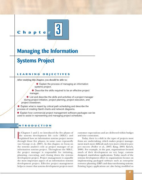
Chapter<br />
<strong>Managing</strong> <strong>the</strong> <strong>Information</strong><br />
<strong>Systems</strong> <strong>Project</strong><br />
LEARNING OBJECTIVES<br />
After studying this chapter, you should be able to:<br />
● Explain <strong>the</strong> process of managing an information<br />
systems project.<br />
● Describe <strong>the</strong> skills required to be an effective project<br />
manager.<br />
● List and describe <strong>the</strong> skills and activities of a project manager<br />
during project initiation, project planning, project execution, and<br />
project closedown.<br />
● Explain what is meant by critical path scheduling and describe <strong>the</strong><br />
process of creating Gantt charts and network diagrams.<br />
● Explain how commercial project management software packages can be<br />
used to assist in representing and managing project schedules.<br />
I NTRODUCTION<br />
3<br />
In Chapters 1 and 2, we introduced <strong>the</strong> five phases of<br />
<strong>the</strong> systems development life cycle (SDLC) and<br />
explained how an information systems project moves<br />
through those five phases, in some cases repeatedly<br />
(see George et al., 2007). In this chapter, we focus on<br />
<strong>the</strong> systems analyst’s role as project manager of an<br />
information systems project. Throughout <strong>the</strong> SDLC,<br />
<strong>the</strong> project manager is responsible for initiating,<br />
planning, executing, and closing down <strong>the</strong> systems<br />
development project. <strong>Project</strong> management is arguably<br />
<strong>the</strong> most important aspect of an information systems<br />
development project. Effective project management<br />
helps to ensure that systems development projects meet<br />
customer expectations and are delivered within budget<br />
and time constraints.<br />
Today, <strong>the</strong>re is a shift in <strong>the</strong> types of projects most<br />
firms are undertaking, which makes project management<br />
much more difficult and even more critical to project<br />
success (Fuller et al., 2007; King, 2003; Kirsch,<br />
2000). For example, in <strong>the</strong> past, organizations focused<br />
much of <strong>the</strong>ir development on very large, customdesigned,<br />
stand-alone applications. Today, much of <strong>the</strong><br />
systems development effort in organizations focuses on<br />
implementing packaged software such as enterprise<br />
resource planning (ERP) and data warehousing systems.<br />
Existing legacy applications are also being modified so<br />
47
48 CHAPTER 3 MANAGING THE INFORMATION SYSTEMS PROJECT<br />
that business-to-business transactions can occur seamlessly over <strong>the</strong> Internet. New<br />
Web-based interfaces are being added to existing legacy systems so that a broader<br />
range of users, often distributed globally, can access corporate information and systems.<br />
Additionally, software developed by global outsourcing partners that must be<br />
integrated into an organization’s existing portfolio of applications is now common<br />
practice (King, 2003). Working with vendors to supply applications, with customers or<br />
suppliers to integrate systems, or with a broader and more diverse user community<br />
requires that project managers be highly skilled. Consequently, it is important that<br />
you gain an understanding of <strong>the</strong> project management process; this will become a<br />
critical skill for your future success.<br />
In this chapter, we focus on <strong>the</strong> systems analyst’s role in managing information<br />
systems projects and will refer to this role as <strong>the</strong> project manager. The first section will<br />
provide <strong>the</strong> background for Pine Valley Furniture, a manufacturing company that we<br />
will visit throughout <strong>the</strong> remainder of <strong>the</strong> book. We will <strong>the</strong>n provide you with an<br />
understanding of <strong>the</strong> project manager’s role and <strong>the</strong> project management process.<br />
The discussion <strong>the</strong>n turns to techniques for reporting project plans using Gantt<br />
charts and network diagrams. The chapter will conclude with a discussion of <strong>the</strong> use<br />
of commercially available project management software that can be used to assist<br />
with a wide variety of project management activities.<br />
PINE VALLEY FURNITURE COMPANY<br />
BACKGROUND<br />
Pine Valley Furniture Company (PVF) manufactures high-quality wood furniture<br />
and distributes it to retail stores throughout <strong>the</strong> United States. Its product lines<br />
include dinette sets, stereo cabinets, wall units, living room furniture, and bedroom<br />
furniture. In <strong>the</strong> early 1980s, PVF’s founder, Alex Schuster, started to make and sell<br />
custom furniture in his garage. Alex managed invoices and kept track of customers by<br />
using file folders and a filing cabinet. By 1984, business expanded and Alex had to<br />
rent a warehouse and hire a part-time bookkeeper. PVF’s product line had multiplied,<br />
sales volume had doubled, and staff had increased to 50 employees. By 1990, PVF<br />
moved into its third and present location. Due to <strong>the</strong> added complexity of <strong>the</strong> company’s<br />
operations, Alex reorganized <strong>the</strong> company into <strong>the</strong> following functional areas:<br />
• Manufacturing, which was fur<strong>the</strong>r subdivided into three separate functions—<br />
Fabrication, Assembling, and Finishing<br />
• Sales<br />
• Orders<br />
• Accounting<br />
• Purchasing<br />
Alex and <strong>the</strong> heads of <strong>the</strong> functional areas established manual information systems,<br />
such as accounting ledgers and file folders, which worked well for a time.<br />
Eventually, however, PVF selected and installed a network server to automate invoicing,<br />
accounts receivable, and inventory control applications.<br />
When <strong>the</strong> applications were first computerized, each separate application had its<br />
own individual data files tailored to <strong>the</strong> needs of each functional area. As is typical in<br />
such situations, <strong>the</strong> applications closely resembled <strong>the</strong> manual systems on which <strong>the</strong>y<br />
were based. Three computer applications at Pine Valley Furniture are depicted in<br />
Figure 3-1: order filling, invoicing, and payroll. In <strong>the</strong> late 1990s, PVF formed a task<br />
force to study <strong>the</strong> possibility of moving to a database approach. After a preliminary<br />
study, management decided to convert its information systems to such an approach.<br />
The company upgraded its network server and implemented a centralized database
Program<br />
A<br />
Customer<br />
Master<br />
File<br />
Program<br />
B<br />
Order Filling<br />
System<br />
Program<br />
C<br />
Program<br />
A<br />
Invoicing<br />
System<br />
FOUNDATIONS FOR SYSTEMS DEVELOPMENT 49<br />
Orders Department Accounting Department<br />
Payroll Department<br />
Inventory<br />
Master<br />
File<br />
Back<br />
Order<br />
File<br />
Inventory<br />
Pricing<br />
File<br />
Program<br />
B<br />
Customer<br />
Master<br />
File<br />
management system. Today, PVF has successfully deployed an integrated, company-wide<br />
database and has converted its applications to work with <strong>the</strong> database. However, PVF is<br />
continuing to grow at a rapid rate, putting pressure on its current application systems.<br />
The computer-based applications at PVF support its business processes. When<br />
customers order furniture, <strong>the</strong>ir orders must be processed appropriately: Furniture<br />
must be built and shipped to <strong>the</strong> right customer and <strong>the</strong> right invoice mailed to <strong>the</strong><br />
right address. Employees have to be paid for <strong>the</strong>ir work. Given <strong>the</strong>se tasks, most of<br />
PVF’s computer-based applications are located in <strong>the</strong> accounting and financial areas.<br />
The applications include order filling, invoicing, accounts receivable, inventory control,<br />
accounts payable, payroll, and general ledger. At one time, each application had<br />
its own data files. For example, <strong>the</strong>re was a customer master file, an inventory master<br />
file, a back order file, an inventory pricing file, and an employee master file. The<br />
order filling system used data from three files: customer master, inventory master,<br />
and back order. Today, however, all systems are designed and integrated through a<br />
company-wide database in which data are organized around entities, or subjects,<br />
such as customers, invoices, and orders.<br />
PVF, like many firms, decided to develop its application software in-house; that<br />
is, it hired staff and bought <strong>the</strong> computer hardware and software necessary to build<br />
application software suited to its own needs. (O<strong>the</strong>r methods used to obtain application<br />
software were discussed in Chapter 2.) Although PVF continues to grow at a<br />
rapid rate, market conditions are becoming extremely competitive, especially with<br />
<strong>the</strong> advent of <strong>the</strong> Internet and <strong>the</strong> World Wide Web. Let’s see how a project manager<br />
plays a key role in developing a new information system for Pine Valley Furniture.<br />
MANAGING THE INFORMATION<br />
SYSTEMS PROJECT<br />
<strong>Project</strong> management is an important aspect of <strong>the</strong> development of information<br />
systems and a critical skill for a systems analyst. The focus of project management is<br />
to ensure that systems development projects meet customer expectations and are<br />
delivered within budget and time constraints.<br />
Program<br />
A<br />
Payroll<br />
System<br />
Employee<br />
Master<br />
File<br />
Program<br />
B<br />
Figure 3-1<br />
Three computer applications at<br />
Pine Valley Furniture: Order filling,<br />
invoicing, and payroll<br />
(Source: Hoffer, Prescott, and McFadden,<br />
2007.)
50 CHAPTER 3 MANAGING THE INFORMATION SYSTEMS PROJECT<br />
<strong>Project</strong> manager: A systems analyst<br />
with a diverse set of skills—<br />
management, leadership, technical,<br />
conflict management, and customer<br />
relationship—who is responsible for<br />
initiating, planning, executing, and<br />
closing down a project.<br />
<strong>Project</strong>: A planned undertaking of<br />
related activities to reach an<br />
objective that has a beginning and<br />
an end.<br />
Deliverable: An end product of an<br />
SDLC phase.<br />
Feasibility study: A study that<br />
determines if <strong>the</strong> proposed<br />
information system makes sense for<br />
<strong>the</strong> organization from an economic<br />
and operational standpoint.<br />
The project manager is a systems analyst with a diverse set of skills—management,<br />
leadership, technical, conflict management, and customer relationship—who<br />
is responsible for initiating, planning, executing, and closing down a project. As a<br />
project manager, your environment is one of continual change and problem solving.<br />
In some organizations, <strong>the</strong> project manager is a very experienced systems analyst,<br />
whereas in o<strong>the</strong>rs, both junior and senior analysts are expected to take on this role,<br />
managing parts of a project or actively supporting a more senior colleague who<br />
assumes <strong>the</strong> project manager role. Understanding <strong>the</strong> project management process<br />
is a critical skill for your future success.<br />
Creating and implementing successful projects requires managing <strong>the</strong><br />
resources, activities, and tasks needed to complete <strong>the</strong> information systems project.<br />
A project is a planned undertaking of a series of related activities to reach an<br />
objective that has a beginning and an end. The first question you might ask yourself<br />
is “Where do projects come from?” and, after considering all <strong>the</strong> different<br />
things that you could be asked to work on within an organization, “How do I know<br />
which projects to work on?” The ways in which each organization answers <strong>the</strong>se<br />
questions vary.<br />
In <strong>the</strong> rest of this section, we describe <strong>the</strong> process followed by Juanita Lopez and<br />
Chris Martin during <strong>the</strong> development of Pine Valley Furniture’s Purchasing<br />
Fulfillment System. Juanita works in <strong>the</strong> Order department, and Chris is a systems<br />
analyst.<br />
Juanita observed problems with <strong>the</strong> way orders were processed and reported:<br />
Sales growth had increased <strong>the</strong> workload for <strong>the</strong> Manufacturing department, and <strong>the</strong><br />
current systems no longer adequately supported <strong>the</strong> tracking of orders. It was becoming<br />
more difficult to track orders and get <strong>the</strong> right furniture and invoice to <strong>the</strong> right<br />
customers. Juanita contacted Chris, and toge<strong>the</strong>r <strong>the</strong>y developed a system that corrected<br />
<strong>the</strong>se Ordering department problems.<br />
The first deliverable, or end product, produced by Chris and Juanita was a<br />
System Service Request (SSR), a standard form PVF uses for requesting systems<br />
development work. Figure 3-2 shows an SSR for a purchasing fulfillment system. The<br />
form includes <strong>the</strong> name and contact information of <strong>the</strong> person requesting <strong>the</strong> system,<br />
a statement of <strong>the</strong> problem, and <strong>the</strong> name and contact information of <strong>the</strong> liaison<br />
and sponsor.<br />
This request was <strong>the</strong>n evaluated by <strong>the</strong> <strong>Systems</strong> Priority Board of PVF. Because<br />
all organizations have limited time and resources, not all requests can be approved.<br />
The board evaluates development requests in relation to <strong>the</strong> business problems or<br />
opportunities <strong>the</strong> system will solve or create; it also considers how <strong>the</strong> proposed<br />
project fits within <strong>the</strong> organization’s information systems architecture and longrange<br />
development plans. The review board selects those projects that best meet<br />
overall organizational objectives (we learn more about organizational objectives in<br />
Chapter 4). In <strong>the</strong> case of <strong>the</strong> Purchasing Fulfillment System request, <strong>the</strong> board<br />
found merit in <strong>the</strong> request and approved a more detailed feasibility study. A<br />
feasibility study, which is conducted by <strong>the</strong> project manager, involves determining<br />
if <strong>the</strong> information system makes sense for <strong>the</strong> organization from an economic and<br />
operational standpoint. The study takes place before <strong>the</strong> system is constructed.<br />
Figure 3-3 is a graphical view of <strong>the</strong> steps followed during <strong>the</strong> project initiation of<br />
<strong>the</strong> Purchasing Fulfillment System.<br />
In summary, systems development projects are undertaken for two primary reasons:<br />
to take advantage of business opportunities and to solve business problems.<br />
Taking advantage of an opportunity might mean providing an innovative service to<br />
customers through <strong>the</strong> creation of a new system. For example, PVF may want to create<br />
a Web site so that customers can easily access its catalog and place orders at any<br />
time. Solving a business problem could involve modifying <strong>the</strong> way an existing system<br />
processes data so that more accurate or timely information is provided to
Pine Valley Furniture<br />
System Service Request<br />
REQUESTED BY<br />
DEPARTMENT<br />
LOCATION<br />
CONTACT<br />
TYPE OF REQUEST<br />
[<br />
[<br />
[<br />
X<br />
]<br />
]<br />
]<br />
New System<br />
PROBLEM STATEMENT<br />
Juanita Lopez<br />
Purchasing, Manufacturing Support<br />
Headquarters, 1-322<br />
Tel: 4-3267 FAX: 4-3270 e-mail: jlopez<br />
System Enhancement<br />
System Error Correction<br />
URGENCY<br />
[ ]<br />
[<br />
[<br />
X<br />
]<br />
]<br />
DATE<br />
FOUNDATIONS FOR SYSTEMS DEVELOPMENT 51<br />
October 1, 2007<br />
Immediate – Operations are impaired or<br />
opportunity lost<br />
Problems exist, but can be worked around<br />
Business losses can be tolerated until new<br />
system installed<br />
Sales growth at PVF has caused greater volume of work for <strong>the</strong> manufacturing support unit within Purchasing. Fur<strong>the</strong>r,<br />
more concentration on customer service has reduced manufacturing lead times, which puts more pressure on purchasing<br />
activities. In addition, cost-cutting measures force Purchasing to be more aggressive in negotiating terms with vendors,<br />
improving delivery times, and lowering our investments in inventory. The current modest systems support for<br />
Manufacturing/Purchasing is not responsive to <strong>the</strong>se new business conditions. Data are not available, information cannot<br />
be summarized, supplier orders cannot be adequately tracked, and commodity buying is not well supported. PVF is<br />
spending too much on raw materials and not being responsive to manufacturing needs.<br />
SERVICE REQUEST<br />
I request a thorough analysis of our current operations with <strong>the</strong> intent to design and build a completely new information<br />
system. This system should handle all purchasing transactions, support display and reporting of critical purchasing data,<br />
and assist purchasing agents in commodity buying.<br />
IS LIAISON<br />
SPONSOR<br />
[<br />
[<br />
[<br />
[<br />
Chris Martin (Tel: 4-6204 FAX: 4-6200 e-mail: cmartin)<br />
Sal Divario, Director, Purchasing<br />
]<br />
]<br />
]<br />
]<br />
TO BE COMPLETED BY SYSTEMS PRIORITY BOARD<br />
Request approved Assigned to<br />
Start date<br />
Recommend revision<br />
Suggest user development<br />
Reject for reason<br />
users. For example, a company such as PVF may create a password-protected<br />
intranet site that contains important announcements and budget information. Of<br />
course, projects are not always initiated for <strong>the</strong> aforementioned rational reasons<br />
(taking advantage of business opportunities or solving business problems). For<br />
example, in some instances, organizations and government undertake projects to<br />
spend resources, to attain or pad budgets, to keep people busy, or to help train<br />
people and develop <strong>the</strong>ir skills. Our focus in this chapter is not on how and why<br />
organizations identify projects but on <strong>the</strong> management of projects once <strong>the</strong>y have<br />
been identified.<br />
Once a potential project has been identified, an organization must determine<br />
<strong>the</strong> resources required for its completion. This is done by analyzing <strong>the</strong> scope of<br />
<strong>the</strong> project and determining <strong>the</strong> probability of successful completion. After getting<br />
this information, <strong>the</strong> organization can <strong>the</strong>n determine whe<strong>the</strong>r taking advantage<br />
of an opportunity or solving a particular problem is feasible within time and<br />
resource constraints. If deemed feasible, a more detailed project analysis is <strong>the</strong>n<br />
conducted. As you will see, <strong>the</strong> ability to determine <strong>the</strong> size, scope, and resource<br />
requirements of a project is just one of <strong>the</strong> many skills that a project manager<br />
Figure 3-2<br />
System Service Request for<br />
Purchasing Fulfillment System with<br />
name and contact information of<br />
<strong>the</strong> person requesting <strong>the</strong> system,<br />
a statement of <strong>the</strong> problem, and<br />
<strong>the</strong> name and contact information<br />
of <strong>the</strong> liaison and sponsor.
52 CHAPTER 3 MANAGING THE INFORMATION SYSTEMS PROJECT<br />
Figure 3-3<br />
A graphical view of <strong>the</strong> five steps<br />
followed during <strong>the</strong> project<br />
initiation of <strong>the</strong> Purchasing<br />
Fulfillment System<br />
<strong>Project</strong> management: A controlled<br />
process of initiating, planning,<br />
executing, and closing down a<br />
project.<br />
<strong>Project</strong> initiation: The first phase<br />
of <strong>the</strong> project management process<br />
in which activities are performed to<br />
assess <strong>the</strong> size, scope, and<br />
complexity of <strong>the</strong> project and to<br />
establish procedures to support later<br />
project activities.<br />
1.<br />
2.<br />
3.<br />
4.<br />
5.<br />
Juanita observed problems with existing<br />
purchasing system.<br />
Juanita contacted Chris within <strong>the</strong> IS development<br />
group to initiate a System Service Request.<br />
SSR was reviewed and approved by <strong>Systems</strong><br />
Priority Board.<br />
Steering committee was assigned to oversee project.<br />
Detailed project plan was developed and executed.<br />
must possess. A project manager is often thought of as a juggler keeping aloft<br />
many balls, which reflect <strong>the</strong> various aspects of a project’s development, as<br />
depicted in Figure 3-4.<br />
To successfully orchestrate <strong>the</strong> construction of a complex information system,<br />
a project manager must have interpersonal, leadership, and technical skills.<br />
Table 3-1 lists <strong>the</strong> project manager’s common skills and activities. Note that many<br />
of <strong>the</strong> skills are related to personnel or general management, not simply technical<br />
skills. Table 3-1 shows that not only does an effective project manager have<br />
varied skills, but he or she is also <strong>the</strong> most instrumental person to <strong>the</strong> successful<br />
completion of any project.<br />
The remainder of this chapter will focus on <strong>the</strong> project management process,<br />
which involves four phases:<br />
1. Initiating <strong>the</strong> project<br />
2. Planning <strong>the</strong> project<br />
3. Executing <strong>the</strong> project<br />
4. Closing down <strong>the</strong> project<br />
Several activities must be performed during each of <strong>the</strong>se four phases. Following<br />
this formal project management process greatly increases <strong>the</strong> likelihood of project<br />
success.<br />
Initiating a <strong>Project</strong><br />
During project initiation, <strong>the</strong> project manager performs several activities to<br />
assess <strong>the</strong> size, scope, and complexity of <strong>the</strong> project and to establish procedures to<br />
support subsequent activities. Depending on <strong>the</strong> project, some initiation activities
<strong>Systems</strong><br />
Development<br />
Life Cycle<br />
Technological<br />
Change<br />
Organizational<br />
Change and<br />
Complexity<br />
Contractors<br />
and Vendors<br />
Customer and<br />
Management<br />
Expectations<br />
The Art<br />
of<br />
<strong>Project</strong><br />
Management<br />
<strong>Managing</strong><br />
People<br />
TABLE 3-1 Common Activities and Skills of a <strong>Project</strong> Manager<br />
Documentation<br />
and<br />
Communication<br />
Time and<br />
Resource<br />
Constraints<br />
Methodologies<br />
and Tools<br />
Activity Description Skill<br />
FOUNDATIONS FOR SYSTEMS DEVELOPMENT 53<br />
Figure 3-4<br />
A project manager juggles<br />
numerous activities<br />
Leadership Influencing <strong>the</strong> activities of o<strong>the</strong>rs toward <strong>the</strong> Communication; liaison between management,<br />
attainment of a common goal through <strong>the</strong> users, and developers; assigning activities;<br />
use of intelligence, personality, and abilities monitoring progress<br />
Management Getting projects completed through <strong>the</strong> Defining and sequencing activities; communicating<br />
effective utilization of resources expectations; assigning resources to activities;<br />
monitoring outcomes<br />
Customer relations Working closely with customers to assure Interpreting system requests and specifications; site<br />
project deliverables meet expectations preparation and user training; contact point for customers<br />
Technical problem Designing and sequencing activities to attain Interpreting system requests and specifications; defining<br />
solving project goals activities and <strong>the</strong>ir sequence; making trade-offs<br />
between alternative solutions; designing solutions to<br />
problems<br />
Conflict management <strong>Managing</strong> conflict within a project team to Problem solving; smoothing out personality differences;<br />
assure that conflict is not too high or too low compromising; goal setting<br />
Team management <strong>Managing</strong> <strong>the</strong> project team for effective Communication within and between teams; peer evaluations;<br />
team performance conflict resolution; team building; self-management<br />
Risk and change Identifying, assessing, and managing <strong>the</strong> Environmental scanning; risk and opportunity<br />
management risks and day-to-day changes that occur identification and assessment; forecasting;<br />
during a project resource redeployment
54 CHAPTER 3 MANAGING THE INFORMATION SYSTEMS PROJECT<br />
Figure 3-5<br />
Six project initiation activities<br />
<strong>Project</strong> Initiation<br />
1. Establishing <strong>the</strong> <strong>Project</strong> Initiation Team<br />
2. Establishing a Relationship with <strong>the</strong> Customer<br />
3. Establishing <strong>the</strong> <strong>Project</strong> Initiation Plan<br />
4. Establishing Management Procedures<br />
5. Establishing <strong>the</strong> <strong>Project</strong> Management<br />
Environment and <strong>Project</strong> Workbook<br />
6. Developing <strong>the</strong> <strong>Project</strong> Charter<br />
may be unnecessary and some may be very involved. The types of activities you will<br />
perform when initiating a project are summarized in Figure 3-5 and described next.<br />
1. Establishing <strong>the</strong> project initiation team. This activity involves organizing an initial<br />
core of project team members to assist in accomplishing <strong>the</strong> project initiation<br />
activities (Verma, 1996, 1997). For example, during <strong>the</strong> Purchasing<br />
Fulfillment System project at PVF, Chris Martin was assigned to support <strong>the</strong><br />
Purchasing department. It is a PVF policy that all initiation teams consist of at<br />
least one user representative, in this case Juanita Lopez, and one member of<br />
<strong>the</strong> IS development group. Therefore, <strong>the</strong> project initiation team consisted of<br />
Chris and Juanita; Chris was <strong>the</strong> project manager.<br />
2. Establishing a relationship with <strong>the</strong> customer. A thorough understanding of your<br />
customer builds stronger partnerships and higher levels of trust. At PVF, management<br />
has tried to foster strong working relationships between business<br />
units (like Purchasing) and <strong>the</strong> IS development group by assigning a specific<br />
individual to work as a liaison between both groups. Because Chris had been<br />
assigned to <strong>the</strong> Purchasing unit for some time, he was already aware of some<br />
of <strong>the</strong> problems with <strong>the</strong> existing purchasing systems. PVF’s policy of assigning<br />
specific individuals to each business unit helped to ensure that both Chris and<br />
Juanita were comfortable working toge<strong>the</strong>r prior to <strong>the</strong> initiation of <strong>the</strong> project.<br />
Many organizations use a similar mechanism for establishing relationships<br />
with customers.<br />
3. Establishing <strong>the</strong> project initiation plan. This step defines <strong>the</strong> activities required to<br />
organize <strong>the</strong> initiation team while it is working to define <strong>the</strong> goals and scope<br />
of <strong>the</strong> project (Abdel-Hamid et al., 1999). Chris’s role was to help Juanita<br />
translate her business requirements into a written request for an improved<br />
information system. This required <strong>the</strong> collection, analysis, organization, and<br />
transformation of a lot of information. Because Chris and Juanita were<br />
already familiar with each o<strong>the</strong>r and <strong>the</strong>ir roles within a development project,<br />
<strong>the</strong>y next needed to define when and how <strong>the</strong>y would communicate, define<br />
deliverables and project steps, and set deadlines. Their initiation plan<br />
included agendas for several meetings. These steps eventually led to <strong>the</strong> creation<br />
of <strong>the</strong>ir SSR form.<br />
4. Establishing management procedures. Successful projects require <strong>the</strong> development<br />
of effective management procedures. Within PVF, many of <strong>the</strong>se management<br />
procedures had been established as standard operating procedures<br />
by <strong>the</strong> <strong>Systems</strong> Priority Board and <strong>the</strong> IS development group. For example, all<br />
project development work is charged back to <strong>the</strong> functional unit requesting<br />
<strong>the</strong> work. In o<strong>the</strong>r organizations, each project may have unique procedures
tailored to its needs. Yet, in general, when establishing procedures, you are<br />
concerned with developing team communication and reporting procedures,<br />
job assignments and roles, project change procedures, and determining how<br />
project funding and billing will be handled. It was fortunate for Chris and<br />
Juanita that most of <strong>the</strong>se procedures were already established at PVF, allowing<br />
<strong>the</strong>m to move on to o<strong>the</strong>r project activities.<br />
5. Establishing <strong>the</strong> project management environment and project workbook. The focus of<br />
this activity is to collect and organize <strong>the</strong> tools that you will use while managing<br />
<strong>the</strong> project and to construct <strong>the</strong> project workbook. Diagrams, charts, and<br />
system descriptions provide much of <strong>the</strong> project workbook contents. Thus,<br />
<strong>the</strong> project workbook serves as a repository for all project correspondence,<br />
inputs, outputs, deliverables, procedures, and standards established by <strong>the</strong><br />
project team (Rettig, 1990). The project workbook can be stored as an online<br />
electronic document or in a large three-ring binder. The project workbook is<br />
used by all team members and is useful for project audits, orientation of new<br />
team members, communication with management and customers, identifying<br />
future projects, and performing post-project reviews. The establishment and<br />
diligent recording of all project information in <strong>the</strong> workbook are two of <strong>the</strong><br />
most important activities you will perform as project manager.<br />
Figure 3-6 shows <strong>the</strong> project workbook for <strong>the</strong> Purchasing Fulfillment<br />
System. It consists of both a large hard-copy binder and electronic information<br />
where <strong>the</strong> system data dictionary, a catalog of data stored in <strong>the</strong> database,<br />
and diagrams are stored. For this system, all project documents can fit into a<br />
single binder. It is not unusual, though, for project documentation to be<br />
spread over several binders. As more information is captured and recorded<br />
electronically, however, fewer hard-copy binders may be needed. Many project<br />
teams keep <strong>the</strong>ir project workbooks on <strong>the</strong> Web. A Web site can be created so<br />
that all project members can easily access all project documents. This Web site<br />
can be a simple repository of documents or an elaborate site with password<br />
Pine Valley Furniture<br />
<strong>Information</strong> <strong>Systems</strong><br />
Development Group<br />
Purchasing Fulfillment System<br />
Manager: Chris Martin<br />
1<br />
2<br />
3<br />
4<br />
5<br />
6<br />
7<br />
8<br />
9<br />
1.<br />
2.<br />
3.<br />
4.<br />
5.<br />
6.<br />
7.<br />
8.<br />
9.<br />
<strong>Project</strong> overview<br />
Initiation plan and SSR<br />
<strong>Project</strong> scope and risks<br />
Management procedures<br />
Data descriptions<br />
Process descriptions<br />
Team correspondence<br />
<strong>Project</strong> Charter<br />
<strong>Project</strong> schedule<br />
Online copies of data dictionary,<br />
diagrams, schedules, reports, etc.<br />
FOUNDATIONS FOR SYSTEMS DEVELOPMENT 55<br />
<strong>Project</strong> workbook: An online or<br />
hard-copy repository for all project<br />
correspondence, inputs, outputs,<br />
deliverables, procedures, and<br />
standards that is used for<br />
performing project audits, orienting<br />
new team members, communicating<br />
with management and customers,<br />
identifying future projects, and<br />
performing post-project reviews.<br />
Figure 3-6<br />
The project workbook for <strong>the</strong><br />
Purchase Fulfillment System<br />
project contains nine key<br />
documents in both hard-copy and<br />
electronic form
56 CHAPTER 3 MANAGING THE INFORMATION SYSTEMS PROJECT<br />
<strong>Project</strong> charter: A short, high-level<br />
document prepared for both<br />
internal and external stakeholders<br />
to formally announce <strong>the</strong><br />
establishment of <strong>the</strong> project and to<br />
briefly describe its objectives, key<br />
assumptions, and stakeholders.<br />
<strong>Project</strong> planning: The second<br />
phase of <strong>the</strong> project management<br />
process that focuses on defining<br />
clear, discrete activities and <strong>the</strong> work<br />
needed to complete each activity<br />
within a single project.<br />
Figure 3-7<br />
Level of project planning detail<br />
should be high in <strong>the</strong> short term,<br />
with less detail as time goes on<br />
protection and security levels. The best feature of using <strong>the</strong> Web as your<br />
repository is that it enables project members and customers to review a project’s<br />
status and all related information continually.<br />
6. Developing <strong>the</strong> project charter. The project charter is a short, (typically one page)<br />
high-level document prepared for both internal and external stakeholders to<br />
formally announce <strong>the</strong> establishment of <strong>the</strong> project and to briefly describe its<br />
objectives, key assumptions, and stakeholders. The project charter ensures<br />
that both you and your customer gain a common understanding of <strong>the</strong> project.<br />
It is also a very useful communication tool; it helps to announce to <strong>the</strong><br />
organization that a particular project has been chosen for development.<br />
<strong>Project</strong> initiation is complete once <strong>the</strong>se six activities have been performed.<br />
Before moving on to <strong>the</strong> next phase of <strong>the</strong> project, <strong>the</strong> work performed during project<br />
initiation is reviewed at a meeting attended by management, customers, and project<br />
team members. An outcome of this meeting is a decision to continue, modify, or<br />
abandon <strong>the</strong> project. In <strong>the</strong> case of <strong>the</strong> Purchasing Fulfillment System project at Pine<br />
Valley Furniture, <strong>the</strong> board accepted <strong>the</strong> SSR and selected a project steering committee<br />
to monitor project progress and to provide guidance to <strong>the</strong> team members<br />
during subsequent activities. If <strong>the</strong> scope of <strong>the</strong> project is modified, it may be necessary<br />
to return to project initiation activities and collect additional information. Once<br />
a decision is made to continue <strong>the</strong> project, a much more detailed project plan is<br />
developed during <strong>the</strong> project planning phase.<br />
Planning <strong>the</strong> <strong>Project</strong><br />
The next step in <strong>the</strong> project management process is project planning. Research<br />
has found a positive relationship between effective project planning and positive project<br />
outcomes (Guinan et al., 1998; Kirsch, 2000). <strong>Project</strong> planning involves defining<br />
clear, discrete activities and <strong>the</strong> work needed to complete each activity within a single<br />
project. It often requires you to make numerous assumptions about <strong>the</strong> availability of<br />
resources such as hardware, software, and personnel. It is much easier to plan nearerterm<br />
activities than those occurring in <strong>the</strong> future. In actual fact, you often have to<br />
construct longer-term plans that are more general in scope and nearer-term plans<br />
that are more detailed. The repetitive nature of <strong>the</strong> project management process<br />
requires that plans be constantly monitored throughout <strong>the</strong> project and periodically<br />
updated (usually after each phase) based upon <strong>the</strong> most recent information.<br />
Figure 3-7 illustrates <strong>the</strong> principle that nearer-term plans are typically more specific<br />
and firmer than longer-term plans. For example, it is virtually impossible to rigorously<br />
plan activities late in <strong>the</strong> project without first completing <strong>the</strong> earlier activities.<br />
Planning Detail<br />
High<br />
Medium<br />
Low<br />
1 Week<br />
Out<br />
1 Month<br />
Out<br />
Planning Horizon<br />
6 Months<br />
Out
<strong>Project</strong> Planning<br />
1. Describing <strong>Project</strong> Scope, Alternatives,<br />
and Feasibility<br />
2. Dividing <strong>the</strong> <strong>Project</strong> into Manageable Tasks<br />
3. Estimating Resources and Creating a<br />
Resource Plan<br />
4. Developing a Preliminary Schedule<br />
5. Developing a Communication Plan<br />
6. Determining <strong>Project</strong> Standards and Procedures<br />
7. Identifying and Assessing Risk<br />
8. Creating a Preliminary Budget<br />
9. Developing a <strong>Project</strong> Scope Statement<br />
10. Setting a Baseline <strong>Project</strong> Plan<br />
Also, <strong>the</strong> outcome of activities performed earlier in <strong>the</strong> project is likely to impact<br />
later activities. This means that it is very difficult, and very likely inefficient, to try to<br />
plan detailed solutions for activities that will occur far into <strong>the</strong> future.<br />
As with <strong>the</strong> project initiation process, varied and numerous activities must be<br />
performed during project planning. For example, during <strong>the</strong> Purchasing Fulfillment<br />
System project, Chris and Juanita developed a 10-page plan. However, project plans<br />
for very large systems may be several hundred pages in length. The types of activities<br />
that you can perform during project planning are summarized in Figure 3-8 and are<br />
described in <strong>the</strong> following list:<br />
1. Describing project scope, alternatives, and feasibility. The purpose of this activity is<br />
to understand <strong>the</strong> content and complexity of <strong>the</strong> project. Within PVF’s systems<br />
development methodology, one of <strong>the</strong> first meetings must focus on<br />
defining a project’s scope. Although project scope information was not<br />
included in <strong>the</strong> SSR developed by Chris and Juanita, it was important that<br />
both shared <strong>the</strong> same vision for <strong>the</strong> project before moving too far along.<br />
During this activity, you should reach agreement on <strong>the</strong> following questions:<br />
• What problem or opportunity does <strong>the</strong> project address?<br />
• What are <strong>the</strong> quantifiable results to be achieved?<br />
• What needs to be done?<br />
• How will success be measured?<br />
• How will we know when we are finished?<br />
After defining <strong>the</strong> scope of <strong>the</strong> project, your next objective is to identify and<br />
document general alternative solutions for <strong>the</strong> current business problem or<br />
opportunity. You must <strong>the</strong>n assess <strong>the</strong> feasibility of each alternative solution and<br />
choose which to consider during subsequent SDLC phases. In some instances,<br />
off-<strong>the</strong>-shelf software can be found. It is also important that any unique problems,<br />
constraints, and assumptions about <strong>the</strong> project be clearly stated.<br />
2. Dividing <strong>the</strong> project into manageable tasks. This is a critical activity during <strong>the</strong> project<br />
planning process. Here, you must divide <strong>the</strong> entire project into manageable<br />
tasks and <strong>the</strong>n logically order <strong>the</strong>m to ensure a smooth evolution between tasks.<br />
FOUNDATIONS FOR SYSTEMS DEVELOPMENT 57<br />
Figure 3-8<br />
Ten project management activities
58 CHAPTER 3 MANAGING THE INFORMATION SYSTEMS PROJECT<br />
Figure 3-9<br />
Gantt chart showing project tasks,<br />
duration times for those tasks, and<br />
predecessors<br />
Work breakdown structure: The<br />
process of dividing <strong>the</strong> project into<br />
manageable tasks and logically<br />
ordering <strong>the</strong>m to ensure a smooth<br />
evolution between tasks.<br />
Gantt chart: A graphical<br />
representation of a project that<br />
shows each task as a horizontal bar<br />
whose length is proportional to its<br />
time for completion.<br />
The definition of tasks and <strong>the</strong>ir sequence is referred to as <strong>the</strong> work breakdown<br />
structure (PMBOK, 2004; <strong>Project</strong> Management Institute, 2002). Some tasks may<br />
be performed in parallel whereas o<strong>the</strong>rs must follow one ano<strong>the</strong>r sequentially.<br />
Task sequence depends on which tasks produce deliverables needed in o<strong>the</strong>r<br />
tasks, when critical resources are available, <strong>the</strong> constraints placed on <strong>the</strong> project<br />
by <strong>the</strong> client, and <strong>the</strong> process outlined in <strong>the</strong> SDLC.<br />
For example, suppose that you are working on a new development project<br />
and need to collect system requirements by interviewing users of <strong>the</strong> new system<br />
and reviewing reports <strong>the</strong>y currently use to do <strong>the</strong>ir job. A work breakdown<br />
for <strong>the</strong>se activities is represented in a Gantt chart in Figure 3-9. A Gantt<br />
chart is a graphical representation of a project that shows each task as a horizontal<br />
bar whose length is proportional to its time for completion. Different<br />
colors, shades, or shapes can be used to highlight each kind of task. For example,<br />
those activities on <strong>the</strong> critical path (defined later) may be in red and a<br />
summary task could have a special bar. Note that <strong>the</strong> black horizontal bars—<br />
rows 1, 2, and 6 in Figure 3-9—represent summary tasks. Planned versus<br />
actual times or progress for an activity can be compared by parallel bars of different<br />
colors, shades, or shapes. Gantt charts do not (typically) show how tasks<br />
must be ordered (precedence), but simply show when an activity should begin<br />
and end. In Figure 3-9, <strong>the</strong> task duration is shown in <strong>the</strong> second column by<br />
days, “d,” and necessary prior tasks are noted in <strong>the</strong> third column as predecessors.<br />
Most project management software tools support a broad range of<br />
task durations, including minutes, hours, days, weeks, and months. As you will<br />
learn in later chapters, <strong>the</strong> SDLC consists of several phases that you will need<br />
to break down into activities. Creating a work breakdown structure requires<br />
that you decompose phases into activities—summary tasks—and activities into<br />
specific tasks. For example, Figure 3-9 shows that <strong>the</strong> activity Interviewing consists<br />
of three tasks: design interview form, schedule appointments, and conduct<br />
interviews.<br />
Defining tasks in too much detail will make <strong>the</strong> management of <strong>the</strong> project<br />
unnecessarily complex. You will develop <strong>the</strong> skill of discovering <strong>the</strong> optimal<br />
level of detail for representing tasks through experience. For example, it<br />
may be very difficult to list tasks that require less than one hour of time to<br />
complete in a final work breakdown structure. Alternatively, choosing tasks
that are too large in scope (e.g., several weeks long) will not provide you with<br />
a clear sense of <strong>the</strong> status of <strong>the</strong> project or of <strong>the</strong> interdependencies between<br />
tasks. What are <strong>the</strong> characteristics of a “task”? A task<br />
• Can be done by one person or a well-defined group<br />
• Has a single and identifiable deliverable (The task is, however, <strong>the</strong> process<br />
of creating <strong>the</strong> deliverable.)<br />
• Has a known method or technique<br />
• Has well-accepted predecessor and successor steps<br />
• Is measurable so that percent completed can be determined<br />
3. Estimating resources and creating a resource plan. The goal of this activity is to estimate<br />
resource requirements for each project activity and to use this information<br />
to create a project resource plan. The resource plan helps assemble and<br />
deploy resources in <strong>the</strong> most effective manner. For example, you would not<br />
want to bring additional programmers onto <strong>the</strong> project at a rate faster than<br />
you could prepare work for <strong>the</strong>m. <strong>Project</strong> managers use a variety of tools to<br />
assist in making estimates of project size and costs. The most widely used<br />
method is called COCOMO (COnstructive COst MOdel), which uses parameters<br />
that were derived from prior projects of differing complexity (Boehm et<br />
al., 2000). COCOMO uses <strong>the</strong>se different parameters to predict human<br />
resource requirements for basic, intermediate, and very complex systems (see<br />
Figure 3-10).<br />
People are <strong>the</strong> most important, and expensive, part of project resource<br />
planning. <strong>Project</strong> time estimates for task completion and overall system quality<br />
are significantly influenced by <strong>the</strong> assignment of people to tasks. It is<br />
important to give people tasks that allow <strong>the</strong>m to learn new skills. It is equally<br />
important to make sure that project members are not “in over <strong>the</strong>ir heads” or<br />
FOUNDATIONS FOR SYSTEMS DEVELOPMENT 59<br />
Figure 3-10<br />
COCOMO is used by many project<br />
managers to estimate project<br />
resources<br />
(Source: USC-COCOMO II.2000.00 from<br />
Software Cost Estimation with COCOMO II,<br />
USC Center for Software Engineering.<br />
Courtesy of USC.)
60 CHAPTER 3 MANAGING THE INFORMATION SYSTEMS PROJECT<br />
Figure 3-11<br />
Trade-offs between <strong>the</strong> quality of<br />
<strong>the</strong> program code versus <strong>the</strong><br />
speed of programming<br />
Network diagram: A diagram that<br />
depicts project tasks and <strong>the</strong>ir<br />
interrelationships.<br />
Quality of Work<br />
High<br />
Low<br />
Adam<br />
Brenda<br />
Carl<br />
Short<br />
Long<br />
Time of Programming a Task<br />
working on a task that is not well suited to <strong>the</strong>ir skills. Resource estimates may<br />
need to be revised based upon <strong>the</strong> skills of <strong>the</strong> actual person (or people)<br />
assigned to a particular activity. Figure 3-11 indicates <strong>the</strong> relative programming<br />
speed versus <strong>the</strong> relative programming quality of three programmers.<br />
The figure suggests that Carl should not be assigned tasks in which completion<br />
time is critical and that Brenda should be assigned tasks in which high<br />
quality is most vital.<br />
One approach to assigning tasks is to assign a single task type (or only a<br />
few task types) to each worker for <strong>the</strong> duration of <strong>the</strong> project. For example,<br />
you could assign one worker to create all computer displays and ano<strong>the</strong>r to<br />
create all system reports. Such specialization ensures that both workers<br />
become efficient at <strong>the</strong>ir own particular tasks. A worker may become bored if<br />
<strong>the</strong> task is too specialized or is long in duration, so you could assign workers to<br />
a wider variety of tasks. However, this approach may lead to lowered task efficiency.<br />
A middle ground would be to make assignments with a balance of both<br />
specialization and task variety. Assignments depend on <strong>the</strong> size of <strong>the</strong> development<br />
project and <strong>the</strong> skills of <strong>the</strong> project team. Regardless of <strong>the</strong> manner in<br />
which you assign tasks, make sure that each team member works only on one<br />
task at a time. Exceptions to this rule can occur when a task occupies only a<br />
small portion of a team member’s time (e.g., testing <strong>the</strong> programs developed<br />
by ano<strong>the</strong>r team member) or during an emergency.<br />
4. Developing a preliminary schedule. During this activity, you use <strong>the</strong> information<br />
on tasks and resource availability to assign time estimates to each activity in<br />
<strong>the</strong> work breakdown structure. These time estimates will enable you to create<br />
target starting and ending dates for <strong>the</strong> project. Target dates can be revisited<br />
and modified until a schedule is produced that is acceptable to <strong>the</strong> customer.<br />
Determining an acceptable schedule may require that you find additional or<br />
different resources or that <strong>the</strong> scope of <strong>the</strong> project be changed. The schedule<br />
may be represented as a Gantt chart, as illustrated in Figure 3-9, or as a network<br />
diagram, as illustrated in Figure 3-12. A network diagram is a graphical<br />
depiction of project tasks and <strong>the</strong>ir interrelationships. As with a Gantt chart,<br />
each type of task can be highlighted by different features on <strong>the</strong> network diagram.<br />
The distinguishing feature of a network diagram is that <strong>the</strong> ordering of<br />
tasks is shown by connecting tasks—depicted as rectangles or ovals—with<br />
<strong>the</strong>ir predecessor and successor tasks. However, <strong>the</strong> relative size of a node<br />
(representing a task) or a gap between nodes does not imply <strong>the</strong> task’s duration.<br />
Only <strong>the</strong> individual task items are drawn on a network diagram, which is<br />
why <strong>the</strong> summary tasks 1, 2, and 6—<strong>the</strong> black bars—from Figure 3-9 are not<br />
shown in Figure 3-12. We describe both of <strong>the</strong>se charts later in this chapter.
5. Developing a communication plan. The goal of this activity is to outline <strong>the</strong> communication<br />
procedures among management, project team members, and <strong>the</strong><br />
customer. The communication plan includes when and how written and oral<br />
reports will be provided by <strong>the</strong> team, how team members will coordinate<br />
work, what messages will be sent to announce <strong>the</strong> project to interested parties,<br />
and what kinds of information will be shared with vendors and external contractors<br />
involved with <strong>the</strong> project. It is important that free and open communication<br />
occur among all parties with respect to proprietary information and<br />
confidentiality with <strong>the</strong> customer (Fuller et al., 2007; Kettelhut, 1991; Kirsch,<br />
2000; Verma, 1996). When developing a communication plan, numerous<br />
questions must be answered in order to assure that <strong>the</strong> plan is comprehensive<br />
and complete, including:<br />
• Who are <strong>the</strong> stakeholders for this project?<br />
• What information does each stakeholder need?<br />
• When, and at what interval, does this information need to be produced?<br />
• What sources will be used to ga<strong>the</strong>r and generate this information?<br />
• Who will collect, store, and verify <strong>the</strong> accuracy of this information?<br />
• Who will organize and package this information into a document?<br />
• Who will be <strong>the</strong> contact person for each stakeholder should any questions<br />
arise?<br />
• What format will be used to package this information?<br />
• What communication medium will be most effective for delivering this<br />
information to <strong>the</strong> stakeholder?<br />
Once <strong>the</strong>se questions are answered for each stakeholder, a comprehensive<br />
communication plan can be developed. In this plan, a summary of communication<br />
documents, work assignments, schedules, and distribution methods will be<br />
outlined. Additionally, a project communication matrix can be developed<br />
which provides a summary of <strong>the</strong> overall communication plan (see Figure 3-13).<br />
This matrix can be easily shared among team members, and verified by stakeholders<br />
outside <strong>the</strong> project team, so that <strong>the</strong> right people are getting <strong>the</strong> right<br />
information at <strong>the</strong> right time, and in <strong>the</strong> right format.<br />
FOUNDATIONS FOR SYSTEMS DEVELOPMENT 61<br />
Figure 3-12<br />
A network diagram illustrates tasks<br />
with rectangles (or ovals) and <strong>the</strong><br />
relationships and sequences of<br />
those activities with arrows
62 CHAPTER 3 MANAGING THE INFORMATION SYSTEMS PROJECT<br />
Stakeholder<br />
Team Members<br />
Management Supervisor<br />
User Group<br />
Internal IT Staff<br />
It Manager<br />
Contract Programmers<br />
Training Subcontractor<br />
Figure 3-13<br />
The <strong>Project</strong> Communication Matrix<br />
provides a high-level summary of<br />
<strong>the</strong> communication plan<br />
Document<br />
<strong>Project</strong> Status Report<br />
<strong>Project</strong> Status Report<br />
<strong>Project</strong> Status Report<br />
<strong>Project</strong> Status Report<br />
<strong>Project</strong> Status Report<br />
Software Specifications<br />
Implementation and<br />
Training Plan<br />
Format<br />
<strong>Project</strong> Intranet<br />
Hard Copy<br />
Hard Copy<br />
Email<br />
Hard Copy<br />
E-mail/<strong>Project</strong> Intranet<br />
Hard Copy<br />
Team Contact<br />
Juan<br />
Kim<br />
Juan<br />
Kim<br />
James<br />
Kim<br />
Jackie<br />
James<br />
Juan<br />
Jeremy<br />
Jordan<br />
Kim<br />
Jordan<br />
James<br />
Date Due<br />
First Monday of Month<br />
First Monday of Month<br />
First Monday of Month<br />
First Monday of Month<br />
First Monday of Month<br />
October 1, 2007<br />
January 7, 2008<br />
6. Determining project standards and procedures. During this activity, you will specify<br />
how various deliverables are produced and tested by you and your project<br />
team. For example, <strong>the</strong> team must decide on which tools to use, how <strong>the</strong><br />
standard SDLC might be modified, which SDLC methods will be used, documentation<br />
styles (e.g., type fonts and margins for user manuals), how team<br />
members will report <strong>the</strong> status of <strong>the</strong>ir assigned activities, and terminology.<br />
Setting project standards and procedures for work acceptance is a way to<br />
ensure <strong>the</strong> development of a high-quality system. Also, it is much easier to<br />
train new team members when clear standards are in place. Organizational<br />
standards for project management and conduct make <strong>the</strong> determination of<br />
individual project standards easier and <strong>the</strong> interchange or sharing of personnel<br />
among different projects feasible.<br />
7. Identifying and assessing risk. The goal of this activity is to identify sources of<br />
project risk and to estimate <strong>the</strong> consequences of those risks (Wideman, 1992).<br />
Risks might arise from <strong>the</strong> use of new technology, prospective users’ resistance<br />
to change, availability of critical resources, competitive reactions or changes<br />
in regulatory actions due to <strong>the</strong> construction of a system, or team member<br />
inexperience with technology or <strong>the</strong> business area. You should continually try<br />
to identify and assess project risk.<br />
The identification of project risks is required to develop PVF’s new<br />
Purchasing Fulfillment System. Chris and Juanita met to identify and describe<br />
possible negative outcomes of <strong>the</strong> project and <strong>the</strong>ir probabilities of occurrence.<br />
Although we list <strong>the</strong> identification of risks and <strong>the</strong> outline of project<br />
scope as two discrete activities, <strong>the</strong>y are highly related and often concurrently<br />
discussed.<br />
8. Creating a preliminary budget. During this phase, you need to create a preliminary<br />
budget that outlines <strong>the</strong> planned expenses and revenues associated<br />
with your project. The project justification will demonstrate that <strong>the</strong> benefits<br />
are worth <strong>the</strong>se costs. Figure 3-14 shows a cost-benefit analysis for a new<br />
development project. This analysis shows net present value calculations of<br />
<strong>the</strong> project’s benefits and costs as well as a return on investment and cash<br />
flow analysis. We discuss project budgets fully in Chapter 5.<br />
9. Developing a <strong>Project</strong> Scope Statement. An important activity that occurs near <strong>the</strong><br />
end of <strong>the</strong> project planning phase is <strong>the</strong> development of <strong>the</strong> <strong>Project</strong> Scope
Statement. Developed primarily for <strong>the</strong> customer, this document outlines<br />
work that will be done and clearly describes what <strong>the</strong> project will deliver. The<br />
<strong>Project</strong> Scope Statement is useful to make sure that you, <strong>the</strong> customer, and<br />
o<strong>the</strong>r project team members have a clear understanding of <strong>the</strong> intended project<br />
size, duration, and outcomes.<br />
10. Setting a Baseline <strong>Project</strong> Plan. Once all of <strong>the</strong> prior project planning activities<br />
have been completed, you will be able to develop a Baseline <strong>Project</strong> Plan. This<br />
baseline plan provides an estimate of <strong>the</strong> project’s tasks and resource requirements<br />
and is used to guide <strong>the</strong> next project phase—execution. As new information<br />
is acquired during project execution, <strong>the</strong> baseline plan will continue<br />
to be updated.<br />
At <strong>the</strong> end of <strong>the</strong> project planning phase, a review of <strong>the</strong> Baseline <strong>Project</strong> Plan is<br />
conducted to double-check all information in <strong>the</strong> plan. As with <strong>the</strong> project initiation<br />
phase, it may be necessary to modify <strong>the</strong> plan, which means returning to prior project<br />
planning activities before proceeding. As with <strong>the</strong> Purchasing Fulfillment System<br />
project, you may submit <strong>the</strong> plan and make a brief presentation to <strong>the</strong> project steering<br />
committee at this time. The committee can endorse <strong>the</strong> plan, ask for modifications,<br />
or determine that it is not wise to continue <strong>the</strong> project as currently outlined.<br />
Executing <strong>the</strong> <strong>Project</strong><br />
<strong>Project</strong> execution puts <strong>the</strong> Baseline <strong>Project</strong> Plan into action. Within <strong>the</strong> context<br />
of <strong>the</strong> SDLC, project execution occurs primarily during <strong>the</strong> analysis, design, and<br />
implementation phases. During <strong>the</strong> development of <strong>the</strong> Purchasing Fulfillment<br />
System, Chris Martin was responsible for five key activities during project execution.<br />
These activities are summarized in Figure 3-15 and described in <strong>the</strong> remainder of<br />
this section:<br />
1. Executing <strong>the</strong> Baseline <strong>Project</strong> Plan. As project manager, you oversee <strong>the</strong> execution<br />
of <strong>the</strong> baseline plan. This means that you initiate <strong>the</strong> execution of project<br />
activities, acquire and assign resources, orient and train new team members,<br />
keep <strong>the</strong> project on schedule, and ensure <strong>the</strong> quality of project deliverables.<br />
This is a formidable task, but a task made much easier through <strong>the</strong> use of<br />
sound project management techniques. For example, as tasks are completed<br />
FOUNDATIONS FOR SYSTEMS DEVELOPMENT 63<br />
Figure 3-14<br />
A financial cost and benefit<br />
analysis for a systems<br />
development project<br />
<strong>Project</strong> execution: The third phase<br />
of <strong>the</strong> project management process<br />
in which <strong>the</strong> plans created in <strong>the</strong><br />
prior phases (project initiation and<br />
planning) are put into action.
64 CHAPTER 3 MANAGING THE INFORMATION SYSTEMS PROJECT<br />
Figure 3-15<br />
Five project execution activities<br />
Figure 3-16<br />
Gantt chart with tasks 3 and 7<br />
completed<br />
<strong>Project</strong> Execution<br />
1. Executing <strong>the</strong> Baseline <strong>Project</strong> Plan<br />
2. Monitoring <strong>Project</strong> Progress against <strong>the</strong><br />
Baseline <strong>Project</strong> Plan<br />
3. <strong>Managing</strong> Changes to <strong>the</strong> Baseline <strong>Project</strong> Plan<br />
4. Maintaining <strong>the</strong> <strong>Project</strong> Workbook<br />
5. Communicating <strong>the</strong> <strong>Project</strong> Status<br />
during a project, <strong>the</strong>y can be “marked” as completed on <strong>the</strong> project schedule.<br />
In Figure 3-16, tasks 3 and 7 are marked as completed by showing 100 percent<br />
in <strong>the</strong> “% Complete” column. Members of <strong>the</strong> project team will come and go.<br />
You are responsible for initiating new team members by providing <strong>the</strong>m with<br />
<strong>the</strong> resources <strong>the</strong>y need and helping <strong>the</strong>m assimilate into <strong>the</strong> team. You may<br />
want to plan social events, regular team project status meetings, team-level<br />
reviews of project deliverables, and o<strong>the</strong>r group events to mold <strong>the</strong> group into<br />
an effective team.<br />
2. Monitoring project progress against <strong>the</strong> Baseline <strong>Project</strong> Plan. While you execute <strong>the</strong><br />
Baseline <strong>Project</strong> Plan, you should monitor your progress. If <strong>the</strong> project gets<br />
ahead of (or behind) schedule, you may have to adjust resources, activities,<br />
and budgets. Monitoring project activities can result in modifications to <strong>the</strong><br />
current plan. Measuring <strong>the</strong> time and effort expended on each activity will<br />
help you improve <strong>the</strong> accuracy of estimations for future projects. It is possible,<br />
with project schedule charts such as Gantt charts, to show progress against a<br />
plan, and it is easy with network diagrams to understand <strong>the</strong> ramifications of<br />
delays in an activity. Monitoring progress also means that <strong>the</strong> team leader<br />
must evaluate and appraise each team member, occasionally change work<br />
assignments or request changes in personnel, and provide feedback to <strong>the</strong><br />
employee’s supervisor.
3. <strong>Managing</strong> changes to <strong>the</strong> Baseline <strong>Project</strong> Plan. You will encounter pressure to make<br />
changes to <strong>the</strong> baseline plan. At PVF, policies dictate that only approved changes<br />
to <strong>the</strong> project specification can be made and all changes must be reflected in <strong>the</strong><br />
baseline plan and project workbook, including all charts. For example, if Juanita<br />
suggests a significant change to <strong>the</strong> existing design of <strong>the</strong> Purchasing<br />
Fulfillment System, a formal change request must be approved by <strong>the</strong> steering<br />
committee. The request should explain why changes are desired and describe<br />
all possible impacts on prior and subsequent activities, project resources, and<br />
<strong>the</strong> overall project schedule. Chris would have to help Juanita develop such a<br />
request. This information allows <strong>the</strong> project steering committee to more easily<br />
evaluate <strong>the</strong> costs and benefits of a significant midcourse change.<br />
In addition to changes occurring through formal request, changes may also<br />
occur from events outside your control. In fact, numerous events may initiate a<br />
change to <strong>the</strong> Baseline <strong>Project</strong> Plan, including <strong>the</strong> following possibilities:<br />
• A slipped completion date for an activity<br />
• A bungled activity that must be redone<br />
• The identification of a new activity that becomes evident later in <strong>the</strong> project<br />
• An unforeseen change in personnel due to sickness, resignation, or<br />
termination<br />
When an event occurs that delays <strong>the</strong> completion of an activity, you typically<br />
have two choices: devise a way to get back on schedule or revise <strong>the</strong> plan.<br />
Devising a way to get back on schedule is <strong>the</strong> preferred approach because no<br />
changes to <strong>the</strong> plan will have to be made. The ability to head off and smoothly<br />
work around problems is a critical skill that you need to master.<br />
As you will see later in this chapter, project schedule charts are very helpful<br />
in assessing <strong>the</strong> impact of change. Using such charts, you can quickly see if <strong>the</strong><br />
completion time of o<strong>the</strong>r activities will be affected by changes in <strong>the</strong> duration<br />
of a given activity or if <strong>the</strong> whole project completion date will change. Often<br />
you will have to find a way to rearrange <strong>the</strong> activities because <strong>the</strong> ultimate project<br />
completion date may be ra<strong>the</strong>r fixed. There may be a penalty to <strong>the</strong> organization<br />
(even legal action) if <strong>the</strong> expected completion date is not met.<br />
4. Maintaining <strong>the</strong> project workbook. As in all project phases, maintaining complete<br />
records of all project events is necessary. The workbook provides <strong>the</strong> documentation<br />
new team members require to assimilate project tasks quickly. It<br />
explains why design decisions were made and is a primary source of information<br />
for producing all project reports.<br />
5. Communicating <strong>the</strong> project status. The project manager is responsible for keeping<br />
all stakeholders—system developers, managers, and customers—abreast of <strong>the</strong><br />
project status. In o<strong>the</strong>r words, communicating <strong>the</strong> project status focuses on <strong>the</strong><br />
execution of <strong>the</strong> project communication plan and <strong>the</strong> response to any ad hoc<br />
information requests by stakeholders. There are a broad variety of methods that<br />
can be used to distribute information, each with strengths and weakness. Some<br />
methods are easier for <strong>the</strong> information sender, but more difficult or less convenient<br />
for <strong>the</strong> receiver. With <strong>the</strong> maturing of digital networks and <strong>the</strong> Internet,<br />
more and more digital communication is being exchanged. Procedures for<br />
communicating project activities vary from formal meetings to informal hallway<br />
discussions. Some procedures are useful for informing o<strong>the</strong>rs of <strong>the</strong> project’s<br />
status, o<strong>the</strong>rs are better for resolving issues, and still o<strong>the</strong>rs are better for keeping<br />
permanent records of information and events. Two types of information are<br />
routinely exchanged throughout <strong>the</strong> project: work results—<strong>the</strong> outcomes of <strong>the</strong><br />
various tasks and activities that are performed to complete <strong>the</strong> project— and<br />
<strong>the</strong> project plan—<strong>the</strong> formal comprehensive document that is used to execute<br />
FOUNDATIONS FOR SYSTEMS DEVELOPMENT 65
66 CHAPTER 3 MANAGING THE INFORMATION SYSTEMS PROJECT<br />
<strong>Project</strong> closedown: The final phase<br />
of <strong>the</strong> project management process<br />
that focuses on bringing a project to<br />
an end.<br />
TABLE 3-2 <strong>Project</strong> Team Communication Methods<br />
Procedure Formality Use<br />
<strong>Project</strong> workbook High Inform<br />
Permanent record<br />
Meetings Medium to high Resolve issues<br />
Seminars and workshops Low to medium Inform<br />
<strong>Project</strong> newsletters Medium to high Inform<br />
Status reports High Inform<br />
Specification documents High Inform<br />
Permanent record<br />
Minutes of meetings High Inform<br />
Permanent record<br />
Bulletin boards Low Inform<br />
Memos Medium to high Inform<br />
Brown bag lunches Low Inform<br />
<strong>Hall</strong>way discussions Low Inform<br />
Resolve issues<br />
<strong>the</strong> project; it contains numerous items including <strong>the</strong> project charter, project<br />
schedule, budgets, risk plan, and so on. Table 3-2 lists numerous communication<br />
procedures, <strong>the</strong>ir level of formality, and <strong>the</strong>ir most likely use. Whichever<br />
procedure you use, frequent communication helps to ensure project success<br />
(Kettelhut, 1991; Kirsch, 2000; Verma, 1996).<br />
This section outlined your role as <strong>the</strong> project manager during <strong>the</strong> execution of<br />
<strong>the</strong> Baseline <strong>Project</strong> Plan. The ease with which <strong>the</strong> project can be managed is significantly<br />
influenced by <strong>the</strong> quality of prior project phases. If you develop a high-quality<br />
project plan, it is much more likely that <strong>the</strong> project will be successfully executed. The<br />
next section describes your role during project closedown, <strong>the</strong> final phase of <strong>the</strong> project<br />
management process.<br />
Closing Down <strong>the</strong> <strong>Project</strong><br />
The focus of project closedown is to bring <strong>the</strong> project to an end. <strong>Project</strong>s can conclude<br />
with a natural or unnatural termination. A natural termination occurs when <strong>the</strong><br />
requirements of <strong>the</strong> project have been met—<strong>the</strong> project has been completed and is a<br />
success. An unnatural termination occurs when <strong>the</strong> project is stopped before completion<br />
(Keil et al., 2000). Several events can cause an unnatural termination of a project.<br />
For example, it may be learned that <strong>the</strong> assumption used to guide <strong>the</strong> project proved<br />
to be false, that <strong>the</strong> performance of <strong>the</strong> systems or development group was somehow<br />
inadequate, or that <strong>the</strong> requirements are no longer relevant or valid in <strong>the</strong> customer’s<br />
business environment. The most likely reasons for <strong>the</strong> unnatural termination<br />
of a project relate to running out of time or money, or both. Regardless of <strong>the</strong> project<br />
termination outcome, several activities must be performed: closing down <strong>the</strong> project,<br />
conducting postproject reviews, and closing <strong>the</strong> customer contract. Within <strong>the</strong> context<br />
of <strong>the</strong> SDLC, project closedown occurs after <strong>the</strong> implementation phase. The system<br />
maintenance phase typically represents an ongoing series of projects, each of which<br />
must be individually managed. Figure 3-17 summarizes <strong>the</strong> project closedown activities<br />
that are described more fully in <strong>the</strong> remainder of this section:<br />
1. Closing down <strong>the</strong> project. During closedown, you perform several diverse activities.<br />
For example, if you have several team members working with you, project<br />
completion may signify job and assignment changes for some members. You<br />
will likely be required to assess each team member and provide an appraisal
<strong>Project</strong> Closedown<br />
1. Closing Down <strong>the</strong> <strong>Project</strong><br />
2. Conducting Postproject Reviews<br />
3. Closing <strong>the</strong> Customer Contract<br />
for personnel files and salary determination. You may also want to provide<br />
career advice to team members, write letters to superiors praising special<br />
accomplishments of team members, and send thank-you letters to those who<br />
helped but were not team members. As project manager, you must be prepared<br />
to handle possible negative personnel issues such as job termination,<br />
especially if <strong>the</strong> project was not successful. When closing down <strong>the</strong> project, it<br />
is also important to notify all interested parties that <strong>the</strong> project has been completed<br />
and to finalize all project documentation and financial records so that<br />
a final review of <strong>the</strong> project can be conducted. You should also celebrate <strong>the</strong><br />
accomplishments of <strong>the</strong> team. Some teams will hold a party, and each team<br />
member may receive memorabilia (e.g., a T-shirt with “I survived <strong>the</strong> X project”).<br />
The goal is to celebrate <strong>the</strong> team’s effort to bring a difficult task to a<br />
successful conclusion.<br />
2. Conducting postproject reviews. Once you have closed down <strong>the</strong> project, final<br />
reviews of <strong>the</strong> project should be conducted with management and customers.<br />
The objective of <strong>the</strong>se reviews is to determine <strong>the</strong> strengths and weaknesses of<br />
project deliverables, <strong>the</strong> processes used to create <strong>the</strong>m, and <strong>the</strong> project management<br />
process. It is important that everyone understands what went right<br />
and what went wrong in order to improve <strong>the</strong> process for <strong>the</strong> next project.<br />
Remember, <strong>the</strong> systems development methodology adopted by an organization<br />
is a living guideline that must undergo continual improvement.<br />
3. Closing <strong>the</strong> customer contract. The focus of this final activity is to ensure that all<br />
contractual terms of <strong>the</strong> project have been met. A project governed by a contractual<br />
agreement is typically not completed until agreed to by both parties,<br />
often in writing. Thus, it is imperative that you gain agreement from your customer<br />
that all contractual obligations have been met and that fur<strong>the</strong>r work is<br />
ei<strong>the</strong>r <strong>the</strong>ir responsibility or covered under ano<strong>the</strong>r SSR or contract.<br />
Closedown is a very important activity. A project is not complete until it is closed,<br />
and it is at closedown that projects are deemed a success or failure. Completion also<br />
signifies <strong>the</strong> chance to begin a new project and to apply what you have learned. Now<br />
that you have an understanding of <strong>the</strong> project management process, <strong>the</strong> next section<br />
describes specific techniques used in systems development for representing and<br />
scheduling activities and resources.<br />
REPRESENTING AND SCHEDULING<br />
PROJECT PLANS<br />
A project manager has a wide variety of techniques available for depicting and<br />
documenting project plans. These planning documents can take <strong>the</strong> form of graphical<br />
or textual reports, although graphical reports have become most popular for<br />
depicting project plans. The most commonly used methods are Gantt charts and<br />
network diagrams. Because Gantt charts do not (typically) show how tasks must be<br />
FOUNDATIONS FOR SYSTEMS DEVELOPMENT 67<br />
Figure 3-17<br />
Three project closedown activities
68 CHAPTER 3 MANAGING THE INFORMATION SYSTEMS PROJECT<br />
Figure 3-18<br />
Graphical diagrams that depict<br />
project plans<br />
(a) A Gantt chart<br />
(b) A network diagram<br />
ordered (precedence) but simply show when a task should begin and when it<br />
should end, <strong>the</strong>y are often more useful for depicting relatively simple projects or<br />
subparts of a larger project, showing <strong>the</strong> activities of a single worker, or monitoring<br />
<strong>the</strong> progress of activities compared to scheduled completion dates (Figure 3-18).<br />
Recall that a network diagram shows <strong>the</strong> ordering of activities by connecting a task to<br />
its predecessor and successor tasks. Sometimes a network diagram is preferable;<br />
o<strong>the</strong>r times a Gantt chart more easily shows certain aspects of a project. Here are <strong>the</strong><br />
key differences between <strong>the</strong>se two charts.<br />
• Gantt charts visually show <strong>the</strong> duration of tasks whereas a network diagram<br />
visually shows <strong>the</strong> sequence dependencies between tasks.<br />
• Gantt charts visually show <strong>the</strong> time overlap of tasks whereas a network<br />
diagram does not show time overlap but does show which tasks could be done<br />
in parallel.
• Some forms of Gantt charts can visually show slack time available within an<br />
earliest start and latest finish duration. A network diagram shows this by data<br />
within activity rectangles.<br />
<strong>Project</strong> managers also use textual reports that depict resource utilization by task,<br />
complexity of <strong>the</strong> project, and cost distributions to control activities. For example,<br />
Figure 3-19 shows a screen from Microsoft <strong>Project</strong> for Windows that summarizes all<br />
project activities, <strong>the</strong>ir durations in weeks, and <strong>the</strong>ir scheduled starting and ending<br />
dates. Most project managers use computer-based systems to help develop <strong>the</strong>ir<br />
graphical and textual reports. Later in this chapter, we discuss <strong>the</strong>se automated systems<br />
in more detail.<br />
A project manager will periodically review <strong>the</strong> status of all ongoing project<br />
task activities to assess whe<strong>the</strong>r <strong>the</strong> activities will be completed early, on time, or late.<br />
If early or late, <strong>the</strong> duration of <strong>the</strong> activity, depicted in column 2 of Figure 3-19, can be<br />
updated. Once changed, <strong>the</strong> scheduled start and finish times of all subsequent tasks<br />
will also change. Making such a change will also alter a Gantt chart or network diagram<br />
used to represent <strong>the</strong> project tasks. The ability to easily make changes to a<br />
project is a very powerful feature of most project management environments. It<br />
enables <strong>the</strong> project manager to determine easily how changes in task duration<br />
impact <strong>the</strong> project completion date. It is also useful for examining <strong>the</strong> impact of<br />
“what if” scenarios of adding or reducing resources, such as personnel, for an<br />
activity.<br />
Representing <strong>Project</strong> Plans<br />
<strong>Project</strong> scheduling and management require that time, costs, and resources be<br />
controlled. Resources are any person, group of people, piece of equipment, or material<br />
used in accomplishing an activity. Network diagramming is a critical path scheduling<br />
technique used for controlling resources. A critical path refers to a sequence of<br />
task activities whose order and durations directly affect <strong>the</strong> completion date of a project.<br />
A network diagram is one of <strong>the</strong> most widely used and best-known scheduling<br />
methods. You would use a network diagram when tasks:<br />
• Are well defined and have a clear beginning and end point<br />
• Can be worked on independently of o<strong>the</strong>r tasks<br />
FOUNDATIONS FOR SYSTEMS DEVELOPMENT 69<br />
Figure 3-19<br />
A screen from Microsoft <strong>Project</strong> for<br />
Windows summarizes all project<br />
activities, <strong>the</strong>ir durations in weeks,<br />
and <strong>the</strong>ir scheduled starting and<br />
ending dates<br />
Resources: Any person, group of<br />
people, piece of equipment, or<br />
material used in accomplishing an<br />
activity.<br />
Critical path scheduling: A<br />
scheduling technique whose order<br />
and duration of a sequence of task<br />
activities directly affect <strong>the</strong><br />
completion date of a project.
70 CHAPTER 3 MANAGING THE INFORMATION SYSTEMS PROJECT<br />
Figure 3-20<br />
A network diagram showing<br />
activities (represented by circles)<br />
and sequence of those activities<br />
(represented by arrows)<br />
PERT (Program Evaluation Review<br />
Technique): A technique that uses<br />
optimistic, pessimistic, and realistic<br />
time estimates to calculate <strong>the</strong><br />
expected time for a particular task.<br />
Design<br />
System<br />
A<br />
Write<br />
Programs<br />
Test<br />
Programs<br />
B C<br />
D<br />
Write<br />
Documentation<br />
E<br />
Install<br />
System<br />
• Are ordered<br />
• Serve <strong>the</strong> purpose of <strong>the</strong> project<br />
A major strength of network diagramming is its ability to represent how completion<br />
times vary for activities. Because of this, it is more often used than Gantt charts<br />
to manage projects such as information systems development, where variability in <strong>the</strong><br />
duration of activities is <strong>the</strong> norm. Network diagrams are composed of circles or rectangles<br />
representing activities and connecting arrows showing required work flows,<br />
as illustrated in Figure 3-20.<br />
Calculating Expected Time Durations Using PERT<br />
One of <strong>the</strong> most difficult and most error-prone activities when constructing a<br />
project schedule is <strong>the</strong> determination of <strong>the</strong> time duration for each task within a<br />
work breakdown structure. It is particularly problematic to make <strong>the</strong>se estimates<br />
when <strong>the</strong>re is a high degree of complexity and uncertainty about a task. PERT<br />
(Program Evaluation Review Technique) is a technique that uses optimistic, pessimistic,<br />
and realistic time estimates to calculate <strong>the</strong> expected time for a particular<br />
task. This technique can help you to obtain a better time estimate when <strong>the</strong>re is some<br />
uncertainty as to how much time a task will require to be completed.<br />
The optimistic (o) and pessimistic (p) times reflect <strong>the</strong> minimum and maximum<br />
possible periods of time for an activity to be completed. The realistic (r) time, or most<br />
likely time, reflects <strong>the</strong> project manager’s “best guess” of <strong>the</strong> amount of time <strong>the</strong> activity<br />
actually will require for completion. Once each of <strong>the</strong>se estimates is made for an activity,<br />
an expected time (ET) can be calculated. Because <strong>the</strong> expected completion time should<br />
be closest to <strong>the</strong> realistic (r) time, it is typically weighted four times more than <strong>the</strong> optimistic<br />
(o) and pessimistic (p) times. Once you add <strong>the</strong>se values toge<strong>the</strong>r, it must be<br />
divided by six to determine <strong>the</strong> ET. This equation is shown in <strong>the</strong> following formula:<br />
o � 4r � p<br />
ET �<br />
6<br />
where<br />
ET � expected time for <strong>the</strong> completion for an activity<br />
o � optimistic completion time for an activity<br />
r � realistic completion time for an activity<br />
p � pessimistic completion time for an activity<br />
For example, suppose that your instructor asked you to calculate an expected<br />
time for <strong>the</strong> completion of an upcoming programming assignment. For this assignment,<br />
you estimate an optimistic time of 2 hours, a pessimistic time of 8 hours, and a
most likely time of 6 hours. Using PERT, <strong>the</strong> expected time for completing this<br />
assignment is 5.67 hours. Commercial project management software such as<br />
Microsoft <strong>Project</strong> assists you in using PERT to make expected time calculations.<br />
Additionally, many commercial tools allow you to customize <strong>the</strong> weighting of optimistic,<br />
pessimistic, and realistic completion times.<br />
Constructing a Gantt Chart and Network Diagram<br />
at Pine Valley Furniture<br />
Although Pine Valley Furniture has historically been a manufacturing company,<br />
it has recently entered <strong>the</strong> direct sales market for selected target markets. One of <strong>the</strong><br />
fastest growing of <strong>the</strong>se markets is economically priced furniture suitable for college<br />
students. Management has requested that a new Sales Promotion Tracking System<br />
(SPTS) be developed. This project has already successfully moved through project<br />
initiation and is currently in <strong>the</strong> detailed project planning stage, which corresponds<br />
to <strong>the</strong> SDLC phase of project initiation and planning. The SPTS will be used to track<br />
purchases by college students for <strong>the</strong> next fall semester. Students typically purchase<br />
low-priced beds, bookcases, desks, tables, chairs, and dressers. Because PVF does not<br />
normally stock a large quantity of lower-priced items, management feels that a tracking<br />
system will help provide information about <strong>the</strong> college-student market that can<br />
be used for follow-up sales promotions (e.g., a midterm futon sale).<br />
The project is to design, develop, and implement this information system before<br />
<strong>the</strong> start of <strong>the</strong> fall term in order to collect sales data at <strong>the</strong> next major buying<br />
period. This deadline gives <strong>the</strong> project team 24 weeks to develop and implement <strong>the</strong><br />
system. The <strong>Systems</strong> Priority Board at PVF wants to make a decision this week based<br />
on <strong>the</strong> feasibility of completing <strong>the</strong> project within <strong>the</strong> 24-week deadline. Using PVF’s<br />
project planning methodology, <strong>the</strong> project manager, Jim Woo, knows that <strong>the</strong> next<br />
step is to construct a Gantt chart and network diagram of <strong>the</strong> project to represent<br />
<strong>the</strong> Baseline <strong>Project</strong> Plan so that he can use <strong>the</strong>se charts to estimate <strong>the</strong> likelihood of<br />
completing <strong>the</strong> project within 24 weeks. A major activity of project planning focuses<br />
on dividing <strong>the</strong> project into manageable activities, estimating times for each, and<br />
sequencing <strong>the</strong>ir order. Here are <strong>the</strong> steps Jim followed to do this.<br />
1. Identify each activity to be completed in <strong>the</strong> project. After discussing <strong>the</strong> new SPTS<br />
with PVF’s management, sales, and development staff, Jim identified <strong>the</strong> following<br />
major activities for <strong>the</strong> project:<br />
• Requirements collection<br />
• Screen design<br />
• Report design<br />
• Database construction<br />
• User documentation creation<br />
• Software programming<br />
• System testing<br />
• System installation<br />
2. Determine time estimates and calculate <strong>the</strong> expected completion time for each activity.<br />
After identifying <strong>the</strong> major project activities, Jim established optimistic, realistic,<br />
and pessimistic time estimates for each activity. These numbers were <strong>the</strong>n<br />
used to calculate <strong>the</strong> expected completion times for all project activities as<br />
described previously using PERT. Figure 3-21 shows <strong>the</strong> estimated time calculations<br />
for each activity of <strong>the</strong> SPTS project.<br />
3. Determine <strong>the</strong> sequence of <strong>the</strong> activities and precedence relationships among all activities by<br />
constructing a Gantt chart and network diagram. This step helps you to understand<br />
FOUNDATIONS FOR SYSTEMS DEVELOPMENT 71
72 CHAPTER 3 MANAGING THE INFORMATION SYSTEMS PROJECT<br />
Figure 3-21<br />
Estimated time calculations for <strong>the</strong><br />
SPTS project<br />
Critical path: The shortest time in<br />
which a project can be completed.<br />
Figure 3-22<br />
Sequence of activities within <strong>the</strong><br />
SPTS project<br />
ACTIVITY<br />
1. Requirements Collection<br />
2. Screen Design<br />
3. Report Design<br />
4. Database Design<br />
5. User Documentation<br />
6. Programming<br />
7. Testing<br />
8. Installation<br />
ACTIVITY<br />
1. Requirements Collection<br />
2. Screen Design<br />
3. Report Design<br />
4. Database Design<br />
5. User Documentation<br />
6. Programming<br />
7. Testing<br />
8. Installation<br />
TIME ESTIMATE<br />
(in weeks)<br />
o<br />
1<br />
5<br />
3<br />
1<br />
3<br />
4<br />
1<br />
1<br />
PRECEDING<br />
ACTIVITY<br />
—<br />
1<br />
1<br />
2,3<br />
4<br />
4<br />
6<br />
5,7<br />
r<br />
5<br />
6<br />
6<br />
2<br />
6<br />
5<br />
3<br />
1<br />
p<br />
9<br />
7<br />
9<br />
3<br />
7<br />
6<br />
5<br />
1<br />
EXPECTED TIME (ET)<br />
o + 4r + p<br />
6<br />
how various activities are related. Jim starts by determining <strong>the</strong> order in which<br />
activities should take place. The results of this analysis for <strong>the</strong> SPTS project are<br />
shown in Figure 3-22. The first row of this figure shows that no activities precede<br />
requirements collection. Row 2 shows that screen design must be preceded by<br />
requirements collection. Row 4 shows that both screen and report design must<br />
precede database construction. Thus, activities may be preceded by zero, one, or<br />
more activities.<br />
Using <strong>the</strong> estimated time and activity sequencing information from<br />
Figures 3-21 and 3-22, Jim can now construct a Gantt chart and network diagram<br />
of <strong>the</strong> project’s activities. To construct <strong>the</strong> Gantt chart, a horizontal bar<br />
is drawn for each activity that reflects its sequence and duration, as shown in<br />
Figure 3-23. The Gantt chart may not, however, show direct interrelationships<br />
between activities. For example, <strong>the</strong> fact that <strong>the</strong> database design activity<br />
begins right after <strong>the</strong> screen design and report design bars finish does not<br />
imply that <strong>the</strong>se two activities must finish before database design can begin.<br />
To show such precedence relationships, a network diagram must be used. The<br />
Gantt chart in Figure 3-23 does, however, show precedence relationships.<br />
Network diagrams have two major components: arrows and nodes. Arrows<br />
reflect <strong>the</strong> sequence of activities whereas nodes reflect activities that consume<br />
time and resources. A network diagram for <strong>the</strong> SPTS project is shown in<br />
Figure 3-24. This diagram has eight nodes labeled 1 through 8.<br />
4. Determine <strong>the</strong> critical path. The critical path of a network diagram is represented<br />
by <strong>the</strong> sequence of connected activities that produce <strong>the</strong> longest<br />
overall time period. All nodes and activities within this sequence are<br />
referred to as being “on” <strong>the</strong> critical path. The critical path represents <strong>the</strong><br />
shortest time in which a project can be completed. In o<strong>the</strong>r words, any activ-<br />
5<br />
6<br />
6<br />
2<br />
5.5<br />
5<br />
3<br />
1
ity on <strong>the</strong> critical path that is delayed in completion delays <strong>the</strong> entire project.<br />
Nodes not on <strong>the</strong> critical path, however, can be delayed (for some<br />
amount of time) without delaying <strong>the</strong> final completion of <strong>the</strong> project. Nodes<br />
not on <strong>the</strong> critical path contain slack time and allow <strong>the</strong> project manager<br />
some flexibility in scheduling.<br />
Figure 3-25 shows <strong>the</strong> network diagram that Jim constructed to determine <strong>the</strong><br />
critical path and expected completion time for <strong>the</strong> SPTS project. To determine <strong>the</strong><br />
critical path, Jim calculated <strong>the</strong> earliest and latest expected completion time for each<br />
activity. He found each activity’s earliest expected completion time (T E) by summing<br />
<strong>the</strong> estimated time (E T) for each activity from left to right (i.e., in precedence<br />
order), starting at activity 1 and working toward activity 8. In this case, T E for activity<br />
8 is equal to 22 weeks. If two or more activities precede an activity, <strong>the</strong> largest<br />
expected completion time of <strong>the</strong>se activities is used in calculating <strong>the</strong> new activity’s<br />
expected completion time. For example, because activity 8 is preceded by both activities<br />
5 and 7, <strong>the</strong> largest expected completion time between 5 and 7 is 21, so T E for<br />
activity 8 is 21 � 1, or 22. The earliest expected completion time for <strong>the</strong> last activity<br />
of <strong>the</strong> project represents <strong>the</strong> amount of time <strong>the</strong> project should take to complete.<br />
Because <strong>the</strong> time of each activity can vary, however, <strong>the</strong> projected completion time<br />
represents only an estimate. The project may in fact require more or less time for<br />
completion.<br />
Requirements<br />
Collection<br />
1<br />
Screen<br />
Design<br />
2<br />
3<br />
Database<br />
Design<br />
4<br />
User<br />
Documentation<br />
Installation<br />
Report Design Programming Testing<br />
5<br />
6<br />
8<br />
7<br />
FOUNDATIONS FOR SYSTEMS DEVELOPMENT 73<br />
Figure 3-23<br />
Gantt chart that illustrates <strong>the</strong><br />
sequence and duration of each<br />
activity of <strong>the</strong> SPTS project<br />
Slack time: The amount of time<br />
that an activity can be delayed<br />
without delaying <strong>the</strong> project.<br />
Figure 3-24<br />
A network diagram that illustrates<br />
<strong>the</strong> activities (circles) and <strong>the</strong><br />
sequence (arrows) of those<br />
activities
74 CHAPTER 3 MANAGING THE INFORMATION SYSTEMS PROJECT<br />
Figure 3-25<br />
A network diagram for <strong>the</strong> SPTS<br />
project showing estimated times<br />
for each activity and <strong>the</strong> earliest<br />
and latest expected completion<br />
time for each activity<br />
Figure 3-26<br />
Activity slack time calculations for<br />
<strong>the</strong> SPTS project; all activities<br />
except number 5 are on <strong>the</strong> critical<br />
path<br />
T E = 5<br />
T L = 5<br />
1<br />
ET = 5<br />
ACTIVITY<br />
1<br />
2<br />
3<br />
4<br />
5<br />
6<br />
7<br />
8<br />
T E = 11<br />
T L = 11<br />
T E = 18.5<br />
T L = 21<br />
T E = 22<br />
T L = 22<br />
2<br />
TE = 13<br />
5 8<br />
ET = 6<br />
TL = 13<br />
ET = 5.5 ET = 1<br />
TE = 11<br />
TL = 11<br />
4<br />
ET = 2<br />
TE = 18<br />
TL = 18<br />
3 6<br />
ET = 6 ET = 5 ET = 3<br />
T E<br />
5<br />
11<br />
11<br />
13<br />
18.5<br />
18<br />
21<br />
22<br />
T L<br />
5<br />
11<br />
11<br />
13<br />
21<br />
18<br />
21<br />
22<br />
T E = 21<br />
T L = 21<br />
Critical path Noncritical path<br />
SLACK<br />
TL – TE 0<br />
0<br />
0<br />
0<br />
2.5<br />
0<br />
0<br />
0<br />
7<br />
ON CRITICAL PATH<br />
The latest expected completion time (T L) refers to <strong>the</strong> time in which an activity<br />
can be completed without delaying <strong>the</strong> project. To find <strong>the</strong> values for each activity’s<br />
T L, Jim started at activity 8 and set T L equal to <strong>the</strong> final T E (22 weeks). Next, he<br />
worked right to left toward activity 1 and subtracted <strong>the</strong> expected time for each activity.<br />
The slack time for each activity is equal to <strong>the</strong> difference between its latest and<br />
earliest expected completion times (T L�T E). Figure 3-26 shows <strong>the</strong> slack time calculations<br />
for all activities of <strong>the</strong> SPTS project. All activities with a slack time equal to<br />
zero are on <strong>the</strong> critical path. Thus, all activities except activity 5 are on <strong>the</strong> critical<br />
path. Part of <strong>the</strong> diagram in Figure 3-25 shows two critical paths, between activities 1-<br />
2-4 and 1-3-4, because both of <strong>the</strong>se parallel activities have zero slack.<br />
In addition to <strong>the</strong> possibility of having multiple critical paths, <strong>the</strong>re are actually<br />
two possible types of slack. Free slack refers to <strong>the</strong> amount of time a task can be<br />
delayed without delaying <strong>the</strong> early start of any immediately following tasks. Total slack<br />
refers to <strong>the</strong> amount of time a task can be delayed without delaying <strong>the</strong> completion<br />
of <strong>the</strong> project. Understanding free and total slack allows <strong>the</strong> project manager to better<br />
identify where trade-offs can be made if changes to <strong>the</strong> project schedule need to<br />
be made. For more information on understanding slack and how it can be used to<br />
manage tasks see <strong>Information</strong> <strong>Systems</strong> <strong>Project</strong> Management, by Fuller, Valacich, and<br />
George (2007).<br />
USING PROJECT MANAGEMENT SOFTWARE<br />
A wide variety of automated project management tools are available to help you<br />
manage a development project. New versions of <strong>the</strong>se tools are continuously being<br />
developed and released by software vendors. Most of <strong>the</strong> available tools have a set of
common features that include <strong>the</strong> ability to define and order tasks, assign resources to<br />
tasks, and easily modify tasks and resources. <strong>Project</strong> management tools are available to<br />
run on IBM-compatible personal computers, <strong>the</strong> Macintosh, and larger mainframe<br />
and workstation-based systems. These systems vary in <strong>the</strong> number of task activities supported,<br />
<strong>the</strong> complexity of relationships, system processing and storage requirements,<br />
and, of course, cost. Prices for <strong>the</strong>se systems can range from a few hundred dollars for<br />
personal computer–based systems to more than $100,000 for large-scale, multiproject<br />
systems. Yet a lot can be done with systems such as Microsoft <strong>Project</strong> as well as public<br />
domain and shareware systems. For example, numerous shareware project management<br />
programs (e.g., Minuteman, Delegator, and <strong>Project</strong> KickStart) can be downloaded<br />
from <strong>the</strong> World Wide Web (e.g., at www.download.com). Because <strong>the</strong>se systems<br />
are continuously changing, you should comparison shop before choosing a particular<br />
package.<br />
We now illustrate <strong>the</strong> types of activities you would perform when using project<br />
management software. Microsoft <strong>Project</strong> for Windows is a project management system<br />
that has received consistently high marks in computer publication reviews (see<br />
www.microsoft.com and search for “project”—also, if you search <strong>the</strong> Web, <strong>the</strong>re are<br />
many very useful tutorials for improving your Microsoft <strong>Project</strong> skills). When using<br />
this system to manage a project, you need to perform at least <strong>the</strong> following activities:<br />
• Establish a project starting or ending date.<br />
• Enter tasks and assign task relationships.<br />
• Select a scheduling method to review project reports.<br />
Establishing a <strong>Project</strong> Starting Date<br />
Defining <strong>the</strong> general project information includes obtaining <strong>the</strong> name of <strong>the</strong><br />
project and <strong>the</strong> project manager, and <strong>the</strong> starting or ending date of <strong>the</strong> project.<br />
Starting and ending dates are used to schedule future activities or backdate o<strong>the</strong>rs<br />
(see <strong>the</strong> following) based on <strong>the</strong>ir duration and relationships with o<strong>the</strong>r activities. An<br />
example from Microsoft <strong>Project</strong> for Windows of <strong>the</strong> data entry screen for establishing<br />
a project starting or ending date is shown in Figure 3-27. This screen shows PVF’s<br />
Purchasing Fulfillment System project. Here, <strong>the</strong> starting date for <strong>the</strong> project is<br />
Monday, November 5, 2007.<br />
FOUNDATIONS FOR SYSTEMS DEVELOPMENT 75<br />
Figure 3-27<br />
Establishing a project starting date<br />
in Microsoft <strong>Project</strong> for Windows
76 CHAPTER 3 MANAGING THE INFORMATION SYSTEMS PROJECT<br />
Figure 3-28<br />
Entering tasks and assigning task<br />
relationships in Microsoft <strong>Project</strong><br />
for Windows<br />
Entering Tasks and Assigning Task Relationships<br />
The next step in defining a project is to define project tasks and <strong>the</strong>ir relationships.<br />
For <strong>the</strong> Purchasing Fulfillment System project, Chris defined 11 tasks to be<br />
completed when he performed <strong>the</strong> initial system analysis activities for <strong>the</strong> project<br />
(task 1—Start Analysis Phase—is a summary task that is used to group related tasks).<br />
The task entry screen, shown in Figure 3-28, is similar to a financial spreadsheet program.<br />
The user moves <strong>the</strong> cursor to a cell with arrow keys or <strong>the</strong> mouse and <strong>the</strong>n simply<br />
enters a textual Name and a numeric Duration for each activity. Scheduled Start<br />
and Scheduled Finish are automatically entered based on <strong>the</strong> project start date and<br />
duration. To set an activity relationship, <strong>the</strong> ID number (or numbers) of <strong>the</strong> activity<br />
that must be completed before <strong>the</strong> start of <strong>the</strong> current activity is entered into <strong>the</strong><br />
Predecessors column. Additional codes under this column make <strong>the</strong> precedence<br />
relationships more precise. For example, consider <strong>the</strong> Predecessor column for ID 6.<br />
The entry in this cell says that activity 6 cannot start until one day before <strong>the</strong> finish of<br />
activity 5. (Microsoft <strong>Project</strong> provides many different options for precedence and<br />
delays, as demonstrated in this example, but discussion of <strong>the</strong>se is beyond <strong>the</strong> scope<br />
of our coverage.) The project management software uses this information to construct<br />
Gantt charts, network diagrams, and o<strong>the</strong>r project-related reports.<br />
Selecting a Scheduling Method to Review <strong>Project</strong> Reports<br />
Once information about all <strong>the</strong> activities for a project has been entered, it is very<br />
easy to review <strong>the</strong> information in a variety of graphical and textual formats using displays<br />
or printed reports. For example, Figure 3-28 shows <strong>the</strong> project information in a<br />
Gantt chart screen, whereas Figure 3-29 shows <strong>the</strong> project information in a network<br />
diagram. You can easily change how you view <strong>the</strong> information by making a selection<br />
from <strong>the</strong> View menu shown in Figure 3-29.<br />
As mentioned earlier, interim project reports to management will often compare<br />
actual progress with plans. Figure 3-30 illustrates how Microsoft <strong>Project</strong> shows<br />
progress with a solid line within <strong>the</strong> activity bar. In this figure, task 2 has been completed<br />
and task 3 is almost completed, but <strong>the</strong>re remains a small percentage of<br />
work, as shown by <strong>the</strong> incomplete solid lines within <strong>the</strong> bar for this task. Assuming<br />
that this screen represents <strong>the</strong> status of <strong>the</strong> project on Wednesday, November 21,<br />
2007, <strong>the</strong> third activity is approximately on schedule, but <strong>the</strong> second activity is
ehind its expected completion date. Tabular reports can summarize <strong>the</strong> same<br />
information.<br />
This brief introduction to project management software has only scratched <strong>the</strong><br />
surface to show you <strong>the</strong> power and <strong>the</strong> features of <strong>the</strong>se systems. O<strong>the</strong>r features that<br />
are widely available and especially useful for multiperson projects relate to resource<br />
usage and utilization. Resource-related features enable you to define characteristics<br />
such as standard costing rates and daily availability via a calendar that records holidays,<br />
working hours, and vacations. These features are particularly useful for billing<br />
and estimating project costs. Often, resources are shared across multiple projects,<br />
which could significantly affect a project’s schedule.<br />
Depending on how projects are billed within an organization, assigning and billing<br />
resources to tasks can be a very time-consuming activity for most project managers. The<br />
features provided in <strong>the</strong>se powerful tools can greatly ease <strong>the</strong> planning and managing<br />
of projects so that project and management resources are effectively utilized.<br />
FOUNDATIONS FOR SYSTEMS DEVELOPMENT 77<br />
Figure 3-29<br />
Viewing project information as a<br />
network diagram in Microsoft<br />
<strong>Project</strong> for Windows<br />
Figure 3-30<br />
Gantt chart showing progress of<br />
activities (right frame) versus<br />
planned activities (left frame)
78 CHAPTER 3 MANAGING THE INFORMATION SYSTEMS PROJECT<br />
Summary<br />
The focus of this chapter was on managing<br />
information systems projects and <strong>the</strong> role of <strong>the</strong> project<br />
manager in this process. A project manager has both<br />
technical and managerial skills and is ultimately<br />
responsible for determining <strong>the</strong> size, scope, and resource<br />
requirements for a project. Once a project is deemed<br />
feasible by an organization, <strong>the</strong> project manager ensures<br />
that <strong>the</strong> project meets <strong>the</strong> customer’s needs and is<br />
delivered within budget and time constraints. To manage<br />
<strong>the</strong> project, <strong>the</strong> project manager must execute four<br />
primary activities: project initiation, project planning,<br />
project execution, and project closedown. The focus of<br />
project initiation is on assessing <strong>the</strong> size, scope, and<br />
complexity of a project and on establishing procedures to<br />
support later project activities. The focus of project<br />
planning is on defining clear, discrete activities and <strong>the</strong><br />
work needed to complete each activity. The focus of<br />
project execution is on putting <strong>the</strong> plans developed in<br />
project initiation and planning into action. <strong>Project</strong><br />
closedown focuses on bringing <strong>the</strong> project to an end.<br />
Gantt charts and network diagrams are powerful<br />
graphical techniques used in planning and controlling<br />
projects. Both Gantt charts and network diagram<br />
scheduling techniques require that a project have<br />
Key Terms<br />
1. Critical path<br />
2. Critical path scheduling<br />
3. Deliverable<br />
4. Feasibility study<br />
5. Gantt chart<br />
6. Network diagram<br />
7. PERT (Program Evaluation Review<br />
Technique)<br />
8. <strong>Project</strong><br />
9. <strong>Project</strong> charter<br />
10. <strong>Project</strong> closedown<br />
11. <strong>Project</strong> execution<br />
12. <strong>Project</strong> initiation<br />
13. <strong>Project</strong> management<br />
14. <strong>Project</strong> manager<br />
15. <strong>Project</strong> planning<br />
Match each of <strong>the</strong> key terms above with <strong>the</strong> definition that best<br />
fits it.<br />
A systems analyst with a diverse set of skills—management,<br />
leadership, technical, conflict management, and<br />
customer relationship—who is responsible for initiating,<br />
planning, executing, and closing down a project.<br />
A planned undertaking of related activities to reach an<br />
objective that has a beginning and an end.<br />
An end product of an SDLC phase.<br />
A study that determines if <strong>the</strong> proposed information<br />
system makes sense for <strong>the</strong> organization from an<br />
economic and operational standpoint.<br />
A controlled process of initiating, planning, executing,<br />
and closing down a project.<br />
activities that can be defined as having a clear beginning<br />
and end, can be worked on independently of o<strong>the</strong>r<br />
activities, are ordered, and are such that <strong>the</strong>ir completion<br />
signifies <strong>the</strong> end of <strong>the</strong> project. Gantt charts use<br />
horizontal bars to represent <strong>the</strong> beginning, duration, and<br />
ending of an activity. Network diagramming is a critical<br />
path scheduling method that shows <strong>the</strong> interrelationships<br />
among activities. Critical path scheduling refers to<br />
planning methods whereby <strong>the</strong> order and duration of <strong>the</strong><br />
project’s activities directly affect <strong>the</strong> completion date of<br />
<strong>the</strong> project. These charts show when activities can begin<br />
and end, which activities cannot be delayed without<br />
delaying <strong>the</strong> whole project, how much slack time each<br />
activity has, and progress against planned activities. A<br />
network diagram’s ability to use probability estimates in<br />
determining critical paths and deadlines makes it a widely<br />
used technique for very complex projects.<br />
A wide variety of automated tools for assisting <strong>the</strong><br />
project manager are available. Most tools have a set of<br />
common features, including <strong>the</strong> ability to define and<br />
order tasks, assign resources to tasks, and modify tasks<br />
and resources. <strong>Systems</strong> vary regarding <strong>the</strong> number of<br />
activities supported, <strong>the</strong> complexity of relationships,<br />
processing and storage requirements, and cost.<br />
16. <strong>Project</strong> workbook<br />
17. Resources<br />
18. Slack time<br />
19. Work breakdown structure<br />
The first phase of <strong>the</strong> project management process in<br />
which activities are performed to assess <strong>the</strong> size, scope,<br />
and complexity of <strong>the</strong> project and to establish<br />
procedures to support later project activities.<br />
An online or hard-copy repository for all project<br />
correspondence, inputs, outputs, deliverables,<br />
procedures, and standards.<br />
The second phase of <strong>the</strong> project management process<br />
that focuses on defining clear, discrete activities and <strong>the</strong><br />
work needed to complete each activity within a single<br />
project.<br />
The process of dividing <strong>the</strong> project into manageable<br />
tasks and logically ordering <strong>the</strong>m to ensure a smooth<br />
evolution between tasks.
A graphical representation of a project that shows each<br />
task as a horizontal bar whose length is proportional to<br />
its time for completion.<br />
A diagram that depicts project tasks and <strong>the</strong>ir<br />
interrelationships.<br />
The third phase of <strong>the</strong> project management process in<br />
which <strong>the</strong> plans created in <strong>the</strong> prior phases are put into<br />
action.<br />
The final phase of <strong>the</strong> project management process that<br />
focuses on bringing a project to an end.<br />
Any person, group of people, piece of equipment, or<br />
material used in accomplishing an activity.<br />
Review Questions<br />
1. Contrast <strong>the</strong> following terms:<br />
a. Critical path scheduling, Gantt, network diagramming,<br />
slack time<br />
b. <strong>Project</strong>, project management, project manager<br />
c. <strong>Project</strong> initiation, project planning, project execution,<br />
project closedown<br />
d. <strong>Project</strong> workbook, resources, work breakdown structure<br />
2. Discuss <strong>the</strong> reasons why organizations undertake<br />
information systems projects.<br />
3. List and describe <strong>the</strong> common skills and activities of a<br />
project manager. Which skill do you think is most<br />
important? Why?<br />
4. Describe <strong>the</strong> activities performed by <strong>the</strong> project manager<br />
during project initiation.<br />
5. Describe <strong>the</strong> activities performed by <strong>the</strong> project manager<br />
during project planning.<br />
Problems and Exercises<br />
1. Which of <strong>the</strong> four phases of <strong>the</strong> project management<br />
process do you feel is most challenging? Why?<br />
2. What are some sources of risk in a systems analysis and<br />
design project and how does a project manager cope with<br />
risk during <strong>the</strong> stages of project management?<br />
3. Search computer magazines or <strong>the</strong> Web for recent reviews of<br />
project management software. Which packages seem to be<br />
most popular? What are <strong>the</strong> relative strengths and<br />
weaknesses of each software package? What advice would<br />
you give to someone intending to buy project management<br />
software for his or her PC? Why?<br />
4. How are information systems projects similar to o<strong>the</strong>r types<br />
of projects? How are <strong>the</strong>y different? Are <strong>the</strong> project<br />
management packages you evaluated in Problem and<br />
Exercise 3 suited for all types of projects or for particular<br />
types of projects? Which package is best suited for<br />
information systems projects? Why?<br />
5. If given <strong>the</strong> chance, would you become <strong>the</strong> manager of an<br />
information systems project? If so, why? Prepare a list of <strong>the</strong><br />
strengths that you would bring to <strong>the</strong> project as its manager.<br />
FOUNDATIONS FOR SYSTEMS DEVELOPMENT 79<br />
A scheduling technique whose order and duration of a<br />
sequence of task activities directly affect <strong>the</strong> completion<br />
date of a project.<br />
The shortest time in which a project can be completed.<br />
The amount of time that an activity can be delayed<br />
without delaying <strong>the</strong> entire project.<br />
A technique that uses optimistic, pessimistic, and<br />
realistic time estimates to calculate <strong>the</strong> expected<br />
completion time for a particular task.<br />
A short, high-level document prepared for both internal<br />
and external stakeholders to formally announce <strong>the</strong><br />
establishment of <strong>the</strong> project and to briefly describe its<br />
objectives, key assumptions, and stakeholders.<br />
6. Describe <strong>the</strong> activities performed by <strong>the</strong> project manager<br />
during project execution.<br />
7. List various project team communication methods and<br />
describe an example of <strong>the</strong> type of information that might<br />
be shared among team members using each method.<br />
8. Describe <strong>the</strong> activities performed by <strong>the</strong> project manager<br />
during project closedown.<br />
9. What characteristics must a project have in order for critical<br />
path scheduling to be applicable?<br />
10. Describe <strong>the</strong> steps involved in making a Gantt chart.<br />
11. Describe <strong>the</strong> steps involved in making a network diagram.<br />
12. In which phase of <strong>the</strong> SDLC does project planning typically<br />
occur? In which phase does project management occur?<br />
13. What are some reasons why one activity may have to precede<br />
ano<strong>the</strong>r activity before <strong>the</strong> second activity can begin? In<br />
o<strong>the</strong>r words, what causes precedence relationships between<br />
project activities?<br />
If not, why not? What would it take for you to feel more<br />
comfortable managing an information systems project?<br />
Prepare a list and timetable for <strong>the</strong> necessary training you<br />
would need to feel more comfortable about managing an<br />
information systems project.<br />
6. Calculate <strong>the</strong> expected time for <strong>the</strong> following activities.<br />
Optimistic Most Likely Pessimistic Expected<br />
Activity Time Time Time Time<br />
A 3 7 11<br />
B 5 9 13<br />
C 1 2 9<br />
D 2 3 16<br />
E 2 4 18<br />
F 3 4 11<br />
G 1 4 7<br />
H 3 4 5<br />
I 2 4 12<br />
J 4 7 9
80 CHAPTER 3 MANAGING THE INFORMATION SYSTEMS PROJECT<br />
7. A project has been defined to contain <strong>the</strong> following list of<br />
activities along with <strong>the</strong>ir required times for completion.<br />
Activity Immediate Activity Weeks Predecessors<br />
1 Collect requirements 2 —<br />
2 Analyze processes 3 1<br />
3 Analyze data 3 2<br />
4 Design processes 7 2<br />
5 Design data 6 2<br />
6 Design screens 1 3, 4<br />
7 Design reports 5 4, 5<br />
8 Program 4 6, 7<br />
9 Test and document 8 7<br />
10 Install 2 8, 9<br />
a. Draw a network diagram for <strong>the</strong> activities.<br />
b. Calculate <strong>the</strong> earliest expected completion time.<br />
c. Show <strong>the</strong> critical path.<br />
d. What would happen if activity 6 were revised to take six<br />
weeks instead of one week?<br />
8. Construct a Gantt chart for <strong>the</strong> project defined in Problem<br />
and Exercise 7.<br />
9. Look again at <strong>the</strong> activities outlined in Problem and<br />
Exercise 7. Assume that your team is in its first week of <strong>the</strong><br />
project and has discovered that each of <strong>the</strong> activity duration<br />
estimates is wrong. Activity 2 will take only two weeks to<br />
complete. Activities 4 and 7 will each take three times longer<br />
than anticipated. All o<strong>the</strong>r activities will take twice as long to<br />
complete as previously estimated. In addition, a new activity,<br />
number 11, has been added. It will take one week to<br />
complete, and its immediate predecessors are activities 10<br />
and 9. Adjust <strong>the</strong> network diagram and recalculate <strong>the</strong><br />
earliest expected completion times.<br />
10. Construct a Gantt chart and network diagram for a project<br />
you are or will be involved in. Choose a project of sufficient<br />
depth from work, home, or school. Identify <strong>the</strong> activities to<br />
be completed, determine <strong>the</strong> sequence of <strong>the</strong> activities, and<br />
construct a diagram reflecting <strong>the</strong> starting times, ending<br />
times, durations, and precedence (network diagram only)<br />
relationships among all activities. For your network diagram,<br />
use <strong>the</strong> procedure in this chapter to determine time<br />
estimates for each activity and calculate <strong>the</strong> expected time<br />
for each activity. Now determine <strong>the</strong> critical path and <strong>the</strong><br />
early and late starting and finishing times for each activity.<br />
Which activities have slack time?<br />
11. For <strong>the</strong> project you described in Problem and Exercise 10,<br />
assume that <strong>the</strong> worst has happened. A key team member<br />
has dropped out of <strong>the</strong> project and has been assigned to<br />
ano<strong>the</strong>r project in ano<strong>the</strong>r part of <strong>the</strong> country. The<br />
remaining team members are having personality clashes.<br />
Key deliverables for <strong>the</strong> project are now due much earlier<br />
than expected. In addition, you have just determined that a<br />
key phase in <strong>the</strong> early life of <strong>the</strong> project will now take much<br />
longer than you had originally expected. To make matters<br />
worse, your boss absolutely will not accept that this project<br />
cannot be completed by this new deadline. What will you do<br />
to account for <strong>the</strong>se project changes and problems? Begin<br />
by reconstructing your Gantt chart and network diagram<br />
and determining a strategy for dealing with <strong>the</strong> specific<br />
changes and problems just described. If new resources are<br />
needed to meet <strong>the</strong> new deadline, outline <strong>the</strong> rationale that<br />
you will use to convince your boss that <strong>the</strong>se additional<br />
resources are critical to <strong>the</strong> success of <strong>the</strong> project.<br />
12. Assume that you have a project with seven activities labeled<br />
A–G (below). Derive <strong>the</strong> earliest completion time (or early<br />
finish—EF), latest completion time (or late finish—LF), and<br />
slack for each of <strong>the</strong> following tasks (begin at time � 0).<br />
Which tasks are on <strong>the</strong> critical path? Draw a Gantt chart for<br />
<strong>the</strong>se tasks.<br />
Preceding Expected Critical<br />
Activity Event Duration EF LF Slack Path?<br />
A — 5<br />
B A 3<br />
C A 4<br />
D C 6<br />
E B, C 4<br />
F D 1<br />
G D, E, F 5<br />
13. Draw a network diagram for <strong>the</strong> tasks shown in Problem and<br />
Exercise 12. Highlight <strong>the</strong> critical path.<br />
14. Assume you have a project with ten activities labeled A–J, as<br />
shown. Derive <strong>the</strong> earliest completion time (or early finish—<br />
EF), latest completion time (or late finish—LF), and slack<br />
for each of <strong>the</strong> following tasks (begin at time � 0). Which<br />
tasks are on <strong>the</strong> critical path? Highlight <strong>the</strong> critical path on<br />
your network diagram.<br />
Preceding Expected Critical<br />
Activity Event Duration EF LF Slack Path?<br />
A — 4<br />
B A 5<br />
C A 6<br />
D A 7<br />
E A, D 6<br />
F C, E 5<br />
G D, E 4<br />
H E 3<br />
I F, G 4<br />
J H, I 5<br />
15. Draw a Gantt chart for <strong>the</strong> tasks shown in Problem and<br />
Exercise 14.<br />
16. Assume you have a project with eleven activities labeled A–K<br />
as shown. Derive <strong>the</strong> earliest completion time (or early<br />
finish—EF), latest completion time (or late finish—LF), and<br />
slack for each of <strong>the</strong> following tasks (begin at time � 0).<br />
Which tasks are on <strong>the</strong> critical path? Draw both a Gantt chart<br />
and network diagram for <strong>the</strong>se tasks and make sure you<br />
highlight <strong>the</strong> critical path on your network diagram.
Preceding Expected Critical<br />
Activity Event Duration EF LF Slack Path?<br />
A — 2<br />
B A 3<br />
C B 4<br />
D C 5<br />
E C 4<br />
F D, E 3<br />
G F 4<br />
H F 6<br />
I G, H 5<br />
J G 2<br />
K I, J 4<br />
Field Exercises<br />
1. Identify someone who manages an information systems<br />
project in an organization. Describe to him or her each of<br />
<strong>the</strong> skills and activities listed in Table 3-1. Determine which<br />
items he or she is responsible for on <strong>the</strong> project. Of those he<br />
or she is responsible for, determine which are <strong>the</strong> more<br />
challenging and why. Of those he or she is not responsible<br />
for, determine why not and identify who is responsible for<br />
<strong>the</strong>se activities. What o<strong>the</strong>r skills and activities, not listed in<br />
Table 3-1, is this person responsible for in managing this<br />
project?<br />
2. Identify someone who manages an information systems<br />
project in an organization. Describe to him or her each of<br />
<strong>the</strong> project planning elements in Figure 3-8. Determine <strong>the</strong><br />
extent to which each of <strong>the</strong>se elements is part of that<br />
person’s project planning process. If that person is not able<br />
to perform some of <strong>the</strong>se planning activities, or if he or she<br />
cannot spend as much time on any of <strong>the</strong>se activities as he or<br />
she would like, determine what barriers are prohibitive for<br />
proper project planning.<br />
3. Identify someone who manages an information systems<br />
project (or o<strong>the</strong>r team-based project) in an organization.<br />
Describe to him or her each of <strong>the</strong> project team<br />
communication methods listed in Table 3-2. Determine<br />
which types of communication methods are used for team<br />
communication and describe which he or she feels are best<br />
for communicating various types of information.<br />
4. Identify someone who manages an information systems<br />
project in an organization. Describe to him or her each of<br />
<strong>the</strong> project execution elements in Figure 3-13. Determine<br />
References<br />
Abdel-Hamid, T. K., K. Sengupta, and C. Swett. 1999. “The<br />
Impact of Goals on Software <strong>Project</strong> Management: An<br />
Experimental Investigation.” MIS Quarterly 23(4): 531–555.<br />
Boehm, B.W. et al. 2000. Software Cost Estimation with COCOMO<br />
II. Upper Saddle River, NJ: <strong>Prentice</strong> <strong>Hall</strong>.<br />
FOUNDATIONS FOR SYSTEMS DEVELOPMENT 81<br />
17. Make a list of <strong>the</strong> tasks that you performed when designing<br />
your schedule of classes for this term. Develop a table<br />
showing each task, its duration, preceding event(s), and<br />
expected duration. Develop a network diagram for <strong>the</strong>se<br />
tasks. Highlight <strong>the</strong> critical path on your network diagram.<br />
<strong>the</strong> extent to which each of <strong>the</strong>se elements is part of that<br />
person’s project execution process. If that person does not<br />
perform some of <strong>the</strong>se activities, or if he or she cannot<br />
spend much time on any of <strong>the</strong>se activities, determine what<br />
barriers or reasons prevent performing all project execution<br />
activities.<br />
5. Interview a sample of project managers. Divide your sample<br />
into two small subsamples, one for managers of information<br />
systems projects and one for managers of o<strong>the</strong>r types of<br />
projects. Ask each respondent to identify personal<br />
leadership attributes that contribute to successful project<br />
management and explain why <strong>the</strong>se are important.<br />
Summarize your results. What seem to be <strong>the</strong> attributes most<br />
often cited as leading to successful project management,<br />
regardless of <strong>the</strong> type of project? Are <strong>the</strong>re any consistent<br />
differences between <strong>the</strong> responses in <strong>the</strong> two subsamples? If<br />
so, what are <strong>the</strong>se differences? Do <strong>the</strong>y make sense to you? If<br />
<strong>the</strong>re are no apparent differences between <strong>the</strong> responses of<br />
<strong>the</strong> two subsamples, why not? Are <strong>the</strong>re no differences in <strong>the</strong><br />
skill sets necessary for managing information systems<br />
projects versus managing o<strong>the</strong>r types of projects?<br />
6. Observe a real information systems project team in action<br />
for an extended period of time. Keep a notebook as you<br />
watch individual members performing <strong>the</strong>ir individual tasks,<br />
as you review <strong>the</strong> project management techniques used by<br />
<strong>the</strong> team’s leader, and as you sit in on some of <strong>the</strong>ir<br />
meetings. What seem to be <strong>the</strong> team’s strengths and<br />
weaknesses? What are some areas in which <strong>the</strong> team can<br />
improve?<br />
Fuller, M.A., J. S. Valacich, and J. F. George. 2007. <strong>Information</strong> <strong>Systems</strong><br />
<strong>Project</strong> Management. Upper Saddle River, NJ: <strong>Prentice</strong> <strong>Hall</strong>.<br />
George, J. F., D. Batra, J. S. Valacich, and J. A. Hoffer. 2007.<br />
Object-Oriented Analysis and Design, 2nd ed. Upper Saddle<br />
River, NJ: <strong>Prentice</strong> <strong>Hall</strong>.
82 CHAPTER 3 MANAGING THE INFORMATION SYSTEMS PROJECT<br />
Guinan, P. J., J. G. Cooprider, and S. Faraj. 1998. “Enabling<br />
Software Development Team Performance During<br />
Requirements Definition: A Behavioral Versus Technical<br />
Approach.” <strong>Information</strong> <strong>Systems</strong> Research 9(2): 101–25.<br />
Hoffer, J. A., M. B. Prescott, and F. R. McFadden. 2007. Modern<br />
Database Management, 8th ed. Upper Saddle River, NJ:<br />
<strong>Prentice</strong> <strong>Hall</strong>.<br />
Keil, M., B. C. Y. Tan, K. K. Wei, T. Saarinen, V. Tuunainen, and<br />
A. Wassenaar. 2000. “A Cross-Cultural Study on Escalation<br />
of Commitment Behavior in Software <strong>Project</strong>s.” MIS<br />
Quarterly 24(2): 631–664.<br />
Kettelhut, M. C. 1991. “Avoiding Group-Induced Errors in<br />
<strong>Systems</strong> Development.” Journal of <strong>Systems</strong> Management<br />
42(12): 13–17.<br />
King, J. 2003. “IT’s Global Itinerary: Offshore Outsourcing Is<br />
Inevitable.” cio.com, September 15, 2003. Available at<br />
www.cio.com. Accessed February 21, 2006.<br />
Kirsch, L. J. 2000. “Software <strong>Project</strong> Management: An Integrated<br />
Perspective for and Emerging Paradigm.” In R. W. Zmud<br />
Appendix<br />
(ed.), Framing <strong>the</strong> Domains of IT Management: <strong>Project</strong>ing <strong>the</strong><br />
Future from <strong>the</strong> Past, 285–304. Cincinnati, OH: Pinnaflex<br />
Educational Resources.<br />
PMBOK. (2004). A Guide to <strong>the</strong> <strong>Project</strong> Management Body of<br />
Knowledge, 3rd ed. Newtown Squre, PA: <strong>Project</strong><br />
Management Institute.<br />
<strong>Project</strong> Management Institute. 2002. Work Breakdown Structures.<br />
Newton Square, PA: <strong>Project</strong> Management Institute.<br />
Rettig, M. 1990. “Software Teams.” Communications of <strong>the</strong> ACM<br />
33(10): 23–27.<br />
Royce, W. 1998. Software <strong>Project</strong> Management. Boston: Addison-<br />
Wesley.<br />
Verma, V. K. 1996. Human Resource Skills for <strong>the</strong> <strong>Project</strong> Manager.<br />
Newton Square, PA: <strong>Project</strong> Management Institute.<br />
Verma, V. K. 1997. <strong>Managing</strong> <strong>the</strong> <strong>Project</strong> Team. Newton Square,<br />
PA: <strong>Project</strong> Management Institute.<br />
Wideman, R. M. 1992. <strong>Project</strong> and Program Risk Management.<br />
Newton Square, PA: <strong>Project</strong> Management Institute.<br />
Object-Oriented Analysis and Design<br />
<strong>Project</strong> Management<br />
LEARNING OBJECTIVE<br />
After studying this section, you should be able to:<br />
• Describe <strong>the</strong> unique characteristics of an OOSAD project.<br />
UNIQUE CHARACTERISTICS OF<br />
AN OOSAD PROJECT<br />
In this chapter, we have described how projects are managed when using a structured<br />
development approach. These concepts and techniques are very robust to a broad<br />
range of projects and development approaches. However, when developing a system<br />
using a more iterative design approach—such as prototyping or object-oriented analysis<br />
and design—<strong>the</strong>re are some additional issues to consider. In this section, we will discuss<br />
some unique characteristics of <strong>the</strong>se types of projects (see Fuller et al., 2007; George et<br />
al., 2007).<br />
When a system is developed using an iterative approach, it means that over <strong>the</strong><br />
duration of <strong>the</strong> project, a portion of <strong>the</strong> final system is constructed during each iteration<br />
phase. In this way, <strong>the</strong> system evolves incrementally so that by <strong>the</strong> last iteration of <strong>the</strong><br />
project, <strong>the</strong> entire system is completed (see Figure 3-31). In order for <strong>the</strong> system to
Slices<br />
Evolving Prototypes<br />
Completed System<br />
Start of <strong>Project</strong> End of <strong>Project</strong><br />
FOUNDATIONS FOR SYSTEMS DEVELOPMENT 83<br />
Iteration 1 Iteration 2 Iteration N Figure 3-31<br />
During <strong>the</strong> OOSAD process, <strong>the</strong><br />
system evolves incrementally over<br />
<strong>the</strong> life of <strong>the</strong> project<br />
evolve in this manner, <strong>the</strong> project manager must understand several unique characteristics<br />
of an OOSAD project.<br />
Define <strong>the</strong> System as a Set of Components<br />
In order to manage <strong>the</strong> project as a series of iterations, <strong>the</strong> project manager must<br />
subdivide <strong>the</strong> overall system into a set of components; when combined, this set will yield<br />
<strong>the</strong> entire system (see Figure 3-32). Each of <strong>the</strong>se separate system components is often<br />
referred to as a “vertical slice” of <strong>the</strong> overall system; this is a key feature of <strong>the</strong> system that<br />
can be demonstrated to users. Alternatively, each slice should not be a subsystem that<br />
spans “horizontally” throughout <strong>the</strong> entire system because <strong>the</strong>se horizontal slices typically<br />
do not focus on a specific system feature, nor are <strong>the</strong>y typically good for demonstration<br />
to users. Basically, each vertical slice represents a use case of <strong>the</strong> system (see<br />
Chapter 7 for more information on use case diagrams). Also, note in Figure 3-32 that<br />
Component 1<br />
Iterations<br />
1 2 3 4 5 6 N<br />
Component 2<br />
Component 3<br />
Component 4<br />
Component 5<br />
Ongoing <strong>Project</strong> Management and Planning<br />
Component 6<br />
Component 7<br />
Component 8<br />
Start of <strong>Project</strong> End of <strong>Project</strong><br />
Component 9<br />
Component 10<br />
Component 11<br />
Component 12<br />
Component N-1<br />
Component N<br />
Figure 3-32<br />
Object-oriented development<br />
projects are developed using<br />
ongoing management and evolving<br />
system functionality
84 CHAPTER 3 MANAGING THE INFORMATION SYSTEMS PROJECT<br />
Figure 3-33<br />
The focus and ordering of system<br />
components change over <strong>the</strong> life of<br />
<strong>the</strong> project<br />
Focus<br />
project management and planning is an activity that continues throughout <strong>the</strong> life of<br />
<strong>the</strong> project.<br />
One outcome of defining <strong>the</strong> overall system as a collection of components is <strong>the</strong><br />
likelihood that <strong>the</strong> components constructed earlier in <strong>the</strong> project will require greater<br />
rework than those developed later in <strong>the</strong> project. For example, during <strong>the</strong> early stages<br />
of <strong>the</strong> project, missing components or a lack of understanding of key architectural features<br />
will require that components developed early in <strong>the</strong> project be modified substantially<br />
as <strong>the</strong> project moves forward in order to integrate <strong>the</strong>se components into a single<br />
comprehensive system successfully. This means that rework is a natural part of an<br />
OOSAD project and that one should not be overly concerned when this occurs. It is simply<br />
a characteristic of <strong>the</strong> iterative and incremental development process of OOSAD.<br />
Complete Hard Problems First<br />
Ano<strong>the</strong>r characteristic of <strong>the</strong> OOSAD approach is that it tackles <strong>the</strong> hard problems<br />
first. In classic structured systems development, a hard problem, such as choosing <strong>the</strong><br />
physical implementation environment, is addressed late in <strong>the</strong> development process. As<br />
a result, following a classic systems development approach tends to result in putting off<br />
making some of <strong>the</strong> key systems architectural decisions until late in <strong>the</strong> project. This<br />
approach is sometimes problematic because such decisions often determine whe<strong>the</strong>r a<br />
project is a success or a failure. On <strong>the</strong> o<strong>the</strong>r hand, addressing hard problems as early as<br />
possible allows <strong>the</strong> difficult problems to be examined before substantial resources have<br />
been expended. This mitigates project risk.<br />
In addition, completing <strong>the</strong> harder problems associated with <strong>the</strong> systems architecture<br />
as early as possible helps in completing all subsequent components, because most<br />
will build upon <strong>the</strong>se basic architectural capabilities. (With some projects, <strong>the</strong> hardest<br />
components depend upon simpler components. In <strong>the</strong>se cases, one must complete <strong>the</strong><br />
simpler slices first before moving to <strong>the</strong> harder ones. None<strong>the</strong>less, focus should be<br />
placed on <strong>the</strong> hard problems as soon as possible.) From a project planning perspective,<br />
this means that <strong>the</strong>re is a natural progression and ordering of components over <strong>the</strong> life<br />
of <strong>the</strong> project. The initial iteration or two must focus on <strong>the</strong> system architecture such as<br />
<strong>the</strong> database or networking infrastructure. Once <strong>the</strong> architecture is completed, core sys-<br />
Component 1<br />
1 2 3 4 5 6 N<br />
Component 2<br />
Start of <strong>Project</strong><br />
Component 3<br />
Component 4<br />
Component 5<br />
Ongoing <strong>Project</strong> Management and Planning<br />
Component 6<br />
Component 7<br />
Iterations<br />
Component 8<br />
Architecture Core Features Detailed Features Completion<br />
Component 9<br />
Component 10<br />
Component 11<br />
Component 12<br />
Component N-1<br />
Component N<br />
End of <strong>Project</strong>
Allocated <strong>Project</strong><br />
Activities<br />
(Components)<br />
Management and<br />
Planning<br />
Analysis<br />
Results<br />
from Prior<br />
Iteration<br />
Design<br />
Implementations and<br />
Operations<br />
Results<br />
Supplied to<br />
Next Iteration<br />
tem capabilities such as creating and deleting records are implemented. After <strong>the</strong> core<br />
system components are completed, detailed system features are implemented that help<br />
to fine-tune key system capabilities. During <strong>the</strong> final iteration phases, <strong>the</strong> primary focus<br />
is on activities that bring <strong>the</strong> project to a close (e.g., interface refinement, user manuals<br />
and training) (see Figure 3-33).<br />
Using Iterations to Manage <strong>the</strong> <strong>Project</strong><br />
During each project iteration, all systems development life cycle activities are performed<br />
(see Figure 3-34). This means that each project iteration has management and<br />
planning, analysis, design, and implementation and operation activities. For each iteration,<br />
<strong>the</strong> inputs to <strong>the</strong> process are <strong>the</strong> allocated project components—vertical slices or<br />
use cases—to perform during this iteration and <strong>the</strong> results from <strong>the</strong> prior iteration. The<br />
results of this iteration are <strong>the</strong>n used as inputs to <strong>the</strong> next iteration. For example, as<br />
components are designed and implemented, much is learned about how subsequent<br />
components will need to be implemented. The learning that occurs during each iteration<br />
helps <strong>the</strong> project manager gain a better understanding about how subsequent components<br />
will be designed, what problems might occur, what resources are needed, and<br />
how long and complex a component will be to complete. As a result, most experienced<br />
project managers believe that it is a mistake to make project plans too detailed early in<br />
<strong>the</strong> project when much is still unknown.<br />
Don’t Plan Too Much Up Front<br />
During each iteration, more and more will be learned about how subsequent components<br />
will need to be designed, how long each might take to complete, and so on.<br />
Therefore, it is a mistake to make highly detailed plans far into <strong>the</strong> future because it is<br />
likely that <strong>the</strong>se plans will be wrong. In OOSAD, as each iteration is completed, <strong>the</strong> goal<br />
FOUNDATIONS FOR SYSTEMS DEVELOPMENT 85<br />
Figure 3-34<br />
The workflow of an iteration<br />
(Source: Adapted from Royce, 1998.)
86 CHAPTER 3 MANAGING THE INFORMATION SYSTEMS PROJECT<br />
Figure 3-35<br />
Planning estimation improves over<br />
time<br />
(Source: Adapted from Royce, 1998.)<br />
is to learn more about <strong>the</strong> system being constructed, <strong>the</strong> capabilities of <strong>the</strong> development<br />
team, <strong>the</strong> complexity of <strong>the</strong> development environment, and so on. As this understanding<br />
is gained over <strong>the</strong> course of <strong>the</strong> project, <strong>the</strong> project manager is able to make better<br />
and better predictions and plans. As a result, making highly detailed plans for all project<br />
iterations is likely to result in a big waste of time. The project manager should be concerned<br />
only with making highly detailed plans for <strong>the</strong> next iteration or two. As <strong>the</strong> project<br />
manager learns over <strong>the</strong> course of <strong>the</strong> project, he or she will be able to continually<br />
refine schedules, time estimates, and resource requirements with better and better estimates<br />
(see Figure 3-35).<br />
Estimation Errors over Time<br />
How Many and How Long Are Iterations?<br />
One question that many people have when first experiencing OOSAD has to do<br />
with <strong>the</strong> number and duration of iterations. Iterations are designed to be a fixed length<br />
of time, typically from two to eight weeks, but <strong>the</strong>y can be as short as one week (especially<br />
for smaller projects). During a single iteration, multiple components (use cases)<br />
can be completed. However, it is important not to try to pack <strong>the</strong> development of too<br />
many components into a single iteration. Experience has shown that having more iterations<br />
with fewer components to be completed is better than having only a few iterations<br />
with many components needing to be completed. It is only by iterating—completing a<br />
full systems development cycle—that significant learning can occur to help <strong>the</strong> project<br />
manager better plan subsequent iterations.<br />
The inception phase generally will entail one iteration, but it is not uncommon for<br />
this to require two or more iterations in large, complex projects. Likewise, elaboration<br />
often is completed in one or two iterations, but again system complexity and size can<br />
influence this. Construction can range from two to several iterations, and transition typically<br />
occurs over one or two iterations. Thus, experienced OOSAD project managers<br />
typically use from six to nine iterations when designing and constructing a system (see<br />
Figure 3-36). Note that all completed components are integrated into a comprehensive<br />
system at <strong>the</strong> conclusion of each iteration. During <strong>the</strong> first iteration, it is likely that simple<br />
component prototypes will be created such as file opening, closing, and saving.<br />
However, as <strong>the</strong> project progresses, <strong>the</strong> prototypes become increasingly sophisticated<br />
until <strong>the</strong> entire system is completed (see Figure 3-37).<br />
4X<br />
0<br />
X/4<br />
Inception<br />
Elaboration<br />
Overestimated<br />
Underestimated<br />
Time<br />
Construction<br />
Transition
Percent Complete<br />
Management and<br />
Planning<br />
Analysis<br />
Design<br />
Implementation<br />
Operation<br />
Inception<br />
(1–2 iterations)<br />
Elaboration<br />
(2–3 iterations)<br />
6–9 Iterations<br />
Construction<br />
(3–5 iterations)<br />
<strong>Project</strong> Activity Focus Changes Over <strong>the</strong> Life of a <strong>Project</strong><br />
Component<br />
Prototypes<br />
Integrated<br />
Component<br />
Iterations<br />
FOUNDATIONS FOR SYSTEMS DEVELOPMENT 87<br />
Transition<br />
(1–2 iterations)<br />
Over <strong>the</strong> life of a project, <strong>the</strong> project manager moves from iteration to iteration,<br />
beginning with inception and ending with <strong>the</strong> transition phase. Additionally, during all<br />
project iterations <strong>the</strong> manager engages in all phases of <strong>the</strong> systems development cycle.<br />
However, <strong>the</strong> level of activity in each phase changes over <strong>the</strong> life of <strong>the</strong> project (see<br />
Figure 3-38). For example, throughout <strong>the</strong> life of <strong>the</strong> project, management and planning<br />
are an ongoing and important part of <strong>the</strong> project. Additionally, during inception<br />
<strong>the</strong> primary focus is analysis, during elaboration <strong>the</strong> primary focus is design, during construction<br />
<strong>the</strong> primary focus is implementation, and during transition <strong>the</strong> primary focus<br />
100<br />
50<br />
0<br />
1 2 3 4 5 6 7 8<br />
Inception Elaboration Construction Transition<br />
Alpha Release Beta Release<br />
Start of <strong>Project</strong> End of <strong>Project</strong><br />
Figure 3-36<br />
An OOSAD project typically has 6<br />
to 9 iterations<br />
Figure 3-37<br />
As <strong>the</strong> project evolves, system<br />
functionality evolves<br />
(Source: Adapted from Royce, 1998.)
88 CHAPTER 3 MANAGING THE INFORMATION SYSTEMS PROJECT<br />
Figure 3-38<br />
The level and focus of activity<br />
across <strong>the</strong> systems development<br />
process change from <strong>the</strong> start to<br />
<strong>the</strong> end of <strong>the</strong> project<br />
Management and<br />
Planning<br />
Analysis<br />
Design<br />
Implementation<br />
Operation<br />
is making <strong>the</strong> system operational. In sum, although all project life cycle activities are<br />
employed during every project iteration, <strong>the</strong> mix and focus of <strong>the</strong>se activities change<br />
over time.<br />
Summary<br />
Inception<br />
(1–2 iterations)<br />
When managing an OOSAD project, <strong>the</strong> project manager must define <strong>the</strong> project<br />
as a set of components. Once defined, <strong>the</strong>se components can be analyzed and<br />
ordered so that <strong>the</strong> most difficult components are implemented first. An OOSAD<br />
project is managed by a series of iterations, and each iteration contains all phases of<br />
<strong>the</strong> systems development cycle. Over each iteration, more and more of <strong>the</strong> system is<br />
created (component by component), and more and more is learned about <strong>the</strong> system<br />
being constructed, <strong>the</strong> capabilities of <strong>the</strong> development team, and <strong>the</strong> complexity<br />
of <strong>the</strong> development environment. As this learning increases over time, <strong>the</strong> project<br />
manager is better able to plan project activities more accurately. Therefore, it is not<br />
good practice to plan long-range activities in great detail; detailed planning should<br />
occur only for <strong>the</strong> current and subsequent iteration. Most projects have six to nine<br />
iterations, but large projects could have several more. An iteration is a fixed time<br />
period, usually about two weeks, but it can be shorter or longer depending upon <strong>the</strong><br />
characteristics of <strong>the</strong> project.<br />
Review Question<br />
Elaboration<br />
(2–3 iterations)<br />
Construction<br />
(3–5 iterations)<br />
1. Describe <strong>the</strong> unique characteristics of OOSAD projects that have ramifications for how<br />
<strong>the</strong>se projects are managed.<br />
Problems and Exercises<br />
1. Why should project managers complete hard problems first in an OOSAD project?<br />
2. Why is planning too much up front a mistake in an OOSAD project?<br />
Transition<br />
(1–2 iterations)<br />
Start of <strong>Project</strong> End of <strong>Project</strong>
BROADWAY ENTERTAINMENT COMPANY, INC.<br />
Company Background<br />
CASE INTRODUCTION<br />
Broadway Entertainment Company, Inc. (BEC) is a fictional<br />
company in <strong>the</strong> video rental and recorded music<br />
retail industry, but its size, strategies, and business problems<br />
(and opportunities) are comparable to those of real<br />
businesses in this fast-growing industry.<br />
In this section, we’ll introduce you to <strong>the</strong> company,<br />
<strong>the</strong> people who work for it, and <strong>the</strong> company’s<br />
information systems. At <strong>the</strong> end of all subsequent<br />
chapters, we’ll revisit BEC to illustrate <strong>the</strong> phase of <strong>the</strong><br />
life cycle discussed in that chapter. Our aim is to provide<br />
you with a realistic case example of how <strong>the</strong> systems<br />
development life cycle moves through its phases and how<br />
analysts, managers, and users work toge<strong>the</strong>r to develop an<br />
information system. Through this example, you’ll<br />
practice working on tasks and discussing issues related to<br />
each phase in an ongoing systems development project.<br />
THE COMPANY<br />
As of January 1, 2007, BEC owned 2,443 outlets across <strong>the</strong><br />
United States, Canada, Mexico, and Costa Rica. There is<br />
at least one BEC outlet in every state and in each<br />
Canadian province. There are 58 stores in Canada, 25 in<br />
Mexico, and 6 in Costa Rica. The company is currently<br />
struggling to open a retail outlet in Japan and plans to<br />
expand into <strong>the</strong> European Union (EU) within a year.<br />
BEC’s U.S. operations are headquartered in Spartanburg,<br />
South Carolina; Canadian operations are headquartered<br />
in Vancouver, British Columbia; Latin American operations<br />
are based in Mexico City, Mexico.<br />
Each BEC outlet offers for sale two product lines:<br />
recorded music (on CDs) and video games. Each outlet<br />
also rents two product lines: recorded videos (on DVDs)<br />
and video games. In 2006, music sales and video rentals<br />
toge<strong>the</strong>r accounted for over 75 percent of Broadway’s<br />
U.S. revenues (see BEC Table 3-1). Foreign operations<br />
added ano<strong>the</strong>r $24,500,000 to company revenues.<br />
BEC TABLE 3-1 BEC Domestic Revenue, by Category,<br />
Calendar Year 2006<br />
Category Revenue (in $000s) Percent<br />
Sales Revenue<br />
Music Sales $572,020 34%<br />
Video Sales (DVD) $154,000 9%<br />
Video Game Sales<br />
Rental Revenue<br />
$92,760 5%<br />
Video Rentals $742,080 44%<br />
Video Game Rentals $139,140 8%<br />
Total $1,700,000 100%<br />
In addition to <strong>the</strong>se store offerings, BEC is seriously<br />
considering <strong>the</strong> launch of an online rental subscription<br />
service. Over <strong>the</strong> last few years, <strong>the</strong>re has been a<br />
significant and growing market for online rental<br />
subscription services and to remain competitive in this<br />
business, BEC recognized that it needs to invest in this<br />
business opportunity. BEC will leverage <strong>the</strong> use of its<br />
existing distribution network and <strong>the</strong> Internet to<br />
compete in <strong>the</strong> online rental market. Because of this new<br />
development, <strong>the</strong> company will incur a short-term impact<br />
on its operating costs. But in <strong>the</strong> long run, BEC is<br />
determined to maintain a presence in <strong>the</strong> online rental<br />
subscription business. The home video and music retail<br />
industries are strong and growing, both domestically and<br />
internationally. For several years, home video has<br />
generated more revenue than ei<strong>the</strong>r <strong>the</strong>atrical box office<br />
or movie pay-per-view. Recently, <strong>the</strong> growth of DVD has<br />
brought home video into <strong>the</strong> digital age, providing<br />
higher quality and broader content.<br />
To get a good idea of <strong>the</strong> industry in which Broadway<br />
competes, we look at five key elements of <strong>the</strong> home video<br />
and music retail industries:<br />
1. Suppliers—all of <strong>the</strong> major distributors of recorded<br />
music (e.g., EMI, Sony BMG, Univeral, and Warner<br />
Music Group), video games (e.g., Microsoft, Nintendo,<br />
Sony), and recorded videos (e.g., Fox, Sony, Viacom).<br />
89
90 CHAPTER 3 MANAGING THE INFORMATION SYSTEMS PROJECT<br />
2. Buyers—individual consumers.<br />
3. Substitutes—television (broadcast, cable, satellite),<br />
subscription entertainment (such as HBO and<br />
Showtime), first-run movies, pay-per-view, video-ondemand<br />
services, Internet-based multimedia, <strong>the</strong>ater,<br />
radio, concerts, and sporting events.<br />
4. Barriers to entry—few barriers and many threats,<br />
including alliances between telecommunications and<br />
entertainment companies to create cable television<br />
and Web TV, which lets consumers choose from a large<br />
number and variety of videos, music, and o<strong>the</strong>r home<br />
entertainment products from a computerized menu<br />
system in <strong>the</strong>ir homes. Indeed, one of BEC’s rivals in<br />
<strong>the</strong> online movie rental service, Netflix, has already<br />
started to test this new service for videos, which is<br />
known as video-on-demand, which would allow <strong>the</strong><br />
downloading of movies that can be viewed on a TV<br />
using TiVo hardware. Ano<strong>the</strong>r imminent threat is <strong>the</strong><br />
growing acceptance of Digital Video Recorders<br />
(DVR), which allow <strong>the</strong> digital recording of television.<br />
The most prominent provider of DVR is TiVo.<br />
5. Rivalries among competing firms—large music chains<br />
(such as Musicland and Tower Records, all smaller<br />
than BEC), large video chains (such as Blockbuster<br />
Entertainment, which is larger and more globally<br />
competitive than BEC), and online movie rental<br />
service providers (such as Blockbuster and Netflix,<br />
which are larger and more competitive than BEC).<br />
COMPANY HISTORY<br />
The first BEC outlet opened in <strong>the</strong> Westgate Mall in<br />
Spartanburg, South Carolina, in 1977 as a music (record)<br />
sales store. The first store exclusively sold recorded music,<br />
primarily in vinyl format, but also stocked cassette tapes.<br />
BEC’s founder and current chairman of <strong>the</strong> board, Nigel<br />
Broad, immigrated to South Carolina from his native<br />
Great Britain in 1968. After nine years of playing in a<br />
band in jazz clubs, Nigel used money he had inherited<br />
from his mo<strong>the</strong>r to form Broadway Entertainment<br />
Company, Inc., and opened <strong>the</strong> first BEC outlet.<br />
Sales were steady and profits increased. Soon Nigel<br />
was able to open a second outlet and <strong>the</strong>n a third.<br />
Predicting that his BEC stores had already met<br />
Spartanburg’s demand for recorded music, Nigel decided<br />
to open his fourth store in nearby Greenville in 1981. At<br />
about <strong>the</strong> same time, he added a new product line—Atari<br />
video game cartridges. Atari’s release of its Space Invaders<br />
game cartridge resulted in huge profits for Nigel. The<br />
company continued to grow, and Broadway expanded<br />
beyond South Carolina into neighboring states.<br />
In <strong>the</strong> early 1980s, Nigel saw <strong>the</strong> potential in<br />
videotapes. A few video rental outlets had opened in<br />
some of Broadway’s markets, but <strong>the</strong>y were all small<br />
independent operations. Nigel saw <strong>the</strong> opportunity to<br />
combine video rentals with music sales in one place. He<br />
also decided that he could rent more videos to customers<br />
if he changed some of <strong>the</strong> typical video store rules such as<br />
eliminating <strong>the</strong> heavy membership fee and allowing<br />
customers to keep videos more than one night. Nigel also<br />
wanted to offer <strong>the</strong> best selection of videos anywhere.<br />
Nigel opened his first joint music and video store at<br />
<strong>the</strong> original BEC outlet in Spartanburg in 1985. Customer<br />
response was overwhelming. In 1986, Nigel decided to<br />
turn all 17 BEC outlets into joint music and video stores.<br />
To move into <strong>the</strong> video rental business in a big way, Nigel<br />
and his chief financial officer, Bill Patton, decided to have<br />
a public offering. They were happily surprised when all<br />
one million shares sold at $7 per share. The proceeds also<br />
allowed Broadway to revive <strong>the</strong> dying video game line by<br />
dropping Atari and adding <strong>the</strong> newly released Nintendo<br />
game cartridges.<br />
Profits from BEC outlets continued to grow<br />
throughout <strong>the</strong> 1980s, and Broadway fur<strong>the</strong>r expanded<br />
by acquiring existing music and video store chains,<br />
including Music World. From 1987 through 1993, <strong>the</strong><br />
number of BEC outlets roughly doubled each year. The<br />
decision to go international, made in 1991, resulted in 12<br />
Canadian stores that year. The initial three Latin<br />
American stores were opened in mid-1994.<br />
During 2003, <strong>the</strong> home video game industry<br />
continued to expand. Nigel noticed an emerging trend<br />
when analyzing <strong>the</strong> video game sales figures. Whenever a<br />
new hardware platform or game is introduced, <strong>the</strong>re is a<br />
significant growth on sales, but <strong>the</strong> sales volume tapers<br />
down after a while as consumers hold back <strong>the</strong>ir<br />
purchases in expectation of new platforms or games.<br />
Nigel realized that BEC can take advantage of this cyclical<br />
nature of <strong>the</strong> home video game industry. A game trading<br />
model has been integrated in <strong>the</strong> outlets, where<br />
consumers can exchange games for new games or o<strong>the</strong>r<br />
used games if <strong>the</strong>y can get a fair value for <strong>the</strong>m. This new<br />
initiative has resulted in <strong>the</strong> revenue from video game<br />
rentals being much higher than <strong>the</strong> revenue from video<br />
game sales.<br />
In 2007, Nigel recognized that in order for his<br />
company to remain competitive in <strong>the</strong> movie rental<br />
industry, BEC has to provide an online rental<br />
subscription service. The major player in this new<br />
industry, Netflix, Inc., already has a significant market<br />
share and ano<strong>the</strong>r big player in <strong>the</strong> movie rental industry,<br />
Blockbuster, Inc., is entering this market. To maintain <strong>the</strong><br />
existing consumer base, Nigel realized that a strategic<br />
move for BEC will be to invest in this new initiative.<br />
Instead of investing in new distribution centers, BEC will<br />
use <strong>the</strong> existing outlets as distribution points for <strong>the</strong><br />
online rental service, which will allow for shorter delivery<br />
times and lower operating costs. Because of <strong>the</strong><br />
convenience this new service will offer, BEC will be able to<br />
maintain <strong>the</strong> existing consumer base, while at <strong>the</strong> same
time, bringing back customers who have been lost to<br />
competing rental services.<br />
From its beginnings in 1977, with 10 employees and<br />
$398,000 in revenues, Broadway Entertainment<br />
Company, Inc., grew to 24,225 employees and worldwide<br />
revenues of $1.7 billion by January 1, 2007.<br />
COMPANY ORGANIZATION<br />
In 1992, when <strong>the</strong> company opened its one-thousandth<br />
store, Nigel decided that he no longer wanted to be chief<br />
executive officer of <strong>the</strong> company. He decided to fill only<br />
<strong>the</strong> position of chairman, and promoted his close friend<br />
Ira Abramowitz to <strong>the</strong> offices of president and CEO (see<br />
BEC Figure 3-1).<br />
Most of Broadway’s o<strong>the</strong>r senior officers have also<br />
been promoted from within. Bill Patton, <strong>the</strong> chief<br />
financial officer, started as <strong>the</strong> fledgling company’s first<br />
bookkeeper and accountant. Karen Gardner had been<br />
part of <strong>the</strong> outside consulting team that built Broadway’s<br />
first information system in 1986 and 1987. She became<br />
<strong>the</strong> vice president in charge of IS for BEC in 1990. Bob<br />
Panofsky, <strong>the</strong> vice president for human resources, had<br />
been with <strong>the</strong> company since 1981. An exception to <strong>the</strong><br />
promote-from-within tendency, W. D. Nancy Chen, <strong>the</strong><br />
vice president for domestic operations, had been<br />
recruited from Music World in 1991, shortly before <strong>the</strong><br />
chain was purchased by Broadway. Oscar Morales had<br />
been hired in 1992 from Blockbuster Entertainment,<br />
where he had been in charge of Latin American<br />
expansion.<br />
DEVELOPMENT OF INFORMATION SYSTEMS<br />
Broadway Entertainment Company operated from 1977<br />
until 1984 without any computer-based information systems<br />
support. As <strong>the</strong> company grew, accounting ledgers,<br />
Bill Patton<br />
VP Finance<br />
Karen Gardner<br />
VP Info <strong>Systems</strong><br />
BEC Figure 3-1<br />
Broadway Entertainment Company, Inc. organization chart<br />
Nigel Broad<br />
Chairman<br />
Ira Abramowitz<br />
President and CEO<br />
W.D. Nancy Chen<br />
VP U.S. Operations<br />
BROADWAY ENTERTAINMENT COMPANY, INC. 91<br />
files, and customer account information became unruly.<br />
Like many businesses this size, <strong>the</strong> owner did not have <strong>the</strong><br />
expertise or <strong>the</strong> capital for developing <strong>the</strong> company’s own<br />
information systems. For example, Bill Patton managed<br />
inventory by hand until he bought an IBM AT in 1984.<br />
Computerizing <strong>the</strong> company made <strong>the</strong> expansion to 10<br />
stores in 1984 much easier.<br />
In 1985, BEC had no personnel trained in<br />
information systems on staff, and all <strong>the</strong> BEC managers<br />
were quite busy coping with <strong>the</strong> business expansion. Nigel<br />
and Bill considered hiring a small staff of experienced IS<br />
professionals, but <strong>the</strong>y did not know how to manage such<br />
a group, how to select quality staff, or what to expect from<br />
such employees. Nigel and Bill realized that computer<br />
software could be quite complicated, and building<br />
systems for a rapidly changing organization could be<br />
quite a challenge. They also knew that building<br />
information systems required discipline. So Nigel, after<br />
talking with leaders of several o<strong>the</strong>r South Carolina<br />
businesses, contacted <strong>the</strong> information consulting firm of<br />
Fitzgerald McNally, Inc., about designing and building a<br />
custom computer-based information system for<br />
Broadway. In 1985, no prewritten programs were available<br />
to help run <strong>the</strong> still relatively new business of video and<br />
music rental and sales stores.<br />
Nigel and Bill wanted <strong>the</strong> new system to perform<br />
accounting, payroll, and inventory control. Nigel wanted<br />
<strong>the</strong> system to be readily expandable in preparation for<br />
Broadway’s rapid growth. At <strong>the</strong> operational level, he<br />
realized that <strong>the</strong> video rental business would require<br />
unique features in its information system. For one thing,<br />
rental customers would not only be taking product from<br />
<strong>the</strong> store; <strong>the</strong>y would also be returning it at <strong>the</strong> end of <strong>the</strong><br />
rental period. Fur<strong>the</strong>r, customers would be required to<br />
register with Broadway and attach some kind of deposit to<br />
<strong>the</strong>ir account in order to help ensure that videos would<br />
be returned.<br />
Bob Panofsky<br />
VP Human Resources<br />
Oscar Morales<br />
VP Foreign Operations
92 CHAPTER 3 MANAGING THE INFORMATION SYSTEMS PROJECT<br />
At a managerial level, Nigel wanted <strong>the</strong> movement of<br />
videos in and out of <strong>the</strong> stores and all customer accounts<br />
computerized. He also wanted to be able to search<br />
through <strong>the</strong> data on Broadway’s customers describing<br />
<strong>the</strong>ir rental habits. He wanted to know which videos were<br />
<strong>the</strong> most popular, and he wanted to know who Broadway’s<br />
most frequent customers were, not only in South<br />
Carolina, but also in every location where Broadway did<br />
business.<br />
Fitzgerald McNally, Inc., was happy to get Broadway’s<br />
account. They assigned Karen Gardner to head <strong>the</strong><br />
development team. Karen led a team of her own staff of<br />
analysts and programmers, along with several BEC<br />
managers, in a thorough analysis and design study. The<br />
methodology applied in this study provided <strong>the</strong> discipline<br />
needed for such a major systems development effort. The<br />
methodology began with information planning and<br />
continued through all phases of <strong>the</strong> systems development<br />
life cycle.<br />
Karen and her team delivered and installed <strong>the</strong><br />
system at <strong>the</strong> end of <strong>the</strong> two-year project. The system was<br />
centralized, with an IBM 4381 mainframe installed at<br />
headquarters in Spartanburg and three terminals, three<br />
light pens, and three dot-matrix printers installed in each<br />
BEC outlet. The light pens recorded, for example, when<br />
<strong>the</strong> copies were rented and when <strong>the</strong>y were returned by<br />
reading <strong>the</strong> bar code on <strong>the</strong> DVD box. The light pens<br />
were also used to read <strong>the</strong> customer’s account number,<br />
which was recorded in a bar code on <strong>the</strong> customer’s BEC<br />
account card. The printers generated receipts. In<br />
addition, <strong>the</strong> system included a small personal computer<br />
and printer to handle a few office functions such as <strong>the</strong><br />
ordering and receiving of goods. The software monitored<br />
and updated inventory levels. Ano<strong>the</strong>r software product<br />
generated and updated <strong>the</strong> customer database, whereas<br />
o<strong>the</strong>r parts of <strong>the</strong> final software package were designed<br />
for accounting and payroll.<br />
In 1990, Karen Gardner left Fitzgerald McNally and<br />
joined Broadway as <strong>the</strong> head of its information systems<br />
group. Karen led <strong>the</strong> effort to expand and enhance<br />
Broadway’s information systems as <strong>the</strong> company grew to<br />
over 2,000 company-owned stores in 1995. Broadway now<br />
uses a client/server network of computers at headquarters<br />
and in-store point-of-sale (POS) computer systems to<br />
handle <strong>the</strong> transaction volume generated by millions of<br />
customers at all BEC outlets.<br />
INFORMATION SYSTEMS AT BEC TODAY<br />
BEC has two systems development and support groups:<br />
one for in-store applications and ano<strong>the</strong>r for corporate,<br />
regional, and country-specific applications. The corporate<br />
development group has liaison staff with <strong>the</strong> in-store<br />
group, because data in many corporate systems feed or<br />
are fed by in-store applications (e.g., market analysis systems<br />
depend on transaction data collected by <strong>the</strong> in-store<br />
systems). BEC creates both one-year and three-year IS<br />
plans that encompass both store and corporate functions.<br />
The functions of <strong>the</strong> original in-store systems at BEC<br />
have changed very little since <strong>the</strong>y were installed in<br />
1987—for example, customer and inventory tracking are<br />
still done by pen-based, bar code scanning of product<br />
labels and membership cards. Rentals and returns, sales,<br />
and o<strong>the</strong>r changes in inventory as well as employee time<br />
in and out are all captured at <strong>the</strong> store in electronic form<br />
via a local POS computer system. These data are<br />
transmitted in batches at night using modems and<br />
regular telephone connections to corporate headquarters<br />
where all records are stored in a network of IBM AS/400<br />
computers (see BEC Figure 3-2).<br />
As shown in BEC Figure 3-2, each BEC store has an<br />
NCR computer that serves as a host for a number of POS<br />
terminals at checkout counters and is used for generating<br />
reports. Some managers have also learned how to use<br />
spreadsheet, word processing, and o<strong>the</strong>r packages to<br />
handle functions not supported by systems provided by<br />
BEC. The front-end communications processor offloads<br />
traffic from <strong>the</strong> IBM AS/400 network so that <strong>the</strong> servers<br />
can concentrate on data processing applications. BEC’s<br />
communication protocol is SNA (System Network<br />
Architecture), an IBM standard. Corporate databases are<br />
managed by IBM’s relational DBMS DB2. BEC uses a<br />
variety of programming environments, including C,<br />
COBOL, SQL (as part of DB2), and code generators.<br />
Inventory control and purchasing are done centrally,<br />
and employees are paid by <strong>the</strong> corporation. Each store<br />
has electronic records of only its own activity, including<br />
inventory and personnel. Profit and loss, balance sheets,<br />
and o<strong>the</strong>r financial statements are produced for each<br />
store by centralized systems. In <strong>the</strong> following sections, we<br />
will review <strong>the</strong> applications that exist in <strong>the</strong> stores and at<br />
<strong>the</strong> corporate level.<br />
IN-STORE SYSTEMS<br />
BEC Table 3-2 lists <strong>the</strong> application systems installed in<br />
each store. BEC has developed a turnkey package of hardware<br />
and software (called Entertainment Tracker—ET),<br />
which is installed in each store worldwide. Besides<br />
English, <strong>the</strong> system also works in Spanish and French.<br />
As you can see from BEC Table 3-2, all of <strong>the</strong>se<br />
applications are transaction processing systems. In fact,<br />
<strong>the</strong>re is a master screen on <strong>the</strong> POS terminals from which<br />
each ET application is activated. These systems work off a<br />
local decentralized database, and <strong>the</strong>re is a similarly<br />
structured database for each store. Various batched data<br />
transfers occur between corporate and store systems at<br />
night (store transactions, price and membership data<br />
updates, etc.). The local database contains data on<br />
members, products, sales, rentals, returns, employees,<br />
and work assignments. The database contains only<br />
current data—<strong>the</strong> history of customer sales and rentals is
Terminals<br />
POS<br />
AS/400<br />
BEC Figure 3-2<br />
BEC hardware and network architecture<br />
BEC TABLE 3-2 List of BEC In-Store (Entertainment Tracker)<br />
Applications<br />
System Name Description<br />
Membership Supports enrollment of new members,<br />
issuing membership cards, reinstatement<br />
of inactive members, and local data<br />
management for transient members<br />
Rental Supports rentals and returns of all products<br />
and outstanding rental reports<br />
Sales Supports sales and returns of all<br />
products (including videos, music, snack<br />
food, BEC apparel, and gift certificates)<br />
Inventory control Supports all changes in rental and sales<br />
inventory that are not sales based<br />
(e.g., receipt of a new tape for rental,<br />
rejection of goods damaged in shipment,<br />
and transfer of an item from rental to<br />
sales categories)<br />
Employee Supports hiring and terminating hourly<br />
employees, as well as all time-reporting<br />
activities<br />
SmartLAN<br />
SmartHUB<br />
SNA<br />
Front-end<br />
Communications<br />
Processor<br />
BROADWAY ENTERTAINMENT COMPANY, INC. 93<br />
Network of<br />
Servers<br />
POS Server<br />
PCs<br />
BEC Corporate<br />
Headquarters<br />
A BEC Store<br />
retained in a corporate database. Thus, local stores do<br />
not retain any customer sales and rental activity (except<br />
for open rentals).<br />
Data for those members who have had no activity at a<br />
local store for more than one year are purged from <strong>the</strong><br />
local database. When members use a BEC membership<br />
card and no member record exists in <strong>the</strong> local database,<br />
members are asked to provide a local address and phone<br />
number where <strong>the</strong>y can be contacted.<br />
All store employees, except <strong>the</strong> store manager, who is<br />
on salary, are paid on an hourly basis, so clock-in and clockout<br />
times are entered as a transaction, using employee<br />
badges with a bar code strip, on <strong>the</strong> same POS terminal<br />
used for member transactions. Paychecks are delivered by<br />
express mail twice a month. Employee reports (e.g.,<br />
attendance, payroll, and productivity) are produced by<br />
corporate systems and sent to store managers.<br />
All o<strong>the</strong>r store recordkeeping is manual, and corporate<br />
offices handle accounts receivables and payables. The local<br />
store manager is responsible for contacting via phone or
94 CHAPTER 3 MANAGING THE INFORMATION SYSTEMS PROJECT<br />
mail members who are late in returning rented items. Each<br />
night a file of delinquent members is transmitted to each<br />
store and, if a member tries to use a delinquent<br />
membership, <strong>the</strong> member is asked to return all outstanding<br />
rentals before renting any more items and <strong>the</strong> current<br />
transaction is invalidated. When terminated members try to<br />
use <strong>the</strong>ir cards, a BEC store clerk keeps <strong>the</strong> membership<br />
card and members are given a printed form that explains<br />
<strong>the</strong>ir rights at that point. Stolen membership cards are<br />
handled similarly, except that <strong>the</strong> store manager deals<br />
personally with people using cards that have been reported<br />
stolen.<br />
CORPORATE SYSTEMS<br />
Corporate systems run on IBM servers using IBM’s DB2<br />
relational database management system, although some<br />
run on PCs. Application software is written in COBOL, C,<br />
SQL (a database processing language), and several 4GLs,<br />
and all systems are developed by BEC. Clerks and managers<br />
use PCs for interactive access into corporate systems<br />
as well as for stand-alone, end-user applications such as<br />
word processing, spreadsheets, specialized databases, and<br />
business graphics. There are more than 20 major corporate<br />
systems with over 350 programs and approximately<br />
500,000 lines of code. There are many more specialized<br />
systems, often developed for individual managers, projects,<br />
or special events. BEC Table 3-3 lists some of <strong>the</strong><br />
most active and largest of <strong>the</strong> major corporate systems.<br />
One interesting aspect of <strong>the</strong> banking application is<br />
that because stores have no financial responsibilities, BEC<br />
BEC TABLE 3-3 List of BEC Corporate Applications<br />
System Name Description<br />
uses a local bank only for daily deposits and getting<br />
change. BEC’s corporate bank, NCNB, arranges<br />
correspondent banking relationships for BEC so that<br />
local deposits are electronically transferred to BEC’s<br />
corporate accounts with NCNB.<br />
BEC’s applications are still expanding, and <strong>the</strong>y are<br />
under constant revision. For example, in cooperation<br />
with several hotel and motel chains that provide VCRs for<br />
rental, BEC is undertaking a new marketing campaign<br />
aimed at frequent travelers. At any one time, <strong>the</strong>re are<br />
approximately 10 major system changes or new systems<br />
under development for corporate applications with over<br />
250 change requests received annually covering<br />
requirements from minor bug fixes to reformatting or<br />
creating new reports to whole new systems.<br />
STATUS OF SYSTEMS<br />
A rapidly expanding business, BEC has created significant<br />
growth for <strong>the</strong> information systems group managers.<br />
Karen Gardner is considering reorganizing her staff to<br />
provide more focused attention to <strong>the</strong> international area.<br />
BEC still uses <strong>the</strong> services of Fitzgerald McNally when<br />
Karen’s resources are fully committed. Karen’s department<br />
includes 33 developers (programmers, analysts, and<br />
o<strong>the</strong>r specialists in database, networking, etc.) plus data<br />
center staff, which is now large and technically skilled<br />
enough to handle almost all requests.<br />
Karen’s current challenge in managing <strong>the</strong> IS group<br />
is keeping her staff current in <strong>the</strong> skills <strong>the</strong>y need to<br />
successfully support <strong>the</strong> systems in a rapidly changing and<br />
Human resources Supports all employee functions, including payroll, benefits, employment and evaluation history, training, and<br />
career development (including a college scholarship for employees and dependents)<br />
Accounts receivable Supports notification of overdue fees and collection of payment from delinquent customers<br />
Banking Supports interactions with banking institutions, including account management and electronic funds transfers<br />
Accounts payable, Supports ordering products and all o<strong>the</strong>r purchased items used internally and resold/rented, distribution of<br />
purchasing, and shipping products to stores, and payment to vendors<br />
General ledger and Supports all financial statement and reporting functions<br />
financial accounting<br />
Property management Supports <strong>the</strong> purchasing, rental, and management of all properties and real estate used by BEC<br />
Member tracking Supports record keeping on all BEC members and transmits and receives member data between corporate<br />
and in-store systems<br />
Inventory management Supports tracking inventory of items in stores and elsewhere and reordering those items that must be<br />
replenished<br />
Sales tracking and analysis Supports a variety of sales analysis activities for marketing and product purchasing functions based on sale<br />
and rental transaction data transmitted nightly from stores<br />
Store contact Supports transmittal of data between corporate headquarters and stores nightly, and <strong>the</strong> transfer of data to<br />
and from corporate and store systems<br />
Fraud Supports monitoring abuse of membership privileges<br />
Shareholder services Supports all shareholder activities, including recording stock purchases and transfers, disbursement of<br />
dividends, and reporting<br />
Store and site analysis Supports <strong>the</strong> activity and profit analysis of stores and <strong>the</strong> analysis of potential sites for stores
competitive business environment. In addition, staff<br />
members need to be excellent project managers,<br />
understand <strong>the</strong> business completely, and exhibit<br />
excellent communication with clients and each o<strong>the</strong>r.<br />
Karen is also concerned about information systems<br />
literacy among BEC management and believes that<br />
technology is not being as thoroughly exploited as it<br />
could be.<br />
To deal with this situation, Karen is considering<br />
several initiatives. First, she has requested a sizable<br />
increase in her training budget, including expanding <strong>the</strong><br />
benefits of <strong>the</strong> college tuition reimbursement program.<br />
Second, Karen is considering instituting a development<br />
program that will better develop junior staff members<br />
and will involve user departments. As part of this<br />
program, BEC personnel will rotate in and out of <strong>the</strong> IS<br />
group as part of normal career progression. This<br />
program should greatly improve relationships with user<br />
departments and increase end-user understanding of<br />
technology. The development of this set of technical,<br />
managerial, business, and interpersonal skills in and<br />
outside IS is a critical success factor for Karen’s group in<br />
responding to <strong>the</strong> significant demands and opportunities<br />
of <strong>the</strong> IS area.<br />
CASE SUMMARY<br />
Broadway Entertainment Company is a $1.7 billion international<br />
chain of music, video, and game rental and sales<br />
outlets. BEC started with one store in Spartanburg, South<br />
Carolina, in 1977 and has grown through astute management<br />
of expansion and acquisitions into over 2,000 stores<br />
in four countries.<br />
BEC’s hardware and software environment is similar<br />
to that used by many national retail chains. Each store has<br />
a computer system with POS terminals that run mainly<br />
sales and rental transaction processing applications, such<br />
as product sales and rental, membership, store-level<br />
BROADWAY ENTERTAINMENT COMPANY, INC. 95<br />
inventory, and employee pay activities. Corporate systems<br />
are executed on a network of computers at a corporate<br />
data center. Corporate systems handle all accounting,<br />
banking, property, sales and member tracking, and o<strong>the</strong>r<br />
applications that involve data from all stores.<br />
BEC is a rapidly growing business with significant<br />
demand for information services. To build and maintain<br />
systems, BEC has divided its staff into functional area<br />
groups for both domestic and international needs. BEC<br />
uses modern database management and programming<br />
language technologies. The BEC IS organization is<br />
challenged by keeping current in both business and<br />
technology areas. We will see in case studies in<br />
subsequent chapters how BEC responds to a request for a<br />
new system within this business and technology<br />
environment.<br />
CASE QUESTIONS<br />
1. What qualities have led to BEC’s success so far?<br />
2. Is <strong>the</strong> IS organization at BEC poised to undertake<br />
significant systems development in <strong>the</strong> near future?<br />
3. What specific management skills do systems analysts<br />
at BEC need?<br />
4. What specific communication skills do systems<br />
analysts at BEC need?<br />
5. What specific areas of organizational knowledge do<br />
systems analysts at BEC need beyond <strong>the</strong> information<br />
provided in this case?<br />
6. Why did BEC decide to originally use an outside<br />
contractor, Fitzgerald McNally, to develop its first<br />
computer applications?<br />
7. What has BEC done to facilitate <strong>the</strong> global utilization<br />
of its application systems?<br />
8. Do corporate and in-store systems seem to be tightly<br />
or loosely related at BEC? Why do you think this is so?<br />
9. What challenges and limitations will affect what and<br />
how systems are developed in <strong>the</strong> future at BEC?