KOMET KomTronic® U-Axis system - Komet Scandinavia AB
KOMET KomTronic® U-Axis system - Komet Scandinavia AB
KOMET KomTronic® U-Axis system - Komet Scandinavia AB

You also want an ePaper? Increase the reach of your titles
YUMPU automatically turns print PDFs into web optimized ePapers that Google loves.
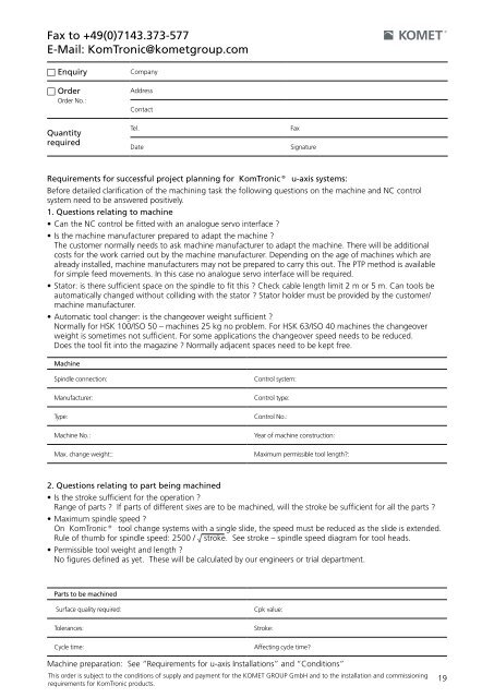
Fax to +49(0)7143.373-577<br />
E-Mail: KomTronic@kometgroup.com<br />
n Enquiry Company<br />
n Order<br />
Order No.:<br />
Quantity<br />
required<br />
Requirements for successful project planning for <strong>KomTronic®</strong> u-axis <strong>system</strong>s:<br />
Before detailed clarification of the machining task the following questions on the machine and NC control<br />
<strong>system</strong> need to be answered positively.<br />
1. Questions relating to machine<br />
• Can the NC control be fitted with an analogue servo interface ?<br />
• Is the machine manufacturer prepared to adapt the machine ?<br />
The customer normally needs to ask machine manufacturer to adapt the machine. There will be additional<br />
costs for the work carried out by the machine manufacturer. Depending on the age of machines which are<br />
already installed, machine manufacturers may not be prepared to carry this out. The PTP method is available<br />
for simple feed movements. In this case no analogue servo interface will be required.<br />
• Stator: is there sufficient space on the spindle to fit this ? Check cable length limit 2 m or 5 m. Can tools be<br />
automatically changed without colliding with the stator ? Stator holder must be provided by the customer/<br />
machine manufacturer.<br />
• Automatic tool changer: is the changeover weight sufficient ?<br />
Normally for HSK 100/ISO 50 – machines 25 kg no problem. For HSK 63/ISO 40 machines the changeover<br />
weight is sometimes not sufficient. For some applications the changeover speed needs to be reduced.<br />
Does the tool fit into the magazine ? Normally adjacent spaces need to be kept free.<br />
Machine<br />
Spindle connection: Control <strong>system</strong>:<br />
Manufacturer: Control type:<br />
Type: Control No.:<br />
Machine No.: Year of machine construction:<br />
Max. change weight:: Maximum permissible tool length?:<br />
2. Questions relating to part being machined<br />
• Is the stroke sufficient for the operation ?<br />
Range of parts ? If parts of different sixes are to be machined, will the stroke be sufficient for all the parts ?<br />
• Maximum spindle speed ?<br />
On <strong>KomTronic®</strong> tool change <strong>system</strong>s with a single slide, the speed must be reduced as the slide is extended.<br />
Rule of thumb for spindle speed: 2500 / √ stroke. See stroke – spindle speed diagram for tool heads.<br />
• Permissible tool weight and length ?<br />
No figures defined as yet. These will be calculated by our engineers or trial department.<br />
Parts to be machined<br />
Address<br />
Contact<br />
Tel. Fax<br />
Date Signature<br />
Surface quality required: Cpk value:<br />
Tolerances: Stroke:<br />
Cycle time: Affecting cycle time?<br />
Machine preparation: See “Requirements for u-axis Installations” and “Conditions”<br />
This order is subject to the conditions of supply and payment for the <strong>KOMET</strong> GROUP GmbH and to the installation and commissioning<br />
requirements for KomTronic products.<br />
19