Architectural_Design_with_SketchUp

You also want an ePaper? Increase the reach of your titles
YUMPU automatically turns print PDFs into web optimized ePapers that Google loves.
<strong>Architectural</strong> <strong>Design</strong> <strong>with</strong> <strong>SketchUp</strong>
<strong>Architectural</strong> <strong>Design</strong> <strong>with</strong> <strong>SketchUp</strong><br />
Component-Based Modeling, Plugins,<br />
Rendering, and Scripting<br />
Alexander C. Schreyer
Cover design: David Riedy<br />
Cover illustrations: (front and back) Courtesy of Alexander C. Schreyer<br />
This book is printed on acid-free paper.<br />
Copyright © 2013 by John Wiley & Sons, Inc. All rights reserved.<br />
Published by John Wiley & Sons, Inc., Hoboken, New Jersey.<br />
Published simultaneously in Canada.<br />
No part of this publication may be reproduced, stored in a retrieval system, or transmitted in any form or by any<br />
means, electronic, mechanical, photocopying, recording, scanning, or otherwise, except as permitted under Section<br />
107 or 108 of the 1976 United States Copyright Act, <strong>with</strong>out either the prior written permission of the Publisher,<br />
or authorization through payment of the appropriate per-copy fee to the Copyright Clearance Center, Inc., 222<br />
Rosewood Drive, Danvers, MA 01923, 978-750-8400, fax 978-646-8600, or on the web at www.copyright.com.<br />
Requests to the Publisher for permission should be addressed to the Permissions Department, John Wiley & Sons, Inc.,<br />
111 River Street, Hoboken, NJ 07030, 201-748-6011, fax 201-748-6008, or online at www.wiley.com/go/permissions.<br />
Limit of Liability/Disclaimer of Warranty: While the publisher and author have used their best efforts in preparing this<br />
book, they make no representations or warranties <strong>with</strong> respect to the accuracy or completeness of the contents of<br />
this book and specifically disclaim any implied warranties of merchantability or fitness for a particular purpose. No<br />
warranty may be created or extended by sales representatives or written sales materials. The advice and strategies<br />
contained herein may not be suitable for your situation. You should consult <strong>with</strong> a professional where appropriate.<br />
Neither the publisher nor the author shall be liable for damages arising herefrom.<br />
For general information on our other products and services, or technical support, please contact our Customer<br />
Care Department <strong>with</strong>in the United States at 800-762-2974, outside the United States at 317-572-3993 or fax<br />
317-572-4002.<br />
Wiley publishes in a variety of print and electronic formats and by print-on-demand. Some material included <strong>with</strong><br />
standard print versions of this book may not be included in e-books or in print-on-demand. If this book refers to<br />
media such as a CD or DVD that is not included in the version you purchased, you may download this material at<br />
http://booksupport.wiley.com. For more information about Wiley products, visit our Web site at www.wiley.com.<br />
Library of Congress Cataloging-in-Publication Data:<br />
Schreyer, Alexander (Alexander C.)<br />
<strong>Architectural</strong> <strong>Design</strong> <strong>with</strong> <strong>SketchUp</strong>: Component-based modeling, plugins, rendering, and scripting / Alexander<br />
Schreyer.<br />
p. cm.<br />
Includes index.<br />
ISBN 978-1-118-12309-6 (pbk.), ISBN 978-1-118-37652-2 (ebk.); ISBN 978-1-118-37654-6 (ebk.); ISBN 978-1-118-<br />
38596-8 (ebk.); ISBN 978-1-118-38597-5 (ebk.); ISBN 978-1-118-38598-2 (ebk.); ISBN 978-1-118-56787-6 (ebk.);<br />
ISBN 978-1-118-56776-0 (ebk.)<br />
1. Computer graphics. 2. <strong>SketchUp</strong>. 3. Three-dimensional display systems. 4. Engineering graphics. I. Title.<br />
T385.S3347 2013<br />
006.6’8—dc23<br />
2012007297<br />
Printed in the United States of America<br />
10 9 8 7 6 5 4 3 2 1
For my father, Gerhard
Contents<br />
Acknowledgments . . . . . . . . . . . . . . . . . . . . . . . . . . . . . . . . . . ix<br />
Chapter 1: Introduction . . . . . . . . . . . . . . . . . . . . . . . . . . . . . . . 1<br />
About This Book . . . . . . . . . . . . . . . . . . . . . . . . . . . . . . . . . 1<br />
3D for All. . . . . . . . . . . . . . . . . . . . . . . . . . . . . . . . . . . . .5<br />
How Does <strong>SketchUp</strong> Fit into the <strong>Design</strong>er’s Toolbox? . . . . . . . . . . . . . . .6<br />
Windows or Mac, Free or Pro? . . . . . . . . . . . . . . . . . . . . . . . . . . 7<br />
How This Book Works . . . . . . . . . . . . . . . . . . . . . . . . . . . . . . 9<br />
Let’s Go! . . . . . . . . . . . . . . . . . . . . . . . . . . . . . . . . . . . . 10<br />
Chapter 2: A <strong>SketchUp</strong> Refresher . . . . . . . . . . . . . . . . . . . . . . . . 11<br />
Let’s Get Started!. . . . . . . . . . . . . . . . . . . . . . . . . . . . . . . . 11<br />
Interface and Program Setup . . . . . . . . . . . . . . . . . . . . . . . . . . 12<br />
Adjusting Preferences . . . . . . . . . . . . . . . . . . . . . . . . . . . . 15<br />
Working <strong>with</strong> Templates . . . . . . . . . . . . . . . . . . . . . . . . . . . . 17<br />
Setting Units and Fonts . . . . . . . . . . . . . . . . . . . . . . . . . . . 18<br />
Adding Components . . . . . . . . . . . . . . . . . . . . . . . . . . . . 20<br />
Views . . . . . . . . . . . . . . . . . . . . . . . . . . . . . . . . . . . . 20<br />
Completed Template . . . . . . . . . . . . . . . . . . . . . . . . . . . . 21<br />
<strong>SketchUp</strong>’s Tool Set. . . . . . . . . . . . . . . . . . . . . . . . . . . . . . . 22<br />
Navigating the 3D Model . . . . . . . . . . . . . . . . . . . . . . . . . . 22<br />
Accurate Modeling . . . . . . . . . . . . . . . . . . . . . . . . . . . . . 24<br />
Groups and Components . . . . . . . . . . . . . . . . . . . . . . . . . . 29<br />
Applying Materials . . . . . . . . . . . . . . . . . . . . . . . . . . . . . 39<br />
Other Tools . . . . . . . . . . . . . . . . . . . . . . . . . . . . . . . . . 43<br />
<strong>SketchUp</strong> Best Practices . . . . . . . . . . . . . . . . . . . . . . . . . . . . 45<br />
Chapter 3: Using <strong>SketchUp</strong> to Inform Your <strong>Design</strong>s . . . . . . . . . . . . .48<br />
Group- and Component-Based Modeling . . . . . . . . . . . . . . . . . . . 48<br />
Effective Use of Groups and Components . . . . . . . . . . . . . . . . . . 49<br />
Modeling <strong>with</strong> Manufacture in Mind . . . . . . . . . . . . . . . . . . . . 54<br />
Using Dynamic Components to Your Advantage . . . . . . . . . . . . . . . . 63<br />
Where Does <strong>SketchUp</strong> Fit into the BIM Workflow? . . . . . . . . . . . . . . . 71<br />
Geo-Based Modeling . . . . . . . . . . . . . . . . . . . . . . . . . . . . . . 77<br />
Chapter 4: Using Plugins Effectively . . . . . . . . . . . . . . . . . . . . . . .80<br />
What Does a Plugin Do? . . . . . . . . . . . . . . . . . . . . . . . . . . . . 80<br />
Getting Plugins . . . . . . . . . . . . . . . . . . . . . . . . . . . . . . . 81<br />
Installing Plugins. . . . . . . . . . . . . . . . . . . . . . . . . . . . . . . 82<br />
Uninstalling and Organizing Plugins . . . . . . . . . . . . . . . . . . . . . 84<br />
vi
Contents<br />
Plugin Overview . . . . . . . . . . . . . . . . . . . . . . . . . . . . . . . . 85<br />
Plugins for General Modeling . . . . . . . . . . . . . . . . . . . . . . . . 86<br />
Plugins for <strong>Architectural</strong> Modeling. . . . . . . . . . . . . . . . . . . . . . 99<br />
Plugins for Digital Fabrication . . . . . . . . . . . . . . . . . . . . . . . .103<br />
Plugins for Data Integration and Exchange . . . . . . . . . . . . . . . . . 114<br />
Plugins for Animation and Presentation . . . . . . . . . . . . . . . . . . . 116<br />
Plugins for Analysis . . . . . . . . . . . . . . . . . . . . . . . . . . . . .120<br />
Chapter 5: Rendering in <strong>SketchUp</strong> . . . . . . . . . . . . . . . . . . . . . . . 129<br />
Let’s Get Visual! . . . . . . . . . . . . . . . . . . . . . . . . . . . . . . . .129<br />
What Is Already in <strong>SketchUp</strong>? . . . . . . . . . . . . . . . . . . . . . . . .129<br />
Overview of Rendering Methods . . . . . . . . . . . . . . . . . . . . . . . .135<br />
What Is Photorealistic Rendering? . . . . . . . . . . . . . . . . . . . . . .136<br />
Rendering Techniques . . . . . . . . . . . . . . . . . . . . . . . . . . . 141<br />
Rendering Software . . . . . . . . . . . . . . . . . . . . . . . . . . . . . .141<br />
Set up Kerkythea and Create a Rendering . . . . . . . . . . . . . . . . . 145<br />
Setting Up Rendering Components. . . . . . . . . . . . . . . . . . . . . . 155<br />
Modeling . . . . . . . . . . . . . . . . . . . . . . . . . . . . . . . . . .155<br />
Environment. . . . . . . . . . . . . . . . . . . . . . . . . . . . . . . . 160<br />
Lighting . . . . . . . . . . . . . . . . . . . . . . . . . . . . . . . . . . .168<br />
Materials . . . . . . . . . . . . . . . . . . . . . . . . . . . . . . . . . .186<br />
Objects . . . . . . . . . . . . . . . . . . . . . . . . . . . . . . . . . . .206<br />
Rendering Tips . . . . . . . . . . . . . . . . . . . . . . . . . . . . . . . . .223<br />
Making Renderings Presentable . . . . . . . . . . . . . . . . . . . . . . . .224<br />
Combining <strong>SketchUp</strong> Output and Rendered Output in Photoshop. . . . . 225<br />
Other Methods . . . . . . . . . . . . . . . . . . . . . . . . . . . . . . .227<br />
Chapter 6: Creating Geometry Using Ruby Scripting . . . . . . . . . . . 229<br />
Why Computational Geometry? . . . . . . . . . . . . . . . . . . . . . . . .229<br />
Setting Up Your Computer . . . . . . . . . . . . . . . . . . . . . . . . . . .231<br />
Installing the Ruby Code Editor Plugin . . . . . . . . . . . . . . . . . . . 233<br />
Other Options: More Plugins and External Editors . . . . . . . . . . . . . .235<br />
Intro to Ruby and the <strong>SketchUp</strong> API . . . . . . . . . . . . . . . . . . . . . .235<br />
How Does Ruby Work? . . . . . . . . . . . . . . . . . . . . . . . . . . .236<br />
What’s in <strong>SketchUp</strong>’s Ruby API? . . . . . . . . . . . . . . . . . . . . . . 241<br />
Links to Further Reading. . . . . . . . . . . . . . . . . . . . . . . . . . 244<br />
Creating Geometry <strong>with</strong> Ruby . . . . . . . . . . . . . . . . . . . . . . . . .245<br />
Lots of Boxes . . . . . . . . . . . . . . . . . . . . . . . . . . . . . . . .246<br />
Lots of Boxes <strong>with</strong> Color. . . . . . . . . . . . . . . . . . . . . . . . . . 248<br />
Creating a Small City . . . . . . . . . . . . . . . . . . . . . . . . . . . .250<br />
Randomizing Extrusions . . . . . . . . . . . . . . . . . . . . . . . . . . 251<br />
Using Formulas for Patterned Panels. . . . . . . . . . . . . . . . . . . . 252<br />
Plotting Data from Text Files. . . . . . . . . . . . . . . . . . . . . . . . 254<br />
Saving Vertices to a Text File. . . . . . . . . . . . . . . . . . . . . . . . 257<br />
vii
Contents<br />
Transformations Change Things Up. . . . . . . . . . . . . . . . . . . . . . 258<br />
Lots of Boxes Using Components . . . . . . . . . . . . . . . . . . . . . .260<br />
Building a Curved Wall . . . . . . . . . . . . . . . . . . . . . . . . . . .261<br />
Placing Components on Faces . . . . . . . . . . . . . . . . . . . . . . . 262<br />
Randomizing Everything. . . . . . . . . . . . . . . . . . . . . . . . . . 265<br />
Attracted to Attractors . . . . . . . . . . . . . . . . . . . . . . . . . . . . .266<br />
Coloring Faces by Proximity . . . . . . . . . . . . . . . . . . . . . . . . .267<br />
Scaling Objects by Proximity. . . . . . . . . . . . . . . . . . . . . . . . 269<br />
Solar-Responsive <strong>Design</strong>. . . . . . . . . . . . . . . . . . . . . . . . . . 271<br />
What Else Is Possible <strong>with</strong> This?. . . . . . . . . . . . . . . . . . . . . . . . 273<br />
Some Pitfalls and Things to Watch Out For . . . . . . . . . . . . . . . . . . .274<br />
Appendices<br />
Appendix A: <strong>SketchUp</strong> Quick Reference Cards . . . . . . . . . . . . . . . 275<br />
Appendix B: Ruby Class and Method Reference . . . . . . . . . . . . . . 280<br />
Appendix C: <strong>SketchUp</strong> API Class and Method Reference . . . . . . . . . 282<br />
Appendix D: Creating Your Own Plugins . . . . . . . . . . . . . . . . . . . 291<br />
RBZ Plugin File Structure. . . . . . . . . . . . . . . . . . . . . . . . . . 291<br />
Plugin Template Structure . . . . . . . . . . . . . . . . . . . . . . . . . 291<br />
Appendix E: Dynamic Component Function Reference. . . . . . . . . 294<br />
Index . . . . . . . . . . . . . . . . . . . . . . . . . . . . . . . . . . . . . . . . . . 297<br />
viii
Acknowledgments<br />
Having taught <strong>SketchUp</strong> to varied audiences of eager students, I should start my acknowledgments<br />
<strong>with</strong> exactly those students whose many questions and creative ideas have inspired<br />
me not only to look deeper into the software, but also to put this text down on paper. Keep<br />
pushing the boundaries of the third dimension in your work!<br />
An amazing product can often be judged by the community that develops around it.<br />
<strong>SketchUp</strong> has always been a small, yet transformative piece of software, whose simplicity and<br />
power have enthralled users for many years. This has created a large user community, which<br />
in forums, blogs, at user meetings, and other venues has—often passionately—taken to using<br />
it to design whatever came to their creative minds and educating others in how to use it to<br />
realize their ideas. I would like to hereby acknowledge that community for its devotion, support<br />
and inventiveness, and am <strong>with</strong> this book paying forward any support they ever gave me.<br />
Among the makers of <strong>SketchUp</strong> I would like to foremost thank <strong>SketchUp</strong> product manager<br />
John Bacus and product evangelist Aidan Chopra for their feedback whenever I had a<br />
request—and of course for the great time I had in Boulder.<br />
This book would not have been possible <strong>with</strong>out the support and feedback from acquisitions<br />
editor Paul Drougas at John Wiley & Sons. This being my first book endeavor, I am<br />
still in awe of the amount of work that the editorial team puts into a publication like this. In<br />
particular, I would like to acknowledge production editor Nancy Cintron’s tireless suggestions<br />
of edits and revisions as well as copyeditor Ginny Carroll’s and editorial assistant Mike New’s<br />
help in this process. Judging by the editing initials in the manuscript, it passed through many<br />
more hands whose anonymous work I hereby gratefully acknowledge.<br />
Finally—and most importantly—I would like to thank the love of my life, my wonderful<br />
wife Peggi, and our two girls, Sophia and Mackenzie, for their love, tremendous encouragement,<br />
and support, as well as their patience <strong>with</strong> me while I was preparing the manuscript.<br />
I couldn’t have done it <strong>with</strong>out them! They are, together <strong>with</strong> my mother and my brother,<br />
the source of all my strength and joy.<br />
ix
Chapter 1<br />
Introduction<br />
In my years of teaching <strong>SketchUp</strong>, as well as other Computer-<br />
Aided <strong>Design</strong> (CAD) and Building Information Modeling (BIM)<br />
software, I have seen very proficient users of this software.<br />
Students and professionals take easily to <strong>SketchUp</strong>, and, before<br />
long, some of them produce very detailed building models and<br />
professional-grade renderings. But I have also found that too<br />
many people don’t go beyond the basics and believe that some<br />
of the advanced modeling (or good-quality photorealistic rendering)<br />
needs to be done using other software. Very often, they<br />
painstakingly pick up that other software only to find that it is<br />
too complex, which likewise leaves them unable to do what<br />
they wanted.<br />
Sometimes even advanced users of <strong>SketchUp</strong> master one aspect of the software (photorealistic<br />
rendering, for example) but are completely unaware of the power that <strong>SketchUp</strong><br />
holds in other areas—Dynamic Components and Ruby scripting are good examples. As you<br />
will find out in this book, <strong>SketchUp</strong> is a very powerful design and 3D modeling tool. Some<br />
of its core features—for example, its extendibility <strong>with</strong> plugins—make it flexible enough to<br />
be useful for a variety of disciplines. The large number of high-quality plugins that are available<br />
for <strong>SketchUp</strong> these days bears powerful witness to this.<br />
This book attempts to help the basic to intermediate user make the leap from simply<br />
creating “something” in <strong>SketchUp</strong> to using it as a powerful design tool. While it contains<br />
some more involved topics (such as photorealistic rendering, Dynamic Components, and Ruby<br />
scripting), it provides a clear learning path that takes you through easy-to-follow examples<br />
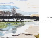
to a thorough understanding of the core topics. Figure 1.1 shows an example of how one<br />
could use Ruby scripting to create geometry, then render the scene using a photorealistic<br />
rendering software and finally “dress-up” the image as a watercolor painting.<br />
About This Book<br />
Each chapter in this book presents a different <strong>SketchUp</strong> use in sufficient detail to get you<br />
started and working quickly. Interspersed <strong>with</strong> the text are many step-by-step examples, tips,<br />
and in-depth articles. At the end of each chapter, you will also find a collection of activities<br />
that you can undertake to try out new skills that you just learned.<br />
1
<strong>Architectural</strong> <strong>Design</strong> <strong>with</strong> <strong>SketchUp</strong><br />
Figure 1.1: Watercolor of a rendering of script-generated panels<br />
Chapter 2, which follows this introductory chapter, brings every reader up to speed. Its<br />
purpose as a “<strong>SketchUp</strong> Refresher” is to review some basic modeling techniques and teach<br />
good practices for modeling and software use. While many readers will already have some<br />
knowledge of <strong>SketchUp</strong> through introductory books or video tutorials, this chapter encompasses<br />
enough variety to be useful for everyone, independent of their skill level.<br />
Chapter 3 uses <strong>SketchUp</strong> not only as a modeling tool but also as a tool to inform your<br />
designs. In this chapter, you will learn more ways to employ <strong>SketchUp</strong> as an aid in your design<br />
process. Examples of this are creating component-based models, using Dynamic Components,<br />
and geo-based modeling. One section also looks at how <strong>SketchUp</strong> can fit into a BIM-based<br />
architectural design process.<br />
Chapter 4 leads you into the wide field of <strong>SketchUp</strong> plugins and their uses. After an<br />
introductory section on finding and installing plugins, many individual plugins are discussed.<br />
Those small software add-ons to <strong>SketchUp</strong> provide tools for general modeling, such as drawing<br />
splines and lofting curves; tools for architectural design, such as stair making and wood<br />
framing; and tools for digital fabrication that will help you prepare your model for 2D and<br />
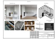
3D digital printing and assembly. (See Figure 1.2 for an example of a fabricated <strong>SketchUp</strong><br />
model). Furthermore, there are plugins for data integration that can import or export data<br />
such as LIDAR laser-scan points, plugins for animation and presentation that add object animation<br />
or serve as helpers for creating animations and walk-throughs using <strong>SketchUp</strong>, and,<br />
2
Chapter 1 Introduction<br />
finally, plugins for analysis, which provide analytical tools—mainly from the fields of building<br />
energy analysis and green building.<br />
Chapter 5 introduces photorealistic rendering and covers all aspects of rendering in detail<br />
(see Figure 1.3). This chapter was written to be as independent of your actual choice of<br />
rendering software as possible, thus providing a useful resource no matter which software<br />
you download or buy. As part of this chapter, you will learn about modeling for rendering,<br />
lighting, sky environment, materials, and objects, as well as how to edit and modify renderings<br />
using image-editing software.<br />
Figure 1.2: Infrared photography house model made in <strong>SketchUp</strong> and physically built using plugins<br />
3
<strong>Architectural</strong> <strong>Design</strong> <strong>with</strong> <strong>SketchUp</strong><br />
The final chapter in this book (Chapter 6) introduces you to the exciting field of computational<br />
geometry in <strong>SketchUp</strong>. This chapter presents Ruby Script examples that create<br />
undulating brick walls, solar-responsive facades, attractor-based colorful building designs,<br />
and other fun ways to create geometry in <strong>SketchUp</strong> <strong>with</strong>out excessive use of the mouse (see<br />
Figure 1.4). Most of the script examples accomplish their tasks in just a few lines of code,<br />
and all are a good introduction to both the Ruby scripting language and the general field of<br />
computational geometry.<br />
Figure 1.3: Glasses and liquid, rendered in <strong>SketchUp</strong><br />
Figure 1.4: A grassy hill made in <strong>SketchUp</strong><br />
4
Chapter 1 Introduction<br />
As you will see in the chapters that follow, this book is intended to serve as a textbook<br />
as well as a desk reference. It was written to convey the presented material in a thorough yet<br />
easy-to-follow manner. It also covers common tasks using a “cookbook” approach, which<br />
allows you to simply copy the procedure to get a satisfactory result or modify it according<br />
to your individual needs.<br />
In addition to reading this book, keep an eye on its companion website, which features<br />
blog posts, links, videos, and discussions related to this book. Web links will be frequently<br />
updated there and new ones added as new software is released.<br />
This book’s companion sites can be found here:<br />
www.sketchupfordesign.com—Author’s companion site.<br />
www.wiley.com/go/schreyer—Companion site for students and instructors.<br />
3D for All<br />
Because <strong>SketchUp</strong> is not domain-specific, it has found a following<br />
<strong>with</strong> professionals and enthusiasts from many disciplines. This<br />
is why you will find <strong>SketchUp</strong> mentioned in discussions not only<br />
by architects, landscape architects, urban planners, engineers,<br />
construction professionals, woodworkers, and timber framers<br />
but also by robot builders, artists, sculptors, model-plane<br />
builders, paper-plane builders, mapmakers, historians, 3D game<br />
developers, and movie set designers (just to mention a few).<br />
The techniques in this book are applicable to a variety of<br />
disciplines. Although many examples come from architecture or<br />
construction, some are from other disciplines (e.g., landscape<br />
design and interior design). Whatever your background is, feel<br />
free to take the examples that are presented here and adapt<br />
them to your discipline. (See Figure 1.5 for a non-traditional use<br />
of <strong>SketchUp</strong>). The techniques you learn will be equally useful.<br />
Taking this one step further, I can even say that I can’t think of anyone who should not<br />
be using <strong>SketchUp</strong>. Living in a three-dimensional world and dealing <strong>with</strong> three-dimensional<br />
objects, everyone has the need at some point to model and visualize in three-dimensional space.<br />
Consider this hypothetical situation: You want to build a deck in your backyard and need to<br />
explain to the builder how it should look. Another example is a physicist who needs to explain<br />
a lab setup in a presentation. Far too often we resort to 2D representations of our thoughts<br />
(the classic floor plan, for example), which leaves too much unknown and unexplorable.<br />
5
<strong>Architectural</strong> <strong>Design</strong> <strong>with</strong> <strong>SketchUp</strong><br />
Admittedly, many people are not trained in hand-sketching in 3D, which often leads to<br />
poor visualizations of things that can actually be quite interesting when presented right. That<br />
is where <strong>SketchUp</strong> shines. Its 3D modeling capabilities and its ease of use make it a simple<br />
yet very powerful tool for anyone to give shape to their thoughts.<br />
Figure 1.5: Rendered 3D QR-code model<br />
How Does <strong>SketchUp</strong> Fit into the <strong>Design</strong>er’s Toolbox?<br />
As a student or professional, you likely already have assembled a sizable software “tool chest”<br />
by now. Depending on your discipline, this might include office software, CAD software,<br />
image-editing software, print layout software, analysis software (for energy or structural<br />
analysis, for example), coordination tools, and many others.<br />
The free version of <strong>SketchUp</strong> fits into this collection very well. Depending on your needs<br />
and knowledge of the software, you can use it as an early design tool—after all, as its name<br />
indicates, it was developed for 3D “sketching.” You can also use it for the complete design<br />
process from initial stages to a finished product (whatever that may be). <strong>SketchUp</strong> Pro broadens<br />
this even further by providing layout and documentation abilities and other professionaloriented<br />
tools.<br />
6
Chapter 1 Introduction<br />
<strong>SketchUp</strong> works well <strong>with</strong> other software. 3D models from <strong>SketchUp</strong> can often be directly<br />
opened in other software, making data exchange easy. Even if that isn’t available, <strong>SketchUp</strong>’s<br />
built-in file exchange options allow you to export a 3D model in a variety of formats.<br />
If <strong>SketchUp</strong> is already part of your tool set, then it is the best use of your time to expand<br />
on the skill set that you have developed and deepen your knowledge of this software. This<br />
book provides you many avenues to do so.<br />
Windows or Mac, Free or Pro?<br />
<strong>SketchUp</strong> comes in two flavors: free and Pro. It is also multiplatform software, which means<br />
it is available for both Windows and Mac computers.<br />
In the free version, a user can do almost everything that is available in the Pro version. The<br />
main differences are that the free version does not include the more professionally oriented<br />
DWG/DXF file exchange options (plus some others), it also does not include the ability to create<br />
Dynamic Components (and report them), and it does not include Pro’s excellent Solid Tools.<br />
Looking at the Pro version, you will find that it comes <strong>with</strong> two additional pieces of software:<br />
LayOut, which is a tool for drawing preparation and presentations based on <strong>SketchUp</strong><br />
models, and Style Builder, a program that lets you make your own hand-drawn styles based<br />
on pencil-sketched lines.<br />
While the free version can be downloaded by anyone from <strong>SketchUp</strong>’s website, the Pro<br />
version is moderately priced (under $500 in the U.S.) and can be purchased from the website as<br />
well. Both versions are currently available in twelve languages (Traditional Chinese, Simplified<br />
Chinese, Dutch, English, French, German, Italian, Japanese, Korean, Brazilian Portuguese,<br />
Spanish, and Russian), which gives this software global reach. At this point, qualified students<br />
(in the U.S.) can get a time-limited license to use <strong>SketchUp</strong> Pro for $45.<br />
Depending on your needs, you have to decide which version is right for you. For almost<br />
all of this book’s content, it is not necessary to have the Pro version; photorealistic rendering,<br />
many plugins, and scripting work perfectly well in the free version. This book, therefore,<br />
offers a cost-efficient entry into relevant and current topics (such as 3D modeling, rendering,<br />
and computational geometry). Because <strong>SketchUp</strong> comes in a free version, it provides an<br />
opportunity to use advanced software approaches <strong>with</strong>out having to resort to costly software.<br />
Nevertheless, some Pro tools are covered in this book (e.g., creating a Dynamic Component<br />
and using Solid Tools). Whenever a chapter in this book mentions a Pro tool, it is visually presented<br />
as a “Pro Only” section.<br />
Pro Only sections look like this.<br />
PRO ONLY<br />
While all of this book’s illustrations have been created using the Windows version of<br />
<strong>SketchUp</strong>, the tasks and tutorials are similarly usable <strong>with</strong> the Mac version. Menus and dialogs<br />
generally look the same and are in the same location on both platforms. There are minor<br />
7
<strong>Architectural</strong> <strong>Design</strong> <strong>with</strong> <strong>SketchUp</strong><br />
user-interface differences, but those are easy to figure out. Consult <strong>SketchUp</strong>’s help system<br />
if you run into trouble.<br />
About <strong>SketchUp</strong>’s Transition from Google to Trimble<br />
On April 26th, 2012, Google (who had bought the <strong>SketchUp</strong> software in 2006 from @Last,<br />
its original makers) announced that they sold <strong>SketchUp</strong> to Trimble, a company known<br />
for AEC (architecture, engineering, and construction) technology and software. The<br />
announcement came <strong>with</strong> assurances from both companies that <strong>SketchUp</strong> will remain<br />
available in a free version as well as a Pro version and that software development will<br />
increase in the future. Given the transition to Trimble, some changes have to be expected,<br />
but for a foreseeable time, the largest extent of those changes will be differing URLs and<br />
documentation changes.<br />
Fortunate for the user community, this transition infuses energy into <strong>SketchUp</strong> development<br />
and it is very likely that new features will be created soon while its core functionality<br />
(as described in this book) will be retained.<br />
Keep an eye on the companion website (www.sketchupfordesign.com) during this<br />
period of transition. I will post updated URLs and announcements of new features as<br />
they become public. In the meantime, this book will use currently known URLs and the<br />
“Google” name where relevant to current installations.<br />
It is a good idea to stay up to date <strong>with</strong> <strong>SketchUp</strong>. In addition to this book’s companion<br />
website, bookmark the following sites to help you <strong>with</strong> this:<br />
www.sketchup.com—The official home of <strong>SketchUp</strong>. You can download the latest free<br />
version or buy the Pro version here.<br />
http://sketchupdate.blogspot.com—The official <strong>SketchUp</strong> blog—a great source for<br />
updates, tutorials, and tips.<br />
http://support.google.com/sketchup—<strong>SketchUp</strong>’s help system. If you get stuck, go<br />
here first!<br />
www.alexschreyer.net—My personal blog where I frequently post about <strong>SketchUp</strong><br />
and other AEC software.<br />
@alexschreyer and @sketchupplugins—My Twitter handles under which I post news<br />
and links about <strong>SketchUp</strong> and AEC software.<br />
8
Chapter 1 Introduction<br />
How This Book Works<br />
One way to use this book is linearly as a learning tool by moving from chapter to chapter.<br />
This method builds your skill set gradually and allows you to logically approach each subject.<br />
You may also want to use it as a desk reference, or you might be interested just in individual<br />
chapters. In these cases, make use of the index and the appendices.<br />
Some conventions in this book:<br />
NN<br />
Whenever I mention a “window” (e.g., the Materials window), this means the dialog<br />
window that can be accessed from <strong>SketchUp</strong>’s Window menu.<br />
NN<br />
Other dialogs that open when the user clicks on something are commonly called “dialog”<br />
in the text.<br />
NN<br />
Menu locations are typically presented in this format: File k Open . . .<br />
NN<br />
NN<br />
Any toolbars mentioned in the text can be opened from the View k Toolbars menu in<br />
<strong>SketchUp</strong>. Plugins often install their own toolbars. Those will, of course, not be available<br />
until a plugin has been installed.<br />
Following are some Mac-specific differences:<br />
NN<br />
NN<br />
NN<br />
<strong>SketchUp</strong>’s preferences cannot be found under the Window menu item, but instead<br />
are under the <strong>SketchUp</strong> menu.<br />
Toolbars are called “Tool Palettes.”<br />
Instead of right-clicking to bring up the context-menu, you can left-click the mouse<br />
while holding the Control key.<br />
9
<strong>Architectural</strong> <strong>Design</strong> <strong>with</strong> <strong>SketchUp</strong><br />
Let’s Go!<br />
It’s time to explore the world in the third dimension. Enjoy your modeling endeavors!<br />
10
Chapter 2<br />
A <strong>SketchUp</strong> Refresher<br />
This chapter reviews some of <strong>SketchUp</strong>’s basic techniques. You’ll also learn about customizing<br />
the software environment and adjusting settings to help you <strong>with</strong> your daily tasks.<br />
Key Topics:<br />
NN<br />
NN<br />
NN<br />
NN<br />
NN<br />
NN<br />
NN<br />
NN<br />
NN<br />
Where to get help <strong>with</strong> <strong>SketchUp</strong><br />
Program interface and workspace customization<br />
Program and model preferences<br />
Working <strong>with</strong> templates<br />
Navigating <strong>SketchUp</strong>’s 3D workspace<br />
Aids for accurate modeling<br />
Groups and components<br />
Applying materials and using other common tools<br />
Best practices for working <strong>with</strong> <strong>SketchUp</strong><br />
Let’s Get Started!<br />
Before we look at any of the more advanced <strong>SketchUp</strong> techniques such as plugins, rendering,<br />
or even scripting, it should be helpful for any user to review in a short chapter some of the basic<br />
modeling techniques. This chapter therefore presents in a condensed fashion an overview of<br />
the interface and the modeling and editing tools, as well as best practices and usability hints.<br />
If you have no prior experience <strong>with</strong> <strong>SketchUp</strong> or would like to learn more about any of<br />
the basic topics, then my best recommendation is to get a copy of Aidan Chopra’s excellent<br />
<strong>SketchUp</strong> primer Google <strong>SketchUp</strong> 8 for Dummies (Wiley Publishing). It is a thorough reference<br />
not only for modeling <strong>with</strong> <strong>SketchUp</strong> but also for creating building models for the free<br />
3D world viewer Google Earth.<br />
Two further sources for help are built right into <strong>SketchUp</strong>. One is the official help documentation.<br />
You can access it through the Help menu item, which simply opens a browser<br />
window at the following URL (if you end up using it frequently, it might be a good idea to<br />
bookmark it in your browser):<br />
http://sketchup.google.com/support—<strong>SketchUp</strong>’s online help system.<br />
11
<strong>Architectural</strong> <strong>Design</strong> <strong>with</strong> <strong>SketchUp</strong><br />
Alternatively, you can turn on the Instructor feature by selecting Instructor from the Window<br />
menu. This opens (and keeps open) a window that displays a help page for the tool that is<br />
currently in use. For example, if you start using the Circle tool (by clicking on the Circle toolbar<br />
button, selecting Circle on the Draw menu, or simply hitting the C key on the keyboard),<br />
the Instructor shows the appropriate help, complete <strong>with</strong> a small animation. (See Figure 2.1)<br />
Figure 2.1: <strong>SketchUp</strong>’s Instructor window<br />
I also encourage you to visit this book’s companion website (www.sketchupfordesign.com) for<br />
an updated list of links to online resources. In addition, there are currently many discussion<br />
forums, wikis, and online video sites available that offer help for both beginners and advanced<br />
users. The most popular ones are:<br />
http://productforums.google.com/forum/#!forum/sketchup—Sketchup’s official<br />
help forum.<br />
http://forums.sketchucation.com—The SketchUcation forums, a user-based worldwide<br />
community.<br />
www.aidanchopra.com—Aidan’s companion site to his book, which contains many<br />
YouTube instructional videos.<br />
12<br />
Interface and Program Setup<br />
Once installed, <strong>SketchUp</strong> has a clean and rather empty appearance. The main portion of the<br />
screen is taken up by a large 3D-space work area in which only the ground plane (shown in<br />
solid green), sky (blue gradient), the three main axes, and a modeled person (included as a<br />
size reference) are visible.
Chapter 2 A <strong>SketchUp</strong> Refresher<br />
The person in <strong>SketchUp</strong>’s default template has historically been an employee from the<br />
<strong>SketchUp</strong> “crew.” For version 8, this is “Susan.” Earlier versions featured “Sang” and “Brad.”<br />
TIP<br />
Above the work area, the main toolbar buttons are nicely arranged on a toolbar called<br />
Getting Started. Figure 2.2 shows the workspace on Windows; Figure 2.3 shows the Mac<br />
equivalent.<br />
Figure 2.2: <strong>SketchUp</strong>’s workspace on Windows<br />
Figure 2.3: <strong>SketchUp</strong>’s workspace on the Mac<br />
13
<strong>Architectural</strong> <strong>Design</strong> <strong>with</strong> <strong>SketchUp</strong><br />
<strong>SketchUp</strong>’s numerous features can be accessed either through the screen menu, by clicking<br />
a button on the toolbars, or <strong>with</strong> keyboard shortcuts. As <strong>with</strong> many other programs, any toolbars<br />
that are not currently activated and visible can be displayed easily by selecting them from<br />
the View k Toolbars menu. You can see, for example, that an additional toolbar has already<br />
been activated in Figure 2.4. The toolbar called Large Tool Set has been activated and placed<br />
on the left side of the screen. It is always a good idea to have at least this one opened—even if<br />
no others are needed. In addition to the features in the standard Getting Started toolbar, it gives<br />
direct access to more navigation tools. However, it does not contain any of the 3D Warehouse<br />
or Google Earth links. If you need those, make sure you activate the Google toolbar.<br />
It is a good idea to develop a well-organized workspace in any software. In <strong>SketchUp</strong>,<br />
this means that if you find yourself using the same tools over and over (and you can’t access<br />
them using keyboard shortcuts, or you prefer toolbars), then you might want to display the<br />
appropriate toolbar and dock it on the screen in a convenient position. When you have<br />
arranged your workspace to your liking, don’t forget to click on Save Toolbar Positions in<br />
the View k Toolbars menu so that you can restore them if a problem occurs. (<strong>SketchUp</strong> has<br />
been known to occasionally—and out of the blue—rearrange your toolbars.)<br />
Figure 2.4: Working <strong>with</strong> <strong>SketchUp</strong>’s tools<br />
A very useful feature of <strong>SketchUp</strong>’s user interface is keyboard shortcuts. Even <strong>with</strong> the<br />
default settings, many tools can be accessed by pressing single keys. For example, the “L” key<br />
brings up the Line tool, “R” the Rectangle tool, and the spacebar the Select tool (and cancels<br />
any other currently active tool). An overview of the default keyboard shortcuts (and most<br />
tools) is given in Appendix A. As you can see in Figure 2.5, you can, in addition, assign keyboard<br />
shortcuts to any tool that is available in the menu structure. Just remember to export<br />
your keyboard settings (from <strong>with</strong>in the Preferences dialog) so that you have a backup available<br />
in case you need to reinstall <strong>SketchUp</strong>.<br />
14
Chapter 2 A <strong>SketchUp</strong> Refresher<br />
Figure 2.5: Keyboard shortcut preferences<br />
You can even assign a keyboard shortcut to plugin-supplied tools (as long as those tools<br />
have created their own menu items)!<br />
TIP<br />
Adjusting Preferences<br />
It is a good idea to spend some time tweaking all the options in <strong>SketchUp</strong>’s Preferences to<br />
your liking, especially if you are a frequent user. The following is a list of the main options<br />
(access the dialog under Window k Preferences), along <strong>with</strong> some tips:<br />
NN<br />
NN<br />
NN<br />
NN<br />
Applications—Select the path to your default image editor here (e.g., Adobe Photoshop).<br />
This makes it possible, for example, to tweak textures using that editor by opening images<br />
in the external editor directly from <strong>with</strong>in <strong>SketchUp</strong>.<br />
Compatibility—You can change your highlighting and mouse wheel preferences here.<br />
Drawing—You can select your click preferences here. For example, you have the choice<br />
of whether you want to draw a line by clicking and dragging or by clicking two points.<br />
Another useful feature is “Display crosshairs,” which always gives you an axis reference<br />
when you have a tool activated.<br />
Extensions—This shows a list of installed extensions (also called “plugins”). The default<br />
installation should display the Sandbox Tools together <strong>with</strong> a handful of others. You<br />
can install plugins here using the “Install Extension…” button. It is also possible to disable<br />
and enable installed plugins here by simply unchecking or checking the box next<br />
to the plugin’s name (a restart is often required). This sometimes becomes necessary<br />
when a plugin leads to crashes but you don’t want to uninstall it by removing its files.<br />
You will learn more about installing, using, and uninstalling plugins in Chapter 4.<br />
15
<strong>Architectural</strong> <strong>Design</strong> <strong>with</strong> <strong>SketchUp</strong><br />
NN<br />
NN<br />
Files—You can select locations on your hard disk for models, components, materials,<br />
and so on. These are set up by default in the main <strong>SketchUp</strong> installation directory, but<br />
sometimes it is quite convenient to also have a separate location where custom components<br />
are stored. A use case for this is a company in which several <strong>SketchUp</strong> installations<br />
need to access models located in central network storage (for details, see the note that<br />
follows this list).<br />
General—These are some miscellaneous settings of which the most important ones are<br />
“Create backup” (make sure this is checked in order to have a backup in case of a crash),<br />
“Auto-save” (set this to a short interval, such as every ten minutes), and “Automatically<br />
check for updates” (to be reminded when an update for <strong>SketchUp</strong> is available).<br />
TIP<br />
If you set up <strong>SketchUp</strong> to save backups, then there will be an SKB backup file saved in<br />
the same location where your SKP <strong>SketchUp</strong> file is saved. In case your main file becomes<br />
unusable, you can open the backup file directly <strong>with</strong> <strong>SketchUp</strong>. Just make sure you can<br />
see all files in the Open dialog by selecting “All files (*.*)” at the bottom of the dialog.<br />
NN<br />
NN<br />
NN<br />
NN<br />
OpenGL—These settings determine how the application graphics are being processed,<br />
which in turn determines how responsive <strong>SketchUp</strong> will be when you work <strong>with</strong> it. Unless<br />
you have a very old graphics card, make sure “Use hardware acceleration” is checked.<br />
This lets the graphics card do most of the display rendering and results in a responsive<br />
3D work environment. Also check the “Capabilities” table below these settings. It shows<br />
which capabilities of your graphics card have been found by <strong>SketchUp</strong>. It is always a good<br />
idea to select one of the rows where the anti-alias number is larger than zero so that<br />
lines on-screen don’t appear jagged. Experiment <strong>with</strong> these settings until you find the<br />
combination that works best for you.<br />
Shortcuts—As mentioned earlier, this allows you to add your own keyboard shortcuts.<br />
Template—You can select your default template here. To efficiently use a template in<br />
<strong>SketchUp</strong>, modify an empty file to your liking (including all settings in Window k Model<br />
Info, since they will be stored in the <strong>SketchUp</strong> file). You can even preload components<br />
and materials. Then save the file as a template (choose Save As Template. . . under the<br />
File menu) and preselect the file in this preference tab.<br />
Workspace—This allows you to change the size of the toolbar buttons and to reset the<br />
workspace.<br />
IN-DEPTH<br />
Using <strong>SketchUp</strong> on Multiple Computers<br />
If you use <strong>SketchUp</strong> on more than one computer, it might make sense to work from the<br />
same set of components, materials, textures, and so on. You can then, for example, create<br />
a collection of your own (or your company’s) custom components and materials that<br />
is synchronized across all the computers on which <strong>SketchUp</strong> is installed.<br />
16
Chapter 2 A <strong>SketchUp</strong> Refresher<br />
To accomplish this, there are two options:<br />
NN<br />
NN<br />
Work <strong>with</strong> a central repository. This option requires that you set up central data<br />
storage (e.g., network-attached storage or a server), where all files can be stored. Then<br />
all you need to do is go into <strong>SketchUp</strong>’s Preferences dialog and set all file locations<br />
to the appropriate folders on the network location. A drawback to this approach is<br />
that in order to access the stored data you need network access. Depending on your<br />
network connection and the size of your models, loading and saving might be slow.<br />
Work <strong>with</strong> a synchronized repository. This option is faster and safer because the<br />
repository is synchronized across all computers. It also ensures that the repository is<br />
available even when there is no network connection—for example, when you take<br />
your laptop on the road. The easiest way to make this option work is to sign up <strong>with</strong><br />
Dropbox (www.dropbox.com) or a similar service. Then download the client application<br />
for your system from Dropbox and set up a dedicated folder on your computer to<br />
hold all synchronized data (you may use it for more than just CAD files, of course). After<br />
you do this on all your computers that run <strong>SketchUp</strong>, go to <strong>SketchUp</strong>’s preferences and<br />
add the local (on your computer!) synchronized folder to the Files options. Thereafter,<br />
whenever you save, for example, a new component, Dropbox synchronizes it across<br />
all linked computers and, thus, it will be available wherever you work <strong>with</strong> <strong>SketchUp</strong>.<br />
With any of these methods, make sure you set up a good check-in/checkout system or<br />
use your network’s document storage provider’s history features so that a user can’t<br />
inadvertently overwrite somebody else’s files.<br />
Working <strong>with</strong> Templates<br />
Beyond the program’s settings, there are quite a few settings, data, and other items that are<br />
stored <strong>with</strong>in a <strong>SketchUp</strong> file (<strong>with</strong> an SKP extension) and therefore can be added to a template.<br />
This file is opened as the default empty file each time <strong>SketchUp</strong> starts and includes the following:<br />
NN<br />
NN<br />
NN<br />
NN<br />
NN<br />
NN<br />
NN<br />
NN<br />
All settings in the Model Info dialog and therefore (among others) dimension styles, text<br />
styles, and units<br />
Any entity placed in the 3D workspace (e.g., the person reference in the default template)<br />
The model’s geo-location<br />
Model credits<br />
Animation tabs and their views <strong>with</strong> all settings, such as View styles<br />
In-model components, materials, styles, layers, and so on<br />
Component attributes<br />
Plugin data if a plugin stores data <strong>with</strong>in the file<br />
As you can see from this list, many options might warrant tweaking and saving in a template.<br />
Also, because the template settings can’t be applied retroactively to an already existing<br />
file, it makes sense to preset template options before starting work in a file. Let’s look at<br />
setting some of the most useful options.<br />
17
<strong>Architectural</strong> <strong>Design</strong> <strong>with</strong> <strong>SketchUp</strong><br />
Setting Units and Fonts<br />
Figure 2.6 shows the Units settings. Depending on your profession or where you are in the<br />
world, you may want to select architectural units (e.g., 6f 5 ½g), decimal units (inches or feet<br />
or a metric unit—e.g., 2.5f or 3.2 m), engineering units (e.g., 100.623f), or, simply, fractional<br />
inches (e.g., 250 5 ⁄8g).<br />
Depending on the resolution of your work (are you using <strong>SketchUp</strong> for woodworking or<br />
to design houses?), make sure you preset both the length snapping and the angle snapping<br />
to values that make sense for you. Finally, set the precision to display a number of digits or a<br />
fraction that is appropriate for your work. Whatever you set here, rest assured that the software<br />
internally stores all numbers at a much higher degree of precision.<br />
Figure 2.6: Units settings in the Model Info dialog<br />
A great way to personalize your <strong>SketchUp</strong> output is by using a custom font for in-model text<br />
as well as leaders and dimensions. You can do that in the respective settings (see Figure 2.7<br />
for text setting options and Figure 2.8 for dimension settings).<br />
Figure 2.7: Text settings in the Model Info dialog<br />
18
Chapter 2 A <strong>SketchUp</strong> Refresher<br />
Figure 2.8: Dimension settings in the Model Info dialog<br />
Figure 2.9 shows a sample of various fonts: Windows’ standard Tahoma font as well as<br />
some custom technical fonts and a handwritten font. You can even create your own font<br />
using your own handwriting. Some Web resources are mentioned as follows.<br />
Figure 2.9: Using custom fonts in <strong>SketchUp</strong><br />
www.yourfonts.com—You can make your own font using this Web service. Alternatively,<br />
if you use a tablet device, look for software that allows you to do this by sketching the<br />
letters (Windows Tablet PCs come <strong>with</strong> such software preinstalled).<br />
www.dafont.com—This is only one of many websites that offer free and for-sale fonts.<br />
To install fonts, first download the desired font file (which can have any of these formats:<br />
TTF, OTF, or FON). Then, depending on your computer setup, either double-click the file<br />
and select Install or drop the file into the operating system’s Font folder (usually under<br />
Preferences or Control Panel).<br />
19
<strong>Architectural</strong> <strong>Design</strong> <strong>with</strong> <strong>SketchUp</strong><br />
Adding Components<br />
Think carefully which components you want to add to your <strong>SketchUp</strong> model because each<br />
one will increase the <strong>SketchUp</strong> file size. Having said that, it is always possible to purge unused<br />
file-space-heavy components and materials by using the options in the respective windows<br />
(see Figure 2.10 for the Components window);therefore, it might be a good idea to start<br />
<strong>with</strong> a larger file and then simply get rid of unused components later.<br />
Figure 2.10: Purging unused components<br />
Samples for preloaded components in architecture are people cutouts, a minimal set of<br />
trees and shrubbery, as well as any annotation elements that you might want to add to your<br />
model (e.g., a “north” arrow). While <strong>SketchUp</strong>’s default components are easily accessible<br />
through the component windows and therefore should not need to be loaded into a template,<br />
it’s a good idea to do this if you have created your own set of these components to<br />
give your models a more personal touch.<br />
One good example for this is your own person cutout (akin to the “Susan” figure that<br />
shipped <strong>with</strong> version 8 of <strong>SketchUp</strong>). One of <strong>SketchUp</strong>’s common criticisms is that its output can<br />
easily be identified as coming from <strong>SketchUp</strong> because this person is very often left in the view.<br />
To make your own person cutout, load a photo that you like into the view, scale it to the<br />
correct size, and then trace the shape of the person (and delete the outside faces). Then just<br />
apply color to all faces and make it a component. Make sure you select “Always face camera”<br />
in the Create Component dialog. Instructions for creating components appear later in this<br />
chapter and a similar example (creating a cutout tree) is included in Chapter 5.<br />
Views<br />
If you often switch between working in perspective mode and in parallel projection views<br />
(top view, front view, etc.), then it might make sense for you to preset the most important<br />
views as animation tabs. To do this, create new tabs through the View menu by clicking<br />
on Animation k Add Scene once you change all view settings to your liking (you can also<br />
20
Chapter 2 A <strong>SketchUp</strong> Refresher<br />
update a tab’s settings by right-clicking on it and selecting Update). You can switch between<br />
parallel and perspective views and select standard views from the Camera menu.<br />
In Figure 2.11, the tab names have been changed in the Scenes window and “Include<br />
in animation” has been unchecked so that these views will be excluded from any animations<br />
that you might create using the tabbed animation feature.<br />
Figure 2.11: Several preset view tabs<br />
Completed Template<br />
Figure 2.12 shows a cleaner version of <strong>SketchUp</strong>’s default template <strong>with</strong> several customizations.<br />
Feel free to create either a subtle or a bold template for your own work. Either way,<br />
visual consistency goes a long way when you use <strong>SketchUp</strong> professionally.<br />
Figure 2.12: Custom template complete <strong>with</strong> pre-made tabs, custom fonts, custom dimensions, adjusted styles,<br />
and architectural units<br />
21
<strong>Architectural</strong> <strong>Design</strong> <strong>with</strong> <strong>SketchUp</strong><br />
<strong>SketchUp</strong>’s Tool Set<br />
Navigating the 3D Model<br />
<strong>SketchUp</strong> provides various means to move around 3D space while you are working on your<br />
model. Analogous to many other CAD software programs, there are tools for zoom, pan,<br />
and orbit. You can access these using the buttons on the main toolbar. If you are using a<br />
wheel mouse, however, you can do this much faster by rotating the wheel (to zoom in or<br />
out), pushing the wheel and dragging the mouse (to orbit), or holding the Shift key while<br />
you push the wheel (to pan sideways).<br />
Two further tools of interest in this context are the Walk and Look Around tools:<br />
NN<br />
Walk—This tool allows you to explore the 3D space interactively by walking back and<br />
forth through space as if you were walking through a building, for example. To use the<br />
tool, click on the icon that shows the two footsteps, which is found on the Large Tool<br />
Set toolbar. Then use your mouse (click and drag) to navigate.<br />
TIP<br />
It is a good idea to increase the field of view to one that is more similar to our own spatial<br />
perception (a quite narrow 35 degrees is the default setting). To do that, select the Zoom<br />
tool (the magnifying glass) and enter a larger value into the Measurements Box at the bottom<br />
of the screen (e.g., 60 degrees). Also make sure eye height is at human level. To change<br />
it, select the Look Around tool (the single eye) and type in a reasonable value (e.g., 6f).<br />
NN<br />
Look Around—As the name implies, the way this tool works is similar to the way you<br />
move your head around to explore a space.<br />
IN-DEPTH<br />
Alternatives for Controlling <strong>SketchUp</strong>’s View<br />
The aforementioned built-in methods are not the only tools that you can use to orbit,<br />
move, or walk around. Here are some suggestions for alternatives.<br />
One method is a 3D mouse (e.g., the SpaceNavigator made by 3D Connexion), which<br />
behaves more like a joystick and allows you to move more intuitively through 3D space<br />
because it combines the zoom, pan, and orbit motions into one tool. A common use case<br />
for this tool is to position it at the left hand (if you are right-handed) and use it in combination<br />
<strong>with</strong> the regular mouse at the right hand. (See Figure 2.13.)<br />
Another option is to use a device that can be operated in 3D space similar to the actual<br />
motion in <strong>SketchUp</strong>. This offers the possibility of experiencing <strong>SketchUp</strong>’s 3D space in a<br />
more immersive fashion. An example is a Wiimote controller (taken from a Wii video game<br />
console). This tool is very inexpensive ($40 is a current retail price), and its sensors (an<br />
accelerometer and others) can be set up to control any software using the freely available<br />
22
Chapter 2 A <strong>SketchUp</strong> Refresher<br />
GlovePIE software. (See Figure 2.14.) If you want to try this out for yourself, follow the instructions<br />
on my website: www.alexschreyer.net/cad/when-wii-met-sketchup.<br />
Figure 2.13: Workspace <strong>with</strong> 3D mouse<br />
Figure 2.14: Using a Wii remote to move around in <strong>SketchUp</strong><br />
Both of these tools might be better suited to exploring 3D space and models rather<br />
than being part of actual 3D modeling. Thus, they are very useful for presentations, client<br />
walk-throughs, and the like. Feel free to experiment <strong>with</strong> them (and others) and see<br />
where they might fit into your workflow.<br />
23
<strong>Architectural</strong> <strong>Design</strong> <strong>with</strong> <strong>SketchUp</strong><br />
Accurate Modeling<br />
The often-voiced notion that <strong>SketchUp</strong> is capable of merely “rough” and sketchy work is<br />
quickly dispelled when we look at how the program stores numbers internally. For example,<br />
querying the value of the mathematical constant pi using the internal scripting tools (covered<br />
in detail in Chapter 6) gives us the number 3.14159265358979. As you can see, this number<br />
is stored internally <strong>with</strong> precision to 15 digits. Any length or position value in <strong>SketchUp</strong>’s 3D<br />
space is therefore internally stored <strong>with</strong> the same degree of precision.<br />
TIP<br />
Independent of where you use <strong>SketchUp</strong> in the world and what your unit settings are,<br />
length and coordinates are always stored internally as inches. These values are then<br />
conveniently converted into your local unit format before they are displayed in the<br />
Measurements Box (the box that is displayed at the bottom of your screen by default in<br />
Windows) or anywhere else in the program.<br />
NN<br />
To take advantage of this level of precision, use any of these tools when you are modeling:<br />
Object snapping—Like other CAD software, <strong>SketchUp</strong> offers a complete set of object<br />
snaps. This allows you to snap to endpoints, midpoints, edges, circle centers, and other<br />
locations. (See Figure 2.15.)<br />
Figure 2.15: Object snapping while drawing a line on a box<br />
NN<br />
NN<br />
Length snapping—When modeling a line, for example, the mouse cursor snaps in increments<br />
of length that you have preset in the Preferences dialog (e.g., at every 1/8g). You<br />
can then simply click once the correct value has been reached, and the line will have the<br />
exact length. (See Figure 2.16.)<br />
Inferences—One of <strong>SketchUp</strong>’s main strengths is a very intuitive inferencing system. This<br />
means that you can reference a point in 3D and model relative to it. To use this feature,<br />
start a tool (e.g., a line) and then move around 3D space. Especially if you move parallel<br />
to one of the axes (your “rubber band” line will change to the color of the axis), you<br />
will occasionally see a dashed line and a temporary reference point shown as a dot to<br />
24
Chapter 2 A <strong>SketchUp</strong> Refresher<br />
indicate that you have acquired a reference point. The temporary tooltip will also display<br />
“From Point” to indicate that this has happened. You can then simply click, and the click<br />
position will have been determined by the referenced point’s position.<br />
Figure 2.16: Line length snaps <strong>with</strong> preset 1/8g increments<br />
It sometimes helps to constrain the direction of the temporary line. This is done by moving<br />
along the intended direction (e.g., parallel to an axis) and then holding down the Shift<br />
key. The rubber band line will increase in width to indicate that a temporary constraint<br />
has been activated. (See Figure 2.17.)<br />
TIP<br />
Figure 2.17: Using a constraint on the blue axis together <strong>with</strong> inferencing to acquire the pyramid’s height<br />
as the top point for a vertical line<br />
NN<br />
Direct value entry—Many tools provide the option to enter values directly into the<br />
Measurements Box—even <strong>with</strong>out the need to activate it by clicking. For example, you<br />
can start creating a line <strong>with</strong> a click, then reference one of the axes and just type the<br />
intended length for the line (e.g., 10f).<br />
<strong>SketchUp</strong> makes it easy to work <strong>with</strong> multiple unit systems. You can enter any unit into<br />
the Measurements Box (e.g., 30cm), and <strong>SketchUp</strong> internally converts it into your preset<br />
unit system and uses the accurate values. You can even enter mixed units (e.g., 30cm,3f<br />
for the dimensions of a rectangle; see Figure 2.18).<br />
TIP<br />
25
<strong>Architectural</strong> <strong>Design</strong> <strong>with</strong> <strong>SketchUp</strong><br />
Figure 2.18: Direct value entry for a rectangle<br />
Example 2.1: Starting a Trellis<br />
Let’s review and practice these techniques <strong>with</strong> a simple exercise: Let’s build a garden trellis.<br />
As a first step in our trellis-building exercise, we need to create two vertical 8f-tall 6 × 6 posts.<br />
1. Create a 5.5g × 5.5g square (using the Rectangle tool) on the ground plane (orbit your<br />
view if necessary so that you are looking “down” onto the ground). Use direct value entry<br />
into the Measurements Box for this:<br />
2. Then use the Push/Pull tool to pull this rectangle up to an 8f height:<br />
3. Now use point inference on the front corner of the newly created post to position the<br />
new rectangle a distance along the red axis relative to the first post. Create the base<br />
square as you did in step 1.<br />
26
Chapter 2 A <strong>SketchUp</strong> Refresher<br />
4. Use Push/Pull again, but this time don’t enter a length value; rather, use inference <strong>with</strong><br />
the top of the first post to make the second post exactly as tall as the first.<br />
Temporary References<br />
Beyond the aforementioned capabilities, <strong>SketchUp</strong> offers temporary lines and reference points<br />
for accurate modeling. These are created using the Measure and Protractor tools. Let’s review<br />
their functions by continuing <strong>with</strong> our trellis model.<br />
Example 2.2: Creating Beams for the Trellis<br />
1. Start by aligning your view <strong>with</strong> a vertical plane similar to the image shown here. This<br />
allows you to create a vertical rectangle that you will take as the basis for a 2 × 6 beam.<br />
Then draw the rectangle using the accurate dimensions (1.5g × 5.5g).<br />
2. Now use the Push/Pull tool to extrude it to 8f.<br />
27
<strong>Architectural</strong> <strong>Design</strong> <strong>with</strong> <strong>SketchUp</strong><br />
3. It is a good idea to align your view <strong>with</strong> the side of the beam—either orbit and zoom or<br />
right-click on the side of the beam and select Align View from the context menu.<br />
4. Start sketching temporary lines on the side of the beam. Using the Tape Measure tool,<br />
click on the top edge (make sure it snaps to the edge and not a point like the endpoint),<br />
and move the mouse downward. You should now see a horizontal (dashed) guideline.<br />
Click when you reach 2g (this is possible because you preset length snapping earlier), or<br />
enter 2 into the Measurements Box.<br />
5. Now click at the point where the guideline intersects the right edge. Because you picked<br />
a point and not an edge as the start, you will not create a parallel guideline but rather a<br />
guide point. Move left along the guideline and click at 3g to place the point.<br />
6. Use the guide point as starting point for an angled guideline, which can be created <strong>with</strong><br />
the Protractor tool. After starting the Protractor tool, you first need to place the center<br />
of the tool gizmo (the round protractor icon). Click on the temporary guide point for this.<br />
Next, you select a zero reference (click on the horizontal guideline). Finally, move down to<br />
the left until the protractor snaps at 30 degrees. Then click to place the angled guideline.<br />
TIP<br />
You can constrain the protractor gizmo to a particular plane by hovering over a face that<br />
is parallel to that plane and then pressing the Shift key. As long as the Shift key is pressed,<br />
the gizmo will not automatically shift its orientation based on a face’s orientation below<br />
the mouse cursor.<br />
28
Chapter 2 A <strong>SketchUp</strong> Refresher<br />
7. We can use the guidelines to “score” the front face by drawing lines onto them (make<br />
sure you snap to endpoints and intersections) and using the Push/Pull tool to remove the<br />
bottom corner of the beam (push all the way to the other side of the beam to completely<br />
remove the bottom).<br />
8. You can now erase the guidelines either in the same way as you would any other object<br />
using the Eraser tool, or by going to the Edit menu and selecting Delete Guides (this will<br />
erase all guidelines and points in the entire model, though).<br />
Groups and Components<br />
Groups and components are at the heart of modeling <strong>with</strong> <strong>SketchUp</strong>. Although both have<br />
one thing in common—they combine edges and faces into one object and thereby provide<br />
organization for the entire model—they work differently and are being used for different<br />
purposes. In essence, these are the differences:<br />
NN<br />
Group—When geometry becomes grouped, all selected entities (edges, faces, and other<br />
groups or components) are combined and are then selectable as one object. Any geometry<br />
that is drawn on top of a group does not “stick” to the group. You can also apply<br />
modifications such as scaling, moving, or copying to the entire group. It is important to<br />
29
<strong>Architectural</strong> <strong>Design</strong> <strong>with</strong> <strong>SketchUp</strong><br />
NN<br />
note, though, that copying a group copies all of its contents and therefore doubles the<br />
storage space required in the <strong>SketchUp</strong> file.<br />
Component—A component is also a collection of geometry and other groups/components.<br />
Unlike a group, a component that is placed in the model is always just an insertion (an<br />
instance) of a component definition. A good way to imagine this might be that the geometry<br />
that makes up a component gets stored in a hidden part of the <strong>SketchUp</strong> file. When a<br />
component is placed into the model, a representation of it is inserted at the point you click.<br />
Multiple insertions (or copies) of the same component need only one insertion point per copy.<br />
While any of these insertions can have a different location, rotation, or scale, the underlying<br />
geometry is safely stored in that hidden location in the file. As a result, the file space<br />
required for a component is simply a single copy of the geometry plus a single insertion point<br />
for each copy. This makes components very efficient in terms of storage. In addition to this,<br />
components have their own (local) coordinate system that is stored <strong>with</strong>in the component.<br />
They can also be set up so that they always stick to the horizontal or vertical plane or any<br />
face. Furthermore, they can have a property whereby they will always face the viewer (this<br />
is the case <strong>with</strong> the 2D person cutout that comes <strong>with</strong> the default template). As in the case<br />
of a window component, they can also be set up to cut a hole in the underlying geometry.<br />
Beyond these differences, components can be shared in the 3D Warehouse, <strong>SketchUp</strong>’s<br />
online 3D model storage service. And as of version 7, components can also be set up to have<br />
interactive behaviors and may contain data when they are set up as Dynamic Components (we<br />
explore these in more detail in Chapter 3). This makes components very flexible and allows<br />
them to be used in a multitude of ways, for example, as parametric objects.<br />
So how are groups or components created? After selecting the edges, faces, and groups/<br />
components that will make up a new group/component, one option is to right-click and<br />
select the appropriate item from the context menu (see Figure 2.19). Another is to use the<br />
menu items in the Edit menu. The fastest method may be a keyboard shortcut—typing “G”<br />
by default combines all selected objects into a component. See Figures 2.20 and 2.21 for<br />
examples of groups and components, respectively.<br />
TIP<br />
Unfortunately, the Make Group function has no assigned default keyboard shortcut.<br />
However, this can easily be remedied in the Preferences window, where any convenient<br />
shortcut (e.g., Ctrl+G) can be assigned to the function.<br />
Figure 2.19: Creating a group or component using the context menu<br />
30
Chapter 2 A <strong>SketchUp</strong> Refresher<br />
Figure 2.20: Groups are best used when there are objects of many different sizes<br />
and configurations (especially if their texture does not tile)<br />
Figure 2.21: Components are best used when<br />
there are many identical objects<br />
NN<br />
NN<br />
NN<br />
After inserting copies of components into your model, you can do this:<br />
Edit the component definition. (Double-click one insertion to get into edit mode.) All<br />
copies of the same component will automatically be modified when you edit something.<br />
Make a component instance unique. After inserting many copies of a component, all<br />
insertions (“instances”) are representations of that component. If you need one of them<br />
to be different, then you can click on Make Unique in the context menu. This creates a<br />
copy of the component definition and replaces the selection <strong>with</strong> it. This component will<br />
now behave differently from the original definition.<br />
Replace all copies of a component. This is useful if you want to use a placeholder<br />
component in your model and replace it later or if clients change their minds and you<br />
need to replace one set of objects <strong>with</strong> another. This is accomplished by going into the<br />
Component window and displaying all of the components in the current model (click on<br />
the house symbol). You can then right-click on the to-be-replaced components and pick<br />
Select Instances. Then browse to the component <strong>with</strong> which you want to replace these,<br />
right-click on the component again, and select Replace Selected.<br />
31
<strong>Architectural</strong> <strong>Design</strong> <strong>with</strong> <strong>SketchUp</strong><br />
Example 2.3: Using Components for the Trellis<br />
Let’s practice working <strong>with</strong> components by continuing <strong>with</strong> our trellis exercise:<br />
1. Because the trellis beams will have the same cuts applied to both ends, it is useful to create<br />
a nested component. To do this, let’s first reduce the beam length from 8f to 4f. Use<br />
the Push/Pull tool for this.<br />
2. Now highlight the beam by either triple-clicking one of its sides or selecting it <strong>with</strong> a<br />
window selection. Then press the “G” key on the keyboard. A dialog will come up that<br />
allows you to give the new component a name. Keep all other settings as the default.<br />
3. Use the Move tool to create a copy (hit the Control key after activating the Move tool to<br />
toggle copying). After creating the copy, hover over one of the rotation icons on the top<br />
of the beam to rotate the copy about the vertical axis.<br />
32
Chapter 2 A <strong>SketchUp</strong> Refresher<br />
4. Move the beams back together, highlight both, and create a new component from this.<br />
5. Because four identical posts will be holding up the beams, it is a good idea to go back<br />
to the posts you modeled in the earlier exercise, delete the second one, and turn one of<br />
them into a component that we will name “Post.”<br />
6. At this point, you can start moving the trellis beams into position. We need two support<br />
beams that will need to be attached 51/2g from the top of the posts.<br />
When you move the beams into position using the Move tool, use object snapping (mostly<br />
on endpoints) and direct distance entry to your advantage to place the beams exactly<br />
where they need to be. Pick up objects at a snap location and drop them at another.<br />
Never just “eyeball” pick points.<br />
TIP<br />
33
<strong>Architectural</strong> <strong>Design</strong> <strong>with</strong> <strong>SketchUp</strong><br />
7. After the two beams have been placed, make a copy of the entire portal, which you will<br />
use later for the other side.<br />
8. You can now take one of the beams and place a copy perpendicular to the portals.<br />
34
Chapter 2 A <strong>SketchUp</strong> Refresher<br />
9. Let’s use the divide option of the copy function in this step to evenly distribute the crossbeams<br />
over the trellis top. To do this, select the last beam you placed, start the copy<br />
function (Move tool + Ctrl key toggle), and use inference to acquire the point in the next<br />
graphic as the base point for the copy. Then copy it over to the other post.<br />
10. Without exiting the Move tool, type /5 on the keyboard (which will then appear in the<br />
Measurements Box). This evenly divides the space between the two copies into five segments<br />
and places copies of the beams at even distances. You can experiment <strong>with</strong> other<br />
spacings now until you exit the Move tool—at that point, the copy operation is final.<br />
11. At this point, the trellis is complete. Let’s use it, however, to see a benefit of having all<br />
beams be components, by applying an adjustment to the beams. To do this, double-click<br />
on one of the top beams—this gets you into component edit mode (the rest of the model<br />
will be grayed out).<br />
35
<strong>Architectural</strong> <strong>Design</strong> <strong>with</strong> <strong>SketchUp</strong><br />
12. As you remember, this only got us into the beam component; we now have to doubleclick<br />
one of the half-beams to get into the underlying component.<br />
13. This is where we can make our modifications. Because all of the half-beams are instances<br />
of this component, all of them will be updated. To illustrate this, you will change the<br />
sloped edge into an arc edge. As before, use the Push/Pull tool to cut away the material<br />
at the bottom.<br />
36
Chapter 2 A <strong>SketchUp</strong> Refresher<br />
14. We can do further adjustments here—for example, we can stretch the beams to an overall<br />
length of 10f (and thereby give them more overhang) by highlighting the entire end<br />
section and using the Move tool to move that geometry along the axis of the beam.<br />
15. Finally, we don’t want to see the edge at the center of the beams. Remember: We have<br />
this edge because we have two adjoin components at that point. Fortunately, <strong>SketchUp</strong><br />
has an easy way to hide edges. Simply start the Eraser tool. If you hold the Shift key while<br />
you “erase” these edges, then you are hiding them instead.<br />
Do not delete these edges. Whenever edges that bound a face get erased in <strong>SketchUp</strong>,<br />
all adjoining faces also get erased (because they need edges to exist).<br />
TIP<br />
37
<strong>Architectural</strong> <strong>Design</strong> <strong>with</strong> <strong>SketchUp</strong><br />
16. Now click twice outside the actual model to get out of the component editing mode,<br />
and enjoy your work! This is what you should see:<br />
17. As a final step, take a look at the Components window.<br />
After opening it, click on the house symbol to<br />
see which components are loaded into your file. If you<br />
did everything right, you should see the three custom<br />
components in there: Post, Trellis Beam, and Trellis Beam<br />
Half (as well as the default Google person, of course).<br />
In this exercise, you practiced various techniques:<br />
NN<br />
NN<br />
NN<br />
NN<br />
NN<br />
NN<br />
Creating components<br />
Working <strong>with</strong> nested components<br />
Moving, copying, and rotating objects<br />
Accurate positioning using inferencing, object snap,<br />
and direct distance entry<br />
Divide-copy<br />
Editing components<br />
I recommend you practice these techniques as much<br />
as possible. As you will see in the next chapters, a wellorganized<br />
component-based model is essential to getting<br />
the most out of <strong>SketchUp</strong>.<br />
38
Chapter 2 A <strong>SketchUp</strong> Refresher<br />
Applying Materials<br />
<strong>SketchUp</strong> has a very good and intuitive support for applying materials to faces. This is useful<br />
for a variety of activities, from a simple presentation to preparing a model for photorealistic<br />
rendering to modeling for Google Earth. Although <strong>SketchUp</strong> ships <strong>with</strong> a variety of goodlooking<br />
materials (in the form of seamlessly repeating textures), it is important to note that<br />
you can always create a new material from your own textures. To illustrate this, let’s apply a<br />
wood material to the trellis.<br />
Example 2.4: Applying Materials to the Trellis<br />
1. Open the Materials window and browse to the Wood materials. This gives you a choice<br />
of the materials that ship <strong>with</strong> <strong>SketchUp</strong>. Before we can apply a material, though, it is<br />
good practice to apply the material to the faces inside the component.<br />
You can, alternatively, apply a material to an entire component simply by “painting” on it.<br />
However, if you do that, then you don’t have as much control over positioning the texture<br />
as you have by applying it directly to faces.<br />
TIP<br />
2. Although we have no plywood in our model, we’ll use the Wood_Plywood_Knots material<br />
for our wood. Feel free to modify its appearance size on the Edit tab of the Materials<br />
window.<br />
39
<strong>Architectural</strong> <strong>Design</strong> <strong>with</strong> <strong>SketchUp</strong><br />
3. As when you previously edited the components, when you start applying materials in the<br />
component editor, all instances of that component will be updated. Therefore, after you<br />
finish applying the wood material to one half-beam, all of the beams are completed!<br />
4. The next logical step is to go into editing mode for the posts and apply the same texture<br />
there. When you do that, though, you’ll see that the material is oriented horizontally,<br />
which is not correct, as the wood grain runs along the posts and, therefore, vertically.<br />
40
Chapter 2 A <strong>SketchUp</strong> Refresher<br />
5. To correct this, we must rotate the texture. Fortunately, <strong>SketchUp</strong> has a very easy-to-use<br />
built-in system to modify a texture’s orientation. To access it, right-click on the texture<br />
and select the context menu option Texture k Position. The screen will change to show<br />
the entire texture on a vertical plane along <strong>with</strong> four adjustment handles:<br />
6. Now simply click and drag the scale/rotate handle (on the bottom right) and adjust the<br />
orientation of the texture. You can also experiment <strong>with</strong> the other handles to adjust position<br />
and skewness. Once you are done, right-click on the texture and click on Done.<br />
41
<strong>Architectural</strong> <strong>Design</strong> <strong>with</strong> <strong>SketchUp</strong><br />
7. To apply this corrected texture to all the other sides of the post, use the eyedropper in<br />
the Materials window to pick up this texture from the front face of the post. Then simply<br />
apply it using the paint bucket on the other faces.<br />
8. Now click outside of the editing area to get out of component editing mode. At this point,<br />
all faces of the trellis should have correctly oriented textures. Your trellis should now look<br />
very realistic:<br />
In this exercise, we reviewed some basic concepts for placing materials on faces. This will<br />
again be useful in a later chapter when we look at photorealistic rendering of <strong>SketchUp</strong> models.<br />
42
Chapter 2 A <strong>SketchUp</strong> Refresher<br />
Other Tools<br />
<strong>SketchUp</strong> has many more tools than could be covered in a one-chapter review. The following<br />
list gives an overview of the tools not reviewed in this chapter. Consult the help topics<br />
for further instructions on these.<br />
NN<br />
More geometry tools: Circle, Arc, Polygon, Freehand—These are best explored by<br />
experimentation. In each tool, keep an eye on the status bar and on the Measurements<br />
Box to see which options are available.<br />
Circles and arcs are always made up of line segments in <strong>SketchUp</strong> because <strong>SketchUp</strong> is a polygonmodeling<br />
software (it can work only <strong>with</strong> polygonal faces and edges). Therefore, remember to<br />
set the number of segments in the Measurements Box to an appropriate value—few segments<br />
make for “edgy” circles and many segments create rounder circles but increase file size.<br />
TIP<br />
NN<br />
NN<br />
NN<br />
NN<br />
NN<br />
The Modify tools: Rotate, Scale, Offset—In many ways, the Rotate tool works similar<br />
to the Move tool. It allows you to rotate objects but also to make rotational copies (a good<br />
example is positioning chairs around a circular table). Scale allows scaling of any object either<br />
graphically or by entering a scale factor. Offset creates offset copies of edges on a face.<br />
The very useful Follow-Me tool—This tool is basically a sweep tool <strong>with</strong> which a face<br />
can be “extruded” along an edge (a set of lines and arcs). This tool can be used to make<br />
building foundations, roofs, and road curbs but also rotational objects like balls and cones.<br />
Experiment <strong>with</strong> it to understand its functionality.<br />
Axes—Sometimes it is convenient to reposition the coordinate system reference. This is usually<br />
the case when a model (e.g., a building) is rotated and not perfectly oriented in the northsouth<br />
direction. This tool allows you to move the axis reference to any convenient orientation.<br />
The Sandbox tools—This set of tools resides on the Sandbox toolbar and is not activated<br />
by default (activate via the View k Toolbars menu). These tools allow you to work<br />
<strong>with</strong> terrain objects (i.e., triangulated surfaces). You can use these tools to create terrain,<br />
modify it, and add building footprints and roads.<br />
Intersect and Solid Tools—The Intersect tool is useful for easily finding intersections<br />
(intersecting faces and edges) between two objects in 3D. While it is not a true Boolean<br />
tool (due to the nature of <strong>SketchUp</strong> in not using actual solids), it permits you to find intersecting<br />
volumes and perform manual cleanup of geometry.<br />
43
<strong>Architectural</strong> <strong>Design</strong> <strong>with</strong> <strong>SketchUp</strong><br />
PRO ONLY<br />
<strong>SketchUp</strong>’s Solid Tools<br />
The Solid Tools that were introduced <strong>with</strong> <strong>SketchUp</strong> 8 Pro (Intersect, Union, Subtract,<br />
Trim, Split, Outer Shell) are a more convenient way to use Boolean operations for modeling<br />
than the Intersect tool. They operate on grouped geometry that cleanly encloses a<br />
volume (often called manifold or watertight geometry).<br />
NN<br />
Shadows—<strong>SketchUp</strong> has an accurate shadow generator that allows shadows to be<br />
displayed in a model at any time and date and at any given geographic location. This is<br />
useful for solar shading studies and for adding realism to model views.<br />
NN<br />
NN<br />
Photo match—As <strong>SketchUp</strong> is used to model existing buildings for Google Earth and<br />
other software, several methods exist to create an accurate representation of a 3D object.<br />
One is the “ground up” method of modeling a building and then texturing it (using the<br />
methods shown in Example 2.4). Another one is the Photo match tool that uses a photo<br />
together <strong>with</strong> an adjustable axis to model a building by sketching on one or more photos.<br />
Geo-location—To be able to correctly place an object on the earth’s surface (and even<br />
below the ocean!), <strong>SketchUp</strong> has a tool that allows you to pick a map-based location and<br />
insert a rough terrain model into a <strong>SketchUp</strong> model.<br />
44
Chapter 2 A <strong>SketchUp</strong> Refresher<br />
We will use some of these tools in later chapters. For now, if you are interested in more<br />
introductory and in-depth tutorials, review <strong>SketchUp</strong>’s help files or refer to any of these excellent<br />
reference books:<br />
NN<br />
Brixius, Laurent, ed. Google <strong>SketchUp</strong> Workshop. Burlington, MA: Focal Press/Elsevier, 2010.<br />
NN<br />
Catchup. An online <strong>SketchUp</strong> magazine from SketchUcation. Available at: http://sketchu<br />
cation.com/catchup.<br />
NN<br />
Chopra, Aidan. Google <strong>SketchUp</strong> 8 for Dummies. Hoboken, NJ: Wiley Publishing, 2011.<br />
NN<br />
Chopra, Aidan, and Laura Town. Introduction to Google <strong>SketchUp</strong>. Hoboken, NJ: John<br />
Wiley & Sons, 2008.<br />
NN<br />
Fukai, Dennis. 3D Construction Modeling. Gainesville, FL: Insitebuilders, 2004.<br />
NN<br />
Holzner, Steven. Sams Teach Yourself Google <strong>SketchUp</strong> 8 in 10 Minutes. Upper Saddle<br />
River, NJ: Pearson Education, 2011.<br />
NN<br />
Killen, Tim. <strong>SketchUp</strong> Guide for Woodworkers (eBook). Newtown, CT: Taunton Press, 2010.<br />
NN<br />
NN<br />
Roskes, Bonnie. Google <strong>SketchUp</strong> Cookbook: Practical Recipes and Essential Techniques.<br />
Sebastopol, CA: O’Reilly Media, 2009.<br />
<strong>SketchUp</strong>-Ur-Space. An online <strong>SketchUp</strong> magazine. Available at: www.sketchup-ur-space.com.<br />
NN<br />
Tal, Daniel. Google <strong>SketchUp</strong> for Site <strong>Design</strong>. Hoboken, NJ: John Wiley & Sons, 2009.<br />
<strong>SketchUp</strong> Best Practices<br />
The following is a list of best practices that you should always keep in mind when you are<br />
working <strong>with</strong> <strong>SketchUp</strong>:<br />
NN<br />
NN<br />
NN<br />
NN<br />
Spend some time to make your own template and adjust the program’s settings.<br />
This was mentioned earlier in this chapter, and I can only reiterate how adjusting<br />
your workspace to your liking and comfort will help you when working <strong>with</strong> <strong>SketchUp</strong><br />
(or any program, for that matter).<br />
Save early and save often. It is generally best to hit the Save button as soon as you<br />
start a new file and even before you start working on it. I have seen too many people<br />
lose hours of their work simply because they didn’t do this. Once a file has been saved,<br />
<strong>SketchUp</strong>’s autosave function keeps saving the file and making backups.<br />
For computer-lab-based readers: Write your name on your USB stick. It always<br />
amazes me how many USB memory sticks get left behind in computer labs or lost each<br />
semester. Therefore, if you work in a computer lab and you save your work to a USB stick,<br />
write your name and e‐mail address on it; you might even put a file on it that lists your<br />
full contact data.<br />
Group faces (or turn them into a component) as soon as they make up a logical<br />
object. In <strong>SketchUp</strong>, all faces that touch each other become “sticky.” This means that if<br />
you add a face on top of another face, you won’t be able to remove the second face by<br />
simply moving it. A good practical example is that as soon as you have extruded a rectangle<br />
to form a 2×4 wood stud, turn it into a group or a component. That way, when<br />
45
<strong>Architectural</strong> <strong>Design</strong> <strong>with</strong> <strong>SketchUp</strong><br />
NN<br />
NN<br />
NN<br />
NN<br />
you make a copy and place two of them side by side, they will behave like two physically<br />
separate objects.<br />
Use components for repeating objects. As soon as you have an object that will be<br />
copied multiple times in its current shape (e.g., floor joists or streetlights) or simply scaled,<br />
use components instead of groups. Components save file space and keep <strong>SketchUp</strong><br />
working smoothly.<br />
Model as precisely as possible. Use <strong>SketchUp</strong>’s precision modeling tools to create a<br />
model that is accurate and doesn’t contain “crooked geometry” or gaps. A common<br />
problem occurs when one corner of an otherwise planar face moves out of plane. At that<br />
point, <strong>SketchUp</strong> needs to triangulate the face, which in turn breaks it up and makes texturing<br />
and other modeling tasks harder (e.g., using the Push/Pull tool or moving edges).<br />
Try to avoid this by modeling orthogonally where appropriate and using dimension entry<br />
and object snaps wherever possible.<br />
Keep the polygon count low. Because <strong>SketchUp</strong> is a polygon-based modeler, any<br />
curved shape must be approximated by a certain number of polygons (typically, triangles,<br />
rectangles, or polygons <strong>with</strong> more than four edges). The more polygons a model has,<br />
the more the graphics card will have to work to display the model and any shadows on<br />
it. This is true especially if you turn on edge display or even custom styles. A technique<br />
to reduce the polygon count is modeling circles or arcs <strong>with</strong> only the minimum number<br />
of edges needed. It is also beneficial to use components as much as possible, especially<br />
for curved objects that repeat.<br />
Use proxy components if needed. If you need to work <strong>with</strong> high-polygon objects—for<br />
example, detailed trees for rendering—then insert proxy components (which can be as<br />
simple as a box <strong>with</strong> the rough outline shape of a tree) into your model while you work<br />
on it. This keeps the polygon count low and lets you work well <strong>with</strong> <strong>SketchUp</strong>. You can<br />
then either replace these before you create renderings or—depending on your rendering<br />
software—replace them during the rendering process (outside of <strong>SketchUp</strong>).<br />
TIP<br />
Make sure the components’ coordinate axes (the ones that you see in the component<br />
editor after you double-click a component) are at the same location—for example, at the<br />
center of the bottom of the objects. Otherwise, replacing the components will shift them.<br />
NN<br />
Don’t use textures that are too large. If you use image-based textures, use only the<br />
image size that you need. Images can have very high resolutions, and several images <strong>with</strong><br />
textures that are too large can slow down <strong>SketchUp</strong> significantly.<br />
46
Chapter 2 A <strong>SketchUp</strong> Refresher<br />
Your Turn!<br />
The following tasks allow you to practice the topics in this chapter:<br />
1. Create Your Own Template<br />
To customize <strong>SketchUp</strong>, start a new file and turn it into your own template by making<br />
various modifications (adjust fonts, colors, etc.). Activate it as the default template.<br />
Finally, create a new file using this template and model something <strong>with</strong> it. Add<br />
dimensions and text, and print a view to show off your “style.”<br />
2. Build Your Own Trellis<br />
Take the examples in this chapter as a guide to model your very own garden trellis.<br />
Customize the end cuts of all beams, and add furniture, a few people, and whatever<br />
else you see as appropriate. Finally, print several views of the trellis (some perspective<br />
views and some orthographic views such as “Front” and “Top”). Add enough dimensions<br />
and detail so that a builder could actually construct it from your instructions.<br />
3. Model Your House<br />
Use <strong>SketchUp</strong>’s modeling tool set to model your own house. Approximate the outside<br />
dimensions and the roof slopes, and create a model <strong>with</strong> an average level of<br />
detail (don’t include details that are too small). If you like, read <strong>SketchUp</strong>’s help files<br />
on adding photos to the walls as textures and follow those instructions. You can<br />
then upload the model to the 3D Warehouse and get it included in Google Earth’s<br />
“3D Buildings” layer.<br />
47
Chapter 3<br />
Using <strong>SketchUp</strong><br />
to Inform Your <strong>Design</strong>s<br />
This chapter goes beyond using <strong>SketchUp</strong> as a simple 3D modeling tool. While this software<br />
is excellent at that, 3D modeling in <strong>SketchUp</strong> can and should be about more than just representing<br />
your designs—you can use it very effectively to inform your designs.<br />
The following sections cover using group- and component-based modeling (for detailing,<br />
assembly planning, and other tasks), working <strong>with</strong> dynamic components, and using geobased<br />
modeling effectively.<br />
Key Terms:<br />
NN<br />
NN<br />
NN<br />
NN<br />
NN<br />
NN<br />
NN<br />
NN<br />
Component-based modeling<br />
Reporting component attributes<br />
Assembly-based modeling<br />
Trimming and cutting in <strong>SketchUp</strong><br />
Using and making Dynamic Components<br />
<strong>SketchUp</strong> and Building Information Modeling (BIM)<br />
<strong>Architectural</strong> space programming <strong>with</strong> <strong>SketchUp</strong><br />
Geo-based modeling<br />
Group- and Component-Based Modeling<br />
As you saw in Chapter 2, using groups and components can clean up your <strong>SketchUp</strong> model,<br />
keep it organized, create 3D geometry efficiently, and permit easy reuse of modeling objects.<br />
You also learned that groups in <strong>SketchUp</strong> are useful for logically grouping individual<br />
geometry (e.g., assembling six faces into a brick), while components are appropriate if we<br />
want to reuse the exact same component multiple times. In addition, components can attach<br />
(“glue”) themselves automatically to other geometry (any faces, horizontal faces only, etc.), or<br />
they can always face the camera (like the person model in <strong>SketchUp</strong>’s default template). You<br />
can also reuse components easily through <strong>SketchUp</strong>’s Components window or <strong>SketchUp</strong>’s<br />
3D Warehouse online repository (which can be found at http://sketchup.google.com/3dwarehouse).<br />
This section explores groups and components a bit further.<br />
48
Chapter 3 Using <strong>SketchUp</strong> to Inform Your <strong>Design</strong>s<br />
Effective Use of Groups and Components<br />
Let’s look at a mock-up of a stud wall assembly as an example of what we can do when we are<br />
consistent in using groups and components to organize our models. The following is a reasonably<br />
detailed model of a common part of house construction. This method is very applicable<br />
to construction and architecture (because of a building consisting of actual components like<br />
bricks and studs), but it should be mentioned that it is of equal value if you use <strong>SketchUp</strong> for<br />
woodworking, interior design, robot building, and many other tasks.<br />
It is possible to model this construction detail in a variety of ways. If you wanted, you<br />
could start by drawing the base and use the Push/Pull tool to extrude the footing. You could<br />
then draw new outlines on it and extrude the foundation wall. After this, you could make<br />
your way upward simply by drawing outlines on surfaces and extruding them. This modeling<br />
approach is similar to modeling something out of a block of clay (by pinching, pulling, and<br />
pushing). You would finish your <strong>SketchUp</strong> model by adding appropriate textures to all faces<br />
and making the model look like Figure 3.1.<br />
Figure 3.1: A detailed mockup of a construction detail<br />
While this approach visibly gets you the result you want, it is not very flexible and—worst<br />
of all—it limits you in what you can do <strong>with</strong> this model later. As you can see in Figure 3.2,<br />
simply moving some faces distorts and ruins the entire model (after all, everything is attached<br />
if no part of the model has been grouped).<br />
Because our case deals <strong>with</strong> many individual objects (the concrete foundation, the studs,<br />
the joists, etc.), it is much better and more efficient to approach modeling this detail by either<br />
grouping each object or turning it into a component while we construct it. In essence, we are<br />
49
<strong>Architectural</strong> <strong>Design</strong> <strong>with</strong> <strong>SketchUp</strong><br />
creating an assembly in such a way that we could at any point take its components apart—as<br />
you can see in the exploded view shown in Figure 3.3.<br />
Figure 3.2: Moving parts of an ungrouped model can destroy it<br />
50<br />
Figure 3.3: Exploded view of assembly made of groups and components
Chapter 3 Using <strong>SketchUp</strong> to Inform Your <strong>Design</strong>s<br />
In this detail (Figure 3.3), every logical object is separated from the others and is its own<br />
entity. What you can’t see in this visible representation is which object is a group and which<br />
is a component. As discussed before, components work best if you need many similar copies<br />
(that are only different in scaling, rotation, and insertion location). Therefore, all of the wood<br />
pieces (joists, studs, plates, etc.) are components. Because there is only one copy of the foundation<br />
in the model, it was equally efficient to use it as a simple group, although a component<br />
would have worked, too.<br />
What we can do now is explore this model in the Outliner window (see Figure 3.4).<br />
This will give us more information on how this model has been organized. You can find the<br />
Outliner in the Window menu. As you will see, it is often a very useful helper to keep around<br />
in your workspace.<br />
The Outliner reveals that there is actually a hierarchy of objects in this model: The joist<br />
components are part of a group called “Floor” and the studs are part of a group called “Wall.”<br />
Outside of these two groups are the foundation and the sill. Everything is then contained in<br />
a group called “Mockup Detail 1.”<br />
This hierarchy was created by nesting components, which means that all the joist components<br />
have been grouped and the resulting group has been given the name “Floor.” As<br />
you may already know, renaming an object can easily be done in the Entity Info window.<br />
The Entity Info window is another good candidate to always have open in your workspace. It<br />
not only allows you to edit names, but also lets you adjust shadow behavior on a per-object<br />
basis and modify the layer on which the object resides. (See Figure 3.5.)<br />
You can use the Outliner window in a variety of ways. You could, for example, rearrange<br />
named objects and place them into groups simply by dragging and dropping them <strong>with</strong>in<br />
the list to any position. You can also use this list in conjunction <strong>with</strong> the Entity Info window<br />
to select individual components and hide/unhide them and adjust their locked status. In any<br />
case, it is advantageous if you give objects (groups or components) in <strong>SketchUp</strong> recognizable<br />
names so that you can find them easily in the Outliner window.<br />
Figure 3.4: Outliner view of frame model<br />
Figure 3.5: Entity Info window for a<br />
group (top) and a component (bottom)<br />
51
<strong>Architectural</strong> <strong>Design</strong> <strong>with</strong> <strong>SketchUp</strong><br />
TIP<br />
In a large model, the filter function of the Outliner window helps reduce the number<br />
of components and focus on what you are looking for. Just make sure you include useful<br />
text in your naming (e.g., “building1-floor3-window6”) so that you can search easily.<br />
PRO ONLY<br />
Generating Reports of Groups and Components<br />
If you have the Pro version of <strong>SketchUp</strong>, you can<br />
reap another benefit from using groups and<br />
components: You can generate a report from<br />
your model. To do this, select the objects you<br />
want to have reported (the entire mock-up in<br />
our case) and go to File k Generate Report…<br />
This opens the following dialog, where you can<br />
specify whether you want the report to be generated<br />
as an HTML file (a webpage for viewing<br />
in a browser or opening <strong>with</strong> Word) or a CSV<br />
(comma-separated values) file (for import into,<br />
for example, Excel). See Figure 3.6.<br />
The report generated from our framing model<br />
then looks as shown in Figure 3.7.<br />
Figure 3.6: Generate Report dialog<br />
Figure 3.7: Model data imported to Excel (some columns removed)<br />
As you can see, not only does this report contain the objects, their hierarchy locations, and<br />
component definition names; it also includes their locations in space (not shown in Figure 3.7),<br />
52
Chapter 3 Using <strong>SketchUp</strong> to Inform Your <strong>Design</strong>s<br />
their volumes, their materials, and their sizes (<strong>with</strong> LENX, LENY, and LENZ representing lengths<br />
in the three main directions—this information is useful when objects have been scaled).<br />
You can now use this data to create various kinds of schedules: door/window schedules,<br />
material lists, concrete volume estimation, and more. As you will see, if you make a component<br />
“dynamic,” then you can add any attribute to it and report it using this method, too.<br />
Materials will be reported correctly in this table when you apply a properly named material<br />
to the component as a whole. Materials included <strong>with</strong>in the component (i.e., applied<br />
to faces only) are not being reported this way.<br />
TIP<br />
If you don’t have <strong>SketchUp</strong> Pro or you want a little bit more control over how components<br />
appear in a cutlist-type component report, look for the Cutlist and Layout plugin<br />
in Chapter 4.<br />
TIP<br />
Although not specifically mentioned here, adding layers (using the Layers window) gives<br />
you an additional method to combine similar objects. This can be useful, for example, if the<br />
floor group of components in the preceding situation consisted of existing and new joists<br />
and you wanted to be able to separate them visually.<br />
In that case, you would add “Existing” and “New” to the list of available layers in your<br />
model and adjust entity properties by putting joists on the appropriate layers. You could then<br />
display the existing and remodeled construction situation simply by turning layers on and off.<br />
The example in this section shows how beneficial it can be to assume a rigorous groupor<br />
component-based modeling workflow. This becomes even more useful when we include<br />
a good naming scheme. At that point, we are starting to use data in <strong>SketchUp</strong> (in addition<br />
to plain geometry).<br />
A good real-world example where this can be employed even on very large projects is<br />
the case of 4D (3D plus time) or 5D (4D plus cost) construction planning. Using those tools<br />
(one example is shown in Figure 3.8), construction models can be enriched <strong>with</strong> timeline<br />
data, and the construction process can be visualized (and scheduled), taking into consideration<br />
estimated component fabrication times. Commercial software packages that do<br />
this <strong>with</strong> or in <strong>SketchUp</strong> are 4D Virtual Builder, Envision, and Synchro.<br />
Another example where groups and components can be useful to convey your message<br />
is the case of historic reconstruction. As Figure 3.9 shows, timeline renderings can<br />
employ a model, which has been broken into components by construction dates, and<br />
then easily display this as a timeline. In this case, you would use a combination of layers<br />
and the Outliner window to organize (and show/hide) buildings. This could even be animated<br />
using <strong>SketchUp</strong>’s tabbed animation feature and saved as a video (see Example 3.2<br />
for instructions).<br />
53
<strong>Architectural</strong> <strong>Design</strong> <strong>with</strong> <strong>SketchUp</strong><br />
Figure 3.8: Using a <strong>SketchUp</strong> component-based model in Synchro, a 4D construction scheduling software<br />
(Image used by permission of Synchro Ltd.)<br />
Figure 3.9: Historic timeline renderings using components to separate buildings (original model from 3D Warehouse)<br />
Modeling <strong>with</strong> Manufacture in Mind<br />
When working <strong>with</strong> components as shown in the preceding section, it might be tempting to<br />
ignore small modeling inaccuracies. This can be the case especially when there are oblique angles<br />
or overlaps. To illustrate this, consider two overlapped pieces of wood, as shown in Figure 3.10.<br />
54
Chapter 3 Using <strong>SketchUp</strong> to Inform Your <strong>Design</strong>s<br />
Figure 3.10: Overlapping components (left and middle: simple overlap; right: cutout)<br />
Although the left image shows an overlap that looks appropriate, removing the top piece<br />
reveals that it simply consists of two components overlapping <strong>with</strong>out any resolution of the<br />
intersection. The third image then illustrates how an overlap should be resolved: exactly the<br />
way this example would actually be built—<strong>with</strong> a notch.<br />
Fortunate for us, <strong>SketchUp</strong> is well equipped to help us model intersections like these. All<br />
we need to do is use the Intersect <strong>with</strong> Model tool (which requires some manual cleanup) or<br />
<strong>SketchUp</strong> Pro’s Solid Tools. Once we have this notch modeled in <strong>SketchUp</strong>, we have not only<br />
a proper component-based model but also one that can be built as modeled.<br />
You can see a larger example in Figure 3.11, which is an assembly of four overlapping<br />
pieces of wood, where each one is angled 4 degrees off the horizontal. As shown in<br />
Figure 3.11, modeling this and including all proper cuts and notches immediately provides<br />
us <strong>with</strong> a buildable model. All I did to create Figure 3.12 was copy one component and add<br />
dimensions in <strong>SketchUp</strong>.<br />
Figure 3.11: Model of four overlapping wood beams<br />
Figure 3.12: Dimensioned single beam, ready for manufacture<br />
55
<strong>Architectural</strong> <strong>Design</strong> <strong>with</strong> <strong>SketchUp</strong><br />
So what is the benefit of using this modeling approach? By actually “building” (as in the<br />
sense of virtually constructing) our 3D models, we are incorporating something very useful<br />
into our design process: immediate design validation and error checking. For example, you<br />
can easily see if a cut didn’t work in your 3D model and fix it, which—of course—is cheaper<br />
than physically building something and having to redo it.<br />
In addition, virtually building assemblies in 3D allows you to conceptualize the construction<br />
process, making it much easier—and less error prone—when you actually have to build<br />
something in reality (see Figure 3.13). Especially when various layers are involved (in architecture<br />
this could consist of interior finishes—structure—skin—exterior shading devices), this<br />
allows you to think through the process of matching and coordinating all those layers (and<br />
all of the subcontractors involved) at an early, conceptual stage.<br />
Independent of your discipline, you can use this approach to test feasibility of construction<br />
details on the job site, workflow processes (in plant layout), furniture assembly in the wood<br />
shop, modeling for 3D printing, and many more applications. Figure 3.14 shows how a large<br />
construction firm, Turner Construction Company, uses <strong>SketchUp</strong> in its New York World Trade<br />
Center Transportation Hub project to previsualize structural steel assemblies.<br />
Figure 3.13: Finding an unprotected post top in your model<br />
lets you fix it before building it<br />
Figure 3.14: Detailed model of box girder steel, precast smoke purge ducts, and<br />
temporary shoring (Image used <strong>with</strong> permission of Turner Construction Company.)<br />
Example 3.1: Trimming Groups Using Two Methods<br />
This example uses two methods to trim groups: <strong>SketchUp</strong>’s<br />
Intersect <strong>with</strong> Model tool (which is in both the free and the<br />
Pro versions) and <strong>SketchUp</strong> Pro’s Trim feature (from the Solid<br />
Tools). The task at hand is mitering two large steel beams at<br />
a corner. To start, I downloaded a wide-flange cross-section<br />
component from the 3D Warehouse and turned it into two<br />
beams, using the Push/Pull tool.<br />
Let’s start <strong>with</strong> the Intersect <strong>with</strong> Model workflow:<br />
1. To line up all necessary geometry, place the two beams<br />
in their final positions:<br />
56
Chapter 3 Using <strong>SketchUp</strong> to Inform Your <strong>Design</strong>s<br />
2. If we want to trim one of the beams at 45 degrees, then we need to have a plane that<br />
cuts it at exactly that location. This is easily accomplished by drawing diagonals and verticals<br />
into the corner to create a face. Extend this face a little bit vertically beyond the<br />
beam’s edges so that you don’t run into any problems when cutting.<br />
3. <strong>SketchUp</strong>’s Intersect tool creates edges at the interface of objects that are part of the<br />
intersection. As you can see in the right-click menu, <strong>SketchUp</strong> can intersect <strong>with</strong> the rest of<br />
the model, a selection, or the current context. In this case, we will simply use the Intersect<br />
<strong>with</strong> Model feature. It is important to understand that <strong>SketchUp</strong> will create these intersecting<br />
lines in the current context. This means that if you are intersecting the grouped<br />
beam and the face from outside the group, all lines will be created outside the group<br />
as well. We don’t want that here because we need the intersecting lines to “score” our<br />
beam sufficiently for us to be able to trim away the overlapping part. Therefore, before<br />
you use Intersect <strong>with</strong> Model, go into editing mode for the beam (double-click it) and<br />
select all of its faces. Only then right-click on them and use Intersect <strong>with</strong> Model.<br />
57
<strong>Architectural</strong> <strong>Design</strong> <strong>with</strong> <strong>SketchUp</strong><br />
4. This creates scoring lines (#1 in the image shown here). You can now delete everything<br />
to the right of those lines (#2 in the same image) to cut away the mitered end.<br />
5. At this point, you have a cleanly mitered end of this beam.<br />
58
Chapter 3 Using <strong>SketchUp</strong> to Inform Your <strong>Design</strong>s<br />
6. Copy and rotate this beam to create the mating part of the corner assembly.<br />
The Trim Tool<br />
PRO ONLY<br />
If you own <strong>SketchUp</strong> Pro, then you can accomplish this task much more easily using the<br />
Trim tool from the Solid Tools tool set. You can access this tool either from the Solid Tools<br />
toolbar or through the Tools k Solid Tools menu.<br />
1. Start by creating a diagonal plane in the corner, similar to what we did previously.<br />
Because the Trim tool doesn’t work <strong>with</strong> planes but <strong>with</strong> solids (closed or “watertight”<br />
groups and components), we need to extrude the plane using the Push/Pull tool. Do<br />
this so that it includes the entire end of the beam you need to cut away. Also, make<br />
sure you turn this box into a group.<br />
59
<strong>Architectural</strong> <strong>Design</strong> <strong>with</strong> <strong>SketchUp</strong><br />
2. You can now start the Trim tool. It will ask you to click two solids—first the box (that<br />
you want to cut against) and then the beam (the part you want to cut).<br />
3. This creates the trimmed end of the beam in one step. Just delete the box, and your<br />
corner is done.<br />
Example 3.2: Assembly Animation in <strong>SketchUp</strong><br />
A <strong>SketchUp</strong> feature that can be used to great effect <strong>with</strong> a component-based model is tabbed<br />
animation. Whenever you want to save a view in your model, you can add a tabbed “scene”<br />
(using the View k Animation menu). If you add more of these, you can even get <strong>SketchUp</strong><br />
to animate through them. It is also possible to export this animation to a video file.<br />
Of great benefit to us here is what is saved <strong>with</strong> each of these tabs. Not only is the camera<br />
location saved, but a tab also remembers which geometry or layers are hidden, where<br />
section planes were, which visual style the view had, and what the shadow settings were.<br />
For example, you can use these tabs effectively to illustrate shadow movements during a day.<br />
In this example, we will add some scene tabs to the construction frame model from earlier<br />
in this chapter to create a small assembly animation.<br />
1. Set up your model <strong>with</strong> all of the necessary objects. Make sure you group objects<br />
and use layers if you need to. See Figure 3.1 for the model used here.<br />
2. Set up your basic view. This example keeps the view stationary, although you can<br />
just as well add different viewpoints in each scene tab. This would create more of<br />
a fly-around animation, of course.<br />
3. Now click on the View k Animation k Add Scene menu item. This adds the first<br />
tab.<br />
4. We will create our assembly animation backward (as a disassembly). Therefore, hide<br />
the first object(s) in your model (the wall studs, in my case). Then add another scene<br />
(you can do this now by right-clicking on the scene tab).<br />
60
Chapter 3 Using <strong>SketchUp</strong> to Inform Your <strong>Design</strong>s<br />
You can always edit and update a scene by right-clicking on a tab and selecting Update.<br />
This updates the scene (and all of its settings) to the current view. If you need more control,<br />
right-click on the scene thumbnail in the Scenes window and select from the dialog<br />
what you want to update.<br />
TIP<br />
5. Hide the next object(s) and create another scene tab. Do this until you are at the end of<br />
your disassembly process. You should now see something like this:<br />
6. The preceding image also displays the Scenes window. This window gives you a good<br />
visual overview of the animation tabs and lets you name the tabs. Name them, as shown,<br />
in reverse order.<br />
7. Now use the Up and Down arrow keys in the Scene window to reverse the order of the<br />
tabs. You should then see a properly organized animation layout like this:<br />
61
<strong>Architectural</strong> <strong>Design</strong> <strong>with</strong> <strong>SketchUp</strong><br />
8. Before playing the animation, it is always a good idea to adjust the animation settings<br />
(the length tabs are displayed or their transition duration). Do this in <strong>SketchUp</strong>’s Model<br />
Info window:<br />
9. You can now view the animation by right-clicking on one of the tabs and selecting Play<br />
Animation. A scene-by-scene breakdown for this example looks like this (one scene omitted<br />
here):<br />
62
Chapter 3 Using <strong>SketchUp</strong> to Inform Your <strong>Design</strong>s<br />
If you want to export this animation as a video, go to File k Export k Animation and<br />
save it. To create a good-quality video, shrink <strong>SketchUp</strong>’s window to approximately the final<br />
video size (for example, use 1280 × 720 pixels for minimum HDTV resolution) and make sure<br />
everything looks good in the scenes before exporting. Also, export the video uncompressed<br />
at a high frame rate (25 to 30 frames per second), and edit and compress it later using videoediting<br />
software. You can adjust these export options in the video exporter dialog.<br />
Whenever you want to remain longer on one scene during the animation, double up<br />
that scene by copying it in the Scenes window. This is usually a good idea at least for the<br />
first and last scenes.<br />
TIP<br />
Using Dynamic Components to Your Advantage<br />
Dynamic Components were introduced in <strong>SketchUp</strong> 7 and have in the meantime become a<br />
popular addition to <strong>SketchUp</strong>’s core tool set. Their feature set has proven quite useful especially<br />
for furniture and building component producers that need to add data to their 3D<br />
models, for schedules and other lists, for example.<br />
How are Dynamic Components different from normal <strong>SketchUp</strong> components? As it turns<br />
out, a Dynamic Component’s geometry is created exactly the same way a normal “static”<br />
component’s would be. The dynamic feature gets added later, when the creator decides to<br />
add parameters and formulas to the component to embed data or make it responsive to something<br />
(e.g., a mouse-click). Figure 3.15 shows three Dynamic Components—all KraftMaid<br />
cabinetry—that were downloaded from the 3D Warehouse.<br />
Figure 3.15: Dynamic Components in <strong>SketchUp</strong><br />
63
<strong>Architectural</strong> <strong>Design</strong> <strong>with</strong> <strong>SketchUp</strong><br />
As you can see, highlighting a component brings up a description containing a part number<br />
and a link to the manufacturer’s website. Because these are cabinets, it is also possible to<br />
click on doors and drawers and watch them swing or glide open. This is useful if you need<br />
to check clearances when planning kitchens.<br />
Another way to use Dynamic Components is as parametric objects. Figure 3.16 shows a<br />
bookshelf whose geometry can be changed by editing values such as height, material, and<br />
color in a dialog.<br />
Figure 3.16: A parametric (Dynamic Component) bookshelf<br />
Any user interaction <strong>with</strong> Dynamic Components is done using just a few tools. You can<br />
open the Dynamic Components toolbar in the View k Toolbars menu to get access to<br />
them. As you can see in the graphic, this toolbar contains two or three icons (depending on<br />
whether you have the free or the Pro version of <strong>SketchUp</strong>).<br />
In any version of <strong>SketchUp</strong>, you will see the hand icon on the<br />
left (the Interact tool). This tool permits interaction <strong>with</strong> a component<br />
by clicking, given that the component has that ability. For a<br />
good example, click on the shirt of the person in <strong>SketchUp</strong>’s default<br />
template (“Susan” in version 8)—it will change color randomly (see<br />
Figure 3.17).<br />
The tool next to it brings up the Component Options window,<br />
which is also in both versions of <strong>SketchUp</strong>. Whenever you highlight<br />
a Dynamic Component (using the standard selection tool), this dialog<br />
shows all of the component’s properties and attributes. You can<br />
Figure 3.17: Interactive Dynamic Component behavior see this window in Figure 3.16.<br />
64
Chapter 3 Using <strong>SketchUp</strong> to Inform Your <strong>Design</strong>s<br />
Component Attributes Window<br />
PRO ONLY<br />
If you own <strong>SketchUp</strong> Pro, you will see another button. This one brings up the Component<br />
Attributes window (Figure 3.18).<br />
Figure 3.18: A component’s Attributes window<br />
In this window you can create attributes and make a “static” component dynamic. You<br />
can also always come back to this window and edit any of the parameters or formulas.<br />
Example 3.3: Adding Dynamic Components to Your Model<br />
This example allows you to start working <strong>with</strong> Dynamic Components by assembling a small<br />
kitchen. Feel free to use any manufacturer’s cabinets that are in the 3D Warehouse. Just be<br />
consistent—otherwise, things might not fit. This example uses <strong>SketchUp</strong>’s DC Cabinets, which<br />
you can find here: http://sketchup.google.com/3dwarehouse/cldetails?mid=e89fe26ad1304488de650492e4<br />
5fb14f (short link: http://goo.gl/eK4od).<br />
1. Start by assembling the components you need. For this example, I downloaded two base<br />
cabinets and two tall cabinets. Although you can do this from the Component window in<br />
<strong>SketchUp</strong>, too, finding multiple components might be easier by browsing to the website<br />
in an external browser, downloading them, and then dragging the component files into<br />
65
<strong>Architectural</strong> <strong>Design</strong> <strong>with</strong> <strong>SketchUp</strong><br />
<strong>SketchUp</strong>. They will then show up immediately at your mouse cursor and you can place<br />
them anywhere in your model.<br />
2. Now assemble the kitchen. If you like, add some walls and a floor and any other items such<br />
as windows. In the following image, I also added a countertop and some spacer boards at<br />
the corner. You could color the cabinets by painting any material on them (I used a wood<br />
veneer here). As you can see, the components have been set up so that only the fronts<br />
are being painted.<br />
66
Chapter 3 Using <strong>SketchUp</strong> to Inform Your <strong>Design</strong>s<br />
3. Select the edge cabinets and open the Component Options window from the Dynamic<br />
Components toolbar. As you can see here, you have several options available for these<br />
components. Don’t forget to make sure the Finished Ends property is set appropriately.<br />
This adds color to the sides of the cabinets as well.<br />
4. You can now use the Inspector tool to your advantage. Click on some drawers and doors.<br />
As you can see, they will slide out and swing open to their fully extended positions. This<br />
can give you some feedback on whether there are narrow spots and overlaps (especially<br />
in the corner). Because I added a filler strip in the corner (instead of just abutting the<br />
cabinets), everything fits well here.<br />
This short example gives you a quick overview of how to use Dynamic Components in your<br />
designs. Feel free to browse some other Dynamic Component examples in the 3D Warehouse<br />
to see how they can be used for landscape design, manufacturing, construction, and other<br />
applications.<br />
67
<strong>Architectural</strong> <strong>Design</strong> <strong>with</strong> <strong>SketchUp</strong><br />
Next, let’s look at how we can make our own Dynamic Components. Because there<br />
are quite a few functions available for these, learning how to make them can become quite<br />
involved. Fortunately, the makers of <strong>SketchUp</strong> produced several sample components that convey<br />
this in more depth than can be covered here. You can find them at http://sketchup.google<br />
.com/3dwarehouse/cldetails?mid=d86b819368a7afe98095ba2080357053 (short link: http://goo.gl/vZt2Z). Also,<br />
please note that the ability to create Dynamic Components is included only in <strong>SketchUp</strong> Pro.<br />
PRO ONLY<br />
Making a Dynamic Component<br />
In this example, we will create a 2x4 stud wall as a Dynamic Component and give it the<br />
capability of reporting material counts.<br />
1. To start the wall, we need to begin <strong>with</strong> a basic amount of geometry. Draw a rectangle<br />
on the ground plane that measures 4g by 4f. This creates the base of the wall<br />
component. Because this is intended to be an interior wall, its width is 4g (31/2g for the<br />
studs plus a layer of 1/2g GWB Sheetrock on each side).<br />
2. Extrude this rectangle to the total<br />
wall height of 8f3g (assuming a single<br />
top and bottom plate).<br />
3. Use <strong>SketchUp</strong>’s standard Make<br />
Component tool to turn this box<br />
into a component. In the Create<br />
Component dialog that opens, give<br />
it a name and select Glue to Horizontal<br />
(because we always want this to be<br />
a vertical wall).<br />
68
Chapter 3 Using <strong>SketchUp</strong> to Inform Your <strong>Design</strong>s<br />
4. At this point, the wall is a “static” component that you could use like any other in<br />
<strong>SketchUp</strong>. We need to turn it into a Dynamic Component, however. Therefore, open<br />
the Component Attributes window using the button on the Dynamic Components<br />
toolbar. Your workspace should look like this (when the wall component is selected):<br />
5. As you can see, this dialog contains an Info tab that shows you all of the already<br />
defined attributes. It also has a Functions tab, which gives you an overview of all the<br />
functions that you can use <strong>with</strong> Dynamic Components. Let’s add some attributes<br />
now. Click on Add Attribute to bring up a selection of common attributes. To begin,<br />
we will add the LenX and LenZ attributes.<br />
6. These attributes will report the lengths along the component’s (internal) red and blue<br />
axes. At this point, they should show values of 48” and 99”, respectively.<br />
7. Let’s add a calculated attribute now. Click on Add Attribute and type in a name<br />
(instead of picking one). Name it GWB_Area (you can’t have spaces in names, hence,<br />
the underscore).<br />
69
<strong>Architectural</strong> <strong>Design</strong> <strong>with</strong> <strong>SketchUp</strong><br />
8. This attribute calculates the area of Sheetrock on both sides of the wall. Therefore,<br />
the formula for this attribute must be =LenX*LenZ*2. Enter this in the box to the right<br />
of GWB_Area.<br />
9. The GWB_Area field should now report a value of 9504 (square inches of Sheetrock<br />
area). You can click on the button that reads “=fx” in the top-right corner of the dialog<br />
to toggle between value view and function view.<br />
10. Add another calculated value; this one reports the number of 4 × 8 GWB sheets that<br />
are needed. Call it GWB_Sheets and give it the formula =GWB_Area/4608.<br />
11. Now click on the arrow to the right of this formula to bring up the attribute’s options.<br />
Make sure to select “User can see this attribute,” give it a readable name, and display<br />
it as a decimal number.<br />
12. Finally, add another attribute, Studs_Num to the list. Give it the formula<br />
=ROUND(LenX/16+1). As you may have guessed, this attribute reports the (rounded)<br />
number of studs for this section (assuming 16” on-center spacing). We also used one<br />
of <strong>SketchUp</strong>’s built-in functions for this attribute (“ROUND”). Don’t forget to change<br />
the attribute’s options so that the user can see this one, too.<br />
13. To finish this component, let’s add one more built-in attribute from the drop-down<br />
list: ScaleTool. This attribute lets you define which scale handles are shown to the<br />
user. For our wall component, we only want the user to be able to stretch the wall<br />
using the “Scale along red (X)” handle. Uncheck everything else.<br />
14. The finished Dynamic Component should look like the following image when you use<br />
the scale tool. All you should see is the scale handle in the red direction (the X axis).<br />
70
Chapter 3 Using <strong>SketchUp</strong> to Inform Your <strong>Design</strong>s<br />
You can now stretch this component to your liking and see the reported attributes update<br />
in the Component Attributes and the Component Options windows. If you distributed<br />
this Dynamic Component to <strong>SketchUp</strong> Free users, they would be able to place it, stretch<br />
it, and read the values from the Component Options window. They would not be able<br />
to edit it, though.<br />
After inserting several wall component instances into your model, it is possible to use the<br />
Generate Report menu item to report stud number and Sheetrock sheet requirement<br />
for the entire model (or a selection).<br />
As a reference, you can find a complete list of available Dynamic Component functions<br />
and predefined attributes in Appendix E.<br />
If you don’t have <strong>SketchUp</strong> Pro, don’t worry. You can still go to this book’s companion website<br />
and download this wall component for use in your models. You just can’t edit its definition.<br />
Where Does <strong>SketchUp</strong> Fit into the BIM Workflow?<br />
<strong>SketchUp</strong> (free and Pro) has been used for years by many architecture, engineering, and<br />
construction (AEC) and related professionals to solve various tasks over the course of many<br />
building projects. Some firms use it in the early, conceptual phase to study design options<br />
and maybe perform energy analysis. In later design phases, <strong>SketchUp</strong> has also found a wide<br />
following as a rendering preprocessing tool. Geometry can easily be imported from other<br />
71
<strong>Architectural</strong> <strong>Design</strong> <strong>with</strong> <strong>SketchUp</strong><br />
software and various low-cost rendering software packages can be used to create highly<br />
professional renderings (see Chapter 5 for more on this). In addition—as you saw before—<br />
<strong>SketchUp</strong> can be used successfully in construction planning for assembly mock-ups, 4D<br />
scheduling, and site layout design.<br />
On the other hand, a firm might decide to use <strong>SketchUp</strong> Pro as its sole CAD tool and benefit<br />
from LayOut’s ability to create production-ready construction documentation. LayOut is<br />
a drafting add-on that ships <strong>with</strong> <strong>SketchUp</strong> Pro.<br />
With the recent surge in demand for virtual construction tools and Building Information<br />
Modeling (BIM) emerging as both a tool and a process in digital construction, the question<br />
validly arises as to where <strong>SketchUp</strong> fits into all of this. After all, BIM is all about 3D modeling<br />
and data integration. And as you know by now, not only is <strong>SketchUp</strong> capable of 3D modeling,<br />
it also features ways to include data in your models.<br />
While <strong>SketchUp</strong>, at its heart, is general 3D modeling software (and not tied to a particular<br />
industry), it can offer these avenues for use in architectural, engineering, or construction planning:<br />
NN<br />
As a massing-modeling tool—You can easily do massing-modeling in <strong>SketchUp</strong> by<br />
importing existing 3D buildings from the 3D Warehouse and then blocking out new<br />
buildings using <strong>SketchUp</strong>’s tool set. Many larger BIM applications (e.g., Autodesk Revit<br />
and Graphisoft ArchiCAD) are able to import <strong>SketchUp</strong> models and use them to generate<br />
more detailed building models. Figure 3.19 illustrates this for Revit.<br />
Figure 3.19: Importing a <strong>SketchUp</strong> model into Revit (front walls were created using the<br />
Wall by Face tool)<br />
72
Chapter 3 Using <strong>SketchUp</strong> to Inform Your <strong>Design</strong>s<br />
NN<br />
NN<br />
NN<br />
NN<br />
As a programming tool—When laying out building<br />
programs, it is possible to easily “block” out<br />
areas and spaces and arrange them in <strong>SketchUp</strong><br />
(see Figure 3.20). It is even possible to create<br />
these spaces based on data from external software—examples<br />
are the Onuma Planning System<br />
and Trelligence Affinity.<br />
As a building energy analysis tool—With a<br />
building’s energy performance more frequently<br />
being included into early stages of design, it is<br />
possible to use <strong>SketchUp</strong> as a rough modeling<br />
tool (these models often need to consist only of<br />
simple faces to work well) and an analysis preprocessor.<br />
Some of the available software then<br />
exchanges the <strong>SketchUp</strong>-created energy model<br />
<strong>with</strong> an external energy analysis program or <strong>with</strong><br />
other BIM applications using the gbXML (green<br />
building XML) format.<br />
A list of currently available plugins and an example are included in Chapter 4.<br />
As a mock-up building and constructability analysis tool—While BIM software<br />
is able to create 3D models of sometimes very complex buildings, these are often not<br />
executed at a level of detail that might include individual studs or bricks. If 3D assembly<br />
models are required to evaluate or explain details, it is sometimes more efficient to do<br />
them in <strong>SketchUp</strong> and later import them into the construction documentation set.<br />
As shown in the preceding examples, <strong>SketchUp</strong> can be used very effectively to create<br />
mock-ups and test assemblies as long as a strict component-based modeling approach<br />
is followed.<br />
As a geo-based modeling tool—One of <strong>SketchUp</strong>’s strengths is that it is tightly integrated<br />
<strong>with</strong> geo-based tools, which are:<br />
NN<br />
NN<br />
NN<br />
Figure 3.20: Space planning in <strong>SketchUp</strong><br />
The ortho-photographs (mostly satellite photography) that you know from Google<br />
Maps and Google Earth. You can add them to your model and thereby geo-locate<br />
your model. You can even export your model to Google Earth afterward.<br />
Terrain models (at varying detail levels) for the entire globe. A terrain is automatically<br />
imported when you geo-locate your model using the tool shown in Figure 3.21. Use<br />
the Toggle Terrain button to show it.<br />
Chapter 4 includes an example using <strong>SketchUp</strong>’s terrain information to create a layered<br />
terrain model.<br />
Street View imagery. These are car-top-height panoramic images of almost every<br />
accessible street in many cities. You can include them in your model using the Photo<br />
Textures window (for example, to texture the sides of a building).<br />
73
<strong>Architectural</strong> <strong>Design</strong> <strong>with</strong> <strong>SketchUp</strong><br />
NN<br />
Oblique aerial imagery. While mostly available only for cities and major urban areas,<br />
these images provide angled views of buildings showing all facades. At this point,<br />
oblique imagery is accessible only using Google’s Building Maker tool, but building<br />
models created <strong>with</strong> it can be reimported into <strong>SketchUp</strong>.<br />
You can access Building Maker here: http://sketchup.google.com/3dwh/buildingmaker.html.<br />
Figure 3.21: Geo-locating a model using the Add Location tool<br />
You can exchange data and building models from <strong>SketchUp</strong> <strong>with</strong> other software in a<br />
variety of ways. The free version of <strong>SketchUp</strong> allows you to export 2D images, 3D models<br />
(as COLLADA DAE or Google Earth KMZ files), and animations. The Pro version adds to that<br />
AutoCAD DWG and DXF export as well as some generic 3D formats like 3DS, FBX, OBJ, XSI,<br />
and VRML.<br />
To import 3D models into <strong>SketchUp</strong>, you can use either 3DS, DEM, DAE, or KMZ file<br />
formats in the free version. The Pro version adds to this AutoCAD DWG and DXF import.<br />
Beyond these formats, many 3D software packages now include direct SKP file import,<br />
which makes it even easier to use a <strong>SketchUp</strong> model in another program. If this is not available,<br />
then a good file format, which is universally accepted and supported by all versions<br />
of <strong>SketchUp</strong>, is the COLLADA format. This is also the format Google Earth uses (in its KMZ<br />
files) and the one in which models in the 3D Warehouse are stored (besides the original<br />
<strong>SketchUp</strong> file format).<br />
Example 3.4: Program Planning <strong>with</strong> <strong>SketchUp</strong>’s Dynamic Components<br />
When laying out a space program for a building, a common approach is to use rectangular<br />
“blocks” to represent spaces (offices, auditoriums, etc.) and then arrange them visually to<br />
outline the total space requirement and relationships among them. In this example, we will<br />
use simple rectangular Dynamic Components to help us <strong>with</strong> this task.<br />
If you don’t have <strong>SketchUp</strong> Pro, you can still do this example. Simply download the Space<br />
component from the companion website and insert it into a model. Skip to step 7 to start<br />
using this component.<br />
74
Chapter 3 Using <strong>SketchUp</strong> to Inform Your <strong>Design</strong>s<br />
Making a Space Dynamic Component<br />
PRO ONLY<br />
1. Create a rectangle on the ground plane. At this point, neither size nor location is<br />
important. Turn the rectangle into a component and call it “Space.”<br />
2. Add all of the attributes as shown in Figure 3.22.<br />
Figure 3.22: Attributes for Space Dynamic Component<br />
3. Add these formulas: for Z use =(Story-1)*StoryHeightFt*12 and for LenY use<br />
=AreaSqFt/LenX*144. This determines the elevation of the component based on the<br />
story on which it is located. In addition, component size is always calculated based<br />
on the square-foot area provided by the user. This is helpful when the user stretches<br />
the component.<br />
4. For the Material attribute, add several of <strong>SketchUp</strong>’s color names that are to your liking.<br />
Users are able to color-code spaces this way. Alternatively, you could program into<br />
the component the ability to automatically select a color based on the chosen use.<br />
5. In the settings for the ScaleTool attribute, deselect everything except “Scale along<br />
red (X)” and “Scale uniform (from corners) (XYZ).”<br />
6. Set the visibility of all attributes that show a dialog icon on the right in Figure 3.22<br />
so that the user can see and edit them.<br />
7. Open the Component Options dialog. It should show all of the accessible attributes<br />
such as color, use, story height, story number, and square footage (see Figure 3.23).<br />
75
<strong>Architectural</strong> <strong>Design</strong> <strong>with</strong> <strong>SketchUp</strong><br />
Figure 3.23: Options for the Space Dynamic Component<br />
8. When you start the Scale tool, you will be able to see the handles that are available.<br />
Use them to stretch the space component in various directions. As you can see, its<br />
area is automatically limited by the Dynamic Component to the entered value: 160<br />
square feet, in this case. (See Figure 3.24.)<br />
Figure 3.24: Scaling the Space component<br />
9. To roughly lay out a building, I used <strong>SketchUp</strong>’s Grid plugin to add several grids (<strong>with</strong><br />
a spacing of 4f) at the story heights. You can download it here: www.sketchup.com/<br />
intl/en/download/rubyscripts.html.<br />
Having a grid is not absolutely necessary; however, it provides a good reference for<br />
snapping.<br />
10. After you do this, add several of your newly created Space components from the<br />
Component window into the model, add use and size data in the Component Options<br />
window, and place them wherever you like in your model. You can very quickly and<br />
efficiently lay out a building program based on this. (See Figure 3.25.)<br />
76
Chapter 3 Using <strong>SketchUp</strong> to Inform Your <strong>Design</strong>s<br />
Figure 3.25: Space planning using our component<br />
NN<br />
NN<br />
NN<br />
NN<br />
NN<br />
There is a lot you can do <strong>with</strong> this seemingly simple approach. Here are some ideas:<br />
Use the Generate Report tool to create schedules of these spaces and export them to<br />
Microsoft Excel. If you need to attach more data to each space, do this in the Component<br />
Attributes window, as previously shown.<br />
Learn Ruby scripting (covered in Chapter 6) and create spaces automatically based on CSV<br />
data provided from another application (e.g., Microsoft Excel).<br />
Export all of the spaces as a 3D DWG/DXF (or any of the other available file types) and<br />
import them into BIM software to start adding walls and other features.<br />
Export your space model to Google Earth and view it in its urban context.<br />
Upload your <strong>SketchUp</strong> model to the 3D Warehouse and use the Warehouse’s versioning<br />
abilities to share and collaborate on programming.<br />
Geo-Based Modeling<br />
Whenever you work on a project that is physically located anywhere on earth, you might<br />
benefit from <strong>SketchUp</strong>’s abilities to give your model a global location, too. As you saw in<br />
Figure 3.21, assigning a location to a model is very easy <strong>with</strong> <strong>SketchUp</strong>’s Add Location tool.<br />
Once you have your model accurately geo-referenced, you are able to use this information<br />
for anything from adding terrain data to shading analysis. Both of these can inform your<br />
designs in a variety of ways. Figure 3.26 shows an example of this approach.<br />
In Figure 3.26, it was not necessary to model an entire building. Of interest here is interior<br />
light distribution for various window shading devices. Having modeled the single office<br />
in a geo-referenced <strong>SketchUp</strong> model gave enough information to compare them. As you can<br />
77
<strong>Architectural</strong> <strong>Design</strong> <strong>with</strong> <strong>SketchUp</strong><br />
see in Figure 3.26, the office was simply created on top of the snapshot image that came<br />
into <strong>SketchUp</strong> through the Add Location tool.<br />
Another example is the design of a gardener’s clock (basically a sundial), as shown in<br />
Figure 3.27.<br />
Figure 3.26: Using location information for accurate shading<br />
studies for an office<br />
Figure 3.28: Plan view of the sundial <strong>with</strong> the Shadow Settings window<br />
Figure 3.27: A gardener’s clock, designed using <strong>SketchUp</strong>’s<br />
shadows feature<br />
As you can see in Figure 3.28, the placement<br />
of the square stones was determined by adding a<br />
location to the <strong>SketchUp</strong> model and then setting<br />
<strong>SketchUp</strong>’s shadows to the accurate time and date.<br />
The inner circle represents the spring equinox (3/21),<br />
and the outer ring is accurate at the summer solstice<br />
(6/21). Changing time to each full hour on those dates<br />
produced the locations of the hourly stone markers.<br />
As mentioned, you can use geo-located <strong>SketchUp</strong><br />
models in Google Earth and many other geo-based<br />
software packages (e.g., ESRI ArcGIS).<br />
One additional aspect of geo-based modeling that<br />
is not covered in this book is phototextured building<br />
modeling. To learn more about this, I encourage you<br />
to read Aidan Chopra’s book Google <strong>SketchUp</strong> 8<br />
for Dummies or visit <strong>SketchUp</strong>’s tutorial site:<br />
http://sketchup.google.com/intl/en/yourworldin3d/index.html.<br />
78
Chapter 3 Using <strong>SketchUp</strong> to Inform Your <strong>Design</strong>s<br />
Your Turn!<br />
The following tasks allow you to practice the topics in this chapter:<br />
1. Create an Exploded View of an Object<br />
Similar to Figure 3.3, create an exploded view of an assembly or an object in which<br />
all the parts are spaced slightly apart. This is a great way to explain how this object<br />
was produced.<br />
2. Create an Assembly Animation<br />
Take any assembly or process you are interested in (e.g., a construction detail or a factory<br />
layout) and create an assembly animation. Use the technique from Example 3.2<br />
to accomplish this. Also export your animation as a video (and share it <strong>with</strong> the world<br />
by uploading to a video-sharing website). If you want to physically animate objects<br />
in <strong>SketchUp</strong>, look in Chapter 4 for some ideas.<br />
3. Create a Wooden Puzzle Toy<br />
In <strong>SketchUp</strong>, design a realistic 3D puzzle toy, which is produced using overlapping<br />
wooden blocks and cutting them at intersections. The toy must consist of more than<br />
three parts and needs to be able to be disassembled and reassembled. If you like,<br />
produce it physically afterward in the wood shop to see how well executed your<br />
design was.<br />
4. Make a Dynamic Component<br />
If you have access to <strong>SketchUp</strong> Pro, make a Dynamic Component that is relevant to<br />
your discipline. Add it to a model in <strong>SketchUp</strong> and then report its parameters in an<br />
Excel spreadsheet.<br />
5. Create a Space Plan<br />
Use a fictitious building space program (several offices, meeting rooms, assembly<br />
areas, etc.) or a real building’s space layout and create a 3D space plan using the<br />
technique shown in Example 3.4.<br />
6. Plan a Local Park<br />
Use <strong>SketchUp</strong>’s location tools to locate your model and get satellite imagery as well<br />
as terrain data. Plan a small park (or assembly area) and use location-based features<br />
for your design, which might include the terrain or shading effects.<br />
79
Chapter 4<br />
Using Plugins Effectively<br />
In this chapter, we’ll explore the many plugins that are available to extend <strong>SketchUp</strong> and<br />
use them for tasks that can’t be done using <strong>SketchUp</strong> alone. Those plugins are often freely<br />
available, they are easy to install, they add a wide range of functionality, and you can use as<br />
many or as few as you need for a given task.<br />
Some of the things that are possible <strong>with</strong> plugins are physics simulation, advanced creation/deformation<br />
of objects, organic modeling, fabrication preprocessing, building energy<br />
analysis, and—as we will see in Chapter 5—photorealistic rendering.<br />
Key Topics:<br />
NN<br />
NN<br />
NN<br />
NN<br />
NN<br />
NN<br />
NN<br />
Where to find plugins and how to install them<br />
Plugins for general 3D modeling<br />
Plugins for architectural modeling<br />
Plugins for digital fabrication<br />
Plugins for data integration<br />
Plugins for animation<br />
Plugins for analysis<br />
80<br />
What Does a Plugin Do?<br />
Arguably one of the most forward-looking and best features of <strong>SketchUp</strong> (and one that was<br />
implemented early in the software development) was the inclusion of a scripting language called<br />
Ruby. Having many functions available in this scripting language effectively made it possible to<br />
control every aspect in <strong>SketchUp</strong> using only a few lines of code. It was thereafter possible for<br />
any user to extend the functionality of <strong>SketchUp</strong> by writing some Ruby code, posting it on the<br />
Web, and letting other people use the tool they created, too. Any available plugin can be used<br />
<strong>with</strong> the free version of <strong>SketchUp</strong>, which is a tremendous benefit for users on a budget who<br />
want to get access to powerful 3D CAD software.<br />
Over the past years, this has expanded from small pieces of code that come in one file<br />
and add one tool to <strong>SketchUp</strong> to sometimes very complex software packages that provide<br />
an entire tool set and a visual user interface and that allow <strong>SketchUp</strong> to exchange data <strong>with</strong><br />
external software such as a photorealistic rendering or a building energy analysis program.<br />
The number of available plugins has increased, too. One of the oldest plugin repositories,<br />
Didier Bur’s Ruby Library Depot, at the time of this writing was listing over 930 plugins—not<br />
even counting many commercial plugins that are available on other websites.
Chapter 4 Using Plugins Effectively<br />
This chapter presents some of the more common plugins. Due to the large number of<br />
available plugins (and the small space available here), you are encouraged to keep browsing<br />
plugin repositories and following new plugin announcements—especially when you run into<br />
a problem that <strong>SketchUp</strong> alone can’t help you solve.<br />
By default, <strong>SketchUp</strong> does not have a Plugins top-level menu item until one plugin adds<br />
a tool to it. Don’t worry if your <strong>SketchUp</strong> installation does not show this menu item—just<br />
install a plugin and it will appear.<br />
TIP<br />
Getting Plugins<br />
Before you can use any plugins in <strong>SketchUp</strong>, you obviously have to acquire them. While <strong>SketchUp</strong><br />
made it very easy to find (and share) user-generated 3D <strong>SketchUp</strong> models by providing the 3D<br />
Warehouse, they didn’t do the same for plugins. At the time of this writing, there is not one central<br />
repository (or even an all-inclusive index) available. There are, however, several community-based<br />
websites that feature very extensive plugin indexes and repositories. Each one of them has benefits<br />
and drawbacks, and finding the appropriate plugin might require you to browse several of these sites.<br />
Use the following collection of links as your starting point:<br />
NN<br />
NN<br />
NN<br />
NN<br />
NN<br />
NN<br />
NN<br />
NN<br />
NN<br />
NN<br />
<strong>SketchUp</strong>’s Plugins Page [1]—A page on the official <strong>SketchUp</strong> website that lists some<br />
(mostly commercial) plugins. www.sketchup.com/intl/en/download/plugins.html<br />
<strong>SketchUp</strong>’s Ruby Scripts Page [2]—This page provides an introduction to Ruby scripts<br />
(which are essentially plugins) and lists some of <strong>SketchUp</strong>’s demonstration scripts.<br />
www.sketchup.com/intl/en/download/rubyscripts.html<br />
Ruby Library Depot [3]—This site has been collecting and indexing plugins for a long<br />
time now and might at this point have the largest index of freely available communitysupplied<br />
plugins. http://rhin.crai.archi.fr/rld<br />
Smustard [4]—A site that provides many free or low-cost plugins for daily tasks.<br />
www.smustard.com<br />
SketchUcation Plugins Forum [5]—This forum is a venue for plugin authors to publish<br />
and discuss their plugins. You can find many community-developed plugins here. Register<br />
to be able to download plugins. http://forums.sketchucation.com/viewforum.php?f=323<br />
SketchUcation Plugins Index [6]—This topic in the same forum features a list of all<br />
submitted plugins. http://forums.sketchucation.com/viewtopic.php?p=250026<br />
<strong>SketchUp</strong> Plugin Index [7]—This site provides an index for commercial and freely<br />
available plugins. Plugins can be rated and discussed and then downloaded and directly<br />
installed using a Plugin Browser Plugin. http://sketchupplugins.com<br />
Extend <strong>SketchUp</strong> [8]—A site similar to the preceding one <strong>with</strong> a focus on communitydeveloped<br />
plugins. You can also rate your favorite plugins. www.extendsketchup.com<br />
<strong>SketchUp</strong> Plugin Reviews [9]—This blog publishes reviews of commercial and communitydeveloped<br />
<strong>SketchUp</strong> plugins. http://sketchuppluginreviews.com<br />
Jim’s <strong>SketchUp</strong> [Plugins] Blog [10]—A blog on <strong>SketchUp</strong> plugins. http://sketchuptips.blogspot.com<br />
81
<strong>Architectural</strong> <strong>Design</strong> <strong>with</strong> <strong>SketchUp</strong><br />
Please note: The numbers in square brackets in the preceding list serve as references as<br />
we examine some plugins in the next few sections.<br />
To make life easier for you, I created a Custom Google Search Engine that searches all of<br />
the sites mentioned here. If you would like to use it, follow this URL:<br />
http://goo.gl/gbO2X<br />
Installing Plugins<br />
When you search for plugins, you will soon find out that they come in one of four file types:<br />
RB, ZIP, RBZ, or an installable EXE or DMG file. There is even a fifth one, RBS, an encrypted<br />
version of an RB-file. All of these require different installation methods, which I will explain<br />
subsequently. For now, it is important that you know where <strong>SketchUp</strong> plugins get installed.<br />
Depending on your operating system, there is a default location in the <strong>SketchUp</strong> installation—the<br />
Plugins folder, which serves as a home for plugins. If you accepted <strong>SketchUp</strong>’s suggested<br />
locations on your hard disk during installation, then you can locate this folder as follows.<br />
On Windows computers:<br />
C:\Program Files\Google\Google <strong>SketchUp</strong> 8\Plugins\<br />
On Macs:<br />
/Library/Application Support/Google <strong>SketchUp</strong> 8/<strong>SketchUp</strong>/Plugins/<br />
(If you are running a <strong>SketchUp</strong> version other than 8, replace the number in the path <strong>with</strong><br />
your version, of course.)<br />
Whenever you install a plugin in <strong>SketchUp</strong> (using any of the methods described here),<br />
the plugin files are copied into this folder. Every time <strong>SketchUp</strong> starts, it looks in this folder<br />
and automatically loads all of the plugins that it finds.<br />
TIP<br />
If you use a lot of plugins, then the Plugins folder can become quite crammed. You can<br />
make space there (and speed up <strong>SketchUp</strong>’s start-up time) by removing some of the<br />
plugin files and saving them somewhere else. You can always return them when you<br />
need them again.<br />
NN<br />
Let’s look at how to install plugins, depending on the file type.<br />
RB or RBS file—This is simply a Ruby code text file that by itself will contain all the necessary<br />
instructions for the plugin. Take this file and copy it into the Plugins folder. Then<br />
restart <strong>SketchUp</strong> and you can use the plugin. If you have an RBS file, then this is just an<br />
encrypted version of the plugin. While you can’t read its contents, <strong>SketchUp</strong> can. Install<br />
it exactly like you would an RB file.<br />
82
Chapter 4 Using Plugins Effectively<br />
NN<br />
NN<br />
ZIP file—A ZIP (compressed) file contains not only the RB file(s) but often other necessary<br />
files (e.g., images) and folders. Unzip this file using any compression software you like and<br />
paste its content exactly as it is into the Plugins folder (this is sometimes called extracting<br />
the file contents). Important: Make sure you keep its internal folder structure intact.<br />
Usually your operating system will open a ZIP file if you just double-click it. If that doesn’t<br />
work, look for compression software such as 7-ZIP (www.7-zip.org) to help you out. Please<br />
note: You can also install a ZIP file plugin using the method described for the RBZ file.<br />
RBZ file—This is a new file format that was introduced in <strong>SketchUp</strong>’s Version 8 Maintenance<br />
Release 2. If you are running an older version of <strong>SketchUp</strong>, consider upgrading (it’s worth<br />
it!) or look for a ZIP version of the plugin. If you have the latest version of <strong>SketchUp</strong>, then<br />
all you need to do is go to the Extensions tab in the Preferences window (see Figure 4.1).<br />
There you will find a small button labeled “Install Extension. . ..” Click that button, browse<br />
to the RBZ file, and okay any confirmation dialogs that come up. <strong>SketchUp</strong> will install this<br />
plugin for you, and you don’t even have to browse to the Plugins folder. As mentioned<br />
before, this method also works <strong>with</strong> ZIP files.<br />
Figure 4.1: The new “Install Extension . . .” button.<br />
In Windows, you should be able to simply copy the URL of an RBZ or ZIP plugin and paste<br />
it into the dialog that opens when you click the “Install Extension . . .” button. Windows<br />
will download the file for you, and then <strong>SketchUp</strong> will install it in one step.<br />
TIP<br />
NN<br />
An installable EXE or DMG file—If a plugin comes as this type of file, the plugin author<br />
will have packaged it in a system-specific installation or setup file (an EXE file in Windows<br />
and a DMG file for use on Macs). You can then install it as you would any other software<br />
on your computer. Usually this format is used <strong>with</strong> larger, commercial plugins. Most of<br />
these do not require you to do anything other than click a few Next buttons. You might<br />
be required to confirm <strong>SketchUp</strong>’s installation location, though. Modify this only if you<br />
installed <strong>SketchUp</strong> in a custom location. Restart <strong>SketchUp</strong> to activate your plugin.<br />
83
<strong>Architectural</strong> <strong>Design</strong> <strong>with</strong> <strong>SketchUp</strong><br />
After installing your plugin, you might be required to restart <strong>SketchUp</strong>. At that point,<br />
any new functionality will be available. Consult your plugin’s documentation (if any) to see<br />
how you can use it now. Typically, plugins add a menu item to one of the main menus (often<br />
under the Plugins menu). You might also find new tools in the right-click menu.<br />
It is also possible that the plugin added an entire toolbar. If you can’t see the new toolbar,<br />
go to the View k Toolbars menu and make sure you enable it (there should be a check<br />
mark next to the plugin’s toolbar).<br />
At this point, you are ready to work <strong>with</strong> your new plugin.<br />
TIP<br />
If you prefer not to have all of your plugins load when <strong>SketchUp</strong> starts and, rather, want<br />
to load them “on demand,” then use this method:<br />
1. Install my Plugin Loader Plugin from this link: www.alexschreyer.net/projects/<br />
plugin-loader-for-sketchup.<br />
2. Save your plugins wherever you like—you can even create a folder on a USB drive<br />
and save them there. Just make sure you save each plugin <strong>with</strong> its folder structure<br />
intact (exactly as it would be in <strong>SketchUp</strong>’s Plugins folder).<br />
3. Using the Plugin Loader menu under the Plugins menu, browse to the main RB file<br />
of the plugin you want to load, and select it. After loading, your plugin should be<br />
available in <strong>SketchUp</strong>.<br />
Keep in mind that once you restart <strong>SketchUp</strong>, the plugins you load <strong>with</strong> this method are<br />
no longer available.<br />
Uninstalling and Organizing Plugins<br />
84<br />
What can you do if you no longer want a particular plugin in <strong>SketchUp</strong>? As you’ve learned<br />
now, once a plugin is installed in <strong>SketchUp</strong>’s Plugins folder, it is loaded automatically every<br />
time <strong>SketchUp</strong> starts. To uninstall or disable it, you have one or two options (depending on<br />
the individual plugin).<br />
If the plugin takes advantage of <strong>SketchUp</strong>’s built-in Extension management system, then<br />
it is very easy to disable it and prevent it from loading. You do this in the Extensions tab of<br />
the Preferences dialog. As shown in Figure 4.2, just uncheck the box next to the plugin’s<br />
name, and it will not be loaded in the future. If you need it again, just check the box again<br />
and restart <strong>SketchUp</strong> (if necessary).<br />
If you can’t find the plugin you are looking for in that list, then your only option is to<br />
remove its file(s) from the Plugins folder. This is a little more involved than the previous method<br />
because you now have to delete or move the appropriate files from a folder that is buried<br />
reasonably deep in your operating system.<br />
To do this, browse using Windows Explorer or Mac’s Finder to <strong>SketchUp</strong>’s Plugins folder<br />
(as mentioned earlier). If you know which files were installed by the plugin you intend to<br />
remove, then simply select all of them. If you don’t, some detective work might be required.<br />
Remember: Plugin files end in RB or RBS. Also, some plugin authors add their initials at the<br />
beginning of the file. In addition, there is often an associated folder that contains more files<br />
that this plugin uses (it is not necessary to remove this folder, though).
Chapter 4 Using Plugins Effectively<br />
Figure 4.2: Disabling a plugin in the Extensions tab<br />
Once you have found the appropriate files, it might be a good idea to move them to a<br />
separate folder (you could create a folder called “Inactive Plugins” for exactly this purpose).<br />
The benefit of moving the files instead of deleting them is that if something goes wrong (or<br />
you want to have your plugin back), you can always troubleshoot and move files back. You<br />
also don’t have to search for and download the plugin again in the future.<br />
If your plugin came as an installable EXE or DMG file, look in your operating system for<br />
the uninstall function and uninstall it this way.<br />
TIP<br />
Another related issue is the messiness of the Plugins menu in <strong>SketchUp</strong> once you have<br />
installed several plugins. Unfortunately, <strong>SketchUp</strong> does not give you a way to organize this<br />
menu (it simply loads plugins in alphanumeric order based on filenames). If you want to do<br />
any spring cleaning here, then a plugin by Smustard [4], the aptly named Organizer, might<br />
be able to help you out.<br />
Plugin Overview<br />
The following sections present a selection of the most commonly used and popular plugins.<br />
This list is by no means a complete reference. As I mentioned before, there are currently hundreds<br />
of available plugins. Use these for the most common tasks but feel free to search the<br />
sites mentioned previously if you have a special application that is not covered here.<br />
Unfortunately, the standard for documentation for each of these plugins varies widely.<br />
Commercial plugins and those by the more prolific creators (such as Fredo6 and TIG) are<br />
usually well documented. For others, read the accompanying text on webpages where you<br />
downloaded them.<br />
Whenever I mention a plugin, the name (or alias) is that of the author. I also mention the<br />
cost of a plugin (if known) and where you can find it. The number in square brackets refers<br />
to the list of website(s) that appeared earlier in this chapter.<br />
85
<strong>Architectural</strong> <strong>Design</strong> <strong>with</strong> <strong>SketchUp</strong><br />
A final note before you get going <strong>with</strong> plugins in <strong>SketchUp</strong>: Plugin development and especially<br />
maintenance are quite involved tasks. Although many plugins have been provided for<br />
free to the community, consider donating to the authors if they ask for it and you find their<br />
plugins useful. If you get inspired by what is possible in <strong>SketchUp</strong> and take to Ruby scripting<br />
yourself (especially after reading Chapter 6 in this book), then an alternative idea to “pay<br />
back” to the community might be to share your own code as plugins.<br />
Plugins for General Modeling<br />
BezierSpline<br />
By Fredo6—Free [5, 6]<br />
If you need a smooth curve (a spline) for a walkway or a kidneyshaped<br />
table, for example, use this plugin to create curves that<br />
are determined by control points. You can edit created curves<br />
by moving control points and applying various parameters, such<br />
as the precision of a curve.<br />
As always in <strong>SketchUp</strong>, once a curve closes, a face is created.<br />
And while edges appear as curves, they do consist of<br />
connected polyline segments just like any other curved shape<br />
in <strong>SketchUp</strong>.<br />
BoolTools<br />
By Whaat—$10 [4]<br />
If you don’t have the Pro version of <strong>SketchUp</strong> and are therefore<br />
lacking the Solid Tools, then this plugin offers a cost-efficient<br />
way to use Boolean operations such as subtract, add, or difference<br />
on components.<br />
Components onto Faces<br />
By C. Fullmer—Free [5, 6]<br />
This plugin copies components orthogonally onto<br />
all selected faces. The result is similar to what can<br />
be seen in the “Placing Components on Faces”<br />
example in Chapter 6.<br />
86<br />
Curviloft<br />
By Fredo6—Free [5, 6]<br />
This plugin makes it easy to fit a surface (consisting<br />
of quadrilateral or triangular faces) between<br />
a set of controlling lines or curves. You can create<br />
either a lofted surface, a swept surface, or a<br />
surface bordered by edge curves.
Chapter 4 Using Plugins Effectively<br />
Once you pick your controlling surfaces, the plugin gives you many options for editing<br />
them before finally committing.<br />
Driving Dimensions<br />
By Menhirs NV—Free/EUR 145 [www.drivingdimensions.com]<br />
This commercial plugin allows you to parametrize your <strong>SketchUp</strong> model. Adding dimensions<br />
using this plugin provides you <strong>with</strong> a dimensional constraint in your model. You can then modify<br />
these dimensions by updating their value rather than by moving objects or stretching them.<br />
Extrusion Tools<br />
By TIG—Free [5, 6]<br />
This is a collection of several formerly published extrusion tools that install using a single ZIP<br />
file and are contained in a single toolbar.<br />
The individual tools allow extrusion of lines into faces, edges by edges (one is the shape<br />
and the other is the rail along which it extrudes), lofting, multiedge surface creation, a followme-type<br />
extrusion (e.g., for handrails), and many others.<br />
As you can see in the image shown here, this tool is useful for creating curtains, piping,<br />
handrails, lofted shapes, edge-ruled shapes, and much more.<br />
FredoScale<br />
By Fredo6—Free [5, 6]<br />
This plugin picks up where <strong>SketchUp</strong>’s Scale<br />
tool leaves off. You can also scale <strong>with</strong> this<br />
tool, but more options are available (specifically,<br />
about which point you want to use each<br />
tool). In addition, you can use it to shear,<br />
stretch, twist, rotate, and bend any geometry.<br />
In the image shown here, the original<br />
shape was a square extrusion. Hidden lines<br />
are shown to illustrate how the shape’s surfaces<br />
were modified.<br />
87
<strong>Architectural</strong> <strong>Design</strong> <strong>with</strong> <strong>SketchUp</strong><br />
Geometry Plugins<br />
By Regular Polygon—Free [www.regularpolygon.org/plugins]<br />
This collection of several plugins allows you to create various<br />
geometric shapes that wouldn’t be possible using <strong>SketchUp</strong>.<br />
These shapes are Ellipse, Superellipse, Superellipsoid, Sphere,<br />
Torus, Loxodrome (Spherical Helix), and Spherical Spiral<br />
(Archimedes Spiral).<br />
Another useful geometric tool is DrawHelix by J. Folz.<br />
It is also free, and you can download it from [10].<br />
Grow<br />
By TIG—Free [5, 6]<br />
This plugin lets you make multiple copies in one step based<br />
on equal x, y, and z spacing, rotation about any axis, and<br />
scaling.<br />
Joint Push Pull<br />
By Fredo6—Free [5, 6]<br />
This plugin is an excellent tool for “thickening”<br />
surfaces. It allows you to use a Push/Pull-like<br />
tool on the connected faces that make up a<br />
surface, yet keep everything joined during this<br />
process. Available functions include Joint Push<br />
Pull, Vector Push Pull (thicken all surfaces in<br />
the same direction), and Normal Push Pull.<br />
Main uses for this plugin are (1) adding<br />
material thickness to surfaces (e.g., to create a<br />
concrete shell), (2) offsetting surfaces, and (3)<br />
adding thickness to a surface object to apply<br />
a subsurface-scattering material to it in your<br />
rendering software.<br />
Lines2Tubes<br />
By D. Bur—Free [3, 5, 6]<br />
Whenever you need to take a set of lines or curves and turn them into tubes, use this plug in.<br />
It is even possible to use it on branching lines as in, for example, a truss. You can specify<br />
parameters such as diameter, precision, and even material.<br />
A similar plugin that also allows for an inner diameter to be set is PipeAlongPath by TIG<br />
[5,6]. It won’t work well <strong>with</strong> branching lines, though.<br />
88
Chapter 4 Using Plugins Effectively<br />
Make Fur<br />
By tak2hata—Free [5, 6]<br />
This is a fun and very useful plugin. It allows you to place a large number of randomly scattered<br />
objects onto faces. These objects could be some of the default shapes (rectangles, grass<br />
blades, leaves) or any component in your model.<br />
You have full control over the plugin’s options, such as how many to place per unit area,<br />
maximum objects per face, and their scattering (randomness of scale, rotation, etc.). You<br />
can also apply a “force” parameter that distorts each object similar to bending blades of<br />
grass or hair in wind.<br />
This plugin begs to be experimented <strong>with</strong>. Common usage includes placing grass on<br />
ground (as individual blades or PNG materials <strong>with</strong> transparency) and trees on hills, or creating<br />
any other “furry” object, such as a shaggy carpet.<br />
Another plugin that allows you to “spray” components onto any surface is Compo Spray<br />
by D. Bur. It is free, and you can download it from [3].<br />
MakeOrthoViews<br />
By J. Folz—$5 [4]<br />
This plugin allows you to take a 3D object (a group or a component) and create standard<br />
engineering views (front, right, and top) as additional 2D objects in your model. This is very<br />
useful if you want to export them into 2D CAD software for annotation.<br />
Mirror<br />
By TIG—Free [5, 6]<br />
This plugin does exactly what its name<br />
implies: It adds the missing mirror tool to<br />
<strong>SketchUp</strong>. You can use it on 2D shapes<br />
or 3D objects.<br />
89
<strong>Architectural</strong> <strong>Design</strong> <strong>with</strong> <strong>SketchUp</strong><br />
PathCopy<br />
By R. Wilson—Free [4]<br />
Whenever you need to copy objects along a path (rather than orthogonally), you need to<br />
use this plugin. It places a component regularly along a curve either at its vertices (endpoints<br />
of line segments) or at specified distances. The image here shows streetlights copied along<br />
a spline at 10f increments.<br />
Pen Tool +<br />
By R. O’Brien—Free [5, 6]<br />
This plugin adds a toolbar from which you can use various pen-based functions. They help<br />
you modify meshes manually and add soft lines, hidden lines, guidelines, and others.<br />
Randor<br />
By TBD—$3 [4]<br />
This plugin randomly rotates and scales a selection of components. This is especially helpful<br />
for making landscape objects like trees look more natural, because when they are initially<br />
placed in <strong>SketchUp</strong> they all appear <strong>with</strong> the same size and orientation. The “Randomizing<br />
Everything” example in Chapter 6 creates a similar result.<br />
Round Corner<br />
By Fredo6—Free [5, 6]<br />
90<br />
The lack of classic CAD-type chamfer and fillet<br />
tools in <strong>SketchUp</strong> has spurred several plugin<br />
creators into action. While there are also 2D<br />
versions available that can operate on a face<br />
or polylines, this 3D-version cleanly rounds (fillets)<br />
or breaks (chamfers) all connected edges<br />
in your model. Use it to give materials a more<br />
realistic appearance for rendering (no edge in<br />
real life is as sharp as a computer-produced<br />
edge) or to connect pipes realistically.
Chapter 4 Using Plugins Effectively<br />
Selection Toys<br />
By thomthom—Free [5, 6]<br />
This plugin adds a toolbar containing a multitude of tools to aid in selecting objects in<br />
<strong>SketchUp</strong>. It works very much as a selection filter and allows you to include or exclude certain<br />
categories (faces, edges, components, etc.) from the current selection. In addition, you<br />
can select connected edges or faces and similar components. This can even be done by layer.<br />
As a bonus, this plugin lets you customize the number of buttons that are shown—a<br />
very nice user interface feature.<br />
Shape Bender<br />
By C. Fullmer—Free [5, 6]<br />
When you do woodworking, you sometimes<br />
need to bend a shape based on a<br />
curve. This plugin lets you do this virtually.<br />
Add a group or a component, a reference<br />
line, and a curve (or a set of curves). As<br />
you can see in the image shown here,<br />
everything is bent along the curve shape.<br />
Soap Skin & Bubble<br />
By J. Leibinger—Free [www.tensile-structures.de/sb_software.html]<br />
Based on the theory of tensile structures<br />
(fabric or canvas roofs), this plugin takes<br />
a set of edges and stretches a surface<br />
between them. With this plugin, it is<br />
quite easy to create hyperbolic paraboloids<br />
(hypar shells) as well as surfaces<br />
that are held up by internal pressure (as<br />
in air-supported structures).<br />
To use this plugin, select a set of edges and fit a surface <strong>with</strong> the first tool on the toolbar.<br />
If you want to add pressure to the surface (to blow it outward or suck it inward), use<br />
the third tool on the toolbar.<br />
SubdivideAndSmooth and Artisan (SDS2)<br />
By Whaat—$15 and $39 [4, www.artisan4sketchup.com]<br />
This has been the organic-modeling plugin of choice in <strong>SketchUp</strong> for a while now. What<br />
started as the SubdivideAndSmooth plugin has lately become the expanded Artisan plugin.<br />
While <strong>SketchUp</strong> may not be known specifically for polygon-based organic modeling, it is very<br />
much capable of creating non-rectilinear shapes, as this plugin shows.<br />
With this plugin, you can subdivide any object and then crease, push/pull, sculpt, paint,<br />
and otherwise deform and change polygons to your artistic liking.<br />
91
<strong>Architectural</strong> <strong>Design</strong> <strong>with</strong> <strong>SketchUp</strong><br />
Beyond using it for shaping humanoid and animalshaped<br />
blobs, you can benefit from its capabilities to create<br />
rocks, beanbags, jewelry, and much more.<br />
Another plugin that lets you freely deform any shape<br />
(based on an encircling grid of points) is the SketchyFFD<br />
plugin by C. Phillips. It is free, and you can get it from [5,6].<br />
Sculpt Tools by BTM also lets you modify meshes by<br />
sculpting. It is free, and you can download it from [5, 6].<br />
Vertex Tools by thomthom is another commercial<br />
plugin ($20) that helps edit vertices on objects such as<br />
surfaces. You can select vertices smoothly and then modify<br />
them. You can get it from www.thomthom.net/software/<br />
vertex_tools.<br />
Tools on Surface<br />
By Fredo6—Free [5, 6]<br />
When you work <strong>with</strong> surfaces, at some point the need<br />
will arise to “draw” on them. One example is creating a<br />
line that needs to connect two points on the surface but<br />
can’t leave the surface (a so-called geodesic line).<br />
This plugin allows many other geometric shapes to<br />
be drawn on a surface. The accompanying image illustrates<br />
this by showing two lines extending from edges of<br />
the surface on one side to the other side’s midpoint. You<br />
can also see how easy it is to create circles on a surface.<br />
You can use this tool to section a surface for application<br />
of different materials. You can also use it to help you construct<br />
shapes that are defined by the surface’s geometry.<br />
Weld<br />
By R. Wilson—Free [4]<br />
To be able to use some tools in <strong>SketchUp</strong>, lines need to<br />
be connected into a polyline. This allows all of the lines<br />
to be selected and modified as one object. This plugin<br />
adds the ability to “weld” many individual (attached)<br />
lines into a polyline.<br />
Table 4.1 lists some additional plugins for modeling <strong>with</strong> <strong>SketchUp</strong>.<br />
Table 4.1: Some Other Useful Modeling Plugins<br />
92<br />
Name<br />
Description<br />
Fredo Tools (Fredo6) Various smaller tools for editing [5, 6]<br />
ExtrudeAlongPath (TIG) Extrudes a shape along a path [3]<br />
Fillet (Cadalog)/Chamfer Along Path (A. Joyce) Two plugins that add these missing features [3]<br />
MakeFaces (T. Burch) Creates faces where possible [4]
Chapter 4 Using Plugins Effectively<br />
Name<br />
Description<br />
Nudge (T. Burch) Uses arrow keys to move objects [4]<br />
Random_pushpull (TIG) Randomly pushes/pulls faces [5, 6]<br />
Bezier Patch (ngon) Creates a Bezier patch [5, 6]<br />
Edge Tools (thomthom)<br />
Simplifies curves, cleans up collinear edges, and<br />
divides faces [5, 6]<br />
Guide Tools (thomthom) Places construction points easily [5, 6]<br />
Example 4.1: Creating Trusses<br />
In this example, we’ll create two trusses made of different materials: steel and wood. This<br />
allows us to use the Lines2Tubes and Extrusion Tools plugins as well as one of <strong>SketchUp</strong>’s<br />
new Solid Tools. Make sure you have both plugins installed before you proceed.<br />
1. Set up a grid <strong>with</strong> your desired spacing using the Tools k Grid menu. You might need<br />
to install the Grid plugin first—see Chapter 3 for instructions. In this example, I use a 4’<br />
grid to lay out the truss.<br />
2. Draw lines at the centerlines of all members. <strong>SketchUp</strong> fills in the areas, but you can delete<br />
those faces (see next step).<br />
3. Highlight all of the created faces and delete them.<br />
93
<strong>Architectural</strong> <strong>Design</strong> <strong>with</strong> <strong>SketchUp</strong><br />
4. Select all of the lines (the axis centerlines in the<br />
truss). In the Tools menu, select the item “Convert<br />
arcs, circles . . .,” after which the dialog shown<br />
here appears.<br />
5. Set the parameters as shown in the image. As<br />
you can see, you can enter the diameter, the circle<br />
precision, and the material. We’ll make sure “Each<br />
tube is a group” is selected so that we can use<br />
those groups later. Then just click on OK. The<br />
plugin gives you a confirmation, and your truss<br />
should resemble the image shown here.<br />
6. When you look more closely at the truss, you will see that it needs some cleaning. The<br />
ends don’t extend (or at least don’t clean up nicely) as would likely be the case in reality.<br />
Also, internal ends overlap too much, creating a lot of internal geometry.<br />
7. To clean up the ends, double-click the horizontal tubes to get<br />
into group editing mode. Then extend each of them by a reasonable<br />
number (8 inches, in this case).<br />
8. At this point, your truss looks better, but the geometry<br />
is still overlapping quite a bit. You can see this when you turn<br />
on X-ray mode.<br />
Now you can do one of two things: The classic <strong>SketchUp</strong><br />
method to clean up overlaps is to actually explode the entire<br />
truss and use the Intersect <strong>with</strong> Model right-click menu item<br />
on the entire truss. This creates lines where faces intersect,<br />
which would let you clean up overlapping faces easily.<br />
94
Chapter 4 Using Plugins Effectively<br />
For this example, we instead use one of the new Solid Tools<br />
that were released <strong>with</strong> <strong>SketchUp</strong> 8. While most of them are<br />
reserved for the Pro version of <strong>SketchUp</strong>, fortunately for us, the<br />
Outer Shell tool is included in the free version, too. You can<br />
find it under the Tools menu (or on the Solid Tools toolbar).<br />
9. We can use the Outer Shell tool only on “solid” (or “watertight”<br />
objects <strong>with</strong>out holes). Because we created separate groups<br />
for each tube, we actually have a model that consists only of<br />
those. Select the entire truss (select the groups that make up<br />
the members) and ask <strong>SketchUp</strong> to perform the Outer Shell tool<br />
on it. Intersections will then resemble the image shown here.<br />
As you can see, intersections are now cleanly mitered and all<br />
internal geometry has been removed. The steel tube truss is finished!<br />
Now let’s try this <strong>with</strong> a wood truss. Obviously, we won’t be<br />
able to use circular cross sections this time; therefore, we’ll use the<br />
Extrude Edges by Face tool from the Extrusion Tools plugin.<br />
1. Start <strong>with</strong> the centerlines as before (you can move away the<br />
truss we just created; the centerlines will still be in their original<br />
position). Add a rectangle near them on the ground plane (the<br />
x-y plane). This rectangle must have the cross-sectional dimensions<br />
of the wood members we want to use.<br />
2. Select the rectangle and all of the lines that make up the truss.<br />
Then click on Extrude Edges by Face on the Extrusion Tools<br />
toolbar.<br />
3. In the dialog that follows, say Yes to “Process extrusion in pieces.” As you can see in<br />
the accompanying image, the truss has again been created as a collection of individual<br />
members (as groups).<br />
95
<strong>Architectural</strong> <strong>Design</strong> <strong>with</strong> <strong>SketchUp</strong><br />
4. Now use the same process as before to clean up the truss and make it a solid piece. The<br />
final result should resemble the image shown here.<br />
Example 4.2: Making Shells in Different Ways<br />
In this example, we’ll use the Extrusion Tools and the Soap Skin & Bubble plugins to create<br />
various shapes of shells and fabric structures. Make sure you have both plugins installed<br />
before you proceed.<br />
First, we’ll create a circular shell:<br />
1. Draw two vertical arches that are at a right angle to each other: one on the x-z plane (between<br />
the red and blue axes) and one on the y-z plane (between the green and blue axes).<br />
2. Now turn each of them into a group by highlighting each separately and selecting Make<br />
Group from the Edit menu. The result should resemble the image shown here.<br />
3. With both groups selected, click the Extrude Edges by Edges tool from the Extrusion Tools<br />
toolbar. In the set of dialogs that pops up, ask the plugin to orient the faces, not reverse<br />
faces if white is up already, not intersect <strong>with</strong> self, erase coplanar edges, not triangulate<br />
any faces, and keep the original groups. The result should resemble the image shown here.<br />
96
Chapter 4 Using Plugins Effectively<br />
You could have done this in many other ways, too. If you had created four guiding arches,<br />
then the Extrude Edges by Rails method would have worked. In addition, the Skinning tool from<br />
the Curviloft plugin would lead to the same result.<br />
Next, let’s create a hypar shell (a hyperbolic<br />
paraboloid):<br />
1. Draw a square (30f × 30f, for this example) and<br />
delete the internal face so that you are left <strong>with</strong><br />
only edges, as shown here.<br />
2. Move a corner point upward (by 10f along the<br />
blue axis) using the Move tool.<br />
3. Repeat this <strong>with</strong> the corner point on the opposite<br />
side. You should now have two opposing edges<br />
“on the ground” and the other two “in the air.”<br />
4. Now select all four edges and click on Generate<br />
Soap Skin from the Soap Skin & Bubble toolbar.<br />
This adds a temporary set of faces into your edges.<br />
5. You now have the option to modify the number of divisions in the Measurements<br />
Box. The default is 10; enter a different value if you want a more detailed mesh. Then<br />
hit the Return key and watch how the plugin fits the surface between your edges.<br />
97
<strong>Architectural</strong> <strong>Design</strong> <strong>with</strong> <strong>SketchUp</strong><br />
This shell will be executed as a lofted shape. For this, we need the Curviloft or the<br />
Extrusion Tools plugin.<br />
1. Create three parallel, vertical arches as shown here.<br />
2. Now scale them so that they all have different heights and widths.<br />
3. Highlight all three curves and select the first tool (the Loft tool) from the Curviloft plugin’s<br />
toolbar. This creates a temporary shell on which you can still make modifications (move<br />
vertices, for example).<br />
98
Chapter 4 Using Plugins Effectively<br />
4. Once you are satisfied <strong>with</strong> the shell’s shape, left-click the mouse to accept. You should<br />
now have a shell that is smoothly defined by the three guiding arches.<br />
It is actually quite interesting to see<br />
that if you use the Extrude Edges by Loft<br />
tool from the Extrusion Tools plugin for<br />
this, you will get a different lofted shape,<br />
which resembles the image shown here.<br />
Plugins for<br />
<strong>Architectural</strong> Modeling<br />
1001bit Tools<br />
By Goh Chun Hee—$29 [www.1001bit.com]<br />
This is a large collection of architecture-related tools. It currently comes in a standard and a<br />
Pro version and even has a shadow-analysis tool as an add-on. Tools vary from general modeling<br />
helpers (fillet, chamfer, arrays, etc.) to tools for creating walls, openings, stairs, floors,<br />
roofs (including rafters and purlins), and doors and windows.<br />
BuildingStructureTools<br />
By tak2hata—Free [5, 6]<br />
This plugin helps <strong>with</strong> creating beams, columns, slabs, and the like. You can customize the<br />
database of shapes that it ships <strong>with</strong> and add your own profiles.<br />
HouseBuilder<br />
By S. Hurlbut, D. Bur—Free [3]<br />
If you want to model each stud, rafter, and joist in a light-framed house, then give this plugin<br />
a try. It comes in both metric and imperial versions and adds a toolbar that gives you easy<br />
access to all of its tools.<br />
You can use the Wall tool to create a stud-framed wall based on two selected points. To<br />
add a window or a door, select the appropriate tool and pick a location along a wall. The<br />
99
<strong>Architectural</strong> <strong>Design</strong> <strong>with</strong> <strong>SketchUp</strong><br />
plugin places the opening and frames the wall around<br />
it. To add a roof (<strong>with</strong> evenly spaced rafters), select two<br />
points on the gable end and one point on the opposite<br />
side. The plugin then creates rafters—complete <strong>with</strong><br />
birdsmouth and eave cuts.<br />
Plan Tools<br />
By thomthom—Free [5, 6]<br />
This set of small tools was written to make work <strong>with</strong><br />
DWG imported data easier. You can, for example, use an<br />
imported file <strong>with</strong> building outlines to create the massing<br />
for an entire city in just a few clicks. Another tool moves<br />
all selected geometry to the ground (z = 0) or onto Layer0.<br />
Profile Builder<br />
By Whaat—$29 [4]<br />
This plugin picks up where the Follow-me tool leaves off. It allows<br />
you to create an extruded profile <strong>with</strong>out having to create a guiding<br />
edge first. It can also apply extruded cross sections to edges<br />
in your model.<br />
The current selection of cross-section shapes includes millwork,<br />
road curbs, concrete shapes, and an international collection<br />
of structural steel shapes. You can preview the shape and apply<br />
various parameters when placing them.<br />
Roof<br />
By TIG—Free [5, 6]<br />
If you don’t want to create a complex roof yourself<br />
using extrusions, intersections, and quite<br />
a bit of cleanup, then download this tool. It<br />
automatically creates clean hip, mansard, gable,<br />
and pyramid roofs for you. As you can see in<br />
the image shown here, even angled floor plans<br />
work <strong>with</strong> this plugin.<br />
<strong>SketchUp</strong> Ivy<br />
By Pierreden—Free [5, 6]<br />
This is a great plugin if you want to quickly add foliage to an architectural scene. By default,<br />
it creates an ivy stem that grows along a face or a set of faces. You can control branching,<br />
scattering, and direction parameters, but, due to the random nature of the algorithm, you<br />
will get different results each time you run this plugin.<br />
100
Chapter 4 Using Plugins Effectively<br />
I can imagine this plugin working equally well for gnarly<br />
bushes and for vines—all you need to do is provide appropriate<br />
foliage. You accomplish this by adding to the model<br />
leaf components that have “ivyleaf” in their name.<br />
For good results, we need to edit the foliage materials<br />
that come <strong>with</strong> the plugin. Export the leaf images to your<br />
image-editing software, remove the background (make it<br />
transparent), and then reimport into <strong>SketchUp</strong>’s materials<br />
as a transparent PNG.<br />
Tools for Architects<br />
By rubits—Free/various prices [www.rubits.com]<br />
These tools help <strong>with</strong> massing, textures (materials), and<br />
selections. The Massing Box tool allows you to draw rectangular<br />
shapes <strong>with</strong> a defined (fixed) area, and the Area<br />
Scale tool lets you scale any shaped face to a defined area.<br />
Both of these tools are excellent help in the programming<br />
layout phase of planning.<br />
Windowizer<br />
By R. Wilson—Free/$10 [4]<br />
If you need “storefront” mullion-type windows in your model or want to panelize a surface,<br />
then this plugin can create them for you based on a collection of selected faces. You can<br />
specify mullion width and a variety of other parameters. The plugin then places mullions at<br />
each face edge and replaces the face’s material <strong>with</strong> a transparent glass material.<br />
To use this plugin, select one or more faces and then right-click on one of them. The<br />
Windowize command is in the context menu.<br />
101
<strong>Architectural</strong> <strong>Design</strong> <strong>with</strong> <strong>SketchUp</strong><br />
Example 4.3: Mullion Windows<br />
In this example, we use the Windowizer plugin to create storefront windows for an otherwise<br />
quite plain concrete building. Make sure the plugin is installed before you continue.<br />
1. Start <strong>with</strong> a box. In this example, we use a 30f × 30f square, which we pulled up by 15f,<br />
and to which we then applied a concrete texture.<br />
2. Create locations for the windows. For this example, we offset the front facade by 2f and<br />
then pushed it inward by 1f.<br />
3. On the facade rectangle, draw lines wherever you want to have mullions. This breaks the<br />
large face into many small ones.<br />
102
Chapter 4 Using Plugins Effectively<br />
4. Now highlight all of the faces that will be windowized and right-click on<br />
one of them. In the context menu, you will find the Windowizer tools.<br />
Click on the Windowizer tool menu item to get to the settings dialog.<br />
5. Adjust these settings to your liking. As you can see, you can even preselect<br />
the materials for the frame and the glass. When you click on OK,<br />
your windows will be generated for you.<br />
Plugins for Digital Fabrication<br />
CADspan Tools<br />
By CADspan—Free and Pro [www.cadspan.com/software]<br />
In addition to providing 3D printing services, this company has published a free plugin for<br />
<strong>SketchUp</strong> that allows you to detect problems in a 3D model and provides a resurfacing tool that<br />
produces 3D-printable “watertight” meshes. You can then export your model as an STL file.<br />
Center of Gravity<br />
By TIG—Free [5, 6]<br />
Given a solid shape, this plugin finds the 3D center of gravity of the shape and marks it. If<br />
you do this for more than one shape, it can also calculate the combined center of gravity.<br />
This plugin can help <strong>with</strong> sculpture as well as mobile making.<br />
Centroid and Area Properties<br />
By A. Schreyer—Free [7]<br />
This plugin finds the centroid of any face that<br />
is drawn on the ground plane. The centroid is<br />
marked, and several relevant properties such<br />
as Area, Moment of Inertia (in two main directions),<br />
and Radius of Gyration are reported.<br />
103
<strong>Architectural</strong> <strong>Design</strong> <strong>with</strong> <strong>SketchUp</strong><br />
Cutlist and Layout<br />
By S. Racz—Free [http://steveracz.com/joomla/content/view/45/1]<br />
This excellent plugin is geared mainly toward<br />
woodworkers but may be useful to others as well.<br />
It takes a model that consists of parts (components<br />
such as individual wood pieces that make up a<br />
table) and produces materials lists as well as cut<br />
sheets (<strong>with</strong> layout optimization and efficiency<br />
reporting). The user can separate solid wood, sheet<br />
goods, and hardware simply by adding keywords<br />
to the components.<br />
DrawMetal<br />
By Draw Metal—Free [www.drawmetal.com]<br />
This website, geared toward metal fabricators, provides<br />
a set of three free <strong>SketchUp</strong> plugins (Curve<br />
Maker, Taper Maker, and Stock Maker) that allow<br />
you to create intricate bent metal shapes for railings and other projects. The Curve Maker tool<br />
makes it easy to create many beautiful spirals and curves such as the Archimedes spiral, a catenary,<br />
a helix, a golden spiral, and others.<br />
Flatten<br />
By T. Burch—$10 [4]<br />
This plugin allows you to flatten a group or a component by arranging all faces on the ground plane.<br />
Flattery Papercraft Tools<br />
By pumpkinpirate—Free [www.pumpkinpirate.info/flattery]<br />
This plugin lets you unfold objects similar to the Unfold plugin. It has interactive features such<br />
as adjusting the unfolded shape and adding glue tabs.<br />
Although not a <strong>SketchUp</strong> plugin but rather an external software, Pepakura <strong>Design</strong>er<br />
should be mentioned here, too, because it can take a <strong>SketchUp</strong> model exported as a COLLADA<br />
DAE file and unfold it. $38 [www.tamasoft.co.jp/pepakura-en]<br />
Glue Tab<br />
By rschenk—Free [https://github.com/rschenk/Sketchup-Glue-Tab-Plugin]<br />
This plugin makes for a great companion tool to the Unfold tool. It allows you to select edges<br />
in an unfolded model and then adds glue tabs to them.<br />
i.materialise<br />
By i.materialise—Free (+ printing costs) [http://i.materialise.com/support/plugins]<br />
104<br />
This plugin allows you to take a 3D model and preprocess it for 3D printing through the<br />
i.materialise website.
Chapter 4 Using Plugins Effectively<br />
Manifold<br />
By TIG—Free [5, 6]<br />
To be able to 3D-print an object in <strong>SketchUp</strong> (or use any of <strong>SketchUp</strong>’s Solid Tools), it is important<br />
that the object consist of manifold geometry. This means it cannot have gaps or disconnected<br />
geometry. This plugin tries to fix grouped geometry and gives you errors if it can’t do so.<br />
You can easily check whether <strong>SketchUp</strong> sees your group or component as a “watertight”<br />
manifold by looking for the volume entry in the Entity Info window. If there is no such<br />
entry, then you may have gaps in your object.<br />
TIP<br />
Outer Shell and Solid Tools<br />
By <strong>SketchUp</strong>—Included <strong>with</strong> software<br />
Technically, this is not a plugin, since all the tools are included in <strong>SketchUp</strong>. They do, however,<br />
need to be included in this list.<br />
Outer Shell takes several intersecting solids and deletes all interior geometry (creating<br />
a “watertight” manifold shape). It also produces clean intersections. You can use this tool<br />
(which is included in the free <strong>SketchUp</strong> version) to preprocess your geometry for 3D printing.<br />
The other Solid Tools (Intersect, Union, Subtract, Trim, and Split) are also very useful in<br />
modeling for fabrication; however, they are included only in the Pro version of <strong>SketchUp</strong>.<br />
Phlatscript<br />
By Phlatboyz—Free [www.phlatboyz.com, 9]<br />
This plugin allows you to preprocess geometry in <strong>SketchUp</strong> and export it to G-Code for CNC<br />
(Computer Numerically Controlled) milling. It was developed by the makers of the Phlatprinter<br />
for that machine, but the code might work <strong>with</strong> other CNC mills as well.<br />
Polyreducer<br />
By Whaat—Free [5, 6]<br />
Although the author claims that this plugin is not perfect, it is a good tool to have if you<br />
need to reduce face count in any polyface mesh.<br />
Slicer<br />
By TIG—Free [5, 6]<br />
When you have an object that encloses a volume (such as a blimp or a sculpture), then one<br />
manufacturing method is the egg-crate approach, whereby the object is sliced up into evenly<br />
spaced thin sheets in two main directions. You can then cut the 2D sheets and reassemble<br />
them into the “core” of the original shape by sliding each one into overlapping slots.<br />
This plugin allows you to egg-crate any geometry. Its options let you specify dimensions<br />
and spacing of the slices as well as other parameters. After the slicing operation, all slices can<br />
105
<strong>Architectural</strong> <strong>Design</strong> <strong>with</strong> <strong>SketchUp</strong><br />
be neatly arranged on the ground plane (for printing or exporting). If you have the Pro version<br />
of <strong>SketchUp</strong>, a DXF export option is included. In the free version, use orthogonal view<br />
printing (or a free DXF exporter plugin) to create scaled output.<br />
Solid Inspector<br />
By thomthom—Free [5, 6]<br />
This is a useful plugin that checks groups and components to determine whether or not<br />
they are “solids.” If errors (e.g., holes) are found, the plugin circles them. This helps prepare<br />
geometry for 3D printing.<br />
TF Rubies<br />
By C. Bremer—Free [www.timberframecottage.com/su]<br />
Geared for timber framers, this plugin allows a frame designer to either use components<br />
(such as beams, posts, joists, and braces) from a library or make their own. Bents and entire<br />
building frames can be assembled quickly using these components (including all connections<br />
and cuts), and frame members can be individually exported for multiview cut sheets, as you<br />
can see in this image.<br />
106
Chapter 4 Using Plugins Effectively<br />
Unfold<br />
By J. Folz—Free [10]<br />
This plugin is an excellent helper if you need to take<br />
3D geometry from <strong>SketchUp</strong> and “flatten” it into 2D<br />
for cutting and manufacturing. This method works<br />
very well, especially for thinner materials like paper<br />
or sheet metal.<br />
By itself, this plugin does not add glue tabs to<br />
the flattened sheets; use the Glue Tab plugin (previously<br />
discussed) for those.<br />
Waybe<br />
By Waybe—Various costs [http://waybe.weebly.com]<br />
This commercial plugin provides an all-in-one solution for unfolding objects (including flattened<br />
layout and glue tabs).<br />
Wudworx Tools<br />
By Wudworx—Various costs [https://sites.google.com/site/wudworx]<br />
Also geared toward woodworkers, this site currently offers<br />
three plugins: Board Maker, Mortise & Tenon, and Dovetails.<br />
Example 4.4: Slicing Up a Volume<br />
This example shows how you can use the Slicer plugin to<br />
prepare a solid for egg-crate-type manufacturing. To make<br />
things easy, we’ll use one of <strong>SketchUp</strong>’s default spheres (get<br />
it <strong>with</strong> the Component window) for this. However, the plug in<br />
will work on any solid group or component (it just must be<br />
“watertight” and <strong>with</strong>out holes). Make sure you have the<br />
plugin installed before you begin.<br />
1. Highlight the sphere and select Slicer5 from<br />
the Plugins menu (you can also use the toolbar<br />
for this). This opens up a dialog <strong>with</strong> options.<br />
2. For this model, we want to slice the sphere<br />
into vertical and horizontal planes. Therefore,<br />
select “XZ” as the axis combination. Also, set<br />
all other parameters as you see them in the<br />
dialog image.<br />
3. Because we are slicing this sphere in two<br />
directions, the plugin asks us for the second<br />
axis parameters in another dialog.<br />
107
<strong>Architectural</strong> <strong>Design</strong> <strong>with</strong> <strong>SketchUp</strong><br />
4. After clicking OK, the plugin gets to work. Be patient at this point because this could take<br />
some time. You can follow its progress at the bottom of the screen, if you like. When<br />
everything is done, you should see something that looks like the image shown here.<br />
5. As you can see, the sphere has been sliced evenly into planes<br />
in both the horizontal and the vertical direction. In addition,<br />
copies of all of these planar elements have been placed<br />
onto the ground next to the sphere, ready to be printed or<br />
exported. Everything is color-coded and neatly labeled. The<br />
image here shows a close-up of one of the slices.<br />
You can now export the slices as DXF shapes if you have the<br />
Pro version of <strong>SketchUp</strong> (or if you have a DXF exporter plugin<br />
installed). If you instead want to print the shapes, switch the<br />
camera mode to Parallel Projection and go into Top view before<br />
printing (you can do both in the Camera menu).<br />
Example 4.5: Making a Terrain Model<br />
A common task for architects and landscape designers is to create a 3D site model. This is<br />
often done by slicing up a site horizontally (at equally spaced elevations), fabricating contoured<br />
slices, and then assembling the terrain model. We again use the Slicer plugin to<br />
accomplish this task.<br />
1. A benefit of using <strong>SketchUp</strong> is that we can get any terrain imported into our model<br />
through <strong>SketchUp</strong>’s location tools. Unless Google’s terrain model is too coarse or inaccurate,<br />
there should be no need to find alternate data sources. To locate your model,<br />
click on the “Add location . . .” tool on the main toolbar.<br />
108
Chapter 4 Using Plugins Effectively<br />
2. This brings up a dialog where you can browse to your site. Once you have the location<br />
in view, use the Select Region button to select an appropriate region.<br />
3. This process imports two items into <strong>SketchUp</strong>: a flat orthographic view of your<br />
site and a textured terrain model (both are correctly georeferenced and oriented).<br />
You can switch between them by toggling visibility for the appropriate layers,<br />
as shown here.<br />
4. Turn on the terrain model visibility. Next, add a rectangular box where you want<br />
to acquire site data. Make sure they overlap, as shown here.<br />
109
<strong>Architectural</strong> <strong>Design</strong> <strong>with</strong> <strong>SketchUp</strong><br />
5. Select the terrain model. As you can see, it is highlighted by a red box, which means that<br />
it is locked. Right-click on it and choose the Unlock menu item. This makes the terrain<br />
editable (it will also get a blue outline).<br />
6. Right-click on it again and choose Explode. This removes the terrain from its grouping.<br />
7. Now triple-click the box you created earlier and select Intersect Faces <strong>with</strong> Model from<br />
the right-click menu.<br />
8. This intersects the two objects so that you just have to remove the top portion (simply<br />
erase the lines and faces) and you will be left <strong>with</strong> a clean solid terrain model.<br />
9. You could leave the terrain as is, but, ultimately, we don’t need the thickness below the<br />
terrain. Therefore, push the underside up as far as it will go.<br />
10. Group the site object first so that you can start the Slicer plugin. Go <strong>with</strong> the settings<br />
shown here (we want to get horizontal slices at 4f intervals).<br />
110
Chapter 4 Using Plugins Effectively<br />
11. This slices up the site and also creates flattened slices that you can again print/plot or<br />
export to a laser- or CNC-cutter, for example.<br />
Example 4.6: Unfolding a Shape<br />
In this example, we use the Unfold plugin to unwrap a solid shape for manufacturing. The<br />
shape we use here is a circle extrusion that received an angled planar cut.<br />
1. Start by creating a shape. This does not have to be a solid; surfaces also work well.<br />
111
<strong>Architectural</strong> <strong>Design</strong> <strong>with</strong> <strong>SketchUp</strong><br />
2. Because we will be unwrapping a circular shape, we need to see all hidden lines during<br />
the process. Go to the View menu and make sure Hidden Geometry is turned on. You<br />
should now see the dashed lines, as shown here.<br />
3. With nothing selected in your model, go to the Plugins menu and click on [JF] Unfold. To<br />
make the first unfolding, click first on the face you want to unfold and then on the face<br />
that has the orientation you want the first face to acquire. In the example shown here, do<br />
the clicks in the order shown to fold the angled face upward.<br />
4. Now we need to fold both of those faces so that they are parallel <strong>with</strong> the center face on<br />
the rear of the object. First, click in white space to unselect the last face. Then shift-click<br />
both top faces to select them. Finally, let go of the Shift key and click the back-side face.<br />
112
Chapter 4 Using Plugins Effectively<br />
5. Again unselect everything by clicking in white space, and turn to the front of the object.<br />
Start in the center and unroll the sides by clicking on consecutive faces (stop when you<br />
match up <strong>with</strong> the back side).<br />
6. Your object should look like this after you unroll both sides.<br />
7. As a final step, flip the base backward, too. Then you can exit the tool.<br />
113
<strong>Architectural</strong> <strong>Design</strong> <strong>with</strong> <strong>SketchUp</strong><br />
You can now rotate this shape onto the ground plane and switch your view to a parallel<br />
projection from the top. At this point, you are ready to print the unfolded shape scaled and<br />
use it as a template for cutting the shape out of, for example, sheet metal.<br />
After you perform this process <strong>with</strong> different shaped surfaces, you will notice that some<br />
surfaces can be easily unrolled (as in our example) while some others cannot. A surface that<br />
is unrollable is generally called a developable surface. Examples are cylinders, cones, and any<br />
ruled surface that was derived using a line. Double-curved surfaces (like the shells shown earlier<br />
in this chapter) cannot (easily) be unrolled using this method. You may be able to unroll<br />
them in strips, though.<br />
Plugins for Data Integration and Exchange<br />
Cloud<br />
By D. Bur—Free [3]<br />
You can import x, y, z coordinates into <strong>SketchUp</strong> from a text file using this plugin. Coordinates<br />
get added as construction points, and the resulting point cloud can be triangulated after<br />
import (to create a surface). This can be useful, for example, if you have LIDAR laser-scanned<br />
point data that you want to use as a basis for building modeling. Be careful <strong>with</strong> LIDAR data,<br />
though, as this plugin slows down <strong>with</strong> a too large number of data points.<br />
As a bonus, existing vertices (edge points) of any highlighted geometry can be exported<br />
to a CSV file.<br />
A commercial plugin, Pointools, claims to be able to handle large numbers of LIDAR<br />
data points easier in <strong>SketchUp</strong>. (Free evaluation, $1350 for full plugin [www.pointools.com].)<br />
TIP<br />
If you want to process LIDAR data files (that typically come in the native LAS format) for<br />
use <strong>with</strong> <strong>SketchUp</strong> (as x, y, z formatted CSV files), then the freely available LAStools software<br />
might be of help:<br />
www.lastools.org<br />
114
Chapter 4 Using Plugins Effectively<br />
Import/Export Plugins<br />
By Various—Free [3, 5, 6]<br />
Currently, there are many limited-feature import/export plugins available for <strong>SketchUp</strong>. If you<br />
need one for a particular file type, search the plugin repositories for the file extension (such<br />
as DXF). The most popular file formats for exchange are DXF (to exchange linework and other<br />
shapes <strong>with</strong> lots of other software including Autodesk AutoCAD), OBJ (to exchange <strong>with</strong> 3D<br />
modeling software), and STL (to send files to 3D printers).<br />
Here is a small sampling: Dxf_In, Dxf2Skp, PLY importer, FreeDXF Importer, DXF_export,<br />
Import OBJ <strong>with</strong> Materials, OBJexporter, OBJ Import, and su2stl.rb, jf_stl_importer.<br />
Please note: If you own the Pro version of <strong>SketchUp</strong>, then DXF and DWG import/export<br />
is included.<br />
KML Tools<br />
By Aerilius—Free [5, 6]<br />
This tool facilitates the import and export of KML data, such as placemarks and image overlays,<br />
that cannot be exchanged <strong>with</strong> Google Earth using <strong>SketchUp</strong>’s native COLLADA-based<br />
(DAE and KMZ) file formats.<br />
When you create objects for use in Google Earth, look at this plugin to complement<br />
<strong>SketchUp</strong>’s native import/export capabilities.<br />
Layer Manager<br />
By D. Bur—Free [5, 6, 3]<br />
When you work <strong>with</strong> imported data, there will likely be a need to clean up layers and objects<br />
on layers at some point. This tool helps <strong>with</strong> moving objects between layers and maintaining<br />
your collection of layers.<br />
115
<strong>Architectural</strong> <strong>Design</strong> <strong>with</strong> <strong>SketchUp</strong><br />
Triangulate Points<br />
By TIG—Free [5, 6]<br />
This is a triangulation-only version of the Cloud plugin. You can use it to triangulate point<br />
clouds (made <strong>with</strong> construction points) that you already have in <strong>SketchUp</strong>.<br />
Plugins for Animation and Presentation<br />
CubicPanoOut<br />
By J. Wehby—Free [4]<br />
This tool takes your current viewpoint and exports a cubic panorama as a set of six JPGs. This<br />
is an easy way to create interactive 3D panoramas from <strong>SketchUp</strong> models. You can even create<br />
panoramas for models that have custom styles (e.g., in the blueprint style).<br />
Depending on the 3D panorama format (e.g., QuickTime), it is possible to embed such a<br />
panorama on a webpage and let visitors explore a space virtually.<br />
FlightPath and FlightPath2<br />
By R. Wilson—Free/$7 [4]<br />
While <strong>SketchUp</strong>’s tabbed animation feature is very useful for walk-throughs and flyarounds,<br />
its results are not very smooth and the path is controllable only through a tab’s viewpoint.<br />
Use this plugin to define a path and create walk-throughs based on this path.<br />
Keyframe Animation<br />
By Regular Polygon—$24 [http://regularpolygon.org/keyframe-animation]<br />
116<br />
A commercial object animation plugin. You use it by assigning animation tabs in <strong>SketchUp</strong><br />
where you want keyframes to be. This plugin saves object positions <strong>with</strong> animation tabs and<br />
animates objects (linearly and by rotation) when you switch tabs or play the scene animation.<br />
Animations can also be exported to a movie.
Chapter 4 Using Plugins Effectively<br />
Mover<br />
By Unknown—Free [5, 6]<br />
This small plugin lets you add animation to <strong>SketchUp</strong>. Unfortunately, it is not well documented<br />
(and is hard to find), but it works well.<br />
PageUtilities<br />
By R. Wilson—$5/$7 [4]<br />
This set of utilities makes working <strong>with</strong> <strong>SketchUp</strong>’s tabbed animation feature easier by providing<br />
smooth transitions and constant speed.<br />
Proper Animation<br />
By morisdov—Free [5, 6, https://sites.google.com/site/morisdov]<br />
This plugin allows you to create animation in <strong>SketchUp</strong> by assigning positions to objects and<br />
animating them through <strong>SketchUp</strong>’s tabbed animation.<br />
SketchyPhysics<br />
By C. Phillips—Free [5, 6]<br />
SketchyPhysics has two amazing purposes: (1) simulating physically accurate motion behavior<br />
(including collisions) in <strong>SketchUp</strong> and (2) playing bowling or dominos right in <strong>SketchUp</strong>.<br />
This plugin incorporates a physically accurate simulation engine into <strong>SketchUp</strong> that comes<br />
from game software. When it is running, it is capable of simulating gravity, bounces, drops,<br />
and even buoyancy—you can interact <strong>with</strong> the model, too, by simply dragging on objects.<br />
A good example is pulling a bowling ball toward some pins that fall over on impact (see the<br />
images that follow for examples).<br />
One use for this plugin is to create realistically piled-up objects for rendering. To do this,<br />
group each object separately and place them all above the ground plane that SketchyPhysics<br />
provides. Then run the simulation and watch your objects fall and tumble over each other.<br />
Save a copy of the <strong>SketchUp</strong> file to preserve the geometry before you exit SketchyPhysics.<br />
Another plugin, SketchyReplay, allows you to record this motion in <strong>SketchUp</strong>, which<br />
can later be used for rendering animations.<br />
117
<strong>Architectural</strong> <strong>Design</strong> <strong>with</strong> <strong>SketchUp</strong><br />
Smoothstep Animation<br />
By Whaat—Free [5, 6]<br />
This plugin smoothes out transitions between view tabs in <strong>SketchUp</strong>’s scene animation feature.<br />
Stereo<br />
By TBD—$8 [4]<br />
This plugin saves two anaglyph images for the current view that you can use to create a stereoscopic<br />
view of the current scene.<br />
SU Animate<br />
By Cadalog—$88 [www.suanimate.com]<br />
This commercial plugin allows you to animate objects and camera movements in <strong>SketchUp</strong><br />
using keyframes (animation tabs) or paths. It also has a companion product, SU Walk, which<br />
provides photorealistic animation for <strong>SketchUp</strong> models.<br />
VisMap<br />
By M. Rinehart—Free [5, 6]<br />
If you use <strong>SketchUp</strong>’s tabbed animation to hide elements during transitions (for example, to<br />
create assembly animations), then this plugin can simplify your workflow. It lets you select<br />
each layer’s visibility for the tabs in your model using a single dialog.<br />
Zorro2<br />
By Whaat—Free [5, 6]<br />
When you need to cut a model at an arbitrary plane (e.g., to create section renderings for a<br />
house model), this plugin facilitates this process.<br />
Example 4.7: Making a 3D Interactive Panorama<br />
In this example, we will create a 3D interactive panorama<br />
from a <strong>SketchUp</strong> model using the CubicPanoOut plugin<br />
and GoCubic, a free panorama stitching software. Use<br />
any model you like, and set up the visuals using the Styles<br />
window before you start. Also, make sure you have the<br />
CubicPanoOut plugin installed.<br />
1. Navigate in your model to the viewer’s location that<br />
you want to export as the 3D panorama. Check<br />
that the location is giving you the desired viewpoint<br />
using <strong>SketchUp</strong>’s Look Around tool (the button <strong>with</strong><br />
the eye).<br />
118
Chapter 4 Using Plugins Effectively<br />
2. To get consistent lighting for all views, make sure “Use sun for shading” is checked in<br />
the Shadows window. You can also turn on shadows, if you like.<br />
This plugin can create pages for you in <strong>SketchUp</strong> that have the correct orientation. Use<br />
them <strong>with</strong> your rendering software (they usually export as camera views) to render six<br />
(square) images that you can stitch using the instructions that follow.<br />
TIP<br />
3. Now that you are set up to run CubicPanoOut, go to the Camera menu<br />
and click on CubicPano Out. In the dialog that opens, set a desired<br />
resolution and adjust the options as shown here.<br />
4. After the tool has finished saving all six views, you can find consecutively<br />
numbered square images, like the one shown here, in the selected<br />
location.<br />
119
<strong>Architectural</strong> <strong>Design</strong> <strong>with</strong> <strong>SketchUp</strong><br />
5. At this point, you need cubic panorama stitching software. For<br />
Windows, you can use GoCubic, which can be downloaded for<br />
free from www.panoguide.com/howto/display/gocubic.jsp. For Macs,<br />
you will need to search for similar software.<br />
6. In GoCubic, use the “Make Pano Movie . . .” menu item to<br />
make the MOV QuickTime QTVR panorama. Just select the<br />
first exported image and the tool will use all images for stitching<br />
the panorama.<br />
7. GoCubic then creates and displays the 3D QTVR panorama,<br />
which lets you use your mouse to look around and zoom.<br />
If you want, you can easily embed the panorama on a webpage<br />
(search the Internet for instructions) or e‐mail it to a client.<br />
Plugins for Analysis<br />
ColorBySlope<br />
By Chris Fullmer—Free [4]<br />
This plugin colors faces according to their slope. You can specify maximum<br />
color values, and it interpolates based on what you’ve specified.<br />
This plugin is quite useful for analyzing surface gradients. Just be<br />
aware that coloring is permanent (existing materials will be replaced).<br />
ColorByZ<br />
By Chris Fullmer—Free [4]<br />
You can use this plugin to analyze heights on a surface. Based on a desired color gradient,<br />
it colors faces depending on their z value (height).<br />
120
Chapter 4 Using Plugins Effectively<br />
ecoScorecard<br />
By SMARTBIM—Free (Beta) [http://ecoscorecard.com]<br />
This online service offers a <strong>SketchUp</strong> plugin that integrates their<br />
data, consisting of green certification information for architectural<br />
and interior products, <strong>with</strong> 3D components that can<br />
be downloaded into <strong>SketchUp</strong> from 3D Warehouse. Once a<br />
<strong>SketchUp</strong> model has been populated <strong>with</strong> these components,<br />
it is possible to run an environmental audit on the entire model<br />
and report certification criteria.<br />
OpenStudio<br />
By NREL/USDOE—Free [http://openstudio.nrel.gov]<br />
This plugin is part of the U.S. National Renewable Energy<br />
Laboratory’s free suite of building energy analysis tools that<br />
include building energy modeling using their EnergyPlus software<br />
and lighting analysis using their Radiance software.<br />
The <strong>SketchUp</strong> plugin provides tools to add data to a coarse building model and to preprocess<br />
it for analysis. This includes designating surfaces (individual faces in <strong>SketchUp</strong>) as<br />
walls, openings, glazing, interior partitions, and so forth. Material properties can be added<br />
and adjusted for the analysis. In addition, the tool features a gbXML (green building XML)<br />
importer, which facilitates data exchange <strong>with</strong> other BIM software.<br />
This plugin has extensive capabilities for the architect or engineer interested in evaluating<br />
a building’s energy performance. It is even possible to use Ruby scripting (discussed in<br />
Chapter 6) to modify this tool’s features and adapt it for new uses.<br />
gModeller<br />
By GreenspaceLive—Subscription [http://greenspacelive.com]<br />
This plugin adds gbXML modeling capabilities to <strong>SketchUp</strong> (for architectural energy analysis<br />
using an analysis program of your choice). You can designate surfaces as walls, openings, and<br />
121
<strong>Architectural</strong> <strong>Design</strong> <strong>with</strong> <strong>SketchUp</strong><br />
so forth, as well as add labeled spaces. It is even possible to use an autosurfacing function<br />
that will do most of this work for you. gbXML files can then be exported as well as imported.<br />
Graphing Plugins<br />
If you need to visualize mathematical functions in <strong>SketchUp</strong> either<br />
to serve as a basis for geometry creation or simply to get a 3D representation,<br />
these plugins will help you.<br />
GraphIt—by R. Wilson—Free [4]—Draws 2D Cartesian<br />
equations.<br />
k-tools—by K. Krusch—Free [3]—Draws 2D and 3D Cartesian,<br />
polar, and cylindrical functions. Creates faceted shells for 3D<br />
functions.<br />
Menger Sponge—by Regular Polygon—Free [5, 6]—Creates<br />
a fractal geometry “spongy” box.<br />
Sierpinski Tetrahedron—by Regular Polygon—Free [5, 6]—<br />
Similar to the Menger Sponge, but <strong>with</strong> triangles.<br />
IES Virtual Environment<br />
By IES—Free/Commercial [www.iesve.com]<br />
IES provides a free building energy estimation and carbon analysis<br />
plugin (VE-Ware) for <strong>SketchUp</strong> as well as a commercial plugin<br />
(VE-Toolkit) that allows for quick, iterative, early-stage design analysis<br />
of a <strong>SketchUp</strong> energy model.<br />
The commercial plugin analyzes climate, natural resources, building metrics, construction<br />
materials, energy, carbon, daylight, solar shading, water, low- and zero-carbon technologies,<br />
and ASHRAE/CIBSE heating and cooling loads. A further module can also provide Leadership<br />
in Energy and Environmental <strong>Design</strong> (LEED) credit assessment.<br />
Example 4.8: Creating an Energy Analysis Building Model <strong>with</strong> OpenStudio<br />
In this example, we create a small “building” (only a single room, actually) using the OpenStudio<br />
plugin, which could serve as a model for use in EnergyPlus building energy analysis. This is<br />
just a very basic example model. For more details and to learn about running and interpreting<br />
the analysis, consult the OpenStudio documentation. To enable the OpenStudio functionality,<br />
make sure you have the plugin installed before you begin.<br />
When you create building models for energy analysis, keep in mind that you<br />
usually don’t need to model actual material thicknesses. Walls, for example, are<br />
just single quadrilateral faces in <strong>SketchUp</strong>. Too much geometry is often counterproductive<br />
(and increases analysis time); therefore, you can usually ignore small wall<br />
recesses or protrusions.<br />
1. Before we can add any walls, we need to designate a space (a zone) that will contain<br />
the area. Use the New Space tool on the OpenStudio Tools toolbar for this.<br />
122
Chapter 4 Using Plugins Effectively<br />
2. Click at the origin and place the new Space group. It appears as a blue outlined box.<br />
3. Now double-click it to go inside the space component (similar to <strong>SketchUp</strong>’s usual group<br />
editing mode).<br />
4. Using <strong>SketchUp</strong>’s standard modeling tools, draw a box inside this component. This will<br />
be our building. As you can see, the outlines of the Space group adjust to the size of the<br />
geometry that you add.<br />
123
<strong>Architectural</strong> <strong>Design</strong> <strong>with</strong> <strong>SketchUp</strong><br />
5. Without leaving the space component, draw some windows and a door onto the front<br />
surface of the box. You should notice at this point that when the door is attached to the<br />
sill level it has a different color than the windows, which are in the middle of the wall.<br />
6. Let’s check that we did everything right. Click on the Inspector tool on the OpenStudio<br />
toolbar. This brings up a dialog, which shows object properties when you highlight a<br />
face. Select the single face of the door and check that the dialog identifies it as a door.<br />
124
Chapter 4 Using Plugins Effectively<br />
7. Also highlight the windows and the walls to see how OpenStudio classifies them.<br />
8. Let’s now add a shading device to the windows. To do this, we first need to create another<br />
group. Click on the New Shading Surface Group icon on the toolbar and place it above<br />
the windows. It shows up in the same way the Space group that we placed earlier did.<br />
125
<strong>Architectural</strong> <strong>Design</strong> <strong>with</strong> <strong>SketchUp</strong><br />
9. Now double-click the Shading Surface group to be able to add shading geometry inside.<br />
If you can’t double-click it, open the Outliner window and double-click it there.<br />
10. Finally, add any shading geometry you like. As before, keep it simple. This example<br />
simply adds a horizontal rectangle. Verify in the Inspector dialog that it is added as a<br />
“ShadingSurface.”<br />
11. When you exit editing mode for both the Shading Surface and the Space groups, this is<br />
what you should see as our (very basic) finished model.<br />
126
Chapter 4 Using Plugins Effectively<br />
This exercise was a short introduction to setting up a building model in <strong>SketchUp</strong> for<br />
energy analysis using OpenStudio. As you can imagine, refining this model and analyzing it is<br />
more involved and therefore beyond the scope of this book. It is well documented on NREL’s<br />
website, though, and I encourage you to explore this further.<br />
Your Turn!<br />
The following tasks allow you to practice the topics in this chapter:<br />
1. Make a Physical 3D Model of a Building on a Site<br />
Create a 3D model of your house or any other building you like. Use the Slicer<br />
plugin and <strong>SketchUp</strong>’s location tools to create an accurate model of the site. Then<br />
make a textured 3D model of your house and use the Unfold tool to flatten, print,<br />
and fabricate it. (See Figure 4.3 for an example and Figure 1.2 for the finished<br />
house model.)<br />
2. Make a Glazed Atrium Roof Shell<br />
Model the rough outlines of an inner courtyard (e.g., of a museum). Use any of<br />
the shell tools to create a glazed shell over it.<br />
3. From Laser Scanner to 3D Printing<br />
If you have access to a laser scanner (or at least, to its data), load a point cloud (e.g.,<br />
of a small sculpture) into <strong>SketchUp</strong> and turn it into a “watertight” solid. For a lowcost<br />
laser-scanner, give DAVID 3D a try (www.david-laserscanner.com). Then, preprocess<br />
the object for 3D printing and send it to a printer. If you don’t have access to a<br />
3D printer, give these online services a try: CADspan, i.materialise, Shapeways, or<br />
Ponoko. Some of these accept <strong>SketchUp</strong>’s COLLADA files <strong>with</strong>out modification. If<br />
you need to use the STL file type, look for an exporter plugin.<br />
127
<strong>Architectural</strong> <strong>Design</strong> <strong>with</strong> <strong>SketchUp</strong><br />
Figure 4.3: Unwrapped house model, ready for fabrication<br />
4. 3D Panoramas<br />
Use one of your already modeled projects and create a 3D QTVR from it. Assume<br />
you are using this tool for a client presentation. As an added challenge, create the<br />
3D panorama from a set of photorealistic renderings.<br />
5. Walk-throughs for Clients<br />
Get an architectural model and use any of the plugins discussed here to create a<br />
walk-through animation. Export this as a video.<br />
6. Assembly Animation Video<br />
Create an assembly animation in which components move. A good example is a<br />
steel connection where bolts move into place. Export this as a video.<br />
7. Estimate your Home’s Energy Usage<br />
Using the instructions given here and tutorials from NREL’s OpenStudio website,<br />
set up a very basic house for energy modeling and run an analysis. Keep it simple<br />
to begin <strong>with</strong>, so that you can thoroughly understand all the parameters.<br />
128
Chapter 5<br />
Rendering in <strong>SketchUp</strong><br />
This chapter introduces methods to create photorealistic renderings of <strong>SketchUp</strong> models and<br />
use them for highly polished presentation images. It covers setting up a rendering workflow,<br />
gives an overview of rendering methods, and presents techniques for setting up the rendering<br />
environment, lights, and materials.<br />
Key Topics:<br />
NN<br />
NN<br />
NN<br />
NN<br />
NN<br />
NN<br />
NN<br />
NN<br />
Non-photorealistic rendering methods in <strong>SketchUp</strong><br />
Principles of photorealistic rendering<br />
Overview of rendering software<br />
Using free rendering software for a sample model<br />
Using commercial rendering software<br />
Rendering components: environments, lights, materials, objects<br />
Tips for successful renderings<br />
Making renderings presentable<br />
Let’s Get Visual!<br />
An important—arguably the most important—aspect of a designer’s workflow has always<br />
been the presentation of the work. In school, this consisted of desk crits and pinups, and in<br />
work life, it encompasses presentations to clients and banks, for example, and even town hall<br />
meetings. In any of these situations, the designer’s work has to be presented clearly, accurately,<br />
enticingly, and convincingly. This is the case for anything from hand-sketches through<br />
renderings to fabrication drawings.<br />
Let’s take a look at how <strong>SketchUp</strong> can help us <strong>with</strong> this.<br />
What Is Already in <strong>SketchUp</strong>?<br />
A major strength of <strong>SketchUp</strong> has always been its inclusion of presentation capabilities in the<br />
modeling environment. Many other CAD software packages fail to offer this combination—<br />
they typically separate modeling from presentation (think of “Model space” and “Paper space”<br />
in Autodesk’s AutoCAD, for example). With <strong>SketchUp</strong>, however, it is possible to easily create<br />
a model, add annotation and dimensions, save the view of the modeling environment as an<br />
image, and then present it. It is even possible to present an annotated model interactively.<br />
129
<strong>Architectural</strong> <strong>Design</strong> <strong>with</strong> <strong>SketchUp</strong><br />
NN<br />
NN<br />
Several of <strong>SketchUp</strong>’s built-in features support this workflow, in particular:<br />
Font and dimension settings—As mentioned in Chapter 2, these can be customized<br />
to the user’s liking. Dimensions also display nicely and are easily readable in 3D space.<br />
Shadow settings—<strong>SketchUp</strong> has a built-in shadow feature that allows for display of<br />
accurate date- and location-based shadows. Particularly architectural models benefit from<br />
the display of shadows—surface features are enhanced by giving them the perception of<br />
depth, and buildings look more realistic when “the sun gets turned on.” (See Figure 5.1.)<br />
Figure 5.1: Building <strong>with</strong>out and <strong>with</strong> shadows enabled<br />
NN<br />
NN<br />
Fog—The Fog window in <strong>SketchUp</strong> lets you specify a distance from the view beyond<br />
which the view’s background will fade away in what looks like fog. As we will see later,<br />
this feature is actually quite useful beyond simply making your scenes look “foggy.”<br />
Styles—Most customization options for <strong>SketchUp</strong>’s views are available as Styles. These<br />
can contain custom lines, backgrounds, or watermarks. Many excellent styles have been<br />
premade and ship <strong>with</strong> <strong>SketchUp</strong> or are downloadable from the Internet. Styles can also be<br />
saved <strong>with</strong>in animation tabs, which allows for multiple styles to be used in the same model.<br />
Styles are applied from the Styles window—where you can also make customizations<br />
and edits (see Figure 5.2).<br />
130<br />
Figure 5.2: The Styles window
Chapter 5 Rendering in <strong>SketchUp</strong><br />
<strong>SketchUp</strong> Pro Includes LayOut<br />
PRO ONLY<br />
If you own <strong>SketchUp</strong> Pro, then you also have access to LayOut, a presentation and drawing<br />
preparation software that ships only <strong>with</strong> the Pro version of <strong>SketchUp</strong> (see Figure 5.3).<br />
LayOut provides sheet-based presentation options that are not available in the free version<br />
of <strong>SketchUp</strong>. For example, you can add a sheet border as well as a text field, and<br />
you can arrange multiple <strong>SketchUp</strong> views—complete <strong>with</strong> Styles—on the same sheet.<br />
This allows for the inclusion of <strong>SketchUp</strong> in the document creation process <strong>with</strong>out the<br />
need for third-party software.<br />
Figure 5.3: LayOut main screen<br />
The Magic of Styles<br />
Because Styles are central to <strong>SketchUp</strong>’s own presentation options in the sense that they<br />
allow customization of the view as well as linework, let’s review working <strong>with</strong> Styles <strong>with</strong> a<br />
simple example—albeit an uncommon one.<br />
Example 5.1: Making a T-Shirt <strong>with</strong> <strong>SketchUp</strong><br />
1. Let’s start <strong>with</strong> a simple model—a Tetris-like assembly of colored blocks. Of course, you<br />
may pick whatever design you like. Let’s assume that we wanted to make a sketchylooking<br />
T-shirt <strong>with</strong> this “logo,” and we need to preview how it will look.<br />
131
<strong>Architectural</strong> <strong>Design</strong> <strong>with</strong> <strong>SketchUp</strong><br />
2. Open the Styles window and select the Edit tab. The icons at the top of the tab provide<br />
access to the various settings. After clicking on the first icon (the Edge settings), change<br />
the settings for Edges and Profiles as shown here.<br />
3. On the same tab, click on the fourth icon (the Watermark settings). After you click on<br />
the plus symbol to add a new watermark, select the background image that will appear<br />
behind our <strong>SketchUp</strong> model. Because this is a design sample for a T-shirt, I used a torso<br />
picture of a male figure in a white shirt onto which we will layer our design.<br />
132
Chapter 5 Rendering in <strong>SketchUp</strong><br />
4. On the last icon on the tab (the Modeling settings), deselect the display of the model<br />
axes and any other distracting elements.<br />
5. At this point, the graphic is overlaid on the image of a person. You can now zoom and pan the<br />
3D model into position. The end result is shown here (left before zoom and right afterward).<br />
133
<strong>Architectural</strong> <strong>Design</strong> <strong>with</strong> <strong>SketchUp</strong><br />
6. While this might be quite an uncommon use of Styles—let alone <strong>SketchUp</strong>—it showed<br />
you the settings you can modify in the Styles window. Feel free to save the style for future<br />
use (right-click on the style icon in the Styles window and select “Save As”). You can also<br />
now save the image (under File k Export k 2D Graphic. . .) for further processing in<br />
Photoshop or directly for selling your next T-shirt idea.<br />
TIP<br />
If you actually want to print the graphic on a T-shirt, remove the watermark first and do<br />
a Zoom Extents so that you can save the graphic at a high resolution.<br />
One point to remember: Edge and profile thickness will be scaled when you export at a<br />
higher resolution. Adjust those thicknesses until they look good at the desired resolution.<br />
NN<br />
NN<br />
NN<br />
NN<br />
NN<br />
As you just saw, Styles in <strong>SketchUp</strong> let you customize:<br />
Edge (line) appearance—Edge/profile size, depth-cue, and jitter, but also whether you<br />
want to use a sketchy style.<br />
Face appearance—Visual styles such as hidden lines or transparency.<br />
Background colors—Colors for the background, sky, or ground.<br />
Watermarks—You can add an image as a watermark in front as well as in back of the<br />
modeling environment.<br />
Visibility of nonmodeling items—You can turn visibility on or off for items like axes<br />
and section cuts.<br />
You can download new and interesting styles from several websites. One great resource<br />
is this page: www.sketchupartists.org/presentations/sketchup-styles.<br />
PRO ONLY<br />
Style Builder<br />
<strong>SketchUp</strong> Pro ships <strong>with</strong> a small program called Style Builder. This software allows you to<br />
use your own hand-drawn pencil strokes in a custom style—giving you the ultimate means<br />
to customize and personalize the visual appearance of the <strong>SketchUp</strong>-generated view.<br />
What If I Want More?<br />
Having reviewed <strong>SketchUp</strong>’s built-in visualization tools, it becomes clear that one missing feature<br />
is photorealistic rendering. While shadows add a level of reality to lighting, the only light<br />
source accurately used to display shadows is the sun. Any artificial lights (such as streetlights<br />
or interior lighting) and any indirect lighting effects cannot be displayed.<br />
Materials are similarly limited. <strong>SketchUp</strong>’s materials—while giving a surface more realism—look<br />
flat and are unable to display reflectivity or accurate light transmission, let alone<br />
refraction (as would be the case <strong>with</strong> glass, gems, or water).<br />
134
Chapter 5 Rendering in <strong>SketchUp</strong><br />
These shortcomings can be remedied only by using photorealistic rendering software.<br />
Fortunately for today’s <strong>SketchUp</strong> user, there are many options available—from free programs<br />
to movie-quality (and expensive) software packages. The following sections present some<br />
of these and introduce you to common techniques used to create high-quality photorealistic<br />
renderings.<br />
See Figure 5.4 for a comparison of the display styles that are possible in <strong>SketchUp</strong> <strong>with</strong>out<br />
a rendering software.<br />
Figure 5.4: Comparison of different default <strong>SketchUp</strong> display styles (left to right: textured, x-ray, solid color,<br />
conceptual, hidden line, wireframe)<br />
Overview of Rendering Methods<br />
Photorealistic rendering in <strong>SketchUp</strong> (or any 3D modeling software, for that matter) uses<br />
a different approach from what we saw when we looked at <strong>SketchUp</strong>’s own styles. In the<br />
case of styles, <strong>SketchUp</strong> uses your computer’s graphics card to “render”—or calculate—the<br />
view appearance. In that process, the view and all visual features (such as custom linetypes)<br />
are being created pixel by pixel by your graphics card at a rate that is faster than your eye<br />
can perceive it being refreshed. As a reference, your monitor has a refresh rate of at least 60<br />
hertz (60 screen updates per second).<br />
Because <strong>SketchUp</strong>’s visual styles can be displayed at roughly the same frame rate that<br />
your monitor uses, you can actually move around a model that has styles applied and view<br />
or edit it in real time (this performance depends on the model complexity and style complexity,<br />
as well as the graphics card and CPU quality, of course—the higher the demand on the<br />
graphics card, the slower it can process the view and the more jagged any motion becomes).<br />
Photorealistic rendering, on the other hand, has the capability to accurately estimate<br />
material properties such as reflection as well as light properties such as colored lights or soft<br />
shadows. This, however, comes at a computational cost. In most rendering software, these<br />
computations are not performed by the graphics card but by the CPU (your computer’s “computational<br />
heart”). Only the newest rendering software also processes some or all of these<br />
135
<strong>Architectural</strong> <strong>Design</strong> <strong>with</strong> <strong>SketchUp</strong><br />
computations in the graphics card itself (commonly called the GPU). In any case, the necessary<br />
calculations typically are too slow to allow for real-time rendering at a high level of quality.<br />
Therefore, whenever you set up a view for rendering, you will send it from <strong>SketchUp</strong> to the<br />
rendering software and then wait for the rendering calculations to finish.<br />
As you will see in the following sections, software is available that tightly integrates itself into<br />
<strong>SketchUp</strong> and that will execute all of these steps <strong>with</strong>out requiring you to move files between<br />
different software. Some of the available programs are actually very fast (mainly because<br />
they now use both the CPU and the GPU), which will give you near-instant feedback on the<br />
rendered appearance once you apply a change (e.g., a material change or a camera move).<br />
Before we look at rendering techniques, let’s quickly review how rendering works.<br />
What Is Photorealistic Rendering?<br />
In real life, a light source like the sun or a desk lamp emits light particles (photons) in either<br />
a single direction, as is the case <strong>with</strong> a highly focused lamp or a laser, or radially in all directions,<br />
as <strong>with</strong> the sun or an unshielded light bulb. Briefly ignoring Einstein, we’ll assume that,<br />
for all intents and purposes, these particles travel in a straight line.<br />
These light particles then land on an object (your work desk or this book, for instance),<br />
where they are either absorbed by the surface (and turned into heat in the case of a black<br />
surface), reflected (as is the case <strong>with</strong> most surfaces), or refracted while they travel through<br />
the material (their direction is “bent,” as is the case <strong>with</strong> water). Different materials exhibit<br />
different absorption, reflection, and refraction properties—water, a mirror, and a brick are<br />
three fundamentally different examples.<br />
If a light particle is reflected, then it has the chance to land on another object—or many<br />
more, as happens in a hall of mirrors, for example. Depending on the surface properties of<br />
the materials these particles land on, reflection is either very directional (e.g., <strong>with</strong> a mirror)<br />
or scattered (e.g., on a painted wall). See Figure 5.5.<br />
136<br />
Figure 5.5: Various reflections in real materials (brushed metal, coated wood, natural stone,<br />
shiny metal)
Chapter 5 Rendering in <strong>SketchUp</strong><br />
Finally, as you likely have observed multiple times before, light has the tendency to become<br />
dimmer the farther away we are from its source. Imagine looking along a street <strong>with</strong> street<br />
lamps at night. This effect, called attenuation, means that light particles can’t travel forever—<br />
they lose energy the farther they travel. (See Figure 5.47 for an example.)<br />
As you can see in this brief description, materials and particularly surface qualities like<br />
color, reflectivity, and refractivity have a large impact on how light travels and how our natural<br />
environment becomes visible to our eyes or a camera lens.<br />
Photorealistic rendering software must be able to re-create these physical phenomena<br />
as accurately as possible. If we want our renderings to look like photos (or even better), then<br />
the software must be able to represent all of the aforementioned light and material properties<br />
as realistically as possible. However, it must be able to do that in a time frame that<br />
we as the users can live <strong>with</strong>. As you can imagine, any computational simulation of complex<br />
natural behaviors can be extremely resource-intensive. Therefore, rendering software is<br />
often designed to take some shortcuts that approximate the “correct” solution just to keep<br />
computation time low. It is a measure of good software that it is able to create high-quality<br />
renderings in a short amount of time.<br />
So how does rendering software work? Without getting too deeply into the technical<br />
details, it is fair to say that it basically works like nature, in that it uses light particles that travel<br />
through space. Depending on the computational approach, however, it may be more efficient<br />
to send out these particles “in reverse” from the viewer’s eye (i.e., the camera view), instead<br />
of from the light sources. Sometimes a combination of both techniques is used.<br />
When these particles meet a surface, the software queries the surface material’s properties<br />
and modifies the particle’s color, direction, and intensity to reflect the material’s absorptive, reflective,<br />
or refractive properties before sending the light particle back on its way. (See Figure 5.6.)<br />
Figure 5.6: Ray-tracing light particles from the viewer’s eye<br />
137
<strong>Architectural</strong> <strong>Design</strong> <strong>with</strong> <strong>SketchUp</strong><br />
It should be noted here that for computational efficiency, the number of “bounces” (or<br />
material interactions) is typically limited to a number that is low enough to reduce computation<br />
time, yet high enough to make the rendering look realistic. You can often experiment<br />
<strong>with</strong> this setting in your rendering software.<br />
The following natural phenomena can be simulated by rendering software. Actual implementation<br />
and quality of the effects can vary among rendering software, though.<br />
NN<br />
NN<br />
Material appearance—This is commonly called shading and includes the interaction<br />
between light and a surface’s material.<br />
Texture—This is the photographic appearance of the material. Often, seamlessly repeating<br />
images are used to represent a particular material (e.g., a brick pattern), but this could be<br />
accomplished by single images or a computational method as well (e.g., for solid colors or a patterned<br />
surface). <strong>SketchUp</strong>’s materials are all seamlessly repeating tiled images. (See Figure 5.7.)<br />
Figure 5.7: Various surface textures (rusty metal, wood, paper, canvas, solid colors)<br />
NN<br />
Surface roughness simulation—Bump mapping or displacement mapping can at least add<br />
the appearance of geometric detail and surface irregularities to an otherwise flat surface.<br />
Displacement mapping typically goes further than bump mapping in that the underlying<br />
geometry is modified. Bump mapping modifies only light reflection behavior. (See Figure 5.8.)<br />
Figure 5.8: Material bumpiness: patterned rubber, natural stone, canvas<br />
138
Chapter 5 Rendering in <strong>SketchUp</strong><br />
NN<br />
NN<br />
NN<br />
NN<br />
Reflection and shininess—This adds fully or partially reflective properties to a surface.<br />
In rendering, this property is often adjusted using a specular texture or color.<br />
Refraction/diffraction—This describes how light direction changes when it moves from<br />
one material onto another.<br />
Translucency—This is the degree of opacity of a material.<br />
Subsurface or particulate scattering—When light travels through any material, particles<br />
(in the air, for example) reflect it and we can see effects like the “beams of light”<br />
that we notice in the forest when sunlight breaks through fog. A similar behavior occurs<br />
<strong>with</strong> a material that lets light travel into it, where the light then scatters and makes the<br />
material appear as if it is partly illuminated from inside—good examples are milk and<br />
alabaster. (See Figure 5.9.)<br />
Figure 5.9: Materials <strong>with</strong> subsurface light scattering: milk, soap, candle<br />
NN<br />
NN<br />
NN<br />
NN<br />
Indirect illumination—When a lighter-colored surface becomes illuminated by a light<br />
source, it invariably casts a light reflection on adjoining surfaces. This effect is called<br />
indirect illumination or global illumination, and it is a must-have in rendering software.<br />
Caustics—When light travels through glass or water, the internal refraction makes caustics<br />
appear. We know these from light ripples on the bottom of a pool or as light focusing<br />
behind a lens or a glass object. (See Figure 5.10.)<br />
Shadows—In reality, shadows are never as crisp and sharp-edged as in <strong>SketchUp</strong>.<br />
Depending on the light source, shadows either have blurred edges or are completely blurry.<br />
Camera properties such as focal length and aperture shape—When we take an<br />
image <strong>with</strong> a real camera, depending on the aperture settings, part of the image may<br />
be blurred because it was “out of focus.” If a light source is located in the blurry region,<br />
then its outline will have the shape of the aperture of the camera, which is typically<br />
polygonal. (See Figure 5.11.)<br />
139
<strong>Architectural</strong> <strong>Design</strong> <strong>with</strong> <strong>SketchUp</strong><br />
Figure 5.10: Caustics behind a glass of water<br />
Figure 5.11: Depth-of-field effect from an open camera aperture<br />
140<br />
NN<br />
NN<br />
Both of these effects can usually be simulated by rendering software.<br />
Motion blur—Another camera effect is motion blur. When we take an image of a<br />
moving object, such as a car, at a slow shutter speed, the image becomes blurry in the<br />
direction of its motion.<br />
Animation—Instead of just creating a single rendered image, it is possible to render animations.<br />
These are commonly created as successive renderings of single images, which<br />
then get stitched together into video using editing software. Because video frame rate<br />
can be anywhere between 25 and 30 frames per second (for fluid motion), quite a large
Chapter 5 Rendering in <strong>SketchUp</strong><br />
number of single images need to be rendered to create a video of usable length. Advanced<br />
effects in rendered animations are animated objects (such as water ripples or driving cars)<br />
and light animations (e.g., a morning-to-night shadow animation).<br />
Rendering Techniques<br />
A variety of rendering methods exist, and every manufacturer of rendering software has its<br />
own proprietary modifications to common techniques. As previously mentioned, the typical<br />
trade-off is between quality and speed. Software implementations of even the same methods<br />
can vary widely in those categories between manufacturers. I recommend, therefore,<br />
that you test any rendering software that interests you and find out if quality and speed are<br />
satisfactory for your needs.<br />
It is also common for rendering software manufacturers not to offer too many different<br />
methods in one software package. This may be a good idea because too many (and too technical)<br />
choices may actually be counterproductive by being confusing to the user.<br />
Common methods are:<br />
NN<br />
NN<br />
NN<br />
NN<br />
Ray-tracing—This is the basis of every rendering method. Light particles are traced as<br />
they travel through the model and get reflected or absorbed by surfaces. By itself, this<br />
method often does not include light bounces (indirect illumination) and only relies on<br />
direct illumination from the sun or artificial lights.<br />
Global illumination—Any good rendering software will include global illumination. This<br />
technique considers light bounces, which yield interesting effects such as illuminated shadows<br />
and colors “bleeding” (reflecting) from a colored wall onto an adjoining white surface.<br />
Biased and unbiased methods—Rendering always consists of computational simulation.<br />
As <strong>with</strong> any computational method, the more precise it is, the more resources<br />
and calculations it needs. Therefore, many rendering techniques are actually efficient<br />
approximations of the accurate solution, which by its very nature introduces a “bias” of<br />
one form or another. Only “unbiased” methods can accurately evaluate light behavior<br />
and therefore can be considered to produce “perfect” renderings. Unfortunately, those<br />
methods require considerably more computation than a biased method.<br />
Examples of unbiased methods are path tracing (PT) and metropolis light transport (MLT).<br />
Ambient occlusion—This rendering method approximates shadows based on how many<br />
light particles can potentially arrive at any point on the model. As a result, inside edges<br />
or occluded parts become darker and outside surfaces are lighter. This method often<br />
produces soft shadows reminiscent of what can be seen on overcast days.<br />
Rendering Software<br />
Adding rendering capabilities to <strong>SketchUp</strong> can be a surprisingly easy and/or cheap step (admittedly,<br />
it can be quite expensive, too). At this point, various software programs are available<br />
that accomplish this task. In general, these can be classified as follows:<br />
NN<br />
<strong>SketchUp</strong>-integrated software—This group of programs installs into <strong>SketchUp</strong> as a<br />
plugin. The programs generally are accessed using either the menu system or a custom<br />
toolbar that becomes available after installation.<br />
141
<strong>Architectural</strong> <strong>Design</strong> <strong>with</strong> <strong>SketchUp</strong><br />
When you start a rendering, your <strong>SketchUp</strong> model is processed in the background and a<br />
window <strong>with</strong> the rendering result typically shows up right <strong>with</strong>in the <strong>SketchUp</strong> environment.<br />
Materials and lights are often handled <strong>with</strong>in <strong>SketchUp</strong> as well and commonly use <strong>SketchUp</strong>’s<br />
materials, components (for lighting components), and sun/shadow settings directly.<br />
TIP<br />
If you use only <strong>SketchUp</strong> for rendering and like the convenience of having an easy and<br />
integrated workflow, look for integrated rendering programs. The only downside can<br />
be that these programs are designed to be so user-friendly that they might not allow<br />
much customization.<br />
NN<br />
External programs <strong>with</strong> exporter plugin—These are often stand-alone programs that<br />
can render scenes from a variety of 3D modeling packages (<strong>SketchUp</strong>, Rhino, Autodesk<br />
software, etc.).<br />
The user interface in <strong>SketchUp</strong> is similar to those of the first software group, because they<br />
integrate into <strong>SketchUp</strong> using their own exporter plugins. When you start the rendering,<br />
however, the 3D model data is exported and directly loaded into an external program,<br />
which renders the image.<br />
Depending on the rendering software, you may be able to modify any of the rendering<br />
settings (materials, lighting, etc.) even up to a very high degree in the external rendering<br />
software.<br />
TIP<br />
This approach is ideal if you use multiple 3D modeling software and would like to use the<br />
renderer <strong>with</strong> all of them. Because some of these programs offer extensive customization<br />
capabilities, they are often well suited for advanced users who look for more control.<br />
NN<br />
External programs—A large variety of rendering and 3D modeling/rendering software<br />
exists that is capable of loading 3D models using a generic file format (e.g., 3DS, OBJ,<br />
FBX, DAE, . . .). These can then be enhanced <strong>with</strong>in the rendering software’s environment<br />
by adding materials and lights.<br />
As long as the available import file formats are compatible <strong>with</strong> <strong>SketchUp</strong>’s export formats,<br />
it is possible to use <strong>SketchUp</strong>’s models <strong>with</strong> those programs. Some even use the<br />
SKP format as an input format.<br />
It is important to keep in mind that because they don’t tie into <strong>SketchUp</strong> directly (and haven’t<br />
been developed for it, either), rendering a model successfully often involves more work.<br />
TIP<br />
These programs are best for advanced users and those who seek custom features that<br />
only these programs offer. A benefit of external programs (which is therefore also true for<br />
the second software group) is that they usually can handle a large number of polygons<br />
and detailed textures quite well.<br />
142
Chapter 5 Rendering in <strong>SketchUp</strong><br />
Depending on your preferences and your workflow requirements, you can choose between<br />
easy-to-use or highly customizable software. It is often a good idea to create a sample rendering<br />
using a trial version before you commit, especially to the more expensive programs.<br />
Other aspects to keep in mind when choosing are quality of help files and tutorials, availability<br />
of good materials, activeness of the user community (e.g., in forums), availability of plugins,<br />
and additional features such as animation support—if needed.<br />
Multithreading and Network Rendering<br />
IN-DEPTH<br />
In both of these techniques, a single rendered image is processed by multiple processor<br />
cores or even computers at the same time (i.e., in parallel). Given that today’s workstations<br />
(and even notebooks) have multiple processor cores built in (as in a “quad-core CPU,” for<br />
example), software can use each of these cores by sending a chunk (often a square portion)<br />
of the image to a different processor core in a process (or a computational thread).<br />
This can result in a significant increase in rendering speed. With enough computing power,<br />
near-real-time rendering is possible using this technique.<br />
Almost all available rendering software can take advantage of multithreading. This means<br />
that if you have a computer <strong>with</strong> four processor cores, the image can be split up and rendered<br />
by all of those cores at the same time. As mentioned, modern rendering software<br />
can often use the graphics card’s processors (the GPU) to process some of those calculations,<br />
increasing the number of computational cores even more.<br />
Keep in mind: Because your operating system (and any other running software such as your<br />
e‐mail program) uses processor cores, too, it may become necessary to limit the number<br />
of cores used for rendering so that the operating system doesn’t “freeze up” during a<br />
rendering. If this is a problem for you, look into the rendering software’s settings—often<br />
there is an option to limit the number of processes used for rendering.<br />
If you are an advanced user or you are setting up a rendering solution for a larger company,<br />
then it may be a good idea to look into the network rendering capabilities of any<br />
of the software in question. Network rendering is a technique whereby a single rendered<br />
image is processed by multiple computers (and their respective processor cores) at a<br />
time. These computers can be located in your office (e.g., using computers that sit idle<br />
overnight) or in what is commonly called a render farm, which is a similar setup of networked<br />
computers, this time <strong>with</strong> dedicated rendering computers that are provided (for<br />
a fee) by third-party companies.<br />
The following list is a sampling of currently available rendering software for <strong>SketchUp</strong>.<br />
Because all of these software packages work <strong>with</strong> the free version of <strong>SketchUp</strong>, it is not necessary<br />
to own the Pro version to create renderings. For an updated listing, go to this book’s<br />
companion website and look for “Rendering Software.”<br />
143
<strong>Architectural</strong> <strong>Design</strong> <strong>with</strong> <strong>SketchUp</strong><br />
<strong>SketchUp</strong>-integrated:<br />
NN<br />
NN<br />
NN<br />
NN<br />
NN<br />
NN<br />
NN<br />
NN<br />
NN<br />
NN<br />
IDX Renditioner—Win/Mac—www.idx-design.com<br />
Indigo—Win/Mac/Linux—www.indigorenderer.com<br />
IRender nXt—Win only—www.renderplus.com<br />
LightUp—Win/Mac—www.light-up.co.uk<br />
nXtRender—Win only—www.renderplus.com<br />
Podium—Win/Mac—www.suplugins.com<br />
Render[in]—Win/Mac—www.renderin.com<br />
Shaderlight—Win/Mac—www.artvps.com<br />
Twilight—Win only—www.twilightrender.com<br />
VRay—Win/Mac—www.vray.com<br />
External programs <strong>with</strong> exporter plugin:<br />
NN<br />
NN<br />
NN<br />
NN<br />
NN<br />
NN<br />
3D Paintbrush—Win only—www.3dpaintbrush.com<br />
Artlantis—Win/Mac—www.artlantis.com<br />
Kerkythea—Win/Mac/Linux—www.kerkythea.net<br />
LumenRT—Win/Mac—www.lumenrt.com<br />
Maxwell—Win/Mac/Linux—www.maxwellrender.com<br />
Thea—Win/Mac/Linux—www.thearender.com<br />
Sample of external programs:<br />
NN<br />
NN<br />
Lightwave—www.newtek.com/lightwave<br />
Vue—www.e-onsoftware.com<br />
These programs typically install easily from an installation file. In <strong>SketchUp</strong>, they usually<br />
create a new toolbar that can be docked anywhere on your screen and a menu entry. Many<br />
also add tools to the right-click menu (e.g., when you hover the mouse over a light object).<br />
Renderings in this book were created using the Twilight (see Figure 5.12), Kerkythea,<br />
and Shaderlight (see Figure 5.13) rendering software.<br />
144
Chapter 5 Rendering in <strong>SketchUp</strong><br />
Figure 5.12: Software example: Twilight user interface<br />
Figure 5.13: Software example: Shaderlight user interface<br />
Set up Kerkythea and Create a Rendering<br />
At this point you have read enough about the theory behind rendering and available software.<br />
It is time to actually get to work. To keep things simple (and cheap, because all the software<br />
we use in this short tutorial is free), I will use this chapter to give you a brief introduction to<br />
setting up the freely available rendering engine Kerkythea and doing some test renderings<br />
<strong>with</strong> it. This rendering software is available for both the Windows and Mac platforms. As<br />
you saw earlier, many other rendering software packages exist—all <strong>with</strong> their own strengths<br />
and weaknesses.<br />
Please note: After this tutorial, instructions will be kept as software-independent as possible<br />
so that you can use them <strong>with</strong> whatever rendering software you end up getting.<br />
145
<strong>Architectural</strong> <strong>Design</strong> <strong>with</strong> <strong>SketchUp</strong><br />
Let’s get started by setting up Kerkythea:<br />
1. Download the Kerkythea installer from the official website: www.kerkythea.net/joomla/index<br />
.php?option=com_remository&Itemid=42&func=select&id=2 (Short link: http://goo.gl/5xyUa).<br />
2. Download the <strong>SketchUp</strong> exporter plugin (SU2KT) and the <strong>SketchUp</strong> light components<br />
from the official website: www.kerkythea.net/joomla/index.php?option=com_remository&Itemid=42<br />
&func=select&id=7 (Short link: http://goo.gl/S4dmh).<br />
3. Optional: Download Kerkythea sample materials and models (trees, etc.) here:<br />
www.kerkythea.net/joomla/index.php?option=com_remository&Itemid=42&func=select&id=3 (Short link:<br />
http://goo.gl/MRO3y).<br />
4. Install Kerkythea. The provided installer will install it like any other software. As you can<br />
see now, Kerkythea installs as a completely separate program (and can therefore be used<br />
for rendering 3D models even <strong>with</strong>out <strong>SketchUp</strong> running). The only part that is contained<br />
in <strong>SketchUp</strong> is the exporter plugin.<br />
5. Close <strong>SketchUp</strong> if you have it open. Then install the <strong>SketchUp</strong> exporter by copying and<br />
pasting the exporter files into the <strong>SketchUp</strong> plugin folder (usually C:\Program Files\<br />
Google\Google <strong>SketchUp</strong> 8\Plugins on Windows and /Library/Application Support/Google<br />
<strong>SketchUp</strong>/<strong>SketchUp</strong> 8/Plugins/ on the Mac). Important: Make sure that you copy the plug in<br />
files so that the main Ruby file (su2kt.rb) is in <strong>SketchUp</strong>’s main plugin folder and not in a<br />
subdirectory.<br />
6. Install the light components into <strong>SketchUp</strong>’s component folder by copying and pasting the<br />
files (usually C:\Program Files\Google\Google <strong>SketchUp</strong> 8\Components on Windows and<br />
/Library/Application Support/Google <strong>SketchUp</strong>/<strong>SketchUp</strong> 8/Components/ on the Mac).<br />
7. Optional: Start Kerkythea and under the File menu, select “Install Library. . .” to install<br />
the material libraries by selecting the downloaded ZIP files.<br />
8. Now start <strong>SketchUp</strong>. You should see two new items now: (1) An entry in the Plugins menu<br />
<strong>with</strong> the title “Kerkythea Exporter” and (2) a toolbar.<br />
9. When you do the first rendering, the exporter will ask you for the location of the<br />
Kerkythea.exe file, so that it can open Kerkythea right after it exports a file for rendering,<br />
making the transition quite smooth. If for any reason, you are not able to set this up<br />
146
Chapter 5 Rendering in <strong>SketchUp</strong><br />
correctly, don’t panic! You can always save a scene for rendering using the exporter plugin<br />
(as an XML file) and later open it from <strong>with</strong>in Kerkythea.<br />
Once you have the software environment set up correctly, you are ready to give rendering<br />
a try. Create any 3D model you like—this tutorial uses an indoor scene where we can<br />
test some materials and lights. Figure 5.14 shows the basic scene used for this example.<br />
Figure 5.14: Room setup in <strong>SketchUp</strong> (box for walls and floor, sofa, window, and plant from the sample components,<br />
custom-modeled mirror)<br />
Next, we need to apply some materials. Use <strong>SketchUp</strong>’s built-in materials for this—add<br />
a wood material to the floor and any color material to the walls. Make sure all surfaces have<br />
a material applied and are not just painted <strong>with</strong> the default white color.<br />
An important quirk to know about Kerkythea is the fact that the exporter groups geometry<br />
by material. The implication of this is that once you are in Kerkythea’s environment<br />
and you wish to edit a material, clicking a particular face selects all faces that have the<br />
same material applied to them. Therefore, all faces that do not contain a material will be<br />
grouped because they actually contain <strong>SketchUp</strong>’s default material.<br />
As a good rule, make sure all faces in your model have some nondefault material applied.<br />
TIP<br />
Let’s also look at the scene <strong>with</strong> the sunlight on. Go to the Shadows window and make<br />
sure shadows are enabled. Adjust object placement and sun position (i.e., modify time and<br />
day) to your liking. (See Figure 5.15.)<br />
147
<strong>Architectural</strong> <strong>Design</strong> <strong>with</strong> <strong>SketchUp</strong><br />
Figure 5.15: Room in <strong>SketchUp</strong> <strong>with</strong> materials applied and shadows turned on<br />
To explore one of the most important features of rendering software—artificial<br />
lighting—we’ll add a few lights to our scene. Let’s first add two spotlights to the ceiling<br />
above the sofa. We’ll use the exporter’s built-in tool for this. Alternatively, you could<br />
place some of Kerkythea’s light components into the scene, if you downloaded them<br />
when you were installing the exporter earlier.<br />
Click on the Insert Spotlight icon on the SU2Kerkythea toolbar. The tool lets you pick a<br />
point where the spotlight will be located (click above the sofa on the ceiling). Then you need<br />
to pick a target point for the spotlight (just move down on the blue axis). Finally, a dialog<br />
opens <strong>with</strong> some light properties. You will also see a conical object appear in your scene,<br />
which represents the spotlight and its direction (it will not be shown in the final rendering).<br />
In the dialog, change light power to 5 but leave all other settings at the defaults.<br />
148
Chapter 5 Rendering in <strong>SketchUp</strong><br />
Now we have set up the scene properly for export to Kerkythea. All geometry has been<br />
created, materials have been applied, and all lights have been placed. As a final step, you<br />
could create several scene tabs in <strong>SketchUp</strong>, each showing a different view of our model.<br />
These would be exported to Kerkythea as differently named camera views.<br />
To start the first rendering, click on the “Export model to Kerkythea” button on the<br />
SU2Kerkythea toolbar. This opens the export dialog, from which you need to select the<br />
options shown in this image.<br />
Now simply save the XML file that the exporter creates in a convenient location.<br />
If you look at the file location, you will notice that the Kerkythea exporter saved not only<br />
an XML file but also a folder whose name starts <strong>with</strong> “TX_.” This folder contains all texture<br />
images for the exported scene. If you used <strong>SketchUp</strong>’s texture positioning tools, then<br />
you will also notice that the exported textures have been “straightened” and exported<br />
exactly as they were visible on faces.<br />
TIP<br />
If you set up the link to Kerkythea in the <strong>SketchUp</strong> exporter correctly, then the 3D scene<br />
should open in Kerkythea right after exporting. If this doesn’t happen, simply start Kerkythea<br />
and open the XML file from <strong>with</strong>in Kerkythea instead. It should look like Figure 5.16.<br />
Kerkythea’s user interface is quite self-explanatory; nevertheless, take a minute to familiarize<br />
yourself <strong>with</strong> it. Here’s what you see in the window:<br />
Left of the model view is a tree outline of what is contained in the 3D space (models/objects,<br />
lights, and cameras). You can select something by double-clicking on the entry<br />
in this list, and you can modify parameters (e.g., light intensity or material properties) by<br />
right-clicking on it.<br />
149
<strong>Architectural</strong> <strong>Design</strong> <strong>with</strong> <strong>SketchUp</strong><br />
Figure 5.16: Room in Kerkythea after importing<br />
Right of the model view is a material browser as well as a preview image of the rendered<br />
view. To view and apply materials, click on “Library Selection” and select one of the<br />
installed libraries. A double-click on a material applies it to the current selection.<br />
Above the model view is a menu as well as a toolbar. On the<br />
toolbar you can find tools to change the view as well as start or stop a<br />
rendering. The menu offers many more tools, of which possibly the most<br />
important ones are under the Settings menu—you can control scene and<br />
light parameters as well as organize your material libraries there.<br />
To be able to evaluate materials in Kerkythea’s model view, press the<br />
“V” key to switch from wireframe to solid (or textured) view mode. This<br />
makes it easier to understand what is contained in your view.<br />
Before we make any modifications to Kerkythea’s settings, let’s just<br />
start a test rendering. Select the Render k Start menu item or click on the<br />
round green runner icon in the top toolbar to do this. A dialog <strong>with</strong> various<br />
settings should open (the “Camera and Settings” dialog).<br />
In this dialog, select the proper camera view that you want to render<br />
(choose “## Current View ##” for the perspective shown in the viewer).<br />
Also, set all other options to the ones in the preceding image.<br />
TIP<br />
It is usually a good idea to test a new rendering setup <strong>with</strong> low-quality and small image<br />
size settings. The higher the quality and the number of pixels in an image, the longer a<br />
rendering takes. Increase those settings only after an initial “draft” rendering gives you<br />
adequate results.<br />
To determine final pixel dimensions, multiply the size at which you want to print the rendering<br />
(e.g., 5 × 7 inches) by the desired resolution (e.g., 300 dots per inch). This gives a<br />
minimum resolution of 1500 × 2100 pixels.<br />
150
Chapter 5 Rendering in <strong>SketchUp</strong><br />
Your first rendering should now look like Figure 5.17.<br />
Figure 5.17: Kerkythea rendering <strong>with</strong> default parameters<br />
As you can see, the window material didn’t transmit any light. This can happen sometimes.<br />
Let’s go ahead and fix that by applying the Thin Glass material to the window glass.<br />
This step also shows you how to apply a material in Kerkythea.<br />
Select the window glass to start this process. If you used a window like mine in your<br />
model, then you can select all of the polygons that make up the window by simply clicking<br />
anywhere on it. Next, open the basic materials palette that came <strong>with</strong> Kerkythea in the<br />
Material Browser on the right side of the window. A double-click on the Thin Glass material<br />
will apply it to the selected window polygons.<br />
151
<strong>Architectural</strong> <strong>Design</strong> <strong>with</strong> <strong>SketchUp</strong><br />
The result after a repeated render should show the sunlight and its shadow on the sofa.<br />
As you can see in Figure 5.18, the mirror has a plain material and doesn’t reflect at all.<br />
Let’s fix this by applying a mirror material to it. This time, we’ll make a custom material.<br />
Figure 5.18: Rendering <strong>with</strong> window glass and sunlight visible<br />
To do this, select the mirror polygons in your model first. You will then see the material<br />
highlighted in the tree view on the left side of the screen. Right-click on it and select “Edit<br />
Material . . .” from the context menu. A Material Editor dialog opens, where you need to<br />
make the changes shown here.<br />
152<br />
You won’t see much of a change in the viewer, but if you redo the rendering, as shown<br />
in Figure 5.19, you’ll see that the material now reflects like a perfect mirror.
Chapter 5 Rendering in <strong>SketchUp</strong><br />
Figure 5.19: Rendering <strong>with</strong> reflective materials<br />
It might be a good idea to apply the same material to the sofa’s legs, because they are<br />
likely made of polished chrome.<br />
Let’s modify some other settings. In the next step, let’s give the sun’s shadows some<br />
fuzziness—the crisp outlines of the window’s shadows are not realistic. To do this, find the<br />
Sun item under Lights in the tree view on the left side of the screen. Right-click on it and in<br />
the Scene Settings dialog, modify parameters as shown here.<br />
153
<strong>Architectural</strong> <strong>Design</strong> <strong>with</strong> <strong>SketchUp</strong><br />
Test these settings <strong>with</strong> another trial rendering. Your room should now look like Figure 5.20.<br />
Figure 5.20: Rendering <strong>with</strong> fuzzy shadows<br />
At this point, you have set up a quite usable rendering, and it is time to do a final rendering.<br />
Start a new rendering and select “08. PhotonMap—Fine + AA 0.3” as the setting. When it<br />
finishes, notice that the blurry shadows look much better than they did using the trial settings.<br />
Furthermore, you most likely noticed that it took much longer to create the better-quality rendering.<br />
To familiarize yourself <strong>with</strong> the various rendering methods that Kerkythea offers, try rendering<br />
the same scene <strong>with</strong> these settings:<br />
NN<br />
NN<br />
NN<br />
NN<br />
NN<br />
02. Ray Tracing—High + AA 0.3—This setting does not calculate indirect light and<br />
considers only the direct sun- and spotlight for illuminating the scene.<br />
08. PhotonMap—Fine + AA 0.3—PhotonMap is the technique that we have used for<br />
this tutorial so far. This method calculates indirect light and fuzzy shadows well.<br />
02. Metropolis Light Transport (BPT)—This method is unbiased, which means that it<br />
uses real light properties and does not just approximate them. You will see that indirect<br />
light and some materials look much better using this method—especially in complex<br />
scenes. Stop the rendering process when you are happy <strong>with</strong> the result.<br />
22. Clay Render (PhotonMap—Medium)—This rendering method ignores materials<br />
and applies a default white material to all surfaces.<br />
Path Tracing—This is an alternative method used mainly for exterior scenes. It doesn’t<br />
work well in our case.<br />
Once you have created the final rendering, keep the Rendered Image window open and<br />
adjust the Tone Map settings to your liking. Then click on Save and save the rendered image<br />
as a JPG, PNG, BMP, GIF, or HDR file.<br />
154
Chapter 5 Rendering in <strong>SketchUp</strong><br />
This tutorial helps you understand how to use a rendering program—Kerkythea, in this<br />
case. For more information about Kerkythea than we can cover here, read the Getting Started<br />
tutorials that you can download from this website:<br />
www.kerkythea.net/joomla/index.php?option=com_remository&Itemid=42&func=select&id=6 (Short link:<br />
http://goo.gl/IkRP0)<br />
A more thorough reference is Robin de Jongh’s <strong>SketchUp</strong> 7.1 for <strong>Architectural</strong> Visualization<br />
(Packt Publishing, 2010), which explains rendering <strong>with</strong> Kerkythea in more depth.<br />
As this tutorial demonstrates, Kerkythea offers many modification options that are useful<br />
for advanced users. Nevertheless, they can be daunting for others who may prefer simplicity.<br />
Thus, I encourage you to peruse the list of software presented earlier to find the rendering<br />
software that is right for you.<br />
Setting Up Rendering Components<br />
The approaches and techniques presented in this chapter are applicable to any rendering software.<br />
Therefore, they are presented in a very general but usable form. Be aware, however,<br />
that you may have to adapt the concepts slightly to work <strong>with</strong> your software.<br />
Use this chapter as a reference when you are working on photorealistic renderings.<br />
Modeling<br />
First, let’s look at some modeling-related issues. You will need to consider much of what is<br />
discussed here in <strong>SketchUp</strong> while you are creating your model and before you send it to the<br />
rendering software.<br />
Edges and Faces<br />
A <strong>SketchUp</strong> model of any size is made up of many faces that are bounded by edges. When you<br />
look at a shape such as the sphere shown here and turn on the display of Hidden Geometry<br />
(in the View menu), you’ll see that it is made up of several polygonal faces, which in turn are<br />
bounded by edge lines (four in this example).<br />
In addition, a model can have temporary guidelines (dashed lines) and guide points<br />
(little crosses) that you may have created when you were modeling using the Measure and<br />
Protractor tools.<br />
155
<strong>Architectural</strong> <strong>Design</strong> <strong>with</strong> <strong>SketchUp</strong><br />
When you send a model like this to rendering software, it typically uses only faces for<br />
rendering. Points and lines are assumed to have zero thickness and, therefore, cannot reflect<br />
any light, so they are generally ignored.<br />
Two cases in which you might actually want to see lines in your renderings are (1) models<br />
that contain thin wires and (2) renderings that are intended to have outlines (either for more<br />
edge definition or for a more “cartoonish” look).<br />
Let’s evaluate this by working <strong>with</strong> a wire-supported tension-fabric structure model, as<br />
shown in Figure 5.21.<br />
Figure 5.21: <strong>SketchUp</strong> model of a tension-fabric structure <strong>with</strong> guy wire and post<br />
For the first case (making the wire visible), simply model it as a thin object to make it visible<br />
in the rendering. One consideration here is that it is likely very inefficient to do this <strong>with</strong><br />
round objects (even though the wire may actually have a round cross-section). For example,<br />
the default circle in <strong>SketchUp</strong> has 24 side segments—extruding it along a straight line creates<br />
26 faces (24 sides plus the top and bottom faces). Extruding it along a curved line creates many<br />
more faces because the geometry needs to fold around bends. (See Figure 5.22.)<br />
Figure 5.22: Number of faces after extrusion (left: default circle extruded<br />
along line; middle: default circle along arc; right: triangle along line)<br />
156
Chapter 5 Rendering in <strong>SketchUp</strong><br />
Therefore, a good rule is to use the minimum number of faces when you model any<br />
object—especially when it is barely visible, such as in the case of a guy wire. To do this, you<br />
can preset the number of segments when you create a circle or a polygon by entering the<br />
number right after you start the tool.<br />
The result of this approach can be seen in Figure 5.23, where the guy wire has been<br />
modeled using a triangle as a cross section.<br />
Figure 5.23: Rendering <strong>with</strong> guy wire modeled as extruded triangle<br />
Now let’s look at the second case: If you want to show the lines in the tension structure in your<br />
rendering, you have two options—the first one depends on your rendering software, however.<br />
When you use your rendering software to assign a material to the faces that make up<br />
the tension fabric, look for a material feature called something like “Show Edge Lines.” If<br />
this feature is available, the rendering software can actually render edges as a line (or even,<br />
in some cases, using a different material). If this feature is not available, a good approach is<br />
to overlay a rendered view <strong>with</strong> an edge-only view exported from <strong>SketchUp</strong>.<br />
To do this, switch to hidden-line view in <strong>SketchUp</strong> (go to View k Face Style k<br />
Hidden Line) and turn off all shadows. Then export the view from <strong>with</strong>in <strong>SketchUp</strong>.<br />
Before exporting, adjust any line properties in the Styles window to your liking.<br />
Also, do a rendering of the same view (make sure the image size in pixels is<br />
exactly the same) and export it as well. You can now take these two images into<br />
Photoshop (or any other graphics software) and combine them using a layer arrangement<br />
similar to the image shown here.<br />
For this example, I also used a feathered white paintbrush to reduce the impact<br />
of the lines in some areas. The result of the combination now looks like Figure 5.24.<br />
A further effect related to faces can be seen in Figure 5.25. Whenever you render a<br />
tessellated surface (like the fabric in this model), the polygons that make up the shape will<br />
render as flat shapes. As a result, the surface may not appear smooth in the rendering. This<br />
can often be solved <strong>with</strong> yet another material-related setting.<br />
When you apply a material to the fabric in your rendering software, look for a feature<br />
called Hard Edge Angle. This may also be available in the general rendering settings. Similar<br />
157
<strong>Architectural</strong> <strong>Design</strong> <strong>with</strong> <strong>SketchUp</strong><br />
to what you can set in <strong>SketchUp</strong> using the Soften Edges window, it is possible to pick an<br />
angle value below which adjoining faces will become smooth. For example, a value of 45<br />
would mean that all neighboring surfaces that have an angle of 45 degrees between them<br />
will appear as one smooth surface. Figure 5.25 shows an example of this method.<br />
Figure 5.24: Combination image <strong>with</strong> rendering and hidden-line export<br />
Figure 5.25: Smoothing of tessellated surfaces (left: <strong>SketchUp</strong> model; middle: no edge softening; right: full<br />
edge softening)<br />
Of course, you can also smooth surfaces by increasing the number of polygons that make<br />
up the surface. You will have to do this using a plugin because <strong>SketchUp</strong> has no native function<br />
for this task. In addition, increasing the number of polygons may likewise increase render time,<br />
so having fewer polygons and visually smoothing them may be the most efficient approach.<br />
158<br />
Front Face and Back Face<br />
<strong>SketchUp</strong>’s faces have two sides to them: a front and a back. You can distinguish them easily<br />
by the default color <strong>with</strong> which each face is painted. The front is painted white, and the<br />
back is painted blue. Extruding a polygon and then removing some faces reveals the two<br />
colors quite nicely.
Chapter 5 Rendering in <strong>SketchUp</strong><br />
This has various implications for rendering. First of all, many 3D modeling<br />
and rendering programs display only the front side of faces—the<br />
back side is often simply not displayed. In addition, <strong>SketchUp</strong> has the<br />
ability to assign two different materials to the same face—one to the<br />
front and one to the back. This is also not always supported by other<br />
software.<br />
While many exporter plugins and integrated rendering software<br />
deal <strong>with</strong> this internally (where you don’t have to think about it), it is<br />
important to know about this in case you need to troubleshoot. In any<br />
case, the best rule is to always have fronts of faces point outward (or<br />
toward the camera).<br />
Fortunately, <strong>SketchUp</strong> has a built-in function that flips a face’s orientation. To use it, select<br />
the faces you need to flip and then right-click on one of them. Select Reverse Faces from the<br />
context menu, and you will see the face color change. If you already have materials applied<br />
to those faces, switch the Face Style to Monochrome (in the View menu) beforehand. This<br />
suppresses all textures and lets you find reversed faces by showing you default face colors.<br />
If you need to export a <strong>SketchUp</strong> model to use in any other 3D modeling or rendering<br />
application, look at the exporter options. Some of the options, accessible through the File k<br />
Export k 3D Model. . . menu item, allow for transfer of two-sided faces. (See Figure 5.26.)<br />
Figure 5.26: Option in the DAE export<br />
dialog to use two-sided faces<br />
Triangulation<br />
Unlike many other 3D modeling software packages, <strong>SketchUp</strong> has the ability to use polygonal<br />
faces that have more than three edge points (or vertices). This allows us to use rectangular faces<br />
for walls—or even hexagonal faces (as shown in an earlier example).<br />
While this is very useful for texturing—<strong>SketchUp</strong>’s built-in texture positioning functions<br />
work on single faces only, for example—3D model export and processing by rendering applications<br />
typically leads to a triangulation of these polygonal faces.<br />
This does not often cause problems, because the textured 3D model export into a rendering<br />
application is handled automatically by an exporter plugin. It is important to know<br />
this, however, for troubleshooting and for special cases.<br />
One of these cases occurs when you use faces <strong>with</strong> a light-emitting material (e.g., to<br />
simulate a “light box” or a neon tube). While this can make a very nice-looking, diffuse light,<br />
it is important to keep in mind that the geometry of the faces that have the material applied<br />
should be as simple as possible—best is a triangle. If you use a circle <strong>with</strong> a light-emitting<br />
material, for example, the circle will be exported into the rendering application <strong>with</strong> many<br />
more faces than the one it has in <strong>SketchUp</strong> (see Figure 5.27 for an illustration of this). The<br />
higher number of faces can increase rendering time significantly.<br />
159
<strong>Architectural</strong> <strong>Design</strong> <strong>with</strong> <strong>SketchUp</strong><br />
Figure 5.27: How similarly sized shapes triangulate upon exporting<br />
Environment<br />
Any of the objects that we render in <strong>SketchUp</strong> exist (if only virtually) in some environment. A<br />
building, for example, is situated in a landscape or urban environment, which at the ground<br />
level may have objects like trees, but above that has a sky (possibly filled <strong>with</strong> clouds) and a sun<br />
(as the obvious exterior light source). Another example is a small object, such as a statue, that<br />
would be rendered in a studio setting, <strong>with</strong> virtual artificial light sources such as point lights<br />
and spotlights. In the first case, the environment might be quite visible through windows, but<br />
in the second case, the background can intentionally be quite abstract and blurry. Either way,<br />
the background provides some context, scale, and possibly color balance to the rendered scene.<br />
Another feature that can be accomplished by the environment is lighting. Background<br />
objects can reflect or diffuse light and influence the mood in the scene. Likewise, if an image<br />
is used for the background in a rendering, it can actually be the main or even the only source<br />
of lighting in the scene. This technique is called image-based lighting (IBL), and it is useful<br />
for creating realistic lighting scenarios—especially when high–dynamic range (HDR) images<br />
are used as a background.<br />
Let’s explore some of these effects.<br />
160<br />
Sky (Physical Sky, Sky Color, or Sky/Environment Image)<br />
Any rendering software available for <strong>SketchUp</strong> usually is at least capable of rendering a<br />
physical sky. This is useful because <strong>SketchUp</strong> already has a physically correct daylight (and<br />
shadow) system built in, which can be enhanced by adding sky color, clouds, and haziness<br />
to the accurate sun shadows. The physical sky calculations ensure that atmospheric haze and<br />
sky darkening toward the zenith are reproduced properly.<br />
Figure 5.28 shows the effect that a physical sky adds to a rendering. It still looks barren,<br />
but at least the lighting mood and the sky look more realistic and true to the time of day.<br />
Depending on your rendering software, the physical sky system may also add clouds and<br />
provide a parameter for “cloudiness.”
Chapter 5 Rendering in <strong>SketchUp</strong><br />
NN<br />
NN<br />
Typical settings for a physical sky system are:<br />
Turbidity—The amount of haziness is set by this value. This affects brightness as well as<br />
light color based on the underlying algorithm.<br />
Sun intensity and color—Modify these to fine-tune the settings beyond what is built<br />
into the physical sky calculation.<br />
Figure 5.29 shows the effect of varying the turbidity/haziness parameter.<br />
Another option that may be appropriate for some renderings (especially studio-type setups)<br />
is to not have a sky at all and instead select a color (gray, for example) to provide the<br />
rendering <strong>with</strong> a uniform background. Figure 5.30 illustrates this approach.<br />
A third option is to have a full-screen image aligned behind the scene. Typically, this is<br />
possible <strong>with</strong>in the rendering software by simply selecting an image from your hard disk. A<br />
drawback of this approach is that you must take care to match sun angles and light mood<br />
between the background image and the rendered scene before you use the image. Depending<br />
on the rendering software, these images also may not appear in reflections. Furthermore,<br />
this approach is not useful for animations where the camera or the sun is animated. A benefit,<br />
however, is that you can easily take a photograph of the environment of, for example, a<br />
new building from exactly the position where a window will be and then use that image as<br />
a realistic-looking backdrop for an interior rendering. (See Figure 5.31.)<br />
A side benefit of using this approach is that later you can easily remove the sky (and replace<br />
it <strong>with</strong> a photograph) in Photoshop or any other graphics software by selecting and erasing<br />
the background color. This is especially true if you “green screen” the back <strong>with</strong> a bright green<br />
color (0,255,0 in RGB values).<br />
Figure 5.28: Physical sky (top: late morning light; bottom: sunset<br />
light)—the sky color is based on the time of day<br />
Figure 5.29: Two renderings of the same scene at the same time<br />
(top: low turbidity; bottom: high turbidity)<br />
161
<strong>Architectural</strong> <strong>Design</strong> <strong>with</strong> <strong>SketchUp</strong><br />
Figure 5.30: Rendering <strong>with</strong> uniform sky color<br />
Figure 5.31: Rendering <strong>with</strong> background image of a sky stretched<br />
to fit the rendering size<br />
TIP<br />
It is a good idea to have a few neutral-color gradient images handy for use as backgrounds<br />
in these studio setups. For example, create an image <strong>with</strong> a gray gradient (from light gray to<br />
dark gray is usually best). Experiment <strong>with</strong> gradient directions, too. The accompanying images<br />
show some sample gradients that you could use. Always remember that a subtle gradient is<br />
usually better than a stark one—for example, a white-to-black gradient or a gradient between<br />
two primary colors.<br />
If you intend to use this gradient as a “wraparound” spherical background (discussed later),<br />
make sure the gradient is oriented perfectly vertical.<br />
.<br />
IN-DEPTH<br />
Backdrop Images in Your Model<br />
If you need the ability to realistically move the view (or the camera) through the scene<br />
and have the background adjust accordingly (in what is called a parallax shift), a good<br />
approach is to set up your model as a studio scene <strong>with</strong> a backdrop. This usually gives<br />
you more control in the appearance of the background than if you applied a background<br />
image as an environment or sky image. Figure 5.32 illustrates this setup.<br />
162
Chapter 5 Rendering in <strong>SketchUp</strong><br />
Figure 5.32: Studio setup <strong>with</strong> backdrop and lights<br />
As you can see, I simply applied an exterior street scene photo to a vertically oriented<br />
rectangle (keep in mind that sometimes arched surfaces are better) that I placed a certain<br />
distance behind the window. Having this in place, I can then move the camera (the<br />
viewpoint) around <strong>with</strong>in the room, and the background view shifts in a realistic manner.<br />
The result is shown in Figure 5.33.<br />
In order to make this rendering work, though, I had to place additional light sources in<br />
the inside and the outside of this scene. Because the sunlight shines into the window,<br />
the backdrop would have been in the shade. Placing a point light above the room (and<br />
giving it a high light intensity) illuminated the backdrop and even gave it a bit of overexposure—an<br />
effect that would be expected if you took a photograph from the inside<br />
of a room toward the outside.<br />
Alternatively, you can make the backdrop image a light-emitting material and give it<br />
enough light power to make it look realistic. These materials are covered in a later section.<br />
Figure 5.33: Two rendered views from inside the room (note the background shift)<br />
163
<strong>Architectural</strong> <strong>Design</strong> <strong>with</strong> <strong>SketchUp</strong><br />
TIP<br />
When creating renderings <strong>with</strong> difficult light situations (as in this case, where we show<br />
the inside of a room that is artificially lit as well as the sunlit exterior), it is a good idea not<br />
to create renderings that are “too perfect.”<br />
One approach is to look at photographs <strong>with</strong> similar light situations and evaluate the<br />
imperfections, then try to apply a subtle effect that is at least similar to the rendering.<br />
Don’t overdo it, though, or your rendering will look fake.<br />
Examples are:<br />
NN<br />
NN<br />
NN<br />
Overexposed exterior backgrounds for interior renderings<br />
Light blooming in interiors (overexposure of light sources)<br />
Vignetting (a fuzzy darkening toward the edges of the image)<br />
NN<br />
Lens flare (a flare <strong>with</strong>in a photographic lens caused by a point light source <strong>with</strong> high<br />
intensity—e.g., the sun)<br />
Typically, you can apply many of these in postprocessing in your image-editing software<br />
more effectively than in the rendering software itself. However, some rendering software<br />
lets you add these effects automatically.<br />
.<br />
Night Renderings<br />
Figure 5.34: Night rendering (top: only artificial lights and dark<br />
blue sky color; bottom: gradient background, light blue low-intensity<br />
sun to simulate moonlight)<br />
164<br />
A common problem <strong>with</strong> sky renderings occurs when we<br />
want to render night scenes. In these scenes, we typically<br />
rely on artificial lights such as point or spotlights for<br />
illumination. However, when we use only those for our<br />
renderings, we generally find the result to be dull, badly<br />
illuminated, and uninteresting. You can see an example of<br />
this at the top of Figure 5.34.<br />
The bottom of Figure 5.34 illustrates a solution to this<br />
problem. Instead of using a solid background or sky color,<br />
this rendering uses a subtle gradient image. Furthermore,<br />
the scene is illuminated not just by the artificial lights but<br />
also by the sun—in this case, doubling as moonlight. After<br />
all, the night sky is seldom absolutely dark.<br />
This approach gives the image more depth and general<br />
illumination. While this method isn’t always appropriate,<br />
it is easy to execute. Just set the sun intensity very low<br />
in your rendering software and apply a bluish color to it.<br />
You may have to experiment a bit <strong>with</strong> the settings, but<br />
it is quite easy to create a moonlight effect using the sun.<br />
Alternatively, you could go <strong>with</strong> an evening mood in<br />
your rendered image instead of a night shot. Try to create<br />
a sky that looks like the sun has just set, and start illuminating<br />
the scene from there.
Chapter 5 Rendering in <strong>SketchUp</strong><br />
For exterior night renderings, a good approach may be to create some color contrast<br />
between artificial lights and the night sky. To do this, apply a light yellow color to your<br />
artificial lights and a light blue color to your general illumination. This effect can be very<br />
subtle or quite dramatic. Adjust the settings to your liking, but keep in mind that subtle<br />
is usually better than overly dramatic.<br />
TIP<br />
360° Environments<br />
Another approach to applying a sky and ground environment to a rendering is to use hemispherical<br />
skies, spherical skies, or a sky probe. The images in Figure 5.35 illustrate what<br />
these look like. In essence, all of these are seamless images of the entire sky and ground as<br />
seen from a single vantage point. While a spherical sky image or a sky probe contains the<br />
entire 360-degree view, the hemispherical sky contains only the sky and omits the bottom<br />
half—the ground. The latter images are useful for oceanside renderings or any other setup<br />
where the visible ground is actually modeled in 3D.<br />
Figure 5.35: Sky probe (top left); planar, spherical sky image (top right); hemispherical sky (bottom)<br />
Using these environments has several benefits. First, the image provides a complete sky<br />
and ground environment, which can eliminate the need to add some background entourage<br />
(e.g., trees or a field) to the 3D scene. Another benefit is that if a spherical panorama has been<br />
165
<strong>Architectural</strong> <strong>Design</strong> <strong>with</strong> <strong>SketchUp</strong><br />
created at exactly the location in which the virtual scene will be rendered (e.g., a location for<br />
a new house or a table in a studio where a statue is to be modeled), then the rendering will<br />
have accurate reflections and a correct background image for that location. Because the image<br />
“wraps around” the entire scene, it can also be positioned by rotating it around a vertical axis.<br />
Moving the camera view also looks realistic because the view of the sky background will change.<br />
The most important benefit of using these environments, however, might be that the<br />
image can be used as the sole light source for the scene. This is called image-based lighting<br />
(IBL) and is discussed in the next section. For now, you can simply imagine that the entire<br />
3D scene can receive lighting and color information from the image that was applied to the<br />
background. As a result, a scene that is illuminated in this way is lit in exactly the same mood<br />
(light color and general lighting ambiance) as the location where the environment image was<br />
created. See Figure 5.36 for an example.<br />
Figure 5.36: Scene <strong>with</strong> spherical sky image and image-based illumination<br />
There are many places on the Internet where you can find spherical skies and sky probes.<br />
The following list of URLs is not at all exhaustive but should help you in your search for the<br />
perfect background image.<br />
www.cgtextures.com—This site has several panoramic (hemispherical) skies<br />
www.kerkythea.net/joomla/index.php?option=com_remository&Itemid=42&func=select&id=11 (Short link:<br />
http://goo.gl/9xlrw)—Various skies and sky probes from the Kerkythea website<br />
http://ict.debevec.org/~debevec/Probes—Some HDR light probes<br />
http://blenderartists.org/forum/showthread.php?24038-Free-high-res-skymaps-(Massive-07-update!) (Short<br />
link: http://goo.gl/r98W7)—Various sky probes and hemispherical sky maps<br />
TIP<br />
You can very easily create sky probes yourself as long as you have a good-quality digital<br />
camera that has high image resolution. All you need is a perfectly reflecting chrome<br />
sphere. You can get one for less than $20 at some material suppliers—the one shown<br />
here is a precision-ground steel-alloy ball from McMaster-Carr (www.mcmaster.com).<br />
166
Chapter 5 Rendering in <strong>SketchUp</strong><br />
To create a sky probe, clean the sphere meticulously and place it in the desired environment.<br />
Then position your camera on a tripod and align it horizontally. Take a picture (RAW<br />
image format is best) of the sphere <strong>with</strong> a telephoto zoom and at a high aperture setting.<br />
Finally, crop and scale the image in your editing software so that the sphere completely<br />
fills a perfectly square image (as shown in the top-left image in Figure 5.35). If you loaded<br />
the image as a RAW file, export it as an HDR image; otherwise, just save it in the format the<br />
image came in. You can now use that image as a sky probe in your rendering software.<br />
Ground<br />
A final paragraph in this section should be dedicated to the ground. Whenever your scene<br />
includes a ground (terrain, an ocean, etc.), it is accomplished using any or a combination of<br />
the following approaches:<br />
NN<br />
NN<br />
NN<br />
Model the ground—At least the ground next to the viewer should be modeled in<br />
<strong>SketchUp</strong> and textured, which gives it a good level of detail. If you have something akin<br />
to an “infinite ground” (e.g., a view out toward the ocean), you will need to create a<br />
large plane for your ground and texture it.<br />
Infinite ground—Some rendering packages allow you to add to your scene an infinite<br />
ground at some height level. This is most appropriate for seascapes, where the water<br />
plane can easily be modeled this way. <strong>SketchUp</strong> by itself does not support infinite planes.<br />
Sky environment—If the sky environment (as discussed previously) includes a ground<br />
(e.g., in a spherical sky image), it may be sufficient to use the ground from this image as<br />
long as the image quality is detailed enough.<br />
167
<strong>Architectural</strong> <strong>Design</strong> <strong>with</strong> <strong>SketchUp</strong><br />
Figure 5.37 shows a sample scene of an oceanscape in which the water plane was modeled<br />
<strong>with</strong> a simple (albeit large) rectangle. The water ripples were added as a bump map, a<br />
technique that is discussed in a later section of this chapter.<br />
Figure 5.37: Ocean scene <strong>with</strong> water plane<br />
Lighting<br />
Lighting is arguably the most exciting part of creating photorealistic renderings. This is where<br />
you can create spaces and moods that can’t be visualized <strong>with</strong> the same level of realism <strong>with</strong>in<br />
<strong>SketchUp</strong>. You can be very creative <strong>with</strong> light and approach your rendered scene like a theater<br />
stage where you are in charge of placing interesting lights and illuminating the space in<br />
various ways. The following sections review some of the common issues encountered when<br />
executing lighting. Feel free to combine any of the following methods to get the best result.<br />
168<br />
Ambient Lighting and Image-Based Lighting<br />
In the absence of any direct light source, such as the sun or point lights, the scene must be<br />
lighted by environmental illumination. Depending on your rendering package, this can be<br />
done in one of two ways, both of which are global illumination (GI) techniques that rely on<br />
the rendering software’s capability to calculate light scattering.
Chapter 5 Rendering in <strong>SketchUp</strong><br />
The first method is general illumination caused by a uniformly colored light that is emitted<br />
from an imaginary sky dome (a sphere that fully encompasses your model). Typically, you can<br />
simply select a sky color and then use any rendering method provided <strong>with</strong> your software.<br />
Because the result will look very much like an ambient occlusion (AO) rendering, that rendering<br />
method can give sufficient results. See Figure 5.38 for an example.<br />
Figure 5.38: Ambient occlusion “clay” rendering of Notre Dame<br />
This method is often used for “clay” renderings (like the one in Figure 5.38) where the<br />
material has been painted <strong>with</strong> either the default material or a neutral-color material (such as<br />
light gray). Often, this is not even necessary—the rendering software simply ignores all textures<br />
during rendering if Clay Render is selected. A benefit of this rendering method is that<br />
it allows you to evaluate shapes <strong>with</strong>out being distracted by color and other surface textures.<br />
A second method—which works well for clay renderings but especially for textured models—is<br />
image-based lighting (IBL). In this method, an image is applied to the imaginary “sky<br />
dome” similar to what was described in the “Environments” section. If this image contains<br />
a spherical projection of the sky and ground, it can be used to represent a full 360-degree<br />
background. Even if the image will not be visible in the final rendering, its color information<br />
will be used to apply environmental lighting to the rendered scene. The three images in<br />
Figure 5.39 are examples of IBL <strong>with</strong> a high-dynamic-range (HDR) image as a light source.<br />
Note the different shadows and overall light mood and color.<br />
This method is especially powerful when HDR images are used for the environment map.<br />
Because an HDR image stores color information at a much higher level of precision (32 bits)<br />
than a standard low-dynamic-range (LDR) image (e.g., 8 bits for a standard JPG image), lighting<br />
in the HDR renderings is very natural-looking. This approach also permits reuse of a particular<br />
interesting light setting (e.g., the environment in a church), whereby you can apply it<br />
to a completely different scene.<br />
169
<strong>Architectural</strong> <strong>Design</strong> <strong>with</strong> <strong>SketchUp</strong><br />
Figure 5.39: The same scene illuminated <strong>with</strong> different HDR<br />
environments (you can see them in the sphere’s reflection)<br />
It is often a good idea to combine image-based general lighting <strong>with</strong> in-scene lighting<br />
such as spotlights or even the sun. Experiment <strong>with</strong> your scene to find the best combination<br />
of lighting approaches.<br />
You can find a large number of reasonably good quality HDR skies on the Internet. Follow<br />
some of the links that were presented in the “Environments” section to download some,<br />
and try this method for yourself.<br />
TIP<br />
If you are rendering an interior scene where all the ambient light is entering the scene from<br />
the outside through a window, one feature you want to look for in your rendering application<br />
is sky portals. A sky portal is a material that you apply to a window, where it basically<br />
functions as a light collector for the ambient light that exists outside of your model.<br />
Using a light portal can yield a more even interior light and lead to better rendering times.<br />
170
Chapter 5 Rendering in <strong>SketchUp</strong><br />
Sun<br />
A scene that is illuminated by the sun primarily allows you to evaluate the interplay of shadows<br />
and geometry at any given day and time and at any location on the earth. Set these<br />
visuals in <strong>SketchUp</strong>’s Shadows window. You can use them to easily create shadow studies<br />
that evaluate a building’s overhangs and the reflecting properties of materials to add to the<br />
general illumination of a room, for example. It can often be useful to have the ability to create<br />
a rendered animation of sunlight and shadows over the course of a day. (See Figure 5.40.)<br />
Figure 5.40: Solar studies on shading devices and windows using sun illumination and physical sky<br />
If you own <strong>SketchUp</strong> Pro, you can adjust the north direction in your<br />
model by using the tools on the Solar North toolbar.<br />
Use either the graphical (second button from the left) or the numerical<br />
(third button) method to adjust the north direction in your model.<br />
TIP<br />
While this is obviously useful for architectural visualization, using the sun can be practical<br />
for many other uses, too—for example, to simply bring out detail in a model when rendering<br />
it. The sun is also a convenient default light source over which you have full control simply by<br />
changing the time and day sliders in <strong>SketchUp</strong>’s Shadows window. Figure 5.41 illustrates a<br />
case where the flat sun angle was used to illuminate the model and bring out the shadows<br />
on the front of the Notre Dame building model.<br />
When creating renderings using the sun, it is important to remember that the real sun’s<br />
shadows are not as crisply outlined as they are in <strong>SketchUp</strong>. It is therefore important to give<br />
them a realistic “fuzziness” around the edges (see Figure 5.42).<br />
171
<strong>Architectural</strong> <strong>Design</strong> <strong>with</strong> <strong>SketchUp</strong><br />
Figure 5.41: Sun illumination to enhance facade detail<br />
Rendering software is usually capable of doing this. The only drawback<br />
is a potentially longer render time. If soft shadows are not enabled<br />
by default, look in your rendering software for settings related to the<br />
sun’s radius (or something similar)—a larger-diameter light source produces<br />
softer shadows.<br />
Omnidirectional Lights<br />
Among the artificial light sources, omnidirectional lights—often called<br />
omni lights—are usually the simplest ones to work <strong>with</strong>. As long as the<br />
light is placed correctly in 3D space, all the information that is needed<br />
for it to work is its light intensity and color.<br />
An omnidirectional light can be imagined as a point light that emits<br />
light particles from its location <strong>with</strong> equal intensity in all directions. A<br />
common use for these lights is therefore as lightbulbs in lamp fixtures.<br />
Another use case can be as a fill light in a dark area of a rendering; if<br />
you have an area that is quite dark given the light sources used, you can<br />
add a low-intensity omni light in that area (taking care to avoid unnatural<br />
shadows) to enhance detail.<br />
Being a point light, the omni light by default creates hard and precise<br />
Figure 5.42: The sun’s shadows: (1) close shadows<br />
are sharp; (2) distant shadows are soft; (3) shadows. This may not be desirable in a particular rendering because<br />
shaded areas in shadows are also soft.<br />
natural light produces soft shadows. Therefore, rendering software usually<br />
includes the ability to create soft shadows by representing the point<br />
light as a sphere <strong>with</strong> a given diameter.<br />
In some situations you may not want omni lights to produce shadows at all—for example,<br />
when using them as fill lights. In such cases, some rendering software adds the capability to<br />
turn off shadows on a light-by-light basis.<br />
It is advantageous to use a studio-type setting to evaluate light properties. Therefore,<br />
in our present discussion we mainly use the studio setup shown in Figure 5.43 for rigging<br />
172
Chapter 5 Rendering in <strong>SketchUp</strong><br />
lights. As you can see, it features one of <strong>SketchUp</strong>’s default dummy 3D people as a model<br />
and has a continuous back and floor “canvas,” as well as reflective sides. The lines visible in<br />
the setup have been divided into equal parts to provide points to which we can attach lights<br />
(simply by snapping them to endpoints of the line segments). As discussed, lines are not rendered<br />
and can therefore remain in the <strong>SketchUp</strong> model.<br />
Figure 5.43: Studio setup for evaluation of light rendering<br />
First, let’s evaluate a default lighting setup consisting of three omni lights. Figure 5.44<br />
shows the result (on the left) and the setup for this (on the right). Two lights were placed<br />
above and slightly behind the model and one above and slightly in front of the model. This<br />
case used a white light color and the same light intensity for all three omni lights.<br />
Figure 5.44: Setup <strong>with</strong> three similar omni lights<br />
173
<strong>Architectural</strong> <strong>Design</strong> <strong>with</strong> <strong>SketchUp</strong><br />
As you can see, the model is well lit <strong>with</strong> shadows that are not too dark. However, two<br />
problems are apparent.<br />
First, the two rear lights are too bright. Their proximity to the background creates two<br />
overly bright areas. You might be tempted to think that what you see there are the actual<br />
lights. After all, if we take a photograph of a lightbulb, we get a similar result—a very overexposed<br />
area around the lightbulb. That is not the case here. None of the standard lights that<br />
we use in rendering (omni lights, spotlights, IES lights) show up on renderings because they<br />
have no physical representation; they are merely computational light sources.<br />
The second problem is that the front of the person is too much in the shade. Although<br />
this gives the scene a dramatic look, such an effect might not be intended.<br />
Let’s start by fixing the first problem. Figure 5.45 shows a modified version of the same<br />
setup, in which light intensity of the background lights has been reduced drastically (to about<br />
1/10 the intensity of the front light). These lights also received a blue light color to give the<br />
background more depth and interest.<br />
Figure 5.45: Modified setup (reduced light intensity and added light color)<br />
We can now go a step further and add one more omni light—this time, directly in front of<br />
the person (see Figure 5.46). This light functions similar to a flash that would be mounted on<br />
the observer’s camera and is needed solely to brighten the shadows on the model. Because<br />
such a light would create a shadow on the background, shadows were disabled for this light.<br />
Ideally a “stage” setup like this should have omni lights for the background and a spotlight<br />
for highlighting the person in the foreground. We discuss spotlights in a later section.<br />
First, however, let’s look at an important light property: attenuation.<br />
174
Chapter 5 Rendering in <strong>SketchUp</strong><br />
Figure 5.46: Setup <strong>with</strong> added light source in front of model<br />
Attenuation<br />
Any light (except IES lights) that you add to a 3D scene has a property called attenuation, which<br />
relates to the way light particles lose intensity the farther they travel from the light source. In<br />
reality, you likely have already observed this phenomenon. Just imagine looking down a street<br />
at night—the streetlights closest to you usually look brighter than the ones farther away.<br />
Figure 5.47 illustrates this phenomenon and the various settings, using three spotlights.<br />
The top spotlight in the figure shows no light attenuation at all. As a result, the spotlight is<br />
as bright on the right as it is on the left—the only reduction in intensity comes from a “flaring”<br />
of the light.<br />
The bottom two spotlights exhibit light attenuation—the middle one uses a linear model<br />
and the one on the bottom a squared one. These two look more realistic simply because of<br />
this property. It is therefore usually a good idea to use light attenuation for your light sources.<br />
If you want your rendering to closely resemble reality, opt for the inverse squared method.<br />
Figure 5.47: Light attenuation in spotlights (top: none;<br />
middle: inverse linear; bottom: inverse squared)<br />
175
<strong>Architectural</strong> <strong>Design</strong> <strong>with</strong> <strong>SketchUp</strong><br />
Spotlights<br />
The second light type that any rendering software is capable of handling is spotlights. As<br />
the name implies, these shine light from the source in one direction only, producing a cone<br />
of light that can be used to illuminate details or provide dramatic light scenarios. Real-world<br />
equivalents are recessed lights (potlights) in a house and spotlights on a stage.<br />
To evaluate spotlights, let’s apply some to the same scene that we used in Figure 5.46.<br />
Figure 5.48 shows the result on the left and the setup on the right. The only difference is<br />
the replacement of the three omni lights in Figure 5.46 <strong>with</strong> spotlights, all pointing down,<br />
in Figure 5.48.<br />
Figure 5.48: Setup <strong>with</strong> three similar spotlights<br />
This scene already looks good and realistic even <strong>with</strong>out any modifications. The two<br />
spotlights in the back are close to the background and therefore produce nice-looking light<br />
cones on the wall. All three have soft edges and produce soft shadows.<br />
As we did <strong>with</strong> the omni lights, we can now modify some of the properties of the spotlights.<br />
For example, Figure 5.49 shows what happens when we change the light color of the<br />
two in the back to blue. Together <strong>with</strong> the spotlight in the front, this immediately produces<br />
very nice stage lighting.<br />
It is usually desirable that spotlights have soft edges. This is likewise rooted in reality<br />
because light cones, even from the most focused stage spots, don’t have perfectly sharp<br />
edges. Nevertheless, let’s explore what happens when we modify the related properties.<br />
Figure 5.50 illustrates what happens when we switch from a soft-edged spot (on the left)<br />
to a hard-edged one (on the right).<br />
The two spotlight properties of importance here are typically called hotspot and falloff,<br />
illustrated in Figure 5.51. Hotspot typically is an angular measure of the central light cone<br />
that will have 100% light intensity. Falloff describes the outer cone (again, as a value describing<br />
the “opening” angle) where light reduces in intensity from 100% strength to zero (at its<br />
outermost edge).<br />
176
Chapter 5 Rendering in <strong>SketchUp</strong><br />
Figure 5.49: The same setup <strong>with</strong> some light colors changed<br />
Figure 5.50: Examples <strong>with</strong> different hotspot and falloff properties<br />
In Figure 5.50, the left image has a hotspot angle of 30 degrees, while the falloff angle<br />
is 60 degrees. This is what gives the spotlights the soft edges. The image on the right, in<br />
contrast, has both values set to the same amount (30 degrees). This is the other extreme and<br />
gives the spotlights perfectly hard edges.<br />
177
<strong>Architectural</strong> <strong>Design</strong> <strong>with</strong> <strong>SketchUp</strong><br />
For your renderings, evaluate how a light would look in real<br />
life and adjust the values accordingly. As mentioned, always use at<br />
least a slightly larger number for falloff rather than making both<br />
numbers equal.<br />
IES Lights<br />
Figure 5.51: Spotlight properties<br />
One method for adding realism to a light source <strong>with</strong>out using either<br />
an omni light or a spotlight is to use Illuminating Engineering Society<br />
(IES) light definitions. As long as your rendering software supports<br />
this, using IES lights will immediately provide a high level of realism<br />
because the file that describes an IES light source has been generated<br />
by measuring a specific light fixture’s light distribution. Using<br />
a specific luminaire’s IES data (from an ERCO spotlight, for example)<br />
in your renderings gives you an accurate preview of how the actual<br />
light will look in a scene. (See Figure 5.52.)<br />
Figure 5.52: IES light data (left: data visualization; right: rendering—created <strong>with</strong> IES Generator 4)<br />
Using IES lights is usually fairly simple. The first step is to get the appropriate IES file for<br />
a luminaire. Nowadays, manufacturers of high-end light fixtures usually allow you to download<br />
one file for each luminaire from their website. The following are a few websites where<br />
you can find IES tools and files:<br />
www.rip3d.net/web/en.html#/free/downloads—This site provides a free IES file viewer and file<br />
creator software.<br />
www.lightolier.com/home/file-finder.jsp?ftype=ies—One manufacturer’s download page for IES<br />
files. Also browse other manufacturers’ websites for their data (e.g., ERCO, Philips).<br />
178
Chapter 5 Rendering in <strong>SketchUp</strong><br />
If you are curious about what IES light data looks like, open an IES file <strong>with</strong> a text editor. You<br />
will see several lines of text describing the light fixture and the manufacturer. Below that<br />
are several numbers that simply describe (in 2D) the light distribution—in other words,<br />
the location of the yellow points in Figure 5.52. Your rendering software can use this to<br />
reproduce the light distribution accurately in 3D space when you use IES lights in your scene.<br />
TIP<br />
Once you have the IES file you want to use, go into your rendering software and start<br />
applying it to a spotlight. Because the IES light data is directional (it can have uplight as well<br />
as downlight properties), you must make sure the orientation (rotation and tilt) of the light<br />
is appropriate. Figure 5.53 shows how IES data is applied and visualized using the Twilight<br />
rendering software in <strong>SketchUp</strong>.<br />
Figure 5.53: Applying IES light data to a spotlight<br />
Once you render your scene, you should see the light distribution that was provided by<br />
the IES file (it should look less uniform than a standard spotlight). If the light intensity is not as<br />
needed, you will need to modify that property. Also, you can usually add a color to the IES light,<br />
if desired. It may be necessary to adjust light attenuation to even out light distribution as well.<br />
Figure 5.54 shows the standard scene that we have been using throughout this chapter—this<br />
time, illuminated <strong>with</strong> IES lights. It is interesting to note that the IES data for the<br />
lights on the right indicates a vertical cutoff (it does not contain any data above the light<br />
source), which leads to the horizontal line between light and dark. I should also mention that<br />
if you applied IES data that describes an uplight (e.g., a wall sconce) to a downward-pointing<br />
spotlight, the spotlight will only emit light upward.<br />
179
<strong>Architectural</strong> <strong>Design</strong> <strong>with</strong> <strong>SketchUp</strong><br />
Figure 5.54: Our standard scene illuminated <strong>with</strong> two different IES lights<br />
Recessed Lights<br />
A common feature of contemporary buildings is recessed lights (sometimes called potlights).<br />
These are often a convenient choice in architecture because they do not project below the ceiling<br />
and they create an attractive-looking light cone. The question for us is how to render them.<br />
Assuming that we might want to accomplish this <strong>with</strong> a simple spotlight, we could just<br />
model the rim of the recessed light and then add a spotlight in its center. When we do this,<br />
we get a rendered result like the one shown in Figure 5.55. Although the light cone looks<br />
appropriate, the light source itself is not visible and the center of the recessed light is not<br />
illuminated. As discussed, we would likely not see the lamp, even in a photograph, due to<br />
overexposure, but the center of the light can should at least be illuminated and appear white.<br />
180<br />
Figure 5.55: “Flat” recessed light <strong>with</strong>out illuminated light source
Chapter 5 Rendering in <strong>SketchUp</strong><br />
There are a few ways to fix this problem. Depending on the situation you are dealing <strong>with</strong>,<br />
you might need to combine some of these. Figure 5.56 illustrates three common approaches<br />
in <strong>SketchUp</strong>: spotlight, light-emitting face, and IES light.<br />
Figure 5.56: Three methods to create recessed lights (left: spotlight; middle: light-emitting face; right: IES light)<br />
The spotlight approach is similar to the one we used previously, <strong>with</strong> the main difference being<br />
that this time we modeled the recessed light as a true recessed can. This allows us to use the internal<br />
walls of the light fixture to capture light and therefore render the light source as an overexposed<br />
circle. The important property to change when using this approach is the falloff angle value,<br />
which must be large enough to include the side walls of the recessed fixture (e.g., 90 degrees).<br />
The second approach, which uses a light-emitting face (a triangle, in this case), will be<br />
discussed in more detail in the next sections. Basically, it uses a <strong>SketchUp</strong> face and applies a<br />
light-emitting material to it. This approach has the benefit that we can control the size of the<br />
light source simply by modifying the size of the face. If you want to use this approach, make<br />
sure you use the simplest face possible. Remember that a triangle is exported to your rendering<br />
application as one face, while a circle has many more faces (which increases rendering<br />
time). It is also not as easy as <strong>with</strong> the other two approaches to tilt the spotlight (e.g., toward<br />
a picture on the wall).<br />
The third method uses an IES light that contains a certain amount of horizontal light spread<br />
in addition to the downlight behavior (the same IES file used in the right image in Figure 5.57).<br />
The benefit of using this approach is that the IES light very likely reproduces the wall reflections<br />
of a true recessed light much better than either of the other two. Figure 5.57 shows a comparison<br />
of all three approaches—note the double-arc light-beam projection <strong>with</strong> the IES light.<br />
Figure 5.57: Rendered potlights from Figure 5.56<br />
181
<strong>Architectural</strong> <strong>Design</strong> <strong>with</strong> <strong>SketchUp</strong><br />
Use whichever approach is more applicable for your project. One thing to keep in mind,<br />
though, is rendering time. In the previous example, the spotlight produced the fastest rendering<br />
times by a factor of more than 2 (1 minute, 35 seconds) over the IES light (3 minutes,<br />
15 seconds) and the light-emitting face (3 minute, 45 seconds).<br />
Neon and Other Self-Emitting Light Sources<br />
In addition to point lights and spotlights, there are many other light sources that we might<br />
need to render. One example that cannot be accomplished <strong>with</strong> the tools mentioned thus<br />
far is a simple neon tube, which is basically a linear light source. Another example is a 2f × 4f<br />
neon ceiling fixture, as installed in suspended ceilings; this is an area light source. Neither of<br />
these consists of just a point that emits light—it is the entire surface that (<strong>with</strong> varying intensity)<br />
emits light. As it turns out, these light sources are actually quite easy to set up—the only<br />
drawback is that rendering time can quickly increase if you are not careful <strong>with</strong> the settings.<br />
(See Figure 5.58.)<br />
Figure 5.58: Neon light rendering<br />
Rendering software usually enables this kind of setup by allowing you to apply a lightemitting<br />
material to a surface. Typically, you can just select one or more surfaces and apply<br />
the material to those surfaces as you would apply any other material. The software then<br />
assumes that every location on this surface emits light at a given intensity and <strong>with</strong>out any<br />
single direction—light particles emit in all directions and produce a very soft, scattered light<br />
(similar to a light box).<br />
182
Chapter 5 Rendering in <strong>SketchUp</strong><br />
Figure 5.59 shows an example of this approach. In this rendering, the model of a compact<br />
fluorescent lightbulb (CFL) was used as the sole light source in the scene. The faces that<br />
make up the light tubes were assigned a light-emitting material.<br />
Figure 5.59: Model of a CF lightbulb <strong>with</strong> light-emitting material illumination<br />
Although this approach is quite easy to implement and<br />
the resulting light is very even and scattered, keep in mind<br />
that rendering time is affected by using light-emitting materials.<br />
It is generally a good idea to keep to a minimum the<br />
triangle count of the faces to which this material is applied.<br />
Use this material preferably on triangular and rectangular<br />
faces, rather than circular or irregularly shaped faces.<br />
When you use light-emitting surfaces, it is often possible<br />
to apply an image to the surface—some material properties,<br />
such as texture, also work for a light-emitting material.<br />
Figure 5.60 uses an image of a plain 4f drop-ceiling light<br />
fixture as a texture on a single rectangular face to not only<br />
illuminate the scene but also give the light the appearance<br />
of two neon light tubes behind a frosted glass cover. This<br />
eliminated the need for actually placing light-emitting surfaces<br />
(representing the neon tubes) behind a frosted-glass material,<br />
which would likely have significantly increased rendering time.<br />
Figure 5.60: Using an image texture as a light-emitting surface<br />
(left: rendering; right: photo of neon light fixture)<br />
If your rendering software provides different rendering methods, it may be more efficient<br />
to render scenes <strong>with</strong> light-emitting materials using an unbiased renderer (e.g., MLT)<br />
rather than a photon-map GI renderer. This can vary <strong>with</strong> the software package, however.<br />
TIP<br />
183
<strong>Architectural</strong> <strong>Design</strong> <strong>with</strong> <strong>SketchUp</strong><br />
Combining Lighting Scenarios (in Photo-Editing Software)<br />
Various rendering packages nowadays have the ability to apply lighting scenarios once the<br />
rendering is completed. The benefit of such an approach is that after just one rendering it<br />
is possible to view a scene at different lighting stages—for example, <strong>with</strong> daylight, at night,<br />
or <strong>with</strong> different artificial light sources enabled. You can easily use this technique to create<br />
many different images from just one rendering.<br />
Even if your rendering software does not provide this functionality, it is possible to simulate<br />
changing light scenarios in Photoshop (or any other image-editing software). The steps are as follows:<br />
1. Render the same scene <strong>with</strong> different light groups enabled for each rendering. The lefthand<br />
image in Figure 5.61 shows the three base renderings <strong>with</strong> (1) only daylight, (2) only<br />
the floor lights, and (3) only the downlights. It should be easy to disable lights individually<br />
or in groups in your rendering software. If that doesn’t work, place all similar lights on<br />
their own layer and then enable only the appropriate layer before you do the renderings.<br />
Figure 5.61: Three renderings <strong>with</strong> different lights are combined in Photoshop using “screen”<br />
layer blending<br />
184<br />
2. Load the rendered images into your photo-editing software’s layers (Figure 5.61 shows<br />
this for Photoshop).<br />
3. Apply the “screen” layer blending mode to all layers. This “adds” light for each pixel when<br />
the individual layers become visible. You can also now adjust the opacity sliders for all<br />
layers to adjust the intensity or visibility of each of the light groups.
Chapter 5 Rendering in <strong>SketchUp</strong><br />
Figure 5.62 shows two resulting images that use a combination of the three base images<br />
from Figure 5.61.<br />
Figure 5.62: Two images created using various combinations of the base images<br />
Light Analysis in <strong>SketchUp</strong><br />
IN-DEPTH<br />
Especially if you are creating interior spaces in <strong>SketchUp</strong>, one common task in lighting<br />
design is figuring out light intensities (e.g., over workspaces). As part of this task, light<br />
amounts must be quantifiable (typically, in a unit called lux). Depending on the rendering<br />
software you are using, this may be a possible output that it can deliver. If the software is<br />
calculating light paths realistically anyway, why not use that data for analysis?<br />
Figure 5.63 shows such an analysis. As you can see, light intensity has been colored in<br />
a false-color pattern, where the brightest areas are red and the darkest areas are blue.<br />
To make such an analysis possible, you must use correct lighting data. Instead of using<br />
just light intensity factors for luminaires, make sure you enter correct wattages. Some<br />
rendering software also accepts watts per square area as a unit. This is especially useful<br />
for area lights such as light boxes and neon fixtures.<br />
185
<strong>Architectural</strong> <strong>Design</strong> <strong>with</strong> <strong>SketchUp</strong><br />
Figure 5.63: Light intensity analysis in the LightUp rendering software<br />
Materials<br />
Much of the realism of a good rendering comes from using good-quality materials.<br />
In this section, we’ll review various material types and how to set them up in<br />
your rendering software.<br />
Fortunately for us, <strong>SketchUp</strong> already comes <strong>with</strong> a good array of materials—from<br />
simple colors to photorealistic repeating textures and even transparent materials.<br />
You can find them all in the Materials window (see Figure 5.64).<br />
These materials work well in many situations. They are all seamlessly repeating<br />
textures, which allows their file size to be small and efficient. The main problems<br />
<strong>with</strong> them are related to close-up renderings, where it becomes obvious that the<br />
images have quite low resolution, and in some cases repeating patterns that make<br />
the textures look artificial. You can see both problems in Figure 5.65. In most<br />
other cases—especially when the view of the textured object is from a certain<br />
Figure 5.64: The <strong>SketchUp</strong> materials<br />
distance—the quality of the materials is sufficient for a good rendering.<br />
window<br />
Depending on the quality that your rendering is supposed to have, you will<br />
always need to choose among using <strong>SketchUp</strong>’s materials, the materials your rendering<br />
software provides (if available), and making your own from scratch (e.g., from photographs).<br />
When you do this, you can vary these parameters:<br />
NN<br />
NN<br />
Texture image quality—A smaller texture image size often means more efficient rendering<br />
times (and a more responsive <strong>SketchUp</strong> display). For close-ups or large-size renderings,<br />
however, it is important that texture size is large enough to bring out detail.<br />
Tiled versus single texture image—Tiled, or repeating, textures (such as <strong>SketchUp</strong>’s<br />
materials) are efficient because a small image can fill a large area simply by repeating itself.<br />
186
Chapter 5 Rendering in <strong>SketchUp</strong><br />
As Figure 5.65 illustrates, tiled textures can create repeating patterns that can appear<br />
unrealistic. It is, nevertheless, possible to use good-quality tiled textures (e.g., <strong>SketchUp</strong>’s<br />
roofing or brick materials) that do not have the patterning problem.<br />
Figure 5.65: Problems <strong>with</strong> some <strong>SketchUp</strong> materials (left: repeating pattern; right: low texture resolution)<br />
NN<br />
In some cases, it may be more appropriate to use a single texture image (that does not<br />
seamlessly repeat). A textured concrete wall that has graffiti on it would be such a case.<br />
For this, a single good-quality and reasonably straight image would be enough to provide<br />
an adequate texture as long as it fills the entire required area (e.g., the face of the wall).<br />
Nontextured material properties—Materials such as glass, reflective metals, a mirror,<br />
or a light-emitting surface do not need a textured image as long as an appropriate color<br />
is chosen for them and the rendering software deals <strong>with</strong> physical parameters such as<br />
translucency, reflectivity, light-emitting properties, and surface light scattering.<br />
As demonstrated, it may be necessary to use an image-based texture along <strong>with</strong> these<br />
material properties to get the desired effect.<br />
In general, it can be stated that adding reflectivity, translucency, and any other physical<br />
properties to a texture invariably increases rendering time. Therefore, if a material is farther<br />
away from the viewpoint or a material is not reflective at all, it is typically sufficient<br />
to use the unmodified <strong>SketchUp</strong> materials in your rendering software.<br />
The images in Figure 5.66 show a few materials that can be created by rendering software.<br />
They are (top, left to right): a default <strong>SketchUp</strong> color rendered as a matte material, a<br />
shiny plastic, a colored glass; (bottom, left to right): fully reflective mirror, a light-emitting<br />
material, and surface-textured water (notice the ripples).<br />
Components of a Material<br />
Let’s look at the components that make up a material and discuss the various options related<br />
to them.<br />
Depending on your rendering software, you have either very detailed or very little control<br />
over all these parameters. The upside of having rendering software that lets you control<br />
many material parameters is that you have ultimate flexibility and you can affect appearance<br />
187
<strong>Architectural</strong> <strong>Design</strong> <strong>with</strong> <strong>SketchUp</strong><br />
in many creative ways. This often comes at the cost of convenience, though, and getting it<br />
right might involve more practice. On the other hand, the main benefit of having rendering<br />
software that gives you only the most important parameters is that the results are automatically<br />
of good quality. You might not have the option to tweak them, however.<br />
Figure 5.66: Various rendered materials<br />
When you shop around for rendering software, take a close look at the material editor<br />
and the options and check that the process and the quality work for you.<br />
For each material that you use in your scene, evaluate the need for any of the following<br />
properties and use them as needed.<br />
Texture or Color (Diffuse Texture)<br />
The texture of a material is provided either by a color or by an image that is applied (mapped)<br />
to the surface of an object. By itself, the texture has no glossiness or translucency. Note,<br />
however, that in a global illumination (GI) rendering environment, the color of a texture can<br />
affect colors of surrounding materials by reflecting indirect light onto them—a good example<br />
of this can be seen in Figure 5.28.<br />
You can apply a color to an object by simply painting it <strong>with</strong> one of <strong>SketchUp</strong>’s color<br />
materials. Most rendering software uses <strong>SketchUp</strong>’s materials as a foundation for adding<br />
features such as glossiness.<br />
TIP<br />
To apply a material to all connected faces in <strong>SketchUp</strong>, hold the Control key down when<br />
you apply the material to a face.<br />
188
Chapter 5 Rendering in <strong>SketchUp</strong><br />
If you want to use a photo-based texture, then you can choose one of <strong>SketchUp</strong>’s materials<br />
and paint it to the surface, or you can apply your own image to a surface. To do the<br />
latter, you have two options:<br />
NN<br />
Insert the image as a texture. Import the texture image using the dialog under File k<br />
Import. . . Then select “All Supported Image Types” in the File Type selector in the dialog<br />
and make sure “Use as texture” is selected on the right side of the dialog.<br />
You can then paste the image onto a face as a texture by clicking on its surface and dragging<br />
the image until its size looks correct (texture positioning will be covered later). Remember<br />
that the surface can’t be in a group or a component. If that is the case, double-click it first<br />
to get into editing mode before you paste the image.<br />
NN<br />
Make a new <strong>SketchUp</strong> material. In the Materials window, click the plus sign to “Create<br />
a Material. . .” You can then load a texture for this material and apply it like any other.<br />
Make sure you adjust the size reference in the material editor to reflect the accurate<br />
dimensions. The next image illustrates this process.<br />
189
<strong>Architectural</strong> <strong>Design</strong> <strong>with</strong> <strong>SketchUp</strong><br />
In Figure 5.67, you can see these methods in action. The tiles and the sand under the<br />
trees use materials that come <strong>with</strong> <strong>SketchUp</strong>. To give the concrete wall a rougher appearance<br />
than would be possible <strong>with</strong> <strong>SketchUp</strong>’s tiled concrete material, a single image of a concrete<br />
wall was applied to its surface. This image does not tile well; therefore, it was necessary to<br />
position it so that it covers the entire wall surface.<br />
Figure 5.67: Two texture types (single image and tiled)<br />
TIP<br />
You can modify any texture in <strong>SketchUp</strong> after it has been applied to a face using the Edit<br />
Texture Image. . . right-click context menu. This opens the image in the editor that you<br />
have preselected in <strong>SketchUp</strong>’s preferences.<br />
After editing and saving the texture image, the texture in <strong>SketchUp</strong> is automatically<br />
updated <strong>with</strong> the modified image.<br />
Besides the textures that are contained in <strong>SketchUp</strong>’s materials, there are many online<br />
resources where you can get good-quality imagery. Here are some examples:<br />
www.cgtextures.com—An extensive resource <strong>with</strong> lots of good-quality (and even some tileable)<br />
textures.<br />
www.2textured.com—A similar site.<br />
If you search for “textures” or “cg textures” online, you will find a lot more. In addition<br />
to the texture images, software is available that can generate tileable textures based on a<br />
source image or a standard pattern (often complete <strong>with</strong> bump and other maps). A good<br />
example can be found at www.bricksntiles.com. Finally, there are many tutorials available online<br />
that show you how you can take an image and create a tileable texture simply using your<br />
image-editing software.<br />
190
Chapter 5 Rendering in <strong>SketchUp</strong><br />
Reflection<br />
When you render a <strong>SketchUp</strong> scene in your rendering software using default settings, you<br />
may notice that all materials look quite flat. They look very much like matte paint. In reality,<br />
however, most materials have some degree of shininess and maybe even reflectivity. Good<br />
examples are semigloss wall paint, the plastic or aluminum enclosure of your computer,<br />
magazine covers, and tabletops. Although their degree of shininess varies, most of them do<br />
have some. Only very rough materials (e.g., uncoated paper or soil) do not. (See Figure 5.68.)<br />
Figure 5.68: Reflectivity of a walkway’s stones<br />
As you likely know, this is related to surface smoothness—the smoother the surface, the<br />
shinier a material is (up to perfect reflection). Polished metal and glass are materials that are<br />
very reflective—a mirror is a good example. Brushed aluminum (<strong>with</strong> its roughened surface) is<br />
quite reflective, but its surface scatters all light, thereby lacking a shiny and polished-looking<br />
reflection.<br />
Figure 5.69 shows two materials that illustrate this. The ground material on the left has<br />
default properties and therefore looks quite flat. The material on the right has reflectivity<br />
similar to polished stone. As you can see, the reflection of the omni light (in the center of the<br />
image) is quite different from that of the material on the left. The light’s reflection is visible<br />
on the ground, and there is not as much scattered light reflection close to the light source.<br />
Also, the checkered pattern on the back wall is reflected in a realistic fashion: Close to the<br />
wall, where the view angle is quite small, the pattern has a blurry reflection. Farther away<br />
from the wall and closer to the viewer (where the viewing angle is larger), the reflection fades<br />
out. This material appearance is typical of vinyl flooring or a semigloss tabletop, for example.<br />
So what should you do to materials in your renderings? It is usually a good idea to give<br />
flooring, furniture, leather, and other partially or fully reflective materials at least a subtle reflectivity.<br />
This goes a long way toward realism in your renderings. Having said that, it is important<br />
to keep in mind that reflectivity invariably increases rendering time. Only perfect reflection<br />
renders fast, but that is obviously limited to mirrors and water or glass. Therefore, whenever<br />
a material is too far away from the viewpoint or nothing exists in the scene that could actually<br />
191
<strong>Architectural</strong> <strong>Design</strong> <strong>with</strong> <strong>SketchUp</strong><br />
reflect in the material, it is usually okay to ignore reflectivity for that material. But this very<br />
much depends on your scene, and you need to evaluate this need on a case-by-case basis.<br />
Figure 5.69: Comparison of flat and reflective floor materials<br />
TIP<br />
You can sometimes cut down on rendering time if you don’t assign reflective properties to<br />
a material but rather use a subtle gradient for that material (which simulates a soft reflection).<br />
You must make sure it works <strong>with</strong> lighting and the general environment, however.<br />
If your rendering software allows you to do this, consider adding a specular map to the<br />
material. This is similar to the bump map (discussed later) and is a grayscale image. When<br />
added to a shiny material, the grayscale values in the image determine the shininess distribution<br />
of your material (the darker it is, the shinier it will be).<br />
Refraction<br />
When you have transparent materials in your scene (such as glass, water, or gems), it can be<br />
important that these materials have realistic refraction properties. As mentioned, refraction<br />
refers to how light direction changes when it travels through a material. In reality, you likely<br />
have observed this—imagine holding a straight stick into a swimming pool, and notice how<br />
the lower part of the stick looks as though it is bent (see rendering in Figure 5.70). You can<br />
also see this behavior when you look at a thick glass or a prism from an angle.<br />
Especially when your glass object has an observable thickness, it is important to include<br />
realistic refraction properties. This is the case when you model a glass vase or water in a<br />
swimming pool. Having said this, it is often not important to add refraction to architectural<br />
uses of glass. Windows can usually be modeled only <strong>with</strong> a transparent texture—as long as<br />
their reflection properties are accurate. Refractive glass would actually increase rendering<br />
time too much <strong>with</strong>out adding much visual benefit.<br />
Table 5.1 shows some refractive indices for various media. Use these as a guideline if<br />
your rendering software gives you the option to enter them for a material.<br />
192
Chapter 5 Rendering in <strong>SketchUp</strong><br />
Figure 5.70: Refraction in water<br />
Table 5.1: Refractive Indices<br />
Material<br />
Index of Refraction<br />
Air 1.0<br />
Water 1.33<br />
Crown glass 1.52<br />
Sapphire 1.77<br />
Diamond 2.42<br />
Figure 5.71 illustrates refraction in three prismatic transparent objects.<br />
Figure 5.71: Refraction in three transparent materials (from left: glass, diamond, and frosted glass)<br />
Bump<br />
A bump texture or bump map is a very useful tool in a rendering software package’s material<br />
editor; it can add significant realism at minimal cost to any material that has a surface<br />
roughness.<br />
193
<strong>Architectural</strong> <strong>Design</strong> <strong>with</strong> <strong>SketchUp</strong><br />
The best example to illustrate where we would use this might be a brick wall. In such a<br />
wall, the mortar is slightly recessed from the surface of the bricks. Depending on where the<br />
lighting comes from, we should see shadows in the mortar lines and highlights at the edges<br />
of the bricks. If such a wall were textured <strong>with</strong> a simple photograph of bricks, then changing<br />
light direction would not change the shadow appearance of the mortar lines, which would<br />
lead to a flat-looking wall. A bump map remedies this by giving the rendering software information<br />
where it needs to modify surface appearance so that the texture looks as though it<br />
is flat or recessed. (See Figure 5.72.)<br />
Figure 5.72: The same texture rendered <strong>with</strong>out bump (left) and <strong>with</strong> bump (right)<br />
Other examples where bump maps are appropriate are bevel siding, flooring, paving,<br />
rough soil, and other textures where surface roughness creates gaps, creases, and depressions<br />
of less than approximately 1g in depth. Figure 5.73 shows a classic case where material<br />
bump should be used.<br />
You can easily apply a bump map to any texture by providing a black-and-white image of<br />
the map and applying it in your rendering software’s material editor (if the software supports<br />
this). It is important to remember that the map image has to have the same pixel dimensions<br />
as the texture image for both to align properly. During rendering, parts of the map that are<br />
dark will appear to recede while white parts will stay at the material’s surface.<br />
194<br />
Figure 5.73: Brick walls—a classic case where bump is warranted
Chapter 5 Rendering in <strong>SketchUp</strong><br />
A common method that is often built in to rendering software is to use the desaturated<br />
(grayscale) inverse of the texture image as the bump map. This is a bit of a rough approximation<br />
that can work well, but it is usually a good idea to create higher-quality bump maps in<br />
image-editing software and then use two separate images for the texture and the bump map.<br />
Some rendering software also offers a more advanced technique, called normal mapping.<br />
While bump mapping applies various levels of brightness to any location on a material<br />
depending on the depth information in the bump map, normal mapping modifies light<br />
properties based on a surface’s “normal,” or perpendicular, vector at any given point.<br />
TIP<br />
One method for creating a bump map in image-editing software is to start <strong>with</strong> a blackand-white<br />
version of the texture image and then invert it. Then use Brightness/Contrast<br />
adjustment to increase the black-and-white contrast in the image. Finally, use a white brush<br />
to remove any unwanted gray or black areas from the image. Don’t forget to save the image<br />
at the same pixel size as the original texture. (See Figure 5.74.)<br />
Figure 5.74: Two different bump maps (left: texture; middle: inverted black-and-white map; right: high-contrast<br />
black-and-white map created in image editor<br />
Displacement<br />
Depending on your rendering software, you may be able to add a displacement map to a<br />
texture as well. This technique goes one step further than bump mapping in that it doesn’t<br />
simply modify light properties but modifies the surface of the object itself. Small or even<br />
larger details can be added to a surface through a displacement map—requiring less initial<br />
modeling and providing a higher level of realism because surface depressions or extrusions<br />
exist as actual geometry.<br />
A good use for a displacement map would again be our brick wall—especially if<br />
larger bricks or round boulders were used for the surface texture. While bump maps fail<br />
to model wall edges properly (they don’t show a mortar recess at the edge, for example),<br />
a displacement map can do this by creating geometry at this location. Other uses are<br />
terrain generation, whereby an entire three-dimensional terrain can be created from a<br />
black-and-white image (typically called a heightfield) in which pixel grayscale corresponds<br />
to altitude values.<br />
195
<strong>Architectural</strong> <strong>Design</strong> <strong>with</strong> <strong>SketchUp</strong><br />
Emittance<br />
This material feature was already partly covered in the lighting section. What emittance can<br />
add to a material is its behavior of being a light source. This is most useful for aerial light<br />
sources such as neon lights and light boxes. It is also a good way to add lighting to display (or<br />
advertisement) boxes and television screens in your model. In those cases, it is also important<br />
that an appropriate texture is applied to the material, in addition to it being a light emitter.<br />
You can see this in Figure 5.75. The “Stand Up!” text at the back wall is a neon-backlit<br />
sign that features the image of an evening sky as its texture. It was modeled using <strong>SketchUp</strong>’s<br />
3D text tool and by applying the light-emitting texture only to the front faces. Side faces<br />
and back faces of the text were left as is, which gives it the appearance (and shadows) of a<br />
display box.<br />
In contrast, the light globes in the back corners are plain 3D spheres that have a white<br />
light-emitting texture painted on their entire surface.<br />
Figure 5.75: Emitting materials used for light globes and text-logo display<br />
Some rendering software allows you to add a physical light property to a material, such<br />
as 100 W/m 2 illumination. Even if this is offered, it is often necessary to try out various settings<br />
until scene illumination looks just right.<br />
TIP<br />
Remember that the number of faces that have light-emitting materials applied to them<br />
directly influences rendering time. Try to keep those faces as simple and as few as possible.<br />
Subsurface Scattering<br />
Beyond materials that are opaque and fully reflect light and materials that are transparent<br />
and therefore let light pass through, there are some materials that let light filter through the<br />
196
Chapter 5 Rendering in <strong>SketchUp</strong><br />
surface of the material but then scatter it internally. The thicker the material, the less light<br />
travels through it. Good examples of these kinds of materials are wax, milk, alabaster stone,<br />
and translucent rubber.<br />
To render these materials accurately, your rendering software must be able to handle a<br />
material feature called subsurface scattering (SSS). This material feature can then be assigned<br />
to any closed object (an object that has a volume and no openings in its surface). You can see<br />
the effect in Figure 5.76, where the candle wax material has subsurface scattering properties.<br />
As you can see, it is a white reflective material that internally also scatters some of the flame<br />
light, which was modeled as a combination of an omni light and a light-emitting flame object.<br />
Figure 5.76: Three candles <strong>with</strong> subsurface-scattering wax materials<br />
Using SSS for materials in your scene can put a strain on rendering time, and you should<br />
carefully evaluate whether you actually need it. For example, if you render a kitchen that<br />
has a few candles standing in a corner, you will likely get away <strong>with</strong> applying a simple white<br />
material (maybe <strong>with</strong> some glossiness) to the candles. However, if you render a close-up of<br />
a milk glass lit only by candles, you should use it for those two materials.<br />
When you model translucent materials (as in the lampshade shown next), you have several<br />
options:<br />
NN<br />
NN<br />
Use an SSS material—This requires your lampshade to have an actual thickness and<br />
will likely result in a relatively long rendering time. Use the Joint Push/Pull plugin (see<br />
Chapter 4) to thicken the surface.<br />
Use a partially transparent material—This may work, especially if light can bounce<br />
inside the lampshade.<br />
197
<strong>Architectural</strong> <strong>Design</strong> <strong>with</strong> <strong>SketchUp</strong><br />
NN<br />
Use fake transparency—Add an emitting material to the outside of the lampshade to<br />
give it a luminous glow.<br />
Putting These Features Together<br />
Once you start working on materials for a rendered scene, it is usually a good idea to ignore<br />
the material features from the last few sections for the first test renders. Simply use the<br />
materials that you applied in <strong>SketchUp</strong> and work on lighting the scene. Then run a few lowquality<br />
test renders. Once you are happy <strong>with</strong> the view and the lighting, start refining materials<br />
and their properties.<br />
TIP<br />
When rendering, it often makes more sense to focus first on geometry, then on lighting,<br />
and on materials last. Often, however, it is a back-and-forth among all of these until you<br />
get the result you want.<br />
When refining materials, keep your focus on the big picture. In other words, don’t get<br />
lost refining materials that will barely be visible in the final rendering. That contributes only<br />
to the rendering time and not much to the result.<br />
Follow these tips when you work on materials:<br />
NN<br />
NN<br />
First, evaluate which objects in the scene need reflective (e.g., a mirror) or transparent<br />
(e.g., a window) properties. Since the scene will not look real <strong>with</strong>out them, add those<br />
first. For reflective objects, start <strong>with</strong> a fully reflective material, and for transparent windows,<br />
use a simple transparent-reflective glass material that does not feature refraction<br />
or even dispersion—both of which render quite fast.<br />
If you need any material-based lighting (e.g., from a neon tube), add light-emitting materials<br />
next. As mentioned, keep this as simple as possible to reduce rendering time.<br />
198
Chapter 5 Rendering in <strong>SketchUp</strong><br />
NN<br />
NN<br />
NN<br />
Next, look at large-area (in relation to the image size) objects, such as a wall or floor, and<br />
add appropriate properties such as reflection and bump. If you notice when doing a lowquality<br />
test render that adding these properties has no effect on the final result, undo<br />
especially the reflection properties, because your scene will render faster <strong>with</strong>out them.<br />
Then focus on your key objects. Do you have a “showcase” object such as a kitchen<br />
countertop or a piece of furniture located close to the observer? Adjust its properties<br />
accordingly. If this object is made of glass, try a physically accurate glass material and<br />
see if its appearance improves. This will likely increase rendering time, but for the added<br />
realism it may be worth it.<br />
Finally, see if you need to manually adjust any of the material textures. In <strong>SketchUp</strong>, you<br />
can export a material’s texture for editing in an image editor. This is useful if you need<br />
to add “edge dirt” (e.g., at the base of a wall) or fix tiling problems by making textures<br />
appear more random.<br />
Tweaking Texture Positioning<br />
One of <strong>SketchUp</strong>’s best features is its ability to easily place textures from various sources and<br />
position them. As you have seen in this chapter, you can add textures using the Materials<br />
window or by importing images and placing them on faces as textures. Beyond these methods,<br />
you can also model using the photo-matching technique (which will not be covered in<br />
this book—if you are interested, you can find information in <strong>SketchUp</strong>’s help system).<br />
Once you have a texture for a particular object, it is important to get its positioning right.<br />
Fortunately, <strong>SketchUp</strong> offers tools to help <strong>with</strong> most common situations. Beyond those, we<br />
can use plugins. The following examples showcase techniques for this.<br />
Example 5.2: A Wooden Tabletop<br />
This example is relevant for any situation where a texture should extend from one face to<br />
other faces—be they in the same plane or not. We will use a positioned texture as reference<br />
and “paint” it onto other faces.<br />
1. Let’s assume that we need to place a texture of a slatted wooden board correctly on this<br />
4f × 4f panel <strong>with</strong> a 2g thickness. To be able to place the texture, this object must not<br />
be grouped. If it were, we would have to double-click it and enter group (or component)<br />
editing mode. All surfaces have to be selectable.<br />
199
<strong>Architectural</strong> <strong>Design</strong> <strong>with</strong> <strong>SketchUp</strong><br />
TIP<br />
You can use <strong>SketchUp</strong>’s texture positioning tools on textures that have been directly<br />
applied to faces. If you apply (or paint) a texture to a group of faces (or a component), all<br />
faces <strong>with</strong> the default texture will receive the new texture.<br />
Remember: You cannot position texture applied to groups/components—even after<br />
double-clicking the group and getting into editing mode.<br />
2. An easy way to get the initial positioning right is to import the image as a texture<br />
using the File k Import. . . dialog. Alternatively, you could create a new texture <strong>with</strong><br />
the image and then adjust the positioning.<br />
3. When placing the image on the surface, stretch it so that it fills the entire surface.<br />
After placement, <strong>SketchUp</strong> will simply “cut off” any excess (or tile the image). Because<br />
my texture image doesn’t tile, I opted for filling the entire surface <strong>with</strong> the image.<br />
4. Since the texture has now been imported and a new<br />
material has been created, it is possible to use it from<br />
the Materials window by simply selecting it and painting<br />
any surface. As you can see in the accompanying<br />
image, in our case this has the drawback that its orientation<br />
is not correct—the wood grain runs perpendicular<br />
to the top surface’s texture.<br />
5. A better method here is to use the Sample Paint tool<br />
in the Materials window (the eyedropper) and sample<br />
the top surface’s material before placing it on the side<br />
of the board. This method retains the orientation of the<br />
sampled material and then extends it to the painted<br />
faces, which gives our tabletop the appearance of<br />
properly aligned boards.<br />
200
Chapter 5 Rendering in <strong>SketchUp</strong><br />
6. Although the texture already looks good, its positioning could be improved so that the<br />
board alignment looks more accurate. To do this, right-click on the texture you just placed<br />
and select Texture k Position from the context menu. This gives you <strong>SketchUp</strong>’s alignment<br />
pins. As you can see in the image shown here, you now have pins to move, rotate,<br />
skew, and stretch the texture. For our purpose, just use the move pin (click and drag) to<br />
position the texture to your liking.<br />
If you work a lot <strong>with</strong> textures in <strong>SketchUp</strong> (be it for rendering or geo-modeling), it is<br />
imperative that you become familiar <strong>with</strong> the pin positioning system. You can find more<br />
information about it in <strong>SketchUp</strong>’s help system.<br />
For now, keep in mind that you can click-drag to move, skew, or rotate the texture. If you<br />
want to position a texture relative to reference points, another method is to click and<br />
position (don’t drag) the pins and then click-drag them to where you want the reference<br />
points to end up. This latter method takes some practice, however.<br />
To reduce the visual impact of patterns that may appear when you use some of <strong>SketchUp</strong>’s<br />
tileable textures, rotate them slightly. This is especially helpful when the texture tiling<br />
occurs along a straight edge in your model.<br />
TIP<br />
201
<strong>Architectural</strong> <strong>Design</strong> <strong>with</strong> <strong>SketchUp</strong><br />
7. In my example (see accompanying image), I placed the side texture close to where the<br />
top texture ends so that color and seams line up better. Although this does not give us<br />
a perfect end grain for the boards, it provides us <strong>with</strong> something that looks similar to<br />
vertical-grain boards—especially if viewed from a distance.<br />
These steps allow you to position most materials in <strong>SketchUp</strong>. In general, homogenic<br />
materials such as concrete, brick, and metals are easy to apply and straighten using the process<br />
outlined here. If you use non-homogenic materials (where one side looks much different<br />
than another side), it may be necessary to use other methods. Figure 5.77 shows some<br />
of these approaches for the case of a rough-looking old wooden beam.<br />
Figure 5.77: Three different texture-positioning methods in <strong>SketchUp</strong> (1st image: no end texture, 2nd: sample and paint; 3rd: paint projected<br />
texture; 4th: adding an additional end-grain texture)<br />
The second image shows the same technique that we used previously: The top-surface<br />
texture was sampled and then painted on the end of the beam. As you can see, this method<br />
fails in this case because the end grain of the beam should be visible.<br />
The third image shows an approach whereby the top-surface texture was first converted<br />
to a projected texture (right-click on the surface and select Texture k Projected). Then it<br />
was sampled and applied to the end. As you can see, this simply extrudes the texture at the<br />
end, giving it unnatural-looking stripes. Although this method may work well in other cases,<br />
it fails in this case.<br />
The right image finally shows the only feasible method: adding a separate end-grain texture<br />
to the beam. This gives the wooden beam the most realistic look. Especially <strong>with</strong> wood<br />
(but also some other materials) it is important to keep a few “end” textures handy. Close-up<br />
renderings benefit greatly from those.<br />
202
Chapter 5 Rendering in <strong>SketchUp</strong><br />
Example 5.3: Texturing Curved Surfaces<br />
Curved surfaces have traditionally posed a problem for texturing in <strong>SketchUp</strong> (tiled textures,<br />
on the other hand, tile well on curves, too). Although it is possible to apply a continuous texture<br />
over a curved surface, positioning using the pin method previously described does not<br />
work on those surfaces (because they are made up of surface “facets”).<br />
If you need to align a tiled texture on a curved surface, turn on Hidden Geometry in<br />
<strong>SketchUp</strong> and align the texture on one of the faces. Then, sample and paint the aligned<br />
texture onto all other faces.<br />
TIP<br />
One method to deal <strong>with</strong> this is to add a planar object close to a curved object, place the<br />
texture on the planar object, position it there, and sample and paint the projected texture<br />
onto the curved object. Figure 5.78 shows how a texture would look after this operation.<br />
Figure 5.78: Placing a projected texture onto a curved object<br />
As you can see, the texture looks good on the right side of the curve but stretches significantly<br />
on the left side. Therefore, this method works best for curved objects that feature<br />
only gentle slopes.<br />
203
<strong>Architectural</strong> <strong>Design</strong> <strong>with</strong> <strong>SketchUp</strong><br />
The steps outlined next describe how a texture can be precisely mapped onto a curved<br />
object using an unwrapping plugin. For this example, I will use Jim Folz’s Unfold plugin (see<br />
Chapter 4) on a surface <strong>with</strong> a simple curve.<br />
1. To begin, make sure hidden geometry is visible. We will need to see the dashed edges<br />
of all faces.<br />
2. Select the curved part of the object and make a copy.<br />
3. Now use the Unfold plugin to unwrap the curved surface into a planar surface. Of course,<br />
this is possible only <strong>with</strong> a surface that lends itself to unwrapping (commonly called a<br />
developable surface) such as a curved wall, a cylinder, or a cone.<br />
204
Chapter 5 Rendering in <strong>SketchUp</strong><br />
4. Use the eraser to remove all the dashed lines and create one continuous surface.<br />
5. Now you can apply any texture image to this surface. Use the positioning tool to stretch<br />
and place the texture to your liking. For this example, I placed a cross-texture on the surface<br />
that illustrates its placement on the curve.<br />
6. Right-click on the plane and select “Make unique texture.” This creates a new texture<br />
that retains the current positioning and gets cropped to the face’s edges of the surface.<br />
You can find it in the Materials window (under the In Model textures). Simply pick this<br />
one and apply it to the curved surface. To do this successfully, you must turn off viewing<br />
of hidden lines—the texture will then correctly be applied to the entire curved surface,<br />
as shown here.<br />
Example 5.4: Texturing a Sphere<br />
One object that cannot be textured correctly using any of the methods presented here is a<br />
sphere. A sphere in <strong>SketchUp</strong> is commonly produced by revolving an arc around an axis. As<br />
you can see in Figure 5.79, it therefore consists of rectangular faces of varying sizes and<br />
205
<strong>Architectural</strong> <strong>Design</strong> <strong>with</strong> <strong>SketchUp</strong><br />
aspect ratios. If you use <strong>SketchUp</strong>’s materials to texture it, you will likely get a result similar<br />
to the one shown in the middle image of Figure 5.79—a jumbled mess of texture orientations.<br />
You could manually position the texture of every single face, but this is not practical.<br />
Figure 5.79: Texturing a sphere (left: sphere showing hidden faces; middle: default mapping in <strong>SketchUp</strong>;<br />
right: spherical mapping using UV Tools plugin<br />
Fortunately for us, there is another plugin that can help out here. UV Tools by Whaat (Dale<br />
Martens) provides spherical and cylindrical mapping. All you need to do is select all faces on<br />
the sphere and right-click on one of them. The context menu then offers you both mapping<br />
options. If desired, you could now also adjust texture size in <strong>SketchUp</strong>’s Materials window.<br />
Objects<br />
As you can imagine, a rendering of a kitchen looks quite sterile and uninhabited if there are no<br />
objects (e.g., a vase, a plate <strong>with</strong> fruit, a wine bottle) on the countertops. Likewise, an external<br />
rendering of a building looks artificial unless there are a certain number of realistic-looking<br />
plants and exterior objects in the scene. Including people in a rendering often lends the scene<br />
realism and scale and gives viewers an intuitive way of imagining themselves in the environment.<br />
As you can see in these examples, objects and entourage (defined in the widest sense)<br />
are important for our renderings. So how do we include them?<br />
In general, there are two methods, each <strong>with</strong> its respective advantages:<br />
NN<br />
Include in the rendering process—This involves getting 3D or 2D models into <strong>SketchUp</strong><br />
(or your rendering software) and placing them in the scene. While this seems to be the<br />
most intuitive method, it might be labor intensive to find or create a particular custom<br />
component you are after. Also, depending on the complexity (and number) of the objects,<br />
they might lead to an increase in rendering time. On the positive side, this method results<br />
in consistent renderings if several perspectives of the same scene are created.<br />
206
Chapter 5 Rendering in <strong>SketchUp</strong><br />
NN<br />
Add to rendered images using image-editing software (in postproduction)—You<br />
can often easily and quickly create renderings <strong>with</strong>out plants, people, and so forth, and<br />
then add them using your favorite image-editing software (e.g., Photoshop). As long as<br />
you master selection tools, brushes, and masks, you can very effectively add a large number<br />
of entourage elements to a rendering <strong>with</strong>out making the actual rendering process<br />
too complex and time intensive.<br />
A downside of this method is that the same elements might have to be inserted into various<br />
renderings, multiplying the workload in postprocessing.<br />
The upcoming sections mention some of the techniques you can employ to include objects<br />
in the 3D environment and use them for rendering.<br />
Entourage<br />
When it comes to adding objects to your renderings, your best source may be <strong>SketchUp</strong>’s own<br />
3D Warehouse (see Figure 5.80). This virtual warehouse of <strong>SketchUp</strong> models has grown significantly<br />
over the past few years and now boasts an impressive collection of user-submitted objects,<br />
brand-name appliances, 3D buildings, trees, and much more. A few years ago, even the makers<br />
of <strong>SketchUp</strong> decided to move the object collection that beforehand shipped <strong>with</strong> <strong>SketchUp</strong><br />
into the Warehouse (leaving only a few sample objects behind in <strong>SketchUp</strong>’s installation folder).<br />
You can find the 3D Warehouse at http://sketchup.google.com/3dwarehouse.<br />
Figure 5.80: 3D Warehouse main screen<br />
You can currently incorporate 3D Warehouse objects into your <strong>SketchUp</strong> project in a<br />
variety of ways:<br />
NN<br />
Browse the 3D Warehouse using the “Get Models . . .” button. This gives you a<br />
web browser that opens right <strong>with</strong>in <strong>SketchUp</strong> and allows you to load any object as a<br />
207
<strong>Architectural</strong> <strong>Design</strong> <strong>with</strong> <strong>SketchUp</strong><br />
NN<br />
NN<br />
component into the current model. This method is usually best if a search doesn’t immediately<br />
return the desired object or if more detail about a model is desired.<br />
NN<br />
NN<br />
Search the 3D Warehouse from the Components window. When you<br />
search for any term in the Components window, <strong>SketchUp</strong> displays the most<br />
relevant models it found in the 3D Warehouse. You can then load any component<br />
<strong>with</strong> one click into the current model.<br />
Browse the 3D Warehouse using your web browser of choice. You can<br />
alternatively search the 3D Warehouse, download any models you like to your<br />
computer (as <strong>SketchUp</strong>’s SKP files), and then import (or drag-and-drop) the<br />
components into the current model. This works well if you need to import<br />
multiple components.<br />
While the 3D Warehouse may be the largest resource for <strong>SketchUp</strong> models at<br />
this point, it isn’t the only one. Various manufacturers offer 3D models of their<br />
products for download, and there are also commercial websites that sell well-crafted<br />
generic models (e.g., www.formfonts.com). Sample company sources are:<br />
www.maglin.com/sketchup.html—Landscape furniture.<br />
http://sketchup.google.com/3dwarehouse/search?uq=0209659327533626787604282&styp=c&scoring=m<br />
(Short link: http://goo.gl/6ST1e)—GE has modeled many of its appliances and put them<br />
into the 3D Warehouse.<br />
When you work on lots of renderings, it is a good idea to create your own library of<br />
these entourage items. That way, you can dress up a standard scene very quickly. Select your<br />
favorite <strong>SketchUp</strong> components for their quality, good rendering appearance, and, possibly,<br />
low polygon count, and archive them. Although you could create a library on your hard disk,<br />
you can also create a Collection under your account in the 3D Warehouse and add your<br />
favorite components to it. Those components will then be available in <strong>SketchUp</strong> via the “Get<br />
Models. . .” button on the Getting Started toolbar.<br />
Urban Context<br />
If your entourage consists of neighboring buildings—as in the case of a model that is to be<br />
shown in its urban context—then you can use the same technique as previously described<br />
to load those buildings into <strong>SketchUp</strong>. All you need to do is select the Nearby Models menu<br />
option in the Components window, and 3D Warehouse models that are located <strong>with</strong>in a<br />
certain radius of your model’s location will be offered for download.<br />
TIP<br />
Keep in mind that you can download only user-submitted (or <strong>SketchUp</strong>-submitted) content<br />
from the warehouse. Some buildings that you see as 3D buildings in Google Earth<br />
(especially in larger cities) were created by commercial companies for Google and are<br />
not available for download. You can identify those buildings in Google Earth when you<br />
hover over them and they don’t get highlighted.<br />
208
Chapter 5 Rendering in <strong>SketchUp</strong><br />
It is important to note that you must make sure your model is properly geo-located before<br />
you can do this (otherwise <strong>SketchUp</strong> doesn’t know where it should search for buildings). To<br />
locate your model, select the “Add Location. . .” button from the Getting Started toolbar<br />
or the File menu.<br />
Figure 5.81 shows a scene after several models have been loaded into the file.<br />
Figure 5.81: Building models loaded into <strong>SketchUp</strong><br />
If you prefer to show surrounding buildings <strong>with</strong>out photographic imagery on their facades<br />
(i.e., as “clay” or “massing” models), you can accomplish this by either repainting them<br />
<strong>with</strong> a neutral color (you might have to double-click them to be able to edit their “inside”<br />
faces) or by deleting all facade texture materials from the Materials dialog. When a material<br />
is deleted, it is replaced by <strong>SketchUp</strong>’s default material, and all faces appear white.<br />
TIP<br />
People<br />
People are an important component in a rendering. Not only do they add scale to a scene,<br />
they also personalize the scene. For example, in a street-view rendering you can create very<br />
different neighborhood ambiances by either adding businesspeople in suits or families <strong>with</strong><br />
strollers. Of course, you want to add people as appropriate, and as necessary for the message<br />
you intend to convey.<br />
209
<strong>Architectural</strong> <strong>Design</strong> <strong>with</strong> <strong>SketchUp</strong><br />
To add people (or animals, for that matter) to your scenes, you can take any or all of<br />
these approaches:<br />
NN<br />
NN<br />
NN<br />
Add 3D people to the scene. These are complete 3D models of people—sometimes<br />
even <strong>with</strong> realistic-looking textures. The 3D Warehouse is a great resource for these kinds<br />
of models, but there are also other (sometimes commercial) distributors.<br />
The main benefit of using 3D models is that once you have “staged” a scene <strong>with</strong> people,<br />
you can create as many realistic-looking renderings from various perspectives as you need.<br />
A potential downside of this approach is that some of the models are composed of many<br />
polygons and may slow down rendering—especially if you use lots of people in your scene.<br />
Use 2D people shapes or cutouts. <strong>SketchUp</strong> allows components to be set up so that<br />
they always face the camera. This is very convenient (e.g., you need only a 2D photo to<br />
represent a tree from various perspectives), but it results in the people in your scene always<br />
facing the viewer—no matter the vantage point from which the viewer looks at them.<br />
You can find many 2D people in the 3D Warehouse. Some are created from photographs<br />
and therefore look very realistic. Others are “sketchy” people who look better in sketchy<br />
non-photorealistic renderings.<br />
In terms of rendering speed, these will render faster than true 3D objects. This is true<br />
especially if the rendering software allows for transparent image maps (e.g., using a PNG<br />
image <strong>with</strong> transparency) and the object has only a few polygons.<br />
Add people as 2D cutouts in your image-editing software. If you are comfortable<br />
using image-editing software such as Photoshop, then you can learn to place people cutouts<br />
realistically into any image. While this may require picking appropriate photos and<br />
some postprocessing work on shadows and layering (e.g., when a person stands behind<br />
a plant), this approach is very efficient. Because people aren’t being added to the rendered<br />
scene, they don’t add any additional time to the rendering itself.<br />
A downside of this approach is that it is not very usable when various perspectives of<br />
the same scene need to be rendered and the people need to appear consistent in the<br />
different perspectives.<br />
Figure 5.82 illustrates some of the people models that you can download from the 3D<br />
Warehouse (from left to right): sketchy 2D, silhouette 2D, photo-cutout 2D (model by TaffGoch),<br />
sketchy (untextured) 3D, and photorealistic 3D (model by Reallusion iClone).<br />
Figure 5.83 shows how the three main types—2D follow-me, textured 3D, Photoshopadded<br />
image cutout—behave when two views of the same scene are being rendered. As<br />
you can see, the only one that looks appropriate in both views is the 3D model of the person<br />
in the middle. The left figure renders facing the camera independent of the viewer’s location,<br />
which is convenient but may not be desired. The figure on the right works only in the<br />
top image because for the bottom image a different photograph (one taken from behind)<br />
would have to be available.<br />
210
Chapter 5 Rendering in <strong>SketchUp</strong><br />
Figure 5.82: People models available from the 3D Warehouse<br />
Figure 5.83: Different perspective renderings of people<br />
Example 5.5: Adding a Person to an Image in Photoshop<br />
To add a person using your photo-editing software, follow the procedure illustrated in<br />
Figure 5.84. These instructions are for Adobe Photoshop—modify them slightly if you are<br />
using another type of software.<br />
1. Load the rendered scene image into Photoshop.<br />
2. Load a photograph of a person into Photoshop. Make sure the view and the lighting roughly<br />
work <strong>with</strong> the scene and viewpoint of your rendering. It is best if the photograph has a uniformly<br />
colored background because you need to remove this background in the next step.<br />
3. Cut out the shape using appropriate selection tools (the Lasso and the Magic Wand tools<br />
are very helpful here).<br />
4. Paste the shape twice into your rendered image. You create two different layers this way.<br />
Figure 5.84: Adding a person and her shadow using Photoshop<br />
211
<strong>Architectural</strong> <strong>Design</strong> <strong>with</strong> <strong>SketchUp</strong><br />
5. Turn off the topmost layer, which is the image of the person that will be visible in the end.<br />
6. On the second layer, color the shape completely black.<br />
7. Select the shape and stretch it until its perspective makes it appear as the person’s shadow.<br />
8. Apply a Gaussian blur filter to this layer. Go <strong>with</strong> a light blur for this one.<br />
9. Copy this layer and apply Gaussian blur again—this time <strong>with</strong> a higher degree of blurring.<br />
10. If you want a shadow that appears less fuzzy next to the person yet blurs farther away,<br />
apply a layer mask as shown in Figure 5.84 to the two shadow layers.<br />
11. Make the person’s image visible again and place it on top. It should now look correct in<br />
the rendering.<br />
212<br />
Plants, Trees, Grass, Rocks, and Carpet<br />
It is easily possible for computer-generated geometry (be it the model of a house, a landscape,<br />
or simply an object) to look artificial. In our <strong>SketchUp</strong> models, edges are always straight<br />
and most lines are parallel to one of the three main axes. As you know, nature doesn’t look<br />
like that. When you stand in front of your house, you will see not just the straight lines of<br />
the facade but also a tree, a bush, some grass, some dirt, and other “natural fuzziness.”<br />
It is therefore important—even if landscape elements are not your main focus—to include<br />
them in order to add realism. This is, of course, even more important when you focus solely<br />
on the landscape and need to not only show vegetation but also consider species, growing<br />
season, and so on.<br />
While this is very important for exterior scenes, interior scenes often benefit from adding<br />
plants as well. From a rendering perspective, adding a shag carpet and some fabrics (drapes<br />
or bedsheets) serves a similar purpose. Chapter 4 showed you how to use the Fur plugin to<br />
create a carpet. We therefore focus on vegetation in this section.<br />
2D versus 3D versus Photoshop<br />
When we want to add landscape objects such as plants to a scene, we face the same question<br />
that we did <strong>with</strong> people: Should we include complete 3D models in our scene? Can<br />
we get away <strong>with</strong> 2D (face-me) images? Or should we add them in postproduction (using<br />
Photoshop or any other image-editing software)?<br />
As before, this often depends on various parameters—in this case, the most important is<br />
how close an object is to the viewer. The closer the object is to the camera, the more detail<br />
is visible and the more modeling might be necessary to include that detail.<br />
Another aspect to consider in our model is polygon count. Natural objects are always<br />
crooked, random, edgy, or at least bent (imagine a blade of grass). Modeling this in detail<br />
often requires many polygons to make these objects look realistic. We might be able to use<br />
fewer polygons and add detail using a texture, but that is not always possible.<br />
In general, follow these recommendations:<br />
NN<br />
Object is close to the camera—Model as much as necessary. You might be able to<br />
model only one side of the object (e.g., the front side of a wall). Use as few polygons as<br />
possible and try to add randomness by using a texture. Prefer a single-image texture rather<br />
than a tiling image (tiled images often create patterns that can easily be spotted up close).
Chapter 5 Rendering in <strong>SketchUp</strong><br />
NN<br />
Object is far away—Use a 2D image of the object if you have one and its alignment works.<br />
This is a great method for adding trees as long as you can create some random variation<br />
in them (by scaling, etc.). Of course, the image must have transparency so that it doesn’t<br />
include a background of its own (PNG and GIF file formats work well for this). Alternatively,<br />
use a coarse 3D model. You might be able to use simpler textures or just colored materials. If<br />
you use texture images, try using tileable textures, such as the ones included <strong>with</strong> <strong>SketchUp</strong>.<br />
Figure 5.85 illustrates this approach. While the tree in the front is modeled in 3D at a<br />
reasonable level of detail, the tree in the back is a face-me photo-based 2D image. The sky<br />
and landscape beyond the hill come from a sky probe—you could even use it to add more<br />
trees, or other landscape objects, in the background.<br />
Figure 5.85: 2D and 3D trees in the same scene<br />
Adding 3D Plants<br />
Let’s take a look at how to add 3D plants and make them look good in a rendering. We’ll<br />
add a tree here, but this works analogously for shrubbery, flowers, and the like.<br />
For this scene, we will use one of the trees that come from <strong>SketchUp</strong>’s 3D Warehouse.<br />
You can find it as “Aspen deciduous tree high polygon.” The top-left image in Figure 5.86<br />
shows how it looks when you insert it into your model. As you can see in your model, the<br />
trunk is textured but the leaves are simply colored. For my purpose, I replaced the trunk texture<br />
<strong>with</strong> a browner one. This is not correct for the species but works better for now.<br />
When you render the tree as is, you should get a result similar to the top-right image<br />
in Figure 5.86. Although this already looks quite good, it could use some refinement. The<br />
leaves are green, but they look very flat. Also, their color is a bit too stark to look natural.<br />
Furthermore, although the trunk has a good texture, it also looks flat. To improve the rendering,<br />
I made these changes:<br />
NN<br />
Leaf texture—To add a bit more texture to the leaves, I added a tileable leaf image to<br />
their material. You can see it in a bit more detail in the bottom-right image.<br />
213
<strong>Architectural</strong> <strong>Design</strong> <strong>with</strong> <strong>SketchUp</strong><br />
Figure 5.86: Adjusting a tree for rendering<br />
NN<br />
NN<br />
NN<br />
Leaf transparency—When you hold a leaf up to the sun, it lets light through.<br />
Therefore, in <strong>SketchUp</strong>, it also helps to add a slight transparency to the leaves.<br />
In the Materials window, adjust the opacity slider to 80%.<br />
Leaf reflectivity—In my rendering software, I gave the leaf a slightly reflective<br />
preset. Don’t go overboard <strong>with</strong> this setting—unless you are modeling a<br />
rubber tree (or wet leaves), of course.<br />
Leaf and trunk bump—As always, some material bumpiness helps a lot. This<br />
is true especially when we have something as coarse as bark. I gave both the<br />
leaves and the trunk texture a bump, reserving the higher magnitude for the<br />
trunk. You can see the result of this in the bottom-right image.<br />
You can evaluate the result of these setting changes in the bottom two images in<br />
Figure 5.86. You can also see that, although the tree model works well at the distance<br />
shown in the bottom-left image, the bottom-right image is too close and would require<br />
some additional modeling of secondary branches. It is also not realistic that leaves intersect<br />
the stem—this would need to be fixed, too.<br />
Adding Grass<br />
Grass is a rendering component for which quality and preparation effort are very much dependent<br />
on the distance between the viewer and its blades. Imagine looking at a lawn from<br />
several houses away. The lawn (at least, if it is well maintained) looks like a uniformly colored<br />
and textured green plane. As you get closer, you see the individual blades of grass—especially<br />
214
Chapter 5 Rendering in <strong>SketchUp</strong><br />
at the edges of the lawn, where blades overlap walkways. If you bent down to get even<br />
closer, you would then see that not only is each blade curved, it also has a V shape in cross<br />
section. As you can see from this example, your approach to modeling and rendering must<br />
vary, depending on the distance of the viewer from the object.<br />
Figure 5.87 illustrates the four approaches you can take.<br />
Figure 5.87: Grass rendering methods (left to right: <strong>SketchUp</strong>’s grass texture, same <strong>with</strong> bump, individual blades, 2D image patch)<br />
When your distance to the grass is quite far, it might be enough to simply use <strong>SketchUp</strong>’s<br />
grass texture (or any other uniformly patterned tiling grass texture). This is shown in the leftmost<br />
image of Figure 5.87.<br />
This method improves when you add a strong bump to the grass material in your rendering<br />
software. The deep shadows that appear give the grass more realism, as you can see in<br />
the second image from the left. You can evaluate the appropriateness of this approach when<br />
you are at arm’s length from the image—this rendering should appear reasonably realistic.<br />
The third image shows the other end of the effort spectrum. This is what we get when<br />
we model each blade separately. I used the Fur plugin (from Chapter 4) to do this and went<br />
<strong>with</strong> its default arch shape. As you can see in the third image from the left, this approach<br />
leads to an excellent degree of realism—even when the viewer is as close as we are to this<br />
image. A major downside of this approach, however, is the very large number of polygons<br />
that this method creates, which not only increases rendering time but can also slow <strong>SketchUp</strong><br />
significantly if you are not careful. Use it mostly for close-ups.<br />
A good compromise between those two approaches is to use a 2D image of a grass patch<br />
(see Figure 5.88), which contains a transparent background (a transparent PNG, in my case).<br />
Especially when you use a low-resolution image, this approach can significantly reduce the<br />
polygon count in your model. I also used the Fur plugin, as before, but this time let it place<br />
copies of the image component instead of individual blades. You can evaluate the result in<br />
the far-right image in Figure 5.87.<br />
As you can see, this leads to quite a good rendering. Each grass-patch image (representing<br />
many blades) triangulates as two polygons, while each individual blade in the last method<br />
turned into five—making this method much more polygon-efficient. The only problem <strong>with</strong><br />
this approach are occasional patches (you can see some in the foreground) and a bit of a<br />
215
<strong>Architectural</strong> <strong>Design</strong> <strong>with</strong> <strong>SketchUp</strong><br />
“scruffy” appearance. Because these images are all vertically placed, it is also not possible to<br />
get a good result when you look down onto the grass. Nevertheless, this approach is very<br />
efficient, and any problems can easily be fixed later in your image-editing software.<br />
Figure 5.88: Using transparent images for grass<br />
Figure 5.89 combines both approaches. The blades close to the camera were modeled<br />
as single blades (<strong>with</strong> a striped green texture), while the grass in the background consisted<br />
of randomly placed images.<br />
Figure 5.89: A grassy hill<br />
216
Chapter 5 Rendering in <strong>SketchUp</strong><br />
Example 5.6: Making a 2D PNG Cutout Face-Me Component<br />
Follow this procedure to make your own 2D cutout <strong>SketchUp</strong> components for trees, people,<br />
and so forth. This example uses a tree image from www.cgtextures.com and turns it into a faceme<br />
component.<br />
To be able to remove the background in an image, it is best to start <strong>with</strong> a uniformly<br />
colored background. If you are taking the pictures yourself, look for a white wall, a gray sky,<br />
or any other uniform texture as a backdrop. To make sure the image can be used as a component,<br />
take it straight on, not looking down on or up at the main subject. It is also a good<br />
idea to take the image when the sky is overcast—this eliminates any unsightly shadows in<br />
the component.<br />
1. Let’s start <strong>with</strong> the raw image. Note that it has a relatively uniform background.<br />
2. Load it into your favorite photo-editing software. This example demonstrates the process<br />
in Photoshop, but you can do this <strong>with</strong> other software, too (e.g., Gimp).<br />
3. Remove the sky background and the portion that includes the hills. Use the Magic Eraser<br />
tool, set tolerance to 50, check Anti-alias (to smooth edges), uncheck Contiguous (so that<br />
areas inside the tree will also be removed), and keep Opacity at 100%. Next, click anywhere<br />
in the sky area. This removes the sky but not the hills in the background. To remove<br />
the hills, click anywhere on them. The result should look like the image shown here.<br />
217
<strong>Architectural</strong> <strong>Design</strong> <strong>with</strong> <strong>SketchUp</strong><br />
As you can see, the background has largely been removed and replaced by Photoshop’s<br />
default checkered pattern.<br />
4. Let’s check how well we did. Add another layer in Photoshop, fill it <strong>with</strong> a dark solid color,<br />
and place it underneath the tree layer.<br />
5. As you can see in the image, the background was removed quite well in the darker area<br />
(at the bottom left), while the right side of the tree still has a slight white “halo.”<br />
218
Chapter 5 Rendering in <strong>SketchUp</strong><br />
6. On the tree layer, use the Magic Eraser tool again. Experiment <strong>with</strong> the tolerance setting<br />
and click at the right edge of the tree until just the white halo is removed.<br />
7. Now we will focus on the base of the tree. To remove the grass and other ground, use<br />
any combination of the Eraser, Magnetic Lasso, and Magic Wand tools that works well<br />
for you. Because the tree trunk is reasonably straight in this image, I was able to just erase<br />
everything around it.<br />
219
<strong>Architectural</strong> <strong>Design</strong> <strong>with</strong> <strong>SketchUp</strong><br />
8. Use the Eraser tool to cut the base of the trunk parallel <strong>with</strong> the ground and clean up the<br />
image as necessary. This is what you should have now.<br />
9. Crop the image to the edges of the tree, scale it to your liking, and save it as a transparent<br />
PNG file.<br />
10. In <strong>SketchUp</strong>, change your view to a parallel-perspective front view, which reduces errors<br />
in the next steps.<br />
11. Import the image into <strong>SketchUp</strong> using the File k Import. . . menu item. Make sure you<br />
check “Use as image” in the import options.<br />
12. Double-click on the origin to place the tree in your model. Scale the tree to your liking.<br />
220
Chapter 5 Rendering in <strong>SketchUp</strong><br />
13. Right-click on the tree image and select Explode from the context menu. This turns the<br />
image into a rectangle <strong>with</strong> the tree image as its texture.<br />
If you want the tree to have appropriate shadows in <strong>SketchUp</strong>, trace its outline <strong>with</strong> the<br />
Pen tool and cut away the remaining parts of the rectangle using the Eraser.<br />
TIP<br />
14. Before we turn the tree into a component, we need to hide all the bordering edges. Do<br />
this by holding Shift while clicking the edges <strong>with</strong> the Erase tool. This hides them instead<br />
of erasing them.<br />
15. Select the tree again and click on the Make Component button in the toolbar (or use the<br />
right-click menu). In the dialog that comes up, make sure you check the “Always face<br />
camera” box. Don’t click on the Create button yet!<br />
221
<strong>Architectural</strong> <strong>Design</strong> <strong>with</strong> <strong>SketchUp</strong><br />
16. In the same dialog, click on the Set Component Axes button to place the axis at the base<br />
of the tree. This will be the insertion point for the tree component.<br />
17. When you click on Create, your new face-me tree component has been created (see<br />
Figure 5.90). Orbit around your model and see that the tree component behaves properly.<br />
Also, add a few more component instances from the Components window (or by<br />
copying them).<br />
222
Chapter 5 Rendering in <strong>SketchUp</strong><br />
Figure 5.90: Finished face-me tree component in <strong>SketchUp</strong><br />
Rendering Tips<br />
NN<br />
Keep your scene simple, well modeled, and organized! These are three important<br />
principles to reduce the chance that rendering your <strong>SketchUp</strong> scene will give you a headache.<br />
Here’s what I mean:<br />
NN<br />
NN<br />
NN<br />
Keep your scene simple. Model only what you absolutely need for your rendering.<br />
Often, there is no need to model geometry that is out of view or inside an object. If<br />
your model is complex, it might be a good idea to make a copy of the file and then<br />
prepare the copy for rendering (by deleting and cleaning items) rather than using<br />
the original.<br />
Delete any face that does not contribute to the rendering. Make sure there is no leftover<br />
geometry (e.g., from a previous intersection operations).<br />
Craft your model well. You will run into trouble if you have small holes between<br />
surfaces, overlapping surfaces, or “crooked” planes.<br />
Any gaps in your model increase the chance of light leaks—bright spots where there<br />
should be none, as, for example, in a corner. If your scene has overlapping surfaces,<br />
intersect them and trim excess geometry. And if you have planes that should be flat<br />
but aren’t because one vertex is out of plane, this surface will be triangulated during<br />
rendering, and you might see edges appear in your images.<br />
Keep your model organized. If you use many copies of the same object, make<br />
sure they are components rather than groups. Many rendering software packages<br />
nowadays are able to handle object instancing just as <strong>SketchUp</strong> does. This means<br />
that instead of exporting lots of faces per copy, these tools use the more efficient<br />
method of component definitions and instance locations.<br />
223
<strong>Architectural</strong> <strong>Design</strong> <strong>with</strong> <strong>SketchUp</strong><br />
NN<br />
NN<br />
NN<br />
NN<br />
NN<br />
Reduce the number of polygons. Every additional polygon increases rendering time<br />
and makes your model more complex. This is true especially if you assign translucent,<br />
reflective or light-emitting materials to the polygon. Therefore, keep your model’s polygons<br />
to the necessary minimum.<br />
This is the case particularly <strong>with</strong> natural objects such as trees or grass. When they are at<br />
a certain distance from the viewer, it is often a good idea to either reduce their complexity<br />
or replace them <strong>with</strong> a photograph of the object.<br />
Also keep in mind that while <strong>SketchUp</strong> is able to handle multivertex polygons, rendering<br />
software usually uses only triangular polygons and triangulates any nontriangular face<br />
coming from <strong>SketchUp</strong>.<br />
Use fully reflective materials or fake reflections. Reflective surfaces in your scene<br />
increase rendering time, especially if they are just partially reflective (such as brushed aluminum).<br />
Unless you absolutely need this effect, try going <strong>with</strong> full reflectivity (a mirror<br />
or highly polished chrome material) or a gray gradient texture (faking blurry reflectivity)<br />
instead. This works especially well when the object is not too close to the viewer.<br />
Consider using fake caustics. If you need caustics (the light ripples that reflect off a<br />
pool, for example) but don’t want to expend the additional rendering time that caustics<br />
require, consider faking them by projecting a caustics texture image onto a wall, ceiling,<br />
or other surface.<br />
Handling depth of field, light rays, and motion blur. All of these effects increase<br />
rendering complexity. Consider adding them in postproduction using your photo-editing<br />
software’s filters.<br />
Depth of field can usually be added using Gaussian blur, and motion blur is a filter that<br />
is typically available in your editing software. Experiment <strong>with</strong> the settings and master<br />
masking techniques to perfect these effects.<br />
Light rays (as you would see coming through trees on a slightly foggy day) require your<br />
rendering software to simulate particles in the air (this is often called volume lighting).<br />
They can often be added in postproduction, especially if they are produced by simple<br />
geometry (a window, for example).<br />
Use postproduction to your advantage. Depending on your image-editing skills, it<br />
might be more efficient to add people, vegetation, sky effects, and some shadows in<br />
your favorite photo-editing software after the rendering is done.<br />
A great resource for learning and discussing techniques is this website: www.sketchupartists.org.<br />
Making Renderings Presentable<br />
While photorealistically rendered images can be produced <strong>with</strong> a quality similar to that of<br />
actual photographs, sometimes this is not desirable. For example, you might want to create<br />
sketches that have a watercolor appearance but contain effects like lighting or reflections<br />
that you can produce only using rendering software.<br />
To this end, it is often useful to expend as much effort on your renderings in postproduction<br />
as you do in setting them up. The following examples give you some ideas for paths to follow.<br />
224
Chapter 5 Rendering in <strong>SketchUp</strong><br />
Combining <strong>SketchUp</strong> Output and Rendered Output in Photoshop<br />
Since <strong>SketchUp</strong> has very good built-in support for hand-drawn linework through its styles,<br />
adding a “handmade touch” to your renderings can easily be accomplished by exporting a<br />
sketchy image of your current model in addition to creating a rendered image.<br />
Let’s start this process by using the rendering shown in Figure 5.91 as it came from the<br />
rendering software.<br />
Figure 5.91: Raw rendered image<br />
Although the grass and the soft shadows look good already, you might still want to add<br />
some sketchy linework to the image. To do this, try out various styles in <strong>SketchUp</strong> until you<br />
find one you like. Let’s use the one in Figure 5.92. Export it using the File k Export k 2D<br />
Graphic menu item.<br />
Figure 5.92: Sketchy view exported from <strong>SketchUp</strong><br />
225
<strong>Architectural</strong> <strong>Design</strong> <strong>with</strong> <strong>SketchUp</strong><br />
Alternatively, you could also have printed the <strong>SketchUp</strong> view, overlaid it <strong>with</strong> tracing<br />
paper, and sketched onto it yourself. Then just scan the sketch, scale it and overlay it onto<br />
the rendered image in Photoshop if you go this route.<br />
TIP<br />
Create both images—the rendering and the <strong>SketchUp</strong> exported sketch—at the same<br />
resolution. This makes it easier to combine them in your image-editing software.<br />
.<br />
Figure 5.93: Layer arrangement in<br />
Photoshop<br />
To combine the two images, I imported both of them into Photoshop and used<br />
the following layer arrangement (see Figure 5.93). As always, if you use different<br />
image-editing software, adjust this appropriately.<br />
Let’s go through the layers, from bottom to top:<br />
NN<br />
NN<br />
NN<br />
NN<br />
NN<br />
NN<br />
The Background is simply the rendered image.<br />
The Basic Fixes layer is a copy of the background in which I cleaned up some<br />
things (moved some knots around for diversity) and applied the Diffuse Glow filter.<br />
The High Pass Filter layer is a copy of that layer. I desaturated it (to make it grayscale)<br />
and applied the high-pass filter. I then applied the Soft Light blending mode<br />
to this layer, which basically uses this layer to make contrast a bit more interesting.<br />
The White Vignette is a transparent layer onto which I painted white edges and<br />
which has an opacity of 70%. This fades the image out nicely toward the edges.<br />
The next layer is a Hue/Saturation adjustment. I reduced saturation a bit because<br />
colors were a little too bright.<br />
Next are two copies of the sketch. The lower layer of the two has a Soft Light blending<br />
mode (to soften colors even further), and the top one has a Multiply blending<br />
mode (to add crisp linework).<br />
The image created from this process looks like Figure 5.94.<br />
Figure 5.94: Combination of sketchy and rendered image<br />
226
Chapter 5 Rendering in <strong>SketchUp</strong><br />
Another example for this process is the cover image of this book where a layer-blending<br />
technique was used to transition between a sketchy “<strong>SketchUp</strong>” image of the building (shown<br />
on the left) to a photo-realistically rendered one (shown on the right).<br />
Other Methods<br />
The method just described is a good staple to have in your tool kit. In addition, you can try the<br />
approaches shown in Figures 5.95, 5.96, and 5.97 (and combine any of them as necessary). Some<br />
of them use the free FotoSketcher software that you can download from www.fotosketcher.com.<br />
This software lets you convert an image into a sketch, a watercolor or an oil painting (complete<br />
<strong>with</strong> brushstrokes) that you can then layer onto a rendering.<br />
Figure 5.95: Fading out background using blurred layer and layer mask based on fog image from <strong>SketchUp</strong><br />
Figure 5.96: Watercolor using FotoSketcher<br />
227
<strong>Architectural</strong> <strong>Design</strong> <strong>with</strong> <strong>SketchUp</strong><br />
Figure 5.97: Painting using FotoSketcher<br />
Your Turn!<br />
The following tasks allow you to practice the topics in this chapter:<br />
228<br />
1. Model a photo<br />
Take a picture of a small setup (one that is easy to model in <strong>SketchUp</strong>). For example, lay<br />
a metal knife on a wood block on a granite counter and take a close-up picture that<br />
shows all three materials. Evaluate the materials in the photo <strong>with</strong> respect to reflectiveness,<br />
bumpiness, irregularities, and other qualities. Then model the scene in <strong>SketchUp</strong><br />
and re-create it in your rendering software. Your main challenge will be to re-create<br />
material properties and the lighting environment as closely as possible to the real world.<br />
Render the scene and compare it side by side <strong>with</strong> the photo.<br />
2. Create a loft sales brochure<br />
Model one or two typical loft scenes (a living room <strong>with</strong> a sofa and artwork on the<br />
wall or an open-floor-plan kitchen). Then apply good-quality materials, set up the<br />
scene <strong>with</strong> interesting lighting, and render it. Finally, put the images together on a<br />
single page, add some text, and turn it into a sales flier for a new downtown loft.<br />
3. Day and night<br />
Using the scene from the previous task, create good-looking night renders (complete<br />
<strong>with</strong> artificial lighting). Make sure the night renders don’t just have a black sky.<br />
Then present the day and night renders side by side.<br />
4. Visual styles<br />
Using any method described in this chapter, create three visual styles that cannot<br />
be done only by using renderings, <strong>SketchUp</strong>’s Styles, or FotoSketcher. Use any rendering<br />
you like as basis for this.<br />
5. Bring yourself into <strong>SketchUp</strong><br />
Get someone to take a photo of yourself (or a friend) and turn it into a cutout<br />
face-me component for <strong>SketchUp</strong>.
Chapter 6<br />
Creating Geometry<br />
Using Ruby Scripting<br />
In this chapter, we will create scripted geometry in <strong>SketchUp</strong>. Often called computational<br />
geometry, this is an exciting current topic that allows you to produce 3D shapes and arrangements<br />
that are impossible (or at least hard) to create by hand. Scripting in <strong>SketchUp</strong> also allows<br />
you to automatize repetitive tasks or facilitate data exchange <strong>with</strong> text files.<br />
Key Topics:<br />
NN<br />
NN<br />
NN<br />
NN<br />
NN<br />
NN<br />
NN<br />
NN<br />
What is computational geometry?<br />
Using Ruby Scripts in <strong>SketchUp</strong><br />
Working <strong>with</strong> multiline editors<br />
Introduction to Ruby<br />
Overview of <strong>SketchUp</strong>’s API<br />
Creating scripted geometry<br />
Transforming geometry<br />
Modifying geometry based on attractors<br />
Why Computational Geometry?<br />
Even to the most seasoned <strong>SketchUp</strong> user, some tasks are challenging to complete by hand,<br />
using only the tools <strong>SketchUp</strong> provides. A good example is the creation of copies of a component<br />
where all the copies need to be placed at locations that vary not only linearly (e.g., “place<br />
a copy every 16 inches”) but also in intervals that are determined by a formula (e.g., where<br />
the y coordinate is determined by the square of x—which, of course, results in the shape of<br />
a parabola; see Figure 6.1).<br />
Another example is a curved building whose window-shading devices need to be designed<br />
such that the degree to which they shade or open is determined by how far they deviate<br />
from the southern direction. (See Figure 6.2.)<br />
Such tasks can sometimes be accomplished using one of the available plugins. However,<br />
those plugins are usually limited to the supplied feature set and are hard or impossible to<br />
modify to your needs. As it turns out, some complex tasks may actually be easier to script in<br />
a few lines of code than to model by hand.<br />
229
<strong>Architectural</strong> <strong>Design</strong> <strong>with</strong> <strong>SketchUp</strong><br />
Figure 6.1: A parabola-shaped park<br />
Figure 6.2: Parametric solar shading<br />
230<br />
Fortunately, for the user, both versions of <strong>SketchUp</strong> (the free and the Pro version) come<br />
<strong>with</strong> a scripting language preinstalled and readily available. Also, when it comes to scripting,<br />
there is almost no difference between the feature sets of the free and the Pro version, providing<br />
the user of either version <strong>with</strong> a significant tool set.<br />
The scripting language <strong>SketchUp</strong> uses is called Ruby. This language, created in the mid-<br />
1990s by Yukihiro “Matz” Matsumoto in Japan, might be unknown to many software users<br />
(for example, Microsoft Office products usually ship <strong>with</strong> another language called VisualBasic<br />
and websites typically use a language called JavaScript). However, it has been a very popular<br />
language among Web application developers, and many large and popular websites (Twitter,
Chapter 6 Creating Geometry Using Ruby Scripting<br />
Groupon, and Hulu are among them) run on code<br />
written in Ruby. Besides, it is a very object-oriented<br />
language that is actually quite easy to learn, as you<br />
will see. (See Figure 6.3.)<br />
<strong>SketchUp</strong> itself provides a large variety of tools<br />
and procedures that are available to the Ruby scripting<br />
language using what is called an application programming<br />
interface (API). This gives you access to tools<br />
such as Move or Copy, as well as the entire collection<br />
of materials in your <strong>SketchUp</strong> model, through<br />
many well-documented functions.<br />
Having said all of this, it is important to note that<br />
any tool or method has its limitations. Consequently,<br />
scripting in <strong>SketchUp</strong> also has limitations. For example,<br />
curved shapes are not implemented as perfect<br />
curves, in <strong>SketchUp</strong>’s tool set nor in the API. Because Figure 6.3: The Ruby language’s website<br />
<strong>SketchUp</strong> is a polygon-based modeling software, it<br />
naturally does not have a way to define perfect curves. As you know, circles are always made<br />
up of several polylines in a <strong>SketchUp</strong> model. While this certainly is a limitation, it is also important<br />
to keep in mind that in real construction, curved shapes may be approximated by planar<br />
elements (e.g., plane glass panes on a curved-looking facade)—often for constructability and<br />
cost reasons. As a result, <strong>SketchUp</strong>’s API does not natively support NURBS (nonuniform rational<br />
B-splines)—at least not <strong>with</strong>out a plugin. This is better implemented in other software<br />
programs (McNeel’s Rhinoceros and Autodesk’s AutoCAD, Revit, and Maya, for example).<br />
Nevertheless, creating scripted geometry is quite possible using the freely available version<br />
of <strong>SketchUp</strong>, which lowers barriers of entry and offers the potential for everyone to dabble<br />
in this exciting field and create advanced geometry.<br />
This chapter approaches <strong>SketchUp</strong> scripting in a pragmatic way. This means that every<br />
step in the process of geometry creation and manipulation does not necessarily have to be<br />
scripted—after all, we are not writing a plugin, and <strong>SketchUp</strong> already has a great set of builtin<br />
modeling tools. We’ll script only what can’t efficiently be modeled by hand, using standard<br />
<strong>SketchUp</strong> modeling tools to start or finish a project.<br />
First, let’s set up your computer so that you can easily script using Ruby.<br />
Setting Up Your Computer<br />
Before we do any modifications to <strong>SketchUp</strong>, let’s use Ruby as<br />
<strong>SketchUp</strong> provides it to get you started quickly. In <strong>SketchUp</strong>,<br />
look for a menu item in the Window menu called Ruby<br />
Console. When you click on it, you should see the dialog<br />
shown here.<br />
This is the built-in interface for the Ruby scripting language.<br />
It works simply by accepting a line of code in the text box at<br />
the bottom. Once you hit Enter, the line is executed, and the<br />
result appears in the field at the top of the box.<br />
231
<strong>Architectural</strong> <strong>Design</strong> <strong>with</strong> <strong>SketchUp</strong><br />
Let’s try this out: Enter puts “Hello World!” into the text field and hit the Return key.<br />
The result shown here should appear in the dialog.<br />
Because the puts command simply prints something to the result part of the dialog, all<br />
you get as a result is the “Hello World!” string.<br />
You can even get a little more “programmy” by assigning variables. First, enter a = “Hello<br />
World!”, hit the Return key, and then enter puts a. You will find that you get the same result.<br />
In this case, however, we assigned a text string to a variable first.<br />
Let’s try something a bit more useful—let’s do some calculations. As it turns out, you can<br />
essentially use this dialog as a built-in calculator. Enter 2*16, and you should get a result of<br />
32. You can use any of the common mathematical symbols here such as +, —, /, *, and **<br />
for power (as in 2**4 equals 16) as well as parentheses to structure calculations.<br />
To make things more interesting, let’s try a square root. Enter sqrt(10) and you should<br />
see 3.16227766016838 as the result. Nice, isn’t it?<br />
As you might have guessed, you can use any of the usual mathematical operators and<br />
functions here. This is the complete list of all built-in math functions: acos, erfc, asin, atan,<br />
cosh, sinh, tanh, acosh, asinh, atanh, exp, log, log10, sqrt, atan2, frexp, cos, ldexp, sin,<br />
hypot, tan, erf.<br />
TIP<br />
When using any trigonometric functions such as sin for the Sine of an angle, keep in mind<br />
that the argument must be in radians. You must add .degrees (including the dot) to the<br />
angle to get the correct answer. Example: sin(45.degrees) results in 0.707.<br />
Furthermore, although these functions should work <strong>with</strong>out a problem, their complete<br />
“name” is, for example, Math.sin, where the class name “Math” (in which these functions<br />
are defined) is prepended (<strong>with</strong> a dot as shown). Use this syntax instead if you run<br />
into any problems.<br />
While this is all great, the preceding examples use only the scripting language Ruby itself.<br />
Let’s try an example where we actually get <strong>SketchUp</strong> to do something. Enter the following<br />
line of code into the Ruby Console:<br />
Sketchup.active_model.entities.add_face [0,0,0],[0,10,0],[0,10,10]<br />
232
Chapter 6 Creating Geometry Using Ruby Scripting<br />
Once you hit Return, you should see a triangle appear in <strong>SketchUp</strong>’s modeling area (at<br />
the origin, to be exact). It should look like Figure 6.4.<br />
You can even access some of <strong>SketchUp</strong>’s user interface components. Just for fun, let’s<br />
open a file selection dialog. Enter this code:<br />
UI.openpanel ‘Select any file please’<br />
As you can see, this one-liner opens a<br />
dialog, lets you select any file, and returns<br />
its location on your computer (the complete<br />
path) in the results part of the Ruby<br />
Console. Don’t worry—nothing will happen<br />
to the file. All you did was ask yourself<br />
for a filename.<br />
As you can see in these examples, the<br />
Ruby Console is already very powerful.<br />
One thing that it can’t do, though, is execute<br />
multiline scripts. For this, we need to<br />
enhance <strong>SketchUp</strong> <strong>with</strong> a plugin.<br />
Installing the Ruby Code<br />
Editor Plugin<br />
Throughout the rest of this chapter, we<br />
use the free Ruby Code Editor plugin to Figure 6.4: Adding a triangle in <strong>SketchUp</strong> using Ruby code<br />
edit and run Ruby code <strong>with</strong>in <strong>SketchUp</strong>.<br />
While this plugin is a convenient way to accomplish the task, there are also other methods<br />
and plugins that work well—they will be described later.<br />
Here’s what you need to do:<br />
1. Go to my website and download the installer file for the plugin. Download the ZIP or<br />
RBZ-version of the installer file (see Chapter 4 regarding how to install RBZ files). www.<br />
alexschreyer.net/projects/sketchup-ruby-code-editor.<br />
2. If you downloaded the ZIP-file, open the file using your favorite ZIP compression software.<br />
Often, your operating system simply opens the file if you double-click it. If that doesn’t<br />
work, use software such as 7-Zip (download from www.7-zip.org) to unzip it.<br />
3. Paste the contents of the file into <strong>SketchUp</strong>’s Plugins folder on your hard disk. You can find<br />
that folder in the following locations. Important: Retain the file and folder organization<br />
as it was included in your ZIP file. Windows: C:\Program Files\Google\Google <strong>SketchUp</strong><br />
\Plugins\ Mac: /Library/Application Support/Google <strong>SketchUp</strong> /<br />
<strong>SketchUp</strong>/Plugins/.<br />
4. Restart <strong>SketchUp</strong>. You should see the following menu item in the Window<br />
menu (next to the Ruby Console menu item you used earlier). Click on it to<br />
start up the code editor.<br />
233
<strong>Architectural</strong> <strong>Design</strong> <strong>with</strong> <strong>SketchUp</strong><br />
The Ruby Code Editor starts up as a dialog in <strong>SketchUp</strong>. Figure 6.5 shows what it should<br />
look like on your screen.<br />
Figure 6.5: Ruby Code Editor<br />
You can try it out by entering any of the code examples that we worked <strong>with</strong> before into<br />
the editor area. In the example shown in Figure 6.6, we insert the line of code that adds a<br />
triangle to the model (1), press the Run button (2), and the triangle appears on the screen<br />
(3). If you don’t like what you just did, then simply click the Undo button next to the Run<br />
button to undo the drawing of the triangle.<br />
234<br />
Figure 6.6: First example in the Ruby Code Editor
Chapter 6 Creating Geometry Using Ruby Scripting<br />
As you can see, the Ruby Code Editor has a few advantages over <strong>SketchUp</strong>’s Ruby Console.<br />
For example, you can enter multiline text, source code is highlighted appropriately, and you<br />
have Run and Undo buttons. Furthermore, you can save and open code snippet files and<br />
even work on files in HTML and other languages. There is also a handy drop-down that lets<br />
you insert common code snippets at the current cursor position. For now, we’ll ignore some<br />
of the more advanced features, however. Just peruse the editor and discover some of its<br />
tools on your own terms.<br />
Now you are ready to tackle all of the examples in this chapter.<br />
Other Options: More Plugins and External Editors<br />
There are some alternatives (all free) to my Ruby Code Editor plugin that have more or less<br />
the same functionality. All of them work fine <strong>with</strong> the examples in this book.<br />
NN<br />
NN<br />
WebConsole—This plugin written by Jim Folz was the original multiline editor on which<br />
I based my editor. You can download it from here: http://sketchuptips.blogspot.com/2007/08/<br />
plugin-webconsolerb.html.<br />
Ruby Console Pro—This plugin was written by Martin Rinehart and offers a multiline<br />
editor as well as a script environment, which provides shortcut functions for common<br />
tasks. http://forums.sketchucation.com/viewtopic.php?t=28571.<br />
If you prefer not to use plugins at all, or if you like using an external code editor, then<br />
you can use this method:<br />
1. Using any text (or Ruby code) editor you like, create a text file source.rb (or similar) in<br />
any convenient location, such as in the root of the C-drive.<br />
2. Add some Ruby code to it and save the file.<br />
3. Open the Ruby Console in <strong>SketchUp</strong> and type the following line when you are ready to<br />
run the code: load ‘C:\source.rb’.<br />
4. This loads all code from the file and executes (runs) it line by line.<br />
If you prefer the external-editor method and you become more familiar <strong>with</strong> writing Ruby<br />
code, then it might be a good idea to add the load script to <strong>SketchUp</strong> as a menu item (using<br />
a small plugin that you will have to write). This gives you one-click access to the function.<br />
Another (more advanced) method is to use the free <strong>SketchUp</strong> Bridge tool that you can<br />
download here:<br />
http://plugins.ro/labs/bridge_tut.htm<br />
TIP<br />
Intro to Ruby and the <strong>SketchUp</strong> API<br />
This section gives you a primer for the Ruby language as well as an overview of the most<br />
important aspects of <strong>SketchUp</strong>’s API. If you need more in-depth information, follow any of<br />
the links at the end of the section.<br />
235
<strong>Architectural</strong> <strong>Design</strong> <strong>with</strong> <strong>SketchUp</strong><br />
For the impatient: If you prefer to just get things going <strong>with</strong>out learning the basics of<br />
the language first, then skip this section and go to some of the code samples in the next section<br />
(starting on page 245). Any of them work as they are when you run them in <strong>SketchUp</strong>.<br />
You can always come back later and read up on the basics here.<br />
236<br />
How Does Ruby Work?<br />
Objects, Objects, Objects<br />
Ruby is essentially an object-oriented language. Everything in the language is an object, and<br />
every object has properties and methods. You can always apply any appropriate method to<br />
an object. You can even add more methods, if you like. Here’s what I mean.<br />
Assume you have an object an_object and the object has a method a_method that does<br />
something <strong>with</strong> it. You can then apply the method to the object simply by adding it <strong>with</strong> a<br />
dot as in an_object.a_method. If you want to apply more than one method, you can simply<br />
chain them, as in an_object.a_method.another_method (as long as they are compatible).<br />
Here are some examples that make this a bit clearer.<br />
“Hello World!” is a string, as we found out earlier. It is also a String object that has some<br />
built-in methods. One of those is length. You can therefore enter “Hello World!”.length,<br />
which yields 12, the length of the string in characters.<br />
An example for chaining methods is 125.to_s.length, which gives the result 3. Now,<br />
what happened here? We started <strong>with</strong> 125, which Ruby automatically interprets as a number<br />
(an integer, actually). We then applied a conversion method to it (to_s), which converts<br />
the number object to a string. Finally, we added the length method that tells us the length<br />
of the string in characters, which, of course, is 3.<br />
A similar operation in <strong>SketchUp</strong> is converting from one unit system to another. As you<br />
know by now, internally <strong>SketchUp</strong> uses inches as its base unit, no matter which localized version<br />
you are using. If you want to convert a number in inches to, say, centimeters, you can<br />
simply use the built-in numeric function to_cm to get the correct value. Therefore, entering<br />
1.to_cm results in 2.54.<br />
As you learn more about methods, you will likely come across these two strange-looking<br />
types of methods (shown here as examples):<br />
NN<br />
NN<br />
String.upcase!—A method <strong>with</strong> an exclamation mark at the end modifies the original<br />
object in place (in this example, we turn a string into uppercase). Therefore, you don’t<br />
need to assign it to another variable.<br />
String.include?—A method <strong>with</strong> a question mark checks something on the object and<br />
results in a true or false (Boolean) answer. The example method shown here checks<br />
whether a string includes a substring.<br />
One important principle to understand about object-oriented programming languages like<br />
Ruby is that objects (and the classes that define them) have one or more ancestors (parents).<br />
Analogous to the way we receive our parents’ genes, objects in Ruby receive (inherit) their<br />
parent’s methods and properties. For example, the Edge object in <strong>SketchUp</strong>, whose parent is<br />
the Drawingelement object, has a bounds property that it inherits from that object, although<br />
by itself it doesn’t have this property (as you can see in Appendix C). This may sound confusing<br />
at first, but you will soon find that it is a very useful principle.
Chapter 6 Creating Geometry Using Ruby Scripting<br />
Storing Stuff: Variables and Constants<br />
As demonstrated, you can simply assign anything to a variable name of your choosing (e.g.,<br />
a = 1.2). This works <strong>with</strong> a string, a float number, an integer, an array, or an object. You<br />
don’t have to even declare the variable’s type as you often need to do in other programming<br />
languages.<br />
When using variables, start the name <strong>with</strong> a lowercase letter or an underscore (“_”).<br />
Uppercase first letters are reserved for methods and constants (e.g., for PI). You can assign<br />
constants, then, such as MYNAME = “Alex”.<br />
TIP<br />
You can even mix types, for example, in your calculations:<br />
a = 1.2<br />
b = 2<br />
a * b<br />
# a float number<br />
# an integer number<br />
This correctly gives you 2.4 as the result. Just keep in mind that numbers stored as strings<br />
don’t automatically convert in your calculations; use to_f (for float numbers) and to_i (for<br />
integers) first. If you had started the three lines of code <strong>with</strong> a = “1.2” (<strong>with</strong> the quotation<br />
marks, thereby defining this as a string), the calculation would not have worked. The last line<br />
would then have to be changed to a.to_f * b instead.<br />
A useful constant is __FILE__ (<strong>with</strong> two underscores on either side of the word FILE). It<br />
always gives you the current Ruby file’s name and location.<br />
TIP<br />
It is important to remember that these variables are local variables. This means that they<br />
work only wherever they were declared (<strong>with</strong>in a program or a function). If you need a variable<br />
to work globally, add a dollar sign to the front: $a.<br />
If you want to use a collection of items, it is often best to store them in an array. An array<br />
can, for example, contain a set of coordinates, names, or values. There are two ways to add<br />
elements to an array. Either do it when you create the array:<br />
names = [“Michael”,”John”,”Agnes”]<br />
or first create an empty array and then add elements (to the end):<br />
names = []<br />
names.push (“Michael”,”John”,”Agnes”)<br />
If you want to access an element of an array, write (in our example) names[1] to get<br />
“John”. Always remember that an array starts at index zero!<br />
237
<strong>Architectural</strong> <strong>Design</strong> <strong>with</strong> <strong>SketchUp</strong><br />
As in other programming languages, Ruby has a large set of useful functions to accomplish<br />
a whole lot of operations on arrays, such as sorting and reversing (see Appendix B for<br />
a handy reference).<br />
TIP<br />
In addition to “classic” arrays, Ruby can store key-value pairs of information in a special<br />
kind of array, a hash.<br />
grades = Hash[“Mike” => 88, “Lucie” => 99]<br />
Some String Peculiarities<br />
If you use single quotes (as in ‘Hello’) to define a string, the text will be output as is. If you<br />
use double quotes (as in “Hello”) to define a string, any inline variable (as in #{myvar}) or command<br />
(such as the newline command \n) <strong>with</strong>in the string will be interpreted. Also, if your text<br />
contains quotes themselves, you must escape them <strong>with</strong> a leading backward-slash \. Here is<br />
an example that illustrates this:<br />
author = ‘someone’<br />
puts ‘This is #{author}\’s text.\nWho wrote it?’<br />
will output This is #{author}’s text.\nWho wrote it?. If you use double quotes instead:<br />
author = ‘someone’<br />
puts “This is #{author}\’s text.\nWho wrote it?”<br />
this will be the result:<br />
This is someone’s text.<br />
Who wrote it?<br />
As you can see, the newline was interpreted as such, and the author variable was inserted<br />
into the string. Other useful escape strings are \t for inserting a tab and \\ for getting a<br />
single backslash.<br />
If you want to use a formatted string, use the format or sprintf function, as in:<br />
sprintf(“%s: %d”, “Value”, 123)<br />
This outputs Value: 123. As shown here, you can easily assign variables to placeholders<br />
this way. This is very useful if you want to write a formatted string to a file.<br />
Reusing Stuff: Declaring and Using Methods<br />
As always, the more you do <strong>with</strong> what you already have, the better. Therefore, if you reuse<br />
the same functionality more than once in your script, it makes sense to “package” it into a<br />
method. Ruby does this by simply using the def keyword:<br />
238<br />
def my_function( salutation, name )
Chapter 6 Creating Geometry Using Ruby Scripting<br />
puts “Hello, #{salutation} #{name}”<br />
return name.length<br />
end<br />
len = my_function( “Mr.”, “Bond” )<br />
puts “Your name is #{len} characters long”<br />
As you can see, you can assign attributes (such as name) to a method, let it do things,<br />
and even return values.<br />
With Ruby being an object-oriented language, the most elegant (and language-appropriate)<br />
way to reuse code is to write a class that defines methods and variables and then use it by declaring<br />
a new object instance based on this class. Because the main focus of this chapter is to create<br />
geometry and to get you started in Ruby, the discussion of classes is intentionally omitted here.<br />
Controlling Things: IF/THEN/ELSE<br />
You may want to do something in your code after checking something else. You can do this<br />
easily <strong>with</strong> the following lines:<br />
length = 10<br />
if length < 10<br />
puts “Short”<br />
elsif length > 10<br />
puts “Long”<br />
else<br />
puts “Exactly 10”<br />
end<br />
Modify this snippet to your needs. For example, you don’t need the elsif or else parts<br />
if all you are checking for is length < 10. Also, the complete list of comparative operators<br />
is , ==, =, and != for “not equal.” You can combine comparisons using && for<br />
“and” and || for “or” as in length == 10 && color == ‘blue’.<br />
There are other ways to use the if statement, too. Here are some examples:<br />
# used as a statement modifier<br />
puts ‘Exactly 10’ if length == 10<br />
# used as a one-liner<br />
if length == 10: puts ‘Exactly 10’ end<br />
# the ‘ternary operator’ version for assignment<br />
label = length == 10 ? ‘Exactly 10’: ‘Not 10’<br />
You can always use the exclamation mark to negate a comparison, as in !(length == 10).<br />
TIP<br />
239
<strong>Architectural</strong> <strong>Design</strong> <strong>with</strong> <strong>SketchUp</strong><br />
Beyond IF, other control structures are UNLESS, which works similar to IF and uses the<br />
same structure, and CASE, which applies code based on variable switches.<br />
Repeating Things: FOR, WHILE, and More<br />
Whenever you need to repeat code in a loop, Ruby actually has various ways to let you do<br />
this. Let’s look at some of them. First is the “classic” for loop:<br />
for i in 1..10<br />
print i<br />
end<br />
As you can see, this uses a range (1..10) to describe how often this code should repeat.<br />
Another version is the WHILE statement:<br />
num = 1<br />
while num < 10 do<br />
print num<br />
num += 1<br />
end<br />
You can also use the elegant each method, as in:<br />
(0..10).each { |i|<br />
print i<br />
}<br />
In this form, i is assigned to each element. Although in our case this simply becomes a<br />
numeric index, we will use this extensively in <strong>SketchUp</strong> coding later to iterate through objects.<br />
Finally, the integer object also has a times method that you can employ like this. Any<br />
(multiline) code in the curly brackets will be executed 10 times in this case.<br />
10.times { |i|<br />
print i<br />
}<br />
Making It Work: Some More Ruby Syntax Details<br />
You’ve already seen that Ruby does not require you to tell it when a line ends (many other<br />
programming languages need a semicolon there). There are more language-specific things<br />
you need to know:<br />
NN<br />
A one-line comment starts <strong>with</strong> a #. Anything after the #, until the end of the line, is<br />
ignored by Ruby.<br />
240
Chapter 6 Creating Geometry Using Ruby Scripting<br />
NN<br />
NN<br />
NN<br />
NN<br />
A multiline comment starts <strong>with</strong> =begin and ends <strong>with</strong> =end.<br />
Parentheses are optional in method calls (to enclose the arguments), though it might be<br />
a good idea to add them for readability.<br />
You can often make things easier in repetitive Ruby code by using ranges. A range<br />
comes in a form like this: 1..5, which includes all integer numbers from 1 to 5. A<br />
good example is (1..5).to_a, which creates an array like this: [1, 2, 3, 4, 5].<br />
Other valid ranges are: 0.1..0.9 and ‘a’..’m’.<br />
There are two ways to create code blocks: One uses curly brackets, { at the beginning<br />
and } at the end; the other uses do at the beginning and end at the end. In many cases,<br />
you can use either one to enclose code (e.g., for an each statement).<br />
What Else Is There?<br />
There is more—much more. Particularly when you need to define your own classes or use<br />
some specialized Ruby classes and extensions, there is more to discover. But—as I’ve said<br />
before—this is a pragmatic introduction and we’ll limit language functions to only what is<br />
absolutely necessary to complete our tasks. There are several useful links at the end of this<br />
section that will help you delve deeper into Ruby. We will also cover file operations in some<br />
of the upcoming examples.<br />
What’s in <strong>SketchUp</strong>’s Ruby API?<br />
<strong>SketchUp</strong>’s Ruby API is an extension to plain Ruby (covered previously) and includes objects and<br />
methods that are useful in <strong>SketchUp</strong>. Some of these allow you to interact <strong>with</strong> the <strong>SketchUp</strong><br />
application or the currently open model. Others allow you to add or modify geometry (entities).<br />
There are also methods to attach observers to anything in the software. This is useful if<br />
you need your code to spring into action when the user changes something. Look through<br />
Appendix C to get an understanding of how extensive this API actually is.<br />
The full API documentation can be viewed at https://developers.google.com/sketchup, where you<br />
can also find numerous code examples and revision notes. The links in the next section give<br />
you even more resources for finding documentation, code samples, and discussion forums.<br />
You can use any of the <strong>SketchUp</strong> API’s objects and methods in your code whenever you<br />
like. As long as your Ruby code runs inside <strong>SketchUp</strong>, there is no need to “include” or define<br />
any external files. As demonstrated when you added a triangle to the model, one line is<br />
enough to get things started. Let’s quickly look at this code again and take it apart:<br />
Sketchup.active_model.entities.add_face [0,0,0],[0,10,0],[0,10,10]<br />
Here we are accessing the currently open model (the active_model) through the Sketchup<br />
object. If we want to add any geometry in there, we can’t simply add it to the model; we<br />
need to add it to the Entities collection in the model. This makes sense, of course, because<br />
everything in a model is somehow organized into collections (there are also layer, material,<br />
241
<strong>Architectural</strong> <strong>Design</strong> <strong>with</strong> <strong>SketchUp</strong><br />
styles, tools, etc., collections). Once we get hold of the entities collection, we can add a<br />
face using the add_face method.<br />
The add_face method, in turn, accepts 3D points as arguments; because this face is a<br />
triangle, we need to supply three points. These points, in turn, are sufficiently defined by<br />
an x,y,z coordinate, which we are supplying as a three-member array ([0,0,0] is the point<br />
definition for the origin, of course). This is a triplet coordinate array, which corresponds to the<br />
location based on the x (red axis), y (green axis), and z (blue axis) coordinates, respectively.<br />
TIP<br />
When you look deeper into Ruby, you will learn that what I call an object is often called<br />
a class. I do this to (hopefully) reduce confusion. Technically, methods and the like are<br />
defined in a class in Ruby, which then is instantiated as an object when you use it.<br />
When you start up the Ruby Code Editor in <strong>SketchUp</strong> (installed using the plugin, as<br />
described earlier in this chapter), you see that a few shortcuts are already preprogrammed:<br />
mod = Sketchup.active_model # Open model<br />
ent = mod.entities # All entities in model<br />
sel = mod.selection # Current selection<br />
This makes it easy to work <strong>with</strong> some of the basic collections. With these three lines at the<br />
beginning of our code, we can now simply add a fourth line to accomplish what we did before:<br />
ent.add_face [0,0,0],[0,10,0],[0,10,10]<br />
If you have selected any objects in your current model, you could simply access the first<br />
selected object using sel[0], for example, to move or copy it.<br />
Instead of going through the list of available objects and methods, the next sections show<br />
you an overview diagram and explore some of the functionality using code examples. To serve<br />
you as a reference, the complete API object and methods listing is included in Appendix C.<br />
Object Reference Diagram<br />
The makers of <strong>SketchUp</strong> have produced a useful diagram, shown in Figure 6.7, that explains<br />
visually the object (or class) hierarchy. Please note that the following are not included in this<br />
diagram:<br />
Core Ruby Classes: Array, Length, Numeric, String; UI Classes: Command, InputPoint,<br />
PickHelper, Menu, Toolbar, WebDialog; Geom Classes: BoundingBox, LatLong, Point3d,<br />
PolygonMesh, Transformation, Vector3d, Vertex; App Level Classes: Animation, Color,<br />
Extension, Importer, Options Manager, Options Provider, Set, TextureWriter, UVHelper;<br />
Observers: OptionsProviderObserver.<br />
242
Chapter 6 Creating Geometry Using Ruby Scripting<br />
.shadow_info<br />
.model<br />
Entity class<br />
EntityObserver<br />
[ ]<br />
.entities<br />
Entities<br />
EntitiesObserver<br />
.active_model<br />
.selection<br />
[ ]<br />
AttributeDictionary<br />
class<br />
Sketchup<br />
module<br />
Model class<br />
.attribute_dictionaries<br />
.layers<br />
.pages<br />
.materials<br />
.materials<br />
Selection<br />
AttributeDictionaries<br />
Layers<br />
Pages<br />
Materials<br />
DefinitionList<br />
SelectionObserver<br />
LayersObserver<br />
PagesObserver<br />
[ ]<br />
MaterialsObserver<br />
[ ]<br />
DefinitionsObserver<br />
[ ]<br />
Layer class<br />
[ ]<br />
Page class<br />
Material class<br />
Curve class<br />
ShadowInfo<br />
class<br />
ShadowInfoObserver<br />
Texture class<br />
.rendering_options<br />
.styles<br />
RenderingOptions<br />
RenderingOptionsObserver<br />
Styles<br />
[ ]<br />
[ ]<br />
ArcCurve<br />
class<br />
Loop class<br />
AppObserver<br />
.tools<br />
ModelObserver<br />
Tools<br />
[ ]<br />
ToolsObserver<br />
Style class<br />
Behavoir<br />
class<br />
EdgeUse class<br />
.active_view<br />
.camera<br />
View class<br />
ViewObserver<br />
Camera class<br />
Tool class<br />
ComponentDefinition<br />
class<br />
DefinitionObserver<br />
Drawingelement<br />
class<br />
ConstructionLine<br />
class<br />
.definition<br />
.instances<br />
ComponentInstance<br />
class<br />
InstanceObserver<br />
Face class<br />
Group class<br />
Image class<br />
Text class<br />
Edge class<br />
SelectionPlane<br />
class<br />
ConstructionPoint<br />
class<br />
Module<br />
Observer<br />
class<br />
subclass<br />
accessible through .<br />
Legend<br />
Figure 6.7: <strong>SketchUp</strong> Ruby API Objects (Used by permission of Google Inc.)<br />
243
<strong>Architectural</strong> <strong>Design</strong> <strong>with</strong> <strong>SketchUp</strong><br />
Length Units in <strong>SketchUp</strong><br />
Because <strong>SketchUp</strong> works <strong>with</strong> actual dimensions for lengths, locations, and so on, it is important<br />
to understand how to use them in Ruby Scripts, too.<br />
Many examples in this book use plain numbers such as [10,10,10]. Since <strong>SketchUp</strong>’s<br />
default unit is the inch (independent of which local version you are using!), these numbers<br />
default to inches. Therefore, “10” automatically means “10 inches” in the software.<br />
If you are using a combination of feet and inches or are working <strong>with</strong> a different unit<br />
system altogether (e.g., using meters in the metric or SI system), you must enter units differently.<br />
One method is to give <strong>SketchUp</strong> the length, including its unit, as a string. Fortunately,<br />
there is a built-in method (of the Length object) to_l, which attempts to convert any length<br />
to <strong>SketchUp</strong>’s internal default unit. Here are some examples:<br />
new_length = “1m”.to_l<br />
=> 39.3700787401575<br />
new_length = “2’6”.to_l<br />
=> 30.0<br />
Alternatively, you can use some of the methods of the Numeric object. The following is<br />
a complete list of all of its methods:<br />
Numeric (Parent: Object)<br />
.cm .degrees .feet .inch .km<br />
.m .mile .mm .radians .to_cm .to_feet<br />
.to_inch .to_km .to_l .to_m .to_mile<br />
.to_mm .to_yard .yard<br />
Examples of this approach are as follows:<br />
2.cm+4.inch<br />
=> 4.78740157480315<br />
(24).to_feet<br />
=> 2.0<br />
Links to Further Reading<br />
The following list features books and websites that you can use as further reference for both<br />
the language Ruby and <strong>SketchUp</strong>’s Ruby API. Keep this list handy as a reference.<br />
For Ruby:<br />
NN<br />
Clinton, Jason D. Ruby Phrasebook. Boston: Pearson Education, 2009.<br />
NN<br />
Fitzgerald, Michael. Ruby Pocket Reference. Sebastopol, CA: O’Reilly Media, 2007.<br />
NN<br />
www.ruby-lang.org/en—The main website for the Ruby language.<br />
244
Chapter 6 Creating Geometry Using Ruby Scripting<br />
NN<br />
NN<br />
NN<br />
NN<br />
NN<br />
NN<br />
NN<br />
NN<br />
NN<br />
NN<br />
NN<br />
http://tryruby.org—A well-made interactive site that lets you learn and try out Ruby interactively.<br />
http://ruby-doc.org—The main documentation for Ruby objects and methods (as of this writing,<br />
the Ruby version in <strong>SketchUp</strong> is 1.8.6). This site also features some introductory texts.<br />
http://en.wikibooks.org/wiki/Ruby_Programming—An online book on Ruby programming.<br />
www.techotopia.com/index.php/Ruby_Essentials—Another online book.<br />
www.zenspider.com/Languages/Ruby/QuickRef.html—A cheat sheet for Ruby.<br />
For <strong>SketchUp</strong>’s API:<br />
Scarpino, Matthew. Automatic <strong>SketchUp</strong>: Creating 3D Models in Ruby. Walnut Creek, CA:<br />
Eclipse Engineering, 2010.<br />
https://developers.google.com/sketchup—The official documentation of the <strong>SketchUp</strong> API.<br />
www.alexschreyer.net/cad/sketchup-ruby-api-cheatsheet—This is a version of the cheat sheet<br />
included in Appendix C, which I update whenever a new <strong>SketchUp</strong> version is released.<br />
https://groups.google.com/forum/#!forum/google-sketchup-developers—Google’s forum for <strong>SketchUp</strong><br />
developers.<br />
http://forums.sketchucation.com/viewforum.php?f=180—A forum for Ruby API developers on<br />
SketchUcation.<br />
http://cfcl.com/twiki/bin/view/<strong>SketchUp</strong>/Cookbook/WebHome—A cookbook-type reference for<br />
Ruby code.<br />
Creating Geometry <strong>with</strong> Ruby<br />
Creating geometry is easy to do <strong>with</strong> the API. In essence, you add a new entity (a geometry<br />
object) to the collection of entities in the current model. To do this, you can use any of the<br />
methods of the Entities object. For example, add_line adds a line based on two points in 3D<br />
space. Here is the complete list of available methods and properties of the Entities collection:<br />
Entities (Parent: Object)<br />
.[] .add_3d_text .add_arc .add_circle<br />
.add_cline .add_cpoint .add_curve<br />
.add_edges .add_face<br />
.add_faces_from_mesh .add_group<br />
.add_image .add_instance .add_line<br />
.add_ngon .add_observer .add_text<br />
.at .clear! .count .each .erase_entities<br />
.fill_from_mesh .intersect_<strong>with</strong> .length<br />
.model .parent .remove_observer<br />
.transform_by_vectors<br />
.transform_entities<br />
245
<strong>Architectural</strong> <strong>Design</strong> <strong>with</strong> <strong>SketchUp</strong><br />
In addition to these methods, you can also create a “raw” mesh directly by using the<br />
PolygonMesh object. Its methods and properties are as follows:<br />
PolygonMesh (Parent: Object)<br />
.add_point .add_polygon .count_points<br />
.count_polygons .new .normal_at<br />
.point_at .point_index .points<br />
.polygon_at .polygon_points_at .polygons<br />
.set_point .transform! .uv_at .uvs<br />
To be able to add any of these objects to your model, you must first retrieve the Entities<br />
collection in the current (“active”) model. Because we are using the Ruby Code Editor, we can<br />
simply use ent as a shortcut variable for this collection. Just make sure you leave the three<br />
top lines of code in there and add yours below them. This is the default code:<br />
mod = Sketchup.active_model # Open model<br />
ent = mod.entities # All entities in model<br />
sel = mod.selection # Current selection<br />
Once you have this, simply add to the collection whatever you need.<br />
new_line = ent.add_line ([0,0,0],[10,10,10])<br />
As you can see here, we are again giving <strong>SketchUp</strong> 3D points as coordinate arrays.<br />
Technically, we have given <strong>SketchUp</strong> Point3d objects here. While the shorthand version<br />
shown here works well, the longer version would have been:<br />
pt1 = Geom::Point3d.new(0,0,0)<br />
pt2 = Geom::Point3d.new(10,10,10)<br />
new_line = ent.add_line (pt1, pt2)<br />
This works similarly when you need to use a vector. As you may have expected, there is<br />
also a Vector3d object in <strong>SketchUp</strong>. You can create it in an analogous fashion. Either use the<br />
direct triplet entry (which this time represents a direction rather than a 3D point) or create a<br />
Vector3d object using its new method:<br />
vec1 = [x,y,z]<br />
vec1 = Geom::Vector3d.new(x,y,z)<br />
But enough of the theory for now! Let’s take a look at some examples that show us how<br />
we can create geometric objects using scripting.<br />
Lots of Boxes<br />
246<br />
To get started, let’s create a 3D grid of regularly spaced boxes. In the following code snippet,<br />
we’ll define a number of boxes per axis n, a box spacing s, and a box width w. We’ll then<br />
do three loops: one for multiples along the x axis (the red axis), one for multiples along the y
Chapter 6 Creating Geometry Using Ruby Scripting<br />
axis (the green axis), and a third for the z axis (the blue axis). We will also use the pushpull<br />
method of the Face object to extrude the faces into boxes.<br />
Paste the following code into the Ruby Code Editor in <strong>SketchUp</strong> and click on Run Code:<br />
# Creates a 3D grid of similar boxes<br />
ent = Sketchup.active_model.entities<br />
n = 5 # number of boxes<br />
s = 100 # spacing<br />
w = 20 # width<br />
(0..n-1).each { |i|<br />
(0..n-1).each { |j|<br />
(0..n-1).each { |k|<br />
# add a face first<br />
face = ent.add_face [i*s,j*s,k*s],[i*s,j*s+w,k*s],[i*s+w,j*s+w,k*s],<br />
[i*s+w,j*s,k*s]<br />
# then pushpull it to get a box<br />
face.pushpull -w<br />
}<br />
}<br />
}<br />
The result will look like Figure 6.8.<br />
As this demonstrates, creating extruded geometry<br />
is very easy. First, we needed to create a face. This<br />
was done using the add_face method. As always, the<br />
face was simply added to the Entities collection.<br />
Instead of just adding it, though, we assigned<br />
it at the same time to the variable face. This gave<br />
us a way to apply the pushpull method to the face<br />
and extrude it by a given amount w.<br />
You might have noticed that w is entered as a negative<br />
number (there is a minus sign in front of it). This<br />
is because whenever you create a face in <strong>SketchUp</strong>,<br />
the white side of the face (the “front”) points downward.<br />
A positive w would have extruded it downward<br />
as well. Because we want to extrude it upward, w<br />
must be negative (or you would have needed to first<br />
flip the face’s orientation using its reverse! method).<br />
Of course, you have to be careful <strong>with</strong> this script.<br />
As you can imagine, changing a single number (n)<br />
significantly impacts the amount of geometry created.<br />
After all, each cube consists of 18 elements:<br />
6 faces and 12 edges. Figure 6.8: 125 boxes created quickly by a script<br />
247
<strong>Architectural</strong> <strong>Design</strong> <strong>with</strong> <strong>SketchUp</strong><br />
This gets the job done, but it is not very efficient. We are creating geometry for each of<br />
the many similar boxes. Ultimately, all these faces, edges, and vertices need to be stored in<br />
the <strong>SketchUp</strong> file that you save to your hard disk. The next section shows you how to improve<br />
on this using components and transformations.<br />
Lots of Boxes <strong>with</strong> Color<br />
Let’s create a slight variation of the preceding code snippet. This time, we’ll put each of the<br />
boxes into a group, and we’ll add color to them all!<br />
Paste the following code into the Ruby Code Editor in <strong>SketchUp</strong> and click on Run Code:<br />
# Creates a 3D grid of colored boxes<br />
ent = Sketchup.active_model.entities<br />
n = 5 # number of boxes<br />
s = 100 # spacing<br />
w = 50 # box width<br />
(0..n-1).each { |i|<br />
(0..n-1).each { |j|<br />
(0..n-1).each { |k|<br />
# create a group for each box<br />
group = ent.add_group<br />
# add the face to the group’s entities<br />
face = group.entities.add_face [i*s,j*s,k*s],[i*s,j*s+w,k*s],<br />
[i*s+w,j*s+w,k*s],[i*s+w,j*s,k*s]<br />
# add a material (an RGB color)<br />
face.back_material = [(255/n*i).round,(255/n*j).round,<br />
(255/n*k).round]<br />
# now extrude the box<br />
face.pushpull -w<br />
}<br />
}<br />
}<br />
This should at least significantly improve the visuals of the previous example. Figure 6.9<br />
shows what you will see.<br />
What did we do differently this time? We didn’t just add the faces to the Entities collection<br />
as before; this time, we first added a group to that collection using the add_group<br />
method. Because we assigned a variable to the group (group), we were able to add geometry<br />
to the Entities collection of that group. That is all you need to create grouped geometry<br />
using Ruby.<br />
The other trick we used was to add a material to the face before we extruded it. This<br />
added the material to the entire box by way of extrusion.<br />
248
Chapter 6 Creating Geometry Using Ruby Scripting<br />
Figure 6.9: Boxes colored in the full spectrum<br />
As you can see, adding a color (a “material”) to a face is very easy, too. You just need<br />
to use one of the two related methods of the face object: material for the front side and<br />
back_material for the reverse side. As before, the reverse side (the blue side) is pointing in<br />
the direction of our extrusion, so we need to apply the material to that side.<br />
Materials can be applied as a reference to a material that is already installed in <strong>SketchUp</strong><br />
(check for these in the Materials window), as a color name, or—as in our case—as a color<br />
defined by RGB (red, green, blue) values. The following are all valid material assignments<br />
(assuming that mat1 is a material that was previously defined in your code):<br />
face.material = mat1<br />
face.material = “red”<br />
face.material = 0xff0000<br />
face.material = “#ff0000”<br />
face.material = Sketchup::Color.new(255, 0, 0)<br />
face.material = [1.0, 0.0, 0.0]<br />
face.material = [255, 0, 0]<br />
face.material = 255<br />
One thing that you will notice when you create and use a lot of different colors is that<br />
<strong>SketchUp</strong> will have to add all of them to the already defined materials, which might take<br />
some time. You can always review the result of your creation in the Materials window under<br />
In Model by clicking on the house symbol (see Figure 6.10).<br />
249
<strong>Architectural</strong> <strong>Design</strong> <strong>with</strong> <strong>SketchUp</strong><br />
TIP<br />
Whenever you define colors using RGB values, keep in mind that the maximum value for<br />
each of them is 255. Here are some sample colors:<br />
[0,0,0] # black<br />
[255,0,0] # red<br />
[255,255,0] # yellow<br />
[125,125,125] # a medium gray<br />
Figure 6.10: The newly created materials<br />
Creating a Small City<br />
Let’s try something similar now: Create boxes <strong>with</strong> a random height—and let’s call it a city.<br />
As you can see in the following code, we are just producing a 2D grid of boxes. This time,<br />
however, we are using feet as the dimension. And instead of giving all of the boxes the same<br />
height, we are now using Ruby’s rand method to randomize their height (between 100 and<br />
200 feet as you can see in Figure 6.11).<br />
# Creates a small random city<br />
ent = Sketchup.active_model.entities<br />
n = 10 # number of buildings<br />
s = 100.feet # spacing<br />
w = 60.feet # base width<br />
(0..n-1).each { |i|<br />
(0..n-1).each { |j|<br />
# add a face first<br />
250
Chapter 6 Creating Geometry Using Ruby Scripting<br />
}<br />
}<br />
face = ent.add_face [i*s,j*s,0],[i*s,j*s+w,0],[i*s+w,j*s+w,0],<br />
[i*s+w,j*s,0]<br />
# then pushpull it to get a box<br />
height = 100.feet + rand(100).feet<br />
face.pushpull -height<br />
Figure 6.11: A small city <strong>with</strong> buildings of random heights<br />
Figure 6.11 shows how to use dimensions other than inches in a script and how to employ<br />
the built-in random number generator to add variation to your creations. Giving anything<br />
generated by a computer at least some randomness usually adds quite a bit of realism. We<br />
will use this later <strong>with</strong> transformations, as well.<br />
Randomizing Extrusions<br />
Instead of applying randomized extrusions to newly created geometry, this example applies<br />
them to already existing geometry, which allows us to learn about using selections.<br />
First, create some geometry in your model; you need to have several faces at your disposal.<br />
For this example, I used one of <strong>SketchUp</strong>’s preinstalled spheres as well as a square face<br />
<strong>with</strong> intersecting lines (see Figure 6.12). Make sure the front (the white side of each face)<br />
was always pointing outward and upward; use the Reverse Faces right-click tool if you need<br />
to correct any. Then select everything. Paste the following (very short) snippet into the Ruby<br />
Code Editor in <strong>SketchUp</strong> and click on Run Code:<br />
# Randomly extrudes selected faces<br />
sel = Sketchup.active_model.selection<br />
251
<strong>Architectural</strong> <strong>Design</strong> <strong>with</strong> <strong>SketchUp</strong><br />
sel.each do |e|<br />
# First check if this is a face<br />
if e.typename == “Face”<br />
# Then extrude it<br />
e.pushpull rand(100)<br />
end<br />
end<br />
This time, we are not adding anything to the Entities collection (which is why there is<br />
no ent in the code). Instead, we are using what we have selected by employing Sketchup.<br />
active_model.selection. As shown in Figure 6.12, the faces extruded randomly.<br />
Figure 6.12: Randomly extruded faces<br />
As evident in the code, sometimes it makes sense to check the type of entity you have<br />
selected before you do anything to it (thereby preventing errors). This is done using the typename<br />
method, and some possible entity types are Face, Edge, ConstructionPoint, ComponentInstance,<br />
and Group.<br />
252<br />
Using Formulas for Patterned Panels<br />
Scripting geometry becomes especially effective (and beautiful) when we use a nonlinear<br />
formula to define size, position, color, and so forth. The next piece of code creates a rectangular<br />
grid of circles on the x-y plane (the ground) where the circle size is determined in two<br />
directions by a sine function.
Chapter 6 Creating Geometry Using Ruby Scripting<br />
Paste the following code into the Ruby Code Editor in <strong>SketchUp</strong> and click on Run Code:<br />
# Creates a square panel <strong>with</strong> a sinusoidal hole pattern<br />
ent = Sketchup.active_model.entities<br />
width = 36<br />
n = 10<br />
s = width/(n+1).to_f<br />
# add the square<br />
ent.add_face [0,0,0],[width,0,0],[width,width,0],[0,width,0]<br />
(0..n-1).each { |i|<br />
(0..n-1).each { |j|<br />
# add the circles<br />
ent.add_circle [s+i*s,s+j*s,0], [0,0,1],<br />
sin(i/(n-1).to_f*PI)*s/5.0+sin(j/(n-1).to_f*PI)*s/5.0<br />
}<br />
}<br />
After running the script, what you see on the x-y plane should look like Figure 6.13.<br />
Figure 6.13: Panel layout <strong>with</strong> sinusoidal pattern<br />
253
<strong>Architectural</strong> <strong>Design</strong> <strong>with</strong> <strong>SketchUp</strong><br />
We can now take this geometry as the basis for further modeling. In this case, I used<br />
<strong>SketchUp</strong>’s standard Push/Pull tool to extrude the patterned panel (there is no need to do<br />
that using code!). When we placed the circles on top of the square face, their faces were<br />
automatically separated from the underlying face. This allowed me to use a single push/pull<br />
to finish the panel. A rendering could then look like Figure 6.14.<br />
Figure 6.14: Rendered panels<br />
You can get creative <strong>with</strong> this little bit of code if you replace some of the sin functions<br />
<strong>with</strong> cos or any other mathematical formula. You can also experiment <strong>with</strong> some of the factors<br />
that end up determining circle diameter (the last parameter in the add_circle method)<br />
or the expression between the brackets in the sine function.<br />
TIP<br />
One thing that may stump you when doing calculations in Ruby is Ruby’s reluctance to<br />
give a floating point value after dividing two integers. This is the reason you see to_f in a<br />
few places in the code. This little snippet converts any number to a “float,” a real number.<br />
Alternatively, you could initialize the variables <strong>with</strong> an extra digit, as in width = 36.0.<br />
Plotting Data from Text Files<br />
When you create geometry, parameters might need to come from a source outside of<br />
<strong>SketchUp</strong>. This would be the case if you had an Excel spreadsheet <strong>with</strong> x,y,z coordinates<br />
(as would be available from a LIDAR laser scan or from a land surveyor). You might also have<br />
other software (structural or other building analysis software) export parameters that you<br />
could use for geometry creation. In any case, let’s assume for this example that you had point<br />
coordinates stored in a text file in the following format:<br />
81.82821,16.42147,205.31<br />
83.07821,16.33147,204.91<br />
83.57821,10.31147,204.87<br />
82.20821,10.43147,204.50<br />
254
Chapter 6 Creating Geometry Using Ruby Scripting<br />
As you can see, each point is printed on a single line in the x,y,z format. Units are feet<br />
in this case, but we can ignore them for now (which defaults the units to inches, of course).<br />
Let’s explore how to import and plot them in your <strong>SketchUp</strong> model. First, we have to<br />
read from the text file line by line and then plot each data point to <strong>SketchUp</strong>. To do this, we<br />
will add construction points (little tick marks that you usually create using the Tape Measure<br />
tool) <strong>with</strong> the add_cpoint method.<br />
First, paste the point data listed previously, or any similarly formatted data, into a text file<br />
(file naming isn’t crucial). Then paste the following code snippet into the Ruby Code Editor<br />
and hit Run:<br />
# This code asks for a file, loads 3D point data and<br />
# draws a construction point for each imported point.<br />
# Data must be in the format x,y,z per line in your file<br />
ent = Sketchup.active_model.entities<br />
# Starts at line zero, modify if you have a header<br />
startline = 0<br />
# Use the openpanel to get the file name<br />
filename = UI.openpanel ‘Select Data File’<br />
# Iterate through all lines in the file and plot the cpoints<br />
if filename != nil<br />
file = File.open(filename)<br />
file.each { |line|<br />
if file.lineno >= startline<br />
pointXYZ = line.strip.split(“,”)<br />
ent.add_cpoint [pointXYZ[0].to_f,pointXYZ[1].to_f,pointXYZ[2].to_f]<br />
end<br />
}<br />
file.close<br />
end<br />
This code first asks you to provide the filename by showing you the openpanel dialog.<br />
It then opens the file and iterates through each line. Once it reads each line, it applies two<br />
methods to the line object: First, it uses strip to remove any white spaces around your<br />
data. Then it uses split(“,”) to split each line into an array of elements. As you can see,<br />
you can conveniently supply the character that is used to make the split (a comma, in my<br />
case). Finally, the x,y,z data is used to add construction points to the Entities collection<br />
(and therefore your model).<br />
This little example demonstrated a few new things. You learned how to work <strong>with</strong> the<br />
openpanel (as you might have guessed, there is also a savepanel in <strong>SketchUp</strong>) and then use<br />
the supplied file reference. You also learned how to work <strong>with</strong> external files and the very<br />
useful split method.<br />
255
<strong>Architectural</strong> <strong>Design</strong> <strong>with</strong> <strong>SketchUp</strong><br />
Figure 6.15 shows the result of importing a large file consisting of point coordinates<br />
using the method described here. The raw data in this case came from a LIDAR flyover of a<br />
historic church.<br />
Figure 6.15: Construction points from an imported file<br />
IN-DEPTH<br />
Working <strong>with</strong> Text Files<br />
As the preceding example shows, it is quite easy to work <strong>with</strong> text files. The common<br />
approach to reading from a file is this:<br />
filename = ‘data.txt’<br />
f = File.open(filename)<br />
f.each { |line|<br />
# Do something <strong>with</strong> the line here<br />
}<br />
f.close<br />
Alternatively, you could replace the middle three lines of this code <strong>with</strong> content =<br />
f.readlines, which reads the entire file as an array into the content variable. You would<br />
then use content.each to iterate through the lines.<br />
To write to a file, use this syntax:<br />
filename = ‘data.txt’<br />
f = File.new(filename,’w’)<br />
256
Chapter 6 Creating Geometry Using Ruby Scripting<br />
f.puts ‘Hello world!’<br />
f.close<br />
As you might have guessed, the ‘w’ at the end of the second line prepares the file for<br />
writing. Another useful switch is ‘a’, which appends anything you write to the file at its<br />
end (instead of overwriting any existing content).<br />
Saving Vertices to a Text File<br />
In this example, let’s reverse the process of the last one. Assume you have created a very complex<br />
shape in <strong>SketchUp</strong> and now need to export edge coordinates (vertices) to a text file, so<br />
that you can use them in different software (in Excel, for example). The following code takes<br />
your current selection of objects and writes a text file <strong>with</strong> x,y,z data for each unique vertex.<br />
Create some geometry (that has edges) in <strong>SketchUp</strong>, select it (make sure it is not grouped),<br />
paste the following code snippet into the Ruby Code Editor, and hit Run:<br />
# Write all vertices in selection to file<br />
# Current selection<br />
sel = Sketchup.active_model.selection<br />
# Empty array for vertices<br />
verts = []<br />
# Iterate over the selection and store vertices<br />
sel.each do |e|<br />
# Only consider edges<br />
if e.typename == “Edge”<br />
# Add vertices to array<br />
verts.push e.vertices<br />
end<br />
end<br />
# Remove any sub-arrays (if necessary)<br />
verts.flatten!<br />
# Remove duplicates in array<br />
verts.uniq!<br />
# Ask for export file<br />
filename = UI.openpanel ‘Text file for vertex coordinates’<br />
if filename<br />
f = File.open(filename, ‘w’)<br />
# Write x,y,z coordinates in default units (inches)<br />
verts.each { |v|<br />
257
<strong>Architectural</strong> <strong>Design</strong> <strong>with</strong> <strong>SketchUp</strong><br />
f.print v.position.x.to_inch,’,’,v.position.y.to_inch,’,’,<br />
v.position.z.to_inch,”\n”<br />
}<br />
f.close<br />
end<br />
As you can see, we are again using the Selection collection of objects. In a first step,<br />
we iterate over this selection using sel.each. As in the earlier example, we check that we are<br />
dealing <strong>with</strong> an edge and then add its (two) vertices to the verts array using the push method.<br />
Obviously, some of those vertices will be duplicates. Consider that two edges of a square<br />
meeting at one point will write this point twice to the collection. To fix this, we use the Ruby<br />
array method uniq!, which removes duplicates from the array.<br />
Finally, we print all of the x,y,z coordinates to a new text file, which the user can select<br />
through an openpanel. This is done by first getting the position of each vertex, then getting<br />
its x,y,z value, and, finally, converting these values to <strong>SketchUp</strong>’s default units using the<br />
to_inch method (otherwise, they will be stored in your localized unit system—e.g., as 8’4”).<br />
You can now check that everything worked correctly by using the code in the “Plotting Data<br />
from Text Files” section to read the points back into <strong>SketchUp</strong>. (See Figure 6.16.)<br />
Figure 6.16: Saving vertex locations for a shell<br />
Transformations Change Things Up<br />
What you already know in <strong>SketchUp</strong> as the Move, Rotate, and Scale tools is technically called<br />
a transformation. Therefore, you actually won’t find a move or rotate method in <strong>SketchUp</strong>’s<br />
Ruby API. While this might be less obvious or convenient, using transformations to create<br />
copies of objects and/or move them is not too hard <strong>with</strong> Ruby.<br />
A transformation is based on its equivalently named object. The following snippet lists<br />
all of the available methods.<br />
Transformation (Parent: Object)<br />
258<br />
.* .axes .clone .identity?
Chapter 6 Creating Geometry Using Ruby Scripting<br />
.interpolate .inverse .invert!<br />
.new .origin .rotation .scaling<br />
.set! .to_a .translation<br />
.xaxis .yaxis .zaxis<br />
Although this (and the online documentation) might appear a bit confusing, let’s look at<br />
just a subset of the available functionality. This provides enough functionality for what we<br />
want to do. The relevant methods are these:<br />
# Point Transformation—use for placing objects<br />
t1 = Geom::Transformation.new( point )<br />
# Translation Transformation—use for moving<br />
t2 = Geom::Transformation.translation( vector )<br />
# Rotation Transformation—use for rotating<br />
t3 = Geom::Transformation.rotation( center, axis, angle )<br />
# Scaling Transformation—use for scaling<br />
t4 = Geom::Transformation.scaling( center, scale )<br />
t4 = Geom::Transformation.scaling( center, xscale, yscale, zscale )<br />
As you can see, they all use perfectly understandable parameters. If you want to move<br />
something from location A to location B, then the vector between those points (expressed<br />
as “go m units in the x direction, n units in the y direction, and o units in the z direction”) is<br />
enough information to get it there. And if you want to rotate something, <strong>SketchUp</strong> needs to<br />
know about which point you want it to rotate, about which axis you want it to rotate, and<br />
by how many degrees it should turn. Finally, the scaling translation accepts either a uniform<br />
scale or different scale factors in each coordinate direction.<br />
In order to use these transformations, you need to add them as parameters to appropriate<br />
methods. There are various approaches to this: Use transform_entities on the model’s<br />
Entities collection as a universal approach. You can also directly apply a transformation to<br />
groups or components, especially when you place an instance of a component (the transformation<br />
describes the insertion point in that case).<br />
Let’s look at this in action in a short code snippet. Select an object in your model (if you<br />
select multiple, only the first gets used). Then paste the following code into the Ruby Code<br />
Editor and click Run Code:<br />
# Test transformations on selected object<br />
mod = Sketchup.active_model # Open model<br />
ent = mod.entities # All entities in model<br />
sel = mod.selection # Current selection<br />
# Get the center of the selected object<br />
center = sel[0].bounds.center<br />
259
<strong>Architectural</strong> <strong>Design</strong> <strong>with</strong> <strong>SketchUp</strong><br />
# Define all possible translations<br />
t1 = Geom::Transformation.new([100,0,0])<br />
t2 = Geom::Transformation.translation([100,0,0])<br />
t3 = Geom::Transformation.rotation(center, [1,0,0], 45.degrees)<br />
t4 = Geom::Transformation.scaling(center, 2)<br />
# Choose one of them—for now<br />
t = t2<br />
# Transform one object<br />
ent.transform_entities(t, sel[0])<br />
You can test the main transformations simply by modifying the t = t2 statement. Feel<br />
free to experiment <strong>with</strong> the code a bit to test it out.<br />
If you want to apply more than one transformation, then replace this line <strong>with</strong> something<br />
like t = t2 * t3 * t4 (i.e., multiply the ones you want to apply). This combines t2, t3, and<br />
t4 into a single transformation.<br />
The following examples apply these principles in various ways.<br />
Lots of Boxes Using Components<br />
This is essentially the same example that we did earlier. In <strong>SketchUp</strong>, however, the approach<br />
that takes less computational effort and less space on the hard disk than just creating lots of<br />
geometry is usually to create one geometry item (the box, in this case), convert it to a component,<br />
and then just insert component instances. Instead of saving a whole lot of geometry,<br />
only insertion points are thus being stored. This results in smaller file sizes and models that<br />
handle much better (during zooming, orbiting, etc.).<br />
The following code does this by creating a grouped box, converting it into a component,<br />
and then copying (placing) it multiple times using transformations.<br />
# Creates lots of boxes using components<br />
ent = Sketchup.active_model.entities<br />
s = 100<br />
w = 10<br />
n = 10<br />
group = ent.add_group<br />
face = group.entities.add_face [0,0,0],[w,0,0],[w,w,0],[0,w,0]<br />
face.pushpull -w<br />
comp = group.to_component<br />
260<br />
(0..n).each { |i|<br />
(0..n).each { |j|<br />
(0..n).each { |k|
Chapter 6 Creating Geometry Using Ruby Scripting<br />
}<br />
}<br />
}<br />
transformation = Geom::Transformation.new([i*s,j*s,k*s])<br />
ent.add_instance(comp.definition, transformation)<br />
As you can see, this code creates a grid of boxes similar to Figure 6.8. In contrast to<br />
what we did before, this time we created one box that has the appropriate geometry. Then<br />
we changed it into a component using the group.to_component method. It is only after this<br />
that we loop through the locations, define an insertion point using a transformation, and<br />
add a component instance (as comp.definition) using the add_instance method at that<br />
insertion point.<br />
Building a Curved Wall<br />
Let’s expand a bit on the previous code. In this snippet, we’ll take a preexisting component—<br />
a 1f × 1f × 2f block in the example used here—and place it multiple times while rotating it.<br />
The rotation is again guided by a combination of sine and cosine in the horizontal and vertical<br />
directions.<br />
To use this code, you must first have a component instance in your model (the block you<br />
see in Figure 6.17 is the one used here; place it anywhere you like). Before you run the code,<br />
make sure you select the component—otherwise, nothing happens.<br />
# Rotate-copy placement of a component<br />
mod = Sketchup.active_model # Open model<br />
ent = mod.entities # All entities in model<br />
sel = mod.selection # Current selection<br />
s = 28 # x-spacing<br />
t = 12 # z-spacing<br />
h = 20 # number in x<br />
v = 20 # number in z<br />
max_deg = 90 # Max ”opening” angle<br />
if (sel[0].typename == ’ComponentInstance’)<br />
v.times { |j|<br />
h.times { |i|<br />
# Place a brick at the specified location<br />
t1 = Geom::Transformation.translation([i*s,0,j*t])<br />
instance = ent.add_instance(sel[0].definition, t1)<br />
# Calculate angle and rotate the brick vertically<br />
angle = (sin((i*180/h).degrees)+sin((j*360/v).degrees))*max_deg/2<br />
261
<strong>Architectural</strong> <strong>Design</strong> <strong>with</strong> <strong>SketchUp</strong><br />
t2 = Geom::Transformation.rotation instance.bounds.center,<br />
[0,0,1],<br />
angle.degrees<br />
instance.transform! t2<br />
}<br />
end<br />
}<br />
There are a few more parameters in this code than we had before (brick spacing in both<br />
directions, number of bricks, and opening angle), but this gives you the flexibility to experiment<br />
<strong>with</strong> them and generate variations in the results.<br />
In the code, we first check that the selected item is actually a ComponentInstance. Next,<br />
we iterate through each horizontal and vertical brick placement. In this iteration, we use a<br />
translation transformation to place the brick and then we apply a rotation to the new component<br />
instance. This allows us to rotate the brick “in place.”<br />
Figure 6.18 shows a rendering of a generated wall.<br />
Figure 6.17: Single selected brick and generated wall<br />
Figure 6.18: Rendering of generated wall<br />
Placing Components on Faces<br />
262<br />
In this example, we take a component (a simple circle) and copy it<br />
onto the center of each selected face of some existing geometry.<br />
To make the code work, prepare the component first: Create a<br />
circle and turn it into a component using <strong>SketchUp</strong>’s standard<br />
tools. Edit the component so that the circle is centered on the<br />
component’s coordinate system, as shown here.<br />
Create any shape you like that has faces. In my example, I<br />
created a shell using the Extrude Edges by Edges tool from the<br />
Extrusion Tools plugin (see Chapter 4). Figure 6.19 shows both<br />
the single component and all ungrouped faces selected and<br />
ready for the code to do its magic.
Chapter 6 Creating Geometry Using Ruby Scripting<br />
Whenever you work <strong>with</strong> components in Ruby, it is very important to have the component’s<br />
axes (the ones that you see when you edit or double-click the component) in the<br />
correct location. Copies will be placed using a component’s origin. Double-check their<br />
placement if your results don’t look as expected.<br />
TIP<br />
Figure 6.19: Selection for example<br />
# Use this to map a component onto the center of all selected faces<br />
mod = Sketchup.active_model # Open model<br />
ent = mod.entities # All entities in model<br />
sel = mod.selection # Current selection<br />
# Get the one component’s definition<br />
comp = nil<br />
sel.each { |e|<br />
if e.typename == “ComponentInstance”<br />
comp = e.definition<br />
end<br />
}<br />
# Iterate through all ungrouped faces<br />
sel.each { |e|<br />
if e.typename == “Face”<br />
263
<strong>Architectural</strong> <strong>Design</strong> <strong>with</strong> <strong>SketchUp</strong><br />
# Place a copy at the center of the bounding box<br />
center = e.bounds.center<br />
t = Geom::Transformation.new (center, e.normal)<br />
new = ent.add_instance (comp, t)<br />
# Now scale objects by some criteria<br />
new.transform! Geom::Transformation.scaling center,<br />
center.z/100<br />
# Explode it so that we can remove the face afterwards<br />
new.explode<br />
}<br />
end<br />
When you run this code, it first looks through your selection and isolates the one<br />
ComponentInstance (the circle). Then it iterates through each face and places a new instance<br />
at the center of the face. It does this by finding the center point using the bounds.center<br />
method of the Entity object (which gives the center of the bounding box). The new instance<br />
is then placed <strong>with</strong> its orientation (its “normal” vector) aligned <strong>with</strong> the face’s normal vector<br />
(which describes the direction perpendicular to the face).<br />
A scaling transformation is applied to the circle, which varies the circle’s scale by how<br />
far away from the ground it is. This results in small circles (“openings”) at the base of the<br />
shell and the largest ones at the apex. As a last step, the component instance is exploded,<br />
which lets us remove the circle’s faces manually, leaving nice circular openings in the shell.<br />
The result is shown in Figure 6.20.<br />
Figure 6.20: Rendered view of canopy after removal of circle faces<br />
264
Chapter 6 Creating Geometry Using Ruby Scripting<br />
Feel free to experiment <strong>with</strong> different components using this code. You can even place<br />
ones that have thickness (e.g., a cylinder) using this method.<br />
Randomizing Everything<br />
In the following code, we revisit the use of random numbers and combine this <strong>with</strong> what we<br />
learned about transformations. Specifically, we take the selected objects (all must be component<br />
instances) and apply a random rotation as well as random scaling to each. Before<br />
you run this code, add some components to your model—trees or other shrubbery make for<br />
great examples. Just make sure you are not using face-me components.<br />
# Apply randomized rotation and scaling to selection<br />
mod = Sketchup.active_model # Open model<br />
ent = mod.entities # All entities in model<br />
sel = mod.selection # Current selection<br />
max_rotation_angle = 90<br />
size_var = 0.5 # Keep below 1<br />
sel.each { |e|<br />
if e.typename == ”ComponentInstance”<br />
# Get the center of the selected object<br />
center = e.bounds.center<br />
# Also get the base center for scaling<br />
base = center.clone<br />
z_height = (e.bounds.max.z—e.bounds.min.z)<br />
base.z = base.z—z_height/2<br />
# Transform this object<br />
t1 = Geom::Transformation.rotation(center, [0,0,1],<br />
(rand * max_rotation_angle).degrees)<br />
t2 = Geom::Transformation.scaling base,<br />
1—size_var/2 + rand*size_var<br />
# Combine transformations<br />
t = t1 * t2<br />
e.transform! t<br />
end<br />
}<br />
265
<strong>Architectural</strong> <strong>Design</strong> <strong>with</strong> <strong>SketchUp</strong><br />
As you can see in Figure 6.21, this little snippet can add quite a bit of realism, especially<br />
to natural objects like trees.<br />
Figure 6.21: Randomized rotation and scaling (left: before; right: after)<br />
To create this effect, the code first takes the entire Selection collection and iterates through<br />
each element using sel.each. It then checks that the current element is a ComponentInstance.<br />
You could apply this to all kinds of entities; however, transform! is a method that works only<br />
for the ComponentInstance object. You would have to modify the transformation slightly<br />
for other objects.<br />
Next, the code finds the center of the bounding box of the component as well as the<br />
center of its base. To find the base center, we needed to calculate the height of the box and<br />
then subtract half the height from the z value.<br />
Finally, we define two transformations, one for rotation and one for scaling, and combine<br />
them by multiplication. As you can see in the code, two variables allow you to modify the<br />
maximum rotation angle as well as the maximum size variation (as a ratio). Experiment <strong>with</strong><br />
these values until you get the results you are after.<br />
Attracted to Attractors<br />
The following examples show how you can modify geometry based on proximity to some<br />
other object (or any relationship you can think of, such as “height from ground”). This often<br />
yields very interesting designs and lets you express relationships visually in your designs.<br />
At the minimum, what is required to make these examples work is (1) some geometry<br />
that you intend to modify and (2) one or more objects that act as attractors, on which the<br />
modification is based. A good example of the first is a facade panel whose color or shape<br />
you intend to modify. It doesn’t have to be a face, though—you could instead use a group<br />
or a component instance.<br />
266
Chapter 6 Creating Geometry Using Ruby Scripting<br />
The attractor can be any object. For convenience, I like using either component instances<br />
(the default figure in <strong>SketchUp</strong>’s template—lately, “Susan”—for example) or groups or construction<br />
points, but it is up to you to decide what works best in your case. Just modify the<br />
code examples slightly to make them work if you deviate from the examples.<br />
Coloring Faces by Proximity<br />
This code takes several faces and one or more component instances and then colors the faces<br />
according to their proximity to the centers of the component instances (the “attractors”). A<br />
face that is close to an attractor gets a blue color, one that is far away turns yellow, and any<br />
faces in between receive colors from a graduated spectrum.<br />
This example uses a facade made up of several 4’ × 8’ glass panels. These are simply<br />
faces (rectangles) copied edge to edge. We leave them all ungrouped so that the code can<br />
identify them as faces. In addition, we place one to three copies of the default <strong>SketchUp</strong><br />
“person” in various locations and <strong>with</strong> differing distances to the facade (the closest is the<br />
one on the left side). Before running the code, select all of the faces and the people components.<br />
Figure 6.22 shows the raw setup <strong>with</strong> the facade panels and only one attractor. It<br />
also illustrates the result of running the code on this setup.<br />
Figure 6.22: Single-attractor-based coloring of facade panels<br />
Paste this code into the Ruby Code Editor, select the necessary objects in your <strong>SketchUp</strong><br />
model, and then click on Run:<br />
# Color faces by proximity to component attractors<br />
sel = Sketchup.active_model.selection<br />
# Array <strong>with</strong> attractor center points<br />
attractors = []<br />
# Adjust this value to play <strong>with</strong> the scaling<br />
max_val = 500<br />
# Get all ComponentInstances as attractor points<br />
sel.each { |e|<br />
267
<strong>Architectural</strong> <strong>Design</strong> <strong>with</strong> <strong>SketchUp</strong><br />
}<br />
if e.typename == ‘ComponentInstance’<br />
attractors.push e.bounds.center<br />
end<br />
# Iterate through objects and scale based on distance<br />
if attractors.length > 0<br />
# Do this for each face<br />
sel.each { |e|<br />
if e.typename == “Face”<br />
# Get the center of the face<br />
center = e.bounds.center<br />
# Calculate minimum distance between face and<br />
# all attractors<br />
dist = 1000000 # Start <strong>with</strong> a large number<br />
# Find the smallest distance<br />
attractors.each { |apoint|<br />
dist_calc = apoint.distance center<br />
dist = dist_calc if dist_calc < dist<br />
}<br />
# Adjust color of face between blue and yellow<br />
e.material = [(dist/max_val*255).round,(dist/max_val*255).round,<br />
(255-dist/max_val*255).round]<br />
}<br />
end<br />
end<br />
268<br />
This results in a very colorful and interesting facade pattern. Figure 6.23 shows how this<br />
would look in a rendering of a building.<br />
Similar to what we did <strong>with</strong> the previous code, we start this one by finding the component<br />
instances and adding their center points to the attractors array. After a check that we actually<br />
have attractors in our selection (attractors.length > 0), we proceed to iterate through the<br />
entire selection again—this time, considering only the faces. For each face, we then calculate<br />
the distances between the center of the face and each attractor and keep the shortest distance<br />
as the basis for our coloring. Finally, we apply materials (colors) to the front faces (making<br />
sure they are in the correct orientation this time) by specifying red, green, and blue values.<br />
This code can be modified in many ways to generate different results. At the very least,<br />
you can modify max_val, which affects the magnitude of the attractors’ influence on the coloring.<br />
You could also modify the color assignment by using less dramatic color combinations.
Chapter 6 Creating Geometry Using Ruby Scripting<br />
Figure 6.23: Rendering of an entire building <strong>with</strong> attractor-based facade pattern<br />
Scaling Objects by Proximity<br />
Instead of coloring faces according to their proximity to an attractor, you could<br />
instead modify their geometry, for example, by scaling them. In this example,<br />
we take a wall that is made up of 4f × 4f slightly “bulging” wall panels and<br />
let the attractors adjust the panels’ thickness.<br />
The panels for this example are created from four edge lines using the<br />
Soap Skin & Bubble plugin. The component axis is placed at the back of the<br />
component definition, where the panels would be attached to a wall. (See<br />
Figure 6.24.)<br />
This code is very similar to the previous code, the difference being that<br />
we now use groups as attractors (two small boxes) and component instances<br />
as the objects that we modify. The only major change in the code is at the<br />
end, where we apply the scaling transformation. See Figure 6.25 for the Figure 6.24: 4f × 4f Wall panel component<br />
resulting paneled wall.<br />
Paste this code into the Ruby Code Editor, select the necessary objects in your <strong>SketchUp</strong><br />
model, and then click on Run:<br />
# Scale groups by proximity to component attractors<br />
sel = Sketchup.active_model.selection<br />
# Array <strong>with</strong> attractor center points<br />
attractors = []<br />
# Adjust this value to play <strong>with</strong> the scaling<br />
269
<strong>Architectural</strong> <strong>Design</strong> <strong>with</strong> <strong>SketchUp</strong><br />
max_val = 200<br />
# Get all attractor points<br />
sel.each { |e|<br />
if e.typename == ‘Group’<br />
attractors.push e.bounds.center<br />
end<br />
}<br />
# Iterate through objects and scale based on distance<br />
if attractors.length > 0<br />
# Do this for each group<br />
sel.each { |e|<br />
if e.typename == “ComponentInstance”<br />
# Get the center of the group<br />
center = e.bounds.center<br />
# Set the y-value to zero so that we<br />
# scale “outward”<br />
center.y=0<br />
# Calculate minimum distance between face and<br />
# all attractors<br />
dist = 1000000 # Start <strong>with</strong> a large number<br />
# Find the smallest distance<br />
attractors.each { |apoint|<br />
dist_calc = apoint.distance center<br />
dist = dist_calc if dist_calc < dist<br />
}<br />
# Calculate scale<br />
scale = (dist/max_val)**2<br />
t = Geom::Transformation.scaling (center, 1, scale, 1)<br />
e.transform! t<br />
}<br />
end<br />
end<br />
As you can see in the last few lines of code, this scaling transformation uses the syntax<br />
that allows for different scale factors in each dimension. Because the panels are oriented<br />
<strong>with</strong> the y direction (the components’ green axis) perpendicular to the wall, all other scale<br />
factors remain as 1.<br />
270
Chapter 6 Creating Geometry Using Ruby Scripting<br />
Figure 6.25: Modified panels and the two attractor boxes<br />
Solar-Responsive <strong>Design</strong><br />
This script does not use attractors per se. It is, however, an example of how you could use a<br />
direction (expressed as a vector) to drive your design. To make our design more responsive<br />
to lighting, we’ll use the “south” direction in our model to modify the shape of components<br />
that we place on a curved surface.<br />
To accomplish this, we’ll reuse the code from the Placing Components on Faces script<br />
from earlier. All we need to do this time is modify the section that transforms the copied<br />
ComponentInstance.<br />
You can try this if you have various faces in your selection as well as one component. The<br />
example shown in Figure 6.26, uses a curved surface that was subdivided into many faces<br />
and the same circle component as was used <strong>with</strong> the earlier code. Once you have these, select<br />
them, copy the following code into the Ruby Code Editor, and click on Run.<br />
# Maps a component onto the center of all selected faces and<br />
# scales based on south orientation<br />
271
<strong>Architectural</strong> <strong>Design</strong> <strong>with</strong> <strong>SketchUp</strong><br />
mod = Sketchup.active_model # Open model<br />
ent = mod.entities # All entities in model<br />
sel = mod.selection # Current selection<br />
# Get the one component’s definition<br />
comp = nil<br />
sel.each { |e|<br />
if e.typename == “ComponentInstance”<br />
comp = e.definition<br />
end<br />
}<br />
# Iterate through all ungrouped faces<br />
sel.each { |e|<br />
if e.typename == “Face”<br />
# Place a copy at the center of the bounding box<br />
center = e.bounds.center<br />
t = Geom::Transformation.new (center, e.normal)<br />
new = ent.add_instance (comp, t)<br />
# Now scale objects by south orientation<br />
scale = 1-[(e.normal.angle_between [0,-1,0]),0.2].max<br />
new.transform! Geom::Transformation.scaling center, scale, scale,<br />
scale*2<br />
# Explode it so that we can remove the face afterwards<br />
new.explode<br />
}<br />
end<br />
As you can see in Figure 6.26, this code places scaled circles (due to unequal scaling,<br />
they actually become ellipses) onto each of the selected faces. If the face’s orientation points<br />
south, the circles become enlarged, yet the farther the face deviates from this direction, the<br />
smaller the circle becomes.<br />
In the preceding code, you can see that we kept the first part as before: We loop through<br />
the entities in the selection to find the one ComponentInstance. Next, we again iterate<br />
through all the faces and place copies of the circle at their centers (oriented <strong>with</strong> the face<br />
normal). Finally, we scale them based on orientation. To do this, we need to calculate the<br />
angle between the face normal and the south orientation. This is conveniently done using<br />
the angle_between method, which operates on the face normal and checks it against a unit<br />
vector in the south direction ([0,-1,0]). This yields the angle in radians, but since this number<br />
is between 0 and 1, it is perfect for us to use as a scale factor. To ensure that the circles don’t<br />
get too small, we’ll pick as a scale factor the maximum value of either the angle or 0.2 using<br />
272
Chapter 6 Creating Geometry Using Ruby Scripting<br />
the max method ([angle, 0.2].max), which looks for the largest value in an array. Finally, we<br />
apply the transformation <strong>with</strong> a doubled value in the z direction, which creates the ellipses.<br />
Figure 6.26: Solar-oriented opening placement<br />
What Else Is Possible <strong>with</strong> This?<br />
As the preceding examples demonstrated, you can create interesting and intriguing geometry<br />
using scripting in <strong>SketchUp</strong>. The combination of manual modeling and Ruby scripting is a very<br />
efficient and effective approach to get results fast. If this was your introduction to computational<br />
geometry, then feel free to explore further. Start by modifying the code examples and<br />
see where this takes you. It is also a good idea to browse the Ruby API documentation for<br />
methods that could be of value for your design tasks. Here are some ideas:<br />
NN<br />
NN<br />
NN<br />
NN<br />
NN<br />
NN<br />
NN<br />
NN<br />
Insert images using the Image object.<br />
Influence the current view using the Camera object.<br />
Geo-locate your model and add geometry using the LatLong methods.<br />
Modify the layers in your model using the methods of the Layers collection.<br />
Add view tabs to your model using the Pages collection’s methods.<br />
Add an attribute (a text-based parameter) to an object (e.g., a component) and read it out<br />
to a text file. Relevant methods are: model.set_attribute and model.get_attribute.<br />
Add a menu item to <strong>SketchUp</strong> and assign your code to it. Relevant methods are: menu.<br />
add_item and menu.add_submenu.<br />
Create a WebDialog and display some HTML pages in it. You can even make Ruby interact<br />
<strong>with</strong> a WebDialog’s content or JavaScript.<br />
If you decide that Ruby scripting is for you, then you might want to look at some of the<br />
web links mentioned previously and even explore plugin development. If you created a solution<br />
to a problem using Ruby code, then it likely will be useful for someone else, too. Packaging<br />
code as a plugin requires only a few more lines of code and is a great way to share your work.<br />
273
<strong>Architectural</strong> <strong>Design</strong> <strong>with</strong> <strong>SketchUp</strong><br />
Some Pitfalls and Things to Watch Out For<br />
So <strong>SketchUp</strong> has crashed after you hit Run in the Code Editor? Here are some things to watch<br />
out for:<br />
NN<br />
NN<br />
NN<br />
NN<br />
Save both your Ruby code and your <strong>SketchUp</strong> model early and often! This will<br />
prevent headaches later. It’s especially important to save just before you decide to run<br />
the code.<br />
Errors are okay! Part of scripting anything is generating (and then fixing) errors. You may<br />
observe your code not doing anything at some point. If you are lucky, it will give you an<br />
error that sounds meaningful. But often it won’t.<br />
Try running your code again <strong>with</strong> <strong>SketchUp</strong>’s Ruby Console open. Often, that reveals more<br />
information. If that doesn’t help, comment out code parts that might be problematic. If the<br />
code runs fine <strong>with</strong>out those parts, then you are one step closer to finding the problem.<br />
Your code can create geometry at an alarming pace! If you are writing loops to create<br />
geometry, test them <strong>with</strong> only a few elements first. You can easily grind <strong>SketchUp</strong> or<br />
even your computer to a complete halt. Usually, “killing” <strong>SketchUp</strong> and restarting it gets<br />
you back where you were before (as long as you saved everything, of course).<br />
Be careful if your code creates overlapping geometry! As always in <strong>SketchUp</strong>, when<br />
ungrouped geometry overlaps, <strong>SketchUp</strong> tries to attach faces or resolve intersections.<br />
This can take some time if there are a lot of intersections.<br />
Your Turn!<br />
The following tasks allow you to practice the topics in this chapter:<br />
1. <strong>Design</strong> a Panel<br />
Create a panel design of your own. Use a 4f × 4f panel and populate it <strong>with</strong> a<br />
scripted pattern of boxes, circles, or lines. Create an interesting and aesthetically<br />
pleasing pattern.<br />
2. Panels for CNC Manufacturing<br />
Create a panel design that is to be manufactured using a CNC router. Assume a<br />
drill bit size and modify your code so that all minimum circle diameters conform<br />
to this size.<br />
3. Create a Parametric Brick Wall<br />
Create a brick wall where bricks are offset from course to course (the way they<br />
actually would be built). Use the script sample from earlier in this chapter as a<br />
basis. Do this first for a straight wall. Then create a curved wall based on parameters<br />
of your choosing.<br />
4. Solar Facade <strong>Design</strong><br />
Create a solar-responsive design for a facade, a wall, or a screen. Place shading<br />
elements on wall panels and size them according to solar orientation.<br />
274
Appendix A<br />
<strong>SketchUp</strong> Quick Reference Cards<br />
275
<strong>Architectural</strong> <strong>Design</strong> <strong>with</strong> <strong>SketchUp</strong><br />
<strong>SketchUp</strong> Quick 8 Quick Reference Card Card<br />
Large Tool Set<br />
Dynamic Components<br />
Tool<br />
Arc (A)<br />
Select (Spacebar)<br />
Make Component<br />
Interact<br />
Component Options<br />
Paint Bucket (B)<br />
Eraser (E)<br />
Component<br />
Attributes<br />
Circle (C)<br />
Rectangle (R)<br />
Circle (C)<br />
Line (L)<br />
Arc (A)<br />
From Contours<br />
Sandbox (Terrain)<br />
From Scratch<br />
Eraser (E)<br />
Polygon<br />
Freehand<br />
Smoove<br />
Stamp<br />
Follow Me<br />
Move (M)<br />
Push/Pull (P)<br />
Drape<br />
Add Detail<br />
Line (L)<br />
Rotate (Q)<br />
Scale (S)<br />
Follow Me<br />
Offset (F)<br />
Flip Edge<br />
Iso<br />
Standard Views<br />
Top<br />
Look Around<br />
Move (M)<br />
Tape Measure (T)<br />
Dimensions<br />
Front<br />
Right<br />
Protractor<br />
Text<br />
Back<br />
Left<br />
Axes<br />
Orbit (O)<br />
Zoom (Z)<br />
Previous<br />
3D Text<br />
Pan (H)<br />
Zoom Extents<br />
Next<br />
X-Ray<br />
Wireframe<br />
Shaded<br />
Style<br />
Back Edges<br />
Hidden Line<br />
Shaded<br />
<strong>with</strong> Textures<br />
Offset (F)<br />
Orbit (O)<br />
Paint Bucket<br />
Position Camera<br />
Walk<br />
Look Around<br />
Section Plane<br />
Monochrome<br />
Google<br />
Push/Pull (P)<br />
Outer Shell<br />
Solid Tools<br />
Split (Pro)<br />
Add New Building…<br />
Show Terrain<br />
Add Location<br />
Photo Textures<br />
Rectangle (R)<br />
Rotate (Q)<br />
Intersect (Pro)<br />
Union (Pro)<br />
Preview Model in<br />
Google Earth<br />
Share Component…<br />
Scale (S)<br />
Subtract (Pro)<br />
Trim (Pro)<br />
Get Models…<br />
Share Model…<br />
Display additional toolbars by choosing View > Toolbars from the menu bar.<br />
L R L R<br />
Middle Button (Wheel) Scroll Zoom<br />
Click-Drag Orbit<br />
Shift+Click-Drag Pan<br />
Double-Click re-center view<br />
Right Mouse Button Click show context menu<br />
Select (Space<br />
Tape Measure<br />
Zoom (Z)<br />
276
Appendix A <strong>SketchUp</strong> Quick Reference Cards<br />
Windows<br />
nent Options<br />
ratch<br />
tail<br />
ges<br />
Line<br />
tures<br />
ation<br />
extures<br />
omponent…<br />
odel…<br />
r view<br />
ntext menu<br />
Tool Operation Instructions<br />
Arc (A) Bulge specify bulge amount by typing a number and Enter<br />
Radius specify radius by typing a number, the R key, and Enter<br />
Segments specify number of segments by typing a number, the S key, and Enter<br />
Circle (C) Shift lock in current plane<br />
Radius specify radius by typing a number and Enter<br />
Segments specify number of segments by typing a number, the S key, and Enter<br />
Eraser (E) Ctrl soften/smooth (use on edges to make adjacent faces appear curved)<br />
Shift hide<br />
Ctrl+Shift unsoften/unsmooth<br />
Follow Me Alt use face perimeter as extrusion path<br />
Better Way first Select path, then choose the Follow Me tool, then click on the face to extrude<br />
Line (L) Shift lock in current inference direction<br />
Arrows up or down arrow to lock in blue direction; right to lock in red; left to lock in green<br />
Length specify length by typing a number and Enter<br />
Look Around Eye Height specify eye height by typing a number and Enter<br />
Move (M) Ctrl move a copy<br />
Shift hold down to lock in current inference direction<br />
Alt auto-fold (allow move even if it means adding extra edges and faces)<br />
Arrows up or down arrow to lock in blue direction; right to lock in red; left to lock in green<br />
Distance specify move distance by typing a number and Enter<br />
External Array n copies in a row: move first copy, type a number, the X key, and Enter<br />
Internal Array n copies in between: move first copy, type a number, the / key, and Enter<br />
Offset (F) Double-Click apply last offset amount to this face<br />
Distance specify an offset distance by typing a number and Enter<br />
Orbit (O) Ctrl hold down to disable “gravity-weighted” orbiting<br />
Shift hold down to activate Pan tool<br />
Paint Bucket (B) Ctrl paint all matching adjacent faces<br />
Shift paint all matching faces in the model<br />
Ctrl+Shift paint all matching faces on the same object<br />
Alt hold down to sample material<br />
Push/Pull (P) Ctrl push/pull a copy of the face (leaving the original face in place)<br />
Double-Click apply last push/pull amount to this face<br />
Distance specify a push/pull amount by typing a number and Enter<br />
Rectangle (R) Dimensions specify dimensions by typing length, width and Enter ie. 20,40<br />
Rotate (Q) Ctrl rotate a copy<br />
Angle specify an angle by typing a number and Enter<br />
Slope specify an angle as a slope by typing a rise, a colon (:), a run, and Enter ie. 3:12<br />
Scale (S) Ctrl hold down to scale about center<br />
Shift hold down to scale uniformly (don’t distort)<br />
Amount specify a scale factor by typing a number and Enter ie. 1.5 = 150%<br />
Length specify a scale length by typing a number, a unit type, and Enter ie. 10m<br />
Select (Spacebar) Ctrl add to selection<br />
Shift add/subtract from selection<br />
Ctrl+Shift subtract from selection<br />
Tape Measure (T) Ctrl create a new Guide<br />
Arrows up or down arrow to lock in blue direction; right to lock in red; left to lock in green<br />
Resize resize model: measure a distance, type intended size, and Enter<br />
Zoom (Z) Shift hold down and click-drag mouse to change Field of View<br />
© 2010 Google Inc.<br />
(Used by permission of Google Inc.)<br />
277
<strong>Architectural</strong> <strong>Design</strong> <strong>with</strong> <strong>SketchUp</strong><br />
<strong>SketchUp</strong> Quick 8 Quick Reference Card Card<br />
Large Tool Set<br />
Dynamic Components<br />
Tool<br />
Arc (A)<br />
Select (Spacebar)<br />
Make Component<br />
Interact<br />
Paint Bucket (B)<br />
Rectangle (R)<br />
Circle (C)<br />
Polygon<br />
Move (M)<br />
Rotate (Q)<br />
Scale (S)<br />
Tape Measure (T)<br />
Protractor<br />
Axes<br />
Orbit (O)<br />
Zoom (Z)<br />
Zoom Extents<br />
Eraser (E)<br />
Line (L)<br />
Arc (A)<br />
Freehand<br />
Push/Pull (P)<br />
Follow Me<br />
Offset (F)<br />
Dimensions<br />
Text<br />
3D Text<br />
Pan (H)<br />
Zoom Window<br />
Previous<br />
Sandbox (Terrain)<br />
From Contours<br />
From Scratch<br />
Smoove<br />
Stamp<br />
Drape<br />
Add Detail<br />
Flip Edge<br />
Add Location…<br />
Toggle Terrain<br />
Add New Building…<br />
Photo Textures<br />
Google<br />
Style<br />
Component<br />
Attributes<br />
Standard Views<br />
Component Options<br />
X-Ray<br />
Back Ege<br />
Wireframe<br />
Hidden Line<br />
Shaded<br />
Shaded<br />
<strong>with</strong> Textures<br />
Monochrome<br />
Iso<br />
Circle (C)<br />
Eraser (E)<br />
Follow Me<br />
Line (L)<br />
Look Around<br />
Move (M)<br />
Offset (F)<br />
Orbit (O)<br />
Paint Bucket<br />
Position Camera<br />
Walk<br />
Preview Model in<br />
Google Earth<br />
Top<br />
Look Around<br />
Section Plane<br />
Get Models…<br />
Front<br />
Push/Pull (P)<br />
Outer Shell<br />
Solid Tools<br />
Intersect (Pro)<br />
Share Model…<br />
Share Component…<br />
Left<br />
Right<br />
Rectangle (R)<br />
Rotate (Q)<br />
Union (Pro)<br />
Subtract (Pro)<br />
Back<br />
Scale (S)<br />
Trim (Pro)<br />
Split (Pro)<br />
L R L R<br />
To add other tools, right-click the toolbar (at the top of your<br />
document window) and choose “Customize Toobar...”<br />
Middle Button (Wheel) Scroll Zoom<br />
Click-Drag Orbit<br />
Shift+Click-Drag Pan<br />
Double-Click re-center view<br />
Right Mouse Button Click show context menu<br />
Select (Space<br />
Tape Measure<br />
Zoom (Z)<br />
278
Appendix A <strong>SketchUp</strong> Quick Reference Cards<br />
Mac OS X<br />
t<br />
onents<br />
nent Options<br />
nent<br />
es<br />
ge<br />
me<br />
Line<br />
xtures<br />
rome<br />
e top of your<br />
ize Toobar...”<br />
r view<br />
ntext menu<br />
Tool Operation Instructions<br />
Arc (A) Bulge specify bulge amount by typing a number and Enter<br />
Radius specify radius by typing a number, the R key, and Enter<br />
Segments specify number of segments by typing a number, the S key, and Enter<br />
Circle (C) Shift lock in current plane<br />
Radius specify radius by typing a number and Enter<br />
Segments specify number of segments by typing a number, the S key, and Enter<br />
Eraser (E) Option soften/smooth (use on edges to make adjacent faces appear curved)<br />
Shift hide<br />
Option+Shift unsoften/unsmooth<br />
Follow Me Command use face perimeter as extrusion path<br />
Better Way first Select path, then choose the Follow Me tool, then click on the face to extrude<br />
Line (L) Shift lock in current inference direction<br />
Arrows up or down arrow to lock in blue direction; right to lock in red; left to lock in green<br />
Length specify length by typing a number and Enter<br />
Look Around Eye Height specify eye height by typing a number and Enter<br />
Move (M) Option move a copy<br />
Shift hold down to lock in current inference direction<br />
Command auto-fold (allow move even if it means adding extra edges and faces)<br />
Arrows up or down arrow to lock in blue direction; right to lock in red; left to lock in green<br />
Distance specify move distance by typing a number and Enter<br />
External Array n copies in a row: move first copy, type a number, the X key, and Enter<br />
Internal Array n copies in between: move first copy, type a number, the / key, and Enter<br />
Offset (F) Double-Click apply last offset amount to this face<br />
Distance specify an offset distance by typing a number and Enter<br />
Orbit (O) Option hold down to disable “gravity-weighted” orbiting<br />
Shift hold down to activate Pan tool<br />
Paint Bucket (B) Option paint all matching adjacent faces<br />
Shift paint all matching faces in the model<br />
Option+Shift paint all matching faces on the same object<br />
Command hold down to sample material<br />
Push/Pull (P) Option push/pull a copy of the face (leaving the original face in place)<br />
Double-Click apply last push/pull amount to this face<br />
Distance specify a push/pull amount by typing a number and Enter<br />
Rectangle (R) Dimensions specify dimensions by typing length, width and Enter ie. 20,40<br />
Rotate (Q) Option rotate a copy<br />
Angle specify an angle by typing a number and Enter<br />
Slope specify an angle as a slope by typing a rise, a colon (:), a run, and Enter ie. 3:12<br />
Scale (S) Option hold down to scale about center<br />
Shift hold down to scale uniformly (don’t distort)<br />
Amount specify a scale factor by typing a number and Enter ie. 1.5 = 150%<br />
Length specify a scale length by typing a number, a unit type, and Enter ie. 10m<br />
Select (Spacebar) Option add to selection<br />
Shift add/subtract from selection<br />
Option+Shift subtract from selection<br />
Tape Measure (T) Option create a new Guide<br />
Arrows up or down arrow to lock in blue direction; right to lock in red; left to lock in green<br />
Resize resize model: measure a distance, type intended size, and Enter<br />
Zoom (Z) Shift hold down and click-drag mouse to change Field of View<br />
© 2010 Google Inc.<br />
(Used by permission of Google Inc.)<br />
279
Appendix B<br />
Ruby Class and Method Reference<br />
The following is a selection of the most commonly used Ruby classes and methods as included<br />
<strong>with</strong> the current version of <strong>SketchUp</strong> (Version 8, Maintenance Release 3). Some contain<br />
<strong>SketchUp</strong>-specific methods.<br />
Array (Parent: Object)<br />
.& .* .+ .- .
Appendix B Ruby Class and Method Reference<br />
.map .max .member? .merge .merge! .min .partition .rehash .reject<br />
.reject! .replace .select .shift .size .sort .sort_by .store .to_hash<br />
.update .value? .values .values_at .zip<br />
IO (Parent: Object)<br />
.
Appendix C<br />
<strong>SketchUp</strong> API Class and<br />
Method Reference<br />
This is a complete listing of all classes and methods as they are included in the version of<br />
<strong>SketchUp</strong> that was current as of this writing (Version 8, Maintenance Release 3).<br />
Animation (Parent: Object)<br />
.nextFrame .pause .resume .stop<br />
AppObserver (Parent: Object)<br />
.onNewModel .onOpenModel .onQuit .onUnloadExtension<br />
ArcCurve (Parent: Curve)<br />
.center .end_angle .normal .plane .radius .start_angle .xaxis .yaxis<br />
Array (Parent: Object)<br />
.cross .distance .distance_to_line .distance_to_plane .dot .normalize<br />
.normalize! .offset .offset! .on_line? .on_plane? .project_to_line<br />
.project_to_plane .transform .transform! .vector_to .x .x= .y .y= .z .z=<br />
AttributeDictionaries (Parent: Object)<br />
.[] .delete .each<br />
AttributeDictionary (Parent: Object)<br />
.[] .[]= .delete_key .each .each_key .each_pair .keys .length .name .size<br />
.values<br />
Behavior (Parent: Entity)<br />
.always_face_camera= .always_face_camera? .cuts_opening= .cuts_opening?<br />
.is2d= .is2d? .no_scale_mask= .no_scale_mask? .shadows_face_sun=<br />
.shadows_face_sun? .snapto .snapto=<br />
BoundingBox (Parent: Object)<br />
.add .center .clear .contains? .corner .depth .diagonal .empty? .height<br />
.intersect .max .min .new .valid? .width<br />
282
Appendix C <strong>SketchUp</strong> API Class and Method Reference<br />
Camera (Parent: Object)<br />
.aspect_ratio .aspect_ratio= .description .description= .direction .eye<br />
.focal_length .focal_length= .fov .fov= .height .height= .image_width<br />
.image_width= .new .perspective= .perspective? .set .target .up .xaxis<br />
.yaxis .zaxis<br />
Color (Parent: Object)<br />
.alpha .alpha= .blend .blue .blue= .green .green= .names .new .red .red=<br />
.to_a .to_i .to_s<br />
Command (Parent: Object)<br />
.large_icon .large_icon= .menu_text .menu_text= .new .set_validation_proc<br />
.small_icon .small_icon= .status_bar_text .status_bar_text= .tooltip<br />
.tooltip=<br />
ComponentDefinition (Parent: Drawingelement)<br />
. .== .add_observer .behavior .count_instances .description<br />
.description= .entities .group? .guid .hidden? .image? .insertion_point<br />
.insertion_point= .instances .internal? .invalidate_bounds .name .name=<br />
.path .refresh_thumbnail .remove_observer .save_as .save_thumbnail<br />
ComponentInstance (Parent: Drawingelement)<br />
.add_observer .definition .definition= .equals? .explode .glued_to<br />
.glued_to= .intersect .locked? .locked= .make_unique .manifold? .move!<br />
.name .name= .outer_shell .remove_observer .show_differences .split<br />
.subtract .transform! .transformation .transformation= .trim .union<br />
.volume<br />
ConstructionLine (Parent: Drawingelement)<br />
.direction .direction= .end .end= .position .position= .reverse! .start<br />
.start= .stipple .stipple=<br />
ConstructionPoint (Parent: Drawingelement)<br />
.position<br />
Curve (Parent: Entity)<br />
.count_edges .each_edge .edges .first_edge .is_polygon? .last_edge<br />
.length .move_vertices .vertices<br />
DefinitionList (Parent: Entity)<br />
.[] .add .add_observer .at .count .each .length .load .load_from_url<br />
.purge_unused .remove_observer .unique_name<br />
DefinitionObserver (Parent: Object)<br />
.onComponentInstanceAdded .onComponentInstanceRemoved .onComponentAdded<br />
283
<strong>Architectural</strong> <strong>Design</strong> <strong>with</strong> <strong>SketchUp</strong><br />
.onComponentPropertiesChanged .onComponentRemoved<br />
.onComponentTypeChanged<br />
Drawingelement (Parent: Entity)<br />
.bounds .casts_shadows= .casts_shadows? .erase! .hidden= .hidden? .layer<br />
.layer= .material .material= .receives_shadows= .receives_shadows?<br />
.visible= .visible?<br />
Edge (Parent: Drawingelement)<br />
.all_connected .common_face .curve .end .explode_curve .faces .find_faces<br />
.length .line .other_vertex .reversed_in? .smooth= .smooth? .soft= .soft?<br />
.split .start .used_by? .vertices<br />
EdgeUse (Parent: Entity)<br />
.edge .end_vertex_normal .face .loop .next .partners .previous .reversed?<br />
.start_vertex_normal<br />
Entities (Parent: Object)<br />
.[] .add_3d_text .add_arc .add_circle .add_cline .add_cpoint .add_curve<br />
.add_edges .add_face .add_faces_from_mesh .add_group .add_image<br />
.add_instance .add_line .add_ngon .add_observer .add_text .at .clear!<br />
.count .each .erase_entities .fill_from_mesh .intersect_<strong>with</strong> .length<br />
.model .parent .remove_observer .transform_by_vectors .transform_entities<br />
EntitiesObserver (Parent: Object)<br />
.onContentsModified .onElementAdded .onElementModified .onElementRemoved<br />
.onEraseEntities<br />
Entity (Parent: Object)<br />
.add_observer .attribute_dictionaries .attribute_dictionary<br />
.delete_attribute .deleted? .entityID .get_attribute .model .parent<br />
.remove_observer .set_attribute .to_s .typename .valid?<br />
EntityObserver (Parent: Object)<br />
.onChangeEntity .onEraseEntity<br />
ExtensionsManager (Parent: Object)<br />
.[] .each .keys .size<br />
Face (Parent: Drawingelement)<br />
.all_connected .area .back_material .back_material= .classify_point<br />
.edges .followme .get_UVHelper .get_glued_instances .loops .material<br />
.material= .mesh .normal .outer_loop .plane .position_material .pushpull<br />
.reverse! .vertices<br />
284
Appendix C <strong>SketchUp</strong> API Class and Method Reference<br />
Geom (Parent: N/A)<br />
.closest_points .fit_plane_to_points .intersect_line_line<br />
.intersect_line_plane .intersect_plane_plane .linear_combination<br />
.point_in_polygon_2D<br />
Group (Parent: Drawingelement)<br />
.add_observer .copy .description .description= .entities .equals? .explode<br />
.intersect .local_bounds .locked? .locked= .make_unique .manifold? .move!<br />
.name .name= .outer_shell .remove_observer .show_differences .split<br />
.subtract .to_component .transform! .transformation .transformation=<br />
.trim .union .volume<br />
Image (Parent: Drawingelement)<br />
.explode .height .height= .normal .origin .origin= .path .pixelheight<br />
.pixelwidth .size= .transform! .width .width= .zrotation<br />
Importer (Parent: Object)<br />
.description .do_options .file_extension .id .load_file .supports_options?<br />
InputPoint (Parent: Object)<br />
.== .clear .copy! .degrees_of_freedom .depth .display? .draw .edge .face<br />
.new .pick .position .tooltip .transformation .valid? .vertex<br />
InstanceObserver (Parent: Object)<br />
.onClose .onOpen<br />
LatLong (Parent: Object)<br />
.latitude .longitude .new .to_a .to_s .to_utm<br />
Layer (Parent: Entity)<br />
. .== .name .name= .page_behavior .page_behavior= .visible= .visible?<br />
Layers (Parent: Entity)<br />
.[] .add .add_observer .at .count .each .length .purge_unused<br />
.remove_observer .unique_name<br />
LayersObserver (Parent: Object)<br />
.onCurrentLayerChanged .onLayerAdded .onLayerRemoved .onRemoveAllLayers<br />
Length (Parent: Object)<br />
.< . .>= .inspect .to_f .to_s<br />
Loop (Parent: Entity)<br />
.convex? .edges .edgeuses .face .outer? .vertices<br />
285
<strong>Architectural</strong> <strong>Design</strong> <strong>with</strong> <strong>SketchUp</strong><br />
Material (Parent: Entity)<br />
. .== .alpha .alpha= .color .color= .display_name . Type .name .name=<br />
.texture .texture= .use_alpha? .write_thumbnail<br />
Materials (Parent: Entity)<br />
.[] .add .add_observer .at .count .current .current= .each .length<br />
.purge_unused .remove .remove_observer<br />
MaterialsObserver (Parent: Object)<br />
.onMaterialAdd .onMaterialChange .onMaterialRefChange .onMaterialRemove<br />
.onMaterialRemoveAll .onMaterialSetCurrent .onMaterialUndoRedo<br />
Menu (Parent: Object)<br />
.add_item .add_separator .add_submenu .set_validation_proc<br />
Model (Parent: Object)<br />
.abort_operation .active_entities .active_layer .active_layer=<br />
.active_path .active_view .add_note .add_observer .attribute_dictionaries<br />
.attribute_dictionary .behavior .bounds .close_active .commit_operation<br />
.definitions .description .description= .edit_transform .entities .export<br />
.georeferenced? .get_attribute .get_datum .get_product_family .guid<br />
.import .latlong_to_point .layers .list_datums .materials .mipmapping=<br />
.mipmapping? .modified? .name .name= .number_faces .options .pages .path<br />
.place_component .point_to_latlong .point_to_utm .raytest<br />
.remove_observer .rendering_options .save .save_thumbnail .select_tool<br />
.selection .set_attribute .set_datum .shadow_info .start_operation<br />
.styles .tags .tags= .title .tools .utm_to_point .valid?<br />
ModelObserver (Parent: Object)<br />
.onActivePathChanged .onAfterComponentSaveAs .onBeforeComponentSaveAs<br />
.onDeleteModel .onEraseAll .onExplode .onPreSaveModel .onPostSaveModel<br />
.onPlaceComponent .onSaveModel .onTransactionAbort .onTransactionCommit<br />
.onTransactionEmpty .onTransactionRedo .onTransactionStart<br />
.onTransactionUndo<br />
Numeric (Parent: Object)<br />
.cm .degrees .feet .inch .km .m .mile .mm .radians .to_cm .to_feet<br />
.to_inch .to_km .to_l .to_ m .to_ mile .to_ mm .to_ yard .yard<br />
OptionsManager (Parent: Object)<br />
.[] .count .each .keys .size<br />
OptionsProvider (Parent: Object)<br />
.[] .[]= .add_observer .count .each .each_key .each_pair .each_value<br />
.has_key? .key? .keys .name .remove_observer .size<br />
286
Appendix C <strong>SketchUp</strong> API Class and Method Reference<br />
OptionsProviderObserver (Parent: Object)<br />
.onOptionsProviderChanged<br />
Page (Parent: Entity)<br />
.camera .delay_time .delay_time= .description .description=<br />
.hidden_entities .label .layers .name .name= .rendering_options<br />
.set_visibility .shadow_info .style .transition_time .transition_time=<br />
.update .use_axes= .use_axes? .use_camera= .use_camera? .use_hidden=<br />
.use_hidden? .use_hidden_layers= .use_hidden_layers?<br />
.use_rendering_options= .use_rendering_options? .use_section_planes=<br />
.use_section_planes? .use_shadow_info= .use_shadow_info? .use_style=<br />
.use_style?<br />
Pages (Parent: Entity)<br />
.[] .add .add_frame_change_observer .add_matchphoto_page .add_observer<br />
.count .each .erase .parent .remove_frame_change_observer<br />
.remove_observer .selected_page .selected_page= .show_frame_at .size<br />
.slideshow_time<br />
PagesObserver (Parent: EntitiesObserver)<br />
.onContentsModified .onElementAdded .onElementRemoved<br />
PickHelper (Parent: Object)<br />
.all_picked .best_picked .count .depth_at .do_pick .element_at .init<br />
.leaf_at .path_at .pick_segment .picked_edge .picked_element .picked_face<br />
.test_point .transformation_at .view<br />
Point3d (Parent: Object)<br />
.+ .- .< .== .[] .[]= .clone .distance .distance_to_line<br />
.distance_to_plane .inspect .linear_combination .new .offset .offset!<br />
.on_line? .on_plane? .project_to_line .project_to_plane .set! .to_a .to_s<br />
.transform .transform! .vector_to .x .x= .y .y= .z .z=<br />
PolygonMesh (Parent: Object)<br />
.add_point .add_polygon .count_points .count_polygons .new .normal_at<br />
.point_at .point_index .points .polygon_at .polygon_points_at .polygons<br />
.set_point .transform! .uv_at .uvs<br />
RenderingOptions (Parent: Object)<br />
.[] .[]= .add_observer .each .each_key .each_pair .keys .remove_observer<br />
RenderingOptionsObserver (Parent: Object)<br />
.onRenderingOptionsChanged<br />
287
<strong>Architectural</strong> <strong>Design</strong> <strong>with</strong> <strong>SketchUp</strong><br />
SectionPlane (Parent: DrawingElement)<br />
.get_plane .set_plane<br />
Selection (Parent: Object)<br />
.[] .add .add_observer .at .clear .contains? .count .each .empty? .first<br />
.include? .is_curve? .is_surface? .length .model .nitems .remove<br />
.remove_observer .shift .single_object? .toggle<br />
SelectionObserver (Parent: Object)<br />
.onSelectionAdded .onSelectionBulkChange .onSelectionCleared<br />
.onSelectionRemoved<br />
Set (Parent: Object)<br />
.clear .contains? .delete .each .empty? .include? .insert .length .new<br />
.size .to_a<br />
ShadowInfo (Parent: Entity)<br />
.[] .[]= .add_observer .each .each_key .each_pair .keys .remove_observer<br />
ShadowInfoObserver (Parent: Object)<br />
.onShadowInfoChanged<br />
Sketchup (Parent: N/A)<br />
.active_model .add_observer .app_name .break_edges= .break_edges?<br />
.create_texture_writer .display_name_from_action .extensions .file_new<br />
.find_support_file .find_support_files .format_angle .format_area<br />
.format_degrees .format_length .full_detail_render_delay_max=<br />
.full_detail_render_delay_min= .fix_shadow_strings= .fix_shadow_strings?<br />
.get_datfile_info .get_i18ndatfile_info .get_locale .get_resource_path<br />
.get_shortcuts .install_from_archive .is_online .is_pro?<br />
.is_valid_filename? .load .open_file .os_language .parse_length<br />
.plugins_disabled= .plugins_disabled? .read_default .register_extension<br />
.register_importer .remove_observer .require .save_thumbnail .send_action<br />
.set_status_text .status_text= .template .template= .template_dir .und<br />
.vcb_label= .vcb_value= .version .version_number .write_default<br />
SketchupExtension (Parent: Object)<br />
.check .copyright .copyright= .creator .creator= .description<br />
.description= .load_on_start? .loaded? .name .name= .new .registered?<br />
.uncheck .version .version=<br />
String (Parent: Object)<br />
.to_l<br />
288
Appendix C <strong>SketchUp</strong> API Class and Method Reference<br />
Style (Parent: Object)<br />
.description .description= .name .name=<br />
Styles (Parent: Object)<br />
.[] .active_style .active_style_changed .add_style .count .each .parent<br />
.purge_unused .selected_style .selected_style= .size<br />
.update_selected_style<br />
Text (Parent: DrawingElement)<br />
.arrow_type .arrow_type= .display_leader= .display_leader? .has_leader?<br />
.leader_type .leader_type= .line_weight .line_weight= .point .point=<br />
.set_text .text .text= .vector .vector=<br />
Texture (Parent: Entity)<br />
.average_color .filename .height .image_height .image_width .size= .valid?<br />
.width<br />
TextureWriter (Parent: Object)<br />
.count .filename .handle .length .load .write .write_all<br />
Tool (Parent: Object)<br />
.activate .deactivate .draw .enableVCB? .getExtents<br />
.getInstructorContentDirectory .getMenu .onCancel .onKeyDown .onKeyUp<br />
.onLButtonDoubleClick .onLButtonDown .onLButtonUp .onMButtonDoubleClick<br />
.onMButtonDown .onMButtonUp .onMouseEnter .onMouseLeave .onMouseMove<br />
.onRButtonDoubleClick .onRButtonDown .onRButtonUp .onReturn .onSetCursor<br />
.onUserText .resume .suspend<br />
Toolbar (Parent: Object)<br />
.add_item .add_separator .each .get_last_state .hide . name .new .restore<br />
.show .visible?<br />
Tools (Parent: Object)<br />
.active_tool_id .active_tool_name .add_observer .model .pop_tool<br />
.push_tool .remove_observer<br />
ToolsObserver (Parent: Object)<br />
.onActiveToolChanged .onToolStateChanged<br />
Transformation (Parent: Object)<br />
.* .axes .clone .identity? .interpolate .inverse .invert! .new .origin<br />
.rotation .scaling .set! .to_a .translation .xaxis .yaxis .zaxis<br />
289
<strong>Architectural</strong> <strong>Design</strong> <strong>with</strong> <strong>SketchUp</strong><br />
UI (Parent: N/A)<br />
.add_context_menu_handler .beep .create_cursor .inputbox<br />
.inspector_names .menu .messagebox .model_info_pages .openURL .openpanel<br />
.play_sound .preferences_pages .refresh_inspectors .savepanel .set_cursor<br />
.set_toolbar_visible .show_inspector .show_model_info .show_preferences<br />
.start_timer .stop_timer .toolbar .toolbar_names .toolbar_visible?<br />
UVHelper (Parent: Object)<br />
.get_back_UVQ .get_front_UVQ<br />
Vector3d (Parent: Object)<br />
.% .* .+ .- .< .== .[] .[]= .angle_between .axes .clone .cross .dot<br />
.inspect .length .length= .linear_combination .new .normalize .normalize!<br />
.parallel? .perpendicular? .reverse .reverse! .samedirection? .set! .to_a<br />
.to_s .transform .transform! .unitvector? .valid? .x .x= .y .y= .z .z=<br />
Vertex (Parent: Entity)<br />
.common_edge .curve_interior? .edges .faces .loops .position .used_by?<br />
View (Parent: Object)<br />
.add_observer .animation= .average_refresh_time .camera .camera= .center<br />
.corner .draw .draw2d .draw_line .draw_lines .draw_points .draw_polyline<br />
.draw_text .drawing_color= .dynamic= .field_of_view .field_of_view=<br />
.force_invalidate .guess_target .inference_locked? .inputpoint .invalidate<br />
.last_refresh_time .line_stipple= .line_width= .lock_inference .model<br />
.pick_helper .pickray .pixels_to_model .refresh .remove_observer<br />
.screen_coords .set_color_from_line .show_frame .tooltip= .vpheight<br />
.vpwidth .write_image .zoom .zoom_extents<br />
ViewObserver (Parent: Object)<br />
.onViewChanged<br />
WebDialog (Parent: Object)<br />
.add_action_callback .allow_actions_from_host .bring_to_front .close<br />
.execute_script .get_default_dialog_color .get_element_value .max_height<br />
.max_height= .max_width .max_width= .min_height .min_height= .min_width<br />
.min_width= .navigation_buttons_enabled= .navigation_buttons_enabled?<br />
.new .post_url .set_background_color .set_file .set_full_security=<br />
.set_html .set_on_close .set_position .set_size .set_url .show<br />
.show_modal .visible? .write_image<br />
290
Appendix D<br />
Creating Your Own Plugins<br />
The following is a basic template to get you started <strong>with</strong> writing your own plugins for <strong>SketchUp</strong>.<br />
Even if you don’t want to publish your plugin, it might be useful sometimes to “install” a<br />
script you created in <strong>SketchUp</strong> using this convenient method.<br />
RBZ Plugin File Structure<br />
The RBZ file format was introduced in Maintenance Release 2 of Version 8. Packaging a plug in<br />
this way allows users to easily install it from <strong>SketchUp</strong>’s Preferences dialog.<br />
To enable use of the RBZ-installer functionality, all files that make up a plugin must be<br />
packaged in one single compressed file (note that the RBZ file format is simply a renamed ZIP<br />
file). The following is a minimal sample file structure. You can add as many other files and<br />
folders as necessary for your plugin. The entire contents of the compressed file (including<br />
the folder structure) is copied into <strong>SketchUp</strong>’s Plugins folder on installation and the plugin is<br />
made available immediately.<br />
my_plugin.rbz (compressed file)<br />
|<br />
|— my_plugin_loader.rb<br />
|<br />
|— my_plugin (directory)<br />
|<br />
|— my_plugin.rb<br />
As a reference: <strong>SketchUp</strong>’s default plugin installation folder can be found here (replace<br />
version number <strong>with</strong> current major version):<br />
Windows: C:\Program Files\Google\Google <strong>SketchUp</strong> 8\Plugins\<br />
Mac: /Library/Application Support/Google <strong>SketchUp</strong> 8/<strong>SketchUp</strong>/Plugins/<br />
TIP<br />
Plugin Template Structure<br />
It is a good idea to (1) use <strong>SketchUp</strong>’s extension system (so that plugins can be turned on<br />
and off by the user) and (2) wrap your plugin in its own Ruby Module (to prevent conflicts<br />
291
<strong>Architectural</strong> <strong>Design</strong> <strong>with</strong> <strong>SketchUp</strong><br />
between installed plugins). Following is some sample code to get you started. Replace “my”<br />
<strong>with</strong> your initials to identify you as the author and keep things clean.<br />
Contents of /my_plugin_loader.rb (in main directory):<br />
require “sketchup.rb”<br />
require “extensions.rb”<br />
# Load plugin as extension (so that user can disable it)<br />
my_plugin_loader = SketchupExtension.new “My_Plugin Loader”,<br />
“my_plugin/my_plugin.rb”<br />
my_plugin_loader.copyright= “Copyright 2012 by Me”<br />
my_plugin_loader.creator= “Me, myself and I”<br />
my_plugin_loader.version = “1.0”<br />
my_plugin_loader.description = “Description of plugin.”<br />
Sketchup.register_extension my_plugin_loader, true<br />
Contents of /my_plugin/my_plugin.rb (in subfolder):<br />
=begin<br />
Copyright 2012, Author<br />
All Rights Reserved<br />
THIS SOFTWARE IS PROVIDED “AS IS” AND WITHOUT ANY EXPRESS OR IMPLIED<br />
WARRANTIES, INCLUDING, WITHOUT LIMITATION, THE IMPLIED WARRANTIES OF<br />
MERCHANTABILITY AND FITNESS FOR A PARTICULAR PURPOSE.<br />
License: AuthorsLicenseStatement<br />
Author: AuthorName<br />
Organization: AuthorAffiliationOrOrganizationIfAny<br />
Name: ScriptName<br />
Version: ScriptVersion<br />
SU Version: Minimum<strong>SketchUp</strong>Version<br />
Date: Date<br />
Description: ScriptDescription<br />
Usage: ScriptUsageInstructions<br />
History:<br />
1.000 YYYY-MM-DD Description of changes<br />
=end<br />
require “sketchup.rb”<br />
# Main code (start module name <strong>with</strong> capital letter)<br />
module My_module<br />
def self.my_method<br />
# do something...<br />
end<br />
def self.my_second_method<br />
292
Appendix D Creating Your Own Plugins<br />
# do something...<br />
end<br />
end<br />
# Create menu items<br />
unless file_loaded?(__FILE__)<br />
mymenu = UI.menu(“Plugins”).add_submenu(“My Plugin Collection”)<br />
mymenu.add_item(“My Tool 1”) {My_module::my_method}<br />
mymenu.add_item(“My Tool 2”) {My_module::my_second_method}<br />
file_loaded(__FILE__)<br />
end<br />
If you prefer not to have your plugin’s source code visible, then you can use <strong>SketchUp</strong>’s<br />
Scrambler to encrypt Ruby files. You can download it from here:<br />
https://developers.google.com/sketchup/docs/utilities<br />
TIP<br />
293
Appendix E<br />
Dynamic Component Function<br />
Reference<br />
The following list includes all of the Dynamic Component functions available in the current<br />
<strong>SketchUp</strong> release (Version 8, Maintenance Release 3):<br />
Predefined Attributes:<br />
X, Y, Z, LenX, LenY, LenZ, RotX, RotY, RotZ, Hidden, Copies, Copy, Name,<br />
Summary, Description, Creator, ItemCode, ImageURL, DialogWidth,<br />
DialogHeight, onClick, Material<br />
Math Functions:<br />
ABS(number), CEILING(number, significance), DEGREES(number), EVEN(number),<br />
EXP(number), FLOOR(number, significance), INT(number), ISEVEN(number),<br />
ISODD(number), LN(number), LOG10(number), ODD(number), PI(),<br />
RADIANS(number), RAND(), RANDBETWEEN(bottom, top), ROUND(number, count),<br />
SIGN(number), SQRT(number)<br />
<strong>SketchUp</strong> Functions:<br />
CHOOSE(index,value1,value2, ...valueN), CURRENT(“attributeName”), EDGES(),<br />
FACEAREA(“materialName”), FACES(), LARGEST(value1,value2,...valueN), LAT(),<br />
LNG(), NEAREST(originalValue, value1, value2, ...valueN),<br />
OPTIONINDEX(“attributeName”), OPTIONLABEL(“attributeName”),<br />
SMALLEST(value1,value2,...valueN), SUNANGLE(), SUNELEVATION()<br />
Text Functions:<br />
CHAR(number), CODE(text), CONCATENATE(text1, text2, ...textN),<br />
DOLLAR(value, decimals), EXACT(text1, text2), FIND(findText, text,<br />
position), LEFT(text, number), LEN(text), LOWER(text), MID(text, start,<br />
number), PROPER(text), REPLACE(text, position, length, new), REPT(text,<br />
number), RIGHT(text, number), SUBSTITUTE(text, searchText, newText,<br />
occurrence), TRIM(text), UPPER(text), VALUE(text)<br />
294
Appendix E Dynamic Component Function Reference<br />
Trigonometric Functions:<br />
ACOS(number), ACOSH(number), ASIN(number), ASINH(number), ATAN(number),<br />
ATANH(number), COS(number), COSH(number), SIN(number), SINH(number),<br />
TAN(number), TANH(number)<br />
Logical Functions:<br />
AND(logicalValue1, logicalValue2, ...logicalValueN), FALSE(), IF(test,<br />
thenValue, elseValue), NOT(logicalValue), OR(logicalValue1, logicalValue2,<br />
...logicalValueN), TRUE()<br />
OnClick Functions:<br />
ALERT(“message”), ANIMATE(attribute, state1, state2, ... stateN),<br />
ANIMATESLOW(attribute, state1, state2, ... stateN), ANIMATEFAST(attribute,<br />
state1, state2, ... stateN), ANIMATECUSTOM(“attribute”, time, easein,<br />
easeout, state1, ...stateN), GOTOSCENE(“sceneName,” time, easein, easeout),<br />
REDRAW(), SET(“attribute”, state1, state2, ...stateN)<br />
Supported Operators:<br />
+ (add), - (subtract), * (multiply), / (divide), < (less than), > (greater<br />
than), = (greater than or equal to), =<br />
(equal), () (parentheses), (not equal to)<br />
295
Index<br />
@Last, 8<br />
1001bit Tools, 99<br />
2 x 4 stud wall, 68<br />
2 x 6 beam, 27<br />
2D:<br />
cutout, 217<br />
image patch, 215<br />
people, 210<br />
3D:<br />
buildings, 207<br />
grid, 246<br />
modeling software, 142<br />
mouse, 22<br />
Paintbrush, 144<br />
people, 173, 210<br />
plants, 213<br />
printing, 103–104<br />
Text, 196<br />
3D Warehouse, 30, 63, 121, 207<br />
user-submitted content, 208<br />
versioning in, 77<br />
3DS, 74, 142<br />
4D, 53<br />
4D Virtual Builder, 53<br />
5D, 53<br />
6 x 6 post, 26<br />
7-ZIP, 83<br />
A<br />
Absorption, 136<br />
Accelerometer, 22<br />
Add, 86<br />
Attribute, 69<br />
Location, 108, 209<br />
Scene, 60<br />
AEC software, 8<br />
Aerilius, 115<br />
Air-supported structures, 91<br />
Always face camera, 221<br />
Ambient lighting, 168<br />
Ambient occlusion (AO), 141, 169<br />
Angle, 272<br />
Animals, 210<br />
Animation, 140<br />
assembly, 60<br />
export, 63<br />
scene, 60<br />
settings, 62<br />
tabbed, 53, 60<br />
Anti-alias, 16<br />
Aperture shape, 139<br />
Appliances, 207<br />
Application programming interface (API), 231<br />
Arc, 43<br />
ArcGIS, 78<br />
Archimedes Spiral, 88<br />
Architecture, 49<br />
Architecture, engineering, and construction<br />
(AEC), 71<br />
Area, 103<br />
Array(s), 99, 237<br />
removing duplicates, 258<br />
reversing, 238<br />
sorting, 238<br />
split into, 255<br />
Artisan, 91<br />
Artlantis, 144<br />
Attenuation, 137, 175<br />
Attractor(s), 266–267<br />
Attributes, 239, 273<br />
Autodesk Revit, 72<br />
Axes, 43<br />
B<br />
Backslash, 238<br />
Bark, 214<br />
Beam(s), 99, 106<br />
Bent, 106<br />
Bezier Patch, 93<br />
BezierSpline, 86<br />
297
Index<br />
Boolean operations, 44, 86<br />
BoolTools, 86<br />
Bounding box, 264, 266<br />
Brace, 106<br />
Bremer, C., 106<br />
Brushstrokes, 227<br />
BTM, 92<br />
Building energy:<br />
analysis, 73<br />
modeling, 121–122<br />
Building Information Modeling (BIM), 1, 72<br />
Building Maker, 74<br />
Buildings, 208<br />
BuildingStructure Tools, 99<br />
Bump, 199, 215<br />
map, 193<br />
mapping, 138<br />
Buoyancy, 117<br />
Bur, D., 88–99, 114–115<br />
Burch, T., 92–93, 104<br />
C<br />
Cabinets, 64–65<br />
Cadalog, 92, 118<br />
CADspan, 103<br />
Tools, 103<br />
Calculator, 232<br />
Carpet, 212<br />
Catenary, 104<br />
Caustics, 139, 224<br />
Center, 266, 268<br />
of Gravity, 103<br />
of object, 259<br />
Centroid and Area Properties, 103<br />
Chamfer, 99<br />
Chamfer Along Path, 92<br />
Circle(s), 43, 156, 252, 262, 264, 271<br />
and arcs, segments of, 43<br />
diameter, 254<br />
Class, 239, 242<br />
Clay or massing models, 209<br />
Clay render, 154, 169<br />
Cloud, 114<br />
CNC (Computer Numerically Controlled)<br />
milling, 105<br />
Code, 229<br />
block, 241<br />
editor, external, 235<br />
COLLADA, 74<br />
Collection of items, 237<br />
Collections, 242<br />
Color(s), 186, 188, 248<br />
contrast, 165<br />
name, 249<br />
ColorBySlope, 120<br />
ColorByZ, 120<br />
Columns, 99<br />
Comment:<br />
multiline, 241<br />
one-line, 240<br />
Compact fluorescent light bulb (CFL), 183<br />
Companion website, 5<br />
Compo Spray, 89<br />
Component Attributes window, 65, 69<br />
Component(s), 30, 51, 223, 260, 262–263<br />
axes, 263, 269<br />
coordinate axes, 46<br />
coordinate system, 262<br />
creating, 30<br />
definition, 263<br />
edit mode, 31<br />
instance(s), 30, 222, 260–261, 264–265,<br />
267–268<br />
make unique, 31<br />
nested, 33, 51<br />
onto face, map, 263<br />
proxy, 46<br />
replace all copies, 31<br />
reporting, 52<br />
Components onto Faces, 86<br />
Components window, 20, 31, 64, 208, 222<br />
Compressed file, 291<br />
Computational geometry, 229<br />
Computer-Aided <strong>Design</strong> (CAD), 1<br />
Constants, 237<br />
Constraint, 25, 28<br />
Construction, 49<br />
detail, 49<br />
points, 255<br />
Copy:<br />
creating a, 32<br />
divide option of, 35<br />
298
Index<br />
Cosine, 261<br />
CPU, 135, 143<br />
Cross-section, 156<br />
CSV, 77, 114<br />
Cubic panorama, 116<br />
CubicPanoOut, 116, 118<br />
Current selection, 242<br />
Curve(s), 231<br />
segments, 156–157<br />
smooth, 86<br />
Curviloft, 86, 97–98<br />
Cutlist and Layout, 104<br />
D<br />
DAE, 74, 142<br />
Data, plotting, 254<br />
DAVID 3D, 127<br />
DC Cabinets, 65<br />
Delete Guides, 29<br />
DEM, 74<br />
Depth-of-field, 140, 224<br />
Developable surface, 114<br />
Difference, 86<br />
Diffraction, 139<br />
Dimensions, 18, 130<br />
length, 244<br />
Direct value entry, 25<br />
Displacement mapping, 138, 195<br />
Display boxes, 196<br />
DMG, 82<br />
Door, 99<br />
Dots per inch (dpi), 150<br />
Dovetail, 107<br />
Draft rendering, 150<br />
DrawHelix, 88<br />
Drawing preparation, 131<br />
DrawMetal, 104<br />
Driving Dimensions, 87<br />
Dropbox, 17<br />
DWG, 74, 100, 115<br />
DWG/DXF file exchange, 7<br />
DXF, 74, 106, 108, 115<br />
Dynamic Components, 63<br />
attributes, 69<br />
formulas, 63<br />
functions, 69, 294<br />
making, 68<br />
material attribute, 75<br />
parameters, 63<br />
toolbar, 64<br />
E<br />
Each, 240<br />
ecoScorecard, 121<br />
Edge Tools, 93<br />
Edge(s), 28, 155, 236<br />
hide, 37<br />
render, 157<br />
Edit Texture Image, 190<br />
Egg-crate, 105<br />
Ellipse, 88<br />
Emittance, 196<br />
EnergyPlus, 121–122<br />
Entities:<br />
collection, 241, 245, 252<br />
in model, 242<br />
Entity:<br />
Info window, 51<br />
new, 245<br />
type, 252<br />
Entourage, 207<br />
background, 165<br />
Environment<br />
360°, 165<br />
image, 160<br />
sky and ground, 165<br />
studio, 160<br />
urban, 160<br />
Envision, 53<br />
Erase, 221<br />
Escape, 238<br />
Excel, 52, 77, 254, 257<br />
Exclamation mark, 239<br />
EXE, 82<br />
Explode, 110, 221, 264<br />
Exploded view, 50<br />
Export:<br />
2D Graphic, 134, 225<br />
3D Model, 159<br />
Extend <strong>SketchUp</strong>, 81<br />
299
Index<br />
Extrude:<br />
Edges by Edges, 96, 262<br />
Edges by Face, 95<br />
Edges by Loft, 99<br />
ExtrudeAlongPath, 92<br />
Extrusion, 87, 156<br />
randomized, 251<br />
Extrusion Tools, 87, 93, 96, 99, 262<br />
Eyedropper, 200<br />
F<br />
Facade panel, 266<br />
Face(s), 155, 247, 251, 262, 267<br />
add material to, 248–249<br />
back, 158<br />
for rendering, 156<br />
front, 158, 247<br />
light-emitting, 181<br />
normal, 272<br />
normal vector, 264<br />
orientation, flip, 247<br />
polygonal, 155, 159<br />
reverese, 251<br />
two-sided, 159<br />
Falloff, 176<br />
False-color, 185<br />
FBX, 74, 142<br />
Field of view, 22<br />
File:<br />
name, 255<br />
selection dialog, 233<br />
size, 260<br />
Fillet, 92, 99<br />
Flash, 174<br />
Flatten, 104<br />
Flattery Papercraft Tools, 104<br />
FlightPath, 116<br />
Flooring, 191<br />
Floors, 99<br />
Focal length, 139<br />
Fog, 130<br />
Foliage, 100<br />
Follow-Me, 43<br />
Folz, J., 88–89, 107, 235<br />
Fonts, 18, 130<br />
handwritten, 19<br />
For, 240<br />
Formulas, 252<br />
FotoSketcher, 227<br />
Foundations, building, 43<br />
Frame rate, 63<br />
Fredo Tools, 92<br />
Fredo6, 86–88, 90, 92<br />
FredoScale, 87<br />
Freehand, 43<br />
Fullmer, C., 86, 91, 120<br />
Function(s), 238<br />
math, 232<br />
trigonometric, 232<br />
Fur, 89, 215<br />
Furniture, 191<br />
assembly, 56<br />
G<br />
Gardener’s clock, 78<br />
Gaussian blur, 224<br />
gbXML, 73, 121<br />
G-code, 105<br />
GE, 208<br />
Generate Report, 52, 71<br />
Geo-based modeling, 73, 74, 77<br />
Geodesic line, 92<br />
Geo-location, 17, 44, 209, 273<br />
Geometry:<br />
extruded, 247<br />
hidden, 155, 203–204<br />
manifold, 44, 105<br />
plugins, 88<br />
watertight, 44, 95, 103, 105<br />
<strong>with</strong> Ruby, creating, 245<br />
Get Models, 207<br />
Glass panels, 267<br />
Global illumination (GI), 139, 141, 168, 188<br />
GlovePIE, 23<br />
Glue Tab, 104<br />
Glue to Horizontal, 68<br />
gModeller, 121<br />
GoCubic, 118<br />
300
Index<br />
Goh Chun Hee, 99<br />
Google, 8<br />
Earth, 115<br />
Earth, modeling for, 39<br />
Earth Terrain, 109<br />
GPU, 136, 143<br />
Graphics card, 135<br />
Graphisoft ArchiCAD, 72<br />
GraphIt, 122<br />
Grass, 89, 212, 214<br />
blades of, 214<br />
Gravity, 117<br />
Green screen, 161<br />
GreenspaceLive, 121<br />
Grid plugin, 93<br />
Ground, 167<br />
infinite, 167<br />
rendering, 167<br />
Group, 29, 51, 248, 260<br />
copying, 30<br />
creating, 30<br />
Groupon, 231<br />
Groups, trimming, 56<br />
Grow, 88<br />
Guide point, 28<br />
Guide Tools, 93<br />
Guideline, parallel, 28<br />
Guy wire, 156<br />
GWB sheetrock, 68<br />
H<br />
Hand-drawn pencil strokes, 134<br />
Hard Edge Angle, 157<br />
Hardware acceleration, 16<br />
Hash, 238<br />
HDR, 154, 166–167<br />
HDTV resolution, 63<br />
Height, randomize, 250<br />
Helix, 104<br />
Hidden line face style, 157<br />
High dynamic range (HDR), 160, 169<br />
Historic reconstruction, 53<br />
Hotspot, 176<br />
House model, 3<br />
unwrapped, 128<br />
HouseBuilder, 99<br />
HTML, 235<br />
Hulu, 231<br />
Hurlbut, S., 99<br />
Hyperbolic paraboloids (hypar shells), 91, 97<br />
i.materialise, 104<br />
I<br />
IDX Renditioner, 144<br />
IES Virtual Environment, 122<br />
If/then/else, 239<br />
Illuminating Engineering Society (IES), 178<br />
Illumination, general, 164<br />
Image(s), 273<br />
backdrop, 161<br />
background, 162<br />
editor, default, 15<br />
gradient, 162<br />
Image-based lighting (IBL), 160, 166, 168–169<br />
Image-editing software, 184, 195, 207, 210,<br />
216–217, 224, 226<br />
Import, 220<br />
Inches, 24<br />
Indigo, 144<br />
Indirect illumination, 139<br />
Indirect light, 188<br />
Inferencing system, 24<br />
Infrared photography, 3<br />
Insertion point, 261<br />
Inspector, 67<br />
Install Extension, 83<br />
Instructor, 12<br />
Integer, 236<br />
Interact, 64<br />
Interior design, 49<br />
Intersect, 43–44<br />
<strong>with</strong> Model, 55–56, 94<br />
IRender nXt, 144<br />
Iterating, 262<br />
Ivy, 100<br />
301
Index<br />
J<br />
Jim’s <strong>SketchUp</strong> [Plugins] Blog, 81<br />
Joint Push Pull, 88<br />
Joist, 99, 106<br />
Joyce, A., 92<br />
JPG, 154, 169<br />
K<br />
Kerkythea, 144–145<br />
light components, 146<br />
models, 146<br />
sample materials, 146<br />
SU2Kerkythea toolbar, 148<br />
XML file, 149<br />
Keyboard:<br />
shortcuts, 14<br />
shortcuts for plugins, 15<br />
shortcuts preferences, 15<br />
Keyframe Animation, 116<br />
Key-value pairs, 238<br />
Kitchen planning, 64<br />
KML, 115<br />
KML Tools, 115<br />
KMZ, 74<br />
KraftMaid cabinetry, 63<br />
Krusch, K., 122<br />
k-tools, 122<br />
L<br />
Lamp, 136<br />
Lampshade, 197<br />
Landscape, 160, 212<br />
LAS, 114<br />
Laser, 136<br />
Laser Scanner, 127<br />
LAStools, 114<br />
Lawn, 214<br />
Layer Manager, 115<br />
Layers, 273<br />
window, 53<br />
LayOut, 7, 131<br />
Leaders, 18<br />
Leadership in Energy and Environmental <strong>Design</strong><br />
(LEED), 122<br />
Leaf:<br />
and trunk bump, 214<br />
reflectivity, 214<br />
transparency, 214<br />
Leibinger, J., 91<br />
Length, convert, 244<br />
Lens flare, 164<br />
LenX, 69<br />
LenZ, 69<br />
LIDAR, 114, 254, 256<br />
Light:<br />
analysis, 185<br />
artificial, 164<br />
blooming, 164<br />
box, 159, 182, 196<br />
color, 166, 172, 174<br />
cones, 176<br />
data, IES, 179<br />
diffuse, 159<br />
fill, 172<br />
IES, 178, 181<br />
intensity, 172, 174, 185<br />
inverse linear attenuation, 175<br />
inverse squared attenuation, 175<br />
leaks, 223<br />
omnidirectional, 172–173<br />
particles, 136–137<br />
physical representation of, 174<br />
point, 160, 172<br />
portal, 170<br />
rays, 224<br />
recessed, 176, 180<br />
source, area, 182<br />
sun, 171<br />
Lighting, 168<br />
ambiance, 166<br />
scenarios, combining, 184<br />
LightUp, 144, 186<br />
Lightwave, 144<br />
Line ends, 240<br />
Lines:<br />
hidden, 112<br />
hiding, 221<br />
temporary, 28<br />
302
Index<br />
Lines2Tubes, 88, 93<br />
Locations, 244<br />
Loft, 87, 98<br />
Look Around, 22, 118<br />
Loops, 274<br />
Low-dynamic-range (LDR), 169<br />
LumenRT, 144<br />
Lux, 185<br />
M<br />
Mac, 7, 13<br />
differences for, 9<br />
Make Component, 221<br />
Make Fur, 89<br />
Make unique texture, 205<br />
MakeFaces, 92<br />
MakeOrthoViews, 89<br />
Manifold, 105<br />
Manufacture, 54<br />
Martens, D., 206<br />
Massing, 72<br />
Material(s), 186<br />
alabaster stone, 197<br />
aluminum, 191<br />
applying, 39, 188<br />
architectural glass, 192<br />
-based lighting, 198<br />
bevel siding, 194<br />
brick, 194, 202<br />
brushed aluminum, 191<br />
colored glass, 187<br />
components, 187<br />
concrete, 190, 202<br />
creating a, 189<br />
editor, 188<br />
eyedropper and paint bucket for, 42<br />
flooring, 194<br />
frosted-glass, 183<br />
gem, 192<br />
glass, 187, 191–192, 199<br />
gradient, 192<br />
homogenic, 202<br />
leather, 191<br />
light-emitting, 159, 163, 182, 183, 187<br />
lists, 53<br />
making a new, 189<br />
matte, 187<br />
metals, 202<br />
milk, 197<br />
mirror, 152, 187<br />
neutral-color, 169<br />
non-homogenic, 202<br />
pavement, 194<br />
plastic, 187, 191<br />
polished metal, 191<br />
polished stone, 191<br />
reference to, 249<br />
reflective metal, 187<br />
reflective mirror, 187<br />
semigloss wall paint, 191<br />
size reference, 189<br />
soil, 194<br />
surface-textured water, 187<br />
swimming pool, 192<br />
translucent rubber, 197<br />
transparent, 186<br />
volume estimation, 53<br />
water, 192<br />
wax, 197<br />
window glass, 151<br />
wood, 39, 199, 202<br />
wood veneer, 66<br />
window, 39, 186, 249<br />
Math class, 232<br />
Mathematical operators, 232<br />
Maxwell, 144<br />
McMaster-Carr, 166<br />
Measure, 27<br />
Measurements Box, 25<br />
Menger Sponge, 122<br />
Menhirs NV, 87<br />
Menus, 273<br />
Method(s), 237–238<br />
chaining, 236<br />
exclamation mark, 236<br />
question mark, 236<br />
Metropolis light transport (MLT), 141, 154, 183<br />
Mirror, 89<br />
Mitering, 56<br />
Mockup detail, 51, 73, 74<br />
Model Info dialog, 18<br />
303
Index<br />
Modeling:<br />
accurate, 24<br />
basic, 11<br />
component-based, 48<br />
group-based, 48<br />
precision, 46<br />
Moment of Inertia, 103<br />
Monochrome face style, 159<br />
Moonlight, 164<br />
Morisdov, 117<br />
Mortise & tenon, 107<br />
Motion blur, 140, 224<br />
Move, 258<br />
Move tool, object snapping <strong>with</strong>, 33<br />
Mover, 117<br />
Multiline text, 235<br />
Multithreading, 143<br />
N<br />
Navigating, 22<br />
Nearby Models, 208<br />
Neon, 159, 182, 196<br />
Network rendering, 143<br />
Network-attached storage (NAS), 17<br />
New York World Trade Center Transportation<br />
Hub, 56<br />
Newline command, 238<br />
Ngon, 93<br />
Night, 164<br />
Nonuniform rational B-splines (NURBS), 231<br />
Normal mapping, 195<br />
NREL, 121<br />
Nudge, 93<br />
Number of polygons, 215, 224<br />
Numbers, 237<br />
float, 237, 254<br />
integers, 237<br />
random, 265<br />
real, 254<br />
nXtRender, 144<br />
O<br />
O’Brien, R., 90<br />
OBJ, 74, 115, 142<br />
Object(s), 206, 242<br />
ancestor (parent), 236<br />
hierarchy of, 51<br />
instancing, 223, 239<br />
-oriented language, 236<br />
parametric, 64<br />
properties and methods of an, 236<br />
reference, 242<br />
rotational, 43<br />
scale, 264<br />
Oblique aerial imagery, 74<br />
Observers, 241<br />
Ocean, 167–168<br />
Offset, 43<br />
Oil painting, 227<br />
Onuma Planning System, 73<br />
Open model, 242<br />
Openings, 99<br />
OpenStudio, 121–122<br />
Orbit, 22<br />
Ortho-photographs, 73<br />
Outer Shell, 44, 95<br />
Outliner window, 51<br />
filter function of the, 52<br />
Overexposure, 163–164<br />
P<br />
PageUtilities, 117<br />
Pan, 22<br />
Panels, patterned, 252<br />
Paper, 107<br />
Parabola, 229<br />
Parallax shift, 162<br />
Parallel projection, 108, 114, 220<br />
Parentheses, 241<br />
Path tracing (PT), 141, 154<br />
PathCopy, 90<br />
Pattern(s)<br />
repeating, 186<br />
sinusoidal, 253<br />
Pen Tool +, 90<br />
People, 209, 217<br />
2D cutout, 210<br />
Pepakura <strong>Design</strong>er, 104<br />
304
Index<br />
Person, 211<br />
Phillips, C., 92, 117<br />
Phlatboyz, 105<br />
Phlatscript, 105<br />
Photo match, 44, 199<br />
Photon-map, 154<br />
Photoshop, 157, 161, 184, 207, 210– 212, 217,<br />
225–226<br />
Diffuse Glow filter, 226<br />
Eraser tool, 220<br />
High Pass filter, 226<br />
layers, 218<br />
Magic Eraser tool, 217<br />
Magic Wand tool, 219<br />
Magnetic Lasso tool, 219<br />
screen layer blending mode, 184<br />
Physically built, 3<br />
Pi, 24<br />
Pierreden, 100<br />
PipeAlongPath, 88<br />
Plan Tools, 100<br />
Plants, 212<br />
Play Animation, 62<br />
Plugin(s), 229, 235, 273<br />
analysis <strong>with</strong>, 120<br />
architectural, 99<br />
commercial, 80<br />
creating, 291<br />
data exchange <strong>with</strong>, 114<br />
digital fabrication, 103<br />
disabling a, 85<br />
extension management for, 84<br />
folder, 82<br />
for animation, 116<br />
general modeling, 86<br />
Grid, 76<br />
import/export, 115<br />
indexes, 81<br />
installation folder, 291<br />
installing, 82<br />
Loader Plugin, 84<br />
menu, 84<br />
menu item, 81<br />
organization, 85<br />
RBZ, 291<br />
repositories, 81<br />
search for, 82<br />
template, 291<br />
toolbars, 84<br />
uninstalling, 84<br />
PNG, 213, 215<br />
cutout face-me component, 217<br />
Podium, 144<br />
Point, 246<br />
Pointools, 114<br />
Polygon count, 46<br />
Polygon(s), 43, 215<br />
Polyreducer, 105<br />
Post, 106, 156<br />
Postproduction, 224<br />
Potlights, 176, 180<br />
Preferences, 15, 16<br />
Presentation(s), 23, 116<br />
Profile Builder, 100<br />
Programming, 73<br />
Proper Animation, 117<br />
Protractor, 27<br />
Proximity, 266<br />
coloring faces by, 267<br />
scaling objects by, 269<br />
pumpkinpirate, 104<br />
Purge unused, 20<br />
Push/Pull, 26, 36, 247, 254<br />
Q<br />
QR-code, 6<br />
QuickTime, 116<br />
Quotes:<br />
double, 238<br />
single, 238<br />
R<br />
Racz, S., 104<br />
Radiance, 121<br />
Radians, 232, 272<br />
Radius of Gyration, 103<br />
Rafter, 99<br />
Random, 250<br />
number generator, 251<br />
305
Index<br />
Random_pushpull, 93<br />
Randomizing, 265<br />
Randor, 90<br />
Range, 241<br />
RAW, 167<br />
Ray-tracing, 137, 141<br />
RB, 82<br />
RBS, 82<br />
RBZ, 82<br />
Reflection(s), 136, 139, 199, 224<br />
Reflectivity, 187, 191, 198<br />
Refraction, 136, 139, 192<br />
Refractive index, 193<br />
Regular Polygon, 88, 116, 122<br />
Remove whitespaces, 255<br />
Render[in], 144<br />
Rendering:<br />
cartoonish, 156<br />
environment in, 160<br />
methods, 141<br />
methods, biased, 141<br />
methods, unbiased, 141<br />
modeling for, 155<br />
night, 164<br />
photorealistic, 135<br />
software, 137, 141<br />
software plugins, 141<br />
time, 187, 191<br />
tips, 223<br />
Resolution, 226<br />
Reverse Faces, 159<br />
RGB (red, green, blue) color, 249, 250<br />
Rinehart, M., 118, 235<br />
Road curbs, 43<br />
Rocks, 212<br />
Roof(s), 43, 99, 100<br />
Rotate, 43, 258<br />
Rotation, 261, 265–266<br />
ROUND, 70<br />
Round Corner, 90<br />
rschenk, 104<br />
rubits, 101<br />
Ruby, 80, 230, 232, 244<br />
classes, 280<br />
Code Editor, 233– 235, 242, 246<br />
code files, save and open, 235<br />
code snippets, 235<br />
code, run, 233<br />
Console, 231, 233, 235, 274<br />
Console Pro, 235<br />
files, encrypting, 293<br />
intro to, 235<br />
Library Depot, 80–81<br />
methods, 280<br />
scrambler, 293<br />
scripts, 81<br />
Run button, 234<br />
S<br />
Sample Paint, 200<br />
Sandbox, 43<br />
Save Toolbar Positions, 14<br />
Scale, 43, 87, 258<br />
ScaleTool, 70, 75<br />
Scaling, 265–266<br />
Scene, 20<br />
Scenes window, 61<br />
Schedules:<br />
door/window, 53<br />
space, 77<br />
Schreyer, A., 103<br />
Script, 229<br />
Script-generated panels, 2<br />
Scripting, 273<br />
language, 230<br />
pragmatic, 231<br />
Sculpt Tools, 92<br />
Selection:<br />
collection, 258, 266<br />
Toys, 91<br />
Selections, 251<br />
Self-emitting light sources, 182<br />
Set Component Axes, 222<br />
Shaderlight, 144–145<br />
Shading, 138<br />
studies, 78<br />
Shadow(s), 130, 139, 160<br />
blurry, 154<br />
settings, 44<br />
Settings window, 78<br />
306
Index<br />
Shag carpet, 89, 212<br />
Shape Bender, 91<br />
Sheet metal, 107<br />
Shell, 96<br />
Shininess, 139, 191<br />
Sierpinski Tetrahedron, 122<br />
Sine, 232, 252, 261<br />
SKB file, 16<br />
Sketch, 227<br />
SketchUcation, 12<br />
Plugins Forum, 81<br />
Plugins Index, 81<br />
<strong>SketchUp</strong>, 5<br />
API Classes, 282<br />
API Methods, 282<br />
best practices, 45<br />
blog, 8<br />
Bridge, 235<br />
crashed, 274<br />
discussion forums, 12<br />
display styles, 135<br />
extension system, 291<br />
file exchange, 74<br />
free, 7, 230<br />
help system, 8<br />
interface, 12<br />
Ivy, 100<br />
Plugin Index, 81<br />
Plugin Reviews, 81<br />
plugins folder, 233<br />
plugins for, 80<br />
preferences, 15<br />
presentation capabilities in, 129<br />
program setup, 12<br />
Pro, 7, 230<br />
quick reference cards, 275<br />
Ruby API, 241, 245, 273<br />
save file in, 274<br />
video tutorials, 12<br />
web links, 5, 12<br />
workspace, 14<br />
Sketchy linework, 225<br />
SketchyFFD, 92<br />
SketchyPhysics, 117<br />
SketchyReplay, 117<br />
SKP file, 16, 74, 208<br />
Sky:<br />
cloudiness, 160<br />
color, 160, 162<br />
environment, 167<br />
hemispherical, 165<br />
image, 160<br />
physical, 160–161<br />
portal, 170<br />
probe, 165–166<br />
spherical, 165–166<br />
Slabs, 99<br />
Slicer, 105, 107, 108<br />
SMARTBIM, 121<br />
Smoothstep Animation, 118<br />
Smustard, 81<br />
Snapping:<br />
length, 24<br />
object, 24<br />
Soap Skin & Bubble, 91, 96, 269<br />
Soften Edges, 158<br />
Software, other, 5<br />
Solar:<br />
North toolbar, 171<br />
-responsive design, 271<br />
shading, parametric, 230<br />
Solid Inspector, 106<br />
Solid Tools, 43, 55–56, 59, 93, 105<br />
Source code highlighting, 235<br />
South direction, 271–272<br />
Space:<br />
Dynamic Component, 75<br />
planning, 73<br />
SpaceNavigator, 22<br />
Specular map, 192<br />
Sphere, 88, 251<br />
Spherical Helix, 88<br />
Spherical panorama, 165<br />
Spiral(s), 104<br />
Archimedes, 104<br />
golden, 104<br />
Split, 44<br />
Spotlight(s), 148, 160, 176, 178, 181<br />
Square root, 232<br />
Stairs, 99<br />
Steel, structural, 56<br />
Stereo, 118<br />
307
Index<br />
STL, 103, 115<br />
Street View, 73<br />
String(s), 232, 236– 238<br />
formatted, 238<br />
Stud, 99<br />
wall, 49<br />
Studio setup, 163, 173<br />
Style Builder, 7, 134<br />
Styles, 130, 134–135<br />
window, 130, 132<br />
SU Animate, 118<br />
SU Walk, 118<br />
SU2KT, 146<br />
SubdivideAndSmooth, 91<br />
Subsurface scattering (SSS), 139, 196–197<br />
Subtract, 44, 86<br />
Sun:<br />
illumination, 172<br />
intensity and color, 161<br />
position, 147<br />
radius, 172<br />
shadows, 160<br />
Sundial, 78<br />
Superellipse, 88<br />
Surface(s):<br />
creation, 87<br />
gradient, 120<br />
developable, 204<br />
edge, 86<br />
lofted, 86<br />
roughness, 138<br />
smoothness, 191<br />
swept, 86<br />
tessellated, 157–158<br />
thickening, 88<br />
Synchro, 53<br />
T<br />
Tab, 238<br />
Tabletop, 191<br />
tak2hata, 89–99<br />
Tape Measure, 255<br />
TBD, 90, 118<br />
Television screens, 196<br />
Template(s):<br />
default, 16<br />
working <strong>with</strong>, 17<br />
Tension-fabric structures, 91, 156<br />
Terrain, 43, 73, 108, 167<br />
Text files, 254, 257–258<br />
appending to, 257<br />
reading from, 256<br />
writing to, 257<br />
Texture, 138, 188, 212<br />
bump, 193<br />
curved surface, 203<br />
diffuse, 188<br />
image quality, 186<br />
image, single, 186, 212<br />
insert image as a, 189<br />
leaf, 213<br />
photorealistic repeating, 186<br />
position, 41, 201<br />
positioning, 199<br />
projected, 202–203<br />
rotate, 41<br />
sample and paint the projected, 203<br />
size, 46<br />
tiled or repeating, 186<br />
Texturing a sphere, 205<br />
TF Rubies, 106<br />
Thea, 144<br />
thomthom, 91–93, 100, 106<br />
TIG, 87– 89, 92–93, 100, 103, 105, 116<br />
Tiled images, 138<br />
Timber framing, 106<br />
Timeline renderings, 53<br />
Times, 240<br />
Toolbars, 14<br />
Tools for Architects, 101<br />
Tools on Surface, 92<br />
Torus, 88<br />
Tracing paper, 226<br />
Transformation(s), 258, 261, 265–266<br />
multiple, 260<br />
point, 259<br />
rotation, 259<br />
scaling, 259, 269<br />
translation, 259<br />
Translucency, 139, 187<br />
308
Index<br />
Transparency, fake, 198<br />
Trees, 212–213, 217<br />
Trelligence Affinity, 73<br />
Trellis, 26<br />
Triangle count, 183<br />
Triangulate Points, 116<br />
Triangulation, 159, 224<br />
Trim, 44, 56, 59<br />
Trimble, 8<br />
Truss, 93<br />
T-shirt, 131<br />
Turbidity, 161<br />
Turner Construction Company, 56<br />
Twilight, 144–145<br />
Twitter, 230<br />
U<br />
Undo button, 234<br />
Unfold, 107, 111, 204<br />
Unfolding, 111<br />
Union, 44<br />
Unit system(s), 236<br />
multiple, 25<br />
Unit(s), 18, 244<br />
inch default, 244<br />
Unlock, 110<br />
Unwrapping, 204<br />
Update, 61<br />
Urban context, 208<br />
USB memory stick, 45<br />
USDOE, 121<br />
Use as image, 220<br />
Use as texture, 189<br />
Use sun for shading, 119<br />
UV Tools, 206<br />
V<br />
Variable(s), 232, 237–238<br />
inline, 238<br />
global, 237<br />
local, 237<br />
type, 237<br />
Vector, 246<br />
normal, 264<br />
unit, 272<br />
Vertex, 257<br />
Vertex Tools, 92<br />
Vertices, 92, 257–258<br />
saving, 257<br />
Video, 63<br />
View, 20, 273<br />
include in animation, 21<br />
parallel, 21<br />
perspective, 21<br />
tabs, 273<br />
Vignetting, 164<br />
Vinyl flooring, 191<br />
Virtually constructing, 56<br />
VisMap, 118<br />
Visualization tools, 134<br />
VRay, 144<br />
VRML, 74<br />
Vue, 144<br />
W<br />
Walk, 22<br />
Wall(s), 99, 261<br />
panel, 269<br />
Watercolor, 2, 224<br />
Watermarks, 132, 134<br />
Wattage, 185<br />
Watts per square area, 185<br />
Waybe, 107<br />
Web browser, 208<br />
WebConsole, 235<br />
WebDialog, 273<br />
Wehby, J., 116<br />
Weld, 92<br />
Whaat, 86, 91, 100, 105, 118, 206<br />
While, 240<br />
Wii remote, 22<br />
Wilson, R., 90, 92, 101, 116–117, 122<br />
Window(s), 7, 13, 99, 163<br />
mullion, 101–102<br />
Windowizer, 101–102<br />
Woodworking, 49, 104, 107<br />
309
Index<br />
Workflow processes, 56<br />
Wudworx Tools, 107<br />
X<br />
X (red axis), 242<br />
X, Y, Z coordinates, 254, 258<br />
XML, 147<br />
X-ray mode, 94, 135<br />
XSI, 74<br />
Y<br />
Y (green axis), 242<br />
Z<br />
Z (blue axis), 242<br />
ZIP, 82<br />
Zoom, 22<br />
Zorro2, 118<br />
310