hd ranger/+ tv & satellite analyser - Ottawa Ku Satellites
hd ranger/+ tv & satellite analyser - Ottawa Ku Satellites
hd ranger/+ tv & satellite analyser - Ottawa Ku Satellites

You also want an ePaper? Increase the reach of your titles
YUMPU automatically turns print PDFs into web optimized ePapers that Google loves.
- 0 MI1914 -<br />
HD RANGER/+<br />
TV & SATELLITE ANALYSER
SAFETY NOTES<br />
Read the user’s manual before using the equipment, mainly " SAFETY RULES "<br />
paragraph.<br />
The symbol on the equipment means "SEE USER’S MANUAL". In this manual<br />
may also appear as a Caution or Warning symbol.<br />
WARNING AND CAUTION statements may appear in this manual to avoid injury<br />
hazard or damage to this product or other property.<br />
INFORMATION NOTE<br />
This is a preliminary version of the RANGER/+ user manual. This version may<br />
change according to new equipment updates or by corrections or suggestions for<br />
improvement.
SAFETY RULES<br />
* The safety could not be assured if the instructions for use are not closely<br />
followed.<br />
* Use this equipment connected only to systems with their negative of<br />
measurement connected to ground potential.<br />
* The AL-103 external DC charger is a Class I equipment, for safety reasons plug it<br />
to a supply line with the corresponding ground terminal.<br />
* This equipment can be used in Overvoltage Category I installations and<br />
Pollution Degree 2 environments.<br />
External DC charger can be used in Overvoltage Category II, installation and<br />
Pollution Degree 1 environments.<br />
* When using some of the following accessories use only the specified ones to ensure<br />
safety.:<br />
Rechargeable battery<br />
External DC charger<br />
Car lighter charger cable<br />
Power cord<br />
* Observe all specified ratings both of supply and measurement.<br />
* Remember that voltages higher than 70 V DC or 33 V AC rms are dangerous.<br />
* Use this instrument under the specified environmental conditions.<br />
* When using the power adaptor, the negative of measurement is at ground<br />
potential.<br />
* Do not obstruct the ventilation system of the instrument.<br />
* Use for the signal inputs/outputs, specially when working with high levels,<br />
appropriate low radiation cables.<br />
* Follow the cleaning instructions described in the Maintenance paragraph.
* Symbols related with safety:<br />
Descriptive Examples of Over-Voltage Categories<br />
Cat I Low voltage installations isolated from the mains.<br />
Cat II Portable domestic installations.<br />
Cat III Fixed domestic installations.<br />
Cat IV Industrial installations.
TABLE OF CONTENTS<br />
SAFETY RULES ................................................................................................. 1<br />
Descriptive Examples of Over-Voltage Categories........................................... 2<br />
1 INTRODUCTION ......................................................................................... 1-1<br />
1.1 Description....................................................................................... 1-1<br />
2 SETTING UP .............................................................................................. 2-3<br />
2.1 Package Content ............................................................................. 2-3<br />
2.2 Power ............................................................................................ 2-4<br />
2.2.1 First charge................................................................................. 2-4<br />
2.2.2 Charging the battery .................................................................... 2-4<br />
2.2.3 Charge / discharge times .............................................................. 2-5<br />
2.2.4 Smart control battery ................................................................... 2-5<br />
2.2.5 Usage Tips.................................................................................. 2-6<br />
2.3 Equipment Details ........................................................................... 2-7<br />
2.4 Switching On / Off the equipment ...................................................... 2-9<br />
2.5 Screen Icons and Dialog boxes ........................................................ 2-10<br />
2.6 Menu Tree .................................................................................... 2-11<br />
2.7 Controls ....................................................................................... 2-14<br />
2.7.1 Joystick .................................................................................... 2-14<br />
2.7.2 Keyboard shortcuts .................................................................... 2-15<br />
2.7.3 Softkeys ................................................................................... 2-19<br />
3 MEASUREMENT MODE .............................................................................. 3-20<br />
3.1 Introduction ................................................................................... 3-20<br />
3.2 Operation ...................................................................................... 3-21<br />
4 SPECTRUM ANALYSER MODE ..................................................................... 4-24<br />
4.1 Introduction.................................................................................. 4-24<br />
4.2 Mode of operation.......................................................................... 4-24<br />
4.3 Description of the FULL SPECTRUM screen......................................... 4-28<br />
4.4 JOYSTICK Operation in SPECTRUM ANALYSER mode. .......................... 4-29<br />
4.5 Options Menu................................................................................ 4-30<br />
4.5.1 F1: Tuning ................................................................................ 4-31<br />
4.5.2 F2: Signal Parameters ................................................................ 4-33<br />
4.5.3 F3: Tools .................................................................................. 4-33<br />
4.5.4 F4: Advanced ............................................................................ 4-34<br />
4.6 Location of a signal with the SPECTRUM ANALYZER ............................ 4-35<br />
5 TV MODE ................................................................................................ 5-36<br />
5.1 Introduction.................................................................................. 5-36<br />
5.2 Operation ..................................................................................... 5-36<br />
5.3 Menu Options................................................................................ 5-40<br />
5.3.1 ANALOGUE signal ...................................................................... 5-40<br />
5.3.2 Terrestrial / Satellite Digital Signal ............................................... 5-40<br />
5.3.2.1 F1: Number of Channel / Frequency tuned. ................................ 5-40<br />
5.3.2.2 F2: Standard of the tuned signal............................................... 5-40<br />
5.3.2.3 F3: Selected service name. ...................................................... 5-41<br />
5.3.2.4 F4: Language of the selected service. ........................................ 5-41<br />
August 2012
6 TOOLS ................................................................................................... 6-42<br />
6.1 Constellation .................................................................................. 6-42<br />
6.1.1 Description .................................................................................. 6-42<br />
6.1.2 Operation.................................................................................... 6-42<br />
6.1.3 Menu Options .............................................................................. 6-44<br />
6.2 LTE Ingress test.............................................................................. 6-44<br />
6.2.1 Description .................................................................................. 6-44<br />
6.2.2 Operation.................................................................................... 6-45<br />
6.2.3 Options Menu .............................................................................. 6-46<br />
6.3 Echoes .......................................................................................... 6-47<br />
6.3.1 Description .................................................................................. 6-47<br />
6.3.2 Operation.................................................................................... 6-47<br />
6.3.3 Menu Options .............................................................................. 6-49<br />
6.4 Installations Management ................................................................ 6-49<br />
6.5 Installation Manager........................................................................ 6-50<br />
7 SPECIFICATIONS ..................................................................................... 7-53<br />
7.1 Specifications HD RANGER+............................................................ 7-53<br />
7.2 Specifications HD RANGER .............................................................. 7-61<br />
8 MAINTENANCE ........................................................................................ 8-67<br />
8.1 Considerations about the Screen ....................................................... 8-67<br />
8.2 Cleaning Recommendations .............................................................. 8-67<br />
ANNEX 1 SIGNALS DESCRIPTION ....................................................................... 1<br />
August 2012
1 INTRODUCTION<br />
1.1 Description<br />
TV & SATELLITE ANALYSER<br />
HD RANGER/+<br />
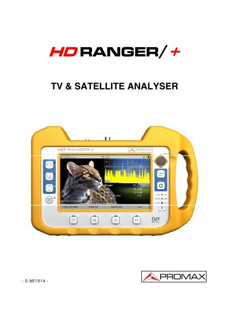
The new HD RANGER/+ is the fifth generation of field meters that PROMAX<br />
launches. As each new generation, it represents an evolution from the previous,<br />
since it integrates the latest technological innovations and develops applications<br />
for the new demands and needs that have emerged in recent years.<br />
The new HD RANGER/+ has been created with the aim to make easy the user<br />
experience. From its ergonomic design and stylized lines to the reduction of keys<br />
and the easy use of its interface, everything has been designed so the user has a<br />
simple tool to use but powerful and useful.<br />
Figure 1.<br />
The HD RANGER/+ is a universal field meter that covers TV standards of the<br />
DVB family, as well as formats such as MPEG-2 or MPEG-4 and Dolby audio.<br />
There is also the possibility of an extension to work in fibre optics installations.<br />
1 Trademark of the DVB - Digital Video Broadcasting Project.<br />
August 2012 1-1<br />
1
Besides the basic functions of TV meter and spectrum <strong>analyser</strong> for terrestrial and<br />
<strong>satellite</strong> band, it provides additional tools, such as the detection of 4G signal<br />
interferences (some of its working frequencies are close to the TV bands), the<br />
diagrams constellations or the echoes detection..<br />
The HD RANGER/+ has an application to manage data generated at each<br />
installation.This feature helps the user to manage information generated so he<br />
can access it at any time or download it to a PC for further analysis.<br />
The HD RANGER/+ has been designed and developed entirely in the European<br />
Union. A multidisciplinary team of highly qualified professionals has dedicated<br />
effort and commitment to the development of a powerful, efficient and reliable<br />
tool. During the manufacturing process, all used materials have been subjected<br />
to a strict quality control.<br />
In an effort to facilitate its work to professionals, our long experience ensures an<br />
after sales quality service, which includes updates and upgrades for free.<br />
Figure 2.<br />
1-2 August 2012
2 SETTING UP<br />
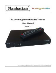
2.1 Package Content<br />
Check that your package contains the following elements:<br />
HD RANGER/+ Field Meter.<br />
External DC charger.<br />
Mains cord for external DC charger.<br />
Car lighter charger.<br />
"F" Adapters (3 units).<br />
• "F" / H - BNC / H Adapter.<br />
• "F" / H - DIN / H Adapter.<br />
• "F" / H - "F" / H Adapter.<br />
Support belt and carrying bag.<br />
USB On-the-go (A) Male - Mini USB (B) Male.<br />
USB cable (A) Male - Mini USB (B) Male.<br />
4V / RCA Jack Cable.<br />
Transport suitcase * .<br />
Quick Start Guide.<br />
NOTE: Keep the original packaging, since it is specially designed to protect the<br />
equipment. You may need it in the future to send the meter to be<br />
calibrated.<br />
* Supplied only with the HD RANGER + model. Optional Accessory on request for<br />
HD RANGER.<br />
August 2012 2-3
2.2 Power<br />
The HD RANGER/+ is powered by a 7.2 V built-in rechargeable Li-Ion battery<br />
of high quality and long duration.<br />
The equipment can operate on battery or connected to the network using a DC<br />
adapter. An adapter is also supplied to use with the power connector car<br />
(cigarette lighter).<br />
2.2.1 First charge<br />
The equipment comes with the battery fully charged. Depending on the time<br />
elapsed from first charge and environmental conditions may have lost some of<br />
the charge. Check the battery level.<br />
2.2.2 Charging the battery<br />
Connect the DC power adapter (2) to the equipment through the power<br />
connector on the left side panel (see figure 3).<br />
Figure 3.<br />
Then connect the DC power adapter to the mains via the mains cord (3).Ensure<br />
that your mains voltage is compatible with the adapter voltage.<br />
For a fast charging of the battery is necessary to switch off the equipment.<br />
If the equipment is ON, the battery charging will be slower, depending on the<br />
type of work you are doing. When connecting the equipment to the mains the<br />
mains connected symbol ( ) appears inside the battery icon.<br />
2-4 August 2012
When the computer is connected to the mains, the CHARGER indicator remains<br />
on. This indicator changes its colour according to the percentage of battery<br />
charge:<br />
RED Less than 80% of charge.<br />
ORANGE Between 80% and 90% of charge.<br />
GREEN 100% full charge.<br />
If the battery is weak, the battery disconnection circuit will prevent the<br />
equipment starting up. In this case, please charge the battery immediately.<br />
2.2.3 Charge / discharge times<br />
Average charging time with the equipment off (fast charge):<br />
3 hours to achieve an 80% charge.<br />
5 hours to achieve a 100% charge.<br />
With the equipment on (slow charge):<br />
5 hours to achieve an 80% charge.<br />
8 hours to achieve a 100% charge.<br />
Average discharge time (with external supply disabled):<br />
With the equipment full charge the average battery time is 5:30 hours.<br />
With the equipment at 80% charge the average battery time is 4 h.<br />
2.2.4 Smart control battery<br />
The built-in battery of the equipment is of the "smart" type, which means that<br />
reports its state of charge. This information is displayed inside the battery icon in<br />
the form of the average time available. In this way the user can know at any<br />
time the remaining battery level.<br />
The remaining time charge that appears is calculated according to the work that<br />
has been doing. If you activate the external supply of the equipment, the<br />
average time would be reduced according to the increase in consumption that<br />
occurs.<br />
August 2012 2-5
2.2.5 Usage Tips<br />
The battery is losing storage capacity as you go through its life. Contact your<br />
PROMAX distributor when necessary to replace the battery.<br />
To prolong battery life the user should follow these tips:<br />
Proceed to charge the battery preferentially when fully discharged.<br />
In case of providing a long inactivity period of the equipment is advisable<br />
to store it fully charged at temperatures below 25 ° C.<br />
It is advisable in these cases to make every 3 months a charge / discharge<br />
cycle and a subsequent partial charge (50%).<br />
2-6 August 2012
2.3 Equipment Details<br />
Front View<br />
Figure 4.<br />
August 2012 2-7
Lateral view<br />
Top view<br />
* Optical Option.<br />
Figure 5.<br />
Figure 6.<br />
2-8 August 2012
2.4 Switching On / Off the equipment<br />
This field meter is designed for use as a portable equipment and it does not<br />
require any previous installation.<br />
► Switching On:<br />
Slide up for a while the power slide switch located on the left side of the<br />
equipment (approximately one second).<br />
When all indicators light up at once release the switch, which returns to<br />
its rest position.<br />
The starting display picture appears and a progress bar that indicates the<br />
system load.<br />
After the system load the last screen before shutdown appears.<br />
► Switching Off:<br />
► Reset:<br />
Slide up for a while the power slide switch located on the left side of the<br />
equipment (approximately one second).<br />
When the screen goes off release the switch, which returns to its rest<br />
position.<br />
The starting display picture appears and the progress bar showing the<br />
system shutdown progress.<br />
Press the F4 key for 5 seconds. The equipment automatically turns off.<br />
Use only in case of system crash.<br />
In the PREFERENCES menu (press 1s), APPEARANCE tab, option "Off" you<br />
can activate the automatic shutdown option, selecting a waiting time (time<br />
without pressing any key) after which the meter turns off automatically.<br />
August 2012 2-9
2.5 Screen Icons and Dialog boxes<br />
At the top of the screen there is the status bar. On the right are icons that<br />
provide useful information to the user about the current status of the instrument.<br />
Battery charging.<br />
Battery not charging.<br />
Yellow level indicates<br />
percent charge left<br />
Battery not charging,<br />
time left indicator<br />
USB in serial port<br />
mode<br />
Satellite band.<br />
Terrestrial band.<br />
USB flash drive inserted<br />
LTE filter enabled.<br />
Current installation.<br />
Joystick multi-function<br />
Enabled Two-letter code<br />
indicates the exact function:<br />
FR Frequency tuning<br />
CH Channel tuning<br />
SP SPAN change<br />
MK Marker moving<br />
2-10 August 2012
2.6 Menu Tree<br />
SPECTRUM ANALYSER MENU<br />
TV MENU<br />
August 2012 2-11
MEASUREMENT MENU<br />
SETTINGS MENU<br />
2-12 August 2012
INSTALLATIONS MANAGEMENT / PREFERENCES MENU<br />
Figure 7.<br />
August 2012 2-13
2.7 Controls<br />
The equipment has been designed to be an easy tool to use. For this reason the<br />
number of keys has been reduced and these are grouped by function.<br />
For measurement and navigation through the menus, the equipment has a<br />
joystick, 4 programmable keys (softkeys) and 6 direct access keys.<br />
Next the use of each one of them is described:<br />
2.7.1 Joystick<br />
Joystick positions are:<br />
Figure 8.<br />
In the SPECTRUM ANALYSER mode, the joystick is multifunctional, that is,<br />
each time you press its function changes. The user can see the active function<br />
according to the icon that is displayed at the upper right of the equipment, as<br />
shown in the image. The functions are:<br />
CH: Channel tuning.<br />
FR: Frequency tuning.<br />
SP: SPAN change.<br />
MK: Marker moving.<br />
Figure 9.<br />
According to the selected function, the joystick will do a specific action.<br />
2-14 August 2012
2.7.2 Keyboard shortcuts<br />
► Function keys<br />
On the left side of the device are 3 keys to access the most important functions<br />
of the equipment.<br />
Measurement key.<br />
Spectrum <strong>analyser</strong> key.<br />
TV Mode Key.<br />
Pressing the key provides access to a different view within the same function.<br />
Each view is shown at the top. When reaching the third view it returns to the first<br />
view.<br />
August 2012 2-15
Measurements<br />
Figure 10.- FULL MEASUREMENT<br />
Figure 11.- MEASUREMENT + TV + SPECTRUM<br />
Figure 12.- MEASUREMENT + PARAMETERS<br />
2-16 August 2012
Spectrum Analyser<br />
Figure 13.- SPECTRUM + MEASUREMENT<br />
Figure 14.- SPECTRUM + MEASUREMENT + TV<br />
Figure 15.- FULL SPECTRUM<br />
August 2012 2-17
Modo TV<br />
Figure 16.- FULL TV<br />
Figure 17.- TV + SPECTRUM + MEASUREMENT<br />
Figure 18.- TV + SERVICE DATA<br />
2-18 August 2012
Screenshot key<br />
This key captures the screen currently being displayed and stores it in the<br />
memory of the equipment in PNG format. This screen can be displayed on the<br />
same instrument and if desired, downloaded to a computer.<br />
► Management Keys<br />
There are two Management keys:<br />
2.7.3 Softkeys<br />
Settings. It accesses the menus to configure the<br />
equipment.<br />
Installations Manager. It accesses the menus to<br />
check measurement data.<br />
There are four programmable keys, also called softkeys, numbered F1 to F4.<br />
Each key provides access to a menu. This menu varies depending on the function<br />
the user is working on the meter.<br />
The menu is displayed on each softkey at the bottom of the screen.<br />
Figure 19.<br />
August 2012 2-19
3 MEASUREMENT MODE<br />
3.1 Introduction<br />
At the left side, the equipment have three functions keys, which give direct<br />
access to the three most important functions. One of them is the key<br />
MEASURES ( ) that measures the signal received through the RF input<br />
connector.<br />
The user should connect a signal to the input and select the band, whether<br />
terrestrial or <strong>satellite</strong>. Then the auto stealth function locks the signal and<br />
demodulates it in real time, automatically detecting its characteristic parameters.<br />
Having identified the signal, the equipment measures according to the signal<br />
type. All information about transponders or multiplex is automatically displayed<br />
without introducing any additional parameter identification.<br />
Next there is a list of signals that the equipment can automatically detect and the<br />
characteristics of each one are described: identification parameters,<br />
measurements and recommended values.<br />
Digital Terrestrial Television First Generation (DVB-T)<br />
Digital Terrestrial Television Second Generation (DVB-T2 ∗ )<br />
Digital Satellite Television First Generation (DVB-S)<br />
Digital Satellite Television Second Generation (DVB-S2)<br />
Digital Cable Television First Generation (DVB-C)<br />
Digital Cable Television Second Generation (DVB-C2*)<br />
Analogue terrestrial TV<br />
Analogue Cable TV<br />
Analogue Satellite TV<br />
Analogue Terrestrial FM<br />
∗ Available only for HD RANGER +<br />
3-20 August 2012
3.2 Operation<br />
Connect the RF input signal to the equipment.<br />
Select through the Tune Settings menu the frequency band (terrestrial or<br />
<strong>satellite</strong>).<br />
Access the MEASURES option by pressing the key.<br />
Press again to display the next view.<br />
Views for the digital signal are:<br />
MEASUREMENT 1/3: FULL MEASUREMENT<br />
Figure 20.<br />
Selected installation, date and time.<br />
Number of view / total views.<br />
Selected band, battery level.<br />
Measurement value of the selected parameter.<br />
Graphical measurement of the selected parameter.<br />
Measurement values for the type of locked signal.<br />
Signal status (searching / locked/ multiplex name).<br />
Softkeys menus.<br />
► Joystick up / down: It changes selected parameter.<br />
August 2012 3-21
MEASUREMENT 2/3: MEASUREMENT + TV + SPECTRUM<br />
Figure 21.<br />
Selected installation, date and time.<br />
Image of the locked signal.<br />
Number of view / total views.<br />
Selected band, battery level.<br />
Spectrum of the locked signal.<br />
Measurement values for the type of locked signal.<br />
Signal status (searching / locked / multiplex name).<br />
Softkeys menus.<br />
► Joystick right / left: It changes the selected channel / frequency.<br />
3-22 August 2012
MEASUREMENT 3/3: MEASUREMENT + PARAMETERS<br />
Figure 22.<br />
Selected installation, date and time.<br />
Number of view / total views.<br />
Selected band, battery level.<br />
Demodulation parameters of the locked signal.<br />
Measurement values for the type of locked signal.<br />
Signal status (searching / locked / multiplex name).<br />
Softkeys menus.<br />
► Joystick right / left: It changes the selected channel / frequency.<br />
The following section describes in detail the measurements for each type of<br />
signal.<br />
August 2012 3-23
4 SPECTRUM ANALYSER MODE<br />
4.1 Introduction<br />
At the left side, the equipment has three function keys, which give direct access<br />
to the three most important functions. One of them is the SPECTRUM<br />
ANALYSER key that displays the signal spectrum received through the RF<br />
input connector.<br />
The Spectrum Analyser mode allows checking the signals on the frequency band,<br />
to visually identify any anomalies and to measure the signal and display the<br />
image tuned.<br />
4.2 Mode of operation<br />
Connect the RF input signal to the equipment.<br />
Select through the Tune Settings menu the frequency band (terrestrial<br />
or <strong>satellite</strong>).<br />
Access the MEASURES option by pressing the key.<br />
Press again to display the next view.<br />
4-24 August 2012
Views for the digital signal are:<br />
SPECTRUM 1/3: SPECTRUM + MEASUREMENTS<br />
Figure 23.<br />
Selected installation, date and time.<br />
Number of view / total views.<br />
Selected band, battery level.<br />
Measured values of the signal at the frequency / channel where is pointing<br />
the cursor.<br />
Spectrum in the band with the selected SPAN.<br />
Signal status (searching / locked / multiplex name).<br />
Softkeys menus.<br />
► Joystick up / down: It changes the reference level.<br />
► Joystick left / right: It changes SPAN / frequency or channel / marker<br />
position.<br />
August 2012 4-25
SPECTRUM 2/3: SPECTRUM + MEASUREMENT + TV<br />
Figure 24.<br />
Selected installation, date and time.<br />
Number of view / total views.<br />
Selected band, battery level.<br />
Measured values of the signal at the frequency / channel where is pointing<br />
the cursor.<br />
Image of the tuned signal.<br />
Spectrum in the band with the selected SPAN.<br />
Signal status (searching / locked / multiplex name).<br />
Softkeys menus.<br />
► Joystick up / down: It changes the reference level.<br />
► Joystick left / right: It changes SPAN / frequency or channel / marker<br />
position.<br />
4-26 August 2012
SPECTRUM 3/3: FULL SPECTRUM<br />
Figure 25.<br />
Selected installation, date and time.<br />
Number of view / total views.<br />
Selected band, battery level.<br />
Spectrum in the band with the selected SPAN.<br />
Softkeys menus.<br />
August 2012 4-27
4.3 Description of the FULL SPECTRUM screen.<br />
Horizontal reference line<br />
It indicates the signal level.<br />
Vertical axis<br />
It indicates the signal level.<br />
Vertical reference line<br />
It indicates the frequency.<br />
SPAN<br />
Figure 26.<br />
It is the frequency range displayed on the horizontal axis.<br />
The current SPAN value appears at the bottom right of the screen. To<br />
change use the joystick (left, right) in SPAN mode (SP) or change it by the<br />
"SPAN" Tuning menu (F1 key).<br />
SPAN values available are: Full (full band), 500 MHz, 200 MHz, 100 MHz,<br />
50 MHz, 32 MHz, 16 MHz and 8 MHz.<br />
Reference Level<br />
Power range is represented on the vertical axis.<br />
To change use the joystick (up, down; 10 dB steps).<br />
The equipment has an option to activate the automatic adjustment of the<br />
reference level, so it detects the optimal reference level for each situation.<br />
This option can be enabled or disabled through the PREFERENCES menu.<br />
4-28 August 2012
Cursor<br />
Red vertical line that indicates position during the channel or frequency<br />
tuning.<br />
To change use the joystick (left, right) in FR mode (tuning by frequency) or<br />
CH mode (tuning by channel).<br />
Marker<br />
It is a special cursor that can be placed on a given frequency to check the<br />
power in this point.<br />
To change use the joystick (left, right) in MARKER (MK) mode.<br />
This option can be enabled using the "MARKER" option from the Advanced<br />
menu (F4 key).<br />
4.4 JOYSTICK Operation in SPECTRUM ANALYSER mode.<br />
In the SPECTRUM ANALYSER mode, the joystick can make different actions<br />
depending on its active mode.<br />
The active mode of the joystick appears as an icon in the toolbar at the top right<br />
of the screen. Available modes are:<br />
► Frequency tuning.<br />
► Channel tuning.<br />
► SPAN change.<br />
► MARKER moving.<br />
To change the active mode press the joystick.<br />
Figure 27.<br />
Pressing left or right will take appropriate action according to the active mode.<br />
August 2012 4-29
Pressing up or down will change the reference level regardless the active mode.<br />
The frequency or channel tuning mode will appear depending on the selected<br />
tuning type. Access the ADJUST menu to select the type of tuning.<br />
To show the MARKER mode, it must be active.<br />
Access the ADVANCED menu (F4) to activate the MARKER.<br />
Pressing the joystick for 1 second, a box appears explaining the joystick modes<br />
available. From here user can also select the mode.<br />
4.5 Options Menu<br />
Figure 28.<br />
At the bottom of the screen four menus are accessible via the function keys.<br />
It displays the channel where is pointing the cursor<br />
and give access to the tuning menu.<br />
It displays the selected transmission standard and<br />
gives access to the signal parameters menu.<br />
It displays the Utilities menu.<br />
It displays the Advanced menu.<br />
Next each of these menus is described.<br />
4-30 August 2012
4.5.1 F1: Tuning<br />
Access by the function key , it contains the options to tune a channel.<br />
The tuning menu consists of the following options:<br />
► Channel / Frequency: It displays the channel / frequency pointed by the<br />
cursor.<br />
In channel tuning, it allows selecting a channel from the active channel<br />
plan:<br />
Place over the Channel option and press the JOYSTICK.<br />
A box appears with all channels of the active channel plan and its<br />
frequency.<br />
Move the JOYSTICK on the box to select a channel.<br />
When finished press JOYSTICK to save the selected value or any<br />
function key to exit without saving.<br />
The cursor will place on the selected channel and it will appear on the<br />
F1 option.<br />
In case of tuning by frequency, the frequency can be edited:<br />
Place over the Central Frequency option and press the JOYSTICK<br />
The option is highlighted in yellow to indicate it is in edit mode.<br />
Move the JOYSTICK left / right to move between the figures and up /<br />
down to change the figure.<br />
When finished press JOYSTICK to save the selected value or any<br />
function key to exit without saving.<br />
The Channel can be changed directly with the JOYSTICK in CH mode.<br />
August 2012 4-31
► Central Frequency: It displays the value of the central frequency on the<br />
screen. To edit:<br />
Place over the Frequency option and press the JOYSTICK.<br />
The option is highlighted in yellow to indicate it is in edit mode.<br />
Move the JOYSTICK left / right to move between the figures and up /<br />
down to change the figure.<br />
When finished press JOYSTICK to save the selected value or any<br />
function key to exit without saving.<br />
The frequency can be changed directly with the JOYSTICK in FR mode.<br />
► Level of reference: It displays the reference level. To edit:<br />
Place over the Reference Level option and press JOYSTICK.<br />
The option is highlighted in yellow to indicate it is in edit mode.<br />
Move the JOYSTICK left / right to move between the figures and up /<br />
down to change the figure.<br />
When finished press JOYSTICK to save the selected value or any<br />
function key to exit without saving.<br />
The Reference Level can be changed directly with the JOYSTICK up or<br />
down.<br />
► Span: It shows the SPAN, which is the frequency range displayed on<br />
screen. To edit:<br />
Place over the SPAN option and press the JOYSTICK.<br />
The option is highlighted in yellow to indicate it is in edit mode.<br />
Move the JOYSTICK left / right to move between the figures and up /<br />
down to change the figure.<br />
When finished press JOYSTICK to save the selected value or any<br />
function key to exit without saving.<br />
The SPAN can be changed directly with the JOYSTICK in SP mode.<br />
4-32 August 2012
4.5.2 F2: Signal Parameters<br />
Access by the function key, it allows selecting the standard transmission and<br />
displays the parameters for signal transmission.<br />
This menu allows selecting the transmission standard:<br />
► Type of signal: It displays the selected standard. It allows selecting another<br />
standard in the same band (terrestrial or <strong>satellite</strong>):<br />
4.5.3 F3: Tools<br />
Place over the Signal Type option and press the JOYSTICK.<br />
It displays a menu at the right with the transmission standards.<br />
Move the JOYSTICK up / down to select a standard.<br />
When finished press JOYSTICK to select the standard or any function<br />
key to exit without selecting.<br />
The remaining transmission parameters are detected through the locked<br />
signal.<br />
Access by the key. It access to the Tools menu. This menu can change<br />
depending on the type of selected standard. Tools are:<br />
► Constellation: It displays the constellation of the locked signal.<br />
► LTE Ingress Test: It enables the detection of signal interferences coming<br />
from mobile phones.<br />
► Echoes: It detects the echoes that may appear due to the simultaneous<br />
reception of the same signal from several transmitters.<br />
For more information about these features, see "Tools" chapter.<br />
August 2012 4-33
4.5.4 F4: Advanced<br />
Access by the function key, it allows selecting among several parameters to<br />
display the spectrum.<br />
The advanced menu consists of the following options:<br />
► Average: The user can select the amount of signal values to be used to<br />
set the average signal value to be displayed on screen. The<br />
larger the average value, the more stable the displayed signal<br />
appears.<br />
► Spectrum<br />
Line: It defines the spectrum display. Outline option displays the<br />
spectrum outline. The Solid option displays the contour of the<br />
spectrum with solid background.<br />
► Marker: It allows enabling / disabling the marker. This marker is<br />
displayed on screen with the shape of an arrowhead, showing<br />
on screen some information about the frequency and power<br />
level where it points. You can move left / right by the<br />
JOYSTICK in MK mode (press the JOYSTICK until the icon<br />
MK appears).<br />
► Max. Hold.: (Off / Permanent / Curtain). It allows the user to display the<br />
current signal with the maximum values measured for each<br />
frequency. The OFF option disables this function. The<br />
Curtain option displays the maximum values in blue for a<br />
moment with the current signal. The Permanent option<br />
maintains maximum signal on the screen. This option is<br />
especially useful for detecting sporadic noises.<br />
To select a parameter:<br />
Place over the option and press the JOYSTICK.<br />
The data field gets into the edit mode, indicated by the yellow<br />
background.<br />
A menu is displayed at the right with some options or if it is numeric, a<br />
number darkens.<br />
Move the JOYSTICK up / down to select one option. To move<br />
between figures press right / left and to change it press up / down.<br />
When finished press JOYSTICK or any function key to exit.<br />
4-34 August 2012
4.6 Location of a signal with the SPECTRUM ANALYZER<br />
Connect the cable with the input signal to the RF IN input connector.<br />
Press the SPECTRUM key. The spectrum of the signal is displayed.<br />
Adjust the SPAN (recommended value for a terrestrial signal 50 MHz<br />
and for a <strong>satellite</strong> signal 100 MHz). The current value of the SPAN is<br />
at the right bottom of the screen.<br />
Find the frequency of the signal by moving the JOYSTICK left or right<br />
to move sweeping the entire band.<br />
If you know the channel change the tuning by frequency to tuning by<br />
channel. The channel mode allows you to navigate from channel to<br />
channel, using the selected channel plan.<br />
When the channel is locked information appears at the bottom left of<br />
the screen.<br />
The equipment automatically detects transmission parameters of the<br />
signal and makes the corresponding measurements.<br />
August 2012 4-35
5 TV MODE<br />
5.1 Introduction<br />
On the left side of the front panel there are three functions, which give direct<br />
access to the three most important functions. One is the TV MODE key which<br />
displays the resulting image from the decoding the received RF signal.<br />
TV MODE demodulates the TV signal received by the RF input, so that the user<br />
can check the signal on the screen. It shows information about the channel and<br />
its services.<br />
5.2 Operation<br />
To access the TV MODE option, press the .<br />
The screen shows the tuned signal demodulated..<br />
For digital carriers, the first service of the terrestrial multiplex or<br />
<strong>satellite</strong> transponder appears. In case the signal is encoded the image<br />
will not appear.<br />
In the case of an analogue signal, tuned signal will appear.<br />
To access the next view (if digital signal) of the TV MODE, press the<br />
again. At the end view it will return back to the first.<br />
5-36 August 2012
Views for the digital signal are:<br />
TV 1/3: FULL TV<br />
Figure 29.<br />
Selected installation, date and time.<br />
Number of view / total views.<br />
Selected band, battery level.<br />
Tuned service image.<br />
Signal status (searching / locked / multiplex name).<br />
Softkeys menus.<br />
► Joystick up / down: It changes service.<br />
► Joystick left / right: It changes channel / frequency.<br />
August 2012 5-37
TV 2/3: TV + SPECTRUM + MEASUREMENT<br />
Figure 30.<br />
Selected installation, date and time.<br />
Number of view / total views.<br />
Selected band, battery level.<br />
Tuned service image.<br />
Spectrum.<br />
Measured values of the signal in the frequency / channel the cursor is<br />
pointing.<br />
Signal status (searching / locked / multiplex name).<br />
Softkeys menus.<br />
► Joystick up / down: It changes service.<br />
► Joystick left / right: It changes channel / frequency.<br />
5-38 August 2012
TV 3/3: SCREEN TV + SERVICE DATA<br />
Figure 31.<br />
Selected installation, date and time.<br />
Tuned service image.<br />
Tuned service information.<br />
► TYPE: Encoding type and video transmission rate.<br />
► FORMAT: Resolution (horizontal x vertical) aspect ratio and<br />
frequency.<br />
► PROFILE: Profile level.<br />
► PID: Video program identifier.<br />
► 3D: Application of 3D technology.<br />
Number of view / total views.<br />
Selected band, battery level.<br />
Tuned service information.<br />
► NETWORK: Television distribution network (Terrestrial). Orbital<br />
position (Satellite).<br />
► PROVIDER: Provider name of the program.<br />
► NID: Network identifier where the signal is distributed.<br />
► ONID: Identifier of the original network where the signal<br />
originates.<br />
► TSID: Transport stream identifier.<br />
► SID: Service Identifier.<br />
► MHP: Interactive service.<br />
► FREE /<br />
SCRAMBLED: Free / scrambled emission.<br />
► DTV/DS/<br />
ANALOG: Standard type of transmission.<br />
August 2012 5-39
Tuned audio information.<br />
► TYPE: Type of audio encoding and transmission speed<br />
► FORMAT:<br />
► LANGUAGE: Broadcasting language.<br />
► PID: ID of the audio program.<br />
Softkeys menus.<br />
► Joystick up / down: It changes service.<br />
► Joystick left / right: It changes channel / frequency.<br />
5.3 Menu Options<br />
5.3.1 ANALOGUE signal<br />
Number of channel / frequency tuned.<br />
Parameters of the tuned signal.<br />
5.3.2 Terrestrial / Satellite Digital Signal<br />
5.3.2.1 F1: Number of Channel / Frequency tuned.<br />
It displays the channel.<br />
It allows editing frequency or change channel in the active channel plan.<br />
5.3.2.2 F2: Standard of the tuned signal.<br />
It shows the parameters of the tuned signal.<br />
It displays the menu to select the standard of the channel plan.<br />
5-40 August 2012
5.3.2.3 F3: Selected service name.<br />
It displays the list of services available in the multiplex tuned, with information<br />
about the service type and the identification number.<br />
Icons that appear next to the service name identify the features of the service.<br />
The meaning is given in the following table:<br />
Digital TV<br />
service<br />
Digital radio Data<br />
Scrambled<br />
service<br />
5.3.2.4 F4: Language of the selected service.<br />
High Definition<br />
TV service<br />
It gives access to the list of available audio tracks in the selected service.<br />
August 2012 5-41
6 TOOLS<br />
6.1 Constellation<br />
6.1.1 Description<br />
The constellation diagram is a graphic representation of the digital symbols<br />
received over a period of time. There are different types of constellation<br />
diagrams according to the modulation type.<br />
In the case of an ideal transmission channel without noise or interference, all<br />
symbols are recognized by the demodulator without errors. In this case, they<br />
are represented in the constellation diagram as well defined points hitting in<br />
the same area forming a very concentrated dot.<br />
Noise and interferences cause the demodulator to not always read the symbols<br />
correctly. In this case hits are dispersed and create different forms which can<br />
visually determine the type of problem in the signal.<br />
Each type of modulation is represented differently. A 16-QAM signal is shown<br />
on screen by a diagram of a total of 16 different zones and a 64-QAM signal is<br />
represented by a diagram of 64 different zones and so on.<br />
The constellation diagram shows in different colours the density of hits and<br />
includes features to zoom, move and delete the display on screen.<br />
6.1.2 Operation<br />
The constellation is available to all DIGITAL signals, both terrestrial and<br />
SATELLITE.<br />
To access the utility CONSTELLATION:<br />
Connect the RF input signal to the equipment.<br />
Tune to a digital signal from <strong>satellite</strong> or terrestrial band.<br />
Enter the mode MEASURES and SPECTRUM mode .<br />
Press the F3 key (Utilities).<br />
Select CONSTELLATION.<br />
CONSTELLATION appears the tuned signal.<br />
6-42 August 2012
The following describes the constellation screen:<br />
Figure 32.<br />
Selected installation, date and time.<br />
Constellation window.<br />
The colour scale placed at the left side indicates the signal quality in a<br />
qualitative way by a gradation of colours proportional to the density of<br />
symbols concentrated in a given area. The colour scale ranges from black<br />
(no symbols) to red (highest density).<br />
Greater dispersion of the symbols indicates higher noise level or worse<br />
signal quality signal. If there is symbols concentration, this is indicative of<br />
good ratio signal / noise or absence of problems.<br />
Banda selected, battery level.<br />
Constellation modulation.<br />
Data Window.<br />
The data shown are first Carrier; end Carrier, Power, C / N and frequency.<br />
Spectrum of the tuned signal.<br />
Spectrum is displayed with the SPAN selected at the SPECTRUM mode.<br />
Signal status (searching / locked / multiplex name).<br />
Softkeys menus.<br />
Joystick Left / Right: SPAN Change<br />
August 2012 6-43
6.1.3 Menu Options<br />
At the bottom of the screen there are four menus accessible via the function<br />
keys.<br />
It displays the channel / frequency where is pointing<br />
the cursor and access the tuning menu.<br />
It displays the selected transmission standard menu<br />
and accesses the signal parameters.<br />
It displays the Tools menu.<br />
It displays the Advanced menu.<br />
In the Advanced menu there are options for the configuration of the<br />
constellation. They are:<br />
► Grid type:<br />
Full Grid: The grid where the constellation is displayed is a complete<br />
grid.<br />
Cross Grid: The grid where the constellation is displayed is made of<br />
crosses.<br />
► Start Carrier / Stop Carrier:<br />
The transmission of any digital channel consists of about 8,000 carriers, of<br />
which 6,817 are useful. These are divided in signalling carriers and data<br />
carriers. This option allows selecting the range of carriers to be displayed<br />
between the first and last.<br />
6.2 LTE Ingress test<br />
6.2.1 Description<br />
Long Term Evolution is a new standard for mobile networks. This mobile<br />
communication standard uses a frequency band close to the bands used by<br />
television. For this reason it can cause interferences.<br />
The LTE Ingress Test identifies this type of interferences in a television<br />
distribution system, so that they can be compared on the same screen the<br />
reception with LTE filter and without LTE filter and thus if there is any<br />
interference it can be detected and take appropriate action to fix it.<br />
6-44 August 2012
6.2.2 Operation<br />
The LTE Ingress Test input is available to all DIGITAL TERRESTRIAL<br />
signals.<br />
To access the LTE Ingress Test tool:<br />
Connect the RF input signal to the equipment.<br />
Tune a digital signal of the terrestrial band.<br />
Enter the MEASUREMENT mode or SPECTRUM mode .<br />
Press the F3 key (Utilities).<br />
Select the LTE Ingress Test mode.<br />
Enable / disable the LTE filter.<br />
This function displays on the same screen measurements obtained with the<br />
LTE filter or without LTE filter. Measuring the signal with filter or without filter<br />
is not done simultaneously, but alternately, by means of the F4 key that<br />
activates or deactivates the filter.<br />
The following describes the LTE display:<br />
Figure 33.<br />
Selected installation, date and time.<br />
Elapsed time with filter ON.<br />
Measurement with filter ON: MER (minimum, maximum) and power<br />
(minimum, maximum).<br />
August 2012 6-45
Signal with LTE filter ON.<br />
Identifier icon of the LTE filter ON.<br />
Selected band, battery level.<br />
Elapsed Time with filter OFF.<br />
Measurement with filter OFF: MER (minimum, maximum) and power<br />
(minimum, maximum).<br />
Signal with LTE filter OFF.<br />
Measurement units / centre frequency / Span.<br />
Signal status (searching / locked / multiplex name).<br />
Softkeys menus.<br />
6.2.3 Options Menu<br />
At the bottom of the screen are four menus accessible via the function keys.<br />
It displays channel / frequency and access the tuning<br />
menu.<br />
It displays the selected transmission standard menu<br />
and accesses the signal parameters.<br />
It displays the Tools menu.<br />
It enables / disables the filter LTE.<br />
6-46 August 2012
6.3 Echoes<br />
6.3.1 Description<br />
The Echoes option shows the response in time of a digital terrestrial channel<br />
and therefore it can detect echoes that can occur due to the simultaneous<br />
reception of the same signal from several transmitters with different delays<br />
and amplitudes.<br />
Another cause that may cause echoes is reflection of the signal on large<br />
objects, as buildings or mountains. This may be the explanation that having a<br />
good C / N and a good signal, the BER does not reach the minimum value.<br />
With the Echo function is possible to know the distance from where the<br />
equipment is to the transmitter or the object that caused the echo. Thus, the<br />
installer can minimise the effect that the echo may cause on the installation,<br />
reorienting the antenna and reducing the effect of received echoes.<br />
This function is only available for DVB-T and DVB-T2. Therefore, previously<br />
have to configure the apparatus for the reception of such signals.<br />
6.3.2 Operation<br />
Echoes function is available to DVB-T and DVB-T2 signals.<br />
Connect the RF input signal to the equipment.<br />
Tune a DVB-T or DVB-T2 digital signal at the terrestrial band.<br />
Enter the MEASUREMENTS mode and SPECTRUM mode .<br />
Press the F3 key (Utilities).<br />
Select ECHOES.<br />
The ECHOES function of the tuned signal appears on screen.<br />
August 2012 6-47
The following describes the ECHOES screen:<br />
Figure 34.<br />
Selected installation, date and time.<br />
Selected band, battery level.<br />
Main signal data: Frequency, Power and C / N.<br />
ECHOES Diagram.<br />
The display shows a graphical representation of the echoes. The<br />
horizontal axis of the graph corresponds to the delay in receiving the<br />
echo on the main path (the stronger signal).The vertical axis represents<br />
the attenuation of the echo in dB on the main path.<br />
The area next to the main signal is in a different colour. This area<br />
represents the guard interval. If the echo is found outside this area may<br />
affect the transmission.<br />
Data box with main data regarding echoes.<br />
In the list of echoes it shows the power, the delay in microseconds and<br />
the distance in kilometres to the echoes.<br />
Signal status (searching / locked / multiplex name).<br />
Softkeys menus.<br />
► Joystick left / right (CHANNEL mode): It changes the channel.<br />
► Joystick left / right (ECHOES mode): It moves cursor over the echoes<br />
window.<br />
► Joystick up / down (ECHOES mode): It changes Zoom.<br />
Remember to press the joystick to change the ECHOES mode to CHANNEL<br />
mode.<br />
6-48 August 2012
6.3.3 Menu Options<br />
At the bottom of the screen there are four menus available via the function keys.<br />
It displays the channel / frequency where is pointing<br />
the cursor and access the tuning menu.<br />
It displays the selected transmission standard menu<br />
and accesses the signal parameters.<br />
It displays the Tools menu.<br />
6.4 Installations Management<br />
It displays the Advanced menu. The ZOOM option<br />
changes the zoom on the echoes windows. Zooms<br />
are 1x, 2x, 4x and 8x.<br />
The Installations Management is a program embedded in the equipment that<br />
allows the user to easily create a file (installation) to individually store and<br />
manage data for each installation. Installation measurements are stored in its<br />
corresponding folder. These measures can then be displayed and downloaded to<br />
a PC.<br />
If the user does not create any file installation, the equipment stores<br />
measurements in the installation file that is preinstalled by default.<br />
To access the Installations menu press the key.<br />
The advanced menu consists of the following options:<br />
Installation<br />
Manager: It opens a wizard to create a new installation file.<br />
Change to: It displays a menu with all the installations files created and<br />
allows the user to select the installation to save<br />
measurements. Installation selected appears at the upper left<br />
corner of the screen, next to the time, accompanied by the<br />
symbol .<br />
Edit<br />
installation: It opens a window showing all data of the selected installation<br />
and allows editing it (more details in the next section).<br />
Channel Set: It displays a menu with all associated channels set to the<br />
selected installation. The user has to select the one is going<br />
to work with.<br />
August 2012 6-49
6.5 Installation Manager<br />
When accessing the INSTALLATION MANAGER the following screen appears:<br />
Figure 35.<br />
The window is divided into three fields:<br />
Installation data<br />
It displays information about the installation using the following<br />
fields:<br />
► Name:<br />
Name of the installation file.<br />
► Created:<br />
Date the installation file creation.<br />
► File:<br />
Number of files which make the installation and current size.<br />
► TER Channel Sets:<br />
It shows the number of channel sets used in the installation.<br />
► SAT Channel Sets<br />
It displays the number of channel sets used in the installation.<br />
► Free Space<br />
It displays the amount of memory available for the selected<br />
installation.<br />
6-50 August 2012
List of channel sets and screenshots<br />
It shows all channel sets and / or screenshots available for the selected<br />
installation.<br />
Display area<br />
It is the area where the selected file is displayed, both channel set and<br />
screenshots.<br />
In the case of displaying a channel set file, it shows the name, the band<br />
and the number of channels of the channel set on which the cursor is<br />
placed.<br />
For a screenshot, it shows the full screen, as captured. Screenshots are<br />
saved with PNG extension.<br />
At the bottom there are four function keys. Each one displays a menu. They are<br />
described below.<br />
VIEW<br />
► All:<br />
It displays all available channel sets and screenshots.<br />
► Screenshots:<br />
It shows all available screenshots.<br />
► Channel Sets:<br />
It shows all available channel sets.<br />
FILE<br />
► Mark All:<br />
It marks all files in the list of channel sets screenshots.<br />
► Unmark All:<br />
It deselect all files in the list of channel sets and screenshots.<br />
► Rename:<br />
It renames a selected file.<br />
► Delete:<br />
It deletes all selected files.<br />
► Copy to USB:<br />
It saves selected files on a USB stick connected to the<br />
instrument.<br />
August 2012 6-51
INSTALLATION<br />
► Edit name:<br />
It edits the name of the currently selected installation.<br />
► Delete:<br />
It deletes the name of the currently selected installation.<br />
► Duplicates:<br />
It allows double the currently selected installation.<br />
CURRENT INSTALLATION<br />
The function key displays the name of the current installation.<br />
Pressing the key, a menu displays installations available so the<br />
user can switch installation.<br />
6-52 August 2012
7 SPECIFICATIONS<br />
7.1 Specifications HD RANGER+<br />
CONFIGURATION FOR MEASURING LEVEL AND POWER<br />
TUNING Digital frequency synthesis. Continuous tuning from 5 to 1000 MHz<br />
MEASURE and from 950 to 2150 MHz. (Terrestrial and Satellite respectively).<br />
Tuning<br />
Demodulator<br />
Digital frequency synthesis.<br />
Terrestrial TV<br />
& FM bands<br />
45 - 860 MHz.<br />
Terrestrial<br />
tunable range<br />
5 - 1000 MHz.<br />
Satellite TV<br />
band<br />
950 - 2150 MHz.<br />
Tuning modes Channel or frequency (IF or downlink at <strong>satellite</strong> band). Channel<br />
plan configurable on demand.<br />
Resolution<br />
RF INPUT<br />
10 kHz.<br />
Impedance 75 Ω.<br />
Maximum<br />
signal<br />
130 dBµV.<br />
Maximum input voltage<br />
DC to 100 Hz 50 V rms (powered by the AL-103 power charger).<br />
30 V rms (not powered by the AL-103 power charger).<br />
5 MHz to<br />
2150 MHz<br />
140 dBµV. (protected at least for 30 seconds).<br />
DIGITAL SIGNALS MEASUREMENT<br />
MARGIN OF POWER MEASUREMENT<br />
COFDM: 35 dBµV to 115 dBµV.<br />
QAM: 35 dBµV to 115 dBµV.<br />
QPSK/8PSK: 35 dBµV to 115 dBµV.<br />
MEASUREMENTS<br />
DVB-T<br />
(COFDM)<br />
Power, CBER, VBER, MER (up to 35 dB), C/N and Link margin.<br />
Presentation: Numeric and level bar.<br />
DVB-T2 Power, CBER, MER (up to 35 dB), C/N, LBER, BCH ESR, LDPC<br />
(COFDM): Iterations and Wrong Packets.<br />
Presentation: Numeric and level bar.<br />
DVB-C (QAM): Power, BER, MER (up to 35 dB), C/N and Link margin.<br />
Presentation: Numeric and level bar.<br />
DVB-C2 Power, CBER, MER (up to 35 dB), C/N, LBER, BCH ESR, LDPC<br />
(COFDM): Iterations and Wrong Packets.<br />
Presentation: Numeric and level bar.<br />
DVB-S (QPSK): Power, CBER, VBER, MER (up to 30 dB), C/N and Link margin.<br />
Presentation: Numeric and level bar.<br />
August 2012 7-53
DVB-S2 Power, CBER, LBER, MER (up to 30 dB), C/N, BCH ESR, Wrong Packets<br />
(QPSK/8PSK): and Link Margin.<br />
Presentación: Numeric and level bar.<br />
DVB-T SIGNAL PARAMETERS<br />
Carriers 2k / 8k.<br />
Guard Interval 1/4, 1/8, 1/16, 1/32.<br />
Code Rate 1/2, 2/3, 3/4, 5/6, 7/8.<br />
Modulation QPSK, 16-QAM, 64-QAM.<br />
Bandwidth 6, 7 and 8 MHz.<br />
Spectral<br />
inversion<br />
ON, OFF (AUTO).<br />
Hierarchy Indicates hierarchy mode.<br />
Cell ID Detected from transmitter station.<br />
TPS signalling Time slicing, symbol interleave and MPE-FEC.<br />
DVB-T2 SIGNAL PARAMETERS<br />
Carriers 1k, 2k, 4k, 8k, 8k+ EXT, 16k, 16k+ EXT, 32k, 32k+ EXT.<br />
Guard Interval 1/4, 19/256, 1/8, 19/128, 1/16, 1/32, 1/128.<br />
Bandwidth 5, 6, 7 and 8 MHz.<br />
Spectral<br />
Inversion<br />
ON, OFF (AUTO).<br />
Pilot Pattern PP1-PP8.<br />
Code Rate PLP 1/2, 3/5, 2/3, 3/4, 4/5, 5/6.<br />
PLP<br />
Constellation<br />
QPSK, 16QAM, 64QAM, 256QAM.<br />
PLP<br />
Constellation<br />
Rotation<br />
ON / OFF (AUTO).<br />
PLP ID 0-256.<br />
ID CELL Detected from transmitter station.<br />
Network ID Detected from transmitter station.<br />
T2 System ID Detected from transmitter station.<br />
DVB-C SIGNAL PARAMETERS<br />
Demodulation 16/32/64/128/256 QAM.<br />
Symbol rate 1800 to 7200 kbauds.<br />
Roll-off (α)<br />
factor of<br />
Nyquist filter<br />
0.15.<br />
Spectral<br />
inversion<br />
ON, OFF (AUTO).<br />
7-54 August 2012
DVB-C2 SIGNAL PARAMETERS<br />
Carriers 4k.<br />
Guard Interval 1/64, 1/128.<br />
Bandwidth 6 and 8 MHz.<br />
Spectral ON, OFF (AUTO).<br />
Inversion<br />
Code Rate PLP 2/3, 3/4, 4/5, 5/6, 8/9, 9/10.<br />
PLP<br />
64QAM, 256QAM, 1kQAM and 4kQAM.<br />
Constellation<br />
Dslice ID 0-256.<br />
PLP ID 0-256.<br />
ID cell Detected from transmitter station.<br />
Network ID Detected from transmitter station.<br />
C2 System ID Detected from transmitter station.<br />
DVB-S SIGNAL PARAMETERS<br />
Symbol rate 2 to 45 Mbauds.<br />
Roll-off (α) 0.35.<br />
factor of<br />
Nyquist filter<br />
Code Rate 1/2, 2/3, 3/4, 5/6, 7/8.<br />
Spectral ON, OFF (AUTO).<br />
inversion<br />
DVB-S2 SIGNAL PARAMETERS<br />
Symbol rate 2 to 45 MSps.<br />
(QPSK)<br />
Symbol rate 2 to 45 MSps.<br />
(8PSK)<br />
Roll-off (α) 0.20, 0.25 and 0.35.<br />
factor of<br />
Nyquist filter<br />
Code Rate 1/2, 3/5, 2/3, 3/4, 4/5, 5/6, 8/9, 9/10.<br />
(QPSK)<br />
Code Rate 3/5, 2/3, 3/4, 5/6, 8/9, 9/10.<br />
(8PSK)<br />
Spectral ON, OFF (AUTO).<br />
inversion<br />
Pilots Presence indication.<br />
TOOLS<br />
CONSTELLATION DIAGRAM<br />
Type of signal DVB-T, DVB-T2, DVB-C, DVB-C2, DVB-S and DVB-S2.<br />
Presentation I-Q graph.<br />
August 2012 7-55
ECHOES ANALYSER MODE (DVB-T / DVB-T2 / DVB-C2)<br />
Measurement Depends on the standard, carrier and guard interval.<br />
range<br />
Delay 0.1 ms to 224 ms. Typical configuration (DVB-T 8K, GI = 1/4)<br />
Distance 0.3 km to 67.2 km. Typical configuration (DVB-T 8K, GI = 1/4)<br />
Power range 0 dBc to –30 dBc. Typical configuration (DVB-T 8K, GI = 1/4)<br />
Time scale 1/3 symbol period<br />
DATALOGGER function 2<br />
(Automatic measurement acquisition and storage)<br />
Stored data Signal type, modulation parameters, all measures available for<br />
the detected signal type, and time stamp.<br />
Timestamp Date and time at each measured channel.<br />
LTE INGRESS<br />
Type of signal DVB-T, DVB-T2, DVB-C, DVB-C2, DVB-S and DVB-S2.<br />
Presentation LTE band plus quality parameters for a selected TV channel.<br />
SAT IF TEST Function 3<br />
(IF distribution network response for <strong>satellite</strong> band.)<br />
Test<br />
3 selectable pilots.<br />
frequencies<br />
ATTENUATION TEST Function 4<br />
(Function to be used with RP-250 or RP-080 multiple pilot generator).<br />
Test<br />
3 selectable pilots.<br />
frequencies<br />
VIDEO & AUDIO<br />
Format MPEG-2 (MP@HL) (Main Profile High Level). MPEG-4 AVC H.264.<br />
Aspect Ratio 16 / 9 or 4 / 3.<br />
SI/PSI data Service list and main PIDs.<br />
HD Video 1080, 720 and 576, progressive or interlaced.<br />
Resolution<br />
Audio MPEG-1, MPEG-2, HE-AAC, Dolby Digital and Dolby Digital Plus.<br />
ANALOGUE SIGNALS MEASUREMENT<br />
LEVEL MEASUREMENT<br />
Measurement range<br />
Terrestrial TV 15 dBµV to 130 dBµV (3,16 µV to 3,16 V).<br />
& FM bands<br />
Satellite TV 20 dBµV to 130 dBµV (31,6 µV to 3,16 V).<br />
band<br />
2 Using NetUpdate4 software application with a Windows PC platform.<br />
3 Function to be used with RP-250 or RP-050 IF multiple pilot generator.<br />
4 Function to be used with RP-250 or RP-080 multiple pilot generator.<br />
7-56 August 2012
Attenuation Auto-range.<br />
scale<br />
Numerical Absolute value according to selected units.<br />
indication<br />
Graphical Analogue bar on screen.<br />
indication<br />
Measurement 100 kHz.<br />
bandwidth<br />
Audible Pitch sound. A tone with pitch proportional to signal strength.<br />
indicator<br />
Accuracy<br />
Terrestrial ±1,5 dB (25-120 dBµV, 45-1000 MHz) (22 °C ± 5 °C).<br />
bands<br />
Satellite band ±1,5 dB (35-100 dBµV, 950-2050 MHz) (22 °C ± 5 °C).<br />
Out of range .<br />
indication<br />
RF MEASUREMENTS<br />
Terrestrial bands<br />
Analogue Level, Video-Audio ratio, Carrier-Noise ratio.<br />
channels<br />
Digital<br />
Channel power, Carrier-Noise ratio.<br />
channels<br />
Satellite band<br />
Analogue Level and Carrier-Noise ratio.<br />
channels<br />
Digital<br />
Channel power and Carrier-Noise ratio.<br />
channels<br />
SPECTRUM ANALYSER MODE<br />
Measurement range<br />
Satellite band 10 dBµV to 130 dBµV (3.16 µV to 3.16 V).<br />
Terrestrial 10 dBµV to 130 dBµV (3.16 µV to 3.16 V).<br />
bands<br />
Measurement bandwidth<br />
Terrestrial 100 kHz.<br />
Satellite 100 kHz.<br />
Span<br />
Terrestrial Full span (full band) - 500 - 200 - 100 - 50 - 20 - 10 MHz<br />
selectable.<br />
Satellite Full span (full band) - 500 - 200 - 100 - 50 - 20 - 10 MHz<br />
selectable.<br />
Markers 1 with frequency and level indication.<br />
Reference 65 dBµV to 135 dBµV, adjustable in steps of 5 dB.<br />
level<br />
August 2012 7-57
Measurements<br />
Terrestrial bands<br />
Analogue Level, C/N, V/A.<br />
channels<br />
Digital<br />
Channel power, C/N, MER and BER (according to modulation<br />
channels type).<br />
Satellite band<br />
Analogue Level, C/N.<br />
channels<br />
Digital<br />
Channel power, C/N, MER and BER (according to modulation<br />
channels type).<br />
Spectrum Span, dynamic range and reference level are variable by means<br />
range<br />
of arrow cursors.<br />
ANALOG TV MONITOR DISPLAY<br />
Monitor 7 inches TFT. Transmissive colour dot matrix type.<br />
Aspect ratio 16:9.<br />
Dot format 800 × (R,G,B) (W) × 480(H).<br />
Brightness 700 cd/m2.<br />
TV STANDARD<br />
Colour system PAL, SECAM and NTSC.<br />
Analogue TV M, N, B, G, I, D, K and L.<br />
standard<br />
supported<br />
Analogue TV 40 dBµV for a correct synchronism.<br />
sensibility<br />
BASE BAND SIGNAL<br />
VIDEO<br />
Codecs Video DVB: MPEG-2 (MP@HL) (Main Profile High Level). MPEG-4 AVC H.264<br />
(High Profile Level 4.1).<br />
V/A input Multipole jack (75 Ω).<br />
Sensibility 1 Vpp (75 Ω) positive video.<br />
V/A output Multipole jack (75 Ω).<br />
SOUND<br />
Input Same V/A multipole jack (75 Ω).<br />
Outputs Built in speaker, same multipole jack.<br />
Codecs Audio MPEG-1, MPEG-2, HE-AAC, Dolby Digital and Dolby Digital Plus.<br />
Demodulation According to the TV standard.<br />
Analogue TV 50 µs, 75 µs (NTSC).<br />
de-emphasis<br />
Sound<br />
Digital frequency synthesis according to the TV standard.<br />
subcarrier<br />
USB<br />
“USB On-the-go” for remote control and file transfer.<br />
INTERFACE Mass Storage Host: The equipment can read / write on Flash<br />
drives.<br />
USB CDC: (Communications Device Class).<br />
7-58 August 2012
EXTERNAL UNIT POWER<br />
SUPPLY (Through the RF input connector).<br />
Terrestre External or 5/12/ and 24 V.<br />
Satélite External 13/15/18 V (up to 500mA).<br />
22 kHz signal (Selectable in <strong>satellite</strong> band)<br />
Voltage 0,65 V ± 0,25 V.<br />
Frequency 22 kHz ± 4 kHz.<br />
Maximum At least 6 W for 13/15/18/24 V and 2.5 W for 5 V.<br />
power 5<br />
DiSEqC<br />
GENERATOR 6<br />
According to DiSEqC 1.2 standard.<br />
POWER SUPPLY<br />
Internal 7.2 V 13 Ah Li-Ion intelligent battery.<br />
Batteries<br />
Autonomy > 5 hours in continuous mode (no EXT supply active).<br />
Recharging 3 hours up to 80% (instrument off).<br />
time<br />
External 12 V DC (using only PROMAX supplied accessories).<br />
Voltage<br />
Consumption 35 W.<br />
Auto power off Programmable. After the selected amount of minutes without<br />
operating on any control. Deactivable.<br />
OPERATING ENVIRONMENTAL CONDITIONS<br />
Altitude Up to 2000 m.<br />
Temperature From 5 to 45 °C (Automatic disconnection by excess of<br />
range<br />
temperature).<br />
Max. relative 80 % (up to 31°C),decreasing lineally up to 50% at 40 °C.<br />
humidity<br />
MECHANICAL FEATURES<br />
Dimensions 290 (W) x 185 (H) x 65 (D) mm.<br />
Weight 1.9 kg.(Total size: 3.487 cm3).<br />
5 If you select 5V, the maximum power shall not exceed 2.25 W (450 mA).<br />
6 DiSEqC TM is a trademark of EUTELSAT.<br />
August 2012 7-59
INCLUDED ACCESSORIES.<br />
1x CC-046 CABLE JACK 4V/RCA.<br />
1x CC-041 Connection USB Cable On-the-go (A) Male – Mini USB (B) Male.<br />
1x CC-045 USB Cable (A) Female – Mini USB (A) Male.<br />
1x AA-103 Car lighter charger.<br />
1x AL-103 External DC charger.<br />
1x AD-055 "F"/H-BNC / H adapter.<br />
1x AD-056 "F"/H-"DIN"/H adapter.<br />
1x AD-057 "F"/H-"F"/H adapter.<br />
1x CA-005 Mains cord.<br />
1x CB-083 Batería recargable Li+ 7,2 V 13 Ah.<br />
1x DC-300 Transport belt and small accessory bag.<br />
1x DC-230 Transport suitcase.<br />
RECOMMENDATIONS ABOUT THE PACKING<br />
It is recommended to keep all the packing material in order to return the<br />
equipment, if necessary, to the Technical Service.<br />
7-60 August 2012
7.2 Specifications HD RANGER<br />
CONFIGURATION FOR MEASURING LEVEL AND POWER<br />
TUNING<br />
MEASURE<br />
Digital frequency synthesis. Continuous tuning from 5 to<br />
1000 MHz and from 950 to 2150 MHz. (Terrestrial and Satellite<br />
respectively).<br />
Digital frequency synthesis.<br />
Tuning<br />
Demodulator<br />
Terrestrial TV 45 - 860 MHz.<br />
& FM bands<br />
Terrestrial 5 - 1000 MHz.<br />
tuneable<br />
range<br />
Satellite TV 950 - 2150 MHz.<br />
band<br />
Tuning modes Channel or frequency (IF or downlink at <strong>satellite</strong> band). Channel<br />
plan configurable on demand.<br />
Resolution 10 kHz.<br />
RF INPUT<br />
Impedance 75 Ω.<br />
Maximum 130 dBµV.<br />
signal<br />
Maximum input voltage<br />
DC to 100 Hz 50 V rms (powered by the AL-103 power charger).<br />
30 V rms (not powered by the AL-103 power charger).<br />
5 MHz to 140 dBµV. (protected at least for 30 seconds).<br />
2150 MHz<br />
DIGITAL SIGNALS MEASUREMENT<br />
MARGIN OF POWER MEASUREMENT<br />
COFDM: 35 dBµV to 100 dBµV.<br />
QAM: 45 dBµV to 110 dBµV.<br />
QPSK/8PSK: 44 dBµV to 114 dBµV.<br />
MEASUREMENTS<br />
DVB-T<br />
Power, CBER, VBER, MER.<br />
(COFDM)<br />
Presentation: Numeric and level bar.<br />
DVB-C (QAM): Power, BER, MER, C/N and Link margin.<br />
Presentation: Numeric and level bar.<br />
DVB-S (QPSK): Power, CBER, VBER, MER (up to 30 dB), C/N and Link margin.<br />
Presentation: Numeric and level bar.<br />
DVB-S2 Power, CBER, LBER, MER (up to 30 dB), C/N, BCH ESR, Wrong Packets<br />
(QPSK/8PSK): and Link Margin.<br />
Presentation: Numeric and level bar.<br />
August 2012 7-61
DVB-T SIGNAL PARAMETERS<br />
Carriers 2k / 8k.<br />
Guard Interval 1/4, 1/8, 1/16, 1/32.<br />
Code Rate 1/2, 2/3, 3/4, 5/6, 7/8.<br />
Modulation QPSK, 16-QAM, 64-QAM.<br />
Bandwidth 6,7 and 8 MHz.<br />
Spectral ON, OFF (AUTO).<br />
inversion<br />
Hierarchy Indicates hierarchy mode.<br />
Cell ID Detected from transmitter station.<br />
TPS signalling Time slicing, symbol interleaver and MPE-FEC.<br />
DVB-C SIGNAL PARAMETERS<br />
Demodulation 16/32/64/128/256 QAM.<br />
Symbol rate 1800 to 7000 kbauds.<br />
Roll-off (α) 0.15.<br />
factor of<br />
Nyquist filter<br />
Spectral ON, OFF.<br />
inversion<br />
DVB-S SIGNAL PARAMETERS<br />
Symbol rate 2 to 45 Mbauds.<br />
Roll-off (α) 0.35.<br />
factor of<br />
Nyquist filter<br />
Code Rate 1/2, 2/3, 3/4, 5/6, 7/8.<br />
Spectral ON, OFF (AUTO).<br />
inversion<br />
DVB-S2 SIGNAL PARAMETERS<br />
Symbol rate 2 to 45 MSps.<br />
(QPSK)<br />
Symbol rate 2 to 45 MSps.<br />
(8PSK)<br />
Roll-off (α) 0,20, 0,25 and 0,35.<br />
factor of<br />
Nyquist filter<br />
Code Rate 1/2, 3/5, 2/3, 3/4, 4/5, 5/6, 8/9, 9/10.<br />
(QPSK)<br />
Code Rate 3/5, 2/3, 3/4, 5/6, 8/9, 9/10.<br />
(8PSK)<br />
7-62 August 2012
Spectral ON, OFF (AUTO).<br />
inversion<br />
Pilots Presence indication.<br />
TOOLS<br />
DATALOGGER function 7<br />
(Automatic measurement acquisition and storage).<br />
Stored data Signal type, modulation parameters, all measures available for<br />
the detected signal type, and time stamp.<br />
Timestamp Date and time at each measured channel.<br />
SAT IF TEST Function 8<br />
(IF distribution network response for <strong>satellite</strong> band).<br />
Test<br />
3 selectable pilots.<br />
frequencies<br />
ATTENUATION TEST Function 9<br />
(Function to be used with RP-250 or RP-080 multiple pilot generator).<br />
Test<br />
3 selectable pilots<br />
frequencies<br />
VIDEO & AUDIO<br />
Format MPEG-2 (MP@HL) (Main Profile High Level). MPEG-4 AVC H.264.<br />
Aspect Ratio 16 / 9 or 4 / 3.<br />
SI/PSI data Service list and main PIDs.<br />
HD Video 1080, 720 and 576, progressive or interlaced.<br />
Resolution<br />
Audio MPEG-1, MPEG-2, HE-AAC, Dolby Digital.<br />
ANALOGUE SIGNALS MEASUREMENT<br />
LEVEL MEASUREMENT<br />
Measurement range<br />
Terrestrial TV 15 dBµV to 130 dBµV (3.16 µV to 3.16 V).<br />
& FM bands<br />
Satellite TV 20 dBµV to 130 dBµV (31.6 µV to 3.16 V).<br />
band<br />
Attenuation Auto-range.<br />
scale<br />
Numerical Absolute value according to selected units.<br />
indication<br />
Graphical Analogue bar on screen.<br />
indication<br />
Measurement 100 kHz.<br />
bandwidth<br />
Audible Pitch sound. A tone with pitch proportional to signal strength.<br />
indicator<br />
7 Using NetUpdate4 software application with a Windows PC platform.<br />
8 Function to be used with RP-250 or RP-050 IF multiple pilot generator.<br />
9 Function to be used with RP-250 or RP-080 multiple pilot generator.<br />
August 2012 7-63
Accuracy<br />
Terrestrial ±1.5 dB (25-120 dBµV, 45-1000 MHz) (22 °C ± 5 °C).<br />
bands<br />
Satellite band ±1.5 dB (35-100 dBµV, 950-2050 MHz) (22 °C ± 5 °C).<br />
Out of range .<br />
indication<br />
RF MEASUREMENTS<br />
Terrestrial bands<br />
Analogue Level, Video-Audio ratio, Carrier-Noise ratio.<br />
channels<br />
Digital<br />
Channel power, Carrier-Noise ratio.<br />
channels<br />
Satellite band<br />
Analogue Level and Carrier-Noise ratio.<br />
channels<br />
Digital<br />
Channel power and Carrier-Noise ratio.<br />
channels<br />
SPECTRUM ANALYSER MODE<br />
Measurement range<br />
Satellite band 10 dBµV to 130 dBµV (3.16 µV to 3.16 V).<br />
Terrestrial 10 dBµV to 130 dBµV (3.16 µV to 3.16 V).<br />
bands<br />
Measurement bandwidth<br />
Terrestrial 100 kHz.<br />
Satellite 100 kHz.<br />
Span<br />
Terrestrial Full span (full band) - 500 - 200 - 100 - 50 - 20 - 10 MHz<br />
selectable.<br />
Satellite Full span (full band) - 500 - 200 - 100 - 50 - 20 - 10 MHz<br />
selectable.<br />
Markers 1 with frequency and level indication.<br />
Reference 65 dBµV to 135 dBµV, adjustable in steps of 5 dB.<br />
level<br />
Measurements<br />
Terrestrial bands<br />
Analogue Level, C/N, V/A.<br />
channels<br />
Digital<br />
channels<br />
Satellite band<br />
Analogue<br />
channels<br />
Digital<br />
channels<br />
Spectrum<br />
range<br />
Channel power, C/N, MER and BER (according to modulation<br />
type).<br />
Level, C/N.<br />
Channel power, C/N, MER and BER (according to modulation<br />
type).<br />
Span, dynamic range and reference level are variable by means of<br />
arrow cursors.<br />
7-64 August 2012
ANALOG TV MONITOR DISPLAY<br />
Monitor 7 inches TFT. Transmissive color dot matrix type.<br />
Aspect ratio 16:9.<br />
Dot format 800 × (R,G,B) (W) × 480(H).<br />
Brightness 700 cd/m2.<br />
TV STANDARD<br />
Colour system PAL, SECAM and NTSC.<br />
Analogue TV M, N, B, G, I, D, K and L.<br />
standard<br />
supported<br />
Analogue TV 40 dBµV for a correct synchronism.<br />
sensibility<br />
BASE BAND SIGNAL<br />
VIDEO<br />
Codecs Video DVB: MPEG-2 (MP@HL) (Main Profile High Level). MPEG-4 AVC<br />
H.264 (High Profile Level 4.1).<br />
V/A input Multipole jack (75 Ω).<br />
Sensibility 1 Vpp (75 Ω) positive video.<br />
V/A output Multipole jack (75 Ω).<br />
SOUND<br />
Input Same V/A multipole jack (75 Ω).<br />
Outputs Built in speaker, same multipole jack.<br />
Codecs Audio MPEG-1, MPEG-2, HE-AAC, Dolby Digital.<br />
Demodulation According to the TV standard.<br />
Analogue TV 50 µs, 75 µs (NTSC).<br />
de-emphasis<br />
Sound<br />
Digital frequency synthesis according to the TV standard.<br />
subcarrier<br />
USB<br />
“USB On-the-go” for remote control and file transfer.<br />
INTERFACE Mass Storage Host: The equipment can read / write on Flash<br />
drives.<br />
USB CDC: (Communications Device Class).<br />
EXTERNAL UNIT POWER<br />
SUPPLY (Through the RF input connector).<br />
Terrestrial External or 5/12/ and 24 V.<br />
Satellite External 13/15/18 V (up to 500mA).<br />
22 kHz signal (Selectable in <strong>satellite</strong> band)<br />
Voltage 0,65 V ± 0,25 V.<br />
Frequency 22 kHz ± 4 kHz.<br />
Maximum At least 6 W for 13/15/18/24 V and 2.5 W for 5 V.<br />
power 10<br />
DiSEqC<br />
GENERATOR 11<br />
According to DiSEqC 1.2 standard.<br />
10 If you select 5V, the maximum power shall not exceed 2.25 W (450 mA).<br />
11 DiSEqC TM is a trademark of EUTELSAT<br />
August 2012 7-65
POWER SUPPLY<br />
Internal 7.2 V 13 Ah Li-Ion intelligent battery.<br />
Batteries<br />
Autonomy > 5 hours in continuous mode (no EXT supply active).<br />
Recharging 3 hours up to 80% (instrument off).<br />
time<br />
External 12 V DC (using only PROMAX supplied accessories).<br />
Voltage<br />
Consumption 35 W.<br />
Auto power off Programmable. After the selected amount of minutes without<br />
operating on any control. Deactivable.<br />
OPERATING ENVIRONMENTAL CONDITIONS<br />
Altitude Up to 2000 m.<br />
Temperature From 5 to 45 °C (Automatic disconnection by excess of<br />
range<br />
temperature).<br />
Max. relative 80 % (up to 31°C),decreasing lineally up to 50% at 40 °C.<br />
humidity<br />
MECHANICAL FEATURES<br />
Dimensions 290 (W) x 185 (H) x 65 (D) mm.<br />
Weight 1.9 kg.(Total size: 3.487 cm3).<br />
INCLUDED ACCESSORIES.<br />
1x CC-046 CABLE JACK 4V/RCA.<br />
1x CC-041 Connection USB Cable On-the-go (A) Male – Mini USB (B) Male.<br />
1x CC-045 USB Cable (A) Female – Mini USB (A) Male.<br />
1x AA-103 Car lighter charger.<br />
1x AL-103 External DC charger.<br />
1x AD-055 "F"/H-BNC / H adapter.<br />
1x AD-056 "F"/H-"DIN"/H adapter.<br />
1x AD-057 "F"/H-"F"/H adapter.<br />
1x CA-005 Mains cord.<br />
1x CB-083 Rechargeable Li+ battery 7.2 V 13 Ah.<br />
1x DC-300 Transport belt and small accessory bag.<br />
OPTIONAL ACCESSORIES<br />
1x DC-229 Optional Transport case.<br />
RECOMMENDATIONS ABOUT THE PACKING<br />
It is recommended to keep all the packing material in order to return the<br />
equipment, if necessary, to the Technical Service.<br />
7-66 August 2012
8 MAINTENANCE<br />
8.1 Considerations about the Screen<br />
This paragraph offers key considerations regarding the use of the colour screen,<br />
taken from the specifications of the manufacturer.<br />
In the TFT display, the user may find pixels that do not light up or pixels that are<br />
permanently lit. This should not be regarded as a defect in the TFT. In<br />
accordance with the manufacturer quality standard, 9 pixels with these<br />
characteristics are considered admissible.<br />
Pixels which are not detected when the distance from the surface of the TFT<br />
screen to the human eye is greater than 35 cm, with a viewing angle of 90°<br />
between the eye and the screen should not be considered manufacturing defects<br />
either.<br />
It is advisable a viewing angle of 15 ° in the 6.00 o’clock direction in order to<br />
obtain the optimum visualization of the screen.<br />
8.2 Cleaning Recommendations<br />
CAUTION<br />
To clean the cover, take care the instrument is disconnected.<br />
Do not use scented hydrocarbons or chlorized solvents. Such products may<br />
attack the plastics used in the construction of the cover.<br />
The cover should be cleaned by means of a light solution of detergent and water<br />
applied with a soft cloth.<br />
Dry thoroughly before using the system again.<br />
Do not use for the cleaning of the front panel and particularly the viewfinders,<br />
alcohol or its derivatives, these products can attack the mechanical properties of<br />
the materials and diminish their useful time of life.<br />
August 2012 8-67
8-68 August 2012
ANNEX 1 SIGNALS DESCRIPTION<br />
A1.1 DIGITAL signals<br />
A1.1.2 Digital Terrestrial Television First Generation (DVB-T / COFDM)<br />
A1.1.2.1 DVB-T Parameters<br />
► Channel Bandwidth<br />
This parameter affects the frequency separation of the carriers. Its value is<br />
6 MHz, 7 MHz or 8 MHz.<br />
► Spectral inversion<br />
It detects if the input signal has been inverted.<br />
► FFT Mode<br />
It defines the number of modulation carriers between values 2k, 4k and 8k.<br />
► Guard Interval<br />
This parameter is the dead time between symbols; its purpose is to detect<br />
problems due to multipath echoes. This parameter is expressed in terms of<br />
the symbol duration: 1/4, 1/8, 1/16, 1/32.<br />
► Constellation<br />
Modulation used by the carriers. It also defines the noise immunity of the<br />
system (QPSK, 16-QAM and 64-QAM).<br />
► Code rate<br />
Also known as Viterbi ratio. It defines the ratio between the number of data<br />
bits and the total number of bits transmitted (the difference corresponds to<br />
the number of control bits for the detection and recovery of errors).<br />
► TS Hierarchy<br />
The DVB-T standard gives the possibility of TDT transmissions with<br />
hierarchical levels, that is, the simultaneous transmission of the same<br />
program with different image qualities and levels of protection to different<br />
noises, so the receiver can switch to a signal of lesser quality when reception<br />
conditions are not optimal.<br />
August 2012 1
A1.1.2.2 DVB-T Measurements<br />
Power<br />
Channel power, assuming that power spectral density is uniform over the<br />
entire bandwidth of the channel.<br />
C/N<br />
Carrier / Noise ratio, where C is the received power of the modulated carrier<br />
signal and N is the received noise power. To measure it correctly the channel<br />
should be tuned at its centre frequency.<br />
MER<br />
Modulation error ratio with link margin (LM).The link margin indicates the<br />
safety margin respect to the MER level , measured for the degradation of the<br />
signal up to the QEF (Quasi Error Free) value. MER represents the ratio<br />
between the average power of the DVB signal and the average noise power<br />
of the signal constellation.<br />
BER (VBER / CBER)<br />
It is the system error rate. In a system of digital terrestrial signal reception,<br />
after the COFDM decoder two methods of error correction are applied. Each<br />
time an error correction is applied on the digital signal, the error rate<br />
changes, so if the error rate is measured at the demodulator output or after<br />
Viterbi or at the Reed-Solomon decoder output, different error rates are<br />
obtained.<br />
CBER<br />
BER measurement for digital signal before the error correction (BER before<br />
FEC).<br />
VBER<br />
BER measurement for digital signal after error correction (BER after Viterbi).<br />
In order to have a reference about the image quality, it is considered that a<br />
system has good quality when it produces less than one un correctable error<br />
per hour of transmission. This border is called QEF (Quasi-English Error-<br />
Free,) and corresponds to one error rate after Viterbi equal to 2x10 4, or<br />
2 bit errors per 10,000.<br />
This value is marked on the BER measurement bar. This the BER for<br />
acceptable signals should be to the left of this mark.<br />
2 August 2012
A1.1.3<br />
Digital Terrestrial Television Second Generation<br />
(DVB-T2 standard / COFDM modulation)<br />
A1.1.3.1 DVB-T2 Parameters<br />
► Channel Bandwidth<br />
This parameter affects the frequency separation of the carriers. Its value is<br />
6 MHz, 7 MHz or 8 MHz.<br />
► Spectral inversion<br />
It detects if the input signal has been inverted.<br />
► FFT Mode<br />
It defines the number of modulation carriers between values 1k, 2k, 4k, 8k,<br />
8k + EXT, 16k, 16k + EXT, 32k, 32k + EXT.<br />
► Pilot Pattern<br />
There are several pilot patterns available from PP1 to PP8, which offer<br />
different features depending on the type of channel. Each pattern supports<br />
time and frequency variations up to the Nyquist limit. Limits depend on<br />
certain characteristics such as the receiver operation, if the interpolation is in<br />
frequency and time or just in time, and so on.<br />
► Guard Interval<br />
This parameter is the dead time between symbols; its purpose is to detect<br />
problems due to multipath echoes. This parameter is expressed in terms of<br />
the symbol duration: 1/4, 19/256, 1/8, 19/128, 1/16, 1/32, 1/128.<br />
► Constellation<br />
COFDM modulation with constellations QPSK, 16QAM, 64QAM, 256QAM.<br />
► Constellation rotation<br />
It detects if the constellation is rotated (ON) or not (OFF).<br />
► Code rate<br />
Also known as Viterbi ratio. Defines the ratio between the number of data<br />
bits and the total number of bits transmitted (the difference corresponds to<br />
the number of control bits for the detection and recovery of errors).<br />
► PLP id<br />
It is the PLP identifier. In the case of PLP Single mode identifies the input<br />
stream (0-255).In the case of PLP Multiple mode clients can choose the PLP<br />
ID to view.<br />
August 2012 3
A1.1.3.2 DVB-T2 Measurements<br />
Power<br />
Channel power, assuming that power spectral density is uniform over the<br />
entire bandwidth of the channel.<br />
C/N<br />
(Carrier / Noise) where C is the received power of the modulated carrier<br />
signal and N is the noise power received. To measure it correctly the channel<br />
should be tuned at its centre frequency.<br />
PLP id<br />
It is the PLP identifier. In the case of PLP Single mode identifies the input<br />
stream (0-255).In the case of PLP Multiple mode clients can choose the PLP<br />
ID to view.<br />
MER<br />
Modulation Error ratio with indication of Link Margin(LM).The link margin<br />
indicates the safety margin respect to the MER level , measured for the<br />
degradation of the signal up to the QEF (Quasi Error Free) value. MER<br />
represents the ratio between the average power of the DVB signal and the<br />
average noise power of the signal constellation.<br />
BER (CBER / LBER)<br />
It is the bit error rate. There are two measurements related to BER:<br />
CBER (Channel Bit Error Rate):<br />
BER of the signal after the COFDM demodulator and before applying the<br />
error correction or FEC (Forward Error Correction).<br />
LBER (LDPC Bit Error Rate):<br />
BER after been applied the LDPC (Low-density parity-check) error<br />
correction.<br />
In a digital signal reception (DVB-T2), after the COFDM decoder two methods<br />
of error correction are applied. DVB-T2 uses two codes to correct errors that<br />
are the LDPC (Low Density Parity Check) combined with the BCH (Bose-<br />
Chaudhuri - Hocquengham) to protect against high levels of signal noise and<br />
interferences. Next to the measurement LBER is shown the number of<br />
iterations LDPC, that is, the number of times the LDPC error correction<br />
decoder has to pass through the signal and the ESR (Error Second Ratio)<br />
after 20 seconds of the BCH decoder. This measure indicates the percentage<br />
of time with errors after the BCH. Error correction is internal with BCH and<br />
external with LDPC. The internal gives basic error correction with minimum<br />
load while the external gives error correction with a correction additional<br />
charge.<br />
4 August 2012
A1.1.4<br />
Digital Satellite Television First Generation<br />
(DVB-S / QPSK modulation)<br />
A1.1.4.1 DVB-S Parameters<br />
► Channel Bandwidth<br />
It displays the channel bandwidth from 1.3 MHz to 60.75 MHz. This<br />
parameter affects the frequency separation of the carriers.<br />
► Spectral inversion<br />
It detects if the input signal has been inverted.<br />
► Symbol Rate<br />
It represents the number of times that the signal status changes in a period<br />
of time. The bandwidth is related to this parameter.<br />
► Roll-Off Factor<br />
Roll-off factor of Nyquist filter. It indicates the excess of bandwidth over the<br />
ideal bandwidth<br />
► Constellation<br />
COFDM Modulation with QPSK constellations.<br />
► Code rate<br />
Also known as Viterbi ratio. It defines the ratio between the number of data<br />
bits and the total number of bits transmitted (the difference corresponds to<br />
the number of control bits for the error detection and recovery). This value<br />
should be between 1/2, 2/3, 3/4, 5/6 and 7/8.<br />
August 2012 5
A1.1.4.2 DVB-S Measurements<br />
Power<br />
Channel power, assuming that power spectral density is uniform over the<br />
entire bandwidth of the channel.<br />
C/N<br />
(Carrier / Noise) where C is the received power of the modulated carrier<br />
signal and N is the noise power received. To measure it correctly the channel<br />
should be tuned at its centre frequency.<br />
PLP id<br />
It is the PLP identifier. In the case of PLP Single mode identifies the input<br />
stream (0-255).In the case of PLP Multiple mode clients can choose the PLP<br />
ID to view.<br />
MER<br />
Modulation Error ratio with indication of Link Margin(LM).The link margin<br />
indicates the safety margin respect to the MER level , measured for the<br />
degradation of the signal up to the QEF (Quasi Error Free) value. MER<br />
represents the ratio between the average power of the DVB signal and the<br />
average noise power of the signal constellation.<br />
BER (CBER / VBER)<br />
It is the error rate. There are two measurements related to BER:<br />
CBER (Channel Bit Error Rate):<br />
BER of the signal after the COFDM demodulator and before applying the<br />
error correction or FEC (Forward Error Correction).<br />
VBER (Viterbi Bit Error Rate):<br />
Measurement of the BER for the digital signal after error correction (BER<br />
after Viterbi).<br />
In a system for receiving digital <strong>satellite</strong> signals (DVB-S) after the QPSK<br />
decoder two methods of error correction are applied. Each time an error<br />
correction is applied on a digital signal its error rate changes, so if we<br />
measure the error rate at the output of the QPSK demodulator or after<br />
Viterbi or after the Reed-Solomon output decoder, the error rates obtained<br />
are different.<br />
6 August 2012
A1.1.5<br />
Digital SATELLITE television signal of SECOND generation<br />
(DVB-S2 standard / QPSK/8PSK modulation)<br />
A1.1.5.1 DVB-S2 Parameters<br />
► Channel Bandwidth<br />
It displays the channel bandwidth from 1.3 MHz to 60.75 MHz. This<br />
parameter affects the frequency separation of the carriers.<br />
► Spectral inversion<br />
It detects if the input signal has been inverted.<br />
► Symbol Rate<br />
It represents the number of times the signal status changes in a period of<br />
time. The bandwidth is related to this parameter.<br />
► Roll-Off Factor<br />
Roll-off factor of Nyquist filter. It indicates the excess of bandwidth over the<br />
ideal bandwidth.<br />
► Constellation<br />
COFDM modulation with constellation QPSK, 8PSK.<br />
► Code rate<br />
Also known as Viterbi ratio. It defines the ratio between the number of data<br />
bits and the total number of bits transmitted (the difference corresponds to<br />
the number of control bits for the error detection and recovery). The value<br />
will be between 1/2, 2/3, 3/4, 5/6 and 7/8.<br />
A1.1.5.2 DVB-S2 Measurements<br />
Power<br />
Channel power, assuming that power spectral density is uniform over the<br />
entire bandwidth of the channel.<br />
C/N<br />
(Carrier / Noise) where C is the received power of the modulated carrier<br />
signal and N is the noise power received. To measure it correctly the channel<br />
should be tuned at its centre frequency.<br />
August 2012 7
MER<br />
Modulation Error ratio with indication of Link Margin(LM).The link margin<br />
indicates the safety margin respect to the MER level , measured for the<br />
degradation of the signal up to the QEF (Quasi Error Free) value. MER<br />
represents the ratio between the average power of the DVB signal and the<br />
average noise power of the signal constellation.<br />
Next to the MER appears the Link Margin (LM) measurement. The LM is<br />
equivalent to MR and indicates the distance to the QEF (usually defined as a<br />
one lost packet per hour).The LM is measured in dB and its value<br />
corresponds to the safety margin that separates from the QEF. The greater is<br />
the LM better the quality signal. LM of negative values implies no reception or<br />
that video errors are starting to appear in the video or audio so clear. LM of 0<br />
(zero) value will display a service and occasionally some artefact.<br />
BER (CBER / LBER)<br />
It is the bit error rate. There are two measurements related to BER:<br />
CBER (Channel Bit Error Rate):<br />
BER of the signal after the COFDM demodulator and before applying the<br />
error correction or FEC (Forward Error Correction).<br />
LBER (LDPC Bit Error Rate):<br />
BER after applying error correction LDPC (Low-density parity-check).<br />
This standard makes use of two codes to correct errors that are the LDPC<br />
(Low Density Parity Check) codes combined with BCH (Bose-Chaudhuri -<br />
Hocquengham) to protect against high levels of signal noise and interference.<br />
Each time you apply an error correction to the digital signal, the error rate<br />
changes, so if we measure the error rate at the output of the QPSK/8PSK<br />
demodulator or after LDPC (Low Density Parity Check) decoder or at the BCH<br />
decoder output, error rates obtained are different.<br />
Next to the LBER measure appears ESR (Error Second Ratio).This measures<br />
indicates the percentage of time with errors after BCH. The error correction is<br />
internal with BCH or external with LDPC. The internal error correction<br />
provides basic minimum load while the outer error correction is an additional<br />
correction with load. It also measures the PER, which is the number of<br />
erroneous packets, that is packets received during the measurement time<br />
not correctable by the demodulator.<br />
8 August 2012
A1.1.6<br />
Digital CABLE television signal of FIRST generation<br />
(DVB-C standard / QAM modulation)<br />
A1.1.6.1 DVB-C Parameters<br />
► Bandwidth channel<br />
This parameter affects the frequency separation of the carriers.<br />
► Spectral inversion<br />
It detects if the input signal has been inverted.<br />
► Symbol Rate<br />
It represents the number of times the signal status changes in a period of<br />
time. The bandwidth is related to this parameter.<br />
► Roll-Off Factor<br />
Roll-off factor of Nyquist filter. It indicates the bandwidth excess over the<br />
ideal bandwidth.<br />
► Constellation<br />
Modulation used by the carriers. It also defines immunity to the system noise<br />
(16QAM, 32QAM, 64QAM, 128QAM and 256QAM).<br />
August 2012 9
A1.1.6.2 DVB-C Measurements<br />
Power<br />
Channel power, assuming that power spectral density is uniform over the<br />
entire bandwidth of the channel.<br />
C/N<br />
(Carrier / Noise) where C is the received power of the modulated carrier<br />
signal and N is the noise power received. To measure it correctly the channel<br />
should be tuned at its centre frequency.<br />
MER<br />
Modulation Error ratio with indication of Link Margin(LM).The link margin<br />
indicates the safety margin respect to the MER level , measured for the<br />
degradation of the signal up to the QEF (Quasi Error Free) value. MER<br />
represents the ratio between the average power of the DVB signal and the<br />
average noise power of the signal constellation.<br />
BER (CBER)<br />
It is the system error rate. In a digital signal reception via cable, after the<br />
QAM demodulator an error correction method is applied, called Reed-<br />
Solomon. The error rate after correction is less than the error rate at the<br />
output of the QAM demodulator. For this reason the BER is given prior to<br />
error correction.<br />
CBER<br />
BER measurement for digital signal before the error correction (BER before<br />
FEC)<br />
10 August 2012
A1.1.7<br />
Digital CABLE television signal of SECOND generation<br />
(DVB-C2 / QAM modulation)<br />
A1.1.7.1 DVB-C2 Parameters<br />
► Channel Bandwidth<br />
It is the channel bandwidth between 6 MHz, 7 MHz and 8 MHz. This<br />
parameter affects the frequency separation of the carriers.<br />
► Spectral inversion<br />
It detects if the input signal has been inverted.<br />
► Guard Interval<br />
It corresponds to the dead time between symbols; its purpose is to detect<br />
echoes due to multi-paths. This parameter is expressed in terms of the<br />
symbol duration: 1/64 or 1/128.<br />
► Constellation<br />
QPSK COFDM modulation with constellations, 16QAM, 64QAM, 256QAM,<br />
1024QAM, 4096QAM. The constellation refers to all the selected PLP data.<br />
► Code rate<br />
It defines the ratio between the number of data bits and the total number of<br />
bits transmitted (the difference corresponds to the number of control bits for<br />
the error detection and recovery): 2/3, 3/4, 4/5, 5/6, 8/9, 9/10.<br />
► DSLICE id<br />
Identifier a DSLICE is a data packet containing a group of several LPDs.<br />
► PLP id<br />
PLP (Physical Layer Pipes) identifier. Layers are used by the system to<br />
transmit compressed data such audio, video and more.<br />
August 2012 11
A1.1.7.2 DVB-C2 Measurements<br />
Power<br />
Channel power, assuming that power spectral density is uniform over the<br />
entire bandwidth of the channel.<br />
C/N<br />
(Carrier / Noise) where C is the received power of the modulated carrier<br />
signal and N is the noise power received. To measure it correctly the channel<br />
should be tuned at its centre frequency..<br />
MER<br />
Modulation Error ratio with indication of Link Margin(LM).The link margin<br />
indicates the safety margin respect to the MER level , measured for the<br />
degradation of the signal up to the QEF (Quasi Error Free) value. MER<br />
represents the ratio between the average power of the DVB signal and the<br />
average noise power of the signal constellation.<br />
BER (CBER/LBER)<br />
System error rate. In DVB-C2 makes use of two codes to correct errors that<br />
are the LDPC (Low Density Parity Check) codes combined with BCH<br />
(Bose - Chaudhuri - Hocquengham) to protect against high levels of signal<br />
noise and interferences. On screen, under LBER measurement the number of<br />
iterations LDPC is shown, that is, the number of times the LDPC decoder for<br />
error correction has to pass through the signal and the ESR (Error Second<br />
Ratio) that indicates the percentage of time with errors after the BCH. Error<br />
correction is internal with BCH or external with LDPC. The internal error<br />
correction provides basic minimum load while the outer error correction is a<br />
correction with additional load. Also the PER measurement is displayed,<br />
which is the number of erroneous packets, that is, packets received during<br />
the measurement time and not correctable by the demodulator.<br />
CBER (Channel Bit Error Rate)<br />
BER of the signal after passing through the COFDM demodulator and before<br />
applying the error correction or FEC (Forward Error Correction).<br />
LBER (LDPC Bit Error Rate)<br />
BER of the signal after applying the correction errors LDPC (Low-density<br />
parity-check).<br />
12 August 2012
A1.2 ANALOGUE signals<br />
A1.2.1<br />
Terrestrial band<br />
A1.2.1.1 Analogue TV<br />
In the measurement of analogue signals in terrestrial band, measurements<br />
available are:<br />
► LEVEL<br />
Indication of the carrier level of the tuned video.<br />
► C/N<br />
Ratio between the modulated signal power and noise power for the same<br />
bandwidth (depending on TV standard).The modulation error ratio (MER),<br />
used in digital systems is analogue to the Signal-Noise (S / N) ratio in<br />
analogue systems. T Carrier level is measured by a quasi-peak detector<br />
(230 kHz BW).The noise level is measured with an average detector and<br />
corrected to refer it to the bandwidth equivalent to channel noise (according<br />
to its definition for the TV selected standard).<br />
► Video / Audio<br />
Ratio between levels of the video carrier to audio carrier.<br />
► FM Deviation<br />
A measure of the instantaneous frequency deviation of audio carrier<br />
modulated in FM. On screen instantaneous peak frequency deviation are<br />
monitored. Thus it is possible to see if they exceed the limits allowed by the<br />
receiver and specified by the emitter in the transmission system.<br />
A1.2.1.2 Analogue FM<br />
In the analogue FM measurement mode signal, the display acts as an analogue<br />
indicator of signal representing the signal at the input. The equipment also<br />
demodulates the FM carrier (radio) and can be listened through the speaker.<br />
August 2012 13
A1.2.2<br />
Satellite band<br />
A1.2.2.1 Analogue TV<br />
In the measurement mode of analogue signals in the <strong>satellite</strong> band, measures<br />
available are:<br />
► Level<br />
Measurement of the tuned carrier level.<br />
► C/N<br />
Ratio between the modulated signal power and noise power equivalent to the<br />
same bandwidth (as TV standard).The modulation error ratio (MER), used in<br />
digital systems is analogue to the Signal-Noise (S / N) ratio in analogue<br />
systems. The carrier level is measured by a quasi-peak detector<br />
(4 MHz BW).The noise level is measured with an average value detector<br />
(230 kHz) and corrected to refer it to the channel bandwidth .<br />
► Video / Audio<br />
Ratio between levels of video carrier and audio carrier.<br />
14 August 2012<br />
v1.0.0