Development of a web-based laboratory for control experiments on ...
Development of a web-based laboratory for control experiments on ...
Development of a web-based laboratory for control experiments on ...

You also want an ePaper? Increase the reach of your titles
YUMPU automatically turns print PDFs into web optimized ePapers that Google loves.
KO et al.: DEVELOPMENT OF A WEB-BASED LABORATORY FOR CONTROL EXPERIMENTS ON A COUPLED TANK APPARATUS 81<br />
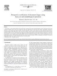
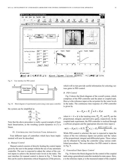
Fig. 9. User interface <str<strong>on</strong>g>for</str<strong>on</strong>g> PID <str<strong>on</strong>g>c<strong>on</strong>trol</str<strong>on</strong>g>.<br />
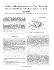
Fig. 10. Block diagram <str<strong>on</strong>g>of</str<strong>on</strong>g> experimental system using a state-space <str<strong>on</strong>g>c<strong>on</strong>trol</str<strong>on</strong>g>ler.<br />
the system can be simplified as<br />
Note that the above procedure is really a good example <str<strong>on</strong>g>of</str<strong>on</strong>g> feedback<br />
linearizati<strong>on</strong>, as the resulting system dynamics in (7) is<br />
linear.<br />
IV. CONTROLLING THE COUPLED TANK APPARATUS<br />
Four different types <str<strong>on</strong>g>of</str<strong>on</strong>g> <str<strong>on</strong>g>c<strong>on</strong>trol</str<strong>on</strong>g>lers which have been implemented<br />
will now be described.<br />
A. Manual C<strong>on</strong>trol<br />
Manual <str<strong>on</strong>g>c<strong>on</strong>trol</str<strong>on</strong>g> c<strong>on</strong>sists <str<strong>on</strong>g>of</str<strong>on</strong>g> directly feeding the <str<strong>on</strong>g>c<strong>on</strong>trol</str<strong>on</strong>g> inputs<br />
given by the user to the pumps without the use <str<strong>on</strong>g>of</str<strong>on</strong>g> any automatic<br />
<str<strong>on</strong>g>c<strong>on</strong>trol</str<strong>on</strong>g>ler. The user is expected to adjust the values <str<strong>on</strong>g>of</str<strong>on</strong>g> the <str<strong>on</strong>g>c<strong>on</strong>trol</str<strong>on</strong>g><br />
inputs to achieve the desired water levels in the tanks. The<br />
user interface <str<strong>on</strong>g>for</str<strong>on</strong>g> manual <str<strong>on</strong>g>c<strong>on</strong>trol</str<strong>on</strong>g> is shown in Fig. 7. Note that<br />
this can be used to determine critical frequencies <str<strong>on</strong>g>of</str<strong>on</strong>g> the process,<br />
(7)<br />
which will in turn provide useful in<str<strong>on</strong>g>for</str<strong>on</strong>g>mati<strong>on</strong> <str<strong>on</strong>g>for</str<strong>on</strong>g> selecting various<br />
gains in PID <str<strong>on</strong>g>c<strong>on</strong>trol</str<strong>on</strong>g>.<br />
B. PID C<strong>on</strong>trol<br />
Fig. 8 shows the block diagram <str<strong>on</strong>g>of</str<strong>on</strong>g> the overall system, which<br />
comprises <str<strong>on</strong>g>of</str<strong>on</strong>g> the PID <str<strong>on</strong>g>c<strong>on</strong>trol</str<strong>on</strong>g>ler and the plant or coupled tank.<br />
Here is the reference input or the set points <str<strong>on</strong>g>for</str<strong>on</strong>g> the water levels<br />
in the tanks. The c<strong>on</strong>tinuous time resp<strong>on</strong>se <str<strong>on</strong>g>of</str<strong>on</strong>g> a PID <str<strong>on</strong>g>c<strong>on</strong>trol</str<strong>on</strong>g>ler<br />
is given by<br />
where is the tracking error, , , and are the<br />
proporti<strong>on</strong>al, integral, and derivative gains, respectively. In the<br />
coupled tank experiment, the PID <str<strong>on</strong>g>c<strong>on</strong>trol</str<strong>on</strong>g>ler is realized through<br />
a s<str<strong>on</strong>g>of</str<strong>on</strong>g>tware program and the appropriate discrete-time input is<br />
While PID <str<strong>on</strong>g>c<strong>on</strong>trol</str<strong>on</strong>g> is selected, the user is expected to input the<br />
values <str<strong>on</strong>g>of</str<strong>on</strong>g> the two reference inputs (set points) and the values<br />
<str<strong>on</strong>g>of</str<strong>on</strong>g> the proporti<strong>on</strong>al, integral and differential gains. These values<br />
can be obtained by tuning the <str<strong>on</strong>g>c<strong>on</strong>trol</str<strong>on</strong>g>ler using various established<br />
procedures. The user interface <str<strong>on</strong>g>for</str<strong>on</strong>g> PID <str<strong>on</strong>g>c<strong>on</strong>trol</str<strong>on</strong>g> is shown<br />
in Fig. 9.<br />
C. Generalized State-Space C<strong>on</strong>trol<br />
Fig. 10 shows the block diagram <str<strong>on</strong>g>for</str<strong>on</strong>g> the <str<strong>on</strong>g>c<strong>on</strong>trol</str<strong>on</strong>g> <str<strong>on</strong>g>of</str<strong>on</strong>g> the coupled<br />
tank using a generalized <str<strong>on</strong>g>c<strong>on</strong>trol</str<strong>on</strong>g>ler modeled in state space. Here,<br />
is the reference input, is the measured output <str<strong>on</strong>g>of</str<strong>on</strong>g> the coupled-<br />
(8)<br />
(9)