IDG-F_cat_en

You also want an ePaper? Increase the reach of your titles
YUMPU automatically turns print PDFs into web optimized ePapers that Google loves.
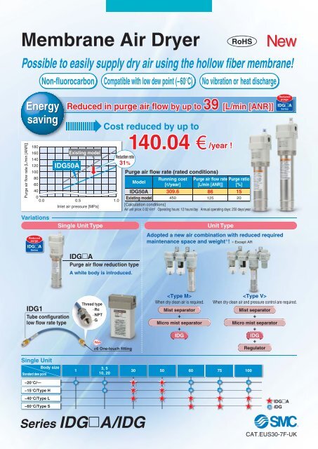
Membrane Air Dryer<br />
Possible to easily supply dry air using the hollow fiber membrane!<br />
Non-fluorocarbon<br />
Compatible with low dew point (–60°C)<br />
RoHS<br />
No vibration or heat discharge<br />
New<br />
Energy<br />
saving<br />
Reduced in purge air flow by up to 39 [L/min [ANR]]<br />
Cost reduced by up to<br />
Reduced<br />
purge<br />
<strong>IDG</strong>A<br />
Series<br />
Purge air flow rate [L/min [ANR]]<br />
180<br />
160<br />
Existing model<br />
140<br />
120 <strong>IDG</strong>50A<br />
100<br />
80<br />
60<br />
40<br />
0<br />
0.0 0.5 1.0<br />
Inlet air pressure [MPa]<br />
Variations<br />
Reduced<br />
purge<br />
<strong>IDG</strong>A<br />
Series<br />
Single Unit Type<br />
Reduction ratio<br />
31%<br />
Purge air flow rate (rated conditions)<br />
<strong>IDG</strong>50A<br />
Existing model<br />
<strong>IDG</strong>A<br />
Purge air flow reduction type<br />
A white body is introduced.<br />
140.04 € /year !<br />
Model<br />
Running cost<br />
[€/year]<br />
309.6<br />
450<br />
Purge air flow rate<br />
[L/min [ANR]]<br />
86<br />
125<br />
Unit Type<br />
Purge ratio<br />
[%]<br />
Adopted a new air combination with reduced required<br />
maint<strong>en</strong>ance space and weight∗! ∗ Except AR<br />
15<br />
20<br />
[Calculation conditions]<br />
Air unit price: 0.02 €/m 3 Operating hours: 12 hours/day Annual operating days: 250 days/year<br />
<strong>IDG</strong>1<br />
Tube configuration<br />
low flow rate type<br />
Thread type<br />
·Rc<br />
·NPT<br />
·G<br />
ø6 One-touch fitting<br />
<br />
Wh<strong>en</strong> dry clean air is required.<br />
Mist separator<br />
+<br />
Micro mist separator<br />
+<br />
<strong>IDG</strong><br />
<br />
Wh<strong>en</strong> dry clean air and pressure control are required.<br />
Mist separator<br />
+<br />
Micro mist separator<br />
+<br />
<strong>IDG</strong><br />
+<br />
Regulator<br />
Single Unit<br />
Body size<br />
Standard dew point<br />
1<br />
3, 5<br />
10, 20<br />
30 50 60 75 100<br />
−20°C/—<br />
−15°C/Type H<br />
−40°C/Type L<br />
−60°C/Type S<br />
Series <strong>IDG</strong>A/<strong>IDG</strong><br />
<strong>IDG</strong>A<br />
<strong>IDG</strong><br />
CAT.EUS30-7F-UK
Membrane Air Dryer<br />
Space<br />
saving<br />
Total l<strong>en</strong>gth is short<strong>en</strong>ed.<br />
Series <strong>IDG</strong>30A to 100A<br />
Max. 59 mm<br />
Size<br />
Short<strong>en</strong>ed dim<strong>en</strong>sion<br />
<strong>IDG</strong>A<br />
Existing model<br />
30<br />
2<br />
291<br />
271<br />
50<br />
7<br />
330<br />
315<br />
∗ Standard dew point: –40°C/L, –60°C/S<br />
60<br />
44<br />
348<br />
392<br />
75<br />
54<br />
418<br />
472<br />
(mm)<br />
100<br />
59<br />
483<br />
542<br />
Flexible mounting ori<strong>en</strong>tation<br />
Series <strong>IDG</strong>1<br />
Easy to install in narrow spaces!<br />
ø6 One-touch fitting<br />
Inspection<br />
equipm<strong>en</strong>t<br />
Thread type<br />
·Rc<br />
· NPT<br />
·G<br />
Reduced<br />
purge<br />
<strong>IDG</strong>A<br />
Series<br />
483 mm<br />
59 mm<br />
<strong>IDG</strong>100LA, 100SA<br />
Existing model<br />
542 mm<br />
¡Min. b<strong>en</strong>ding radius: 35 mm<br />
¡Possible to dehumidify<br />
like a tube.<br />
¡Weight: 45 g<br />
High<br />
performance<br />
Time to reach the standard dew point<br />
Short<strong>en</strong>ed by 40 minutes<br />
Under SMC test condition<br />
Reduced<br />
purge<br />
<strong>IDG</strong>A<br />
Series<br />
Model<br />
<strong>IDG</strong>100SA<br />
Existing model<br />
Time to reach the standard dew point (minutes)<br />
60 90<br />
60<br />
40 minutes<br />
100<br />
Dew point indi<strong>cat</strong>or visually<br />
confirms air drying.<br />
(Except <strong>IDG</strong>1)<br />
(Semi-standard: <strong>IDG</strong>3, <strong>IDG</strong>5, <strong>IDG</strong>3H, <strong>IDG</strong>5H)<br />
Colour of the dew point indi<strong>cat</strong>or<br />
Normal operating: Blue<br />
Initial state: White/Pink<br />
Dew point indi<strong>cat</strong>or<br />
Model with fitting for purge<br />
air discharge is also available.<br />
Wh<strong>en</strong> purge air discharge is undesirable in the area<br />
around the membrane air dryer, it can be discharged<br />
to atmosphere via tubing (semi-standard).<br />
Fitting for exhausting purge<br />
air for dew point indi<strong>cat</strong>or<br />
Fitting for exhausting purge air<br />
for dehumidifi<strong>cat</strong>ion<br />
Reduced in purge air discharge<br />
noise with built-in sil<strong>en</strong>cer<br />
(<br />
Except <strong>IDG</strong>1, <strong>IDG</strong>3, <strong>IDG</strong>3H, <strong>IDG</strong>5,<br />
)<br />
<strong>IDG</strong>5H, <strong>IDG</strong>30A, <strong>IDG</strong>30HA, <strong>IDG</strong>30LA,<br />
<strong>IDG</strong>50A, <strong>IDG</strong>50HA, <strong>IDG</strong>50LA<br />
Features 1
Series <strong>IDG</strong>A/<strong>IDG</strong><br />
Dehumidifi<strong>cat</strong>ion Principle<br />
The membrane air dryer uses hollow fibers composed of a macro molecular membrane through<br />
which moisture passes easily, but is difficult for air (oxyg<strong>en</strong> and nitrog<strong>en</strong>) to pass through.<br />
Wh<strong>en</strong> humid, compressed air is<br />
supplied to the inside of the hollow<br />
fibers, only moisture permeates the<br />
membrane and moves to the outside<br />
due to the pressure differ<strong>en</strong>ce<br />
betwe<strong>en</strong> the moisture inside and<br />
outside of the fibers. The compressed<br />
air becomes dry air and<br />
continues out of the dryer. Part of<br />
the dry air from the outlet side is<br />
passed through a very small orifice<br />
to reduce the pressure and purge<br />
the outside of the hollow fibers. The<br />
moisture which permeated to the<br />
outside of the hollow fibers is discharged<br />
to the atmosphere by this<br />
purge air. In this way, the partial<br />
pressure outside of the hollow fibers<br />
remains low and dehumidifi<strong>cat</strong>ion<br />
is continuously performed.<br />
Air (oxyg<strong>en</strong>, nitrog<strong>en</strong>, etc.) Dry air<br />
Moisture<br />
Orifice<br />
Purge air<br />
Hollow fiber<br />
Humid compressed air<br />
Machine Tool<br />
Appli<strong>cat</strong>ion Examples<br />
Measuring Machine<br />
Semiconductor-related<br />
Manufacturing Equipm<strong>en</strong>t<br />
Powder Coating<br />
Food Machinery<br />
Packaging Machine<br />
(sealing of film and paper package)<br />
Others<br />
D<strong>en</strong>tal equipm<strong>en</strong>t<br />
Chemical analysis<br />
equipm<strong>en</strong>t<br />
Ozonizers, Hydrog<strong>en</strong> gas<br />
g<strong>en</strong>erating equipm<strong>en</strong>t<br />
Printed circuit board IC<br />
mounting machines<br />
Fine particle drying,<br />
Transfer equipm<strong>en</strong>t<br />
Drying and cleaning<br />
of precision parts<br />
Cond<strong>en</strong>sation prev<strong>en</strong>tion<br />
in control panels<br />
G<strong>en</strong>eral pneumatic equipm<strong>en</strong>t<br />
and pneumatic tools<br />
Features 2
Series Variations<br />
Meets a wide variety of flow rates (10 to 1000 L/min [ANR]) and dew points (Atmospheric pressure dew point: –15°C to –60°C).<br />
Single Unit Type<br />
Standard dew point: –20°C Standard dew point: –15°C Standard dew point: –40°C Standard dew point: –60°C<br />
Series<br />
Outlet air flow rate<br />
[L/min [ANR]]<br />
Series<br />
Outlet air flow rate<br />
[L/min [ANR]]<br />
Series<br />
Outlet air flow rate<br />
[L/min [ANR]]<br />
Series<br />
Outlet air flow rate<br />
[L/min [ANR]]<br />
<strong>IDG</strong>1<br />
10<br />
<strong>IDG</strong>3<br />
25<br />
<strong>IDG</strong>3H<br />
25<br />
<strong>IDG</strong>5<br />
50<br />
<strong>IDG</strong>5H<br />
50<br />
<strong>IDG</strong>10<br />
<strong>IDG</strong>20<br />
100<br />
200<br />
<strong>IDG</strong>10H<br />
<strong>IDG</strong>20H<br />
100<br />
200<br />
Page 1<br />
Page 2<br />
<strong>IDG</strong>30A<br />
300<br />
<strong>IDG</strong>30HA<br />
300<br />
<strong>IDG</strong>30LA<br />
75<br />
<strong>IDG</strong>50A<br />
500<br />
<strong>IDG</strong>50HA<br />
500<br />
<strong>IDG</strong>50LA<br />
110<br />
<strong>IDG</strong>60<br />
600<br />
<strong>IDG</strong>60H<br />
600<br />
<strong>IDG</strong>60LA<br />
170<br />
<strong>IDG</strong>60SA<br />
50<br />
<strong>IDG</strong>75<br />
750<br />
<strong>IDG</strong>75H<br />
750<br />
<strong>IDG</strong>75LA<br />
240<br />
<strong>IDG</strong>75SA<br />
100<br />
<strong>IDG</strong>100<br />
1000<br />
<strong>IDG</strong>100H<br />
1000<br />
<strong>IDG</strong>100LA<br />
300<br />
<strong>IDG</strong>100SA<br />
150<br />
= Reduced purge<br />
Note) Standard dew point: Outlet air atmospheric pressure dew point under standard performance conditions<br />
Outlet air flow rate: Values under standard performance conditions<br />
Features 3
Series <strong>IDG</strong>A/<strong>IDG</strong><br />
Unit Type<br />
<br />
A mist separator, micro mist separator, or micro mist separator with pre-filter combined with a single unit<br />
Standard dew point: –20°C Standard dew point: –15°C Standard dew point: –40°C Standard dew point: –60°C<br />
Series<br />
Outlet air flow rate<br />
[L/min [ANR]]<br />
Series<br />
Outlet air flow rate<br />
[L/min [ANR]]<br />
Series<br />
Outlet air flow rate<br />
[L/min [ANR]]<br />
Series<br />
Outlet air flow rate<br />
[L/min [ANR]]<br />
<strong>IDG</strong>3M4<br />
25<br />
<strong>IDG</strong>3HM4<br />
25<br />
<strong>IDG</strong>5M4<br />
50<br />
<strong>IDG</strong>5HM4<br />
50<br />
<strong>IDG</strong>10M4<br />
<strong>IDG</strong>20M4<br />
<strong>IDG</strong>30AM4<br />
100<br />
200<br />
300<br />
<strong>IDG</strong>10HM4<br />
<strong>IDG</strong>20HM4<br />
<strong>IDG</strong>30HAM4<br />
100<br />
200<br />
300<br />
<strong>IDG</strong>30LAM4<br />
75<br />
Page 15<br />
Page 16<br />
<strong>IDG</strong>50AM4<br />
500<br />
<strong>IDG</strong>50HAM4<br />
500<br />
<strong>IDG</strong>50LAM4<br />
110<br />
<strong>IDG</strong>60M2<br />
600<br />
<strong>IDG</strong>60HM2<br />
600<br />
<strong>IDG</strong>60LAM4<br />
170<br />
<strong>IDG</strong>60SAM4<br />
50<br />
<strong>IDG</strong>75M2<br />
750<br />
<strong>IDG</strong>75HM2<br />
750<br />
<strong>IDG</strong>75LAM4<br />
240<br />
<strong>IDG</strong>75SAM4<br />
100<br />
<strong>IDG</strong>100M2<br />
1000<br />
<strong>IDG</strong>100HM2<br />
1000<br />
<strong>IDG</strong>100LAM4<br />
300<br />
<strong>IDG</strong>100SAM4<br />
150<br />
∗ Rated conditions: Inlet air pressure 0.7 MPa, Inlet air temperature 25°C<br />
<br />
A regulator combined with the type M<br />
Standard dew point: –20°C Standard dew point: –15°C Standard dew point: –40°C Standard dew point: –60°C<br />
Series<br />
Outlet air flow rate<br />
[L/min [ANR]]<br />
Series<br />
Outlet air flow rate<br />
[L/min [ANR]]<br />
Series<br />
Outlet air flow rate<br />
[L/min [ANR]]<br />
Series<br />
Outlet air flow rate<br />
[L/min [ANR]]<br />
<strong>IDG</strong>3V4<br />
25<br />
<strong>IDG</strong>3HV4<br />
25<br />
<strong>IDG</strong>5V4<br />
50<br />
<strong>IDG</strong>5HV4<br />
50<br />
<strong>IDG</strong>10V4<br />
<strong>IDG</strong>20V4<br />
<strong>IDG</strong>30AV4<br />
100<br />
200<br />
300<br />
<strong>IDG</strong>10HV4<br />
<strong>IDG</strong>20HV4<br />
<strong>IDG</strong>30HAV4<br />
100<br />
200<br />
300<br />
<strong>IDG</strong>30LAV4<br />
75<br />
Page 15<br />
Page 16<br />
<strong>IDG</strong>50AV4<br />
500<br />
<strong>IDG</strong>50HAV4<br />
500<br />
<strong>IDG</strong>50LAV4<br />
110<br />
<strong>IDG</strong>60V4<br />
600<br />
<strong>IDG</strong>60HV4<br />
600<br />
<strong>IDG</strong>60LAV4<br />
170<br />
<strong>IDG</strong>60SAV4<br />
50<br />
<strong>IDG</strong>75V4<br />
750<br />
<strong>IDG</strong>75HV4<br />
750<br />
<strong>IDG</strong>75LAV4<br />
240<br />
<strong>IDG</strong>75SAV4<br />
100<br />
<strong>IDG</strong>100V4 1000 <strong>IDG</strong>100HV4 1000 <strong>IDG</strong>100LAV4<br />
∗ Rated conditions: Inlet air pressure 0.7 MPa, Inlet air temperature 25°C<br />
300<br />
<strong>IDG</strong>100SAV4<br />
150<br />
Made to Order<br />
Symbol<br />
-X016<br />
Specifi<strong>cat</strong>ions<br />
With elem<strong>en</strong>t service indi<strong>cat</strong>or<br />
-X017<br />
With micro mist separator regulator<br />
-X032<br />
With differ<strong>en</strong>tial pressure gauge<br />
Features 4
Membrane Air Dryer<br />
Single Unit Type<br />
Series<br />
Reduced<br />
purge<br />
<strong>IDG</strong>A<br />
Series<br />
Standard dew point −20°C, −15°C, −40°C, −60°C<br />
<strong>IDG</strong>A<br />
RoHS<br />
How to Order<br />
Reduced<br />
purge<br />
<strong>IDG</strong>A<br />
Series<br />
<strong>IDG</strong> 30 A 03<br />
Size<br />
30<br />
50<br />
60<br />
75<br />
100<br />
Standard dew point temperature/Outlet air flow rate<br />
Symbol<br />
Standard Flow rate by size, Outlet air flow rate [L/min [ANR]]<br />
dew point<br />
[°C] 30 50 60 75 100<br />
—<br />
H<br />
−20<br />
−15<br />
300<br />
300<br />
500<br />
500<br />
Select from Series <strong>IDG</strong><br />
(page 2)<br />
L<br />
S<br />
−40<br />
−60<br />
75<br />
—<br />
110<br />
—<br />
170<br />
50<br />
240<br />
100<br />
300<br />
150<br />
Symbol<br />
Thread type<br />
Symbol Type<br />
— Rc<br />
N NPT<br />
F G<br />
Semi-standardd<br />
Symbol Specifi<strong>cat</strong>ions<br />
— None (Standard)<br />
P With fitting for purge air discharge<br />
R Flow direction (Right → Left)<br />
Note) In the case of more than one symbol,<br />
indi<strong>cat</strong>e them alphabetically.<br />
Accessory<br />
Symbol Specifi<strong>cat</strong>ions<br />
— None (Standard)<br />
B With bracket<br />
Note) Wh<strong>en</strong> symbol: B is indi<strong>cat</strong>ed, a bracket<br />
assembly with a part number shown to<br />
the left below is included as an accessory.<br />
Bracket Assembly (Accessory)/Part No.<br />
Part no.<br />
Applicable model<br />
BM64 <strong>IDG</strong>30A, <strong>IDG</strong>50A<br />
BM65 <strong>IDG</strong>60A, <strong>IDG</strong>75A, <strong>IDG</strong>100A<br />
∗ With hexagon socket head cap screws (2 pcs.) and<br />
spring washers (2 pcs.)<br />
Port size<br />
Symbol<br />
02<br />
03<br />
04<br />
Port<br />
size<br />
1/4<br />
3/8<br />
1/2<br />
30<br />
<br />
<br />
—<br />
50<br />
<br />
<br />
—<br />
Size<br />
60<br />
—<br />
<br />
<br />
75<br />
—<br />
<br />
<br />
100<br />
—<br />
<br />
<br />
1
Membrane Air Dryer<br />
Single Unit Type<br />
Series <strong>IDG</strong><br />
How to Order<br />
<strong>IDG</strong> 10 02<br />
RoHS<br />
Single Unit Type<br />
Size<br />
1<br />
3<br />
5<br />
10<br />
20<br />
60<br />
75<br />
100<br />
Standard dew point temperature/Outlet air flow rate<br />
Standard Flow rate by size, Outlet air flow rate [L/min [ANR]]<br />
Symbol dew point<br />
[°C] 1 3 5 10 20 60 75 100<br />
—<br />
H<br />
−20<br />
−15<br />
10<br />
—<br />
25<br />
25<br />
50<br />
50<br />
100<br />
100<br />
200<br />
200<br />
600<br />
600<br />
750<br />
750<br />
1000<br />
1000<br />
L −40 — — — — — Select from<br />
S −60 — — — — — Series <strong>IDG</strong>A (page 1)<br />
Symbol<br />
Bracket Assembly (Accessory)/Part No.<br />
Part no.<br />
Applicable model<br />
BM59 <strong>IDG</strong>3, 5<br />
BM61 <strong>IDG</strong>10<br />
BM63 <strong>IDG</strong>20<br />
BM65 <strong>IDG</strong>60, 75, 100<br />
∗ With hexagon socket head cap screws (2 pcs.) and<br />
spring washers (2 pcs.)<br />
Thread type/One-touch fitting<br />
Symbol Type<br />
—<br />
Rc<br />
N<br />
NPT<br />
F<br />
G<br />
C Note) ø6 One-touch fitting<br />
Note) Size 1 only<br />
Symbol<br />
—<br />
P<br />
R<br />
S<br />
Port size/Applicable tubing O.D.<br />
Symbol<br />
01<br />
02<br />
03<br />
04<br />
06<br />
Accessory<br />
Symbol Specifi<strong>cat</strong>ions<br />
— None (Standard)<br />
B With bracket (Except <strong>IDG</strong>1)<br />
Note) Wh<strong>en</strong> symbol: B is indi<strong>cat</strong>ed, a<br />
bracket assembly with a part number<br />
shown to the left below is included<br />
as an accessory.<br />
Port<br />
size<br />
1/8<br />
1/4<br />
3/8<br />
1/2<br />
ø6<br />
Specifi<strong>cat</strong>ions<br />
Piping type<br />
Size<br />
Thread<br />
One-touch<br />
fitting<br />
None (Standard)<br />
With fitting for purge air discharge<br />
Flow direction (Right → Left)<br />
With dew point indi<strong>cat</strong>or<br />
1<br />
—<br />
<br />
—<br />
—<br />
<br />
3<br />
<br />
<br />
—<br />
—<br />
—<br />
5<br />
<br />
<br />
—<br />
—<br />
—<br />
10<br />
—<br />
<br />
<br />
—<br />
—<br />
20<br />
—<br />
<br />
<br />
—<br />
—<br />
60<br />
—<br />
—<br />
<br />
<br />
—<br />
75 100<br />
— —<br />
— —<br />
— —<br />
<br />
—<br />
—<br />
Semi-standard<br />
Size<br />
1 3 5 10 20 60 75 100<br />
<br />
<br />
— <br />
— Standard equipm<strong>en</strong>t<br />
Note) In the case of more than one symbol, indi<strong>cat</strong>e them alphabetically.<br />
M<br />
Specific Product<br />
Precautions Made to Order Model Selection Unit Type<br />
V<br />
2
Series<br />
Reduced<br />
purge<br />
<strong>IDG</strong>A<br />
Series<br />
<strong>IDG</strong>A/<strong>IDG</strong><br />
Standard Specifi<strong>cat</strong>ions/Single Unit Type (Standard dew point −20°C, −15°C)<br />
Standard dew point…−20°C<br />
Range of operating<br />
conditions<br />
Standard<br />
performance<br />
Model<br />
Fluid<br />
Inlet air pressure [MPa]<br />
Inlet air temperature [°C] Note 1)<br />
Ambi<strong>en</strong>t temperature [°C] Note 1)<br />
Outlet air atmospheric<br />
pressure dew point [°C]<br />
Inlet air flow rate [L/min [ANR]] Note 2)<br />
Outlet air flow rate [L/min [ANR]]<br />
Purge air flow rate [L/min [ANR]] Note 3)<br />
Inlet air pressure [MPa]<br />
Inlet air temperature [°C]<br />
Inlet air saturation temperature [°C]<br />
Ambi<strong>en</strong>t temperature [°C]<br />
Dew point indi<strong>cat</strong>or purge air flow rate<br />
Port size<br />
Applicable tubing O.D.<br />
Standard performance<br />
conditions<br />
Weight [kg]<br />
(With bracket)<br />
1/4<br />
—<br />
0.11<br />
<strong>IDG</strong>1 <strong>IDG</strong>3 <strong>IDG</strong>5 <strong>IDG</strong>10 <strong>IDG</strong>20 <strong>IDG</strong>30A <strong>IDG</strong>50A <strong>IDG</strong>60 <strong>IDG</strong>75<br />
Compressed air<br />
0.3 to 0.85<br />
0.3 to 1.0<br />
−5 to 55<br />
−5 to 50<br />
−5 to 55<br />
−5 to 50<br />
12.5<br />
10<br />
2.5<br />
31<br />
25<br />
6<br />
62<br />
50<br />
12<br />
125<br />
100<br />
25<br />
−20<br />
250<br />
200<br />
50<br />
0.7<br />
25<br />
25<br />
25<br />
—<br />
1 L/min [ANR] (Inlet air pressure at 0.7 MPa)<br />
—<br />
1/8, 1/4<br />
1/4, 3/8 3/8, 1/2 1/2<br />
ø6 —<br />
— — — — — — —<br />
0.05<br />
0.25<br />
(0.31)<br />
Note 1) Wh<strong>en</strong> using the product in the temperature range betwe<strong>en</strong> –5°C and 5°C, prev<strong>en</strong>t water droplets from <strong>en</strong>tering the inlet port. (No freezing of the fluid)<br />
Note 2) “ANR” indi<strong>cat</strong>es the flow rate converted to the value at 20°C, under the atmospheric pressure and the state of relative humidity 65%.<br />
Note 3) Includes 1 L/min [ANR] of purge air flow (Inlet air pressure at 0.7 MPa) for the dew point indi<strong>cat</strong>or (except <strong>IDG</strong>1, 3, 5).<br />
0.43<br />
(0.51)<br />
0.66<br />
(0.76)<br />
360<br />
300<br />
60<br />
0.78<br />
(0.91)<br />
586<br />
500<br />
86<br />
0.81<br />
(0.94)<br />
725<br />
600<br />
125<br />
1.50<br />
(1.65)<br />
900<br />
750<br />
150<br />
1.50<br />
(1.65)<br />
<strong>IDG</strong>100<br />
1190<br />
1000<br />
190<br />
1.55<br />
(1.70)<br />
Standard dew point…−15°C/Type H<br />
Range of operating<br />
conditions<br />
Standard<br />
performance<br />
Standard performance<br />
conditions<br />
Model <strong>IDG</strong>3H <strong>IDG</strong>5H <strong>IDG</strong>10H <strong>IDG</strong>20H <strong>IDG</strong>30HA <strong>IDG</strong>50HA <strong>IDG</strong>60H <strong>IDG</strong>75H <strong>IDG</strong>100H<br />
Fluid<br />
Compressed air<br />
Inlet air pressure [MPa]<br />
0.3 to 0.85<br />
0.3 to 1.0<br />
Inlet air temperature [°C] Note 1)<br />
−5 to 55<br />
−5 to 50<br />
Ambi<strong>en</strong>t temperature [°C] Note 1)<br />
−5 to 55<br />
−5 to 50<br />
Outlet air atmospheric<br />
pressure dew point [°C]<br />
−15<br />
Inlet air flow rate [L/min [ANR]] Note 2)<br />
Outlet air flow rate [L/min [ANR]]<br />
Purge air flow rate [L/min [ANR]] Note 3)<br />
Inlet air pressure [MPa]<br />
Inlet air temperature [°C]<br />
Inlet air saturation temperature [°C]<br />
Ambi<strong>en</strong>t temperature [°C]<br />
Dew point indi<strong>cat</strong>or purge air flow rate<br />
Port size<br />
Weight [kg]<br />
(With bracket)<br />
28<br />
25<br />
3<br />
56<br />
50<br />
6<br />
111<br />
100<br />
11<br />
222<br />
200<br />
22<br />
329<br />
300<br />
550<br />
500<br />
50<br />
665<br />
600<br />
65<br />
29<br />
0.7<br />
25<br />
25<br />
25<br />
1 L/min [ANR] (Inlet air pressure at 0.7 MPa)<br />
830<br />
750<br />
80<br />
—<br />
1/8, 1/4 1/4, 3/8 3/8, 1/2 1/2<br />
0.25<br />
0.43 0.66 0.78 0.81 1.50 1.50<br />
(0.31)<br />
(0.51) (0.76) (0.91) (0.94) (1.65) (1.65)<br />
Note 1) Wh<strong>en</strong> using the product in the temperature range betwe<strong>en</strong> –5°C and 5°C, prev<strong>en</strong>t water droplets from <strong>en</strong>tering the inlet port. (No freezing of the fluid)<br />
Note 2) “ANR” indi<strong>cat</strong>es the flow rate converted to the value at 20°C, under the atmospheric pressure and the state of relative humidity 65%.<br />
Note 3) Includes 1 L/min [ANR] of purge air flow (Inlet air pressure at 0.7 MPa) for the dew point indi<strong>cat</strong>or (except <strong>IDG</strong>3H, 5H).<br />
1110<br />
1000<br />
110<br />
1.55<br />
(1.70)<br />
3
Membrane Air Dryer<br />
Single Unit Type<br />
Series<br />
Reduced<br />
purge<br />
<strong>IDG</strong>A<br />
Series<br />
<strong>IDG</strong>A/<strong>IDG</strong><br />
Standard Specifi<strong>cat</strong>ions/Single Unit Type (Standard dew point −40°C, −60°C)<br />
Standard dew point…−40°C/Type L<br />
Range of operating<br />
conditions<br />
Standard<br />
performance<br />
Model <strong>IDG</strong>30LA <strong>IDG</strong>50LA <strong>IDG</strong>60LA <strong>IDG</strong>75LA <strong>IDG</strong>100LA<br />
Fluid<br />
Compressed air<br />
Inlet air pressure [MPa]<br />
0.3 to 1.0<br />
Inlet air temperature [°C] Note 1)<br />
−5 to 50<br />
Ambi<strong>en</strong>t temperature [°C] Note 1)<br />
−5 to 50<br />
Outlet air atmospheric<br />
pressure dew point [°C]<br />
−40<br />
Inlet air flow rate [L/min [ANR]] Note 2)<br />
Outlet air flow rate [L/min [ANR]]<br />
Purge air flow rate [L/min [ANR]] Note 3)<br />
Inlet air pressure [MPa]<br />
Inlet air temperature [°C]<br />
Inlet air saturation temperature [°C]<br />
Ambi<strong>en</strong>t temperature [°C]<br />
Dew point indi<strong>cat</strong>or purge air flow rate<br />
Port size<br />
Weight [kg]<br />
(With bracket)<br />
Standard performance<br />
conditions<br />
93<br />
75<br />
18<br />
0.78<br />
(0.91)<br />
135<br />
110<br />
25<br />
224<br />
170<br />
54<br />
0.7<br />
25<br />
25<br />
25<br />
308<br />
240<br />
68<br />
1 L/min [ANR] (Inlet air pressure at 0.7 MPa)<br />
1/4, 3/8 3/8, 1/2<br />
0.81 1.56 1.69<br />
(0.94) (1.71) (1.84)<br />
Note 1) Wh<strong>en</strong> using the product in the temperature range betwe<strong>en</strong> –5°C and 5°C, prev<strong>en</strong>t water droplets from <strong>en</strong>tering the inlet port. (No freezing of the fluid)<br />
Note 2) “ANR” indi<strong>cat</strong>es the flow rate converted to the value at 20°C, under the atmospheric pressure and the state of relative humidity 65%.<br />
Note 3) Includes 1 L/min [ANR] of purge air flow (Inlet air pressure at 0.7 MPa) for the dew point indi<strong>cat</strong>or.<br />
Standard dew point…−60°C/Type S<br />
Range of operating<br />
conditions<br />
Standard<br />
performance<br />
Standard performance<br />
conditions<br />
Model <strong>IDG</strong>60SA <strong>IDG</strong>75SA <strong>IDG</strong>100SA<br />
Fluid<br />
Inlet air pressure [MPa]<br />
Inlet air temperature [°C] Note 1)<br />
Ambi<strong>en</strong>t temperature [°C] Note 1)<br />
Compressed air<br />
0.3 to 1.0<br />
−5 to 50<br />
−5 to 50<br />
Outlet air atmospheric<br />
pressure dew point [°C]<br />
−60<br />
Inlet air flow rate [L/min [ANR]] Note 2)<br />
Outlet air flow rate [L/min [ANR]]<br />
Purge air flow rate [L/min [ANR]] Note 3)<br />
Inlet air pressure [MPa]<br />
Inlet air temperature [°C]<br />
Inlet air saturation temperature [°C]<br />
Ambi<strong>en</strong>t temperature [°C]<br />
Dew point indi<strong>cat</strong>or purge air flow rate<br />
Port size<br />
Weight [kg]<br />
(With bracket)<br />
75<br />
50<br />
25<br />
140<br />
100<br />
230<br />
150<br />
80<br />
40<br />
0.7<br />
25<br />
25<br />
25<br />
1 L/min [ANR] (Inlet air pressure at 0.7 MPa)<br />
3/8, 1/2<br />
1.56<br />
(1.71)<br />
1.69<br />
(1.84)<br />
1.82<br />
(1.97)<br />
Note 1) Wh<strong>en</strong> using the product in the temperature range betwe<strong>en</strong> –5°C and 5°C, prev<strong>en</strong>t water droplets from <strong>en</strong>tering the inlet port. (No freezing of the fluid)<br />
Note 2) “ANR” indi<strong>cat</strong>es the flow rate converted to the value at 20°C, under the atmospheric pressure and the state of relative humidity 65%.<br />
Note 3) Includes 1 L/min [ANR] of purge air flow (Inlet air pressure at 0.7 MPa) for the dew point indi<strong>cat</strong>or.<br />
400<br />
300<br />
100<br />
1.82<br />
(1.97)<br />
M<br />
V<br />
Single Unit Type<br />
Specific Product<br />
Precautions Made to Order Model Selection Unit Type<br />
4
Series<br />
Reduced<br />
purge<br />
<strong>IDG</strong>A<br />
Series<br />
<strong>IDG</strong>A/<strong>IDG</strong><br />
Performance Chart<br />
Conditions: Inlet air temperature 25°C (saturated air), Ambi<strong>en</strong>t temperature 25°C, P1: Inlet air pressure, Tube for purge air discharge (semi-standard: P): None<br />
Note: Correcting outlet air flow rate is required dep<strong>en</strong>ding on inlet air temperature. Refer to page 31 or after for details. For model with fitting for purge air<br />
discharge (semi-standard: P), the outlet air atmospheric pressure dew point may become higher dep<strong>en</strong>ding on the tube l<strong>en</strong>gth for purge air discharge.<br />
For other models, wh<strong>en</strong> the tube l<strong>en</strong>gth is 5 meters or less, a rise of the outlet air atmospheric pressure dew point will be 1°C or less.<br />
Standard dew point…−20°C [Symbol: —], −15°C [Symbol: H]<br />
<strong>IDG</strong>1<br />
<strong>IDG</strong>3, <strong>IDG</strong>3H<br />
Outlet air atmospheric pressure dew point [°C]<br />
0<br />
P1 = 0.3 MPa<br />
−10<br />
P1 = 0.5 MPa<br />
−20<br />
P1 = 0.7 MPa<br />
−30<br />
<strong>IDG</strong>1<br />
−40<br />
0 4 8 12 16<br />
Outlet air flow rate [L/min [ANR]]<br />
Outlet air atmospheric pressure dew point [°C]<br />
P1 = 0.3 MPa<br />
0<br />
P1 = 0.5 MPa<br />
−10<br />
P1 = 0.7 MPa<br />
−20<br />
<strong>IDG</strong>3<br />
−30<br />
<strong>IDG</strong>3H<br />
−40<br />
0 10 20 30 40<br />
Outlet air flow rate [L/min [ANR]]<br />
<strong>IDG</strong>5, <strong>IDG</strong>5H<br />
<strong>IDG</strong>10, <strong>IDG</strong>10H<br />
Outlet air atmospheric pressure dew point [°C]<br />
P1 = 0.3 MPa<br />
0<br />
P1 = 0.5 MPa<br />
−10<br />
P1 = 0.7 MPa<br />
−20<br />
<strong>IDG</strong>5<br />
−30<br />
<strong>IDG</strong>5H<br />
−40<br />
0 20 40 60 80<br />
Outlet air flow rate [L/min [ANR]]<br />
Outlet air atmospheric pressure dew point [°C]<br />
P1 = 0.3 MPa<br />
0<br />
P1 = 0.5 MPa<br />
−10<br />
P1 = 0.7 MPa<br />
−20<br />
<strong>IDG</strong>10<br />
−30<br />
<strong>IDG</strong>10H<br />
−40<br />
0 40 80 120 160<br />
Outlet air flow rate [L/min [ANR]]<br />
<strong>IDG</strong>20, <strong>IDG</strong>20H<br />
<strong>IDG</strong>30A, <strong>IDG</strong>30HA<br />
Outlet air atmospheric pressure dew point [°C]<br />
P1 = 0.3 MPa<br />
0<br />
P1 = 0.5 MPa<br />
−10<br />
P1 = 0.7 MPa<br />
−20<br />
<strong>IDG</strong>20<br />
−30<br />
<strong>IDG</strong>20H<br />
−40<br />
0 100 200 300<br />
Outlet air flow rate [L/min [ANR]]<br />
Outlet air atmospheric pressure dew point [°C]<br />
0<br />
−10<br />
−20<br />
−30<br />
−40<br />
P1 = 0.3 MPa<br />
<strong>IDG</strong>30A<br />
<strong>IDG</strong>30HA<br />
P1 = 0.5 MPa<br />
P1 = 0.7 MPa<br />
−50<br />
0 100 200 300 400 500<br />
Outlet air flow rate [L/min [ANR]]<br />
<strong>IDG</strong>50A, <strong>IDG</strong>50HA<br />
<strong>IDG</strong>60, <strong>IDG</strong>60H<br />
Outlet air atmospheric pressure dew point [°C]<br />
0<br />
P1 = 0.3 MPa<br />
−10<br />
P1 = 0.5 MPa<br />
−20<br />
P1 = 0.7 MPa<br />
−30<br />
<strong>IDG</strong>50A<br />
−40<br />
−50<br />
<strong>IDG</strong>50HA<br />
0 200 400 600 800<br />
Outlet air flow rate [L/min [ANR]]<br />
Outlet air atmospheric pressure dew point [°C]<br />
P1 = 0.3 MPa<br />
0<br />
P1 = 0.5 MPa<br />
−10<br />
P1 = 0.7 MPa<br />
−20<br />
<strong>IDG</strong>60<br />
−30<br />
<strong>IDG</strong>60H<br />
−40<br />
−50<br />
0 200 400 600 800<br />
Outlet air flow rate [L/min [ANR]]<br />
5
Membrane Air Dryer<br />
Single Unit Type<br />
Series<br />
Reduced<br />
purge<br />
<strong>IDG</strong>A<br />
Series<br />
<strong>IDG</strong>A/<strong>IDG</strong><br />
Performance Chart<br />
<strong>IDG</strong>75, <strong>IDG</strong>75H<br />
Outlet air atmospheric pressure dew point [°C]<br />
<strong>IDG</strong>30LA, <strong>IDG</strong>50LA<br />
Outlet air atmospheric pressure dew point [°C]<br />
0<br />
−10<br />
−20<br />
−30<br />
−40<br />
−50<br />
0 200 400 600 800 1000<br />
0<br />
−10<br />
−20<br />
−30<br />
−40<br />
Outlet air flow rate [L/min [ANR]]<br />
−50<br />
<strong>IDG</strong>50LA<br />
−60<br />
<strong>IDG</strong>30LA<br />
−70<br />
0 40 80 120 160<br />
<strong>IDG</strong>75LA, <strong>IDG</strong>75SA<br />
Outlet air atmospheric pressure dew point [°C]<br />
−10<br />
−20<br />
−30<br />
−40<br />
−50<br />
−60<br />
Outlet air flow rate [L/min [ANR]]<br />
<strong>IDG</strong>100, <strong>IDG</strong>100H<br />
Outlet air atmospheric pressure dew point [°C]<br />
0<br />
−10<br />
−20<br />
−30<br />
−40<br />
−50<br />
0 400 800 1200 1600<br />
<strong>IDG</strong>60LA, <strong>IDG</strong>60SA<br />
Outlet air atmospheric pressure dew point [°C]<br />
0<br />
−10<br />
−20<br />
−30<br />
−40<br />
−50<br />
−60<br />
Outlet air flow rate [L/min [ANR]]<br />
−70<br />
0 40 80 120 160 200 240<br />
<strong>IDG</strong>100LA, <strong>IDG</strong>100SA<br />
Outlet air atmospheric pressure dew point [°C]<br />
−10<br />
−20<br />
−30<br />
−40<br />
−50<br />
Outlet air flow rate [L/min [ANR]]<br />
P1 P1<br />
0 = 0.3 MPa<br />
0<br />
= 0.3 MPa<br />
<strong>IDG</strong>75SA<br />
P1 = 0.3 MPa<br />
<strong>IDG</strong>75H<br />
<strong>IDG</strong>75<br />
−70<br />
0 100 200 300<br />
Outlet air flow rate [L/min [ANR]]<br />
P1 = 0.3 MPa<br />
P1 = 0.5 MPa<br />
P1 = 0.7 MPa<br />
Standard dew point…−40°C [Symbol: L], −60°C [Symbol: S]<br />
How to read the Performance Chart and select the model<br />
P1 = 0.5 MPa<br />
P1 = 0.7 MPa<br />
P1 = 0.5 MPa<br />
P1 = 0.7 MPa<br />
<strong>IDG</strong>75LA<br />
Solid lines and dashed lines beginning at the top indi<strong>cat</strong>e the<br />
performance of inlet air temperature at 25°C and inlet air<br />
pressure P1 = 0.3 MPa, 0.5 MPa, 0.7 MPa respectively.<br />
For the inlet air temperature at 25°C and outlet air flow<br />
rate at 45 (L/min)<br />
Model q: The outlet air atmospheric pressure dew point<br />
at P1 = 0.7 MPa: –25 (°C).<br />
For the inlet air temperature at 45°C and outlet air flow<br />
rate at 45 (L/min)<br />
Example) Outlet air flow rate correction factor: 0.75<br />
(The correction factor differs dep<strong>en</strong>ding on the model.<br />
Refer to page 31 or after for details.)<br />
Corrected outlet air flow rate: 45 ÷ 0.75 = 60 (L/min).<br />
Model q: Performing corresponding to the outlet air atmospheric<br />
pressure dew point –20 (°C) at P1 = 0.7 MPa.<br />
Outlet air atmospheric pressure dew point [°C]<br />
0<br />
−10<br />
−15<br />
−20<br />
−25<br />
−30<br />
−40<br />
0<br />
Model w: P1 = 0.3 MPa<br />
<strong>IDG</strong>60SA<br />
<strong>IDG</strong>100SA<br />
<strong>IDG</strong>100H<br />
P1 = 0.3 MPa<br />
<strong>IDG</strong>100<br />
−60<br />
<strong>IDG</strong>100LA<br />
−70<br />
0 100 200 300 400<br />
Outlet air flow rate [L/min [ANR]]<br />
Model q: P1 = 0.3 MPa<br />
45 60<br />
Outlet air flow rate [L/min]<br />
P1 = 0.3 MPa<br />
P1 = 0.3 MPa<br />
P1 = 0.5 MPa<br />
P1 = 0.7 MPa<br />
P1 = 0.5 MPa<br />
P1 = 0.7 MPa<br />
<strong>IDG</strong>60LA<br />
P1 = 0.5 MPa<br />
P1 = 0.7 MPa<br />
Model w: P1 = 0.7 MPa<br />
Model q: P1 = 0.7 MPa<br />
P1 = 0.5 MPa<br />
P1 = 0.7 MPa<br />
6<br />
M<br />
V<br />
Single Unit Type<br />
Specific Product<br />
Precautions Made to Order Model Selection Unit Type
Series<br />
Reduced<br />
purge<br />
<strong>IDG</strong>A<br />
Series<br />
<strong>IDG</strong>A/<strong>IDG</strong><br />
Single Unit Type/Flow-rate Characteristics<br />
Standard dew point…−20°C [Symbol: —], −15°C [Symbol: H]<br />
<strong>IDG</strong>1<br />
<strong>IDG</strong>3, <strong>IDG</strong>3H<br />
Conditions: Inlet air temperature 25°C, P1: Inlet air pressure<br />
0.04<br />
P1 = 0.3 MPa<br />
0.04<br />
P1 = 0.3 MPa<br />
Pressure drop [MPa]<br />
0.03<br />
0.02<br />
0.01<br />
P1 = 0.5 MPa<br />
P1 = 0.7 MPa<br />
Pressure drop [MPa]<br />
0.03<br />
0.02<br />
0.01<br />
P1 = 0.5 MPa<br />
P1 = 0.7 MPa<br />
0.00 0.00<br />
0 4<br />
8<br />
12 16<br />
0 10 20 30 40<br />
Inlet air flow rate [L/min [ANR]]<br />
Inlet air flow rate [L/min [ANR]]<br />
<strong>IDG</strong>5, <strong>IDG</strong>5H<br />
<strong>IDG</strong>10, <strong>IDG</strong>10H<br />
Pressure drop [MPa]<br />
0.04<br />
0.03<br />
0.02<br />
0.01<br />
P1 = 0.3 MPa<br />
P1 = 0.5 MPa<br />
P1 = 0.7 MPa<br />
Pressure drop [MPa]<br />
0.06<br />
0.04<br />
0.02<br />
P1 = 0.3 MPa<br />
P1 = 0.5 MPa<br />
P1 = 0.7 MPa<br />
0.00<br />
0 20 40 60 80<br />
Inlet air flow rate [L/min [ANR]]<br />
<strong>IDG</strong>20, <strong>IDG</strong>20H<br />
0.00<br />
0 40 80 120 160<br />
Inlet air flow rate [L/min [ANR]]<br />
<strong>IDG</strong>30A, <strong>IDG</strong>30HA<br />
0.08<br />
P1 = 0.3 MPa<br />
0.03<br />
P1 = 0.3 MPa<br />
Pressure drop [MPa]<br />
0.06<br />
0.04<br />
0.02<br />
P1 = 0.5 MPa<br />
P1 = 0.7 MPa<br />
Pressure drop [MPa]<br />
0.02<br />
0.01<br />
P1 = 0.5 MPa<br />
P1 = 0.7 MPa<br />
0.00<br />
0.00<br />
0 100 200 300<br />
0 100 200 300 400 500<br />
Inlet air flow rate [L/min [ANR]]<br />
Inlet air flow rate [L/min [ANR]]<br />
<strong>IDG</strong>50A, <strong>IDG</strong>50HA<br />
0.08<br />
P1 = 0.3 MPa<br />
<strong>IDG</strong>60A, <strong>IDG</strong>60HA<br />
0.06<br />
0.05<br />
P1 = 0.3 MPa<br />
Pressure drop [MPa]<br />
0.06<br />
0.04<br />
0.02<br />
P1 = 0.7 MPa<br />
P1 = 0.5 MPa<br />
Pressure drop [MPa]<br />
0.04<br />
0.03<br />
0.02<br />
0.01<br />
P1 = 0.5 MPa<br />
P1 = 0.7 MPa<br />
0.00<br />
0 200 400 600 800<br />
Inlet air flow rate [L/min [ANR]]<br />
0.00<br />
0 200 400 600 800 1000<br />
Inlet air flow rate [L/min [ANR]]<br />
7
Membrane Air Dryer<br />
Single Unit Type<br />
Series<br />
Reduced<br />
purge<br />
<strong>IDG</strong>A<br />
Series<br />
<strong>IDG</strong>A/<strong>IDG</strong><br />
Single Unit Type/Flow-rate Characteristics<br />
Conditions: Inlet air temperature 25°C, P1: Inlet air pressure<br />
Standard dew point…−20°C [Symbol: —], −15°C [Symbol: H]<br />
<strong>IDG</strong>75, <strong>IDG</strong>75H<br />
Pressure drop [MPa]<br />
Pressure drop [MPa]<br />
Pressure drop [MPa]<br />
Pressure drop [MPa]<br />
0.08<br />
0.06<br />
0.04<br />
0.02<br />
0.00<br />
0 200 400 600 800 1000 1200<br />
Inlet air flow rate [L/min [ANR]]<br />
0.01<br />
0.008<br />
0.006<br />
0.004<br />
0.002<br />
0.00 0.00<br />
0 100<br />
200<br />
300<br />
0 100 200 300 400<br />
Inlet air flow rate [L/min [ANR]]<br />
Inlet air flow rate [L/min [ANR]]<br />
0.03<br />
0.02<br />
0.01<br />
P1 = 0.3 MPa<br />
P1 = 0.3 MPa<br />
0.00<br />
0 100 200 300 400<br />
Inlet air flow rate [L/min [ANR]]<br />
P1 = 0.5 MPa<br />
P1 = 0.7 MPa<br />
Standard dew point…−40°C [Symbol: L], −60°C [Symbol: S]<br />
<strong>IDG</strong>30LA<br />
0.03<br />
0.02<br />
0.01<br />
P1 = 0.3 MPa<br />
P1 = 0.5 MPa<br />
P1 = 0.7 MPa<br />
0 100 200 300 400 500<br />
Inlet air flow rate [L/min [ANR]]<br />
<strong>IDG</strong>60LA, <strong>IDG</strong>60SA<br />
<strong>IDG</strong>100LA, <strong>IDG</strong>100SA<br />
P1 = 0.3 MPa<br />
P1 = 0.5 MPa<br />
P1 = 0.7 MPa<br />
P1 = 0.5 MPa<br />
P1 = 0.7 MPa<br />
<strong>IDG</strong>100, <strong>IDG</strong>100H<br />
Pressure drop [MPa]<br />
Pressure drop [MPa]<br />
Pressure drop [MPa]<br />
0.10<br />
0.08<br />
0.06<br />
0.04<br />
0.02<br />
0.00<br />
0 400 800 1200<br />
1600<br />
Inlet air flow rate [L/min [ANR]]<br />
<strong>IDG</strong>50LA<br />
0.06<br />
0.04<br />
0.02<br />
0.02<br />
0.016<br />
0.012<br />
0.008<br />
0.004<br />
P1 = 0.3 MPa<br />
P1 = 0.7 MPa<br />
0.08 P1 = 0.3 MPa<br />
P1 = 0.5 MPa<br />
P1 = 0.5 MPa<br />
P1 = 0.7 MPa<br />
0 200 400 600 800<br />
Inlet air flow rate [L/min [ANR]]<br />
<strong>IDG</strong>75LA, <strong>IDG</strong>75SA<br />
Tube l<strong>en</strong>gth<br />
0 m<br />
1 m<br />
3 m<br />
5 m<br />
<strong>IDG</strong>30A<br />
−20<br />
−19<br />
−17<br />
−16<br />
<strong>IDG</strong>30LA<br />
−40<br />
−39<br />
−38<br />
P1 = 0.3 MPa<br />
P1 = 0.5 MPa<br />
P1 = 0.7 MPa<br />
With fitting for purge air discharge (Semi-standard: P)<br />
As the tube l<strong>en</strong>gth for purge air discharge becomes longer, the outlet air<br />
atmospheric pressure dew point becomes higher. Refer to the table below.<br />
Conditions<br />
Inlet air temperature : 25°C (Saturated)<br />
Ambi<strong>en</strong>t temperature : 25°C<br />
Inlet air pressure : 0.7 MPa<br />
Outlet air flow rate : Flow gained under conditions of the standard<br />
performance. (Refer to pages 3 and 4.)<br />
Tube size<br />
: O.D. ø12 x I.D. ø9<br />
8<br />
M<br />
V<br />
Single Unit Type<br />
Specific Product<br />
Precautions Made to Order Model Selection Unit Type
Series<br />
Reduced<br />
purge<br />
<strong>IDG</strong>A<br />
Series<br />
<strong>IDG</strong>A/<strong>IDG</strong><br />
Purge Air Flow-rate Characteristics<br />
<strong>IDG</strong>1, 3, 5, 10, 20 (Standard dew point −20°C)<br />
<strong>IDG</strong>3H, 5H, 10H, 20H (Standard dew point −15°C)<br />
<strong>IDG</strong>30A, 50A (Standard dew point −20°C)<br />
<strong>IDG</strong>30HA, 50HA (Standard dew point −15°C)<br />
<strong>IDG</strong>30LA, 50LA (Standard dew point −40°C)<br />
125<br />
60<br />
<strong>IDG</strong>20<br />
<strong>IDG</strong>50A<br />
50<br />
100<br />
Purge air flow rate [L/min]<br />
40<br />
30<br />
20<br />
<strong>IDG</strong>10<br />
<strong>IDG</strong>20H<br />
Purge air flow rate [L/min]<br />
75<br />
50<br />
<strong>IDG</strong>30A<br />
<strong>IDG</strong>30HA<br />
10<br />
0<br />
0<br />
<strong>IDG</strong>5<br />
<strong>IDG</strong>10H<br />
<strong>IDG</strong>3, <strong>IDG</strong>5H<br />
<strong>IDG</strong>3H<br />
<strong>IDG</strong>1<br />
0.5 1.0<br />
Inlet air pressure [MPa]<br />
25<br />
<strong>IDG</strong>50HA<br />
<strong>IDG</strong>30LA<br />
<strong>IDG</strong>50LA<br />
0<br />
0 0.5 1.0<br />
Inlet air pressure [MPa]<br />
<strong>IDG</strong>60, 75, 100 (Standard dew point −20°C)<br />
<strong>IDG</strong>60H, 75H, 100H (Standard dew point −15°C)<br />
<strong>IDG</strong>60LA, 75LA, 100LA (Standard dew point −40°C)<br />
<strong>IDG</strong>60SA, 75SA, 100SA (Standard dew point −60°C)<br />
150<br />
280<br />
<strong>IDG</strong>100<br />
<strong>IDG</strong>100LA<br />
240<br />
<strong>IDG</strong>100SA<br />
Purge air flow rate [L/min]<br />
200<br />
160<br />
120<br />
80<br />
<strong>IDG</strong>75<br />
<strong>IDG</strong>60<br />
<strong>IDG</strong>100H<br />
<strong>IDG</strong>75H<br />
<strong>IDG</strong>60H<br />
Purge air flow rate [L/min]<br />
100<br />
50<br />
<strong>IDG</strong>60LA<br />
<strong>IDG</strong>75LA<br />
<strong>IDG</strong>75SA<br />
40<br />
<strong>IDG</strong>60SA<br />
0<br />
0<br />
0.5<br />
1.0<br />
0<br />
0 0.5 1.0<br />
Inlet air pressure [MPa]<br />
Inlet air pressure [MPa]<br />
9
Membrane Air Dryer<br />
Single Unit Type<br />
Series<br />
Reduced<br />
purge<br />
<strong>IDG</strong>A<br />
Series<br />
<strong>IDG</strong>A/<strong>IDG</strong><br />
Construction<br />
<strong>IDG</strong>1<br />
IN<br />
q<br />
e<br />
Purge air for dehumidifi<strong>cat</strong>ion<br />
t<br />
w<br />
OUT<br />
Single Unit Type<br />
Semi-standard<br />
With fitting for purge air discharge (Semi-standard: P)<br />
<strong>IDG</strong>3, 5<br />
<strong>IDG</strong>3H, 5H<br />
Compon<strong>en</strong>t Parts<br />
No.<br />
1<br />
2<br />
3<br />
4<br />
5<br />
6<br />
IN<br />
Purge air<br />
for<br />
dehumidifi<strong>cat</strong>ion<br />
Description<br />
plug<br />
Body<br />
Female connector<br />
Strainer<br />
Case<br />
Orifice<br />
Sil<strong>en</strong>cer<br />
OUT<br />
plug<br />
t<br />
q<br />
i<br />
Brass<br />
Brass<br />
Brass<br />
—<br />
Resin<br />
—<br />
Semi-standard<br />
With fitting for purge<br />
air discharge<br />
(Semi-standard: P)<br />
Purge air for<br />
dehumidifi<strong>cat</strong>ion<br />
Material<br />
<strong>IDG</strong>10, 20<br />
<strong>IDG</strong>10H, 20H<br />
Aluminium alloy<br />
—<br />
—<br />
Stainless steel<br />
o<br />
t<br />
q<br />
y<br />
i<br />
r<br />
Purge air for dehumidifi<strong>cat</strong>ion<br />
<strong>IDG</strong>1 <strong>IDG</strong>3, 3H <strong>IDG</strong>5, 5H <strong>IDG</strong>10, 10H <strong>IDG</strong>20, 20H<br />
—<br />
IN<br />
IN<br />
Resin<br />
— Bronze<br />
Purge air for dehumidifi<strong>cat</strong>ion<br />
OUT<br />
plug<br />
Semi-standard<br />
With fitting for purge<br />
air discharge<br />
(Semi-standard: P)<br />
Note<br />
!0<br />
Purge air for<br />
dehumidifi<strong>cat</strong>ion<br />
Platinum silver coated (<strong>IDG</strong>1 is electroless nickel plated.)<br />
Electroless nickel plated<br />
M<br />
Specific Product<br />
Precautions Made to Order Model Selection Unit Type<br />
V<br />
Replacem<strong>en</strong>t Parts<br />
No. Description<br />
8 Membrane module kit<br />
9<br />
Dew point indi<strong>cat</strong>or kit<br />
10<br />
Part no.<br />
<strong>IDG</strong>1 <strong>IDG</strong>3 <strong>IDG</strong>3H <strong>IDG</strong>5 <strong>IDG</strong>5H <strong>IDG</strong>10 <strong>IDG</strong>10H <strong>IDG</strong>20 <strong>IDG</strong>20H<br />
—<br />
<strong>IDG</strong>-EL3 <strong>IDG</strong>-EL3H <strong>IDG</strong>-EL5 <strong>IDG</strong>-EL5H <strong>IDG</strong>-EL10 <strong>IDG</strong>-EL10H <strong>IDG</strong>-EL20 <strong>IDG</strong>-EL20H<br />
With Orifice (1 pc.), O-ring (3 pcs.), Gasket (1 pc.) With Orifice (1 pc.), Sil<strong>en</strong>cer (1 pc.), O-ring (4 pcs.)<br />
—<br />
<strong>IDG</strong>-DP01 (Semi-standard: S)<br />
<strong>IDG</strong>-DP01<br />
With O-ring (1 pc.)<br />
—<br />
<strong>IDG</strong>-DP01-X001 (Semi-standard: PS)<br />
<strong>IDG</strong>-DP01-X001 (Semi-standard: P)<br />
With O-ring (1 pc.)<br />
10
Series<br />
Reduced<br />
purge<br />
<strong>IDG</strong>A<br />
Series<br />
<strong>IDG</strong>A/<strong>IDG</strong><br />
Construction<br />
<strong>IDG</strong>30A<br />
<strong>IDG</strong>50A<br />
IN<br />
o<br />
q<br />
OUT<br />
e<br />
Semi-standard<br />
With fitting for purge<br />
air discharge<br />
(Semi-standard: P)<br />
r<br />
w<br />
i<br />
Purge air for<br />
dehumidifi<strong>cat</strong>ion<br />
y<br />
Purge air for<br />
dehumidifi<strong>cat</strong>ion<br />
<strong>IDG</strong>60, 75, 100<br />
<strong>IDG</strong>60A, 75A, 100A<br />
IN<br />
OUT<br />
o<br />
q<br />
e<br />
t<br />
Semi-standard<br />
With fitting for purge<br />
air discharge<br />
(Semi-standard: P)<br />
r<br />
!0<br />
w<br />
i<br />
Purge air for<br />
dehumidifi<strong>cat</strong>ion<br />
Purge air for<br />
dehumidifi<strong>cat</strong>ion<br />
Compon<strong>en</strong>t Parts<br />
No.<br />
Description<br />
1 Body<br />
Material<br />
<strong>IDG</strong>30A <strong>IDG</strong>50A <strong>IDG</strong>60, 60H ∗ <strong>IDG</strong>60LA, 60SA <strong>IDG</strong>75, 75H ∗<br />
<strong>IDG</strong>75LA, 75SA<br />
<strong>IDG</strong>100, 100H ∗<br />
<strong>IDG</strong>100LA, 100SA<br />
Note<br />
Aluminium alloy/White<br />
∗Platinum silver coated<br />
2<br />
3<br />
4<br />
5<br />
6<br />
Case<br />
Orifice<br />
Holder<br />
Sil<strong>en</strong>cer<br />
Adapter<br />
Aluminium alloy<br />
—<br />
Resin<br />
Stainless steel<br />
Stainless steel<br />
Aluminium alloy<br />
Resin + Bronze Resin Resin + Bronze Resin Resin + Bronze Resin<br />
—<br />
Replacem<strong>en</strong>t Parts<br />
No.<br />
Description<br />
Part no.<br />
<strong>IDG</strong>30A <strong>IDG</strong>50A <strong>IDG</strong>60, 60H <strong>IDG</strong>60LA, 60SA <strong>IDG</strong>75, 75H <strong>IDG</strong>75LA, 75SA <strong>IDG</strong>100, 100H <strong>IDG</strong>100LA, 100SA<br />
8 Membrane module kit<br />
<strong>IDG</strong>-EL30A <strong>IDG</strong>-EL50A <strong>IDG</strong>-EL60 <strong>IDG</strong>-EL60LA <strong>IDG</strong>-EL75 <strong>IDG</strong>-EL75LA <strong>IDG</strong>-EL100 <strong>IDG</strong>-EL100LA<br />
With Nozzle (1 pc.), Adapter (1 pc.), O-ring (1 pc.)<br />
With O-ring (1 pc.)<br />
9<br />
Dew point indi<strong>cat</strong>or kit<br />
<strong>IDG</strong>-DP01<br />
10<br />
<strong>IDG</strong>-DP01-X001 (Semi-standard: P)<br />
11
Membrane Air Dryer<br />
Single Unit Type<br />
Series<br />
Reduced<br />
purge<br />
<strong>IDG</strong>A<br />
Series<br />
<strong>IDG</strong>A/<strong>IDG</strong><br />
Dim<strong>en</strong>sions/Single Unit Type<br />
<strong>IDG</strong>1<br />
IN<br />
Port size: 1/4<br />
Hexagon width<br />
across flats 19<br />
(67)<br />
(46)<br />
(293)<br />
Purge air for dehumidifi<strong>cat</strong>ion<br />
ø8<br />
Hexagon width<br />
across flats 17<br />
(26)<br />
With fitting for purge air discharge (Semi-standard: P)<br />
OUT<br />
Port size: 1/4<br />
(33)<br />
(23)<br />
(67)<br />
Purge air discharge tubing port<br />
for dehumidifi<strong>cat</strong>ion<br />
Applicable tubing O.D.: ø6<br />
(NPT thread: ø1/4")<br />
(86) Purge air for dehumidifi<strong>cat</strong>ion<br />
Hexagon width across flats 14<br />
Hexagon width across flats 17<br />
Single Unit Type<br />
<strong>IDG</strong>1-C06: With One-touch fitting<br />
IN<br />
Applicable tubing O.D.: ø6<br />
<strong>IDG</strong>3, 5<br />
<strong>IDG</strong>3H, 5H<br />
17<br />
11<br />
IN<br />
Purge air for<br />
dehumidifi<strong>cat</strong>ion<br />
Port size<br />
L<br />
73<br />
38<br />
Purge air for dew<br />
point indi<strong>cat</strong>or<br />
<strong>IDG</strong>10, 20<br />
<strong>IDG</strong>10H, 20H<br />
C<br />
(50)<br />
41<br />
(280)<br />
Purge air discharge port<br />
12<br />
6<br />
OUT<br />
Bracket<br />
(Accessory: B)<br />
(Maint<strong>en</strong>ance space 100 mm or more)<br />
2.3<br />
23<br />
118<br />
140<br />
Bracket<br />
(Accessory: B)<br />
ø8<br />
OUT<br />
Applicable tubing O.D.: ø6<br />
16<br />
22<br />
IN<br />
2.3<br />
Port size: 1/8, 1/4<br />
14<br />
40<br />
30<br />
A<br />
E<br />
Purge air for dew<br />
point indi<strong>cat</strong>or<br />
With fitting for purge air discharge (Semi-standard: P)<br />
(23) (50)<br />
Dew point indi<strong>cat</strong>or<br />
(Semi-standard: S)<br />
14<br />
7<br />
OUT<br />
Purge air discharge port<br />
Applicable tubing O.D.: ø6<br />
With fitting for purge air discharge<br />
(Semi-standard: P)<br />
IN<br />
Purge air discharge tubing<br />
port for dehumidifi<strong>cat</strong>ion<br />
Applicable tubing O.D.<br />
Rc thread and G thread: ø8<br />
NPT thread: ø5/16"<br />
Purge air discharge tubing<br />
port for dew point indi<strong>cat</strong>or<br />
Applicable tubing O.D.<br />
Rc thread and G thread: ø8<br />
NPT thread: ø5/16"<br />
(92)<br />
OUT<br />
With fitting for purge air discharge<br />
(Semi-standard: P)<br />
IN<br />
(F)<br />
OUT<br />
(G)<br />
M<br />
Specific Product<br />
Precautions Made to Order Model Selection Unit Type<br />
V<br />
D<br />
B<br />
Purge air discharge tubing<br />
port for dehumidifi<strong>cat</strong>ion<br />
Purge air for<br />
dehumidifi<strong>cat</strong>ion<br />
Purge air for<br />
dehumidifi<strong>cat</strong>ion<br />
Applicable tubing O.D.<br />
Rc thread and G thread: øH<br />
NPT thread: øJ"<br />
(Maint<strong>en</strong>ance space 100 mm or more)<br />
Model<br />
Port size<br />
L<br />
A B C D E<br />
Semi-standard: P<br />
F G H<br />
J<br />
<strong>IDG</strong>10, 10H<br />
<strong>IDG</strong>20, 20H<br />
1/4, 3/8<br />
83<br />
113<br />
187<br />
212<br />
53<br />
54<br />
165<br />
190<br />
62<br />
82<br />
114<br />
140 [139]<br />
225<br />
250<br />
8<br />
10<br />
5/16<br />
3/8<br />
Values inside [ ] are for NPT thread.<br />
12
OUT<br />
Series<br />
Reduced<br />
purge<br />
<strong>IDG</strong>A<br />
Series<br />
<strong>IDG</strong>A/<strong>IDG</strong><br />
Dim<strong>en</strong>sions/Single Unit Type<br />
<strong>IDG</strong>30A<br />
<strong>IDG</strong>50A<br />
With fitting for purge air discharge<br />
(Semi-standard: P)<br />
Port size<br />
L<br />
70<br />
OUT<br />
50<br />
2.3<br />
26<br />
18<br />
7<br />
IN<br />
14<br />
70<br />
Purge air for dew<br />
24 point indi<strong>cat</strong>or<br />
OUT<br />
17<br />
Purge air discharge tubing<br />
port for dew point indi<strong>cat</strong>or<br />
Applicable tubing O.D.<br />
Rc thread and G thread: ø8<br />
NPT thread: ø5/16"<br />
IN<br />
Port size<br />
1/4, 3/8<br />
OUT<br />
Bracket<br />
(Accessory: B)<br />
(G)<br />
80<br />
(D)<br />
(B)<br />
(H)<br />
Purge air for<br />
dehumidifi<strong>cat</strong>ion<br />
<strong>IDG</strong>60, 75, 100<br />
<strong>IDG</strong>60A, 75A, 100A<br />
Port size<br />
L<br />
91<br />
50<br />
2.3<br />
(Maint<strong>en</strong>ance space 100 mm or more)<br />
26<br />
Bracket<br />
(Accessory: B)<br />
18<br />
7<br />
14<br />
IN<br />
97<br />
82<br />
60<br />
Purge air for dew<br />
point indi<strong>cat</strong>or<br />
OUT<br />
17<br />
Purge air discharge tubing<br />
port for dehumidifi<strong>cat</strong>ion<br />
Applicable tubing O.D.<br />
Rc thread and G thread: ø12<br />
NPT thread: ø1/2"<br />
Purge air discharge tubing<br />
port for dew point indi<strong>cat</strong>or<br />
Applicable tubing O.D.<br />
Rc thread and G thread: ø8<br />
NPT thread: ø5/16"<br />
With fitting for purge air discharge<br />
(Semi-standard: P)<br />
IN<br />
Port size<br />
3/8,1/2<br />
OUT<br />
(D)<br />
(B)<br />
(H)<br />
(G)<br />
Purge air for<br />
dehumidifi<strong>cat</strong>ion<br />
(Maint<strong>en</strong>ance space 100 mm or more)<br />
Purge air discharge tubing<br />
port for dehumidifi<strong>cat</strong>ion<br />
Model<br />
<strong>IDG</strong>30A<br />
<strong>IDG</strong>50A<br />
<strong>IDG</strong>60<br />
<strong>IDG</strong>75, 100<br />
<strong>IDG</strong>60A<br />
<strong>IDG</strong>75A<br />
<strong>IDG</strong>100A<br />
Port size<br />
L<br />
1/4, 3/8<br />
3/8, 1/2<br />
1/2<br />
3/8, 1/2<br />
B<br />
291<br />
330<br />
352<br />
348<br />
418<br />
483<br />
D<br />
269<br />
308<br />
330<br />
326<br />
396<br />
461<br />
Semi-standard: P<br />
G H<br />
362 302<br />
401 341<br />
429<br />
427<br />
496<br />
561<br />
369<br />
367<br />
436<br />
501<br />
Applicable tubing O.D.<br />
Rc thread and G thread: ø19<br />
NPT thread: ø3/4"<br />
13
Single Unit Type<br />
M<br />
Specific Product<br />
Precautions Made to Order Model Selection Unit Type<br />
V<br />
14
Type M, Type V<br />
Membrane Air Dryer<br />
Unit Type<br />
Series<br />
Reduced<br />
purge<br />
<strong>IDG</strong>A<br />
Series<br />
<strong>IDG</strong>A<br />
RoHS<br />
How to Order<br />
Reduced<br />
purge<br />
<strong>IDG</strong>A<br />
Series<br />
<strong>IDG</strong> 30 H A M 4 03<br />
Size<br />
30<br />
50<br />
60<br />
75<br />
100<br />
Standard dew point temperature/Outlet air flow rate<br />
Standard dew Flow rate by size, Outlet air flow rate [L/min [ANR]]<br />
Symbol<br />
point [°C] 30 50 60 75 100<br />
— −20 300 500<br />
H −15 300 500<br />
Select from Series <strong>IDG</strong><br />
L −40 75 110 170 240 300<br />
S −60 — — 50 100 150<br />
Semi-standard∗<br />
Symbol<br />
—<br />
P<br />
R<br />
Made to Order<br />
Refer to pages 33 to 44<br />
for details.<br />
Specifi<strong>cat</strong>ions<br />
Note<br />
None (Standard)<br />
—<br />
Combination with drain<br />
discharge method symbol:<br />
With fitting for purge<br />
— is not available.<br />
air discharge<br />
Combination with Type V<br />
is not available. Note)<br />
Flow direction (Right Left)<br />
—<br />
∗ In the case of more than one symbol, indi<strong>cat</strong>e them<br />
alphabetically.<br />
Note) Type V is not applicable because it is equipped<br />
with a relief type regulator.<br />
Symbol<br />
M<br />
V<br />
Mist<br />
separator<br />
<br />
<br />
Compon<strong>en</strong>ts<br />
Micro mist<br />
separator<br />
<br />
<br />
Membrane<br />
air dryer<br />
<br />
<br />
Regulator<br />
—<br />
<br />
Equipm<strong>en</strong>t connection<br />
Symbol Compon<strong>en</strong>ts Cont<strong>en</strong>ts<br />
M<br />
4<br />
Modular<br />
V conection<br />
Thread type<br />
Symbol Type<br />
— Rc<br />
N NPT<br />
F G<br />
Symbol<br />
02<br />
03<br />
04<br />
Drain discharge method∗<br />
Symbol<br />
—<br />
C<br />
D<br />
Port size<br />
Drain discharge<br />
method<br />
Manual<br />
valve<br />
N.C.<br />
auto-drain<br />
N.O.<br />
auto-drain<br />
Note<br />
Combination with semi-standard<br />
symbol: P is not available.<br />
Auto-drains<br />
listed on page 17<br />
are attached.<br />
J Drain guide —<br />
∗ For model selection of an auto-drain, refer to<br />
the Selection Precautions on page 45.<br />
Port<br />
size<br />
1/4<br />
3/8<br />
1/2<br />
30<br />
<br />
<br />
—<br />
50<br />
<br />
<br />
—<br />
Size<br />
60<br />
—<br />
<br />
<br />
75<br />
—<br />
<br />
<br />
100<br />
—<br />
<br />
<br />
15
Membrane Air Dryer<br />
Unit Type<br />
Series <strong>IDG</strong><br />
How to Order<br />
<strong>IDG</strong> 10 H M 4 02<br />
RoHS<br />
Single Unit Type<br />
Symbol<br />
4<br />
2<br />
M<br />
V<br />
M<br />
Symbol<br />
M<br />
V<br />
Size<br />
3<br />
5<br />
10<br />
20<br />
60<br />
75<br />
100<br />
3<br />
5<br />
10<br />
20<br />
60<br />
75<br />
100<br />
Cont<strong>en</strong>ts<br />
<br />
<br />
<br />
<br />
—<br />
—<br />
—<br />
<br />
<br />
<br />
<br />
—<br />
—<br />
—<br />
Modular connection<br />
Nipple connection<br />
<br />
<br />
<br />
<br />
—<br />
—<br />
—<br />
<br />
<br />
<br />
<br />
—<br />
—<br />
—<br />
3<br />
<br />
<br />
—<br />
Size<br />
3<br />
5<br />
10<br />
20<br />
60<br />
75<br />
100<br />
Standard dew point temperature/Outlet air flow rate<br />
Standard dew Flow rate by size, Outlet air flow rate [L/min [ANR]]<br />
Symbol<br />
point [°C] 3 5 10 20 60 75 100<br />
— −20 25 50 100 200 600 750 1000<br />
H −15 25 50 100 200 600 750 1000<br />
Compon<strong>en</strong>ts<br />
Mist<br />
separator<br />
Micro mist<br />
separator<br />
Micro mist<br />
separator with<br />
pre-filter<br />
Compon<strong>en</strong>ts<br />
—<br />
—<br />
—<br />
—<br />
<br />
<br />
<br />
—<br />
—<br />
—<br />
—<br />
<br />
<br />
<br />
Membrane<br />
air dryer<br />
∗ Some parts of the connected cont<strong>en</strong>ts are<br />
exceptions. Check the equipm<strong>en</strong>t composition<br />
(described later) or the external dim<strong>en</strong>sion<br />
drawing for details of the connection method<br />
and the cont<strong>en</strong>ts of the equipm<strong>en</strong>t<strong>en</strong>t.<br />
<br />
<br />
<br />
<br />
<br />
<br />
<br />
<br />
<br />
<br />
<br />
<br />
<br />
<br />
Regulator<br />
—<br />
—<br />
—<br />
—<br />
—<br />
—<br />
—<br />
<br />
<br />
<br />
<br />
<br />
<br />
<br />
Equipm<strong>en</strong>t connection<br />
Size<br />
5 10 20 60 75 100<br />
— — —<br />
<br />
— — — <br />
Thread type<br />
Symbol Type<br />
— Rc<br />
N NPT<br />
F G<br />
Drain discharge method∗<br />
(Mist separator, Micro mist separator, Micro mist separator with pre-filter)<br />
Drain discharge<br />
Size<br />
Symbol<br />
method 3 5 10 20 60 75 100<br />
Manual<br />
—<br />
<br />
valve<br />
01<br />
02<br />
03<br />
04<br />
C<br />
D<br />
J<br />
Port size<br />
Symbol<br />
Semi-standard∗<br />
Port<br />
size<br />
1/8<br />
1/4<br />
3/8<br />
1/2<br />
N.C.<br />
auto-drain<br />
N.O.<br />
auto-drain<br />
Drain guide<br />
3<br />
<br />
<br />
—<br />
—<br />
Standard<br />
Note 2)<br />
With fitting for purge<br />
air discharge<br />
5<br />
<br />
<br />
—<br />
—<br />
<br />
—<br />
<br />
10<br />
—<br />
<br />
<br />
—<br />
<br />
—<br />
<br />
<br />
<br />
<br />
Size<br />
20 60<br />
— —<br />
—<br />
<br />
— <br />
<br />
<br />
<br />
75<br />
—<br />
—<br />
—<br />
<br />
Made to Order<br />
Refer to pages 33 to 44 for details.<br />
Size<br />
Symbol Specifi<strong>cat</strong>ions Note<br />
3 5<br />
—<br />
P<br />
<br />
<br />
<br />
<br />
R Flow direction (Right Left) —<br />
With dew point<br />
S<br />
Standard equipm<strong>en</strong>t<br />
indi<strong>cat</strong>or Note 3) <br />
—<br />
∗ In the case of more than one symbol, indi<strong>cat</strong>e them alphabetically.<br />
Note 1) Type V is not applicable because it is equipped with a relief type<br />
regulator. (Symbol: P is used wh<strong>en</strong> it is undesirable for the air to<br />
be discharged into the main body of the <strong>IDG</strong>. Therefore, it is not<br />
possible to use it in combination with a separator with manual<br />
valve, which discharges air around it, or Type V with a relief type<br />
regulator.)<br />
Note 2) They are not applicable in case the thread symbol is N or F wh<strong>en</strong><br />
the size is 3, 5, 10, 20. (Because barrel nipples are used for<br />
equipm<strong>en</strong>t connections.)<br />
Note 3) Select the option wh<strong>en</strong> the size is 3 or 5. The option is the standard<br />
equipm<strong>en</strong>t for other sizes.<br />
∗ For model selection of an auto-drain, refer to the Selection Precautions on<br />
page 45.<br />
10<br />
<br />
<br />
20<br />
<br />
<br />
—<br />
<br />
<br />
100<br />
—<br />
—<br />
—<br />
<br />
60<br />
<br />
<br />
—<br />
<br />
<br />
75<br />
<br />
<br />
—<br />
<br />
<br />
100<br />
<br />
<br />
—<br />
Combination with<br />
drain discharge<br />
method symbol: —<br />
is not available.<br />
Combination with<br />
Type V is not<br />
available. Note 1)<br />
Note<br />
Combination with semi-standard<br />
symbol: P is not available.<br />
Auto-drains<br />
listed on page 17<br />
are attached.<br />
—<br />
M<br />
Specific Product<br />
Precautions Made to Order Model Selection Unit Type<br />
V<br />
16
Series<br />
Reduced<br />
purge<br />
<strong>IDG</strong>A<br />
Series<br />
<strong>IDG</strong>A/<strong>IDG</strong><br />
Auto-drain, Bowl Assembly, Pressure Gauge/Part No.<br />
Description<br />
Float type N.C.<br />
auto-drain N.O.<br />
Pressure gauge (Type V only)<br />
<strong>IDG</strong>3M4 <strong>IDG</strong>3HM4<br />
<strong>IDG</strong>3V4 <strong>IDG</strong>3HV4<br />
—<br />
AD27-C-A<br />
<strong>IDG</strong>5M4<br />
<strong>IDG</strong>5V4<br />
—<br />
<strong>IDG</strong>5HM4<br />
<strong>IDG</strong>5HV4<br />
<strong>IDG</strong>10M4 <strong>IDG</strong>10HM4<br />
<strong>IDG</strong>10V4 <strong>IDG</strong>10HV4<br />
<strong>IDG</strong>20M4<br />
<strong>IDG</strong>20V4<br />
AD37-A<br />
AD38-A<br />
GC3-10AS<br />
<strong>IDG</strong>20HM4<br />
<strong>IDG</strong>20HV4<br />
<strong>IDG</strong>30AM4 <strong>IDG</strong>30HAM4<br />
<strong>IDG</strong>30AV4 <strong>IDG</strong>30HAV4<br />
AD47-A<br />
AD48-A<br />
<strong>IDG</strong>50AM4<br />
<strong>IDG</strong>50AV4<br />
<strong>IDG</strong>50HAM4<br />
<strong>IDG</strong>50HAV4<br />
Description<br />
Bowl assembly (N.O.)<br />
Pressure gauge (Type V only)<br />
<strong>IDG</strong>60M2<br />
<strong>IDG</strong>60V4<br />
<strong>IDG</strong>60HM2<br />
<strong>IDG</strong>60HV4<br />
AMH-CA350C-D<br />
<strong>IDG</strong>75M2<br />
<strong>IDG</strong>75V4<br />
GC3-10AS<br />
<strong>IDG</strong>75HM2<br />
<strong>IDG</strong>75HV4<br />
<strong>IDG</strong>100M2<br />
<strong>IDG</strong>100V4<br />
AMH-CA450C-D<br />
<strong>IDG</strong>100HM2<br />
<strong>IDG</strong>100HV4<br />
Description<br />
Float type N.C.<br />
auto-drain N.O.<br />
Pressure gauge (Type V only)<br />
<strong>IDG</strong>30LAM4<br />
<strong>IDG</strong>30LAV4<br />
<strong>IDG</strong>50LAM4<br />
<strong>IDG</strong>50LAV4<br />
<strong>IDG</strong>60LAM4<br />
<strong>IDG</strong>60LAV4<br />
<strong>IDG</strong>60SAM4<br />
<strong>IDG</strong>60SAV4<br />
AD47-A<br />
AD48-A<br />
GC3-10AS<br />
<strong>IDG</strong>75LAM4<br />
<strong>IDG</strong>75LAV4<br />
<strong>IDG</strong>75SAM4<br />
<strong>IDG</strong>75SAV4<br />
<strong>IDG</strong>100LAM4<br />
<strong>IDG</strong>100LAV4<br />
<strong>IDG</strong>100SAM4<br />
<strong>IDG</strong>100SAV4<br />
Replacem<strong>en</strong>t Parts (Elem<strong>en</strong>t for mist separator, micro mist separator, micro mist separator with pre-filter)<br />
Description AFM20-A AFD20-A AFM30-A AFD30-A AFM40-A AFD40-A AMH350C<br />
Elem<strong>en</strong>t assembly AFM20P-060AS AFD20P-060AS AFM30P-060AS AFD30P-060AS AFM40P-060AS AFD40P-060AS AMH-EL350<br />
AMH450C<br />
AMH-EL450<br />
Type M<br />
Type V<br />
Symbol<br />
(Type M)<br />
(Type V)<br />
Mist<br />
separator<br />
Micro<br />
mist<br />
separator<br />
Membrane<br />
air<br />
dryer<br />
<strong>IDG</strong>60 to 100M2<br />
<strong>IDG</strong>60H to 100HM2<br />
Mist<br />
separator<br />
Micro<br />
mist<br />
separator<br />
Membrane Regulator<br />
air<br />
dryer<br />
<strong>IDG</strong>60 to 100V4<br />
<strong>IDG</strong>60H to 100HV4<br />
Micro mist<br />
separator<br />
with pre-filter<br />
Membrane<br />
air dryer<br />
Micro mist<br />
separator<br />
with pre-filter<br />
Membrane<br />
air<br />
dryer<br />
Regulator<br />
17
Membrane Air Dryer<br />
Unit Type<br />
Series<br />
Reduced<br />
purge<br />
<strong>IDG</strong>A<br />
Series<br />
<strong>IDG</strong>A/<strong>IDG</strong><br />
Clogging Indi<strong>cat</strong>ion<br />
Wh<strong>en</strong> the differ<strong>en</strong>tial air is 0.05 MPa or less<br />
(The tip of the indi<strong>cat</strong>or is just visible.)<br />
Wh<strong>en</strong> the differ<strong>en</strong>tial air is 0.1 MPa or more<br />
(The indi<strong>cat</strong>or is completely up to the top.)<br />
Replace the elem<strong>en</strong>t wh<strong>en</strong> the elem<strong>en</strong>t<br />
service indi<strong>cat</strong>or’ s red indi<strong>cat</strong>ion reaches<br />
completely to the top.<br />
The top of the indi<strong>cat</strong>ion window shows<br />
differ<strong>en</strong>tial pressure of approximately 0.1<br />
MPa. Replace the elem<strong>en</strong>t after two<br />
years of use, ev<strong>en</strong> if the elem<strong>en</strong>t service<br />
indi<strong>cat</strong>or’s red indi<strong>cat</strong>ion does not reach<br />
the top.<br />
Single Unit Type<br />
The elem<strong>en</strong>t service indi<strong>cat</strong>or is shipped mounted to the micro mist separator with pre-filter, and cannot be retrofitted or used individually.<br />
M<br />
Specific Product<br />
Precautions Made to Order Model Selection Unit Type<br />
V<br />
18
Series<br />
Reduced<br />
purge<br />
<strong>IDG</strong>A<br />
Series<br />
<strong>IDG</strong>A/<strong>IDG</strong><br />
Standard Specifi<strong>cat</strong>ions/Unit [Type M, Type V] (Standard dew point: −20°C, −15°C)<br />
Compon<strong>en</strong>ts<br />
Model<br />
Mist separator<br />
Micro mist separator<br />
Micro mist separator with pre-filter<br />
Regulator (Type V only) Note 1)<br />
Spacer<br />
Fluid<br />
Inlet air pressure [MPa]<br />
Inlet air temperature [°C]<br />
Ambi<strong>en</strong>t temperature [°C]<br />
Outlet air atmospheric<br />
pressure dew point [°C]<br />
Inlet air flow rate<br />
[L/min [ANR]] Note 5)<br />
Outlet air flow rate<br />
[L/min [ANR]]<br />
Purge air flow rate<br />
[L/min [ANR]] Note 6)<br />
Inlet air pressure [MPa]<br />
Inlet air temperature [°C]<br />
Inlet air saturation temperature [°C]<br />
Ambi<strong>en</strong>t temperature [°C]<br />
Dew point indi<strong>cat</strong>or purge air flow rate<br />
Regulator construction (Type V only)<br />
Port size<br />
Range of operating<br />
conditions<br />
Standard<br />
performance<br />
Standard performance<br />
conditions<br />
Weight [kg]<br />
Type M<br />
Type V<br />
<strong>IDG</strong>3M4 <strong>IDG</strong>5M4<br />
<strong>IDG</strong>3V4 <strong>IDG</strong>5V4<br />
AFM20-A<br />
AFD20-A<br />
AR20-B Note 2)<br />
Y200T-A<br />
Y200-A (Type V only)<br />
31<br />
25<br />
6<br />
1/8, 1/4<br />
0.6<br />
0.9<br />
0.3 to 0.85<br />
−5 to 55 Note 3)<br />
−5 to 55 Note 3)<br />
62<br />
50<br />
12<br />
Standard dew point: −20°C<br />
<strong>IDG</strong>10M4 <strong>IDG</strong>20M4 <strong>IDG</strong>30AM4 <strong>IDG</strong>50AM4<br />
<strong>IDG</strong>10V4 <strong>IDG</strong>20V4 <strong>IDG</strong>30AV4 <strong>IDG</strong>50AV4<br />
AFM30-A<br />
AFM40-A<br />
AFD30-A<br />
AFD40-A<br />
—<br />
AR25-B Note 2)<br />
Y300T-A<br />
Y300-A (Type V only)<br />
125<br />
100<br />
25<br />
1.0<br />
1.3<br />
250<br />
200<br />
50<br />
Y400T-A<br />
Y400-A (Type V only)<br />
Compressed air<br />
−20<br />
360<br />
300<br />
60<br />
586<br />
500<br />
86<br />
0.7<br />
25<br />
25<br />
25<br />
1 L/min [ANR] (Inlet air pressure at 0.7 MPa)<br />
Relief type<br />
<strong>IDG</strong>60M2<br />
<strong>IDG</strong>60V4<br />
AMH350C<br />
AR40-B Note 2)<br />
0.3 to 1.0<br />
720<br />
600<br />
120<br />
<strong>IDG</strong>75M2 <strong>IDG</strong>100M2<br />
<strong>IDG</strong>75V4 <strong>IDG</strong>100V4<br />
—<br />
—<br />
AMH450C<br />
Y400-A (Type V only)<br />
−5 to 50 Note 3)<br />
5 to 50<br />
−5 to 50 Note 3) 5 to 50<br />
888<br />
750<br />
138<br />
1/4, 3/8 3/8, 1/2 1/2<br />
1.3<br />
1.5<br />
1.8<br />
2.4<br />
1.9<br />
2.5<br />
2.7<br />
3.1<br />
3.2<br />
3.7<br />
1185<br />
1000<br />
185<br />
3.3<br />
3.8<br />
Compon<strong>en</strong>ts<br />
Model<br />
Mist separator<br />
Micro mist separator<br />
Micro mist separator with pre-filter<br />
Regulator (Type V only) Note 1)<br />
Spacer<br />
Fluid<br />
Inlet air pressure [MPa]<br />
Inlet air temperature [°C]<br />
Ambi<strong>en</strong>t temperature [°C]<br />
Outlet air atmospheric<br />
pressure dew point [°C]<br />
Inlet air flow rate<br />
[L/min [ANR]] Note 5)<br />
Outlet air flow rate<br />
[L/min [ANR]]<br />
Purge air flow rate<br />
[L/min [ANR]] Note 6)<br />
Inlet air pressure [MPa]<br />
Inlet air temperature [°C]<br />
Inlet air saturation temperature [°C]<br />
Ambi<strong>en</strong>t temperature [°C]<br />
Dew point indi<strong>cat</strong>or purge air flow rate<br />
Regulator construction (Type V only)<br />
Port size<br />
Range of operating<br />
conditions<br />
Standard<br />
performance<br />
Standard performance<br />
conditions<br />
19<br />
Weight [kg]<br />
Type M<br />
Type V<br />
<strong>IDG</strong>3HM4<br />
<strong>IDG</strong>3HV4<br />
28<br />
25<br />
3<br />
AFM20-A<br />
AFD20-A<br />
1/8, 1/4<br />
0.6<br />
0.9<br />
<strong>IDG</strong>5HM4<br />
<strong>IDG</strong>5HV4<br />
AR20-B Note 2)<br />
Y200T-A<br />
Y200-A (Type V only)<br />
0.3 to 0.85<br />
−5 to 55 Note 3)<br />
−5 to 55 Note 3)<br />
56<br />
50<br />
6<br />
<strong>IDG</strong>10HM4<br />
<strong>IDG</strong>10HV4<br />
111<br />
100<br />
11<br />
1.0<br />
1.3<br />
AFM30-A<br />
AFD30-A<br />
—<br />
Standard dew point: −15°C<br />
<strong>IDG</strong>30HAM4 <strong>IDG</strong>50HAM4<br />
<strong>IDG</strong>30HAV4 <strong>IDG</strong>50HAV4<br />
AFM40-A<br />
AFD40-A<br />
<strong>IDG</strong>20HM4<br />
<strong>IDG</strong>20HV4<br />
AR25-B Note 2)<br />
Y300T-A<br />
Y300-A (Type V only)<br />
222<br />
200<br />
22<br />
Y400T-A<br />
Y400-A (Type V only)<br />
Compressed air<br />
−5 to 50 Note 3)<br />
−5 to 50 Note 3)<br />
−15<br />
329<br />
300<br />
29<br />
550<br />
500<br />
50<br />
0.7<br />
25<br />
25<br />
25<br />
1 L/min [ANR] (Inlet air pressure at 0.7 MPa)<br />
Relief type<br />
<strong>IDG</strong>60HM2<br />
<strong>IDG</strong>60HV4<br />
AMH350C<br />
AR40-B Note 2)<br />
0.3 to 1.0<br />
665<br />
600<br />
65<br />
<strong>IDG</strong>75HM2<br />
<strong>IDG</strong>75HV4<br />
—<br />
—<br />
AMH450C<br />
Y400-A (Type V only)<br />
5 to 50<br />
5 to 50<br />
818<br />
750<br />
1/4, 3/8 3/8, 1/2 1/2<br />
1.3 1.8 1.9 2.7 3.2<br />
1.5 2.4 2.5 3.1 3.7<br />
68<br />
<strong>IDG</strong>100HM2<br />
<strong>IDG</strong>100HV4<br />
1100<br />
1000<br />
100<br />
3.3<br />
3.8
Membrane Air Dryer<br />
Unit Type<br />
Series<br />
Reduced<br />
purge<br />
<strong>IDG</strong>A<br />
Series<br />
<strong>IDG</strong>A/<strong>IDG</strong><br />
Standard Specifi<strong>cat</strong>ions/Unit [Type M, Type V] (Standard dew point: −40°C, −60°C)<br />
Standard Range of operating<br />
performance conditions<br />
Compon<strong>en</strong>ts<br />
Model<br />
Mist separator<br />
Micro mist separator<br />
Regulator (Type V only) Note 1)<br />
Spacer<br />
Fluid<br />
Inlet air pressure [MPa]<br />
Inlet air temperature [°C]<br />
Ambi<strong>en</strong>t temperature [°C]<br />
Outlet air atmospheric<br />
pressure dew point [°C]<br />
Inlet air flow rate<br />
[L/min [ANR]] Note 5)<br />
Outlet air flow rate<br />
[L/min [ANR]]<br />
Purge air flow rate<br />
[L/min [ANR]] Note 6)<br />
Inlet air pressure [MPa]<br />
Inlet air temperature [°C]<br />
Inlet air saturation temperature [°C]<br />
Ambi<strong>en</strong>t temperature [°C]<br />
Dew point indi<strong>cat</strong>or purge air flow rate<br />
Regulator construction (Type V only)<br />
Port size<br />
Standard performance<br />
conditions<br />
Weight [kg]<br />
Type M<br />
Type V<br />
<strong>IDG</strong>30LAM4<br />
<strong>IDG</strong>30LAV4<br />
93<br />
75<br />
18<br />
1.8<br />
2.4<br />
<strong>IDG</strong>50LAM4<br />
<strong>IDG</strong>50LAV4<br />
135<br />
110<br />
25<br />
Standard dew point: −40°C<br />
<strong>IDG</strong>60LAM4<br />
<strong>IDG</strong>60LAV4<br />
AFM40-A<br />
AFD40-A<br />
AR40-B Note 2)<br />
Y400T-A<br />
Y400-A (Type V only)<br />
Compressed air<br />
0.3 to 1.0<br />
−5 to 50 Note 3)<br />
−5 to 50 Note 3)<br />
−40 Note 4)<br />
224<br />
170<br />
54<br />
<strong>IDG</strong>75LAM4<br />
<strong>IDG</strong>75LAV4<br />
308<br />
240<br />
0.7<br />
25<br />
25<br />
25<br />
1 L/min [ANR] (Inlet air pressure at 0.7 MPa)<br />
Relief type<br />
1/4, 3/8 3/8, 1/2<br />
1.9<br />
2.6<br />
2.8<br />
2.5<br />
3.1<br />
3.3<br />
68<br />
<strong>IDG</strong>100LAM4<br />
<strong>IDG</strong>100LAV4<br />
Note 1) For flow-rate characteristics and pressure characteristics of regulator, refer to the Best Pneumatics No. 5.<br />
Note 2) It will come with Option E (With square-shaped, embedded type of a pressure regulator). Refer to our website www.smc.eu for details of regulators<br />
such as set pressure range etc.<br />
Note 3) No freezing<br />
Note 4) Refer to the Piping Precautions (Piping material for low dew point air) on page 46.<br />
Note 5) “ANR” indi<strong>cat</strong>es the flow rate converted to the value at 20°C, under the atmospheric pressure and the state of relative humidity 65%.<br />
Note 6) Includes 1 L/min [ANR] of purge air flow (Inlet air pressure at 0.7 MPa) for the dew point indi<strong>cat</strong>or.<br />
Note 7) Wh<strong>en</strong> highly purified air is required, refer to the Design 3. on page 45.<br />
400<br />
300<br />
100<br />
2.9<br />
3.4<br />
<strong>IDG</strong>60SAM4<br />
<strong>IDG</strong>60SAV4<br />
75<br />
50<br />
25<br />
Standard dew point: −60°C<br />
<strong>IDG</strong>75SAM4<br />
<strong>IDG</strong>75SAV4<br />
AFM40-A<br />
AFD40-A<br />
AR40-B Note 2)<br />
Y400T-A<br />
Y400-A (Type V only)<br />
Compressed air<br />
0.3 to 1.0<br />
−5 to 50 Note 3)<br />
−5 to 50 Note 3)<br />
−60 Note 4)<br />
140<br />
100<br />
40<br />
<strong>IDG</strong>100SAM4<br />
<strong>IDG</strong>100SAV4<br />
230<br />
150<br />
80<br />
0.7<br />
25<br />
25<br />
25<br />
1 L/min [ANR] (Inlet air pressure at 0.7 MPa)<br />
Relief type<br />
2.6<br />
3.1<br />
3/8, 1/2<br />
2.8<br />
3.3<br />
2.9<br />
3.4<br />
M<br />
V<br />
Single Unit Type<br />
Specific Product<br />
Precautions Made to Order Model Selection Unit Type<br />
20
Series<br />
Reduced<br />
purge<br />
<strong>IDG</strong>A<br />
Series<br />
<strong>IDG</strong>A/<strong>IDG</strong><br />
Unit Type/Flow-rate Characteristics<br />
Conditions: Inlet air temperature 25°C, P1: Inlet air pressure<br />
Standard dew point…−20°C [Symbol: —], −15°C [Symbol: H]<br />
<strong>IDG</strong>3M4, 3V4<br />
<strong>IDG</strong>3HM4, 3HV4<br />
Pressure drop [MPa]<br />
0<br />
0 10 20 30 40<br />
Inlet air flow rate [L/min [ANR]]<br />
<strong>IDG</strong>10M4, 10V4<br />
<strong>IDG</strong>10HM4, 10HV4<br />
Pressure drop [MPa]<br />
0.12 P1 = 0.3 MPa<br />
P1 = 0.5 MPa<br />
0.10 P1 = 0.7 MPa<br />
P1<br />
0.08<br />
= 0.3 MPa<br />
P1 = 0.5 MPa<br />
0.06 P1 = 0.7 MPa<br />
0.04<br />
0.02<br />
0.12<br />
0.10<br />
0.08<br />
0.06<br />
P1 = 0.3 MPa<br />
P1 = 0.5 MPa<br />
P1 = 0.7 MPa<br />
0.04<br />
P1 = 0.3 MPa<br />
0.02<br />
P1 = 0.5 MPa<br />
0<br />
P1 = 0.7 MPa<br />
0 40 80 120 160<br />
Inlet air flow rate [L/min [ANR]]<br />
<strong>IDG</strong>30AM4, <strong>IDG</strong>30HAV4<br />
Pressure drop [MPa]<br />
0.08<br />
0.06<br />
0.04<br />
Elem<strong>en</strong>t saturated state (AFM, AFD)<br />
Elem<strong>en</strong>t saturated state (AFM, AFD)<br />
Elem<strong>en</strong>t saturated state (AFM, AFD)<br />
P1 = 0.3 MPa<br />
P1 = 0.5 MPa<br />
P1 = 0.7 MPa<br />
Elem<strong>en</strong>t initial state (AFM, AFD)<br />
Elem<strong>en</strong>t initial state (AFM, AFD)<br />
Elem<strong>en</strong>t initial state (AFM, AFD)<br />
0.02<br />
P1 = 0.3 MPa<br />
P1 = 0.5 MPa<br />
P1 = 0.7 MPa<br />
0<br />
0 100 200 300 400 500<br />
Inlet air flow rate [L/min [ANR]]<br />
<strong>IDG</strong>5M4, 5V4<br />
<strong>IDG</strong>5HM4, 5HV4<br />
Pressure drop [MPa]<br />
<strong>IDG</strong>20M4, 20V4<br />
<strong>IDG</strong>20HM4, 20HV4<br />
Pressure drop [MPa]<br />
0.12<br />
0.10<br />
0.08<br />
0.06<br />
0.04<br />
0.02<br />
0<br />
0 20 40 60 80<br />
Inlet air flow rate [L/min [ANR]]<br />
0.12<br />
0.10<br />
0.08<br />
0.06<br />
P1 = 0.3 MPa<br />
P1 = 0.5 MPa<br />
P1 = 0.7 MPa<br />
P1 = 0.3 MPa<br />
P1 = 0.5 MPa<br />
P1 = 0.7 MPa<br />
P1 = 0.3 MPa<br />
P1 = 0.5 MPa<br />
P1 = 0.7 MPa<br />
0.04<br />
P1 = 0.3 MPa<br />
0.02<br />
P1 = 0.5 MPa<br />
0<br />
P1 = 0.7 MPa<br />
0 100<br />
200<br />
300<br />
Inlet air flow rate [L/min [ANR]]<br />
<strong>IDG</strong>50AM4, <strong>IDG</strong>50HAV4<br />
Pressure drop [MPa]<br />
Elem<strong>en</strong>t saturated state (AFM, AFD)<br />
Elem<strong>en</strong>t saturated state (AFM, AFD)<br />
Elem<strong>en</strong>t initial state (AFM, AFD)<br />
Elem<strong>en</strong>t initial state (AFM, AFD)<br />
Elem<strong>en</strong>t saturated state (AFM, AFD) Elem<strong>en</strong>t initial state (AFM, AFD)<br />
0.12 P1 = 0.3 MPa<br />
P1 = 0.5 MPa<br />
0.10 P1 = 0.7 MPa<br />
0.08<br />
0.06<br />
0.04<br />
P1 = 0.3 MPa<br />
0.02<br />
P1 = 0.5 MPa<br />
0<br />
P1 = 0.7 MPa<br />
0 200 400 600 800<br />
Inlet air flow rate [L/min [ANR]]<br />
<strong>IDG</strong>60M2, 60HM2<br />
<strong>IDG</strong>60V4, 60HV4<br />
Pressure drop [MPa]<br />
<strong>IDG</strong>75M2, 75HM2<br />
<strong>IDG</strong>75V4, 75HV4<br />
Elem<strong>en</strong>t saturated state (AMH) Elem<strong>en</strong>t initial state (AMH) Elem<strong>en</strong>t saturated state (AMH) Elem<strong>en</strong>t initial state (AMH)<br />
0.12<br />
P1 = 0.3 MPa<br />
0.12 P1 = 0.3 MPa<br />
0.10 P1 = 0.5 MPa<br />
P1 = 0.5 MPa<br />
0.10<br />
P1 = 0.7 MPa<br />
P1 = 0.7 MPa<br />
0.08 P1 = 0.3 MPa<br />
0.08<br />
0.06<br />
P1 = 0.5 MPa<br />
P1 = 0.7 MPa<br />
0.06<br />
0.04<br />
0.04<br />
P1 = 0.3 MPa<br />
0.02<br />
0.02<br />
P1 = 0.5 MPa<br />
0<br />
0<br />
P1 = 0.7 MPa<br />
0 200 400 600 800<br />
0 300 600 900 1200<br />
Inlet air flow rate [L/min [ANR]]<br />
Inlet air flow rate [L/min [ANR]]<br />
Pressure drop [MPa]<br />
21
Membrane Air Dryer<br />
Unit Type<br />
Series<br />
Reduced<br />
purge<br />
<strong>IDG</strong>A<br />
Series<br />
<strong>IDG</strong>A/<strong>IDG</strong><br />
Unit Type/Flow-rate Characteristics<br />
Conditions: Inlet air temperature 25°C, P1: Inlet air pressure<br />
<strong>IDG</strong>100M2, 100HM2<br />
<strong>IDG</strong>100V4, 100HV4<br />
Pressure drop [MPa]<br />
0.12 P1 = 0.3 MPa<br />
0.10<br />
P1 = 0.5 MPa<br />
P1 = 0.7 MPa<br />
0.08<br />
0.06<br />
Elem<strong>en</strong>t saturated state (AMH)<br />
0.04<br />
P1 = 0.3 MPa<br />
0.02<br />
P1 = 0.5 MPa<br />
0<br />
P1 = 0.7 MPa<br />
0 400 800 1200 1600<br />
Inlet air flow rate [L/min [ANR]]<br />
<strong>IDG</strong>30LAM4, <strong>IDG</strong>30LAV4<br />
Pressure drop [MPa]<br />
<strong>IDG</strong>60LAM4, 60SAM4<br />
<strong>IDG</strong>60LAV4, 60SAV4<br />
Pressure drop [MPa]<br />
<strong>IDG</strong>100LAM4, 100SAM4<br />
<strong>IDG</strong>100LAV4, 100SAV4<br />
Pressure drop [MPa]<br />
0.08<br />
0.06<br />
0.04<br />
0.08<br />
0.06<br />
0.04<br />
0.02<br />
0.12<br />
0.10<br />
0.08<br />
0.06<br />
0.04<br />
P1 = 0.3 MPa<br />
P1 = 0.5 MPa<br />
P1 = 0.7 MPa<br />
P1 = 0.3 MPa<br />
P1 = 0.5 MPa<br />
P1 = 0.7 MPa<br />
Elem<strong>en</strong>t initial state (AMH)<br />
Standard dew point…−40°C [Symbol: L], −60°C [Symbol: S]<br />
Elem<strong>en</strong>t saturated state (AFM, AFD)<br />
P1 = 0.3 MPa<br />
P1 = 0.5 MPa<br />
P1 = 0.7 MPa<br />
0.02<br />
P1 = 0.3 MPa<br />
P1 = 0.5 MPa<br />
P1 = 0.7 MPa<br />
0<br />
0 100 200 300 400 500<br />
Inlet air flow rate [L/min [ANR]]<br />
<strong>IDG</strong>50LAM4, <strong>IDG</strong>50LAV4<br />
<strong>IDG</strong>75LAM4, 75SAM4<br />
<strong>IDG</strong>75LAV4, 75SAV4<br />
0 0<br />
0 80<br />
160<br />
240<br />
0 100<br />
200<br />
300<br />
Inlet air flow rate [L/min [ANR]]<br />
Inlet air flow rate [L/min [ANR]]<br />
P1 = 0.3 MPa<br />
P1 = 0.5 MPa<br />
P1 = 0.7 MPa<br />
P1 = 0.3 MPa<br />
P1 = 0.5 MPa<br />
P1 = 0.7 MPa<br />
Elem<strong>en</strong>t initial state (AFM, AFD)<br />
0.02<br />
0<br />
0 100 200 300 400<br />
Inlet air flow rate [L/min [ANR]]<br />
Pressure drop [MPa]<br />
Pressure drop [MPa]<br />
Elem<strong>en</strong>t saturated state (AFM, AFD) Elem<strong>en</strong>t initial state (AFM, AFD)<br />
0.12 P1 = 0.3 MPa<br />
P1 = 0.5 MPa<br />
0.10 P1 = 0.7 MPa<br />
0.08<br />
0.06<br />
0.04<br />
P1 = 0.3 MPa<br />
0.02<br />
P1 = 0.5 MPa<br />
0<br />
P1 = 0.7 MPa<br />
0 200 400 600 800<br />
Inlet air flow rate [L/min [ANR]]<br />
Elem<strong>en</strong>t saturated state (AFM, AFD) Elem<strong>en</strong>t initial state (AFM, AFD) Elem<strong>en</strong>t saturated state (AFM, AFD) Elem<strong>en</strong>t initial state (AFM, AFD)<br />
Elem<strong>en</strong>t saturated state (AFM, AFD)<br />
Elem<strong>en</strong>t initial state (AFM, AFD)<br />
0.12<br />
0.10<br />
0.08<br />
0.06<br />
0.04<br />
0.02<br />
P1 = 0.3 MPa<br />
P1 = 0.5 MPa<br />
P1 = 0.7 MPa<br />
P1 = 0.3 MPa<br />
P1 = 0.5 MPa<br />
P1 = 0.7 MPa<br />
M<br />
V<br />
Single Unit Type<br />
Specific Product<br />
Precautions Made to Order Model Selection Unit Type<br />
22
Series<br />
Reduced<br />
purge<br />
<strong>IDG</strong>A<br />
Series<br />
<strong>IDG</strong>A/<strong>IDG</strong><br />
Dim<strong>en</strong>sions/Type M<br />
<strong>IDG</strong>3M4, 5M4<br />
<strong>IDG</strong>3HM4, 5HM4<br />
(54)<br />
30<br />
41.6<br />
12<br />
(159)<br />
43.2<br />
Purge air for<br />
dew point indi<strong>cat</strong>or<br />
5.5<br />
Dew point indi<strong>cat</strong>or<br />
(Semi-standard: S)<br />
24<br />
24<br />
29<br />
9.8<br />
11<br />
9<br />
3.5<br />
67<br />
136<br />
IN<br />
Port size<br />
1/8, 1/4<br />
OUT<br />
(140)<br />
Drain Discharge<br />
Purge air for dehumidifi<strong>cat</strong>ion<br />
(Maint<strong>en</strong>ance space 100 mm or more)<br />
Manual valve<br />
M5 x 0.8<br />
Float type auto-drain<br />
N.C. type<br />
Hexagon width<br />
across flats 14<br />
1/8 Female thread<br />
Drain guide<br />
With fitting for purge air discharge (Semi-standard: P)<br />
(54) Purge air discharge tubing port<br />
30 for dew point indi<strong>cat</strong>or<br />
Applicable tubing O.D.: ø8<br />
41.6<br />
12<br />
43.2<br />
For port size 1/8: (204)<br />
For port size 1/4: (202)<br />
Dew point indi<strong>cat</strong>or<br />
(Semi-standard: S)<br />
24<br />
24<br />
29<br />
9.8<br />
5.5<br />
9<br />
3.5<br />
67<br />
IN<br />
Port size<br />
Rc1/8, 1/4<br />
(NPT, G threads are<br />
not available.)<br />
OUT<br />
178<br />
Drain Discharge<br />
Purge air discharge tubing<br />
port for dehumidifi<strong>cat</strong>ion<br />
Applicable tubing O.D.: ø8<br />
(Maint<strong>en</strong>ance space 100 mm or more)<br />
23<br />
M5 x 0.8<br />
Float type auto-drain<br />
N.C. type<br />
Hexagon width<br />
across flats 14<br />
Rc1/8<br />
Drain guide
Membrane Air Dryer<br />
Unit Type<br />
Series<br />
Reduced<br />
purge<br />
<strong>IDG</strong>A<br />
Series<br />
<strong>IDG</strong>A/<strong>IDG</strong><br />
Dim<strong>en</strong>sions/Type M<br />
<strong>IDG</strong>10M4, 20M4<br />
<strong>IDG</strong>10HM4, 20HM4<br />
Purge air<br />
for dehumidifi<strong>cat</strong>ion<br />
Drain Discharge<br />
ø4<br />
Manual valve<br />
(With drain discharge valve)<br />
(72)<br />
41<br />
35<br />
35<br />
4<br />
41<br />
82<br />
Purge air<br />
for dehumidifi<strong>cat</strong>ion<br />
N.C.: Grey<br />
N.O.: Black<br />
Applicable tubing O.D.<br />
Rc thread or G thread: ø10<br />
NPT thread: ø3/8"<br />
14<br />
IN<br />
Port size<br />
1/4, 3/8<br />
55.1<br />
14<br />
7<br />
Hexagon width<br />
across flats 17<br />
1/4<br />
Female thread<br />
With fitting for purge air discharge (Semi-standard: P)<br />
(72)<br />
41<br />
35 35<br />
4<br />
Float type auto-drain<br />
N.C. type N.O. type<br />
41<br />
82<br />
(B)<br />
(C)<br />
14<br />
IN<br />
Port size<br />
Rc1/4, 3/8<br />
(NPT, G threads are<br />
not available.)<br />
Drain guide<br />
(Without drain discharge valve)<br />
55.1<br />
7<br />
14<br />
(A)<br />
57.2<br />
57.2<br />
Purge air for<br />
dew point indi<strong>cat</strong>or<br />
(A)<br />
Dew point<br />
indi<strong>cat</strong>or<br />
Dew point indi<strong>cat</strong>or<br />
OUT<br />
(B)<br />
(Maint<strong>en</strong>ance space 100 mm or more)<br />
Model<br />
<strong>IDG</strong>10M4, 10HM4<br />
<strong>IDG</strong>20M4, 20HM4<br />
Purge air discharge tubing port<br />
for dew point indi<strong>cat</strong>or<br />
Applicable tubing O.D.: ø8<br />
OUT<br />
A<br />
197<br />
227<br />
B<br />
192<br />
217<br />
M<br />
V<br />
Single Unit Type<br />
Specific Product<br />
Precautions Made to Order Model Selection Unit Type<br />
Drain Discharge<br />
N.C.: Grey<br />
N.O.: Black<br />
Applicable<br />
tubing O.D.: ø10<br />
Float type auto-drain<br />
N.C. type N.O. type<br />
Hexagon width<br />
across flats 17<br />
Rc1/4<br />
Drain guide<br />
(Without drain discharge valve)<br />
Purge air discharge tubing port<br />
for dehumidifi<strong>cat</strong>ion<br />
Applicable tubing O.D.: øD<br />
Model<br />
<strong>IDG</strong>10M4, 10HM4<br />
<strong>IDG</strong>20M4, 20HM4<br />
(Maint<strong>en</strong>ance space 100 mm or more)<br />
Port size<br />
1/4<br />
3/8<br />
1/4<br />
3/8<br />
A<br />
242<br />
243<br />
272<br />
273<br />
B<br />
225<br />
250<br />
C<br />
231<br />
—<br />
24
Series<br />
Reduced<br />
purge<br />
<strong>IDG</strong>A<br />
Series<br />
<strong>IDG</strong>A/<strong>IDG</strong><br />
Dim<strong>en</strong>sions/Type M<br />
<strong>IDG</strong>30AM4<br />
<strong>IDG</strong>50AM4<br />
<strong>IDG</strong>60AM4<br />
<strong>IDG</strong>75AM4<br />
<strong>IDG</strong>100AM4<br />
(C)<br />
50<br />
40 40<br />
48<br />
96<br />
5<br />
18<br />
IN<br />
Port size<br />
L<br />
(A)<br />
72.6 75.2<br />
Purge air for<br />
18 dew point indi<strong>cat</strong>or Dew point indi<strong>cat</strong>or<br />
9<br />
OUT<br />
N.C.: Grey<br />
N.O.: Black<br />
ø4<br />
Applicable tubing O.D.<br />
Rc thread or G thread: ø10<br />
NPT thread: ø3/8"<br />
Hexagon width<br />
across flats 17<br />
Purge air discharge tubing port<br />
for dew point indi<strong>cat</strong>or<br />
Applicable tubing O.D.<br />
Rc thread and G thread: ø8<br />
NPT thread: ø5/16"<br />
(C)<br />
50<br />
(A)<br />
72.6 75.2<br />
18<br />
Dew point indi<strong>cat</strong>or<br />
(B)<br />
(B)<br />
40<br />
48<br />
9<br />
(B)<br />
Purge air<br />
for dehumidifi<strong>cat</strong>ion<br />
Drain Discharge<br />
(Maint<strong>en</strong>ance space 100 mm or more)<br />
Manual valve<br />
(With drain discharge valve)<br />
Float type auto-drain<br />
N.C. type N.O. type<br />
1/4<br />
Female thread<br />
Drain guide<br />
(Without drain discharge valve)<br />
With fitting for purge air discharge<br />
(Semi-standard: P)<br />
<strong>IDG</strong>60LAM4, 75LAM4, 100LAM4<br />
<strong>IDG</strong>60SAM4, 75SAM4, 100SAM4<br />
40<br />
5<br />
96<br />
18<br />
IN<br />
Port size<br />
L<br />
OUT<br />
Purge air discharge tubing port<br />
for dehumidifi<strong>cat</strong>ion<br />
Applicable tubing I.D.<br />
Rc thread and G thread: ø19<br />
NPT thread: ø3/4<br />
Purge air discharge tubing port<br />
(Maint<strong>en</strong>ance space 100 mm or more)<br />
for dehumidifi<strong>cat</strong>ion<br />
Applicable tubing O.D.<br />
Rc thread and G thread: ø12<br />
NPT thread: ø1/2"<br />
Drain Discharge<br />
Purge air<br />
for dehumidifi<strong>cat</strong>ion<br />
Model<br />
<strong>IDG</strong>30AM4<br />
<strong>IDG</strong>50AM4<br />
<strong>IDG</strong>60LAM4, 60SAM4<br />
<strong>IDG</strong>75LAM4, 75SAM4<br />
<strong>IDG</strong>100LAM4, 100SAM4<br />
25<br />
Port size<br />
L<br />
1/4, 3/8<br />
3/8, 1/2<br />
A<br />
220<br />
232<br />
B<br />
Standard Semi-standard: P<br />
299 362<br />
338 401<br />
356 427<br />
426 496<br />
491 561<br />
C<br />
88<br />
91<br />
N.C.: Grey<br />
N.O.: Black<br />
Applicable tubing O.D.<br />
Rc thread or G thread: ø10<br />
NPT thread: ø3/8"<br />
Float type auto-drain<br />
N.C. type N.O. type<br />
Hexagon width<br />
across flats 17<br />
1/4<br />
Female thread<br />
Drain guide<br />
(Without drain discharge valve)
OUT<br />
Membrane Air Dryer<br />
Unit Type<br />
Series<br />
Reduced<br />
purge<br />
<strong>IDG</strong>A<br />
Series<br />
<strong>IDG</strong>A/<strong>IDG</strong><br />
Dim<strong>en</strong>sions/Type M<br />
<strong>IDG</strong>60M2<br />
<strong>IDG</strong>75M2<br />
<strong>IDG</strong>100M2<br />
Port size<br />
M<br />
N<br />
P<br />
Q<br />
Q<br />
øR<br />
G 37<br />
C<br />
K<br />
D<br />
L<br />
(A)<br />
(B)<br />
Purge air for<br />
dew point indi<strong>cat</strong>or<br />
18 22<br />
Single Unit Type<br />
IN<br />
OUT<br />
(Maint<strong>en</strong>ance space 100 mm or more)<br />
With fitting for purge air discharge<br />
(Semi-standard: P)<br />
IN<br />
Port size<br />
3/8, 1/2<br />
Purge air<br />
for dehumidifi<strong>cat</strong>ion<br />
Dew point indi<strong>cat</strong>or<br />
Purge air discharge tubing port<br />
for dehumidifi<strong>cat</strong>ion<br />
Applicable tubing I.D.<br />
Rc thread and G thread: ø19<br />
NPT thread: ø3/4"<br />
(E)<br />
H<br />
(F)<br />
M5 female thread<br />
(428)<br />
Drain<br />
Purge air discharge tubing port<br />
for dew point indi<strong>cat</strong>or<br />
Applicable tubing O.D.<br />
Rc thread and G thread: ø8<br />
NPT thread: ø5/16"<br />
OUT<br />
(Maint<strong>en</strong>ance space 100 mm or more)<br />
Drain Discharge<br />
N.O.: Black<br />
Hexagon width<br />
across flats 24<br />
S ∗<br />
(352)<br />
Applicable tubing O.D.: ø10<br />
(NPT thread: ø3/8")<br />
With float type auto-drain<br />
T ∗<br />
Thread size: 1/4<br />
(Without valve mechanism)<br />
With drain guide<br />
∗ Total l<strong>en</strong>gth of the separator<br />
M<br />
Specific Product<br />
Precautions Made to Order Model Selection Unit Type<br />
V<br />
Model<br />
<strong>IDG</strong>60M2<br />
<strong>IDG</strong>75M2<br />
<strong>IDG</strong>100M2<br />
Port size<br />
3/8, 1/2<br />
1/2<br />
A<br />
189<br />
B<br />
186<br />
C D<br />
7.5 80<br />
E<br />
367<br />
F<br />
244<br />
G H K<br />
18 127 7<br />
L M<br />
14 95<br />
N P<br />
50 28<br />
206 204 10.5 90 369 262 20 146 9 18 108 55 31 9 15<br />
Q<br />
7<br />
R<br />
12<br />
With float type auto-drain With drain guide<br />
S<br />
T<br />
255<br />
241<br />
276<br />
262<br />
26
Series<br />
Reduced<br />
purge<br />
<strong>IDG</strong>A<br />
Series<br />
<strong>IDG</strong>A/<strong>IDG</strong><br />
Dim<strong>en</strong>sions/Type V<br />
<strong>IDG</strong>3V4, 5V4<br />
<strong>IDG</strong>3HV4, 5HV4<br />
(203)<br />
41.6 119.4<br />
60<br />
30<br />
9.8<br />
12<br />
5.5<br />
Purge air for<br />
dew point indi<strong>cat</strong>or<br />
Dew point indi<strong>cat</strong>or<br />
(Semi-standard: S)<br />
24<br />
29<br />
Drain Discharge<br />
24<br />
9<br />
3.5<br />
67<br />
IN<br />
Port size<br />
1/8, 1/4<br />
Purge air for dehumidifi<strong>cat</strong>ion<br />
OUT<br />
136<br />
(140)<br />
(Maint<strong>en</strong>ance space 100 mm or more)<br />
Manual valve<br />
M5 x 0.8<br />
Float type auto-drain<br />
N.C. type<br />
Hexagon width<br />
across flats 14<br />
1/8 Female thread<br />
Drain guide<br />
<strong>IDG</strong>10V4, 20V4<br />
<strong>IDG</strong>10HV4, 20HV4<br />
(72)<br />
41<br />
(A)<br />
55.1 C<br />
14<br />
Purge air for<br />
dew point indi<strong>cat</strong>or<br />
Dew point indi<strong>cat</strong>or<br />
35<br />
14<br />
35<br />
82<br />
41<br />
7<br />
IN<br />
Port size<br />
1/4, 3/8<br />
OUT<br />
4<br />
B<br />
Purge air for<br />
dehumidifi<strong>cat</strong>ion<br />
Purge air for<br />
dehumidifi<strong>cat</strong>ion<br />
(Maint<strong>en</strong>ance space 100 mm or more)<br />
Drain Discharge<br />
ø4<br />
N.C.: Grey<br />
N.O.: Black<br />
Applicable tubing O.D.<br />
Rc thread or G thread: ø10<br />
NPT thread: ø3/8"<br />
Hexagon width<br />
across flats 17<br />
1/4 Female<br />
thread<br />
Model<br />
<strong>IDG</strong>10V4, 10HV4<br />
<strong>IDG</strong>20V4, 20HV4<br />
A<br />
255<br />
285<br />
B<br />
192<br />
217<br />
C<br />
144.4<br />
174.4<br />
Manual valve<br />
(With drain discharge valve)<br />
Float type auto-drain<br />
N.C. type N.O. type<br />
Drain guide<br />
(Without drain discharge valve)<br />
27
Membrane Air Dryer<br />
Unit Type<br />
Series<br />
Reduced<br />
purge<br />
<strong>IDG</strong>A<br />
Series<br />
<strong>IDG</strong>A/<strong>IDG</strong><br />
Dim<strong>en</strong>sions/Type V<br />
<strong>IDG</strong>30AV4<br />
<strong>IDG</strong>50AV4<br />
<strong>IDG</strong>60AV4<br />
<strong>IDG</strong>75AV4<br />
<strong>IDG</strong>100AV4<br />
(D)<br />
50<br />
(A)<br />
72.6 C<br />
18<br />
Purge air for<br />
dew point indi<strong>cat</strong>or<br />
Single Unit Type<br />
Model<br />
<strong>IDG</strong>30AV4<br />
<strong>IDG</strong>50AV4<br />
<strong>IDG</strong>60LAV4, 60SAV4<br />
<strong>IDG</strong>75LAV4, 75SAV4<br />
<strong>IDG</strong>100LAV4, 100SAV4<br />
40<br />
40<br />
5<br />
48<br />
96<br />
Purge air<br />
for dehumidifi<strong>cat</strong>ion<br />
18<br />
IN<br />
Port size L<br />
(Maint<strong>en</strong>ance space 100 mm or more)<br />
Port size<br />
L<br />
1/4, 3/8<br />
3/8, 1/2<br />
A<br />
296<br />
308<br />
B<br />
299<br />
338<br />
356<br />
426<br />
491<br />
C<br />
150.4<br />
162.4<br />
D<br />
88<br />
91<br />
9<br />
Drain Discharge<br />
ø4<br />
Manual valve<br />
(With drain discharge valve)<br />
N.C.: Grey<br />
N.O.: Black<br />
Applicable tubing O.D.<br />
Rc thread or G thread: ø10<br />
NPT thread: ø3/8"<br />
Float type auto-drain<br />
N.C. type N.O. type<br />
OUT<br />
(B)<br />
Hexagon width<br />
across flats 17<br />
1/4<br />
Female thread<br />
Drain guide<br />
(Without drain discharge valve)<br />
M<br />
Specific Product<br />
Precautions Made to Order Model Selection Unit Type<br />
V<br />
28
Series<br />
Reduced<br />
purge<br />
<strong>IDG</strong>A<br />
Series<br />
<strong>IDG</strong>A/<strong>IDG</strong><br />
Dim<strong>en</strong>sions/Type V<br />
<strong>IDG</strong>60V4, 75V4, 100V4<br />
<strong>IDG</strong>60HV4, 75HV4, 100HV4<br />
N<br />
(A)<br />
J<br />
K<br />
N<br />
øP<br />
D<br />
E<br />
H<br />
(C)<br />
Purge air for<br />
dew point indi<strong>cat</strong>or<br />
2.3<br />
37<br />
G<br />
Dew point<br />
indi<strong>cat</strong>or<br />
54 8<br />
54<br />
IN<br />
Port size<br />
Rc3/8, 1/2<br />
(NPT, G threads are<br />
not available.)<br />
OUT<br />
(B)<br />
F<br />
L<br />
2.3<br />
8.5<br />
10.5<br />
Purge air<br />
for dehumidifi<strong>cat</strong>ion<br />
(Maint<strong>en</strong>ance space 100 mm or more)<br />
Drain Discharge<br />
M5<br />
female thread<br />
Manual valve<br />
N.O.: Black<br />
Applicable tubing O.D.: ø10<br />
Float type auto-drain<br />
N.O. type<br />
Hexagon width<br />
across flats 24<br />
1/4 Female thread<br />
Drain guide<br />
(Without drain discharge valve)<br />
Model<br />
Port size<br />
A<br />
B<br />
C<br />
D<br />
E<br />
F<br />
G<br />
H<br />
J<br />
K<br />
L<br />
<strong>IDG</strong>60V4, 60HV4<br />
<strong>IDG</strong>75V4, 75HV4<br />
<strong>IDG</strong>100V4, 100HV4<br />
3/8<br />
1/2<br />
1/2<br />
264<br />
266<br />
281<br />
367<br />
369<br />
261<br />
263<br />
279<br />
7.5<br />
10.5<br />
80<br />
90<br />
18<br />
20<br />
7<br />
9<br />
14<br />
18<br />
95<br />
108<br />
50<br />
55<br />
28<br />
31<br />
29
Single Unit Type<br />
M<br />
Specific Product<br />
Precautions Made to Order Model Selection Unit Type<br />
V<br />
30
Series<br />
Reduced<br />
purge<br />
<strong>IDG</strong>A/<strong>IDG</strong><br />
<strong>IDG</strong>A<br />
Series<br />
Model Selection<br />
Step 1 Check the operating conditions.<br />
Outlet air flow rate [L/min [ANR]]<br />
Outlet air atmospheric pressure dew point [°C]<br />
(Wh<strong>en</strong> it is necessary to convert from the pressurized dew point,<br />
refer to the conversion chart for dew point temperature below.)<br />
Inlet air pressure [MPa]<br />
Inlet air temperature [°C]<br />
Allowable pressure drop ΔP [MPa]<br />
Compressed air supply capacity Q [L/min [ANR]]<br />
[Example]<br />
Outlet air flow rate<br />
150 L/min[ANR]<br />
Outlet air atmospheric pressure dew point −15 °C<br />
Inlet air pressure<br />
0.5 MPa<br />
Inlet air temperature 35 °C<br />
Allowable pressure drop<br />
0.03 MPa<br />
Compressed air supply capacity<br />
300 L/min [ANR]<br />
Dew Point Temperature Conversion Chart<br />
60<br />
Pressure dew point [°C]<br />
50<br />
40<br />
30<br />
20<br />
10<br />
0<br />
−10<br />
−20<br />
1 MPa<br />
0.9 MPa<br />
0.7 MPa<br />
0.5 MPa<br />
0.3 MPa<br />
0.1 MPa<br />
Atmospheric pressure<br />
−30<br />
−40<br />
−50<br />
−60<br />
−60 −50 −40 −30<br />
−20 −10 0 10 20 30<br />
Atmospheric pressure dew point [°C]<br />
31
Model Selection Series<br />
Reduced<br />
purge<br />
<strong>IDG</strong>A<br />
Series<br />
<strong>IDG</strong>A/<strong>IDG</strong><br />
Step 2 Correction of the outlet air flow rate influ<strong>en</strong>ced<br />
by the inlet air temperature<br />
(Wh<strong>en</strong> the inlet air temperature is 25°C, proceed to Step 4 )<br />
Step 3<br />
Step 4<br />
Wh<strong>en</strong> the inlet air temperature is not the same temperature (25°C)<br />
on the performance charts, calculate the correction factor for the outlet<br />
air flow rate from the table below to comp<strong>en</strong>sate the outlet air flow rate.<br />
Example:<br />
Inlet air temperature 35°C<br />
Outlet air flow rate 150 L/min [ANR]<br />
Model selection based on corrected outlet air flow rate<br />
Based on the corrected outlet air flow rate calculated by Step 2 ,<br />
select a model from the performance charts on pages 5 and 6.<br />
Check the purge air flow rate.<br />
From the table below (Inlet Air Temperature<br />
– Correction Factor for Outlet Air Flow Rate),<br />
correction factors for outlet air flow rate are as follows.<br />
Series <strong>IDG</strong>A: 0.86<br />
Series <strong>IDG</strong>: 0.40<br />
Therefore,<br />
corrected outlet air flow rate can be determined.<br />
[Series <strong>IDG</strong>A] 150 ÷ 0.86 = 175 L/min [ANR]<br />
[Series <strong>IDG</strong>] 150 ÷ 0.4 = 375 L/min [ANR]<br />
Inlet Air Temperature — Correction Factor for Outlet Air Flow Rate<br />
Inlet air<br />
temperature<br />
[°C]<br />
Series <strong>IDG</strong>A<br />
Series <strong>IDG</strong><br />
10<br />
1.35<br />
3.00<br />
15<br />
1.22<br />
2.17<br />
20<br />
1.10<br />
1.52<br />
25<br />
1.00<br />
1.00<br />
30<br />
0.92<br />
0.65<br />
35<br />
0.86<br />
0.40<br />
40<br />
0.80<br />
0.25<br />
45<br />
0.75<br />
0.19<br />
50<br />
0.70<br />
0.14<br />
Note) Correction factors betwe<strong>en</strong> Series <strong>IDG</strong>A and Series<br />
<strong>IDG</strong> are differ<strong>en</strong>t from each other, because the membrane<br />
module characteristics are differ<strong>en</strong>t.<br />
Example:<br />
Corrected outlet air flow rate 175 L/min [ANR]<br />
[Series <strong>IDG</strong>A]<br />
Corrected outlet air flow rate 375 L/min [ANR]<br />
[Series <strong>IDG</strong>]<br />
Inlet air pressure<br />
0.5 MPa<br />
Outlet air atmospheric pressure dew point –15°C<br />
With the conditions of the corrected outlet air flow<br />
rate and the inlet air pressure m<strong>en</strong>tioned to the left,<br />
wh<strong>en</strong> selecting a model which satisfies the<br />
specifi<strong>cat</strong>ions that the outlet air atmospheric<br />
pressure dew point –15°C or less,<br />
[Series <strong>IDG</strong>A] <strong>IDG</strong>30A, <strong>IDG</strong>50HA<br />
[Series <strong>IDG</strong>] <strong>IDG</strong>60<br />
Read out from the purge air flow-rate characteristics on page 9.<br />
Example:<br />
Inlet air pressure 0.5 MPa<br />
Selected model <strong>IDG</strong>30A For the <strong>IDG</strong>30A 45 L/min [ANR]<br />
<strong>IDG</strong>50HA For the <strong>IDG</strong>50HA 38 L/min [ANR]<br />
<strong>IDG</strong>60 For the <strong>IDG</strong>60 94 L/min [ANR]<br />
Step 5 Calculate the inlet air flow rate Q1, and check the<br />
compressed air supply capacity.<br />
Step 6<br />
Step 7<br />
Inlet air flow rate Q1 [L/min [ANR]] =<br />
Outlet air flow rate [L/min [ANR]] + Purge air flow rate [L/min [ANR]]<br />
Example: Assuming that the <strong>IDG</strong>30A is chos<strong>en</strong><br />
by Step 4<br />
Outlet air flow rate 150 L/min [ANR]<br />
Purge air flow rate 45 L/min [ANR]<br />
Compressed air supply capacity Q<br />
300 L/min [ANR]<br />
Step 1<br />
NO<br />
Review the operating conditions.<br />
or<br />
Inlet air flow rate Q1 = 150 + 45 = 195 L/min [ANR]<br />
Compressed<br />
air supply capacity<br />
Q ≥ Q1<br />
YES<br />
Step 6<br />
Check the pressure drop ΔP1 [MPa].<br />
Single Unit (Refer to pages 7 and 8.)<br />
Unit (Refer to pages 21 and 22.)<br />
Step 1<br />
Step 2<br />
NO<br />
Review the operating<br />
conditions or increase<br />
size.<br />
ΔP ≥ ΔP1<br />
YES<br />
300 ≥ 195, therefore<br />
proceed to Step 6<br />
Example: Selected model: <strong>IDG</strong>30A Single Unit: <strong>IDG</strong>30A<br />
Inlet air pressure 0.5 MPa Based on the flow-rate characteristics (page 7),<br />
Inlet air flow rate 195 L/min [ANR]<br />
ΔP1 = 0.006 MPa<br />
Allowable pressure drop ΔP<br />
Unit: <strong>IDG</strong>30AM4<br />
0.03 MPa ΔP1 = 0.01 MPa (Elem<strong>en</strong>t initial state)<br />
Consider the drain discharge method (in the case of Unit),<br />
accessory and semi-standard specifi<strong>cat</strong>ion.<br />
Example:<br />
For the <strong>IDG</strong>30A<br />
Accessory: With bracket<br />
Semi-standard: None<br />
For the <strong>IDG</strong>30AM4<br />
Drain discharge method:<br />
N.O. auto-drain<br />
Semi-standard: None<br />
For the <strong>IDG</strong>30A and <strong>IDG</strong>30AM4<br />
(elem<strong>en</strong>t initial state),<br />
ΔP ≥ ΔP1, therefore proceed to<br />
Step 7<br />
Single Unit (Refer to pages 1 and 2.)<br />
Unit (Refer to pages 15 and 16.)<br />
Refer to Selection in the<br />
Specific Product Precautions 1 on page 45.<br />
Model selected<br />
M<br />
V<br />
Single Unit Type<br />
Specific Product<br />
Precautions Made to Order Model Selection Unit Type<br />
<br />
<strong>IDG</strong>30A-03B<br />
<br />
<strong>IDG</strong>30AM4-03D<br />
32
Series<br />
Reduced<br />
purge<br />
<strong>IDG</strong>A<br />
Series<br />
<strong>IDG</strong>A/<strong>IDG</strong><br />
Made to Order 1<br />
Please contact SMC for further details about dim<strong>en</strong>sions, specifi<strong>cat</strong>ions and delivery.<br />
1<br />
With Elem<strong>en</strong>t Service Indi<strong>cat</strong>or<br />
Reduced<br />
purge<br />
<strong>IDG</strong>A<br />
Series<br />
How to Order<br />
<strong>IDG</strong> 30 A M2 03 X016<br />
Size<br />
30<br />
50<br />
60<br />
75<br />
100<br />
Standard dew point temperature/Outlet air flow rate<br />
Standard Flow rate by size, Outlet air flow rate [L/min [ANR]]<br />
Symbol dew point<br />
[°C] 30 50 60 75 100<br />
— −20 300 500 — — —<br />
H −15 300 500 — — —<br />
L −40 75 110 170 240 300<br />
S −60 — — — — 150<br />
With elem<strong>en</strong>t<strong>en</strong>t<br />
service indi<strong>cat</strong>or<br />
Semi-standard<br />
Symbol Specifi<strong>cat</strong>ions<br />
— None (Standard)<br />
R Flow direction (Right → Left)<br />
Symbol<br />
-X016<br />
An elem<strong>en</strong>t service indi<strong>cat</strong>or is mounted on the micro mist separator with pre-filter (Series AMH) to allow visual managem<strong>en</strong>t of the<br />
elem<strong>en</strong>t’s clogging life. In addition, combination with a micro mist separator with pre-filter also provides a spatially compact design.<br />
Elem<strong>en</strong>t service indi<strong>cat</strong>or<br />
Drain discharge method<br />
Symbol Drain discharge method<br />
— Manual valve<br />
C N.C. auto-drain<br />
D N.O. auto-drain<br />
Drain guide<br />
J<br />
(Port size 1/4 without valve)<br />
∗ For model selection of an auto-drain, refer to the Selection<br />
Precautions on page 45.<br />
Thread type<br />
Symbol Type<br />
— Rc<br />
N NPT<br />
F G<br />
Port size<br />
Symbol<br />
02<br />
03<br />
Port<br />
size<br />
1/4<br />
3/8<br />
<br />
<br />
30<br />
50 60 75<br />
100<br />
— H L — H L L L L S<br />
<br />
<br />
<br />
—<br />
—<br />
<br />
—<br />
<br />
<br />
—<br />
—<br />
<br />
—<br />
<br />
—<br />
<br />
—<br />
<br />
Compon<strong>en</strong>ts<br />
Compon<strong>en</strong>ts<br />
30<br />
50 60 75 100<br />
— H L — H L L L L S<br />
Micro mist separator<br />
with pre-filter (AMH)<br />
AMH250C AMH150C AMH350C AMH150C AMH250C AMH250C AMH250C<br />
Replacem<strong>en</strong>t Parts (Elem<strong>en</strong>t for micro mist separator with pre-filter)<br />
Description AMH150C AMH250C AMH350C<br />
Elem<strong>en</strong>t assembly<br />
AMH-EL150 AMH-EL250 AMH-EL350<br />
33<br />
Refer to page 18 for the clogging indi<strong>cat</strong>ion of the elem<strong>en</strong>t service indi<strong>cat</strong>or.
Made to Order Series<br />
Reduced<br />
purge<br />
<strong>IDG</strong>A<br />
Series<br />
<strong>IDG</strong>A/<strong>IDG</strong><br />
How to Order<br />
<strong>IDG</strong> 10 M2 02<br />
Replacem<strong>en</strong>t Parts (Elem<strong>en</strong>t for micro mist separator with pre-filter)<br />
Description AMH150C AMH250C<br />
Elem<strong>en</strong>t assembly<br />
Size<br />
3<br />
5<br />
10<br />
20<br />
Standard dew point temperature/Outlet air flow rate<br />
Standard Flow rate by size, Outlet air flow rate [L/min [ANR]]<br />
Symbol dew point<br />
[°C] 3 5 10 20<br />
— −20 25 50 100 200<br />
H −15 25 50 100 200<br />
AMH-EL150<br />
Compon<strong>en</strong>ts<br />
AMH-EL250<br />
Port size<br />
Symbol<br />
01<br />
02<br />
03<br />
Thread type<br />
Symbol Type<br />
— Rc<br />
N NPT<br />
F G<br />
Compon<strong>en</strong>ts<br />
Semi-standard<br />
Drain discharge method<br />
Drain discharge Size<br />
Symbol<br />
method 3 5 10<br />
—<br />
C<br />
J<br />
Manual<br />
valve<br />
N.C.<br />
auto-drain<br />
Drain guide<br />
Port size 1/4<br />
( without valve)<br />
<br />
<br />
—<br />
<br />
<br />
—<br />
<br />
<br />
<br />
Port<br />
size<br />
1/8<br />
1/4<br />
3/8<br />
Micro mist separator<br />
with pre-filter (AMH)<br />
<br />
<br />
—<br />
3<br />
Symbol<br />
5 10 20<br />
— H — H — H —<br />
<br />
<br />
—<br />
—<br />
R<br />
S<br />
<br />
<br />
—<br />
3<br />
X016<br />
Specifi<strong>cat</strong>ions<br />
None (Standard)<br />
Flow direction (Right → Left)<br />
With dew point indi<strong>cat</strong>or<br />
<br />
<br />
—<br />
—<br />
<br />
<br />
With elem<strong>en</strong>t<br />
service indi<strong>cat</strong>or<br />
5<br />
—<br />
<br />
<br />
—<br />
<br />
<br />
Size<br />
3 5 10 20<br />
<br />
<br />
<br />
<br />
<br />
<br />
<br />
<br />
Standard equipm<strong>en</strong>t<br />
∗ For model selection of an auto-drain, refer to the Selection<br />
Precautions on page 45.<br />
∗ Drain discharge method does not need to be selected for<br />
N.O. auto-drain type.<br />
20<br />
H<br />
<br />
<br />
<br />
—<br />
<br />
<br />
10 20<br />
— H — H — H — H<br />
AMH150C<br />
AMH250C<br />
M<br />
V<br />
Single Unit Type<br />
Specific Product<br />
Precautions Made to Order Model Selection Unit Type<br />
Refer to page 18 for the clogging indi<strong>cat</strong>ion of the elem<strong>en</strong>t service indi<strong>cat</strong>or.<br />
34
(G)<br />
Series<br />
Reduced<br />
purge<br />
<strong>IDG</strong>A<br />
Series<br />
<strong>IDG</strong>A/<strong>IDG</strong><br />
Dim<strong>en</strong>sions<br />
<strong>IDG</strong>3M2, 5M2, 10M2, 20M2<br />
<strong>IDG</strong>3HM2, 5HM2, 10HM2, 20HM2<br />
L<br />
M<br />
P<br />
P<br />
øQ<br />
C<br />
D<br />
H<br />
(A)<br />
(B)<br />
Purge air for<br />
dew point indi<strong>cat</strong>or<br />
N<br />
K F 37<br />
IN<br />
(E)<br />
J<br />
OUT<br />
(G)<br />
(Maint<strong>en</strong>ance space 100 mm or more)<br />
M5 Female thread<br />
Drain<br />
<strong>IDG</strong>30AM2, 50AM2<br />
<strong>IDG</strong>30HAM2, 50HAM2<br />
<strong>IDG</strong>30LAM2, 50LAM2<br />
L<br />
M<br />
P<br />
P<br />
øQ<br />
C<br />
D<br />
H<br />
(A)<br />
(B)<br />
Purge air for<br />
dew point indi<strong>cat</strong>or<br />
Drain Discharge<br />
37<br />
J<br />
OUT<br />
N<br />
F<br />
IN<br />
OUT<br />
N.O.: Black<br />
N.C.: Grey<br />
(R) ∗<br />
(E)<br />
K<br />
Applicable tubing O.D.: ø10<br />
(NPT thread: ø3/8")<br />
Float type auto-drain<br />
Purge air for<br />
dehumidifi<strong>cat</strong>ion<br />
M5 Female thread<br />
Drain<br />
(S) ∗<br />
Thread size: 1/4<br />
(Without valve mechanism)<br />
Hexagon width across flats 24<br />
(Maint<strong>en</strong>ance space 100 mm or more)<br />
Drain guide<br />
∗ Total l<strong>en</strong>gth of the separator<br />
Model<br />
<strong>IDG</strong>3M2, 3HM2,<br />
5M2, 5HM2<br />
<strong>IDG</strong>10M2, 10HM2<br />
<strong>IDG</strong>20M2, 20HM2<br />
<strong>IDG</strong>30AM2, 30HAM2<br />
<strong>IDG</strong>30LAM2<br />
<strong>IDG</strong>50AM2, 50HAM2<br />
<strong>IDG</strong>50LAM2<br />
35<br />
Port size A B C D E<br />
1/8<br />
1/4<br />
1/4<br />
1/4<br />
3/8<br />
1/4, 3/8<br />
1/4<br />
3/8<br />
1/4<br />
155.5<br />
153.5<br />
163.5<br />
205<br />
206<br />
160<br />
150.5<br />
175<br />
150.5<br />
152<br />
150<br />
160<br />
203<br />
204<br />
158<br />
147<br />
172<br />
147<br />
7<br />
7.5<br />
7<br />
56<br />
66<br />
56<br />
80<br />
56<br />
198<br />
212<br />
198<br />
244<br />
198<br />
F G H J K L M N<br />
10<br />
14<br />
10<br />
18<br />
10<br />
154<br />
198<br />
227<br />
302<br />
298<br />
345<br />
337<br />
12<br />
14<br />
12<br />
6<br />
7<br />
6<br />
89<br />
99<br />
89<br />
127<br />
89<br />
66.5<br />
78<br />
69<br />
95<br />
69<br />
35<br />
40<br />
35<br />
50<br />
35<br />
20<br />
24<br />
20<br />
28<br />
20<br />
P<br />
6<br />
7<br />
6<br />
Q<br />
10<br />
12<br />
10<br />
With float type<br />
auto-drain<br />
R<br />
209<br />
223<br />
209<br />
255<br />
209<br />
With drain<br />
guide<br />
S<br />
—<br />
195<br />
209<br />
195<br />
241<br />
195
OUT<br />
Made to Order Series<br />
Reduced<br />
purge<br />
<strong>IDG</strong>A<br />
Series<br />
<strong>IDG</strong>A/<strong>IDG</strong><br />
Dim<strong>en</strong>sions<br />
<strong>IDG</strong>60LAM2<br />
<strong>IDG</strong>75LAM2<br />
<strong>IDG</strong>100LAM2, <strong>IDG</strong>100SAM2<br />
91<br />
50<br />
26<br />
2.3<br />
Purge air for<br />
dehumidifi<strong>cat</strong>ion<br />
(Maint<strong>en</strong>ance space 100 mm or more)<br />
(C)<br />
(D)<br />
99 E 37<br />
IN<br />
M5 Female thread<br />
Drain Discharge<br />
Drain<br />
(G) ∗<br />
7<br />
SMC<br />
(F)<br />
60<br />
Purge air for<br />
dew point indi<strong>cat</strong>or<br />
14<br />
N.C.: Grey<br />
N.O.: Black<br />
Applicable tubing O.D.: ø10<br />
(NPT thread: ø3/8")<br />
11<br />
17<br />
18<br />
OUT<br />
(22)<br />
(B)<br />
(A)<br />
(H) ∗<br />
Thread size: 1/4<br />
(Without valve mechanism)<br />
Hexagon width across flats 24<br />
M<br />
V<br />
Single Unit Type<br />
Specific Product<br />
Precautions Made to Order Model Selection Unit Type<br />
Float type auto-drain<br />
∗ Total l<strong>en</strong>gth of the separator<br />
Drain guide<br />
Model Port size A B C D E F<br />
<strong>IDG</strong>60LAM2<br />
<strong>IDG</strong>75LAM2<br />
<strong>IDG</strong>100LAM2, <strong>IDG</strong>100SAM2<br />
348 326 359<br />
3/8 418 396 429 212 14 170<br />
483 461 494<br />
With float type auto-drain With drain guide<br />
G<br />
H<br />
223 209<br />
36
Series<br />
Reduced<br />
purge<br />
<strong>IDG</strong>A<br />
Series<br />
<strong>IDG</strong>A/<strong>IDG</strong><br />
Made to Order 2<br />
Please contact SMC for further details about dim<strong>en</strong>sions, specifi<strong>cat</strong>ions and delivery.<br />
2<br />
With Micro Mist Separator Regulator (Series AWD)<br />
This can be used wh<strong>en</strong> highly purified air is required (supply for air bearings, semiconductor parts blow, etc.).<br />
Unit Type V regulator (AR) is changed to the micro mist separator regulator (AWD).<br />
Symbol<br />
-X017<br />
Micro mist separator<br />
regulator<br />
Reduced<br />
purge<br />
<strong>IDG</strong>A<br />
Series<br />
How to Order<br />
<strong>IDG</strong> 30 A V4 03 X017<br />
Size<br />
30<br />
50<br />
60<br />
75<br />
100<br />
Standard dew point temperature/Outlet air flow rate<br />
Standard Flow rate by size, Outlet air flow rate [L/min [ANR]]<br />
Symbol dew point<br />
[°C] 30 50 60 75 100<br />
— −20 300 500 — — —<br />
H −15 300 500 — — —<br />
L −40 75 110 170 240 300<br />
S −60 — — 50 100 150<br />
Thread type<br />
Symbol Type<br />
— Rc<br />
N NPT<br />
F G<br />
Port size<br />
Symbol<br />
Port<br />
size<br />
With micro mist<br />
separator ator regulator<br />
Semi-standard<br />
Symbol Specifi<strong>cat</strong>ions<br />
— None (Standard)<br />
R Flow direction (Right → Left)<br />
Drain discharge method<br />
Symbol Drain discharge method<br />
— Manual valve<br />
C N.C. auto-drain<br />
D N.O. auto-drain<br />
Drain guide<br />
J<br />
(Port size 1/4 without valve)<br />
∗ For model selection of an auto-drain, refer to the Selection<br />
Precautions on page 45.<br />
30<br />
50 60 75<br />
100<br />
— H L — H L L S L S L S<br />
02<br />
03<br />
04<br />
1/4<br />
3/8<br />
1/2<br />
<br />
<br />
—<br />
<br />
<br />
—<br />
<br />
<br />
—<br />
<br />
<br />
—<br />
<br />
<br />
—<br />
<br />
<br />
—<br />
—<br />
<br />
<br />
—<br />
<br />
<br />
—<br />
<br />
<br />
—<br />
<br />
<br />
—<br />
<br />
<br />
—<br />
<br />
<br />
Compon<strong>en</strong>ts<br />
Compon<strong>en</strong>ts<br />
Mist separator<br />
Micro mist separator<br />
Micro mist separator regulator<br />
30<br />
50 60 75<br />
AFM40-A<br />
AFD40-A<br />
AWD40<br />
100<br />
— H L — H L L S L S L S<br />
Replacem<strong>en</strong>t Parts (Elem<strong>en</strong>t for mist separator, micro mist separator, micro mist separator regulator)<br />
Description AFM40-A AFD40-A AWD40<br />
Elem<strong>en</strong>t assembly AFM40P-060AS AFD40P-060AS AFD40P-060AS<br />
37
Made to Order Series<br />
Reduced<br />
purge<br />
<strong>IDG</strong>A<br />
Series<br />
<strong>IDG</strong>A/<strong>IDG</strong><br />
How to Order<br />
<strong>IDG</strong> 10 V4 02<br />
Size<br />
3<br />
5<br />
10<br />
20<br />
Standard dew point temperature/Outlet air flow rate<br />
Standard Flow rate by size, Outlet air flow rate [L/min [ANR]]<br />
Symbol dew point<br />
[°C] 3 5 10 20<br />
— −20 25 50 100 200<br />
H −15 25 50 100 200<br />
Compon<strong>en</strong>ts<br />
Thread type<br />
Symbol Type<br />
— Rc<br />
N NPT<br />
F G<br />
Semi-standard<br />
Drain discharge method<br />
Symbol Drain discharge method<br />
— Manual valve<br />
C N.C. auto-drain<br />
D N.O. auto-drain<br />
J Drain guide<br />
∗ For model selection of an auto-drain, refer to the Selection<br />
Precautions on page 45.<br />
Port size<br />
Symbol<br />
01<br />
02<br />
03<br />
Compon<strong>en</strong>ts<br />
Port<br />
size<br />
1/8<br />
1/4<br />
3/8<br />
<br />
<br />
—<br />
Mist separator<br />
Micro mist separator<br />
Micro mist separator regulator<br />
3<br />
Symbol<br />
5 10 20<br />
— H — H — H —<br />
<br />
<br />
—<br />
—<br />
R<br />
S<br />
<br />
<br />
—<br />
3<br />
X017<br />
None (Standard)<br />
Flow direction (Right → Left)<br />
With dew point indi<strong>cat</strong>or<br />
<br />
<br />
—<br />
Specifi<strong>cat</strong>ions<br />
—<br />
<br />
<br />
5<br />
With micro mist<br />
separator regulator<br />
—<br />
<br />
<br />
—<br />
<br />
<br />
Size<br />
3 5 10 20<br />
<br />
<br />
<br />
<br />
<br />
<br />
<br />
<br />
Standard equipm<strong>en</strong>t<br />
H<br />
—<br />
<br />
<br />
10 20<br />
— H — H — H — H<br />
AFM20-A<br />
AFD20-A<br />
AWD20<br />
AFM30-A<br />
AFD30-A<br />
AWD30<br />
M<br />
V<br />
Single Unit Type<br />
Specific Product<br />
Precautions Made to Order Model Selection Unit Type<br />
Replacem<strong>en</strong>t Parts (Elem<strong>en</strong>t for mist separator, micro mist separator, micro mist separator regulator)<br />
Description<br />
Elem<strong>en</strong>t assembly<br />
AFM20-A<br />
AFM20P-060AS<br />
AFM30-A<br />
AFM30P-060AS<br />
AFD20-A<br />
AFD20P-060AS<br />
AFD30-A<br />
AFD30P-060AS<br />
AWD20<br />
AFD20P-060AS<br />
AWD30<br />
AFD30P-060AS<br />
38
Series<br />
Reduced<br />
purge<br />
<strong>IDG</strong>A<br />
Series<br />
<strong>IDG</strong>A/<strong>IDG</strong><br />
Dim<strong>en</strong>sions<br />
<strong>IDG</strong>3V4, 5V4, 10V4, 20V4<br />
<strong>IDG</strong>3HV4, 5HV4, 10HV4, 20HV4<br />
(F)<br />
G<br />
C<br />
(A)<br />
D<br />
14<br />
Purge air for<br />
dew point indi<strong>cat</strong>or<br />
7<br />
Dew point indi<strong>cat</strong>or<br />
J<br />
H<br />
H<br />
E<br />
K<br />
IN<br />
Port size<br />
L<br />
OUT<br />
(B)<br />
Purge air for<br />
dehumidifi<strong>cat</strong>ion<br />
M<br />
Purge air for<br />
dehumidifi<strong>cat</strong>ion<br />
9 (<strong>IDG</strong>3, 5 only)<br />
(Maint<strong>en</strong>ance space 100 mm or more)<br />
Drain Discharge (<strong>IDG</strong>3V4, 5V4)<br />
Drain Discharge (<strong>IDG</strong>10V4, 20V4)<br />
N.C.: Grey<br />
N.O.: Black<br />
M5 x 0.8<br />
1/8 Female thread<br />
Hexagon width across flats 14<br />
ø4<br />
Applicable tubing O.D.<br />
Rc thread or G thread: ø10<br />
NPT thread: ø3/8"<br />
1/4 Female thread<br />
Hexagon width across flats 17<br />
Manual valve<br />
Float type auto-drain<br />
N.C. type<br />
Drain guide<br />
(Without drain discharge valve)<br />
Manual valve<br />
(With drain discharge valve)<br />
Float type auto-drain<br />
N.C. type N.O. type<br />
Drain guide<br />
(Without drain discharge valve)<br />
Port size<br />
Model A B C D E F G H J K M<br />
<strong>IDG</strong>3V4, 3HV4, 5V4, 5HV4<br />
<strong>IDG</strong>10V4, 10HV4<br />
<strong>IDG</strong>20V4, 20HV4<br />
L<br />
1/8, 1/4<br />
1/4, 3/8<br />
203<br />
255<br />
285<br />
180<br />
237<br />
262<br />
41.6<br />
55.1<br />
119.4<br />
144.4<br />
174.4<br />
9.8<br />
14<br />
93<br />
107<br />
30<br />
41<br />
24<br />
35<br />
29<br />
41<br />
67<br />
82<br />
3.5<br />
4<br />
39
Made to Order Series<br />
Reduced<br />
purge<br />
<strong>IDG</strong>A<br />
Series<br />
<strong>IDG</strong>A/<strong>IDG</strong><br />
Dim<strong>en</strong>sions<br />
<strong>IDG</strong>30AV4, 50AV4<br />
<strong>IDG</strong>30HAV4, 50HAV4<br />
<strong>IDG</strong>30LAV4, 50LAV4, 60LAV4, 75LAV4, 100LAV4<br />
<strong>IDG</strong>60SAV4, 75SAV4, 100SAV4<br />
(126)<br />
50<br />
A<br />
72.6 C<br />
18<br />
Purge air for<br />
dew point indi<strong>cat</strong>or<br />
Dew point indi<strong>cat</strong>or<br />
9<br />
Single Unit Type<br />
Drain Discharge<br />
ø4<br />
Manual valve<br />
(With drain discharge valve)<br />
Model<br />
<strong>IDG</strong>30AV4<br />
<strong>IDG</strong>50AV4<br />
<strong>IDG</strong>60LAV4, 60SAV4<br />
<strong>IDG</strong>75LAV4, 75SAV4<br />
<strong>IDG</strong>100LAV4, 100SAV4<br />
N.C.: Grey<br />
N.O.: Black<br />
40<br />
40<br />
5<br />
48<br />
96<br />
18<br />
IN<br />
Port size<br />
L<br />
Applicable tubing O.D.<br />
Rc thread or G thread: ø10<br />
1/4 Female thread<br />
NPT thread: ø3/8" Hexagon width across flats 17<br />
Float type auto-drain<br />
N.C. type N.O. type<br />
Port size<br />
L<br />
1/4, 3/8<br />
3/8, 1/2<br />
A B C<br />
296<br />
308<br />
343<br />
382<br />
400<br />
470<br />
535<br />
150.4<br />
162.4<br />
Drain guide<br />
(Without drain discharge valve)<br />
OUT<br />
(B)<br />
M<br />
Specific Product<br />
Precautions Made to Order Model Selection Unit Type<br />
V<br />
40
Series<br />
Reduced<br />
purge<br />
<strong>IDG</strong>A<br />
Series<br />
<strong>IDG</strong>A/<strong>IDG</strong><br />
Made to Order 3<br />
Please contact SMC for further details about dim<strong>en</strong>sions, specifi<strong>cat</strong>ions and delivery.<br />
3<br />
With Differ<strong>en</strong>tial Pressure Gauge<br />
The service life of the elem<strong>en</strong>t service indi<strong>cat</strong>or can be controlled with differ<strong>en</strong>tial pressure.<br />
Differ<strong>en</strong>tial pressure gauge<br />
Symbol<br />
-X032<br />
How to Order<br />
Reduced<br />
purge<br />
<strong>IDG</strong>A<br />
Series<br />
<strong>IDG</strong> 30 A V4 03 X032<br />
Size<br />
30<br />
50<br />
60<br />
75<br />
100<br />
With differ<strong>en</strong>tial<br />
pressure gauge<br />
Semi-standard<br />
Symbol Specifi<strong>cat</strong>ions<br />
— None (Standard)<br />
R Flow direction (Right → Left)<br />
Standard dew point temperature/Outlet air flow rate<br />
Standard Flow rate by size, Outlet air flow rate [L/min [ANR]]<br />
Symbol dew point<br />
[°C] 30 50 60 75 100<br />
— −20 300 500 — — —<br />
H −15 300 500 — — —<br />
L −40 75 110 170 240 300<br />
S −60 — — 50 100 150<br />
Thread type<br />
Symbol Type<br />
— Rc<br />
N NPT<br />
F G<br />
Port size<br />
Symbol<br />
Port<br />
size<br />
30<br />
Drain discharge method<br />
Symbol Drain discharge method<br />
— Manual valve<br />
C N.C. auto-drain<br />
D N.O. auto-drain<br />
J Drain guide<br />
50 60 75<br />
Note<br />
—<br />
Auto-drains listed on<br />
page 17 are attached.<br />
—<br />
∗ For model selection of an auto-drain, refer to the Selection<br />
Precautions on page 45.<br />
100<br />
— H L — H L L S L S L S<br />
02<br />
03<br />
04<br />
1/4<br />
3/8<br />
1/2<br />
<br />
<br />
—<br />
<br />
<br />
—<br />
<br />
<br />
—<br />
<br />
<br />
—<br />
<br />
<br />
—<br />
<br />
<br />
—<br />
—<br />
<br />
<br />
—<br />
<br />
<br />
—<br />
<br />
<br />
—<br />
<br />
<br />
—<br />
<br />
<br />
—<br />
<br />
<br />
Compon<strong>en</strong>ts<br />
Compon<strong>en</strong>ts<br />
Mist separator<br />
Micro mist separator<br />
Differ<strong>en</strong>tial pressure gauge<br />
Regulator<br />
30<br />
50 60 75<br />
AFM40-A<br />
AFD40-A<br />
GD40-2-01-X29<br />
AR40-B<br />
100<br />
— H L — H L L S L S L S<br />
Replacem<strong>en</strong>t Parts (Elem<strong>en</strong>t for mist separator, micro mist separator)<br />
Description AFM40-A AFD40-A<br />
Elem<strong>en</strong>t assembly AFM40P-060AS AFD40-060AS<br />
41
Made to Order Series<br />
Reduced<br />
purge<br />
<strong>IDG</strong>A<br />
Series<br />
<strong>IDG</strong>A/<strong>IDG</strong><br />
—<br />
H<br />
How to Order<br />
<strong>IDG</strong> 10 V4 02<br />
Size<br />
3<br />
5<br />
10<br />
20<br />
Standard dew point temperature/Outlet air flow rate<br />
Standard dew Flow rate by size, Outlet air flow rate [L/min [ANR]]<br />
Symbol<br />
point [°C]<br />
−20<br />
−15<br />
3<br />
25<br />
25<br />
5<br />
50<br />
50<br />
10<br />
100<br />
100<br />
20<br />
200<br />
200<br />
Compon<strong>en</strong>ts<br />
Port size<br />
Symbol<br />
01<br />
02<br />
03<br />
Thread type<br />
Symbol Type<br />
— Rc<br />
N NPT<br />
F G<br />
Compon<strong>en</strong>ts<br />
Semi-standard<br />
Drain discharge method<br />
Symbol Drain discharge method<br />
— Manual valve<br />
C N.C. auto-drain<br />
D N.O. auto-drain<br />
J Drain guide<br />
Port<br />
size<br />
1/8<br />
1/4<br />
3/8<br />
Mist separator<br />
Micro mist separator<br />
Differ<strong>en</strong>tial pressure gauge<br />
Regulator<br />
<br />
<br />
—<br />
3<br />
Symbol<br />
— H — H<br />
<br />
<br />
—<br />
—<br />
R<br />
S<br />
<br />
<br />
—<br />
3<br />
X032<br />
Specifi<strong>cat</strong>ions<br />
None (Standard)<br />
Flow direction (Right → Left)<br />
With dew point indi<strong>cat</strong>or<br />
5 10 20<br />
<br />
<br />
—<br />
— H — H<br />
—<br />
<br />
<br />
5<br />
With differ<strong>en</strong>tial<br />
pressure gauge<br />
—<br />
<br />
<br />
Note<br />
—<br />
Auto-drains listed on<br />
page 17 are attached.<br />
—<br />
—<br />
<br />
<br />
Size<br />
3 5 10 20<br />
<br />
<br />
<br />
<br />
<br />
<br />
<br />
<br />
Standard equipm<strong>en</strong>t<br />
∗ For model selection of an auto-drain, refer to the Selection<br />
Precautions on page 45.<br />
—<br />
<br />
<br />
10 20<br />
— H — H — H — H<br />
AFM20-A<br />
AFM30-A<br />
AFD20-A<br />
AFD30-A<br />
GD40-2-01-X29<br />
AR20-B<br />
AR25-B<br />
M<br />
V<br />
Single Unit Type<br />
Specific Product<br />
Precautions Made to Order Model Selection Unit Type<br />
Replacem<strong>en</strong>t Parts (Elem<strong>en</strong>t for mist separator, micro mist separator)<br />
Description AFM20-A AFM30-A AFD20-A<br />
Elem<strong>en</strong>t assembly AFM20P-060AS AFM30P-060AS AFD20P-060AS<br />
AFD30-A<br />
AFD30P-060AS<br />
42
Series<br />
<strong>IDG</strong>A<strong>IDG</strong>A/<strong>IDG</strong><br />
Reduced<br />
purge<br />
Series<br />
Dim<strong>en</strong>sions<br />
<strong>IDG</strong>3V4, 5V4, 10V4, 20V4<br />
<strong>IDG</strong>3HV4, 5HV4, 10HV4, 20HV4<br />
F<br />
G<br />
C<br />
(A)<br />
D<br />
14<br />
Purge air for<br />
dew point indi<strong>cat</strong>or<br />
Dew point indi<strong>cat</strong>or<br />
J<br />
H<br />
E<br />
7<br />
Purge air for<br />
dehumidifi<strong>cat</strong>ion<br />
M<br />
Purge air for<br />
dehumidifi<strong>cat</strong>ion<br />
H<br />
9 (<strong>IDG</strong>3, 5 only)<br />
K<br />
IN<br />
Port size<br />
L<br />
OUT<br />
(B)<br />
(Maint<strong>en</strong>ance space 100 mm or more)<br />
Drain Discharge (<strong>IDG</strong>3V4, 5V4)<br />
Drain Discharge (<strong>IDG</strong>10V4, 20V4)<br />
N.C.: Grey<br />
N.O.: Black<br />
M5 x 0.8<br />
1/8 Female thread<br />
Hexagon width across flats 14<br />
ø4<br />
Applicable tubing O.D.<br />
Rc thread or G thread: ø10<br />
NPT thread: ø3/8"<br />
1/4 Female thread<br />
Hexagon width across flats 17<br />
Manual valve<br />
Float type auto-drain<br />
N.C. type<br />
Drain guide<br />
(Without drain discharge valve)<br />
Manual valve<br />
(With drain discharge valve)<br />
Float type auto-drain<br />
N.C. type N.O. type<br />
Drain guide<br />
(Without drain discharge valve)<br />
Model<br />
<strong>IDG</strong>3V4, 3HV4, 5V4, 5HV4<br />
<strong>IDG</strong>10V4, 10HV4<br />
<strong>IDG</strong>20V4, 20HV4<br />
Port size<br />
L<br />
1/8, 1/4<br />
1/4, 3/8<br />
A<br />
238<br />
292<br />
322<br />
B<br />
219<br />
270<br />
295<br />
C<br />
41.6<br />
55.1<br />
D<br />
155<br />
182<br />
212<br />
E<br />
9.8<br />
14<br />
F<br />
60<br />
72<br />
G<br />
30<br />
41<br />
H<br />
24<br />
35<br />
J<br />
29<br />
41<br />
K<br />
67<br />
82<br />
M<br />
3.5<br />
4<br />
43
Made to Order Series<br />
Reduced<br />
purge<br />
<strong>IDG</strong>A<br />
Series<br />
<strong>IDG</strong>A/<strong>IDG</strong><br />
Dim<strong>en</strong>sions<br />
<strong>IDG</strong>30AV4, 50AV4<br />
<strong>IDG</strong>30HAV4, 50HAV4<br />
<strong>IDG</strong>30LAV4, 50LAV4, 60LAV4, 75LAV4, 100LAV4<br />
<strong>IDG</strong>60SAV4, 75SAV4, 100SAV4<br />
(88)<br />
50<br />
72.6<br />
(A)<br />
C<br />
Single Unit Type<br />
Model<br />
<strong>IDG</strong>30AV4<br />
<strong>IDG</strong>50AV4<br />
<strong>IDG</strong>60LAV4, 60SAV4<br />
<strong>IDG</strong>75LAV4, 75SAV4<br />
<strong>IDG</strong>100LAV4, 100SAV4<br />
40<br />
40<br />
5<br />
48<br />
96<br />
IN<br />
Port size<br />
L<br />
(Maint<strong>en</strong>ance space 100 mm or more)<br />
Port size<br />
L<br />
1/4<br />
3/8<br />
3/8<br />
1/2<br />
A B C<br />
343<br />
355<br />
387<br />
423<br />
441<br />
511<br />
576<br />
198<br />
210<br />
Drain Discharge<br />
ø4<br />
18<br />
Manual valve<br />
(With drain discharge valve)<br />
N.C.: Grey<br />
N.O.: Black<br />
Purge air for<br />
dew point indi<strong>cat</strong>or<br />
Dew point<br />
indi<strong>cat</strong>or<br />
Applicable tubing O.D.<br />
Rc thread or G thread: ø10<br />
NPT thread: ø3/8"<br />
Float type auto-drain<br />
N.C. type<br />
N.O. type<br />
18<br />
9<br />
OUT<br />
(B)<br />
Hexagon<br />
width across<br />
flats 17<br />
1/4<br />
Female thread<br />
Drain guide<br />
(Without drain discharge valve)<br />
M<br />
Specific Product<br />
Precautions Made to Order Model Selection Unit Type<br />
V<br />
44
Series <strong>IDG</strong>A/<strong>IDG</strong><br />
Specific Product Precautions 1<br />
Be sure to read before handling. Refer to back cover for Safety Instructions and “Handling<br />
Precautions for SMC Products” (M-E03-3) for Air Preparation Equipm<strong>en</strong>t Precautions.<br />
Design<br />
Warning<br />
1. Dep<strong>en</strong>ding on the model and operating conditions,<br />
the oxyg<strong>en</strong> ratio of the outlet air may drop.<br />
Do not use standard dew point –40°C (symbol: L) type, standard<br />
dew point –60°C (symbol: S) type and <strong>IDG</strong>30A, 50A, 30HA,<br />
50HA for dehumidifying breathing air. Do not use only outlet air<br />
(dry air) in a closed room.<br />
2. Do not exert intermitt<strong>en</strong>t pressure on this product.<br />
(Example: Frequ<strong>en</strong>tly operating sol<strong>en</strong>oid valves installed on the<br />
primary side) Intermitt<strong>en</strong>t pressure damages the product.<br />
Caution<br />
1. Install a regulator on the outlet side of the membrane<br />
air dryer.<br />
If it is installed on the inlet side, dehumidifi<strong>cat</strong>ion performance<br />
will be reduced.<br />
2. Devise a layout which considers the position of purge<br />
air discharge ports.<br />
Purge air is humid air. Devise a layout in which purge air will<br />
not cause trouble such as corrosion or malfunction of<br />
peripheral equipm<strong>en</strong>t.<br />
3. Wh<strong>en</strong> highly purified air is required<br />
(Supply to air bearings, blowing of semiconductor parts, etc.)<br />
Install a micro mist separator or super mist separator on the<br />
outlet side (<strong>en</strong>d terminal) of the membrane air dryer (unit).<br />
Grease is applied inside a regulator used in the unit (Type V).<br />
Wh<strong>en</strong> highly purified air is required, please either mount the<br />
above separator on the outlet side or use a made-to-order<br />
product (refer to pages 37 and 38), which is provided with a<br />
micro mist separator (Series AWD) instead of a regulator.<br />
4. Time to reach the standard dew point<br />
A certain amount of time is required to achieve the standard<br />
dew point after the air begins flowing into the membrane air<br />
dryer. Using the times below as a guide, begin operating outlet<br />
side equipm<strong>en</strong>t after the standard dew point is achieved.<br />
Standard dew point −20°C, −15°C : about 10 minutes<br />
Standard dew point −40°C : about 30 minutes ∗<br />
Standard dew point −60°C : about 60 minutes ∗<br />
∗ This time can be short<strong>en</strong>ed as described below.<br />
1) Provide a valve on the outlet side of the membrane air dryer.<br />
2) Supply air with the valve closed. Only purge air flows into<br />
the membrane air dryer.<br />
3) After 15 minutes or more, op<strong>en</strong> the valve and let air flow<br />
to the outlet side equipm<strong>en</strong>t.<br />
5. Dehumidifi<strong>cat</strong>ion performance wh<strong>en</strong> inlet air temperature<br />
changes<br />
Performance chart shows the case at an inlet air temperature<br />
of 25°C. In other cases, refer to “Model Selection” (page 31)<br />
for proper selection.<br />
6. Do not use for appli<strong>cat</strong>ions such as repeatedly b<strong>en</strong>ding or<br />
stretching (<strong>IDG</strong>1). This may cause damage to the product.<br />
45<br />
Selection<br />
Caution<br />
1. Consider the purge air flow rate.<br />
Find the purge air flow rate from the charts and calculate the<br />
“required outlet air flow rate + purge air flow rate”. The air<br />
supply capacity must be at least equal to the calculated flow or<br />
the required outlet air flow rate cannot be obtained.<br />
2. Selection for a compressed air line in which a mist<br />
separator or micro mist separator is already installed<br />
Verify the operating air flow rate and air pressure, and select a<br />
membrane air dryer in accordance with “Model Selection”<br />
(page 31). If a membrane air dryer is selected using the port<br />
size of the equipm<strong>en</strong>t that is already installed as a refer<strong>en</strong>ce, it<br />
could result in the selection of a model that is too small and<br />
has an insuffici<strong>en</strong>t dehumidifi<strong>cat</strong>ion capacity.<br />
3. With fitting for purge air discharge (Semi-standard: P)<br />
The dehumidifi<strong>cat</strong>ion capacity decreases in proportion to the l<strong>en</strong>gth of<br />
the tube for discharging purge air. Use a tube of the specified size and<br />
keep its l<strong>en</strong>gth within 5 meters. For the outlet air atmospheric<br />
pressure dew point in relation to the l<strong>en</strong>gth of the tube for discharging<br />
purge air, refer to the table “regarding the outlet air atmospheric dew<br />
point in relation to the tube l<strong>en</strong>gth for purge air discharge” on page 8.<br />
4. Auto-drain selection for the unit type<br />
Wh<strong>en</strong> the compressor in use is for 2.2 kW (300 L/min [ANR]) or less, use<br />
an N.C. auto-drain (symbol: C). If an N.O. auto-drain (symbol: D) is used<br />
wh<strong>en</strong> the compressor is for 2.2 kW or less, pressure inside the mist<br />
separator may not increase and remain in the state of blowing off.<br />
Auto-drain with differ<strong>en</strong>tial pressure type can be used in 2.2 kW or less.<br />
Mounting<br />
Caution<br />
1. Do not obstruct the purge air discharge ports.<br />
The product may be damaged. And if purge air back pressure<br />
becomes too high or purge air stops flowing, dehumidifi<strong>cat</strong>ion<br />
performance will decrease or may become impossible.<br />
2. Be sure to install a mist separator and micro mist<br />
separator or a micro mist separator with pre-filter<br />
on the inlet side of the membrane air dryer.<br />
If the inlet air contains oil, performance will be reduced. (A mist<br />
separator and micro mist separator or a micro mist separator with<br />
pre-filter are already installed on the unit types.)<br />
3. Remove water droplets from the inlet air.<br />
Water droplets in the air can lower performance and cause<br />
malfunction.<br />
4. Large quantities of dust (solid foreign matter) are<br />
contained in the supply air.<br />
Wh<strong>en</strong> there are large quantities of dust (solid foreign matter),<br />
install an air filter or main line filter to the inlet side of the mist<br />
separator in addition to 2 above.<br />
5. Take suffici<strong>en</strong>t care in handling.<br />
There is a danger of damage if dropped.<br />
6. Wh<strong>en</strong> using a fixture, fix it on the metal part of the product.<br />
Using a fixture on the resin part may cause damage to the product.
Series <strong>IDG</strong>A/<strong>IDG</strong><br />
Specific Product Precautions 2<br />
Be sure to read before handling. Refer to back cover for Safety Instructions and “Handling<br />
Precautions for SMC Products” (M-E03-3) for Air Preparation Equipm<strong>en</strong>t Precautions.<br />
Warning<br />
50<br />
Caution<br />
Piping<br />
1. Check for locking of case and body.<br />
Wh<strong>en</strong> using in a unit, be sure to set the air pressure to zero before<br />
using a mist separator or micro mist separator with modular<br />
connections. Also, confirm that the body and case are locked<br />
together with a click before starting the flow of compressed air.<br />
2. Check for tight<strong>en</strong>ing of the holder.<br />
(for <strong>IDG</strong>30A to <strong>IDG</strong>100, <strong>IDG</strong>30HA to <strong>IDG</strong>100H, <strong>IDG</strong>30LA to<br />
<strong>IDG</strong>100LA, <strong>IDG</strong>60SA to <strong>IDG</strong>100SA)<br />
Before starting the flow of compressed air, turn the membrane<br />
air dryer's holder in its tight<strong>en</strong>ing direction, confirming that it is<br />
completely tight<strong>en</strong>ed and that the case will not come off.<br />
3. Minimum b<strong>en</strong>ding radius (for <strong>IDG</strong>1)<br />
Maintain a minimum b<strong>en</strong>ding radius of 35 mm or more and do<br />
not b<strong>en</strong>d the sections that are within 50 mm from the nuts.<br />
Furthermore, do not twist the product.<br />
Min. b<strong>en</strong>ding<br />
radius: 35<br />
50<br />
sections cannot be b<strong>en</strong>t.<br />
4. With fitting for purge air discharge (Semi-standard: P)<br />
The piping of purge air for dehumidifi<strong>cat</strong>ion and for the dew<br />
point indi<strong>cat</strong>or can be combined, but do not combine it with<br />
compressed air lines or drain piping or merge the purge air with<br />
exhaust air from other equipm<strong>en</strong>t. As this can cause damage.<br />
1. Use of tools<br />
Hold the upper portion of the body (aluminium die-casted<br />
section) with a wr<strong>en</strong>ch or adjustable angle wr<strong>en</strong>ch. Do not turn<br />
it while holding the case section.<br />
2. Drain piping for separators<br />
Wh<strong>en</strong> installing drain piping for mist separators or micro mist<br />
separators, use a tube of the prescribed size and keep the<br />
l<strong>en</strong>gth within 5 meters. Also, be sure that the tube does not<br />
rise up or become folded over.<br />
3. Piping materials for low dew point air<br />
If air of a low dew point (–40°C or less) is required, do not use<br />
a nylon tube piping and resin fittings (except fluoropolymer) for<br />
the outlet side of the membrane air dryer. Due to the nature of<br />
the nylon tube, it could be affected by the ambi<strong>en</strong>t air, and it<br />
might not be possible to achieve the prescribed low dew point<br />
at the <strong>en</strong>d of the tube. Therefore, for low dew point air, use a<br />
stainless steel or fluoropolymer piping.<br />
Caution<br />
4. With fitting for purge air discharge (Semi-standard: P)<br />
(for <strong>IDG</strong>60 to <strong>IDG</strong>100, <strong>IDG</strong>60H to <strong>IDG</strong>100H, <strong>IDG</strong>60LA to<br />
<strong>IDG</strong>100LA, <strong>IDG</strong>60SA to <strong>IDG</strong>100SA)<br />
To install piping for dehumidifi<strong>cat</strong>ion purge air discharge,<br />
attach tubing of the prescribed size to the hose nipple section<br />
and th<strong>en</strong> secure it with tubing bands.<br />
5. Before piping is connected, flush the piping.<br />
Be sure to remove chips, cutting oil and other debris. If they<br />
get into the product, unexpected malfunction or damage to the<br />
product may occur.<br />
Caution<br />
Piping<br />
Air Supply<br />
1. Compressed air supply capacity<br />
An air source that has a supply capacity that is larger than the<br />
“required outlet air flow rate (dry air flow rate) + purge air flow<br />
rate” is required. Verify the purge air flow rate in “Purge Air<br />
Flow-rate Characteristics.” (page 9)<br />
2. Chemicals with a negative effect on this product<br />
Chemicals listed in the table below in the compressed air can<br />
lower performance and damage the elem<strong>en</strong>t. Do not use the<br />
product in <strong>en</strong>vironm<strong>en</strong>ts including these chemicals.<br />
Category<br />
Chemicals not to be included<br />
Acetone, b<strong>en</strong>z<strong>en</strong>e, ph<strong>en</strong>ol, tolu<strong>en</strong>e, trichloroethyl<strong>en</strong>e,<br />
xyl<strong>en</strong>e, cresol, thinner, aniline, chloroform, chlorob<strong>en</strong>z<strong>en</strong>e,<br />
trichloroethane, ethylb<strong>en</strong>z<strong>en</strong>e, ethyl alcohol, methyl<br />
Solv<strong>en</strong>ts<br />
alcohol, isopropyl alcohol, dioxin, tetrahydrofuran, methyl<strong>en</strong>e<br />
chloride, cyclohexane, carbon tetrachloride, methyl<br />
ketone, ethyl ketone, hexafluoroisopropanol, and others<br />
Acids<br />
Gases<br />
Oils<br />
Strong<br />
bases<br />
Others<br />
Sulfuric acid, nitric acid, hydrochloric acid, acetic acid,<br />
lactic acid, chromic acid, and others<br />
Chlorine gas, sulfurous acid gas, hydrog<strong>en</strong> chloride,<br />
bromine, ozone, ammonia, and others<br />
Phosphoric-ester hydraulic oil, fuel oil, water soluble<br />
cutting oil (alkaline), keros<strong>en</strong>e, and others<br />
Lithium hydroxide, sodium hydroxide, potassium<br />
hydroxide, calcium hydroxide, and others<br />
Anaerobic adhesive, anaerobic sealant, and others<br />
M<br />
V<br />
Single Unit Type<br />
Specific Product<br />
Precautions Made to Order Model Selection Unit Type<br />
46
Series <strong>IDG</strong>A/<strong>IDG</strong><br />
Specific Product Precautions 3<br />
Be sure to read before handling. Refer to back cover for Safety Instructions and “Handling<br />
Precautions for SMC Products” (M-E03-3) for Air Preparation Equipm<strong>en</strong>t Precautions.<br />
Operating Environm<strong>en</strong>t<br />
Caution<br />
1. Do not use at temperatures (fluid or ambi<strong>en</strong>t temperatures)<br />
higher than the prescribed operating conditions.<br />
Resin is used in the membrane module, and it can be<br />
damaged by operation at high temperatures. Especially wh<strong>en</strong><br />
installed immediately after a recipro<strong>cat</strong>ing type air compressor,<br />
confirm that the fluid temperature does not exceed the range<br />
of operating conditions during use.<br />
2. Keep the inlet air temperature lower than the ambi<strong>en</strong>t<br />
temperature.<br />
If the membrane air dryer body is cooled by the surrounding<br />
air, water drops may accumulate inside and reduce its<br />
dehumidifi<strong>cat</strong>ion capacity.<br />
Warning<br />
Caution<br />
Maint<strong>en</strong>ance<br />
1. Do not remove the parts or piping wh<strong>en</strong> in a pressurised<br />
state.<br />
Never remove them while under pressure, as this could cause<br />
dangerous situations.<br />
1. Check the dehumidifi<strong>cat</strong>ion function with the dew<br />
point indi<strong>cat</strong>or.<br />
Observe the colour of the dew point indi<strong>cat</strong>or to confirm<br />
whether the membrane air dryer is functioning normally.<br />
[Wh<strong>en</strong> dew point indi<strong>cat</strong>or colour is blue: Functioning normally]<br />
[Wh<strong>en</strong> dew point indi<strong>cat</strong>or colour is pink: Dew point<br />
temperature is high. (Outlet air is humid.) Note: Atmospheric<br />
pressure dew point approximately –10°C minimum]<br />
Performance state Colour of the dew point indi<strong>cat</strong>or<br />
Note<br />
Initial state<br />
Normal operating<br />
Decrease in<br />
performance<br />
White/Pink<br />
Blue<br />
White/Pink<br />
Brown/Black<br />
There are both white and pink grains.<br />
Air flow rate etc. can be outside of the specifi<strong>cat</strong>ions.<br />
Contained oils can lower the performance.<br />
If humid air flowing in turns the colour pink, and th<strong>en</strong> if dry air<br />
<strong>en</strong>ters, the colour turns back to blue.<br />
It takes about 1 hour from the start of air flow for the dew point<br />
indi<strong>cat</strong>or colour to change.<br />
2. Dew point indi<strong>cat</strong>or replacem<strong>en</strong>t period<br />
The absorb<strong>en</strong>t is used in the dew point indi<strong>cat</strong>or. It absorbs<br />
the gasified oil in the compressed air and/or the gaseous<br />
elem<strong>en</strong>ts other than the air, and th<strong>en</strong> may turn brown.<br />
Wh<strong>en</strong> it turned brown, replace the dew point indi<strong>cat</strong>or.<br />
Besides, in the ev<strong>en</strong>t of replacing them periodically, carry out<br />
after two-year operation as a guideline. (For the part number<br />
of the dew point indi<strong>cat</strong>or, refer to pages 10 and 11.)<br />
Caution<br />
Maint<strong>en</strong>ance<br />
3. Elem<strong>en</strong>t replacem<strong>en</strong>t period<br />
Refer to the following guide wh<strong>en</strong> replacing the elem<strong>en</strong>ts in<br />
the mist separator and in the micro mist separator, or micro<br />
mist separator with prefilter that are installed on the inlet side<br />
of the membrane air dryer.<br />
1) Wh<strong>en</strong> two years have passed since installation.<br />
2) Wh<strong>en</strong> the unit’s pressure drop reaches 0.2 MPa, ev<strong>en</strong> before<br />
the two year period is reached.<br />
3) Wh<strong>en</strong> the red portion of the elem<strong>en</strong>t service indi<strong>cat</strong>or reaches<br />
the upper limit. (With micro mist separator with pre-filter)<br />
[<strong>IDG</strong>60M to <strong>IDG</strong>100M, <strong>IDG</strong>60HM to <strong>IDG</strong>100HM, <strong>IDG</strong>60V to<br />
<strong>IDG</strong>100V, <strong>IDG</strong>60HV to <strong>IDG</strong>100HV] Note)<br />
Note) For other models as well, they are available with the<br />
elem<strong>en</strong>t service indi<strong>cat</strong>or under made-to-order. Refer<br />
to pages 33 and 34.<br />
4. Membrane module replacem<strong>en</strong>t period<br />
Replace the membrane module wh<strong>en</strong> the colour of the dew<br />
point indi<strong>cat</strong>or turns white or pink.<br />
As a guideline, unit should be replaced after approximately 10 years<br />
of use (10 hours/day operation). Replace it wh<strong>en</strong> the colour of the<br />
dew point indi<strong>cat</strong>or turns white or pink, ev<strong>en</strong> if it is within the period.<br />
5. Tight<strong>en</strong>ing torque for installing the membrane module<br />
and the case (for <strong>IDG</strong>5, 10, 20, 5H, 10H, 20H)<br />
Use caution not to tight<strong>en</strong> excessively.<br />
It may result in a breakdown of membrane module, case and<br />
mounting screws or insuffici<strong>en</strong>t sealing.<br />
(Check the tight<strong>en</strong>ing torque range in the Operation Manual.)<br />
6. Installing a pressure gauge<br />
A pressure gauge should be installed on the inlet and outlet<br />
sides of the membrane air dryer (unit) for the maint<strong>en</strong>ance<br />
and inspection purposes.<br />
Metrology (Measurem<strong>en</strong>t) Law<br />
Caution<br />
1. SMC products are not int<strong>en</strong>ded for use as instrum<strong>en</strong>ts<br />
for legal metrology.<br />
Measurem<strong>en</strong>t instrum<strong>en</strong>ts that SMC manufactures or sells<br />
have not be<strong>en</strong> qualified by type approval tests relevant to the<br />
metrology (measurem<strong>en</strong>t) laws of each country.<br />
Therefore, SMC products cannot be used for business or<br />
certifi<strong>cat</strong>ion ordained by the metrology (measurem<strong>en</strong>t) laws of<br />
each country.<br />
47
48
Safety Instructions<br />
Caution:<br />
Warning:<br />
Danger :<br />
Caution indi<strong>cat</strong>es a hazard with a low level of risk<br />
which, if not avoided, could result in minor or<br />
moderate injury.<br />
Warning indi<strong>cat</strong>es a hazard with a medium level of<br />
risk which, if not avoided, could result in death or<br />
serious injury.<br />
Danger indi<strong>cat</strong>es a hazard with a high level of risk<br />
which, if not avoided, will result in death or serious<br />
injury.<br />
These safety instructions are int<strong>en</strong>ded to prev<strong>en</strong>t hazardous situations and/or<br />
equipm<strong>en</strong>t damage. These instructions indi<strong>cat</strong>e the level of pot<strong>en</strong>tial hazard with<br />
the labels of “Caution,” “Warning” or “Danger.” They are all important notes for<br />
safety and must be followed in addition to International Standards (ISO/IEC) ∗1) ,<br />
and other safety regulations.<br />
∗1) ISO 4414: Pneumatic fluid power – G<strong>en</strong>eral rules relating to systems.<br />
ISO 4413: Hydraulic fluid power – G<strong>en</strong>eral rules relating to systems.<br />
IEC 60204-1: Safety of machinery – Electrical equipm<strong>en</strong>t of machines.<br />
(Part 1: G<strong>en</strong>eral requirem<strong>en</strong>ts)<br />
ISO 10218-1: Manipulating industrial robots - Safety.<br />
etc.<br />
Warning<br />
1. The compatibility of the product is the responsibility of the<br />
person who designs the equipm<strong>en</strong>t or decides its specifi<strong>cat</strong>ions.<br />
Since the product specified here is used under various operating conditions, its<br />
compatibility with specific equipm<strong>en</strong>t must be decided by the person who designs<br />
the equipm<strong>en</strong>t or decides its specifi<strong>cat</strong>ions based on necessary analysis and test<br />
results. The expected performance and safety assurance of the equipm<strong>en</strong>t will be<br />
the responsibility of the person who has determined its compatibility with the<br />
product. This person should also continuously review all specifi<strong>cat</strong>ions of the<br />
product referring to its latest <strong>cat</strong>alogue information, with a view to giving due<br />
consideration to any possibility of equipm<strong>en</strong>t failure wh<strong>en</strong> configuring the<br />
equipm<strong>en</strong>t.<br />
2. Only personnel with appropriate training should operate<br />
machinery and equipm<strong>en</strong>t.<br />
The product specified here may become unsafe if handled incorrectly. The<br />
assembly, operation and maint<strong>en</strong>ance of machines or equipm<strong>en</strong>t including our<br />
products must be performed by an operator who is appropriately trained and<br />
experi<strong>en</strong>ced.<br />
3. Do . not service or attempt to remove product and<br />
machinery/equipm<strong>en</strong>t until safety is confirmed.<br />
1. The inspection and maint<strong>en</strong>ance of machinery/equipm<strong>en</strong>t should only be<br />
performed after measures to prev<strong>en</strong>t falling or runaway of the driv<strong>en</strong> objects<br />
have be<strong>en</strong> confirmed.<br />
2. Wh<strong>en</strong> the product is to be removed, confirm that the safety measures as<br />
m<strong>en</strong>tioned above are implem<strong>en</strong>ted and the power from any appropriate source<br />
is cut, and read and understand the specific product precautions of all relevant<br />
products carefully.<br />
3. Before machinery/equipm<strong>en</strong>t is restarted, take measures to prev<strong>en</strong>t<br />
unexpected operation and malfunction.<br />
4. Contact SMC beforehand and take special consideration of safety<br />
measures if the product is to be used in any of the following<br />
conditions.<br />
1. Conditions and <strong>en</strong>vironm<strong>en</strong>ts outside of the giv<strong>en</strong> specifi<strong>cat</strong>ions, or use<br />
outdoors or in a place exposed to direct sunlight.<br />
2. Installation on equipm<strong>en</strong>t in conjunction with atomic <strong>en</strong>ergy, railways, air<br />
navigation, space, shipping, vehicles, military, medical treatm<strong>en</strong>t, combustion<br />
and recreation, or equipm<strong>en</strong>t in contact with food and beverages, emerg<strong>en</strong>cy<br />
stop circuits, clutch and brake circuits in press appli<strong>cat</strong>ions, safety equipm<strong>en</strong>t<br />
or other appli<strong>cat</strong>ions unsuitable for the standard specifi<strong>cat</strong>ions described in the<br />
product <strong>cat</strong>alogue.<br />
3. An appli<strong>cat</strong>ion which could have negative effects on people, property, or<br />
animals requiring special safety analysis.<br />
4. Use in an interlock circuit, which requires the provision of double interlock for<br />
possible failure by using a mechanical protective function, and periodical<br />
checks to confirm proper operation.<br />
Caution<br />
1. The product is provided for use in manufacturing industries.<br />
The product herein described is basically provided for peaceful use in<br />
manufacturing industries.<br />
If considering using the product in other industries, consult SMC beforehand and<br />
exchange specifi<strong>cat</strong>ions or a contract if necessary.<br />
If anything is unclear, contact your nearest sales branch.<br />
Limited warranty and Disclaimer/<br />
Compliance Requirem<strong>en</strong>ts<br />
The product used is subject to the following “Limited warranty and Disclaimer”<br />
and “Compliance Requirem<strong>en</strong>ts”.<br />
Read and accept them before using the product.<br />
Limited warranty and Disclaimer<br />
1. The warranty period of the product is 1 year in service or 1.5 years after<br />
the product is delivered. ∗2)<br />
Also, the product may have specified durability, running distance or<br />
replacem<strong>en</strong>t parts. Please consult your nearest sales branch.<br />
2. For any failure or damage reported within the warranty period which is clearly our<br />
responsibility, a replacem<strong>en</strong>t product or necessary parts will be provided.<br />
This limited warranty applies only to our product indep<strong>en</strong>d<strong>en</strong>tly, and not to any<br />
other damage incurred due to the failure of the product.<br />
3. Prior to using SMC products, please read and understand the warranty terms<br />
and disclaimers noted in the specified <strong>cat</strong>alogue for the particular products.<br />
∗2) Vacuum pads are excluded from this 1 year warranty.<br />
A vacuum pad is a consumable part, so it is warranted for a year after it is delivered.<br />
Also, ev<strong>en</strong> within the warranty period, the wear of a product due to the use of the vacuum pad<br />
or failure due to the deterioration of rubber material are not covered by the limited warranty.<br />
Compliance Requirem<strong>en</strong>ts<br />
1. The use of SMC products with production equipm<strong>en</strong>t for the manufacture of<br />
weapons of mass destruction (WMD) or any other weapon is strictly prohibited.<br />
2. The exports of SMC products or technology from one country to another are<br />
governed by the relevant security laws and regulations of the countries involved<br />
in the transaction. Prior to the shipm<strong>en</strong>t of a SMC product to another country,<br />
assure that all local rules governing that export are known and followed.<br />
Safety Instructions<br />
Be sure to read “Handling Precautions for SMC Products” (M-E03-3) before using.<br />
SMC Corporation (Europe)<br />
Austria +43 (0)2262622800 www.smc.at office@smc.at<br />
Belgium +32 (0)33551464 www.smcpneumatics.be info@smcpneumatics.be<br />
Bulgaria +359 (0)2807670 www.smc.bg office@smc.bg<br />
Croatia +385 (0)13707288 www.smc.hr office@smc.hr<br />
Czech Republic +420 541424611 www.smc.cz office@smc.cz<br />
D<strong>en</strong>mark +45 70252900 www.smcdk.com smc@smcdk.com<br />
Estonia +372 6510370 www.smcpneumatics.ee smc@smcpneumatics.ee<br />
Finland +358 207513513 www.smc.fi smcfi@smc.fi<br />
France +33 (0)164761000 www.smc-france.fr promotion@smc-france.fr<br />
Germany +49 (0)61034020 www.smc-pneumatik.de info@smc-pneumatik.de<br />
Greece +30 210 2717265 www.smchellas.gr sales@smchellas.gr<br />
Hungary +36 23511390 www.smc.hu office@smc.hu<br />
Ireland +353 (0)14039000 www.smcpneumatics.ie sales@smcpneumatics.ie<br />
Italy +39 0292711 www.smcitalia.it mailbox@smcitalia.it<br />
Latvia +371 67817700 www.smclv.lv info@smclv.lv<br />
Lithuania +370 5 2308118 www.smclt.lt info@smclt.lt<br />
Netherlands +31 (0)205318888 www.smcpneumatics.nl info@smcpneumatics.nl<br />
Norway +47 67129020 www.smc-norge.no post@smc-norge.no<br />
Poland +48 (0)222119616 www.smc.pl office@smc.pl<br />
Portugal +351 226166570 www.smc.eu postpt@smc.smces.es<br />
Romania +40 213205111 www.smcromania.ro smcromania@smcromania.ro<br />
Russia +7 8127185445 www.smc-pneumatik.ru info@smc-pneumatik.ru<br />
Slovakia +421 (0)413213212 www.smc.sk office@smc.sk<br />
Slov<strong>en</strong>ia +386 (0)73885412 www.smc.si office@smc.si<br />
Spain +34 902184100 www.smc.eu post@smc.smces.es<br />
Swed<strong>en</strong> +46 (0)86031200 www.smc.nu post@smc.nu<br />
Switzerland +41 (0)523963131 www.smc.ch info@smc.ch<br />
Turkey +90 212 489 0 440 www.smcpnomatik.com.tr info@smcpnomatik.com.tr<br />
UK +44 (0)845 121 5122 www.smcpneumatics.co.uk sales@smcpneumatics.co.uk<br />
SMC CORPORATION Akihabara UDX 15F, 4-14-1, Sotokanda, Chiyoda-ku, Tokyo 101-0021, JAPAN Phone: 03-5207-8249 FAX: 03-5298-5362<br />
1st printing SU printing SU 00 Printed in Spain<br />
Specifi<strong>cat</strong>ions are subject to change without prior notice and any obligation on the part of the manufacturer.