AM-AFF_cat_en

You also want an ePaper? Increase the reach of your titles
YUMPU automatically turns print PDFs into web optimized ePapers that Google loves.
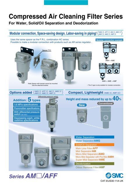
Compressed Air Cleaning Filter Series<br />
For Water, Solid/Oil Separation and Deodorization<br />
Modular connection, Space-saving design, Labor-saving in piping!<br />
<strong>AM</strong>GC, <strong>AFF</strong>C, <strong>AM</strong>C, <strong>AM</strong>DC<br />
<strong>AM</strong>HC, <strong>AM</strong>EC, <strong>AM</strong>FC<br />
Uses the same spacer as the F.R.L. combination AC series.<br />
Possible to make a modular connection with products such as AR series regulator.<br />
Modular connection example<br />
Spacer Note)<br />
<strong>AM</strong>H + <strong>AM</strong>E<br />
<strong>AM</strong>H + <strong>AM</strong>E + <strong>AM</strong>F<br />
Note) Spacer with bracket cannot be mounted.<br />
Use the attached bracket.<br />
∗ The C type is only suitable for modular connection.<br />
Options added<br />
<strong>AM</strong>GC, <strong>AFF</strong>C, <strong>AM</strong>C, <strong>AM</strong>DC<br />
<strong>AM</strong>HC, <strong>AM</strong>EC, <strong>AM</strong>FC<br />
Compact, Lightweight (<strong>AM</strong>EC, <strong>AM</strong>FC)<br />
Addition: 5 types<br />
1.6 MPa specifi<strong>cat</strong>ions<br />
Fluororubber specifi<strong>cat</strong>ions<br />
With differ<strong>en</strong>tial pressure<br />
switch (30 VDC)<br />
Degreasing wash, white<br />
vaseline specifi<strong>cat</strong>ions<br />
Differ<strong>en</strong>tial pressure switch<br />
Height and mass reduced by up to 40%<br />
New<br />
Conv<strong>en</strong>tional<br />
Water Separation<br />
Water Separator/<strong>AM</strong>G<br />
Solid/Oil Separation<br />
Main Line Filter/<strong>AFF</strong><br />
Mist Separator/<strong>AM</strong><br />
Micro Mist Separator/<strong>AM</strong>D<br />
Micro Mist Separator with Pre-filter/<strong>AM</strong>H<br />
Super Mist Separator/<strong>AM</strong>E<br />
Deodorization<br />
Odour Removal Filter/<strong>AM</strong>F<br />
Series <strong>AM</strong>/<strong>AFF</strong><br />
CAT.EUS30-11A-UK
Water droplet removal<br />
Water Separator<br />
Water droplet<br />
separation rate: 99%<br />
Model<br />
150C<br />
Flow capacity<br />
l/min (ANR)<br />
Max. flow<br />
capacity at<br />
0.7 MPa<br />
inlet pressure<br />
300<br />
Port size<br />
1/8, 1/4<br />
250C<br />
750<br />
1/4, 3/8<br />
350C<br />
1,500<br />
3/8, 1/2<br />
<strong>AM</strong>G<br />
450C<br />
2,200<br />
1/2, 3/4<br />
550C<br />
3,700<br />
3/4, 1<br />
650<br />
6,000<br />
1, 1 1/2<br />
<strong>AM</strong>G150C to 550C<br />
<strong>AM</strong>G650/850<br />
850<br />
12,000<br />
1 1/2, 2<br />
Large dust particle filtration, Oil droplet separation<br />
Main Line Filter<br />
Nominal filtration rating: 3 μm<br />
[Filtration effici<strong>en</strong>cy:<br />
99%]<br />
<strong>AFF</strong><br />
2C<br />
4C<br />
8C<br />
11C<br />
300<br />
750<br />
1,500<br />
2,200<br />
1/8, 1/4<br />
1/4, 3/8<br />
3/8, 1/2<br />
1/2, 3/4<br />
22C<br />
3,700<br />
3/4, 1<br />
37B<br />
6,000<br />
1, 1 1/2<br />
75B<br />
12,000<br />
1 1/2, 2<br />
<strong>AFF</strong>2C to 22C<br />
<strong>AFF</strong>37B/75B<br />
Dust filtration, Oil mist separation<br />
Mist Separator<br />
150C<br />
250C<br />
350C<br />
300<br />
750<br />
1,500<br />
1/8, 1/4<br />
1/4, 3/8<br />
3/8, 1/2<br />
Nominal filtration rating: 0.3 μm<br />
[Filtration effici<strong>en</strong>cy: 99.9%]<br />
Oil mist d<strong>en</strong>sity at outlet:<br />
Max. 1.0 mg/m 3 (ANR)<br />
[≈0.8 ppm]<br />
<strong>AM</strong><br />
450C<br />
550C<br />
650<br />
2,200<br />
3,700<br />
6,000<br />
1/2, 3/4<br />
3/4, 1<br />
1, 1 1/2<br />
<strong>AM</strong>150C to 550C<br />
<strong>AM</strong>650/850<br />
850<br />
12,000<br />
1 1/2, 2<br />
Dust filtration, Oil mist separation<br />
Micro Mist Separator<br />
150C<br />
200<br />
1/8, 1/4<br />
Nominal filtration rating: 0.01 μm<br />
[Filtration effici<strong>en</strong>cy: 99.9%]<br />
Oil mist d<strong>en</strong>sity at outlet:<br />
Max. 0.1 mg/m 3 (ANR)<br />
[≈0.08 ppm]<br />
<strong>AM</strong>D<br />
250C<br />
350C<br />
450C<br />
500<br />
1,000<br />
2,000<br />
1/4, 3/8<br />
3/8, 1/2<br />
1/2, 3/4<br />
550C<br />
3,700<br />
3/4, 1<br />
650<br />
6,000<br />
1, 1 1/2<br />
850<br />
12,000<br />
1 1/2, 2<br />
<strong>AM</strong>D150C to 550C <strong>AM</strong>D650 to 850<br />
Features 1
Series <strong>AM</strong>/<strong>AFF</strong><br />
Dust filtration, Oil mist separation<br />
Micro Mist Separator<br />
with Pre-filter<br />
Built-in 0.3 μm pre-filter<br />
The <strong>AM</strong> + <strong>AM</strong>D elem<strong>en</strong>t have be<strong>en</strong> integrated to<br />
achieve a space-saving design.<br />
Nominal filtration rating: 0.01 μm<br />
[Filtration effici<strong>en</strong>cy: 99.9%]<br />
Oil mist d<strong>en</strong>sity at outlet:<br />
Max. 0.1 mg/m 3 (ANR)<br />
[≈0.08 ppm]<br />
Model<br />
150C<br />
250C<br />
350C<br />
Flow capacity<br />
l/min (ANR)<br />
Max. flow<br />
capacity at<br />
0.7 MPa<br />
inlet pressure<br />
200<br />
500<br />
1,000<br />
Port size<br />
1/8, 1/4<br />
1/4, 3/8<br />
3/8, 1/2<br />
<strong>AM</strong>H<br />
450C<br />
2,000<br />
1/2, 3/4<br />
550C<br />
3,700<br />
3/4, 1<br />
650<br />
6,000<br />
1, 1 1/2<br />
<strong>AM</strong>H150C to 550C<br />
<strong>AM</strong>H650/850<br />
850<br />
12,000<br />
1 1/2, 2<br />
Dust filtration, Oil mist adsorption<br />
150C<br />
200<br />
1/8, 1/4<br />
Super Mist Separator<br />
Colour change indi<strong>cat</strong>es wh<strong>en</strong> elem<strong>en</strong>t is saturated.<br />
Nominal filtration rating: 0.01 μm<br />
[Filtration effici<strong>en</strong>cy: 99.9%]<br />
Oil mist d<strong>en</strong>sity at outlet:<br />
Max. 0.01 mg/m 3 (ANR)<br />
[≈0.008 ppm]<br />
Cleanliness at outlet:<br />
Not more than 35<br />
particles of size<br />
0.3 μm or larger/10 l<br />
(100 particles or less/ft 3 ) <strong>AM</strong>E150C to 550C <strong>AM</strong>E650/850<br />
Deodorization<br />
Odour Removal Filter<br />
Nominal filtration rating: 0.01 μm<br />
[Filtration effici<strong>en</strong>cy: 99.9%]<br />
Oil mist d<strong>en</strong>sity at outlet:<br />
Max. 0.004 mg/m 3 (ANR)<br />
[≈0.0032 ppm]<br />
<strong>AM</strong>E<br />
<strong>AM</strong>F<br />
250C<br />
350C<br />
450C<br />
550C<br />
650<br />
850<br />
150C<br />
250C<br />
350C<br />
450C<br />
500<br />
1,000<br />
2,000<br />
3,700<br />
6,000<br />
12,000<br />
200<br />
500<br />
1,000<br />
2,000<br />
1/4, 3/8<br />
3/8, 1/2<br />
1/2, 3/4<br />
3/4, 1<br />
1, 1 1/2<br />
1 1/2, 2<br />
1/8, 1/4<br />
1/4, 3/8<br />
3/8, 1/2<br />
1/2, 3/4<br />
550C<br />
3,700<br />
3/4, 1<br />
650<br />
6,000<br />
1, 1 1/2<br />
850<br />
12,000<br />
1 1/2, 2<br />
<strong>AM</strong>F150C to 550C <strong>AM</strong>F650 to 850<br />
Features 2
Compressed Air Cleaning Filter Series<br />
Series <strong>AM</strong>/<strong>AFF</strong><br />
Series<br />
Water<br />
removal<br />
rate<br />
Nominal<br />
filtration rating<br />
Oil mist d<strong>en</strong>sity<br />
at outlet<br />
Smell<br />
Page<br />
Water Separator<br />
Water Separator<br />
Eliminates water droplets in the<br />
compressed air.<br />
Series<br />
<strong>AM</strong>G<br />
99%<br />
—<br />
—<br />
—<br />
P.2<br />
Main Line Filter<br />
Eliminates impurities such as<br />
oil and foreign matter, etc. in<br />
compressed air.<br />
Series<br />
<strong>AFF</strong><br />
3 μm<br />
(Filtration<br />
effici<strong>en</strong>cy:<br />
99%)<br />
—<br />
P.10<br />
Deodorizer Solid/Oil Separator<br />
Mist Separator<br />
Eliminates oil mist in<br />
compressed air or rust sized<br />
0.3 μm or more, and foreign<br />
matter such as carbon.<br />
Micro Mist Separator<br />
Eliminates foreign matter<br />
sized 0.01 μm or more, or oil<br />
particles in an aerosol state.<br />
Micro Mist Separator with<br />
Pre-filter<br />
Oil separator, which incorporates<br />
pre-filter (equival<strong>en</strong>t to the <strong>AM</strong><br />
series) into micro mist separator.<br />
Super Mist Separator<br />
Captures foreign matter sized<br />
0.01 μm or more and adsorbs<br />
oil particles in an aerosol state.<br />
Odour Removal Filter<br />
Eliminates odour from<br />
compressed air.<br />
Series<br />
<strong>AM</strong><br />
Series<br />
<strong>AM</strong>D<br />
Series<br />
<strong>AM</strong>H<br />
Series<br />
<strong>AM</strong>E<br />
Series<br />
<strong>AM</strong>F<br />
—<br />
0.3 μm<br />
(Filtration<br />
effici<strong>en</strong>cy:<br />
99.9%)<br />
0.01 μm<br />
(Filtration<br />
effici<strong>en</strong>cy:<br />
99.9%)<br />
0.3 + 0.01 μm<br />
(Filtration<br />
effici<strong>en</strong>cy:<br />
99.9%)<br />
0.01 μm<br />
(Filtration<br />
effici<strong>en</strong>cy:<br />
99.9%)<br />
1 mg/m 3 (ANR)<br />
(≈0.8 ppm)<br />
(after oil saturation)<br />
0.1 mg/m 3 (ANR)<br />
(≈0.08 ppm)<br />
(after oil saturation)<br />
0.01 mg/m 3 (ANR)<br />
(≈0.008 ppm)<br />
0.004 mg/m 3 (ANR)<br />
(≈0.0032 ppm)<br />
—<br />
Reduces<br />
oil smell.<br />
Deodorizes<br />
oil smell.<br />
P.18<br />
P.26<br />
P.34<br />
P.42<br />
P.50<br />
Modular Connection Examples<br />
P.58<br />
How to Order Bowl Assembly<br />
P.59<br />
Options<br />
Seal material: Fluororubber IN-OUT reversal direction Degreasing wash,<br />
For medium air pressure Drain guide 1/4 female threaded<br />
white vaseline<br />
With elem<strong>en</strong>t service indi<strong>cat</strong>or<br />
With differ<strong>en</strong>tial pressure switch (with indi<strong>cat</strong>or)<br />
<br />
(125 VAC, 30 VDC)<br />
With differ<strong>en</strong>tial pressure switch (with indi<strong>cat</strong>or)<br />
(30 VDC)<br />
Refer to<br />
“How to<br />
Order” of<br />
respective<br />
models.<br />
Made to Order<br />
With differ<strong>en</strong>tial pressure gauge<br />
Possible to control product , s service life<br />
by monitoring the clogged elem<strong>en</strong>t.<br />
Auto drain type, drain guide<br />
specifi<strong>cat</strong>ions<br />
Drain piping is possible by auto drain type.<br />
White vaseline specifi<strong>cat</strong>ions ∗<br />
Using white vaseline for lubricant.<br />
P.63<br />
∗ Applicable only to the <strong>AFF</strong>37B, 75B, <strong>AM</strong>650 and 850.<br />
Special Specifi<strong>cat</strong>ions<br />
Clean Series<br />
Usable inside a clean room.<br />
Copper-free, Fluorine-free<br />
Eliminates the effects on a colour CRT by copper ion or<br />
fluoric resin, etc.<br />
P.63<br />
Related Products<br />
Auto Drain Valve, Motor Operated Auto Drain, Heavy Duty Auto Drain, Differ<strong>en</strong>tial Pressure Gauge<br />
P.67<br />
Specific Product Precautions<br />
Back page 3<br />
1<br />
Discontinued Model and Equival<strong>en</strong>t Model<br />
Back page 7
Water Separator<br />
Series <strong>AM</strong>G<br />
Can remove water droplets in compressed<br />
air. Use this product in cases<br />
where “water must be avoided,<br />
but not so dry as wh<strong>en</strong> an air dryer is<br />
used”.<br />
Through the adoption of an elem<strong>en</strong>t<br />
that is exclusively used for removing<br />
water droplets and the ample housing<br />
interior space, a 99%∗ water removal<br />
rate∗∗ has be<strong>en</strong> achieved.<br />
Caution<br />
Water separator can remove water droplets, but<br />
it cannot remove moisture.<br />
∗ Condition of inlet air<br />
Pressure: 0.7 MPa<br />
Temperature: 25°C<br />
Relative humidity: 100%<br />
Liquid water cont<strong>en</strong>t (Water droplet<br />
cont<strong>en</strong>t): 15 g/m 3 (ANR)<br />
Compressed air flow: Rated flow of each<br />
model<br />
∗∗ Water removal rate (%) =<br />
Removed water (Water droplet) (g)<br />
x 100<br />
Inflowed water (Water droplet) (g)<br />
Modular connection is possible<br />
with <strong>AM</strong>G150C to 550C.<br />
(For details, refer to page 58.)<br />
Model<br />
Model <strong>AM</strong>G150C <strong>AM</strong>G250C <strong>AM</strong>G350C <strong>AM</strong>G450C <strong>AM</strong>G550C <strong>AM</strong>G650 <strong>AM</strong>G850<br />
Note)<br />
Rated flow (l/min (ANR))<br />
300 750 1500 2200 3700 6000 12000<br />
Port size<br />
Mass (kg)<br />
1 8, 1 4<br />
0.38<br />
1 4, 3 8<br />
0.55<br />
3 8, 1 2<br />
0.9<br />
1 2, 3 4<br />
1.4<br />
3 4, 1<br />
2.1<br />
1, 1 1 2<br />
4.2<br />
11 2, 2<br />
10.5<br />
Note) Max. flow at 0.7 MPa.<br />
Max. flow varies dep<strong>en</strong>ding on the operating pressure. Refer to “Flow Characteristics” (page 5)<br />
and “Maximum Air flow” (page 6).<br />
Specifi<strong>cat</strong>ions<br />
Fluid<br />
Compressed air<br />
Max. operating pressure<br />
1.0 MPa<br />
Min. operating pressure ∗<br />
0.05 MPa<br />
Proof pressure<br />
1.5 MPa<br />
Ambi<strong>en</strong>t and fluid temperature<br />
5 to 60°C<br />
Water removal rate<br />
99%<br />
Elem<strong>en</strong>t life<br />
2 years or wh<strong>en</strong> pressure drop reached 0.1 MPa<br />
∗ With auto drain: 0.1 MPa (N.O. type) or 0.15 MPa (N.C. type)<br />
Accessory<br />
Applicable model<br />
Bracket assembly<br />
(with 2 mounting screws)<br />
Caution<br />
<strong>AM</strong>G150C <strong>AM</strong>G250C <strong>AM</strong>G350C <strong>AM</strong>G450C <strong>AM</strong>G550C <strong>AM</strong>G650<br />
<strong>AM</strong>G850<br />
<strong>AM</strong>-BM101 <strong>AM</strong>-BM102 <strong>AM</strong>-BM103 <strong>AM</strong>-BM104 <strong>AM</strong>-BM105 BM56 BM57<br />
Be sure to read this before handling.<br />
Refer to back pages 1 and 2 for Safety Instructions, “Precautions for<br />
Handling Pneumatic Devices” (M-03-E3A) for Common Precautions,<br />
and back pages 3 through to 7 for Specific Product Precautions.<br />
<strong>AM</strong>G150C to 550C<br />
Symbol<br />
<strong>AM</strong>G<br />
<strong>AM</strong>G650/850<br />
<strong>AM</strong>G<br />
(For drain cock)<br />
(For auto drain)<br />
Made to Order<br />
(For details, refer to page 63.)<br />
2
Series <strong>AM</strong>G<br />
How to Order<br />
<strong>AM</strong>G150C to 550C<br />
<strong>AM</strong>G 550C 10<br />
Body size<br />
150C<br />
250C<br />
350C<br />
450C<br />
550C<br />
Made to Order<br />
(“How to Order” and the applicable models are differ<strong>en</strong>t from those<br />
shown on this page. Be sure to refer to “Made to Order”.)<br />
Symbol<br />
—<br />
X26<br />
Description<br />
—<br />
N.C., N.O. auto drain, drain piping type<br />
Page for details<br />
—<br />
P.65<br />
Symbol<br />
01<br />
02<br />
03<br />
04<br />
06<br />
10<br />
Thread type<br />
Symbol Type<br />
— Rc<br />
F G ∗1<br />
N NPT<br />
∗1 Conforms to<br />
ISO1179-1.<br />
Port size<br />
Applicable body size<br />
Size 150C 250C 350C 450C 550C<br />
1/8<br />
1/4<br />
3/8<br />
1/2<br />
3/4<br />
1<br />
Symbol<br />
—<br />
B<br />
Accessory<br />
Description<br />
—<br />
Bracket ∗2<br />
∗2 Bracket is included,<br />
(but not assembled).<br />
Option ∗3<br />
Symbol<br />
Description<br />
—<br />
—<br />
F Rubber material: Fluororubber<br />
H For medium air pressure (1.6 MPa)<br />
J Drain guide 1/4 female threaded ∗4<br />
R IN-OUT reversal direction<br />
V Degreasing wash, ∗5 white vaseline<br />
∗4 Drain piping and piping for a stop valve such<br />
as ball valve are required.<br />
∗5 Only body/housing is degreasing washed.<br />
Auto drain ∗3<br />
Symbol<br />
Description<br />
— Drain cock (Without auto drain)<br />
C N.C. auto drain<br />
D N.O. auto drain<br />
∗3 Refer to the table below for the combination betwe<strong>en</strong> the draining<br />
specifi<strong>cat</strong>ion and option. (Only one draining specifi<strong>cat</strong>ion is selectable).<br />
Auto Drain Specifi<strong>cat</strong>ions/Option Combinations<br />
: All draining specifi<strong>cat</strong>ions are available (including drain guide, J type).<br />
: N.C. auto drain (C type) is not available.<br />
: N.C. auto drain (C type) and N.O. auto drain (D type) are not available.<br />
—<br />
—<br />
F<br />
H<br />
R<br />
V<br />
: Not available<br />
F H R V<br />
Options<br />
Symbol F: Rubber material: Fluororubber<br />
Fluororubber is used for the parts<br />
such as O-ring and gasket.<br />
Symbol H: For medium air pressure<br />
(1.6 MPa)<br />
Can be used up to 1.6 MPa at<br />
maximum.<br />
Symbol J: Drain guide 1/4 female threaded<br />
Can be pipied to the<br />
drain exhaust port.<br />
1/4 female threaded<br />
Symbol R: IN-OUT reversal direction<br />
Air flow in the separator is changed to<br />
right to left.<br />
(Air flow direction of the standard: Left<br />
to right.)<br />
Symbol V: Degreasing wash,<br />
white vaseline<br />
Body/housing is degreasing washed. The<br />
lubri<strong>cat</strong>ion grease for O-ring and gasket is<br />
changed to white vaseline.<br />
3
<strong>AM</strong>G650/850<br />
<strong>AM</strong>G 650 10<br />
Body size<br />
650<br />
850<br />
Symbol<br />
10<br />
14<br />
20<br />
Thread type<br />
Symbol Type<br />
— Rc<br />
F G<br />
N NPT<br />
Size<br />
1<br />
1 1 2<br />
2<br />
Port size<br />
Applicable body size<br />
650 850<br />
Symbol<br />
—<br />
B<br />
Accessory<br />
Description<br />
—<br />
Bracket ∗1<br />
∗1 Bracket is included,<br />
(but not assembled).<br />
How to Order<br />
Water Separator Series <strong>AM</strong>G<br />
Made to Order<br />
(“How to Order” and the applicable models are differ<strong>en</strong>t from those<br />
shown on this page. Be sure to refer to “Made to Order”.)<br />
Symbol<br />
Description<br />
Page for details<br />
—<br />
—<br />
—<br />
X26 N.C., N.O. auto drain, drain piping type P.65<br />
X12 White vaseline<br />
P.65<br />
Option ∗2<br />
Symbol<br />
Description<br />
—<br />
—<br />
J Drain guide 1 4 female threaded ∗4<br />
R IN-OUT reversal direction<br />
∗4 Drain piping and piping for a stop valve such<br />
as ball valve are required.<br />
Note) Elem<strong>en</strong>t service indi<strong>cat</strong>or (symbol: T) is not<br />
available as an option because water<br />
deposits inside the indi<strong>cat</strong>or could lead to<br />
malfunctions.<br />
Auto drain ∗2<br />
Symbol<br />
Description<br />
— Drain cock (Without auto drain) ∗3<br />
D N.O. auto drain<br />
∗2 Refer to “Auto Drain Specifi<strong>cat</strong>ions/Option<br />
Combinations”.<br />
∗3 Body size 850 is equipped with a ball valve<br />
(Rc3/8 female threaded). Mount a piping<br />
adapter IDF-AP609 (page 58) to the ball valve if<br />
NPT3/8 female threaded is required.<br />
Note) Refer to “How to Order Bowl Assembly” on page 63.<br />
Auto Drain Specifi<strong>cat</strong>ions/Option Combinations<br />
Auto drain specifi<strong>cat</strong>ions/Option<br />
Auto drain specifi<strong>cat</strong>ions<br />
Option<br />
N.O. auto drain<br />
Drain guide 1 4<br />
IN-OUT reversal<br />
direction<br />
D<br />
J<br />
R<br />
Auto drain specifi<strong>cat</strong>ions Option<br />
D J R<br />
: Available : Not available<br />
Applicable model<br />
<strong>AM</strong>G650 <strong>AM</strong>G850<br />
4
Series <strong>AM</strong>G<br />
Flow Characteristics<br />
Note) Compressed air over max. flow line in the table below may not meet the specifi<strong>cat</strong>ions of the product.<br />
It may cause damage to the elem<strong>en</strong>t.<br />
<strong>AM</strong>G150C <strong>AM</strong>G450C <strong>AM</strong>G850<br />
Max. flow line<br />
Pressure drop (MPa)<br />
Max. flow line<br />
Pressure drop (MPa)<br />
Pressure drop (MPa)<br />
Max. flow line<br />
Air flow rate (l/min (ANR))<br />
Air flow rate (l/min (ANR))<br />
Air flow rate (m 3 /min (ANR))<br />
<strong>AM</strong>G250C<br />
<strong>AM</strong>G550C<br />
Max. flow line<br />
Pressure drop (MPa)<br />
Max. flow line<br />
Pressure drop (MPa)<br />
Air flow rate (l/min (ANR))<br />
Air flow rate (l/min (ANR))<br />
<strong>AM</strong>G350C<br />
Max. flow line<br />
<strong>AM</strong>G650<br />
Pressure drop (MPa)<br />
Pressure drop (MPa)<br />
Max. flow line<br />
Air flow rate (l/min (ANR))<br />
Air flow rate (l/min (ANR))<br />
5
Water Separator Series <strong>AM</strong>G<br />
Construction<br />
<strong>AM</strong>G150C to 550C, <strong>AM</strong>G650<br />
q<br />
<strong>AM</strong>G850<br />
IN<br />
OUT<br />
IN<br />
OUT<br />
r<br />
w<br />
e<br />
Compon<strong>en</strong>t Parts<br />
No.<br />
1<br />
2<br />
3<br />
Replacem<strong>en</strong>t Parts<br />
No.<br />
4<br />
Description Material Note<br />
Body<br />
Aluminum die-casted Chrome treated<br />
Aluminum die-casted ∗ Epoxy coating on<br />
Housing<br />
inner surface<br />
Sight glass Tempered glass<br />
—<br />
∗ The <strong>AM</strong>G850 is aluminum casted.<br />
Description Material<br />
Elem<strong>en</strong>t<br />
assembly<br />
Resin,<br />
others<br />
Applicable<br />
model<br />
Except option F<br />
For option F<br />
<strong>AM</strong>G150C<br />
<strong>AM</strong>G-EL150<br />
<strong>AM</strong>G-EL150-F<br />
<strong>AM</strong>G250C<br />
<strong>AM</strong>G-EL250<br />
<strong>AM</strong>G-EL250-F<br />
<strong>AM</strong>G350C<br />
<strong>AM</strong>G-EL350<br />
<strong>AM</strong>G-EL350-F<br />
Note) Refer to “How to Order Bowl Assembly” on page 59.<br />
Note) Sight glass is indi<strong>cat</strong>ed in the figure for easy understanding<br />
of compon<strong>en</strong>t parts. However, it differs from the actual<br />
construction. Refer to dim<strong>en</strong>sions on pages 7 through to 9<br />
for details.<br />
Model<br />
<strong>AM</strong>G450C<br />
<strong>AM</strong>G-EL450<br />
<strong>AM</strong>G-EL450-F<br />
∗ Elem<strong>en</strong>t assembly: With gasket (1 pc.) and O-ring (1 pc.)<br />
∗ Refer to back page 6 for replacem<strong>en</strong>t of auto drain.<br />
∗ Elem<strong>en</strong>t assemblies for Made to Order (X12, X20, X26) are same as those for standard (see the above table).<br />
<strong>AM</strong>G550C<br />
<strong>AM</strong>G-EL550<br />
<strong>AM</strong>G-EL550-F<br />
<strong>AM</strong>G650<br />
<strong>AM</strong>G-EL650<br />
—<br />
<strong>AM</strong>G850<br />
<strong>AM</strong>G-EL850<br />
—<br />
Maximum Air Flow<br />
Max. air flow rate (m 3 /min (ANR))<br />
Model Selection<br />
Select a model in accordance with the following procedure taking the<br />
inlet pressure and the max. air flow rate into consideration.<br />
(Example) Inlet pressure: 0.6 MPa<br />
Max. air flow rate: 5 m 3 /min (ANR)<br />
1. Obtain the intersecting point A of inlet pressure and max. air flow<br />
rate in the graph.<br />
2. The <strong>AM</strong>G650 is obtained wh<strong>en</strong> the max. flow line is above the interecting<br />
point A in the graph.<br />
Note) Make sure to select a model that has the max. flow line above<br />
the obtained intersecting point. With a model that has the max.<br />
flow line below the obtained intersecting point, the flow rate will<br />
be exceeded, thus leading to a problem such as being unable to<br />
satisfy the specifi<strong>cat</strong>ions.<br />
Inlet pressure (MPa)<br />
6
Series <strong>AM</strong>G<br />
Dim<strong>en</strong>sions<br />
<strong>AM</strong>G150C to 550C<br />
P<br />
Q<br />
Auto drain<br />
C: With auto drain (N.C.)<br />
D: With auto drain (N.O.)<br />
F<br />
O<br />
D<br />
I<br />
K<br />
T<br />
L<br />
M<br />
Bracket<br />
(Accessory)<br />
U<br />
øV<br />
H<br />
C<br />
IN<br />
J<br />
R<br />
S<br />
Drain cock<br />
Gray: N.C.<br />
Black: N.O.<br />
34<br />
ø10 one-touch fitting<br />
Combination of D: With auto drain (N.O.)<br />
and H: For medium air pressure<br />
N<br />
A<br />
E B<br />
OUT<br />
20<br />
1/4 female threaded<br />
Option<br />
J: Drain guide 1/4 female threaded<br />
M5<br />
G<br />
Maint<strong>en</strong>ance<br />
space<br />
Drain<br />
1/4 female threaded<br />
20<br />
Model<br />
<strong>AM</strong>G150C<br />
<strong>AM</strong>G250C<br />
<strong>AM</strong>G350C<br />
<strong>AM</strong>G450C<br />
<strong>AM</strong>G550C<br />
Port size<br />
1/8, 1/4<br />
1/4, 3/8<br />
3/8, 1/2<br />
1/2, 3/4<br />
3/4, 1<br />
A<br />
158<br />
172<br />
204<br />
225<br />
259<br />
B<br />
10<br />
14<br />
18<br />
20<br />
24<br />
C<br />
99<br />
113<br />
145<br />
166<br />
200<br />
D<br />
63<br />
76<br />
90<br />
106<br />
122<br />
E<br />
20<br />
20<br />
20<br />
20<br />
20<br />
F<br />
63<br />
76<br />
90<br />
106<br />
122<br />
G<br />
10<br />
10<br />
10<br />
10<br />
15<br />
H<br />
173<br />
190<br />
222<br />
246<br />
278<br />
I<br />
56<br />
66<br />
80<br />
90<br />
100<br />
J<br />
20<br />
24<br />
28<br />
31<br />
33<br />
K<br />
5<br />
8<br />
8<br />
10<br />
10<br />
T<br />
6<br />
6<br />
7<br />
9<br />
9<br />
Bracket related dim<strong>en</strong>sions<br />
U L M V N<br />
6 12 6 10 35<br />
6<br />
7<br />
9<br />
9<br />
12<br />
14<br />
18<br />
18<br />
6<br />
7<br />
9<br />
9<br />
10<br />
12<br />
15<br />
15<br />
40<br />
50<br />
55<br />
65<br />
O<br />
54<br />
66<br />
80<br />
88<br />
102<br />
P<br />
70<br />
80<br />
95<br />
111<br />
126<br />
Q<br />
26<br />
28<br />
34<br />
50<br />
60<br />
R<br />
4.5<br />
5<br />
5<br />
9<br />
10<br />
(mm)<br />
S<br />
1.6<br />
2<br />
2.3<br />
3.2<br />
3.2<br />
7
Water Separator Series <strong>AM</strong>G<br />
Dim<strong>en</strong>sions<br />
<strong>AM</strong>G650<br />
Auto drain<br />
D: With auto drain (N.O.)<br />
180<br />
76<br />
12<br />
4.5<br />
Drain cock: Black<br />
85<br />
20<br />
311<br />
32<br />
160<br />
136<br />
Option<br />
J: Drain guide 1/4 female threaded<br />
160<br />
15<br />
20<br />
11<br />
150<br />
Bracket<br />
(Accessory)<br />
253<br />
334<br />
40<br />
IN<br />
OUT<br />
M5<br />
10<br />
Drain<br />
Maint<strong>en</strong>ance<br />
space<br />
34<br />
ø10 one-touch fitting<br />
20<br />
1/4 female threaded<br />
8
Series <strong>AM</strong>G<br />
Dim<strong>en</strong>sions<br />
<strong>AM</strong>G850<br />
Auto drain<br />
220<br />
110<br />
D: With auto drain (N.O.)<br />
for <strong>AM</strong>G850<br />
120<br />
58<br />
461<br />
42<br />
220<br />
184<br />
18<br />
15<br />
6<br />
24<br />
13<br />
220<br />
180<br />
464<br />
348<br />
30<br />
23<br />
3/8 female threaded<br />
Bracket<br />
(Accessory)<br />
IN<br />
OUT<br />
10<br />
Maint<strong>en</strong>ance<br />
space<br />
Drain<br />
Rc 3/8 female threaded<br />
9
Main Line Filter<br />
Series <strong>AFF</strong><br />
Can remove impurities such as oil,<br />
water and foreign matter in compressed<br />
air and can improve the function<br />
of a dryer in the downstream, ext<strong>en</strong>d<br />
the life of precision filter, and prev<strong>en</strong>t<br />
trouble with the equipm<strong>en</strong>t.<br />
Modular connection is possible<br />
with <strong>AFF</strong>2C to 22C.<br />
(For details, refer to page 58.)<br />
Model<br />
Model <strong>AFF</strong>2C <strong>AFF</strong>4C <strong>AFF</strong>8C <strong>AFF</strong>11C <strong>AFF</strong>22C <strong>AFF</strong>37B <strong>AFF</strong>75B<br />
Rated flow Note)<br />
300<br />
6000 12000<br />
(l/min (ANR))<br />
Port size<br />
Mass (kg)<br />
750 1500 2200 3700<br />
1 8, 1 4 1 4, 3 8 3 8, 1 2 1 2, 3 4<br />
0.38<br />
0.55<br />
0.9<br />
1.4<br />
3 4, 1 1, 1 1 2 1 1 2, 2<br />
Note) Max. flow at 0.7 MPa.<br />
Max. flow varies dep<strong>en</strong>ding on the operating pressure.<br />
Refer to “Flow Characteristics” (page 13) and “Maximum Air Flow” below.<br />
2.1<br />
4.2<br />
10.5<br />
Specifi<strong>cat</strong>ions<br />
Fluid<br />
Compressed air<br />
Max. operating pressure<br />
1.0 MPa<br />
Min. operating pressure ∗<br />
0.05 MPa<br />
Proof pressure<br />
1.5 MPa<br />
Ambi<strong>en</strong>t and fluid temperature<br />
5 to 60°C<br />
Nominal filtration rating<br />
3 μm (Filtration effici<strong>en</strong>cy: 99%)<br />
Elem<strong>en</strong>t life<br />
2 years (1 year for A type) or wh<strong>en</strong> pressure drop reached 0.1 MPa<br />
∗ With auto drain: 0.1 MPa (N.O. type) or 0.15 MPa (N.C. type)<br />
<strong>AFF</strong>2C to 22C<br />
Accessory/For <strong>AFF</strong>2C to 22C, <strong>AFF</strong>37B/75B<br />
Applicable model <strong>AFF</strong>2C <strong>AFF</strong>4C <strong>AFF</strong>8C <strong>AFF</strong>11C <strong>AFF</strong>22C <strong>AFF</strong>37B <strong>AFF</strong>75B<br />
Bracket assembly<br />
(with 2 mounting screws)<br />
<strong>AM</strong>-BM101 <strong>AM</strong>-BM102 <strong>AM</strong>-BM103 <strong>AM</strong>-BM104 <strong>AM</strong>-BM105 BM56 BM57<br />
Symbol<br />
<strong>AFF</strong><br />
(For drain cock)<br />
<strong>AFF</strong>37B/75B<br />
<strong>AFF</strong><br />
(For auto drain)<br />
Made to Order<br />
(For details, refer to page 63.)<br />
Caution<br />
Be sure to read this before<br />
handling.<br />
Refer to back pages 1 and 2<br />
for Safety Instructions, “Precautions<br />
for Handling Pneumatic<br />
Devices” (M-03-E3A) for<br />
Common Precautions, and<br />
back pages 3 through to 7 for<br />
Specific Product Precautions.<br />
Model Selection<br />
Select a model in accordance with the<br />
following procedure taking the inlet pressure<br />
and the max. air flow rate into consideration.<br />
(Example) Inlet pressure: 0.6 MPa<br />
Max. air flow rate: 5 m 3 /min<br />
(ANR)<br />
1. Obtain the intersecting point A of inlet<br />
pressure and max. air flow rate in the<br />
graph.<br />
2. The <strong>AFF</strong>37B is obtained wh<strong>en</strong> the max.<br />
flow line is above the intersecting point A<br />
in the graph.<br />
Note) Make sure to select a model that<br />
has the max. flow line above the<br />
obtained intersecting point. With a<br />
model that has the max. flow line<br />
below the obtained intersecting<br />
point, the flow rate will be exceeded,<br />
thus leading to a problem<br />
such as being unable to satisfy the<br />
specifi<strong>cat</strong>ions.<br />
Maximum Air Flow<br />
Max. air flow rate (m 3 /min (ANR))<br />
Max. flow line<br />
Inlet pressure (MPa)<br />
10
0.1<br />
.05<br />
0.15<br />
0.2<br />
MPa<br />
SMC<br />
Series <strong>AFF</strong><br />
How to Order<br />
<strong>AFF</strong>2C to 22C<br />
<strong>AFF</strong> 22C 10<br />
Body size<br />
Applicable compressor<br />
Symbol<br />
output (guide)<br />
2C<br />
2.2 kW<br />
4C<br />
3.7 kW<br />
8C<br />
7.5 kW<br />
11C<br />
11 kW<br />
22C<br />
22 kW<br />
Symbol<br />
01<br />
02<br />
03<br />
04<br />
06<br />
10<br />
Size<br />
1/8<br />
1/4<br />
3/8<br />
1/2<br />
3/4<br />
1<br />
Options<br />
Port size<br />
Applicable body size<br />
2C 4C 8C 11C 22C<br />
Thread type<br />
Symbol Type<br />
— Rc<br />
F G ∗1<br />
N NPT<br />
∗1 Conforms to<br />
ISO1179-1.<br />
Symbol<br />
—<br />
B<br />
Accessory<br />
Description<br />
—<br />
Bracket ∗2<br />
∗2 Bracket is included,<br />
(but not assembled).<br />
Auto Drain Specifi<strong>cat</strong>ions/Option Combinations<br />
: All draining specifi<strong>cat</strong>ions are available (including drain guide, J type).<br />
: N.C. auto drain (C type) is not available.<br />
: N.C. auto drain (C type) and N.O. auto drain (D type) are not available.<br />
—<br />
F<br />
H<br />
R<br />
U<br />
T<br />
V<br />
— F H R U T V<br />
Note<br />
Note<br />
Note) one of them selectable<br />
Note<br />
Note<br />
: Not available<br />
Made to Order<br />
(“How to Order” and the applicable models are differ<strong>en</strong>t from those shown<br />
on this page. Be sure to refer to “Made to Order”.)<br />
Symbol<br />
—<br />
X6<br />
X26<br />
Description<br />
—<br />
With differ<strong>en</strong>tial pressure gauge (GD40-2-01)<br />
N.C., N.O. auto drain, drain piping type<br />
Option ∗3<br />
Symbol<br />
Description<br />
—<br />
—<br />
F Rubber material: Fluororubber<br />
H For medium air pressure (1.6 MPa)<br />
J Drain guide 1/4 female threaded ∗4<br />
R IN-OUT reversal direction<br />
U With differ<strong>en</strong>tial pressure switch (30 V) ∗5<br />
T With elem<strong>en</strong>t service indi<strong>cat</strong>or<br />
V Degreasing wash, ∗6 white vaseline<br />
Auto drain ∗3<br />
Symbol<br />
Description<br />
— Drain cock (Without auto-drain)<br />
C N.C. auto drain<br />
D N.O. auto drain<br />
∗3 Refer to the table below for the combination betwe<strong>en</strong> the draining<br />
specifi<strong>cat</strong>ion and option. (Only one draining specifi<strong>cat</strong>ion is selectable).<br />
Page for details<br />
—<br />
P.64<br />
P.65<br />
∗4 Drain piping and piping for a stop valve such as ball valve are required.<br />
∗5 Differ<strong>en</strong>tial pressure gauge is included, (but not assembled).<br />
∗6 Only body/housing is degreasing washed.<br />
Symbol F: Rubber material: Fluororubber<br />
Fluororubber is used for the parts<br />
such as O-ring and gasket.<br />
Symbol H: For medium air pressure<br />
(1.6 MPa)<br />
Can be used up to 1.6 MPa at<br />
maximum.<br />
Symbol J: Drain guide 1/4 female threaded<br />
1/4 female thread<br />
Can be pipied to the<br />
drain exhaust port.<br />
Symbol R: IN-OUT reversal direction<br />
Air flow in the separator is changed to<br />
right to left.<br />
(Air flow direction of the standard: Left<br />
to right.)<br />
Symbol T: With elem<strong>en</strong>t service indi<strong>cat</strong>or<br />
Symbol U: With differ<strong>en</strong>tial pressure<br />
switch (with indi<strong>cat</strong>or)<br />
Saturation of the<br />
separator can be<br />
observed visually or by<br />
an electrical signal.<br />
(Elem<strong>en</strong>t life check)<br />
Pressure<br />
drop<br />
0.1 MPa<br />
Saturation of the<br />
separator can be<br />
observed visually.<br />
(Elem<strong>en</strong>t life check)<br />
Max. contact capacity: 10 W DC<br />
Rated contact voltage (max. operating<br />
curr<strong>en</strong>t): 30 V DC (0.33 A)<br />
Symbol V: Degreasing wash,<br />
white vaseline<br />
Body/housing is degreasing washed. The<br />
lubri<strong>cat</strong>ion grease for O-ring and gasket is<br />
changed to white vaseline.<br />
Reed switch<br />
11
Main Line Filter Series <strong>AFF</strong><br />
How to Order<br />
<strong>AFF</strong>37B/75B<br />
<strong>AFF</strong> 37B 10<br />
Symbol<br />
37B<br />
75B<br />
Body size<br />
Applicable compressor<br />
output (guide)<br />
37 kW<br />
75 kW<br />
Thread type<br />
Symbol Type<br />
— Rc<br />
F G<br />
N NPT<br />
Made to Order<br />
(“How to Order” and the applicable models are differ<strong>en</strong>t from those shown on this<br />
page. Be sure to refer to “Made to Order”.)<br />
Symbol<br />
Description<br />
—<br />
—<br />
X6 With differ<strong>en</strong>tial pressure gauge (GD40-2-01)<br />
X26 N.C., N.O. auto drain, drain piping type<br />
X12 White vaseline specifi<strong>cat</strong>ions<br />
Page for details<br />
—<br />
P.64<br />
P.65<br />
P.65<br />
Symbol<br />
10<br />
14<br />
20<br />
Size<br />
1<br />
1 1 2<br />
2<br />
Port size<br />
Applicable body size<br />
37B 75B<br />
Symbol<br />
—<br />
B<br />
Accessory<br />
Description<br />
—<br />
Bracket ∗1<br />
∗1 Bracket is included,<br />
(but not assembled).<br />
Option ∗2<br />
Symbol<br />
Description<br />
—<br />
—<br />
J Drain guide 1 4 female threaded ∗4<br />
R IN-OUT reversal direction<br />
T With elem<strong>en</strong>t service indi<strong>cat</strong>or<br />
∗4 Drain piping and piping for a stop valve<br />
such as ball valve are required.<br />
Auto drain ∗2<br />
Symbol<br />
Description<br />
— Drain cock (Without auto drain) ∗3<br />
D N.O. auto drain<br />
∗2 Refer to “Auto Drain Specifi<strong>cat</strong>ions/Option<br />
Combinations”.<br />
∗3 Body size 75B is equipped with a ball valve<br />
(Rc3/8 female threaded). Mount a piping<br />
adapter IDF-AP609 (page 58) to the ball valve<br />
if NPT3/8 female threaded is required.<br />
Note) Refer to “How to Order Bowl Assembly” on page 59.<br />
Auto Drain Specifi<strong>cat</strong>ions/Option Combinations<br />
Auto drain specifi<strong>cat</strong>ions/Option<br />
Auto drain specifi<strong>cat</strong>ions N.O. auto drain<br />
Drain guide 1 4<br />
Option IN-OUT reversal direction<br />
With elem<strong>en</strong>t service indi<strong>cat</strong>or<br />
D<br />
J<br />
R<br />
T<br />
Auto drain specifi<strong>cat</strong>ions Option<br />
D J R T<br />
: Available : Not available<br />
Applicable model<br />
<strong>AFF</strong>37B <strong>AFF</strong>75B<br />
12
Series <strong>AFF</strong><br />
Flow Characteristics/Select the model taking the max. flow capacity into consideration. (Elem<strong>en</strong>t oil saturation)<br />
Note) Compressed air over max. flow line in the table below may not meet the specifi<strong>cat</strong>ions of the product.<br />
It may cause damage to the elem<strong>en</strong>t.<br />
<strong>AFF</strong>2C<br />
<strong>AFF</strong>22C<br />
Pressure drop (MPa)<br />
Max. flow line<br />
Pressure drop (MPa)<br />
Max. flow line<br />
Air flow rate (l/min (ANR))<br />
Air flow rate (l/min (ANR))<br />
<strong>AFF</strong>4C<br />
<strong>AFF</strong>37B<br />
Pressure drop (MPa)<br />
Max. flow line<br />
Pressure drop (MPa)<br />
Max. flow line<br />
Air flow rate (l/min (ANR))<br />
Air flow rate (l/min (ANR))<br />
<strong>AFF</strong>8C<br />
<strong>AFF</strong>75B<br />
Pressure drop (MPa)<br />
Max. flow line<br />
Pressure drop (MPa)<br />
Max. flow line<br />
<strong>AFF</strong>11C<br />
Air flow rate (l/min (ANR))<br />
Air flow rate (m 3 /min (ANR))<br />
Pressure drop (MPa)<br />
Max. flow line<br />
13<br />
Air flow rate (l/min (ANR))
Main Line Filter Series <strong>AFF</strong><br />
Construction<br />
<strong>AFF</strong>2C to 22C, <strong>AFF</strong>37B<br />
q<br />
<strong>AFF</strong>75B<br />
IN<br />
OUT<br />
IN<br />
OUT<br />
r<br />
w<br />
e<br />
Compon<strong>en</strong>t Parts<br />
No. Description Material Note<br />
1<br />
2<br />
3<br />
Body<br />
Housing<br />
Sight glass<br />
Aluminum die-casted<br />
Aluminum die-casted ∗<br />
Tempered glass<br />
Chrome treated<br />
Epoxy coating on inner surface<br />
—<br />
∗ The <strong>AFF</strong>75B is aluminum casted.<br />
Replacem<strong>en</strong>t Parts<br />
No.<br />
4<br />
Description<br />
Elem<strong>en</strong>t<br />
assembly<br />
Material<br />
Cotton paper,<br />
others<br />
Applicable<br />
model<br />
Except option F<br />
For option F<br />
<strong>AFF</strong>2C<br />
<strong>AFF</strong>-EL2B<br />
<strong>AFF</strong>-EL2B-F<br />
<strong>AFF</strong>4C<br />
<strong>AFF</strong>-EL4B<br />
<strong>AFF</strong>-EL4B-F<br />
<strong>AFF</strong>8C<br />
<strong>AFF</strong>-EL8B<br />
<strong>AFF</strong>-EL8B-F<br />
∗ Elem<strong>en</strong>t assembly: With gasket (1 pc.) and O-ring (1 pc.)<br />
∗ Refer to back page 6 for replacem<strong>en</strong>t of auto drain.<br />
∗ Elem<strong>en</strong>t assemblies for Made to Order (X6, X12, X20, X26) are same as those for standard (see the above table).<br />
Note) Refer to “How to Order Bowl Assembly” on page 59.<br />
Note) Sight glass is indi<strong>cat</strong>ed in the figure for easy understanding<br />
of compon<strong>en</strong>t parts. However, it differs from the actual<br />
construction. Please refer to pages 15 through to 17 for<br />
details.<br />
Model<br />
<strong>AFF</strong>11C<br />
<strong>AFF</strong>-EL11B<br />
<strong>AFF</strong>-EL11B-F<br />
<strong>AFF</strong>22C<br />
<strong>AFF</strong>-EL22B<br />
<strong>AFF</strong>-EL22B-F<br />
<strong>AFF</strong>37B<br />
<strong>AFF</strong>-EL37B<br />
—<br />
<strong>AFF</strong>75B<br />
<strong>AFF</strong>-EL75B<br />
—<br />
14
Series <strong>AFF</strong><br />
Dim<strong>en</strong>sions<br />
<strong>AFF</strong>2C to 22C<br />
Auto drain<br />
D<br />
I<br />
C: With auto drain (N.C.)<br />
D: With auto drain (N.O.)<br />
A<br />
E B<br />
M5<br />
N<br />
H<br />
C<br />
IN<br />
J K<br />
U<br />
G<br />
Maint<strong>en</strong>ance<br />
space<br />
T<br />
L<br />
M<br />
Drain<br />
øV<br />
Bracket<br />
(Accessory)<br />
Drain cock<br />
Gray: N.C.<br />
Black: N.O.<br />
ø10 one-touch fitting<br />
34<br />
1/4 female threaded<br />
20<br />
U: With differ<strong>en</strong>tial pressure<br />
switch (with indi<strong>cat</strong>or)<br />
Y<br />
Z<br />
IN<br />
OUT<br />
W<br />
X<br />
OUT<br />
Combination of D: With auto drain (N.O.)<br />
and H: For medium air pressure<br />
20<br />
1/4 female threaded<br />
Option<br />
J: Drain guide 1/4 female threaded<br />
P<br />
Q<br />
F<br />
O<br />
R<br />
S<br />
T: With elem<strong>en</strong>t service indi<strong>cat</strong>or<br />
IN<br />
OUT<br />
15<br />
Model<br />
<strong>AFF</strong>2C<br />
<strong>AFF</strong>4C<br />
<strong>AFF</strong>8C<br />
<strong>AFF</strong>11C<br />
<strong>AFF</strong>22C<br />
Port size<br />
1/8, 1/4<br />
1/4, 3/8<br />
3/8, 1/2<br />
1/2, 3/4<br />
3/4, 1<br />
A<br />
158<br />
172<br />
204<br />
225<br />
259<br />
B<br />
10<br />
14<br />
18<br />
20<br />
24<br />
C<br />
99<br />
113<br />
145<br />
166<br />
200<br />
D<br />
63<br />
76<br />
90<br />
106<br />
122<br />
E<br />
20<br />
20<br />
20<br />
20<br />
20<br />
F<br />
63<br />
76<br />
90<br />
106<br />
122<br />
G<br />
10<br />
10<br />
10<br />
10<br />
15<br />
H<br />
173<br />
190<br />
222<br />
246<br />
278<br />
I<br />
56<br />
66<br />
80<br />
90<br />
100<br />
J<br />
20<br />
24<br />
28<br />
31<br />
33<br />
K<br />
5<br />
8<br />
8<br />
10<br />
10<br />
T<br />
6<br />
6<br />
7<br />
9<br />
9<br />
Bracket related dim<strong>en</strong>sions<br />
U<br />
6<br />
6<br />
7<br />
9<br />
9<br />
L<br />
12<br />
12<br />
14<br />
18<br />
18<br />
M<br />
6<br />
6<br />
7<br />
9<br />
9<br />
V<br />
10<br />
N<br />
35<br />
10 40<br />
12 50<br />
15 55<br />
15 65<br />
O<br />
54<br />
66<br />
80<br />
88<br />
102<br />
P<br />
70<br />
80<br />
95<br />
111<br />
126<br />
Q<br />
26<br />
28<br />
34<br />
50<br />
60<br />
R<br />
4.5<br />
5<br />
5<br />
9<br />
10<br />
S<br />
1.6<br />
2<br />
2.3<br />
3.2<br />
3.2<br />
(mm)<br />
Elem<strong>en</strong>t Differ<strong>en</strong>tial<br />
service pressure<br />
indi<strong>cat</strong>or related switch related<br />
dim<strong>en</strong>sions dim<strong>en</strong>sions<br />
W<br />
24<br />
27<br />
32<br />
37<br />
39<br />
X<br />
37<br />
37<br />
37<br />
37<br />
37<br />
Y<br />
32<br />
36<br />
42<br />
43<br />
51<br />
Z<br />
41<br />
41<br />
41<br />
41<br />
41
Main Line Filter Series <strong>AFF</strong><br />
Dim<strong>en</strong>sions<br />
<strong>AFF</strong>37B<br />
85<br />
15<br />
20<br />
11<br />
160<br />
150<br />
Bracket<br />
(Accessory)<br />
Auto drain<br />
D: With auto drain (N.O.)<br />
311<br />
20 32<br />
334<br />
253<br />
40<br />
IN<br />
OUT<br />
Drain cock: Black<br />
ø10 one-touch fitting<br />
34<br />
Option<br />
J: Drain guide 1/4 female threaded<br />
10<br />
Drain<br />
Maint<strong>en</strong>ance<br />
space<br />
1/4 female threaded<br />
20<br />
160<br />
136 12<br />
180<br />
76<br />
4.5<br />
T: With elem<strong>en</strong>t service indi<strong>cat</strong>or<br />
55<br />
37<br />
IN<br />
OUT<br />
16
Series <strong>AFF</strong><br />
Dim<strong>en</strong>sions<br />
<strong>AFF</strong>75B<br />
Auto drain<br />
120<br />
15<br />
24<br />
13<br />
220<br />
180<br />
Bracket<br />
(Accessory)<br />
D: With auto drain (N.O.)<br />
for <strong>AFF</strong>75B<br />
58<br />
42<br />
461<br />
IN<br />
OUT<br />
220<br />
110<br />
220<br />
184<br />
18<br />
6<br />
30<br />
IN<br />
OUT<br />
23<br />
348<br />
3/8 female threaded<br />
464<br />
Option<br />
T: With elem<strong>en</strong>t service indi<strong>cat</strong>or<br />
10<br />
Drain<br />
Rc 3/8 female threaded<br />
Maint<strong>en</strong>ance<br />
space<br />
17
Mist Separator<br />
Series <strong>AM</strong><br />
Can remove oil mist in compressed<br />
air and remove particles such as<br />
rust or carbon of more than 0.3 μm.<br />
Modular connection is possible<br />
with <strong>AM</strong>150C to 550C.<br />
(For details, refer to page 58.)<br />
Model<br />
Model<br />
Note)<br />
Rated flow (l/min (ANR))<br />
Port size<br />
Mass (kg)<br />
<strong>AM</strong>150C<br />
300<br />
<strong>AM</strong>250C<br />
750<br />
<strong>AM</strong>350C<br />
1500<br />
<strong>AM</strong>450C<br />
2200<br />
<strong>AM</strong>550C<br />
3700<br />
<strong>AM</strong>650<br />
6000<br />
<strong>AM</strong>850<br />
12000<br />
1 8, 1 4 1 4, 3 8 3 8, 1 2 1 2, 3 4 3 4, 1 1, 1 1 2 11 2, 2<br />
0.38 0.55 0.9 1.4 2.1 4.2 10.5<br />
Note) Max. flow at 0.7 MPa.<br />
Max. flow varies dep<strong>en</strong>ding on the operating pressure.<br />
Refer to “Flow Characteristics” (page 21) and “Maximum Air Flow” (page 22).<br />
Note) Refer to “Made to Order” (page 63) for high flow type of <strong>AM</strong>850 or more.<br />
Specifi<strong>cat</strong>ions<br />
Fluid<br />
Max. operating pressure<br />
Min. operating pressure ∗<br />
Proof pressure<br />
Ambi<strong>en</strong>t and fluid temperature<br />
Nominal filtration rating<br />
Oil mist d<strong>en</strong>sity at outlet<br />
Elem<strong>en</strong>t life<br />
∗ With auto drain: 0.1 MPa (N.O. type) or 0.15 MPa (N.C. type)<br />
∗ Oil mist d<strong>en</strong>sity at 30 mg/m 3 (ANR) blown out by compressor.<br />
Compressed air<br />
1.0 MPa<br />
0.05 MPa<br />
1.5 MPa<br />
5 to 60°C<br />
0.3 μm (Filtration effici<strong>en</strong>cy: 99.9%)<br />
Max. 1.0 mg/m 3 (ANR) (≈0.8 ppm) ∗<br />
2 years or wh<strong>en</strong> pressure drop reached 0.1 MPa<br />
<strong>AM</strong>150C to 550C<br />
Symbol<br />
<strong>AM</strong><br />
<strong>AM</strong>650/850<br />
<strong>AM</strong><br />
Accessory<br />
Applicable model<br />
Bracket assembly<br />
(with 2 mounting screws)<br />
<strong>AM</strong>150C <strong>AM</strong>250C <strong>AM</strong>350C <strong>AM</strong>450C <strong>AM</strong>550C <strong>AM</strong>650 <strong>AM</strong>850<br />
<strong>AM</strong>-BM101 <strong>AM</strong>-BM102 <strong>AM</strong>-BM103 <strong>AM</strong>-BM104 <strong>AM</strong>-BM105 BM56 BM57<br />
(For drain cock)<br />
(For auto drain)<br />
Made to Order<br />
(For details, refer to page 63.)<br />
Caution<br />
Be sure to read this before handling.<br />
Refer to back pages 1 and 2 for Safety Instructions, “Precautions for<br />
Handling Pneumatic Devices” (M-03-E3A) for Common Precautions,<br />
and back pages 3 through to 7 for Specific Product Precautions.<br />
18
0.1<br />
.05<br />
0.15<br />
0.2<br />
MPa<br />
SMC<br />
Series <strong>AM</strong><br />
How to Order<br />
<strong>AM</strong>150C to 550C<br />
<strong>AM</strong> 550C 10<br />
Symbol<br />
150C<br />
250C<br />
350C<br />
450C<br />
550C<br />
01<br />
02<br />
03<br />
04<br />
06<br />
10<br />
Body size<br />
Applicable compressor<br />
output (guide)<br />
2.2 kW<br />
3.7 kW<br />
7.5 kW<br />
11 kW<br />
22 kW<br />
1/8<br />
1/4<br />
3/8<br />
1/2<br />
3/4<br />
1<br />
Thread type<br />
Symbol Type<br />
— Rc<br />
F G ∗1<br />
N NPT<br />
∗1 Conforms to<br />
ISO1179-1.<br />
Port size<br />
Applicable body size<br />
Symbol Size 150C 250C 350C 450C 550C<br />
Accessory<br />
Symbol Description<br />
— —<br />
B Bracket ∗2<br />
∗2 Bracket is included,<br />
(but not assembled).<br />
Auto Drain Specifi<strong>cat</strong>ions/Option Combinations<br />
: All draining specifi<strong>cat</strong>ions are available (including drain guide, J type).<br />
: N.C. auto drain (C type) is not available.<br />
: N.C. auto drain (C type) and N.O. auto drain (D type) are not available.<br />
— F H R U T V<br />
—<br />
Note<br />
F<br />
H<br />
R<br />
Note<br />
U<br />
T<br />
Note<br />
Note<br />
V<br />
Note) one of them selectable<br />
: Not available<br />
Symbol<br />
—<br />
X6<br />
X26<br />
Made to Order<br />
(“How to Order” and the applicable models are differ<strong>en</strong>t from those<br />
shown on this page. Be sure to refer to “Made to Order”.)<br />
Description<br />
—<br />
With differ<strong>en</strong>tial pressure gauge (GD40-2-01)<br />
N.C., N.O. auto drain, drain piping type<br />
Option ∗3<br />
Symbol<br />
Description<br />
—<br />
—<br />
F Rubber material: Fluororubber<br />
H For medium air pressure (1.6 MPa)<br />
J Drain guide 1/4 female threaded ∗4<br />
R IN-OUT reversal direction<br />
U With differ<strong>en</strong>tial pressure switch (30 VDC) ∗5<br />
T Elem<strong>en</strong>t service indi<strong>cat</strong>or<br />
V Degreasing wash, ∗6 white vaseline<br />
∗4 Drain piping and piping for a stop valve such as ball valve are required.<br />
∗5 Differ<strong>en</strong>tial pressure gauge is included, (but not assembled).<br />
∗6 Only body/housing is degreasing washed.<br />
Auto drain ∗3<br />
Symbol<br />
Description<br />
— Drain cock (Without auto drain)<br />
C N.C. auto drain<br />
D N.O. auto drain<br />
∗3 Refer to the table below for the combination betwe<strong>en</strong> the draining<br />
specifi<strong>cat</strong>ion and option. (Only one draining specifi<strong>cat</strong>ion is selectable).<br />
Page for details<br />
—<br />
P.64<br />
P.65<br />
Options<br />
Symbol F: Rubber material: Fluororubber<br />
Fluororubber is used for the parts<br />
such as O-ring and gasket.<br />
Symbol H: For medium air pressure<br />
(1.6 MPa)<br />
Can be used up to 1.6 MPa at<br />
maximum.<br />
Symbol J: Drain guide 1/4 female threaded<br />
Can be pipied to the<br />
drain exhaust port.<br />
1/4 female threaded<br />
Symbol R: IN-OUT reversal direction<br />
Air flow in the separator is changed to<br />
right to left.<br />
(Air flow direction of the standard: Left<br />
to right.)<br />
Symbol T: With elem<strong>en</strong>t service indi<strong>cat</strong>or<br />
Symbol U: With differ<strong>en</strong>tial pressure<br />
switch (with indi<strong>cat</strong>or)<br />
Saturation of the<br />
separator can be<br />
observed visually or by<br />
an electrical signal.<br />
(Elem<strong>en</strong>t life check)<br />
Pressure<br />
drop<br />
0.1 MPa<br />
Saturation of the<br />
separator can be<br />
observed visually.<br />
(Elem<strong>en</strong>t life check)<br />
Max. contact capacity: 10 W DC<br />
Rated contact voltage (max. operating<br />
curr<strong>en</strong>t): 30 V DC (0.33 A)<br />
Symbol V: Degreasing wash,<br />
white vaseline<br />
Body/housing is degreasing washed. The<br />
lubri<strong>cat</strong>ion grease for O-ring and gasket is<br />
changed to white vaseline.<br />
Reed switch<br />
19
Mist Separator Series <strong>AM</strong><br />
How to Order<br />
<strong>AM</strong>650/850<br />
<strong>AM</strong> 650 10<br />
Body size<br />
Symbol<br />
Applicable compressor<br />
output (guide)<br />
650 37 kW<br />
850 75 kW<br />
Thread type<br />
Symbol Type<br />
— Rc<br />
F G<br />
N NPT<br />
Made to Order<br />
(“How to Order” and the applicable models are differ<strong>en</strong>t from those shown on<br />
this page. Be sure to refer to “Made to Order”.)<br />
Symbol<br />
Description<br />
—<br />
—<br />
X6 With differ<strong>en</strong>tial pressure gauge (GD40-2-01)<br />
X26 N.C., N.O. auto drain, drain piping type<br />
X12 White vaseline specifi<strong>cat</strong>ions<br />
Page for details<br />
—<br />
P.64<br />
P.65<br />
P.65<br />
Symbol<br />
Size<br />
10 1<br />
14 1 1 2<br />
20 2<br />
Port size<br />
Applicable body size<br />
650 850<br />
Symbol<br />
—<br />
B<br />
Accessory<br />
Description<br />
—<br />
Bracket ∗1<br />
∗1 Bracket is included,<br />
(but not assembled).<br />
Option ∗2<br />
Symbol<br />
Description<br />
—<br />
—<br />
J Drain guide 1 4 female threaded<br />
∗4<br />
R IN-OUT reversal direction<br />
T With elem<strong>en</strong>t service indi<strong>cat</strong>or<br />
∗4 Drain piping and piping for a stop valve<br />
such as ball valve are required.<br />
Auto drain ∗2<br />
Symbol<br />
Description<br />
— Drain cock (Without auto drain) ∗3<br />
D N.O. auto drain<br />
∗2 Refer to “Auto Drain Specifi<strong>cat</strong>ions/Option<br />
Combinations”.<br />
∗3 Body size 850 is equipped with a ball valve<br />
(Rc3/8 female threaded). Mount a piping<br />
adapter IDF-AP609 (page 58) to the ball valve if<br />
NPT3/8 female threaded is required.<br />
Note) Refer to “How to Order Bowl Assembly” on page 59.<br />
Auto Drain Specifi<strong>cat</strong>ions/Option Combinations<br />
Auto drain specifi<strong>cat</strong>ions/Option<br />
Auto drain specifi<strong>cat</strong>ions N.O. auto drain<br />
Drain guide 1 4<br />
Option IN-OUT reversal direction<br />
With elem<strong>en</strong>t service indi<strong>cat</strong>or<br />
D<br />
J<br />
R<br />
T<br />
Auto drain specifi<strong>cat</strong>ions Option<br />
D J R T<br />
: Available : Not available<br />
Applicable model<br />
<strong>AM</strong>650 <strong>AM</strong>850<br />
20
Series <strong>AM</strong><br />
Flow Characteristics (Elem<strong>en</strong>t oil saturation)<br />
Note) Compressed air over max. flow line in the table below may not meet the specifi<strong>cat</strong>ions of the product.<br />
It may cause damage to the elem<strong>en</strong>t.<br />
<strong>AM</strong>150C<br />
<strong>AM</strong>450C<br />
<strong>AM</strong>850<br />
Max. flow line<br />
Pressure drop (MPa)<br />
Max. flow line<br />
Pressure drop (MPa)<br />
Pressure drop (MPa)<br />
Max. flow line<br />
Air flow rate (l/min (ANR))<br />
Air flow rate (l/min (ANR))<br />
Air flow rate (m 3 /min (ANR))<br />
<strong>AM</strong>250C<br />
<strong>AM</strong>550C<br />
Max. flow line<br />
Pressure drop (MPa)<br />
Max. flow line<br />
Pressure drop (MPa)<br />
Air flow rate (l/min (ANR))<br />
Air flow rate (l/min (ANR))<br />
<strong>AM</strong>350C<br />
<strong>AM</strong>650<br />
Max. flow line<br />
Pressure drop (MPa)<br />
Max. flow line<br />
Pressure drop (MPa)<br />
Air flow rate (l/min (ANR))<br />
Air flow rate (l/min (ANR))<br />
21
Mist Separator Series <strong>AM</strong><br />
Construction<br />
<strong>AM</strong>150C to 550C, <strong>AM</strong>650<br />
q<br />
<strong>AM</strong>850<br />
IN<br />
OUT<br />
IN<br />
OUT<br />
r<br />
w<br />
e<br />
Compon<strong>en</strong>t Parts<br />
No. Description Material Note<br />
1<br />
2<br />
3<br />
Body<br />
Housing<br />
Sight glass<br />
Aluminum die-casted<br />
Aluminum die-casted ∗<br />
Tempered glass<br />
Chrome treated<br />
Epoxy coating on inner surface<br />
—<br />
∗ The <strong>AM</strong>850 is aluminum casted.<br />
Replacem<strong>en</strong>t Parts<br />
No.<br />
4<br />
Description<br />
Elem<strong>en</strong>t<br />
assembly<br />
Material<br />
Glass fiber,<br />
others<br />
Applicable<br />
model<br />
Except option F<br />
For option F<br />
<strong>AM</strong>150C<br />
<strong>AM</strong>-EL150<br />
<strong>AM</strong>-EL150-F<br />
<strong>AM</strong>250C<br />
<strong>AM</strong>-EL250<br />
<strong>AM</strong>-EL250-F<br />
<strong>AM</strong>350C<br />
<strong>AM</strong>-EL350<br />
<strong>AM</strong>-EL350-F<br />
∗ Elem<strong>en</strong>t assembly: With gasket (1 pc.) and O-ring (1 pc.)<br />
∗ Refer to back page 6 for replacem<strong>en</strong>t of auto drain.<br />
∗ Elem<strong>en</strong>t assemblies for Made to Order (X6, X12, X20, X26) are same as those for standard (see the above table).<br />
Note) Refer to “How to Order Bowl Assembly” on page 59.<br />
Note) Sight glass is indi<strong>cat</strong>ed in the figure for easy understanding of<br />
compon<strong>en</strong>t parts. However, it differs from the actual<br />
construction. Refer to dim<strong>en</strong>sions on pages 23 through to 25<br />
for details.<br />
Model<br />
<strong>AM</strong>450C<br />
<strong>AM</strong>-EL450<br />
<strong>AM</strong>-EL450-F<br />
<strong>AM</strong>550C<br />
<strong>AM</strong>-EL550<br />
<strong>AM</strong>-EL550-F<br />
<strong>AM</strong>650<br />
<strong>AM</strong>-EL650<br />
—<br />
<strong>AM</strong>850<br />
<strong>AM</strong>-EL850<br />
—<br />
Maximum Air Flow<br />
Max. air flow rate (m 3 /min (ANR))<br />
Max. flow line<br />
Model Selection<br />
Select a model in accordance with the following procedure taking the<br />
inlet pressure and the max. air flow rate into consideration.<br />
(Example) Inlet pressure: 0.6 MPa<br />
Max. air flow rate: 5 m 3 /min (ANR)<br />
1. Obtain the intersecting point A of inlet pressure and max. air flow<br />
rate in the graph.<br />
2. The <strong>AM</strong>650 is obtained wh<strong>en</strong> the max. flow line is above the intersecting<br />
point A in the graph.<br />
Note) Make sure to select a model that has the max. flow line above<br />
the obtained intersecting point. With a model that has the max.<br />
flow line below the obtained intersecting point, the flow rate will<br />
be exceeded, thus leading to a problem such as being unable to<br />
satisfy the specifi<strong>cat</strong>ions.<br />
Inlet pressure (MPa)<br />
22
Series <strong>AM</strong><br />
Dim<strong>en</strong>sions<br />
<strong>AM</strong>150C to 550C<br />
Auto drain<br />
A<br />
E B<br />
M5<br />
N<br />
H<br />
C<br />
IN<br />
K<br />
J<br />
U<br />
G<br />
Maint<strong>en</strong>ance<br />
space<br />
T<br />
D<br />
I<br />
L<br />
M<br />
Drain<br />
øV<br />
Drain cock<br />
Gray: N.C.<br />
Black: N.O.<br />
ø10 one-touch fitting<br />
34<br />
1/4 female threaded<br />
20<br />
U: With differ<strong>en</strong>tial pressure<br />
switch (with indi<strong>cat</strong>or)<br />
Y<br />
Z<br />
IN<br />
OUT<br />
W<br />
X<br />
Bracket<br />
(Accessory)<br />
OUT<br />
C: With auto drain (N.C.)<br />
D: With auto drain (N.O.)<br />
Combination of D: With auto drain (N.O.)<br />
and H: For medium air pressure<br />
20<br />
1/4 female threaded<br />
Option<br />
J: Drain guide 1/4 female threaded<br />
P<br />
Q<br />
F<br />
O<br />
S<br />
R<br />
T: With elem<strong>en</strong>t service indi<strong>cat</strong>or<br />
IN<br />
OUT<br />
23<br />
Model<br />
<strong>AM</strong>150C<br />
<strong>AM</strong>250C<br />
<strong>AM</strong>350C<br />
<strong>AM</strong>450C<br />
<strong>AM</strong>550C<br />
Port size<br />
1/8, 1/4<br />
1/4, 3/8<br />
3/8, 1/2<br />
1/2, 3/4<br />
3/4, 1<br />
A<br />
158<br />
172<br />
204<br />
225<br />
259<br />
B<br />
10<br />
14<br />
18<br />
20<br />
24<br />
C<br />
99<br />
113<br />
145<br />
166<br />
200<br />
D<br />
63<br />
76<br />
90<br />
106<br />
122<br />
E<br />
20<br />
20<br />
20<br />
20<br />
20<br />
F<br />
63<br />
76<br />
90<br />
106<br />
122<br />
G<br />
10<br />
10<br />
10<br />
10<br />
15<br />
H<br />
173<br />
190<br />
222<br />
246<br />
278<br />
I<br />
56<br />
66<br />
80<br />
90<br />
100<br />
J<br />
20<br />
24<br />
28<br />
31<br />
33<br />
K<br />
5<br />
8<br />
8<br />
10<br />
10<br />
T<br />
6<br />
6<br />
7<br />
9<br />
9<br />
Bracket related dim<strong>en</strong>sions<br />
U<br />
6<br />
6<br />
7<br />
9<br />
9<br />
L<br />
12<br />
12<br />
14<br />
18<br />
18<br />
M<br />
6<br />
6<br />
7<br />
9<br />
9<br />
V<br />
10<br />
N<br />
35<br />
10 40<br />
12 50<br />
15 55<br />
15 65<br />
O<br />
54<br />
66<br />
80<br />
88<br />
102<br />
P<br />
70<br />
80<br />
95<br />
111<br />
126<br />
Q<br />
26<br />
28<br />
34<br />
50<br />
60<br />
R<br />
4.5<br />
5<br />
5<br />
9<br />
10<br />
S<br />
1.6<br />
2<br />
2.3<br />
3.2<br />
3.2<br />
(mm)<br />
Elem<strong>en</strong>t Differ<strong>en</strong>tial<br />
service pressure<br />
indi<strong>cat</strong>or related switch related<br />
dim<strong>en</strong>sions dim<strong>en</strong>sions<br />
W<br />
24<br />
27<br />
32<br />
37<br />
39<br />
X<br />
37<br />
37<br />
37<br />
37<br />
37<br />
Y<br />
32<br />
36<br />
42<br />
43<br />
51<br />
Z<br />
41<br />
41<br />
41<br />
41<br />
41
Mist Separator Series <strong>AM</strong><br />
Dim<strong>en</strong>sions<br />
<strong>AM</strong>650<br />
Auto drain<br />
D: With auto drain (N.O.)<br />
160<br />
85<br />
15<br />
20<br />
11<br />
150<br />
Bracket<br />
(Accessory)<br />
Drain cock: Black<br />
34<br />
Option<br />
J: Drain guide 1/4 female threaded<br />
T: With elem<strong>en</strong>t service indi<strong>cat</strong>or<br />
55<br />
37<br />
32<br />
ø10 one-touch fitting<br />
311<br />
334<br />
20<br />
20<br />
180<br />
70<br />
1/4 female threaded<br />
4.5<br />
12<br />
253<br />
40<br />
IN<br />
10<br />
Drain<br />
Maint<strong>en</strong>ance<br />
space<br />
160<br />
136<br />
IN<br />
OUT<br />
24
Series <strong>AM</strong><br />
Dim<strong>en</strong>sions<br />
<strong>AM</strong>850<br />
Auto drain<br />
120<br />
15<br />
24<br />
13<br />
220<br />
180<br />
Bracket<br />
(Accessory)<br />
D: With auto drain (N.O.)<br />
for <strong>AM</strong>850<br />
42<br />
23<br />
3/8 female threaded<br />
Option<br />
T: With elem<strong>en</strong>t service indi<strong>cat</strong>or<br />
18<br />
58<br />
461<br />
220<br />
110<br />
220<br />
184<br />
464<br />
30<br />
IN<br />
OUT<br />
348<br />
IN<br />
OUT<br />
10<br />
Maint<strong>en</strong>ance<br />
space<br />
Drain<br />
Rc 3/8 female threaded<br />
6<br />
25
Micro Mist Separator<br />
Series <strong>AM</strong>D<br />
Can separate and remove aerosol<br />
state oil mist in compressed air and<br />
remove particles such as carbon or<br />
dust of more than 0.01 μm.<br />
Use this product as a pre-filter for<br />
compressed air for precision<br />
instrum<strong>en</strong>ts or clean room requiring<br />
higher clean air.<br />
Model<br />
Model <strong>AM</strong>D150C <strong>AM</strong>D250C <strong>AM</strong>D350C <strong>AM</strong>D450C <strong>AM</strong>D550C <strong>AM</strong>D650<br />
Note)<br />
Rated flow (l/min (ANR))<br />
200 500 1000 2000 3700 6000<br />
Port size<br />
Mass (kg)<br />
1 8, 1 4 1 4, 3 8 3 8, 1 2 1 2, 3 4 3 4, 1<br />
<strong>AM</strong>D850<br />
12000<br />
0.38 0.55 0.9 1.4 2.1 4.2 10.5<br />
Note) Max. flow at 0.7 MPa.<br />
Max. flow varies dep<strong>en</strong>ding on the operating pressure.<br />
Refer to “Flow Characteristics” (page 29) and “Maximum Air Flow” (page 28).<br />
1, 1 1 2 11 2, 2<br />
Modular connection is possible<br />
with <strong>AM</strong>D150C to 550C.<br />
(For details, refer to page 58.)<br />
Specifi<strong>cat</strong>ions<br />
Fluid<br />
Max. operating pressure<br />
Min. operating pressure ∗<br />
Proof pressure<br />
Ambi<strong>en</strong>t and fluid temperature<br />
Nominal filtration rating<br />
Oil mist d<strong>en</strong>sity at outlet<br />
Elem<strong>en</strong>t life<br />
∗ With auto drain: 0.1 MPa (N.O. type) or 0.15 MPa (N.C. type)<br />
∗ Oil mist d<strong>en</strong>sity at 30 mg/m 3 (ANR) blown out by compressor.<br />
Compressed air<br />
1.0 MPa<br />
0.05 MPa<br />
1.5 MPa<br />
5 to 60°C<br />
0.01 μm (Filtration effici<strong>en</strong>cy: 99.9%)<br />
Max. 0.1 mg/m 3 (ANR) ∗<br />
(Before saturated with oil, less than 0.01 mg/m 3 (ANR) ≈0.008 ppm)<br />
2 years (1 year for flange type)<br />
or wh<strong>en</strong> pressure drop reached 0.1 MPa<br />
<strong>AM</strong>D150C to 550C<br />
Symbol<br />
<strong>AM</strong>D<br />
(For drain cock)<br />
<strong>AM</strong>D650/850<br />
<strong>AM</strong>D<br />
(For auto drain)<br />
Accessory<br />
Applicable model<br />
Bracket assembly<br />
(with 2 mounting screws)<br />
Caution<br />
<strong>AM</strong>D150C <strong>AM</strong>D250C <strong>AM</strong>D350C <strong>AM</strong>D450C <strong>AM</strong>D550C <strong>AM</strong>D650 <strong>AM</strong>D850<br />
<strong>AM</strong>-BM101 <strong>AM</strong>-BM102 <strong>AM</strong>-BM103 <strong>AM</strong>-BM104 <strong>AM</strong>-BM105 BM56 BM57<br />
Be sure to read this before handling.<br />
Refer to back pages 1 and 2 for Safety Instructions, “Precautions for<br />
Handling Pneumatic Devices” (M-03-E3A) for Common Precautions,<br />
and back pages 3 through to 7 for Specific Product Precautions.<br />
Made to Order<br />
(For details, refer to page 63.)<br />
26
0.1<br />
.05<br />
MPa<br />
SMC<br />
0.15<br />
0.2<br />
Series <strong>AM</strong>D<br />
How to Order<br />
<strong>AM</strong>D150C to 550C<br />
<strong>AM</strong>D 550C 10<br />
Body size<br />
150C<br />
250C<br />
350C<br />
450C<br />
550C<br />
Options<br />
Thread type<br />
Symbol Type<br />
— Rc<br />
F G ∗1<br />
N NPT<br />
∗1 Conforms to<br />
ISO1179-1.<br />
Port size<br />
Applicable body size<br />
Symbol Size 150C 250C 350C 450C 550C<br />
01 1/8<br />
02 1/4<br />
03 3/8<br />
04 1/2<br />
06 3/4<br />
10 1<br />
Accessory<br />
Symbol Description<br />
— —<br />
B Bracket ∗2<br />
∗2 Bracket is included,<br />
(but not assembled).<br />
Auto Drain Specifi<strong>cat</strong>ions/Option Combinations<br />
: All draining specifi<strong>cat</strong>ions are available (including drain guide, J type).<br />
: N.C. auto drain (C type) is not available.<br />
: N.C. auto drain (C type) and N.O. auto drain (D type) are not available.<br />
— F H R U T V<br />
—<br />
Note<br />
F<br />
H<br />
R<br />
Note<br />
U<br />
T<br />
V<br />
Note<br />
Note<br />
Note) one of them selectable : Not available<br />
Made to Order<br />
(“How to Order” and the applicable models are differ<strong>en</strong>t from those shown<br />
on this page. Be sure to refer to “Made to Order”.)<br />
Symbol<br />
—<br />
X6<br />
X26<br />
Description<br />
—<br />
With differ<strong>en</strong>tial pressure gauge (GD40-2-01)<br />
N.C., N.O. auto drain, drain piping type<br />
Option ∗3<br />
Symbol<br />
Description<br />
— —<br />
F Rubber material: Fluororubber<br />
H For medium air pressure (1.6 MPa)<br />
J Drain guide 1/4 female thread ∗4<br />
R IN-OUT reversal direction<br />
U With differ<strong>en</strong>tial pressure switch (30 VDC) ∗5<br />
T With elem<strong>en</strong>t service indi<strong>cat</strong>or<br />
V Degreasing wash, ∗6 white vaseline<br />
∗4 Drain piping and piping for a stop valve such as ball valve are required.<br />
∗5 Differ<strong>en</strong>tial pressure gauge is included, (but not assembled).<br />
∗6 Only body/housing is degreasing washed.<br />
Auto drain ∗3<br />
Symbol<br />
Description<br />
— Drain cock (Without auto drain)<br />
C N.C. auto drain<br />
D N.O. auto drain<br />
∗3 Refer to the table below for the combination betwe<strong>en</strong> the draining<br />
specifi<strong>cat</strong>ion and option. (Only one draining specifi<strong>cat</strong>ion is selectable).<br />
Page for details<br />
—<br />
P.64<br />
P.65<br />
Symbol F: Rubber material: Fluororubber<br />
Fluororubber is used for the parts<br />
such as O-ring and gasket.<br />
Symbol H: For medium air pressure<br />
(1.6 MPa)<br />
Can be used up to 1.6 MPa at<br />
maximum.<br />
Symbol J: Drain guide 1/4 female threaded<br />
Can be pipied to the<br />
drain exhaust port.<br />
1/4 female threaded<br />
Symbol R: IN-OUT reversal direction<br />
Air flow in the separator is changed to<br />
right to left.<br />
(Air flow direction of the standard: Left<br />
to right.)<br />
Symbol T: With elem<strong>en</strong>t service indi<strong>cat</strong>or<br />
Symbol U: With differ<strong>en</strong>tial pressure<br />
switch (with indi<strong>cat</strong>or)<br />
Saturation of the<br />
separator can be<br />
observed visually or by<br />
an electrical signal.<br />
(Elem<strong>en</strong>t life check)<br />
Pressure<br />
drop<br />
0.1 MPa<br />
Saturation of the<br />
separator can be<br />
observed visually.<br />
(Elem<strong>en</strong>t life check)<br />
Max. contact capacity: 10 W DC<br />
Rated contact voltage (max. operating<br />
curr<strong>en</strong>t): 30 V DC (0.33 A)<br />
Symbol V: Degreasing wash,<br />
white vaseline<br />
Body/housing is degreasing washed. The<br />
lubri<strong>cat</strong>ion grease for O-ring and gasket is<br />
changed to white vaseline.<br />
Reed switch<br />
27
Micro Mist Separator Series <strong>AM</strong>D<br />
<strong>AM</strong>D650/850<br />
<strong>AM</strong>D 650 10<br />
Body size<br />
650<br />
850<br />
Thread type<br />
Symbol Type<br />
— Rc<br />
F G<br />
N NPT<br />
Port size<br />
Symbol Size<br />
Applicable body size<br />
650 850<br />
10<br />
14<br />
20<br />
1<br />
1 1 2<br />
2<br />
Symbol<br />
—<br />
D<br />
Accessory<br />
Symbol Description<br />
— —<br />
B Bracket ∗1<br />
∗1 Bracket is included,<br />
(but not assembled).<br />
Auto drain ∗2<br />
Description<br />
Drain cock (Without auto drain) ∗3<br />
N.O. auto drain<br />
∗2 Refer to “Auto Drain Specifi<strong>cat</strong>ions/Option Combinations”.<br />
∗3 Body size 850 is equipped with a ball valve (Rc3/8 female<br />
threaded). Mount a piping adapter IDF-AP609 (page 58)<br />
to the ball valve if NPT3/8 female threaded is required.<br />
How to Order<br />
Option ∗2<br />
Symbol Description<br />
—<br />
—<br />
J Drain guide 1 4 female threaded ∗4<br />
R IN-OUT reversal direction<br />
T With elem<strong>en</strong>t service indi<strong>cat</strong>or<br />
∗4 Drain piping and piping for a stop<br />
valve such as ball valve are<br />
required.<br />
Auto drain specifi<strong>cat</strong>ions/Option<br />
Auto drain specifi<strong>cat</strong>ions N.O. auto drain<br />
Drain guide 1 4<br />
Option IN-OUT reversal direction<br />
With elem<strong>en</strong>t service indi<strong>cat</strong>or<br />
Made to Order<br />
(“How to Order” and the applicable models are differ<strong>en</strong>t from<br />
those shown on this page. Be sure to refer to “Made to Order”.)<br />
Symbol<br />
Description<br />
—<br />
—<br />
X6 With differ<strong>en</strong>tial pressure gauge (GD40-2-01)<br />
X26 N.C., N.O. auto drain, drain piping type<br />
X12 White vaseline specifi<strong>cat</strong>ions<br />
D<br />
J<br />
R<br />
T<br />
Auto drain<br />
specifi<strong>cat</strong>ions<br />
Option<br />
D J R T<br />
Page for details<br />
—<br />
P.64<br />
P.65<br />
P.65<br />
Note) Refer to “How to Order Bowl<br />
Assembly” on page 59.<br />
Auto Drain Specifi<strong>cat</strong>ions/<br />
Option Combinations : Available : Not available<br />
Applicable model<br />
<strong>AM</strong>D650 <strong>AM</strong>D850<br />
Free standing type<br />
Model Selection<br />
Select a model in accordance with the following procedure taking the<br />
inlet pressure and the max. air flow rate into consideration.<br />
(Example) Inlet pressure: 0.6 MPa<br />
Max. air flow rate: 5 m 3 /min (ANR)<br />
1. Obtain the intersecting point A of inlet pressure and max. air flow<br />
rate in the graph.<br />
2. The <strong>AM</strong>D650 is obtained wh<strong>en</strong> the max. flow line is above the intersecting<br />
point A in the graph.<br />
Note) Make sure to select a model that has the max. flow line above<br />
the obtained intersecting point. With a model that has the max.<br />
flow line below the obtained intersecting point, the flow rate will<br />
be exceeded, thus leading to a problem such as being unable<br />
to satisfy the specifi<strong>cat</strong>ions.<br />
Maximum Air Flow<br />
Max. air flow rate (m 3 /min (ANR))<br />
<strong>AM</strong>D650<br />
<strong>AM</strong>D550C<br />
<strong>AM</strong>D450C<br />
<strong>AM</strong>D350C<br />
<strong>AM</strong>D250C<br />
Max. flow line<br />
<strong>AM</strong>D150C<br />
Inlet pressure (MPa)<br />
28
Series <strong>AM</strong>D<br />
Flow Characteristics/Select the model taking the max. flow capacity into consideration. ( Elem<strong>en</strong>t oil saturation Initial condition)<br />
Note) Compressed air over max. flow line in the table below may not meet the specifi<strong>cat</strong>ions of the product.<br />
It may cause damage to the elem<strong>en</strong>t.<br />
<strong>AM</strong>D150C<br />
<strong>AM</strong>D550C<br />
<strong>AM</strong>D90/91<br />
Pressure drop (MPa)<br />
Max. flow line<br />
Pressure drop (MPa)<br />
Max. flow line<br />
Pressure drop (MPa)<br />
Max. flow line<br />
Air flow rate (l/min (ANR))<br />
Air flow rate (l/min (ANR))<br />
Air flow rate (m 3 /min (ANR))<br />
<strong>AM</strong>D250C<br />
<strong>AM</strong>D650<br />
<strong>AM</strong>D100<br />
Pressure drop (MPa)<br />
Max. flow line<br />
Pressure drop (MPa)<br />
Max. flow line<br />
Pressure drop (MPa)<br />
Max. flow line<br />
<strong>AM</strong>D350C<br />
Air flow rate (l/min (ANR))<br />
<strong>AM</strong>D80/81<br />
Air flow rate (l/min (ANR))<br />
Air flow rate (m 3 /min (ANR))<br />
Pressure drop (MPa)<br />
Max. flow line<br />
Pressure drop (MPa)<br />
Max. flow line<br />
<strong>AM</strong>D450C<br />
Air flow rate (l/min (ANR))<br />
<strong>AM</strong>D850<br />
Air flow rate (m 3 /min (ANR))<br />
Pressure drop (MPa)<br />
Max. flow line<br />
Pressure drop (MPa)<br />
Max. flow line<br />
Air flow rate (l/min (ANR))<br />
Air flow rate (m 3 /min (ANR))<br />
29
Micro Mist Separator Series <strong>AM</strong>D<br />
Construction<br />
<strong>AM</strong>D150C to 550C, <strong>AM</strong>D650<br />
q<br />
<strong>AM</strong>D850<br />
IN<br />
OUT<br />
IN<br />
OUT<br />
r<br />
w<br />
e<br />
Compon<strong>en</strong>t Parts<br />
No. Description Material Note<br />
1<br />
2<br />
3<br />
Body<br />
Housing<br />
Sight glass<br />
Aluminum die-casted<br />
Aluminum die-casted ∗<br />
Tempered glass<br />
Chrome treated<br />
Epoxy coating on inner surface<br />
—<br />
∗ The <strong>AM</strong>D850 is aluminum casted.<br />
Replacem<strong>en</strong>t Parts<br />
No.<br />
4<br />
Description<br />
Elem<strong>en</strong>t<br />
assembly<br />
Material<br />
Glass fiber,<br />
others<br />
Applicable<br />
model<br />
Except option F<br />
For option F<br />
<strong>AM</strong>D150C<br />
<strong>AM</strong>D-EL150<br />
<strong>AM</strong>D-EL150-F<br />
<strong>AM</strong>D250C<br />
<strong>AM</strong>D-EL250<br />
<strong>AM</strong>D-EL250-F<br />
<strong>AM</strong>D350C<br />
<strong>AM</strong>D-EL350<br />
<strong>AM</strong>D-EL350-F<br />
Model<br />
<strong>AM</strong>D450C<br />
<strong>AM</strong>D-EL450<br />
<strong>AM</strong>D-EL450-F<br />
∗ Elem<strong>en</strong>t assembly: With gasket (1 pc.) and O-ring (1 pc.)<br />
∗ Refer to back page 6 for replacem<strong>en</strong>t of auto drain.<br />
∗ Elem<strong>en</strong>t assemblies for Made to Order (X6, X12, X20, X26) are same as those for standard (see the above table).<br />
Note) Refer to “How to Order Bowl Assembly” on page 59.<br />
Note) Sight glass is indi<strong>cat</strong>ed in the figure for easy understanding of<br />
compon<strong>en</strong>t parts. However, it differs from the actual<br />
construction. Refer to dim<strong>en</strong>sions on pages 31 through to 33<br />
for details.<br />
<strong>AM</strong>D550C<br />
<strong>AM</strong>D-EL550<br />
<strong>AM</strong>D-EL550-F<br />
<strong>AM</strong>D650<br />
<strong>AM</strong>D-EL650<br />
—<br />
<strong>AM</strong>D850<br />
<strong>AM</strong>D-EL850<br />
—<br />
30
Series <strong>AM</strong>D<br />
Dim<strong>en</strong>sions<br />
<strong>AM</strong>D150C to 550C<br />
N<br />
K<br />
U<br />
T<br />
D<br />
I<br />
L<br />
M<br />
øV<br />
Bracket<br />
(Accessory)<br />
Auto drain<br />
C: With auto drain (N.C.)<br />
D: With auto drain (N.O.)<br />
A<br />
E B<br />
M5<br />
H<br />
C<br />
IN<br />
J<br />
Drain cock<br />
Gray: N.C.<br />
Black: N.O.<br />
ø10 one-touch fitting<br />
34<br />
1/4 female threaded<br />
20<br />
U: With differ<strong>en</strong>tial pressure<br />
switch (with indi<strong>cat</strong>or)<br />
Y<br />
Z<br />
IN<br />
OUT<br />
W<br />
X<br />
G<br />
Maint<strong>en</strong>ance<br />
space<br />
Drain<br />
OUT<br />
Combination of D: With auto drain (N.O.)<br />
and H: For medium air pressure<br />
20<br />
1/4 female threaded<br />
Option<br />
J: Drain guide 1/4 female threaded<br />
P<br />
Q<br />
R<br />
S<br />
F<br />
O<br />
T: With elem<strong>en</strong>t service indi<strong>cat</strong>or<br />
IN<br />
OUT<br />
Model<br />
<strong>AM</strong>D150C<br />
<strong>AM</strong>D250C<br />
<strong>AM</strong>D350C<br />
<strong>AM</strong>D450C<br />
<strong>AM</strong>D550C<br />
31<br />
Port size<br />
1/8, 1/4<br />
1/4, 3/8<br />
3/8, 1/2<br />
1/2, 3/4<br />
3/4, 1<br />
A<br />
158<br />
172<br />
204<br />
225<br />
259<br />
B<br />
10<br />
14<br />
18<br />
20<br />
24<br />
C<br />
99<br />
113<br />
145<br />
166<br />
200<br />
D<br />
63<br />
76<br />
90<br />
106<br />
122<br />
E<br />
20<br />
20<br />
20<br />
20<br />
20<br />
F<br />
63<br />
76<br />
90<br />
106<br />
122<br />
G<br />
10<br />
10<br />
10<br />
10<br />
15<br />
H<br />
173<br />
190<br />
222<br />
246<br />
278<br />
I<br />
56<br />
66<br />
80<br />
90<br />
100<br />
J<br />
20<br />
24<br />
28<br />
31<br />
33<br />
K<br />
5<br />
8<br />
8<br />
10<br />
10<br />
T<br />
6<br />
6<br />
7<br />
9<br />
9<br />
Bracket related dim<strong>en</strong>sions<br />
U<br />
6<br />
6<br />
7<br />
9<br />
9<br />
L<br />
12<br />
12<br />
14<br />
18<br />
18<br />
M<br />
6<br />
6<br />
7<br />
9<br />
9<br />
V<br />
10<br />
N<br />
35<br />
10 40<br />
12 50<br />
15 55<br />
15 65<br />
O<br />
54<br />
66<br />
80<br />
88<br />
102<br />
P<br />
70<br />
80<br />
95<br />
111<br />
126<br />
Q<br />
26<br />
28<br />
34<br />
50<br />
60<br />
R<br />
4.5<br />
5<br />
5<br />
9<br />
10<br />
S<br />
1.6<br />
2<br />
2.3<br />
3.2<br />
3.2<br />
(mm)<br />
Elem<strong>en</strong>t Differ<strong>en</strong>tial<br />
service pressure<br />
indi<strong>cat</strong>or related switch related<br />
dim<strong>en</strong>sions dim<strong>en</strong>sions<br />
W<br />
24<br />
27<br />
32<br />
37<br />
39<br />
X<br />
37<br />
37<br />
37<br />
37<br />
37<br />
Y<br />
32<br />
36<br />
42<br />
43<br />
51<br />
Z<br />
41<br />
41<br />
41<br />
41<br />
41
Micro Mist Separator Series <strong>AM</strong>D<br />
Dim<strong>en</strong>sions<br />
<strong>AM</strong>D650<br />
Auto drain<br />
D: With auto drain (N.O.)<br />
160<br />
150<br />
85<br />
15<br />
20<br />
11<br />
Bracket<br />
(Accessory)<br />
Drain cock: Black<br />
32<br />
IN<br />
40<br />
OUT<br />
34<br />
ø10 one-touch fitting<br />
311<br />
20<br />
T: With elem<strong>en</strong>t service indi<strong>cat</strong>or<br />
55<br />
180<br />
12<br />
76<br />
37<br />
4.5<br />
IN<br />
OUT<br />
160<br />
136<br />
253<br />
334<br />
Option<br />
J: Drain guide 1/4 female threaded<br />
10<br />
Drain<br />
20<br />
Maint<strong>en</strong>ance<br />
space<br />
1/4 female threaded<br />
32
Series <strong>AM</strong>D<br />
Dim<strong>en</strong>sions<br />
<strong>AM</strong>D850<br />
Auto drain<br />
2 x port size<br />
120<br />
15<br />
24<br />
13<br />
220<br />
180<br />
Bracket<br />
(Accessory)<br />
D: With auto drain (N.O.)<br />
for <strong>AM</strong>D850<br />
42<br />
23<br />
3/8 female threaded<br />
348<br />
Option<br />
461<br />
T: With elem<strong>en</strong>t service indi<strong>cat</strong>or<br />
IN<br />
OUT<br />
58<br />
18<br />
220<br />
110<br />
220<br />
184<br />
30<br />
IN<br />
OUT<br />
464<br />
10<br />
Maint<strong>en</strong>ance<br />
space<br />
Drain<br />
Rc 3/8 female threaded<br />
6<br />
33
Micro Mist Separator with Pre-filter<br />
Series <strong>AM</strong>H<br />
Can separate and remove aerosol<br />
state oil mist in compressed air and<br />
remove particles such as carbon or<br />
dust of more than 0.01 μm.<br />
Use this product as a pre-filter for<br />
compressed air for precision instrum<strong>en</strong>ts<br />
or clean room requiring higher<br />
clean air.<br />
The conv<strong>en</strong>tional pneumatic pressure<br />
line, <strong>AM</strong> series + <strong>AM</strong>D series<br />
have be<strong>en</strong> integrated to achieve a<br />
reduction in installation space and<br />
in piping labor.<br />
Modular connection is possible<br />
with <strong>AM</strong>H150C to 550C.<br />
(For details, refer to page 58.)<br />
Model<br />
Port size<br />
Mass (kg)<br />
Model<br />
Note)<br />
Rated flow (l/min (ANR))<br />
<strong>AM</strong>H150C<br />
200<br />
<strong>AM</strong>H250C<br />
500<br />
<strong>AM</strong>H350C<br />
1000<br />
<strong>AM</strong>H450C <strong>AM</strong>H550C <strong>AM</strong>H650<br />
2000 3700 6000<br />
1 8, 1 4 1 4, 3 8 3 8, 1 2 1 2, 3 4 3 4, 1<br />
<strong>AM</strong>H850<br />
12000<br />
0.38 0.55 0.9 1.4 2.1 4.2 10.5<br />
Note) Max. flow at 0.7 MPa.<br />
Max. flow varies dep<strong>en</strong>ding on the operating pressure.<br />
Refer to “Flow Characteristics” (page 37) and “Maximum Air Flow” below.<br />
Specifi<strong>cat</strong>ions<br />
Fluid<br />
Max. operating pressure<br />
Min. operating pressure ∗<br />
Proof pressure<br />
Ambi<strong>en</strong>t and fluid temperature<br />
Nominal filtration d<strong>en</strong>sity<br />
Oil mist d<strong>en</strong>sity at outlet<br />
Elem<strong>en</strong>t life<br />
∗ With auto drain: 0.1 MPa (N.O. type) or 0.15 MPa (N.C. type)<br />
∗ Oil mist d<strong>en</strong>sity at 30 mg/m 3 (ANR) blown out by compressor.<br />
1, 1 1 2 11 2, 2<br />
Compressed air<br />
1.0 MPa<br />
0.05 MPa<br />
1.5 MPa<br />
5 to 60°C<br />
0.01 μm (Filtration effici<strong>en</strong>cy: 99.9%)<br />
Max. 0.1 mg/m 3 (ANR) ∗<br />
(Before saturated with oil, less than 0.01 mg/m 3 (ANR) ≈0.008 ppm)<br />
2 years or wh<strong>en</strong> pressure drop reached 0.1 MPa<br />
Accessory<br />
Applicable model<br />
Bracket assembly<br />
(with 2 mounting screws)<br />
<strong>AM</strong>H150C <strong>AM</strong>H250C <strong>AM</strong>H350C <strong>AM</strong>H450C <strong>AM</strong>H550C <strong>AM</strong>H650 <strong>AM</strong>H850<br />
<strong>AM</strong>-BM101 <strong>AM</strong>-BM102 <strong>AM</strong>-BM103 <strong>AM</strong>-BM104 <strong>AM</strong>-BM105 BM56 BM57<br />
Model Selection<br />
Maximum Air Flow<br />
<strong>AM</strong>H150C to 550C<br />
Symbol<br />
<strong>AM</strong>H<br />
(For drain cock)<br />
<strong>AM</strong>H650/850<br />
<strong>AM</strong>H<br />
(For auto drain)<br />
Made to Order<br />
(For details, refer to page 63.)<br />
Select a model in accordance with the following<br />
procedure taking the inlet pressure and<br />
the max. air flow rate into consideration.<br />
(Example) Inlet pressure: 0.6 MPa<br />
Max. air flow rate: 5 m 3 /min<br />
(ANR)<br />
1. Obtain the intersecting point A of inlet pressure<br />
and max. air flow rate in the graph.<br />
2. The <strong>AM</strong>H650 is obtained wh<strong>en</strong> the max.<br />
flow line is above the intersecting point A<br />
in the graph.<br />
Note) Make sure to select a model that<br />
has the max. flow line above the<br />
obtained intersecting point. With a<br />
model that has the max. flow line<br />
below the obtained intersecting<br />
point, the flow rate will be exceeded,<br />
thus leading to a problem<br />
such as being unable to satisfy the<br />
specifi<strong>cat</strong>ions.<br />
Caution<br />
Max. air flow rate (m 3 /min (ANR))<br />
Inlet pressure (MPa)<br />
Be sure to read this before handling.<br />
Refer to back pages 1 and 2 for Safety Instructions, “Precautions for<br />
Handling Pneumatic Devices” (M-03-E3A) for Common Precautions,<br />
and back pages 3 through to 7 for Specific Product Precautions.<br />
34
0.1<br />
.05<br />
0.15<br />
0.2<br />
MPa<br />
SMC<br />
Series <strong>AM</strong>H<br />
How to Order<br />
<strong>AM</strong>H150C to 550C<br />
<strong>AM</strong>H 550C 10<br />
Options<br />
Body size<br />
150C<br />
250C<br />
350C<br />
450C<br />
550C<br />
Thread type<br />
Symbol Type<br />
— Rc<br />
F G ∗1<br />
N NPT<br />
∗1 Conforms to<br />
ISO1179-1.<br />
Port size<br />
Applicable body size<br />
Symbol Size 150C 250C 350C 450C 550C<br />
01 1/8<br />
02 1/4<br />
03 3/8<br />
04 1/2<br />
06 3/4<br />
10 1<br />
Accessory<br />
Symbol Description<br />
— —<br />
B Bracket ∗2<br />
∗2 Bracket is included,<br />
(but not assembled).<br />
Auto Drain Specifi<strong>cat</strong>ions/Option Combinations<br />
: All draining specifi<strong>cat</strong>ions are available (including drain guide, J type).<br />
: N.C. auto drain (C type) is not available.<br />
: N.C. auto drain (C type) and N.O. auto drain (D type) are not available.<br />
— F H R U T V<br />
—<br />
Note<br />
F<br />
H<br />
R<br />
Note<br />
U<br />
T<br />
V<br />
Note<br />
Note<br />
Note) one of them selectable : Not available<br />
Made to Order<br />
(“How to Order” and the applicable models are differ<strong>en</strong>t from those shown<br />
on this page. Be sure to refer to “Made to Order”.)<br />
Symbol<br />
—<br />
X6<br />
X26<br />
Description<br />
—<br />
With differ<strong>en</strong>tial pressure gauge (GD40-2-01)<br />
N.C., N.O. auto drain, drain piping type<br />
Option ∗3<br />
Symbol<br />
Description<br />
— —<br />
F Rubber material: Fluororubber<br />
H For medium air pressure (1.6 MPa)<br />
J Drain guide 1/4 female threaded ∗4<br />
R IN-OUT reversal direction<br />
U With differ<strong>en</strong>tial pressure switch (30 VDC) ∗5<br />
T With elem<strong>en</strong>t service indi<strong>cat</strong>or<br />
V Degreasing wash, ∗6 white vaseline<br />
∗4 Drain piping and piping for a stop valve such as ball valve are required.<br />
∗5 Differ<strong>en</strong>tial pressure switch is included, (but not assembled).<br />
∗6 Only body/housing is degreasing washed.<br />
Auto drain ∗3<br />
Symbol<br />
Description<br />
— Drain cock (Without auto drain)<br />
C N.C. auto drain<br />
D N.O. auto drain<br />
∗3 Refer to the table below for the combination betwe<strong>en</strong> the draining<br />
specifi<strong>cat</strong>ion and option. (Only one draining specifi<strong>cat</strong>ion is selectable).<br />
Page for details<br />
—<br />
P.64<br />
P.65<br />
Symbol F: Rubber material: Fluororubber<br />
Fluororubber is used for the parts<br />
such as O-ring and gasket.<br />
Symbol H: For medium air pressure<br />
(1.6 MPa)<br />
Can be used up to 1.6 MPa at<br />
maximum.<br />
Symbol J: Drain guide 1/4 female threaded<br />
Can be pipied to the<br />
drain exhaust port.<br />
1/4 female threaded<br />
Symbol R: IN-OUT reversal direction<br />
Air flow in the separator is changed to<br />
right to left.<br />
(Air flow direction of the standard: Left<br />
to right.)<br />
Symbol T: With elem<strong>en</strong>t service indi<strong>cat</strong>or<br />
Symbol U: With differ<strong>en</strong>tial pressure<br />
switch (with indi<strong>cat</strong>or)<br />
Saturation of the<br />
separator can be<br />
observed visually or by<br />
an electrical signal.<br />
(Elem<strong>en</strong>t life check)<br />
Pressure<br />
drop<br />
0.1 MPa<br />
Saturation of the<br />
separator can be<br />
observed visually.<br />
(Elem<strong>en</strong>t life check)<br />
Max. contact capacity: 10 W DC<br />
Rated contact voltage (max. operating<br />
curr<strong>en</strong>t): 30 V DC (0.33 A)<br />
Symbol V: Degreasing wash,<br />
white vaseline<br />
Body/housing is degreasing washed. The<br />
lubri<strong>cat</strong>ion grease for O-ring and gasket is<br />
changed to white vaseline.<br />
Reed switch<br />
35
Micro Mist Separator with Pre-filter Series <strong>AM</strong>H<br />
How to Order<br />
<strong>AM</strong>H650/850<br />
<strong>AM</strong>H 650 10<br />
Body size<br />
650<br />
850<br />
Thread type<br />
Symbol Type<br />
— Rc<br />
F G<br />
N NPT<br />
Made to Order<br />
(“How to Order” and the applicable models are differ<strong>en</strong>t from those shown on this page.<br />
Be sure to refer to “Made to Order”.)<br />
Symbol<br />
Description<br />
—<br />
—<br />
X6 With differ<strong>en</strong>tial pressure gauge (GD40-2-01)<br />
X26 N.C., N.O. auto drain, drain piping type<br />
X12 White vaseline specifi<strong>cat</strong>ions<br />
Page for details<br />
—<br />
P.64<br />
P.65<br />
P.65<br />
Symbol<br />
10<br />
14<br />
20<br />
Size<br />
1<br />
1 1 2<br />
2<br />
Port size<br />
Applicable body size<br />
650 850<br />
Symbol<br />
—<br />
B<br />
Accessory<br />
Description<br />
—<br />
Bracket ∗2<br />
∗2 Bracket is included,<br />
(but not assembled).<br />
Option ∗2<br />
Symbol<br />
Description<br />
—<br />
—<br />
J Drain guide 1 4 female threaded ∗4<br />
R IN-OUT reversal direction<br />
T With elem<strong>en</strong>t service indi<strong>cat</strong>or<br />
∗4 Drain piping and piping for a stop valve<br />
such as ball valve are required.<br />
Auto drain ∗2<br />
Symbol<br />
Description<br />
— Drain cock (Without auto drain) ∗3<br />
D N.O. auto drain<br />
∗2 Refer to “Auto Drain Specifi<strong>cat</strong>ions/Option<br />
Combinations”.<br />
∗3 Body size 850 is equipped with a ball valve<br />
(Rc3/8 female threaded). Mount a piping<br />
adapter IDF-AP609 (page 58) to the ball<br />
valve if NPT3/8 female threaded is required.<br />
Note) Refer to “How to Order Bowl Assembly” on page 59.<br />
Auto Drain Specifi<strong>cat</strong>ions/Option Combinations<br />
Auto drain specifi<strong>cat</strong>ions<br />
Option<br />
Auto drain specifi<strong>cat</strong>ions/Option<br />
N.O. auto drain<br />
Drain guide 1 4<br />
IN-OUT reversal direction<br />
With elem<strong>en</strong>t service indi<strong>cat</strong>or<br />
D<br />
J<br />
R<br />
T<br />
Auto drain specifi<strong>cat</strong>ions Option<br />
D J R T<br />
: Available : Not available<br />
Applicable model<br />
<strong>AM</strong>H650 <strong>AM</strong>H850<br />
36
Series <strong>AM</strong>H<br />
Flow Characteristics/Select the model taking the max. flow capacity into consideration. ( Elem<strong>en</strong>t oil saturation Initial condition)<br />
Note) Compressed air over max. flow line in the table below may not meet the specifi<strong>cat</strong>ions of the product.<br />
It may cause damage to the elem<strong>en</strong>t.<br />
<strong>AM</strong>H150C<br />
<strong>AM</strong>H450C<br />
<strong>AM</strong>H850<br />
Inlet air pressure<br />
Air pressure<br />
Pressure drop (MPa)<br />
Max. flow line<br />
Inlet air pressure<br />
Pressure drop (MPa)<br />
Max. flow line<br />
Pressure drop (MPa)<br />
Max. flow line<br />
Air flow rate (l/min (ANR))<br />
Air flow rate (l/min (ANR))<br />
Air flow rate (m 3 /min (ANR))<br />
<strong>AM</strong>H250C<br />
<strong>AM</strong>H550C<br />
Inlet air pressure<br />
Air pressure<br />
Pressure drop (MPa)<br />
Max. flow line<br />
Pressure drop (MPa)<br />
Max. flow line<br />
Air flow rate (l/min (ANR))<br />
Air flow rate (l/min (ANR))<br />
<strong>AM</strong>H350C<br />
<strong>AM</strong>H650<br />
Inlet air pressure<br />
Air pressure<br />
Pressure drop (MPa)<br />
Max. flow line<br />
Pressure drop (MPa)<br />
Max. flow line<br />
Air flow rate (l/min (ANR))<br />
Air flow rate (l/min (ANR))<br />
37
Micro Mist Separator with Pre-filter Series <strong>AM</strong>H<br />
Construction<br />
<strong>AM</strong>H150C to 550C, <strong>AM</strong>H650<br />
<strong>AM</strong>H850<br />
q<br />
IN<br />
OUT<br />
IN<br />
OUT<br />
r<br />
w<br />
e<br />
Compon<strong>en</strong>t Parts<br />
No. Description Material Note<br />
1<br />
2<br />
3<br />
Body<br />
Housing<br />
Sight glass<br />
Aluminum die-casted<br />
Aluminum die-casted ∗<br />
Tempered glass<br />
Chrome treated<br />
Epoxy coating on inner surface<br />
—<br />
∗ The <strong>AM</strong>H850 is aluminum casted.<br />
Replacem<strong>en</strong>t Parts<br />
No.<br />
4<br />
Description<br />
Elem<strong>en</strong>t<br />
assembly<br />
Material<br />
Glass fiber,<br />
others<br />
Applicable<br />
model<br />
Except option F<br />
For option F<br />
<strong>AM</strong>H150C<br />
<strong>AM</strong>H-EL150<br />
<strong>AM</strong>H-EL150-F<br />
<strong>AM</strong>H250C<br />
<strong>AM</strong>H-EL250<br />
<strong>AM</strong>H-EL250-F<br />
<strong>AM</strong>H350C<br />
<strong>AM</strong>H-EL350<br />
<strong>AM</strong>H-EL350-F<br />
Model<br />
<strong>AM</strong>H450C<br />
<strong>AM</strong>H-EL450<br />
<strong>AM</strong>H-EL450-F<br />
∗ Elem<strong>en</strong>t assembly: With gasket (1 pc.) and O-ring (1 pc.)<br />
∗ Refer to back page 6 for replacem<strong>en</strong>t of auto drain.<br />
∗ Elem<strong>en</strong>t assemblies for Made to Order (X6, X12, X20, X26) are same as those for standard (see the above table).<br />
Note) Refer to “How to Order Bowl Assembly” on page 59.<br />
Note) Sight glass is indi<strong>cat</strong>ed in the figure for easy understanding of<br />
compon<strong>en</strong>t parts. However, it differs from the actual<br />
construction. Refer to dim<strong>en</strong>sions on pages 39 through to 41<br />
for details.<br />
<strong>AM</strong>H550C<br />
<strong>AM</strong>H-EL550<br />
<strong>AM</strong>H-EL550-F<br />
<strong>AM</strong>H650<br />
<strong>AM</strong>H-EL650<br />
—<br />
<strong>AM</strong>H850<br />
<strong>AM</strong>H-EL850<br />
—<br />
38
Series <strong>AM</strong>H<br />
Dim<strong>en</strong>sions<br />
<strong>AM</strong>H150C to 550C<br />
Auto drain<br />
D<br />
I<br />
C: With auto drain (N.C.)<br />
D: With auto drain (N.O.)<br />
A<br />
E B<br />
M5<br />
N<br />
H<br />
C<br />
IN<br />
K<br />
J<br />
U<br />
G<br />
Maint<strong>en</strong>ance<br />
space<br />
T<br />
L<br />
Drain cock<br />
Gray: N.C.<br />
Black: N.O.<br />
ø10 one-touch fitting<br />
20<br />
M<br />
34<br />
1/4 female threaded<br />
U: With differ<strong>en</strong>tial pressure<br />
switch (with indi<strong>cat</strong>or)<br />
Y<br />
Z<br />
IN<br />
OUT<br />
W<br />
X<br />
Drain<br />
øV<br />
Bracket<br />
(Accessory)<br />
OUT<br />
Combination of D: With auto drain (N.O.)<br />
and H: For medium air pressure<br />
20<br />
1/4 female threaded<br />
Option<br />
J: Drain guide 1/4 female threaded<br />
R<br />
P<br />
Q<br />
S<br />
F<br />
O<br />
T: With elem<strong>en</strong>t service indi<strong>cat</strong>or<br />
IN<br />
OUT<br />
Model<br />
<strong>AM</strong>H150C<br />
<strong>AM</strong>H250C<br />
<strong>AM</strong>H350C<br />
<strong>AM</strong>H450C<br />
<strong>AM</strong>H550C<br />
39<br />
Port size<br />
1/8, 1/4<br />
1/4, 3/8<br />
3/8, 1/2<br />
1/2, 3/4<br />
3/4, 1<br />
A<br />
158<br />
172<br />
204<br />
225<br />
259<br />
B<br />
10<br />
14<br />
18<br />
20<br />
24<br />
C<br />
99<br />
113<br />
145<br />
166<br />
200<br />
D<br />
63<br />
76<br />
90<br />
106<br />
122<br />
E<br />
20<br />
20<br />
20<br />
20<br />
20<br />
F<br />
63<br />
76<br />
90<br />
106<br />
122<br />
G<br />
10<br />
10<br />
10<br />
10<br />
15<br />
H<br />
173<br />
190<br />
222<br />
246<br />
278<br />
I<br />
56<br />
66<br />
80<br />
90<br />
100<br />
J<br />
20<br />
24<br />
28<br />
31<br />
33<br />
K<br />
5<br />
8<br />
8<br />
10<br />
10<br />
T<br />
6<br />
6<br />
7<br />
9<br />
9<br />
Bracket related dim<strong>en</strong>sions<br />
U<br />
6<br />
6<br />
7<br />
9<br />
9<br />
L<br />
12<br />
12<br />
14<br />
18<br />
18<br />
M<br />
6<br />
6<br />
7<br />
9<br />
9<br />
V<br />
10<br />
N<br />
35<br />
10 40<br />
12 50<br />
15 55<br />
15 65<br />
O<br />
54<br />
66<br />
80<br />
88<br />
102<br />
P<br />
70<br />
80<br />
95<br />
111<br />
126<br />
Q<br />
26<br />
28<br />
34<br />
50<br />
60<br />
R<br />
4.5<br />
5<br />
5<br />
9<br />
10<br />
S<br />
1.6<br />
2<br />
2.3<br />
3.2<br />
3.2<br />
(mm)<br />
Elem<strong>en</strong>t Differ<strong>en</strong>tial<br />
service pressure<br />
indi<strong>cat</strong>or related switch related<br />
dim<strong>en</strong>sions dim<strong>en</strong>sions<br />
W<br />
24<br />
27<br />
32<br />
37<br />
39<br />
X<br />
37<br />
37<br />
37<br />
37<br />
37<br />
Y<br />
32<br />
36<br />
42<br />
43<br />
51<br />
Z<br />
41<br />
41<br />
41<br />
41<br />
41
Micro Mist Separator with Pre-filter Series <strong>AM</strong>H<br />
Dim<strong>en</strong>sions<br />
<strong>AM</strong>H650<br />
Auto drain<br />
D: With auto drain (N.O.)<br />
160<br />
85<br />
15<br />
20<br />
11<br />
150<br />
Bracket<br />
(Accessory)<br />
Drain cock: Black<br />
34<br />
32<br />
40<br />
IN<br />
OUT<br />
ø10 one-touch fitting<br />
253<br />
Option<br />
J: Drain guide 1/4 female threaded<br />
20<br />
20<br />
311<br />
1/4 female threaded<br />
12<br />
10<br />
Maint<strong>en</strong>ance<br />
space<br />
180<br />
76<br />
T: With elem<strong>en</strong>t service indi<strong>cat</strong>or<br />
55<br />
IN<br />
160<br />
136<br />
4.5<br />
334<br />
37<br />
Drain<br />
OUT<br />
40
Series <strong>AM</strong>H<br />
Dim<strong>en</strong>sions<br />
<strong>AM</strong>H850<br />
Auto drain<br />
120<br />
15<br />
24<br />
13<br />
220<br />
180<br />
Bracket<br />
(Accessory)<br />
D: With auto drain (N.O.)<br />
for <strong>AM</strong>H850<br />
461<br />
58<br />
42<br />
23<br />
3/8 female threaded<br />
Option<br />
T: With elem<strong>en</strong>t service indi<strong>cat</strong>or<br />
Maint<strong>en</strong>ance<br />
space<br />
18<br />
220<br />
110<br />
220<br />
184<br />
30<br />
IN<br />
OUT<br />
348<br />
464<br />
IN<br />
OUT<br />
10<br />
Drain<br />
Rc 3/8 female threaded<br />
6<br />
41
Super Mist Separator<br />
Series <strong>AM</strong>E<br />
Can separate and adsorb aerosol<br />
state fine oil particles in compressed<br />
air and change the oil lubri<strong>cat</strong>ing<br />
compressed air to oilless air or<br />
equival<strong>en</strong>t.<br />
Use this product for filtration of<br />
compressed air requiring higher<br />
clean air for painting lines, compressed<br />
air for clean rooms and/or<br />
equipm<strong>en</strong>t where oils must be avoided.<br />
Indi<strong>cat</strong>es the filter elem<strong>en</strong>t life<br />
by a colour change. Accordingly,<br />
the replacem<strong>en</strong>t time can<br />
be judged visually. (A red colour<br />
spot indi<strong>cat</strong>es the replacem<strong>en</strong>t time.)<br />
Caution<br />
By all means the “<strong>AM</strong>” series<br />
should be used as a pre-filter.<br />
Modular connection is possible<br />
with <strong>AM</strong>E150C to 550C.<br />
(For details, refer to page 58.)<br />
Model<br />
Model <strong>AM</strong>E150C <strong>AM</strong>E250C <strong>AM</strong>E350C <strong>AM</strong>E450C <strong>AM</strong>E550C <strong>AM</strong>E650<br />
Note)<br />
Rated flow (l/min (ANR))<br />
200 500 1000 2000 3700 6000<br />
Port size<br />
Mass (kg)<br />
1 8, 1 4 1 4, 3 8 3 8, 1 2 1 2, 3 4 3 4, 1<br />
<strong>AM</strong>E850<br />
12000<br />
0.3 0.48 0.8 1.3 2.0 4.2 10.5<br />
Note) Max. flow at 0.7 MPa.<br />
Max. flow varies dep<strong>en</strong>ding on the operating pressure.<br />
Refer to “Flow Characteristics” (page 45) and “Maximum Air Flow” (page 45).<br />
Specifi<strong>cat</strong>ions<br />
Fluid<br />
Max. operating pressure<br />
Min. operating pressure<br />
Proof pressure<br />
Ambi<strong>en</strong>t and fluid temperature<br />
Nominal filtration rating<br />
Cleanliness at outlet<br />
Oil mist d<strong>en</strong>sity at outlet<br />
Life of elem<strong>en</strong>t<br />
1, 1 1 2 11 2, 2<br />
Compressed air<br />
1.0 MPa<br />
0.05 MPa<br />
1.5 MPa<br />
5 to 60°C<br />
0.01 μm (Filtration effici<strong>en</strong>cy: 99.9%)<br />
Less than 100 particles of 0.3 μm or larger per cubic foot<br />
[Less than 35 particles per 10 liters (ANR)]<br />
Max. 0.01 mg/m 3 (ANR)<br />
(≈0.008 ppm)<br />
1. Elem<strong>en</strong>t color check window (If the elem<strong>en</strong>t is found to have red<br />
spots, replace it immediately.)<br />
2. Ev<strong>en</strong> if the elem<strong>en</strong>t does not have red spots, wh<strong>en</strong> the pressure<br />
drop reaches 0.1MPa or 2 years has passed in operation,<br />
whichever comes the first, perform replacem<strong>en</strong>t.<br />
Accessory<br />
Applicable model<br />
Bracket assembly<br />
(with 2 mounting screws)<br />
<strong>AM</strong>E150C <strong>AM</strong>E250C <strong>AM</strong>E350C <strong>AM</strong>E450C <strong>AM</strong>E550C <strong>AM</strong>E650<br />
<strong>AM</strong>E850<br />
<strong>AM</strong>-BM101 <strong>AM</strong>-BM102 <strong>AM</strong>-BM103 <strong>AM</strong>-BM104 <strong>AM</strong>-BM105 BM56 BM57<br />
<strong>AM</strong>E150C to 350C<br />
<strong>AM</strong>E450C/550C<br />
Caution<br />
Be sure to read this before handling.<br />
Refer to back pages 1 and 2 for Safety Instructions, “Precautions for<br />
Handling Pneumatic Devices” (M-03-E3A) for Common Precautions,<br />
and back pages 3 through to 7 for Specific Product Precautions.<br />
Symbol<br />
<strong>AM</strong>E<br />
<strong>AM</strong>E650/850<br />
Made to Order<br />
(For details, refer to page 63.)<br />
42
Series <strong>AM</strong>E<br />
How to Order<br />
<strong>AM</strong>E150C to 550C<br />
<strong>AM</strong>E 550C 10<br />
Body size<br />
150C<br />
250C<br />
350C<br />
450C<br />
550C<br />
Thread type<br />
Symbol Type<br />
— Rc<br />
F G ∗1<br />
N NPT<br />
∗1 Conforms to<br />
ISO1179-1.<br />
Option<br />
Symbol<br />
Description<br />
— —<br />
F Rubber material: Fluororubber<br />
H For medium air pressure (1.6 MPa)<br />
R IN-OUT reversal direction<br />
V Degreasing wash, ∗3 white vaseline<br />
∗3 Only body/housing is degreasing washed.<br />
Accessory<br />
Symbol Description<br />
— —<br />
B Bracket ∗2<br />
∗2 Bracket is included,<br />
(but not assembled).<br />
Port size<br />
Symbol<br />
01<br />
02<br />
03<br />
04<br />
06<br />
10<br />
Size<br />
1/8<br />
1/4<br />
3/8<br />
1/2<br />
3/4<br />
1<br />
Applicable body size<br />
150C 250C 350C 450C 550C<br />
Options<br />
Symbol F: Rubber material: Fluororubber<br />
Fluororubber is used for the parts<br />
such as O-ring and gasket.<br />
Symbol H: For medium air pressure<br />
(1.6 MPa)<br />
Can be used up to 1.6 MPa at<br />
maximum.<br />
Symbol R: IN-OUT reversal direction<br />
Air flow in the separator is changed to<br />
right to left.<br />
(Air flow direction of the standard: Left<br />
to right.)<br />
Symbol V: Degreasing wash,<br />
white vaseline<br />
Body/housing is degreasing washed. The<br />
lubri<strong>cat</strong>ion grease for O-ring and gasket is<br />
changed to white vaseline.<br />
43
Super Mist Separator Series <strong>AM</strong>E<br />
How to Order<br />
<strong>AM</strong>E650/850<br />
<strong>AM</strong>E 650 10<br />
Body size<br />
650<br />
850<br />
Thread type<br />
Symbol Type<br />
— Rc<br />
F G<br />
N NPT<br />
Made to Order<br />
(“How to Order” and the applicable models are differ<strong>en</strong>t<br />
from those shown on this page. Be sure to refer to the page<br />
“Made to Order”.)<br />
Symbol<br />
—<br />
X12<br />
Option<br />
Symbol Description<br />
— —<br />
R IN-OUT reversal direction<br />
Description<br />
—<br />
White vaseline specifi<strong>cat</strong>ions<br />
Page for details<br />
—<br />
P.65<br />
Symbol<br />
Size<br />
10 1<br />
14 1 1 2<br />
20 2<br />
Port size<br />
Applicable body size<br />
650 850<br />
Accessory<br />
Symbol Description<br />
— —<br />
B Bracket ∗<br />
∗ Bracket is included,<br />
(but not assembled).<br />
Note) Refer to “How to Order Bowl Assembly” on page 59.<br />
44
Series <strong>AM</strong>E<br />
Flow Characteristics (Elem<strong>en</strong>t initial condition)<br />
Note) Compressed air over max. flow line in the table below may not meet the specifi<strong>cat</strong>ions of the product.<br />
It may cause damage to the elem<strong>en</strong>t.<br />
<strong>AM</strong>E150C <strong>AM</strong>E450C <strong>AM</strong>E650<br />
Pressure drop (MPa)<br />
Max. flow line<br />
Pressure drop (MPa)<br />
Max. flow line<br />
Pressure drop (MPa)<br />
Max. flow line<br />
Air flow rate (l/min (ANR)) Air flow rate (l/min (ANR)) Air flow rate (l/min (ANR))<br />
<strong>AM</strong>E250C<br />
<strong>AM</strong>E550C<br />
<strong>AM</strong>E850<br />
Max. flow line<br />
Pressure drop (MPa)<br />
Pressure drop (MPa)<br />
Max. flow line<br />
Pressure drop (MPa)<br />
Max. flow line<br />
Air flow rate (l/min (ANR))<br />
Air flow rate (l/min (ANR))<br />
Air flow rate (m 3 /min (ANR))<br />
<strong>AM</strong>E350C<br />
Pressure drop (MPa)<br />
Max. flow line<br />
Maximum Air Flow<br />
Air flow rate (l/min (ANR))<br />
Model Selection<br />
Select a model in accordance with the following procedure taking the<br />
inlet pressure and the max. air flow rate into consideration.<br />
(Example) Inlet pressure: 0.6 MPa<br />
Max. air flow rate: 5 m 3 /min (ANR)<br />
1. Obtain the interecting point A of inlet pressure and max. air flow<br />
rate in the graph.<br />
2. The <strong>AM</strong>E650 is obtained wh<strong>en</strong> the max. flow line is above the intersecting<br />
point A in the graph.<br />
Max. air flow rate (m 3 /min (ANR))<br />
Note) Make sure to select a model that has the max. flow line above<br />
the obtained intersecting point. With a model that has the max.<br />
flow line below the obtained intersecting point, the flow rate will<br />
be exceeded, thus leading to a problem such as being unable<br />
to satisfy the specifi<strong>cat</strong>ions.<br />
Inlet pressure (MPa)<br />
45
Super Mist Separator Series <strong>AM</strong>E<br />
Construction<br />
<strong>AM</strong>E150C to 550C<br />
<strong>AM</strong>E650/850<br />
q<br />
IN<br />
OUT<br />
IN<br />
OUT<br />
r<br />
e<br />
w<br />
Compon<strong>en</strong>t Parts<br />
No. Description Material Note<br />
1<br />
2<br />
3<br />
Body<br />
Housing<br />
Sight glass<br />
Aluminum die-casted<br />
Aluminum die-casted ∗<br />
Tempered glass<br />
Chrome treated<br />
Epoxy coating on inner surface<br />
—<br />
∗ The <strong>AM</strong>E850 is aluminum casted.<br />
Replacem<strong>en</strong>t Parts<br />
No.<br />
4<br />
Description<br />
Elem<strong>en</strong>t<br />
assembly<br />
Material<br />
Glass fiber,<br />
others<br />
Applicable<br />
model<br />
Except option F<br />
For option F<br />
<strong>AM</strong>E150C<br />
<strong>AM</strong>E-EL150<br />
<strong>AM</strong>E-EL150-F<br />
<strong>AM</strong>E250C<br />
<strong>AM</strong>E-EL250<br />
<strong>AM</strong>E-EL250-F<br />
<strong>AM</strong>E350C<br />
<strong>AM</strong>E-EL350<br />
<strong>AM</strong>E-EL350-F<br />
Model<br />
<strong>AM</strong>E450C<br />
<strong>AM</strong>E-EL450<br />
<strong>AM</strong>E-EL450-F<br />
∗ Elem<strong>en</strong>t assembly: With gasket (1 pc.) and O-ring (1 pc.)<br />
∗ Elem<strong>en</strong>t assemblies for Made to Order (X12, X20) are same as those for standard (see the above table).<br />
Note) Refer to “How to Order Bowl Assembly” on page 59.<br />
Note) Sight glass is indi<strong>cat</strong>ed in the figure for easy understanding of<br />
compon<strong>en</strong>t parts. However, it differs from the actual<br />
construction. Refer to dim<strong>en</strong>sions on pages 47 through to 49<br />
for details.<br />
<strong>AM</strong>E550C<br />
<strong>AM</strong>E-EL550<br />
<strong>AM</strong>E-EL550-F<br />
<strong>AM</strong>E650<br />
<strong>AM</strong>E-EL650<br />
—<br />
<strong>AM</strong>E850<br />
<strong>AM</strong>E-EL850<br />
—<br />
46
S<br />
R<br />
T<br />
P<br />
Q<br />
F<br />
E<br />
O<br />
B<br />
A<br />
Bracket<br />
OUT<br />
IN<br />
(Accessory)<br />
M<br />
øW<br />
I<br />
J<br />
V<br />
D<br />
N<br />
L<br />
U<br />
K<br />
G<br />
C<br />
Maint<strong>en</strong>ance<br />
space<br />
<strong>AM</strong>E150C to 350C<br />
(mm)<br />
<strong>AM</strong>E150C<br />
<strong>AM</strong>E250C<br />
<strong>AM</strong>E350C<br />
A<br />
Model<br />
Port size<br />
Bracket related dim<strong>en</strong>sions<br />
83<br />
103<br />
132<br />
1/8, 1/4<br />
1/4, 3/8<br />
3/8, 1/2<br />
B<br />
10<br />
14<br />
18<br />
C<br />
54<br />
73<br />
98<br />
D<br />
63<br />
76<br />
90<br />
E<br />
7.5<br />
5<br />
5<br />
F<br />
63<br />
76<br />
90<br />
G<br />
10<br />
10<br />
10<br />
I<br />
98.5<br />
121<br />
150<br />
N<br />
56<br />
66<br />
80<br />
J<br />
20<br />
24<br />
28<br />
K<br />
5<br />
8<br />
8<br />
U<br />
6<br />
6<br />
7<br />
V<br />
6<br />
6<br />
7<br />
L<br />
12<br />
12<br />
14<br />
M<br />
6<br />
6<br />
7<br />
W<br />
10<br />
10<br />
12<br />
O<br />
35<br />
40<br />
50<br />
P<br />
70<br />
80<br />
95<br />
Q<br />
26<br />
28<br />
34<br />
R<br />
54<br />
66<br />
80<br />
S<br />
4.5<br />
5<br />
5<br />
T<br />
1.6<br />
2<br />
2.3<br />
Dim<strong>en</strong>sions<br />
Series <strong>AM</strong>E<br />
47
E<br />
R<br />
Q<br />
P<br />
D<br />
T<br />
Bracket<br />
(Accessory)<br />
L<br />
M<br />
U<br />
N<br />
øW<br />
V<br />
J K<br />
C<br />
I<br />
D<br />
H<br />
G<br />
Maint<strong>en</strong>ance<br />
space<br />
IN<br />
OUT<br />
A<br />
B<br />
O<br />
F<br />
<strong>AM</strong>E450C/550C<br />
<strong>AM</strong>E450C<br />
<strong>AM</strong>E550C<br />
A<br />
Model<br />
Port size<br />
Bracket related dim<strong>en</strong>sions<br />
151<br />
187<br />
1/2, 3/4<br />
3/4, 1<br />
B<br />
20<br />
24<br />
C<br />
105<br />
130<br />
D<br />
106<br />
122<br />
E<br />
3<br />
3<br />
F<br />
106<br />
122<br />
G<br />
10<br />
15<br />
H<br />
36<br />
44<br />
I<br />
172<br />
206<br />
N<br />
90<br />
100<br />
J<br />
31<br />
33<br />
K<br />
10<br />
10<br />
U<br />
9<br />
9<br />
V<br />
9<br />
9<br />
L<br />
18<br />
18<br />
M<br />
9<br />
9<br />
W<br />
15<br />
15<br />
O<br />
55<br />
65<br />
P<br />
111<br />
126<br />
Q<br />
50<br />
60<br />
R<br />
88<br />
102<br />
T<br />
3.2<br />
3.2<br />
(mm)<br />
Dim<strong>en</strong>sions<br />
Super Mist Separator Series <strong>AM</strong>E<br />
48
Series <strong>AM</strong>E<br />
Dim<strong>en</strong>sions<br />
<strong>AM</strong>E650/850<br />
2 x port size<br />
Bracket<br />
(Accessory)<br />
IN<br />
OUT<br />
Maint<strong>en</strong>ance<br />
space<br />
<strong>AM</strong>E850 1 1 2, 2 403 42 235 220 — 220 10 96 406 30 15 24 13 180 120 220 110 184 6<br />
(mm)<br />
Model Port size A B C D E F G H<br />
I J K<br />
Bracket related dim<strong>en</strong>sions<br />
L M N O P Q R S<br />
<strong>AM</strong>E650 1, 11 2 291 32 167 160 — 160 10 66 314 40 15 20 11 150 85 180 76 136 4.5<br />
49
Odour Removal Filter<br />
Series <strong>AM</strong>F<br />
Effici<strong>en</strong>tly can remove odour in<br />
compressed air with an activated<br />
carbon elem<strong>en</strong>t. The unit is designed<br />
for use in the area such as a<br />
clean room where odours must be<br />
avoided.<br />
Can remove odour and gas ingredi<strong>en</strong>ts<br />
in compressed air.<br />
Activated carbon elem<strong>en</strong>t with large<br />
filtration area.<br />
Easy replacem<strong>en</strong>t of elem<strong>en</strong>ts.<br />
Model<br />
Model <strong>AM</strong>F150C <strong>AM</strong>F250C <strong>AM</strong>F350C <strong>AM</strong>F450C <strong>AM</strong>F550C <strong>AM</strong>F650<br />
Note)<br />
Rated flow (l/min (ANR))<br />
200 500 1000 2000 3700 6000<br />
Port size<br />
Mass (kg)<br />
1 8, 1 4 1 4, 3 8 3 8, 1 2 1 2, 3 4<br />
3 4, 1<br />
<strong>AM</strong>F850<br />
12000<br />
0.3 0.48 0.8 1.3 2.0 4.2 10.5<br />
Note) Max. flow at 0.7 MPa.<br />
Max. flow varies dep<strong>en</strong>ding on the operating pressure.<br />
Refer to “Flow Characteristics” (page 53) and “Maximum Air Flow” (page 52).<br />
1, 1 1 2 11 2, 2<br />
Modular connection is possible<br />
with <strong>AM</strong>F150C to 550C.<br />
(For details, refer to page 58.)<br />
Specifi<strong>cat</strong>ions<br />
Fluid<br />
Max. operating pressure<br />
Min. operating pressure<br />
Proof pressure<br />
Ambi<strong>en</strong>t and fluid temperature<br />
Nominal filtration rating<br />
Cleanliness at outlet<br />
Oil mist d<strong>en</strong>sity at outlet<br />
Life of elem<strong>en</strong>t<br />
Compressed air<br />
1.0 MPa<br />
0.05 MPa<br />
1.5 MPa<br />
5 to 60°C<br />
0.01 μm (Filtration effici<strong>en</strong>cy: 99.9%)<br />
Less than 100 particles of 0.3 μm or larger per cubic foot<br />
[Less than 35 particles per 10 liters (ANR)]<br />
(The “<strong>AM</strong>E” series is required on the inlet side.)<br />
Max. 0.004 mg/m 3 (ANR) (≈0.0032 ppm)<br />
(The “<strong>AM</strong>E” series is required on the inlet side.)<br />
1. Replace wh<strong>en</strong> the secondary side smells of oil.<br />
2. Ev<strong>en</strong> if there is no decrease in deodorization performance, wh<strong>en</strong><br />
the pressure drop reaches 0.1MPa or 2 years has passed,<br />
whichever comes early, perform replacem<strong>en</strong>t.<br />
<strong>AM</strong>F150C to 350C<br />
<strong>AM</strong>F450C/550C<br />
Accessory (Option)<br />
Applicable model <strong>AM</strong>F150C <strong>AM</strong>F250C <strong>AM</strong>F350C <strong>AM</strong>F450C <strong>AM</strong>F550C <strong>AM</strong>F650 <strong>AM</strong>F850<br />
Bracket assembly<br />
<strong>AM</strong>-BM101 <strong>AM</strong>-BM102 <strong>AM</strong>-BM103 <strong>AM</strong>-BM104 <strong>AM</strong>-BM105 BM56 BM57<br />
(with 2 mounting screws)<br />
Caution<br />
Be sure to read this before handling.<br />
Refer to back pages 1 and 2 for Safety Instructions, “Precautions for<br />
Handling Pneumatic Devices” (M-03-E3A) for Common Precautions,<br />
and back pages 3 through to 7 for Specific Product Precautions.<br />
<strong>AM</strong>F650/850<br />
Symbol<br />
<strong>AM</strong>F<br />
Made to Order<br />
(For details, refer to page 63.)<br />
50
Series <strong>AM</strong>F<br />
How to Order<br />
<strong>AM</strong>F150C to 550C<br />
<strong>AM</strong>F 550C 10<br />
Body size<br />
150C<br />
250C<br />
350C<br />
450C<br />
550C<br />
Thread type<br />
Symbol Type<br />
— Rc<br />
F G ∗1<br />
N NPT<br />
∗1 Conforms to<br />
ISO1179-1.<br />
Option<br />
Symbol<br />
Description<br />
— —<br />
F Rubber material: Fluororubber<br />
H For medium air pressure (1.6 MPa)<br />
R IN-OUT reversal direction<br />
V Degreasing wash, ∗3 white vaseline<br />
∗3 Only body/housing is degreasing washed.<br />
Accessory<br />
Symbol Description<br />
— —<br />
B Bracket ∗2<br />
∗2 Bracket is included,<br />
(but not assembled).<br />
Port size<br />
Symbol<br />
01<br />
02<br />
03<br />
04<br />
06<br />
10<br />
Size<br />
1/8<br />
1/4<br />
3/8<br />
1/2<br />
3/4<br />
1<br />
Applicable body size<br />
150C 250C 350C 450C 550C<br />
Options<br />
Symbol F: Rubber material: Fluororubber<br />
Fluororubber is used for the parts<br />
such as O-ring and gasket.<br />
Symbol H: For medium air pressure<br />
(1.6 MPa)<br />
Can be used up to 1.6 MPa at<br />
maximum.<br />
Symbol R: IN-OUT reversal direction<br />
Air flow in the separator is changed to<br />
right to left.<br />
(Air flow direction of the standard: Left<br />
to right.)<br />
Symbol V: Degreasing wash,<br />
white vaseline<br />
Body/housing is degreasing washed. The<br />
lubri<strong>cat</strong>ion grease for O-ring and gasket is<br />
changed to white vaseline.<br />
51
Odour Removal Filter Series <strong>AM</strong>F<br />
How to Order<br />
<strong>AM</strong>F650/850<br />
<strong>AM</strong>F 650 10<br />
Body size<br />
650<br />
850<br />
Symbol<br />
10<br />
14<br />
20<br />
Thread type<br />
Symbol Type<br />
— Rc<br />
F G<br />
N NPT<br />
Size<br />
1<br />
1 1 2<br />
2<br />
Port size<br />
Applicable body size<br />
650 850<br />
Made to Order<br />
(“How to Order” and the applicable models are differ<strong>en</strong>t<br />
from those shown on this page. Be sure to refer to “Made<br />
to Order”.)<br />
Symbol<br />
—<br />
Description<br />
—<br />
Page for details<br />
—<br />
X12 White vaseline specifi<strong>cat</strong>ions P.65<br />
Option<br />
Symbol Description<br />
— —<br />
R IN-OUT reversal direction<br />
Accessory<br />
Symbol Description<br />
— —<br />
B Bracket ∗<br />
∗ Bracket is included,<br />
(but not assembled).<br />
Note) Refer to “How to Order Bowl Assembly”<br />
on page 59.<br />
Model Selection<br />
Maximum Air Flow<br />
Select a model in accordance with the following procedure taking the<br />
inlet pressure and the max. air flow rate into consideration.<br />
(Example) Inlet pressure: 0.6 MPa<br />
Max. air flow rate: 5 m 3 /min (ANR)<br />
1. Obtain the intersecting point A of inlet pressure and max. air flow<br />
rate in the graph.<br />
2. The <strong>AM</strong>F650 is obtained wh<strong>en</strong> the max. flow line is above the intersecting<br />
point A in the graph.<br />
Note) Make sure to select a model that has the max. flow line above<br />
the obtained intersecting point. With a model that has the max.<br />
flow line below the obtained intersecting point, the flow rate will<br />
be exceeded, thus leading to a problem such as being unable<br />
to satisfy the specifi<strong>cat</strong>ions.<br />
Max. air flow rate (m 3 /min (ANR))<br />
Inlet pressure (MPa)<br />
52
Series <strong>AM</strong>F<br />
Flow Characteristics/Refer to “Model Selection” on page 54. (Elem<strong>en</strong>t initial condition)<br />
Note) Compressed air over max. flow line in the table below may not meet the specifi<strong>cat</strong>ions of the product.<br />
It may cause damage to the elem<strong>en</strong>t.<br />
<strong>AM</strong>F150C<br />
<strong>AM</strong>F550C<br />
Pressure drop (MPa)<br />
Max. flow line<br />
Pressure drop (MPa)<br />
Air flow rate (l/min (ANR))<br />
Air flow rate (l/min (ANR))<br />
<strong>AM</strong>F250C<br />
<strong>AM</strong>F650<br />
Pressure drop (MPa)<br />
Max. flow line<br />
Pressure drop (MPa)<br />
Max. flow line<br />
Air flow rate (l/min (ANR))<br />
Air flow rate (l/min (ANR))<br />
<strong>AM</strong>F350C<br />
Pressure drop (MPa)<br />
Max. flow line<br />
Air flow rate (l/min (ANR))<br />
<strong>AM</strong>F450C<br />
<strong>AM</strong>F850<br />
Pressure drop (MPa)<br />
Max. flow line<br />
Pressure drop (MPa)<br />
Max. flow line<br />
Air flow rate (l/min (ANR))<br />
Air flow rate (m 3 /min (ANR))<br />
53
Odour Removal Filter Series <strong>AM</strong>F<br />
Construction<br />
<strong>AM</strong>F150C to 550C<br />
q<br />
<strong>AM</strong>F650/850<br />
IN<br />
OUT<br />
IN<br />
OUT<br />
r<br />
w<br />
e<br />
Compon<strong>en</strong>t Parts<br />
No.<br />
1<br />
2<br />
3<br />
Description<br />
Body<br />
Housing<br />
Sight glass<br />
Material<br />
Aluminum die-casted<br />
Aluminum die-casted ∗<br />
Tempered glass<br />
∗ The <strong>AM</strong>F850 is aluminum casted.<br />
Replacem<strong>en</strong>t Parts<br />
No.<br />
4<br />
Description<br />
Elem<strong>en</strong>t<br />
assembly<br />
Material<br />
Glass fiber,<br />
others<br />
Applicable<br />
model<br />
Except option F<br />
For option F<br />
Note<br />
Chrome treated<br />
Epoxy coating on inner surface<br />
—<br />
<strong>AM</strong>F150C<br />
<strong>AM</strong>F-EL150<br />
<strong>AM</strong>F-EL150-F<br />
<strong>AM</strong>F250C<br />
<strong>AM</strong>F-EL250<br />
<strong>AM</strong>F-EL250-F<br />
<strong>AM</strong>F350C<br />
<strong>AM</strong>F-EL350<br />
<strong>AM</strong>F-EL350-F<br />
Model<br />
<strong>AM</strong>F450C<br />
<strong>AM</strong>F-EL450<br />
<strong>AM</strong>F-EL450-F<br />
∗ Elem<strong>en</strong>t assembly: With gasket (1 pc.) and O-ring (1 pc.)<br />
∗ Elem<strong>en</strong>t assemblies for Made to Order (X12, X20) are same as those for standard (see the above table).<br />
Note) Refer to “How to Order Bowl Assembly” on page 59.<br />
Note) Sight glass is indi<strong>cat</strong>ed in the figure for easy understanding of<br />
compon<strong>en</strong>t parts. However, it differs from the actual<br />
construction. Refer to dim<strong>en</strong>sions on pages 55 through to 57<br />
for details.<br />
<strong>AM</strong>F550C<br />
<strong>AM</strong>F-EL550<br />
<strong>AM</strong>F-EL550-F<br />
<strong>AM</strong>F650<br />
<strong>AM</strong>F-EL650<br />
—<br />
<strong>AM</strong>F850<br />
<strong>AM</strong>F-EL850<br />
—<br />
54
O<br />
B<br />
A<br />
S<br />
R<br />
T<br />
P<br />
Q<br />
F<br />
E<br />
Bracket<br />
OUT<br />
IN<br />
(Accessory)<br />
M<br />
øW<br />
I<br />
J<br />
V<br />
D<br />
N<br />
L<br />
U<br />
K<br />
G<br />
C<br />
Maint<strong>en</strong>ance<br />
space<br />
<strong>AM</strong>F150C to 350C<br />
(mm)<br />
<strong>AM</strong>F150C<br />
<strong>AM</strong>F250C<br />
<strong>AM</strong>F350C<br />
A<br />
Model<br />
Port size<br />
Bracket related dim<strong>en</strong>sions<br />
83<br />
103<br />
132<br />
1/8, 1/4<br />
1/4, 3/8<br />
3/8, 1/2<br />
B<br />
10<br />
14<br />
18<br />
C<br />
54<br />
73<br />
98<br />
D<br />
63<br />
76<br />
90<br />
E<br />
7.5<br />
5<br />
5<br />
F<br />
63<br />
76<br />
90<br />
G<br />
10<br />
10<br />
10<br />
I<br />
98.5<br />
121<br />
150<br />
N<br />
56<br />
66<br />
80<br />
J<br />
20<br />
24<br />
28<br />
K<br />
5<br />
8<br />
8<br />
U<br />
6<br />
6<br />
7<br />
V<br />
6<br />
6<br />
7<br />
L<br />
12<br />
12<br />
14<br />
M<br />
6<br />
6<br />
7<br />
W<br />
10<br />
10<br />
12<br />
O<br />
35<br />
40<br />
50<br />
P<br />
70<br />
80<br />
95<br />
Q<br />
26<br />
28<br />
34<br />
R<br />
54<br />
66<br />
80<br />
S<br />
4.5<br />
5<br />
5<br />
T<br />
1.6<br />
2<br />
2.3<br />
Dim<strong>en</strong>sions<br />
Series <strong>AM</strong>F<br />
55
A<br />
B<br />
O<br />
F<br />
Bracket<br />
(Accessory)<br />
L<br />
M<br />
U<br />
N<br />
øW<br />
V<br />
J K<br />
C<br />
I<br />
D<br />
H<br />
G<br />
Maint<strong>en</strong>ance<br />
space<br />
IN<br />
OUT<br />
E<br />
R<br />
Q<br />
P<br />
D<br />
T<br />
<strong>AM</strong>F450C/550C<br />
(mm)<br />
<strong>AM</strong>F450C<br />
<strong>AM</strong>F550C<br />
A<br />
Model<br />
Port size<br />
Bracket related dim<strong>en</strong>sions<br />
151<br />
187<br />
1/2, 3/4<br />
3/4, 1<br />
B<br />
20<br />
24<br />
C<br />
105<br />
130<br />
D<br />
106<br />
122<br />
E<br />
3<br />
3<br />
F<br />
106<br />
122<br />
G<br />
10<br />
15<br />
H<br />
36<br />
44<br />
I<br />
172<br />
206<br />
N<br />
90<br />
100<br />
J<br />
31<br />
33<br />
K<br />
10<br />
10<br />
U<br />
9<br />
9<br />
V<br />
9<br />
9<br />
L<br />
18<br />
18<br />
M<br />
9<br />
9<br />
W<br />
15<br />
15<br />
O<br />
55<br />
65<br />
P<br />
111<br />
126<br />
Q<br />
50<br />
60<br />
R<br />
88<br />
102<br />
T<br />
3.2<br />
3.2<br />
Dim<strong>en</strong>sions<br />
Odour Removal Filter Series <strong>AM</strong>F<br />
56
Series <strong>AM</strong>F<br />
Dim<strong>en</strong>sions<br />
<strong>AM</strong>F650/850<br />
2 x port size<br />
Bracket<br />
(Accessory)<br />
IN<br />
OUT<br />
Maint<strong>en</strong>ance<br />
space<br />
1 <strong>AM</strong>F850 1 2, 2 403 42 235 220 — 220 10 96 406 30 15 24 13 180 120 220 110 184 6<br />
(mm)<br />
Model Port size A B C D E F G H<br />
I J K<br />
Bracket related dim<strong>en</strong>sions<br />
L M N O P Q R S<br />
<strong>AM</strong>F650 1, 11 2 291 32 167 160 — 160 10 66 314 40 15 20 11 150 85 180 76 136 4.5<br />
57
Series <strong>AM</strong>F<br />
Spacer for Modular Connection<br />
Select a spacer from those listed below wh<strong>en</strong> combining modular type <strong>AFF</strong>2C to<br />
22C, <strong>AM</strong>150C to 550C. The spacer must be ordered separately.<br />
(Note: Spacer with bracket (Y200T to Y600T) cannot be used.)<br />
Caution<br />
Modular connection<br />
Mount the attached bracket on one side wh<strong>en</strong> connecting 2 sets.<br />
Mount the attached brackets on both sides wh<strong>en</strong> connecting 3 sets or more.<br />
As a guideline for the number of brackets, one bracket should be mounted for<br />
every 2 products.<br />
Combination examples of modular applicable products<br />
Arrangem<strong>en</strong>t example<br />
Arrangem<strong>en</strong>t example<br />
<strong>AM</strong>H250C-B 1 pc.<br />
Spacer: Y300<br />
<strong>AM</strong>H250C-B 1 pc.<br />
<strong>AM</strong>E250C 1 pc. Bracket<br />
<strong>AM</strong>E250C 1 pc.<br />
Y300<br />
1 pc.<br />
<strong>AM</strong>F250C-B 1 pc.<br />
158<br />
Y300<br />
2 pcs.<br />
240<br />
190<br />
172<br />
190<br />
172<br />
<strong>AM</strong>E250C<br />
<strong>AM</strong>E250C<br />
<strong>AM</strong>F250C-B<br />
156<br />
236<br />
Spacer<br />
<strong>AM</strong>H250C-B<br />
<strong>AM</strong>H250C-B<br />
D<br />
Model<br />
Y200<br />
Y300<br />
Y400<br />
Y500<br />
Y600<br />
Y200<br />
Replacem<strong>en</strong>t Parts<br />
Description<br />
Seal<br />
Piping Adapter<br />
A B C D<br />
3<br />
4<br />
5<br />
5<br />
6<br />
35.5<br />
47<br />
57<br />
61<br />
75.5<br />
18.5<br />
26<br />
31<br />
33<br />
41<br />
48<br />
59<br />
65<br />
75<br />
86<br />
Female thread side B<br />
Material<br />
HNBR<br />
Y400<br />
Model<br />
<strong>AFF</strong>2C, <strong>AM</strong>150C<br />
<strong>AFF</strong>4C, <strong>AM</strong>250C<br />
<strong>AFF</strong>8C, <strong>AM</strong>350C<br />
<strong>AFF</strong>11C, <strong>AM</strong>450C<br />
<strong>AFF</strong>22C, <strong>AM</strong>550C<br />
Y200<br />
Y200P-061S<br />
E (Width across flats)<br />
Y300<br />
Y300P-060S<br />
Seal<br />
X<br />
X<br />
Part no.<br />
Y400<br />
Y400P-060S<br />
C<strong>en</strong>tre of<br />
IN/OUT ports<br />
1<br />
RELEASE<br />
2<br />
C<br />
Y500<br />
Y500P-060S<br />
B<br />
A<br />
X-X<br />
(Spacer width)<br />
Y600<br />
Y600P-060S<br />
Dim<strong>en</strong>sions<br />
Thread type and port size<br />
Part no. Male thread Female thread<br />
side A side B<br />
IDF-AP609 R 3/8 NPT 3/8<br />
C<br />
30<br />
D<br />
E<br />
15 22<br />
(mm)<br />
Material<br />
Brass<br />
D<br />
C<br />
Male<br />
thread side A<br />
58
Bowl Assembly<br />
<strong>AFF</strong>-CA/<strong>AM</strong>-CA<br />
Bowl Assembly<br />
Bowl assembly for the <strong>AFF</strong> and <strong>AM</strong> series can be replaced without removing the main body from piping if the drain exhaust specifi<strong>cat</strong>ion is to<br />
be changed from the drain cock type to the auto drain type or if the bowl has be<strong>en</strong> damaged.<br />
How to Order Bowl Assembly<br />
<strong>AFF</strong>2C to 22C, <strong>AM</strong>, <strong>AM</strong>D, <strong>AM</strong>H, <strong>AM</strong>G150C to 550C<br />
<strong>AM</strong><br />
Symbol<br />
A<br />
C<br />
D<br />
J<br />
CA<br />
Body size<br />
150C<br />
250C<br />
350C<br />
450C<br />
550C<br />
Drain exhaust<br />
Description<br />
With drain cock<br />
With N.C. auto drain<br />
With N.O. auto drain<br />
With drain guide Note 1)<br />
Note 1) Drain piping and piping for a<br />
stop valve such as a ball<br />
valve are required.<br />
Applicable Model<br />
Bowl assembly model<br />
<strong>AM</strong>-CA150C<br />
<strong>AM</strong>-CA250C<br />
<strong>AM</strong>-CA350C<br />
<strong>AM</strong>-CA450C<br />
<strong>AM</strong>-CA550C<br />
Option<br />
Symbol<br />
—<br />
F<br />
H<br />
V<br />
Description<br />
—<br />
Rubber material: Fluororubber<br />
For medium air pressure (1.6 MPa)<br />
Degreasing wash, white vaseline<br />
Thread type<br />
Note 2)<br />
Symbol Type<br />
— Rc<br />
F Note 3) G<br />
N NPT<br />
Note 2) Corresponded to the drain exhaust<br />
symbol C, D and J. Select according to<br />
the body thread type.<br />
Note 3) Not corresponded to the drain exhaust<br />
symbol C and D.<br />
Select no symbol wh<strong>en</strong> the body thread<br />
symbol is F.<br />
Applicable model<br />
<strong>AFF</strong>2C, <strong>AM</strong>150C, <strong>AM</strong>D150C, <strong>AM</strong>H150C, <strong>AM</strong>G150C<br />
<strong>AFF</strong>4C, <strong>AM</strong>250C, <strong>AM</strong>D250C, <strong>AM</strong>H250C, <strong>AM</strong>G250C<br />
<strong>AFF</strong>8C, <strong>AM</strong>350C, <strong>AM</strong>D350C, <strong>AM</strong>H350C, <strong>AM</strong>G350C<br />
<strong>AFF</strong>11C, <strong>AM</strong>450C, <strong>AM</strong>D450C, <strong>AM</strong>H450C, <strong>AM</strong>G450C<br />
<strong>AFF</strong>22C, <strong>AM</strong>550C, <strong>AM</strong>D550C, <strong>AM</strong>H550C, <strong>AM</strong>G550C<br />
Auto Drain Specifi<strong>cat</strong>ions/<br />
Option Combinations<br />
: Available : Not available<br />
: Plural options cannot be selected.<br />
(i.e. Combinations such as C-FV, D-FHV are not<br />
possible.)<br />
Symbol F H V<br />
A<br />
C<br />
D<br />
J<br />
<strong>AFF</strong>37B/75B<br />
<strong>AFF</strong><br />
CA<br />
37B<br />
59<br />
Symbol<br />
A<br />
D<br />
J<br />
Body size<br />
37B<br />
75B<br />
Drain exhaust<br />
Description<br />
With drain cock Note 1)<br />
With N.O. auto drain<br />
With drain guide Note 2)<br />
Thread type<br />
Note 3)<br />
Symbol Type<br />
— Rc<br />
F Note 4) G<br />
N NPT<br />
Note 3) Corresponded to the drain exhaust symbol D and J.<br />
Select according to the body thread type.<br />
Note 4) Not corresponded to the drain exhaust symbol C and D.<br />
Select no symbol wh<strong>en</strong> the body thread symbol is F.<br />
Note 1) Body size 75B is equipped with a ball valve (Rc3/8 female threaded).<br />
Mount a piping adapter IDF-AP609 (page 62) to the ball valve if NPT3/8 female<br />
threaded is required.<br />
Note 2) Drain piping and piping for a stop valve such as a ball valve are required.<br />
For body size 75B, substitute with a ball valve. (symbol: A)
Bowl Assembly <strong>AFF</strong>-CA/<strong>AM</strong>-CA<br />
How to Order Bowl Assembly<br />
<strong>AM</strong>, <strong>AM</strong>D, <strong>AM</strong>H, <strong>AM</strong>G Series<br />
<strong>AM</strong><br />
<strong>AM</strong>D<br />
<strong>AM</strong>H<br />
<strong>AM</strong>G<br />
CA<br />
Body size<br />
650<br />
850<br />
650<br />
Thread type<br />
Note 3)<br />
Symbol<br />
—<br />
F<br />
N<br />
Type<br />
Rc<br />
G<br />
NPT<br />
Note 3) Corresponded to the drain exhaust<br />
symbol D and J. Select according to<br />
the body thread type.<br />
Symbol<br />
A<br />
D<br />
J<br />
Drain exhaust<br />
Description<br />
With drain cock Note 1)<br />
With N.O. auto drain<br />
With drain guide Note 2)<br />
Rubber<br />
Note 1) Body size 850 is equipped with a ball valve<br />
(Rc3/8 female threaded). Mount a piping<br />
adapter IDF-AP609 (page 58) to the ball valve<br />
if NPT3/8 female threaded is required.<br />
Note 2) Drain piping and piping for a stop valve such<br />
as a ball valve are required.<br />
For body size 850, substitute with a ball valve.<br />
(symbol: A)<br />
<strong>AM</strong>E, <strong>AM</strong>F150C to 550C<br />
<strong>AM</strong>E CA A<br />
Body size<br />
150C<br />
250C<br />
350C<br />
450C<br />
550C<br />
Option Note)<br />
Symbol<br />
—<br />
F<br />
H<br />
V<br />
Description<br />
—<br />
material: Fluororubber<br />
For medium air pressure (1.6 MPa)<br />
Degreasing wash, white vaseline<br />
Note) Combination of FH is not available.<br />
Applicable Model<br />
Bowl assembly model<br />
<strong>AM</strong>E-CA150C<br />
<strong>AM</strong>E-CA250C<br />
<strong>AM</strong>E-CA350C<br />
<strong>AM</strong>E-CA450C<br />
<strong>AM</strong>E-CA550C<br />
Applicable model<br />
<strong>AM</strong>E150C, <strong>AM</strong>F150C<br />
<strong>AM</strong>E250C, <strong>AM</strong>F250C<br />
<strong>AM</strong>E350C, <strong>AM</strong>F350C<br />
<strong>AM</strong>E450C, <strong>AM</strong>F450C<br />
<strong>AM</strong>E550C, <strong>AM</strong>F550C<br />
<strong>AM</strong>E, <strong>AM</strong>F650/850<br />
<strong>AM</strong>E<br />
<strong>AM</strong>F<br />
CA<br />
Body size<br />
650<br />
850<br />
650<br />
A<br />
60
<strong>AFF</strong>-CA/<strong>AM</strong>-CA<br />
Dim<strong>en</strong>sions: <strong>AFF</strong>, <strong>AM</strong>, <strong>AM</strong>D, <strong>AM</strong>H, <strong>AM</strong>G Series<br />
Size: <strong>AFF</strong>2C to 22C, <strong>AFF</strong>37B, <strong>AM</strong>150C to 550C, <strong>AM</strong>650<br />
(B)<br />
(B)<br />
(B)<br />
(B)<br />
Note 1)<br />
Note 1)<br />
Note 1)<br />
34<br />
20<br />
(A)<br />
(C)<br />
Drain<br />
Drain cock<br />
1/4 female threaded<br />
Drain<br />
Drain guide<br />
Note 2) For Rc, G: ø10<br />
For NPT: 3/8<br />
Drain<br />
Auto drain<br />
(220)<br />
(220)<br />
(58)<br />
23<br />
(379)<br />
(344)<br />
266<br />
266<br />
20<br />
20<br />
(A)<br />
(A)<br />
M5 female<br />
threaded<br />
<strong>AFF</strong> series<br />
Size<br />
2C<br />
4C<br />
8C<br />
11C<br />
22C<br />
37B<br />
<strong>AM</strong>, <strong>AM</strong>D, <strong>AM</strong>G, <strong>AM</strong>H series<br />
Size<br />
150C<br />
250C<br />
350C<br />
450C<br />
550C<br />
650<br />
A<br />
134<br />
139<br />
162<br />
178<br />
202<br />
245<br />
B<br />
63<br />
76<br />
90<br />
106<br />
122<br />
160<br />
(mm)<br />
C<br />
148<br />
153<br />
176<br />
192<br />
216<br />
259<br />
1/4 female threaded<br />
Drain<br />
Auto drain for<br />
medium air pressure<br />
Note 1) Model no. labels are not affixed to the <strong>AM</strong>-CA150C to 550C.<br />
Note 2) Select according to the body thread type.<br />
Applicable tubing size for one-touch fitting<br />
Rc, G: ø10<br />
NPT: ø3/8 inch<br />
Size: <strong>AFF</strong>75B, <strong>AM</strong>850<br />
3/8 female threaded<br />
Drain<br />
Rc 3/8<br />
Drain<br />
61
Bowl Assembly <strong>AFF</strong>-CA/<strong>AM</strong>-CA<br />
Dim<strong>en</strong>sions: <strong>AM</strong>E, <strong>AM</strong>F Series<br />
<strong>AM</strong>E150C to 550C, <strong>AM</strong>F150C to 550C<br />
(B)<br />
(A)<br />
(A)<br />
<strong>AM</strong>E, <strong>AM</strong>F series<br />
Size<br />
150<br />
250<br />
350<br />
450<br />
550<br />
A<br />
60<br />
70<br />
90<br />
104<br />
130<br />
(mm)<br />
B<br />
63<br />
76<br />
90<br />
106<br />
122<br />
<strong>AM</strong>E650/850, <strong>AM</strong>F650/850<br />
(B)<br />
<strong>AM</strong>E, <strong>AM</strong>F series<br />
Size<br />
650<br />
850<br />
A<br />
225<br />
319<br />
(mm)<br />
B<br />
160<br />
120<br />
62
Compressed Air Cleaning Filter Series<br />
Made to Order/Special Specifi<strong>cat</strong>ions<br />
Please consult with SMC for detailed specifi<strong>cat</strong>ions, size and delivery.<br />
Made to Order<br />
Cont<strong>en</strong>ts<br />
Symbol<br />
Applicable model<br />
<strong>AFF</strong> <strong>AM</strong> <strong>AM</strong>D <strong>AM</strong>E <strong>AM</strong>F <strong>AM</strong>G <strong>AM</strong>H<br />
Refer<strong>en</strong>ce<br />
page<br />
1. With Differ<strong>en</strong>tial Pressure Gauge<br />
(GD40-2-01)<br />
X6<br />
P.64<br />
2. N.C., N.O. Auto Drain, Drain Piping Type<br />
3. White Vaseline Specifi<strong>cat</strong>ions<br />
X26<br />
X12<br />
P.65<br />
Special Specifi<strong>cat</strong>ions<br />
Cont<strong>en</strong>ts<br />
Clean Series (10-Series)<br />
Copper-free, Fluorine-free (20-Series)<br />
Applicable model<br />
<strong>AFF</strong> <strong>AM</strong> <strong>AM</strong>D <strong>AM</strong>E <strong>AM</strong>F <strong>AM</strong>G <strong>AM</strong>H<br />
Refer<strong>en</strong>ce<br />
page<br />
P.66<br />
63
Compressed Air Cleaning Filter Series<br />
Made to Order 1<br />
Please consult with SMC for detailed specifi<strong>cat</strong>ions, size and delivery.<br />
1. With Differ<strong>en</strong>tial Pressure Gauge (GD40-2-01)<br />
A differ<strong>en</strong>tial pressure gauge that keeps track of the filter life is installed<br />
on the filter itself. This facilitates piping and achieves a compact<br />
design.<br />
Specifi<strong>cat</strong>ions<br />
Applicable model<br />
<strong>AFF</strong>2C to 22C, 37B, 75B<br />
How to Order<br />
∗ Refer to “How to Order” for standard<br />
specifi<strong>cat</strong>ions.<br />
<strong>AFF</strong><br />
X6<br />
Body size ∗<br />
Specifi<strong>cat</strong>ions<br />
Applicable<br />
model<br />
Thread type ∗<br />
Port size ∗<br />
Accessory ∗<br />
Option ∗<br />
(Not applicable with<br />
F, H, S, T, U, V)<br />
Auto drain ∗<br />
<strong>AM</strong>150C to 550C, 650, 850, <strong>AM</strong>D150C to 550C, 650, 850,<br />
<strong>AM</strong>H150C to 550C, 650, 850<br />
How to Order<br />
∗ Refer to “How to Order” for standard<br />
specifi<strong>cat</strong>ions.<br />
Dim<strong>en</strong>sions<br />
<strong>AM</strong><br />
<strong>AM</strong>D<br />
<strong>AM</strong>H<br />
Body size ∗<br />
Thread type ∗<br />
X6<br />
Option ∗<br />
(Not applicable with<br />
F, H, S, T, U, V)<br />
Auto drain∗<br />
Accessory ∗<br />
Port size ∗<br />
IN<br />
B<br />
OUT<br />
A<br />
Note) • The <strong>AM</strong>G series is not applicable since water drops could<br />
ingress inside its differ<strong>en</strong>tial pressure gauge, resulting in<br />
malfunction or damage to the product.<br />
• Cannot be mounted to the <strong>AM</strong>E and <strong>AM</strong>F series. (It<br />
affects the cleanliness at the outlet.)<br />
<strong>AFF</strong> series<br />
Size<br />
2C<br />
4C<br />
8C<br />
11C<br />
22C<br />
37B<br />
75B<br />
Drain<br />
<strong>AM</strong>, <strong>AM</strong>D, <strong>AM</strong>H series<br />
Size<br />
150C<br />
250C<br />
350C<br />
450C<br />
550C<br />
650<br />
850<br />
1 1 2 , 2 541 80<br />
(mm)<br />
Port size<br />
1/8, 1/4<br />
1/4, 3/8<br />
3/8, 1/2<br />
1/2, 3/4<br />
A<br />
239<br />
252<br />
284<br />
305<br />
B<br />
80<br />
80<br />
80<br />
80<br />
3/4, 1 339 80<br />
1, 1 1 2 391 80<br />
64
Compressed Air Cleaning Filter Series<br />
Made to Order 2<br />
Please consult with SMC for detailed specifi<strong>cat</strong>ions, size and delivery.<br />
2. N.C., N.O. Auto Drain, Drain Piping Type<br />
Drain piping type (drain guide specifi<strong>cat</strong>ion) to the drain exhaust from<br />
N.C. auto drain and N.O. auto drain. N.C. type is not available for the<br />
<strong>AFF</strong>37B and <strong>AM</strong>650.<br />
3. White Vaseline Specifi<strong>cat</strong>ions<br />
Changed the grease for O-rings and gaskets as lubricant to white<br />
vaseline.<br />
Specifi<strong>cat</strong>ions<br />
Applicable model<br />
<strong>AFF</strong>2C to 22C, 37B<br />
Specifi<strong>cat</strong>ions<br />
Applicable model<br />
<strong>AFF</strong>37B, 75B<br />
How to Order<br />
<strong>AFF</strong><br />
Body size ∗<br />
Specifi<strong>cat</strong>ions<br />
Applicable model<br />
How to Order<br />
<strong>AM</strong><br />
<strong>AM</strong>D<br />
<strong>AM</strong>G<br />
<strong>AM</strong>H<br />
Body size ∗<br />
Thread type ∗<br />
Thread type ∗<br />
Dim<strong>en</strong>sions<br />
Port size ∗<br />
Port size ∗<br />
∗ Refer to “How to Order” for standard<br />
specifi<strong>cat</strong>ions.<br />
Accessory ∗<br />
<strong>AM</strong>150 to 650<br />
X26<br />
Option ∗<br />
(Drain cock, drain guide and<br />
F, H, V are not applicable.)<br />
Auto drain ∗<br />
(Available for N.C., N.O. auto<br />
drain only)<br />
∗ Refer to “How to Order” for standard<br />
specifi<strong>cat</strong>ions.<br />
X26<br />
Option ∗<br />
(Drain cock, drain guide and<br />
F, H, V are not applicable.)<br />
Auto drain ∗<br />
(Available for N.C., N.O. auto<br />
drain only)<br />
Accessory ∗<br />
How to Order<br />
<strong>AFF</strong><br />
Body size ∗<br />
Specifi<strong>cat</strong>ions<br />
Applicable<br />
model<br />
Thread type ∗<br />
How to Order<br />
<strong>AM</strong><br />
<strong>AM</strong>D<br />
<strong>AM</strong>E<br />
<strong>AM</strong>F<br />
<strong>AM</strong>G<br />
<strong>AM</strong>H<br />
Port size ∗<br />
Auto drain ∗<br />
Accessory ∗<br />
Option ∗<br />
<strong>AM</strong>650, 850, <strong>AM</strong>D650, 850, <strong>AM</strong>E650, 850,<br />
<strong>AM</strong>F650, 850, <strong>AM</strong>G650, 850, <strong>AM</strong>H650, 850<br />
Body size ∗<br />
∗ Refer to “How to Order” for standard<br />
specifi<strong>cat</strong>ions.<br />
Port size ∗<br />
Thread type ∗<br />
Auto drain ∗<br />
Accessory ∗<br />
Option ∗<br />
X12<br />
∗ Refer to “How to Order” for standard<br />
specifi<strong>cat</strong>ions.<br />
X12<br />
20<br />
(A)<br />
Drain<br />
1/4 female threaded<br />
65<br />
<strong>AFF</strong> series<br />
Size<br />
2C<br />
4C<br />
8C<br />
11C<br />
22C<br />
37B<br />
<strong>AM</strong>, <strong>AM</strong>D, <strong>AM</strong>G, <strong>AM</strong>H series<br />
Size<br />
150C<br />
250C<br />
350C<br />
450C<br />
550C<br />
650<br />
Port size<br />
1/8, 1/4<br />
1/4, 3/8<br />
3/8, 1/2<br />
1/2, 3/4<br />
3/4, 1<br />
1, 1 1 2<br />
(mm)<br />
A<br />
159<br />
172<br />
204<br />
225<br />
259<br />
311
Compressed Air Cleaning Filter Series<br />
Special Specifi<strong>cat</strong>ions<br />
Please consult with SMC for detailed specifi<strong>cat</strong>ions, size and delivery.<br />
Clean Series (10-Series)<br />
Clean Series products are used in cleaner <strong>en</strong>vironm<strong>en</strong>ts such as in<br />
clean rooms as compared to a g<strong>en</strong>eral factory <strong>en</strong>vironm<strong>en</strong>t. For further<br />
details, refer to the Clean Series <strong>cat</strong>alogue.<br />
Copper-free, Fluorine-free (20-Series)<br />
To eliminate effects on colour CRTs, etc. by copper ion or fluorine resin,<br />
copper materials are electroless-nickel plated or changed to copper-free<br />
materials to prev<strong>en</strong>t the g<strong>en</strong>eration of copper ions.<br />
(It is not applicable to the <strong>AM</strong>D, <strong>AM</strong>E, <strong>AM</strong>F and <strong>AM</strong>H series because<br />
those include fluorine resin in the filter material of the elem<strong>en</strong>t.)<br />
Specifi<strong>cat</strong>ions<br />
Applicable model<br />
<strong>AFF</strong>2C to 22C, 37B, 75B<br />
Specifi<strong>cat</strong>ions<br />
Applicable model<br />
<strong>AFF</strong>2C to 22C, 37B<br />
How to Order<br />
10<br />
Note 1) “10-” is not applicable to<br />
standard product (with<br />
drain cock) and with<br />
auto drain.<br />
Specifi<strong>cat</strong>ions<br />
Applicable<br />
model<br />
10<br />
<strong>AFF</strong><br />
Body size ∗<br />
Thread type ∗<br />
Port size ∗<br />
Accessory Note)<br />
Symbol Description<br />
— —<br />
B Bracket<br />
Body size ∗<br />
Note 1) “10-” is not applicable to<br />
standard product (with<br />
drain cock) and with<br />
auto drain.<br />
Specifi<strong>cat</strong>ions<br />
10<br />
∗ Refer to “How to Order” for standard<br />
specifi<strong>cat</strong>ions.<br />
—<br />
F<br />
H<br />
R<br />
T<br />
Note 2) Combination of FT is not<br />
available.<br />
F and H are only applicable to<br />
the <strong>AFF</strong>2C to 22C.<br />
<strong>AM</strong>150C to 550C, 650, 850, <strong>AM</strong>D150C to 550C, 650, 850,<br />
<strong>AM</strong>H150C to 550C, 650, 850<br />
<strong>AM</strong><br />
<strong>AM</strong>D<br />
<strong>AM</strong>H<br />
Thread type ∗<br />
Accessory Note)<br />
Symbol Description<br />
— —<br />
B Bracket<br />
Applicable model<br />
<strong>AM</strong>E<br />
<strong>AM</strong>F<br />
Body size ∗<br />
Thread type ∗<br />
Port size ∗<br />
Accessory<br />
Symbol Description<br />
— —<br />
B Bracket<br />
Port size ∗<br />
—<br />
F<br />
H<br />
R<br />
T<br />
J<br />
With drain guide<br />
Note 1)<br />
Option<br />
Note 2)<br />
—<br />
Rubber material: Fluororubber<br />
For medium air pressure (1.6 MPa)<br />
IN-OUT reversal direction<br />
With elem<strong>en</strong>t service indi<strong>cat</strong>or<br />
J<br />
With drain guide<br />
Note 1)<br />
<strong>AFF</strong><br />
Option<br />
Note 2)<br />
—<br />
Rubber material: Fluororubber<br />
For medium air pressure (1.6 MPa)<br />
IN-OUT reversal direction<br />
With elem<strong>en</strong>t service indi<strong>cat</strong>or<br />
Note 2) Combination of FT is not<br />
available.<br />
F and H are only applicable to<br />
the <strong>AM</strong>150C to 550C.<br />
<strong>AM</strong>E150C to 550C, 650, 850,<br />
<strong>AM</strong>F150C to 550C, 650, 850<br />
Option Note)<br />
— —<br />
F Rubber material: Fluororubber<br />
H For medium air pressure (1.6 MPa)<br />
R IN-OUT reversal direction<br />
Note) F and H are only applicable to the<br />
<strong>AM</strong>E, <strong>AM</strong>F150C to 550C.<br />
How to Order<br />
20<br />
Specifi<strong>cat</strong>ions<br />
Applicable model<br />
∗ Refer to “How to Order” for standard<br />
specifi<strong>cat</strong>ions.<br />
Note) “20-” is only applicable with N.C. auto drain (C) or N.O. auto drain<br />
(D). Drain cock and drain guide are copper-free, fluorine-free as<br />
standard.<br />
20<br />
<strong>AFF</strong>75B<br />
T<br />
Specifi<strong>cat</strong>ions<br />
Applicable model <strong>AM</strong>150C to 550C, 650, <strong>AM</strong>G150C to 550C, 650<br />
20<br />
<strong>AM</strong><br />
<strong>AM</strong>G<br />
Body size ∗<br />
Thread type ∗<br />
Port size ∗<br />
Accessory<br />
Symbol Description<br />
— —<br />
B Bracket<br />
C<br />
D<br />
Note1)<br />
Note1) “20-” is only applicable with N.C. auto drain (C) or N.O. auto drain<br />
(D). Drain cock and drain guide are copper-free, fluorine-free as<br />
standard.<br />
Note2) <strong>AM</strong>G is not available.<br />
Specifi<strong>cat</strong>ions<br />
20<br />
Body size ∗<br />
Thread type ∗<br />
Port size ∗<br />
Accessory<br />
Symbol Description<br />
— —<br />
B Bracket<br />
<strong>AFF</strong>75B<br />
Thread type ∗<br />
Port size ∗<br />
Accessory<br />
Symbol Description<br />
— —<br />
B Bracket<br />
D N.O. auto drain<br />
Applicable model<br />
<strong>AM</strong> 850<br />
<strong>AM</strong>G<br />
Thread type ∗<br />
Port size ∗<br />
Accessory<br />
Symbol Description<br />
— —<br />
B Bracket<br />
D N.O. auto drain<br />
C<br />
D<br />
Note)<br />
Option Note)<br />
Nil —<br />
IN-OUT<br />
R<br />
reversal direction<br />
With elem<strong>en</strong>t<br />
T<br />
service indi<strong>cat</strong>or<br />
—<br />
R<br />
—<br />
R<br />
T 2)<br />
Option<br />
—<br />
IN-OUT<br />
reversal direction<br />
With elem<strong>en</strong>t<br />
service indi<strong>cat</strong>or<br />
Option<br />
—<br />
IN-OUT<br />
reversal direction<br />
With elem<strong>en</strong>t<br />
service indi<strong>cat</strong>or<br />
<strong>AM</strong>850, <strong>AM</strong>G850<br />
Option<br />
— —<br />
IN-OUT<br />
R<br />
reversal direction<br />
T 2) With elem<strong>en</strong>t<br />
service indi<strong>cat</strong>or<br />
Note2) <strong>AM</strong>G is not available.<br />
66
Related Products:<br />
Auto Drain Valve<br />
Series AD402/600<br />
Drain is automatically discharged in<br />
a reliable manner, without requiring<br />
human operators.<br />
Highly resistant to dust and corrosion,<br />
operates reliably, and a bowl<br />
guard is provided as standard<br />
equipm<strong>en</strong>t.<br />
Model/Specifi<strong>cat</strong>ions<br />
Model<br />
Proof pressure<br />
Max. operating pressure<br />
Operating pressure range Note)<br />
Ambi<strong>en</strong>t and fluid temperature<br />
Port size<br />
Drain port size<br />
Mass (g)<br />
Note) 400 l/min (ANR) or more<br />
AD402<br />
AD600<br />
1.5 MPa<br />
1.5 MPa<br />
1.0 MPa<br />
1.0 MPa<br />
0.1 to 1.0 MPa<br />
0.3 to 1.0 MPa<br />
–5 to 60°C (No freezing) –5 to 60°C (No freezing)<br />
1 4, 3 8, 1 2 3 4, 1<br />
3 8 3 4, 1<br />
620<br />
2100<br />
Specific Product Precautions<br />
Be sure to read this before handling.<br />
Refer to back page 1 for Safety Instructions, “Precautions for Handling<br />
Pneumatic Devices” (M-03-E3A) for Common Precautions.<br />
AD402<br />
AD600<br />
JIS Symbol<br />
Selection<br />
Warning<br />
Use the auto drain under the following operating<br />
conditions in order to prev<strong>en</strong>t malfunction.<br />
1) Operate the compressor above 3.7 kw<br />
{400 l/min (ANR)}.<br />
2) Use the AD402 at an operating pressure<br />
above 0.1 MPa and AD600 above 0.3<br />
MPa.<br />
Piping<br />
Warning<br />
Piping should be done under the following<br />
conditions in order to prev<strong>en</strong>t malfunction.<br />
For drain piping, use a pipe whose I.D. is not<br />
less than ø10 and l<strong>en</strong>gth not more than 5 m.<br />
Avoid riser piping.<br />
How to Order<br />
AD402<br />
Thread type<br />
— Rc<br />
N NPT<br />
F G<br />
03 AD600 06<br />
Option<br />
— —<br />
2 Metal bowl<br />
Thread type<br />
— Rc<br />
N NPT<br />
F G<br />
Port size<br />
Symbol IN OUT<br />
02 1 4 3 8<br />
03 3 8 3 8<br />
04 1 2 3 8<br />
Port size<br />
Symbol IN OUT<br />
06 3 4 3 4<br />
10 1 1<br />
67
Related Products: Auto Drain Valve Series AD402/600<br />
Construction/Dim<strong>en</strong>sions<br />
AD402<br />
AD600<br />
!4 Valve<br />
assembly<br />
q Body<br />
w O-ring<br />
e Gauze<br />
Valve o<br />
Chamber y<br />
Float t<br />
Bowl !0<br />
Long hole !2<br />
of chamber<br />
Drain guide !3<br />
Drain<br />
u Lever<br />
!1 Spring<br />
i Piston<br />
r O-ring<br />
Drain<br />
q Body<br />
w O-ring<br />
i Piston assembly<br />
Working Principle (AD402)<br />
• Wh<strong>en</strong> no pressure is applied inside the bowl !0, float t desc<strong>en</strong>ds of<br />
its own weight and valve o closes the chamber y hole. Piston i is<br />
pushed down by spring !1, and drain passes through the chamber’s<br />
long hole !2 to <strong>en</strong>ter the housing and is discharged.<br />
• Wh<strong>en</strong> pressure is applied inside the bowl:<br />
Wh<strong>en</strong> pressure is 0.1 MPa or more, it overcomes the force of spring<br />
!1, allowing the piston i to asc<strong>en</strong>d, and comes in contact with O-ring<br />
r. Thus, the inside of the bowl !0 is isolated from the outside.<br />
• Wh<strong>en</strong> drain has accumulated:<br />
Float t asc<strong>en</strong>ds due to flotation and op<strong>en</strong>s the chamber hole y,<br />
allowing the pressure to <strong>en</strong>ter the chamber y. Piston i desc<strong>en</strong>ds<br />
due to internal pressure and the force of spring !1, and the<br />
accumulated drain is discharged through drain guide !3.<br />
Compon<strong>en</strong>t Parts<br />
No.<br />
1<br />
Description<br />
Body<br />
Replacem<strong>en</strong>t Parts<br />
No. Description<br />
2 O-ring<br />
3 Gauze<br />
Note 1) Internal assembly<br />
8 Piston assembly<br />
Material<br />
Aluminum die-casted<br />
Material<br />
NBR<br />
Stainless steel<br />
—<br />
—<br />
AD402<br />
113136<br />
20062<br />
AD34PA<br />
—<br />
Note 1) Internal assembly: Assembly for parts r to !2 except !0.<br />
Note 2) Part no. for bowl assembly: AD34<br />
Note 3) Part no. for bowl !0: 201016<br />
Model<br />
AD600<br />
JIS B2401G-100<br />
—<br />
—<br />
20025A<br />
68
Related Products:<br />
Heavy Duty Auto Drain<br />
Series ADH4000<br />
Easy maint<strong>en</strong>ance<br />
Can maintain without removing the existing<br />
piping.<br />
No need for electric power and no<br />
waste of air.<br />
Float type auto drain allows automatic drain<br />
discharge without electric power.<br />
Mounting example<br />
Air compressor<br />
ADH4000<br />
Aftercooler<br />
Air tank<br />
Air dryer<br />
ADH4000<br />
Specifi<strong>cat</strong>ions<br />
Auto drain type<br />
Float type<br />
Auto drain valve type<br />
N.O. (Normally op<strong>en</strong>: Op<strong>en</strong> in the case of<br />
pressure loss)<br />
Proof pressure<br />
2.5 MPa<br />
Max. operating pressure<br />
1.6 MPa<br />
Operating pressure range Note)<br />
0.05 to 1.6 MPa<br />
Fluid<br />
Compressed air<br />
5 to 60°C (With no cond<strong>en</strong>sation)<br />
Ambi<strong>en</strong>t and fluid temperature <br />
Max. drain discharge 400 cc/min (Pressure 0.7 MPa, in the case of water)<br />
Mass<br />
1.2 kg (With bracket: 1.3 kg)<br />
Paint colour<br />
White<br />
Note) Use for an air compressor with flow more than 50 l/min (ANR).<br />
Accessory (Option)<br />
Description<br />
Part no.<br />
Cont<strong>en</strong>ts<br />
Bracket set<br />
Ball valve piping set<br />
BM58<br />
ADH-C400<br />
Bracket ··························································· 1 pc.<br />
M6 x 10 l (Hexagon socket head cap screw) ··· 2 pcs.<br />
Ball valve/Rc 1/2 ············································· 1 pc.<br />
Barrel nipple/R 1/2 ·········································· 2 pcs.<br />
Elbow/Rc 1/2··················································· 1 pc.<br />
Note) Accessory (Option) is included, but not assembled.<br />
Ball valve piping set<br />
How to Order<br />
JIS Symbol<br />
Bracket set<br />
ADH4000<br />
04<br />
Heavy duty<br />
auto drain<br />
Standard size<br />
Thread type<br />
— Rc<br />
F G<br />
N NPT<br />
Thread type<br />
04 1/2 (Female threaded)<br />
Accessory (Option)∗<br />
Symbol Cont<strong>en</strong>ts Note<br />
—<br />
B<br />
None<br />
(Standard)<br />
Bracket set<br />
—<br />
—<br />
C<br />
∗ Notes<br />
Ball valve<br />
piping set<br />
Not available for<br />
G/NPT threads.<br />
1) Wh<strong>en</strong> more than one option is desired,<br />
<strong>en</strong>ter in alphabetical order.<br />
2) Accessory is not assembled.<br />
3) Refer to each drawing of dim<strong>en</strong>sions<br />
and mounting methods for details.<br />
69
Related Products: Heavy Duty Auto Drain Series ADH4000<br />
Construction<br />
!1<br />
w<br />
q o i<br />
u<br />
Compon<strong>en</strong>t Parts<br />
No.<br />
1<br />
Description<br />
Body<br />
Material<br />
Aluminum alloy<br />
Note<br />
Baking finish<br />
IN<br />
y<br />
2<br />
3<br />
4<br />
Housing<br />
Drain guard<br />
Float<br />
Aluminum alloy<br />
Aluminum alloy<br />
Foam rubber<br />
Baking finish<br />
Baking finish<br />
5<br />
Pilot valve<br />
Stainless steel + Rubber<br />
r<br />
t<br />
6<br />
7<br />
8<br />
Lever<br />
Flushing button<br />
Orifice<br />
Resin<br />
Brass<br />
9<br />
Diaphragm<br />
Rubber<br />
!0<br />
10-1<br />
10-2<br />
10-3<br />
10-4<br />
e<br />
Replacem<strong>en</strong>t Parts<br />
No.<br />
10<br />
11<br />
Description<br />
Repair kit for<br />
main valve<br />
O-ring<br />
Part no.<br />
ADH-D400<br />
G85(B)<br />
Note<br />
Kit includes parts from<br />
10-1 to 10-5<br />
Material: NBR<br />
10-5<br />
OUT<br />
Note) Wh<strong>en</strong> changing parts, follow the operating manual.<br />
Do not disassemble other parts.<br />
Specific Product Precautions<br />
Be sure to read this before handling. Refer to back pages 1 and 2 for Safety Instructions, “Precautions<br />
for Handling Pneumatic Devices” (M-03-E3A) for Common Precautions.<br />
Design<br />
Caution<br />
1. Use this product in an area where<br />
the air pressure does not exceed<br />
1.6 MPa.<br />
If exceeding 1.6 MPa, it could lead to<br />
an accid<strong>en</strong>t or malfunction.<br />
2. An air pressure of 0.05 MPa and<br />
an air compressor’s discharge<br />
flow rates higher than 50 l/min<br />
(ANR) are required.<br />
Below these values, the air will be exhausted<br />
continuously from the drain<br />
exhaust port.<br />
3. Keep the compressed air and the ambi<strong>en</strong>t<br />
temperature of the lo<strong>cat</strong>ion where<br />
this product is installed within the<br />
range of 5 to 60°C. Exceeding this range<br />
could lead to a failure or malfunction.<br />
4. Avoid using this product in an<br />
area where corrosive gases,<br />
flammable gases or organic solv<strong>en</strong>ts<br />
are contained in the compressed<br />
air or in the surrounding<br />
air.<br />
Selection<br />
Caution<br />
1. The maximum dischargeable<br />
drainage rate is 400 cc/min.<br />
If using this product in excess of this<br />
value, there could be causing the drain<br />
to flow over to the outlet side.<br />
Piping<br />
Caution<br />
1. Use piping of 1/2 B or larger for<br />
drain inlet and avoid riser piping.<br />
2. For drain piping, use a pipe whose I.D.<br />
is not less than 8 mm and l<strong>en</strong>gth not<br />
more than 10 m. Do not make any upward<br />
angles in drain line. Be sure to<br />
secure exhaust port piping since drain<br />
is under pressure.<br />
Mounting<br />
Caution<br />
1. Install with “out port” down in a<br />
vertical position.<br />
Inclination from the vertical line should<br />
be less than 5°.<br />
2. Install with at least 200 mm of<br />
free space above the unit to<br />
allow for maint<strong>en</strong>ance.<br />
3. To place this product near the air compressor,<br />
install in such a way that the<br />
vibrations will not be transmitted.<br />
4. Install a valve to drain inlet so<br />
that maint<strong>en</strong>ance is possible.<br />
Use a ball valve with a bore size of<br />
more than 15 mm. (Ball valve piping<br />
set is available as an accessory (option).)<br />
Mounting<br />
Caution<br />
5. Wh<strong>en</strong> not draining suffici<strong>en</strong>tly, op<strong>en</strong><br />
the bleed valve so that drain could run<br />
through easily.<br />
Maint<strong>en</strong>ance<br />
Caution<br />
1. Check drain condition periodically<br />
(more than once a day).<br />
Also, push the flushing button to op<strong>en</strong><br />
the exhaust valve.<br />
2. Pilot air is exhausted from the exhaust<br />
port indi<strong>cat</strong>ed in “Dim<strong>en</strong>sions”. Do not<br />
cover this exhaust port. Clean the<br />
exhaust port so that port is not blocked<br />
by dust, etc.<br />
3. Wh<strong>en</strong> solid foreign objects exceeding<br />
1 mm come in, the main valve may become<br />
blocked. After recovering the internal<br />
pressure of this product to 0<br />
MPa (atmospheric pressure), remove<br />
the hexagon socket head cap screw<br />
(M6) from the body part and wash inside<br />
with water to remove foreign solid<br />
objects blocking the main valve.<br />
4. Wh<strong>en</strong> using this product, drain may<br />
not easily <strong>en</strong>ter the product. In such a<br />
case, adjust the op<strong>en</strong> angle of its<br />
bleed valve to lower the pressure a bit<br />
inside the bowl so that drain could run<br />
through easily.<br />
70
Series ADH4000<br />
Dim<strong>en</strong>sions<br />
Bracket (Option)<br />
120<br />
100<br />
7<br />
8<br />
200<br />
(Maint<strong>en</strong>ance space)<br />
Bracket mounting hole<br />
(Both sides)<br />
Drain inlet 1/2 female threaded<br />
(Refer to “How to Order” for type of thread.)<br />
M6 Hexagon socket head cap screw<br />
[Applicable hexagon wr<strong>en</strong>ch<br />
key nominal size 5]<br />
108<br />
100<br />
58 33<br />
M6 Hexagon socket head cap screw<br />
[Applicable hexagon wr<strong>en</strong>ch<br />
key nominal size 5]<br />
Pilot exhaust port<br />
Option: Refer<strong>en</strong>ce Figure of Assembly<br />
Piping example of ball valve piping set<br />
(45) (41)<br />
(54)<br />
(100)<br />
100<br />
30<br />
16<br />
10<br />
Model no. label<br />
Octagonal width<br />
across flats 30<br />
155<br />
Caution label<br />
189<br />
(176)<br />
171<br />
Hexagon width across flats 27<br />
Drain outlet 1/2 female threaded<br />
(Refer to “How to Order” for type of thread.)<br />
Bleed valve<br />
(Refer to “Maint<strong>en</strong>ance” 4.)<br />
Flushing button<br />
71
Related Products:<br />
Differ<strong>en</strong>tial Pressure Gauge<br />
Series GD40-2-01<br />
The pressure differ<strong>en</strong>tial at the<br />
inlet and the outlet of compressed<br />
air equipm<strong>en</strong>t can be viewed at a<br />
glance on the differ<strong>en</strong>tial pressure<br />
gauge. It is ideal for the maint<strong>en</strong>ance<br />
control of filters.<br />
Compact and lightweight<br />
Can be installed easily by merely<br />
providing a bypass circuit.<br />
Provided with a protective cover to<br />
prev<strong>en</strong>t hazards.<br />
Model/Specifi<strong>cat</strong>ions<br />
Model<br />
Fluid<br />
Max. operating pressure<br />
Proof pressure<br />
Ambi<strong>en</strong>t and fluid temperature<br />
Port size Rc<br />
Scale range<br />
Accuracy<br />
Dial size<br />
Mass (g)<br />
Main Parts Material<br />
Case<br />
Internal part<br />
Window<br />
Scale plate<br />
Zinc die-casted<br />
Brass, Phosphor bronze<br />
Polyester<br />
Stainless steel<br />
Accessory<br />
Nylon tube<br />
Male connector<br />
Male elbow<br />
GD40-2-01<br />
Compressed air<br />
1 MPa<br />
1.5 MPa<br />
5 to 60°C<br />
1/8<br />
0 to 0.2 MPa<br />
±0.006 MPa<br />
ø40<br />
300<br />
T0425 (0.5 m)<br />
H04-01 (1 pc.)<br />
DL04-01 (1 pc.)<br />
Specific Product Precautions<br />
Be sure to read this before handling.<br />
Refer to back pages 1 and 2 for Safety Instructions, “Precautions<br />
for Handling Pneumatic Devices” (M-03-E3A) for Common Precautions.<br />
Piping Example<br />
JIS Symbol<br />
Design<br />
Caution<br />
1. This product cannot be used in a<br />
lo<strong>cat</strong>ion where pulsations could<br />
occur frequ<strong>en</strong>tly.<br />
Dim<strong>en</strong>sions<br />
Mounting<br />
Caution<br />
1. Mounting<br />
1) The HIGH and LOW marks on the back of the<br />
differ<strong>en</strong>tial pressure gauge indi<strong>cat</strong>e the high<br />
pressure and low pressure sides respectively.<br />
Connect the HIGH side to the inlet side of the<br />
filter or other devices and the LOW side to their<br />
outlet side. Do not use a stop valve to prev<strong>en</strong>t<br />
damage to the differ<strong>en</strong>tial pressure gauge if<br />
the valve is inadvert<strong>en</strong>tly left op<strong>en</strong> or closed.<br />
2) Install the differ<strong>en</strong>tial pressure gauge vertically.<br />
3) The piping of the differ<strong>en</strong>tial pressure gauge<br />
must be connected securely because it will<br />
break if it becomes detached.<br />
Thread for mounting bracket<br />
Pressure gauge<br />
Low pressure side<br />
Inlet side<br />
Outlet side<br />
High pressure side<br />
Thread depth 7<br />
72
Safety Instructions<br />
These safety instructions are int<strong>en</strong>ded to prev<strong>en</strong>t hazardous situations and/or equipm<strong>en</strong>t damage.<br />
These instructions indi<strong>cat</strong>e the level of pot<strong>en</strong>tial hazard with the labels of “Caution,” “Warning” or<br />
“Danger.” They are all important notes for safety and must be followed in addition to International<br />
Standards (ISO/IEC) Note 1) and other safety regulations.<br />
Note 1) ISO 4414: Pneumatic fluid power – G<strong>en</strong>eral rules relating to systems.<br />
ISO 4413: Hydraulic fluid power – G<strong>en</strong>eral rules relating to systems.<br />
IEC 60204-1: Safety of machinery – Electrical equipm<strong>en</strong>t of machines. (Part 1: G<strong>en</strong>eral requirem<strong>en</strong>ts)<br />
ISO 10218: Manipulating industrial robots -Safety.<br />
etc.<br />
Caution: Operator error could result in injury or equipm<strong>en</strong>t damage.<br />
Warning: Operator error could result in serious injury or loss of life.<br />
Danger : In extreme conditions, there is a possibility of serious injury or loss of life.<br />
Warning<br />
1. The compatibility of the product is the responsibility of the person who designs the equipm<strong>en</strong>t<br />
or decides its specifi<strong>cat</strong>ions.<br />
Since the product specified here is used under various operating conditions, its compatibility with specific equipm<strong>en</strong>t must be<br />
decided by the person who designs the equipm<strong>en</strong>t or decides its specifi<strong>cat</strong>ions based on necessary analysis and test results.<br />
The expected performance and safety assurance of the equipm<strong>en</strong>t will be the responsibility of the person who has determined<br />
its compatibility with the product. This person should also continuously review all specifi<strong>cat</strong>ions of the product referring to its<br />
latest <strong>cat</strong>alogue information, with a view to giving due consideration to any possibility of equipm<strong>en</strong>t failure wh<strong>en</strong> configuring the<br />
equipm<strong>en</strong>t.<br />
2. Only personnel with appropriate training should operate machinery and equipm<strong>en</strong>t.<br />
The product specified here may become unsafe if handled incorrectly. The assembly, operation and maint<strong>en</strong>ance of machines or<br />
equipm<strong>en</strong>t including our products must be performed by an operator who is appropriately trained and experi<strong>en</strong>ced.<br />
3. Do not service or attempt to remove product and machinery/equipm<strong>en</strong>t until safety is confirmed.<br />
1. The inspection and maint<strong>en</strong>ance of machinery/equipm<strong>en</strong>t should only be performed after measures to prev<strong>en</strong>t falling or<br />
runaway of the driv<strong>en</strong> objects have be<strong>en</strong> confirmed.<br />
2. Wh<strong>en</strong> the product is to be removed, confirm that the safety measures as m<strong>en</strong>tioned above are implem<strong>en</strong>ted and the power<br />
from any appropriate source is cut, and read and understand the specific product precautions of all relevant products<br />
carefully.<br />
3. Before machinery/equipm<strong>en</strong>t is restarted, take measures to prev<strong>en</strong>t unexpected operation and malfunction.<br />
4. Contact SMC beforehand and take special consideration of safety measures if the product is to<br />
be used in any of the following conditions.<br />
1. Conditions and <strong>en</strong>vironm<strong>en</strong>ts outside of the giv<strong>en</strong> specifi<strong>cat</strong>ions, or use outdoors or in a place exposed to direct sunlight.<br />
2. Installation on equipm<strong>en</strong>t in conjunction with atomic <strong>en</strong>ergy, railways, air navigation, space, shipping, vehicles, military,<br />
medical treatm<strong>en</strong>t, combustion and recreation, or equipm<strong>en</strong>t in contact with food and beverages, emerg<strong>en</strong>cy stop circuits,<br />
clutch and brake circuits in press appli<strong>cat</strong>ions, safety equipm<strong>en</strong>t or other appli<strong>cat</strong>ions unsuitable for the standard<br />
specifi<strong>cat</strong>ions described in the product <strong>cat</strong>alogue.<br />
3. An appli<strong>cat</strong>ion which could have negative effects on people, property, or animals requiring special safety analysis.<br />
4. Use in an interlock circuit, which requires the provision of double interlock for possible failure by using a mechanical protective<br />
function, and periodical checks to confirm proper operation.<br />
Back page 1
Safety Instructions<br />
Caution<br />
The product is provided for use in manufacturing industries.<br />
The product herein described is basically provided for peaceful use in manufacturing industries.<br />
If considering using the product in other industries, consult SMC beforehand and exchange specifi<strong>cat</strong>ions or a contract<br />
if necessary. If anything is unclear, contact your nearest sales branch.<br />
Limited Warranty and Disclaimer/Compliance Requirem<strong>en</strong>ts<br />
The product used is subject to the following “Limited Warranty and Disclaimer” and “Compliance<br />
Requirem<strong>en</strong>ts”. Read and accept them before using the product.<br />
Limited Warranty and Disclaimer<br />
1. The warranty period of the product is 1 year in service or 1.5 years after the product is delivered.<br />
Note 2)<br />
The product may also have specified durability, running distance or replacem<strong>en</strong>t parts. Please<br />
consult your nearest sales branch.<br />
2. For any failure or damage reported within the warranty period, which is clearly SMC's responsibility,<br />
a replacem<strong>en</strong>t product or necessary parts will be provided.<br />
This limited warranty applies only to SMC product indep<strong>en</strong>d<strong>en</strong>tly, and not to any other damage<br />
incurred due to failure of the product.<br />
3. Before using SMC products, please read and understand the warranty terms and disclaimers noted<br />
in the specified <strong>cat</strong>alogue for the particular products.<br />
Note 2) Vacuum pads are excluded from this 1 year warranty.<br />
A vacuum pad is a consumable part, so it is warranted for a year after it is delivered.<br />
Also, ev<strong>en</strong> within the warranty period, the wear of a product due to the use of the vacuum pad or failure due to<br />
the deterioration of rubber material are not covered by the limited warranty.<br />
Compliance Requirem<strong>en</strong>ts<br />
Wh<strong>en</strong> the product is exported, strictly follow the laws required by the Ministry of Economy, Trade<br />
and Industry (Foreign Exchange and Foreign Trade Control Law).<br />
Back page 2
Series <strong>AM</strong>/<strong>AFF</strong><br />
Specific Product Precautions 1<br />
Be sure to read this before handling. Refer to back pages 1 and 2 for Safety Instructions,<br />
and “Precautions for Handling Pneumatic Devices” (M-03-E3A) for Common Precautions.<br />
Caution<br />
1. Design the layout so that the mist separator should<br />
be installed in an area that is less susceptible to<br />
pulsations.<br />
The elem<strong>en</strong>t could be damaged if a differ<strong>en</strong>ce betwe<strong>en</strong> the<br />
inlet pressure and the outlet pressure exceeds 0.1 MPa.<br />
2. Be careful of dust g<strong>en</strong>eration by the pneumatic<br />
equipm<strong>en</strong>t mounted on the outlet side.<br />
Wh<strong>en</strong> installing pneumatic equipm<strong>en</strong>t on the outlet side of the<br />
<strong>AM</strong> series, dust particles may come off from outlet equipm<strong>en</strong>t,<br />
which will lower the cleanliness of compressed air. Consider<br />
this impact upon the cleanliness of compressed air wh<strong>en</strong><br />
installing pneumatic equipm<strong>en</strong>t on the outlet side.<br />
3. About wh<strong>en</strong> to use N.C. auto drain and N.O. auto<br />
drain.<br />
Wh<strong>en</strong> using the <strong>AFF</strong>2C to 22C, 37B, 75B, <strong>AM</strong>150C to<br />
550C, 650, 850 with normally op<strong>en</strong> (N.O.) auto drain, air may<br />
ceaselessly blow out of the drain discharge area wh<strong>en</strong> an air<br />
compressor with a small air discharge volume is used since<br />
the valve does not close unless the air pressure is 0.1 MPa or<br />
higher. Therefore, wh<strong>en</strong> using a compressor for 3.7 kW or<br />
less, make sure to use the normally closed (N.C.) auto drain.<br />
The minimum operating pressure is 0.15 MPa ev<strong>en</strong> with N.C.<br />
auto drain.<br />
4. Use a tubing with proper size and l<strong>en</strong>gth for drain<br />
piping of auto drain.<br />
Wh<strong>en</strong> using the <strong>AFF</strong>2C to 22C, 37B, <strong>AM</strong>150C to 550C, 650<br />
with auto drain:<br />
Normally closed (N.C.)<br />
Normally op<strong>en</strong> (N.O.)<br />
Use tubing O.D. 10 mm and keep<br />
the whole l<strong>en</strong>gth within 5 m.<br />
Wh<strong>en</strong> using the <strong>AFF</strong>75B and <strong>AM</strong>850 with auto drain:<br />
Normally op<strong>en</strong> (N.O.): Use tubing I.D. 9 mm or more and<br />
keep the whole l<strong>en</strong>gth within 2.8 m.<br />
5. Provide a design that prev<strong>en</strong>ts back pressure and<br />
back flow.<br />
Back pressure or back flow may damage an elem<strong>en</strong>t.<br />
Design<br />
Warning<br />
1. Hold the female thread side and tight<strong>en</strong> to the recomm<strong>en</strong>ded<br />
torque wh<strong>en</strong> screwing in the piping<br />
material.<br />
Insuffici<strong>en</strong>t tight<strong>en</strong>ing torque may cause loos<strong>en</strong>ing or defective<br />
sealing. Over-tight<strong>en</strong>ing torque may damage the thread<br />
etc. If it is tight<strong>en</strong>ed without holding the female thread side,<br />
excessive force will be directly applied to the piping bracket<br />
resulting in a product failure.<br />
Recomm<strong>en</strong>ded Torque<br />
Unit: N·m<br />
Connection<br />
thread<br />
1/8 1/4 3/8 1/2 3/4 1 11 2 2<br />
Torque 1.5 to 2 7 to 9 12 to 14 28 to 30 28 to 30 36 to 38 48 to 50 48 to 50<br />
∗ After tight<strong>en</strong>ing manually, tight<strong>en</strong> additionally by about 1/6 turn with a<br />
tight<strong>en</strong>ing tool.<br />
2. Do not apply torsional mom<strong>en</strong>t or b<strong>en</strong>ding mom<strong>en</strong>t<br />
(except the product's own weight) to the bracket. It<br />
may damage the bracket. Support external piping<br />
separately.<br />
3. Inflexible piping such as steel piping t<strong>en</strong>ds to be<br />
affected by spread of excessive mom<strong>en</strong>t load or vibration<br />
from the piping side. Lay flexible tubing betwe<strong>en</strong><br />
the steel pipe and the product to prev<strong>en</strong>t<br />
such effects.<br />
Back page 3
Series <strong>AM</strong>/<strong>AFF</strong><br />
Specific Product Precautions 2<br />
Be sure to read this before handling. Refer to back pages 1 and 2 for Safety Instructions,<br />
and “Precautions for Handling Pneumatic Devices” (M-03-E3A) for Common Precautions.<br />
Selection<br />
Caution<br />
1. About the system composition of purifying compressed<br />
air<br />
Compressed air g<strong>en</strong>erally contains particulate contaminants<br />
as listed below, though there are some variations due to the<br />
compressor type and specifi<strong>cat</strong>ions. Determine the system<br />
configuration according to the desired cleanliness of compressed<br />
air and appli<strong>cat</strong>ion, while referring to the “Air Preparation<br />
Equipm<strong>en</strong>t Selection Guide” for the <strong>AM</strong> series (Best Pneumatics).<br />
[Particulate contaminants in compressed air]<br />
• Water (drainage)<br />
• Dust sucked from ambi<strong>en</strong>t air<br />
• Deg<strong>en</strong>erated oil from compressor<br />
• Solid foreign matter such as rust inside piping and oil<br />
2. Select according to the maximum flow consumption.<br />
Wh<strong>en</strong> compressed air is used for air blow, etc., find the maximum<br />
air consumption before selecting the size of the <strong>AM</strong><br />
series. (If compressed air exceeding the maximum flow rate is<br />
supplied, it can result in decline of the cleanliness of compressed<br />
air or elem<strong>en</strong>t damage.)<br />
Caution<br />
Piping<br />
1. Connect it with IN and OUT ports in proper lo<strong>cat</strong>ion.<br />
It does not work with the connection reversed.<br />
In the case of the <strong>AFF</strong>2C to 22C, 37B, 75B, <strong>AM</strong>150C to<br />
550C, 650, 850<br />
Verify the direction of the flow of the compressed air and the<br />
“ ” or “ ” mark that indi<strong>cat</strong>es the inlet of the product before<br />
connecting. It cannot be used if connected in the opposite direction.<br />
Symbol which indi<strong>cat</strong>es the flow of<br />
IN<br />
compressed air<br />
or<br />
OUT<br />
Mounting<br />
Caution<br />
1. About the mounting ori<strong>en</strong>tation of the products<br />
Make sure to install this product on horizontal piping. If it is<br />
installed diagonally, laterally, or upside down, the drain separated<br />
by the elem<strong>en</strong>t will splash to the outlet side.<br />
2. Use an air blower to flush the piping before connecting<br />
the piping.<br />
Use an air blower to thoroughly flush the piping, or wash the<br />
piping to remove any cutting chips, cutting oil, or debris from<br />
inside the piping before connecting them.<br />
3. Wrapping of sealant tape<br />
Wh<strong>en</strong> screwing in the pipes or fittings, make sure to prev<strong>en</strong>t<br />
cutting chips or the sealant material on the threaded portion of<br />
the pipe from <strong>en</strong>tering the piping. If sealant tape is to be used,<br />
leave about 1.5 to 2 ridges of threads uncovered.<br />
4. Modular connection<br />
Mount the attached bracket on one side wh<strong>en</strong> connecting 2<br />
sets. Mount the attached brackets on both sides wh<strong>en</strong> connecting<br />
3 sets or more. As a guideline for the number of brackets,<br />
one bracket should be mounted for every 2 products.<br />
Back page 4
Series <strong>AM</strong>/<strong>AFF</strong><br />
Specific Product Precautions 3<br />
Be sure to read this before handling. Refer to back pages 1 and 2 for Safety Instructions,<br />
and “Precautions for Handling Pneumatic Devices” (M-03-E3A) for Common Precautions.<br />
Air Supply<br />
Caution<br />
1. The mist separator is not applicable to gases other<br />
than compressed air.<br />
The mist separator is not applicable to gases other than compressed<br />
air (example: oxyg<strong>en</strong>, hydrog<strong>en</strong>, flammable gas, mixed<br />
gas).<br />
2. Do not use compressed air that contains chemicals,<br />
organic solv<strong>en</strong>ts, salt, or corrosive gases.<br />
Do not use compressed gas containing chemicals, organic<br />
solv<strong>en</strong>ts, salt or corrosive gas. This can cause rust, damage<br />
to rubber and resin parts, or malfunction.<br />
3. Operate within the specified operating pressure<br />
range.<br />
Damage, failure, or malfunction may occur if the mist separator<br />
is operated above the maximum operating pressure.<br />
If the mist separator is used below the minimum operating<br />
pressure, increase in the air-flow resistance due to clogging<br />
will have such influ<strong>en</strong>ce that the desired flow rate cannot be<br />
obtained.<br />
If the mist separator is used under a low pressure such as for<br />
a blower, conduct suffici<strong>en</strong>t tests by users to confirm the specifi<strong>cat</strong>ions<br />
and performances.<br />
Operating Environm<strong>en</strong>t<br />
Caution<br />
1. Do not use in the following <strong>en</strong>vironm<strong>en</strong>ts, as this<br />
can cause failure.<br />
1) In lo<strong>cat</strong>ions having corrosive gases, organic solv<strong>en</strong>ts, and<br />
chemical solutions, or in lo<strong>cat</strong>ions where these elem<strong>en</strong>ts<br />
are likely to adhere to the equipm<strong>en</strong>t.<br />
2) In lo<strong>cat</strong>ions where salt water, water, or water vapor could<br />
come in contact with the equipm<strong>en</strong>t.<br />
3) In lo<strong>cat</strong>ions that is exposed to shocks and vibrations.<br />
2. Be careful about the contamination of the workpieces<br />
due to <strong>en</strong>trainm<strong>en</strong>t of the ambi<strong>en</strong>t air.<br />
If compressed air is used for air blow, compressed air blowing<br />
out from the blow nozzle may <strong>en</strong>train foreign matter (solid particles<br />
and liquid particles) floating in the ambi<strong>en</strong>t air, blowing it<br />
against the workpieces and causing adhesion. Therefore, suffici<strong>en</strong>t<br />
precautions must be tak<strong>en</strong> about the ambi<strong>en</strong>t <strong>en</strong>vironm<strong>en</strong>t.<br />
Maint<strong>en</strong>ance<br />
Caution<br />
1. Replace the elem<strong>en</strong>t immediately wh<strong>en</strong> the time for<br />
its replacem<strong>en</strong>t has arrived.<br />
To replace the elem<strong>en</strong>t, replace the O-ring and the gasket,<br />
too. For the replacem<strong>en</strong>t procedure, refer to the operating manual.<br />
(For elem<strong>en</strong>t dim<strong>en</strong>sions, refer to back page 6.)<br />
<br />
a) <strong>AFF</strong>2C to 22C, 37B, 75B, <strong>AM</strong>150C ~ 550C, 650, 850<br />
The replacem<strong>en</strong>t interval for the elem<strong>en</strong>t is wh<strong>en</strong> the pressure<br />
drop reaches 0.1 MPa or after two years of operation, whichever<br />
comes first. A pressure drop can be verified with the elem<strong>en</strong>t<br />
service indi<strong>cat</strong>or (-T) or with differ<strong>en</strong>tial pressure gauge<br />
(Made to Order).<br />
b) <strong>AM</strong>E<br />
If the elem<strong>en</strong>t has red spots, perform replacem<strong>en</strong>t ev<strong>en</strong> before<br />
the situation has not come to (a).<br />
c) <strong>AM</strong>F<br />
If the secondary side smells of oil, perform replacem<strong>en</strong>t ev<strong>en</strong><br />
before the situation has not come to (a).<br />
2. Be sure to exhaust the drain accumulated in the filter<br />
container.<br />
Failure to discharge the drain will allow the accumulated drain<br />
to flow over to the outlet side.<br />
Wh<strong>en</strong> using the <strong>AFF</strong>2C to 22C, 37B, 75B, <strong>AM</strong>150C to<br />
550C, 650, 850 with drain cock, drain guide or ball valve, discharge<br />
the drain before the drainage level reaches the c<strong>en</strong>tre<br />
of the sight glass. If the drain is not discharged properly, it will<br />
flow over to the outlet side.<br />
Sight glass<br />
Drainage level<br />
Discharge the drain before<br />
reaching the c<strong>en</strong>tre level.<br />
Back page 5
Series <strong>AM</strong>/<strong>AFF</strong><br />
Specific Product Precautions 4<br />
Be sure to read this before handling. Refer to back pages 1 and 2 for Safety Instructions,<br />
and “Precautions for Handling Pneumatic Devices” (M-03-E3A) for Common Precautions.<br />
Caution<br />
3. In the case of a type with auto drain<br />
• The auto drain operates wh<strong>en</strong> the drainage level reaches the<br />
top of the sight glass, and the drain will be discharged.<br />
• Wh<strong>en</strong> using the <strong>AFF</strong>2C to 22C, 37B, <strong>AM</strong>150C to 550C,<br />
650 with auto drain, the drain is automatically discharged<br />
with the knob tight<strong>en</strong>ed to the “S” side. Manual drain discharge,<br />
however, is also possible.<br />
<br />
A manual knob attached to the auto drain <strong>en</strong>d is tight<strong>en</strong>ed to<br />
the “S” side in normal operation. The drain can be discharged<br />
by loos<strong>en</strong>ing it to the “O” side. (Be careful, however, if pressure<br />
remains inside the filter wh<strong>en</strong> the drain is discharged, the<br />
drain will blow out from the drain port.)<br />
Maint<strong>en</strong>ance<br />
5. The part number of the drain part dep<strong>en</strong>ds on the<br />
option and thread style selected.<br />
Applicable models: <strong>AFF</strong>2C~22C, <strong>AM</strong>, <strong>AM</strong>D, <strong>AM</strong>H, <strong>AM</strong>G150C~550C<br />
Draining method<br />
Drain cock<br />
Drain guide<br />
N.O. auto drain<br />
N.C. auto drain<br />
Option<br />
F<br />
V<br />
FV<br />
F<br />
V<br />
FV<br />
F<br />
V<br />
F<br />
V<br />
H<br />
Thread style<br />
G<br />
<strong>AM</strong>-SA002-1<br />
<strong>AM</strong>-SA002-2<br />
<strong>AM</strong>-SA002-3<br />
<strong>AM</strong>-SA003-F-1<br />
<strong>AM</strong>-SA003-F-2<br />
<strong>AM</strong>-SA003-F-3<br />
AD53PA-D-X155<br />
AD53PA-D-X113<br />
AD43PA-D-X155<br />
AD43PA-D-X113<br />
EAD33PA-D-X2004<br />
Op<strong>en</strong><br />
O<br />
S<br />
Close<br />
4. The procedures and parts for the replacem<strong>en</strong>t of the<br />
drain port dep<strong>en</strong>d on the production period.<br />
Description<br />
Replacem<strong>en</strong>t parts name<br />
Produced in<br />
Dec. 2003 or before<br />
[Mfg. code: ~HZ]<br />
Produced in<br />
Jan. 2004 or after<br />
[Mfg. code: IO~]<br />
Applicable<br />
size<br />
Others<br />
Caution<br />
1. Elem<strong>en</strong>t interchange<br />
Following is the elem<strong>en</strong>t dim<strong>en</strong>sions for the <strong>AFF</strong> and <strong>AM</strong> series:<br />
Since elem<strong>en</strong>ts for the same body size has the same dim<strong>en</strong>sions,<br />
they are interchangeable.<br />
However, do not interchange them easily since it can cause<br />
various kinds of problems.<br />
If interchanging the elem<strong>en</strong>ts is unavoidable, replace the product<br />
model number label, too.<br />
B<br />
Drain cock<br />
Drain guide<br />
N.O. auto drain<br />
N.C. auto drain<br />
Ball valve package<br />
N.O. auto drain Note)<br />
The auto drain cannot<br />
be replaced<br />
indep<strong>en</strong>d<strong>en</strong>tly, and is<br />
included into the case<br />
assembly. (For the<br />
part number of the<br />
case assembly, refer<br />
to P206.)<br />
<strong>AM</strong>-SA002<br />
<strong>AM</strong>-SA003-F<br />
Thread style Rc,<br />
G: AD43PA-D<br />
Thread style NPT:<br />
NAD43PA-D<br />
Thread style Rc, G:<br />
AD53PA-D<br />
Thread style NPT:<br />
NAD53PA-D<br />
Thread style Rc, G: AD34PA-D<br />
Thread style Rc, G: NAD43PA-D<br />
2C to 22C<br />
2B to 37B<br />
150C to 550C<br />
150 to 650<br />
2C to 22C<br />
2B to 22B<br />
150C to 550C<br />
150 to 550<br />
75B, 850<br />
Note) For the applicable size 75B and 850, a specific tool is necessary to<br />
replace the auto drain. (<strong>AM</strong>-SA005)<br />
Elem<strong>en</strong>t Dim<strong>en</strong>sions<br />
Model<br />
øA<br />
<strong>AFF</strong>2C, <strong>AFF</strong>2B, <strong>AM</strong>150C, <strong>AM</strong>150<br />
<strong>AM</strong>D150C, <strong>AM</strong>D150, <strong>AM</strong>H150C, <strong>AM</strong>H150<br />
<strong>AFF</strong>4C, <strong>AFF</strong>4B, <strong>AM</strong>250C, <strong>AM</strong>250<br />
<strong>AM</strong>D250C, <strong>AM</strong>D250, <strong>AM</strong>H250C, <strong>AM</strong>H250<br />
<strong>AFF</strong>8C, <strong>AFF</strong>8B, <strong>AM</strong>350C, <strong>AM</strong>350<br />
<strong>AM</strong>D350C, <strong>AM</strong>D350, <strong>AM</strong>H350C, <strong>AM</strong>H350<br />
<strong>AFF</strong>11C, <strong>AFF</strong>11B, <strong>AM</strong>450C, <strong>AM</strong>450<br />
<strong>AM</strong>D450C, <strong>AM</strong>D450, <strong>AM</strong>H450C, <strong>AM</strong>H450<br />
<strong>AFF</strong>22C, <strong>AFF</strong>22B, <strong>AM</strong>550C, <strong>AM</strong>550<br />
<strong>AM</strong>D550C, <strong>AM</strong>D550, <strong>AM</strong>H550C, <strong>AM</strong>H550<br />
<strong>AFF</strong>37B, <strong>AM</strong>650<br />
<strong>AM</strong>D650, <strong>AM</strong>H650<br />
<strong>AFF</strong>75B, <strong>AM</strong>850<br />
<strong>AM</strong>D850, <strong>AM</strong>H850<br />
Elem<strong>en</strong>t dim<strong>en</strong>sions<br />
(Refer<strong>en</strong>ce value)<br />
øA<br />
B<br />
49<br />
58<br />
70<br />
82<br />
96<br />
122<br />
142<br />
42<br />
52<br />
78<br />
88<br />
118<br />
144<br />
223<br />
Back page 6
Series <strong>AM</strong>/<strong>AFF</strong><br />
Specific Product Precautions 5<br />
Be sure to read this before handling. Refer to back pages 1 and 2 for Safety Instructions,<br />
and “Precautions for Handling Pneumatic Devices” (M-03-E3A) for Common Precautions.<br />
Caution<br />
2. About oil-free products<br />
The <strong>AFF</strong> and <strong>AM</strong> series includes parts (such as resin parts,<br />
rubber parts, and elem<strong>en</strong>ts) that does not allow degreasing<br />
wash. Therefore, oil-free products with all parts degreasing<br />
washed is not available.<br />
3. Degreasing wash<br />
Certain parts such as the body and housing can be degreasing<br />
washed. Contact SMC after confirming the specifi<strong>cat</strong>ions.<br />
(available as Option or Made to Order)<br />
4. Change of oil<br />
On the <strong>AFF</strong> and <strong>AM</strong> series, no oil such as grease is applied<br />
to parts exposed to compressed air. However, for certain specifi<strong>cat</strong>ions,<br />
there are some parts to which oil is applied.<br />
It is possible to change the type of applied oil (as Option or<br />
Made to Order).<br />
Others<br />
Caution<br />
5. Internal volume of filter container<br />
The product can be used as a small capacity air tank by removing<br />
the elem<strong>en</strong>t.<br />
Following is the volume of filter containers of the <strong>AFF</strong> and<br />
<strong>AM</strong> series (wh<strong>en</strong> the elem<strong>en</strong>t is removed).<br />
Volume Inside Filter<br />
Model<br />
<strong>AFF</strong>2C, <strong>AFF</strong>2B, <strong>AM</strong>150C, <strong>AM</strong>150<br />
<strong>AM</strong>D150C, <strong>AM</strong>D150, <strong>AM</strong>H150C, <strong>AM</strong>H150<br />
<strong>AFF</strong>4C, <strong>AFF</strong>4B, <strong>AM</strong>250C, <strong>AM</strong>250<br />
<strong>AM</strong>D250C, <strong>AM</strong>D250, <strong>AM</strong>H250C, <strong>AM</strong>H250<br />
<strong>AFF</strong>8C, <strong>AFF</strong>8B, <strong>AM</strong>350C, <strong>AM</strong>350<br />
<strong>AM</strong>D350C, <strong>AM</strong>D350, <strong>AM</strong>H350C, <strong>AM</strong>H350<br />
<strong>AFF</strong>11C, <strong>AFF</strong>11B, <strong>AM</strong>450C, <strong>AM</strong>450<br />
<strong>AM</strong>D450C, <strong>AM</strong>D450, <strong>AM</strong>H450C, <strong>AM</strong>H450<br />
<strong>AFF</strong>22C, <strong>AFF</strong>22B, <strong>AM</strong>550C, <strong>AM</strong>550<br />
<strong>AM</strong>D550C, <strong>AM</strong>D550, <strong>AM</strong>H550C, <strong>AM</strong>H550<br />
<strong>AFF</strong>37B, <strong>AM</strong>650<br />
<strong>AM</strong>D650, <strong>AM</strong>H650<br />
<strong>AFF</strong>75B, <strong>AM</strong>850<br />
<strong>AM</strong>D850, <strong>AM</strong>H850<br />
Volume inside filter<br />
(Refer<strong>en</strong>ce value)<br />
(cm 3 )<br />
250<br />
300<br />
600<br />
1000<br />
1500<br />
3000<br />
9000<br />
Discontinued Model and Equival<strong>en</strong>t Model<br />
The <strong>AFF</strong> and <strong>AM</strong> series were remodeled to products introduced in this <strong>cat</strong>alogue in 1988.<br />
Along with the new models, old models were provided mainly for the purpose of maint<strong>en</strong>ance. However, due to the aging of metal dies<br />
and extreme decline in the quantity, the procurem<strong>en</strong>t of parts and consequ<strong>en</strong>tly the maint<strong>en</strong>ance of the production system became difficult.<br />
For this reason, old models were discontinued in 1994, as detailed in the table below. Use the equival<strong>en</strong>t model listed there.<br />
Discontinued Model and Equival<strong>en</strong>t Model<br />
Production discontinuance<br />
Period of Period of production<br />
Product name<br />
production discontinuance<br />
Model<br />
discontinuance for maint<strong>en</strong>ance<br />
for products<br />
parts<br />
Main Line Filter<br />
Mist Separator<br />
Micro Mist<br />
Separator<br />
Odour Removal<br />
Filter<br />
<strong>AFF</strong>6<br />
<strong>AFF</strong>22<br />
<strong>AFF</strong>37<br />
<strong>AFF</strong>55<br />
<strong>AM</strong>200<br />
<strong>AM</strong>300<br />
<strong>AM</strong>400<br />
<strong>AM</strong>500<br />
<strong>AM</strong>600<br />
<strong>AM</strong>D100<br />
<strong>AM</strong>D200<br />
<strong>AM</strong>D300<br />
<strong>AM</strong>D400<br />
<strong>AM</strong>D500<br />
<strong>AM</strong>D600<br />
<strong>AM</strong>F200<br />
<strong>AM</strong>F300<br />
<strong>AM</strong>F400<br />
<strong>AM</strong>F500<br />
<strong>AM</strong>F600<br />
End of July '94<br />
End of March '99<br />
External dim<strong>en</strong>sions<br />
of product<br />
Width x Depth x Height<br />
100 x 100 x 253<br />
150 x 140 x 446<br />
200 x 170 x 526<br />
280 x 280 x 497<br />
63 x 63 x 191<br />
85 x 85 x 258<br />
120 x 120 x 236<br />
140 x 140 x 383<br />
180 x 170 x 465<br />
63 x 63 x 136<br />
80 x 82 x 170<br />
90 x 90 x 233<br />
140 x 140 x 380<br />
140 x 140 x 490<br />
140 x 140 x 590<br />
80 x 80 x 153<br />
90 x 90 x 216<br />
140 x 140 x 250<br />
140 x 140 x 360<br />
140 x 140 x 460<br />
Note) Some models have differ<strong>en</strong>t heights dep<strong>en</strong>ding on the port size. They are shown in par<strong>en</strong>theses.<br />
Model<br />
<strong>AFF</strong>4C<br />
<strong>AFF</strong>22C<br />
<strong>AFF</strong>37B<br />
<strong>AFF</strong>75B<br />
<strong>AM</strong>150C<br />
<strong>AM</strong>250C<br />
<strong>AM</strong>350C<br />
<strong>AM</strong>550C<br />
<strong>AM</strong>650<br />
<strong>AM</strong>D150C<br />
<strong>AM</strong>D250C<br />
<strong>AM</strong>D350C<br />
<strong>AM</strong>D450C<br />
<strong>AM</strong>D550C<br />
<strong>AM</strong>D650<br />
<strong>AM</strong>F250C<br />
<strong>AM</strong>F350C<br />
<strong>AM</strong>F450C<br />
<strong>AM</strong>F550C<br />
<strong>AM</strong>F650<br />
Equival<strong>en</strong>t model<br />
External dim<strong>en</strong>sions<br />
of product<br />
Width x Depth x Height<br />
76 x 76 x 172<br />
122 x 122 x 259<br />
160 x 160 x 311<br />
220 x 220 x 461<br />
63 x 63 x 158<br />
76 x 76 x 172<br />
90 x 90 x 204<br />
122 x 122 x 259<br />
160 x 160 x 311<br />
63 x 63 x 158<br />
76 x 76 x 172<br />
90 x 90 x 204<br />
106 x 106 x 225<br />
122 x 122 x 259<br />
160 x 160 x 311<br />
76 x 76 x 103<br />
90 x 90 x 132<br />
106 x 106 x 151<br />
122 x 122 x 187<br />
160 x 160 x 291<br />
Page<br />
P.10<br />
P.18<br />
P.26<br />
P.52<br />
Back page 7
© DiskArt 1988<br />
EUROPEAN SUBSIDIARIES:<br />
Austria<br />
SMC Pneumatik GmbH (Austria).<br />
Girakstrasse 8, A-2100 Korneuburg<br />
Phone: +43 2262-622800, Fax: +43 2262-62285<br />
E-mail: office@smc.at<br />
http://www.smc.at<br />
France<br />
SMC Pneumatique, S.A.<br />
1, Boulevard de Strasbourg, Parc Gustave Eiffel<br />
Bussy Saint Georges F-77607 Marne La Vallee Cedex 3<br />
Phone: +33 (0)1-6476 1000, Fax: +33 (0)1-6476 1010<br />
E-mail: contact@smc-france.fr<br />
http://www.smc-france.fr<br />
Netherlands<br />
SMC Pneumatics BV<br />
De Ruyterkade 120, NL-1011 AB Amsterdam<br />
Phone: +31 (0)20-5318888, Fax: +31 (0)20-5318880<br />
E-mail: info@smcpneumatics.nl<br />
http://www.smcpneumatics.nl<br />
Spain<br />
SMC España, S.A.<br />
Zuazobidea 14, 01015 Vitoria<br />
Phone: +34 945-184 100, Fax: +34 945-184 124<br />
E-mail: post@smc.smces.es<br />
http://www.smc.eu<br />
Belgium<br />
SMC Pneumatics N.V./S.A.<br />
Nijverheidsstraat 20, B-2160 Wommelgem<br />
Phone: +32 (0)3-355-1464, Fax: +32 (0)3-355-1466<br />
E-mail: info@smcpneumatics.be<br />
http://www.smcpneumatics.be<br />
Germany<br />
SMC Pneumatik GmbH<br />
Boschring 13-15, D-63329 Egelsbach<br />
Phone: +49 (0)6103-4020, Fax: +49 (0)6103-402139<br />
E-mail: info@smc-pneumatik.de<br />
http://www.smc-pneumatik.de<br />
Norway<br />
SMC Pneumatics Norway A/S<br />
Vollsvei<strong>en</strong> 13 C, Granfos Næringspark N-1366 Lysaker<br />
Tel: +47 67 12 90 20, Fax: +47 67 12 90 21<br />
E-mail: post@smc-norge.no<br />
http://www.smc-norge.no<br />
Swed<strong>en</strong><br />
SMC Pneumatics Swed<strong>en</strong> AB<br />
Ekhagsväg<strong>en</strong> 29-31, S-141 71 Huddinge<br />
Phone: +46 (0)8-603 12 00, Fax: +46 (0)8-603 12 90<br />
E-mail: post@smcpneumatics.se<br />
http://www.smc.nu<br />
Bulgaria<br />
SMC Industrial Automation Bulgaria EOOD<br />
Business Park Sofia, Building 8 - 6th floor, BG-1715 Sofia<br />
Phone:+359 2 9744492, Fax:+359 2 9744519<br />
E-mail: office@smc.bg<br />
http://www.smc.bg<br />
Greece<br />
SMC Hellas EPE<br />
Anag<strong>en</strong>niseos 7-9 - P.C. 14342. N. Philadelphia, Ath<strong>en</strong>s<br />
Phone: +30-210-2717265, Fax: +30-210-2717766<br />
E-mail: sales@smchellas.gr<br />
http://www.smchellas.gr<br />
Poland<br />
SMC Industrial Automation Polska Sp.z.o.o.<br />
ul. Poloneza 89, PL-02-826 Warszawa,<br />
Phone: +48 22 211 9600, Fax: +48 22 211 9617<br />
E-mail: office@smc.pl<br />
http://www.smc.pl<br />
Switzerland<br />
SMC Pneumatik AG<br />
Dorfstrasse 7, CH-8484 Weissling<strong>en</strong><br />
Phone: +41 (0)52-396-3131, Fax: +41 (0)52-396-3191<br />
E-mail: info@smc.ch<br />
http://www.smc.ch<br />
Croatia<br />
SMC Industrijska automatika d.o.o.<br />
Crnomerec 12, HR-10000 ZAGREB<br />
Phone: +385 1 377 66 74, Fax: +385 1 377 66 74<br />
E-mail: office@smc.hr<br />
http://www.smc.hr<br />
Hungary<br />
SMC Hungary Ipari Automatizálási Kft.<br />
Torbágy út 19, H-2045 Törökbálint<br />
Phone: +36 23 511 390, Fax: +36 23 511 391<br />
E-mail: office@smc.hu<br />
http://www.smc.hu<br />
Portugal<br />
SMC Sucursal Portugal, S.A.<br />
Rua de Engº Ferreira Dias 452, 4100-246 Porto<br />
Phone: +351 226 166 570, Fax: +351 226 166 589<br />
E-mail: postpt@smc.smces.es<br />
http://www.smc.eu<br />
Turkey<br />
Entek Pnömatik San. ve Tic. A*.<br />
Perpa Ticaret Merkezi B Blok Kat:11 No: 1625, TR-34386, Okmeydani, Istanbul<br />
Phone: +90 (0)212-444-0762, Fax: +90 (0)212-221-1519<br />
E-mail: smc@<strong>en</strong>tek.com.tr<br />
http://www.<strong>en</strong>tek.com.tr<br />
Czech Republic<br />
SMC Industrial Automation CZ s.r.o.<br />
Hudcova 78a, CZ-61200 Brno<br />
Phone: +420 5 414 24611, Fax: +420 5 412 18034<br />
E-mail: office@smc.cz<br />
http://www.smc.cz<br />
Ireland<br />
SMC Pneumatics (Ireland) Ltd.<br />
2002 Citywest Business Campus, Naas Road, Saggart, Co. Dublin<br />
Phone: +353 (0)1-403 9000, Fax: +353 (0)1-464-0500<br />
E-mail: sales@smcpneumatics.ie<br />
http://www.smcpneumatics.ie<br />
© DiskArt<br />
Romania<br />
UK<br />
SMC Romania srl<br />
SMC Pneumatics (UK) Ltd<br />
Str Frunzei 29, Sector 2, Bucharest<br />
Vinc<strong>en</strong>t Av<strong>en</strong>ue, Crownhill, Milton Keynes, MK8 0AN<br />
Phone: +40 213205111, Fax: +40 213261489 Phone: +44 (0)800 1382930 Fax: +44 (0)1908-555064<br />
E-mail: smcromania@smcromania.ro E-mail: sales@smcpneumatics.co.uk<br />
http://www.smcromania.ro<br />
http://www.smcpneumatics.co.uk<br />
D<strong>en</strong>mark<br />
SMC Pneumatik A/S<br />
Egeskovvej 1, DK-8700 Hors<strong>en</strong>s<br />
Phone: +45 70252900, Fax: +45 70252901<br />
E-mail: smc@smcdk.com<br />
http://www.smcdk.com<br />
Italy<br />
SMC Italia S.p.A<br />
Via Garibaldi 62, I-20061 Carugate, (Milano)<br />
Phone: +39 (0)2-92711, Fax: +39 (0)2-9271365<br />
E-mail: mailbox@smcitalia.it<br />
http://www.smcitalia.it<br />
Russia<br />
SMC Pneumatik LLC.<br />
4B Sverdlovskaja nab, St. Petersburg 195009<br />
Phone.:+7 812 718 5445, Fax:+7 812 718 5449<br />
E-mail: info@smc-pneumatik.ru<br />
http://www.smc-pneumatik.ru<br />
Estonia<br />
SMC Pneumatics Estonia OÜ<br />
Laki 12, 106 21 Tallinn<br />
Phone: +372 6510370, Fax: +372 65110371<br />
E-mail: smc@smcpneumatics.ee<br />
http://www.smcpneumatics.ee<br />
Latvia<br />
SMC Pneumatics Latvia SIA<br />
Dzelzavas str. 120g, Riga LV-1021, LATVIA<br />
Phone: +371 67817700, Fax: +371 67817701<br />
E-mail: info@smclv.lv<br />
http://www.smclv.lv<br />
Slovakia<br />
SMC Priemyselná Automatizáciá, s.r.o.<br />
Fatranská 1223, 01301 Teplicka Nad Váhom<br />
Phone: +421 41 3213212 - 6 Fax: +421 41 3213210<br />
E-mail: office@smc.sk<br />
http://www.smc.sk<br />
Finland<br />
SMC Pneumatics Finland Oy<br />
PL72, Tiistinniityntie 4, SF-02231 ESPOO<br />
Phone: +358 207 513513, Fax: +358 207 513595<br />
E-mail: smcfi@smc.fi<br />
http://www.smc.fi<br />
Lithuania<br />
SMC Pneumatics Lietuva, UAB<br />
Oslo g.1, LT-04123 Vilnius<br />
Phone: +370 5 264 81 26, Fax: +370 5 264 81 26<br />
Slov<strong>en</strong>ia<br />
SMC industrijska Avtomatika d.o.o.<br />
Mirnska cesta 7, SI-8210 Trebnje<br />
Phone: +386 7 3885412 Fax: +386 7 3885435<br />
E-mail: office@smc.si<br />
http://www.smc.si<br />
OTHER SUBSIDIARIES WORLDWIDE:<br />
ARGENTINA, AUSTRALIA, BOLIVIA, BRASIL, CANADA, CHILE,<br />
CHINA, HONG KONG, INDIA, INDONESIA, MALAYSIA, MEXICO,<br />
NEW ZEALAND, PHILIPPINES, SINGAPORE, SOUTH KOREA,<br />
TAIWAN, THAILAND, USA, VENEZUELA<br />
http://www.smc.eu<br />
http://www.smcworld.com<br />
SMC CORPORATION Akihabara UDX 15F, 4-14-1, Sotokanda, Chiyoda-ku, Tokyo 101-0021, JAPAN Phone: 03-5207-8249 FAX: 03-5298-5362<br />
1st printing NS printing NS 00 Printed in Spain<br />
Specifi<strong>cat</strong>ions are subject to change without prior notice<br />
and any obligation on the part of the manufacturer.