
Create successful ePaper yourself
Turn your PDF publications into a flip-book with our unique Google optimized e-Paper software.
<strong>Tech</strong>nical Hotline<br />
+44 (0)1268 563720<br />
Wiring Devices <strong>Tech</strong>nical<br />
WIRING DEVICES<br />
Installation general information<br />
Socket outlets, switches and other MK wiring accessories can be wall or bench mounted. Do not use a trailing lead for <strong>sockets</strong> and<br />
connection units or mount any devices where they may be subject to excessive moisture or dampness.<br />
Cable management<br />
Socket outlets, switches and other MK wiring accessories can be mounted in a variety of MK trunking systems.<br />
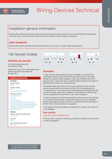
13A Socket Outlets<br />
Standards and approvals<br />
13A socket outlets comply with<br />
BS 1363 Part 2:1995.<br />
Replacement fuses to the 3 gang switchsocket<br />
outlets (Logic Plus only) comply with<br />
BS 1362:1973.<br />
TECHNICAL SPECIFICATION<br />
ELECTRICAL<br />
VOLTAGE RATING<br />
250V a.c.<br />
CURRENT RATING<br />
13A<br />
(3 Gang Switchsocket 13A total)<br />
TERMINAL CAPACITY<br />
Live, neutral & earth<br />
3 x 2.5mm²<br />
3 x 4mm²<br />
2 x 6mm² (standard)<br />
(Dual earth terminals on list Nos. K781, K2657,<br />
K2737, K2746, K2757, all standard Edge and Aspect<br />
<strong>sockets</strong>, K733, K2958, K2458, K2947, K2947D6,<br />
K850, K2977, K2477, K3045, K3077, K2945,<br />
K2945D6 and K5357)<br />
PHYSICAL<br />
AMBIENT OPERATING TEMPERATURE<br />
–5°C to +40°C<br />
IP RATING<br />
IP2XD<br />
MAX. INSTALLATION ALTITUDE<br />
2000 metres<br />
Description<br />
A range of socket outlets designed for ease of installation and having all the<br />
advantageous design features of the MK range of wiring devices. The 2 gang<br />
<strong>sockets</strong> with outboard rockers (available in Logic Plus and Albany Plus) are of<br />
particular value for use by the infirm and partially sighted whilst the same feature in<br />
Metalclad Plus is ideal for use with gloved hands.<br />
Non-standard clean earth <strong>sockets</strong> are for use on installations where restricted<br />
access is required and will only accept a 647WHI 13A non-standard plug with<br />
T-shaped earth pin. The <strong>sockets</strong> have two independent earth terminals so that they<br />
can also be used for ‘clean earth’ installations. The K2746CE and K2947CE also<br />
have two independent earth terminals for ‘clean earth’ installations.<br />
A variety of <strong>sockets</strong> (see <strong>Tech</strong>nical Specification) are fitted with two earth terminals<br />
on a common busbar to provide a <strong>double</strong> earth facility for use when installations<br />
require a high integrity protective connection as specified within the latest edition of<br />
BS 7671 which should be referred to for guidance.<br />
The products can be quickly installed as replacement for existing 13A <strong>sockets</strong> or in<br />
a new installation.<br />
Fuse carriers<br />
(Logic Plus 3 gang switchsocket only)<br />
The fuse carrier is opened by a fast-acting, screwdriver-operated, worm-drive screw<br />
for ease of replacement.<br />
For a full range of corresponding products,<br />
see pages 32-188 in the product selector.<br />
441
WIRING DEVICES<br />
Wiring Devices <strong>Tech</strong>nical<br />
mkelectric.co.uk<br />
13A Socket Outlets<br />
Installation<br />
1 gang switchsocket – view from rear<br />
Top-facing, angled, backed-out terminals<br />
make wiring easier and quicker.<br />
FEATURES<br />
l Moulded ‘on’ indicator flash on plastic<br />
switches will not rub off – totally safe<br />
l Matching Metal rocker Switches<br />
(Edge and Aspect only)<br />
l Optional neon indicators in the switch<br />
rockers with 175° visibility in the<br />
horizontal and vertical planes<br />
l 3 pin operated safety shutter<br />
l Printed terminal markings on grey rear<br />
mouldings for clearer identification<br />
l Top access, angled terminals make<br />
wiring easier and quicker<br />
l 3mm minimum switch contact gap<br />
l Double pole switching<br />
l Choice of inboard or outboard<br />
positioned rockers<br />
l Additional electrical safety from DP<br />
Switch, neutral ‘make first’, ‘break last’<br />
feature<br />
l Switch contacts with silver contacts<br />
on both surfaces for good continuity<br />
l Only one size of screwdriver required<br />
for installation<br />
l Selection of products incorporating<br />
dual earth terminals for high integrity<br />
earthing<br />
l Backed out and captive terminal<br />
screws<br />
l ‘Clean earth’ <strong>sockets</strong> available<br />
l Non-standard ‘clean earth’ <strong>sockets</strong><br />
available<br />
442
<strong>Tech</strong>nical Hotline<br />
+44 (0)1268 563720<br />
Wiring Devices <strong>Tech</strong>nical<br />
– Logic Plus<br />
2 Gang Switchsocket Outlet with Integrated<br />
Dual USB Charging Capability<br />
WIRING DEVICES<br />
Standards and approvals<br />
Logic Plus 13A socket outlets and 2A USB<br />
charging outlets comply with BS 5733 and<br />
IEC 61558-2-16.<br />
EMC Compatibility:<br />
IEC 61000-6-1<br />
IEC 61000-6-3<br />
Products are CE marked and meet the<br />
requirements of the Low Voltage, EMC, RoHS<br />
and WEEE directives.<br />
TECHNICAL SPECIFICATION<br />
13A SOCKET OUTLETS<br />
ELECTRICAL<br />
VOLTAGE RATING<br />
220-240V<br />
CURRENT RATING<br />
13A<br />
Combined total 2A drawn from USB outlets<br />
STANDBY POWER<br />
150mW<br />
TERMINAL CAPACITY<br />
Live, neutral & earth<br />
3 x 2.5mm 2<br />
3 x 4mm 2<br />
2 x 6mm 2 (stranded)<br />
PHYSICAL<br />
AMBIENT OPERATING TEMPERATURE<br />
–5°C to +40°C<br />
IP RATING<br />
IP2XD<br />
MAX. INSTALLATION ALTITUDE<br />
2000 metres<br />
Installation<br />
Logic Plus socket outlets can be wall or bench<br />
mounted.<br />
Do not mount or use as a trailing socket or<br />
where they may be subject to excessive<br />
moisture or damp.<br />
Description<br />
A range of socket outlets designed for ease of installation and having all the<br />
advantageous design features of the Logic Plus range. Dual USB charging outlets<br />
offer end users easy access to power for charging a variety of devices such as<br />
smart phones, tablets and cameras.<br />
FEATURES<br />
l Moulded ‘on’ indicator flash on<br />
switches will not rub off – totally safe<br />
l 3 pin operated safety shutter on 13A<br />
socket outlets<br />
l USB 2.0 and 3.0 compatible<br />
l Can charge a device at up to a full 2A<br />
l If only one device is connected to a<br />
USB outlet the total output current of<br />
2A is available from either outlet<br />
l If two devices are connected to USB<br />
outlets the the total rated current of 2A<br />
is divided between the two outlets<br />
l Differing manufacturers devices can<br />
be charged simultaneously via the two<br />
USB outlets<br />
l If the total charging current exceeds<br />
the rated level of 2A then the device will<br />
enter a current limiting safety mode<br />
l Electronically protected against an<br />
overload or short circuit on either USB<br />
outlet<br />
Dimensions (mm)<br />
l USB outlets are designed to provide<br />
optimum charging compatibility<br />
across a wide range of devices<br />
l Printed terminal markings on grey rear<br />
mouldings for clearer identification<br />
l Top access, angled terminals make<br />
wiring easier and quicker<br />
l 3mm minimum switch contact gap<br />
l Double pole switching<br />
l Additional electrical safety from<br />
neutral ‘make first’, ‘break last’ feature<br />
l Switch contacts with silver contacts<br />
on both surfaces for good continuity<br />
l Backed out and captive terminal<br />
screws<br />
l Dual earthed<br />
Cable management<br />
Logic Plus socket outlets can be mounted in a<br />
variety of MK trunking systems.<br />
146<br />
40<br />
BOX TYPES WITHOUT PATRESS<br />
GANG<br />
FLUSH<br />
SURFACE<br />
INSULATED<br />
SURFACE<br />
METAL<br />
86<br />
DEPTH 35MM DEPTH 40MM DEPTH 41MM<br />
2 GANG<br />
886 ZIC K2172 WHI<br />
K2212 ALM<br />
K2214 ALM<br />
120.6<br />
28<br />
443
WIRING DEVICES<br />
Wiring Devices <strong>Tech</strong>nical<br />
– Aspect<br />
2 Gang Switchsocket Outlet with Integrated<br />
Dual USB Charging Capability<br />
mkelectric.co.uk<br />
Standards and approvals<br />
Aspect 13A socket outlets and 2A USB<br />
charging outlets comply with BS 5733 and<br />
IEC 61558-2-16.<br />
EMC Compatibility:<br />
IEC 61000-6-1<br />
IEC 61000-6-3<br />
Products are CE marked and meet the<br />
requirements of the Low Voltage, EMC, RoHS<br />
and WEEE directives.<br />
TECHNICAL SPECIFICATION<br />
13A SOCKET OUTLETS<br />
ELECTRICAL<br />
VOLTAGE RATING<br />
220-240V<br />
Description<br />
A range of socket outlets designed for ease of installation and having all the<br />
advantageous design features of the Aspect range. Dual USB charging outlets offer<br />
end users easy access to power for charging a variety of devices such as smart<br />
phones, tablets and cameras.<br />
CURRENT RATING<br />
13A<br />
Combined total 2A drawn from USB outlets<br />
STANDBY POWER<br />
150mW<br />
TERMINAL CAPACITY<br />
Live, neutral & earth<br />
3 x 2.5mm 2<br />
3 x 4mm 2<br />
2 x 6mm 2 (stranded)<br />
PHYSICAL<br />
AMBIENT OPERATING TEMPERATURE<br />
–5°C to +40°C<br />
IP RATING<br />
IP2XD<br />
MAX. INSTALLATION ALTITUDE<br />
2000 metres<br />
Installation<br />
Aspect socket outlets can be wall or bench<br />
mounted.<br />
Do not mount or use as a trailing socket or<br />
where they may be subject to excessive<br />
moisture or damp.<br />
FEATURES<br />
l Slim screwless frontplate design<br />
l Matching metal rocker switches<br />
l 3 pin operated safety shutter on 13A<br />
socket outlets<br />
l USB 2.0 and 3.0 compatible<br />
l Can charge a device at up to a full 2A<br />
l If only one device is connected to a<br />
USB outlet the total output current of<br />
2A is available from either outlet<br />
l If two devices are connected to USB<br />
outlets the the total rated current of 2A<br />
is divided between the two outlets<br />
l Differing manufacturers devices can<br />
be charged simultaneously via the two<br />
USB outlets<br />
l If the total charging current exceeds<br />
the rated level of 2A then the device will<br />
enter a current limiting safety mode<br />
Dimensions (mm)<br />
l Electronically protected against an<br />
overload or short circuit on either USB<br />
outlet<br />
l USB outlets are designed to provide<br />
optimum charging compatibility<br />
across a wide range of devices<br />
l Printed terminal markings on grey rear<br />
mouldings for clearer identification<br />
l Top access, angled terminals make<br />
wiring easier and quicker<br />
l 3mm minimum switch contact gap<br />
l Double pole switching<br />
l Additional electrical safety from<br />
neutral ‘make first’, ‘break last’ feature<br />
l Switch contacts with silver contacts<br />
on both surfaces for good continuity<br />
l Backed out and captive terminal<br />
screws<br />
l Dual earthed<br />
Cable management<br />
Aspect socket outlets can be mounted in<br />
a variety of MK trunking systems.<br />
146.4<br />
40<br />
BOX TYPES WITHOUT PATRESS<br />
GANG<br />
FLUSH<br />
86.4<br />
2 GANG<br />
DEPTH 47MM<br />
878 ZIC<br />
444<br />
33
<strong>Tech</strong>nical Hotline<br />
+44 (0)1268 563720<br />
Wiring Devices <strong>Tech</strong>nical<br />
– Edge<br />
2 Gang Switchsocket Outlet with Integrated<br />
Dual USB Charging Capability<br />
WIRING DEVICES<br />
Standards and approvals<br />
Edge TM 13A socket outlets and 2A USB charging<br />
outlets comply with BS 5733 and<br />
IEC 61558-2-16.<br />
EMC Compatibility:<br />
IEC 61000-6-1<br />
IEC 61000-6-3<br />
Products are CE marked and meet the<br />
requirements of the Low Voltage, EMC, RoHS<br />
and WEEE directives.<br />
TECHNICAL SPECIFICATION<br />
13A SOCKET OUTLETS<br />
ELECTRICAL<br />
VOLTAGE RATING<br />
220-240V<br />
CURRENT RATING<br />
13A<br />
Combined total 2A drawn from USB outlets<br />
STANDBY POWER<br />
150mW<br />
TERMINAL CAPACITY<br />
Live, neutral & earth<br />
3 x 2.5mm 2<br />
3 x 4mm 2<br />
2 x 6mm 2 (stranded)<br />
PHYSICAL<br />
AMBIENT OPERATING TEMPERATURE<br />
–5°C to +40°C<br />
IP RATING<br />
IP2XD<br />
MAX. INSTALLATION ALTITUDE<br />
2000 metres<br />
Installation<br />
Edge TM socket outlets can be wall or bench<br />
mounted.<br />
Do not mount or use as a trailing socket or<br />
where they may be subject to excessive<br />
moisture or damp.<br />
Description<br />
A range of socket outlets designed for ease of installation and having all the<br />
advantageous design features of the Edge TM range. Dual USB charging outlets offer<br />
end users easy access to power for charging a variety of devices such as smart<br />
phones, tablets and cameras.<br />
FEATURES<br />
l Matching metal rocker switches<br />
l 3 pin operated safety shutter on 13A<br />
socket outlets<br />
l USB 2.0 and 3.0 compatible<br />
l Can charge a device at up to a full 2A<br />
l If only one device is connected to a<br />
USB outlet the total output current of<br />
2A is available from either outlet<br />
l If two devices are connected to USB<br />
outlets the the total rated current of 2A<br />
is divided between the two outlets<br />
l Differing manufacturers devices can<br />
be charged simultaneously via the two<br />
USB outlets<br />
l If the total charging current exceeds<br />
the rated level of 2A then the device will<br />
enter a current limiting safety mode<br />
l Electronically protected against an<br />
overload or short circuit on either USB<br />
outlet<br />
Dimensions (mm)<br />
l USB Outlets are designed to provide<br />
optimum charging compatibility<br />
across a wide range of devices<br />
l Printed terminal markings on grey rear<br />
mouldings for clearer identification<br />
l Top access, angled terminals make<br />
wiring easier and quicker<br />
l 3mm minimum switch contact gap<br />
l Double pole switching<br />
l Additional electrical safety from<br />
neutral ‘make first’, ‘break last’ feature<br />
l Switch contacts with silver contacts<br />
on both surfaces for good continuity<br />
l Backed out and captive terminal<br />
screws<br />
l Dual earthed<br />
Cable management<br />
Edge TM socket outlets can be mounted in<br />
a variety of MK trunking systems.<br />
146<br />
40<br />
BOX TYPES WITHOUT PATRESS<br />
GANG<br />
2 GANG<br />
FLUSH<br />
DEPTH 47MM<br />
878 ZIC<br />
86<br />
120.6<br />
35.7<br />
445
WIRING DEVICES<br />
Wiring Devices <strong>Tech</strong>nical<br />
– Albany Plus<br />
2 Gang Switchsocket Outlet with Integrated<br />
Dual USB Charging Capability<br />
mkelectric.co.uk<br />
Standards and approvals<br />
Albany Plus 13A socket outlets and 2A USB<br />
charging outlets comply with BS 5733 and<br />
IEC 61558-2-16.<br />
EMC Compatibility:<br />
IEC 61000-6-1<br />
IEC 61000-6-3<br />
Products are CE marked and meet the<br />
requirements of the Low Voltage, EMC, RoHS<br />
and WEEE directives.<br />
TECHNICAL SPECIFICATION<br />
13A SOCKET OUTLETS<br />
ELECTRICAL<br />
VOLTAGE RATING<br />
220-240V<br />
CURRENT RATING<br />
13A<br />
Combined total 2A drawn from USB outlets<br />
STANDBY POWER<br />
150mW<br />
TERMINAL CAPACITY<br />
Live, neutral & earth<br />
3 x 2.5mm 2<br />
3 x 4mm 2<br />
2 x 6mm 2 (stranded)<br />
PHYSICAL<br />
AMBIENT OPERATING TEMPERATURE<br />
–5°C to +40°C<br />
IP RATING<br />
IP2XD<br />
MAX. INSTALLATION ALTITUDE<br />
2000 metres<br />
Installation<br />
Albany Plus socket outlets can be wall or<br />
bench mounted.<br />
Do not mount or use as a trailing socket or<br />
where they may be subject to excessive<br />
moisture or damp.<br />
Description<br />
A range of socket outlets designed for ease of installation and having all the<br />
advantageous design features of the Albany Plus range. Dual USB charging<br />
outlets offer end users easy access to power for charging a variety of devices such<br />
as smart phones, tablets and cameras.<br />
FEATURES<br />
l Moulded ‘on’ indicator flash on<br />
switches will not rub off – totally safe<br />
l 3 pin operated safety shutter on 13A<br />
socket outlets<br />
l USB 2.0 and 3.0 compatible<br />
l Can charge a device at up to a full 2A<br />
l If only one device is connected to a<br />
USB outlet the total output current of<br />
2A is available from either outlet<br />
l If two devices are connected to USB<br />
outlets the the total rated current of 2A<br />
is divided between the two outlets<br />
l Differing manufacturers devices can<br />
be charged simultaneously via the two<br />
USB outlets<br />
l If the total charging current exceeds<br />
the rated level of 2A then the device will<br />
enter a current limiting safety mode<br />
l Electronically protected against an<br />
overload or short circuit on either USB<br />
outlet<br />
Dimensions (mm)<br />
l USB outlets are designed to provide<br />
optimum charging compatibility<br />
across a wide range of devices<br />
l Printed terminal markings on grey rear<br />
mouldings for clearer identification<br />
l Top access, angled terminals make<br />
wiring easier and quicker<br />
l 3mm minimum switch contact gap<br />
l Double pole switching<br />
l Additional electrical safety from<br />
neutral ‘make first’, ‘break last’ feature<br />
l Switch contacts with silver contacts<br />
on both surfaces for good continuity<br />
l Backed out and captive terminal<br />
screws<br />
l Dual earthed<br />
Cable management<br />
Albany Plus socket outlets can be mounted in<br />
a variety of MK trunking systems.<br />
146.1<br />
40<br />
BOX TYPES WITHOUT PATRESS<br />
GANG FLUSH<br />
SURFACE<br />
INSULATED<br />
SURFACE<br />
METAL<br />
85.8<br />
2 GANG<br />
DEPTH 35MM DEPTH 40MM DEPTH 41MM<br />
886 ZIC K2172 WHI<br />
K2212ALM /<br />
K2214ALM<br />
446<br />
120.6<br />
27.7
<strong>Tech</strong>nical Hotline<br />
+44 (0)1268 563720<br />
Wiring Devices <strong>Tech</strong>nical<br />
– Metalclad Plus<br />
2 Gang Switchsocket Outlet with Integrated<br />
Dual USB Charging Capability<br />
WIRING DEVICES<br />
Standards and approvals<br />
Metalclad Plus 13A socket outlets and 2A USB<br />
charging outlets comply with BS 5733 and<br />
IEC 61558-2-16.<br />
EMC Compatibility:<br />
IEC 61000-6-1<br />
IEC 61000-6-3<br />
Products are CE marked and meet the<br />
requirements of the Low Voltage, EMC, RoHS<br />
and WEEE directives.<br />
TECHNICAL SPECIFICATION<br />
13A SOCKET OUTLETS<br />
ELECTRICAL<br />
VOLTAGE RATING<br />
220-240V<br />
CURRENT RATING<br />
13A<br />
Combined total 2A drawn from USB outlets<br />
STANDBY POWER<br />
150mW<br />
TERMINAL CAPACITY<br />
Live, neutral & earth<br />
3 x 2.5mm 2<br />
3 x 4mm 2<br />
2 x 6mm 2 (stranded)<br />
PHYSICAL<br />
AMBIENT OPERATING TEMPERATURE<br />
–5°C to +40°C<br />
IP RATING<br />
IP2XD<br />
MAX. INSTALLATION ALTITUDE<br />
2000 metres<br />
Installation<br />
Metalclad Plus socket outlets can be wall or<br />
bench mounted.<br />
Do not mount or use as a trailing socket or<br />
where they may be subject to excessive<br />
moisture or damp.<br />
Description<br />
A range of socket outlets designed for ease of installation and having all the<br />
advantageous design features of the Metalclad Plus range. Dual USB charging<br />
outlets offer end users easy access to power for charging a variety of devices such<br />
as smart phones, tablets and cameras.<br />
FEATURES<br />
l Moulded ‘on’ indicator flash on<br />
switches will not rub off – totally safe<br />
l 3 pin operated safety shutter on 13A<br />
socket outlets<br />
l USB 2.0 and 3.0 compatible<br />
l Can charge a device at up to a full 2A<br />
l If only one device is connected to a<br />
USB outlet the total output current of<br />
2A is available from either outlet<br />
l If two devices are connected to USB<br />
outlets the the total rated current of 2A<br />
is divided between the two outlets<br />
l Differing manufacturers devices can<br />
be charged simultaneously via the two<br />
USB outlets<br />
l If the total charging current exceeds<br />
the rated level of 2A then the device will<br />
enter a current limiting safety mode<br />
l Electronically protected against an<br />
overload or short circuit on either USB<br />
outlet<br />
Dimensions (mm)<br />
l USB outlets are designed to provide<br />
optimum charging compatibility<br />
across a wide range of devices<br />
l Printed terminal markings on grey rear<br />
mouldings for clearer identification<br />
l Top access, angled terminals make<br />
wiring easier and quicker<br />
l 3mm minimum switch contact gap<br />
l Double pole switching<br />
l Additional electrical safety from<br />
neutral ‘make first’, ‘break last’ feature<br />
l Switch contacts with silver contacts<br />
on both surfaces for good continuity<br />
l Backed out and captive terminal<br />
screws<br />
l Metallic powder paint finish is<br />
corrosion and scratch resistant<br />
l Dual earthed<br />
l High impact resistance<br />
Cable management<br />
Metalclad Plus socket outlets can be mounted<br />
in a variety of MK trunking systems.<br />
146<br />
40<br />
BOX TYPES WITHOUT PATRESS<br />
GANG FLUSH SURFACE<br />
85.8<br />
DEPTH<br />
35MM<br />
DEPTH 38MM<br />
2 GANG<br />
886 ZIC<br />
K830 ALM (without knockouts)<br />
K897 ALM and K897 WHI<br />
(with 8 x 20mm knockouts)<br />
120.6<br />
27.7<br />
447
(tripped)<br />
red<br />
on<br />
Flag below Reset (R) button.<br />
Red : ON Black: OFF<br />
ALWAYS TEST BEFORE USE<br />
Press Test (T) button, Red flag should<br />
disappear. If it does not, do not use.<br />
Press Reset (R) after testing.<br />
WIRING DEVICES<br />
Wiring Devices <strong>Tech</strong>nical<br />
mkelectric.co.uk<br />
Sentrysocket<br />
Compliance with EC Directives,<br />
Standards and approvals<br />
All Sentry<strong>sockets</strong> comply with the following<br />
EC Directives and are CE marked:<br />
Low Voltage Directive<br />
Electromagnetic Compatibility Directive<br />
(89/336/EEC)<br />
Sentrysocket RCD DP Single Sockets comply<br />
with the requirements of the following standards:<br />
BS 7288:1990<br />
BS EN 50082-1:1998<br />
Sentrysocket RCD SP Double Sockets<br />
also comply with the requirements of<br />
BS EN 61543:1996.<br />
TECHNICAL SPECIFICATION<br />
ELECTRICAL<br />
RATED VOLTAGE<br />
240V a.c.<br />
CURRENT RATING<br />
13A resistive<br />
Rated tripping current 10mA/30mA<br />
TERMINAL CAPACITY<br />
3 x 4mm 2 for 1 gang<br />
2 x 4mm 2 for 2 gang<br />
PHYSICAL<br />
AMBIENT OPERATING TEMPERATURE<br />
–5°C to +40°C<br />
IP RATING<br />
IP2XD<br />
IP66 (K56301/K56231/K56233)<br />
MAX. INSTALLATION ALTITUDE<br />
2000 metres<br />
Sentry<strong>sockets</strong> are not suitable for connection across<br />
two lines of a 127V line to Neutral Voltage System<br />
Cable management<br />
Logic Plus, Albany Plus and Metalclad<br />
Plus Sentry<strong>sockets</strong> can be mounted in a variety<br />
of MK trunking systems.<br />
Installation<br />
Flush mounting steel wall box<br />
It should be noted that some of the conduit<br />
entries may be restricted, depending upon their<br />
positions and the depth of box used.<br />
Description<br />
Sentrysocket provides a high level of protection against electrocution and gives<br />
further protection when used with appliances vulnerable to insulation damage,<br />
particularly when they are in damp environments or outdoors. The Sentrysocket<br />
units are not suitable for mounting in damp environments or outdoors.<br />
Sentrysocket, incorporating an RCD, is part of a complete range of fixed and<br />
portable wiring devices and circuit protection devices suitable for use in domestic,<br />
commercial and light industrial applications.<br />
Active control circuits<br />
Incorporate a ‘Re-set’ mechanism and are mains failure sensitive, i.e. they will<br />
function under all the normal conditions expected of an RCD, but will also trip in<br />
the event of a power cut or a sudden, dramatic reduction in mains voltage. This<br />
makes them ideal for use where it would be hazardous for equipment to suddenly<br />
energise after return of mains power, such as use with rotating machinery and heat<br />
developing apparatus.<br />
Passive control circuits<br />
Incorporate a ‘Stay-set’ mechanism and is mains failure proof, i.e. it will function<br />
under all the normal conditions expected of an RCD and will not trip in the event<br />
of a power cut. This makes it suitable for use with freezers or in inaccessible or<br />
unmanned locations.<br />
FEATURES<br />
l Suitable for most residential,<br />
commercial and light industrial<br />
applications<br />
l Active and passive control circuit<br />
applications<br />
l Flexible and versatile in use<br />
l Single Sockets have <strong>double</strong> pole<br />
switching, <strong>double</strong> <strong>sockets</strong> are single<br />
pole switching<br />
l Masterseal Plus products are ideal<br />
for use with equipment subject to wet<br />
weather or high humidity<br />
l Part of a complete range of MK circuit<br />
protection devices<br />
l They are a.c. and pulsating d.c.<br />
sensitive for residual current<br />
l Double Socket products have an<br />
enhanced RF Immunity performance<br />
Sentry<strong>sockets</strong> products can be wall or bench mounted. Do not mount or use as a<br />
trailing socket or where they maybe subject to excessive moisture or dampness.<br />
Dimensions (mm)<br />
Single socket<br />
Double socket<br />
146 146<br />
3.3<br />
26.5<br />
T<br />
test before use<br />
press button - T<br />
sentrysocket<br />
rcd protected<br />
white<br />
off<br />
86<br />
on<br />
86<br />
active control<br />
device trips with<br />
loss of mains<br />
10mA tripping current<br />
T<br />
R<br />
sentrysocket<br />
rcd protected<br />
448<br />
120.6 120.6 9
<strong>Tech</strong>nical Hotline<br />
+44 (0)1268 563720<br />
Wiring Devices <strong>Tech</strong>nical<br />
WIRING DEVICES<br />
Sentrysocket<br />
Installation<br />
Flush mounting steel wall box<br />
It should be noted that some of the conduit entries may be restricted,<br />
depending upon their positions and the depth of box used.<br />
Socket Testing<br />
Single Socket Testing<br />
After installation, turn the mains electricity supply on.<br />
To test that the Sentrysocket is functioning correctly:<br />
1. Ensure that no appliance is connected to the Sentrysocket.<br />
Switch Sentrysocket on: The switch should remain closed<br />
and the red flag will appear in the window. If the switch fails to<br />
remain closed, check that the Supply L and N connections are<br />
not reversed or the Supply N connection is not open circuit. If<br />
the Sentrysocket is correctly connected and still trips after being<br />
switched on, the Sentrysocket is faulty and should not be used.<br />
2. If the Sentrysocket stays on, press the test button: The<br />
switch will open and the white flag will appear In the window.<br />
If the Sentrysocket does not trip and there is mains voltage<br />
present at the socket outlet, Sentrysocket is faulty and should<br />
not be used.<br />
3. Switch Sentrysocket on: Connect an RCD tester and ensure<br />
that the Sentrysocket trips within the specified time:<br />
≤ 200 ms AT RATED TRIP CURRENT<br />
≤ 40 ms AT 5 x RATED TRIP CURRENT<br />
If the Sentrysocket does not trip within the specified times then<br />
the product is faulty and should not be used (If more than one<br />
RCD is in series then there is no guarantee as to which device<br />
will trip first).<br />
Double Socket Testing<br />
After installation, turn the mains electricity supply on.<br />
To test that the Sentrysocket is functioning correctly follow the<br />
steps 1 to 4 below:<br />
1. Ensure that no appliance is connected to the Sentrysocket.<br />
2. Reset – Press the button marked R (for Reset) – the contact<br />
status indicator should show red, indicating that the socket<br />
outlets are now live (if the switches are in the ON positions).<br />
3. Test – Press the TEST button marked T (for Test), the product<br />
should trip with the contact status indicator showing black. In<br />
this state the socket outlets are disconnected from the supply.<br />
4. Reset – Press the button marked R again, the contact status<br />
indicator should show red.<br />
5. Connect an RCD Tester to either socket outlet and ensure that<br />
the Sentrysocket trips with the specified times below:<br />
≤ 200 ms AT RATED TRIP CURRENT<br />
≤ 40 ms AT 5 x RATED TRIP CURRENT<br />
6. Reset the Sentrysocket as in step 2 above.<br />
7. Switch off the Mains Supply Switch Disconnector.<br />
8. A Sentrysocket with Active Control Circuit should trip while a<br />
Sentrysocket with Passive Control Circuit should not trip.<br />
If all the operations in steps 2 to 8 above give correct results, the<br />
Sentrysocket RCD socket outlet is safe to use.<br />
If the procedures in steps 2 to 8 above are not completed<br />
correctly, do not use the Sentrysocket product and seek<br />
professional advice or contact the MK <strong>Tech</strong>nical Sales and<br />
Service department on +44 (0)1268 563720.<br />
4. Reset all tripped RCD’s including the Sentrysocket.<br />
5. Switch off the mains supply switch disconnector. On mains<br />
failure, a Sentrysocket with Active Control Circuit will trip, whilst<br />
a Sentrysocket with Passive Control Circuit will not trip. If the<br />
Active Control device does not trip, it is faulty and should not<br />
be used – see note below. If no faults have been found then<br />
installation testing has been completed successfully.<br />
Note: If a fault is identified at any stage of installation testing procedure do<br />
not use Sentrysocket, and contact your local electrician, or your local MK<br />
stockist.<br />
449
WIRING DEVICES<br />
Wiring Devices <strong>Tech</strong>nical<br />
mkelectric.co.uk<br />
Filtered Switchsocket Outlets (Logic Plus and Albany Plus)<br />
Standards and approvals<br />
Filtered socket outlets comply with<br />
BS 5733:2010.<br />
TECHNICAL SPECIFICATION<br />
ELECTRICAL<br />
CURRENT RATING<br />
13A maximum total for 2 <strong>sockets</strong><br />
VOLTAGE RATING<br />
250V a.c.<br />
EARTH LEAKAGE<br />
0.5 mA<br />
SUPPRESSION<br />
150 kHz – 30 MHz (transients)<br />
MAXIMUM ENERGY ABSORPTION<br />
140 Joules L – N<br />
140 Joules L – E<br />
TERMINAL CAPACITY<br />
2 x 6mm²<br />
3 x 4mm²<br />
3 x 2.5mm²<br />
3 x 1.5mm²<br />
PHYSICAL<br />
AMBIENT OPERATING TEMPERATURE<br />
-5°C to +40°C<br />
THERMAL OVERLOAD<br />
The K1826 and K2826 filter socket incorporates a<br />
thermal overload device in the RFI filter section.<br />
Overload current causes temperature rise, resulting in<br />
automatic ‘trip out’. The overload device will re-set as<br />
the temperature falls.<br />
IP RATING<br />
IP2XD<br />
MAX. INSTALLATION ALTITUDE<br />
2000 metres<br />
Description<br />
A range of <strong>sockets</strong> in the Logic Plus and Albany Plus styles, designed to combat<br />
interference to or data losses on sensitive electrical products and systems due to<br />
mains borne voltage spikes and RFI.<br />
Such systems include:<br />
l Computer or microprocessor based equipment<br />
l Telecommunications systems<br />
l Electronic measurement equipment<br />
l Cash registers<br />
l Audio visual and hi-fi equipment<br />
These products can be quickly installed as replacements for existing twin 13A<br />
<strong>sockets</strong> or in a new installation.<br />
Fitted with two earth terminals to provide a <strong>double</strong> earth facility for use when<br />
installations require a high integrity protective connection as specified within the<br />
latest edition of BS 7671.<br />
Filter cassettes<br />
Filter cassettes are supplied with <strong>sockets</strong> and have an LED which shows green<br />
under normal conditions but will turn red or extinguish when a replacement cassette<br />
(K1800WHI) is required. An alarm will also beep at 5 second intervals to indicate<br />
replacement necessity. It can be de-activated if required.<br />
FEATURES<br />
l Moulded ‘on’ indicator flash on<br />
switches will not rub off – totally safe<br />
l 3 pin operated safety shutter<br />
l Printed terminal markings on grey rear<br />
mouldings for clearer identification<br />
l Reduces risk of damage to equipment<br />
and down time<br />
l Reduces risk of data loss<br />
l 2 way filtering – into appliance and<br />
back into mains supply<br />
l Additional electrical safety from DP<br />
Switch, neutral ‘make first’, ‘break last’<br />
feature<br />
l Double pole switches<br />
l Dual earth terminals for high integrity<br />
earthing<br />
l Clearly visible LED on filter cassette,<br />
changes from green to red when<br />
replacement required<br />
l Simple replacement of cassettes<br />
l 10 year guarantee (except filter<br />
cassette)<br />
l 3mm minimum switch contact gap<br />
l Backed out and captive terminal<br />
screws<br />
450
<strong>Tech</strong>nical Hotline<br />
+44 (0)1268 563720<br />
Wiring Devices <strong>Tech</strong>nical<br />
WIRING DEVICES<br />
Filtered Switchsocket Outlets<br />
Product features<br />
Filter indicator<br />
Audible warning<br />
Ensure that the connecting pins protruding from the<br />
connector<br />
bottom of<br />
the replacement Replacement Filter Cassette are not damaged or bent before<br />
installation. filter If in cassette doubt, contact MK <strong>Tech</strong>nical Sales Service<br />
Department on +44 (0)1268 563720.<br />
Locking screw<br />
The MK Filtered Switchsocket, in common with many other<br />
filters uses Voltage Dependant Resistors for spike suppression<br />
purposes. The performance of these devices will eventually<br />
degrade with use to a level where they will no longer provide<br />
adequate protection.<br />
Figure 2<br />
When this occurs the spike filer performance of the MK Filtered<br />
Switchsocket outlet can be restored by replacing the filter cassette.<br />
When the filter cassette needs replacing, the green indicator on<br />
the Replacement Filer Cassette will glow red or go out, an audible<br />
beep every five seconds may also be heard.<br />
Note: As with all filters, these Filter Sockets will reduce the magnitude<br />
of RFI and spikes and consequently their ability to interfere with<br />
connected equipment. They will not completely remove the<br />
interference from the supply.<br />
Figure<br />
Filter<br />
1indicator<br />
Audible warning<br />
connector<br />
Replacement<br />
filter cassette<br />
Filter indicator<br />
Audible warning<br />
connector<br />
4. Fit the new filter cassette by carefully sliding it into the aperture<br />
and gently pushing it down while turning the screw clockwise<br />
until the filter cassette is flush with the surface. Do not turn<br />
the screw any further as this will cause distortion of the plastic<br />
mouldings.<br />
Product and packaging can safely be disposed of via standard<br />
refuse facilities at the end of its useful life.<br />
Figure 2a<br />
Locking screw<br />
Installation<br />
Replaceable Spike Filter Cassette<br />
Note: To ensure a safe installation;<br />
l this product should be installed by a competent person.<br />
l it is important that all connections are made as instructed.<br />
1. The filter cassette can be removed and replaced without switching<br />
off the mains or removing any plugs from the filter socket.<br />
Figure 2b<br />
Audible warning<br />
connector<br />
2. Remove the filter cassette by turning the jacking screw anticlockwise<br />
to partially eject it (see Figure 2), and then gently<br />
pulling the cassette upwards, (see Figure 2a).<br />
3. Only fit the MK Replacement Filter Cassette (K1800WHI).<br />
Unpack the new filer cassette and check that the pins along the<br />
bottom edge are not bent or broken. If these pins are damaged,<br />
do not fit the replacement cassette. The audible sound indicating<br />
that the filter cassette needs replacing, is optional. It may be<br />
prevented by removing the small connector on the two end pins,<br />
(see Figure 2b), before fitting it into the socket.<br />
451
WIRING DEVICES<br />
Wiring Devices <strong>Tech</strong>nical<br />
mkelectric.co.uk<br />
Round Pin Socket Outlets<br />
Standards and approvals<br />
Round pin socket outlets comply with<br />
BS 546:1950.<br />
TECHNICAL SPECIFICATION<br />
ELECTRICAL<br />
VOLTAGE RATING<br />
250V a.c.<br />
TERMINAL CAPACITIES<br />
2A <strong>sockets</strong>:<br />
7 x 1mm²<br />
4 x 1.5mm²<br />
2 x 2.5mm²<br />
1 x 4mm²<br />
5A <strong>sockets</strong>:<br />
3 x 2.5mm ²<br />
2 x 4mm ²<br />
2 x 6mm ² (stranded)<br />
15A <strong>sockets</strong>:<br />
3 x 2.5mm²<br />
3 x 4mm²<br />
2 x 6mm² (stranded)<br />
PHYSICAL<br />
AMBIENT OPERATING TEMPERATURE<br />
-5°C to +40°C<br />
IP RATING<br />
IP2XD<br />
MAX. INSTALLATION ALTITUDE<br />
2000 metres<br />
Description<br />
A range of round pin socket outlets designed for ease of installation and having all<br />
the advantages and design features of the MK range of wiring devices.<br />
These products can be quickly installed as replacements for existing socket outlets<br />
or in new installations.<br />
FEATURES<br />
l Top access terminals make wiring<br />
easier and quicker<br />
l Integral ON indicator on plastic<br />
switches will not rub off – totally safe<br />
l Switch contact gap, 3mm minimum<br />
l Double pole switching<br />
l Terminal screws backed out<br />
l Additional electrical safety from<br />
neutral “make first”, “break last”<br />
feature on switched <strong>sockets</strong><br />
l Switch contacts with silver contact<br />
points on both surfaces for good<br />
continuity<br />
l 5A and 15A <strong>sockets</strong> contain a 3 pin<br />
operated safety shutter.<br />
l Printed terminal markings on grey rear<br />
mouldings for clearer identification<br />
452
<strong>Tech</strong>nical Hotline<br />
+44 (0)1268 563720<br />
Wiring Devices <strong>Tech</strong>nical<br />
WIRING DEVICES<br />
Non UK Socket Outlets<br />
Standards and approvals<br />
15A American <strong>sockets</strong> comply with<br />
SASO 2004:2003<br />
15A AMERICAN (Logic Plus*)<br />
16A 2P+E German <strong>sockets</strong> comply with<br />
IEC 60884-1:2006<br />
TECHNICAL SPECIFICATION<br />
ELECTRICAL<br />
15A AMERICAN<br />
VOLTAGE RATING<br />
127V a.c.<br />
CURRENT RATING<br />
15A<br />
TERMINAL CAPACITY<br />
Live, neutral & earth<br />
3 x 2.5mm²<br />
2 x 4mm²<br />
1 x 6mm² (stranded)<br />
BOX TYPES<br />
GANG<br />
FLUSH<br />
FLUSH<br />
(FOR EXTRA WIRING SPACE)<br />
SURFACE<br />
1 GANG 861ZIC 866ZIC K2140WHI<br />
2 GANG 862ZIC 886ZIC K2142WHI<br />
16A 2P+E GERMAN (Logic Plus*)<br />
MAX. INSTALLATION ALTITUDE<br />
2000 metres<br />
16A 2P+E GERMAN SOCKET<br />
VOLTAGE RATING<br />
250V a.c.<br />
CURRENT RATING<br />
16A<br />
TERMINAL CAPACITY<br />
Live, neutral & earth<br />
4 x 1.5mm²<br />
2 x 2.5mm²<br />
1 x 4mm²<br />
PHYSICAL<br />
AMBIENT OPERATING TEMPERATURE<br />
-5°C to +40°C<br />
IP RATING<br />
IP2XD<br />
MAX. INSTALLATION ALTITUDE<br />
2000 metres<br />
BOX TYPES<br />
GANG FLUSH SURFACE<br />
1 GANG 861ZIC K2140WHI<br />
2 GANG 862ZIC K2142WHI<br />
Note: 16A 2P+E German Outlet: These products are NOT suitable for<br />
25mm deep boxes.<br />
*15A American Sockets and 16A 2P+E German Sockets are also<br />
available in a modular format for MK decorative wiring device ranges.<br />
453
WIRING DEVICES<br />
Wiring Devices <strong>Tech</strong>nical<br />
mkelectric.co.uk<br />
Three Pole Fan Isolators<br />
Standards and approvals<br />
Comply with BS EN 60669-2-4:2005<br />
TECHNICAL SPECIFICATION<br />
ELECTRICAL<br />
VOLTAGE RATING<br />
250V a.c.<br />
CURRENT RATING<br />
10A<br />
RATED CONDITIONAL SHORT<br />
CIRCUIT CURRENT (Inc)<br />
3000A<br />
TERMINAL CAPACITY<br />
4 x 1mm²<br />
4 x 1.5mm²<br />
3 x 2.5mm²<br />
2 x 4mm²<br />
1 x 6mm²<br />
CONTACT GAP<br />
4mm switch contact gap<br />
RECOMMENDED SCPD<br />
GE Power Controls TIA32M40 32A IEC269-2-1 Fuse-link<br />
PHYSICAL<br />
AMBIENT OPERATING TEMPERATURE<br />
-5°C to +40°C<br />
IP RATING<br />
IP4X<br />
MAX. INSTALLATION ALTITUDE<br />
2000 metres<br />
Description<br />
The MK Three Pole Fan Isolator provides a safe and simple method of isolating<br />
mechanical fan units and is particularly useful in bathrooms, toilets, storerooms and<br />
basements where there is little or no natural light.<br />
For example, timer controlled fans are often linked into the lighting circuit for energy<br />
saving and convenience. In such an installation there is often a need for the lighting<br />
circuit to remain live to provide light whilst the fan unit is externally isolated so that<br />
routine maintenance and repairs can be carried out in complete safety.<br />
The fan isolator can be used as a <strong>double</strong> pole or triple pole isolator. In addition it<br />
includes a clear on/off indicator and the frontplate features a fan isolator symbol for<br />
easy circuit identification.<br />
Wiring diagrams<br />
Two pole switching for fan units without timers<br />
N<br />
L<br />
Supply<br />
Rear view of<br />
Fan Isolator<br />
L1 L2 N<br />
L1 L2 N<br />
TOP<br />
To Fan Unit without Timer<br />
(see Fan Unit Intructions)<br />
N<br />
L (switched)<br />
Features<br />
N<br />
L<br />
Supply<br />
TOP<br />
l Switchlock list no. K4858 is available to allow<br />
the isolator to be locked in the disconnected<br />
position to facilitate fan maintenance<br />
Rear view of<br />
Fan Isolator<br />
L1<br />
L1<br />
L2<br />
L2<br />
N<br />
N<br />
To Fan Unit without Timer<br />
(see Fan Unit Intructions)<br />
N<br />
L (switched)<br />
Three pole switching for fan units incorporating timers<br />
N<br />
L<br />
Supply<br />
TOP<br />
L1<br />
L1<br />
L2<br />
L2<br />
N<br />
N<br />
Rear view of<br />
Fan Isolator<br />
To Fan Unit with Timer<br />
(see Fan Unit Intructions)<br />
N<br />
L (unswitched)<br />
L (switched)<br />
N<br />
L<br />
Supply<br />
TOP<br />
L1<br />
L1<br />
L2<br />
L2<br />
N<br />
N<br />
454<br />
Rear view of<br />
Fan Isolator<br />
To Fan Unit with Timer<br />
(see Fan Unit Intructions)<br />
N<br />
L (unswitched)<br />
L (switched)
<strong>Tech</strong>nical Hotline<br />
+44 (0)1268 563720<br />
Wiring Devices <strong>Tech</strong>nical<br />
– Logic Plus<br />
WIRING DEVICES<br />
Shaver Socket Outlets<br />
Standards and approvals<br />
Shaver socket outlets comply with<br />
BS 4573:1970 and IEC 60884-1:2006.<br />
Plug pin apertures, and engagement face<br />
dimensions comply with BS 4573:1970.<br />
TECHNICAL SPECIFICATION<br />
ELECTRICAL<br />
VOLTAGE RATING<br />
200-250V a.c. Input<br />
MAXIMUM LOAD<br />
200 mA (internal thermister trip current)<br />
TERMINAL CAPACITIES<br />
Each terminal will accommodate<br />
1 x 4mm², or 2 x 2.5mm², 3 x 1.5 solid conductors<br />
PHYSICAL<br />
AMBIENT OPERATING TEMPERATURE<br />
-5°C to +40°C<br />
IP RATING<br />
IP2XD<br />
MAX. INSTALLATION ALTITUDE<br />
2000 metres<br />
Description<br />
Designed for ease of installation and having many of the advantageous features of<br />
the Logic Plus TM range.<br />
The shaver socket outlet accommodates the following plugs:<br />
British 5mm dia pins on 16.6mm pitch (230V socket) to BS 4573:1970.<br />
European 4mm dia pins on 17 to 19mm pitch (230V socket) to IEC 83:1975<br />
Standard C5.<br />
Australian 6.5 x 1.6 flat blades each set at 30° to the vertical on a nominal pitch of<br />
13.7mm (230V socket).<br />
AS C112:1964.<br />
The fuse carrier is captive and opened by a fast acting, screwdriver operated worm<br />
drive screw for ease of replacement.<br />
FEATURES<br />
l Top access terminals make wiring<br />
quicker and easier<br />
l Only one size of screwdriver required<br />
for installation<br />
l Terminal screws supplied ‘backed out’<br />
and held captive within the terminal<br />
moulding<br />
l White printed terminal markings<br />
on grey rear mouldings for clearer<br />
identification<br />
l Front plate fixing screws retained on<br />
rear case moulding<br />
Installation<br />
This shaver socket must not be used in bathrooms and washrooms. Non-isolated,<br />
fused, shaver socket outlets must never be installed in any location subject to<br />
splashes, condensation or damp conditions.<br />
For installation in any other room where a wash basin or shower cubicle is installed<br />
then refer to the current IET wiring regulations.<br />
455
WIRING DEVICES<br />
Wiring Devices <strong>Tech</strong>nical<br />
mkelectric.co.uk<br />
Shaver/Toothbrush Supply Units<br />
Standards and approvals<br />
Shaver/Toothbrush supply units comply with<br />
BS 61558-2-5:1998<br />
Accommodates plugs as follows:<br />
l British 5mm dia pins on 16.6mm pitch (230V<br />
socket) to BS 4573:1970.<br />
l European 4mm dia pins on 17 to 19mm pitch<br />
(230V socket) to BS EN 50075<br />
l Australian 6.5 x 1.6 flat blades each set<br />
at 30° to the vertical on a nominal pitch of<br />
13.7mm (230V socket) AS/NZS 3112:2000<br />
l American 6.6 x 1.6 flat horizontal blades<br />
on 12.7mm pitch (115V socket) to UL498 /<br />
NEMA WD6.<br />
TECHNICAL SPECIFICATION<br />
ELECTRICAL<br />
VOLTAGE RATING<br />
K701: 230V a.c. Input (will operate at 220-250V a.c.)<br />
K706: 127V a.c. Input (will operate at 110-130V a.c.)<br />
230V or 115V nominal outputs<br />
CURRENT RATING<br />
K701: 200mA max.<br />
(internal thermister trip current)<br />
K706: 400mA max.<br />
(internal thermister trip current)<br />
MAXIMUM LOAD<br />
20VA<br />
No load voltage < 275V<br />
TERMINAL CAPACITIES<br />
Each terminal will accommodate 1 x 4mm² or<br />
2 x 2.5mm² solid conductors<br />
PHYSICAL<br />
AMBIENT OPERATING TEMPERATURE<br />
-5°C to +40°C<br />
IP RATING<br />
IP41 (In Zone 2 if fixed where direct spray from<br />
showers is unlikely)<br />
Description<br />
Designed for ease of installation and having many of the advantageous design<br />
features of the MK range of wiring devices.<br />
May be used in bathrooms and washrooms – must only be installed in accordance<br />
with the latest edition of BS 7671.<br />
FEATURES<br />
l Top access terminal screws make<br />
wiring quicker and easier<br />
l Automatic primary supply switching<br />
on insertion of plug<br />
l Choice of 230V or 115V output socket<br />
positions<br />
l Safety interlocked shutters to prevent<br />
insertion of two plugs simultaneously<br />
Installation<br />
Shaver/Toothbrush supply unit should be wall mounted.<br />
l Only one size of screwdriver required<br />
for installation<br />
l Front plate fixing screws retained on<br />
rear case moulding<br />
l Integral over current device to protect<br />
transformer<br />
l Suitable for use with electric<br />
toothbrush chargers<br />
MAX. INSTALLATION ALTITUDE<br />
2000 metres<br />
456
<strong>Tech</strong>nical Hotline<br />
+44 (0)1268 563720<br />
Wiring Devices <strong>Tech</strong>nical<br />
WIRING DEVICES<br />
13A Connection Units, 20A Switches and Flex Outlets<br />
Standards and approvals<br />
All Connection Units comply with<br />
BS 1363-4:1995.<br />
All 20A DP Switches comply with<br />
BS EN 60669-1:1999.<br />
Flex Outlet complies with<br />
BS EN 60670-22:2006.<br />
Fuses comply with BS 1362:1973.<br />
TECHNICAL SPECIFICATION<br />
ELECTRICAL<br />
VOLTAGE RATING<br />
250V a.c.<br />
CURRENT RATING<br />
Connection Units: 13A<br />
DP switches: 20A<br />
Flex outlets: 20A<br />
TERMINAL CAPACITY<br />
Supply terminal:<br />
2 x 6mm² stranded<br />
2 x 4mm²<br />
3 x 2.5mm²<br />
Load terminals:<br />
2 x 6mm² stranded<br />
2 x 4mm²<br />
3 x 2.5mm²<br />
CORD GRIP CAPACITY<br />
Connection units:<br />
min: 2 core, 0.5mm<br />
max: 3 core, 1.5mm<br />
20A DP switches & flex outlet plate:<br />
min: 3 core, 1.5mm<br />
max: 3 core, 2.5mm<br />
PHYSICAL<br />
AMBIENT OPERATING TEMPERATURE<br />
-5°C to +40°C<br />
IP RATING<br />
With flex outlet: IP2XD<br />
Without flex outlet: IP4X<br />
MAX. INSTALLATION ALTITUDE<br />
2000 metres<br />
Description<br />
A range of 13A fused connection units and 20A DP switches designed for the<br />
connection of refrigerators, water heaters, central heating boilers and other fixed<br />
appliances.<br />
The ranges are designed for ease of instal la tion and have the advantageous design<br />
features of the MK range of wiring devices.<br />
Neon indicators<br />
Products are available with Neon indicators included in the rockers of the switched<br />
connection units. In the case of unswitched units, they are positioned centrally and<br />
uppermost on the face plate. Neon indicators are integrally wired into the product<br />
and do not require separate connection when installing. The design gives 175°<br />
visibility in the horizon tal and vertical planes.<br />
Fuse carriers<br />
These are captive and are opened by a fast acting, screwdriver operated worm<br />
drive for ease of replacement. A tamper-proof version is also available.<br />
Fuse carriers can be locked open using a padlock, List No. K2000.<br />
Flex outlets<br />
Bottom outlet types are supplied with blanking plug allowing use where the bottom<br />
outlet is not required.<br />
The products are equipped with very strong, push-fit nylon cord grips making<br />
installation safe, quick and easy.<br />
Flex outlet plate<br />
An unfused flex outlet with cord grip and 3 pairs of terminals.<br />
Installation<br />
Wiring<br />
Products must be installed in accordance with current IET Regulations.<br />
Changing Fuses<br />
1. Unscrew the fuse carrier screw to partially eject the carrier.<br />
2. Carefully lever the carrier out further to remove the fuse.<br />
Note: The carrier does not come fully out.<br />
3. Always replace with a BS 1362 type fuse (as used in 13A plugs) of the correct<br />
rating.<br />
4. Consistent fuse blowing could mean a faulty appliance. If in doubt, consult a<br />
qualified electrician.<br />
5. Push carrier back until engaging with jacking screw. Screw the carrier down until<br />
flush with surface of the plate. Do not over tighten the screw.<br />
457
WIRING DEVICES<br />
Wiring Devices <strong>Tech</strong>nical<br />
mkelectric.co.uk<br />
13A Connection Units, 20A Switches and Flex Outlets<br />
FEATURES<br />
l Optional indicators in the switch rockers with<br />
175° visibility in the horizontal and vertical<br />
planes<br />
l Worm-drive operated fuse carriers for<br />
additional security (tamper-proof version<br />
available)<br />
l Fuse carrier lockable in open position<br />
l All supply and load cables can be cut and<br />
stripped to the same length<br />
l Integrally wired Neon indicators save<br />
installation time<br />
l Push-fit cord grips, for safer, quicker<br />
installation<br />
l Angled, top mounted terminal screws simplify<br />
wiring<br />
l Moulded ‘on’ indicator flash on switches cannot<br />
rub off – totally safe<br />
l Captive fuse carrier<br />
l Additional electrical safety from DP Switch,<br />
neutral ‘make first’, ‘break last’ feature<br />
l Secure cable and flexible cord connection<br />
l All terminal and fixing screws operated by onesize<br />
(4mm) screwdriver<br />
l Backed out and captive terminal screws<br />
Supply and load cable cords cut<br />
and stripped to same length<br />
Bottom outlet and<br />
cord grip<br />
Blanking plug for<br />
bottom outlet<br />
Note: These switches are not recommended for<br />
switching large banks of PCs<br />
Front outlet cord grip<br />
Lockable fuse carrier<br />
K1090WHI Flex Outlet<br />
Supply and non flexible load<br />
cables<br />
458
<strong>Tech</strong>nical Hotline<br />
+44 (0)1268 563720<br />
Wiring Devices <strong>Tech</strong>nical<br />
WIRING DEVICES<br />
20A Key Operated Fire Alarm Isolator Switch<br />
TECHNICAL SPECIFICATION<br />
ELECTRICAL<br />
VOLTAGE RATING<br />
250V a.c.<br />
CURRENT RATING<br />
20A<br />
TERMINAL CAPACITIES<br />
Live, Neutral & Earth<br />
3 x 2.5mm²<br />
3 x 4mm²<br />
2 x 6mm²<br />
PHYSICAL<br />
AMBIENT OPERATING TEMPERATURE<br />
–5°C to +40°C<br />
IP RATING<br />
IP2XD<br />
Description<br />
The isolators comply with BS 60669-2-4:2005<br />
The Isolator is intended for use with building alarm systems that are required to<br />
comply with BS 5839 Part 1.<br />
MAX. INSTALLATION ALTITUDE<br />
2000 metres<br />
FEATURES<br />
l The built in lock ensures power cannot<br />
be provided without the key being<br />
operated, making it safe to carry out<br />
maintenance to fire alarms<br />
l Printed terminal markings on grey<br />
rear of the switch moulding for clearer<br />
identification<br />
l Double Pole switching<br />
l Only one size of screwdriver required<br />
for installation<br />
Note: The lock fitted to these isolators is universal for all MK 20A Isolators in the range<br />
i.e. a common key profile.<br />
However, the keys are different to those used on all other MK Key Operated Switched Products,<br />
for added security.<br />
459
WIRING DEVICES<br />
Wiring Devices <strong>Tech</strong>nical<br />
mkelectric.co.uk<br />
High Current Switches and Cooker Control Units<br />
Standards and approvals<br />
All DP switches in the range comply with<br />
BS EN 60669-1:1999.<br />
All Cooker Control Units in the range comply<br />
with BS 4177:1992.<br />
Cooker Connection Unit comply with<br />
BS EN 60670-22:2006<br />
TECHNICAL SPECIFICATION<br />
ELECTRICAL<br />
VOLTAGE RATING<br />
250V a.c.<br />
CURRENT RATING<br />
32A Switch<br />
45A Cooker Control Unit<br />
45A Cooker Connection Unit<br />
50A Switch (Resistive Load)<br />
SWITCH<br />
3mm contact gap<br />
Double pole operation –<br />
except socket switch on Cooker Control Units<br />
TERMINAL CAPACITY 50A SWITCHES<br />
Cooker Control Units, and Cooker Connection Units:<br />
4 x 4mm²<br />
3 x 6mm²<br />
1 x 10mm²<br />
1 x 16mm²<br />
TERMINAL CAPACITY, 32A SWITCH<br />
3 x 2.5mm²<br />
2 x 4mm²<br />
1 x 6mm²<br />
PHYSICAL<br />
AMBIENT OPERATING TEMPERATURE<br />
-5°C to +40°C<br />
IP RATING<br />
IP2XD<br />
Cooker Control Units<br />
Description<br />
A range of switches and cooker control units suitable for the switching of all<br />
domestic, commercial and industrial appliances where higher current ratings are<br />
required, i.e. cookers, heaters, units etc. Metal units are particularly suitable for<br />
refurbishment projects.<br />
FEATURES<br />
l Positive switch action<br />
l Positive <strong>double</strong> pole switching<br />
l Toggle action switches<br />
Note: These switches are not recommended for<br />
switching large banks of PCs<br />
l Metal front plates available<br />
l Replaceable neon indicators<br />
l Wide product choice<br />
IP4X<br />
32A Switch, 50A Switch, Cooker Connection Unit<br />
MAX. INSTALLATION ALTITUDE<br />
2000 metres<br />
460
<strong>Tech</strong>nical Hotline<br />
+44 (0)1268 563720<br />
Wiring Devices <strong>Tech</strong>nical<br />
WIRING DEVICES<br />
Plateswitches<br />
Standards and approvals<br />
All MK plateswitches comply with<br />
BS EN 60669-1:1999.<br />
TECHNICAL SPECIFICATION<br />
ELECTRICAL<br />
VOLTAGE RATING<br />
250V a.c.<br />
CURRENT RATING<br />
10A – no derating when used on fluorescent<br />
or inductive loads<br />
20A – no derating when used on fluorescent<br />
or inductive loads<br />
Push / Retractive switch types are not intended for<br />
fluorescent loads.<br />
TERMINAL CAPACITY<br />
4 x 1mm²<br />
4 x 1.5mm²<br />
3 x 2.5mm²<br />
2 x 4mm²<br />
1 x 6mm²<br />
CONTACT GAP<br />
3mm switch contact gap<br />
PHYSICAL<br />
AMBIENT OPERATING TEMPERATURE<br />
-5°C to +40°C<br />
IP RATING<br />
IP2XD<br />
MAX. INSTALLATION ALTITUDE<br />
2000 metres<br />
Operational testing (all plateswitches): tested to<br />
100,000 operations for mechanical life tested to<br />
40,000 operations at 10A rating tested to 10,000<br />
operations at 20A rating.<br />
Description<br />
MK plateswitches are designed to blend in with the decor, whilst complementing<br />
a wide range of other MK wiring devices. They are designed for easy installation<br />
in plasterdepth boxes and are suitable for controlling lighting circuits in domestic,<br />
commercial and industrial applications.<br />
Neon locator<br />
A textured, polycarbonate moulding allowing the glow of the neon to be seen<br />
at almost any angle. Designed to complement the Logic Plus 1, 2, or 3 gang<br />
plateswitches.<br />
It is easy to install in existing locations. For 3 gang applications using a 25mm deep<br />
box simplifies wiring.<br />
FEATURES<br />
l Two way switches can be wired as one or two<br />
way<br />
l Matching Grid switches available in 10 or<br />
20A ratings<br />
l 3mm switch contact gap<br />
l Positive switch action<br />
l Top access, backed out and captive terminal<br />
screws<br />
l Neon locator available making switch easy to<br />
find in darkened rooms (Logic Plus TM only)<br />
461
WIRING DEVICES<br />
Wiring Devices <strong>Tech</strong>nical<br />
mkelectric.co.uk<br />
ng<br />
Common<br />
Plateswitches<br />
1<br />
L<br />
Wiring N diagrams<br />
One-way switching<br />
Lamp/s<br />
ngg<br />
ng<br />
ng<br />
g<br />
ngg<br />
g<br />
ching g<br />
L<br />
N<br />
L<br />
N<br />
L<br />
N<br />
L<br />
L<br />
N<br />
Common<br />
Common<br />
Common<br />
1 1 2 Two-way switches 2<br />
1 Common<br />
1<br />
1<br />
Lamp/s<br />
Lamp/s<br />
Dotted lines Lamp/s show alternative switch positions<br />
Lamp/s<br />
Two-way switching – 2 wire control<br />
Lamp/s<br />
1<br />
1<br />
1<br />
Common<br />
Common<br />
Common<br />
2 Two-way switches 2<br />
2 Two-way Common<br />
Common<br />
switches 2<br />
1 2 Two-way switches<br />
1 2 Two-way switches 2<br />
SW.L<br />
1<br />
1<br />
1<br />
Common<br />
Common<br />
Common<br />
Lamp/s<br />
Lamp/s<br />
Dotted lines show alternative switch positions<br />
Dotted lines show alternative switch positions<br />
Dotted lines<br />
Lamp/s<br />
show alternative switch positionsLamp/s<br />
Dotted lines show alternative switch positions<br />
Two-way switching plus intermediate switching<br />
– 2 wire control<br />
1<br />
1<br />
2<br />
2<br />
1<br />
SW.L<br />
SW.L<br />
SW.L<br />
Common<br />
Common<br />
Common<br />
Common 2<br />
2 Two-way switches 1<br />
2 Two-way Commonswitches<br />
1<br />
Two-way Two-way switches 2 1<br />
1 switch<br />
2<br />
2 Two-way switches 1<br />
1<br />
Common<br />
Common<br />
2<br />
Common<br />
Common<br />
Common<br />
1<br />
2<br />
2 Common<br />
Intermediate<br />
1<br />
switch 1<br />
2<br />
Lamp/s<br />
Lamp/s<br />
Dotted lines show alternative switch positionsLamp/s<br />
Lamp/s Dotted lines show alternative switch positions<br />
Lamp/s<br />
Dotted lines show Dotted alternative lines show switch alternative positionsswitch positions<br />
Dotted lines show alternative switch positions<br />
1<br />
2<br />
Common<br />
Two-way<br />
switch<br />
ching<br />
ching g<br />
ching<br />
ching<br />
Two-way switching – 3 wire control<br />
L<br />
N<br />
Lamp/s<br />
Lamp/s<br />
Lamp/s<br />
Lamp/s<br />
Lamp/s<br />
2<br />
2<br />
1<br />
1<br />
2<br />
SW.L<br />
SW.L<br />
Common 2 1<br />
Common<br />
Common 2 1 Common<br />
Two-way<br />
Intermediate<br />
1 switch<br />
Two-way Common 2 1 switch Intermediate 1<br />
1 switch Common<br />
2 1<br />
switch<br />
2 Two-way switches 1 2<br />
1<br />
Two-way<br />
Intermediate<br />
2 1<br />
2 switch Two-way<br />
switch Intermediate 1<br />
1 switch<br />
2 1<br />
switch 1<br />
Dotted lines show alternative switch positions<br />
Dotted lines show alternative switch positions<br />
Dotted lines show alternative switch positions<br />
Dotted lines show alternative switch positions<br />
Dotted lines show alternative switch positions<br />
2<br />
2<br />
2<br />
2<br />
Common<br />
Common<br />
Two-way<br />
switch Common Two-way<br />
switch Common<br />
Two-way<br />
switch Two-way<br />
switch<br />
ching<br />
ching<br />
ching<br />
Two-way switching plus intermediate switching<br />
– 3 wire control<br />
L<br />
L<br />
N<br />
N<br />
Lamp/s<br />
Lamp/s Lamp/s<br />
Lamp/s<br />
1<br />
12<br />
SW.L 1<br />
SW.L<br />
SW.L<br />
Common<br />
Common<br />
Two-way<br />
2 switch<br />
Two-way<br />
21<br />
switch Common<br />
2<br />
Two-way<br />
switch<br />
2<br />
2<br />
2<br />
2<br />
2<br />
1<br />
1<br />
Intermediate<br />
1 switch<br />
Intermediate 1<br />
1<br />
1<br />
switch<br />
1<br />
Dotted lines show alternative switch positions<br />
Dotted lines show alternative switch positions<br />
1<br />
Intermediate<br />
switch<br />
Dotted lines show alternative switch positions<br />
1<br />
Common<br />
Common<br />
Two-way<br />
2 switch<br />
Two-way<br />
2<br />
Common switch<br />
2<br />
Two-way<br />
switch<br />
ching<br />
462<br />
N.B. Terminal positions may alter. The above diagrams are to<br />
show wiring layout.<br />
Common 2 1<br />
L<br />
1<br />
2<br />
Two-way<br />
switch<br />
2<br />
1<br />
Intermediate<br />
switch<br />
1<br />
2<br />
Common<br />
Two-way<br />
switch
<strong>Tech</strong>nical Hotline<br />
+44 (0)1268 563720<br />
Wiring Devices <strong>Tech</strong>nical<br />
WIRING DEVICES<br />
Dimmer Switches<br />
Standards and approvals<br />
All CE marked Logic Plus dimmer switches<br />
comply with the EC Low Voltage<br />
Directive: 73/23/EEC, Electromagnetic<br />
Compatibility Directive 89/336/EEC<br />
They also comply with BS EN 60669-2-1 and<br />
IEC 60669-2-1 (LED Intelligent Dimmer only)<br />
*Non-UK dimmer switches see note below<br />
TECHNICAL SPECIFICATION<br />
ELECTRICAL<br />
MAINS SUPPLY VOLTAGE<br />
230V a.c. (Nominal)<br />
220V a.c. (Nominal, Non-UK)<br />
220V a.c. to 240V a.c. (For LED Intelligent Dimmer)<br />
MAINS SUPPLY VOLTAGE RANGE<br />
216V a.c. to 253V a.c.<br />
200V a.c. to 250V a.c<br />
198V a.c. to 264V a.c. (For LED Intelligent Dimmer)<br />
MAINS SUPPLY FREQUENCY<br />
50Hz ±3Hz<br />
60Hz ±3Hz<br />
TYPE OF LOADS<br />
STANDARD DIMMERS<br />
Fused GLS Tungsten Filament lamps only to<br />
BS EN 60064:1996 and BS EN 60432-1:2000,<br />
rated at 230/240V<br />
INTELLIGENT DIMMERS AND<br />
LED INTELLIGENT DIMMERS:<br />
Fused GLS Tungsten Filament lamps to<br />
BS EN 60064:1996 and BS EN 60432-1,2 rated at<br />
230/240V. Dimmable wire wound or electronic Low<br />
Voltage Transformers of good quality. Can also be<br />
used with good quality mains voltage halogen lamps<br />
incorporating GU10 bases. Please check with lamp<br />
manufacturer to determine suitability.<br />
Note: Transformer must be suitable for dimming<br />
using phase delay (leading edge) and NOT only<br />
phase cut (trailing edge) type of dimmers.<br />
Warning: These dimmer switches are not suitable<br />
for use with Fluorescent Lamps or Energy Saving<br />
Lamps.<br />
PHYSICAL<br />
AMBIENT OPERATING TEMPERATURE<br />
0°C to +40°C<br />
IP RATING<br />
IP2XD<br />
MAX. INSTALLATION ALTITUDE<br />
2000 metres<br />
Description<br />
MK dimmer switches can fall into one of four categories<br />
1) Standard Dimmer Switches<br />
2) Intelligent Dimmer Switches<br />
3) Non-UK Dimmer Switches<br />
4) LED Intelligent Dimmer Switches<br />
Standard Dimmer Switches<br />
Dimmer Switches belonging to this category employ simpler electronic circuitry and<br />
the CE marked products make use of thermal switches to conform to the very stringent<br />
requirements of the Standard BS EN 60669-2-1, for overload protection. They are only<br />
suitable for use with normal tungsten filament lamps, conforming to BS EN 60064:1996<br />
and BS EN 60432-1 Standards and do not have any added features, e.g. soft start,<br />
ability to control dimmable transformers for low voltage, etc.<br />
Standard Dimmer Switches are not suitable for use with transformers for Low Voltage<br />
Lighting or Fluorescent Loads, including Energy Saving Lamps.<br />
Intelligent and LED Intelligent Dimmer Switches<br />
Dimmer Switches belonging to this category, employ the latest, state of the art,<br />
micro-controller based electronic circuitry and use current sensing to compute the<br />
load conditions. These products show progressive reaction to overload conditions,<br />
depending on the extent of overload as shown in the table below. List numbers<br />
belonging to this category are identified by the suffix letters LV, e.g. K1501 WHI LV.<br />
All MK Intelligent Dimmer Switches employ one pole change over switches to<br />
facilitate two way switching.<br />
MK Intelligent and LED Intelligent Dimmer Switches are not suitable for use with<br />
Fluorescent Loads, including Energy Saving Lamps.<br />
*Non-UK Dimmer Switches<br />
Dimmer switches belonging to this category only conform to the relevant parts of<br />
BS EN 66069-2-1. Loads suitable for use with standard dimmer switches above are<br />
also suitable for use with this category of dimmer switch.<br />
Only one Dimmer Switch can be used in a two-way switching circuit.<br />
463
WIRING DEVICES<br />
Wiring Devices <strong>Tech</strong>nical<br />
mkelectric.co.uk<br />
Minimum Brightness Adjustment for LED Intelligent Dimmers<br />
The light output of some LED lamps may appear to be too dim or invisible when the dimmer knob is at the minimum dim level. Follow the<br />
steps below to adjust the minimum brightness level. This feature is primarily for adjusting the minimum brightness level of the LED lamp<br />
although it can be used for other load types.<br />
For a <strong>double</strong> gang dimmer, the light level of each gang has to be adjusted separately.<br />
Step 1 – Access To Programming Mode<br />
1. Push the dimmer knob so that it is in OFF state.<br />
2. Set the dimmer knob to minimum level.<br />
Push to<br />
switch OFF<br />
Min<br />
3. Turn on the dimmer and immediately rotate the knob 3 times in full rotary span within 5 seconds.<br />
Push to<br />
switch ON Max Min Max<br />
NOTE: Wait for 3 seconds, the lamp will then dim to minimun before automatically brightening to about 30% level. Turning/pushing the dimmer<br />
knob before the end of automatic brightening will end access to programming mode<br />
4. Dimmer enters programming mode.<br />
Step 2 – Adjust Brightness Level and Exit Programming Mode<br />
5. Rotate the dimmer knob anticlockwise to adjust the lamp to the desired brightness level.<br />
NOTE: Some LED lamps may not work properly if the brightness level is set too low thus it is recommended to keep the brightness level of<br />
the lamp at a visible level. The dimmer will exit programming mode automatically without saving the new setting if there is no dimmer knob<br />
movement for 15 seconds. The dimmer will restore its factory default light level.<br />
Min<br />
Turn anticlockwise to adjust<br />
the brightness level.<br />
6. Confi rm the new setting and exit programming mode by turning OFF the dimmer.<br />
Push to<br />
switch OFF<br />
Step 3 – Success indication (Programming Complete)<br />
7. The next time the dimmer is turned on the lamp will automatically brighten to the maximum level before dimming to the brightness<br />
level corresponds to the knob level.<br />
464
<strong>Tech</strong>nical Hotline<br />
+44 (0)1268 563720<br />
Wiring Devices <strong>Tech</strong>nical<br />
WIRING DEVICES<br />
Dimmer Switches<br />
FEATURES<br />
Intelligent and LED Intelligent Dimmer Switches<br />
incorporate the following advanced features<br />
l Suitable for dimming Low Voltage Halogen lamps via good quality,<br />
fully dimmable electronic or wire-wound transformers. In addition,<br />
LED Intelligent dimmer switches are suitable for dimmable LED bulbs<br />
for incandescent replacement.<br />
l Can be used with good quality mains voltage halogen lamps<br />
incorporating GU10 bases. Please check with lamp manufacturer to<br />
determine suitability<br />
l Load current sensing:<br />
These dimmers continuously monitor the load current to help protect<br />
against overheating in wire wound transformers and to prevent<br />
overloading of the dimmer for long term reliability<br />
l Soft Start, which gradually increases the light output from the load<br />
over 1 to 3 seconds after switch on. The Soft Start feature is also<br />
particularly beneficial when used to dim Mains Voltage Tungsten<br />
Halogen lamps which inherently have a very high inrush current at<br />
switch on<br />
Standard Dimmer Switches<br />
l Suitable only for use with fused GLS Tungsten Filament lamps to<br />
BS EN 60064 and BS EN 60432-1<br />
l One way dimmer switches incorporate manual soft start<br />
l Incorporate thermal switches for protection against overload<br />
LOAD TYPES AND LOADINGS<br />
DIMMER SERIES<br />
INTELLIGENT<br />
DIMMER SWITCHES<br />
STANDARD DIMMER<br />
SWITCHES<br />
LED INTELLIGENT<br />
DIMMER SWITCHES<br />
DIMMER SIZE<br />
(1 GANG)<br />
GLS AND MAINS<br />
VOLTAGE HALOGEN<br />
RATING<br />
ELECTRONIC OR<br />
WIRE WOUND LV<br />
TRANSFORMERS<br />
MAX NO. OF TRANSFORMERS AND LEDS<br />
(TOTAL RATING MUST NOT EXCEED MAX.VA<br />
RATING OF DIMMER)<br />
LED TRANSFORMERS LEDS<br />
single dimmer 40-300W 40-240W/VA – 4 –<br />
<strong>double</strong> dimmer 2 x 40-300W 2 x 40-240W/VA – 4 per dimmer –<br />
single dimmer 60-500W 60-400W/VA – 5 –<br />
single dimmer 40-250W – – – –<br />
<strong>double</strong> dimmer 2 x 40-250W – – – –<br />
single dimmer 65-450W – – – –<br />
single dimmer 40-300W 40-240W/VA 4-70W 4 10<br />
<strong>double</strong> dimmer 2 x 40-300W 2 x 40-240W/VA 2 x 4-70W 4 per dimmer 10 per dimmer<br />
Do not connect more than the maximum number of transformers stated for each dimmer.<br />
One-way switching<br />
OVERLOAD MANAGEMENT<br />
L<br />
Supply 230V a.c. - 50Hz<br />
N<br />
Load<br />
L1<br />
L2<br />
C<br />
DIMMER<br />
60-500W CIRCUIT 40-300W CIRCUIT LED INTELLIGENT DIMMER<br />
60-500W nominal 40-300W nominal 40-300W nominal<br />
60-625W function without<br />
dimming<br />
40-375W function without<br />
dimming<br />
40-375W function without<br />
dimming<br />
Two-way switching<br />
(only one dimmer can be used)<br />
N<br />
Supply 230V a.c. - 50Hz<br />
L<br />
Load<br />
2 way switch<br />
L1<br />
C<br />
L2<br />
L1<br />
L2<br />
C<br />
DIMMER<br />
> 625-750W dim to 68V±8V<br />
r.m.s.<br />
> 375-500W dim to 68V±8V<br />
r.m.s.<br />
> 375-600W dim to<br />
minimum level<br />
> 750W switch off > 500W switch off > 600W switch off<br />
Wires must be connected to the correct dimmer terminals.<br />
DO NOT connect earth to dimmer.<br />
Please note the dimmer may be substituted for any<br />
Two-Way<br />
Fluorescent<br />
switches.<br />
dimmer<br />
L<br />
N<br />
HF Fluorescent<br />
Ballast<br />
+<br />
–<br />
1<br />
2<br />
3<br />
1-10V<br />
DIMMING<br />
CONTROLLER<br />
465
WIRING DEVICES<br />
Wiring Devices <strong>Tech</strong>nical<br />
mkelectric.co.uk<br />
Euro and LJU6C Data Frontplates<br />
Standards and approvals<br />
BS 5733:2010<br />
Description<br />
Frontplates used for mounting snapfit modules.<br />
FEATURES<br />
l 1G, 2G and 3G Euro frontplates<br />
l 1G LJU6C Frontplate<br />
l Accept industry standard (Euro) and<br />
LJU6C snapfit modules<br />
l 1G Euro frontplate accepts 2 Euro<br />
modules, (50 x 50mm aperture)<br />
l 2G Euro frontplate accepts 4 Euro<br />
modules, (100 x 50mm aperture)<br />
l 3G Euro frontplate accepts 6 Euro<br />
Modules, (150x50mm aperture)<br />
l 1G LJU6C frontplate accepts two LJU6C<br />
modules (27 x 37mm aperture)<br />
l 1/2 , 1 and 2 module Euro Blanks<br />
available<br />
l 1 module LJU6C Blank available<br />
466
<strong>Tech</strong>nical Hotline<br />
+44 (0)1268 563720<br />
Wiring Devices <strong>Tech</strong>nical<br />
WIRING DEVICES<br />
Power Modules<br />
Standards and approvals<br />
K5830: BS 1363 Part 2:1995<br />
K5831: IEC 60884-1:2006<br />
K5832: SASO 2204:2003<br />
K5833: BS 546:1950<br />
Description<br />
A range of euro modules designed to provide a variety of power options.<br />
K5834: French National Standard NF C 61-314<br />
TECHNICAL SPECIFICATION<br />
13A UK 5A UK 16A GERMAN 16A FRENCH/BELGIAN 15A AMERICAN 2A USB CHARGING MODULE<br />
ELECTRICAL<br />
ELECTRICAL<br />
ELECTRICAL<br />
ELECTRICAL<br />
ELECTRICAL<br />
ELECTRICAL<br />
VOLTAGE RATING<br />
250V a.c.<br />
CURRENT RATING<br />
13A<br />
TERMINAL CAPACITY<br />
Live, neutral & earth<br />
3 x 2.5mm ²<br />
3 x 4mm ²<br />
2 x 6mm ² (stranded)<br />
PHYSICAL<br />
AMBIENT OPERATING<br />
TEMPERATURE<br />
-5°C to +40°C<br />
IP RATING<br />
IP2XD<br />
MAX. INSTALLATION<br />
ALTITUDE<br />
2000 metres<br />
VOLTAGE RATING<br />
250V a.c.<br />
CURRENT RATING<br />
5A<br />
TERMINAL CAPACITY<br />
Live, neutral & earth<br />
3 x 2.5mm ²<br />
3 x 4mm ²<br />
2 x 6mm ² (stranded)<br />
PHYSICAL<br />
AMBIENT OPERATING<br />
TEMPERATURE<br />
-5°C to +40°C<br />
IP RATING<br />
IP2XD<br />
MAX. INSTALLATION<br />
ALTITUDE<br />
2000 metres<br />
VOLTAGE RATING<br />
250V a.c.<br />
CURRENT RATING<br />
16A<br />
TERMINAL CAPACITY<br />
Live, neutral & earth<br />
4 x 1.5mm ²<br />
2 x 2.5mm ²<br />
1 x 4mm ²<br />
PHYSICAL<br />
AMBIENT OPERATING<br />
TEMPERATURE<br />
-5°C to +40°C<br />
IP RATING<br />
IP2XD<br />
MAX. INSTALLATION<br />
ALTITUDE<br />
2000 metres<br />
VOLTAGE RATING<br />
250V a.c.<br />
CURRENT RATING<br />
16A<br />
TERMINAL CAPACITY<br />
Live, neutral & earth<br />
3 x 2.5mm ²<br />
3 x 4mm ²<br />
1 x 6mm ²<br />
PHYSICAL<br />
AMBIENT OPERATING<br />
TEMPERATURE<br />
-5°C to +40°C<br />
IP RATING<br />
IP2XD<br />
MAX. INSTALLATION<br />
ALTITUDE<br />
2000 metres<br />
VOLTAGE RATING<br />
127V a.c.<br />
CURRENT RATING<br />
15A<br />
TERMINAL CAPACITY<br />
Live, neutral & earth<br />
3 x 2.5mm ²<br />
3 x 4mm ²<br />
1 x 6mm ² (stranded)<br />
PHYSICAL<br />
AMBIENT OPERATING<br />
TEMPERATURE<br />
-5°C to +40°C<br />
IP RATING<br />
IP2XD<br />
MAX. INSTALLATION<br />
ALTITUDE<br />
2000 metres<br />
INPUT<br />
VOLTAGE RATING<br />
220-240V a.c.<br />
FREQUENCY<br />
50-60Hz<br />
TERMINAL<br />
CAPACITY<br />
Live & neutral<br />
3 x 2.5mm ²<br />
PHYSICAL<br />
AMBIENT<br />
OPERATING<br />
TEMPERATURE<br />
0°C to +40°C<br />
IP RATING<br />
IP3xC<br />
MAX.<br />
INSTALLATION<br />
ALTITUDE<br />
2000 metres<br />
OUTPUT<br />
VOLTAGE<br />
RATING<br />
2 x 5V d.c.<br />
MAX CURRENT<br />
Combined total<br />
of 2A<br />
CHARGING<br />
SOCKETS<br />
USB 2.0 Type A,<br />
USB 3.0<br />
Dimensions (mm)<br />
13A UK<br />
5A UK<br />
16A German<br />
16A French/<br />
Belgian<br />
15A American<br />
2A USB Charging Module<br />
50<br />
50<br />
50<br />
50<br />
50<br />
50<br />
50<br />
50<br />
50<br />
50<br />
50<br />
50<br />
25<br />
29<br />
40<br />
39<br />
25<br />
34<br />
K5830<br />
K5833<br />
K5831<br />
K5834<br />
K5832<br />
K5837<br />
BOX TYPES<br />
MINIMUM<br />
35MM<br />
EXTRA WIRING SPACE<br />
BOX TYPES<br />
MINIMUM<br />
35MM<br />
EXTRA WIRING SPACE<br />
BOX TYPES<br />
MINIMUM<br />
46MM<br />
BOX TYPES<br />
MINIMUM<br />
46MM<br />
BOX TYPES<br />
MINIMUM<br />
35MM<br />
EXTRA WIRING SPACE<br />
MK EURO FRONT<br />
PLATE THICKNESS<br />
BOX TYPES<br />
> 7mm Min 35mm<br />
< 7mm Min 46mm<br />
46MM<br />
46MM<br />
46MM<br />
467
WIRING DEVICES<br />
Wiring Devices <strong>Tech</strong>nical<br />
mkelectric.co.uk<br />
RJ45 Data Outlets<br />
Standards and approvals<br />
ISO/IEC 11801<br />
EN 50173<br />
TIA 568<br />
EN 41003<br />
Installation<br />
l Maximum cable length 90m.<br />
l Cable bend radii, 40mm during installation, 20mm<br />
A B C D E<br />
after installation.<br />
F G H<br />
l Maximum pull force 8.7kg.<br />
Description<br />
Suitable for use in all LJU6C and Euro frontplates, available in the Logic Plus range,<br />
Cat 5e and Cat 6 modules suitable for use in structured cabling distribution systems.<br />
1<br />
2<br />
1 7<br />
2 8<br />
l Do not over tighten cable ties.<br />
l Do not unwind the twists in the wire pairs by more<br />
than 13mm max.<br />
TIA WIRING SCHEME COLOUR CODES<br />
PIN NO. 568A 568B<br />
E F 1 GWHITE / green WHITE / orange H<br />
1<br />
2 GREEN / white ORANGE / white<br />
3 WHITE / orange WHITE/ green<br />
568A<br />
568B<br />
4 BLUE / white BLUE / white<br />
D E F G H<br />
5 WHITE / blue WHITE / blue<br />
Euro and LJU6C modules are to be wired as follows<br />
Installation details and wiring diagram illustrations<br />
A B C D<br />
6 ORANGE / white GREEN / white Pair 1 – BLUE/white & WHITE/blue<br />
Pair 2 – ORANGE/white & WHITE/orange<br />
7 WHITE / brown WHITE / brown<br />
1<br />
Pair 3 – GREEN/white & WHITE/green<br />
A<br />
8 BROWN / white BROWN / white Pair 4 – BROWN/white & WHITE/brown<br />
B C D<br />
1 6<br />
1<br />
2<br />
P3<br />
P2<br />
P1<br />
P4<br />
P2<br />
P3<br />
P1<br />
P4<br />
1<br />
5<br />
4<br />
3<br />
6<br />
2<br />
1<br />
2 5<br />
3 4<br />
2 8<br />
50057132 50057133<br />
1 7<br />
2 8<br />
1<br />
2 6<br />
1 6<br />
1<br />
7<br />
4<br />
1 7<br />
6<br />
3<br />
4<br />
52<br />
3<br />
5 3<br />
4<br />
6<br />
RJ45 Cat.5e Euro K5845<br />
3<br />
2<br />
50057132 50057133<br />
3<br />
2 5<br />
3 4<br />
RJ45 Cat.5e Euro - Angled K5844<br />
5<br />
3<br />
RJ45 Cat.6 Screened<br />
K5746S - LJU6C, K5846S - Euro<br />
2<br />
4<br />
5 4 7 1<br />
468<br />
2<br />
1<br />
3<br />
6<br />
RJ45 Cat.5e LJU6C K5745<br />
4<br />
2<br />
3<br />
1<br />
50057139<br />
8<br />
2<br />
4<br />
5<br />
RJ45 Cat.6 Euro 50057134 - Angled K5746 - LJU6C<br />
K5846 - Euro, K5864 - Euro Angled<br />
8<br />
2<br />
4<br />
1<br />
2<br />
8<br />
73<br />
6 4<br />
3 5<br />
RJ45 Cat.5e Screened<br />
K5845S - Euro<br />
50057136<br />
3
<strong>Tech</strong>nical Hotline<br />
+44 (0)1268 563720<br />
Wiring Devices <strong>Tech</strong>nical<br />
WIRING DEVICES<br />
Telephone, RJ11/12, BNC Data and Blank Modules<br />
Standards and approvals<br />
Telephone <strong>sockets</strong> K5820 and K5821 comply<br />
with the following:<br />
BS 6312: 2.2<br />
Data <strong>sockets</strong> K5801, BS 5733: 2010<br />
(where applicable).<br />
K5887 complies with FCC68 and EN 41003.<br />
TECHNICAL SPECIFICATION<br />
ELECTRICAL<br />
CABLE TYPES<br />
Telephone: CW1311, CW1293, CW1308, CW1316<br />
NO. OF CABLES PER TERMINATION<br />
Telephone: 2<br />
RJ11/12: 1<br />
BNC<br />
50 Ohms impedance cable – RG58, RG141, URM43<br />
Belden 9907<br />
FREQUENCY RANGE<br />
BNC connector: 0 to 4GHz<br />
IMPEDANCE<br />
BNC Connector: 50. nominal<br />
TERMINATION TYPE<br />
Telephone module – IDC<br />
BNC module – Crimped connection<br />
PHYSICAL<br />
AMBIENT OPERATING TEMPERATURE<br />
-5°C to +40°C<br />
IP RATING<br />
IP2XD – K5820, K5821, K5801 and K5787.<br />
IP4X – K180, K188, K186 and K170<br />
MAX. INSTALLATION ALTITUDE<br />
2000 metres<br />
Description<br />
A range of telephone, data and blank modules to fit Euro and LJ6UC front plates.<br />
BNC Euro modules with a 50Ohm crimp connector suitable for use with RG58,<br />
URM43, URM76 and Beldon 9907 type co-axial cables are also available.<br />
Installation (Telephone socket modules)<br />
Product performance, systems compatibility<br />
Master Sockets: For use as the first socket outlet on a direct exchange. They<br />
contain the required surge protector (for line protection against electrical surges)<br />
and ringing capacitor.<br />
Secondary Sockets: for use as extension <strong>sockets</strong> when connected on the same line<br />
as a Master Socket.<br />
Installation tools required IDC Connectors (telephone & RJ45 outlets)<br />
MK insertion tool List No. 400NAT.<br />
Wire pull-out force: 10.5 Newtons when installed correctly.<br />
Wiring regulation restrictions<br />
Domestic Installations: The total REN (Ring Equivalent Number) value of all<br />
telephone equipment connected on a line must not exceed 4.<br />
FEATURES<br />
l Meet all relevant BS and cabling<br />
standards<br />
l Interchangeable modules clip into<br />
frontplates<br />
l Front fixing facilitates easy exchange<br />
of modules<br />
l Part of a complete range of products<br />
for telephone and data processing<br />
requirements<br />
Telephone <strong>sockets</strong><br />
Data <strong>sockets</strong><br />
l Latest specification for high<br />
performance systems<br />
l Wide range of data connectors<br />
available<br />
For information on TV Satellite and<br />
FM Modules see pages 471-473<br />
l Quick, simple and reliable IDC<br />
connectors<br />
l Can be specified for all applications<br />
469
WIRING DEVICES<br />
Wiring Devices <strong>Tech</strong>nical<br />
mkelectric.co.uk<br />
A B C D A E B F<br />
1<br />
6 1<br />
5<br />
4<br />
2<br />
Telephone, RJ11/12, BNC Data and 1 Blank Modules<br />
Telephone Wiring<br />
Scheme<br />
1 GREEN / white<br />
2 BLUE / white<br />
3 ORANGE / white<br />
4 WHITE / orange<br />
5 WHITE / blue<br />
6 WHITE / green<br />
A B C D<br />
3 4<br />
Note: Main wire colour is shown in capitals<br />
6 1<br />
5<br />
2<br />
2<br />
3 4 43<br />
1<br />
2<br />
6 1<br />
5<br />
52<br />
7<br />
8<br />
3<br />
6<br />
2<br />
50057130 50057131 50057130 50057132<br />
6 1<br />
5 2<br />
K5820<br />
First Socket Outlet<br />
Master<br />
Extension Outlet<br />
Secondary<br />
1 2 3 4 5 6 1 2 3 4 5 6<br />
4 3 4 3<br />
3<br />
6 1<br />
5 2<br />
K5821<br />
C D E F G H<br />
1<br />
50057130<br />
6<br />
50057131<br />
2<br />
5<br />
3<br />
4<br />
4<br />
2<br />
1 1<br />
3 2<br />
6<br />
3<br />
3<br />
RJ11/12 Wiring Scheme<br />
50057138 50055<br />
PIN STRIPPED COLOUR SOLID COLOUR<br />
NO. WIRE WIRE<br />
4<br />
1 WHITE / green WHITE<br />
2 WHITE / orange BLACK<br />
3 BLUE / white RED<br />
4 WHITE / blue GREEN<br />
5 ORANGE / white YELLOW<br />
6 GREEN / white BLUE<br />
Note: Main wire colour is shown in capitals<br />
A B C<br />
MODIFICATION TEXT:<br />
1 7<br />
2 8<br />
6 1<br />
1<br />
5 2<br />
52<br />
3<br />
4 3 4 6<br />
3<br />
R MK ELECTRIC (MALAYSIA) SDN. BHD<br />
C/O SYMPHONY CORPORATEHOUSE SDN.BHD<br />
22ND FLOOR, MENARA EON BANK<br />
288, JALAN RAJA LAUT<br />
50350 KUALA LUMPUR<br />
HONEYWELL CONFIDENTIAL AND PROPRIETARY<br />
PROTECTED BY<br />
DIN ISO 16016<br />
FIRST ANGLE PROJECTION<br />
UNITS<br />
K5787<br />
50057138<br />
DRAWN BY:<br />
5<br />
MM<br />
GENERAL TOLERANCES:<br />
6<br />
5<br />
4<br />
LINEAR ±0.15<br />
HOLE DIA ±0.08<br />
RADII ±0.05<br />
ANGULAR ±0.50<br />
A<br />
DIMENSIONS AND TOLERANCES PER<br />
BRITISH STANDARDS AND<br />
ECC ENGINEERING STANDARDS<br />
MATERIAL<br />
FINISH<br />
PACKAGING SPEC No:<br />
1 6<br />
PERMIT No: 2 5<br />
IMPRESSIONS: 3 4<br />
DRAWN BY DATE:<br />
50057131 50057132 50057133<br />
K5887<br />
B<br />
TITLE<br />
SUB TITLE<br />
50057130<br />
DRAWING No.<br />
PROJ NO.<br />
470<br />
MODIFICATION TEXT:<br />
R MK ELECTRIC (MALAYSIA) SD<br />
C/O SYMPHONY CORPORAT<br />
22ND FLOOR, MENARA EON<br />
288, JALAN RAJA LAUT<br />
50350 KUALA LUMPUR<br />
HONEYWELL CONFIDENTIAL AND PROPR
<strong>Tech</strong>nical Hotline<br />
+44 (0)1268 563720<br />
Wiring Devices <strong>Tech</strong>nical<br />
WIRING DEVICES<br />
Telephone, TV/FM and Satellite Socket Outlets<br />
Standards and approvals<br />
Telephone and TV <strong>sockets</strong> comply with the<br />
following:<br />
Telephone <strong>sockets</strong> K422 and K427<br />
BS 6312: 2.2, BS 5733:2010 (where applicable).<br />
K4817: BS 5733:2010 (where applicable) and<br />
FCC68.<br />
TV <strong>sockets</strong><br />
BS 3041 Part 2:1977 / IEC 169-2:1977,<br />
BS 5733:2010 (where applicable) and IEC65,<br />
clauses 10.1, 10.3.<br />
Satellite TV <strong>sockets</strong><br />
BS 5733:2010 (where applicable).<br />
TECHNICAL SPECIFICATION<br />
ELECTRICAL<br />
TELEPHONE SOCKETS, CABLE SPECIFICATION<br />
CW1311, CW1293, CW1308, CW1316<br />
NO. OF CABLES PER TERMINATION<br />
2<br />
Description<br />
A part of the very wide range of products to meet the latest technical requirements<br />
and the standards applicable to modern technology in the installation of telephone<br />
and television equipment. The master and secondary telephone <strong>sockets</strong> K422 and<br />
K427 comply with relevant approvals for direct and indirect connections between a<br />
termination point of a public telecommunications system and any piece of approved<br />
telecommunications apparatus. For applications requiring twin or dual telephone<br />
outlets, refer to the Modular Data section, pages 46-48.<br />
Telephone and TV <strong>sockets</strong> fit into plaster depth boxes (except for RJ11).<br />
The F-type Satellite Socket may be used for connection of CATV, MATV and<br />
satellite TV installations.<br />
RE-USABILITY<br />
>9 reterminations (should not be reterminated with<br />
smaller diameter wire)<br />
TV SOCKETS<br />
Cable specification: CT100 or equivalent Any standard<br />
LOW-LOSS TV CO-AXIAL CABLE:<br />
Outside 4-8mm diameter, inner conductor 0.5-2mm<br />
diameter<br />
INSERTION LOSS<br />
Insertion loss data available on request<br />
‘F’ TYPE SATELLITE SOCKET (K3525), CABLE<br />
SPECIFICATION<br />
Co-axial cable: inner core diameter – 0.5-1.2mm<br />
RJ11 (K4817), CABLE SPECIFICATION<br />
Capable of taking 0.08 to 0.65mm² solid or stranded<br />
cable<br />
PHYSICAL<br />
AMBIENT OPERATING TEMPERATURE<br />
--5°C to +40°C<br />
IP RATING<br />
IP2XD<br />
MAX. INSTALLATION ALTITUDE<br />
2000 metres<br />
FEATURES<br />
l Single screw termination on TV outlets<br />
l Protected, fully enclosed PCBs<br />
l Meet all relevant BS requirements<br />
l Quick, simple and reliable terminal<br />
connection<br />
l IDC connectors on telephone outlets<br />
l Part of a complete range of products<br />
for telephone, television and data<br />
processing requirements<br />
l Angled connector on TV outlets<br />
l Sockets fit in plaster depth boxes<br />
(except K4817)<br />
471
WIRING DEVICES<br />
Wiring Devices <strong>Tech</strong>nical<br />
mkelectric.co.uk<br />
Telephone, TV/FM and Satellite Socket Outlets<br />
Installation (Telephone <strong>sockets</strong>)<br />
Product performance, systems compatibility<br />
Master Sockets: for use as the first socket outlet<br />
on a direct exchange or PABX line. They contain<br />
surge protector (for line protection against<br />
electrical surges) and ringing capacitor.<br />
Secondary Sockets<br />
For use as extension <strong>sockets</strong> when connected<br />
on the same line as a Master Socket.<br />
Installation tools required<br />
MK IDC insertion tool List No. 400NAT (not<br />
supplied with product).<br />
Wiring regulation restrictions<br />
Domestic installations<br />
Any number of MK <strong>sockets</strong> may be installed<br />
thereafter, with a total REN (Ring Equivalent<br />
Number) value of all telephone equipment<br />
connected on a line not exceeding 4.<br />
Telephone Wiring<br />
Scheme<br />
1 GREEN / white<br />
2 BLUE / white<br />
3 ORANGE / white<br />
4 WHITE / orange<br />
5 WHITE / blue<br />
6 WHITE / green<br />
Note: Main wire colour is shown in capitals<br />
IDC<br />
terminals<br />
3 4<br />
2<br />
5<br />
1<br />
6<br />
Cable Tie<br />
fixing point<br />
Cable tie<br />
First Socket Outlet<br />
Master<br />
Extension Outlet<br />
Secondary<br />
1 2 3 4 5 6 1 2 3 4 5 6<br />
472
<strong>Tech</strong>nical Hotline<br />
+44 (0)1268 563720<br />
Wiring Devices <strong>Tech</strong>nical<br />
WIRING DEVICES<br />
Digital TV and Telephone Outlets<br />
(Logic Plus and Modular Datacoms)<br />
Installation (TV <strong>sockets</strong>)<br />
Product performance, systems compatibility<br />
FM DAB<br />
TV<br />
Isolated Outlets are intended for use where<br />
safety isolation (rated at 2000V ac) is required to<br />
provide protection against faults occurring within<br />
any mains powered product used on different<br />
parts of the distribution system. They are not<br />
suitable for use in systems where DC signals<br />
are passed through the socket, (e.g. where<br />
masthead/headend equipment is controlled by<br />
receiver/decoder equipment).<br />
Diplexer Outlets are used in distribution<br />
systems where both TV and FM band signals<br />
are combined on a single aerial downlead. The<br />
filtering in the diplexer separates the appropriate<br />
signals and feeds them through to the relevant<br />
output connection port.<br />
TV<br />
VID<br />
3<br />
1<br />
TV DIST<br />
4<br />
4<br />
TV<br />
TV<br />
HI-FI<br />
2<br />
SAT 2<br />
SAT 1<br />
Cable Routing and Use of Cable Clamp<br />
Sharp bends in the cable must be avoided<br />
during installation. The single TV/FM socket is<br />
fitted with a cable clamp that can be fixed on<br />
either side of the termination position to facilitate<br />
this.<br />
When tightening the screening braid clamps<br />
ensure that the cable is firmly gripped and that<br />
the inner insulation is not squashed flat beyond<br />
a slight oval shape.<br />
Safety Information<br />
TV outlets or modules must not be installed<br />
in the same enclosure as equipment rated in<br />
excess of 50V, (e.g. mains rated 13A <strong>sockets</strong> or<br />
switches).<br />
Method of installation of TV and FM aerial connection by using MK coaxial<br />
socket outlet and only one downlead.<br />
Conventional distribution system for TV and FM signals using a single<br />
aerial downlead.<br />
1<br />
TV<br />
4<br />
VID<br />
SKY/DIG<br />
The signals from the TV and FM aerials and the satellite dish are<br />
combined together using two products. The first combines the TV<br />
and FM signals and the second adds the Sky signal to the TV/FM<br />
signal and provides a DC control path to power the LNB unit on<br />
the satellite dish. (These products are not supplied by MK).<br />
The single aerial down lead feeds into the triplexer (black lines in<br />
wiring diagram).<br />
2<br />
3<br />
4<br />
The separated satellite signal is then fed to the decoder. The<br />
decoded satellite signal is then fed into the VCR along with the<br />
TV signal from the Triplexer. The output signal from the VCR then<br />
feeds into the TV and also back to the single outlet and onto the<br />
distribution amplifier (black lines in wiring diagram).<br />
The single cable back-feed then feeds back to the input of a multi<br />
way distribution amplifier, (typically located in the loft or garage)<br />
(red lines in wiring diagram).<br />
Each individual output from the distribution amplifier is then fed<br />
to the individual rooms in the house to a standard TV (single<br />
or diplexer) outlet to which the TV/VCR and/or Hi-Fi can be<br />
connected (blue lines in wiring diagram).<br />
473
WIRING DEVICES<br />
Wiring Devices <strong>Tech</strong>nical<br />
mkelectric.co.uk<br />
Digital TV, Radio and Telephone Outlets<br />
Standards and approvals<br />
All Logic Plus TV Outlets comply with BS 5733<br />
and BS EN 50083 where applicable.<br />
Also IEC 169-2, BS EN 60169-24 and BS 6312<br />
Part 2<br />
Modular products are Euro compatible.<br />
TECHNICAL SPECIFICATION<br />
SINGLE OUTLETS<br />
TV/FM IEC Male or Female DC-950MHz<br />
SATF-Type DC-1.75GHz<br />
DIPLEXER AND TRIPLEXER PRODUCTS<br />
TV<br />
Diplexer:<br />
5-65MHz<br />
470-862MHz<br />
Triplexer:<br />
5-65MHz<br />
470-862MHz<br />
FM<br />
Diplexer: 87.5-108MHz<br />
Triplexer: 87.5-108MHz<br />
SAT<br />
Diplexer: n/a<br />
Triplexer: 950-2300MHz<br />
TV/FM/DAB/SAT PRODUCTS FOR<br />
DIGITAL RADIO<br />
TV<br />
Diplexer:<br />
5-65MHz<br />
470-862MHz<br />
Triplexer:<br />
5-65MHz<br />
470-862MHz<br />
FM/DAB<br />
Diplexer: 87.5-230MHz<br />
Triplexer: 87.5-230MHz<br />
SAT OR SAT1<br />
Diplexer: n/a<br />
Triplexer: 950-2300MHz<br />
SAT2<br />
Diplexer: n/a<br />
Triplexer: 5-2300MHz<br />
Description<br />
There are two ranges of diplexer and triplexer products, an established range<br />
suitable for VHF TV, and a range suitable for digital radio (DAB).<br />
Diplexer modules are for connecting to a single co-axial aerial down lead carrying<br />
combined TV and FM signals. The filtering in the diplexer splits out the appropriate<br />
signal and feeds it to the relevant output connection.<br />
A DC control path is provided in the TV signal path through the diplexer.<br />
Triplexer modules are for connecting to a single co-axial aerial down lead carrying<br />
combined TV, FM and SAT signals. The filtering in the triplexer splits out the<br />
appropriate signal and feeds it to the relevant output connection.<br />
A DC control path is provided in the SAT signal path through the triplexer.<br />
The quad outlet contains a triplexer together with a separate satellite output, for use<br />
with Sky+, or more complex installations.<br />
Telephone secondary outlets are provided on some products for connection of<br />
telephone or for interactive TV applications.<br />
FEATURES<br />
l Non Isolated<br />
l Fully screened<br />
l Earth terminal provided on TV modules<br />
l Selected products with BT secondary<br />
outlets for interactive TV applications<br />
l Selected products with supplementry<br />
TV outlet for back-feed for further<br />
distribution<br />
BOX TYPES<br />
FLUSH<br />
FLUSH<br />
(FOR EXTRA WIRING SPACE)<br />
SURFACE INSULATED<br />
SURFACE METAL<br />
1 GANG 861ZIC 866ZIC K2140WHI K2211ALM/K2213ALM<br />
2 GANG 862ZIC 886ZIC K2142WHI K2212ALM/K2214ALM<br />
Minimum recommended box depth 32mm<br />
Note: Edge mounted modular products require 46mm box<br />
474
<strong>Tech</strong>nical Hotline<br />
+44 (0)1268 563720<br />
Wiring Devices <strong>Tech</strong>nical<br />
WIRING DEVICES<br />
Digital TV/FM and Telephone Outlets<br />
(Logic Plus and Modular Datacoms)<br />
Installation<br />
l When installing the TV co-axial cable ensure<br />
that all cable bends are smooth so that the<br />
inner insulation is not crushed or squashed,<br />
otherwise the TV signal quality may be<br />
affected<br />
l Not suitable for loop-in loop-out installations<br />
l Use CT100 cable (or equivalent)<br />
Telephone Outlet Connection<br />
Carefully strip 50mm of the telephone cable outer sheath to expose the inner<br />
insulated conductors. Using the insertion tool supplied, (MK List no. 400NAT)<br />
carefully push each lead into the appropriate IDC terminals according to the wiring<br />
colour code stated in the telephone Wiring Scheme diagram.<br />
Pins 1 and 6 are frequently unused, 4 wire cable may be used in these installations.<br />
If an existing installation uses a different wiring colour code system, this should be<br />
retained on any new or extended installation.<br />
Additional secondary extension outlets should be wired in parallel with the existing<br />
installation via the IDC terminals, (i.e. pin 1 to pin1, pin 2 to pin 2, etc).<br />
TV Co-axial cable stripping details<br />
6.5 6.5<br />
Screening braid to remain in<br />
place over the inner insulation<br />
In the event that the earth terminal is required to be used, the installer must ensure<br />
that a suitable earth conductor is present to connect to the earth terminal. (In the<br />
case of 2G products both TV modules should be earthed).<br />
In the event that the earth terminal is required to be used, the installer must ensure<br />
that a suitable earth conductor is present to connect to the earth terminal. (In the<br />
case of 2G products both TV modules should be earthed).<br />
Co-axial<br />
cable<br />
Earth terminal<br />
Cable<br />
clamping<br />
plate<br />
Foil EMC<br />
screening<br />
gasket<br />
Clamping<br />
plate fixing<br />
screws<br />
Telephone Wiring<br />
Scheme<br />
1 GREEN / white<br />
2 BLUE / white<br />
3 ORANGE / white<br />
4 WHITE / orange<br />
5 WHITE / blue<br />
6 WHITE / green<br />
Note: Main wire colour is shown in capitals<br />
IDC<br />
terminals<br />
3 4<br />
2<br />
5<br />
1<br />
6<br />
Cable Tie<br />
fixing point<br />
Earth<br />
terminal<br />
Cable tie<br />
View with cable<br />
clamp removed<br />
First Socket Outlet<br />
Master<br />
Extension Outlet<br />
Secondary<br />
1 2 3 4 5 6 1 2 3 4 5 6<br />
Co-axial<br />
cable<br />
Cable clamp<br />
Clamping<br />
fixing screws<br />
475
WIRING DEVICES<br />
Wiring Devices <strong>Tech</strong>nical<br />
– Logic Plus<br />
mkelectric.co.uk<br />
Combination Plates 2/4-gang Stacked Combination Plate<br />
4 Gang Plate Description<br />
The 4-gang Combination Plate carries 2x 2-gang<br />
13A DP switched <strong>sockets</strong>, plus a Quad TV, FM/<br />
DAB, Satellite outlet, single TV (IEC Female)<br />
and an additional Telephone socket.<br />
Additionally, there is a 4-module Euro area<br />
capable of accommodating any additional<br />
telephone or media products from the Euro<br />
modular range.<br />
TECHNICAL SPECIFICATION<br />
FRONTPLATE<br />
The frontplate complies with the mechanical strength<br />
requirements of BS 5733 2010.<br />
SWITCHED SOCKET SPECIFICATION<br />
Compliant to BS 1363 Part 2: 1995<br />
ELECTRICAL<br />
VOLTAGE RATING<br />
250V a.c.<br />
CURRENT RATING<br />
13 Amp<br />
TERMINAL CAPACITY<br />
Live, Neutral & Earth<br />
3 x 2.5mm²<br />
3 x 4mm²<br />
2 x 6mm² (standard)<br />
PHYSICAL<br />
AMBIENT OPERATING TEMPERATURE<br />
-5°C to +40°C<br />
IP RATING<br />
IP2XD<br />
MAX. INSTALLATION ALTITUDE<br />
2000 metres<br />
Quad TV, FM/DAB, Satellite outlet<br />
& additional TV Socket<br />
As used on K3566 WHI<br />
BT Telephone Socket<br />
As used on K3566 WHI<br />
4-module Euro Housing<br />
This portion of the plate accepts up<br />
to 4 x 50mm high by 25mm wide<br />
Euro modules. (100mm x 50mm<br />
aperture)<br />
2 Gang Plate Description<br />
The 2-gang Combination Plate carries a 2-gang<br />
13A DP switched <strong>sockets</strong> and an additional<br />
4-module Euro area capable of accommodating<br />
any additional telephone or media products from<br />
the Euro modular range.<br />
TECHNICAL SPECIFICATION<br />
FRONTPLATE<br />
The frontplate complies with the mechanical strength<br />
requirements of BS 5733 2010.<br />
SWITCHED SOCKET SPECIFICATION<br />
Compliant to BS 1363 Part 2: 1995<br />
ELECTRICAL<br />
VOLTAGE RATING<br />
250V a.c.<br />
CURRENT RATING<br />
13 Amp<br />
TERMINAL CAPACITY<br />
Live, Neutral & Earth<br />
3 x 2.5mm²<br />
3 x 4mm²<br />
2 x 6mm² (standard)<br />
PHYSICAL<br />
AMBIENT OPERATING TEMPERATURE<br />
-5°C to +40°C<br />
IP RATING<br />
IP2XD<br />
MAX. INSTALLATION ALTITUDE<br />
2000 metres<br />
Note<br />
l Pre-configured back boxes available shall be used<br />
with these plates. These are 853ZIC, which is<br />
35mm deep, and for greater wiring space 854ZIC,<br />
which is 47mm deep<br />
l These back boxes should always be used to ensure<br />
alignment of the fixing screws is correct and proper<br />
segmentation between mains and low voltage<br />
products is maintained<br />
l Mains operated products and extra low voltage<br />
modules must not be installed within the same<br />
front plate aperture. Refers to BS 7671 IET Wiring<br />
regulations for detail<br />
l When removing the fixing screws and front plate<br />
from an installation to gain access to low voltage<br />
modules, please be aware that there will also be<br />
access to the mains supply<br />
476
<strong>Tech</strong>nical Hotline<br />
+44 (0)1268 563720<br />
Wiring Devices <strong>Tech</strong>nical<br />
– Aspect<br />
WIRING DEVICES<br />
Combination Plate<br />
Standards and approvals<br />
All Aspect 13A socket outlets comply with<br />
BS 1363: Part 2:1995.<br />
K24209 and K24210 comply with BS 5733:2010.<br />
TECHNICAL SPECIFICATION<br />
ELECTRICAL<br />
VOLTAGE RATING<br />
250V a.c.<br />
CURRENT RATING<br />
13A<br />
TERMINAL CAPACITY<br />
Live, neutral & earth<br />
3 x 2.5mm²<br />
3 x 4mm²<br />
2 x 6mm² (stranded)<br />
(Dual earth terminals)<br />
PHYSICAL<br />
AMBIENT OPERATING TEMPERATURE<br />
–5°C to +40°C<br />
IP RATING<br />
IP2XD<br />
MAX. INSTALLATION ALTITUDE<br />
2000 metres<br />
MOUNTING BOXES<br />
Combination Plate<br />
List Number<br />
K24206<br />
K24207<br />
K24208<br />
K24209<br />
K24210<br />
47mm<br />
Mounting Box<br />
870ZIC<br />
870ZIC<br />
868ZIC<br />
858ZIC<br />
869ZIC<br />
Bespoke requirements can be achieved through<br />
the MK Design Service to deliver variation in<br />
colours, materials, finishes and markings.<br />
Euro apertures can also be converted to<br />
grid-switch. For more information please visit<br />
www.mkelectric.co.uk or call 01268 563720<br />
Description<br />
A range of combination plates designed for ease of installation and having all the<br />
advantageous design features of the Aspect range.<br />
These combination socket outlets provide interior designers and installers with a<br />
stylish and practical wiring device solution. The range also has larger euro module<br />
frontplates to house eight and twelve single euro modules without the inclusion of<br />
fixed socket outlets. The K24209 combination socket outlet, for example allows for<br />
the inclusion of up to eight single Euro modules, which could include datacoms,<br />
telecoms, plus TV and Satellite modules.<br />
Alternatively, Euro Power Modules i.e. German, French/Belgium and American<br />
socket outlets may be used.<br />
Note:<br />
l Pre-configured back boxes are designed for use with the combination plates.<br />
These back boxes should always be used to ensure alignment of the fixing<br />
screws is correct and proper segregation between mains and extra low voltage<br />
products is maintained<br />
l For Aspect products, back boxes must be installed 10mm sub flush to the wall<br />
surface<br />
l Mains operated products and extra low voltage modules must not be installed<br />
within the same frontplate aperture. Refer to BS 7671: 2008 for details<br />
l When removing the fixing screws and frontplate from an installation to gain<br />
access to low voltage modules, please be aware that there will also be access to<br />
the mains supply<br />
All pre-fitted <strong>sockets</strong> come complete and are fitted with two earth terminals on a<br />
common busbar to provide a <strong>double</strong> earth facility for use when installations require<br />
a high integrity protective connection as specified within BS 7671, IET Wiring<br />
Regulations.<br />
477
WIRING DEVICES<br />
Wiring Devices <strong>Tech</strong>nical<br />
– Aspect<br />
mkelectric.co.uk<br />
Combination Plate<br />
Features<br />
l Metal-capped rockers designed<br />
to match the chosen front plate<br />
fi nish<br />
l 3 pin operated safety shutter<br />
l Printed terminal markings on<br />
grey rear mouldings for clearer<br />
identifi cation<br />
l Top access, angled terminals<br />
make wiring easier and quicker<br />
l 3mm minimum switch contact gap<br />
l Double pole switching<br />
l Additional electrical safety from<br />
neutral ‘make fi rst’, ‘break last’<br />
feature<br />
l Switch contacts with silver<br />
contacts on both surfaces for<br />
good continuity<br />
l Dual earth terminals on pre-fi tted<br />
<strong>sockets</strong> are for high integrity<br />
earthing<br />
l Backed out and captive terminal<br />
screws on pre-fi tted <strong>sockets</strong><br />
l Pre-confi gured backboxes to<br />
ensure alignment of the fi xing<br />
screws is correct and proper<br />
segregation between circuits is<br />
maintained to comply with<br />
BS 7671 17th Edition wiring<br />
regulations<br />
Installation<br />
Aspect socket outlets can only be mounted on a wall. Do not mount or use as a<br />
trailing socket or where they may be subject to excessive moisture or dampness.<br />
Install corresponding back box 10mm sub fl ush to fi nished wall surface.<br />
Aspect combination plates are supplied with clip on segregator.<br />
Dimensions (mm)<br />
K24206 and K24207<br />
233.3<br />
K24208<br />
320.6<br />
86<br />
146.4 206.3<br />
173.3<br />
173.3<br />
86<br />
K24209<br />
K24210<br />
478
<strong>Tech</strong>nical Hotline<br />
+44 (0)1268 563720<br />
Wiring Devices <strong>Tech</strong>nical<br />
– Edge<br />
WIRING DEVICES<br />
Combination Plate<br />
Standards and approvals<br />
All Edge 13A socket outlets comply with<br />
BS 1363: Part 2:1995.<br />
K14209 and K14210 comply with BS 5733:2010.<br />
TECHNICAL SPECIFICATION<br />
ELECTRICAL<br />
VOLTAGE RATING<br />
250V a.c.<br />
CURRENT RATING<br />
13A<br />
TERMINAL CAPACITY<br />
Live, neutral & earth<br />
3 x 2.5mm²<br />
3 x 4mm²<br />
2 x 6mm² (stranded)<br />
(Dual earth terminals)<br />
PHYSICAL<br />
AMBIENT OPERATING TEMPERATURE<br />
–5°C to +40°C<br />
IP RATING<br />
IP2XD<br />
MAX. INSTALLATION ALTITUDE<br />
2000 metres<br />
MOUNTING BOXES<br />
Combination<br />
Plate<br />
List Number<br />
35mm<br />
Mounting Box<br />
47mm<br />
Mounting Box<br />
K14200 K14201 K14202<br />
K14205 K14206 K14207<br />
K14100 K14101 K14102<br />
K14216<br />
K14217<br />
K14208<br />
K14209<br />
K14210<br />
867ZIC<br />
867ZIC<br />
868ZIC<br />
858ZIC<br />
869ZIC<br />
Bespoke requirements can be achieved through<br />
the MK Design Service to deliver variation in<br />
colours, materials, finishes and markings.<br />
Euro apertures can also be converted to<br />
grid-switch. For more information please visit<br />
www.mkelectric.co.uk or call 01268 563720<br />
Description<br />
A range of combination plates designed for ease of installation and having all the<br />
advantageous design features of the Edge range.<br />
These combination socket outlets provide interior designers and installers with a<br />
stylish and practical wiring device solution. The range also has larger euro module<br />
frontplates to house eight and twelve single euro modules without the inclusion of<br />
fixed socket outlets. The K14100 combination socket outlet, for example allows for<br />
the inclusion of up to eight single Euro modules, which could include datacoms,<br />
telecoms, plus TV and Satellite modules.<br />
Alternatively, Euro Power Modules i.e. German, French/Belgium and American<br />
socket outlets may be used.<br />
Note:<br />
l Pre-configured back boxes are designed for use with the combination plates.<br />
These back boxes should always be used to ensure alignment of the fixing<br />
screws is correct and proper segregation between mains and extra low voltage<br />
products is maintained<br />
l For Edge products, back boxes must be installed flush to the wall surface<br />
l Mains operated products and extra low voltage modules must not be installed<br />
within the same frontplate aperture. Refer to BS 7671: 2008 for details<br />
l When removing the fixing screws and frontplate from an installation to gain<br />
access to low voltage modules, please be aware that there will also be access to<br />
the mains supply<br />
All pre-fitted <strong>sockets</strong> come complete and are fitted with two earth terminals on a<br />
common busbar to provide a <strong>double</strong> earth facility for use when installations require<br />
a high integrity protective connection as specified within BS 7671, IET Wiring<br />
Regulations.<br />
Combination plates allow the use of a variety of power and data modules making<br />
them ideal for hotels.<br />
479
WIRING DEVICES<br />
Wiring Devices <strong>Tech</strong>nical<br />
– Edge<br />
mkelectric.co.uk<br />
Combination Plate<br />
Features<br />
l Metal-capped rockers designed<br />
to match the chosen front plate<br />
fi nish<br />
l 3 pin operated safety shutter<br />
l Printed terminal markings on<br />
grey rear mouldings for clearer<br />
identifi cation<br />
l Top access, angled terminals<br />
make wiring easier and quicker<br />
l 3mm minimum switch contact gap<br />
l Double pole switching<br />
l Additional electrical safety from<br />
neutral ‘make fi rst’, ‘break last’<br />
feature<br />
l Switch contacts with silver<br />
contacts on both surfaces for<br />
good continuity<br />
l Dual earth terminals on pre-fi tted<br />
<strong>sockets</strong> are for high integrity<br />
earthing<br />
l Backed out and captive terminal<br />
screws on pre-fi tted <strong>sockets</strong><br />
l Pre-confi gured backboxes to<br />
ensure alignment of the fi xing<br />
screws is correct and proper<br />
segregation between circuits is<br />
maintained to comply with<br />
BS 7671 17th Edition wiring<br />
regulations<br />
Installation<br />
Edge socket outlets can be mounted on either a wall or suitable bench mounted<br />
trunking. Do not mount or use as a trailing socket or where they may be subject to<br />
excessive moisture or dampness.<br />
Dimensions (mm)<br />
K14216 and K14217<br />
233.3<br />
K14200<br />
442.8<br />
86<br />
K14209<br />
K14210<br />
146.4 206.3<br />
K14100<br />
293.6<br />
173.3<br />
173.3<br />
K14208<br />
320.6<br />
86<br />
173.3<br />
K14205<br />
407.9<br />
86<br />
86<br />
480
<strong>Tech</strong>nical Hotline<br />
+44 (0)1268 563720<br />
Wiring Devices <strong>Tech</strong>nical<br />
– Edge<br />
WIRING DEVICES<br />
Key Operated Switchsocket Outlet<br />
Standards and approvals<br />
All Edge 13A socket outlets comply with<br />
BS 1363: Part 2:1995.<br />
TECHNICAL SPECIFICATION<br />
ELECTRICAL<br />
VOLTAGE RATING<br />
250V a.c.<br />
CURRENT RATING<br />
13A<br />
TERMINAL CAPACITY<br />
Live, neutral & earth<br />
3 x 2.5mm²<br />
2 x 4mm²<br />
1 x 6mm² (stranded)<br />
(Dual earth terminals)<br />
PHYSICAL<br />
AMBIENT OPERATING TEMPERATURE<br />
–5°C to +40°C<br />
IP RATING<br />
IP2XD<br />
MAX. INSTALLATION ALTITUDE<br />
2000 metres<br />
Description<br />
The Key Operated 13 amp socket is designed for ease of installation and has all<br />
the design features of the Edge range. The built-in lock ensures that power cannot<br />
be provided without key operation making it ideal for communal areas such as hotel<br />
lobbies. The key can be removed from the lock in the on or off position leaving the<br />
socket with or without power supply.<br />
The product can be quickly installed as replacement for existing 2 gang 13 amp<br />
<strong>sockets</strong> or in a new installation (assuming suitable 47mm deep mounting box is in<br />
position).<br />
Installation<br />
Edge socket outlets can be wall or bench mounted. Do not mount or use as a<br />
trailing socket or where they may be subject to excessive moisture or dampness.<br />
Features<br />
l Built in lock ensures power<br />
cannot be provided without key<br />
operation<br />
l Printed terminal markings on<br />
grey rear mouldings for clearer<br />
identifi cation<br />
l Double pole switching<br />
l Only one size of screwdriver<br />
required for installation<br />
l Dual earth terminals for high<br />
integrity earthing<br />
Note: The lock fi tted to each socket is universal. i.e. a common key profile.<br />
However, the keys are different to those used on MK Key Operated Fire Alarm Isolator<br />
Switches, for added security.<br />
481
WIRING DEVICES<br />
Wiring Devices <strong>Tech</strong>nical<br />
– Edge<br />
mkelectric.co.uk<br />
Edge TM <strong>Tech</strong>nical: General information<br />
Mounting Boxes<br />
Due to the slimline design MK Edge accessories<br />
require deeper back boxes than standard. They<br />
are designed to fit into folded metal boxes that<br />
comply with BS 4662. To ensure products can<br />
be correctly installed, the box must always be<br />
installed flush or sub flush to the surface to a<br />
maximum depth of 6mm.<br />
Fixing Screws<br />
The surface head of Edge fixing screws is<br />
treated and compliment the finish of the<br />
frontplate. To prevent damage to the fixing screw<br />
extreme care is required. It is recommended that<br />
a screwdriver with a maximum blade of 3.5mm<br />
is used.<br />
The recommended depth of boxes for the<br />
different types of wiring accessories are as<br />
follows:<br />
MOUNTING BOXES<br />
Product<br />
Socket Outlets<br />
Lockable Socket<br />
Lockable Switch<br />
German style 2 pole + E<br />
Socket Outlet mounted in<br />
Euro Frame<br />
Connection Units<br />
Plateswitches<br />
Grid System Switches*<br />
Dimmer Switches<br />
Telephone, Television and<br />
Data Outlets<br />
Cooker Control and 50A<br />
Switches<br />
Shaver Supply Units<br />
32A Triple Pole and Neutral<br />
Switch<br />
Box Depth<br />
35mm<br />
47mm<br />
47mm<br />
47mm<br />
47mm<br />
35mm<br />
35mm<br />
35mm<br />
35mm<br />
47mm<br />
47mm<br />
List no. 5268ALM<br />
*Note: If Grid system accessories are to be fitted and<br />
the installation requires the attachment of conduit via<br />
nuts inside the mounting box, then it is recommended<br />
that a box depth of 47mm is used.<br />
482
North/South<br />
to align with<br />
plate aperture<br />
<strong>Tech</strong>nical Hotline<br />
+44 (0)1268 563720<br />
Aspect Installation<br />
The MK ‘Aspect’ range of products consists of the main product<br />
complete with its support frame and clipping medium, plus a<br />
separate frontplate. The product is mounted to the wall, after<br />
wiring, and the front plate clipped onto the frame.<br />
1. The frontplate is supplied loose to aid installation.<br />
2. Make sure not to crush or deform the spring steel clips situated<br />
along one edge of the product support frame.<br />
3. A gasket is also supplied with each product, which may prove<br />
useful on uneven walls. See note 5 below.<br />
4. Using the gasket with all switches and the German socket, will<br />
ensure full compliance with the appropriate standards.<br />
5. Both standards set out to guarantee full engagement of the<br />
frontplate on uneven surfaces, even when there is a mismatch<br />
of as much as 1mm between the distance the main body of the<br />
product is from the wall and that of the front plate.<br />
6. Where no gasket is used, if thick wallpapers are cut such that<br />
they fit around the support frame and therefore remain under<br />
the edge of the frontplate, full plate engagement with the clips<br />
may be restricted.<br />
Note: When installing Aspect do not over tighten screws, so as to prevent<br />
damage or distortion to the product or support frame.<br />
Frontplate Removal<br />
1. Turn off the power supply.<br />
2. Carefully slide a screwdriver between the ramp on the main<br />
body of the product and the notch in the lower right hand edge<br />
of the plate.<br />
3. On uneven walls, make sure the screwdriver does not go<br />
between the spring steel ramp and the wall, or damage to the<br />
wall and/or product could result.<br />
4. Carefully slide the blade upwards and then gently lift the<br />
handle away from the wall, which will lever the plate away from<br />
the first clip. See Fig.4.<br />
Figure 1a<br />
Apply a force<br />
Adjust Force applied<br />
in this<br />
North/South<br />
towards the<br />
direction<br />
Wiring Devices <strong>Tech</strong>nical<br />
to wall align with<br />
plate aperture<br />
Figure Apply a 1a force<br />
Force applied<br />
Figure in this 1b<br />
Adjust towards the<br />
– Aspect<br />
direction<br />
North/South<br />
wall<br />
Adjust Figure 1a<br />
North/South Apply a force<br />
Figure<br />
in this<br />
1b<br />
to<br />
align with plate<br />
aperture direction<br />
Figure 1a<br />
FIGURE 1A<br />
Adjust<br />
Apply a force<br />
North/South to<br />
Figure<br />
in this<br />
align with 1bplate<br />
direction<br />
aperture<br />
Apply a force<br />
in this<br />
Adjust direction<br />
North/South Figure 1b<br />
to<br />
align with plate<br />
aperture<br />
FIGURE 1B<br />
Figure 2<br />
Figure 1b<br />
Adjust<br />
North/South to<br />
align with plate<br />
aperture<br />
Adjust<br />
Figure 2 Gently lever<br />
North/South<br />
away<br />
to<br />
from<br />
align with plate<br />
wall<br />
aperture<br />
Figure 2<br />
Figure 23<br />
FIGURE 2<br />
Figure 2<br />
Figure 3<br />
FIGURE Figure 33<br />
Figure 3<br />
Gently lever<br />
away from<br />
wall<br />
Frontplate Installation<br />
Figure 4<br />
Gently lever<br />
away from<br />
wall<br />
Gently lever<br />
away from<br />
wall<br />
Gently lever<br />
away from<br />
wall<br />
Apply to align a with<br />
force plate aperture in this<br />
direction<br />
Adjust Force applied<br />
North/South<br />
towards the<br />
Apply to wall<br />
align a with<br />
force plate aperture in this<br />
direction Adjust<br />
North/South<br />
Force to align applied<br />
with<br />
Force towards plate aperture applied the<br />
towards wall<br />
the<br />
Apply wall a<br />
force Force in applied this<br />
direction towards the<br />
wall<br />
Force applied<br />
towards the<br />
Apply a<br />
wall<br />
force in this<br />
direction<br />
Apply a<br />
Force force in applied this<br />
towards directionthe<br />
wall<br />
Blade to be<br />
between Force notch applied in<br />
plate and towards ramp the on<br />
support wall frame<br />
Force applied<br />
Blade to towards be the<br />
between wall notch in<br />
plate and ramp on<br />
support frame<br />
Blade to be<br />
Slide screwdriver<br />
between notch in<br />
up to disengage<br />
plate and ramp on<br />
other clip<br />
support frame<br />
Blade to be<br />
Slide between screwdriver<br />
notch in<br />
up plate to and disengage<br />
ramp on<br />
support other clip<br />
frame<br />
Blade to be<br />
between notch in<br />
plate and ramp on<br />
Slide<br />
support<br />
screwdriver<br />
frame<br />
up to disengage<br />
other clip<br />
WIRING DEVICES<br />
5. With the first clip released, support the plate with one hand and<br />
continue to move the blade to the left under.<br />
Data products in euromounting frames<br />
Products operating at extra low voltage levels (
WIRING DEVICES<br />
Wiring Devices <strong>Tech</strong>nical<br />
mkelectric.co.uk<br />
Decorative <strong>Tech</strong>nical: General information<br />
Earthing: All Metal Frontplate Products<br />
To comply with the latest edition of the BS 7671 IET regulations: the metal front<br />
plate must be earthed. All earth terminals provided must be connected to the<br />
protective earth conductor.<br />
Telephone Secondary and Data Sockets<br />
To provide customers with a high level of flexibility the voice and data decorative<br />
wiring devices are available in modular formats.<br />
For example to produce a Telephone Secondary Socket the following items are<br />
required:<br />
RANGE<br />
PRODUCTS REQUIRED<br />
Albany Plus K181 K5821<br />
Aspect K24181 K5821<br />
Edge K14181 K5821<br />
Or<br />
RANGE<br />
PRODUCTS REQUIRED<br />
Albany Plus K182 K5821 2 x K186<br />
Aspect K24182 K5821 2 x K186<br />
Edge K14182 K5821 2 x K186<br />
484