Vol FW+40/0(1) Model Specifications - Lossinweightfeeder.com
Vol FW+40/0(1) Model Specifications - Lossinweightfeeder.com
Vol FW+40/0(1) Model Specifications - Lossinweightfeeder.com

Create successful ePaper yourself
Turn your PDF publications into a flip-book with our unique Google optimized e-Paper software.
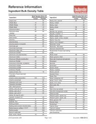
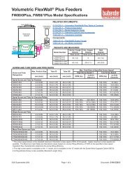
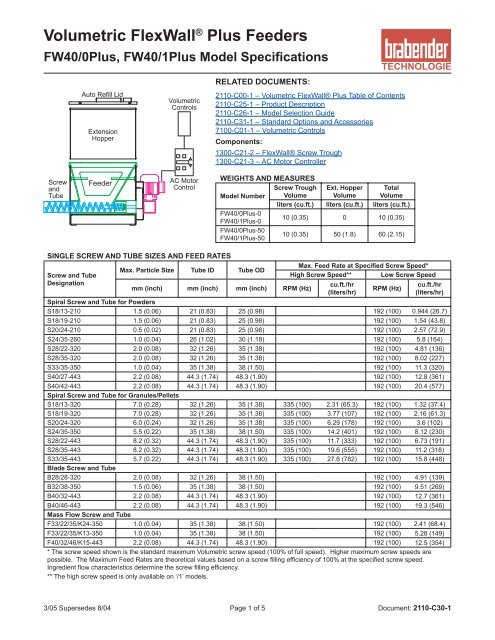
<strong>Vol</strong>umetric FlexWall ® Plus Feeders<br />
FW40/0Plus, FW40/1Plus <strong>Model</strong> <strong>Specifications</strong><br />
Screw<br />
and<br />
Tube<br />
Auto Refill Lid<br />
Extension<br />
Hopper<br />
Feeder<br />
<strong>Vol</strong>umetric<br />
Controls<br />
AC Motor<br />
Control<br />
SINGLE SCREW AND TUBE SIZES AND FEED RATES<br />
Screw and Tube<br />
Designation<br />
RELATED DOCUMENTS:<br />
2110-C00-1 – <strong>Vol</strong>umetric FlexWall® Plus Table of Contents<br />
2110-C25-1 – Product Description<br />
2110-C26-1 – <strong>Model</strong> Selection Guide<br />
2110-C31-1 – Standard Options and Accessories<br />
7100-C01-1 – <strong>Vol</strong>umetric Controls<br />
Components:<br />
Max. Particle Size Tube ID Tube OD<br />
1300-C21-2 – FlexWall® Screw Trough<br />
1300-C21-3 – AC Motor Controller<br />
WEIGHTS AND MEASURES<br />
Screw Trough Ext. Hopper Total<br />
<strong>Model</strong> Number <strong>Vol</strong>ume <strong>Vol</strong>ume <strong>Vol</strong>ume<br />
liters (cu.ft.) liters (cu.ft.) liters (cu.ft.)<br />
FW40/0Plus-0<br />
FW40/1Plus-0<br />
10 (0.35) 0 10 (0.35)<br />
FW40/0Plus-50<br />
FW40/1Plus-50<br />
10 (0.35) 50 (1.8) 60 (2.15)<br />
mm (inch) mm (inch) mm (inch) RPM (Hz)<br />
Max. Feed Rate at Specified Screw Speed*<br />
High Screw Speed** Low Screw Speed<br />
cu.ft./hr<br />
(liters/hr)<br />
RPM (Hz)<br />
cu.ft./hr<br />
(liters/hr)<br />
Spiral Screw and Tube for Powders<br />
S18/13-210 1.5 (0.06) 21 (0.83) 25 (0.98) 192 (100) 0.944 (26.7)<br />
S18/19-210 1.5 (0.06) 21 (0.83) 25 (0.98) 192 (100) 1.54 (43.8)<br />
S20/24-210 0.5 (0.02) 21 (0.83) 25 (0.98) 192 (100) 2.57 (72.9)<br />
S24/35-260 1.0 (0.04) 26 (1.02) 30 (1.18) 192 (100) 5.8 (164)<br />
S28/22-320 2.0 (0.08) 32 (1.26) 35 (1.38) 192 (100) 4.81 (136)<br />
S28/35-320 2.0 (0.08) 32 (1.26) 35 (1.38) 192 (100) 8.02 (227)<br />
S33/35-350 1.0 (0.04) 35 (1.38) 38 (1.50) 192 (100) 11.3 (320)<br />
S40/27-443 2.2 (0.08) 44.3 (1.74) 48.3 (1.90) 192 (100) 12.8 (361)<br />
S40/42-443 2.2 (0.08) 44.3 (1.74) 48.3 (1.90) 192 (100) 20.4 (577)<br />
Spiral Screw and Tube for Granules/Pellets<br />
S18/13-320 7.0 (0.28) 32 (1.26) 35 (1.38) 335 (100) 2.31 (65.3) 192 (100) 1.32 (37.4)<br />
S18/19-320 7.0 (0.28) 32 (1.26) 35 (1.38) 335 (100) 3.77 (107) 192 (100) 2.16 (61.3)<br />
S20/24-320 6.0 (0.24) 32 (1.26) 35 (1.38) 335 (100) 6.29 (178) 192 (100) 3.6 (102)<br />
S24/35-350 5.5 (0.22) 35 (1.38) 38 (1.50) 335 (100) 14.2 (401) 192 (100) 8.12 (230)<br />
S28/22-443 8.2 (0.32) 44.3 (1.74) 48.3 (1.90) 335 (100) 11.7 (333) 192 (100) 6.73 (191)<br />
S28/35-443 8.2 (0.32) 44.3 (1.74) 48.3 (1.90) 335 (100) 19.6 (555) 192 (100) 11.2 (318)<br />
S33/35-443 5.7 (0.22) 44.3 (1.74) 48.3 (1.90) 335 (100) 27.6 (782) 192 (100) 15.8 (448)<br />
Blade Screw and Tube<br />
B28/28-320 2.0 (0.08) 32 (1.26) 38 (1.50) 192 (100) 4.91 (139)<br />
B32/38-350 1.5 (0.06) 35 (1.38) 38 (1.50) 192 (100) 9.51 (269)<br />
B40/32-443 2.2 (0.08) 44.3 (1.74) 48.3 (1.90) 192 (100) 12.7 (361)<br />
B40/46-443 2.2 (0.08) 44.3 (1.74) 48.3 (1.90) 192 (100) 19.3 (546)<br />
Mass Flow Screw and Tube<br />
F33/22/35/K24-350 1.0 (0.04) 35 (1.38) 38 (1.50) 192 (100) 2.41 (68.4)<br />
F33/22/35/K13-350 1.0 (0.04) 35 (1.38) 38 (1.50) 192 (100) 5.28 (149)<br />
F40/32/46/K15-443 2.2 (0.08) 44.3 (1.74) 48.3 (1.90) 192 (100) 12.5 (354)<br />
* The screw speed shown is the standard maximum <strong>Vol</strong>umetric screw speed (100% of full speed). Higher maximum screw speeds are<br />
possible. The Maximum Feed Rates are theoretical values based on a screw filling efficiency of 100% at the specified screw speed.<br />
Ingredient flow characteristics determine the screw filling efficiency.<br />
** The high screw speed is only available on ‘/1’ models.<br />
3/05 Supersedes 8/04 Page 1 of 5 Document: 2110-C30-1
FW40/0Plus, FW40/1Plus <strong>Model</strong> <strong>Specifications</strong><br />
Conversion of FW40/0Plus or FW40/1Plus to a Twin Screw Feeder<br />
TWIN SCREW AND TUBE SIZES AND FEED RATES<br />
Screw and Tube<br />
Designation<br />
Twin Concave Screws and Tube<br />
Max. Particle Size Tube ID<br />
Twin Screw Insert<br />
Easy Change Design Option for FW40Plus Feeders<br />
FlexWall ® Plus feeders with a Swing Motor Mount have the feature of<br />
optionally switching from a single screw to a twin screw mechanism. This<br />
makes the feeder much more flexible when the ingredient being fed changes<br />
and the wiping action of a concave screw is desirable (floodable or cohesive<br />
ingredients). The twin screw drive gearbox is enclosed in the Insert housing!<br />
Change-over only requires swinging the motor out of the way, removing the<br />
single screw unit, replacing the screw tube and inserting the twin screw unit.<br />
Notes: The Twin Concave Screws are only suitable for powders. Consult<br />
factory before using the Twin Screw Insert in single screw feeders with the<br />
high screw speed.<br />
mm (inch) mm (inch) RPM (Hz)<br />
Removable with Ingredient still in the FlexWall ® Screw Trough!<br />
FlexWall ® 40 Plus feeders are available with a special Easy Change design.<br />
In this design, the outer housing, FlexWall ® screw trough, Screw and Tube<br />
can be removed as a single assembly. This way, the ingredient being<br />
fed can be changed quickly and without having to <strong>com</strong>pletely empty the<br />
ingredient from the screw trough. Or, for applications that require the screw<br />
trough, screw or tube to be cleaned, another assembly can be installed<br />
virtually eliminating downtime during the cleaning procedure!<br />
Change-over only requires releasing two latches at the back of the feeder.<br />
The assembly is then slid forward, then up. The next FlexWall ® Screw<br />
Trough, Screw and Tube assembly is then latched into place and the feeder<br />
is ready to go!<br />
Order Option ST-10.<br />
Max. Feed Rate at Specified Screw Speed*<br />
High Screw Speed** Low Screw Speed<br />
cu.ft./hr<br />
(liters/hr)<br />
RPM (Hz)<br />
cu.ft./hr<br />
(liters/hr)<br />
TC20/12-200T 0.3 (0.01) 20 (0.79) 192 (100) 0.502 (14.2)<br />
TC20/11-223T 0.7 (0.03) 22.3 (0.88) 192 (100) 0.93 (26.3)<br />
TC20/20-223T 0.7 (0.03) 22.3 (0.88) 192 (100) 1.86 (52.7)<br />
* The screw speed shown is the standard maximum <strong>Vol</strong>umetric screw speed (100% of full speed). Higher maximum screw<br />
speeds are possible. The Maximum Feed Rates are theoretical values based on a screw filling efficiency of 100% at the<br />
specified screw speed. Ingredient flow characteristics determine the screw filling efficiency.<br />
** The high screw speed is only available on ‘/1’ models. Consult factory for applications that require high speed twin screws but<br />
do not need agitation.<br />
3/05 Supersedes 8/04 Page 2 of 5 Document: 2110-C30-1
FW40/0Plus, FW40/1Plus <strong>Model</strong> <strong>Specifications</strong><br />
MATERIALS OF CONSTRUCTION<br />
FlexWall ® Flexible Screw Trough White polyurethane, resistant to abrasion, mild acids and alkaline solutions, FDA approvable <strong>com</strong>pound<br />
Feeder Housing 304SS, 2B finish inside, mirror finish outside<br />
Screw and Tube 304SS, 2B finish, electropolished<br />
Screw Drive Shaft 304SS, Polyurethane<br />
Screw Drive Shaft Seals Lip Seals (2)<br />
Extension Hopper and Lid 304SS, 2B finish inside, mirror finish outside<br />
Gaskets Neoprene<br />
MECHANICAL PROCESS CONNECTIONS<br />
Refill (on Lid) Pipe stub connection. See Mechanical Drawing for location and size.<br />
Pipe stub connection. See Mechanical Drawing for location and size. The vent allows dusty air to escape during refill<br />
Vent (on Lid) and atmospheric air to enter during feeding. Brabender offers a vent filter for pellets or non-dusty ingredients. For<br />
powders, dust collector is by others.<br />
Outlet Standard is horizontal from screw tube, optional is vertical outlet.<br />
ENVIRONMENTAL SPECIFICATIONS<br />
Temperature<br />
Ambient<br />
Ingredient<br />
Operating: 0° to 40°C (32° to 104°F), Storage: -40° to 40°C (-40° to 104°F)<br />
Continuous: 0° to 60°C (32° to 140°F), Intermittent: -20° to 60°C (-4° to 140°F)<br />
Humidity<br />
Ambient<br />
Ingredient<br />
5% to 95% (no condensation)<br />
The ingredient flow characteristics may vary with excessive humidity. The feeder must be dry when feeding.<br />
Pressure<br />
Altitude<br />
Ingredient<br />
To 10,000 feet (3,048 m)<br />
The pressure inside the feeder should be the same as outside the feeder.<br />
Vibration Normal plant vibration does not affect performance.<br />
ACCURACY<br />
Measuring Criteria Data sample time of 1 minute<br />
Feed Range 15:1 screw speed range<br />
Repeatability ± 1% to 5% depending on ingredient flow properties<br />
Linearity ± 0.5% over a screw speed range of 10:1 for each screw type<br />
Standard Options and Accessories (See Document 2110-C31-1 for Details)<br />
Extension Hoppers and Lids<br />
XH-2(A/B) Extension Hopper Lid<br />
Feeder Lid with Integrated<br />
XH-3A Safety Grate (No Extension<br />
Hopper)<br />
Feeder Lid with Inlet and Vent<br />
XH-3B Connection (No Extension<br />
Hopper)<br />
XH-4B Extension Hopper Safety Grate<br />
Flanged Inlet on Extension<br />
XH-6<br />
Hopper Lid<br />
Bag Loading Hopper with<br />
XH-7<br />
Safety Grate and Lid<br />
XH-8 Extension Hopper Handles<br />
Screw and Tube Options<br />
ST-2A Vertical Outlet<br />
ST-2B Outlet Plunger Valve<br />
ST-2C Outboard Screw Bearing<br />
ST-3 Tube Support with Guy Wire<br />
ST-5 Air Purged Seal<br />
Easy Change Screw Trough,<br />
ST-10<br />
Screw and Tube Design<br />
Additional Easy Change<br />
ST-11 Housing, Screw Trough, Screw<br />
and Tube<br />
Optional Materials of Construction<br />
MC-2B<br />
Conductive Polyurethane<br />
FlexWall ® Screw Trough<br />
MC-2C<br />
High Chemical Resistance<br />
FlexWall ® Screw Trough<br />
MC-3A 316SS Ingredient Contact Parts<br />
MC-4A Food Grade Hopper Finish<br />
MC-4B Food Grade Screw Finish<br />
MC-4C Food Grade Tube Finish<br />
Motor and Drive Options<br />
MD-2 (A-L) Screw VFD Options<br />
Flexible Connections<br />
FC-1 Flexible Inlet Connection<br />
FC-2 Flexible Vent Connection<br />
FC-3 Flexible Outlet Connection<br />
Modifications for Hazardous Areas<br />
<strong>Vol</strong>umetric Feeder Suitable<br />
XP-1(A-D)<br />
for Hazardous Areas<br />
Accessories<br />
Level Probe Connection<br />
ACC-3 (Female NPT, Probe not<br />
included.)<br />
ACC-7A Vent Dust Bag<br />
ACC-16A Feeder Lift Station<br />
Extra Parts Ordered with Feeder<br />
EP-1 Extra Screw Trough<br />
EP-2 Extra Screw<br />
EP-3 Extra Tube<br />
3/05 Supersedes 8/04 Page 3 of 5 Document: 2110-C30-1
Mechanical Drawing<br />
ITEM DESCRIPTION<br />
1 FlexWall ® Plus FW40/0Plus Feeder<br />
2 Screw Motor<br />
3 Paddles<br />
4 Extension Hopper - 50L (1.8 cu.ft.)<br />
5 Screw<br />
6 Tube<br />
7 Auto Refill Lid (Optional)<br />
8 Inlet (On Auto Refill Lid)<br />
9 Vent Dust Bag (Optional)<br />
10 Manual Refill Lid (Optional)<br />
Notes:<br />
1) All Dimensions are in Millimeters [Inches]<br />
Description ‘A’ ‘B’<br />
Standard Tube Length 100 [3.9] 285 [11.2]<br />
Standard Extended Tube Length 250 [9.8] 435 [17.1]<br />
Description ‘E’<br />
Standard Inlet Diameter 150 [5.9]<br />
Standard Larger Inlet Diameter 200 [7.9]<br />
FW40/0Plus, FW40/1Plus <strong>Model</strong> <strong>Specifications</strong><br />
Empty Feeder Weight Kg (lb)<br />
With no Extension Hopper 30 (66)<br />
With 50L (1.8 cu.ft.) Extension Hopper 48 (106)<br />
Screw Availability<br />
1) All Tubes and standard Spiral Screws are available in Standard<br />
and Standard Extended lengths from stock<br />
2) Whenever possible, use a stocked length screw and tube and<br />
move the inlet location to align the inlet and outlet of the feeder<br />
with the existing equipment<br />
3) All Spiral Screws requiring modifications, all Blade Screws and all<br />
Mass Flow Screws are special order<br />
3/05 Supersedes 8/04 Page 4 of 5 Document: 2110-C30-1<br />
E
Typical Feeder Electrical Connections<br />
FW40/0Plus, FW40/1Plus <strong>Model</strong> <strong>Specifications</strong><br />
Note: The Disconnect, Fuse Holders, Fuses, Motor Thermal Overload and wiring are by others. The AC Motor Controller is<br />
supplied loose with the feeder.<br />
115V, 1Ph<br />
AC Power<br />
Disconnect<br />
Fuse (15A)<br />
(AC Power Wiring, Wiring to the Motor,<br />
Disconnect and Fuses are not<br />
included with the feeder)<br />
FEEDER ELECTRICAL SPECIFICATIONS<br />
Screw and Paddle AC Motor<br />
Controller (A-B VFD)<br />
R/L1<br />
S/L2<br />
Head Office:<br />
6500 Kestrel Road<br />
Mississauga, Ontario<br />
Canada, L5T 1Z6<br />
AC Motor Controller (VFD)<br />
Allen-Bradley PowerFlex 40<br />
<strong>Model</strong> 22B-V2P3N104<br />
115V, Single Phase In<br />
230V, 3 Phase Out (0.5 HP)<br />
(Provides Class 10<br />
overload protection) U/T1<br />
Telephone:<br />
Toll Free:<br />
Facsimile:<br />
Email:<br />
(905) 670-2933<br />
(888) 284-4574<br />
(905) 670-2557<br />
sales@brabenderti.<strong>com</strong><br />
3/05 Supersedes 8/04 Page 5 of 5 Document: 2110-C30-1<br />
Start/<br />
Stop<br />
Input<br />
0-10V<br />
Speed<br />
Input<br />
V/T2<br />
W/T3<br />
Input Power: 115 VAC, 50/60Hz, Single Phase;<br />
Motor Output: 230 VAC, 3 Phase;<br />
Motor Control Input: 0-10V or 4-20ma;<br />
Enclosure: NEMA 1 with Keypad for Speed Control and Run/Stop<br />
Screw and Paddle Motor 1⁄2 HP (0.37 KW), 230/460 VAC, 3 Phase, TEFC<br />
AC Motor Controller (A-B VFD) Dimensions<br />
Note: The AC Motor Controller is supplied loose with the feeder.<br />
Panel Mount (Open Frame)<br />
100 (3.94)<br />
87 (3.43)<br />
5.5 (0.22)<br />
180<br />
(7.09)<br />
168<br />
(6.61)<br />
136 (5.35)<br />
Dimensions are in millimeters (inches)<br />
87.4<br />
(3.44)<br />
Shipping Weight: 2 Kg (4.9 lbs)<br />
With IP30/NEMA 1 Cover Option<br />
33.0<br />
(1.30)<br />
79.1 (3.11)<br />
64.1 (2.52)<br />
40.6 (1.60)<br />
25.6 (1.01)<br />
Motor<br />
Æ 22.2<br />
(0.87)<br />
74.3<br />
(2.93)<br />
109.9<br />
(4.33)