On the Laminar Boundary Layer Separation from the Leading edge ...
On the Laminar Boundary Layer Separation from the Leading edge ...
On the Laminar Boundary Layer Separation from the Leading edge ...

Create successful ePaper yourself
Turn your PDF publications into a flip-book with our unique Google optimized e-Paper software.
C.P. No. 220 C.P. No. 220<br />
(16,576)<br />
hR.C. Technical Report<br />
MINISTRY OF SUPPLY<br />
AERONAUTICAL RESEARCH COUNCIL<br />
CURRENT PAPERS<br />
<strong>On</strong> <strong>the</strong> <strong>Laminar</strong><br />
<strong>Boundary</strong> <strong>Layer</strong> <strong>Separation</strong><br />
<strong>from</strong> <strong>the</strong> <strong>Leading</strong> <strong>edge</strong> of a<br />
Thin Aerofoil<br />
BY<br />
P. R. Owen, BSc. and L. Klanfer, B.Sc.<br />
LONDON: HER MAJESTY’S STATIONERY OFFICE<br />
1955<br />
Price 2s. 6d. net<br />
(16.576)<br />
A.R.C. Technical Report
* I
C.P. No. 220<br />
After this paper had been discussed by <strong>the</strong> Fluid Motion sub-committee<br />
of' <strong>the</strong> Aeronautical Research Council, Dr. G. IC. Batchelor kindly sent <strong>the</strong><br />
authors a copy of a paper written by him in 1943 ('The <strong>Laminar</strong> Flow<br />
Characteristics of Three Related Aerofolls', Australian C.S.I.R. Repc& A.20)<br />
in which he described observations of <strong>the</strong> 1amina.r bowdairy layer separation<br />
<strong>from</strong> an aerofoil and its subsequent reattachmnt as a turbulent layer.<br />
He, too, conjectured that 7,/S* or U,Z/v would be a fumixon of (R$)s,<br />
although all his results were confined to what we have called 'short bubbles'.<br />
Batchelor's measumments, which relate to separation <strong>from</strong> a point<br />
tomm3.s <strong>the</strong> rear of <strong>the</strong> aerof'oll at smallinc~dence, are not inconsmtent<br />
mth Figures 2 and 3 of this paper, and are shorm in <strong>the</strong> Table helm.<br />
a/s; (RE?‘)~<br />
4Q 1060<br />
39<br />
1200<br />
43 1680<br />
54 290<br />
34<br />
21<br />
6<br />
2910<br />
3360<br />
3760
RCYALAIRCRAFTBTABLISHMEIiT.<br />
"<strong>On</strong> <strong>the</strong> leminar boundary layer separation<br />
<strong>from</strong> <strong>the</strong> leading <strong>edge</strong> of a thin aerofoil"<br />
I?. B. Orren, a.sc.<br />
and<br />
L. KLsnfer, a.sc.<br />
C.P. No. 2x)<br />
Report No. Hero 2508<br />
October, 1953<br />
Low sped wind tunnel tests have shown that Aen a laminar boundery<br />
layer separates <strong>from</strong> <strong>the</strong> leading <strong>edge</strong> of a thin aerofoil at incidence <strong>the</strong><br />
flow often becomes attached to tho surface again siane distance domnstresm.<br />
The region of sepsratta3 flovr is called a bubble and its chordwise dimension<br />
may very fYom a minute fraction of <strong>the</strong> chord to a length ccmparable uith<br />
<strong>the</strong> chord, depending on incidence, Reynolds number and type of aerofoil<br />
section. In this respect, a marked contrast between <strong>the</strong> lengths of bubble<br />
on <strong>the</strong> N.fI.C.lr. 63-009 and 64-006 sections was found in tests at Langley<br />
Field.<br />
I-i, is suggested that <strong>the</strong> length of bubble (more accurately, its order<br />
of magnitude compared rijth <strong>the</strong> thickness of <strong>the</strong> laminar boundary layer at<br />
separation) depends primarily on <strong>the</strong> Reynolds number (Rb"). based on <strong>the</strong><br />
displacement thictiess at <strong>the</strong> separation point; if (Rg )s exceeds 400-500,<br />
<strong>the</strong> bubble is short: if less than this band of values, <strong>the</strong> bubble may be<br />
long. OW) s in turn deportds on <strong>the</strong> distance of <strong>the</strong> velocity peak on <strong>the</strong><br />
upper surface of <strong>the</strong> aerofoil <strong>from</strong> <strong>the</strong> fron t stagnation point end it is<br />
inferred that, at a givenReynolds number based on <strong>the</strong> chord, a long<br />
bubble is more likely to occur when <strong>the</strong> velocity peak is close to <strong>the</strong><br />
stagnation point: but a scale effect, such as to cause <strong>the</strong> bubble to<br />
change <strong>from</strong> long to short as <strong>the</strong> Reynolds number is increased beyond a<br />
critical value, can also be expected<br />
These observations are used to comment on certain peculiarities in<br />
<strong>the</strong> stalling behaviour of thin sweptbackmings.
1 1iltrod.uction<br />
2 Some eqerdmcntal results<br />
2.1 Definitions of long and short bubbles<br />
3 The mechanism of flow reattachment<br />
4 Analysis of experimental data<br />
4.1 Variation in <strong>the</strong> length of bubble mitnReyflolds<br />
number at separation<br />
5 Discussion<br />
6 Future dweZopments<br />
7 Conclusions<br />
References<br />
LIST OF TA&Es<br />
Length of bubblqkng chord<br />
Length of bubble/displacemtxt thiolaeso<br />
Comparison between <strong>the</strong> observed and estimated<br />
positions of <strong>the</strong> laminar separation point<br />
Relation between type of bubble and boundary layer<br />
Reynoldsnunberatseparation<br />
Length of bubble and boundary layer<br />
Reynolds number at sep?cration<br />
LIST or' ILLUSTRhT10iE<br />
L%t curves for sections of 6$ and 9 thictiess/chord<br />
ratio<br />
Variation of lagth of separated tin region with<br />
bound.arylaywReynoldsn~bes at <strong>the</strong> separatLonpotit<br />
Us&<br />
Variation of T wxth boundary layer Reynolds number<br />
at <strong>the</strong> separation point<br />
Relation betweci? velodty at separation and maximum<br />
velocity<br />
Maximum lift of N.A.C.A. cam'ocred aerofoil sections<br />
-2-<br />
P*<br />
3<br />
3<br />
4<br />
5<br />
6<br />
7<br />
9<br />
11<br />
II<br />
13<br />
Table<br />
I<br />
II<br />
III<br />
Iv<br />
v<br />
VI<br />
Figure<br />
1<br />
2<br />
3<br />
4<br />
5
1 ~troduction<br />
It is well known that at low subsonic speeds, <strong>the</strong> laminar boundary<br />
layer on a thin aerofoil separates <strong>from</strong> <strong>the</strong> upper surface at a point VWY<br />
near <strong>the</strong> lea&q &ge if <strong>the</strong> incidence is sufficiently high. The cause,<br />
obviously enough, is <strong>the</strong> severe adverse pressure grtiient that develops<br />
5.n <strong>the</strong> neighbourho& of <strong>the</strong> sharply curved nose. Until recently <strong>the</strong><br />
phenomenon was not considered to have much practical aeronautical signi-<br />
ficance, since wings in ootmon use were of such thickness (groatcr than<br />
0.1 chord) that <strong>the</strong> stall usually began near <strong>the</strong> trai.Llng <strong>edge</strong> in <strong>the</strong><br />
form of a turbulent boundary layer separation. But wings - for military<br />
arcraft at least - have now to be designed for satisfactory operation at<br />
high Mach numbers, with <strong>the</strong> inevitable trend towards sinall thiclnoss/ohord<br />
ratios, an6 laminar separation <strong>from</strong> <strong>the</strong> forward parts of <strong>the</strong> profile has<br />
emerged as a ssi-ious practical problem.<br />
At largeReynolds numbers, in excess of IO6 based on <strong>the</strong> chord, and<br />
with wings having a finite, but small, nose radius of curvature <strong>the</strong><br />
separated flow generally becomes attached to <strong>the</strong> surface again as a twbu-<br />
lent boundary layer, and <strong>the</strong> region between <strong>the</strong> points of scp3satton and<br />
reattachment is often graphically referrod to as a "bubble". The extent<br />
of <strong>the</strong> bubble on two-dimensional wings has been found in,ezqzriment to<br />
vary <strong>from</strong> a tiny proportion of <strong>the</strong> chord - less than 0.1% - to something<br />
comparable with <strong>the</strong> chord length, and this paper is conowned. rjith <strong>the</strong><br />
psrtioular problem of explaining <strong>the</strong> mechanism that controls <strong>the</strong> length<br />
of bubble.<br />
2 Some experimental results<br />
The behaviour of <strong>the</strong> bubble as <strong>the</strong> incidence is altered has a porn<br />
ful influence on <strong>the</strong> stalling characteristics of <strong>the</strong> wing; in particular,<br />
<strong>the</strong> contrast betneen 3. wing nith a smsll bubble end one ~6th an extensive<br />
bubble has been demonstrated in some remarkably detailed ciind. tunnel<br />
experiments made by U.A.C.A.',~. Two symwtrioal acrofoils vrere tested,<br />
one of N.A.C.A. 64-co6 and <strong>the</strong> o<strong>the</strong>r of X.A.C.A. 63-009 section; in both<br />
cams <strong>the</strong> Reynolds number was 5.8 x 10⁶. At small incidence.? it was<br />
found that a minute bubble developed. near <strong>the</strong> lead- <strong>edge</strong>s of both Gngs.<br />
The bubble on <strong>the</strong> t-or wiig rapidly enlarged as <strong>the</strong> incidence exceed&.<br />
5O and with fur<strong>the</strong>r increase of incidence became progrossiv&y longer<br />
until it extended over <strong>the</strong> entire chord, at which stage <strong>the</strong> wing could be<br />
regarded as coqletely stalled. <strong>On</strong> <strong>the</strong> o<strong>the</strong>r hand, <strong>the</strong>re eras little<br />
change in <strong>the</strong> length of blbble on <strong>the</strong> thicker wang w to a certain moi-<br />
dence; beyond this, <strong>the</strong> bubble suddenly "burst", causing <strong>the</strong> aerofoil to<br />
stall abruptly, This "burstmng" 0~1 be interpreted as a failure of <strong>the</strong><br />
separated flow to reattach itself to <strong>the</strong> surface. The lengths of bubble<br />
on <strong>the</strong> two wings are compared in <strong>the</strong> Table below.<br />
TAl?LEI<br />
Length of bubble/wing chord<br />
Incidence Length of bubble/(wvlg chord)<br />
(degrees) ' 64-006 section 63-009 section<br />
5 0.08 0.0052<br />
6 0.23 0.0048<br />
87 0.56 0.40 0.0034 0.0022<br />
9 Upper surface stalled Upper surface stalled<br />
-3-
The sequgnce of events described above can be traced. in <strong>the</strong> lift<br />
curves which sre~e in Fig.1. The lift on <strong>the</strong> 6,: thick section,<br />
shown m Fig.1 (a), rises l&aar.ly with incidence as far BS rougM.y 5O<br />
when a rapid chzmge, amounting practically to a discontinuity, ocours.<br />
This stage corresponds to <strong>the</strong> sudden enlargem~t of <strong>the</strong> region of<br />
separated flow. For incidences greater than 50 <strong>the</strong> lift rises aga-b, but<br />
with a reduced gradient attributable to <strong>the</strong> progressive spreading of <strong>the</strong><br />
separation bubble along <strong>the</strong> wper surface. In <strong>the</strong> neighbourhood of 5'<br />
incidence <strong>the</strong> aorrmstream end of <strong>the</strong> bubble reaches <strong>the</strong> trailing <strong>edge</strong>,<br />
resulting in a gentle stall.* The lift curve for <strong>the</strong> 9,; thick section is<br />
markedly different. It is quite straight up to an incidence of 90; at<br />
<strong>the</strong> stall, <strong>the</strong> lift fsLL3.s catastrophically owing to <strong>the</strong> violent disru&i.on<br />
of <strong>the</strong> bubble.<br />
2.1 Definitions of "lo&' and. "six~4Y bubbles<br />
A<br />
The bubble on <strong>the</strong> thinner w5ng will be seen <strong>from</strong> Table I to be f'rom<br />
10 to 100 times longer <strong>the</strong>n that on <strong>the</strong> thicker wing, in terms of <strong>the</strong><br />
ohora. While this description serves to distinguish between long and<br />
short bubbles on <strong>the</strong>se psrticular se&tins, it is not convenient f9r a<br />
general discussion; for this purpose? it is preferable to relate <strong>the</strong> size<br />
of bubble to scme length characteristic of <strong>the</strong> boundsry layer at <strong>the</strong> point<br />
of separation, and we shall here choose <strong>the</strong> displacement thickness.<br />
Writing 8*s for <strong>the</strong> displacement thictiess at separation, which can be<br />
oalculated by <strong>the</strong> methods referred to in Seotion 4, and G for <strong>the</strong> length<br />
of bubble, some typical ratios of e/$,*s for <strong>the</strong> two N.A.C.A. aerofoils<br />
are shown in <strong>the</strong> Table below.<br />
TAELSII<br />
Length of bubble{Jdisplacement thickness<br />
Incidence<br />
(degrees)<br />
i<br />
&/Ps<br />
64-006 Section 63-009 Section<br />
ytg<br />
i2:890<br />
The figures in Table II suggest <strong>the</strong> fOllOWbg definitions:<br />
short bubble; G*, - 102<br />
long bubble; G/6", - ldt<br />
It wjll be demonstrated later that <strong>the</strong>se defvlitions have a greater<br />
generality than <strong>the</strong> few values given in Table II might imply.<br />
* The different re ines of flow czn also be related to <strong>the</strong> behaviour of <strong>the</strong><br />
centre of pressure 5 . Between zero end 5" <strong>the</strong> centre ofpressure remains<br />
fixed a short distance aft of <strong>the</strong> $-chord point on <strong>the</strong> aerofoil. As <strong>the</strong><br />
~c&atmce is increased beyond 5O <strong>the</strong> centre of pressure at first mwcs<br />
slightly forward. <strong>the</strong>n, at about 60, moves aft; <strong>the</strong> aft movaent is<br />
especially rapia as <strong>the</strong> stall is xgproached. These variations in catre of<br />
pressure position can bc explained qualitatively by regarding <strong>the</strong> bubbles<br />
as a region of quiescent flow in which <strong>the</strong> pressure is nearly constant.<br />
Thus, as <strong>the</strong> bubble grows, <strong>the</strong> pressure on <strong>the</strong> wing becumcs more uniformly<br />
distributed along <strong>the</strong> chord. Initially, this happens near <strong>the</strong> leading <strong>edge</strong>,<br />
gixing rise to a forifard centre of pressure movement: subsequently it<br />
extends over a large part of <strong>the</strong> chord, so redistributing tie lift as to<br />
cause <strong>the</strong> catre of pressure to move af%,<br />
-4-<br />
i:<br />
46
3<br />
The mechanism of flow reattachment<br />
The contrasttig behaviour of <strong>the</strong> 6,: and 9,: thick aerofoils described<br />
in <strong>the</strong> previous Section brings out quite plainly <strong>the</strong> importance of <strong>the</strong><br />
lamjnsr separation bubble and <strong>the</strong> way i' LI spreads with change of inciaence.<br />
The questions wh5ch naturally follow this observation are: (a) can we<br />
. , prdict frcm some property of <strong>the</strong> aerofoil, such as <strong>the</strong> pressure distri-<br />
bution over its upper surface, v&e<strong>the</strong>r <strong>the</strong> bubble will be long or skort?;<br />
(b) can it be assuned that <strong>the</strong> type of bubble found at wind tunnel<br />
Rtynolds nmbers will persist at full scale? In many respects <strong>the</strong> second<br />
cpestion is <strong>the</strong> more important.<br />
Before attempting to answer <strong>the</strong>se questions we mLst construct some<br />
hypo<strong>the</strong>sis concernjng <strong>the</strong> reattachment of <strong>the</strong> separated flow to <strong>the</strong> SWface<br />
of <strong>the</strong> wing, and <strong>the</strong> rapidity with which it occurs. For <strong>the</strong> mechanism<br />
of reattachment, <strong>the</strong>re is ample evidence* to shcx that transition to<br />
turbulence takes place in <strong>the</strong> bubble snd <strong>the</strong> subsequent turbulent mixing<br />
%%th <strong>the</strong> main stream is sufficient to re-energise <strong>the</strong> separated flow,<br />
causing it to return to <strong>the</strong> surface and re-form a (turbulent) boundary<br />
leer. Clearly, <strong>the</strong> proximity of <strong>the</strong> reattachment point to <strong>the</strong> separation<br />
point will depend on hole quicldy transition sets in; in turn, this zill<br />
depend on <strong>the</strong> stability of <strong>the</strong> 1amina.r flow tiediately dovmstream of <strong>the</strong><br />
separation point, which can be described. by <strong>the</strong> boundary layer velocity<br />
profile <strong>the</strong>re. Not;, <strong>the</strong> velocity distribution over <strong>the</strong> upper surface of<br />
a thin wing at incidence, near its leading <strong>edge</strong>, can be represented<br />
roughly by two straight lines; as <strong>the</strong> slopes of tic lines and <strong>the</strong> maximum<br />
velocity are varied, <strong>the</strong> boundary layer thickness at <strong>the</strong> separation<br />
point alters, but <strong>the</strong> velocity profiles at separation rasnain simzil.ar.**<br />
We may <strong>the</strong>refore describe <strong>the</strong> shape and scale of <strong>the</strong> bo~mdary layer at<br />
<strong>the</strong> separation point by a single par-ameter &fined. by<br />
where Us is <strong>the</strong> main stream velocity outside <strong>the</strong> boi;ndary layer and<br />
@S is <strong>the</strong> displacement thickness, both measured at separation. Accord<strong>the</strong><br />
initial stability of <strong>the</strong> separated flow will be a function of<br />
ggy;.<br />
Prom our knowl<strong>edge</strong> of <strong>the</strong> behaviour of laminsr wakes, to which <strong>the</strong><br />
separated flow bears a certain resemblance, we can postulate 3 critical<br />
Reynolds nmbc.r above which <strong>the</strong> flow is unstable. when instability sets<br />
in - It will be of <strong>the</strong> dynamic twe and <strong>the</strong>reforo comparatively violent -<br />
transition to turbulence occurs neaS tc <strong>the</strong> separation point; "n6s.P in<br />
this sense can be t::ken to mean within a few hundred displacement thick-<br />
nesses. <strong>On</strong> <strong>the</strong> o<strong>the</strong>r hand, when (R(6")s is less than <strong>the</strong> critical value,<br />
<strong>the</strong> separated flow at f3rst remains laminar for scme distance downstream<br />
of <strong>the</strong> separation point and <strong>the</strong>n, as <strong>the</strong> shape of its velocity profile<br />
changes, instability develops, eventually leading to turbulence. In this<br />
case <strong>the</strong> distance between <strong>the</strong> sc2aration and. transition points may be<br />
several thousand displacement thicknesses.<br />
Of course, <strong>the</strong> condition for transition to turbulence is not suf-<br />
fxient to determine exactly where <strong>the</strong> Klcw becomes reattached to <strong>the</strong><br />
4 Especially in ref.8 whtz?e hot-wire explorations of <strong>the</strong> region of<br />
separated flar are descrzbed.<br />
** This is most easily demonstrated by Eowarth's method3 of calculating a<br />
boundary layer flow subjected to a constant adverse velocity gradLent.<br />
-5-
surface or, indeed, whe<strong>the</strong>r reattachment occurs at all: pie simply postu-<br />
late transition as a necessary condition.* For example, if <strong>the</strong> aerofoil<br />
incid.enoe is large enough, separation persists in spite of trS.nSiti<strong>On</strong>.<br />
Clearly <strong>the</strong>refore, <strong>the</strong> geometry of <strong>the</strong> aesofoil must be taka into account<br />
if a precise description of <strong>the</strong> reattachment phehencon is to be obtained..**<br />
However, if we approach <strong>the</strong> problem less delicately, supposing that re-<br />
attachment has ocourred, and merely attempt to distinguish between <strong>the</strong><br />
conditions for long and short bubbles, <strong>the</strong> elementary criterion basd on<br />
should be adequate. <strong>On</strong> this basis, <strong>the</strong> following hypo<strong>the</strong>sis is<br />
<strong>the</strong> bubble of separated flow will be long or sdrt according<br />
is less than or greater than a certain critical value.<br />
4<br />
Analysis of experim3ntal data<br />
irjhen a laminsr boundary layer separates <strong>from</strong> <strong>the</strong> lesding <strong>edge</strong> of an<br />
aerofoil, its thiclaess is small and., in general, (RE")~ cannot be deduced.<br />
with sufficient accuraoy <strong>from</strong> measurements of <strong>the</strong> boundary layer<br />
velocity profile; for this reason it is preferable to oalcul;~;*)s.<br />
Two methods were used to calculate <strong>the</strong> growth of <strong>the</strong> laminar<br />
layer, given <strong>the</strong> measured chordwise velocity distribution in <strong>the</strong> main<br />
str Sam; <strong>the</strong> first was to apply <strong>the</strong> Pohlhausen met d in <strong>the</strong> region of<br />
increasing velocity, joining on to Hcwsrth's method "5; in <strong>the</strong> subsequent<br />
region of deoreasing velocity: <strong>the</strong> second, and simpler, method was that<br />
given by Thwaitedt. The lx0 methods gave very nearly <strong>the</strong> same values of<br />
momentum thickness, displacement thickness and skin fYiction ?n <strong>the</strong> rangqs<br />
of both favourable and unfavourable velocity gradient, as well as <strong>the</strong><br />
location of <strong>the</strong> point of separation. 'Smce Thwaites' method is <strong>the</strong><br />
easier, it was used to calculate (R@)s for o<strong>the</strong>r aerofoils. A comparison<br />
between <strong>the</strong> observed. and estimated positions of <strong>the</strong> leminar sepsqation<br />
point in a few typical cases is made in Table III.<br />
I<br />
l%ETJE III<br />
Comparison between <strong>the</strong> observed and estimated positions<br />
of <strong>the</strong> laminar separation point<br />
Incidenoe<br />
TWA 63-009 section<br />
t<br />
Obswved<br />
I<br />
xr4c<br />
Calculated<br />
Thwaites Pohlb.ausen-Howarth<br />
4" 0.021 0.025 0.021<br />
6O 0.0215 0.022 0.022<br />
a0 0.025 0.024<br />
NACA 63-012 section<br />
IO.80 0.041 0.041<br />
xs is <strong>the</strong> distance of <strong>the</strong> separation point <strong>from</strong> <strong>the</strong> front stagnation<br />
point, measured parallel to <strong>the</strong> aerofoil surface: c is <strong>the</strong> chord.<br />
*. But only for <strong>the</strong> particular problem under discussion; at high subsonic<br />
or supersonic speeds for example, <strong>the</strong> mechanism of rcattacbment is<br />
different and <strong>the</strong> fl.owmayreJnainlsminar.<br />
r'g It is evident that <strong>the</strong> slope and curvature of <strong>the</strong> aerofoil profile at<br />
<strong>the</strong> separation point are jmportsnt in this respect.<br />
-6-
Observations of regions of larmnar separation are not confined to<br />
thin aerofo1ls; data are also available on <strong>the</strong> laminsr separation that<br />
occurs downstream of <strong>the</strong> mininum pressure point on moderately thick aerofoils,8,11<br />
again follcwed by turbulent reattachment.q O<strong>the</strong>r interesting<br />
lata are provided by Gadd aid Holdes's observations at a Nachnwnbw of<br />
2.0 of <strong>the</strong> interaction bctwcen an oblique shock wsve and a laminar boundary<br />
layer on a flat platd. It wa.s fcund that at certain9oync;lds number<br />
separation ocourrcd upstream of tho incident shock, f'ollcwed by transition<br />
and rsattachment. The region in which transition took place zp2ezred to<br />
coincide with a k$?k in <strong>the</strong> pressure distribution along <strong>the</strong> surface of <strong>the</strong><br />
Idate and could <strong>the</strong>refore be aproximitely defined by <strong>the</strong> pressure measu-nemen&.<br />
In this way, <strong>the</strong> authors mere able to deduce <strong>the</strong> distance betmm<br />
<strong>the</strong> points of separation and transition (roughly equal to <strong>the</strong> length 4<br />
used here); <strong>the</strong>y conclude3 that this distance was a function of <strong>the</strong><br />
Reynolds number and did not depend on shock str-xgth. &rt::x experunewd<br />
showed that it was not greatly affected by change in Mach number; in fact,<br />
ZXI increase in Mach nmber f?.c-cm 1.5 to 4.0 only altered 8/S', by a<br />
factor ef 2. It nil1 be shown later that <strong>the</strong> values of 616 ‘s d.e&xe<<br />
<strong>from</strong> <strong>the</strong>se experiments are of 'dne same order of magnitude as those obtaind<br />
<strong>from</strong> experiments on aerofoils at low speeds within <strong>the</strong> same range of (RsL)s.<br />
4.1 Variation in <strong>the</strong> length of bubble withReynolds number at sewwation<br />
Values of 4/&s vilth corresponding valuee of (R&*)s are presented<br />
in Table VI, at <strong>the</strong> end. of <strong>the</strong> paper, for a numbes of aerofoils 1,2,7,8,10,11<br />
and for <strong>the</strong> shook wave experiments of Gadd an6 Holder5,6. To distinguish<br />
between experimental and caloulated quantities: 8 is <strong>the</strong> length of bubble<br />
deduced <strong>from</strong> <strong>the</strong> experimentel obsmations, 6's is <strong>the</strong> calculated dis-<br />
placemat thickness at sepaz-ation (for which <strong>the</strong> measured d5stribut%on of<br />
velocity outside <strong>the</strong> boundary layer is used), and in tile Reynolds nwnbw<br />
(W) s , equal to Us6*s/v, Us is <strong>the</strong> nbsezved. velocity Just outsxle <strong>the</strong><br />
boundary layer at <strong>the</strong> separation pomt.<br />
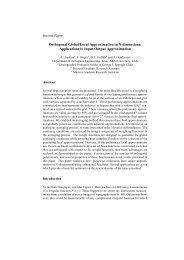
Using <strong>the</strong> tabulated results, log10 &/K's is plotted against (Rg')s<br />
in Fig.2. The points in this figure fall strikingly into two djstinot<br />
groups; one group for (I$*) s greater than 850, conta?ning Gadd 2nd<br />
Holder's supersonic measurements, clusters about <strong>the</strong> line log.10 &/Ps = 2,<br />
although <strong>the</strong>re is a terdency fur &/6"s to fall slightly with increzdng<br />
Reynolds number. The o<strong>the</strong>r grow, (Rh*'), less than 530, lies between<br />
loglo4/6*, = 3 ma log10 e/&as = 5. This behaviour is consistent v&h<br />
<strong>the</strong> hypo<strong>the</strong>sis advaxced in Section 3, znd suggests that SI critical Reynolds<br />
nmber, or band ofR@ynolds numbers, exists in <strong>the</strong> region 400-800, above<br />
which &/6*s is of order q02 - short bubbles - and below which 8/Ps is<br />
more sensitive to chances inReynolds number and may attair values of ordx<br />
104 - long bubbles. The abruptness of <strong>the</strong> change in bubble length as <strong>the</strong><br />
Reynolds number passes through <strong>the</strong> critical region can be betty appreciated<br />
<strong>from</strong> Pig.3 where U&/Y is plotted against (Rs*)~.<br />
Some fur<strong>the</strong>r experinental evidence of a critical Reynolds nmber was<br />
brought to 0~1 attention by Sir Xelvill Jones. Hc set his underpraciuate<br />
stu&&s at Cambridge University a lnborotory example which consisted of<br />
observing <strong>the</strong> change in <strong>the</strong> character of <strong>the</strong> flow about a thick aerofoil<br />
at zero incidence with change in Reynolds number or tunnel Mndspeed. A><br />
low Reynolds numbers a complete laminzr scpwation ocmmed. <strong>from</strong> <strong>the</strong> rear<br />
part of <strong>the</strong> acrofoil surface, <strong>the</strong>n, as <strong>the</strong> Reynolds number was mcrensed,<br />
transition amenrcd in <strong>the</strong> separated wake; st a sufficiently high Reynolds<br />
' Par such aerofotis, <strong>the</strong> reattached boundary layer is not invsrinbLy tur-<br />
bulent, but for <strong>the</strong> purpose of <strong>the</strong> present analysis we shall only refer<br />
to experiments in which transition was known to occur 5.n <strong>the</strong> separated<br />
flow.<br />
-7-
number, <strong>the</strong> flon became reattached as a turbulent bow layer. The<br />
gradual approach of <strong>the</strong> transition point in <strong>the</strong> seperrted layer to <strong>the</strong><br />
separation point is enslogous to <strong>the</strong> change <strong>from</strong> a long bubble to a short<br />
bubble in <strong>the</strong> case when separation is only transient. The Reynolds nmber<br />
at which separation was suppressed in <strong>the</strong> Cambridge experiment may <strong>the</strong>refore<br />
be ocDnpared with <strong>the</strong> critical Reynolds number suggested. by Figs.2 and<br />
3. <strong>On</strong> ane&sis", it wes found t&t <strong>the</strong> critical value of (R$)s was 350,<br />
which is oertainLy of <strong>the</strong> same order of magnitude as that inferred fYom<br />
Figs.2 ml 3,**<br />
Clearly, z+ore data are required to make t& wnolusions drewn <strong>from</strong><br />
Figs.2 and 3 really oonvinc3ng: in particular, fur<strong>the</strong>r observations on<br />
aerofoils with long bubbles are needed - <strong>the</strong> few points for Reynolds<br />
numbers less than 5cO relate cmly to <strong>the</strong> 1i.A.C.A. 64-006 section and, with<br />
doubtful aoomacy, to a double wdge section."'" <strong>On</strong> <strong>the</strong> o<strong>the</strong>r hand,<br />
fur<strong>the</strong>r weight can be given to <strong>the</strong> conclusions by some more results on <strong>the</strong><br />
N.A.C.A. 64-006 aerofoil. In Figs.2 and 3 only points relating to long<br />
bubbles are shown, but it wi?l be recalled. <strong>from</strong> <strong>the</strong> description given in<br />
Section 2 that short bubbles were detected on this aerofoil at incidenoes<br />
1~s than 5O, <strong>the</strong> chenge <strong>from</strong> one type of bubble to <strong>the</strong> o<strong>the</strong>r OOOUZT~~~<br />
Caloulations made for inoidences of 3O, b” and l++O led to<br />
~~~e~%~~~* ) 5 which are compared in Table IV with ccu-rosponding<br />
values at. higher incidenoea.*"i+<br />
l!AmEIv<br />
Relation between tVpe of bubble and boundary I.=<br />
Reynolds number at separation_<br />
Incidence degrees hj")s<br />
3 480<br />
$2 ;z<br />
Type of bubble<br />
short<br />
short<br />
short<br />
3 400 310 10% low<br />
long<br />
87 34:: long<br />
long<br />
9 long<br />
* The authors are indebted to Nr. E.C. Meskell for <strong>the</strong> experimentsl<br />
observations recorded in his laboratory note-book.<br />
** It may be noted that <strong>the</strong> Mnd tunnel in which <strong>the</strong> experiments were<br />
made had a high turbulence intensity, and so might be expected to en-<br />
courage an early transition; this o~uld explain why (Rb*)s.mit.<br />
deduoed <strong>from</strong> <strong>the</strong> Cambridge experiment is slightly lower than <strong>the</strong> bend<br />
of values in Figs.2 and 3. However, differences of this order are not<br />
siyifkant since we cannot hope to define more than a roughmagnitude<br />
Of (Rg*)s.orit.<br />
*** It wes necessary to guess part of <strong>the</strong> velocity distribution new <strong>the</strong><br />
leading <strong>edge</strong> of <strong>the</strong> double-w<strong>edge</strong> so&&on in order to calculate (R$)s.<br />
**** It is clear A-am <strong>the</strong> pressure distributions given in ref.2 that short<br />
bubbles were present at rUoidenocs less <strong>the</strong>n 5O although no measure-<br />
ments of <strong>the</strong> lengths of <strong>the</strong>se short bubbles wae reported.<br />
-a-
The results shown in Table IV indicate clearly a change <strong>from</strong> a short<br />
bubble to a long bubble as (IQ*)s falls below 400. This observation<br />
helps to na-row <strong>the</strong> ta-d of criticalX!eynolds naber to roughly 400-500,<br />
which is of <strong>the</strong> order of magnitude found by Lirure for trznsitim to tur-<br />
tulence in <strong>the</strong> layer of separated flow behind a circuJar cyltitier9.<br />
5<br />
Discussion<br />
The criterion emerguy <strong>from</strong> <strong>the</strong> analysis of Section 4 is that <strong>the</strong><br />
separation b=bble will be short if (35') exceeds a value in <strong>the</strong> neighbourhood<br />
of 400-500 and will be long if && lies below this band of<br />
values, It would, of course, be desirable to construct a rule which was<br />
related. ma-e obviously to <strong>the</strong> properties of <strong>the</strong> aerofoil section, but in<br />
general it is not possible GO 130 this accurately sines (Rg")s depends<br />
critically on <strong>the</strong> velocity distribution new <strong>the</strong> leading e&e, rrhich in<br />
turn is affected by <strong>the</strong> bubble. As a very rough approximation, howver,<br />
<strong>the</strong> velocity distribution over <strong>the</strong> front p;ir C of <strong>the</strong> upper surface of <strong>the</strong><br />
aerof'oil may be rqresented by two s$rnight lines. It <strong>the</strong>n tans out that<br />
&&"), is proportional to (U&v)5 , where Urn is <strong>the</strong> peak velocity<br />
and xm its diswnce fro?x <strong>the</strong> fYont stagnation point. The factor of<br />
proportionality is a flrnction only of <strong>the</strong> ratio of <strong>the</strong> slqes of <strong>the</strong> tw<br />
lines an3 may be treated as nearly constant for <strong>the</strong> class of velocity<br />
distributions typicnl of thin nerofoils at incidence." '"his is to some<br />
extent borne out by <strong>the</strong> values of (ZL$)s for tne N.A.C.A<br />
64-006 and. G3-009 arofoil sections shown in Table V.<br />
t-<br />
c<br />
Aerofoil<br />
NAG. 6l&.A006<br />
1<br />
w&CA 63-009<br />
TAELEV<br />
Incidence degees (Q*)s,j,<br />
I<br />
5<br />
/: %%<br />
) ‘2<br />
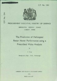
Ano<strong>the</strong>r interesting result of <strong>the</strong> tvo-lme approximation is that U&m<br />
also is a function only of <strong>the</strong> ratio of <strong>the</strong> sloges and again might be<br />
taken as roughly con&an? for thin azafo2ss; that
U, are plotted. The ratio U&m <strong>from</strong> Fig.4 is 0.95; a similar<br />
analysis in ref.1 gave Us/Urn = 0.94.<br />
The relation b&Teen (Rj*)s and (Um]Fdv)*, although of trivial<br />
<strong>the</strong>oretical jnterest, gives a useful clue to <strong>the</strong> connection betmeen<br />
bubble length and type of aerofoil, stioe it is found <strong>from</strong> experjment<br />
that onoe a bubble forms <strong>the</strong> variation in LJ&o <strong>from</strong> one aerofoil to<br />
ano<strong>the</strong>r (or, on % given aerofoil, <strong>from</strong> cne inoiiienoe to ula<strong>the</strong>r) is<br />
smtiier than <strong>the</strong> variation in z&o. Accordingly, at a givenReynolds<br />
number (based now on aerofoil chord), long bubbles are associated with o<br />
forward position of <strong>the</strong> suction peak, which oorTespond.s to sms.L nose<br />
radius of cunrature end thickness/chord ratio, or high incidence. This<br />
observaticn is supported by <strong>the</strong> analysis of Q.,ms.x in terms of nose<br />
radius of curvature (or, tiat is almost <strong>the</strong> same, <strong>the</strong> ratio of thiohess<br />
at 0.05 chord. to <strong>the</strong> chord, 7 0.05) w2.de by EiLthopp~2 who constructed<br />
o-es of <strong>the</strong> measured CL= for a nmber of aerofoils against '~0.05.<br />
These c-es, in most instances, consisted of a flat portion for small<br />
values of ~0.05 (see Fig.5, copied <strong>from</strong> ref.12) followed by a steep<br />
increase in CLmax with ~0.05, a flat maxtim, end ultimately a gradusl.<br />
fall in N-. The ohenge <strong>from</strong> <strong>the</strong> initially flat part of <strong>the</strong> curve to<br />
<strong>the</strong> rising part was abrupt and csn be interpreted acoording to our present<br />
arpent as a change <strong>from</strong> a long bubble to a short bubble on <strong>the</strong> aerofoil<br />
surface at incidenoes near to tnat of <strong>the</strong> stall.'<br />
The simple association betmeenlength of bubble end position of <strong>the</strong><br />
suction peak can also be used to explain <strong>the</strong> stnlling behaviour 3f certain<br />
sweptback wings. For instance, it is sometimes found <strong>from</strong>windtunnol<br />
tests on thin wings at Reynolds numbers of <strong>the</strong> order of 106 that lamjnsr<br />
separation OCOUTS <strong>from</strong> <strong>the</strong> leading <strong>edge</strong> followed by reattachmd, just as<br />
with two-dimensional aerofoils: but, in contrast to <strong>the</strong> %o-dimensional<br />
case, <strong>the</strong> type of separation bubble is not constold across <strong>the</strong> span. over<br />
<strong>the</strong> inboard parts of <strong>the</strong> leading <strong>edge</strong> <strong>the</strong> bubble 1s short, whereas over<br />
*he outboard parts it is long; a trailing vortex sheet, called by<br />
Kuchm~3 a part-spen vortex sheet, sepsrates <strong>the</strong> two flow regimes. If<br />
we coneider only <strong>the</strong> flow component normal to <strong>the</strong> leading <strong>edge</strong>, <strong>the</strong> ohsnge<br />
in <strong>the</strong> type of bubble can be explained by means of <strong>the</strong> spenwisc variation<br />
in <strong>the</strong> flow near <strong>the</strong> leading <strong>edge</strong>: because, at a given incidence, <strong>the</strong><br />
inarense in effcotive negative camber as <strong>the</strong> wing tip is approached lee,&<br />
to a progressive forwsrd move3nent of <strong>the</strong> peek suction on <strong>the</strong> upper surface<br />
(<strong>the</strong> magnitude of <strong>the</strong> peak suction also increases, but its effect is outweighed<br />
by <strong>the</strong> forwsrd movement). Consequently, conditions over <strong>the</strong> inboard<br />
parts of <strong>the</strong> wing favour a short bubble, while those outbomd favour<br />
a long bubble. Apart frcm <strong>the</strong> complex stalling behaviour in oircuzstanoes<br />
like <strong>the</strong>se, <strong>the</strong> presence of <strong>the</strong> trailing vortex sheet may jnfluenoe <strong>the</strong><br />
perfozmauoe of a tailplsne and a detailed knowl<strong>edge</strong> of <strong>the</strong> flow patty is<br />
<strong>the</strong>refore of great interest to <strong>the</strong> aeroplane designer. If <strong>the</strong> criterion<br />
suggested in this paper is correct, experiments made 3.n a wind tunntl st a<br />
Reynolds number considerably helm that descriptive of full-scale may not<br />
give reliable information about <strong>the</strong> effect of <strong>the</strong> pert-span vortex she&<br />
on <strong>the</strong> tailpl??e, since <strong>the</strong> position on <strong>the</strong> span where <strong>the</strong> bubble &ges<br />
<strong>from</strong> sbrt to long ntust dq~end cn Reynolds number in such a way that it<br />
shifts outboard as <strong>the</strong> Reynolds nLnnber increases, This kind of qualitative<br />
conclusion is perhaps <strong>the</strong> most important to be drawn <strong>from</strong> <strong>the</strong> present<br />
analysis.<br />
<strong>On</strong> twodimensional aerofoils, <strong>the</strong> existence of a critical value for<br />
(Rg'), suggests a sudaen change in stalling behaviour as <strong>the</strong> Reynolds<br />
* The rest of <strong>the</strong> curve -<strong>the</strong> flat maximum andgredualfall- oanbe<br />
explained inttcnns of aturbulentboundazy layer separation sterting near<br />
<strong>the</strong> trailing <strong>edge</strong>.<br />
- IO -
nmber increases. For ex le, tests on <strong>the</strong> 73.A.C.A. 6+006 aerofoil at<br />
a Reynolds number of 6 x IO 7 showed that a long bubble formed at incidences<br />
greater t&n 5O. According to our calculations, at Yo incidence (RE*)~<br />
was 390. TsMng <strong>the</strong> critiodl value of (Rg')s to be between 4C!Cl md 5f32<br />
v-e shotid predict that, at Yo incidence, <strong>the</strong> long bubble would be replaced<br />
by a short bubble at Reynolds numbers of A-am roughly 7 x 10⁶ to IO x 106.<br />
In fact, <strong>the</strong> lift cup(res obtained f?om wind. tunnel tests on this aerof'oil<br />
up to a Reynclds nwnber of Y x 106 gave no indication of a change in <strong>the</strong><br />
size of bubbie, although tests on <strong>the</strong> H.L.C.A. 0006 aerofoUl4, which ought<br />
to behave z&KLarly, shcwed a marked difference 5n <strong>the</strong> oheracter of <strong>the</strong><br />
stdll betmre&qReynolds numbers of 6 x 10⁶ and 9 x 10⁶.<br />
Extending <strong>the</strong> above argument to <strong>the</strong> sweptback w5ng with thin tip<br />
sections, it is clear that \rina tunnel tests may give misleading information<br />
about <strong>the</strong> nature of <strong>the</strong> stall, especially <strong>the</strong> vicious tip stall, if a long<br />
bubble forming over <strong>the</strong> outboard portions of <strong>the</strong> model is reduced. in span-<br />
wise extent or replaced by a short bubble at flight Reynolds numbers.<br />
6 Puture developments<br />
The discussion given in this paper serves as a possible starting point<br />
for a mOre detailed investigation of <strong>the</strong> transient separation phenomenon.<br />
Clearly, a desirable first step is tc check <strong>the</strong> validity of <strong>the</strong> elementary<br />
hypo<strong>the</strong>sis relating <strong>the</strong> type of bubble to (Rc'). ; this can be done by<br />
observing <strong>the</strong> change in bubble ler@h on an aerofoil as <strong>the</strong> Reynolds rider<br />
is altered, and by a suitable choice of section <strong>the</strong> E3cpertier.t could be<br />
made in a wind tunnel of moderate size.<br />
If <strong>the</strong> hypo<strong>the</strong>sis is substantiated, <strong>the</strong> extrapolation of wind tunnel<br />
measurements on sweptback wings to full-scale Reynolds nwnbers becomes a<br />
serious matter, as outlined in <strong>the</strong> previous Section. To obtain conditions<br />
on a model. scale which might be comparable (qualitatively) with those in<br />
f'ight, a technique is needed to control <strong>the</strong> size of bubble on <strong>the</strong> outboard<br />
parts of <strong>the</strong> wing. <strong>On</strong>e way of doing this in <strong>the</strong> tunnel is to introduce<br />
disturbances at <strong>the</strong> leading <strong>edge</strong> whioh precipitate transition in <strong>the</strong><br />
separated layer; isolate3 roughness, perhaps in <strong>the</strong> form of small nee3les<br />
projecting <strong>from</strong> <strong>the</strong> surfare, should suffice.<br />
The ultimate problem, however, is one of design; <strong>the</strong> wing must have<br />
satisfactoq stability and stalling ohxraoteristics and <strong>the</strong>se are difficult<br />
to achieve without acme sacrifice in <strong>the</strong> maxximum usable lift coefficient if<br />
leminar separation bubbles are preset, irrespective of whe<strong>the</strong>r <strong>the</strong>y are<br />
long or short. It might be argued that <strong>the</strong> method suggested above for<br />
encour&ng sn early transition in <strong>the</strong> separated layer could. be taken a<br />
stage fur<strong>the</strong>r and used to mduce transition ahead of <strong>the</strong> <strong>Laminar</strong> separation<br />
point, but even this might not always be successful because <strong>the</strong> adverse<br />
pressure grdients near <strong>the</strong> tip of a sweptback wing can be sufficient to<br />
cause even a turbulent boundary layer to separate. These, po?sihly<br />
pessimistic, arguments point tc <strong>the</strong> applzication of boundary layor suction<br />
(or scme o<strong>the</strong>r kind of boun&xy layer control) to <strong>the</strong> leading ed.ce of a<br />
tnin sweptback wing, <strong>the</strong>reby clidnating <strong>the</strong> front separation altoge<strong>the</strong>r.<br />
7<br />
Conclusions<br />
An elementary argument is put forward to relate <strong>the</strong> length of <strong>the</strong><br />
lsminar separation bubble that forms new <strong>the</strong> leading <strong>edge</strong> of a thin, or<br />
moderately thin, aerofoil at 5ncidence, to <strong>the</strong> boundary layer Reynolds<br />
number, (Rs')s at <strong>the</strong> separation point. According to this argument, <strong>the</strong><br />
bubble will be "short" or "long" depending on whe<strong>the</strong>r (as*) is greater<br />
or less th3n a certain critical ~1~0, corresponding to whet&r <strong>the</strong> flow<br />
- 11 -
in <strong>the</strong> sepwated layer is jnitially unstable or stable to small disturbances.<br />
Available experimental data, obtained <strong>from</strong> 1017 speed mind tunnel<br />
experiments on aerofoils and <strong>from</strong> some wrk at supersonic speeds on shock<br />
=ivave - boundary layer interaction, appear to support <strong>the</strong> hypo<strong>the</strong>sis end<br />
suggest that <strong>the</strong> critioslvalue of (Hs*)~ is ti <strong>the</strong> region 400-500.<br />
It follows that <strong>the</strong> length of bubble will be subjected to a scale<br />
effect, For exsr~le, a wing exhibiting a long bubble at a wind tunnel<br />
Reynolds number may have a short bubble at f&&t scale.<br />
Although <strong>the</strong> anrilysis is ccnftied to tw-dimensional. amofoils, <strong>the</strong><br />
results may be spplicd quditatively to thin sweptback wings, in which<br />
case it becomes possible to explati <strong>the</strong> difference in <strong>the</strong> chwaoter of<br />
<strong>the</strong> stall between inboard and outboard portions of certain winps. Again,<br />
pronounced scale effects may be expected.<br />
i<br />
Length of bubble and b0tizu-y layer Ilwnolds number at sepaation<br />
Model V@S (R$js<br />
ierofoil, IQCA 6@-006 Section Incidence 5O 211J+ 401<br />
$50 1 4990 312<br />
~aofoil,.NBCA 63-a~ Section Incidence<br />
$<br />
Y0<br />
4O<br />
z%z<br />
12890 t<br />
22580<br />
63<br />
'42<br />
378<br />
389<br />
1168<br />
60 7"<br />
8O<br />
2<br />
46<br />
2:<br />
910<br />
8.5'<br />
46 976<br />
Berofoil, NACA 63-012 Section Incidence IO.80 68 1209<br />
kerofoil, double-w<strong>edge</strong> Section Incidence 6O 10300 494<br />
Rerofoil, NACA 65, 3-018 Section Inoidenoe O" 129 905<br />
4esofoi1, NACA EG, j-018 Section Incidence 0' 90 1820<br />
0.60 2230<br />
Rerofoil N&A 56, 2-516 Section Incidenoe 3O ;z 2510<br />
Aerofoil NACA 66, 3-018 Section Incidence 0' 76 2660<br />
bacofoil , 15% "roof-top" Section Incidence O" 25 4883<br />
Shock wave-boundary laya expt. 5" v=%e 96 1197<br />
92 1540<br />
- 12 -<br />
IO0 w<strong>edge</strong><br />
12' w<strong>edge</strong><br />
$ 1992 2020<br />
2 2320 2520<br />
38<br />
14.3 :20"<br />
141 1850<br />
112 I 2210<br />
t3: 2640<br />
246 3;62:<br />
184 890<br />
162 1260<br />
156 1660<br />
170 1740<br />
114 2620<br />
loo 3100
2<br />
8<br />
9<br />
IO<br />
11<br />
12<br />
13<br />
14<br />
D.E. Gault<br />
Author<br />
G.B. Mc&U.ough snd<br />
D.E. G.+ult<br />
ea. S. Goldstein<br />
B. Ttiaittes<br />
G.E. Gadd. am3<br />
D.B. Holder<br />
G.E. Gad& The interaction of an oblique shock wave<br />
D.W. H03.aor ma with <strong>the</strong> boundary layer on a flat plate<br />
J.D. Regan Part II. A.R.C. 15591 (1953)<br />
G.B. WXilough and<br />
D.E. Gault<br />
W.J. Bucsnall and<br />
L.K. Loftin<br />
ed,S. Goldsteti<br />
G.B. McCdlough end<br />
D.E. Gault<br />
F. Cheers, W.S. Wal.ker<br />
ena<br />
C.R. Taylor<br />
Ii. Multhopp<br />
D. Kucherimnn<br />
I.H. Abbot,<br />
A.& vonDoenhoff and<br />
L.S. Stivers<br />
PEFEXENCES<br />
Title, etc.<br />
Boundxcy layer and stalling charaoter-<br />
istics of <strong>the</strong> N.A.C.A. 63-009 airfoil<br />
section<br />
N.A.C.A. Technical Note No. 1894 (1949)<br />
BOLZ&Z~ layer and stalling chazaoter-<br />
istics of <strong>the</strong> N.A.C.A. 6l&?O6 airfoil<br />
section<br />
N.A.C.ll, "r'echnical Vote No. 1923 (1949)<br />
Modern Developments in Fluid Dymmios<br />
Vol.1 Chap.N. oxfora (1938)<br />
Approximate cjLcul.ation of <strong>the</strong> laxir,as<br />
bountiy layer<br />
Aeronautical Quarterly Vol.1 (IJov.1949)<br />
The interaction of an oblique shcxk wave<br />
with <strong>the</strong> boundary layer on a flat plate<br />
Fart I. A.R.C. IL+848 (1952)<br />
An experimental investigation of <strong>the</strong><br />
X.A.C.A.631412 Airfoil Section with<br />
leading <strong>edge</strong> suction slots<br />
N.A.C.A. l'ochnical Note No. 1685 (1948)<br />
Experimental investigation of localised<br />
regions of ladrmr boundary layer<br />
~~~~~~eohnical. Note 110. 2338 (1951)<br />
I.Iodern Developments in Fl.uid. Dyna.m~.cs<br />
vol.11 Chap.XIII. Oxford (I 938)<br />
Exanplcs of three representative types<br />
of airfoil suction stall at low eed<br />
N.A. C. A . Technical Note No. 2502 ? 1951)<br />
Two dim=sional tests on a lyja thick<br />
syawetrical roof-top aerofoil with 2@<br />
plain flap in <strong>the</strong> iWL 13' x 9' wind tumd<br />
3. & ;;. 2412. June, 1946<br />
<strong>On</strong> <strong>the</strong> rnaxi~~ lift coefficient of<br />
aerofoil sections<br />
$.AR.~,~;yicalIJote No. Rero 1980 (19&8)<br />
*.. .<br />
Types of*fl& on swept wings<br />
R.&E. Technical Note No. Aero 2234 (1953)<br />
Swmnary of airfoil data<br />
N.A.C.A. Report No. 824 (1945)<br />
- 13 -
J0.<br />
45<br />
Author<br />
Th.von K&n& and<br />
C, B. M.iltikem<br />
Wt.2Ov8.CP220.x3 - Printed in Great Britam.<br />
REFEXDJCES (Cant CL 1<br />
Title, etc.<br />
<strong>On</strong> <strong>the</strong> <strong>the</strong>ory of laminer boundary<br />
layers involving separation.<br />
1V.A.C.A. Report No. 504 (1954)<br />
- 14 -
l-2<br />
CL<br />
I-0<br />
0.8<br />
O-6<br />
0 2 4 6<br />
8 do<br />
i-2<br />
=L<br />
I.0<br />
O-8<br />
0.6<br />
0.4<br />
o-2<br />
IO a 2 4 6 8 =i" IO<br />
(a) NACA 64A006 SECTION (bl NACA 63-009 SECTION<br />
FIG.1. LIFT CURVES FOR SECTIONS OF 6’70 AND 9% THICKNESS/CHORD RATIO 1<br />
(DATA Tiuwd FROM REFS. I AND 2)<br />
.<br />
P
5-O<br />
LoGlo (5,<br />
4-o<br />
2.0<br />
I-0<br />
.*<br />
.<br />
.<br />
.<br />
.<br />
0<br />
0 NACA 64AOO6j REF. 2<br />
X NACA 63-003, REF. I<br />
P DOUBLE WEDGE, REF. IO<br />
Q SHOCK WAVE BOUNDARY<br />
LAYER INTERACTION,<br />
REF. 5<br />
0 AEROFOILS WITH A<br />
REARWARD SEPARATION,<br />
0 1000 2000 3000 4000 (R&p,& 5000<br />
FIG. 2 VARIATION OF LENGTH OF SEPARATED FLOW REGION WITH<br />
BOUNDARY LAYER REYNOLDS NC AT THE SEPARATION POINT..
6.0<br />
4.0<br />
2.0<br />
.<br />
.<br />
.<br />
.<br />
.<br />
.<br />
v<br />
l NACA 64A006, REF. 2<br />
X NACA 63 -009; REF I<br />
0 DOUBLE WEDGE, REF. IO<br />
l SHOCK WAVE-BOUNDARY<br />
LAYER iNTERACTlOt&<br />
REF. 5<br />
= AEROFOILS WITH A<br />
REARWARD SEPARATION,<br />
v ROOF TOP AEROFOIL,<br />
REF 8<br />
REF. II<br />
P NACA 63-012; REF 8
FIG. 4<br />
‘N<br />
XN<br />
AN<br />
70<br />
ACA 63-009; REF. I<br />
ACA 63-O I 2. REF. 0<br />
C’<br />
/<br />
1 J5’ 0.953<br />
i 3-,<br />
;-/<br />
/<br />
/<br />
/<br />
/<br />
Ug FREE STREAM VELOCITV<br />
/<br />
/<br />
/<br />
/<br />
/<br />
/<br />
/<br />
UM<br />
Us<br />
MAXIMUM<br />
VELOCITY<br />
VELOCITY ON AEROFOIL-<br />
AT SEPARATION<br />
0 0’5 I.0 1’5 2.0 2.5 UJ 3.0 3.5<br />
FIG. 4. RELATION BETWEEN VELOCITY AT<br />
SEPARATION AND MAXIMUM VELOCITY.<br />
uo<br />
.
EXPERIMENTAL RESULTS OBTAINED IN THE LANGLEY<br />
TWODIMENSIONAL LOW TURBULENCE TUNNEL AT A<br />
REYNOLOS N9OF 6X10⁶ ON NACA 63,64,65,AND 66 -<br />
SERIES AEROFOIL SECTIONS.<br />
0 001 0.02 o-03 o-04 o*os O-06 0.07 O-08 20.05 0.09 O-10<br />
FIG.5 MAXIMUM LIFT OF NACA CAMBERED AEROFOIL SECTIONS ;<br />
(ACCORDING TO MULTHOPP REF. 12.)<br />
.<br />
VI
Crown Copyrrght Reserved<br />
York House. K~ngswy. LONDON, w c.2 : 423 Oxford Street, LONDON, W 1<br />
P 0 Box 569, LONDON, BE 1<br />
13a castle street, EDtNBURGH, 2 109 St Mary street. CARDIPF<br />
)P ffing street, MAN- 2 Tower Lane. BRISML, 1<br />
2 Edmund Street, BIMNOHAM, 3 80 Chtchester Street, BELFAST<br />
or <strong>from</strong> any Bookseller<br />
1955<br />
Price 2s. 6d. net<br />
PRINTED IN GREAT 8RITNN<br />
C.P. No. 220<br />
(16.576)<br />
ARC. Technical Report<br />
S.O. Code No. U-9009-10<br />
C.Y. No. 220