
Create successful ePaper yourself
Turn your PDF publications into a flip-book with our unique Google optimized e-Paper software.
Table of Contents<br />
General Information 3 - 4<br />
Fuseholders<br />
General Information 5 - 6<br />
Class H 250 <strong>Volt</strong> 7<br />
Class H <strong>600</strong> <strong>Volt</strong> 8<br />
Class H Fuse Panels 9 -10<br />
Class R 250 <strong>Volt</strong> 11<br />
Class R <strong>600</strong> <strong>Volt</strong> 12<br />
Class H & R Dimensions 13 -15<br />
Class T 300 <strong>Volt</strong> 16<br />
Class T <strong>600</strong> <strong>Volt</strong> 17<br />
Class T Dimensions 18 - 20<br />
Class J <strong>600</strong> <strong>Volt</strong> 21<br />
M Holder <strong>600</strong> <strong>Volt</strong> 22<br />
M Enclosed Holder 23<br />
M Holder Sectional 24<br />
CC Holder <strong>600</strong> <strong>Volt</strong> 25<br />
CC Enclosed Holder 26<br />
Class G 27<br />
M, CC, Class J & G Dimensions 28 - 30<br />
Semi Conductor Fuse Holder Box 31<br />
Semi Conductor Fuse Holder Stud 32<br />
Fuse Holders with BD Connectors 33<br />
Fork Lift Fuse Holder 34<br />
Fuse Holder Covers 35 - 36<br />
NEW Class CC, G, and Midget Accessories 37<br />
Power Blocks<br />
General Information 38<br />
Power Distribution Blocks 39 - 40<br />
Power Blocks (Splicer) 41<br />
Power Stud Blocks 42<br />
Power Splicer/Stud Blocks 43 - 44<br />
NEW Thermoplastic Power Block 45<br />
Power Block Covers 46<br />
Grounding Lugs 47<br />
Power Block Dimensions 48 - 50<br />
Heavy Duty Terminal Blocks<br />
General Information 51<br />
1100 Series 52<br />
1103P & 1200 Series 53<br />
0987 RZ Series 54<br />
985 GP Series 55<br />
1500 Series 56<br />
1<strong>600</strong> Series<br />
Single and Double Row Terminal Blocks<br />
57<br />
General Information - Single Row 58<br />
411 Series 59<br />
599 Series 60<br />
699 Series 61<br />
812 Series 62<br />
1690 Series 63 - 64<br />
2590 Series 65<br />
2690 Series 66 - 67<br />
General Information - Double Row 68<br />
100/670A GP Series 69<br />
200/671 GP Series 70<br />
200 HB Series 71<br />
300/672 GP Series 72<br />
400 Series 73<br />
410 GP Series 74<br />
<strong>600</strong> GP Series 75<br />
<strong>600</strong>A GP Series 76<br />
601 GP Series 77<br />
602 GP Series 78<br />
603 GP Series 79<br />
604 GP Series 80<br />
605 GP Series 81<br />
621 RZ Series 82<br />
670A RZ Series 83<br />
671 RZ Series 84<br />
672 RZ Series 85<br />
1
Terminal Block Accessories<br />
General Information Kliptite/Quick Connect 86<br />
Single Row Kliptite/Quick Connect 87<br />
Double Row Kliptite/Quick Connect 88<br />
Solder Terminals (ST & 3/4 ST) 89<br />
Solder Terminals (Y, YSY, Z) 90<br />
J, RJ, RJS Jumpers, Wire Clamp, Straddle Plate 91<br />
Fanning Strips 92<br />
Stud & Turret Terminal Blocks 93<br />
Top Mounted Covers 94<br />
Sub Mounted Marking Strips 95<br />
Top Mounted Marking Strips 96<br />
Kulka ¨â Marker and Insulator Strips 97<br />
Kulka ¨â Single Row Marker Strip Dimensions 98<br />
Kulka ¨â Double Row Marker Strip Dimensions 99<br />
Marking Styles 100<br />
Terminal Block Printing 101<br />
Sectional Terminal Blocks<br />
General Information 102<br />
3/8" Sectional Block 103 - 105<br />
1/2" Sectional Block 106 - 107<br />
3/8" DIN Sectional Block 108 - 109<br />
11/16" Sectional Fuse Holder 110<br />
NEW DIN Rail Terminal Blocks<br />
General Information 111<br />
MIK3 112<br />
MIK5 113<br />
MIK10 114<br />
MIK16 115<br />
MIK25 116<br />
DIN Rail Disconnect - MIKTS4 117<br />
Fuse Terminal Block - MIKSI5 118<br />
Ground Terminal Blocks<br />
MIKE4 119<br />
MIKE10 119<br />
MIKE16 119<br />
DIN Rail Adapter 120<br />
Military and Navy Class Terminal Blocks<br />
General Information - Military Class 121<br />
37TB B Series 122<br />
37TB F & 38TB F Series 123<br />
39TB F & 40 TB F Series 124<br />
41TB F & 42TB F Series 125<br />
LD, LS Options 126<br />
General Information - Navy Class 127<br />
3TB, 4TB, 5TB, 6TB Series 128<br />
7TB, 8TB, 9TB, 10TB, 11TB Series 129<br />
15TB, 16TB, 17TB, 25TB, 26TB Series 130<br />
NEW Studded Power Feed Thru Terminal Blocks<br />
General Information - ST722 Family/Cover 131<br />
ST722B25 Series (back mount) 132<br />
ST722S25 Series (slide-in mount) 133<br />
ST722E25 Series (end mount) 134<br />
NEW Single Stud Connection Block - ST710 135<br />
Index 136 - 137<br />
Terms and Conditions 138 - 139<br />
Warnings and Cautions 140<br />
2<br />
Table of Contents
General Information<br />
Marathon Special Products, a REGAL-BELOIT Company, has served the electrical/electronic component industry for over 70<br />
years. Our facility in Bowling Green, Ohio contains all manufacturing and warehousing operations including an extensive electrical<br />
test lab.<br />
We offer a broad range of fuse holders and terminal blocks, including Kulka ¨ terminal blocks. In addition, we have the<br />
expertise to design and manufacture non-standard products for specific customer applications.<br />
On February 1, 1994 Marathon Special Products was registered to ISO 9002 quality standards.<br />
Marathon Special Products also offers a line of DIN sectional terminal blocks.<br />
Agency Approvals:<br />
The majority of products manufactured by Marathon Special Products are Underwriters Laboratories and Canadian Standards<br />
Association approved.<br />
The approval status of products can be found throughout the catalog. Below are the different approval forms and brief<br />
descriptions.<br />
UL Listed by Underwriters Laboratories, products are quality for use in equipment without end use agency<br />
approval when applied within products rated performance.<br />
UR Recognized by Underwriters Laboratories suitable for use only in end use equipment where<br />
Underwriters Laboratories determine acceptability of the combination.<br />
CSA Certified by Canadian Standards Association, suitable for use in other equipment where Canadian<br />
Standards Association determines the suitability of the combination.<br />
Compliance with European Union Low <strong>Volt</strong>age Directive.<br />
Tightening Torque:<br />
Recommended tightening torque is listed for all products, either on the carton label or the product label. All torque<br />
recommendations are based on UL 486. In some cases, because of various connector designs, our recommended torque is<br />
different from the torque tables shown in UL 486. However, these products passed the heating cycling and static heating tests<br />
as specified in UL 486.<br />
Wire Ampacity:<br />
The ampacity of a wire is its current carrying capacity with reference to the cross sectional area of the conductor(s), the<br />
temperature rating of the insulation and ambient temperature.<br />
Marathon specified wire ranges are based on UL approved tests using 75¡ C wire. Wires with temperature ratings other than<br />
75¡ C are approved while observing NEC Article 310 wire tables for allowable ampacities of insulated conductors. Marathon<br />
voltage and amperage ratings remain constant and are independent of the temperature rating of the wire using in application.<br />
Wire gauges and type must remain within the Marathon specified ranges to be UL approved. However, UL approval for higher<br />
currents may be obtained in some end-use applications.<br />
3
Wire Chart:<br />
Stranded wire sizes and ampacity for 75¡ C copper wire.<br />
Tolerances for Catalog Dimensions:<br />
General Information<br />
Length Dimensions Tolerance All Other Dimensions Tolerance<br />
1.0Ó-5.0Ó .030 X.XÓ .050<br />
5.1Ó-10.0Ó .050 X.XXÓ .030<br />
10.1Ó-15.0Ó .060 X.XXXÓ .010<br />
Note: Catalog Dimensions are for Guidance only and are not to be construed as inspection standards.<br />
This catalog is intended to present product data that will help the end user with design application. Since changes to products<br />
occur, it is recommended that the end user request samples for evaluation. Marathon Special Products reserves the right to<br />
change or update without notice.<br />
4
5-37.Fuseholders 11/20/03 11:21 AM Page 5<br />
Fuse Holders<br />
General Information:<br />
Marathon has been manufacturing quality fuse holders for over 30 years. The key word is quality. It is<br />
incorporated into every Marathon fuse holder, right along with design.<br />
The product line includes a broad range of holders to accommodate the following fuses: Class H, K, R, T,<br />
J, CC, G, CD and M (miscellaneous).<br />
The majority of these fuse holders are available in 250 and <strong>600</strong> volts at current ratings from 30 through <strong>600</strong><br />
amperes.<br />
The Class R, T, J, CD and CC fuse holders have passed 200,000 ampere high current interrupt testing in<br />
accordance with UL standard UL 512 for fuse holders.<br />
Class R and CC fuse holders have a rejection feature which prevents the insertion of a fuse with lower<br />
interrupting rating. The size of Class T and J fuse holders prevent the insertion of a fuse with lower<br />
interrupting rating.<br />
Fuse Clips:<br />
Marathon fuse holders are equipped with the patented ÒCool Clip¨Ó. This fuse clip is standard on all 30<br />
through 200 amp fuse holders. The heat generated in a fuse clip can actually reduce the life of the fuse, the<br />
clip and the conductor, as well as the protection power of the fusing device. No longer is it necessary for heat<br />
build up to rob equipment of protection and extended life.<br />
MarathonÕs revolutionary ÒCool Clip ¨ Ó is the result of an extensive analytical optimization process. Heat is<br />
dissipated so well through the ÒCool Clip ¨ Ó the conductor acts as a heat sink and at the same time eliminates<br />
broken or sprung fuse clips.<br />
Reinforcing members are available for most Marathon fuse holders, for use where an extra tight connection<br />
is required. These are recommended for electric heat or where high ambients are present.<br />
To comply with Automotive Industry Standard ET-2 use the following options:<br />
¥ Class H Holder with Reinforcing Member<br />
¥ 30 Amp use SP Connector or Copper Box Connector<br />
¥ 60 Amp use Copper Box Connector<br />
5<br />
Fuseholders
5-37.Fuseholders 11/20/03 11:21 AM Page 6<br />
Fuseholders<br />
Wire Connectors:<br />
Marathon fuse holders are available with three types of wire connectors.<br />
6<br />
Fuse Holders<br />
S — Screw Connector<br />
An economical connector for use with a wire, or either a ring or spade type terminal. Screw is #10-32 steel.<br />
SQ – Screw Connector w/Quick Connects<br />
Same as screw connector with additional quick connect options.<br />
SP — Sems Pressure Connector<br />
A positive pressure connector eliminating the need for a wire terminal. Ideal for use where there is a vibration problem. Sems<br />
pressure screw is #10-32 steel.<br />
SPQ – Sems Pressure Connector w/Quick Connects<br />
Same as Sems connector with additional quick connect options.<br />
B — Box Connector<br />
Suitable for use with stranded or solid wire. Connector is aluminum tin plated.<br />
Copper Box Connectors are available on 30 and 60 amp fuse holders. Add CU after the catalog number.<br />
Wire Ranges:<br />
All wire ranges shown in the fuse holder section are the ranges of the wire connector that is used as a component of the<br />
fuse holder assembly.<br />
Ordering Code:<br />
Reinforcing Amp Connector<br />
Member Rating Style<br />
Applications:<br />
R F 30A 3 B CU<br />
Designates Class H # of Poles Copper Box<br />
Fuse Holder Connector<br />
F = 250 <strong>Volt</strong> Rating (Optional)<br />
6F = <strong>600</strong> <strong>Volt</strong> Rating<br />
Marathon fuse holders can be used in various applications, including control panels, lighting and heating circuits, motor circuits,<br />
circuit breaker protection, switchgear equipment, appliances, electric heat, air conditioning and refrigeration equipment,<br />
elevator systems and transformer protection.
5-37.Fuseholders 11/20/03 11:21 AM Page 7<br />
Class H & K Fuse Holder - 250 <strong>Volt</strong><br />
Specifications:<br />
¥ Have Been Tested & Approved for<br />
10,000 Amp Interrupting Capacity<br />
¥ Patented Cool Clip¨ Design<br />
¥ UL Listed File No. E35113<br />
¥ CSA Cert. File No. LR21455<br />
¥<br />
30 & 60 Amp:<br />
¥ Clip, Copper Alloy, Tin Plated<br />
100 Amp:<br />
200 Amp:<br />
400 & <strong>600</strong> Amp:<br />
Catalog#:<br />
¥ Clip, Copper Alloy, Tin Plated<br />
¥ Clip, One Piece Aluminum, Tin Plated<br />
¥ Clip, Copper Alloy, Tin Plated<br />
Base Wire Fuse<br />
Std. Reinforced Poles Amp Materials Range Size Fuses<br />
F30A1S RF30A1S 1<br />
F30A2S RF30A2S 2 #10-#22 AWG CU<br />
F30A3S RF30A3S 3<br />
F30A1SP RF30A1SP 1<br />
F30A2SP RF30A2SP 2 30 #10-#14 AWG CU 9/16Ó DIA BY 2Ó<br />
F30A3SP RF30A3SP 3<br />
F30A1B RF30A1B 1<br />
F30A2B RF30A2B 2 Thermoplastic #6-#14 AWG CU A2Y<br />
F30A3B RF30A3B 3 CRN<br />
F60A1SQ* RF60A1SQ* 1 NLN<br />
F60A2SQ* RF60A2SQ* 2 #10-#22 AWG CU NON<br />
F60A3SQ*<br />
F60A1B<br />
F60A2B<br />
F60A3B<br />
RF60A3SQ*<br />
RF60A1B<br />
RF60A2B<br />
RF60A3B<br />
3<br />
1<br />
2<br />
3<br />
60<br />
#2-#14 AWG CU<br />
#2-#12 AWG AL<br />
13/16Ó DIA BY 3Ó<br />
NRN<br />
OT<br />
OTN<br />
RLN<br />
RF100A1B<br />
RF100A2B<br />
RF100A3B<br />
1<br />
2<br />
3<br />
100 Phenolic<br />
#2/0-#14 AWG CU<br />
#2/0-#12 AWG AL<br />
1Ó DIA BY 5 7/8Ó<br />
RF<br />
F200A1BE<br />
F200A3BE<br />
SAME 1<br />
3<br />
200 Polyester<br />
250 MCM-<br />
#6 AWG CU AL<br />
1 1/2Ó DIA BY<br />
7 1/8Ó<br />
RF400A1B<br />
RF400A3B<br />
F<strong>600</strong>A1B<br />
F<strong>600</strong>A3B<br />
N/A<br />
1<br />
3<br />
1<br />
3<br />
400<br />
<strong>600</strong><br />
Phenolic<br />
(2) 350 MCM-<br />
#6 AWG CU AL<br />
(2) 500 MCM-<br />
#4 AWG CU AL<br />
2 13/32Ó DIA BY<br />
8 5/8Ó<br />
2 29/32Ó DIA BY<br />
10 3/8Ó<br />
*UL Recognized File No. E35113<br />
Contact Factory for Stud Options<br />
7<br />
Fuseholders
5-37.Fuseholders 11/20/03 11:21 AM Page 8<br />
Fuseholders<br />
Class H & K Fuse Holders - <strong>600</strong> <strong>Volt</strong><br />
Specifications:<br />
¥ Have Been Tested & Approved for<br />
10,000 Amp Interrupting Capacity<br />
¥ Patented Cool Clip¨ Design<br />
¥ UL Listed File No. E35113<br />
¥ CSA Cert. File No. LR21455<br />
¥<br />
30 & 60 Amp:<br />
¥ Clip, Copper Alloy, Tin Plated<br />
100 Amp:<br />
200 Amp:<br />
400 & <strong>600</strong> Amp:<br />
Catalog#:<br />
¥ Clip, Copper Alloy, Tin Plated<br />
¥ Clip, One Piece Aluminum, Tin Plated<br />
¥ Clip, Copper Alloy, Tin Plated<br />
Base Wire Fuse<br />
Std. Reinforced Poles Amp Materials Range Size Fuses<br />
6F30A1S R6F30A1S 1<br />
6F30A2S R6F30A2S 2 #10-#22 AWG CU<br />
6F30A3S R6F30A3S 3<br />
6F30A1SP R6F30A1SP 1<br />
6F30A2SP R6F30A2SP 2 30 #10-#14 AWG CU 13/16Ó DIA BY 5Ó<br />
6F30A3SP R6F30A3SP 3<br />
6F30A1B<br />
6F30A2B<br />
R6F30A1B<br />
R6F30A2B<br />
1<br />
2<br />
Phenolic<br />
#6-#14 AWG CU<br />
A6Y<br />
CRS<br />
6F30A3B R6F30A3B 3 NLS<br />
6F60A1B<br />
6F60A2B<br />
6F60A3B<br />
R6F60A1B<br />
R6F60A2B<br />
R6F60A3B<br />
1<br />
2<br />
3<br />
60<br />
#2-#14 AWG CU<br />
#2-#12 AWG AL<br />
1 1/16Ó DIA BY<br />
5 1/2Ó<br />
NOS<br />
NRS<br />
OTS<br />
R6F100A1B<br />
R6F100A2B<br />
R6F100A3B<br />
1<br />
2<br />
3<br />
100<br />
#2/0-#14 AWG CU<br />
#2/0-#12 AWG AL<br />
1 11/32Ó DIA BY<br />
7 7/8Ó<br />
RES<br />
RFS<br />
RLS<br />
6F200A1BE<br />
6F200A3BE<br />
SAME 1<br />
3<br />
200 Polyester<br />
250 MCM-<br />
#6 AWG CU AL<br />
1 3/4Ó DIA BY<br />
9 5/8Ó<br />
R6F400A1B<br />
R6F400A3B<br />
6F<strong>600</strong>A1B<br />
6F<strong>600</strong>A3B<br />
N/A<br />
1<br />
3<br />
1<br />
3<br />
400<br />
<strong>600</strong><br />
Phenolic<br />
(2) 350 MCM-<br />
#6 AWG CU AL<br />
(2) 500 MCM-<br />
#4 AWG CU AL<br />
2 29/32Ó DIA BY<br />
11 5/8Ó<br />
3 7/16Ó DIA BY<br />
13 3/8Ó<br />
Contact Factory for Stud Options<br />
8
5-37.Fuseholders 11/20/03 11:21 AM Page 9<br />
Class H & K Fuse Panels<br />
30 and 60 Amp 250 <strong>Volt</strong><br />
Specifications:<br />
¥ Base, General Purpose Phenolic, 150¡ C<br />
¥ Patented Cool Clip¨ Design<br />
¥ Clip, Copper Alloy, Tin Plated<br />
¥ Reinforcing Member Available<br />
¥ Bus Bars are Available with #2/0 - #14 Awg or 250 MCM - #6 Wire Ranges<br />
¥ Consult Factory for Special Requirements<br />
¥ UL Recognized File No. E35113<br />
¥ CSA Certified File No. LR21455<br />
¥<br />
Reinforcing Member<br />
Class H Fuse Distribution Panels<br />
Number of Poles 2, 3, 4 or 6<br />
R H 4 0 B 2 L<br />
Amp Rating of Poles<br />
0 = 60 Amps All Poles<br />
1 = 30 Amps All Poles<br />
2 = 30,60 Any Combination<br />
3 = 30, 60, 60 Any Combination<br />
Load Termination<br />
S = Wire Binding Screw<br />
B = Box Connector #2 - 14 CU<br />
#6 - 14 CU<br />
P = SEMS Pressure Screw<br />
Q = .250 Male Quick Connect<br />
C = Combination of the Above<br />
(consult factory)<br />
Ordering Code:<br />
9<br />
Entry of Bus Bar<br />
(Only if Bused)<br />
F-Front L-Lateral<br />
Line Terminations<br />
Code Same As Load Termination.<br />
Omit if line Termination is Same as<br />
Load (S, B, P, Q or C).<br />
OR<br />
Busing Arrangements<br />
1 = Special Busing (consult factory)<br />
2 = Poles Bused by Pairs<br />
3 = Poles Bused by Threes<br />
4 = Bused by Fours<br />
Fuseholders
5-37.Fuseholders 11/20/03 11:21 AM Page 10<br />
Fuseholders<br />
Class H & K Fuse Panels (Cont.)<br />
30 and 60 Amp 250 <strong>Volt</strong><br />
Poles Dimensions (IN) (MM) Poles Dimensions (IN) (MM)<br />
No. L No. L<br />
2 2.50 63.5 4 5.00 127.0<br />
3 3.75 95.25 6 7.50 190.5<br />
Circle/Indicate one item per pole and<br />
number of poles. The items to be indicated<br />
are within the rectangles.<br />
Bussing is only available on line side.<br />
If bussing, indicate lug size 2/0 or 250mcm<br />
(F = Front entry L = Lateral entry)<br />
Consult factory for other modifications.<br />
Fuse Distribution Panel Options<br />
10<br />
Dimensions<br />
(IN)<br />
(MM)
5-37.Fuseholders 11/20/03 11:21 AM Page 11<br />
Class R Fuse Holders - 250 <strong>Volt</strong><br />
Specifications:<br />
¥ Have Been Tested & Approved for 200,000 Amp Interrupting Capacity<br />
¥ Patented Cool Clip¨ Design<br />
¥ UL Listed File No. E35113<br />
¥ CSA Certified File No. LR21455<br />
¥<br />
30 & 60 Amp:<br />
¥ Clip, Copper Alloy, Tin Plated, with Patented Reject Member<br />
100 Amp:<br />
200 Amp:<br />
400 & <strong>600</strong> Amp:<br />
Catalog#:<br />
¥ Clip, Copper Alloy, Tin Plated<br />
¥ Clip, One Piece Aluminum, Tin Plated, with Reject Pin<br />
¥ Clip, Copper Alloy, Tin Plated, with Reject Pin<br />
Base Wire Fuse<br />
Std. Reinforced Poles Amp Materials Range Size Fuses<br />
R30A1S 1<br />
R30A2S 2 #10-#22 AWG CU<br />
R30A3S 3<br />
R30A1SP 1<br />
R30A2SP 2 30 Thermoplastic #10-#14 AWG CU 9/16Ó DIA BY 2Ó<br />
R30A3SP 3<br />
R30A1B 1 A2D-R<br />
R30A2B 2 #6-#14 AWG CU A2K-R<br />
R30A3B 3 DLN-R<br />
R60A1S* 1 FLNR<br />
R60A2S* SAME 2 #10-#22 AWG CU FRN-R<br />
R60A3S*<br />
R60A1B<br />
R60A2B<br />
R60A3B<br />
3<br />
1<br />
2<br />
3<br />
60 Thermoplastic<br />
#2-#14 AWG CU<br />
#2-#12 AWG AL<br />
13/16Ó DIA BY 3Ó<br />
KLNR<br />
KTS-R<br />
LLNRK<br />
LPN-RK<br />
R100A1B<br />
R100A2B<br />
R100A3B<br />
1<br />
2<br />
3<br />
100 Phenolic<br />
#2/0-#14 AWG CU<br />
#2/0-#12 AWG AL<br />
1Ó DIA BY 5 7/8Ó<br />
TLN<br />
TR-R<br />
R200A1BE<br />
R200A3BE<br />
1<br />
3<br />
200 Polyester<br />
250 MCM-<br />
#6 AWG CU AL<br />
1 1/2Ó DIA BY<br />
7 1/8Ó<br />
R400A1B<br />
R400A3B<br />
R<strong>600</strong>A1B<br />
R<strong>600</strong>A3B<br />
N/A<br />
1<br />
3<br />
1<br />
3<br />
400<br />
<strong>600</strong><br />
Phenolic<br />
(2) 350 MCM-<br />
#6 AWG CU AL<br />
(2) 500 MCM-<br />
#4 AWG CU AL<br />
2 13/32Ó DIA BY<br />
8 5/8Ó<br />
2 29/32Ó DIA BY<br />
10 3/8Ó<br />
*UL Recognized File No. E35113<br />
Contact Factory for Stud Options<br />
11<br />
Fuseholders
5-37.Fuseholders 11/20/03 11:21 AM Page 12<br />
Fuseholders<br />
Specifications:<br />
Class R Fuse Holders - <strong>600</strong> <strong>Volt</strong><br />
¥ Have Been Tested & Approved for 200,000 Amp Interrupting Capacity<br />
¥ Patented Cool Clip¨ Design<br />
¥ UL Listed File No. E35113<br />
¥ CSA Certified File No. LR21455<br />
¥<br />
30 & 60 Amp:<br />
¥ Clip, Copper Alloy, Tin Plated, with Patented Reject Member<br />
100 Amp:<br />
200 Amp:<br />
400 & <strong>600</strong> Amp:<br />
Catalog#:<br />
¥ Clip, Copper Alloy, Tin Plated<br />
¥ Clip, One Piece Aluminum, Tin Plated, with Reject Pin<br />
¥ Clip, Copper Alloy, Tin Plated, with Reject Pin<br />
Base Wire Fuse<br />
Std. Reinforced Poles Amp Materials Range Size Fuses<br />
6R30A1S 1<br />
6R30A2S 2 #10-#22 AWG CU<br />
6R30A3S 3<br />
6R30A1SP 1<br />
6R30A2SP 2 30 Phenolic #10-#14 AWG CU 13/16Ó DIA BY 5Ó A6D-R<br />
6R30A3SP 3 A6K-R<br />
6R30A1B 1 DLS-R<br />
6R30A2B 2 #6-#14 AWG CU FLSR<br />
6R30A3B 3 FLSR_ID<br />
6R60A1B<br />
6R60A2B<br />
6R60A3B<br />
6R100A1B<br />
6R100A2B<br />
6R100A3B<br />
SAME 1<br />
2<br />
3<br />
1<br />
2<br />
3<br />
60<br />
100<br />
Phenolic<br />
#2-#14 AWG CU<br />
#2-#12 AWG AL<br />
#2/0-#14 AWG CU<br />
#2/0-#12 AWG AL<br />
1 1/16Ó<br />
DIA BY<br />
5 1/2Ó<br />
1 11/32Ó DIA BY<br />
7 7/8Ó<br />
FRS-R<br />
IDSR<br />
KLSR<br />
KTS-R<br />
LLSRK<br />
LLSRK_ID<br />
6R200A1BE<br />
6R200A3BE<br />
1<br />
3<br />
200 Polyester<br />
250 MCM-<br />
#6 AWG CU AL<br />
1 3/4Ó DIA BY<br />
9 5/8Ó<br />
LPS-RK<br />
TRS-R<br />
6R400A1B<br />
6R400A3B<br />
6R<strong>600</strong>A1B<br />
6R<strong>600</strong>A3B<br />
N/A<br />
1<br />
3<br />
1<br />
3<br />
400<br />
<strong>600</strong><br />
Phenolic<br />
(2) 350 MCM-<br />
#6 AWG CU AL<br />
(2) 500 MCM-<br />
#4 AWG CU AL<br />
2 29/32Ó DIA BY<br />
11 5/8Ó<br />
3 7/16Ó DIA BY<br />
13 3/8Ó<br />
Contact Factory for Stud Options<br />
12
5-37.Fuseholders 11/20/03 11:21 AM Page 13<br />
Class H and R Fuse Holder Dimensions<br />
Figure A B C D E F G H I J K L<br />
F30A 1 POLE<br />
RF30A 2 POLE<br />
SEE FIGURE #1<br />
R30A 3 POLE<br />
F60A 1 POLE 1.48<br />
RF60A 2 POLE FIG2 4.83 2.86 2.01 1.24 1.8 .50 .49 1.33 N/A N/A .218 DIA THRU .11<br />
R60A 3 POLE 4.23 .40 DIA X. 63 CÕBORE<br />
RF100A<br />
R100A<br />
1 POLE<br />
2 POLE<br />
3 POLE<br />
FIG 2 6.12<br />
1.93<br />
3.49<br />
5.05<br />
2.44 2.37 1.87 .62 .61 1.56 N/A N/A .28 DIA THRU<br />
.53 DIA X .59 CÕBORE<br />
.36<br />
F200A<br />
R200A<br />
1 POLE<br />
3 POLE<br />
FIG 4 7.13<br />
3.00<br />
9.00<br />
3.01 3.00 2.06 2.00 .50 8.00 N/A N/A<br />
.28 DIA THRU<br />
.63 DIA X .38 CÕBORE<br />
.26<br />
RF400A<br />
R400A<br />
1 POLE<br />
3 POLE<br />
FIG 5 11.5<br />
3.5<br />
10.5<br />
3.31 4.00 3.75<br />
2.25<br />
9.25<br />
.62 N/A N/A 5/16 HEX<br />
.28 DIA THRU<br />
.56 DIA X .44 CÕBORE<br />
.19<br />
F<strong>600</strong>A<br />
R<strong>600</strong>A<br />
1 POLE<br />
3 POLE<br />
FIG 5 14.00<br />
4.5<br />
12.5<br />
4.31 5.00 4.50<br />
3.00<br />
11.00<br />
.75 N/A N/A 3/8 HEX<br />
.28 DIA THRU<br />
.56 DIA X .44 CÕBORE<br />
.19<br />
6F30A<br />
R6F30A<br />
6R30A<br />
1 POLE<br />
2 POLE<br />
3 POLE<br />
FIG 3 6.25<br />
1.63<br />
2.94<br />
4.25<br />
1.69 3.13 1.56<br />
.31<br />
N/A<br />
N/A<br />
.62<br />
.51<br />
.38<br />
.25<br />
N/A<br />
1.56<br />
3.13<br />
.34<br />
N/A<br />
N/A<br />
.28 DIA THRU<br />
.50 DIA X .44 CÕBORE<br />
.25<br />
6F60A<br />
R6F60A<br />
6R60A<br />
1 POLE<br />
2 POLE<br />
3 POLE<br />
FIG 3 6.75<br />
1.95<br />
3.51<br />
5.08<br />
2.12 3.12 1.81 N/A .62 .66<br />
N/A<br />
1.56<br />
3.12<br />
N/A<br />
.28 DIA THRU<br />
.50 DIA X .50 CÕBORE<br />
.33<br />
1 POLE<br />
R6F100A<br />
2 POLE<br />
6R100A<br />
3 POLE<br />
FIG 3 8.12<br />
2.1<br />
3.91<br />
5.73<br />
2.60 4.26 1.94 N/A .87 .61<br />
N/A<br />
1.81<br />
3.62<br />
N/A<br />
.28 DIA THRU<br />
.59 DIA X .64 CÕBORE<br />
.23<br />
6F200A<br />
6R200A<br />
1 POLE<br />
3 POLE<br />
FIG 4 9.63<br />
3.00<br />
9.00<br />
3.01 3.00 3.31 2.00 .5 8.00 N/A N/A<br />
.33 DIA THRU<br />
.73 DIA X .44 CÕBORE<br />
.26<br />
R6F400A 1 POLE<br />
6R400A 3 POLE<br />
FIG 5 14.50<br />
3.50<br />
10.50<br />
3.31 7.00 3.75<br />
2.25<br />
9.25<br />
.62 N/A N/A 5/16 HEX<br />
.28 DIA THRU<br />
.56 DIA X .44 CÕBORE<br />
.19<br />
6F<strong>600</strong>A<br />
6R<strong>600</strong>A<br />
1 POLE<br />
3 POLE<br />
FIG 5 17.0<br />
4.50<br />
12.50<br />
4.31 8.00 4.50<br />
3.00<br />
11.00<br />
.75 N/A N/A 3/8 HEX<br />
.28 DIA THRU<br />
.56 DIA X .44 CÕBORE<br />
.19<br />
MM = Dim X 25.4<br />
1 Pole 2 Pole 3 Pole<br />
Figure 1:<br />
13<br />
Fuseholders
5-37.Fuseholders 11/20/03 11:21 AM Page 14<br />
Fuseholders<br />
Class H and R Fuse Holder Dimensions<br />
1 Pole 2 Pole 3 Pole<br />
Figure 2:<br />
1 Pole 2 Pole 3 Pole<br />
Figure 3:<br />
14
5-37.Fuseholders 11/20/03 11:21 AM Page 15<br />
Class H and R Fuse Holder Dimensions<br />
1 Pole 3 Pole<br />
Figure 4:<br />
1 Pole 3 Pole<br />
Figure 5:<br />
15<br />
Fuseholders
5-37.Fuseholders 11/20/03 11:21 AM Page 16<br />
Fuseholders<br />
Specifications:<br />
Class T Fuse Holders - 300 <strong>Volt</strong><br />
¥ Have Been Tested & Approved for<br />
200,000 Amp Interrupting Capacity<br />
¥ Patented Cool Clip¨ Design<br />
¥ UL Listed File No. E35113<br />
¥ CSA Certified File No. LR21455<br />
¥<br />
30 & 60 Amp:<br />
¥ Clip, Copper Alloy, Tin Plated, with Patented<br />
Reject Member<br />
100 Amp:<br />
¥ Connector, One Piece Aluminum with<br />
Integral Heat Sink, Tin Plated Bolt<br />
¥ 1/4Ó-20 X 1/2Ó, 1/4Ó Belleville Washer<br />
200 Amp:<br />
400 & <strong>600</strong> Amp:<br />
Catalog#:<br />
¥ Connector, One Piece Aluminum with<br />
Integral Heat Sink, Tin Plated Bolt,<br />
5/16Ó-18 X 3/4Ó Hex Head, 5/16Ó Belleville<br />
Washer<br />
¥ Connector, One Piece Aluminum with<br />
Integral Heat Sink, Tin Plated Bolt,<br />
3/8Ó-16 X 3/4Ó Hex Head<br />
Base Wire Fuse<br />
Std. Reinforced Poles Amp Materials Range Size Fuses<br />
T30A2B<br />
T30A3B<br />
RT30A2B<br />
RT30A3B<br />
2<br />
3<br />
30<br />
#2-#14 AWG CU<br />
13/32Ó DIA BY<br />
7/8Ó<br />
T60A2B<br />
T60A3B<br />
RT60A2B<br />
RT60A3B<br />
2<br />
3<br />
60<br />
#2-#12 AWG AL 9/16Ó DIA BY<br />
7/8Ó<br />
T100A1B<br />
T100A3B<br />
T200A1B<br />
T200A3B<br />
T400A1B<br />
T<strong>600</strong>A1B<br />
N/A<br />
1<br />
3<br />
1<br />
3<br />
1<br />
100<br />
200<br />
400<br />
<strong>600</strong><br />
Phenolic<br />
#2/0-#14 AWG CU<br />
#2/0-#12 AWG AL<br />
250 MCM<br />
#6 AWG CU AL<br />
(2) 250 MCM-<br />
#6 AWG CU AL<br />
(2) 500 MCM-<br />
#6 AWG CU AL<br />
13/16Ó DIA BY<br />
2 5/32Ó<br />
1 1/16Ó DIA BY<br />
2 7/16Ó<br />
1 11/32Ó DIA BY<br />
2 3/4Ó<br />
1 39/64Ó DIA BY<br />
3 1/16Ó<br />
A3T<br />
JJN<br />
JLLN<br />
16
5-37.Fuseholders 11/20/03 11:21 AM Page 17<br />
Class T Fuse Holders - <strong>600</strong> <strong>Volt</strong><br />
Specifications:<br />
¥ Have Been Tested & Approved for<br />
200,000 Amp Interrupting Capacity<br />
¥ Patented Cool Clip¨ Design<br />
¥ UL Listed File No. E35113<br />
¥ CSA Certified File No. LR21455<br />
¥<br />
30 & 60 Amp:<br />
¥ Clip, Copper Alloy, Tin Plated, with Patented<br />
Reject Member<br />
100 Amp:<br />
¥ Connector, One Piece Aluminum with<br />
Integral Heat Sink, Tin Plated Bolt<br />
¥ 1/4Ó-20 X 1/2Ó Bolt<br />
¥ 1/4Ó Belleville Washer<br />
200 Amp:<br />
Catalog#:<br />
¥ Connector, One Piece Aluminum with<br />
Integral Heat Sink, Tin Plated Bolt<br />
¥ 5/16Ó-18 X 3/4Ó Hex Head<br />
¥ 5/16Ó Belleville Washer<br />
17<br />
400 & <strong>600</strong> Amp:<br />
¥ Connector, One Piece Aluminum with<br />
Integral Heat Sink, Tin Plated Bolt<br />
¥ 3/8Ó-16 X 3/4Ó Hex Head<br />
¥ 3/8Ó Belleville Washer<br />
Base Wire Fuse<br />
Std. Reinforced Poles Amp Materials Range Size Fuses<br />
6T30A2S<br />
6T30A3S<br />
R6T30A2S<br />
R6T30A3S<br />
2<br />
3<br />
#10-#22 AWG CU<br />
6T30A2SP<br />
6T30A3SP<br />
R6T30A2SP<br />
R6T30A3SP<br />
2<br />
3<br />
30 #10-#14 AWG CU<br />
9/16Ó DIA BY<br />
1 1/2Ó<br />
6T30A2B R6T30A2B 2<br />
6T30A3B R6T30A3B 3 #2-#14 AWG CU<br />
R6T60A2B<br />
R6T60A3B<br />
6T100A1B<br />
6T100A3B<br />
SAME<br />
2<br />
3<br />
1<br />
3<br />
60<br />
100<br />
Phenolic<br />
#2-#12 AWG AL<br />
#2/0-#14 AWG CU<br />
#2/0-#12 AWG AL<br />
13/16Ó DIA BY<br />
1 9/16Ó<br />
13/16Ó DIA BY<br />
2 61/64Ó<br />
A6T<br />
JJS<br />
JLLS<br />
6T200A1B<br />
6T200A3B<br />
6T400A1B<br />
6T<strong>600</strong>A1B<br />
N/A<br />
1<br />
3<br />
1<br />
200<br />
400<br />
<strong>600</strong><br />
250 MCM-<br />
#6 AWG CU AL<br />
(2) 250 MCM-<br />
#6 AWG CU AL<br />
(2) 500 MCM-<br />
#6 AWG CU AL<br />
1 1/16Ó DIA BY<br />
3 1/4Ó<br />
1 39/64Ó DIA BY<br />
3 5/8Ó<br />
2 5/64Ó DIA BY<br />
3 63/64Ó<br />
Fuseholders
5-37.Fuseholders 11/20/03 11:21 AM Page 18<br />
Fuseholders<br />
MM = Dim X 25.4<br />
18<br />
Class T Dimensions<br />
Figure A B C D E F G H I J<br />
T30A<br />
RT30A<br />
2 POLE<br />
3 POLE<br />
FIG 1 1.12<br />
T60A<br />
RT60A<br />
2 POLE<br />
3 POLE<br />
FIG 1 1.28<br />
T100A 1 POLE 3 POLE<br />
FIG 2 5.25<br />
1.37<br />
4.12<br />
1.87 4.50 0.38 0.69<br />
N/A<br />
2.75<br />
0.20 THRU<br />
0.37 X .44 CÕBORE<br />
3/16<br />
HEX<br />
0.19<br />
T200A 1 POLE FIG 2 7.00<br />
1.50<br />
4.50<br />
2.25 6.25 0.38 0.75<br />
N/A<br />
3.00<br />
0.28 THRU<br />
0.50 X .44 CÕBORE<br />
5/16<br />
HEX<br />
0.19<br />
T400A 1 POLE FIG 3 8.12 2.25 2.37 7.37 0.38 1.12 N/A<br />
0.28 THRU<br />
0.50 X .44 CÕBORE<br />
N/A 0.19<br />
T<strong>600</strong>A 1 POLE FIG 4 8.75 2.75 2.62 8.06 0.34 0.38 2.00<br />
0.28 THRU<br />
0.50 X .44 CÕBORE<br />
N/A 0.19<br />
6T30A<br />
R6T30A<br />
2 POLE<br />
3 POLE<br />
FIG 5 1.28<br />
6T60A<br />
R6T60A<br />
2 POLE<br />
3 POLE<br />
FIG 5 1.74<br />
6T100A 1 POLE 3 POLE<br />
FIG 2 6.06<br />
1.37<br />
4.12<br />
1.87 5.31 0.38 0.69<br />
N/A<br />
2.75<br />
0.20 THRU<br />
0.37 X .44 CÕBORE<br />
3/16<br />
HEX<br />
0.19<br />
6T200A 1 POLE SEE FIGURE #1<br />
SEE FIGURE #1<br />
SEE FIGURE #5<br />
SEE FIGURE #5<br />
3 POLE<br />
FIG 2 7.75<br />
1.50<br />
4.50<br />
2.25 7.00 0.38 0.75<br />
N/A<br />
3.00<br />
0.28 THRU<br />
0.50 X .44 CÕBORE<br />
5/16<br />
HEX<br />
0.19<br />
6T400A 1 POLE FIG 3 9.00 2.25 2.37 8.25 0.38 1.12 N/A<br />
0.28 THRU<br />
0.50 X .44 CÕBORE<br />
N/A 0.19<br />
6T<strong>600</strong>A 1 POLE FIG 4 9.75 2.75 2.62 9.00 0.38 0.38 2.00<br />
0.28 THRU<br />
0.50 X .44 CÕBORE<br />
N/A 0.19
5-37.Fuseholders 11/20/03 11:21 AM Page 19<br />
Class T Dimensions<br />
2 Pole 3 Pole<br />
Figure 1:<br />
1 Pole 3 Pole<br />
Figure 2:<br />
19<br />
Fuseholders
5-37.Fuseholders 11/20/03 11:21 AM Page 20<br />
Fuseholders<br />
20<br />
Class T Dimensions<br />
Figure 3: Figure 4:<br />
2 Pole 3 Pole<br />
Figure 5:
5-37.Fuseholders 11/20/03 11:22 AM Page 21<br />
Class J Fuse Holders - <strong>600</strong> <strong>Volt</strong><br />
Specifications:<br />
¥ Have Been Tested & Approved for<br />
200,000 Amp Interrupting Capacity<br />
¥ Patented Cool Clip¨ Design<br />
¥ UL Listed File No. E35113<br />
¥ CSA Certified File No. LR21455<br />
¥<br />
30 & 60 Amp:<br />
¥ Clip, Copper Alloy, Tin Plated<br />
30 Amp:<br />
100 Amp:<br />
200 Amp:<br />
400-<strong>600</strong> Amp:<br />
Catalog#:<br />
¥ Integral DIN Rail Mount<br />
¥ Expander Block<br />
¥ Clip, Copper Alloy, Tin Plated<br />
¥ Clip, One Piece Aluminum, Tin Plated<br />
¥ Clip, Copper Alloy, Tin Plated<br />
Base Wire Fuse<br />
Std. Reinforced Poles Amp Materials Range Size Fuses<br />
6J30A1S R6J30A1S 1<br />
6J30A2S<br />
6J30A3S<br />
R6J30A2S<br />
R6J30A3S<br />
2<br />
3<br />
#10-#22 AWG CU<br />
6J30AES R6J30AES Expander<br />
6J30A1SP R6J30A1SP 1<br />
6J30A2SP<br />
6J30A3SP<br />
6J30AESP<br />
R6J30A2SP<br />
R6J30A3SP<br />
R6J30AESP<br />
2<br />
3<br />
Expander<br />
30<br />
Thermoplastic<br />
#10-#14 AWG CU 13/16Ó DIA BY 2 1/4Ó<br />
6J30A1B R6J30A1B 1 A4J<br />
6J30A2B<br />
6J30A3B<br />
R6J30A2B<br />
R6J30A3B<br />
2<br />
3<br />
#6-#14 AWG CU<br />
AJT<br />
JKS<br />
6J30AEB R6J30AEB Expander JLS<br />
6J60A1B R6J60A1B 1 JTD<br />
6J60A2B R6J60A2B 2 60 #2-#14 AWG CU AL 1 1/16Ó DIA BY 2 3/8Ó JTD_ID<br />
6J60A3B R6J60A3B 3 LPJ<br />
6J100A1B<br />
6J100A3B<br />
1<br />
3<br />
100<br />
#2/0-#14 AWG CU<br />
#2/0-#12 AWG AL<br />
1 1/8Ó DIA BY 4 5/8Ó<br />
6J200A1B<br />
6J200A3B<br />
6J400A1B<br />
6J400A3B<br />
SAME<br />
1<br />
3<br />
1<br />
3<br />
200<br />
400<br />
Phenolic<br />
250 MCM-<br />
#6 AWG CU AL<br />
(2) 350 MCM-<br />
#6 AWG CU AL<br />
1 1/2Ó DIA BY 5 3/4Ó<br />
2Ó DIA BY 3 3/8Ó<br />
6J<strong>600</strong>A1B<br />
6J<strong>600</strong>A3B<br />
1<br />
3<br />
<strong>600</strong><br />
(2) 500 MCM-<br />
#4 AWG CU AL<br />
2 1/2Ó DIA BY 3 3/4Ó<br />
Contact Factory for Stud Options<br />
21<br />
Fuseholders
5-37.Fuseholders 11/20/03 11:22 AM Page 22<br />
Fuseholders<br />
Specifications:<br />
Catalog#:<br />
M Fuse Holders - <strong>600</strong> <strong>Volt</strong><br />
¥ Have Been Tested & Approved for 100,000 Amp Interrupting Capacity<br />
¥ Clip, Copper Alloy, Tin Plated<br />
¥ Quick Connect Standard with Screw (S) or<br />
Sems Pressure (SP)<br />
¥ UL Recognized File No. E35113<br />
¥ CSA Certified File No. LR21455<br />
¥<br />
Base Wire Fuse<br />
Std. Reinforced Poles Amp Materials Range Size Fuses<br />
6M30A1SQ 1 A13X-2, A25Z-2,<br />
6M30A2SQ 2 #10-#22 AWG CU A60Q-2, A6Y-2B,<br />
6M30A3SQ 3 AGU, ATM,<br />
6M30A1SPQ 1 ATQ, BAF,<br />
6M30A2SPQ<br />
6M30A3SPQ<br />
6M30A1B<br />
N/A<br />
2<br />
3<br />
1<br />
30 Thermoplastic<br />
#10-#14 AWG CU<br />
13/32Ó DIA BY<br />
1 1/2Ó<br />
BAN, BLF,<br />
BLN, BLS,<br />
FLA, FLM,<br />
6M30A2B 2 FLQ, FNM,<br />
6M30A3B<br />
6M30A1BCU<br />
3<br />
1<br />
#6-#14 AWG AL<br />
FNQ, GFN,<br />
GGO, KLK,<br />
6M30A2BCU 2 KLKD, KLQ,<br />
6M30A3BCU 3 KTK, OTM, TRM<br />
22
5-37.Fuseholders 11/20/03 11:22 AM Page 23<br />
Midget Enclosed Fuse Holders - <strong>600</strong> <strong>Volt</strong><br />
Specifications:<br />
¥ Has Been Tested & Approved for<br />
100,000 Amp Interrupting Capacity<br />
¥ Touchsafe Design IEC Type IP2<br />
¥ DIN Rail Mount (35mm)<br />
¥ Blown Fuse Indication Available<br />
¥ Handle Allows Quick Easy Fuse Change<br />
¥ Ventilated Design for Cooler Operation<br />
¥ UL Recognized File No. E35113<br />
¥ IEC Type IP2 Protection<br />
¥ CSA Certified File No. LR21455<br />
¥<br />
Catalog# Indicating Poles Amp Base Material Wire Range Fuse Size Fuses<br />
6SM30A1 1 A13X-2, A25Z-2, A60Q-2,<br />
6SM30A2<br />
6SM30A3<br />
No<br />
2<br />
3<br />
A6Y-2B, AGN, ATM,<br />
ATQ, BAF, BAN,<br />
6SM30A4<br />
6SM30A1l<br />
4<br />
1<br />
30 Thermoplastic #6 - #14 AWG CU 13/32Ó DIA BY 1 1/2Ó<br />
BLF, BLN, BLS,<br />
FLA, FLM, FLQ,<br />
6SM30A2l<br />
6SM30A3l<br />
Yes<br />
2<br />
3<br />
FNM, FNQ, GFN,<br />
GGO, KLK, KLKD,<br />
6SM30A4l 4 KLQ, KTK, OTM, TRM<br />
Dimensions mm Inches<br />
A 17.8 0.70<br />
B 35.6 1.40<br />
C 53.3 2.10<br />
D 71.1 2.80<br />
E 43.2 1.70<br />
F 61.0 2.40<br />
G 9.9 0.39<br />
H 78.2 3.08<br />
23<br />
Fuseholders
5-37.Fuseholders 11/20/03 11:22 AM Page 24<br />
Fuseholders<br />
30 Amp<br />
Sectional Version<br />
<strong>600</strong> <strong>Volt</strong>s<br />
Specifications:<br />
Midget Fuse Holder - <strong>600</strong> <strong>Volt</strong><br />
¥ Have Been Tested & Approved for<br />
100,000 Amp Interrupting Capacity<br />
¥ Base, White Nylon, 105¡ C Connector, Box<br />
Type, Accepts up to #10 Awg Wire, either<br />
Terminated or Non-Terminated<br />
¥ Clip, Copper Alloy, Tin Plated<br />
¥ UL Recognized File No. E35113<br />
¥ CSA Certified File No. LR21455<br />
¥<br />
Catalog# Description Std. Pack Wire Range Fuse Size Fuses<br />
6W30A1F<br />
6W30A1C<br />
6WE-F<br />
6WE-C<br />
MC<br />
MPC-6<br />
MPC-3<br />
GR-2<br />
Flat Mount<br />
Channel Mount<br />
End Piece-Flat<br />
End Piece-Channel<br />
Channel Clamp<br />
6 Foot Channel<br />
3 Foot Channel<br />
1/8Ó Diameter X 2Ó<br />
Long Nylon Rod<br />
10<br />
25<br />
-<br />
#10-#14 Awg<br />
CU Stranded<br />
13/32Ó DIA BY<br />
1 1/2Ó LONG<br />
A13X-2, A25Z-2, A60Q-2,<br />
A6Y-2B, AGN, ATM,<br />
ATQ, BAF, BAN,<br />
BLF, BLN, BLS,<br />
FLA, FLM, FLQ,<br />
FNM, FNQ, GFN,<br />
GGO, KLK, KLKD,<br />
KLQ, KTK, OTM, TRM<br />
24<br />
Flat Mount<br />
L = 0.88 + (0.68 X N)<br />
C = 0.48 + (0.68 X N)<br />
N = No. of Poles<br />
Channel Dimensions<br />
LCH = L + 2.25
5-37.Fuseholders 11/20/03 11:22 AM Page 25<br />
CC Fuse Holders - <strong>600</strong> <strong>Volt</strong><br />
Specifications:<br />
30 Amp:<br />
¥ Have Been Tested & Approved for<br />
200,000 Amp Interrupting Capacity<br />
¥ Clip, Copper Alloy, Tin Plated with Patented<br />
Reject Member<br />
¥ Quick Connect Standard with Screw (S)<br />
or Sems Pressure (SP)<br />
¥ UL Listed File No. E35113<br />
¥ CSA Certified File No. LR21455<br />
¥<br />
60 Amp:<br />
¥ Have Been Tested & Approved for<br />
200,000 Amp Interrupting Capacity<br />
¥ Patented Cool Clip¨ Design<br />
¥ Clip, Copper Alloy, Tin Plated with<br />
Patented Reject Member<br />
¥ Integral DIN Rail Mount<br />
¥ Expander Block Available<br />
¥ UL Listed File No. E35113, Class CD<br />
¥ CSA Certified File No. LR21455-91<br />
¥<br />
Catalog#:<br />
Base Wire Fuse<br />
Std. Reinforced Poles Amp Materials Range Size Fuses<br />
6CC30A1SQ 1<br />
6CC30A2SQ 2 #10-#22 AWG CU<br />
6CC30A3SQ 3<br />
6CC30A1SPQ 1 ATDR<br />
6CC30A2SPQ 2 #10-#14 AWG CU ATMR<br />
6CC30A3SPQ<br />
6CC30A1B<br />
N/A<br />
3<br />
1<br />
30<br />
13/32Ó DIA BY<br />
1 1/2Ó<br />
ATQR<br />
CCMR<br />
6CC30A2B 2 Thermoplastic FRQ-R<br />
6CC30A3B<br />
6CC30A1BCU<br />
3<br />
1<br />
#6-#14 AWG CU<br />
KLDR<br />
KLKR<br />
6CC30A2BCU 2 KTK-R<br />
6CC30A3BCU 3 LP-CC<br />
R6CC60A1B SAME 1<br />
R6CC60A2B<br />
R6CC60A3B<br />
SAME<br />
SAME<br />
2<br />
3<br />
60<br />
#2-#14 AWG CU<br />
#2-#12 AWG AL<br />
0.70Ó DIA BY<br />
1.85Ó<br />
R6CC60AEB EXPANDER<br />
25<br />
Fuseholders
5-37.Fuseholders 11/20/03 11:22 AM Page 26<br />
Fuseholders<br />
Class CC Enclosed Fuse Holders - <strong>600</strong> <strong>Volt</strong><br />
Specifications:<br />
¥ Has Been Tested & Approved for<br />
200,000 Amp Interrupting Capacity<br />
¥ Touchsafe Design IEC Type IP2<br />
¥ DIN Rail Mount (35mm)<br />
¥ Blown Fuse Indication Available<br />
¥ Handle Allows Quick Easy Fuse Change<br />
¥ Ventilated Design for Cooler Operation<br />
¥ UL Listed File No. E35113<br />
¥ IEC Type IP2 Protection<br />
¥ Certified File No. LR21455<br />
¥<br />
Base Wire Fuse<br />
Catalog # Indicating Poles Amp Materials Range Size Fuses<br />
6SC30A1 1 ATDR<br />
6SC30A2<br />
6SC30A3<br />
NO<br />
2<br />
3<br />
ATMR<br />
ATQR<br />
6SC30A4<br />
6SC30A1l<br />
4<br />
1<br />
30 Thermoplastic #6-#14 AWG CU<br />
13/32Ó DIA BY<br />
1 1/2Ó<br />
CCMR<br />
FRQ-R<br />
6SC30A2l<br />
6SC30A3l<br />
YES<br />
2<br />
3<br />
KLDR<br />
KLKR<br />
6SC30A4l 4 KTK-R, LP-CC<br />
Dimensions mm inches<br />
A 17.8 0.70<br />
B 35.6 1.40<br />
C 53.3 2.10<br />
D 71.1 2.80<br />
E 43.2 1.70<br />
F 61.0 2.40<br />
G 9.90 0.39<br />
H 78.2 3.08<br />
26
5-37.Fuseholders 11/20/03 11:22 AM Page 27<br />
Class G Fuse Holders<br />
Specifications:<br />
¥ Have Been Tested & Approved for<br />
100,000 Amp Interrupting Capacity<br />
¥ Clip, Copper Alloy, Tin Plated with Patented<br />
Reject Member<br />
¥ Quick Connect Standard with Screw (S)<br />
or Sems Pressure (SP)<br />
¥ UL Listed File No. E35113<br />
¥ CSA Certified File No. LR21455<br />
¥<br />
1/2 - 15 Amps (<strong>600</strong> <strong>Volt</strong>)<br />
Catalog #: Base Wire Fuse<br />
Std. Reinforced Poles Amp Materials Range Size Fuses<br />
G15A1SQ RG15A1SQ 1<br />
G15A2SQ RG15A2SQ 2 #10-#22 AWG CU<br />
G15A3SQ RG15A3SQ 3<br />
G15A1SPQ RG15A1SPQ 1<br />
G15A2SPQ RG15A2SPQ 2 #10-#14 AWG CU<br />
G15A3SPQ<br />
G15A1B<br />
RG15A3SPQ<br />
RG15A1B<br />
3<br />
1<br />
15 Thermoplastic<br />
13/32Ó DIA BY<br />
1 5/16Ó<br />
G15A2B RG15A2B 2<br />
G15A3B<br />
G15A1BCU<br />
RG15A3B<br />
RG15A1BCU<br />
3<br />
1<br />
#6-#14 AWG CU<br />
G15A2BCU RG15A2BCU 2<br />
G15A3BCU RG15A3BCU 3<br />
20 Amps (<strong>600</strong> <strong>Volt</strong>)<br />
Catalog #: Base Wire Fuse<br />
Std. Reinforced Poles Amp Materials Range Size Fuses<br />
G20A1SQ RG20A1SQ 1<br />
G20A2SQ RG20A2SQ 2 #10-#22 AWG CU<br />
G20A3SQ RG20A3SQ 3<br />
G20A1SPQ RG20A1SPQ 1<br />
G20A2SPQ RG20A2SPQ 2 #10-#14 AWG CU<br />
G20A3SPQ<br />
G20A1B<br />
RG20A3SPQ<br />
RG20A1B<br />
3<br />
1<br />
20 Thermoplastic<br />
13/32Ó DIA BY<br />
1 13/32Ó<br />
G20A2B RG20A2B 2<br />
G20A3B<br />
G20A1BCU<br />
RG20A3B<br />
RG20A1BCU<br />
3<br />
1<br />
#6-14 AWG CU<br />
G20A2BCU RG20A2BCU 2<br />
G20A3BCU RG20A3BCU 3<br />
25 - 30 Amps (480 <strong>Volt</strong>)<br />
Catalog #: Base Wire Fuse<br />
Std. Reinforced Poles Amp Materials Range Size Fuses<br />
G30A1SQ RG30A1SQ 1<br />
G30A2SQ RG30A2SQ 2 #10-#22 AWG CU<br />
G30A3SQ RG30A3SQ 3<br />
G30A1SPQ RG30A1SPQ 1<br />
G30A2SPQ RG30A2SPQ 2 #10-#14 AWG CU<br />
G30A3SPQ<br />
G30A1B<br />
RG30A3SPQ<br />
RG30A1B<br />
3<br />
1<br />
30 Thermoplastic<br />
13/32Ó DIA BY<br />
1 5/8Ó<br />
G30A2B RG30A2B 2<br />
G30A3B<br />
G30A1BCU<br />
RG30A3B<br />
RG30A1BCU<br />
3<br />
1<br />
#6-#14 AWG CU<br />
G30A2BCU RG30A2BCU 2<br />
G30A3BCU RG30A3BCU 3<br />
27<br />
AG<br />
SC<br />
SLC<br />
AG<br />
SC<br />
SLC<br />
AG<br />
SLC<br />
SC<br />
Fuseholders
5-37.Fuseholders 11/20/03 11:22 AM Page 28<br />
Fuseholders<br />
Class J, G, M, CC Fuse Holder Dimensions<br />
MM = Dim X 25.4<br />
Figure A B C D E F G H I J K L M EXPANDER<br />
6J30A<br />
R6J30A<br />
1 POLE<br />
2 POLE<br />
3 POLE<br />
FIG 1 3.38<br />
1.16<br />
2.20<br />
3.25<br />
1.95 1.69 1.04 0.30 0.57<br />
.22 X .79<br />
SLOT<br />
N/A N/A N/A N/A 0.24 YES<br />
6J60A<br />
R6J60A<br />
1 POLE<br />
2 POLE<br />
3 POLE<br />
R6J100A 1 POLE FIG 2 5.06 2.25 2.06 2.53 1.50 0.38 3 POLE FIG 2A 5.13 5.36 2.65 2.56 1.93<br />
N/A N/A N/A N/A<br />
0.28 THRU<br />
0.53 CÕBORE<br />
N/A N/A N/A<br />
6J200A 1 POLE 3 POLE<br />
FIG 2 6.13<br />
3.00<br />
8.00<br />
2.68 3.06 2.00 0.50<br />
N/A N/A N/A<br />
N/A<br />
2.22<br />
N/A<br />
1.69<br />
N/A N/A<br />
0.50 7.00<br />
N/A<br />
0.34 THRU<br />
0.75 X .40 CÕBORE<br />
0.23 NO<br />
6M30A<br />
6CC30A<br />
G30A<br />
1 POLE<br />
2 POLE<br />
3 POLE<br />
FIG 1 3.13<br />
0.85<br />
1.60<br />
2.35<br />
1.29 1.56 0.75 0.24 0.38<br />
.18 X .59<br />
SLOT<br />
N/A N/A N/A N/A 0.09 NO<br />
1 POLE<br />
R6CC60A 2 POLE<br />
3 POLE<br />
FIG 1 3.35<br />
1.11<br />
2.12<br />
3.12<br />
1.89 1.68 1.01 0.27 0.57<br />
.18 X .74<br />
SLOT<br />
N/A N/A N/A N/A 0.09 YES<br />
6J400A 1 POLE 3 POLE<br />
FIG 4<br />
3.00<br />
10.00<br />
9.32<br />
2.00<br />
3.31 2.00 4.00<br />
6.00<br />
0.50<br />
1.66<br />
N/A N/A<br />
0.28 THRU<br />
N/A<br />
.56 X .44 CÕBORE<br />
.19 Ñ NO<br />
6J<strong>600</strong>A 1 POLE SEE FIGURE #3<br />
3 POLE<br />
FIG 5<br />
4.00 1.75 1.13<br />
11.75 4.38 2.38 4.69<br />
12.00 11.00 1.50<br />
N/A N/A<br />
.291 THRU<br />
N/A<br />
.58 X .19 CÕBORE<br />
.19 Ñ NO<br />
EXPANDER 1 Pole 2 Pole 3 Pole<br />
Figure 1:<br />
28
5-37.Fuseholders 11/20/03 11:22 AM Page 29<br />
Class J, G, M, CC Fuse Holder Dimensions<br />
3/16 HEX SOCKET<br />
D<br />
I<br />
H<br />
G<br />
F E F E<br />
B<br />
1 Pole 3 Pole<br />
J<br />
B<br />
Figure 2: Figure 2A:<br />
1 Pole 2 Pole 3 Pole<br />
K<br />
L<br />
A<br />
C-1015<br />
M<br />
C<br />
Figure 3:<br />
29<br />
C<br />
K<br />
A<br />
D<br />
F<br />
B<br />
E<br />
Fuseholders
5-37.Fuseholders 11/20/03 11:22 AM Page 30<br />
Fuseholders<br />
Class J, G, M, CC Fuse Holder Dimensions<br />
1 Pole 3 Pole<br />
Figure 4:<br />
1 Pole 3 Pole<br />
Figure 5:<br />
30
5-37.Fuseholders 11/20/03 11:22 AM Page 31<br />
Semi Conductor Fuse Holder<br />
Box Version - Specifications:<br />
¥ Insulator Base, General Purpose Phenolic,<br />
150¡ C<br />
¥ Hex-Head Bolts and Belleville Washers<br />
Provided Unassembled<br />
¥ Connector-Aluminum, Tin Plated<br />
¥ 1MS101 has dove-tail interlocking feature<br />
¥ Two-piece modular design<br />
¥ UL <strong>600</strong>V<br />
Catalog#: Maximum Amperage: Wire Range:<br />
1MS101 100 #2/0 - #14<br />
1MS102 400 (2) 250 MCM - #6<br />
1MS103 400 (2) 250 MCM - #6<br />
1MS104 <strong>600</strong> (2) 500 MCM - #6<br />
Note: Order two blocks per fuse.<br />
Request “Semi-Conductor Fuse Holders” Brochure for more information.<br />
1MS101 1MS103<br />
1MS102 1MS104<br />
31<br />
Fuseholders
5-37.Fuseholders 11/20/03 11:22 AM Page 32<br />
Fuseholders<br />
Semi Conductor Fuse Holder - 1,000 <strong>Volt</strong><br />
Stud Version - Specifications:<br />
¥ Base, General Purpose Phenolic, 150¡ C<br />
¥ Stud, Steel Zinc Plated<br />
¥ Nuts and Washers Provided Unassembled<br />
¥ UL Recognized File No. E35113<br />
¥<br />
Catalog#: Maximum Amperage: Fuse Size:<br />
Note: Order two blocks per fuse.<br />
ST 14 400 1Ó DIA<br />
ST 38 800 3Ó DIA<br />
ST14 ST38<br />
32
5-37.Fuseholders 11/20/03 11:22 AM Page 33<br />
Fuse Holders with BD<br />
(Box Distribution) Connectors<br />
30 and 60 Amp<br />
250 and <strong>600</strong> <strong>Volt</strong><br />
Specifications:<br />
¥ Available on Class H, R, and J Holders<br />
¥ Connectors, High Conductive Aluminum, Tin Plated<br />
¥ Reinforcing Member Available, Standard on Class R<br />
¥ UL Recognized File No. E35113<br />
¥ CSA Certified File No. LR21455<br />
Class H Fuse Holders (For Class R Replace F With R in Catalog Number)<br />
Class J Fuse Holders<br />
X - Denotes Number of Poles<br />
* - Class R and J - No Agency<br />
Catalog #: <strong>Volt</strong>s Amp Line Wire Range Load Wire Range<br />
F60AXBD<br />
F60AXBD-D<br />
250 60 (1) #2-#10 AWG<br />
6F30AXBD-D 30 (1) #6-#14 AWG<br />
6F60AXBD <strong>600</strong><br />
6F60AXBD-D<br />
60 (1) #2-#10 AWG<br />
33<br />
(1) #2-#10 AWG<br />
(1) #6-#14 AWG<br />
(1) #6-#14 AWG<br />
(2) #10-#18 AWG<br />
(1) #2-#10 AWG<br />
(1) #6-#14 AWG<br />
(1) #2-#10 AWG<br />
(2) #6-#14 AWG<br />
Catalog #: <strong>Volt</strong>s Amp Line Wire Range Load Wire Range<br />
6J60AXBD<br />
6J60AXBD-D<br />
<strong>600</strong> 60 (1) #2-#10 AWG<br />
(1) #2-#10 AWG<br />
(1) #6-#14 AWG<br />
(1) #2-#10 AWG<br />
(2) #6-#14 AWG<br />
Fuseholders
5-37.Fuseholders 11/20/03 11:22 AM Page 34<br />
Fuseholders<br />
STSF Forklift/Semi Conductor Fuse Holder<br />
Specifications:<br />
Applications:<br />
¥ Base, High Strength Thermoplastic<br />
¥ Temperature Rating of 170¡ C<br />
¥ Studs, Stainless Steel (Nuts and Washers Provided)<br />
¥ 130V AC/DC, 1 to 400 Amps<br />
¥ UL Recognized File No. E35113<br />
This holder is found in direct current (DC) Applications: forklifts,<br />
golf carts, custom high-end car stereo systems, heavy equipment,<br />
marine aircraft, etc.<br />
STSF:<br />
A #10 flat or conventional pan head screw head is acceptable.<br />
34
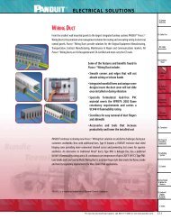
5-37.Fuseholders 11/20/03 11:22 AM Page 35<br />
Fuse Holder Covers<br />
Specifications:<br />
¥ Material, Thermoplastic<br />
¥ Thermal Rating, 125¡ C (RT1, per UL 746)<br />
¥ Flammability, VO (per UL 94)<br />
¥ UL Listed Accessories Under File No. E181825<br />
¥ In Application, Protection is Consistent With IEC Standard 529,<br />
Designation IP2 (finger safe)*<br />
¥ Opening Allows View of Self-Indicating Fuses<br />
¥ Holes for Test Probes and Re-tightening of Wire Terminations<br />
¥ Covers Fit Most Fuse Holder Brands<br />
Catalog#: For Use W/Fuse Holder#: Fuse Type: <strong>Volt</strong>age: Amp:<br />
CHR230 F30A/R30A H/R 250 30<br />
CHR260 F60A/R60A H/R 250 60<br />
CHR2100 RF100A/R100A H/R 250 100<br />
CHR630 6F30A/6R30A H/R <strong>600</strong> 30<br />
CHR660 6F60A/6R60A H/R <strong>600</strong> 60<br />
CHR6100 R6F100A/6R100A H/R <strong>600</strong> 100<br />
CJ630 6J30A J <strong>600</strong> 30<br />
CJ660 6J60A J <strong>600</strong> 60<br />
CC630 6CC30 CC <strong>600</strong> 30<br />
CC660 6CC60 CD <strong>600</strong> 60<br />
CCM630** 6M30A/6CCM30A MISC <strong>600</strong> 30<br />
* Applications involving fuse holders other than Marathon may not provide IP2 finger protection.<br />
** Covers are recognized if used with recognized fuses.<br />
35<br />
Fuseholders
5-37.Fuseholders 11/20/03 11:22 AM Page 36<br />
Fuseholders<br />
36<br />
Fuse Holder Covers<br />
Catalog Name Figure A B C D E F<br />
CHR230 Fig 1 3.76 1.67 0.86 2.54 0.40 0.30<br />
CHR260 Fig 1 5.80 2.16 1.07 3.66 0.47 0.42<br />
CHR2100 Fig 2 7.38 2.41 1.49 4.90 0.38 0.46<br />
CHR630 Fig 1 7.56 1.71 1.10 5.58 0.47 0.42<br />
CHR660 Fig 1 8.30 2.37 1.35 6.32 0.35 0.42<br />
CHR6100 Fig 2 9.34 2.45 1.49 6.90 0.38 0.46<br />
CJ630 Fig 1 4.30 1.95 0.90 2.66 0.35 0.30<br />
CJ660 Fig 1 5.04 2.07 1.35 3.10 0.35 0.42<br />
CC630 Fig 3 3.83 1.69 0.74 2.34 0.34 0.30<br />
CC660 Fig 1 4.58 1.95 0.90 2.66 0.35 0.42<br />
CCM630 Fig 3 3.83 1.69 0.74 2.34 0.34 0.30<br />
MM = Dim X 25.4<br />
Figure 1:<br />
Figure 2:<br />
Figure 3:
5-37.Fuseholders 11/20/03 11:22 AM Page 37<br />
Class CC, G and Midget<br />
Fuse Holder Accessories<br />
DIN Rail Adapter (Catalog# DIN R-2)<br />
This adapter is for use with the Class CC (30A), Midget and Class G fuse holders. The DIN R-2 snaps<br />
securely to the Marathon fuse holders and to DIN rails without tools. This permits the holders to mount<br />
directly to standard and low profile 35mm symmetrical and 32mm asymmetrical DIN rails. They may be<br />
removed from rails by lifting the disconnect tab.<br />
Cover/Puller (Catalog# CVR-MCC)<br />
MarathonÕs Cover/Puller was designed for use with the Class CC (30A), Midget and Class G (15 & 20 amp<br />
only) fuse holders. Once installed, the Cover/Puller provides an easy and safe way to remove fuses. In<br />
application, protection is consistent with IEC Standard 529, designation IP2 (finger safe).<br />
37<br />
Fuseholders
38-50.power blocks 11/20/03 11:24 AM Page 38<br />
Power Blocks<br />
General Information:<br />
Power Terminal Blocks<br />
Power Terminal Blocks are available in seven molding sizes. They are identified by the first three digits of the catalog number.<br />
The 140, 142, 143, 144 and 145 series are manufactured with general purpose phenolic rated at 150¡ C. The 141 and 132<br />
series are manufactured of high impact thermoplastic rated at 125¡ C.<br />
All Power Terminal Blocks are UL recognized file number E62806 and CSA certified file number LR19766, unless noted.<br />
Connector Wire Hole Size:<br />
Conductor Opening Diameter of Opening<br />
#10-18 . . . . . . . . . . . . . . . . . . . . . . . . . .158Ó<br />
#4-14 . . . . . . . . . . . . . . . . . . . . . . . . . . .250Ó<br />
#2-14 . . . . . . . . . . . . . . . . . . . . . . . . . . .312Ó<br />
#2/0-14 . . . . . . . . . . . . . . . . . . . . . . . . . .438Ó<br />
#250MCM-6 . . . . . . . . . . . . . . . . . . . . . .630Ó<br />
#315MCM-6 . . . . . . . . . . . . . . . . . . . . . .718Ó<br />
#400MCM-6 . . . . . . . . . . . . . . . . . . . . . .769Ó<br />
#500MCM-4 . . . . . . . . . . . . . . . . . . . . . .875Ó<br />
Wire hole openings are designed to accept stranded conductors with the number of strands specified in UL 486. Consult factory<br />
for other diameters.<br />
Ratings and Standards:<br />
The voltage ratings of terminal blocks are based upon the minimum spacing between electrically conductive parts line to line<br />
through air and over surface and line to ground through air and over surface.<br />
Class A<br />
Service equipment including deadfront switchboards, panel boards, service entrance devices.<br />
Class B<br />
Commercial appliances including business equipment, electronic data processing equipment and the like.<br />
Class C<br />
General industrial and machine tool controls which can be further defined as equipment falling under UL 508.<br />
Ratings based on UL 1059 may be higher in some cases depending on application.<br />
Spacing Requirements*:<br />
<strong>Volt</strong>age Thru Air Over Surface<br />
51-150 .500 .750<br />
Class A 151-300 .750 1.250<br />
301-<strong>600</strong> 1.000 2.000<br />
51-150 .063 .063<br />
Class B 151-300 .094 .094<br />
301-<strong>600</strong> .375 .500<br />
51-150 .125 .250<br />
Class C 151-300 .250 .375<br />
*In Inches<br />
301-<strong>600</strong> .375 .500<br />
Applications:<br />
Designed for use with heating, air conditioning and refrigeration, elevator systems, material handling equipment, control<br />
panels, motor control, switchgear, and any area where power needs to be distributed to more than one load.<br />
38
38-50.power blocks 11/20/03 11:24 AM Page 39<br />
Power Distribution Blocks<br />
<strong>600</strong> <strong>Volt</strong>s<br />
Specifications:<br />
Catalog #<br />
1411403<br />
1412403<br />
1413403<br />
1414403<br />
1411400<br />
1412400<br />
1413400<br />
1414400<br />
1421570<br />
1422570<br />
1423570<br />
1402402<br />
1403402<br />
1402401<br />
1403401<br />
1402404<br />
1403404<br />
1441401<br />
1442401<br />
1443401<br />
1431552<br />
1432552<br />
1433552<br />
1431553<br />
1432553<br />
1433553<br />
1441560<br />
1442560<br />
1443560<br />
1431555<br />
1432555<br />
1433555<br />
1441551<br />
1442551<br />
1443551<br />
¥ Connector, High Conductive Aluminum, Tin Plated<br />
¥ Amp Rating Based on NEC Table 310-16 Using 75¡ C Copper Wire<br />
¥ *Wire Connector Rated 90¡ C<br />
¥ UL Recognized File No. E62806<br />
¥ CSA Certified File No. LR19766<br />
¥<br />
** Openings rated for #4-14 AWG are multiple wire rated:<br />
(2) #10 CU Str, (2 to 4) #12 CU Str, and (2 to 4) #14 CU Str.<br />
Poles<br />
1<br />
2<br />
3<br />
4<br />
1<br />
2<br />
3<br />
4<br />
1<br />
2<br />
3<br />
2<br />
3<br />
2<br />
3<br />
2<br />
3<br />
1<br />
2<br />
3<br />
1<br />
2<br />
3<br />
1<br />
2<br />
3<br />
1<br />
2<br />
3<br />
1<br />
2<br />
3<br />
1<br />
2<br />
3<br />
Amps<br />
60<br />
115<br />
175<br />
175<br />
175<br />
310<br />
335<br />
335<br />
335<br />
335<br />
350<br />
380<br />
Connector<br />
Configuration<br />
*<br />
*<br />
*<br />
*<br />
Line Openings Connector<br />
Load<br />
Wire Range per pole Configuration Wire Range<br />
#2-#14AWG<br />
#2-#14AWG<br />
2/0-#14AWG<br />
2/0-#14AWG<br />
2/0-#14AWG<br />
350MCM-#6AWG<br />
400MCM-#6AWG<br />
400MCM-#6AWG<br />
400MCM-#6AWG<br />
400MCM-#6AWG<br />
2/0-#14AWG<br />
500MCM-#4AWG<br />
39<br />
1<br />
1<br />
1<br />
1<br />
1<br />
1<br />
1<br />
1<br />
1<br />
1<br />
2<br />
1<br />
#10-#18AWG<br />
#10-#18AWG<br />
** #4-#14AWG<br />
** #4-#14AWG<br />
** #4-#14AWG<br />
** #4-#14AWG<br />
#2-#14AWG<br />
#2-#14AWG<br />
#2-#14AWG<br />
#2-#14AWG<br />
** #4-#14AWG<br />
#2-#14AWG<br />
Openings<br />
per pole<br />
2<br />
4<br />
4<br />
4<br />
6<br />
6<br />
6<br />
4<br />
6<br />
8<br />
6<br />
6<br />
Power Blocks
38-50.power blocks 11/20/03 11:25 AM Page 40<br />
Power Blocks<br />
<strong>600</strong> <strong>Volt</strong>s<br />
Catalog #<br />
1451579<br />
1452579<br />
1453579<br />
1431587<br />
1432587<br />
1433587<br />
1451594<br />
1452594<br />
1453594<br />
1451552<br />
1452552<br />
1453552<br />
1451592<br />
1452592<br />
1453592<br />
1451587<br />
1452587<br />
1453587<br />
1451586<br />
1452586<br />
1453586<br />
1451411<br />
1452411<br />
1453411<br />
1421970<br />
1422970<br />
1423970<br />
1431953<br />
1432953<br />
1433953<br />
1431955<br />
1432955<br />
1433955<br />
1451992<br />
1452992<br />
1453992<br />
1451986<br />
1452986<br />
1453986<br />
1453401<br />
Poles<br />
1<br />
2<br />
3<br />
1<br />
2<br />
3<br />
1<br />
2<br />
3<br />
1<br />
2<br />
3<br />
1<br />
2<br />
3<br />
1<br />
2<br />
3<br />
1<br />
2<br />
3<br />
1<br />
2<br />
3<br />
1<br />
2<br />
3<br />
1<br />
2<br />
3<br />
1<br />
2<br />
3<br />
1<br />
2<br />
3<br />
1<br />
2<br />
3<br />
1<br />
Power Distribution Blocks (Cont.)<br />
Amps<br />
380<br />
380<br />
380<br />
380<br />
760<br />
665<br />
760<br />
840<br />
175<br />
380<br />
350<br />
760<br />
760<br />
2280<br />
Specifications:<br />
Connector<br />
Configuration<br />
CU<br />
CU<br />
¥ Connector, High Conductive Aluminum, Tin Plated<br />
¥ Amp Rating Based on NEC Table 310-16 Using 75¡ C, Copper Wire<br />
¥ CU-Connector, High Conductive Copper, Tin Plated<br />
(Meets Copper Only Automotive Standard)<br />
¥ UL Recognized File No. E62806<br />
¥ CSA Certified File No. LR19766<br />
¥<br />
** Openings rated for #4-14 AWG are multiple wire rated:<br />
(2) #10 CU Str, (2 to 4) #12 CU Str, and (2 to 4) #14 CU Str.<br />
Line Openings Connector<br />
Load<br />
Wire Range per pole Configuration Wire Range<br />
500MCM-#4AWG<br />
500MCM-#4AWG<br />
500MCM-#4AWG<br />
500MCM-#4AWG<br />
500MCM-#4AWG<br />
500MCM-#4AWG<br />
350MCM-#4AWG<br />
500MCM-#4AWG<br />
<strong>600</strong>MCM-#2AWG<br />
2/0-#14AWG<br />
500MCM-#4AWG<br />
2/0-#14AWG<br />
500MCM-#4AWG<br />
500MCM-#4AWG<br />
500MCM-#6AWG<br />
40<br />
1<br />
1<br />
1<br />
1<br />
2<br />
1<br />
2<br />
2<br />
1<br />
1<br />
2<br />
2<br />
2<br />
6<br />
CU<br />
CU<br />
CU<br />
CU<br />
CU<br />
2/0-#14AWG<br />
350MCM-#6AWG<br />
#2-14AWG<br />
#2-#14AWG<br />
#2-#14AWG<br />
** #4-#14AWG<br />
2/0-#14AWG<br />
2/0-#14AWG<br />
3/0-#6AWG<br />
** #4-#14AWG<br />
** #4-#14AWG<br />
#2-#14AWG<br />
** #4-#14AWG<br />
#2-#14AWG<br />
2/0-#14AWG<br />
2/0-#14AWG<br />
Openings<br />
per pole<br />
6<br />
1<br />
3<br />
1<br />
3<br />
1<br />
3<br />
8<br />
12<br />
12<br />
4<br />
8<br />
4<br />
4<br />
6<br />
6<br />
12<br />
8<br />
18
38-50.power blocks 11/20/03 11:25 AM Page 41<br />
Power Blocks (Splicer)<br />
<strong>600</strong> <strong>Volt</strong>s<br />
Specifications:<br />
¥ Connector, High Conductive Aluminum, Tin Plated<br />
¥ CU-Connector, High Conductive Copper, Tin Plated<br />
(Meets Copper Only Automotive Standard)<br />
¥ Amp Rating Based on NEC Table 310-16 Using 75¡ C Copper Wire<br />
¥ *Wire Connector Rated 90¡ C<br />
¥ UL Recognized File No. E62806<br />
¥ CSA Certified File No. LR19766<br />
¥<br />
Connector<br />
Line Openings Connector<br />
Load Openings<br />
Catalog# Poles Amps Configuration Wire Range Per Pole Configuration Wire Range Per Pole<br />
1411300 1<br />
1412300<br />
1413300<br />
2<br />
3<br />
115 *<br />
#2-#14AWG 1 #2-#14AWG 1<br />
1414300 4<br />
1421552 1<br />
1422552 2 115 *<br />
#2-#14AWG 1 #2-#14AWG 1<br />
1423552 3<br />
1421572 1<br />
1422572 2 175 *<br />
2/0-#14AWG 1 2/0-#14AWG 1<br />
1423572 3<br />
1402801<br />
1403801<br />
2<br />
3<br />
255 250MCM-#6AWG 1 250MCM-#6AWG 1<br />
1431123 1<br />
1432123 2 255 250MCM-#6AWG 1 250MCM-#6AWG 1<br />
1433123 3<br />
1402303<br />
1403303<br />
2<br />
3<br />
310 350MCM-#6AWG 1 350MCM-#6AWG 1<br />
1431126 1<br />
1432126 2 310 350MCM-#6AWG 1 350MCM-#6AWG 1<br />
1433126 3<br />
1441557 1<br />
1442557 2 420 <strong>600</strong>MCM-#4AWG 1 <strong>600</strong>MCM-#4AWG 1<br />
1443557 3<br />
1451129 1<br />
1452129 2 620 350MCM-#4AWG 2 350MCM-#4AWG 2<br />
1453129 3<br />
1451301 1<br />
1452301 2 760 500MCM-#4AWG 2 500MCM-#4AWG 2<br />
1453301 3<br />
1421121<br />
1422121<br />
1423121<br />
1<br />
2<br />
3<br />
175<br />
*<br />
CU<br />
2/0-#14AWG 1<br />
CU<br />
2/0-#14AWG 1<br />
1431124 1<br />
1432124 2 255 250MCM-#6AWG 1 250MCM-#6AWG 1<br />
1433124 3<br />
41<br />
Power Blocks
38-50.power blocks 11/20/03 11:25 AM Page 42<br />
Power Blocks<br />
<strong>600</strong> <strong>Volt</strong>s<br />
Specifications:<br />
¥ Connector, High Conductive Copper, Tin Plated<br />
¥ Stud, Brass, Tin Plated<br />
¥ Amp Rating Based on NEC Table 310-16 Using 75¡ C Copper Wire<br />
¥ UL Recognized File No. E62806<br />
¥ CSA Certified File No. LR19766<br />
¥<br />
42<br />
Power Stud Blocks<br />
Connector<br />
Line Openings Connector<br />
Load Openings<br />
Catalog# Poles Amps Configuration Wire Range Per Pole Configuration Wire Range Per Pole<br />
1421123 1<br />
1422123<br />
1423123<br />
2<br />
3<br />
200 1/4-20 Screw 1 1/4-20 Screw<br />
1<br />
1421122 1<br />
1422122 2 200 1/4-20 X 9/16 Stud 1 1/4-20 X 9/16 Stud 1<br />
1423122 3<br />
1431563 1<br />
1432563 2 230 3/8-16 X1 3/16 Stud 1 3/8-16 X1 3/16 Stud 1<br />
1433563 3<br />
1431561 1<br />
1432561 2 230 3/8-16 X1 3/16 Stud 1 1/4-20 X1 3/16 Stud 1<br />
1433561 3<br />
1441122 1<br />
1442122 2 260 3/8-16 X1 7/16 Stud 1 1/4-20 X 9/16 Stud 2<br />
1443122 3<br />
1441553 1<br />
1442553 2 230 3/8-16 X1 7/16 Stud 1 3/8-16 X1 7/16 Stud 1<br />
1443553 3<br />
1451606 1<br />
1452606 2 410 1/2-13 X1 7/16 Stud 1 1/2-13 X1 7/16 Stud 1<br />
1453606 3<br />
1451573<br />
1452573<br />
1<br />
2 360 3/8-16 X1 7/16 Stud 1 3/8-16 X1 7/16 Stud<br />
2<br />
1453573 3<br />
1451583 1<br />
1452583 2 360 3/8-16 X1 7/16 Stud 1 1/4-20 X1 7/16 Stud 2<br />
1453583 3<br />
1441614 1<br />
1442614 2 840 3/8-16 X 1 Stud 1 3/8-16 X 1 Stud 1<br />
1443614 3
38-50.power blocks 11/20/03 11:25 AM Page 43<br />
Power/Splicer Stud Blocks<br />
<strong>600</strong> <strong>Volt</strong>s<br />
Specifications:<br />
¥ Connector, High Conductive Aluminum, Tin Plated<br />
¥ Stud, Brass, Tin Plated<br />
¥ Quick Connect, Brass, Tin Plated<br />
¥ 10-32 Screw, Brass, Nickel Plated<br />
¥ Amp Rating Based on NEC Table 310-16 Using 75¡ C Copper Wire<br />
¥ *Wire Connector Rated 90¡ C<br />
¥ UL Recognized File No. E62806<br />
¥ CSA Certified File No. LR19766<br />
¥<br />
Connector<br />
Line Openings Connector<br />
Load Openings<br />
Catalog# Poles Amps Configuration Wire Range Per Pole Configuration Wire Range Per Pole<br />
1411200 1<br />
1412200<br />
1413200<br />
2<br />
3<br />
115<br />
#2-#14AWG 1 10-32 Screw 1<br />
1414200 4<br />
1411201 1<br />
1412201<br />
1413201<br />
2<br />
3<br />
115<br />
#2-#14AWG 1 10-32 Tapped Hole 1<br />
1414201 4<br />
1411202 1<br />
1412202<br />
1413202<br />
2<br />
3<br />
115<br />
#2-#14AWG 1 .25X.032 Qk Cnct 4<br />
1414202 4<br />
1411203 1<br />
1412203<br />
1413203<br />
2<br />
3<br />
115<br />
#2-#14AWG 1 10-32 X .60 Stud 1<br />
1414203 4<br />
1411205 1<br />
1412205<br />
1413205<br />
2<br />
3<br />
115<br />
#2-#14AWG 1 #10-32 Hole & (2) QC 1<br />
1414205 4<br />
1411301 1<br />
1412301<br />
1413301<br />
2<br />
3<br />
115<br />
#2-#14AWG 1 #2-#14AWG & (1) QC 1<br />
1414301 4<br />
1431559 1<br />
1432559 2 310 350MCM-#6AWG 1 3/8-16 X 11/8 Stud 1<br />
1433559 3<br />
1421411<br />
1422411<br />
1<br />
2 175 *<br />
2/0-#14AWG 1 M6 Hole 1<br />
1423411 3<br />
1421553<br />
1422553<br />
1<br />
2 175 *<br />
2/0-#14AWG 1 1/4-20 Tapped Hole 1<br />
1423553 3<br />
43<br />
Power Blocks
38-50.power blocks 11/20/03 11:25 AM Page 44<br />
Power Blocks<br />
<strong>600</strong> <strong>Volt</strong>s<br />
Specifications:<br />
Power Splicer/Stud Blocks (Cont.)<br />
¥ Connector, High Conductive Aluminum, Tin Plated<br />
¥ Stud, Brass, Tin Plated<br />
¥ Quick Connect, Brass, Tin Plated<br />
¥ 10-32 Screw, Brass, Nickel Plated<br />
¥ Amp Rating Based on NEC Table 310-16 Using 75¡ C, Copper Wire<br />
¥ *Wire Connector Rated 90¡ C<br />
¥ UL Recognized File No. E62806<br />
¥ CSA Certified File No. LR19766<br />
¥<br />
Connector<br />
Line Openings Connector<br />
Load Openings<br />
Catalog# Poles Amps Configuration Wire Range Per Pole Configuration Wire Range Per Pole<br />
1421574<br />
1422574<br />
1<br />
2 175 *<br />
2/0-#14AWG 1 1/4-20 X 1/2 Stud 1<br />
1423574 3<br />
1431590<br />
1432590<br />
1<br />
2 175 *<br />
2/0-#14AWG 1 1/4-20 X 1/2 Stud 1<br />
1433590 3<br />
1441569 1<br />
1442569 2 380 500MCM-#4AWG 1 1/4-20 X 17/32 Stud 2<br />
1443569 3<br />
1441575 1<br />
1442575 2 380 500MCM-#4AWG 1 3/8-16 X 21/32 Stud 1<br />
1443575 3<br />
1451596 1<br />
1452596 2 545 1000MCM-500MCM 1 3/8-16 X 1 19/32 Stud 2<br />
1453596 3<br />
1451599 1<br />
1452599 2 760 500MCM-#4AWG 2 3/8-16 X 1 5/8 Stud 2<br />
1453599 3<br />
1451610 1<br />
1452610 2 760 500MCM-#4AWG 2 1/2-13 X 11/16 Stud 1<br />
1453610 3<br />
44
38-50.power blocks 11/20/03 11:26 AM Page 45<br />
New Thermoplastic Power Block<br />
General Specifications:<br />
¥ Amp Rating Based on NEC Table 310-16 Using 75¡ C Copper Wire<br />
¥ Wire Connector Rated 90¡ C ¥ CSA Certified File No. LR19766<br />
¥ UL Recognized File No. E62806 ¥<br />
Power Distribution Block and Power Block-Splicer Specifications:<br />
¥ Connector, High Conductive Aluminum, Tin Plated<br />
¥ CU-Connector, High Conductive Copper, Tin Plated<br />
Power Distribution Blocks<br />
Connector<br />
Line Openings Connector<br />
Load Openings<br />
Catalog# Poles Amps Configuration Wire Range Per Pole Configuration Wire Range Per Pole<br />
1321570 1<br />
1322570<br />
1323570<br />
2<br />
3<br />
4<br />
1320570 Adder<br />
1321580 1<br />
1322580<br />
1323580<br />
2<br />
3<br />
175 #2/0-#14AWG 1 #4-#14AWG 6<br />
1320580 Adder Multiple Wire Rated:<br />
1321970 1 CU CU<br />
2 #10 CU Str<br />
1322970<br />
1323970<br />
2<br />
3<br />
2 to 4 #12 CU Str<br />
2 to 4 #14 CU Str<br />
4<br />
1320970 Adder<br />
Power Blocks/Splicer<br />
Connector<br />
Line Openings Connector<br />
Load Openings<br />
Catalog# Poles Amps Configuration Wire Range Per Pole Configuration Wire Range Per Pole<br />
1321572 1<br />
1322572 2<br />
1323572 3<br />
1320572<br />
1321972<br />
Adder<br />
1<br />
175<br />
CU<br />
#2/0-#14AWG 1<br />
CU<br />
#2/0-#14AWG 1<br />
1322972 2<br />
1323972 3<br />
1320972 Adder<br />
Power Stud Block and Power Splicer/Stud Block Specifications:<br />
¥ Connector, High Conductive Aluminum, Tin Plated (*Connector, High Conductive Copper, Tin Plated)<br />
¥ Stud, Brass, Tin Plated ¥ Metric Studs-Steel, Zinc Plated<br />
Power Stud Blocks*<br />
Connector<br />
Line Openings Connector<br />
Load Openings<br />
Catalog# Poles Amps Configuration Wire Range Per Pole Configuration Wire Range Per Pole<br />
1321122 1<br />
1322122<br />
1323122<br />
2<br />
3<br />
1/4-20 X 9/16 Stud 1/4-20 X 9/16 Stud<br />
1320122<br />
1321422<br />
Adder<br />
1<br />
200 1 1<br />
1322422<br />
1323422<br />
2<br />
3<br />
M6 X 15 Stud M6 X 15 Stud<br />
1320422 Adder<br />
Power Splicer/Stud Blocks<br />
Connector<br />
Line Openings Connector<br />
Load Openings<br />
Catalog# Poles Amps Configuration Wire Range Per Pole Configuration Wire Range Per Pole<br />
1321574 1<br />
1322574<br />
1323574<br />
2<br />
3<br />
1/4-20 X 1/2 Stud<br />
1320574<br />
1321474<br />
Adder<br />
1<br />
175 #2/0-#14AWG 1 1<br />
1322474<br />
1323474<br />
2<br />
3<br />
M6 Stud X 13 Stud<br />
1320474 Adder<br />
45<br />
<strong>600</strong> <strong>Volt</strong>s<br />
Power Blocks
38-50.power blocks 11/20/03 11:26 AM Page 46<br />
Power Blocks<br />
Specifications:<br />
¥ Material .06 Clear Protective Plastic<br />
¥ Two Thread Cutting Screws Furnished Per Cover<br />
¥ Covers Are Slotted For Easy Installation<br />
¥ Covers Are Available For The 140, 141, 142, 143, 144, 145<br />
132 Series Power Blocks:<br />
¥ Hinged, Thermoplastic, 125¡ C<br />
Dimensions (IN):<br />
Catalog # A B Figure #<br />
CC1402<br />
CC1403<br />
2.75<br />
4.00<br />
2.25<br />
2.25<br />
1<br />
CC1411 .77 2.40<br />
CC1412<br />
CC1413<br />
1.42<br />
2.05<br />
2.40<br />
2.40<br />
2<br />
CC1414 2.68 2.40<br />
CC1421 1.06 2.75<br />
CC1422 1.87 2.75 1<br />
CC1423 2.68 2.75<br />
CC1431 1.78 3.38<br />
CC1432 3.31 3.38 1<br />
CC1433 4.84 3.38<br />
CC1441 2.12 4.00<br />
CC1442 4.00 4.00 1<br />
CC1443 5.87 4.00<br />
CC1451 2.87 4.50<br />
CC1452 5.56 4.50 1<br />
CC1453<br />
CH1321<br />
8.28 4.50<br />
CH1322<br />
CH1323<br />
- - 3<br />
46<br />
Power Block Covers<br />
A<br />
Figure 1<br />
B<br />
Figure 2<br />
Figure 3
38-50.power blocks 11/20/03 11:26 AM Page 47<br />
Grounding Lugs<br />
Specifications:<br />
¥ Connector, High Conductive Aluminum, Tin Plated<br />
¥ Per Code Ð Screw Is Green<br />
¥ UL Recognized File No. E43665<br />
¥ CSA Certified File No. 63510-25<br />
Catalog # (Connector Wire Range)<br />
GL02 (#2-#14 AWG)<br />
GL35 (350MCM-#6 AWG)<br />
47<br />
GL20 (#2/0-#14 AWG)<br />
Power Blocks
38-50.power blocks 11/20/03 11:26 AM Page 48<br />
Power Blocks<br />
132 Series<br />
140 Series<br />
141 Series<br />
Power Terminal Blocks Dimensions<br />
.83<br />
[21.0]<br />
REF.<br />
Adder 1 POLE 2 POLE 3 POLE<br />
2 POLE 3 POLE<br />
1.46<br />
[37.2]<br />
REF.<br />
1.27<br />
[32.3]<br />
2.10<br />
[53.3]<br />
REF.<br />
48<br />
2.07<br />
[52.5]<br />
.38<br />
[9.7]<br />
2.67<br />
[67.7]<br />
2.47<br />
[62.7]<br />
1.91<br />
[48.4]<br />
.44<br />
TYP. AT BOSS<br />
.52<br />
[11.2] [13.2]<br />
.47<br />
[11.9]<br />
2.74<br />
[69.5]<br />
REF.<br />
¯.201<br />
[5.11]<br />
2.29<br />
[58.1]<br />
1.93<br />
[49.1]<br />
.18<br />
[4.5]<br />
ALL POCKETS<br />
THRU<br />
1.52<br />
.32 [38.7]<br />
[8.1]<br />
.70<br />
[17.7]<br />
.19<br />
[4.9]<br />
1 POLE 2 POLE 3 POLE 4 POLE<br />
.55<br />
[14.1]
38-50.power blocks 11/20/03 11:26 AM Page 49<br />
Power Terminal Blocks Dimensions<br />
142 Series<br />
143 Series<br />
1 POLE 2 POLE 3 POLE<br />
1 POLE 2 POLE 3 POLE<br />
49<br />
Power Blocks
38-50.power blocks 11/20/03 11:26 AM Page 50<br />
Power Blocks<br />
Power Terminal Blocks Dimensions<br />
144 Series<br />
145 Series<br />
1 POLE 2 POLE 3 POLE<br />
1 POLE 2 POLE 3 POLE<br />
50
Heavy Duty Terminal Blocks<br />
General Information:<br />
Heavy Duty Terminal Blocks are available in two styles Ð Deadfront Type (1100, 1200, 985 and 0987 series) and Barrier<br />
Type (1500 and 1<strong>600</strong> series).<br />
Ratings and Standards:<br />
The voltage ratings of terminal blocks are based upon the minimum spacing between electrically conductive parts line to line<br />
through air and over surface and line to ground through air and over surface.<br />
Class A<br />
Service equipment including deadfront switchboards, panel boards, service entrance devices.<br />
Class B<br />
Commercial appliances including business equipment, electronic data processing equipment and the like.<br />
Class C<br />
General industrial and machine tool controls which can be further defined as equipment falling under UL 508.<br />
Ratings based on UL 1059 may be higher in some cases depending on application.<br />
Spacing Requirements*:<br />
<strong>Volt</strong>age Thru Air Over Surface<br />
51-150 .500 .750<br />
Class A 151-300 .750 1.250<br />
301-<strong>600</strong> 1.000 2.000<br />
51-150 .063 .063<br />
Class B 151-300 .094 .094<br />
301-<strong>600</strong> .375 .500<br />
51-150 .125 .250<br />
Class C 151-300 .250 .375<br />
*In Inches<br />
301-<strong>600</strong> .375 .500<br />
Applications:<br />
Designed for electrical termination of wire with or without the use of a wire terminal. These rugged terminal blocks are widely<br />
used in such industries as traffic control, utilities, switchgear and other utility related equipment.<br />
51<br />
Heavy Duty Terminal Blocks
Heavy Duty Terminal Blocks<br />
1100 Series - Deadfront Type<br />
<strong>600</strong> <strong>Volt</strong>s<br />
Specifications:<br />
Heavy Duty Terminal Blocks<br />
¥ Base, General Purpose Phenolic, 150¡ C<br />
¥ Connector, Aluminum Tin Plated<br />
¥ Spring, Copper, Use 11XXS<br />
¥ Screws, Brass, Tin Plated<br />
¥ Wire Range #6-#18 Awg CU Ð 65 Amps<br />
¥ Wire Range With Spring #6-#14 Awg CU Ð 65 Amps<br />
¥ UL Recognized File No. #E62806<br />
¥ CSA Certified File No. LR19766<br />
¥ - Wire Range Reduced #8-#18 Awg CU<br />
Catalog# Catalog# # of Poles A B<br />
1102 1102S 2 1.69 1.31<br />
1104 1104S 4 2.50 2.12<br />
1106 1106S 6 3.38 3.00<br />
1107 110S 7 3.88 3.50<br />
1108 1108S 8 4.25 3.88<br />
1112 1112S 12 6.00 5.62<br />
S=Copper Pressure Spring MM = Dim X 25.4<br />
52
Heavy Duty Terminal Blocks<br />
1103P and 1200 Series - Deadfront Type<br />
<strong>600</strong> <strong>Volt</strong>s<br />
Specifications:<br />
¥ Base, General Purpose Phenolic, 150¡ C<br />
¥ Connector, Aluminum, Tin Plated<br />
¥ Screws, Steel, Tin Plated<br />
¥ 1103 P Wire Range #4-#14 Awg CU Ð 70 Amps<br />
¥ 1200 Wire Range #4-#18 Awg CU Ð 70 Amps<br />
¥ UL Recognized File No. #E62806<br />
¥ CSA Certified File No. LR19766<br />
¥ - Wire Range Reduced 1103 P #6-#18 Awg CU<br />
1200 #6-#14 Awg CU<br />
Catalog# # of Poles A B<br />
1202 2 1.81 1.44<br />
1204 4 2.81 2.44<br />
1206 6 3.81 3.44<br />
53<br />
MM = Dim X 25.4<br />
1103 P Series 1200 Series<br />
Heavy Duty Terminal Blocks
Heavy Duty Terminal Blocks<br />
0987 RZ Series - Deadfront Type<br />
<strong>600</strong> <strong>Volt</strong>s<br />
Specifications:<br />
Heavy Duty Terminal Blocks<br />
¥ Base, Thermoplastic, 105¡ C<br />
¥ Connector, Copper Alloy, Nickel Plated (TC Tubular Clamp)<br />
¥ Printed Circuit Contact, Copper Alloy Electro Tin Plated (PC)<br />
¥ Wire Range #8-#24 Awg Ð 50 Amps<br />
¥ Contact Factory For Multiple Wire Combinations<br />
¥ .475 Centerline Spacing<br />
¥ UL Recognized File No. #E47811<br />
¥ CSA Certified File No. LR19766<br />
¥ - Wire Range Reduced #10-#24 Awg<br />
54<br />
Dimensions<br />
Catalog # # of poles A B<br />
0987 RZ TC 02 2 0.95 N/A<br />
0987 RZ TC 03 3 1.43 0.48<br />
0987 RZ TC 04 4 1.90 0.95<br />
0987 RZ TC 05 5 2.38 1.43<br />
0987 RZ TC 06 6 2.85 1.90<br />
0987 RZ TC 07 7 3.33 2.38<br />
0987 RZ TC 08 8 3.80 2.85<br />
0987 RZ TC 09 9 4.28 3.33<br />
0987 RZ TC 10 10 4.75 3.80<br />
0987 RZ TC 11 11 5.23 4.28<br />
0987 RZ TC 12 12 5.70 4.75<br />
¥ For PC version substitute PC for TC in catalog number<br />
¥ DIN Adaptor is available for 0987 Series
Heavy Duty Terminal Blocks<br />
985 GP Series - Deadfront Type<br />
<strong>600</strong> <strong>Volt</strong>s<br />
Specifications:<br />
¥ Base, General Purpose Phenolic, 150¡ C<br />
¥ Connector, Aluminum, Tin Plated<br />
¥ Screws, Steel, Nickel Plated<br />
¥ Wire Range #4-#18 Awg Copper Wire Ð 85 Amps<br />
¥ Multiple Wire Combinations For Solid Or Stranded Copper Wire Are:<br />
1 #18 Awg to 1 #4 Awg 2 to 6 #14 Awg<br />
2 #8 Awg 2 to 6 #16 Awg<br />
2 to 4 #10 Awg 2 to 8 #18 Awg<br />
2 to 4 #12 Awg<br />
¥ .625 Center-Line Spacing<br />
¥ UL Recognized File No. E47811<br />
¥ CSA Certified File No. LR19766<br />
¥ - Wire Range Reduced #6-#18 Awg<br />
55<br />
Dimensions<br />
Catalog # # of poles A B<br />
985 GP 02 2 1.16 N/A<br />
985 GP 03 3 1.78 0.63<br />
985 GP 04 4 2.41 1.25<br />
985 GP 05 5 3.03 1.88<br />
985 GP 06 6 3.66 2.50<br />
985 GP 07 7 4.28 3.13<br />
985 GP 08 8 4.91 3.75<br />
985 GP 09 9 5.53 4.38<br />
985 GP 10 10 6.16 5.00<br />
985 GP 11 11 6.78 5.63<br />
985 GP 12 12 7.41 6.25<br />
MM = Dim X 25.4<br />
Heavy Duty Terminal Blocks
Heavy Duty Terminal Blocks<br />
1500 Series<br />
<strong>600</strong> <strong>Volt</strong>s<br />
Specifications:<br />
Heavy Duty Terminal Blocks<br />
¥ Base, General Purpose Phenolic, 150¡ C<br />
¥ Connector, Brass, Nickel Plated<br />
¥ Screws, Brass, Nickel Plated, 10-32<br />
¥ Wire Range #10-#16 Awg Copper Wire Ð 30 Amps<br />
¥ With Proper Termination Approved For 75 Amps<br />
¥ 5/8Ó Line To Line Spacing<br />
¥ UL Recognized File No. #E62806<br />
¥ CSA Certified File No. LR19766<br />
¥<br />
1500 STD 1500 DJ 1500 DJSV 1500 ST* 1500 SC 1500 H<br />
Standard Removable Removable 10-32 Stud Short Circuiting Standard Connector<br />
Connector Connector With Connector With Removable Bar With Brass With Hinge Cover<br />
Brass Insert Brass Insert Connector Insert 4 Shorting<br />
Removable Cover Pins Per Block<br />
* STRC: 10-32 Stud with Riveted Connector<br />
MCJ-Jumper Available<br />
Catalog #: # of Poles Catalog #: # of Poles<br />
1504 STD 4 1504 ST 4<br />
1506 STD 6 1506 ST 6<br />
1508 STD 8 1508 ST 8<br />
1512 STD 12 1512 ST 12<br />
1504 DJ 4 1504 SC 4<br />
1506 DJ 6 1506 SC 6<br />
1508 DJ 8 1508 SC 8<br />
1512 DJ 12 1512 SC 12<br />
1504 DJSV 4 1504 H 4<br />
1506 DJSV 6 1506 H 6<br />
1508 DJSV 8 1508 H 8<br />
1512 DJSV 12 1512 H 12<br />
56<br />
Catalog #: # of Poles A B<br />
1504 4 3.25 2.88<br />
1506 6 4.50 4.12<br />
1508 8 5.75 5.38<br />
1512 12 8.25 7.88<br />
MM = Dim X 25.4
Heavy Duty Terminal Blocks<br />
1<strong>600</strong> Series<br />
<strong>600</strong> <strong>Volt</strong>s<br />
Specifications:<br />
¥ Base, General Purpose Phenolic, 150¡ C<br />
¥ Connector, Brass, Nickel Plated<br />
¥ Screws, Brass, Nickel Plated, 10-32<br />
¥ Wire Range #10-#16 Awg Copper Wire Ð 30 Amps<br />
¥ With Proper Termination Approved For 75 Amps<br />
¥ 21/32Ó Line To Line Spacing<br />
¥ UL Recognized File No. #E62806<br />
¥ CSA Certified File No. LR19766<br />
¥<br />
1<strong>600</strong> STD 1<strong>600</strong> DJ 1<strong>600</strong> DJSV 1<strong>600</strong> ST* 1<strong>600</strong> SC 1<strong>600</strong> H<br />
Standard Removable Removable 10-32 Stud Short Circuiting Standard Connector<br />
Connector Connector With Connector With Removable Bar With Brass With Hinge Cover<br />
Brass Insert Brass Insert Connector Insert 4 Shorting<br />
Removable Cover Pins Per Block<br />
* STRC: 10-32 Stud with Riveted Connector<br />
MCJ-Jumper Available<br />
Catalog #: # of Poles Catalog #: # of Poles<br />
1604 STD 4 1604 ST 4<br />
1606 STD 6 1606 ST 6<br />
1608 STD 8 1608 ST 8<br />
1612 STD 12 1612 ST 12<br />
1604 DJ 4 1604 SC 4<br />
1606 DJ 6 1606 SC 6<br />
1608 DJ 8 1608 SC 8<br />
1612 DJ 12 1612 SC 12<br />
1604 DJSV 4 1604 H 4<br />
1606 DJSV 6 1606 H 6<br />
1608 DJSV 8 1608 H 8<br />
1612 DJSV 12 1612 H 12<br />
57<br />
Catalog #: # of Poles A B<br />
1604 4 3.75 3.09<br />
1606 6 5.06 4.41<br />
1608 8 6.38 5.72<br />
1612 12 9.00 8.34<br />
MM = Dim X 25.4<br />
Heavy Duty Terminal Blocks
Single/Double Row Terminal Blocks<br />
General Information:<br />
Single Row Terminal Blocks<br />
Single Row Terminal Blocks are available in four basic line to line molding sizes. Some are available in either open or feed<br />
thru/printed circuit designs. The basic material is phenolic. Modifications are also provided on most terminal blocks, including<br />
marking strips.<br />
Ratings and Standards:<br />
The voltage ratings of terminal blocks are based upon the minimum spacing between electrically conductive parts line to line<br />
through air and over surface and line to ground through air and over surface.<br />
Class A<br />
Service equipment including deadfront switchboards, panel boards, service entrance devices.<br />
Class B<br />
Commercial appliances including business equipment, electronic data processing equipment and the like.<br />
Class C<br />
General industrial and machine tool controls which can be further defined as equipment falling under UL 1059.<br />
Reference Chart:<br />
Ratings based on UL 1059 may be higher in some cases depending on application.<br />
Spacing Requirements*:<br />
<strong>Volt</strong>age Thru Air Over Surface<br />
51-150 .500 .750<br />
Class A 151-300 .750 1.250<br />
301-<strong>600</strong> 1.000 2.000<br />
51-150 .063 .063<br />
Class B 151-300 .094 .094<br />
301-<strong>600</strong> .375 .500<br />
51-150 .125 .250<br />
Class C 151-300 .250 .375<br />
301-<strong>600</strong> .375 .500<br />
*In Inches<br />
Catalog Base Max Wire Screw Inches # of<br />
Series Page Amps <strong>Volt</strong>s Material Size for Screw Size L to L Lines Features<br />
411 59 5 *300 Phenolic #18 2-56 .250 1-23 Open Back<br />
599 60 15 150 Phenolic #16 5-40 .375 1-30 Open Back<br />
699 61 20 150 Phenolic #14 6-32 .437 1-23 Open Back<br />
812 62 30 <strong>600</strong> Phenolic #12 8-32 .562 1-18 Open Back<br />
1690 63-64 20 300 Phenolic #14 6-32 .437 1-24 Feed Thru<br />
2590 65 15 150 Phenolic #16 6-32 .375 1-25 Printed Circuit<br />
2690 66-67 20 300 Phenolic #14 6-32/8-32 .437 1-25 Printed Circuit<br />
All voltage ratings based on Class C requirements unless noted.<br />
Open back terminal blocks require an insulator strip to achieve voltage rating.<br />
*Based on Class B requirements.<br />
58
Single Row Terminal Blocks<br />
Kulka ® 411 Series<br />
300 <strong>Volt</strong>s*<br />
Specifications:<br />
MM=Dim X 25.4<br />
*Based on Class B Requirements<br />
¥ Base, Phenolic, 150¡ C<br />
¥ Open Back Design (Insulator Strip Required for <strong>Volt</strong>age Rating)<br />
¥ JJ (GDI-30F) Material Available<br />
¥ Screws, #2-56 Binder Head, Phil-Slot<br />
¥ Terminals, Plated Brass<br />
¥ 1-23 Poles<br />
¥ 1/4Ó Centers<br />
¥ Wire Range With Wire Binding Screw #18-#20 Awg Ð 5 Amps<br />
¥ The Suitability Of These Devices For Greater Currents Shall Be Determined In The End-Use Application<br />
¥ UL Recognized File No. E47811<br />
¥ CSA Certified File No. LR19766<br />
¥<br />
Catalog Number Dimensions<br />
Description of Poles A B<br />
411 GP 01 1 0.75 0.50<br />
411 GP 02 2 1.00 0.75<br />
411 GP 03 3 1.25 1.00<br />
411 GP 04 4 1.50 1.25<br />
411 GP 05 5 1.75 1.50<br />
411 GP 06 6 2.00 1.75<br />
411 GP 07 7 2.25 2.00<br />
411 GP 08 8 2.50 2.25<br />
411 GP 09 9 2.75 2.50<br />
411 GP 10 10 3.00 2.75<br />
411 GP 11 11 3.25 3.00<br />
411 GP 12 12 3.50 3.25<br />
411 GP 13 13 3.75 3.50<br />
411 GP 14 14 4.00 3.75<br />
411 GP 15 15 4.25 4.00<br />
411 GP 16 16 4.50 4.25<br />
411 GP 17 17 4.75 4.50<br />
411 GP 18 18 5.00 4.75<br />
411 GP 19 19 5.25 5.00<br />
411 GP 20 20 5.50 5.25<br />
411 GP 21 21 5.75 5.50<br />
411 GP 22 22 6.00 5.75<br />
411 GP 23 23 6.25 6.00<br />
Hardware Options: (Hardware options may affect<br />
ratings - consult factory)<br />
KT10 = Full Quick Connect (0¡ Flat) See Page 87<br />
KT11 = Full Quick Connect (45¡ Bend) See Page 87<br />
KT12 = Full Quick Connect (90¡ Bend) See Page 87<br />
ST = Full Solder See Page 89<br />
J 410 = Line to Line Jumper See Page 91<br />
3/4 ST = Half Solder See Page 89<br />
KT 16 = Half Quick Connect (0¡ Flat) See Page 87<br />
KT 17 = Half Quick Connect (45¡ Bend) See Page 87<br />
KT 18 = Half Quick Connect (90¡ Bend) See Page 87<br />
Z = Lug Over the Side (.312)<br />
1921 = Printed Circuit Pin (.125)<br />
(Over the Side)<br />
1904 = Feed Thru Solder See Page 93<br />
59<br />
Single/Double Row Terminal Blocks
Single/Double Row Terminal Blocks<br />
Kulka ® 599 Series<br />
150 <strong>Volt</strong>s<br />
Number Dimensions<br />
Catalog of<br />
Description Poles A B<br />
599 GP 01 1 1.03 0.75<br />
599 GP 02 2 1.41 1.12<br />
599 GP 03 3 1.78 1.50<br />
599 GP 04 4 2.16 1.88<br />
599 GP 05 5 2.53 2.25<br />
599 GP 06 6 2.91 2.63<br />
599 GP 07 7 3.28 3.00<br />
599 GP 08 8 3.66 3.38<br />
599 GP 09 9 4.03 3.75<br />
599 GP 10 10 4.41 4.13<br />
599 GP 11 11 4.78 4.50<br />
599 GP 12 12 5.16 4.88<br />
599 GP 13 13 5.53 5.25<br />
599 GP 14 14 5.91 5.63<br />
599 GP 15 15 6.28 6.00<br />
599 GP 16 16 6.66 6.38<br />
599 GP 17 17 7.03 6.75<br />
599 GP 18 18 7.41 7.13<br />
599 GP 19 19 7.78 7.50<br />
599 GP 20 20 8.16 7.88<br />
599 GP 21 21 8.53 8.25<br />
599 GP 22 22 8.91 8.63<br />
599 GP 23 23 9.28 9.00<br />
599 GP 24 24 9.66 9.38<br />
599 GP 25 25 10.03 9.75<br />
599 GP 26 26 10.41 10.13<br />
599 GP 27 27 10.78 10.50<br />
599 GP 28 28 11.16 10.88<br />
599 GP 29 29 11.53 11.25<br />
599 GP 30 30 11.91 11.63<br />
MM=Dim X 25.4<br />
Specifications:<br />
Single Row Terminal Blocks<br />
¥ Base, Phenolic, 150¡ C<br />
¥ Open Back Design (Insulator Strip Required for <strong>Volt</strong>age Rating)<br />
¥ JJ (GDI-30F) Material Available<br />
¥ Screws, #5-40 Binder Head, Phil-Slot<br />
¥ Terminals, Plated Brass<br />
¥ 1-30 Poles<br />
¥ 3/8Ó Centers<br />
¥ Wire Range With Wire Binding Screw #16-#22 Awg Ð 15 Amps<br />
¥ The Suitability Of These Devices For Greater Currents Shall Be Determined In The End-Use Application<br />
¥ UL Recognized File No. E47811<br />
¥ CSA Certified File No. LR19766<br />
¥<br />
Hardware Options: (Hardware options may affect<br />
ratings - consult factory)<br />
KT 28 = Full Quick Connect (0¡ Flat) See Page 87<br />
KT 29 = Full Quick Connect (45¡ Bend) See Page 87<br />
KT 30 = Full Quick Connect (90¡ Bend) See Page 87<br />
J <strong>600</strong> = Line to Line Jumper See Page 91<br />
<strong>600</strong> RJ(S) = Multiple Position Jumper See Page 91<br />
3/4 ST = Half Solder See Page 89<br />
KT 34 = Half Quick Connect (0¡ Flat) See Page 87<br />
KT 35 = Half Quick Connect (45¡ Bend) See Page 87<br />
KT 36 = Half Quick Connect (90¡ Bend) See Page 87<br />
Z = Lug Over the Side (.312) See Page 90<br />
2002 = Stud See Page 93<br />
2004 = Feed Thru Solder See Page 93<br />
2020 = Solder Pin See Page 93<br />
2021 = Solder Pin See Page 93<br />
60
Single Row Terminal Blocks<br />
Kulka ® 699 Series<br />
150 <strong>Volt</strong>s<br />
Specifications:<br />
¥ Base, Phenolic, 150¡ C<br />
¥ Open Back Design (Insulator Strip Required for <strong>Volt</strong>age Rating)<br />
¥ JJ (GDI-30F) Material Available<br />
¥ Screws, #6-32 Binder Head, Phil-Slot<br />
¥ Terminals, Plated Brass<br />
¥ 1-23 Poles<br />
¥ 7/16Ó Centers<br />
¥ Wire Range With Wire Binding Screw #14-#16 Awg Ð 20 Amps<br />
¥ The Suitability Of These Devices For Greater Currents Shall Be Determined In The End-Use Application<br />
¥ UL Recognized File No. E47811<br />
¥ CSA Certified File No. LR19766<br />
¥<br />
Number Dimensions<br />
Catalog of<br />
Description Poles A B<br />
699 GP 01 1 1.19 0.88<br />
699 GP 02 2 1.63 1.31<br />
699 GP 03 3 2.06 1.75<br />
699 GP 04 4 2.50 2.19<br />
699 GP 05 5 2.94 2.63<br />
699 GP 06 6 3.38 3.06<br />
699 GP 07 7 3.81 3.50<br />
699 GP 08 8 4.25 3.94<br />
699 GP 09 9 4.69 4.38<br />
699 GP 10 10 5.12 4.81<br />
699 GP 11 11 5.56 5.25<br />
699 GP 12 12 6.00 5.69<br />
699 GP 13 13 6.44 6.13<br />
699 GP 14 14 6.87 6.56<br />
699 GP 15 15 7.31 7.00<br />
699 GP 16 16 7.75 7.44<br />
699 GP 17 17 8.19 7.88<br />
699 GP 18 18 8.62 8.31<br />
699 GP 19 19 9.06 8.75<br />
699 GP 20 20 9.50 9.19<br />
699 GP 21 21 9.94 9.63<br />
699 GP 22 22 10.37 10.06<br />
699 GP 23 23 10.81 10.50<br />
MM=Dim X 25.4<br />
Hardware Options: (Hardware options may affect<br />
ratings - consult factory)<br />
KT 46 = Full Quick Connect (0¡ Flat) See Page 87<br />
KT 47 = Full Quick Connect (45¡ Bend) See Page 87<br />
KT 48 = Full Quick Connect (90¡ Bend) See Page 87<br />
J 601 = Line to Line Jumper See Page 91<br />
601 RJ(S)= Multiple Position Jumper See Page 91<br />
3/4 ST = Half Solder See Page 89<br />
KT 52 = Half Quick Connect (0¡ Flat) See Page 87<br />
KT 53 = Half Quick Connect (45¡ Bend) See Page 87<br />
KT 54 = Half Quick Connect (90¡ Bend) See Page 87<br />
Z = Lug Over the Side (.437) See Page 90<br />
2102 = Stud See Page 93<br />
2104 = Feed Thru Solder See Page 93<br />
2120 = Solder Pin See Page 93<br />
2121 = Solder Pin See Page 93<br />
61<br />
Single/Double Row Terminal Blocks
Single/Double Row Terminal Blocks<br />
Kulka ® 812 Series<br />
<strong>600</strong> <strong>Volt</strong>s<br />
Specifications:<br />
Single Row Terminal Blocks<br />
¥ Base, Phenolic, 150¡ C<br />
¥ Open Back Design (Insulator Strip Required for <strong>Volt</strong>age Rating)<br />
¥ JJ (GDI-30F) Material Available<br />
¥ Screws, #8-32 Binder Head, Phil-Slot<br />
¥ Terminals, Plated Brass<br />
¥ 1-18 Poles<br />
¥ 9/16Ó Centers<br />
¥ Wire Range With Wire Binding Screw #12-#14 Awg Ð 30 Amps<br />
¥ The Suitability Of These Devices For Greater Currents Shall Be Determined In The End-Use Application<br />
¥ UL Recognized File No. E47811<br />
¥ CSA Certified File No. LR19766<br />
¥<br />
Number Dimensions<br />
Catalog of<br />
Description Poles A B<br />
812 GP 01 1 1.53 1.13<br />
812 GP 02 2 2.09 1.69<br />
812 GP 03 3 2.66 2.25<br />
812 GP 04 4 3.22 2.81<br />
812 GP 05 5 3.78 3.38<br />
812GP 06 6 4.34 3.94<br />
812 GP 07 7 4.91 4.50<br />
812 GP 08 8 5.47 5.06<br />
812 GP 09 9 6.03 5.63<br />
812 GP 10 10 6.59 6.19<br />
812 GP 11 11 7.16 6.75<br />
812 GP 12 12 7.72 7.31<br />
812 GP 13 13 8.28 7.88<br />
812 GP 14 14 8.84 8.44<br />
812 GP 15 15 9.41 9.00<br />
812 GP 16 16 9.97 9.56<br />
812 GP 17 17 10.53 10.13<br />
812 GP 18 18 11.09 10.69<br />
MM=Dim X 25.4<br />
Hardware Options: (Hardware options may affect<br />
ratings - consult factory)<br />
KT 73 = Full Quick Connect (0¡ Flat) See Page 87<br />
KT 74 = Full Quick Connect (45¡ Bend) See Page 87<br />
KT 75 = Full Quick Connect (90¡ Bend) See Page 87<br />
J 602 = Line to Line Jumper See Page 91<br />
3/4 ST = Half Solder See Page 89<br />
KT 79 = Half Quick Connect (0¡ Flat) See Page 87<br />
KT 80 = Half Quick Connect (45¡ Bend) See Page 87<br />
KT 81 = Half Quick Connect (90¡ Bend) See Page 87<br />
Z = Lug Over the Side (.641) See Page 90<br />
2202 = Stud See Page 93<br />
2204 = Feed Thru Solder See Page 93<br />
62
Single Row Terminal Blocks<br />
Kulka ® 1690 Series<br />
300 <strong>Volt</strong>s<br />
Specifications:<br />
¥ Base, Phenolic, 150¡ C<br />
¥ Screws, #6-32 Binder Head, Slotted<br />
¥ 7/16Ó Centers<br />
¥ Terminals, Plated Brass<br />
¥ Wire Range #14 Max. Ð 20 Amps<br />
¥ The Suitability Of These Devices For Greater Currents Shall Be Determined In The End-Use Application<br />
¥ UL Recognized File No. E47811<br />
¥ CSA Certified File No. LR19766<br />
¥<br />
1691 GP / 1692 GP / 1693 GP<br />
Number<br />
of<br />
Dimensions<br />
Terminals A B<br />
1 0.34 --<br />
2 0.78 0.44<br />
3 1.22 0.88<br />
4 1.66 1.31<br />
5 2.09 1.75<br />
6 2.53 2.19<br />
7 2.97 2.63<br />
8 3.41 3.06<br />
9 3.84 3.50<br />
10 4.28 3.94<br />
11 4.72 4.38<br />
12 5.16 4.81<br />
13 5.59 5.25<br />
MM=Dim X 25.4<br />
1694 GP / 1695 GP / 1696 GP<br />
Number<br />
of<br />
Dimensions<br />
Terminals A B<br />
1 1.22 0.88<br />
2 1.66 1.31<br />
3 2.09 1.75<br />
4 2.53 2.19<br />
5 2.97 2.63<br />
6 3.41 3.06<br />
7 3.84 3.50<br />
8 4.28 3.94<br />
9 4.72 4.38<br />
10 5.16 4.81<br />
11 5.59 5.25<br />
12 6.03 5.69<br />
MM=Dim X 25.4<br />
1691 GP / 1692 GP / 1693 GP<br />
Number<br />
of<br />
Dimensions<br />
Terminals A B<br />
14 6.03 5.69<br />
15 6.47 6.13<br />
16 6.91 6.56<br />
17 7.34 7.00<br />
18 7.78 7.44<br />
19 8.22 7.88<br />
20 8.66 8.31<br />
21 9.09 8.75<br />
22 9.53 9.19<br />
23 9.97 9.63<br />
24 10.41 10.06<br />
25 10.84 10.50<br />
1694 GP / 1695 GP / 1696 GP<br />
Number<br />
of<br />
Dimensions<br />
Terminals A B<br />
13 6.47 6.13<br />
14 6.91 6.56<br />
15 7.34 7.00<br />
16 7.78 7.44<br />
17 8.22 7.88<br />
18 8.66 8.31<br />
19 9.09 8.75<br />
20 9.53 9.19<br />
21 9.97 9.63<br />
22 10.41 10.06<br />
23 10.84 10.50<br />
63<br />
1691<br />
1692<br />
1693<br />
1694<br />
1695<br />
1696<br />
Solder terminal<br />
K=.52 [13.10] W=.06 [1.59]<br />
Kliptite terminal<br />
Solder terminal<br />
K=.58 [14.68] W=.13 [3.18]<br />
Solder terminal<br />
K=.52 [13.10] W=.06 [1.59]<br />
Kliptite terminal<br />
Solder terminal<br />
K=.58 [14.68] W=.13 [3.18]<br />
Single/Double Row Terminal Blocks
Single/Double Row Terminal Blocks<br />
Kulka ® 1690 Series<br />
300 <strong>Volt</strong>s<br />
1697 GP / 1698 GP / 1699 GP<br />
Number<br />
of<br />
Dimensions<br />
Terminals A B<br />
1 0.53 --<br />
2 0.97 0.44<br />
3 1.41 0.88<br />
4 1.84 1.31<br />
5 2.28 1.75<br />
6 2.72 2.19<br />
7 3.16 2.63<br />
8 3.59 3.06<br />
9 4.03 3.50<br />
10 4.47 3.94<br />
11 4.91 4.38<br />
12 5.34 4.81<br />
13 5.78 5.25<br />
14 6.22 5.69<br />
15 6.66 6.13<br />
16 7.09 6.56<br />
17 7.53 7.00<br />
18 7.97 7.44<br />
19 8.41 7.88<br />
20 8.84 8.31<br />
21 9.28 8.75<br />
22 9.72 9.19<br />
23<br />
MM=Dim X 25.4<br />
10.16 9.63<br />
Hardware Options: (Hardware options may affect<br />
ratings - consult factory)<br />
KT 46 = Full Quick Connect (0¡Flat) See Page 87<br />
KT 47 = Full Quick Connect (45¡ Bend) See Page 87<br />
KT 48 = Full Quick Connect (90¡ Bend) See Page 87<br />
J 601 = Line to Line Jumper See Page 91<br />
601 RJ(S) = Multiple Position Jumper See Page 91<br />
3/4 ST = Half Solder See Page 89<br />
KT 52 = Half Quick Connect (0¡ Flat) .250 See Page 87<br />
KT 53 = Half Quick Connect (45¡ Bend) .250 See Page 87<br />
KT 54 = Half Quick Connect (90¡ Bend) .250 See Page 87<br />
Single Row Terminal Blocks<br />
64<br />
Solder Terminal<br />
1697 GP K=.52 W=.06<br />
[13.10] [1.59]<br />
1698 GP Kliptite Terminal<br />
1699 GP Solder Terminal<br />
K=.58 W=.13<br />
[14.68] [3.18]
Single Row Terminal Blocks<br />
Kulka ® 2590 Series<br />
150 <strong>Volt</strong>s<br />
Specifications:<br />
¥ Base, Phenolic, 150¡ C<br />
¥ Screws, #6-32 Binder Head, Slotted<br />
¥ 3/8Ó Centers<br />
¥ Terminals, Plated Brass<br />
¥ Wire Range #16 Max. Ð 15 Amps<br />
¥ The Suitability Of These Devices For Greater Currents Shall Be Determined In The End-Use Application<br />
¥ UL Recognized File No. E47811<br />
¥ CSA Certified File No. LR19766<br />
¥<br />
2591A GP / 2593A GP<br />
Number<br />
of<br />
Dimensions<br />
Terminals A B<br />
1 1.19 0.75<br />
2 1.56 1.13<br />
3 1.94 1.50<br />
4 2.31 1.88<br />
5 2.69 2.25<br />
6 3.06 2.63<br />
7 3.44 3.00<br />
8 3.81 3.38<br />
9 4.19 3.75<br />
10 4.56 4.13<br />
11 4.94 4.50<br />
12<br />
MM=Dim X 25.4<br />
5.31 4.88<br />
2597A GP / 2599A GP<br />
Number<br />
of<br />
Dimensions<br />
Terminals A B<br />
1 0.44 --<br />
2 0.81 0.38<br />
3 1.19 0.75<br />
4 1.56 1.13<br />
5 1.94 1.50<br />
6 2.31 1.88<br />
7 2.69 2.25<br />
8 3.06 2.63<br />
9 3.44 3.00<br />
10 3.81 3.38<br />
11 4.19 3.75<br />
12 4.56 4.13<br />
13 4.94 4.50<br />
MM=Dim X 25.4<br />
2591A GP / 2593A GP<br />
Number<br />
of<br />
Dimensions<br />
Terminals A B<br />
13 5.69 5.25<br />
14 6.06 5.63<br />
15 6.44 6.00<br />
16 6.81 6.38<br />
17 7.19 6.75<br />
18 7.56 7.13<br />
19 7.94 7.50<br />
20 8.31 7.88<br />
21 8.69 8.25<br />
22 9.06 8.63<br />
23 9.44 9.00<br />
2597A GP / 2599A GP<br />
Number<br />
of<br />
Dimensions<br />
Terminals A B<br />
14 5.31 4.88<br />
15 5.69 5.25<br />
16 6.06 5.63<br />
17 6.44 6.00<br />
18 6.81 6.38<br />
19 7.19 6.75<br />
20 7.56 7.13<br />
21 7.94 7.50<br />
22 8.31 7.88<br />
23 8.69 8.25<br />
24 9.06 8.63<br />
25 9.44 9.00<br />
Hardware Options: (Hardware options may affect ratings - consult factory)<br />
KT 28 = Full Quick Connect (0¡Flat) See Page 87 KT 34 = Half Quick Connect (0¡ Flat) See Page 87<br />
KT 29 = Full Quick Connect (45¡ Bend) See Page 87 KT 35 = Half Quick Connect (45¡ Bend) See Page 87<br />
KT 30 = Full Quick Connect (90¡ Bend) See Page 87 KT 36 = Half Quick Connect (90¡ Bend) See Page 87<br />
J <strong>600</strong> = Line to Line Jumper See Page 91 Z = Lug Over the Side (.172)<br />
<strong>600</strong> RJ(S) = Multiple Position Jumper See Page 91 Y = Lug Over the Side (.359)<br />
3/4 ST = Half Solder See Page 89 2593A PC = Printed Circuit (.20 X .093)<br />
3000 = Wire Wrap Lug (.641) 2599A PC = Printed Circuit (.20 X .093)<br />
2591A PC = Printed Circuit (.20 X .062)<br />
2597A PC = Printed Circuit (.20 X .062)<br />
65<br />
Single/Double Row Terminal Blocks
Single/Double Row Terminal Blocks<br />
Kulka ® 2690 Series<br />
300 <strong>Volt</strong>s<br />
2697 GP / 2698 GP / 2699 GP<br />
2697A GP / 2698A GP / 2699A GP<br />
Number<br />
of<br />
Dimensions<br />
Terminals A B<br />
1 0.53 --<br />
2 0.97 0.44<br />
3 1.41 0.88<br />
4 1.84 1.31<br />
5 2.28 1.75<br />
6 2.72 2.19<br />
7 3.16 2.63<br />
8 3.59 3.06<br />
9 4.03 3.50<br />
10 4.47 3.94<br />
11 4.91 4.38<br />
12 5.34 4.81<br />
13 5.78 5.25<br />
14 6.22 5.69<br />
15 6.66 6.13<br />
16 7.09 6.56<br />
17 7.53 7.00<br />
18 7.97 7.44<br />
19 8.41 7.88<br />
20 8.84 8.31<br />
21 9.28 8.75<br />
22 9.72 9.19<br />
23 10.16 9.63<br />
24 10.59 10.06<br />
25 11.03 10.50<br />
MM=Dim X 25.4<br />
Hardware Options: (Hardware options may affect<br />
ratings - consult factory)<br />
KT 28 = Full Quick Connect (0¡Flat) .187 See Page 87<br />
KT 29 = Full Quick Connect (45¡ Bend) .187 See Page 87<br />
KT 30 = Full Quick Connect (90¡ Bend) .187 See Page 87<br />
KT 34 = Half Quick Connect (O¡ Flat) .187 See Page 87<br />
KT 35 = Half Quick Connect (45¡ Bend) .187 See Page 87<br />
KT 36 = Half Quick Connect (90¡ Bend) .187 See Page 87<br />
KT 46 = Full Quick Connect (0¡Flat) .250 See Page 87<br />
KT 47 = Full Quick Connect (45¡ Bend) .250 See Page 87<br />
KT 48 = Full Quick Connect (90¡ Bend) .250 See Page 87<br />
KT 52 = Half Quick Connect (0¡ Flat) .250 See Page 87<br />
KT 53 = Half Quick Connect (45¡ Bend) .250 See Page 87<br />
KT 54 = Half Quick Connect (90¡ Bend) .250 See Page 87<br />
J 601 = Line to Line Jumper See Page 91<br />
601 RJ(S) = Multiple Position Jumper See Page 91<br />
3/4 ST = Half Solder See Page 89<br />
Z = Lug Over the Side (.344)<br />
Y = Lug Over the Side (.609)<br />
Single Row Terminal Blocks<br />
66<br />
Definition Barrier Ends:<br />
2697 GP = #6-32 Screw, Printed Circuit Width = .062<br />
2697A GP = #8-32 Screw, Printed Circuit Width = .062<br />
2698 GP = #6-32 Screw, Solder Turret (not shown)<br />
2698A GP = #8-32 Screw, Solder Turret (not shown)<br />
2699 GP = #6-32 Screw, Printed Circuit Width = .093<br />
2699A GP = #8-32 Screw, Printed Circuit Width = .093
Single Row Terminal Blocks<br />
Kulka ® 2690 Series<br />
300 <strong>Volt</strong>s<br />
Specifications:<br />
¥ Base, General Purpose Phenolic, 150¡ C<br />
¥ Screws, #6-32 Binder Head, Slotted Or 8-32 Binder Head, Slotted<br />
¥ 7/16Ó Centers<br />
¥ Terminals, Plated Brass<br />
¥ Wire Range #14-#16 AWG Ð 20 Amps<br />
¥ The Suitability Of These Devices For Greater Currents Shall Be Determined In The End-Use Application<br />
¥ UL Recognized File No. E47811<br />
¥ CSA Certified File No. LR19766<br />
¥<br />
2694 GP / 2695 GP / 2696 GP<br />
2694A GP / 2695A GP / 2696A GP<br />
Number<br />
of<br />
Dimensions<br />
Terminals A B<br />
1 1.41 0.88<br />
2 1.84 1.31<br />
3 2.28 1.75<br />
4 2.72 2.19<br />
5 3.16 2.63<br />
6 3.59 3.06<br />
7 4.03 3.50<br />
8 4.47 3.94<br />
9 4.91 4.38<br />
10 5.34 4.81<br />
11 5.78 5.25<br />
12 6.22 5.69<br />
13 6.66 6.13<br />
14 7.09 6.56<br />
15 7.53 7.00<br />
16 7.97 7.44<br />
17 8.41 7.88<br />
18 8.84 8.31<br />
19 9.28 8.75<br />
20 9.72 9.19<br />
21 10.16 9.63<br />
22 10.59 10.06<br />
23 11.03 10.50<br />
MM = Dim X 25.4<br />
Definition Mount Ends:<br />
2694 GP = #6-32 Screw, Printed Circuit Width = .062<br />
2694A GP = #8-32 Screw, Printed Circuit Width = .062<br />
2695 GP = #6-32 Screw, Solder Turret (not shown)<br />
2695A GP = #8-32 Screw, Solder Turret (not shown)<br />
2696 GP = #6-32 Screw, Printed Circuit Width = .093<br />
2696A GP = #8-32 Screw, Printed Circuit Width = .093<br />
67<br />
Single/Double Row Terminal Blocks
Single/Double Row Terminal Blocks<br />
General Information:<br />
Double Row Terminal Blocks<br />
Double Row Terminal Blocks are available in four basic line to line molding sizes. Some are available in either open or<br />
closed<br />
back designs. The basic material is phenolic, however thermoplastic is also available on certain sizes. Modifications are also<br />
provided on most terminal blocks, including marking strips.<br />
Ratings and Standards:<br />
The voltage ratings of terminal blocks are based upon the minimum spacing between electrically conductive parts line to line<br />
through air and over surface and line to ground through air and over surface.<br />
Class A<br />
Service equipment including deadfront switchboards, panel boards, and service entrance devices.<br />
Class B<br />
Commercial appliances including business equipment, electronic data processing equipment and the like.<br />
Class C<br />
General industrial and machine tool controls which can be further defined as equipment falling under UL 508.<br />
Ratings based on UL 1059 may be higher in some cases depending on application.<br />
Spacing Requirements*:<br />
<strong>Volt</strong>age Thru Air Over Surface<br />
51-150 .500 .750<br />
Class A 151-300 .750 1.250<br />
301-<strong>600</strong> 1.000 2.000<br />
51-150 .063 .063<br />
Class B 151-300 .094 .094<br />
301-<strong>600</strong> .375 .500<br />
51-150 .125 .250<br />
Class C 151-300 .250 .375<br />
301-<strong>600</strong> .375 .500<br />
*In Inches<br />
Reference Chart:<br />
Catalog Base Max Wire Screw Inches # of<br />
Series Page Amps <strong>Volt</strong>s Material Size for Screw Size L to L Lines Features<br />
100/670A 69 20 150 Phenolic #12 6-32 .375 1-36 Closed Back<br />
200/671 70 20 300 Phenolic #12 6-32 .437 1-30 Closed Back<br />
200 HB 71 20 <strong>600</strong> Phenolic #12 6-32 .437 1-30<br />
High Barrier/<br />
Closed Back<br />
300/672 72 30 <strong>600</strong> Phenolic #10 8-32 .562 1-24 Closed Back<br />
400 73 30 <strong>600</strong> Phenolic #10 10-32 .687 1-12 Closed Back<br />
410 74 5 *300 Phenolic #18 2-56 .250 1-23 Open Back<br />
<strong>600</strong> 75 15 300 Phenolic #12 5-40 .375 1-22 Open Back<br />
<strong>600</strong>A 76 15 300 Phenolic #12 6-32 .375 1-22 Open Back<br />
601 77 20 300 Phenolic #12 6-32 .437 1-23 Open Back<br />
602 78 30 300 Phenolic #12 8-32 .562 1-26 Open Back<br />
603 79 50 <strong>600</strong> Phenolic #10 10-32 .687 1-12 Open Back<br />
604 80 70 <strong>600</strong> Phenolic #4 12-32 .875 1-8 Open Back<br />
605 81 90 <strong>600</strong> Phenolic #2 1/4-28 1.125 1-6 Open Back<br />
621 RZ 82 20 <strong>600</strong> Thermoplastic #12 6-32 .437 1-30<br />
High Barrier/<br />
Closed Back<br />
670A RZ 83 20 *300 Thermoplastic #12 6-32 .375 2-30 Closed Back<br />
671 RZ 84 20 *300 Thermoplastic #12 6-32 .437 1-30 Closed Back<br />
672 RZ 85 30 <strong>600</strong> Thermoplastic #10 8-32 .562 1-24 Closed Back<br />
All voltage ratings based on Class C requirements unless noted.<br />
Open back terminal blocks require an insulator strip to achieve voltage rating.<br />
*Based on Class B requirements.<br />
68
Double Row Terminal Blocks<br />
100 Series<br />
Kulka ® 670A GP Series<br />
150 <strong>Volt</strong>s<br />
Specifications:<br />
¥ Base, General Purpose Phenolic, 150¡ C<br />
¥ Closed Back Design<br />
¥ Screws, #6-32 Binder Head, Phil-Slot<br />
¥ Terminals, Plated Brass<br />
¥ 1-36 Poles<br />
¥ 3/8Ó Centers<br />
¥ Wire Range With Wire Binding Screw #12-#22 AWG Ð 20 Amps<br />
¥ Wire Range With Sems Pressure Screw #18-#22 AWG Stranded Copper Wire Only, 150 <strong>Volt</strong>s 15 Amps<br />
¥ The Suitability Of These Devices For Greater Currents Shall Be Determined In The End-Use Application<br />
¥ UL Recognized File No. E62806<br />
¥ CSA Certified File No. LR19766<br />
¥<br />
MSP Kulka®<br />
Dimensions<br />
Catalog # Catalog # # of poles A B<br />
101 670A GP 01 1 1.03 0.75<br />
102 670A GP 02 2 1.41 1.13<br />
103 670A GP 03 3 1.78 1.50<br />
104 670A GP 04 4 2.16 1.88<br />
105 670A GP 05 5 2.53 2.25<br />
106 670A GP 06 6 2.91 2.63<br />
107 670A GP 07 7 3.28 3.00<br />
108 670A GP 08 8 3.66 3.38<br />
109 670A GP 09 9 4.03 3.75<br />
110 670A GP 10 10 4.41 4.13<br />
111 670A GP 11 11 4.78 4.50<br />
112 670A GP 12 12 5.16 4.88<br />
113 670A GP 13 13 5.53 5.25<br />
114 670A GP 14 14 5.91 5.63<br />
115 670A GP 15 15 6.28 6.00<br />
116 670A RZ 16 16 6.66 6.38<br />
117 670A RZ 17 17 7.03 6.75<br />
118 670A RZ 18 18 7.41 7.13<br />
Top Mounted Hardware is .187Ó Wide MM=Dim X 25.4<br />
Hardware Options: (Hardware options may affect ratings - consult factory)<br />
MSP KULKA<br />
(F1) KT 19 = Full Quick Connect (0¡ flat) See Page 88<br />
(F2) KT 20 = Full Quick Connect (45¡ Bend) See Page 88<br />
(F3) KT 21 = Full Quick Connect (90¡ Bend) See Page 88<br />
(S) ST = Full Solder See Page 89<br />
(LL100) J <strong>600</strong> = Line to Line Jumper See Page 91<br />
(S) <strong>600</strong>RJ = Multiple Position Jumper See Page 91<br />
(HS) 3/4 ST = Half Solder See Page 89<br />
(HF1) KT 25 = Half Quick Connect (0¡ Flat) See Page 88<br />
(HF2) KT 26 = Half Quick Connect (45¡ Bend) See Page 88<br />
(HF3) KT 27 = Half Quick Connect (90¡ Bend) See Page 88<br />
(SP) 3865 = Sems Pressure Saddle Screw See Page 91<br />
(L) Y = Feed Thru Solder (.312)<br />
LWW = Feed Thru Wire Wrap (.593)<br />
YSY = Feed Thru Solder (.500)<br />
69<br />
MSP Kulka®<br />
Dimensions<br />
Catalog # Catalog # # of poles A B<br />
119 670A GP 19 19 7.78 7.50<br />
120 670A GP 20 20 8.16 7.88<br />
121 670A GP 21 21 8.53 8.25<br />
122 670A GP 22 22 8.91 8.63<br />
123 670A GP 23 23 9.28 9.00<br />
124 670A GP 24 24 9.66 9.38<br />
125 670A GP 25 25 10.03 9.75<br />
126 670A GP 26 26 10.41 10.13<br />
127 670A GP 27 27 10.78 10.50<br />
128 670A GP 28 28 11.16 10.88<br />
129 670A GP 29 29 11.53 11.25<br />
130 670A GP 30 30 11.91 11.63<br />
131 670A GP 31 31 12.28 12.00<br />
132 670A GP 32 32 12.66 12.38<br />
133 670A GP 33 33 13.03 12.75<br />
134 670A GP 34 34 13.41 13.13<br />
135 670A GP 35 35 13.78 13.50<br />
136 670A GP 36 36 14.16 13.88<br />
Single/Double Row Terminal Blocks
Single/Double Row Terminal Blocks<br />
200 Series<br />
Kulka ® 671 GP Series<br />
300 <strong>Volt</strong>s<br />
Specifications:<br />
MM=Dim X 25.4<br />
Double Row Terminal Blocks<br />
¥ Base, General Purpose Phenolic, 150¡ C<br />
¥ Closed Back Design<br />
¥ Screws, #6-32 Binder Head, Phil-Slot<br />
¥ Terminals, Plated Brass<br />
¥ 1-30 Poles<br />
¥ 7/16Ó Centers<br />
¥ Wire Range With Wire Binding Screw #12-#22 AWG Ð 20 Amps<br />
¥ Wire Range With Sems Pressure Screw #12-#22 AWG Stranded Copper Wire Only, 20 Amps<br />
¥ Will Accommodate Lugs For Wire Sizes #10-#16 AWG Ð 30 Amps<br />
¥ The Suitability Of These Devices For Greater Currents Shall Be Determined In The End-Use Application<br />
¥ UL Recognized File No. E62806<br />
¥ CSA Certified File No. LR19766<br />
¥<br />
MSP Kulka®<br />
Dimensions MSP Kulka®<br />
Dimensions<br />
Catalog # Catalog # # of poles A B<br />
Catalog # Catalog # # of poles A B<br />
201 671 GP 01 1 1.19 0.88<br />
202 671 GP 02 2 1.62 1.31<br />
203 671 GP 03 3 2.06 1.75<br />
204 671 GP 04 4 2.50 2.19<br />
205 671 GP 05 5 2.94 2.63<br />
206 671 GP 06 6 3.37 3.06<br />
207 671 GP 07 7 3.81 3.50<br />
208 671 GP 08 8 4.25 3.94<br />
209 671 GP 09 9 4.69 4.38<br />
210 671 GP 10 10 5.12 4.81<br />
211 671 GP 11 11 5.56 5.25<br />
212 671 GP 12 12 6.00 5.69<br />
213 671 GP 13 13 6.44 6.13<br />
214 671 GP 14 14 6.87 6.56<br />
215 671 GP 15 15 7.31 7.00<br />
Hardware Options: (Hardware options may affect<br />
ratings - consult factory)<br />
MSP KULKA<br />
(F1) KT 37 = Full Quick Connect (0¡ flat) See Page 88<br />
(F2) KT 38 = Full Quick Connect (45¡ Bend) See Page 88<br />
(F3) KT 39 = Full Quick Connect (90¡ Bend) See Page 88<br />
(S) ST = Full Solder See Page 89<br />
(LL 200) J601 = Line to Line Jumper<br />
(S) 601 RJ = Multiple Position Jumper See Page 91<br />
(HS) 3/4 ST = Half Solder See Page 89<br />
(HF1) KT 43 = Half Quick Connect (0¡ Flat) See Page 88<br />
(HF2) KT 44 = Half Quick Connect (45¡ Bend) See Page 88<br />
(HF3) KT 45 = Half Quick Connect (90¡ Bend) See Page 88<br />
(SP) 3765 = Sems Pressure Saddle Screw See Page 91<br />
(SPSE) 3767 = Sems Pressure Saddle Screw<br />
with External Tooth Lock Washer<br />
LWW = Feed Thru Wire Wrap (.640)<br />
(L) Y = Feed Thru Solder (.437)<br />
YSY = Feed Thru Solder (.625)<br />
70<br />
216 671 GP 16 16 7.75 7.44<br />
217 671 GP 17 17 8.19 7.88<br />
218 671 GP 18 18 8.62 8.31<br />
219 671 GP 19 19 9.06 8.75<br />
220 671 GP 20 20 9.50 9.19<br />
221 671 GP 21 21 9.94 9.63<br />
222 671 GP 22 22 10.37 10.06<br />
223 671 GP 23 23 10.81 10.50<br />
224 671 GP 24 24 11.25 10.94<br />
225 671 GP 25 25 11.69 11.38<br />
226 671 GP 26 26 12.12 11.81<br />
227 671 GP 27 27 12.56 12.25<br />
228 671 GP 28 28 13.00 12.69<br />
229 671 GP 29 29 13.44 13.13<br />
230 671 GP 30 30 13.87 13.56
Double Row Terminal Blocks<br />
200 HB Series (High Barrier)<br />
<strong>600</strong> <strong>Volt</strong>s<br />
Specifications:<br />
¥ Base, General Purpose Phenolic, 150¡ C<br />
¥ Closed Back Design<br />
¥ Screws, #6-32 Binder Head, Phil-Slot<br />
¥ Terminals, Plated Brass<br />
¥ 1-30 Poles<br />
¥ 7/16Ó Centers<br />
¥ Wire Range With Wire Binding Screw #12-#22 AWG Ð 20 Amps<br />
¥ Wire Range With Sems Pressure Screw #12-#22 AWG Stranded Copper Wire Only, 20 Amps<br />
¥ Will Accommodate Lugs For Wire Sizes #10-#16 AWG Ð 30 Amps<br />
¥ The Suitability Of These Devices For Greater Currents Shall Be Determined In The End-Use Application<br />
¥ UL Recognized File No. E62806<br />
¥ CSA Certified File No. LR19766<br />
¥<br />
Catalog # # of poles A B<br />
201HB 1 1.19 0.88<br />
202HB 2 1.62 1.31<br />
203HB 3 2.06 1.75<br />
204HB 4 2.50 2.19<br />
205HB 5 2.94 2.63<br />
206HB 6 3.37 3.06<br />
207HB 7 3.81 3.50<br />
208HB 8 4.25 3.94<br />
209HB 9 4.69 4.38<br />
210HB 10 5.12 4.81<br />
211HB 11 5.56 5.25<br />
212HB 12 6.00 5.69<br />
213HB 13 6.44 6.13<br />
214HB 14 6.87 6.56<br />
215HB 15 7.31 7.00<br />
MM = Dim x 25.4<br />
Top Mounted Hardware is .250Ó Wide<br />
Hardware Options: (Hardware options may affect<br />
ratings - consult factory)<br />
(F1) = Full Quick Connect (0¡ flat) See Page 88<br />
(F2) = Full Quick Connect (45¡ Bend) See Page 88<br />
(F3) = Full Quick Connect (90¡ Bend) See Page 88<br />
(S) = Full Solder See Page 89<br />
LL 200HB = Line to Line Jumper<br />
601 RJ(S) = Multiple Position Jumper See Page 91<br />
(HS) = Half Solder See Page 89<br />
(HF1) = Half Quick Connect (0¡ Flat) See Page 88<br />
(HF2) = Half Quick Connect (45¡ Bend) See Page 88<br />
(HF3) = Half Quick Connect (90¡ Bend) See Page 88<br />
(SP) = Sems Pressure Saddle Screw See Page 91<br />
(SPSE) = Sems Pressure Saddle Screw<br />
with External Tooth Lock Washer<br />
LWW = Feed Thru Wire Wrap (.640)<br />
Y(L) = Feed Thru Solder (.625)<br />
YSY = Feed Thru Solder (.437)<br />
Dimensions Dimensions<br />
71<br />
Catalog # # of poles A B<br />
216HB 16 7.75 7.44<br />
217HB 17 8.19 7.88<br />
218HB 18 8.62 8.31<br />
219HB 19 9.06 8.75<br />
220HB 20 9.50 9.19<br />
221HB 21 9.94 9.63<br />
222HB 22 10.37 10.06<br />
223HB 23 10.81 10.50<br />
224HB 24 11.25 10.94<br />
225HB 25 11.69 11.38<br />
226HB 26 12.12 11.81<br />
227HB 27 12.56 12.25<br />
228HB 28 13.00 12.69<br />
229HB 29 13.44 13.13<br />
230HB 30 13.87 13.56<br />
Single/Double Row Terminal Blocks
Single/Double Row Terminal Blocks<br />
300 Series<br />
Kulka® 672 GP Series<br />
<strong>600</strong> <strong>Volt</strong>s<br />
MSP Kulka®<br />
Dimensions<br />
Catalog # Catalog # # of poles A B<br />
301 672 GP 01 1 1.54 1.13<br />
302 672 GP 02 2 2.10 1.69<br />
303 672 GP 03 3 2.66 2.25<br />
304 672 GP 04 4 3.22 2.81<br />
305 672 GP 05 5 3.79 3.38<br />
306 672 GP 06 6 4.35 3.94<br />
307 672 GP 07 7 4.91 4.50<br />
308 672 GP 08 8 5.47 5.06<br />
309 672 GP 09 9 6.04 5.63<br />
310 672 GP 10 10 6.60 6.19<br />
311 672 GP 11 11 7.16 6.75<br />
312 672 GP 12 12 7.72 7.31<br />
Double Row Terminal Blocks<br />
Specifications:<br />
¥ Base, General Purpose Phenolic, 150¼ C<br />
¥ Closed Back Design<br />
¥ Screws, #8-32 Binder Head, Phil-Slot<br />
¥ Terminals, Plated Brass<br />
¥ 1-24 Poles<br />
¥ 9/16Ó Centers<br />
¥ Wire Range with Wire Binding Screw # 10 - #14 Awg - 30 Amps<br />
¥ Wire Range with Sems Pressure Screw #10 - #22 Awg Stranded Copper Wire Only, 30 Amps<br />
¥ Will Accommodate Lugs for Wire Sizes #10 - #16 Awg - 30 Amps<br />
¥ The Suitability of These Devices for Greater Currents Shall Be Determined in the End-Use Application<br />
¥ UL Recognized File No. E62806<br />
¥ CSA Certified File No. LR19766<br />
¥<br />
Top Mounted Hardware is .250Ó Wide MM = Dim x 25.4<br />
Hardware Options: (Hardware options may affect<br />
ratings - consult factory)<br />
MSP KULKA<br />
(F1) KT 55 = Full Quick Connect (0¡ Flat) See Page 88<br />
(F2) KT 56 = Full Quick Connect (45¡ Bend) See Page 88<br />
(F3) KT 57 = Full Quick Connect (90¡ Bend) See Page 88<br />
(S) ST = Full Solder See Page 89<br />
(LL 300) J602 = Line to Line Jumper See Page 91<br />
(HS) 3/4 ST = Half Solder See Page 89<br />
(HF1) KT 61 = Half Quick Connect (0¡ Flat) See Page 88<br />
(HF2) KT 62 = Half Quick Connect (45¡ Bend) See Page 88<br />
(HF3) KT 63 = Half Quick Connect (90¡ Bend) See Page 88<br />
(SP) 3786 = Sems Pressure Saddle Screw See Page 91<br />
(SPSE) = Sems Pressure Saddle Screw<br />
with External Tooth Lock Washer<br />
LWW = Feed Thru Wire Wrap (1.00)<br />
(L) Y = Feed Thru Solder (.437)<br />
YSY = Feed Thru Solder (.625)<br />
72<br />
MSP Kulka®<br />
Dimensions<br />
Catalog # Catalog # # of poles A B<br />
313 672 GP 13 13 8.29 7.88<br />
314 672 GP 14 14 8.85 8.44<br />
315 672 GP 15 15 9.41 9.00<br />
316 672 GP 16 16 9.97 9.56<br />
317 672 GP 17 17 10.54 10.13<br />
318 672 GP 18 18 11.10 10.69<br />
319 672 GP 19 19 11.66 11.25<br />
320 672 GP 20 20 12.22 11.81<br />
321 672 GP 21 21 12.79 12.38<br />
322 672 GP 22 22 13.35 12.94<br />
323 672 GP 23 23 13.91 13.50<br />
324 672 GP 24 24 14.47 14.06
Double Row Terminal Blocks<br />
400 Series<br />
<strong>600</strong> <strong>Volt</strong>s<br />
Specifications:<br />
¥ Base, General Purpose Phenolic, 150¡ C<br />
¥ Closed Back Design<br />
¥ Screws, #10-32 Binder Head, Phil-Slot<br />
¥ Terminals, Plated Brass<br />
¥ 1-12 Poles<br />
¥ 11/16Ó Centers<br />
¥ Wire Range With Wire Binding Screw #10-#22 AWG Ð 30 Amps<br />
¥ Wire Range With Sems Pressure Screw #10-#22 AWG Stranded Copper Wire Only, 30 Amps<br />
¥ Will Accommodate Lugs For Wire Sizes #6-#16 AWG Ð 65 Amps<br />
¥ The Suitability Of These Devices For Greater Currents Shall Be Determined In The End-Use Application<br />
¥ UL Recognized File No. E62806<br />
¥ CSA Certified File No. LR19766<br />
¥<br />
Dimensions<br />
Hardware Options: (Hardware options<br />
may affect ratings -<br />
consult factory)<br />
SPSE = Sems Pressure Saddle Screw<br />
J603(LL 400) = Line to Line Jumper<br />
73<br />
Catalog # # of poles A B<br />
401 1 1.81 1.38<br />
402 2 2.50 2.06<br />
403 3 3.19 2.75<br />
404 4 3.88 3.44<br />
405 5 4.56 4.12<br />
406 6 5.25 4.81<br />
407 7 5.94 5.50<br />
408 8 6.62 6.19<br />
409 9 7.31 6.88<br />
410 10 8.00 7.56<br />
411 11 8.68 8.25<br />
412 12 9.37 8.94<br />
Single/Double Row Terminal Blocks
Single/Double Row Terminal Blocks<br />
Kulka® 410 GP Series<br />
300 <strong>Volt</strong>s*<br />
Specifications:<br />
Double Row Terminal Blocks<br />
¥ Base, Phenolic, 150¡ C<br />
¥ Open Back Design (Insulator Strip Required for <strong>Volt</strong>age Rating)<br />
¥ JJ (GDI-30F) Material Available<br />
¥ Screws, #2-56 X 7/32 Binder Head, Phil-Slot<br />
¥ Terminals, Plated Brass<br />
¥ 1-23 Poles<br />
¥ 1/4Ó Centers<br />
¥ Wire Range With Wire Binding Screw #18-#20 AWG Ð 5 Amps<br />
¥ The Suitability Of These Devices For Greater Currents Shall Be Determined In The End-Use Application<br />
¥ UL Recognized File No. E47811<br />
¥ CSA Certified File No. LR19766<br />
¥<br />
Dimensions<br />
Catalog # # of poles A B<br />
410 GP 01 1 0.75 0.50<br />
410 GP 02 2 1.00 0.75<br />
410 GP 03 3 1.25 1.00<br />
410 GP 04 4 1.50 1.25<br />
410 GP 05 5 1.75 1.50<br />
410 GP 06 6 2.00 1.75<br />
410 GP 07 7 2.25 2.00<br />
410 GP 08 8 2.50 2.25<br />
410 GP 09 9 2.75 2.50<br />
410 GP 10 10 3.00 2.75<br />
410 GP 11 11 3.25 3.00<br />
410 GP 12 12 3.50 3.25<br />
* <strong>Volt</strong>age Based on Class B Requirements<br />
MM = Dim X 25.4<br />
Hardware Options: (Hardware options may affect<br />
ratings - consult factory)<br />
J 410 = Line To LIne Jumper See Page 91<br />
Y = Feed Thru Solder (.312)<br />
1921 = Printed Circuit Pin (.109)<br />
74<br />
Dimensions<br />
Catalog # # of poles A B<br />
410 GP 13 13 3.75 3.50<br />
410 GP 14 14 4.00 3.75<br />
410 GP 15 15 4.25 4.00<br />
410 GP 16 16 4.50 4.25<br />
410 GP 17 17 4.75 4.50<br />
410 GP 18 18 5.00 4.75<br />
410 GP 19 19 5.25 5.00<br />
410 GP 20 20 5.50 5.25<br />
410 GP 21 21 5.75 5.50<br />
410 GP 22 22 6.00 5.75<br />
410 GP 23 23 6.25 6.00
Double Row Terminal Blocks<br />
Kulka ® <strong>600</strong> GP Series<br />
300 <strong>Volt</strong>s<br />
Specifications:<br />
¥ Base, Phenolic, 150¡ C ¥ 3/8Ó Centers<br />
¥ JJ (GDI-30F) Material Available ¥ Wire Range With Wire Binding Screw<br />
¥ Open Back Design (Insulator Strip Required for #12-#22 AWG Ð 15 Amps<br />
<strong>Volt</strong>age Rating) ¥ UL Recognized File No. E47811<br />
¥ Screws, #5-40 Binder Head, Phil-Slot ¥ CSA Certified File No. LR19766<br />
¥ Terminals, Plated Brass ¥<br />
¥ 1-22 Poles<br />
¥ The Suitability Of These Devices For Greater<br />
Currents Shall Be Determined In The End-Use Application<br />
Dimensions<br />
Catalog # # of poles A B<br />
<strong>600</strong> GP 01 1 1.03 0.75<br />
<strong>600</strong> GP 02 2 1.41 1.13<br />
<strong>600</strong> GP 03 3 1.78 1.50<br />
<strong>600</strong> GP 04 4 2.16 1.88<br />
<strong>600</strong> GP 05 5 2.53 2.25<br />
<strong>600</strong> GP 06 6 2.91 2.63<br />
<strong>600</strong> GP 07 7 3.28 3.00<br />
<strong>600</strong> GP 08 8 3.66 3.38<br />
<strong>600</strong> GP 09 9 4.03 3.75<br />
<strong>600</strong> GP 10 10 4.41 4.13<br />
<strong>600</strong> GP 11 11 4.78 4.50<br />
Top Mounted Hardware is .187Ó Wide<br />
MM = Dim X 25.4<br />
Hardware Options: (Hardware options may affect<br />
ratings - consult factory)<br />
KT 19 = Full Quick Connect (0¡ flat) See Page 88<br />
KT 20 = Full Quick Connect (45¡ Bend) See Page 88<br />
KT 21 = Full Quick Connect (90¡ Bend) See Page 88<br />
ST = Full Solder See Page 89<br />
J <strong>600</strong> = Line to Line Jumper See Page 91<br />
<strong>600</strong> RJ(s) = Multiple Position Jumper See Page 91<br />
3/4 ST = Half Solder See Page 89<br />
KT 25 = Half Quick Connect (0¡ Flat) See Page 88<br />
KT 26 = Half Quick Connect (45¡ Bend) See Page 88<br />
KT 27 = Half Quick Connect (90¡ Bend) See Page 88<br />
Y = Feed Thru Solder (.312) See Page 90<br />
YSY = Feed Thru Solder (.500) See Page 90<br />
Z = Lug Over the Side (.625) See Page 90<br />
2004 = Feed Thru Solder See Page 93<br />
75<br />
Dimensions<br />
Catalog # # of poles A B<br />
<strong>600</strong> GP 12 12 5.16 4.88<br />
<strong>600</strong> GP 13 13 5.53 5.25<br />
<strong>600</strong> GP 14 14 5.91 5.63<br />
<strong>600</strong> GP 15 15 6.28 6.00<br />
<strong>600</strong> GP 16 16 6.66 6.38<br />
<strong>600</strong> GP 17 17 7.03 6.75<br />
<strong>600</strong> GP 18 18 7.41 7.13<br />
<strong>600</strong> GP 19 19 7.78 7.50<br />
<strong>600</strong> GP 20 20 8.16 7.88<br />
<strong>600</strong> GP 21 21 8.53 8.25<br />
<strong>600</strong> GP 22 22 8.91 8.63<br />
Single/Double Row Terminal Blocks
Single/Double Row Terminal Blocks<br />
Kulka ® <strong>600</strong>A GP Series<br />
300 <strong>Volt</strong>s<br />
Specifications:<br />
Double Row Terminal Blocks<br />
¥ Base, Phenolic, 150¡ C ¥ 3/8Ó Centers<br />
¥ JJ (GDI-30F) Material Available ¥ Wire Range With Wire Binding Screw<br />
¥ Open Back Design (Insulator Strip Required for #12-#22 AWG Ð 15 Amps<br />
for <strong>Volt</strong>age Rating) ¥ UL Recognized File No. E47811<br />
¥ Screws, #6-32 Binder Head, Phil-Slot ¥ CSA Certified File No. LR19766<br />
¥ Terminals, Plated Brass ¥<br />
¥ 1-22 Poles<br />
¥ The Suitability Of These Devices For Greater<br />
Currents Shall Be Determined In The End-Use Application<br />
Dimensions<br />
Catalog # # of poles A B<br />
<strong>600</strong>A GP 01 1 1.03 0.75<br />
<strong>600</strong>A GP 02 2 1.41 1.13<br />
<strong>600</strong>A GP 03 3 1.78 1.50<br />
<strong>600</strong>A GP 04 4 2.16 1.88<br />
<strong>600</strong>A GP 05 5 2.53 2.25<br />
<strong>600</strong>A GP 06 6 2.91 2.63<br />
<strong>600</strong>A GP 07 7 3.28 3.00<br />
<strong>600</strong>A GP 08 8 3.66 3.38<br />
<strong>600</strong>A GP 09 9 4.03 3.75<br />
<strong>600</strong>A GP 10 10 4.41 4.13<br />
<strong>600</strong>A GP 11 11 4.78 4.50<br />
Top Mounted Hardware is .187Ó Wide<br />
MM = Dim X 25.4<br />
Hardware Options: (Hardware options may affect<br />
ratings - consult factory)<br />
KT 19 = Full Quick Connect (0¡ flat) See Page 88<br />
KT 20 = Full Quick Connect (45¡ Bend) See Page 88<br />
KT 21 = Full Quick Connect (90¡ Bend) See Page 88<br />
ST = Full Solder See Page 89<br />
J <strong>600</strong> = Line to Line Jumper See Page 91<br />
<strong>600</strong> RJ(s) = Multiple Position Jumper See Page 91<br />
3/4 ST = Half Solder See Page 89<br />
KT 25 = Half Quick Connect (0¡ Flat) See Page 88<br />
KT 26 = Half Quick Connect (45¡ Bend) See Page 88<br />
KT 27 = Half Quick Connect (90¡ Bend) See Page 88<br />
3865 = Wire Clamp Screw See Page 91<br />
Y = Feed Thru Solder (.312)<br />
YSY = Feed Thru Solder (.500)<br />
Z = Lug Over the Side (.625)<br />
2002 = Stud See Page 93<br />
76<br />
Dimensions<br />
Catalog # # of poles A B<br />
<strong>600</strong>A GP 12 12 5.16 4.88<br />
<strong>600</strong>A GP 13 13 5.53 5.25<br />
<strong>600</strong>A GP 14 14 5.91 5.63<br />
<strong>600</strong>A GP 15 15 6.28 6.00<br />
<strong>600</strong>A GP 16 16 6.66 6.38<br />
<strong>600</strong>A GP 17 17 7.03 6.75<br />
<strong>600</strong>A GP 18 18 7.41 7.13<br />
<strong>600</strong>A GP 19 19 7.78 7.50<br />
<strong>600</strong>A GP 20 20 8.16 7.88<br />
<strong>600</strong>A GP 21 21 8.53 8.25<br />
<strong>600</strong>A GP 22 22 8.91 8.63
Double Row Terminal Blocks<br />
Kulka ® 601 GP Series<br />
300 <strong>Volt</strong>s<br />
Specifications:<br />
¥ Base, General Purpose Phenolic, 150¡ C<br />
¥ JJ (GDI-30F) Material Available<br />
¥ Open Back Design (Insulator Strip Required for <strong>Volt</strong>age Rating)<br />
¥ Screws, #6-32 Binder Head, Phil-Slot<br />
¥ Terminals, Plated Brass<br />
¥ 1-23 Poles<br />
¥ 7/16Ó Centers<br />
¥ Wire Range With Wire Binding Screw #12-#22 AWG Ð 20 Amps<br />
¥ Will Accommodate Lugs For Wire Sizes #10-#16 AWG Ð 30 Amps<br />
¥ The Suitability Of These Devices For Greater Currents Shall Be Determined In The End-Use Application<br />
¥ UL Recognized File No. E47811<br />
¥ CSA Certified File No. LR19766<br />
¥<br />
Dimensions<br />
Catalog # # of poles A B<br />
601 GP 01 1 1.19 0.88<br />
601 GP 02 2 1.62 1.31<br />
601 GP 03 3 2.06 1.75<br />
601 GP 04 4 2.50 2.19<br />
601 GP 05 5 2.94 2.63<br />
601 GP 06 6 3.37 3.06<br />
601 GP 07 7 3.81 3.50<br />
601 GP 08 8 4.25 3.94<br />
601 GP 09 9 4.69 4.38<br />
601 GP 10 10 5.12 4.81<br />
601 GP 11 11 5.56 5.25<br />
601 GP 12 12 6.00 5.69<br />
Top Mounted Hardware is .250Ó Wide<br />
MM = Dim X 25.4<br />
Hardware Options: (Hardware options may affect<br />
ratings - consult factory)<br />
KT 37 = Full Quick Connect (0¡ flat) See Page 88<br />
KT 38 = Full Quick Connect (45¡ Bend) See Page 88<br />
KT 39 = Full Quick Connect (90¡ Bend) See Page 88<br />
ST = Full Solder See Page 89<br />
J 601 = Line to Line Jumper See Page 91<br />
601 RJ(s) = Multiple Position Jumper See Page 91<br />
3/4 ST = Half Solder See Page 89<br />
KT 43 = Half Quick Connect (0¡ Flat) See Page 88<br />
KT 44 = Half Quick Connect (45¡ Bend) See Page 88<br />
KT 45 = Half Quick Connect (90¡ Bend) See Page 88<br />
3765 = Wire Clamp Screw See Page 91<br />
Y = Feed Thru Solder (.422) See Page 90<br />
YSY = Feed Thru Solder (.687) See Page 90<br />
2102 = Stud See Page 93<br />
2104 = Feed Thru Solder See Page 93<br />
2108 = Individual Screw Terminals See Page 93<br />
601 GP 13 13 6.44 6.13<br />
601 GP 14 14 6.87 6.56<br />
601 GP 15 15 7.31 7.00<br />
601 GP 16 16 7.75 7.44<br />
601 GP 17 17 8.19 7.88<br />
601 GP 18 18 8.62 8.31<br />
601 GP 19 19 9.06 8.75<br />
601 GP 20 20 9.50 9.19<br />
601 GP 21 21 9.94 9.63<br />
601 GP 22 22 10.37 10.06<br />
601 GP 23 23 10.81 10.50<br />
77<br />
Dimensions<br />
Catalog # # of poles A B<br />
Single/Double Row Terminal Blocks
Single/Double Row Terminal Blocks<br />
Kulka ® 602 GP Series<br />
300 <strong>Volt</strong>s<br />
Specifications:<br />
Double Row Terminal Blocks<br />
¥ Base, General Purpose Phenolic, 150¡ C<br />
¥ JJ (GDI-30F) Material Available<br />
¥ Open Back Design (Insulator Strip Required for <strong>Volt</strong>age Rating)<br />
¥ Screws, #8-32 Binder Head, Phil-Slot<br />
¥ Terminals, Plated Brass<br />
¥ 1-26 Poles<br />
¥ 9/16Ó Centers<br />
¥ Wire Range With Wire Binding Screw #12-#14 AWG Ð 30 Amps<br />
¥ The Suitability Of These Devices For Greater Currents Shall Be Determined In The End-Use Application<br />
¥ UL Recognized File No. E47811<br />
¥ CSA Certified File No. LR19766<br />
¥<br />
Dimensions<br />
Catalog # # of poles A B<br />
602 GP 01 1 1.54 1.13<br />
602 GP 02 2 2.10 1.69<br />
602 GP 03 3 2.66 2.25<br />
602 GP 04 4 3.22 2.81<br />
602 GP 05 5 3.79 3.38<br />
602 GP 06 6 4.35 3.94<br />
602 GP 07 7 4.91 4.50<br />
602 GP 08 8 5.47 5.06<br />
602 GP 09 9 6.04 5.63<br />
602 GP 10 10 6.60 6.19<br />
602 GP 11 11 7.16 6.75<br />
602 GP 12 12 7.72 7.31<br />
602 GP 13 13 8.29 7.88<br />
Top Mounted Hardware is .250Ó Wide<br />
MM = Dim X 25.4<br />
Hardware Options: (Hardware options may affect<br />
ratings - consult factory)<br />
KT 55 = Full Quick Connect (0¡ flat) See Page 88<br />
KT 56 = Full Quick Connect (45¡ Bend) See Page 88<br />
KT 57 = Full Quick Connect (90¡ Bend) See Page 88<br />
ST = Full Solder See Page 89<br />
J602 = Line to Line Jumper See Page 91<br />
3/4 ST = Half Solder See Page 89<br />
KT 61 = Half Quick Connect (0¡ Flat) See Page 88<br />
KT 62 = Half Quick Connect (45¡ Bend) See Page 88<br />
KT 63 = Half Quick Connect (90¡ Bend) See Page 88<br />
3786 = Wire Clamp Screw See Page 91<br />
Y = Feed Thru Solder (.500) See Page 90<br />
YSY = Feed Thru Solder (.672) See Page 90<br />
Z = Lug Over the Side (.609) See Page 90<br />
2202 = Stud See Page 93<br />
78<br />
Dimensions<br />
Catalog # # of poles A B<br />
602 GP 14 14 8.85 8.44<br />
602 GP 15 15 9.41 9.00<br />
602 GP 16 16 9.97 9.56<br />
602 GP 17 17 10.54 10.13<br />
602 GP 18 18 11.10 10.69<br />
602 GP 19 19 11.66 11.25<br />
602 GP 20 20 12.22 11.81<br />
602 GP 21 21 12.79 12.38<br />
602 GP 22 22 13.35 12.94<br />
602 GP 23 23 13.91 13.50<br />
602 GP 24 24 14.47 14.06<br />
602 GP 25 25 15.04 14.63<br />
602 GP 26 26 15.60 15.19
Double Row Terminal Blocks<br />
Kulka ® 603 GP Series<br />
<strong>600</strong> <strong>Volt</strong>s<br />
Specifications:<br />
¥ Base, General Purpose Phenolic, 150¡ C<br />
¥ JJ (GDI-30F) Material Available<br />
¥ Open Back Design (Insulator Strip Required for <strong>Volt</strong>age Rating)<br />
¥ Screws, #10-32 Binder Head, Phil-Slot<br />
¥ Terminals, Plated Brass<br />
¥ 1-12 Poles<br />
¥ 11/16Ó Centers<br />
¥ Wire Range With Wire Binding Screw #10-#12 AWG Ð 50 Amps<br />
¥ Will Accommodate Lugs For Wire Sizes #6-#16 AWG Ð 65 Amps<br />
¥ The Suitability Of These Devices For Greater Currents Shall Be Determined In The End-Use Application<br />
¥ UL Recognized File No. E47811<br />
¥ CSA Certified File No. LR19766<br />
¥<br />
Dimensions<br />
Hardware Options: (Hardware options may affect<br />
ratings - consult factory)<br />
J 603 = Line to Line Jumper See Page 91<br />
Y = Feed Thru Solder (.60) See Page 90<br />
2302 = Stud See Page 93<br />
.22<br />
[5.5]<br />
.48<br />
[12.1]<br />
#10-32 X .38[9.5]<br />
BD HD SCREW<br />
A<br />
B<br />
.69<br />
[17.4]<br />
.63<br />
[15.9]<br />
79<br />
Catalog # # of poles A B<br />
603 GP 01 1 1.81 1.38<br />
603 GP 02 2 2.50 2.06<br />
603 GP 03 3 3.19 2.75<br />
603 GP 04 4 3.88 3.44<br />
603 GP 05 5 4.56 4.12<br />
603 GP 06 6 5.25 4.81<br />
603 GP 07 7 5.94 5.50<br />
603 GP 08 8 6.62 6.19<br />
603 GP 09 9 7.31 6.88<br />
603 GP 10 10 8.00 7.56<br />
603 GP 11 11 8.68 8.25<br />
603 GP 12<br />
MM = Dim X 25.4<br />
12 9.37 8.94<br />
¯.20 [¯5.2] THRU C'BORE<br />
¯.25 [6.4] X .09 [2.3] DP.<br />
1.06<br />
[27.0]<br />
.75<br />
[19.1]<br />
.44<br />
[11.1]<br />
1.81<br />
[46.0]<br />
Single/Double Row Terminal Blocks
Single/Double Row Terminal Blocks<br />
Kulka ® 604 GP Series<br />
<strong>600</strong> <strong>Volt</strong>s<br />
Specifications:<br />
Double Row Terminal Blocks<br />
¥ Base, General Purpose Phenolic, 150¡ C<br />
¥ JJ (GDI-30F) Material Available<br />
¥ Open Back Design (Insulator Strip Required for <strong>Volt</strong>age Rating)<br />
¥ Screws, #12-32 Binder Head, Phil-Slot<br />
¥ Terminals, Plated Brass<br />
¥ 1-8 Poles<br />
¥ 14/16Ó Centers<br />
¥ Wire Range With Wire Binding Screw #4-#12 AWG Ð 70 Amps<br />
¥ The Suitability Of These Devices For Greater Currents Shall Be Determined In The End-Use Application<br />
¥ UL Recognized File No. E47811<br />
¥ CSA Certified File No. LR19766<br />
¥<br />
Catalog # # of poles A B<br />
604 GP 01 1 2.28 1.75<br />
604 GP 02 2 3.16 2.63<br />
604 GP 03 3 4.03 3.50<br />
604 GP 04 4 4.91 4.38<br />
604 GP 05 5 5.78 5.25<br />
604 GP 06 6 6.66 6.13<br />
604 GP 07 7 7.53 7.00<br />
604 GP 08 8 8.41 7.88<br />
MM = Dim X 25.4<br />
Hardware Options: (Hardware options may affect ratings - consult factory)<br />
2402 = Stud 10 - 32 Brass (.43 H) Nuts Included See Page 93<br />
J604 = Line to Line Jumper See Page 91<br />
80<br />
Dimensions
Double Row Terminal Blocks<br />
Kulka ® 605 GP Series<br />
<strong>600</strong> <strong>Volt</strong>s<br />
Specifications:<br />
¥ Base, General Purpose Phenolic, 150¡ C<br />
¥ JJ (GDI-30F) Material Available<br />
¥ Open Back Design (Insulator Strip Required for <strong>Volt</strong>age Rating)<br />
¥ Screws, #1/4-28 Binder Head, Slotted<br />
¥ Terminals, Plated Brass<br />
¥ 1-6 Poles<br />
¥ 1-1/8Ó Centers<br />
¥ Wire Range With Wire Binding Screw #2-#12 AWG Ð 90 Amps<br />
¥ The Suitability Of These Devices For Greater Currents Shall Be Determined In The End-Use Application<br />
¥ UL Recognized File No. E47811<br />
¥ CSA Certified File No. LR19766<br />
¥<br />
Catalog # # of poles A B<br />
605 GP 01 1 2.88 2.25<br />
605 GP 02 2 4.00 3.38<br />
605 GP 03 3 5.13 4.50<br />
605 GP 04 4 6.25 5.63<br />
605 GP 05 5 7.38 6.75<br />
605 GP 06<br />
MM = Dim X 25.4<br />
6 8.50 7.88<br />
81<br />
Dimensions<br />
Hardware Options: (Hardware options may affect ratings - consult factory)<br />
2502 = Stud 1/4 - 28 Brass (.750 H) Nuts Included See Page 93<br />
J605 = Line to Line Jumper See Page 91<br />
Single/Double Row Terminal Blocks
Single/Double Row Terminal Blocks<br />
621 RZ Series<br />
<strong>600</strong> <strong>Volt</strong>s<br />
Specifications:<br />
Double Row Terminal Blocks<br />
¥ Base, Thermoplastic, 110¡ C (U.L. RTI w/o IMPACT) ¥ Wire Range With Wire Binding Screw<br />
¥ Closed Back Design #12-#22 AWG Ð 20 Amps<br />
¥ Screws, #6-32 Binder Head, Phil-Slot ¥ Wire Range With Sems Pressure Screw #12-#22<br />
¥ Terminals, Plated Brass AWG Stranded Copper Wire Only Ð 20 Amps<br />
¥ 1-30 Poles ¥ UL Recognized File No. E62806<br />
¥ Flammability Rating 94 V-O ¥ CSA Certified File No. LR19766<br />
¥ 7/16Ó Centers ¥<br />
¥ The Suitability Of These Devices For Greater<br />
Currents Shall Be Determined In The End-Use Application<br />
Catalog # # of poles A B<br />
621 RZ 01 1 1.19 0.88<br />
621 RZ 02 2 1.62 1.31<br />
621 RZ 03 3 2.06 1.75<br />
621 RZ 04 4 2.50 2.19<br />
621 RZ 05 5 2.94 2.63<br />
621 RZ 06 6 3.37 3.06<br />
621 RZ 07 7 3.81 3.50<br />
621 RZ 08 8 4.25 3.94<br />
621 RZ 09 9 4.69 4.38<br />
621 RZ 10 10 5.12 4.81<br />
621 RZ 11 11 5.56 5.25<br />
621 RZ 12 12 6.00 5.69<br />
621 RZ 13 13 6.44 6.13<br />
621 RZ 14 14 6.87 6.56<br />
621 RZ 15 15 7.31 7.00<br />
Top Mounted Hardware is .250Ó Wide<br />
MM = Dim X 25.4<br />
Hardware Options: (Hardware options may affect<br />
ratings - consult factory)<br />
KT 37 = Full Quick Connect (0¡ flat) See Page 90<br />
KT 38 = Full Quick Connect (45¡ Bend) See Page 90<br />
KT 39 = Full Quick Connect (90¡ Bend) See Page 90<br />
ST = Full Solder See Page 89<br />
200 HB = Line to Line Jumper<br />
601 RJ(s) = Multiple Position Jumper See Page 91<br />
3/4 ST = Half Solder See Page 89<br />
KT 43 = Half Quick Connect (0¡ Flat) See Page 90<br />
KT 44 = Half Quick Connect (45¡ Bend) See Page 90<br />
KT 45 = Half Quick Connect (90¡ Bend) See Page 90<br />
3765 = Sems Pressure Saddle Screw See Page 91<br />
3767 = Sems Pressure Saddle Screw<br />
with External Tooth Lock Washer<br />
Dimensions Dimensions<br />
82<br />
Catalog # # of poles A B<br />
621 RZ 16 16 7.75 7.44<br />
621 RZ 17 17 8.19 7.88<br />
621 RZ 18 18 8.62 8.31<br />
621 RZ 19 19 9.06 8.75<br />
621 RZ 20 20 9.50 9.19<br />
621 RZ 21 21 9.94 9.63<br />
621 RZ 22 22 10.37 10.06<br />
621 RZ 23 23 10.81 10.50<br />
621 RZ 24 24 11.25 10.94<br />
621 RZ 25 25 11.69 11.38<br />
621 RZ 26 26 12.12 11.81<br />
621 RZ 27 27 12.56 12.25<br />
621 RZ 28 28 13.00 12.69<br />
621 RZ 29 29 13.44 13.13<br />
621 RZ 30 30 13.87 13.56
Double Row Terminal Blocks<br />
670A RZ Series<br />
300 <strong>Volt</strong>s<br />
Specifications:<br />
¥ Base, Thermoplastic, 130¡ C ¥ Wire Range With Wire Binding Screw<br />
¥ Closed Back Design #12-#22 AWG Ð 20 Amps<br />
¥ Screws, #6-32 Binder Head, Phil-Slot ¥ Wire Range With Sems Pressure Screw<br />
¥ Terminals, Plated Brass #14-#22 AWG Stranded Or Solid Wire<br />
¥ 2-30 Poles (Cat. Designation 3865)<br />
¥ 3/8Ó Centers ¥ UL Recognized File No. E47811<br />
¥ The Suitability Of These Devices For Greater ¥ CSA Certified File No. LR19766<br />
Currents Shall Be Determined In The End-Use ¥<br />
End-Use Application<br />
Catalog # # of poles A B<br />
670A RZ 01 1 1.03 0.75<br />
670A RZ 02 2 1.41 1.13<br />
670A RZ 03 3 1.78 1.50<br />
670A RZ 04 4 2.16 1.88<br />
670A RZ 05 5 2.53 2.25<br />
670A RZ 06 6 2.91 2.63<br />
670A RZ 07 7 3.28 3.00<br />
670A RZ 08 8 3.66 3.38<br />
670A RZ 09 9 4.03 3.75<br />
670A RZ 10 10 4.41 4.13<br />
670A RZ 11 11 4.78 4.50<br />
670A RZ 12 12 5.16 4.88<br />
670A RZ 13 13 5.53 5.25<br />
670A RZ 14 14 5.91 5.63<br />
670A RZ 15 15 6.28 6.00<br />
Top Mounted Hardware is .187Ó Wide<br />
MM = Dim X 25.4<br />
Hardware Options: (Hardware options may affect<br />
ratings - consult factory)<br />
KT 19 = Full Quick Connect (0¡ flat) See Page 88<br />
KT 20 = Full Quick Connect (45¡ Bend) See Page 88<br />
KT 21 = Full Quick Connect (90¡ Bend) See Page 88<br />
ST = Full Solder See Page 89<br />
J <strong>600</strong> = Line to Line Jumper See Page 91<br />
<strong>600</strong> RJ(s) = Multiple Position Jumper See Page 91<br />
3/4 ST = Half Solder See Page 89<br />
KT 25 = Half Quick Connect (0¡ Flat) See Page 88<br />
KT 26 = Half Quick Connect (45¡ Bend) See Page 88<br />
KT 27 = Half Quick Connect (90¡ Bend) See Page 88<br />
3865 = Sems Pressure Saddle Screw<br />
Y(L) = Feed Thru Solder (.312) See Page 90<br />
LWW = Feed Thru Wire Wrap (.593)<br />
YSY = Feed Thru Solder (.500) See Page 90<br />
Dimensions Dimensions<br />
83<br />
Catalog # # of poles A B<br />
670A RZ 16 16 6.66 6.38<br />
670A RZ 17 17 7.03 6.75<br />
670A RZ 18 18 7.41 7.13<br />
670A RZ 19 19 7.78 7.50<br />
670A RZ 20 20 8.16 7.88<br />
670A RZ 21 21 8.53 8.25<br />
670A RZ 22 22 8.91 8.63<br />
670A RZ 23 23 9.28 9.00<br />
670A RZ 24 24 9.66 9.38<br />
670A RZ 25 25 10.03 9.75<br />
670A RZ 26 26 10.41 10.13<br />
670A RZ 27 27 10.78 10.50<br />
670A RZ 28 28 11.16 10.88<br />
670A RZ 29 29 11.53 11.25<br />
670A RZ 30 30 11.91 11.63<br />
Single/Double Row Terminal Blocks
Single/Double Row Terminal Blocks<br />
671 RZ Series<br />
300 <strong>Volt</strong>s<br />
Specifications:<br />
Double Row Terminal Blocks<br />
¥ Base, Thermoplastic, 110¡ C (U.L. RTI w/o IMPACT) ¥ Wire Range With Wire Binding Screw<br />
¥ Closed Back Design #12-#22 AWG Ð 20 Amps<br />
¥ Screws, #6-32 Binder Head, Phil-Slot ¥ Wire Range With Sems Pressure Screw #12-#22<br />
¥ Terminals, Plated Brass AWG Stranded Copper Wire Only Ð 20 Amps<br />
¥ 1-30 Poles ¥ Will Accommodate Lugs For Wire Sizes<br />
¥ Flammability Rating 94 V-O #10-#16 AWG Ð 30 Amps<br />
¥ 7/16Ó Centers ¥ UL Recognized File No. E62806<br />
¥ The Suitability Of These Devices For Greater ¥ CSA Certified File No. LR19766<br />
Currents Shall Be Determined In The ¥<br />
End-Use Application<br />
Dimensions<br />
Catalog # # of poles A B<br />
671 RZ 01 1 1.19 0.88<br />
671 RZ 02 2 1.62 1.31<br />
671 RZ 03 3 2.06 1.75<br />
671 RZ 04 4 2.50 2.19<br />
671 RZ 05 5 2.94 2.63<br />
671 RZ 06 6 3.37 3.06<br />
671 RZ 07 7 3.81 3.50<br />
671 RZ 08 8 4.25 3.94<br />
671 RZ 09 9 4.69 4.38<br />
671 RZ 10 10 5.12 4.81<br />
671 RZ 11 11 5.56 5.25<br />
671 RZ 12 12 6.00 5.69<br />
671 RZ 13 13 6.44 6.13<br />
671 RZ 14 14 6.87 6.56<br />
671 RZ 15 15 7.31 7.00<br />
Top Mounted Hardware is .250Ó Wide<br />
MM = Dim X 25.4<br />
Hardware Options: (Hardware options may affect<br />
ratings - consult factory)<br />
KT 37 = Full Quick Connect (0¡ flat) See Page 88<br />
KT 38 = Full Quick Connect (45¡ Bend) See Page 88<br />
KT 39 = Full Quick Connect (90¡ Bend) See Page 88<br />
ST = Full Solder See Page 89<br />
J601 = Line to Line Jumper See Page 91<br />
601 RJ(s) = Multiple Position Jumper See Page 91<br />
3/4 ST = Half Solder See Page 89<br />
KT 43 = Half Quick Connect (0¡ Flat) See Page 88<br />
KT 44 = Half Quick Connect (45¡ Bend) See Page 88<br />
KT 45 = Half Quick Connect (90¡ Bend) See Page 88<br />
3765 = Sems Pressure Saddle Screw<br />
3767 = Sems Pressure Saddle Screw with<br />
External Tooth Lock Washer<br />
Dimensions Dimensions<br />
84<br />
Catalog # # of poles A B<br />
671 RZ 16 16 7.75 7.44<br />
671 RZ 17 17 8.19 7.88<br />
671 RZ 18 18 8.62 8.31<br />
671 RZ 19 19 9.06 8.75<br />
671 RZ 20 20 9.50 9.19<br />
671 RZ 21 21 9.94 9.63<br />
671 RZ 22 22 10.37 10.06<br />
671 RZ 23 23 10.81 10.50<br />
671 RZ 24 24 11.25 10.94<br />
671 RZ 25 25 11.69 11.38<br />
671 RZ 26 26 12.12 11.81<br />
671 RZ 27 27 12.56 12.25<br />
671 RZ 28 28 13.00 12.69<br />
671 RZ 29 29 13.44 13.13<br />
671 RZ 30 30 13.87 13.56
Double Row Terminal Blocks<br />
672 RZ Series<br />
<strong>600</strong> <strong>Volt</strong>s<br />
Specifications:<br />
¥ Base, Thermoplastic, 110¡ C (U.L. RTI w/o IMPACT)<br />
¥ Flammability Rating: 94V-O<br />
¥ Closed Back Design<br />
¥ Screws, #8-32 Binder Head, Phil-Slot<br />
¥ Terminals, Plated Brass<br />
¥ 1-24 Poles<br />
¥ 9/16Ó Centers<br />
¥ Wire Range With Wire Binding Screw #10-#14 AWG Ð 30 Amps<br />
¥ Wire Range With Sems Pressure Screw #10-#22 AWG Stranded Copper Wire Only Ð 30 Amps<br />
¥ The Suitability Of These Devices For Greater Currents Shall Be Determined In The End-Use Application<br />
¥ UL Recognized File No. E47811<br />
¥ CSA Certified File No. LR19766<br />
¥<br />
Dimensions<br />
Catalog # # of poles A B<br />
672 RZ 01 1 1.54 1.13<br />
672RZ 02 2 2.10 1.69<br />
672 RZ 03 3 2.66 2.25<br />
672 RZ 04 4 3.22 2.81<br />
672 RZ 05 5 3.79 3.38<br />
672 RZ 06 6 4.35 3.94<br />
672 RZ 07 7 4.91 4.50<br />
672 RZ 08 8 5.47 5.06<br />
672 RZ 09 9 6.04 5.63<br />
672 RZ 10 10 6.60 6.19<br />
672 RZ 11 11 7.16 6.75<br />
672 RZ 12 12 7.72 7.31<br />
Top Mounted Hardware is .250Ó Wide<br />
MM = Dim X 25.4<br />
Hardware Options: (Hardware options may affect<br />
ratings - consult factory)<br />
KT 55 = Full Quick Connect (0¡ flat) See Page 88<br />
KT 56 = Full Quick Connect (45¡ Bend) See Page 88<br />
KT 57 = Full Quick Connect (90¡ Bend) See Page 88<br />
ST = Full Solder See Page 89<br />
J 602 = Line to Line Jumper See Page 91<br />
3/4 ST = Half Solder See Page 89<br />
KT 61 = Half Quick Connect (0¡ Flat) See Page 88<br />
KT 62 = Half Quick Connect (45¡ Bend) See Page 88<br />
KT 63 = Half Quick Connect (90¡ Bend) See Page 88<br />
3786 = Sems Pressure Saddle Screw See Page 91<br />
3787 = Sems Pressure Saddle Screw<br />
with External Tooth Lock Washer<br />
Dimensions Dimensions<br />
85<br />
Catalog # # of poles A B<br />
672 RZ 13 13 8.29 7.88<br />
672 RZ 14 14 8.85 8.44<br />
672 RZ 15 15 9.41 9.00<br />
672 RZ 16 16 9.97 9.56<br />
672 RZ 17 17 10.54 10.13<br />
672 RZ 18 18 11.10 10.69<br />
672 RZ 19 19 11.66 11.25<br />
672 RZ 20 20 12.22 11.81<br />
672 RZ 21 21 12.79 12.38<br />
671 RZ 22 22 13.35 12.94<br />
671 RZ 23 23 13.91 13.50<br />
671 RZ 24 24 14.47 14.06<br />
Single/Double Row Terminal Blocks
Terminal Block Accessories<br />
Kliptite Quick Connect<br />
Single Row:<br />
Screw Rivet Tab Tab<br />
Construction Construction Width Thickness<br />
411 Ñ .110 .020<br />
599 799 .187 .020<br />
699 899 .250 .032<br />
812 912 .250 .032<br />
2590 1 Ñ .187 .020<br />
1690 2 Ñ .250 .032<br />
2690 3<br />
1) 2590 Series use the 599 series Kliptites.<br />
Ñ .250 .032<br />
2) 1690 Series insulated feed-thru blocks use the 699 Kliptites.<br />
3) 2690 Series PC block use the 699 Kliptites.<br />
86<br />
Accessories<br />
Specifications:<br />
Kliptite (Quick Connect) accept standard female wire terminals. These Kliptites are ideal for applications that require a<br />
positive, yet quick disconnect termination. Kliptites are assembled to the block with screws or in some applications riveted to<br />
the block.<br />
Kliptites are available in 0¡, 45¡ and 90¡ bends; one side or two side.<br />
Double Row:<br />
Screw Rivet Tab Tab<br />
Construction Construction Width Thickness<br />
100, 670, 670A, 670ARZ 4 Ñ .187 .020<br />
200, 671, 671RZ, 200HB, 621RZ 5 Ñ .250 .032<br />
300, 672, 672RZ 6 Ñ .250 .032<br />
<strong>600</strong>, <strong>600</strong>A 800A .187 .020<br />
601 801 .250 .032<br />
602 802 .250 .032<br />
603 Ñ Ñ Ñ<br />
4) 100, 670, 670A, 670ARZ Series use the <strong>600</strong>, <strong>600</strong>A Kliptites.<br />
5) 200, 671, 671RZ, 200 HB, 621RZ Series use the 601 Kliptites.<br />
6) 300, 672, 672RZ Series use same as 602 Kliptites.
Accessories<br />
Kliptite Quick Connect<br />
Terminal Block<br />
411 Series 599 Series 699 Series 812 Series<br />
Screw Construction Screw Construction Screw Construction Screw Construction<br />
Tab Width .110 Tab Width .187 Tab Width .250 Tab Width .250<br />
Tab Thickness .020 Tab Thickness .020 Tab Thickness .032 Tab Thickness .032<br />
Accessories<br />
Single Row<br />
799 Series 899 Series 912 Series<br />
Rivet Construction Rivet Construction Rivet Construction<br />
Tab Width .187 Tab Width .250 Tab Width .250<br />
Tab Thickness .020 Tab Thickness .032 Tab Thickness .032<br />
TWO SIDE TABS TWO SIDE TABS TWO SIDE TABS TWO SIDE TABS<br />
ONE SIDE TABS ONE SIDE TABS ONE SIDE TABS ONE SIDE TABS<br />
87
Terminal Block Accessories<br />
Kliptite Quick Connect<br />
Double Row<br />
88<br />
Accessories<br />
100, <strong>600</strong>, <strong>600</strong>A 601, 200, 200 HB 300 Series<br />
670, 670A, 670A<br />
RZ Series<br />
621, 671 Series 602, 672 Series 603 Series<br />
Screw Construction Screw Construction Screw Construction Screw Construction<br />
Tab Width .187 Tab Width .250 Tab Width .250 Tab Width .250<br />
Tab Thickness .020 Tab Thickness .032 Tab Thickness .032 Tab Thickness .032<br />
800A Series 801 Series 802 Series<br />
Rivet Construction Rivet Construction Rivet Construction<br />
Tab Width .187 Tab Width .250 Tab Width .250<br />
Tab Thickness .020 Tab Thickness .032 Tab Thickness .032<br />
TWO SIDE TABS TWO SIDE TABS TWO SIDE TABS TWO SIDE TABS<br />
ONE SIDE TABS ONE SIDE TABS ONE SIDE TABS ONE SIDE TABS
Accessories Terminal Block Accessories<br />
Solder Terminal Lugs: ST & 3/4 ST Types<br />
MM = Dim X 25.4<br />
ST = (S)<br />
3/4 ST = (HS)<br />
Figure 1<br />
Figure 1A<br />
Figure 2 Figure 3<br />
89<br />
Figure 3A<br />
Figure A B C D E F G H J M N R T ALSO USED ON<br />
411ST FIGURE 1<br />
411-3/4ST FIGURE 1A<br />
599-3/4ST FIG 2 0.56 -- -- -- 0.28 0.16 0.06 0.16 0.032 0.144 0.093 0.11 2590, 2590A<br />
<strong>600</strong>ST<br />
<strong>600</strong>-3/4ST<br />
FIG 3<br />
FIG 3A<br />
1.22<br />
0.92<br />
0.75<br />
--<br />
0.69<br />
--<br />
0.31 0.28 0.16 0.06 0.16 0.032 0.144 0.093<br />
--<br />
0.15<br />
-- <strong>600</strong>A, 670A<br />
601ST<br />
601-3/4ST<br />
FIG 3<br />
FIG 3A<br />
1.58<br />
1.17<br />
0.94<br />
--<br />
0.84<br />
--<br />
0.42 0.31 0.21 0.06 0.21 0.036 0.148 0.125<br />
--<br />
0.17<br />
-- 200 HB, 621RZ<br />
602ST<br />
602-3/4ST<br />
FIG 3<br />
FIG 3A<br />
1.85<br />
1.37<br />
1.06<br />
--<br />
0.94<br />
--<br />
0.50 0.41 0.28 0.09 0.28 0.036 0.177 0.125<br />
--<br />
0.20<br />
-- 672<br />
699-3/4ST FIG 2 0.70 -- -- -- 0.31 0.21 0.06 0.21 0.032 0.146 0.125 0.13 -- 1690, 2690<br />
812-3/4ST FIG 2 0.88 -- -- -- 0.41 0.28 0.09 0.28 0.037 0.177 0.125 0.19 --
Terminal Block Accessories<br />
Solder Terminal Lugs: Y, YSY & Z Types<br />
Material: Brass Finish Electro-Tin Plated<br />
Style ÒYÓ<br />
ÒYSYÓ<br />
Style ÒZÓ<br />
90<br />
Accessories<br />
Figure 1 Figure 2 Figure 3<br />
Same as Fig 1 except as shown Same as Fig 1 except as shown<br />
Figure 4 Figure 5<br />
Same as Fig 4 except as shown<br />
Figure 6 Style ÒYÓ Detail R<br />
Note: For Factory Assembly only on to 603 Terminal Boards<br />
ÒYSYÓ<br />
ÒXYÓ<br />
Style ÒZÓ<br />
Catalog # Figure A B C D E F H J M L (see detail R) also used on<br />
599Z & <strong>600</strong>Y<br />
<strong>600</strong>YSY<br />
<strong>600</strong>Z<br />
FIG 3<br />
FIG 3<br />
FIG 4<br />
0.28<br />
0.48<br />
0.73<br />
0.33<br />
0.25<br />
0.085<br />
0.140<br />
0.63<br />
0.82<br />
0.94<br />
0.036<br />
0.036<br />
NA<br />
0.31<br />
0.144<br />
0.160<br />
NA<br />
0.143<br />
599Z=0.31, <strong>600</strong>Y=0.31<br />
0.50<br />
0.62<br />
670A RZ<br />
670A RZ<br />
670A RZ<br />
699Z & 601Y<br />
601YSY<br />
602Y<br />
812Z & 602YSY<br />
602Z<br />
FIG 1<br />
FIG 2<br />
FIG 1<br />
FIG 2<br />
FIG 5<br />
0.31<br />
0.43<br />
0.40<br />
0.63<br />
0.75<br />
0.70<br />
1.09<br />
0.44<br />
0.52<br />
0.52<br />
0.38<br />
0.099<br />
0.125<br />
0.203<br />
0.80<br />
1.07<br />
0.95<br />
1.13<br />
1.06<br />
0.036<br />
0.040<br />
NA<br />
0.50<br />
0.148<br />
0.177<br />
NA<br />
699Z=0.42, 601Y=0.42<br />
0.69<br />
0.49<br />
812Z=0.64, 602YSY=0.67<br />
0.60<br />
603Y FIGURE 6 Note: for factory assembly only to 603 terminal block 0.60<br />
MM = Dim X 25.4
Accessories<br />
Catalog # A B C D E F G H J K<br />
J 410 (J411) 0.41 0.25 0.19 0.09 0.10 0.04 0.010 0.094 0.08 NA<br />
J <strong>600</strong> 0.62 0.38 0.25 0.12 0.16 0.04 0.015 0.156 0.08 NA<br />
J 601 0.71 0.45 0.31 0.15 0.19 0.06 0.015 0.166 0.11 NA<br />
J 602 0.91 0.56 0.37 0.18 0.27 0.08 0.015 0.190 0.16 NA<br />
J & JS Jumpers<br />
Terminal<br />
J 603 1.13 0.69 0.43 0.21 0.25 0.12 0.031 0.201 0.24 NA<br />
J 604 1.38 0.88 0.50 0.25 0.35 0.15 0.035 0.234 0.32 NA<br />
J 605 1.75 1.13 0.62 0.31 0.39 0.24 0.035 0.266 0.54 NA<br />
TBJB 0.71 0.45 0.31 0.15 0.19 0.06 0.015 0.166 0.11 NA<br />
TBJC 0.91 0.56 0.37 0.18 0.27 0.08 0.015 0.190 0.16 NA<br />
Block<br />
JS <strong>600</strong> 0.62 0.38 0.25 0.12 0.16 0.04 0.015 0.156 0.08 0.16<br />
JS 601 0.71 0.45 0.31 0.15 0.19 0.06 0.015 0.166 0.11 0.17<br />
JS 602 0.91 0.56 0.37 0.18 0.27 0.08 0.015 0.190 0.16 0.14<br />
J Type Jumper<br />
MM = Dim X 25.4<br />
JS Type Jumper<br />
*Per 55164/28B<br />
Accessories<br />
J <strong>600</strong> = LL100<br />
J 601 = LL200<br />
J 602 = LL300<br />
RJ Type Jumpers<br />
RJS Type Jumpers<br />
Wire Clamp<br />
Straddle Plate<br />
Material: Brass<br />
Finish: Nickel Plate<br />
Material: Brass<br />
Finish: Nickel Plate<br />
Material: Brass<br />
Finish: Nickel Plate<br />
Note: ÒTermi-loxÓ washer or equal<br />
Note 1: These parts are not necessarily supplied flat. The functioning of the part, however will not be interfered.<br />
Note 2: All dimensions are applicable after the bus (jumper) is torqued down into the associate terminal board<br />
Max. no. of sections = 24 Max. no. of sections = 24<br />
<strong>600</strong> RJ 601 RJ<br />
Note: 670ARZ, 599 Series: Use <strong>600</strong> RJ<br />
Max. no. of sections = 24<br />
<strong>600</strong> RJS<br />
Note: 670ARZ, 599 Series: Use <strong>600</strong> RJS<br />
91<br />
Max. no. of sections = 24<br />
601 RJS<br />
Catalog # Material Finish Screw Thread L A<br />
3786<br />
3765<br />
Steel Zinc<br />
8-32 UNC-2A<br />
6-32 UNC-2A<br />
0.38<br />
0.31<br />
0.41<br />
0.33<br />
3780<br />
3760<br />
Brass Nickel<br />
8-32 UNC-2A<br />
6-32 UNC-2A<br />
0.38<br />
0.31<br />
0.41<br />
0.33<br />
3860 Brass Nickel 6-32 UNC 0.30 0.29<br />
3865 Steel Zinc 6-32 UNC 0.30 0.29<br />
MM = Dim X 25.4<br />
CAT. NO. A B C D E F MATERIAL FINISH<br />
SPB <strong>600</strong> 0.56 0.31 0.30 0.032 0.144 N/A BRASS TIN<br />
SPB 601 0.71 0.42 0.30 0.031 0.148 N/A BRASS NICKEL<br />
SPB 602 0.87 0.50 0.40 0.032 0.189 N/A BRASS NICKEL<br />
SPB 603 1.03 0.62 0.45 0.063 0.190 0.143 BRASS PLATE<br />
SPB 604 1.21 0.75 0.54 0.087 0.187 0.138 BRASS TIN<br />
SPB 605 1.46 0.87 0.63 0.116 0.220 0.138 BRASS NICKEL<br />
MM = Dim X 25.4
Terminal Block Accessories<br />
Kulka ® Fanning Strips<br />
Specifications:<br />
¥ Terminals, Brass, Tin Plated<br />
¥ Material: XP = Phenolic, Black<br />
GME = Glass Cloth Melamine, Per MIL-M-14 Light BrownTerm<br />
649 SERIES FOR 410 & 411 SERIES TERMINAL BLOCKS<br />
Available in XP phenolic only.<br />
649 SERIES 649A SERIES<br />
650 SERIES FOR 599, <strong>600</strong>, 670A RZ SERIES TERMINAL BLOCKS<br />
651 SERIES FOR 601 & 699 SERIES TERMINAL BLOCKS<br />
650 SERIES FOR 602 & 812 SERIES TERMINAL BLOCKS<br />
92<br />
Accessories<br />
SERIES W SERIES<br />
650 .50 650A<br />
651 .63 651A<br />
652 .63 652A
Accessories<br />
Kulka<br />
Terminal Block Accessories<br />
® Stud and Turret Terminal Blocks<br />
Marathon Offers Kulka ® Terminal Blocks with Stud and Turret Configurations:<br />
Catalog # Figure A B C<br />
Threaded Stud<br />
599 GP 2002 XX FIG 3 0.38 0.34 6-32 NC<br />
<strong>600</strong>A GP 2002 XX FIG 2 0.38 0.38 6-32 NC<br />
601 GP 2102 XX FIG 2 0.44 0.44 6-32 NC<br />
602 GP 2202 XX FIG 2 0.56 0.50 8-32 NC<br />
603 GP 2302 XX FIG 1 0.69 0.50 10-32 NF<br />
604 GP 2402 XX FIG 1 0.88 0.44 10-32 NF<br />
Screw Terminal with Feed-thru Solder Terminal<br />
Screw Terminal with Solder Pin for Printed Circuit Board Connection<br />
Individual Screw Terminals<br />
93<br />
605 GP 2502 XX FIG 1 1.13 0.75 1/4-28 NF<br />
699 GP 2102 XX FIG 3 0.44 0.44 6-32 NC<br />
812 GP 2202 XX FIG 3 0.56 0.50 8-32 NC<br />
XX - Number of Terminals<br />
Note 1: Standard with block, but packed separately.<br />
Note 2: 604 and 605 nuts are part of the assembly. Additional nuts (one per stud) are supplied in bulk.<br />
Catalog # Figure A B C D<br />
411 GP 1904 XX FIG 2 0.25 0.28 2-56 NC X .19 0.11<br />
599 GP 2004 XX FIG 2 0.38 0.31 5-40 NC X .25 0.14<br />
<strong>600</strong> GP 2004 XX FIG 1 0.38 0.31 5-40 NC X .25 0.14<br />
601 GP 2104 XX FIG 1 0.44 0.38 6-32 NC X .25 0.13<br />
699 GP 2104 XX FIG 2 0.44 0.38 6-32 NC X .25 0.13<br />
812 GP 2204 XX FIG 2 0.56 0.44 8-32 NC X .25 0.14<br />
XX - Number of Terminals<br />
Catalog # A B C D E<br />
599 GP 2020 XX 0.38 0.13 0.09 0.09 5-40 NC X .19<br />
599 GP 2021 XX 0.38 0.13 0.09 0.03 5-40 NC X .19<br />
699 GP 2120 XX 0.44 0.19 0.09 0.04 6-32 NC X .25<br />
699 GP 2121 XX 0.44 0.20 0.06 0.04 6-32 NC X .25<br />
XX - Number of Terminals<br />
Catalog # A B C<br />
601 GP 2108 XX 0.44 0.09 6-32 NC X .25<br />
XX - Number of Terminals
Terminal Block Accessories<br />
Double Row/Top Mounted Cover<br />
Specifications:<br />
94<br />
Accessories<br />
¥ White Vinyl Material<br />
¥ Two Nylon Spring Clip For Mounting<br />
¥ Printed On Top, Bottom Or Center Line With Letters Or Numbers For Circuit Identification<br />
¥ Printing Character Size Is 1/8 Inch<br />
Series 1 = 100/<strong>600</strong> A GP ,<br />
<strong>600</strong> GP, 670 A, 670 ARZ<br />
Number<br />
of<br />
Terminals<br />
A B<br />
1 0.91 0.55<br />
2 1.29 0.93<br />
3 1.66 1.30<br />
4 2.04 1.68<br />
5 2.41 2.05<br />
6 2.79 2.43<br />
7 3.16 2.80<br />
8 3.56 3.20<br />
9 3.91 3.55<br />
10 4.29 3.93<br />
11 4.66 4.30<br />
12 5.04 4.68<br />
13 5.41 5.05<br />
14 5.79 5.43<br />
15 6.16 5.80<br />
16 6.54 6.18<br />
17 6.91 6.55<br />
18 7.29 6.93<br />
19 7.66 7.30<br />
20 8.04 7.68<br />
21 8.41 8.05<br />
22 8.79 8.43<br />
23 9.16 8.80<br />
24 9.54 9.18<br />
25 9.91 9.55<br />
26 10.29 9.93<br />
27 10.66 10.30<br />
28 11.04 10.68<br />
29 11.41 11.05<br />
30 11.79 11.43<br />
31 12.16 11.80<br />
32 12.54 12.18<br />
33 12.91 12.55<br />
34 13.29 12.93<br />
35 13.66 13.30<br />
36 14.04 13.68<br />
CB (BLACK)<br />
Series 2 = 200/671 GP, 200 HB,<br />
601 GP, 621 RZ, 671 RZ<br />
Number<br />
of<br />
Terminals<br />
A B<br />
1 1.01 0.65<br />
2 1.44 1.08<br />
3 1.88 1.52<br />
4 2.32 1.96<br />
5 2.76 2.40<br />
6 3.19 2.83<br />
7 3.63 3.27<br />
8 4.07 3.71<br />
9 4.50 4.14<br />
10 4.94 4.58<br />
11 5.38 5.02<br />
12 5.81 5.45<br />
13 6.25 5.89<br />
14 6.69 6.33<br />
15 7.13 6.77<br />
16 7.56 7.20<br />
17 8.00 7.64<br />
18 8.44 8.08<br />
19 8.87 8.51<br />
20 9.31 8.95<br />
21 9.75 9.39<br />
22 10.18 9.82<br />
23 10.62 10.26<br />
24 11.06 10.70<br />
25 11.50 11.14<br />
26 11.93 11.57<br />
27 12.37 12.01<br />
28 12.81 12.45<br />
29 13.24 12.88<br />
30 13.68 13.32<br />
COVER<br />
(WHITE)<br />
ORDERING CODE<br />
Series 3 = 300/672 GP<br />
602 GP, 672 RZ<br />
Number<br />
of<br />
Terminals<br />
A B<br />
1 1.16 0.80<br />
2 1.73 1.37<br />
3 2.29 1.93<br />
4 2.85 2.49<br />
5 3.42 3.06<br />
6 3.98 3.62<br />
7 4.54 4.18<br />
8 5.10 4.74<br />
9 5.67 5.31<br />
10 6.23 5.87<br />
11 6.79 6.43<br />
12 7.36 7.00<br />
13 7.92 7.56<br />
14 8.48 8.12<br />
15 9.05 8.69<br />
16 9.61 9.25<br />
17 10.17 9.81<br />
18 10.73 10.37<br />
19 11.30 10.94<br />
20 11.86 11.50<br />
21 12.42 12.06<br />
22 12.99 12.63<br />
23 13.55 13.19<br />
24 14.11 13.75<br />
NYLON<br />
SPRING<br />
CLIP<br />
CW 2 05 01A<br />
SERIES<br />
NO. OF<br />
TERMINALS<br />
PRINT<br />
STYLE
Accessories<br />
Double Row/Sub Mounted Marking Strip<br />
Specifications:<br />
Terminal<br />
¥ Black XP Phenolic Material<br />
¥ Printed On Top Or Bottom Position With Letters Or Numbers For Circuit Identification<br />
¥ Printing Character Size Is 1/8 Inch<br />
Block Accessories<br />
# of Poles 100 Series A 200 H Series A 300 Series A<br />
1 1.031 1.188 1.531<br />
2 1.406 1.625 2.094<br />
3 1.781 2.063 2.656<br />
4 2.156 2.500 3.219<br />
5 2.531 2.938 3.781<br />
6 2.906 3.375 4.344<br />
7 3.281 3.813 4.906<br />
8 3.656 4.250 5.469<br />
9 4.031 4.688 6.031<br />
10 4.406 5.125 6.594<br />
11 4.781 5.563 7.156<br />
12 5.156 6.000 7.719<br />
13 5.531 6.438 8.281<br />
14 5.906 6.875 8.844<br />
15 6.281 7.313 9.406<br />
16 6.656 7.750 9.969<br />
17 7.031 8.188 10.531<br />
18 7.406 8.625 11.094<br />
19 7.781 9.063 11.656<br />
20 8.156 9.500 12.219<br />
21 8.531 9.938 12.781<br />
22 8.906 10.375 13.344<br />
23 9.281 10.813 13.906<br />
24 9.656 11.250 14.469<br />
25 10.031 11.688 -<br />
26 10.406 12.125 -<br />
27 10.781 12.563 -<br />
28 11.156 13.000 -<br />
29 11.531 13.438 -<br />
30 11.906 13.875 -<br />
31 12.281 - -<br />
32 12.656 - -<br />
33 13.031 - -<br />
34 13.406 - -<br />
35 13.781 - -<br />
36 14.156 - -<br />
95<br />
Series B C D E F<br />
100 1.12 .28 .31 .14 .16<br />
200 1.37 .34 .42 .16 .18<br />
200HB 1.88 .51 .42 .16 .18<br />
300 1.56 .40 .50 .20 .20
Terminal Block Accessories<br />
Double Row/Top Mounted Marking Strip<br />
Specifications:<br />
¥ White Vinyl Material<br />
¥ Two Nylon Spring Clips For Mounting<br />
¥ Printed On The Center Line With Letters Or Numbers For Circuit Identification<br />
¥ Printing Character Size Is 1/8 Inch<br />
Series 1 = 100/<strong>600</strong> A GP<br />
<strong>600</strong> GP, 670A GP, 670 ARZ<br />
Number<br />
of<br />
Terminals<br />
A B<br />
1 0.91 0.55<br />
2 1.29 0.93<br />
3 1.66 1.30<br />
4 2.04 1.68<br />
5 2.41 2.05<br />
6 2.79 2.43<br />
7 3.16 2.80<br />
8 3.56 3.20<br />
9 3.91 3.55<br />
10 4.29 3.93<br />
11 4.66 4.30<br />
12 5.04 4.68<br />
13 5.41 5.05<br />
14 5.79 5.43<br />
15 6.16 5.80<br />
16 6.54 6.18<br />
17 6.91 6.55<br />
18 7.29 6.93<br />
19 7.66 7.30<br />
20 8.04 7.68<br />
21 8.41 8.05<br />
22 8.79 8.43<br />
23 9.16 8.80<br />
24 9.54 9.18<br />
25 9.91 9.55<br />
26 10.29 9.93<br />
27 10.66 10.30<br />
28 11.04 10.68<br />
29 11.41 11.05<br />
30 11.79 11.43<br />
31 12.16 11.80<br />
32 12.54 12.18<br />
33 12.91 12.55<br />
34 13.29 12.93<br />
35 13.66 13.30<br />
Series 2 = 200/671 GP, 200 HB,<br />
601 GP, 621 RZ, 671 RZ<br />
Number<br />
of<br />
Terminals<br />
A B<br />
1 1.01 0.65<br />
2 1.44 1.08<br />
3 1.88 1.52<br />
4 2.32 1.96<br />
5 2.76 2.40<br />
6 3.19 2.83<br />
7 3.63 3.27<br />
8 4.07 3.71<br />
9 4.50 4.14<br />
10 4.94 4.58<br />
11 5.38 5.02<br />
12 5.81 5.45<br />
13 6.25 5.89<br />
14 6.69 6.33<br />
15 7.13 6.77<br />
16 7.56 7.20<br />
17 8.00 7.64<br />
18 8.44 8.08<br />
19 8.87 8.51<br />
20 9.31 8.95<br />
21 9.75 9.39<br />
22 10.18 9.82<br />
23 10.62 10.26<br />
24 11.06 10.70<br />
25 11.50 11.14<br />
26 11.93 11.57<br />
27 12.37 12.01<br />
28 12.81 12.45<br />
29 13.24 12.88<br />
30 13.68 13.32<br />
96<br />
SERIES<br />
Accessories<br />
Series 3 = 300/672 GP,<br />
602 GP, 672 RZ<br />
Number<br />
of<br />
Terminals<br />
A B<br />
1 1.16 0.80<br />
2 1.73 1.37<br />
3 2.29 1.93<br />
4 2.85 2.49<br />
5 3.42 3.06<br />
6 3.98 3.62<br />
7 4.54 4.18<br />
8 5.10 4.74<br />
9 5.67 5.31<br />
10 6.23 5.87<br />
11 6.79 6.43<br />
12 7.36 7.00<br />
13 7.92 7.56<br />
14 8.48 8.12<br />
15 9.05 8.69<br />
16 9.61 9.25<br />
17 10.17 9.81<br />
18 10.73 10.37<br />
19 11.30 10.94<br />
20 11.86 11.50<br />
21 12.42 12.06<br />
22 12.99 12.63<br />
23 13.55 13.19<br />
24 14.11 13.75<br />
NYLON<br />
SPRING<br />
CLIP<br />
NO. OF<br />
TERMINALS<br />
PRINT<br />
STYLE<br />
36 14.04 13.68<br />
MARKING<br />
STRIP<br />
(WHITE)<br />
SW 1 10 01A
Marker and Insulator Strips:<br />
Kulka<br />
DOUBLE ROW MARKER STRIP EXAMPLE SINGLE ROW MARKER STRIP EXAMPLE<br />
¨ Accessories Terminal<br />
marker strips serve as insulation between terminal blocks and chassis, as well as providing a marking surface for<br />
terminal identification. When specified, they can be printed to show terminal designations by numbers, letters, symbols or any<br />
Block<br />
combination thereof. Insulator strips offer the same properties, but do not provide space for terminal identification. Both<br />
marker and insulator strips can be supplied pre-mounted on the back of each block thereby simplifying assembly and<br />
inventory control.<br />
Accessories<br />
DOUBLE ROW MARKER STRIP EXAMPLE SINGLE ROW MARKER STRIP EXAMPLE<br />
Drawing and Dimensions:<br />
Marker and insulator strips are available for Kulka¨ Terminal Blocks. These include double and single row, single row<br />
insulated turret and single and double row blocks.<br />
Dimensions for insulator strips, which are more narrow (see dimension ÒNÓ on page 98 and 99) and do not afford a marking<br />
surface are the same as marker strips except for dimension ÒDÓ.<br />
Order Information:<br />
FEED-THRU STYLE: For feed-thru terminal blocks, see styles 2, 3, 5, 6, 8, & 9 on page 98. Insert applicable feed-thru style<br />
designation in ordering code, i.e. Y, YSY, XY, 1904, 1921, 2000, 2004, 2020, 2021, 2104, 2120, 3000.<br />
AVAILABILITY: Marker and insulator strips are available to fit most Kulka ¨ Terminal Blocks. See SERIES reference numbers<br />
on page 98 and 99 for a complete listing. If not listed, consult the factory for availability. Designate appropriate prefix (MS for<br />
marker strips or IS for insulator strip) in front of the SERIES number when ordering. Available materials: XP (general purpose<br />
laminate), XXPFR (flame retardant), GME (glass cloth melamine), GEE (glass cloth epoxy).<br />
Printing:<br />
a. Marker strips are available in many printing styles.<br />
The maximum number of characters per station is two (2).<br />
b. Please specify printing style.<br />
c. If unprinting marker strips are desired, insert the letter ÒXÓ in the printing style space of the ordering code.<br />
d. Printing is the standard method of marking.<br />
e. Printing color is silver (white) on dark surfaces and black on light surfaces.<br />
PROTECTIVE COATING: Marker and insulator strips can be supplied with a fungus proof varnish<br />
(MIL-V-173A) cover coating. State on order: Òcoat after printing with MIL-V-173A varnish.Ó<br />
*See block dimension for overall length and mounting<br />
Ordering Code Example<br />
MS/IS SERIES MAT. CODE FEED THRU NO. OF TERM PRINT STYLE<br />
(IF APPLICABLE)<br />
MS 601 XP Y 16 06A<br />
Contact Factory for Availability of Materials<br />
97
Terminal Block Accessories<br />
Marking Strip Dimensions - Single Row<br />
D<br />
W<br />
D<br />
G REF.<br />
STYLE 1<br />
STYLE 2<br />
STYLE 4<br />
STYLE 5<br />
G REF.<br />
K TYP<br />
F<br />
A<br />
F<br />
Dimensions<br />
Series Style D F G K W X N*<br />
411<br />
1, 2, 4<br />
5, 7, 8<br />
0.56<br />
0.88<br />
0.19<br />
0.44<br />
0.37<br />
--<br />
0.13 0.06 0.13 0.41<br />
599 (799)<br />
1, 2, 4<br />
5, 7, 8<br />
0.81<br />
1.13<br />
0.28<br />
0.56<br />
0.53<br />
--<br />
0.14 0.13 0.16 0.56<br />
699 (899)<br />
1, 2, 4<br />
5, 7, 8<br />
0.88<br />
1.13<br />
0.34<br />
0.56<br />
0.54<br />
--<br />
0.16 0.13 0.18 0.50<br />
812 (912)<br />
1, 2, 4<br />
5, 7, 8<br />
0.94<br />
1.31<br />
0.38<br />
0.66<br />
0.56<br />
--<br />
0.20<br />
0.06<br />
0.13<br />
0.21 0.75<br />
* N dimension to replace D dimension for insulator strips<br />
** Consult factory on marker strips that are for terminal blocks with Z lugs.<br />
MM = Dim X 25.4<br />
1 2 3 3 2 1<br />
1 2 3 3 2 1<br />
2<br />
1 2 3<br />
1 2 3<br />
¯ X TYP.<br />
B<br />
3 2 1<br />
3 2 1<br />
A REF.<br />
1<br />
B<br />
STYLE 1 & 2<br />
STYLE 4 & 5<br />
C<br />
1<br />
2<br />
3<br />
3<br />
3 21<br />
3 2<br />
1<br />
Single Row<br />
D<br />
3<br />
2<br />
1<br />
3<br />
2<br />
1<br />
3<br />
2<br />
1<br />
2<br />
1<br />
3<br />
.031<br />
.031<br />
W<br />
D<br />
98<br />
F REF.<br />
STYLE 7<br />
STYLE 8<br />
F<br />
1<br />
1<br />
A<br />
2<br />
Accessories<br />
1 2 3 3 2<br />
1 2 3 3 2 1<br />
E<br />
1 2 3<br />
1 2 3<br />
1 2 3<br />
E<br />
1 2 3<br />
1 2 3<br />
3 2 1<br />
3 2 1<br />
1 2 3 3<br />
STYLE 7 & 8<br />
B<br />
F<br />
3 2 1<br />
F<br />
3 2 1<br />
3 2 1<br />
C<br />
3 21<br />
1<br />
2<br />
3<br />
3 21<br />
3 21<br />
.031<br />
D<br />
2<br />
1<br />
3<br />
3<br />
2<br />
1<br />
2<br />
1<br />
3<br />
2<br />
1<br />
3
Accessories<br />
Marking Strip Dimensions - Double Row<br />
Terminal<br />
Dimensions<br />
Series Style C D F G K W X N*<br />
Block<br />
1-6<br />
0.75 0.19 0.31<br />
410<br />
0.25<br />
0.12 0.06 0.13 0.41<br />
7, 8, 9 1.13 0.44 --<br />
1-6<br />
1.13 0.28 0.53<br />
<strong>600</strong> (800)<br />
0.31<br />
0.14 0.13 0.16 0.69<br />
7, 8, 9 1.38 0.53 --<br />
1-6<br />
1.31 0.34 0.55<br />
601 (801)<br />
0.42<br />
0.16 0.13 1.75 0.88<br />
7, 8, 9 1.50 0.55 --<br />
Accessories<br />
602 (802)<br />
603<br />
604<br />
605<br />
670<br />
671<br />
672<br />
D C<br />
G REF.<br />
W<br />
D<br />
F REF.<br />
STYLE 1<br />
STYLE 2<br />
STYLE 3<br />
STYLE 7<br />
K TYP.<br />
C<br />
1-6<br />
7, 8, 9<br />
0.50<br />
1.50<br />
1.75<br />
0.41<br />
0.63<br />
0.59<br />
--<br />
1-6<br />
7, 8, 9<br />
0.63<br />
1.88<br />
2.13<br />
0.59<br />
0.75<br />
0.66<br />
--<br />
1, 4<br />
7<br />
0.75<br />
2.13<br />
2.50<br />
0.63<br />
0.88<br />
0.75<br />
--<br />
1, 4<br />
7<br />
0.88<br />
2.69<br />
2.81<br />
0.81<br />
0.97<br />
1.00<br />
--<br />
1-6<br />
7, 8, 9<br />
0.31<br />
1.19<br />
1.50<br />
0.28<br />
0.59<br />
0.60<br />
--<br />
1-6<br />
7, 8, 9<br />
0.42<br />
1.50<br />
1.75<br />
0.34<br />
0.67<br />
0.73<br />
--<br />
1-6<br />
7, 8, 9<br />
0.50<br />
1.63<br />
1.94<br />
0.41<br />
0.72<br />
0.72<br />
--<br />
* N dimension to replace D dimension for insulator strips<br />
** Consult factory on marker strips that are for terminal blocks with Z lugs.<br />
F<br />
¯ X TYP.<br />
A<br />
3 2 1<br />
F<br />
1 2 3 3 2 1<br />
1 2 3<br />
1 2 3<br />
1 2 3<br />
3 2 1<br />
3 2 1<br />
3<br />
B<br />
2<br />
1<br />
3 2 1<br />
E<br />
F<br />
1 2 3 3 2 1<br />
1 2 3 3 2 1<br />
A REF.<br />
B<br />
STYLE 1 THRU 3<br />
STYLE 7<br />
C<br />
3 21<br />
3 21<br />
3 21<br />
3 21<br />
3 2<br />
1<br />
Double Row<br />
D<br />
2 3<br />
1<br />
2<br />
1<br />
3<br />
1<br />
2 3<br />
3<br />
2<br />
1<br />
3<br />
2<br />
1<br />
.031<br />
.031<br />
W<br />
99<br />
D<br />
F<br />
D<br />
F REF.<br />
STYLE 4<br />
STYLE 5<br />
STYLE 6<br />
STYLE 8<br />
STYLE 9<br />
C<br />
C<br />
G REF.<br />
F<br />
A B<br />
1 2 3 3 2 1<br />
1 2 3<br />
1 2 3<br />
1<br />
2<br />
3<br />
1 2 3<br />
1 2 3<br />
3 2 1<br />
3 2 1<br />
3<br />
2<br />
1<br />
3 2 1<br />
E F<br />
1 2 3 3 2 1<br />
A<br />
1<br />
0.20 0.13 0.21 1.06<br />
0.22 0.13 0.23 1.31<br />
0.27 0.13 0.23 1.50<br />
0.31 0.13 0.27 1.81<br />
0.14 0.13 0.16 0.88<br />
0.16 0.13 0.18 1.13<br />
0.20 0.13 0.21 1.31<br />
3 2 1<br />
1 2 3 3 2 1<br />
E F<br />
1 2 3 3 2 1<br />
1 2 3 3 2 1<br />
STYLE 4,5,& 6<br />
STYLE 8 & 9<br />
B<br />
1 2 3 3 2<br />
C<br />
3 21<br />
1 1<br />
2 2<br />
3 3<br />
3 21<br />
1<br />
3 2<br />
C<br />
2 1<br />
3<br />
MM = Dim X 25.4<br />
3 21<br />
D<br />
1<br />
3<br />
2<br />
3<br />
2<br />
1<br />
3<br />
2<br />
1<br />
2<br />
1<br />
3<br />
2<br />
1<br />
3<br />
D<br />
.031<br />
.031<br />
1<br />
2 3<br />
2<br />
1<br />
3
Terminal Block Accessories<br />
Marking Styles MSA, MSB, MSC<br />
Front Surface of Marker Strip<br />
Back Surface of Marker Strip<br />
Marathon Offers a Complete Line of Military Marker Strips<br />
Requirements:<br />
Type Mount: Bottom Only<br />
Dimensions: See Page 99 For Charts<br />
Material: Type GME<br />
Marking: Marker Strips Shall Be Marked In Accordance With CID A-A-59125<br />
Ñcan be provided to MIL T55164<br />
A single letter shall be inserted in the above type designation to specify the marking style (A, B or C).<br />
100<br />
Accessories<br />
Both the front and the back of the marker strips shall be marked as indicated. The numbers shall be marked at a 45 ± 2¡<br />
angle with reference to the side of the marker strip, as indicated.<br />
Type MSC37TB (black single sided marker strip) shall have the same dimensions as type MSA.
Accessories<br />
Terminal Block Printing<br />
Terminal<br />
Numeric Print Styles<br />
Block Accessories<br />
Alpha Print Styles<br />
101
102-110.sectional term. blocks 11/25/03 10:58 AM Page 102<br />
Sectional Terminal Blocks<br />
General Information:<br />
Sectional Terminal Blocks<br />
Sectionals are terminal blocks which are made up of individually molded units with electrically conductive members which,<br />
when assembled together, make up the block producing the required number of circuits.<br />
Marathon offers three sizes of sectional terminal blocks: 3/8Ó centers, 1/2Ó centers and 11/16Ó sectional fuse holders. All<br />
blocks can be ordered with a channel mount base, or a flat mount base for direct mounting to the panel. The 3/8Ó is also<br />
available with a DIN foot.<br />
Ratings and Standards:<br />
The voltage ratings of terminal blocks are based upon the minimum spacing between electrically conductive parts line to line<br />
through air and over surface and line to ground through air and over surface.<br />
Class A<br />
Service equipment including deadfront switchboards, panel boards, service entrance devices.<br />
Class B<br />
Commercial appliances including business equipment, electronic data processing equipment and the like.<br />
Class C<br />
General industrial and machine tool controls which can be further defined as equipment falling under UL 508.<br />
Spacing Requirements*:<br />
<strong>Volt</strong>age Thru Air Over Surface<br />
51-150 .500 .750<br />
Class A 151-300 .750 1.250<br />
301-<strong>600</strong> 1.000 2.000<br />
51-150 .063 .063<br />
Class B 151-300 .094 .094<br />
301-<strong>600</strong> .375 .500<br />
51-150 .125 .250<br />
Class C 151-300 .250 .375<br />
*In Inches<br />
301-<strong>600</strong> .375 .500<br />
Applications:<br />
Designed for electrical termination of wire where flexibility of circuit design is necessary. Accepts single or combination of<br />
wire sizes for tubular screw and tubular clamp styles.<br />
102
102-110.sectional term. blocks 11/25/03 10:58 AM Page 103<br />
Sectional Terminal Blocks<br />
3/8” Sectional - <strong>600</strong> <strong>Volt</strong>s<br />
32 Circuits Per Foot<br />
Specifications:<br />
¥ Base, White Nylon 105¡ C<br />
¥ Water Absorption 0.9% (Per ASTM D-570) (24 Hrs. % Wt. Gain)<br />
¥ Tubular Screw Connector (TS) Copper, Tin Plated; Screw #10-32 Steel, Nickel Plated,<br />
Wire Range #8-#18 AWG Copper, 40 Amps<br />
¥ Multiple Wire Combinations For Stranded Copper Wire Are:<br />
1 To 5 #18 AWG<br />
1 #8 AWG Or 1 #10 AWG<br />
1 To 3 #12 AWG<br />
1 To 4 #14 AWG Or #16 AWG<br />
¥ Multiple Wire Combinations For Solid Copper Wire Are:<br />
1 #10 AWG<br />
1 To 3 #12 AWG<br />
1 To 4 #14 AWG Or #16 AWG<br />
¥ Kant Kut Connector (TSKK) Copper, Tin Plated, Screw #10-32 Steel, Nickel Plated, Pad Steel, Wire Range<br />
#10-#22 AWG Copper, 40 Amps<br />
¥ Multiple Wire Combinations For Stranded Copper Wire Are:<br />
1 #10 AWG<br />
1 To 2 #12 AWG<br />
1 To 3 #14 AWG<br />
1 To 4 #16 AWG<br />
1 To 5 #18 AWG<br />
1 To 5 #22 AWG<br />
¥ Multiple Wire Combinations For Solid Copper Wire Are:<br />
1 #10 AWG<br />
1 To 2 #12 AWG<br />
1 To 2 #14 AWG<br />
¥ Strap (S) Brass, Tin Plated Connector, Screw #6-32 Brass, Nickel Plated, Wire Range #14-#16 AWG<br />
(Larger Wire May Be Used With Proper Termination), 20 Amps<br />
¥ Sems (SP) Brass, Tin Plated Connector, Screw #6-32 Steel, Nickel Plated, Wire Range #12-#22 AWG,<br />
25 Amps<br />
¥ UL Recognized File No. E62806<br />
¥ CSA Certified File No. LR 19766<br />
¥<br />
103<br />
Sectional Terminal Blocks
102-110.sectional term. blocks 11/25/03 10:59 AM Page 104<br />
Sectional Terminal Blocks<br />
Sectional Terminal Blocks<br />
Catalog # Description Std. Pack Qty.<br />
6H38-TS-F<br />
For flat mount block<br />
6H38-TS-C<br />
For channel mount block<br />
6H38-TSKK-F<br />
For flat mount block<br />
6H38-TSKK-C<br />
For channel mount block<br />
6H38-S-F<br />
For flat mount block<br />
6H38-S-C<br />
For channel mount block<br />
6H38-SP-F<br />
For flat mount block<br />
6H38-SP-C<br />
For channel mount block<br />
6H38-E-F<br />
For flat mount block<br />
6H38-E-C<br />
For channel mount block<br />
MC<br />
J-38<br />
C-38<br />
MPC-6<br />
6 Foot channel<br />
MPC-3<br />
3 Foot channel<br />
MS<br />
Tubular Screw 100<br />
Kant Kut Connector 100<br />
Screw 100<br />
Sems Pressure 100<br />
End Section 25<br />
Mounting Clamp 25<br />
Jumper for TS + TSKK 50<br />
Cover 50<br />
Channel ---<br />
Vinyl Marking Strip<br />
1/2Ó X 2Õ White<br />
104<br />
25
102-110.sectional term. blocks 11/25/03 10:59 AM Page 105<br />
Sectional Terminal Blocks<br />
3/8” Sectional<br />
DIMENSIONS IN<br />
[MM]<br />
FLAT MOUNT<br />
CHANNEL MOUNT<br />
105<br />
A = .79 + (.375 X E)<br />
B = .36 + (.375 X E)<br />
E = No. of Poles<br />
Sectional Terminal Blocks
102-110.sectional term. blocks 11/25/03 10:59 AM Page 106<br />
Sectional Terminal Blocks<br />
1/2” Sectional - <strong>600</strong> <strong>Volt</strong>s<br />
24 Circuits Per Foot<br />
Sectional Terminal Blocks<br />
Specifications:<br />
¥ Base, White Nylon Ð Type 6/6 105¡ C<br />
¥ Water Absorption 0.9% (Per ASTM D-570) (24 Hrs. % Wt. Gain)<br />
¥ Tubular Screw (TSCU) Copper, Tin Plated; Screw #1/4-28 Steel, Nickel Plated,<br />
Wire Range #16-#4 AWG Copper, 70 Amps<br />
¥ UL Recognized File No. E62806<br />
¥ CSA Certified File No. LR19766<br />
¥<br />
Catalog # Description Std. Pack Qty.<br />
6H12-TSCU-F<br />
For flat mount block<br />
6H12-TSCU-C<br />
For channel mount block<br />
6H12-E-F<br />
For flat mount block<br />
6H12-E-C<br />
For channel mount block<br />
MC<br />
J-12<br />
MPC-6<br />
6 Foot channel<br />
MPC-3<br />
3 Foot channel<br />
MS<br />
Tubular Screw 50<br />
Tubular Screw 50<br />
End Section 25<br />
End Section 25<br />
Metal Clamp 25<br />
Jumper 50<br />
Channel ---<br />
Vinyl Marking Strip 25<br />
1/2Ó X 2Õ<br />
106
102-110.sectional term. blocks 11/25/03 10:59 AM Page 107<br />
Sectional Terminal Blocks<br />
1/2” Sectional<br />
FLAT MOUNT<br />
CHANNEL MOUNT<br />
A = .91 + (.500 x E)<br />
B = .37 + (.500 x E)<br />
C = No. of Poles<br />
107<br />
Sectional Terminal Blocks
102-110.sectional term. blocks 11/25/03 10:59 AM Page 108<br />
Sectional Terminal Blocks<br />
3/8” Sectional - <strong>600</strong> <strong>Volt</strong>s<br />
32 Circuits Per Foot<br />
General Information:<br />
DIN Sectional Terminal Blocks<br />
Sectionals are terminal blocks which are made up of individual molded units with electrically conductive members which,<br />
when assembled together, make up the block producing the required number of circuits. MarathonÕs DIN Sectional Blocks will<br />
fit on a standard DIN 3 rail.<br />
MarathonÕs DIN Sectional Blocks are recognized under the Component Programs of Underwriters Laboratories, Inc., UL File<br />
E62806, CSA File LR19766 and are listed by the Canadian Standards Associations.<br />
Specifications:<br />
¥ Base, White Nylon Ð 105¡ C<br />
¥ Water Absorption 0.9% (Per ASTM D-570) (24 Hrs. % Wt. Gain)<br />
¥ Tubular Screw Connector (TS) Copper, Tin Plated; Screw #10-32 Steel, Nickel Plated<br />
¥ Wire Range #8-#18 Awg Copper, 40 Amps<br />
¥ Multiple wire combinations for stranded wire are:<br />
(1) #8 Awg, (1) #10 Awg,<br />
(3) #12 Awg, (4) #14 Awg,<br />
(5) #16 Awg, (6) #18 Awg<br />
¥ Kant Kut Connector (TSKK) Copper, Tin Plated Screw - #10-32 Steel, Nickel Plated<br />
¥ Wire Range #10-#22 Awg copper, 40 Amps<br />
¥ Multiple wire combinations for solid copper wire are:<br />
(1) #10 Awg, (2) #12 Awg,<br />
(3) #14 Awg, (4) #16 Awg,<br />
(5) #18 Awg, (6) #22 Awg<br />
Catalog # Description Std. Pack Qty.<br />
6H38-TS-DIN Tubular Screw 100<br />
6H38-TSKK-DIN Kant Kut<br />
For Din 3 Rail Mount Connector<br />
6H38-E-DIN<br />
For Din 3 Rail Mount<br />
End Section 25<br />
MSK35W End Bracket 25<br />
J-38 Jumper for TS + TSKK 50<br />
C-38 Cover 50<br />
MN35-2<br />
MS<br />
DIN Rail<br />
Symmetrical 35 X 7.5 mm -<br />
Punched 2 m long<br />
Vinyl Marking Strip<br />
1/2Ó X 2Ó White<br />
108<br />
100<br />
25
102-110.sectional term. blocks 11/25/03 10:59 AM Page 109<br />
DIN Sectional Terminal Blocks<br />
3/8” Sectional - <strong>600</strong> <strong>Volt</strong>s<br />
32 Circuits Per Foot<br />
B = .11 + (.375 x No. of Poles)<br />
A = B + .62 (With Two End Brackets)<br />
109<br />
Sectional Terminal Blocks
102-110.sectional term. blocks 11/25/03 10:59 AM Page 110<br />
Sectional Terminal Blocks<br />
11/16” Sectional Fuse Holder<br />
<strong>600</strong> <strong>Volt</strong> 30 Amp<br />
Specifications:<br />
Sectional Terminal Blocks<br />
¥ Base, White Nylon Ð 105¡ C<br />
¥ Connector Box Type<br />
¥ Accepts up to #10 Awg Wire, either Terminated or Non-Terminated<br />
¥ Clip, Copper Alloy, Tin Plated<br />
¥ UL Recognized File No. E35113<br />
¥ CSA Certified File No. LR21455<br />
¥<br />
Std. Carton Wire Fuse<br />
Catalog # Description Qty. Range Size<br />
6W30A1F FLAT MOUNT 10<br />
6W30A1C CHANNEL MOUNT 10<br />
6WE-F<br />
6WE-C<br />
MC<br />
MPC-6<br />
END PIECE--FLAT<br />
END PIECE--CHANNEL<br />
CHANNEL CLAMP<br />
6 FOOT CHANNEL<br />
10<br />
10<br />
25<br />
---<br />
#10-#14<br />
AWG CU<br />
STRANDED<br />
13/32Ó<br />
DIAMETER<br />
BY 1 1/2Ó LONG<br />
MPC-3 3 FOOT CHANNEL ---<br />
GR-2<br />
1/8Ó DIA X 2Õ LONG<br />
NYLON ROD<br />
---<br />
110<br />
Flat Mount<br />
L = 0.88 + (0.68 x N)<br />
C = 0.48 + (0.68 x N)<br />
N = No. of Poles<br />
Channel Dimensions<br />
LCH = L + 2.25
111-120.DIN Rail 11/25/03 11:01 AM Page 111<br />
Din Rail Terminal Blocks<br />
General Information:<br />
Marathon DIN Rail Terminal Blocks are ideal for various applications such as machine tool controls, distribution and<br />
instrumentation installations, switchgear, elevator and panelboard construction.<br />
Insulating Materials:<br />
The moldings are made of Polyamide 6.6. This material has high creepage resistance and high impact strength. It also has a<br />
UL 94V-2 flammability rating and is resistant to gasoline, oil, alcohol and many other chemicals.<br />
Temperature Rating: 100¡C / 212¡F Continuous<br />
170¡C / 338¡F Intermittent & Short Exposure<br />
Connector System:<br />
The connectors are of copper alloy and are nickel-plated for corrosion resistance. The screws are rolled steel, zinc plated<br />
and chromated. The total connector system provides the following benefits:<br />
1. The system ensures that no matter how small the cross section of the wire it can only be inserted into the<br />
connection hole.<br />
2. A serrated pressure plate eliminates any wire damage from the torquing of the screw.<br />
3. The upward pressure on the screw from the pressure plate reduces the risk of a screw loosening due to vibration.<br />
4. The pressure plate also compensates for some reduction in contact pressure caused by cold flow in the wire.<br />
5. The design of the pressure plate and its heavy construction eliminates tilting, even with solid wires.<br />
6. The use of rolled rather than turned screw threads provide for the application of higher torque without thread damage.<br />
Reference Chart:<br />
Catalog Number Page Amps <strong>Volt</strong>s Wire Range Thickness Terminals per Foot<br />
MIK3 112 20 <strong>600</strong> #22-#12AWG 5 mm 60<br />
MIK5 113 30 <strong>600</strong> #22-#10AWG 6 mm 50<br />
MIK10 114 50 <strong>600</strong> #22-#8AWG 8 mm 38<br />
MIK16 115 65 <strong>600</strong> #22-#6AWG 10 mm 30<br />
MIK25 116 85 <strong>600</strong> #8-#4AWG 12 mm 25<br />
MIKTS4 117 20 300 #22-#12AWG 6 mm -<br />
MIKSI5 118 10 300 #20-#10AWG 8 mm -<br />
MIKE4 119 - - #22-#10AWG 7 mm -<br />
MIKE10 119 - - #8AWG 8 mm -<br />
MIKE16 119 - - #6AWG 10 mm -<br />
Contact Factory For Identification Labels<br />
111<br />
DIN Rail Terminal Blocks
111-120.DIN Rail 11/25/03 11:01 AM Page 112<br />
DIN Rail Terminal Blocks<br />
MIK3<br />
5 mm<br />
<strong>600</strong> <strong>Volt</strong>s<br />
Specifications:<br />
¥ Insulating Material, Polyamide 6.6, Gray<br />
¥ Wire Range #22-#12 Awg Ð 20 Amps<br />
¥ UL Recognized File No. E62806<br />
¥ CSA Certified File No. LR700930- 25 Amps<br />
¥ VDE Ð 26 Amps<br />
¥<br />
Din Rail Terminal Blocks<br />
Catalog # Description<br />
MIK3 Center Section<br />
MN35-2 DIN Rail symmetrical 35 X 7.5 mm slotted 2 m long/ steel zinc-plated, yellow chromated<br />
MVB2-2 Jumper 2-position<br />
MVB2-12 Jumper 12-position<br />
MVL2-2 Connecting straps for linking together two adjacent 12 pole jumpers<br />
MIW2 Insulating end sections for covering and insulating the last terminal in an assembly<br />
MIW4 Insulating partition walls for visual and electrical separation of terminal groups<br />
MKAW2 Safety cover with warning label for line terminals which cannot be disconnected<br />
MSK35 End bracket used on both ends of the assembly to hold blocks in place<br />
Dimensions:<br />
H = 36 mm (1.417")<br />
W = 42 mm (1.653")<br />
T = 5 mm (.197")<br />
112
111-120.DIN Rail 11/25/03 11:01 AM Page 113<br />
Din Rail Terminal Blocks<br />
MIK5<br />
6 mm<br />
<strong>600</strong> <strong>Volt</strong>s<br />
Specifications:<br />
¥ Insulating Material, Polyamide 6.6, Gray<br />
¥ Wire Range #22-#10 Awg Ð 30 Amps<br />
¥ UL Recognized File No. E62806<br />
¥ CSA Certified File No. LR700930- 40 Amps<br />
¥ VDE Ð 34 Amps<br />
¥<br />
Catalog # Description<br />
MIK5 Center Section<br />
MN35-2 DIN Rail symmetrical 35 X 7.5 mm slotted 2 m long/ steel zinc-plated, yellow chromated<br />
MVB4-2 Jumper 2-position<br />
MVB4-12 Jumper 12-position<br />
MVL4-2 Connecting straps for linking together two adjacent 12 pole jumpers<br />
MSTB2 Plug Sockets- test plugs of 2.3 mm ∅<br />
MPST2 Test Plugs- 2.3 mm ∅<br />
MIW4 Insulating end sections for covering and insulating the last terminal<br />
MIW16 Insulating partition walls for visual and electrical separation of terminal groups<br />
MKAW4 Safety cover with warning label for line terminals which cannot be disconnected<br />
MSK35 End bracket used on both ends of the assembly to hold blocks in place<br />
Dimensions:<br />
H = 38 mm (1.496")<br />
W = 42 mm (1.653")<br />
T = 6 mm (.236")<br />
113<br />
DIN Rail Terminal Blocks
111-120.DIN Rail 11/25/03 11:01 AM Page 114<br />
DIN Rail Terminal Blocks<br />
MIK10<br />
8 mm<br />
<strong>600</strong> <strong>Volt</strong>s<br />
Specifications:<br />
¥ Insulating Material, Polyamide 6.6, Gray<br />
¥ Wire Range #22-#8 Awg Ð 50 Amps<br />
¥ UL Recognized File No. E62806<br />
¥ CSA Certified File No. LR700930- 50 Amps<br />
¥ VDE Ð 61 Amps<br />
¥<br />
Din Rail Terminal Blocks<br />
Catalog # Description<br />
MIK 10 Center Section<br />
MN35-2 DIN Rail symmetrical 35 X 7.5 mm slotted 2 m long/ steel zinc-plated, yellow chromated<br />
MVB6-2 Jumper 2-position<br />
MVB6-12 Jumper 12-position<br />
MVL6-2 Connecting straps for linking together two adjacent 12 pole jumpers<br />
MSTB2 Plug Sockets- test plugs of 2.3 mm ∅<br />
MPST2 Test Plugs- 2.3 mm ∅<br />
MIW16 Insulating end sections for covering and insulating the last terminal in an assembly<br />
MIW50 Insulating partition walls for visual and electrical separation of terminal groups<br />
MKAW10 Safety cover with warning label for line terminals which cannot be disconnected<br />
MSK35 End bracket used on both ends of the assembly to hold blocks in place<br />
Dimensions:<br />
H = 44 mm (1.732")<br />
W = 42 mm (1.653")<br />
T = 8 mm (.315")<br />
114
111-120.DIN Rail 11/25/03 11:01 AM Page 115<br />
Din Rail Terminal Blocks<br />
MIK16<br />
10 mm<br />
<strong>600</strong> <strong>Volt</strong>s<br />
Specifications:<br />
¥ Insulating Material, Polyamide 6.6, Gray<br />
¥ Wire Range #22-#6 Awg Ð 65 Amps<br />
¥ UL Recognized File No. E62806<br />
¥ CSA Certified File No. LR700930- 68 Amps<br />
¥ VDE Ð 82 Amps<br />
¥<br />
Catalog # Description<br />
MIK16 Center Section<br />
MN35-2 DIN Rail symmetrical 35 X 7.5 mm slotted 2 m long/ steel zinc-plated, yellow chromated<br />
MVB16-2 Jumper 2-position<br />
MVB16-12 Jumper 12-position<br />
MVBL16 Removable connecting jumpers for the connection of adjacent lines<br />
MVL16-2 Connecting straps for linking together two adjacent 12 pole jumpers<br />
MIW16 Insulating end sections for covering and insulating the last terminal in an assembly<br />
MIW50 Insulating partition walls for visual and electrical separation of terminal groups<br />
MKAW16 Safety covers with warning label for line terminals which cannot be disconnected<br />
MSK35 End bracket used on both ends of the assembly to hold blocks in place<br />
Dimensions:<br />
H = 44 mm (1.732")<br />
W = 42 mm (1.653")<br />
T = 10 mm (.394")<br />
115<br />
DIN Rail Terminal Blocks
111-120.DIN Rail 11/25/03 11:01 AM Page 116<br />
DIN Rail Terminal Blocks<br />
MIK25<br />
12 mm<br />
<strong>600</strong> <strong>Volt</strong>s<br />
Specifications:<br />
¥ Insulating Material, Polyamide 6.6, Gray<br />
¥ Wire Range #8-#4 Awg Ð 85 Amps<br />
¥ UL Recognized File No. E62806<br />
¥ CSA Certified File No. LR700930- 70 Amps<br />
¥ VDE Ð 108 Amps<br />
¥<br />
Din Rail Terminal Blocks<br />
Catalog # Description<br />
MIK25 Center Section<br />
MN35-2 DIN Rail symmetrical 35 X 7.5 mm slotted 2 m long/ steel zinc-plated, yellow chromated<br />
MVB25 Jumpers 2-position<br />
MVL25 Connecting straps- 2 position<br />
MVL25-3 Connecting straps- 3 position<br />
MVBU35 Supports for use under the MVL straps using M 6 X 15 screws<br />
MSTB35 Plug sockets for test plugs of 4 mm ∅<br />
MPST4 Test plugs- 4 mm ∅<br />
MIW50 Insulating end sections for covering and insulating the last terminal in an assembly<br />
MIW70 Insulating partition walls for visual and electrical separation of terminal groups<br />
MKAW25 Safety covers with warning label for supply line terminals which cannot be disconnected<br />
MSK35 End bracket used on both ends of the assembly to hold blocks in place<br />
Dimensions:<br />
H = 48 mm (1.732")<br />
W = 50 mm (1.653")<br />
T = 12 mm (.394")<br />
116
111-120.DIN Rail 11/25/03 11:01 AM Page 117<br />
Din Rail Terminal Blocks<br />
MIKTS4 (Disconnect)<br />
6 mm<br />
300 <strong>Volt</strong>s<br />
Specifications:<br />
¥ Insulating Material, Polyamide 6.6, Gray<br />
¥ Wire Range #22-#12 Awg Ð 20 Amps<br />
¥ CSA Certified File No. LR700930<br />
¥ VDE Ð 16 Amps<br />
¥<br />
Catalog # Description<br />
MIKTS4 Center Section<br />
MN35-2 Din Rail symmetrical 35 X 7.5 mm slotted 2 m long/ steel zinc-plated, yellow chromated<br />
MDSBL (Plug only) Diode plug- blue with diode 400V, 1A cathode on high voltage side<br />
MDSRT (Plug only) Diode plug- red with diode 400V, 1A cathode on low voltage side<br />
MPST2 Test Plug- 2.3 mm ∅<br />
MIW4 Insulating end sections for covering and insulating the last terminal in an assembly<br />
MSK35 End bracket used on both ends of the assembly to hold blocks in place<br />
Dimensions:<br />
H1 = 39 mm (1.535")<br />
H2 = 46 mm (1.800")<br />
H3 = 53 mm (2.100")<br />
W = 42 mm (1.653")<br />
T = 6 mm (.236")<br />
117<br />
DIN Rail Terminal Blocks
111-120.DIN Rail 11/25/03 11:01 AM Page 118<br />
DIN Rail Terminal Blocks<br />
MIKSI5<br />
8 mm<br />
300 <strong>Volt</strong>s<br />
Specifications:<br />
¥ Insulating Material, Polyamide 6.6, Gray<br />
¥ Wire Range #22-#10 Awg Ð 10 Amps<br />
¥ VDE - 4mm 2<br />
¥ IEC - 6.3 Amps<br />
¥ UL Recognized Ð 10 Amps<br />
¥<br />
Din Rail Terminal Blocks<br />
Catalog # Description<br />
MIKSI5 Center Section<br />
MN35-2 Din Rail symmetrical 35 X 7.5 mm slotted 2 m long/ steel zinc-plated, yellow chromated<br />
MSP20 Fuses- 5 x 20; please indicate amps<br />
MSP25 Fuses- 5 x 20; please indicate amps<br />
MIW50 Insulating partition walls for visual and electrical separation of terminal groups<br />
MSK35 End bracket used on both ends of the assembly to hold blocks in place<br />
Dimensions:<br />
H = 47 mm (1.850")<br />
W = 60 mm (2.362")<br />
T = 8 mm (.315")<br />
118
111-120.DIN Rail 11/25/03 11:01 AM Page 119<br />
Din Rail Terminal Blocks<br />
MIKE4, MIKE10, MIKE16<br />
7 mm, 8 mm, 10 mm<br />
Specifications:<br />
¥ Insulating Material, Polyamide 6.6, Green/Yellow<br />
¥ Wire Range<br />
MIKE4 - #22-#10 Awg<br />
MIKE10 - #8 Awg<br />
MIKE16 - #6 Awg<br />
¥ UL Recognized File No. E62806<br />
¥ CSA Certified File No. LR700930<br />
¥ VDE<br />
¥<br />
Dimensions:<br />
H = MIKE4 38 mm (1.496")<br />
MIKE10 44 mm (1.771")<br />
MIKE16 44 mm (1.732")<br />
W = 56 mm (2.204")<br />
T = MIKE4 7 mm (.275")<br />
MIKE10 8 mm (.315")<br />
MIKE16 10 mm (.394")<br />
119<br />
DIN Rail Terminal Blocks
111-120.DIN Rail 11/25/03 11:01 AM Page 120<br />
DIN Rail Terminal Blocks<br />
Accessory to Secure Surface<br />
Mount Devices on DIN Rail:<br />
¥ Din Adapter is Made of Acetal Resin Material<br />
¥ High Mechanical Strength and Rigidity<br />
¥ Good Resilience and Resistance to Creep<br />
¥ Excellent Dimensional Stability<br />
¥ Excellent Low Temperature Toughness<br />
¥ Wide End-Use Temperature Range<br />
Assembly Method:<br />
120<br />
DIN Rail Adapter<br />
¥ Press Adapter onto Rail, Fasten Component with #8 Self Tapping Screw (Screw Not Supplied)<br />
¥ Assembly Locks Firmly onto DIN Rail<br />
¥ The Adapter will Work with 140 Series, M Fuse Holder, Class G, Class CC, Class H 250A 30A,<br />
Class R 250V 30A Holders<br />
¥ Consult Factory for Others<br />
Catalog Standard<br />
Number Package<br />
DIN R-1 100<br />
USE A #8 SELF TAPPING SCREW<br />
FOR MOUNTING COMPONENT
121-130.Military & Navy Class 11/25/03 11:03 AM Page 121<br />
Kulka ® Military Class<br />
(A-A-59125)/(MIL-T-55164)<br />
Military Class: Closed Back<br />
These military blocks feature molded-in terminals in an improved<br />
Kulka¨ design for greater strength and flexibility. The mounting<br />
holes are covered with molded-in reinforcement straddle plates.<br />
MIL-T-55164 Terminal Type <strong>Volt</strong>age Current Wire & Lug Information<br />
Information<br />
Class Spec # Description Max Dielectric Max Test (Max.) Screw RECMD Max MS17143 Max Lug RECMD Torque<br />
Rated with Test Rated 50 C Rise Size Wire Size Lug # Width Lb-In (N-M)<br />
37 TB / 1 Double Screw<br />
300 V<br />
RMS<br />
3000 V<br />
RMS<br />
15 Amp<br />
60 Hz<br />
22 Amp<br />
60 Hz<br />
#6 #16 Awg -11<br />
0.282Ó<br />
[7.2]<br />
8-10<br />
[0.9-1.1]<br />
38 TB / 2 Double Screw<br />
<strong>600</strong> V<br />
RMS<br />
3400 V<br />
RMS<br />
20 Amp<br />
60 Hz<br />
30 Amp<br />
60 Hz<br />
#6 #14 Awg -14<br />
0.31Ó<br />
[7.9]<br />
8-10<br />
[0.9-1.1]<br />
39 TB / 3 Double Screw<br />
<strong>600</strong> V<br />
RMS<br />
4000 V<br />
RMS<br />
30 Amp<br />
60 Hz<br />
45 Amp<br />
60 Hz<br />
#8 #10 Awg -9<br />
0.41Ó<br />
[10.4]<br />
10-12<br />
[1.1-1.4]<br />
40 TB / 4<br />
Single Screw<br />
Feed Thru<br />
300 V<br />
RMS<br />
3000 V<br />
RMS<br />
7.5 Amp<br />
60 Hz<br />
15 Amp<br />
60 Hz<br />
#6 #18 Awg -10<br />
0.282Ó<br />
[7.2]<br />
8-10<br />
[0.9-1.1]<br />
41 TB / 5<br />
Single Screw<br />
Feed Thru<br />
<strong>600</strong> V<br />
RMS<br />
3400 V<br />
RMS<br />
10 Amp<br />
60 Hz<br />
20 Amp<br />
60 Hz<br />
#6 #16 Awg -14<br />
0.31Ó<br />
[7.9]<br />
8-10<br />
[0.9-1.1]<br />
42 TB / 6<br />
Single Screw<br />
Feed Thru<br />
<strong>600</strong> V<br />
RMS<br />
4000 V<br />
RMS<br />
15 Amp<br />
60 Hz<br />
30 Amp<br />
60 Hz<br />
#8 #14 Awg -8<br />
0.41Ó<br />
[10.4]<br />
10-12<br />
[1.1-1.4]<br />
43 TB / 26 Double Screw<br />
150 V<br />
RMS<br />
2000 V<br />
RMS<br />
5 Amp<br />
60 Hz<br />
7.5 Amp<br />
60 Hz<br />
#2 #22 Awg Ñ<br />
0.187Ó<br />
[4.7]<br />
2-4<br />
[0.2-0.5]<br />
44 TB / 27 Single Screw<br />
150 V<br />
RMS<br />
2000 V<br />
RMS<br />
5 Amp<br />
60 Hz<br />
7.5 Amp<br />
60 Hz<br />
#2 #22 Awg Ñ<br />
0.187Ó<br />
[4.7]<br />
2-4<br />
[0.2-0.5]<br />
121<br />
Military/Navy Class Terminal Blocks
121-130.Military & Navy Class 11/25/03 11:03 AM Page 122<br />
Military/Navy Class Terminal Blocks<br />
37TB-B/40TB-B Series<br />
300 <strong>Volt</strong>s<br />
Specifications:<br />
Kulka ® Military Class<br />
(A-A-59125)/(MIL-T-55164)<br />
¥ Base, GPT-30F, Grey Color, 130¡ C<br />
¥ Closed Back Design<br />
¥ Screws, Brass Nickel Plate, 6-32 Binder Head, Slotted<br />
¥ Terminals, Brass Nickel Plate, Ultrasonically Inserted<br />
¥ 2-20 Poles, Consult Factory for Longer Lengths<br />
¥ 3/8Ó Centers<br />
¥ Flammability Rating 94 V-O<br />
¥ Wire Size #16-15 Amps<br />
¥ Parts are supplied with end plates<br />
Catalog Number Dimensions Catalog Number Dimensions<br />
Number of Poles A B Number of Poles A B<br />
37TB02B 2 1.41 1.12 37TB12B 12 5.16 4.88<br />
37TB03B 3 1.78 1.50 37TB13B 13 5.53 5.25<br />
37TB04B 4 2.16 1.88 37TB14B 14 5.91 5.62<br />
37TB05B 5 2.53 2.25 37TB15B 15 6.28 6.00<br />
37TB06B 6 2.91 2.62 37TB16B 16 6.66 6.38<br />
37TB07B 7 3.28 3.00 37TB17B 17 7.03 6.75<br />
37TB08B 8 3.66 3.38 37TB18B 18 7.41 7.12<br />
37TB09B 9 4.03 3.75 37TB19B 19 7.78 7.50<br />
37TB10B 10 4.41 4.12 37TB20B 20 8.16 7.88<br />
37TB11B 11 4.78 4.50<br />
Hardware Options: Feed-Thru Hardware Options: Service Options:<br />
Lug Types: Long Feed-Thru Solder Consult Factory<br />
TBLS = Half Solder 40TB B Only<br />
TBLD = Full Solder<br />
Accessories:<br />
Marking Strips = MSA, MSB, MSC<br />
Jumper = TBJA, TBJD, TBJF<br />
122
121-130.Military & Navy Class 11/25/03 11:03 AM Page 123<br />
37TB-Military Class<br />
(A-A-59125) (MIL-T-55164/1)<br />
Molded Material:<br />
¥ Plastic: Grade F temperature rating 155¡ C per MIL-M-14<br />
¥ Screws: Brass per QQ-W-321, nickel plate per QQ-N-290<br />
¥ Terminal Plates: Brass per QQ-B-613, nickel plated<br />
per QQ-N-290<br />
Electrical Rating:<br />
¥ Rated voltage (maximum): 300 volts<br />
¥ Current rating: 15 Amps<br />
¥ D.W.V.: 3000 volts RMS<br />
38TB-Military Class<br />
(A-A-59125) (MIL-T-55164/2)<br />
Molded Material:<br />
¥ Plastic: Grade F temperature rating 155¡ C per MIL-M-14<br />
¥ Screws: Brass per QQ-W-321, nickel plate per QQ-N-290<br />
¥ Terminal Plates: Brass per QQ-B-613, nickel plated<br />
per QQ-N-290<br />
Electrical Rating:<br />
¥ Rated voltage (maximum): <strong>600</strong> volts<br />
¥ Current rating: 20 Amps<br />
¥ D.W.V.: 3400 volts RMS<br />
123<br />
Military Type Number Dimensions<br />
Designation of poles A B<br />
37TB 02 F 2 1.360-1.453 1.109-1.156<br />
37TB 03 F 3 1.735-1.828 1.484-1.531<br />
37TB 04 F 4 2.110-2.203 1.859-1.906<br />
37TB 05 F 5 2.500-2.593 2.234-2.281<br />
37TB 06 F 6 2.876-2.969 2.609-2.656<br />
37TB 07 F 7 3.250-3.343 2.984-3.031<br />
37TB 08 F 8 3.626-3.719 3.359-3.406<br />
37TB 09 F 9 4.000-4.093 3.734-3.781<br />
37TB 10 F 10 4.376-4.469 4.109-4.156<br />
37TB 11 F 11 4.750-4.843 4.484-4.531<br />
37TB 12 F 12 5.126-5.219 4.859-4.906<br />
37TB 13 F 13 5.500-5.593 5.234-5.281<br />
37TB 14 F 14 5.876-5.969 5.609-5.656<br />
37TB 15 F 15 6.250-6.365 5.969-6.047<br />
37TB 16 F 16 6.626-6.735 6.344-6.422<br />
37TB 17 F 17 7.000-7.109 6.719-6.797<br />
37TB 18 F 18 7.376-7.485 7.094-7.172<br />
37TB 19 F 19 7.752-7.812 7.469-7.547<br />
37TB 20 F 20 8.127-8.187 7.844-7.922<br />
37TB 21 F 21 8.502-8.562 8.219-8.297<br />
37TB 22 F 22 8.877-8.937 8.594-8.672<br />
37TB 23 F 23 9.252-9.312 8.969-9.047<br />
37TB 24 F 24 9.627-9.687 9.344-9.422<br />
37TB 25 F 25 10.002-10.062 9.719-9.797<br />
37TB 26 F 26 10.377-10.437 10.094-10.172<br />
37TB 27 F 27 10.752-10.812 10.469-10.547<br />
37TB 28 F 28 11.127-11.187 10.844-10.922<br />
37TB 29 F 29 11.502-11.562 11.219-11.297<br />
37TB 30 F 30 11.877-11.937 11.594-11.672<br />
37TB 31 F<br />
MM=Dim X 25.4<br />
31 12.252-12.312 11.969-12.047<br />
Military Type Number Dimensions<br />
Designation of poles A B<br />
38TB 02 F 2 1.579-1.672 1.296-1.343<br />
38TB 03 F 3 2.016-2.109 1.734-1.781<br />
38TB 04 F 4 2.454-2.547 2.172-2.219<br />
38TB 05 F 5 2.891-2.984 2.609-2.656<br />
38TB 06 F 6 3.329-3.422 3.046-3.093<br />
38TB 07 F 7 3.766-3.859 3.484-3.531<br />
38TB 08 F 8 4.204-4.297 3.937-3.984<br />
38TB 09 F 9 4.641-4.734 4.375-4.422<br />
38TB 10 F 10 5.079-5.172 4.812-4.859<br />
38TB 11 F 11 5.532-5.625 5.250-5.297<br />
38TB 12 F 12 5.969-6.078 5.687-5.734<br />
38TB 13 F 13 6.407-6.516 6.110-6.188<br />
38TB 14 F 14 6.844-6.953 6.547-6.625<br />
38TB 15 F 15 7.282-7.391 6.985-7.063<br />
38TB 16 F 16 7.719-7.828 7.422-7.500<br />
38TB 17 F 17 8.157-8.266 7.860-7.938<br />
38TB 18 F 18 8.594-8.703 8.297-8.375<br />
38TB 19 F 19 9.079-9.156 8.750-8.828<br />
38TB 20 F 20 9.517-9.594 9.188-9.266<br />
38TB 21 F 21 9.954-10.031 9.625-9.703<br />
38TB 22 F 22 10.392-10.469 10.063-10.141<br />
38TB 23 F<br />
MM=Dim X 25.4<br />
23 10.829-10.906 10.500-10.578<br />
Military/Navy Class Terminal Blocks
121-130.Military & Navy Class 11/25/03 11:03 AM Page 124<br />
Military/Navy Class Terminal Blocks<br />
39TB-Military Class<br />
(A-A-59125) (MIL-T-55164/3)<br />
Molded Material:<br />
¥ Plastic: Grade F temperature rating 155¡ C per MIL-M-14<br />
¥ Screws: Brass per QQ-W-321, nickel plate per QQ-N-290<br />
¥ Terminal Plates: Brass per QQ-B-613, nickel plated<br />
per QQ-N-290<br />
Electrical Rating:<br />
¥ Rated voltage (maximum): <strong>600</strong> volts<br />
¥ Current rating: 30 Amps<br />
¥ D.W.V.: 4000 volts RMS<br />
40TB-Military Class<br />
(A-A-59125) (MIL-T-55164/4)<br />
Molded Material:<br />
¥ Same as 37 TB Class<br />
¥ Hardware: Lug, Brass per QQ-B-613, tin plated<br />
Electrical Rating:<br />
¥ Rated voltage (maximum): 300 volts<br />
¥ Current rating: 7.5 Amps<br />
¥ D.W.V.: 3000 volts RMS<br />
124<br />
Military Type Number Dimensions<br />
Designation of poles A B<br />
39TB 02 F 2 2.047-2.140 1.672-1.719<br />
39TB 03 F 3 2.626-2.719 2.234-2.281<br />
39TB 04 F 4 3.188-3.281 2.796-2.843<br />
39TB 05 F 5 3.750-3.843 3.359-3.406<br />
39TB 06 F 6 4.313-4.406 3.922-3.969<br />
39TB 07 F 7 4.876-4.969 4.484-4.531<br />
39TB 08 F 8 5.438-5.531 5.046-5.093<br />
39TB 09 F 9 6.000-6.109 5.625-5.672<br />
39TB 10 F 10 6.563-6.672 6.172-6.250<br />
39TB 11 F 11 7.126-7.235 6.719-6.797<br />
39TB 12 F 12 7.688-7.797 7.297-7.375<br />
39TB 13 F 13 8.250-8.359 7.860-7.938<br />
39TB 14 F 14 8.813-8.922 8.422-8.500<br />
39TB 15 F 15 9.376-9.485 8.985-9.063<br />
39TB 16 F 16 9.938-10.047 9.547-9.625<br />
39TB 17 F 17 10.500-10.609 10.110-10.188<br />
39TB 18 F 18 11.079-11.188 10.672-10.750<br />
MM=Dim X 25.4<br />
Military Type Number Dimensions<br />
Designation of poles A B<br />
40TB 02 F 2 1.360-1.453 1.109-1.156<br />
40TB 03 F 3 1.735-1.828 1.484-1.531<br />
40TB 04 F 4 2.110-2.203 1.859-1.906<br />
40TB 05 F 5 2.500-2.593 2.234-2.281<br />
40TB 06 F 6 2.876-2.969 2.609-2.656<br />
40TB 07 F 7 3.250-3.343 2.984-3.031<br />
40TB 08 F 8 3.626-3.719 3.359-3.406<br />
40TB 09 F 9 4.000-4.093 3.734-3.781<br />
40TB 10 F 10 4.376-4.469 4.109-4.156<br />
40TB 11 F 11 4.750-4.843 4.484-4.531<br />
40TB 12 F 12 5.126-5.219 4.859-4.906<br />
40TB 13 F 13 5.500-5.593 5.234-5.281<br />
40TB 14 F 14 5.876-5.969 5.609-5.656<br />
40TB 15 F 15 6.250-6.365 5.969-6.047<br />
40TB 16 F 16 6.626-6.735 6.344-6.422<br />
40TB 17 F 17 7.000-7.109 6.719-6.797<br />
40TB 18 F 18 7.376-7.485 7.094-7.172<br />
40TB 19 F 19 7.752-7.812 7.469-7.547<br />
40TB 20 F 20 8.127-8.187 7.844-7.922<br />
40TB 21 F 21 8.502-8.562 8.219-8.297<br />
40TB 22 F 22 8.877-8.937 8.594-8.672<br />
40TB 23 F 23 9.252-9.312 8.969-9.047<br />
40TB 24 F 24 9.627-9.687 9.344-9.422<br />
40TB 25 F 25 10.002-10.062 9.719-9.797<br />
40TB 26 F 26 10.377-10.437 10.094-10.172<br />
40TB 27 F 27 10.752-10.812 10.469-10.547<br />
40TB 28 F 28 11.127-11.187 10.844-10.922<br />
40TB 29 F 29 11.502-11.562 11.219-11.297<br />
40TB 30 F 30 11.877-11.937 11.594-11.672<br />
40TB 31 F 31 12.252-12.312 11.969-12.047<br />
MM=Dim X 25.4
121-130.Military & Navy Class 11/25/03 11:03 AM Page 125<br />
41TB-Military Class<br />
(AA59125) (MIL-T-55164/5)<br />
Molded Material:<br />
¥ Same as 38 TB Class<br />
¥ Hardware: Lug, Brass per QQ-B-613, tin plated<br />
Electrical Rating:<br />
¥ Rated voltage (maximum): <strong>600</strong> volts<br />
¥ Current rating: 10 Amps<br />
¥ D.W.V.: 3400 volts RMS<br />
42TB-Military Class<br />
(AA59125) (MIL-T-55164/6)<br />
Molded Material:<br />
¥ Same as 39 TB Class<br />
¥ Hardware: Lug, Brass per QQ-B-613, tin plated<br />
Electrical Rating:<br />
¥ Rated voltage (maximum): <strong>600</strong> volts<br />
¥ Current rating: 15 Amps<br />
¥ D.W.V.: 3400 volts RMS<br />
125<br />
Military Type Number Dimensions<br />
Designation of poles A B<br />
41TB 02 F 2 1.579-1.672 1.296-1.343<br />
41TB 03 F 3 2.016-2.109 1.734-1.781<br />
41TB 04 F 4 2.454-2.547 2.172-2.219<br />
41TB 05 F 5 2.891-2.984 2.609-2.656<br />
41TB 06 F 6 3.329-3.422 3.046-3.093<br />
41TB 07 F 7 3.766-3.859 3.484-3.531<br />
41TB 08 F 8 4.204-4.297 3.937-3.984<br />
41TB 09 F 9 4.641-4.734 4.375-4.422<br />
41TB 10 F 10 5.079-5.172 4.812-4.859<br />
41TB 11 F 11 5.532-5.625 5.250-5.297<br />
41TB 12 F 12 5.969-6.078 5.687-5.734<br />
41TB 13 F 13 6.407-6.516 6.110-6.188<br />
41TB 14 F 14 6.844-6.953 6.547-6.625<br />
41TB 15 F 15 7.282-7.391 6.985-7.063<br />
41TB 16 F 16 7.719-7.828 7.422-7.500<br />
41TB 17 F 17 8.157-8.266 7.860-7.938<br />
41TB 18 F 18 8.594-8.703 8.297-8.375<br />
41TB 19 F 19 9.079-9.156 8.750-8.828<br />
41TB 20 F 20 9.517-9.594 9.188-9.266<br />
41TB 21 F 21 9.954-10.031 9.625-9.703<br />
41TB 22 F 22 10.392-10.469 10.063-10.141<br />
41TB 23 F 23 10.829-10.906 10.500-10.578<br />
MM=Dim X 25.4<br />
Military Type Number Dimensions<br />
Designation of poles A B<br />
42TB 02 F 2 2.047-2.140 1.672-1.719<br />
42TB 03 F 3 2.626-2.719 2.234-2.281<br />
42TB 04 F 4 3.188-3.281 2.796-2.843<br />
42TB 05 F 5 3.750-3.843 3.359-3.406<br />
42TB 06 F 6 4.313-4.406 3.922-3.969<br />
42TB 07 F 7 4.876-4.969 4.484-4.531<br />
42TB 08 F 8 5.438-5.531 5.046-5.093<br />
42TB 09 F 9 6.000-6.109 5.625-5.672<br />
42TB 10 F 10 6.563-6.672 6.172-6.250<br />
42TB 11 F 11 7.126-7.235 6.719-6.797<br />
42TB 12 F 12 7.688-7.797 7.297-7.375<br />
42TB 13 F 13 8.250-8.359 7.860-7.938<br />
42TB 14 F 14 8.813-8.922 8.422-8.500<br />
42TB 15 F 15 9.376-9.485 8.985-9.063<br />
42TB 16 F 16 9.938-10.047 9.547-9.625<br />
42TB 17 F 17 10.500-10.609 10.110-10.188<br />
42TB 18 F 18 10.079-11.188 10.672-10.750<br />
MM=Dim X 25.4<br />
Military/Navy Class Terminal Blocks
121-130.Military & Navy Class 11/25/03 11:03 AM Page 126<br />
Military/Navy Class Terminal Blocks<br />
Kulka ® Military Class<br />
(A-A-59125)/(MIL-T-55164)<br />
(Solder Hardware Dimensions are not to Mil Spec)<br />
37TBLD<br />
(Commercial Equivalent)<br />
1.22<br />
[31.0]<br />
This is an assembly of the 37TB Class<br />
Terminal Board and a two-sided terminal lug<br />
(ST<strong>600</strong>). Available in lengths from 2<br />
terminals through 31 terminals. Lugs are<br />
brass and are tin plated.<br />
1.58<br />
[40.1]<br />
.31 .22<br />
[7.9] [5.6]<br />
.94<br />
[23.8]<br />
.84<br />
[21.4]<br />
.06 .42<br />
[1.6] [11]<br />
1.58<br />
[40.1]<br />
.22<br />
[5.6]<br />
.036<br />
[.91]<br />
¯.13 2-HOLES<br />
[3.3]<br />
¯.15 2-HOLES<br />
[3.8]<br />
This is an assembly of the 38TB Class<br />
Terminal Board and a two-sided terminal lug<br />
(ST601). Available in lengths from 2<br />
terminals through 23 terminals. Lugs are<br />
brass and are tin plated.<br />
1.85<br />
[47.0]<br />
.28<br />
[7.1]<br />
.41<br />
[10]<br />
.16<br />
[4.1]<br />
.28<br />
[7.1]<br />
.75<br />
[19.1]<br />
.69<br />
[17.5]<br />
.06<br />
[1.6]<br />
.09<br />
[2.4]<br />
1.22<br />
[31.0]<br />
.50<br />
[13]<br />
1.85<br />
[47.0]<br />
1.06<br />
[26.9]<br />
.94<br />
[23.9]<br />
.16<br />
[4.0]<br />
.03<br />
[.76]<br />
¯.09<br />
(2 HOLES)<br />
[2.3]<br />
.31 ¯.144<br />
(2 HOLES)<br />
[7.9]<br />
[3.6]<br />
38TBLD<br />
(Commercial Equivalent)<br />
39TBLD<br />
(Commercial Equivalent)<br />
.28<br />
[7.1]<br />
.037<br />
[0.9]<br />
¯.13 2-HOLES<br />
[3.3]<br />
¯.177 2-HOLES<br />
[4.5]<br />
This is an assembly of the 39TB Class<br />
Terminal Board and a two-sided terminal lug<br />
(ST602). Available in lengths from 2<br />
terminals through 18 terminals. Lugs are<br />
brass and are tin plated.<br />
126<br />
37TBLS<br />
(Commercial Equivalent)<br />
.45<br />
[11]<br />
.28<br />
[7.1]<br />
.23<br />
[5.9]<br />
.16<br />
[4.0]<br />
.16 .06<br />
[4.1] [1.6]<br />
.922<br />
[23]<br />
.31<br />
[7.9]<br />
¯.144 2-HOLES<br />
[3.6]<br />
¯.09 HOLE<br />
[2.3]<br />
.03<br />
[0.8]<br />
This is an assembly of the 37TB Class<br />
Terminal Board and a one-sided terminal lug<br />
(3/4 ST<strong>600</strong>). Available in lengths from 2<br />
terminals through 31 terminals. Lugs are<br />
brass and are tin plated.<br />
38TBLS<br />
(Commercial Equivalent)<br />
.58<br />
[15]<br />
.31<br />
[7.9]<br />
.22<br />
[5.6]<br />
.32<br />
[8.1]<br />
.22<br />
[5.6]<br />
.06<br />
[1.6]<br />
1.17<br />
[29.7]<br />
.42<br />
[11]<br />
¯.13 2-HOLES<br />
[3.3]<br />
.036<br />
[.91]<br />
¯.15 2-HOLES<br />
[3.8]<br />
This is an assembly of the 38TB Class<br />
Terminal Board and a one-sided terminal lug<br />
(3/4 ST601). Available in lengths from 2<br />
terminals through 23 terminals. Lugs are<br />
brass and are tin plated.<br />
39TBLS<br />
(Commercial Equivalent)<br />
.69<br />
[18]<br />
.41<br />
[10]<br />
.39<br />
[9.9]<br />
.28<br />
[7.1]<br />
.28<br />
[7.1]<br />
.09<br />
[2.4]<br />
1.37<br />
[34.8]<br />
.50<br />
[13]<br />
.037<br />
[0.9]<br />
¯.177 2-HOLES<br />
[4.5]<br />
¯.13 HOLE<br />
[3.3]<br />
This is an assembly of the 39TB Class<br />
Terminal Board and a one-sided terminal lug<br />
(3/4 ST602). Available in lengths from 2<br />
terminals through 18 terminals. Lugs are<br />
brass and are tin plated.
121-130.Military & Navy Class 11/25/03 11:03 AM Page 127<br />
Kulka ® Navy Class (MIL-T-55164)<br />
Class Spec # Description Max Dielectric Max Test (Max.) Screw RECMD Max MS17143 Max Lug RECMD Torque<br />
Rated with Test Rated 50 C Rise Size Wire Size Lug # Width Lb-In (N-M)<br />
3 TB / 9<br />
Single Stud<br />
Single Row<br />
<strong>600</strong> V<br />
RMS<br />
2000 V<br />
RMS<br />
45 Amp<br />
60 Hz<br />
45 Amp<br />
60 Hz<br />
#8 #10 Awg -3<br />
0.395Ó<br />
[10.0]<br />
16-18<br />
[1.8-2.0]<br />
4 TB / 10<br />
Single Stud<br />
Double e Row<br />
<strong>600</strong> V<br />
RMS<br />
2200 V<br />
RMS<br />
40 Amp<br />
60 Hz<br />
40 Amp<br />
60 Hz<br />
#8 #12 Awg -3<br />
0.395Ó<br />
[10.0]<br />
16-18<br />
[1.8-2.0]<br />
5 TB / 11<br />
Feed Thru Stud<br />
Single Row<br />
<strong>600</strong> V<br />
RMS<br />
2200 V<br />
RMS<br />
50 Amp<br />
60 Hz<br />
50 Amp<br />
60 Hz<br />
#8 #10 Awg -3<br />
0.395Ó<br />
[10.0]<br />
16-18<br />
[1.8-2.0]<br />
6 TB / 12<br />
Single Stud<br />
Double Row<br />
<strong>600</strong> V<br />
RMS<br />
2200 V<br />
RMS<br />
30 Amp<br />
60 Hz<br />
30 Amp<br />
60 Hz<br />
#6 #14 Awg -5<br />
0.307Ó<br />
[7.8]<br />
10-12<br />
[1.1-1.4]<br />
7 TB / 13<br />
Feed Thru Stud<br />
Single Row<br />
<strong>600</strong> V<br />
RMS<br />
2200 V<br />
RMS<br />
40 Amp<br />
60 Hz<br />
40 Amp<br />
60 Hz<br />
#6 #12 Awg -6<br />
0.307Ó<br />
[7.8]<br />
10-12<br />
[1.1-1.4]<br />
8 TB<br />
8 TBHT<br />
/ 14<br />
Double Stud<br />
Double Row<br />
300 V<br />
RMS<br />
1500 V<br />
RMS<br />
30 Amp<br />
60 Hz<br />
30 Amp<br />
60 Hz<br />
#5 #14 Awg -11<br />
0.282Ó<br />
[7.2]<br />
8-10<br />
[0.9-1.1]<br />
9 TB / 15<br />
Single Stud<br />
Single Row<br />
300 V<br />
RMS<br />
1500 V<br />
RMS<br />
35 Amp<br />
60 Hz<br />
35 Amp<br />
60 Hz<br />
#6 #12 Awg Ñ<br />
0.307Ó<br />
[7.8]<br />
10-12<br />
[1.1-1.4]<br />
10 TB / 16<br />
Single Stud<br />
Double Row<br />
<strong>600</strong> V<br />
RMS<br />
2200 V<br />
RMS<br />
30 Amp<br />
60 Hz<br />
30 Amp<br />
60 Hz<br />
#6 #14 Awg Ñ<br />
0.242Ó<br />
[6.11]<br />
10-12<br />
[1.1-1.4]<br />
11 TB / 17<br />
Feed Thru Stud<br />
Single Row<br />
<strong>600</strong> V<br />
RMS<br />
2200 V<br />
RMS<br />
40 Amp<br />
60 Hz<br />
40 Amp<br />
60 Hz<br />
#6 #12 Awg -15<br />
0.242Ó<br />
[6.1]<br />
10-12<br />
[1.1-1.4]<br />
15 TB / 19<br />
Single Stud<br />
Double Row<br />
<strong>600</strong> V<br />
RMS<br />
2200 V<br />
RMS<br />
30 Amp<br />
60 Hz<br />
30 Amp<br />
60 Hz<br />
#8 #14 Awg -8<br />
0.307Ó<br />
[7.8]<br />
16-18<br />
[1.8-2.0]<br />
16 TB / 20<br />
Single Stud<br />
Double Row<br />
1000 V<br />
RMS<br />
3000 V<br />
RMS<br />
40 Amp<br />
60 Hz<br />
40 Amp<br />
60 Hz<br />
#8 #12 Awg -3<br />
0.395Ó<br />
[10.0]<br />
16-18<br />
[1.8-2.0]<br />
17 TB / 21<br />
Double Stud<br />
Double Row<br />
<strong>600</strong> V<br />
RMS<br />
2200 V<br />
RMS<br />
40 Amp<br />
60 Hz<br />
40 Amp<br />
60 Hz<br />
#6 #12 Awg -3<br />
0.395Ó<br />
[10.0]<br />
10-12<br />
[1.1-1.4]<br />
18 TB / 22<br />
Single Stud<br />
Single Row<br />
<strong>600</strong> V<br />
RMS<br />
2200 V<br />
RMS<br />
45 Amp<br />
60 Hz<br />
45 Amp<br />
60 Hz<br />
#8 #10 Awg -3<br />
0.395Ó<br />
[10.0]<br />
16-18<br />
[1.8-2.0]<br />
25 TB<br />
25 TBHT<br />
/ 23<br />
Single Stud<br />
Single Row<br />
300 V<br />
RMS<br />
1500 V<br />
RMS<br />
25 Amp<br />
60 Hz<br />
25 Amp<br />
60 Hz<br />
#4 #14 Awg -17<br />
0.242Ó<br />
[6.1]<br />
6-8<br />
[0.7-0.9]<br />
26 TB<br />
26 TBHT<br />
/ 24<br />
Double Stud<br />
Double Row<br />
300 V<br />
RMS<br />
1500 V<br />
RMS<br />
20 Amp<br />
60 Hz<br />
20 Amp<br />
60 Hz<br />
#4 #16 Awg -20<br />
0.242Ó<br />
[6.1]<br />
6-8<br />
[0.7-0.9]<br />
Notes:<br />
MIL-T-55164 Terminal Type <strong>Volt</strong>age Current Wire & Lug Information<br />
Information<br />
Molded materials is MAI-60 in accordance with MIL-M-14.<br />
Description: SR = Single row DR = Double row DRL = Double row linked SRTC = Single row connection<br />
Application sets are as follows:<br />
Set A Ð These terminal boards are intended for use in equipment where the effect of a short circuit is limited to the terminal board and where<br />
normal operation powers up to 50 watts are involved.<br />
Set B Ð These terminal boards are intended for use where secondary short circuit protection in the form of fuses, circuit breakers and other<br />
parts are provided in the circuit, and where normal operating power does not exceed 2000 watts per terminal.<br />
Set C Ð These terminal boards are for power applications in excess of 2000 watts (per terminal) but still protected by secondary devices in<br />
the circuit which can safely interrupt resultant short circuit currents.<br />
The stud connector for these terminal boards is considered part of the stud and is required, unless otherwise specified. With the stud<br />
connector removed, the terminal board will provide twice the number of connection points and allow for an additional wire per terminal; however,<br />
the application set will be reduced as shown.<br />
The designation plate shall be supplied with the terminal board unless otherwise specified.<br />
Nuts and connectors are unplated brass and shipped unassembled.<br />
127<br />
Military/Navy Class Terminal Blocks
121-130.Military & Navy Class 11/25/03 11:03 AM Page 128<br />
Military/Navy Class Terminal Blocks<br />
3TB (MIL-T-55164/9)<br />
4TB (MIL-T-55164/10)<br />
5TB (MIL-T-55164/11)<br />
6TB (MIL-T-55164/12)<br />
Kulka ® Navy Class (MIL-T-55164)<br />
128<br />
Double Row, Front Connection<br />
Type<br />
Number of<br />
Terminals Dim. A Dim. B Nuts<br />
4 TB 08F 8 3.38 2.88 8<br />
4 TB 20F 20 6.50 6.00 20<br />
Single Row, Through Connection<br />
MM = Dim X 25.4<br />
Type<br />
Number of<br />
Terminals Dim. A Dim. B Nuts<br />
5 TB 08F 8 6.13 5.63 16<br />
5 TB 10F 10 7.38 6.88 20<br />
Double Row, Front Connection<br />
MM = Dim X 25.4<br />
Type<br />
Number of<br />
Terminals Dim. A Dim. B Nuts<br />
6 TB 06F 6 2.50 2.00 6<br />
6 TB 10F 10 3.38 2.88 10<br />
6 TB 24F 24 6.50 6.00 24<br />
MM = Dim X 25.4
121-130.Military & Navy Class 11/25/03 11:03 AM Page 129<br />
Kulka ® Navy Class<br />
(A-A-59125)/(MIL-T-55164)<br />
7TB (MIL-T-55164/13)<br />
8TB (MIL-T-55164/14)<br />
9TB (MIL-T-55164/15)<br />
10TB (MIL-T-55164/16)<br />
11TB (MIL-T-55164/17)<br />
129<br />
Double Row, Linked Front Connection<br />
Type<br />
Number of<br />
Terminals<br />
w/stud w/o stud<br />
connectors connectors<br />
Dim. A Dim. B Nuts<br />
8 TB 02F 2 4 1.63 1.25 4<br />
8 TB 06F 6 12 3.13 2.75 12<br />
8 TB 08F 8 16 3.88 3.50 16<br />
8 TB 10F 10 20 4.63 4.25 20<br />
MM = Dim X 25.4<br />
Single Row, Front Connection<br />
Type<br />
Number of<br />
Terminals Dim. A Nuts<br />
9 TB 02F 2 1.48 2<br />
9 TB 04F 4 2.37 4<br />
Double Row, Front Connection<br />
Single Row, Through Connection<br />
MM = Dim X 25.4<br />
Type<br />
Number of<br />
Terminals Dim. A Dim. B Dim. C Nuts<br />
10 TB 18F 18 4.63 4.13 0.56 18<br />
10 TB 28F 28 6.50 6.00 0.56 28<br />
MM = Dim X 25.4<br />
Type<br />
Number of<br />
Terminals Dim. A Dim. B Dim. C Nuts<br />
11 TB 04F 4 2.50 2.00 0.44 8<br />
11 TB 06F 6 3.38 2.88 0.44 12<br />
11 TB 14F 14 6.50 6.00 0.56 28<br />
MM = Dim X 25.4<br />
Military/Navy Class Terminal Blocks
121-130.Military & Navy Class 11/25/03 11:03 AM Page 130<br />
Military/Navy Class Terminal Blocks<br />
15TB (MIL-T-55164/19)<br />
16TB (MIL-T-55164/20)<br />
17TB (MIL-T-55164/21)<br />
25TB (MIL-T-55164/23)<br />
26TB (MIL-T-55164/24)<br />
Kulka ® Navy Class (MIL-T-55164)<br />
130<br />
Double Row, Front Connection<br />
Type<br />
Number of<br />
Terminals Dim. A Dim. B Nuts<br />
15 TB 10F 10 3.38 2.88 10<br />
15 TB 24F 24 6.50 6.00 24<br />
MM = Dim X 25.4<br />
Double Row, Front Connection<br />
Type<br />
Number of<br />
Terminals Dim. A Dim. B Nuts<br />
16 TB 04F 4 3.38 2.88 4<br />
16 TB 10F 10 6.50 6.00 10<br />
Double Row, Front Connection<br />
MM = Dim X 25.4<br />
Type<br />
Number of<br />
Terminals<br />
w/stud w/o stud<br />
connectors connectors<br />
Dim. A Dim. B Nuts<br />
16 TB 10F 10 20 6.50 6.00 10<br />
MM = Dim X 25.4<br />
Single Row, Front Connection<br />
Type Number of Terminals Dim. A Dim. B Nuts<br />
25 TB 02F 2 1.38 1.06 2<br />
25 TB 05F 5 2.31 2.00 5<br />
25 TB 06F 6 2.63 2.31 6<br />
25 TB 07F 7 2.94 2.63 7<br />
25 TB 09F 9 3.56 3.25 9<br />
25 TB 10F 10 3.88 3.56 10<br />
25 TB 12F 12 4.50 4.19 12<br />
MM = Dim X 25.4<br />
Double Row, Linked Front Connection<br />
Type<br />
Number of<br />
Terminals<br />
w/stud w/o stud<br />
connectors connectors<br />
Dim. A Dim. B Nuts<br />
26 TB 06F 6 12 2.63 2.31 12<br />
26 TB 08F 8 16 3.25 2.94 16<br />
26 TB 10F 10 20 3.88 3.56 20<br />
26 TB 12F 12 24 4.50 4.19 24<br />
MM = Dim X 25.4
131-135.Stud Feed Thru 11/25/03 11:05 AM Page 131<br />
Studded Power Feed Thru<br />
Terminal Blocks<br />
ST722 Family<br />
Marathon Special Products is proud to introduce to the industry our new studded power feed thru terminal blocks.<br />
These terminal blocks were designed for applications where power feed thru is necessary using standard double hole lugs<br />
with .625" spacing.<br />
These terminal blocks are available in three mounting options (end mount, back mount, and slide-in mount) and are offered<br />
in various line lengths.<br />
These terminal blocks lower cost by eliminating multiple components and assembly time. The terminal blocks are<br />
manufactured from top quality insulator and conductor materials. Designed with a robust one-piece insulator base using a<br />
one-piece conductor permanently assembled together.<br />
Offered with various hardware options (See Description Below).<br />
Covers are molded using a one-piece design and are available as an option for all series of terminal blocks.<br />
Optional Cover Available:<br />
- Cover is offered in 1 Ð 6 poles<br />
- One cover accommodates all series<br />
- Base, Thermoplastic<br />
- Flammability UL 94 V-0<br />
ST722<br />
Catalog Number Dimensions A<br />
Number of Poles<br />
C72201 1 0.91<br />
C72202 2 1.64<br />
C72203 3 2.37<br />
C72204 4 3.10<br />
C72205 5 3.83<br />
C72206 6 4.56<br />
Series Mounting Stud Poles Hardware<br />
B Ð Back Mount 25 Ð 1/4" Stud (Back Mount) 02 Ð 06 (blank) Ð No hardware<br />
S Ð Slide Mount (Slide Mount) 01 Ð 04 UH Ð All nuts shipped bulk<br />
E Ð End Mount (End Mount) 01 Ð 06 AH Ð All nuts assembled<br />
DL Ð Assembled barrier side,<br />
remainder shipped bulk<br />
131<br />
Stud Feed Thru
131-135.Stud Feed Thru 11/25/03 11:05 AM Page 132<br />
Stud Feed Thru<br />
ST722B25 Series (back mount)<br />
Specifications:<br />
Electrical:<br />
¥ 300 <strong>Volt</strong>s (UL 1059 Class B and C)<br />
¥ 175 Amps<br />
¥ Wire Range #2/0 - #8<br />
¥ (Accommodates Two Hole Compression Lugs on .625"<br />
Centers Ð wires #2 and larger may require narrow lugs)<br />
Studded Power Feed Thru<br />
Terminal Blocks<br />
General/Mechanical:<br />
¥ Base, Thermoplastic, 125° C (UL RTI)<br />
¥ Studs, 1/4 - 20 Brass, Tin Plated<br />
¥ 2 Ð 6 Poles<br />
¥ .73" Centers<br />
¥ Application Torque 50 lb-in<br />
¥ Inquire About Alternate Stud Sizes<br />
¥ The Suitability of These Devices for Greater Currents Shall Be Determined in the End-Use Application<br />
¥ UL Recognized File No. E62806<br />
¥ CSA Certified File No. LR19766<br />
¥<br />
Catalog Number Dimensions A<br />
Number of Poles<br />
ST722B2502 2 1.55<br />
ST722B2503 3 2.28<br />
ST722B2504 4 3.01<br />
ST722B2505 5 3.74<br />
ST722B2506 6 4.47<br />
132<br />
(#6 THREAD CUTTING SCREW PROVID-<br />
ED)
131-135.Stud Feed Thru 11/25/03 11:05 AM Page 133<br />
Studded Power Feed Thru<br />
Terminal Blocks<br />
ST722S25 Series (slide-in mount)<br />
Specifications:<br />
Electrical:<br />
¥ 300 <strong>Volt</strong>s (UL 1059 Class B and C)<br />
¥ 175 Amps<br />
¥ Wire Range #2/0 - #8<br />
¥ (Accommodates Two Hole Compression Lugs on .625"<br />
Centers Ð wires #2 and larger may require narrow lugs)<br />
General/Mechanical:<br />
¥ Base, Thermoplastic, 125° C (UL RTI)<br />
¥ Studs, 1/4 - 20 Brass, Tin Plated<br />
¥ 1 Ð 4 Poles<br />
¥ .73" Centers<br />
¥ Application Torque 50 lb-in<br />
¥ Inquire About Alternate Stud Sizes<br />
¥ The Suitability of These Devices for Greater Currents Shall Be Determined in the End-Use Application<br />
¥ UL Recognized File No. E62806<br />
¥ CSA Certified File No. LR19766<br />
¥<br />
Catalog # Number<br />
of Poles<br />
Dimensions A<br />
ST722S2501 1 0.82<br />
ST722S2502 2 1.55<br />
ST722S2503 3 2.28<br />
ST722S2504 4 3.01<br />
133<br />
Stud Feed Thru
131-135.Stud Feed Thru 11/25/03 11:05 AM Page 134<br />
Stud Feed Thru<br />
ST722E25 Series (end mount)<br />
Specifications:<br />
Electrical:<br />
¥ 300 <strong>Volt</strong>s (UL 1059 Class B and C)<br />
¥ 175 Amps<br />
¥ Wire Range #2/0 - #8<br />
¥ (Accommodates Two Hole Compression Lugs on .625"<br />
Centers Ð wires #2 and larger may require narrow lugs)<br />
Studded Power Feed Thru<br />
Terminal Blocks<br />
General/Mechanical:<br />
¥ Base, Thermoplastic, 125° C (UL RTI)<br />
¥ Studs, 1/4 - 20 Brass, Tin Plated<br />
¥ 1 Ð 6 Poles<br />
¥ .73" Centers<br />
¥ Application Torque 50 lb-in<br />
¥ Inquire About Alternate Stud Sizes<br />
¥ The Suitability of These Devices for Greater Currents Shall Be Determined in the End-Use Application<br />
¥ UL Recognized File No. E62806<br />
¥ CSA Certified File No. LR19766<br />
¥<br />
Catalog Number Dimensions A Dimensions B<br />
Number of Poles<br />
ST722E2501 1 1.77 1.32<br />
ST722E2502 2 2.50 2.05<br />
ST722E2503 3 3.23 2.78<br />
ST722E2504 4 3.96 3.51<br />
ST722E2505 5 4.69 4.24<br />
ST722E2506 6 5.42 4.97<br />
134
131-135.Stud Feed Thru 11/25/03 11:05 AM Page 135<br />
Single Stud Connection Block<br />
Specifications:<br />
¥ Base, Thermoplastic<br />
¥ Temperature rating of 125° C (UL RTI)<br />
¥ Hardware, Stainless Steel<br />
¥ 300V<br />
¥ Recommended Mounting Screw 1/4Ó<br />
¥ Available with two stud sizes: 5/16Ó or 3/8Ó<br />
¥ Designed for two or more wire lugs<br />
5/16” Stud 3/8” Stud<br />
Catalog# ST71031 Catalog# ST71038<br />
135<br />
Single Stud Connection Block
p136-137.MSP Index 11/25/03 11:09 AM Page 1<br />
Catalog Number Page Number Catalog Number Page Number<br />
0987 RZ Series 54<br />
1 MS Series 31<br />
3 TB F Series 128<br />
4 TB F Series 128<br />
5 TB F Series 128<br />
6 CC30A Series 25<br />
6 F30A Series 8<br />
6 F60A Series 8<br />
6 F200A Series 8<br />
6 F<strong>600</strong>A Series 8<br />
6 H38 Series 103 - 105, 108 - 109<br />
6 H12 Series 106 - 107<br />
6 J30A Series 21<br />
6J60A Series 21<br />
6 J100A Series 21<br />
6 J200A Series 21<br />
6 J400A Series 21<br />
6 J<strong>600</strong>A Series 21<br />
6 M30A Series 22<br />
6 R30A Series 12<br />
6 R60A Series 12<br />
6 R100A Series 12<br />
6 R200A Series 12<br />
6 R400A Series 12<br />
6 R<strong>600</strong>A Series 12<br />
6 SC30A Series 26<br />
6 SM30A Series 23<br />
6 TB F Series 128<br />
6 T30 A 17<br />
6 T100A 17<br />
6 T200A 17<br />
6 T400A 17<br />
6 T<strong>600</strong>A 17<br />
6 W30A Series 24, 110<br />
7 TB F Series 129<br />
8 TB F Series 129<br />
9 TB F Series 129<br />
10 TB F Series 129<br />
11 TB F Series 129<br />
15 TB F Series 130<br />
16 TB F Series 130<br />
17 TB F Series 130<br />
25 TB F Series 130<br />
26 TB F Series 130<br />
37 TB B Series 122<br />
37 TB F Series 123<br />
37 TB LD 126<br />
37 TB LS 126<br />
38 TB F Series 123<br />
38 TB LD 126<br />
38 TB LS 126<br />
39 TB F Series 124<br />
39 TB LD 126<br />
39 TB LS 126<br />
40 TB F Series 124<br />
41 TB F Series 125<br />
42 TB F Series 125<br />
100 Series 69<br />
132X122 45<br />
132X422 45<br />
132X474 45<br />
132X570 45<br />
132X572 45<br />
136<br />
132X574 45<br />
132X580 45<br />
132X970 45<br />
132X972 45<br />
140X303 41<br />
140X401 39<br />
140X402 39<br />
140X404 39<br />
140X801 41<br />
141X200 43<br />
141X201 43<br />
141X202 43<br />
141X203 43<br />
141X205 43<br />
141X300 41<br />
141X301 43<br />
141X400 39<br />
141X403 39<br />
142X121 41<br />
142X122 42<br />
142X123 42<br />
142X411 43<br />
142X552 41<br />
142X553 43<br />
142X570 39<br />
142X572 41<br />
142X574 44<br />
142X970 40<br />
143X123 41<br />
143X124 41<br />
143X126 41<br />
143X552 39<br />
143X553 39<br />
143X555 39<br />
143X559 43<br />
143X561 42<br />
143X563 42<br />
143X587 40<br />
143X590 44<br />
143X953 40<br />
143X955 40<br />
144X122 42<br />
144X401 39<br />
144X551 39<br />
144X553 42<br />
144X557 41<br />
144X560 39<br />
144X569 44<br />
144X575 44<br />
144X614 42<br />
145X129 41<br />
145X301 41<br />
145X552 40<br />
145X573 42<br />
145X579 40<br />
145X583 42<br />
145X586 40<br />
145X587 40<br />
145X592 40<br />
145X594 40<br />
145X596 44<br />
145X599 44<br />
145X606 42<br />
Index
p136-137.MSP Index 11/25/03 11:09 AM Page 2<br />
Index<br />
Catalog Number Page Number Catalog Number Page Number<br />
145X610 44<br />
145X986 40<br />
145X992 40<br />
1453401 40<br />
200 Series 70<br />
200 HB Series 71<br />
300 Series 72<br />
400 Series 73<br />
410 GP Series 74<br />
411 Series 59<br />
411 -1904 93<br />
599 Series 60<br />
599-2002 93<br />
599-2004 93<br />
599-2020 93<br />
599-2021 93<br />
<strong>600</strong> GP Series 75<br />
<strong>600</strong> A GP Series 76<br />
<strong>600</strong>-2002 93<br />
<strong>600</strong>-2004 93<br />
601 GP Series 77<br />
601-2102 93<br />
601-2104 93<br />
601-2108 93<br />
602 GP Series 78<br />
602-2202 93<br />
603 GP Series 79<br />
603-2302 93<br />
604 GP Series 80<br />
604-2402 93<br />
605 GP Series 81<br />
605-2502 93<br />
621 RZ Series 82<br />
649 Series 92<br />
650 Series 92<br />
651 Series 92<br />
652 Series 92<br />
699 Series 61<br />
699-2102 93<br />
699-2104 93<br />
699-2120 93<br />
699-2121 93<br />
670 A GP Series 69<br />
670 A RZ Series 83<br />
671 GP Series 70<br />
671 RZ Series 84<br />
672 GP Series 72<br />
672 RZ Series 85<br />
812 Series 62<br />
812-2202 93<br />
812-2204 93<br />
985 Series 55<br />
1100 Series 52<br />
1103P 53<br />
1200 Series 53<br />
1500 Series 56<br />
1<strong>600</strong> Series 57<br />
1690 Series 63 - 64<br />
2590 Series 65<br />
2690 Series 66 - 67<br />
DIN Rail Adapter 120<br />
DIN Rail Adapter CC, M, G 37<br />
Fuse Covers 35 - 36<br />
Fuse Cover/Puller 37<br />
137<br />
Fuse Holder with BD 33<br />
F30A Series 7<br />
F60A Series 7<br />
F200A Series 7<br />
F<strong>600</strong>A Series 7<br />
G15A Series 27<br />
G20A Series 27<br />
G30A Series 27<br />
Grounding Lugs 47<br />
J Jumpers 91<br />
KT Series 86 - 88<br />
Marking Strips & Covers 94-100<br />
MIK3 112<br />
MIK5 113<br />
MIK10 114<br />
MIK16 115<br />
MIK25 116<br />
MIKE4 119<br />
MIKE10 119<br />
MIKE16 119<br />
MIKSI5 118<br />
MIKTS4 117<br />
Power Block Covers 46<br />
R30A Series 11<br />
R60A Series 11<br />
R100A Series 11<br />
R200A Series 11<br />
R400A Series 11<br />
R<strong>600</strong>A Series 11<br />
R6CC60 Series 25<br />
R6F30A Series 8<br />
R6F60A Series 8<br />
R6F100A Series 8<br />
R6F400A Series 8<br />
R6J30A Series 21<br />
R6T30A Series 17<br />
R6T60A Series 17<br />
RF30A Series 7<br />
RF60A Series 7<br />
RF100A Series 7<br />
RF400A Series 7<br />
RG15A Series 27<br />
RG20A Series 27<br />
RG30A Series 27<br />
RH Series 9 - 10<br />
RJ, RJS 91<br />
RT30A Series 16<br />
RT60A Series 16<br />
ST, 3/4 ST 89<br />
ST14 32<br />
ST38 32<br />
ST710 135<br />
ST722B25 132<br />
ST722E25 134<br />
ST722S25 133<br />
STSF 34<br />
T30A Series 16<br />
T60A Series 16<br />
T100A Series 16<br />
T200A Series 16<br />
T400A Series 16<br />
T<strong>600</strong>A Series 16<br />
Y, YSY 90
ALL QUOTATIONS ARE MADE AND ALL<br />
ORDERS ARE ACCEPTED BY MARATHON<br />
SPECIAL PRODUCTS CORPORATION SUBJECT<br />
ONLY TO THESE TERMS AND CONDITIONS.<br />
1. MODIFICATIONS OF SALES TERMS<br />
Any Terms and Conditions contained in any<br />
purchase order or other form of communication from<br />
MarathonÕs customers which are additional or different<br />
from these Terms and Conditions shall be deemed<br />
rejected by Marathon unless expressly accepted in<br />
writing by Marathon. In general, no modification,<br />
amendment, waiver or other change of any of these<br />
Terms and Conditions and those contained on the<br />
reverse side hereof and/or in attachments hereto<br />
("Terms and Conditions"), or of any of MarathonÕs rights<br />
or remedies thereunder, shall be binding on Marathon<br />
unless expressly accepted in writing by MarathonÕs<br />
authorized officers at MarathonÕs home office. No<br />
course of dealing, usage of trade or course of<br />
performance shall be relevant to explain or supplement<br />
any of these Terms and Conditions. In cases of conflict<br />
between the Terms and Conditions printed on this page<br />
and those contained on the face side or in attachment<br />
hereto, the latter shall control. If any document issued<br />
by any party hereto is sent by facsimile or another form<br />
of electronic document transmission, the parties hereto<br />
agree that (a) the copy of any such document printed on<br />
the facsimile machine or printer of the recipient thereof<br />
is a counterpart original copy thereof and is a "writing",<br />
(b) delivery of any such other form of electronic<br />
document to the recipient thereof by facsimile or such<br />
other form of electronic document transmission is<br />
authorized by the recipient thereof and is legally sufficient<br />
for all purposes as if delivered by United States<br />
mail, (c) the typewritten name of an authorized agent of<br />
the party sending such document on any such<br />
document is sufficient as a signature thereon and behalf<br />
of such party and the intent of such signature is to<br />
authenticate the writing, and (d) an electronically stored<br />
and reproduced copy of any such document shall be<br />
deemed to be legally sufficient evidence of the terms of<br />
such document for all purposes.<br />
2. ACCEPTANCE OF ORDERS<br />
Acceptance by Marathon of BuyerÕs purchase<br />
order(s) is expressly conditioned upon BuyerÕs assent<br />
to these Terms and Conditions. Buyer will be deemed to<br />
have assented to such Terms and Conditions unless<br />
Marathon receives written notice of any objection within<br />
fifteen (15) days after BuyerÕs receipt of this form and in<br />
all events prior to any delivery or other performance by<br />
Marathon of BuyerÕs order.<br />
3. QUOTATIONS<br />
Quotations by Marathon shall be deemed to be<br />
offers by Marathon to sell the equipment described<br />
therein subject to these Terms and Conditions, and<br />
acceptance of such offers is expressly limited to<br />
acceptance by Buyer of all of these Terms and<br />
Conditions within thirty (30) days from the date of the<br />
quotation. Purchase orders submitted by Buyer for the<br />
equipment quoted by Marathon shall be subject to and<br />
will be deemed to constitute acceptance of these Terms<br />
and Conditions. All purchase orders will be subject to<br />
approval by Marathon at MarathonÕs home office.<br />
4. PRICES: PRICE CHANGES<br />
All prices are net F.O.B. shipping point and are<br />
subject to change without notice. In the event of a<br />
change in MarathonÕs prices, the price for equipment<br />
unshipped will be the price in effect on the date of<br />
shipment.<br />
If MarathonÕs quoted price was based on delivery<br />
to and acceptance by Buyer of a specified quantity of<br />
equipment, such price shall be subject to adjustment if<br />
Buyer does not accept the quantity at the times<br />
specified in MarathonÕs quotation, and Buyer will be<br />
invoiced at MarathonÕs standard price without quantity<br />
discounts, if any, for the quantity of equipment actually<br />
accepted by Buyer.<br />
5. TAXES<br />
In addition to any prices, Buyer shall pay the<br />
amount of any present or future manufacturerÕs tax,<br />
retailerÕs occupation tax, use tax, sales tax, excise tax,<br />
duty, custom, inspections or testing fee, or any other<br />
tax, fee or charge of any nature whatsoever imposed by<br />
any government authority, on or measured by the<br />
transaction between Marathon and Buyer. In the event<br />
Marathon is required to pay any such tax, fee or charge,<br />
Buyer shall reimburse Marathon therefor, or, in lieu of<br />
such payment, Buyer shall provide Marathon at the time<br />
the order is submitted with an exemption certificate or<br />
other document acceptable to the authority imposing<br />
such tax, fee or charge.<br />
6. TERMS OF PAYMENT<br />
All orders are subject to the approval of Marathon<br />
at its home office. Terms of payment are cash in full no<br />
later than thirty (30) days from date of shipment,<br />
without discount. If, during the period of performance of<br />
an order, the financial condition of Buyer is determined<br />
by Marathon not to justify the terms of payment<br />
specified, Marathon may demand full or partial payment<br />
in advance before proceeding with the work, or<br />
satisfactory security or guarantees that invoices will be<br />
promptly paid when due, or, at its option without<br />
prejudice to other lawful remedies, may defer delivery or<br />
cancel this contract If delivery is deferred, the<br />
equipment may be stored as provided in Section 9<br />
hereof and Marathon may submit a new estimate of cost<br />
for completion based upon prevailing conditions. If<br />
Buyer defaults in any payment when due, or in the event<br />
any voluntary or involuntary bankruptcy or insolvency<br />
proceedings involving Buyer are initiated by or against<br />
Buyer, then the whole contract price shall immediately<br />
become due and payable upon demand, or Marathon,<br />
at its option without prejudice to its other lawful<br />
remedies, may defer delivery or cancel this contract<br />
Prorata payments shall become due as shipments<br />
are made. If shipments are delayed by the Buyer for any<br />
cause, payments shall become due from the date on<br />
which Marathon is prepared to make shipment and<br />
storage shall be at the BuyerÕs risk and expense as<br />
provided in Section 9 hereof. If manufacture is delayed<br />
by the Buyer for any cause, a Partial payment based<br />
upon the proportion of the order completed shall<br />
become due from the date on which Marathon is notified<br />
of the delay.<br />
7. DELIVERY; RISK OF LOSS<br />
All sales are F 0.B. MarathonÕs plant or other point<br />
of shipment designated by Marathon. Shipping dates<br />
are estimates only which are not guaranteed and are<br />
based upon prompt receipt from Buyer of all necessary<br />
shipping and other information, Marathon reserves the<br />
right to make delivery in installments. All installments to<br />
be separately invoiced and paid for by Buyer when due<br />
per invoice, without regard to subsequent deliveries.<br />
Delivery of equipment to a commercial carrier at<br />
MarathonÕs plant or other loading point shall constitute<br />
delivery to Buyer, and any risk of loss and further cost<br />
and responsibility thereafter for claims, delivery, loss or<br />
damage, including if applicable, placement and storage<br />
shall be borne by Buyer. When equipment is delivered<br />
by MarathonÕs truck, unloading at BuyerÕs dock shall<br />
constitute delivery to Buyer. Claims for shortages or<br />
other errors in delivery must be made in writing to<br />
Marathon within ten (10) days after receipt of shipment<br />
and failure to give such notice shall constitute<br />
unqualified acceptance and a waiver of all such claims<br />
by Buyer. Claims for loss or damage to equipment in<br />
transit by common carrier must be made to the carrier<br />
and not to Marathon. Freight and handling charges by<br />
Marathon may not reflect actual freight charges prepaid<br />
to the carrier by Marathon due to incentive discounts<br />
earned by Marathon based upon MarathonÕs aggregate<br />
volume of freight tendered to a carrier or when a carrier<br />
must be used which charges a rate which is different<br />
than the rate upon which MarathonÕs freight and<br />
handling charges were based. When shipments are<br />
delivered in MarathonÕs private trucks, Buyer will be<br />
charged an amount approximating the prevailing<br />
common carrier rate.<br />
8. EXCUSABLE DELAYS FORCE MAJEURE<br />
Marathon shall not be liable for any loss or damage<br />
as a result of MarathonÕs delay in or failure of delivery or<br />
installation due to (i) any cause beyond MarathonÕs<br />
reasonable control, (ii) an act of God, act of the Buyer,<br />
Terms & Conditions<br />
138<br />
embargo or other governmental act, authority<br />
regulation or request, fire, theft, accident, strike,<br />
slow-down or other labor disturbance, war, riot, delay in<br />
transportation, or (iii) inability to obtain necessary labor,<br />
materials, components or facilities.<br />
Should any of the aforementioned events of force<br />
majeure occur, Marathon at its option, may cancel<br />
BuyerÕs order with respect to any undelivered<br />
equipment or extend the delivery date for a period equal<br />
to the time lost because of delay. Notice of such election<br />
shall be given promptly to Buyer. In the event Marathon<br />
elects to so cancel the order Marathon shall be released<br />
of and from all liability for failure to deliver the<br />
equipment including, but not limited to any and all<br />
claims on behalf of Buyer for lost profits or any other<br />
claim of any nature which Buyer might have.<br />
If shipping or progress of the work is delayed or<br />
interrupted by Buyer, directly or indirectly, Buyer shall<br />
pay Marathon for all additional charges resulting<br />
therefrom.<br />
9. STORAGE<br />
If the equipment is not shipped within thirty (30)<br />
days after notification has been made to Buyer that it is<br />
ready for shipping, for any reason beyond MarathonÕs<br />
control, including Buyers failure to give shipping<br />
instructions, Marathon may store the equipment at<br />
BuyerÕs risk and expense in a warehouse or upon<br />
MarathonÕs premises, and Buyer shall pay all handling,<br />
transportation and storage costs at the prevailing<br />
commercial rates promptly following MarathonÕs<br />
submission of invoices for such costs.<br />
1O. WARRANTIES TO DISTRIBUTORS AND<br />
INDUSTRIAL OR COMMERCIAL CUSTOMERS<br />
This warranty is extended only to MarathonÕs<br />
distributors and industrial or commercial customers and<br />
does not apply to consumer purchasers.<br />
Warranty Period - Marathon warrants products<br />
manufactured by it to be free from defects in materials<br />
and workmanship and to conform to MarathonÕs written<br />
specifications for a period of twelve (12) months from<br />
date of first use or eighteen (18) months from date of<br />
manufacture whichever period shall expire first.<br />
Warranty Remedies - If prior to expiration of the<br />
foregoing warranty period, any product shall be<br />
proved to MarathonÕs satisfaction to be defective or<br />
nonconforming, Marathon will repair or replace such<br />
defective equipment or components thereof. F.O.B.<br />
MarathonÕs plant or other destination designated by<br />
Marathon or will refund or credit by Marathon, the<br />
purchase price paid therefor by Buyer, at MarathonÕs<br />
sole option. BuyerÕs exclusive remedy and MarathonÕs<br />
sole obligation under this warranty shall be limited to<br />
such repair or replacement, F.O.B. MarathonÕs plant or<br />
other destination designated by Marathon or refund or<br />
credit by Marathon, and shall be conditioned upon<br />
MarathonÕs receiving written notice of any defect within<br />
sixty (60) days after it was discovered or by reasonable<br />
care should have been discovered. In no event shall<br />
MarathonÕs liability for such defective or nonconforming<br />
products exceed the purchase price paid by Buyer<br />
therefore.<br />
Exclusions - This warranty does not (i) cover<br />
shipping expenses to and from MarathonÕs factory or<br />
other destination designated by Marathon for repair or<br />
replacement of defective equipment or any tax, duty,<br />
custom, inspection or testing fee, or any other charge of<br />
any nature related thereto, nor does it cover the costs of<br />
removing defective equipment or reinstalling repaired or<br />
replaced equipment, (ii) apply and shall be void with<br />
respect to equipment operated in excess of rated<br />
capacity or otherwise not in accordance with<br />
installation, maintenance or operating instructions or<br />
requirements, to equipment repaired or altered by<br />
others than Marathon or MarathonÕs authorized service<br />
agencies, or to equipment which was subjected to<br />
abuse, negligence, misuse, misapplication, accident,<br />
damages by circumstances beyond MarathonÕs control,<br />
to improper installation (if by others than Marathon),<br />
operation, maintenance or storage, or to other than<br />
normal use or service, and (iii) apply to equipment or<br />
components not manufactured by Marathon. With
Terms & Conditions<br />
respect to equipment or components not manufactured<br />
by Marathon, MarathonÕs warranty obligations shall in<br />
all respects conform and be limited to the warranty<br />
actually extended to Marathon by its suppliers but in no<br />
event shall MarathonÕs obligations be greater than those<br />
provided under MarathonÕs warranty set forth in this<br />
Section 10.<br />
THE FOREGOING WARRANTIES ARE IN LIEU<br />
OF ALL OTHER EXPRESS AND IMPLIED<br />
WARRANTIES (EXCEPT TITLE), INCLUDING,<br />
WITHOUT LIMITATION, THE IMPLIED WARRANTIES<br />
OF MERCHANTABILITY AND FITNESS FOR A<br />
PARTICULAR PURPOSE. NO EMPLOYEE,<br />
REPRESENTATIVE, OR AGENT OF MARATHON<br />
OTHER THAN AN OFFICER OF MARATHON IS<br />
AUTHORIZED TO ALTER OR MODIFY ANY<br />
PROVISION OF THIS SECTION 10 OR TO MAKE ANY<br />
GUARANTEE, WARRANTY, OR REPRESENTATION,<br />
EXPRESS OR IMPLIED, ORALLY OR IN WRITING,<br />
WHICH IS CONTRARY TO THE FOREGOING. Any<br />
description of the equipment, whether in writing or made<br />
orally by Marathon or MarathonÕs agent, specifications,<br />
samples, models, bulletins, drawings, diagrams,<br />
engineering sheets or similar materials used in<br />
connection with BuyerÕs order are for the sole purpose<br />
of identifying the equipment and shall not be construed<br />
as an express warranty. Any suggestions by Marathon<br />
or MarathonÕs agents regarding use, application or<br />
suitability of the equipment shall not be construed as an<br />
express warranty unless confirmed to be such in<br />
writing by MarathonÕs authorized officer at MarathonÕs<br />
home office.<br />
11. LIMITATIONS OF LIABILITY;<br />
CONSEQUENTIAL DAMAGES<br />
Nuclear Use Disclaimer - Equipment sold by<br />
Marathon is not intended for use in connection with<br />
any nuclear facility or activity. If so used Marathon<br />
disclaims all liability for any nuclear damage, injury or<br />
contamination, and Buyer shall indemnify and hold<br />
Marathon, its officers, agents, employees, successors,<br />
assigns, and customers harmless from and against any<br />
and all losses, damages or expenses of whatever form<br />
or nature (including attorneysÕ fees and other costs of<br />
defending any action) which they or any of them may<br />
sustain or incur whether as a result of breach of<br />
contract, warranty, tort (including negligence) or<br />
otherwise, by reason of such use.<br />
Consequential Damage Disclaimer - MarathonÕs<br />
liability with respect to equipment proved to its<br />
satisfaction to be detective within the warranty period<br />
shall be limited to repair, replacement or refund as<br />
provided in Section 10 hereof and in no event shall<br />
MarathonÕs liability exceed the purchase price of the<br />
equipment involved. Marathon shall not be subject to<br />
any other obligations or liabilities, whether arising out of<br />
breach of contract, warranty, tort (including negligence)<br />
or other theories of law, with respect to equipment sold<br />
or services rendered by Marathon, or any undertakings,<br />
acts or omissions relating thereto. Without limiting the<br />
generality of the foregoing, Marathon specifically<br />
disclaims any liability for property or personal injury<br />
damages, penalties, special or punitive damages,<br />
damages for lost profits or revenues, loss of use of<br />
equipment or any associated equipment, cost of capital,<br />
cost of substitute products, facilities or services,<br />
down-time, shut-down, or slow-down costs, or for any<br />
other types of economic loss, and for claims of BuyerÕs<br />
customers for any such damages.<br />
MARATHON SHALL NOT BE LIABLE FOR AND<br />
DISCLAIMS ALL CONSEQUENTIAL, INCIDENTAL<br />
AND CONTINGENT DAMAGES WHATSOEVER.<br />
EVEN IF THE REPAIR OR REPLACEMENT REMEDY<br />
SHALL BE DEEMED TO HAVE FAILED OF ITS<br />
ESSENTIAL PURPOSE UNDER SECTION 2-719 OF<br />
THE UNIFORM COMMERCIAL CODE, MARATHON<br />
SHALL HAVE NO LIABILITY TO BUYER FOR<br />
CONSEQUENTIAL DAMAGES, SUCH AS LOST<br />
PROFITS, LOST REVENUE, DAMAGE TO OTHER<br />
EQUIPMENT OR LIABILITY OR INJURY TO A THIRD<br />
PARTY.<br />
12. INDEMNIFICATION BY BUYER<br />
Buyer shall indemnify, hold harmless, and defend<br />
Marathon and MarathonÕs employees and agents from<br />
and against any and all damages, liability, claims,<br />
losses, and expenses (including reasonable attorneysÕ<br />
fees, court costs, and out-of-pocket expenses) arising<br />
out of or resulting in any way from claims by customers<br />
of Buyer or third parties against Marathon alleging a<br />
breach of contract or warranty by Marathon to the extent<br />
that such damages, liability, claims, losses, and<br />
expenses which may be payable by Marathon to Buyer<br />
pursuant to and as limited by MarathonÕs warranty and<br />
damage obligations as contained in Sections 10 and 11<br />
hereof so as to effectively limit MarathonÕs obligations to<br />
customers of Buyer or third parties to those set forth in<br />
Sections 10 and 11 hereof.<br />
13. PATENT INDEMNIFICATION<br />
Marathon will at its own expense, defend or settle<br />
any suits that may be instituted against Buyer for<br />
alleged infringement by the equipment of any<br />
United States patent, provided that (a) such alleged<br />
infringements consists of the use of the equipment for<br />
any of the purposes for which such equipment was sold,<br />
(b) Buyer shall have made all payments for such<br />
equipment then due hereunder, (c) Buyer shall give<br />
Marathon immediate notice in writing of any such suit<br />
and transmit to Marathon immediately upon receipt all<br />
processes and papers served upon Buyer, and (d)<br />
Buyer shall permit Marathon through its counsel, either<br />
in the name of Buyer or in the name of Marathon, to<br />
defend such suit(s) and give all needed information,<br />
assistance and authority to enable Marathon to do so.<br />
In case of a final award of damages in any such<br />
suit, Marathon will pay such award but will not be<br />
responsible for any compromise or settlement made<br />
without its written consent. In case the equipment itself<br />
is in such suit held to infringe any valid patent issued in<br />
the United States and its use enjoined, or in the event of<br />
a settlement or compromise approved by Marathon<br />
which shall preclude future use of the equipment sold to<br />
Buyer hereunder, Marathon shall, at its own expense<br />
and, at its sole option, either (a) procure rights to<br />
continue using such equipment, (b) modify the<br />
equipment to render it noninfringing, (c) replace the<br />
equipment with noninfringing equipment, or (d) refund<br />
the purchase price paid by Buyer for the equipment<br />
after return of the equipment to Marathon.<br />
Notwithstanding the foregoing, Marathon shall not be<br />
held responsible for infringements of combination or<br />
process patents covering the use of equipment in<br />
combination with other goods or materials not furnished<br />
by Marathon.<br />
The foregoing states the entire liability of Marathon<br />
for patent infringement and IN NO EVENT SHALL<br />
MARATHON BE LIABLE FOR CONSEQUENTIAL OR<br />
INCIDENTAL DAMAGES ATTRIBUTABLE TO AN<br />
INFRINGEMENT nor for infringement based on the use<br />
of the equipment for a purpose other than that for which<br />
sold by Marathon. As to any equipment furnished by<br />
Marathon to Buyer manufactured in accordance with<br />
designs proposed or furnished by Buyer or any claim of<br />
contributory infringement resulting from the use or<br />
resale by Buyer of equipment sold hereunder, Buyer<br />
shall indemnify Marathon against any award made<br />
against Marathon for any patent, trademark or copyright<br />
infringements, including attorneysÕ fees and defense<br />
costs.<br />
14. SECURITY AGREEMENT AND FINANCING<br />
STATEMENTS<br />
To secure payment of the purchase price and of all<br />
monies which may be due hereunder, and performance<br />
of all of BuyerÕs obligations hereunder, Buyer hereby<br />
grants to Marathon a security interest in all equipment<br />
sold by Marathon, and agrees to execute such other<br />
Security Agreements and Financing Statements as<br />
Marathon may reasonably request.<br />
15. INSURANCE<br />
Until payment in full of the purchase price, Buyer<br />
shall maintain insurance covering all equipment sold by<br />
Marathon to Buyer in such amounts and against such<br />
risks as is customary by companies engaged in the<br />
same or similar business and similarly located, and<br />
shall, upon MarathonÕs request, furnish evidence of<br />
such insurance satisfactory to Marathon.<br />
139<br />
16. DRAWINGS: OTHER DESIGN DATA<br />
All specifications, drawings, design, data,<br />
information, ideas, methods, patterns and/or inventions<br />
made, conceived, developed or acquired by Marathon<br />
in connection with procuring and/or executing BuyerÕs<br />
order will vest in and inure to MarathonÕs sole benefit<br />
notwithstanding any changes therefor which may have<br />
been or may be imposed by Marathon.<br />
Buyer shall not give, loan, exhibit, sell or transfer to<br />
any person not then employed by Buyer and authorized<br />
to receive such information, or to any organization or<br />
entity, any drawing, photograph, or specification<br />
furnished by Marathon or reproduction thereof which<br />
may enable such person, organization or entity to<br />
furnish similar goods or parts therefor.<br />
17. RETURN OF EQUIPMENT<br />
No equipment or part shall be returned to Marathon<br />
without written authorization and shipping instructions<br />
first having been obtained from Marathon.<br />
18. ASSIGNMENT<br />
None of the BuyerÕs rights under any order shall be<br />
assigned by the Buyer to any other person, whether by<br />
operation of law or otherwise, without MarathonÕs prior<br />
written approval. Marathon may, without the necessity<br />
of obtaining BuyerÕs prior written consent, subcontract<br />
the production of all or any portion of the equipment.<br />
19. CANCELLATION<br />
No order submitted to Marathon may be cancelled<br />
by Buyer without the prior written consent of Marathon,<br />
which consent will at all times be conditioned on BuyerÕs<br />
agreement to pay MarathonÕs cancellation charge. For<br />
finished equipment which in MarathonÕs judgment is<br />
readily resalable to others, the cancellation charge shall<br />
be 15% of the invoice price of the equipment. For all<br />
other cancellations the cancellation charge shall<br />
amount to all costs and expenses incurred by Marathon<br />
and arising out of or in connection with the BuyerÕs<br />
order, net of recoverability, but in no event less than<br />
10% of the invoice price of the equipment or more than<br />
the invoice price.<br />
20. GENERAL<br />
Governing Law - These Terms and Conditions,<br />
and the contract of sale between Marathon and Buyer,<br />
shall be governed by and construed in accordance with<br />
the internal laws of the State of Ohio. Marathon and<br />
Buyer hereby agree that any legal action deemed<br />
necessary by either party hereto shall be brought in the<br />
Circuit Court in and for Wood County, Ohio and hereby<br />
consent to the personal jurisdiction of such court in any<br />
such action over the parties hereto. The rights and<br />
obligations of Marathon and Buyer shall not be<br />
governed by the provisions of the United Nations<br />
Convention on Contracts for the International Sales of<br />
Goods.<br />
Attorneys’ Fees - Buyer agrees to pay all of<br />
SellerÕs costs and expenses of collection and related<br />
litigation, including but not limited to attorneysÕ fees and<br />
costs.<br />
Salvatory Clause - The invalidity, in whole or in<br />
part, of any of the provisions of these Terms and<br />
Conditions, shall not affect the enforceability of any of<br />
the other provisions thereof.<br />
Applicability - The Terms and Conditions as<br />
stated herein are applicable as of the date of this<br />
printing and until such time as changed by Marathon.<br />
Revised, January 2003
IMPORTANT INFORMATION<br />
PLEASE READ CAREFULLY<br />
The following DANGER, WARNING and CAUTION information is supplied to you for your protection and to provide you with many years<br />
of trouble free and safe operation of your Marathon Special Products components.<br />
DANGER<br />
WARNING<br />
CAUTION<br />
• Devices sold by Marathon Special Products provide for interconnection of electrical circuits and as such<br />
are, or can be, points of live electrical contact. It is the responsibility of the Buyer or user to ensure<br />
through the use of enclosures, insulation, engineering controls, or other means in the application, that<br />
the wiring device is protected from intentional or accidental contact in an energized condition. Failure<br />
to do so can create the potential for electrical shock and associated serious injury.<br />
• Only qualified personnel should install and troubleshoot electrical products due to the potential for<br />
serious injury related to electrical shock. Make certain that the power supply is disconnected<br />
and/or locked out before attempting to install, remove or service components.<br />
• Connection tightness is critical to electrical performance. Buyer, user, or installer must always ensure<br />
that the proper screw torque is applied and maintained.<br />
• Buyer or user must ensure that proper clearances are maintained between energized electrical<br />
components and all other devices including but not limited to the enclosure and mounting<br />
mechanism.<br />
• Install and ground per local and national code.<br />
• Buyer shall be solely responsible for determining the adequacy of the product for any and all uses to<br />
which Buyer shall apply the product. Buyer must ensure that the application of the device conforms to<br />
all standards, codes, policies or practices that govern or apply to their equipment or application.<br />
Marathon Special Products uses design parameters, materials, and construction methods intended to<br />
meet the standards noted in the engineering catalog, with specific suitability of use and restrictions as<br />
noted in the appropriate agency files. The application by Buyer shall not be subject to any implied<br />
warranty of fitness for a particular purpose.<br />
• Products in this catalog are tested and listed with various standards agencies. They will meet or<br />
exceed all performance guidelines as tested and qualified. Buyer or user must check that applications<br />
do not exceed rated capacities of voltage and amperage and that appropriate wiring practices are<br />
followed.<br />
• Products are intended for use in an "as sold" condition. Modification of components can affect<br />
performance and ratings and subsequently the safety of the component system. Buyer or user<br />
assumes liability for component modification.<br />
• Electrical products in this catalog are designed for use in appropriate enclosures. Buyer or user<br />
is responsible to ensure that appropriate environmental control is designed into the application.<br />
In the event of the resale of any goods, in whatever form, Resellers/Buyers will include the following language in a conspicuous place<br />
and in a conspicuous manner in a written agreement covering such sale:<br />
The manufacturer makes no warranties or representations, express or implied, by operation of law or otherwise, as to the<br />
merchantability or fitness for a particular purpose of the goods sold hereunder. Buyer acknowledges that it alone has<br />
determined the goods purchased hereunder will suitably meet the requirements of their intended use. In no event will the<br />
manufacturer be liable for consequential, incidental or other damages. Even if the repair or replacement remedy shall be<br />
deemed to have failed of its essential purpose under section 2-719 of the Uniform Commercial Code, the manufacturer shall<br />
have no liability to Buyer for consequential damages.<br />
Resellers/Buyers agree to also include this entire document including the dangers,warnings and cautions listed above in a<br />
conspicuous place and in a conspicuous manner in writing to instruct users on the safe usage of the product.<br />
This information should be read together with all other printed information supplied by Marathon Special Products.<br />
For more information contact: Marathon Special Products, Subsidiary of Marathon Electric, 13300 Van Camp Road, Bowling Green, OH.<br />
43402 Phone: 419-352-8441 Fax: 419-352-0875<br />
140
Notes
Notes
Notes
Notes