HumanComfort Modelica-Library Thermal Comfort in Buildings and ...
HumanComfort Modelica-Library Thermal Comfort in Buildings and ...
HumanComfort Modelica-Library Thermal Comfort in Buildings and ...

Create successful ePaper yourself
Turn your PDF publications into a flip-book with our unique Google optimized e-Paper software.
Proceed<strong>in</strong>gs 7th <strong>Modelica</strong> Conference, Como, Italy, Sep. 20-22, 2009<br />
<strong>Human<strong>Comfort</strong></strong> <strong>Modelica</strong>-<strong>Library</strong><br />
<strong>Thermal</strong> <strong>Comfort</strong> <strong>in</strong> Build<strong>in</strong>gs <strong>and</strong> Mobile Applications<br />
1 Abstract<br />
Boris Michaelsen Joerg Eiden<br />
XRG Simulation GmbH<br />
Harburger Schlossstr. 6-12, 21079 Hamburg, Germany<br />
{michaelsen,eiden}@xrg-simulation.de<br />
The <strong>Human<strong>Comfort</strong></strong> library provides basic models to<br />
predict the thermal comfort of occupants with<strong>in</strong> an airconditioned<br />
space <strong>in</strong> mobile or stationary applications.<br />
The library is modularly structured to allow a flexible<br />
use <strong>in</strong> comb<strong>in</strong>ation with air condition<strong>in</strong>g systems<br />
or complex zone simulations. The <strong>Human<strong>Comfort</strong></strong> library<br />
provides models <strong>and</strong> functions to establish a<br />
multi zone model to analyse the <strong>in</strong>teraction between<br />
the <strong>in</strong>ertia of the zone <strong>and</strong> a HVAC (heat<strong>in</strong>g ventilation<br />
<strong>and</strong> air condition<strong>in</strong>g) system relat<strong>in</strong>g to the thermal<br />
comfort of the occupants. The validation of the<br />
build<strong>in</strong>g simulation <strong>in</strong>clud<strong>in</strong>g a thermal comfort analysis<br />
was done by a comparative validation test with<br />
EnergyPlus us<strong>in</strong>g Des<strong>in</strong>gBuilder [1].<br />
Keywords: human comfort, thermal comfort, PMV,<br />
PPD, GTO, multi zone model<br />
2 Introduction<br />
Energy systems are often optimized with regard to<br />
economical rules, on the other h<strong>and</strong> humans feel comfortable<br />
with<strong>in</strong> certa<strong>in</strong> limits def<strong>in</strong>ed by thermal <strong>and</strong><br />
personal factors. Studies showed that the change of<br />
the thermal sensations can be def<strong>in</strong>ed by means of<br />
characteristic numbers <strong>and</strong> st<strong>and</strong>ardized mathematical<br />
methods. The <strong>Human<strong>Comfort</strong></strong> library is currently<br />
developed with<strong>in</strong> the European research project<br />
EuroSysLib-D, provid<strong>in</strong>g basic models to predict the<br />
human comfort <strong>in</strong> form of mathematical criteria <strong>and</strong><br />
also graphical visualizations. The <strong>Human<strong>Comfort</strong></strong> library<br />
uses an <strong>in</strong>tegrated approach to simulate a zone<br />
(build<strong>in</strong>g or cab<strong>in</strong> model) <strong>and</strong> an air-condition<strong>in</strong>g simultaneously.<br />
This approach is crucial for the optimal<br />
dimension<strong>in</strong>g of an air condition<strong>in</strong>g system by tak<strong>in</strong>g<br />
the thermal comfort <strong>in</strong>to account.<br />
3 <strong>Library</strong> Structure<br />
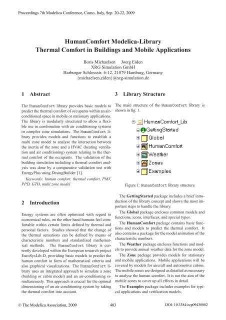
The ma<strong>in</strong> structure of the <strong>Human<strong>Comfort</strong></strong> library is<br />
shown <strong>in</strong> fig. 1.<br />
Figure 1: <strong>Human<strong>Comfort</strong></strong> library structure<br />
The Gett<strong>in</strong>gStarted package <strong>in</strong>cludes a brief <strong>in</strong>troduction<br />
of the library concept <strong>and</strong> shows the most important<br />
steps to h<strong>and</strong>le the library.<br />
The Global package encloses common models <strong>and</strong><br />
functions, icons, <strong>in</strong>terfaces, <strong>and</strong> special types.<br />
The <strong>Human<strong>Comfort</strong></strong> package conta<strong>in</strong>s basic functions<br />
<strong>and</strong> models to predict the thermal comfort. It<br />
also conta<strong>in</strong>s a package for the model animation of the<br />
characteristic numbers.<br />
The Weather package encloses functions <strong>and</strong> models<br />
to provide annual weather data for the zone model.<br />
The Zone package provides models for stationary<br />
<strong>and</strong> mobile applications. Mobile applications will be<br />
covered by models for aircraft <strong>and</strong> automotive cab<strong>in</strong>s.<br />
The mobile zones are designed as detailed as necessary<br />
to analyse the human comfort. It is not the aim of the<br />
mobile zones to cover up all effects <strong>in</strong> detail.<br />
The Examples package <strong>in</strong>cludes examples for typical<br />
applications <strong>and</strong> verification models.<br />
© The <strong>Modelica</strong> Association, 2009 403 DOI: 10.3384/ecp09430082
Proceed<strong>in</strong>gs 7th <strong>Modelica</strong> Conference, Como, Italy, Sep. 20-22, 2009<br />
4 Human <strong>Comfort</strong><br />
<strong>Thermal</strong> comfort is def<strong>in</strong>ed as that condition of m<strong>in</strong>d<br />
that expresses satisfaction with the thermal environment.<br />
Dissatisfaction may be caused by warm or cool<br />
discomfort of the body or may be caused by an unwanted<br />
cool<strong>in</strong>g or heat<strong>in</strong>g [2]. <strong>Thermal</strong> comfort st<strong>and</strong>ards<br />
are based on collected data from laboratory <strong>and</strong><br />
field studies which provide the necessary statistical<br />
data to def<strong>in</strong>e the conditions that a specified percentage<br />
of occupants will f<strong>in</strong>d thermally comfortable.<br />
The implemented thermal prediction models consider<br />
statistic <strong>and</strong> adaptive comfort models, based on<br />
the follow<strong>in</strong>g st<strong>and</strong>ards:<br />
• DIN EN ISO 7730 [2]<br />
• ASHRAE St<strong>and</strong>ard 55-2004 [3]<br />
• ISSO 74 [4]<br />
To predict the thermal comfort, it is necessary to<br />
consider the thermal factors: temperature, radiant temperature,<br />
humidity, <strong>and</strong> air velocity as well as the personal<br />
factors: activity (metabolic rate) <strong>and</strong> cloth<strong>in</strong>g <strong>in</strong>sulation.<br />
The relation between this factors are provided by the<br />
st<strong>and</strong>ards as mathematical formulated characteristic<br />
numbers.<br />
Us<strong>in</strong>g the characteristic numbers Predicted Mean<br />
Vote (PMV) <strong>and</strong> Predicted Percentage of Dissatisfied<br />
(PPD) the thermal comfort can be calculated.<br />
The local thermal discomfort will be considered by<br />
the Percentage of Discomfort (PD) <strong>and</strong> can be divided<br />
<strong>in</strong>to the follow<strong>in</strong>g sections:<br />
• Radiant temperature asymmetry<br />
• Draft<br />
• Vertical air temperature difference<br />
• Cool or warm wall<br />
• Cool or warm ceil<strong>in</strong>g<br />
• Cool or warm floors<br />
Adaptive thermal comfort consider the fact that occupants<br />
will tolerate a wider range of temperatures <strong>and</strong><br />
<strong>in</strong>ternal conditions when more control is allowed over<br />
their <strong>in</strong>ternal environment. The implementation of the<br />
ISSO 74 (Dutch <strong>Thermal</strong> <strong>Comfort</strong> Guidel<strong>in</strong>e) exp<strong>and</strong>s<br />
the<strong>Human<strong>Comfort</strong></strong> library with additional characteristic<br />
numbers <strong>and</strong> diagrams regard<strong>in</strong>g the adaptive thermal<br />
comfort.<br />
The operative <strong>in</strong>door temperature, the Adaptive<br />
Temperature Limits (ATG) <strong>and</strong> the annual characteristic<br />
numbers Weighted Temperature Exceed<strong>in</strong>g Hours<br />
© The <strong>Modelica</strong> Association, 2009 404<br />
(GTO), TO25 ◦ C <strong>and</strong> TO28 ◦ C (Operative Temperature<br />
Limits) cover up this adaptive thermal comfort.<br />
Figure 2: Diagram layer of the<strong>Human<strong>Comfort</strong></strong> model;<br />
<strong>in</strong>clud<strong>in</strong>g the functions <strong>and</strong> models for the PMV, PPD,<br />
<strong>and</strong> PD’s calculation, <strong>and</strong> the <strong>Human<strong>Comfort</strong></strong> adapter<br />
The characteristic numbers are pooled <strong>in</strong> one model<br />
named <strong>Human<strong>Comfort</strong></strong> (see fig. 2). The therefore<br />
established <strong>Human<strong>Comfort</strong></strong> adapter enables an easy<br />
<strong>in</strong>terface for the end-user. This allows a complete<br />
thermal comfort analysis by simply connect<strong>in</strong>g the<br />
<strong>Human<strong>Comfort</strong></strong> model to this adapter.<br />
4.1 Characteristic Numbers<br />
Calculation methods <strong>and</strong> the result<strong>in</strong>g characteristic<br />
numbers are provided <strong>in</strong> several <strong>in</strong>ternational st<strong>and</strong>ards<br />
([2], [3], [4]). The characteristic numbers are<br />
implemented as functions <strong>and</strong> models for a flexible<br />
use. The most important characteristic numbers are<br />
described <strong>in</strong> detail <strong>in</strong> the follow<strong>in</strong>g sections.<br />
4.1.1 Predicted Mean Vote (PMV)<br />
The PMV is an <strong>in</strong>dex that predicts the mean value of<br />
the votes of a large group of persons on the sevenpo<strong>in</strong>t<br />
thermal sensation scale [3]. It uses heat balance pr<strong>in</strong>ciples<br />
to relate the thermal <strong>and</strong> personal factors for thermal<br />
comfort to the average response of people on the<br />
sensation scale. The ideal range is between -0.5 <strong>and</strong><br />
+0.5 (neutral) (see fig. 3).
Proceed<strong>in</strong>gs 7th <strong>Modelica</strong> Conference, Como, Italy, Sep. 20-22, 2009<br />
PMV <strong>Comfort</strong><br />
+3 hot<br />
+2 warm<br />
+1 slightly warm<br />
0 neutral<br />
-1 slightly cool<br />
-2 cool<br />
-3 cold<br />
Figure 3: PMV <strong>and</strong> PPD visualization, screen shot of<br />
the Dymola model animation w<strong>in</strong>dow<br />
PMV = Predicted Mean Vote [−]<br />
PPD = Predicted Percentage of Dissatisfied [%]<br />
<strong>Thermal</strong> factors:<br />
Ta = ambient temperature [K]<br />
Tr = mean radiant temperature [K]<br />
vair = relative air velocity [m/s]<br />
pa = water vapour pressure [Pa]<br />
RH = relative humidity [%]<br />
Personal factors:<br />
CLO = thermal isolation of the cloth<strong>in</strong>g [clo = 0.155 · m 2 · K/W]<br />
M = metabolic rate [met = 58.15W/m 2 ]<br />
W = external work [W/m 2 ]<br />
Internal values of PMV function:<br />
Icl = thermal resistance of the cloth<strong>in</strong>g [m 2 · K/W]<br />
hc = convective heat transfer coefficient [W/m 2 · K]<br />
fcl = ratio of clothed body [−]<br />
HLx = heat loss factors [−]<br />
T S = thermal sensation transformation coefficient [−]<br />
The first step to determ<strong>in</strong>e PMV is the calculation of<br />
the thermal resistance of the cloth<strong>in</strong>g Icl <strong>and</strong> the ratio<br />
of clothed body fcl (see eq. 1 <strong>and</strong> 2).<br />
© The <strong>Modelica</strong> Association, 2009 405<br />
Icl = 0.155 ·CLO (1)<br />
�<br />
1.05+0.645 · Icl for Icl > 0.078<br />
fcl =<br />
1+1.29 · Icl for Icl ≤ 0.078<br />
It is necessary to iterate, due to hc = f(Tcl) <strong>and</strong> Tcl =<br />
f(hc,Tcl), see eq. 3 <strong>and</strong> 4. The allowed failure of the<br />
iteration process is 10 −9 .<br />
hc =<br />
�<br />
2.38 · |Tcl − Ta| 1 4 for 2.38 · |Tcl − Ta| 1 4 > 12.1 · √ vair<br />
12.1 · √ vair for 2.38 · |Tcl − Ta| 1 4 ≤ 12.1 · √ vair<br />
Tcl = 35.7 − 0.028 ·(M −W)<br />
−Icl ·[3.96 · 10−8 · fcl ·(T 4<br />
cl − T 4<br />
r )+ fcl · hc ·(Tcl − Ta)]<br />
The user has two options to describe the <strong>in</strong>put of<br />
the humidity. The first one is to use the water vapour<br />
pressure pa. The second option is to use the relative<br />
humidity RH. The follow<strong>in</strong>g equation describes the<br />
relation between pa <strong>and</strong> RH.<br />
�<br />
RH · 10 · e16.6536−4030.183/(ta+235) for pa = 0<br />
pa,<strong>in</strong>ternal =<br />
pa for pa > 0<br />
The calculations of all heat losses <strong>and</strong> the thermal<br />
sensation transformation coefficient are the last steps<br />
to determ<strong>in</strong>e the PMV (see eq. 6 to 12).<br />
(2)<br />
(3)<br />
(4)<br />
(5)<br />
T S = [0.303 · e −0.036·M + 0.028] (6)<br />
HL 1(sk<strong>in</strong>) = 3.05 · 0.001 ·(5733 − 6.99 ·(M −W) − Pa) (7)<br />
�<br />
0.42 ·(M −W − 58.15) for M −W > 58.15<br />
HL2(sweat) =<br />
0 for M −W ≤ 58.15<br />
HL 3(latent_respiration) = 1.7 · 0.00001 · M ·(5867 − pa) (9)<br />
(8)<br />
HL 4(dry_respiration) = 0.0014 · M ·(34 −ta) (10)<br />
HL5(radiation) = 3.96 · 0.00000001 · fcl ·(T 4 4<br />
cl − Tr ) (11)<br />
HL 6(convection) = fcl · hc ·(tcl −ta) (12)<br />
The f<strong>in</strong>al step is the calculation of the PMV.<br />
PMV = T S ·(M −W − HL1 − HL2 − HL3 − HL4 − HL5 − HL6) (13)<br />
The PMV is the basis of the PPD <strong>and</strong> the GTO.<br />
4.1.2 Predicted Percentage of Dissatisfied (PPD)<br />
The PPD is an <strong>in</strong>dex that establishes a quantitative prediction<br />
of the percentage of thermally dissatisfied people<br />
determ<strong>in</strong>ed from PMV (see eq. 14 <strong>and</strong> fig. 4) [3].<br />
PPD = 100 − 95 · e −0.03353·PMV 4 −0.2179·PMV 2<br />
(14)
Proceed<strong>in</strong>gs 7th <strong>Modelica</strong> Conference, Como, Italy, Sep. 20-22, 2009<br />
Figure 4: Correlation between PMV <strong>and</strong> PPD<br />
4.1.3 Weighted Temperature Exceed<strong>in</strong>g Hours<br />
(GTO)<br />
The GTO-method which is based on the analyticalPMV<br />
model is an annual characteristic number.<br />
In the GTO-method the hours dur<strong>in</strong>g which the calculated<br />
or actual PMV exceeds the PMV-limit of +0.5<br />
are weighted proportional to the PPD. With this, a temperature<br />
that results <strong>in</strong> a PPD of 20% dur<strong>in</strong>g 1 hour<br />
will be weighted twice as severe as a temperature that<br />
results <strong>in</strong> 10% dissatisfied occupants [4]. When the<br />
PMV has a value of 0.5 (PPD=10) the weight<strong>in</strong>g factor<br />
is 1.0, see tab. 1:<br />
PMV PPD Weight<strong>in</strong>g factor<br />
0 5 0.0<br />
0.5 10 1.0<br />
0.7 15 1.5<br />
1.0 26 2.6<br />
Table 1: Correlation of PMV, PPD, <strong>and</strong> the GTO<br />
weight<strong>in</strong>g factor [4]<br />
The GTO will be calculated every 3600 seconds, by<br />
us<strong>in</strong>g the actual PMV value as the <strong>in</strong>put. This is implemented<br />
by us<strong>in</strong>g the <strong>Modelica</strong> sample function, see<br />
source code 1. The govern<strong>in</strong>g equations for the GTO<br />
are described <strong>in</strong> eq. 15- 17.<br />
PPDhour = 100 − 95 · e −0.03353·PMV 4 hour −0.2179·PMV 2 hour (15)<br />
� PPDhour<br />
GTOhour = 10 f or PMV ≥ 0.5<br />
0 for PMV < 0.5<br />
8760<br />
GTO = ∑ GTOhour<br />
hour=1<br />
PMVhour = Predicted Mean Vote of current hour [−]<br />
PPDhour = Predicted Percent. of Dissatisfied of curr. hour [%]<br />
GTOhour = Weighted temperature of current hour [−]<br />
GTO = Weighted temperature Exceed<strong>in</strong>g Hours [−]<br />
(16)<br />
(17)<br />
© The <strong>Modelica</strong> Association, 2009 406<br />
The follow<strong>in</strong>g source code shows the implementation<br />
of the GTO-Method <strong>in</strong> <strong>Modelica</strong>.<br />
h o u r _ s t e p = f l o o r ( t i m e / 3 6 0 0 ) ;<br />
hour = t i m e / 3 6 0 0 ;<br />
day = hour / 2 4 ;<br />
when i n i t i a l ( ) then<br />
s t a r t T i m e = t i m e ;<br />
end when ;<br />
der ( PMV_<strong>in</strong>t ) = PMV;<br />
PMV_mean = noEvent ( i f t i m e − s t a r t T i m e > 0 then<br />
PMV_<strong>in</strong>t / ( t i m e − s t a r t T i m e ) e l s e PMV) ;<br />
when sample ( 0 , 3600) then<br />
PMV_<strong>in</strong>t_step = PMV_<strong>in</strong>t ;<br />
PMV_<strong>in</strong>t_step_pre = pre ( PMV_<strong>in</strong>t_step ) ;<br />
PMV_mean_h = noEvent ( i f t i m e − s t a r t T i m e > 0 then<br />
( PMV_<strong>in</strong>t_step − PMV_<strong>in</strong>t_step_pre ) / ( 3 6 0 0 ) e l s e PMV_<strong>in</strong> ) ;<br />
i f abs ( PMV_<strong>in</strong> ) >= 0 . 5 then<br />
GTO = pre (GTO) + PPD ( PMV_<strong>in</strong> ) / 1 0 ;<br />
e l s e<br />
GTO = pre (GTO) ;<br />
end i f ;<br />
end when ;<br />
Source Code 1: <strong>Modelica</strong> code of the GTOmodel<br />
The <strong>in</strong> [4] given annual limit of 150 will be considered<br />
<strong>in</strong> the analyses of the GTO. Fig. 5 describes the<br />
correlation between the hourly values of PMV, PPD<br />
<strong>and</strong> GTO. In this theoretical case the PMV <strong>in</strong>crease<br />
from -3 to +3 <strong>in</strong> a time period of 60h. The grey area<br />
<strong>in</strong> the graph shows a constant GTO value with<strong>in</strong> the<br />
PMV limit from -0.5 to +0.5.<br />
Figure 5: Correlation of the hourly values of PMV,<br />
PPD, <strong>and</strong> GTO by an <strong>in</strong>creas<strong>in</strong>g PMV from -3 to +3<br />
4.2 Other Characteristic Numbers<br />
The follow<strong>in</strong>g characteristic numbers are def<strong>in</strong>ed<br />
<strong>in</strong> the st<strong>and</strong>ards <strong>and</strong> are implemented <strong>in</strong> the<br />
<strong>Human<strong>Comfort</strong></strong> library, but will not be described <strong>in</strong><br />
this paper <strong>in</strong> detail.<br />
• DR - Draught Rat<strong>in</strong>g [2]<br />
• PD Due to Radiant Asymmetry [2]<br />
– PD Due to Cool Wall<br />
– PD Due to Warm Wall
Proceed<strong>in</strong>gs 7th <strong>Modelica</strong> Conference, Como, Italy, Sep. 20-22, 2009<br />
– PD Due to Cool Ceil<strong>in</strong>g<br />
– PD Due to Warm Ceil<strong>in</strong>g<br />
• PD Due to Cool or Warm Floors [2]<br />
• PD Due to Vertical Air Temperature Difference [2]<br />
• ATG - Adaptive Temperature Limits [4]<br />
• TO - Operative Temperature Limits [4]<br />
• DAR - Limits on Temperature Drifts <strong>and</strong> Ramps [3]<br />
5 Zones<br />
The zones are separated <strong>in</strong>to models for mobile <strong>and</strong><br />
stationary applications. The stationary applications are<br />
s<strong>in</strong>gle rooms or small build<strong>in</strong>gs. The mobile applications<br />
will be automotive or aircraft cab<strong>in</strong>s. Each application<br />
can be comb<strong>in</strong>ed with the weather or Human-<br />
<strong>Comfort</strong> module (see fig. 6).<br />
Figure 6: One room model with a connected weather<br />
<strong>and</strong><strong>Human<strong>Comfort</strong></strong> model<br />
The ma<strong>in</strong> features of the zone models are:<br />
Internal heat radiation between visible surfaces.<br />
The RadiationExchangeApproximated model considers<br />
the heat exchange due to heat radiation of surfaces<br />
to each other. The external solar radiation<br />
through the w<strong>in</strong>dows <strong>and</strong> the <strong>in</strong>ternal heater radiation<br />
will be considered as well. Therefore the heat emissions<br />
of all surfaces, def<strong>in</strong>ed by their areas, temperatures<br />
<strong>and</strong> long wave emissions coefficients will be collected<br />
<strong>in</strong> a virtual heat pool. The solar radiation, def<strong>in</strong>ed<br />
by the short wave emission coefficient, <strong>and</strong> the<br />
heater radiation are also collected <strong>in</strong> the virtual heat<br />
pool. The absorbed heat flows of the surfaces are def<strong>in</strong>ed<br />
by their areas, temperatures <strong>and</strong> absorption coefficients.<br />
The schematic of the virtual heat pool is<br />
shown <strong>in</strong> fig. 7.<br />
The solar radiation reflection <strong>and</strong> back reflection on<br />
all surfaces will affect the f<strong>in</strong>al amount of the solar radiation<br />
<strong>in</strong>to the virtual heat pool. The mean absorption<br />
rate of a zone is calculated with the absorption ratio of<br />
© The <strong>Modelica</strong> Association, 2009 407<br />
Figure 7: Schematic of the virtual heat pool implemented<br />
<strong>in</strong> the RadiationExchangeApproximated<br />
model<br />
all surfaces <strong>and</strong> a reflection parameter. The reflection<br />
parameter def<strong>in</strong>es the mean number of <strong>in</strong>ternal reflections<br />
of all sun rays, before they leave the zone. The<br />
source code 2 presents the implementation of the solar<br />
reflection calculation.<br />
Q _ t o t a l = sum ( Q_out [ i ] f o r i <strong>in</strong> 1 : 1 2 )<br />
+ G _ t o t a l ∗abs_mean + Q _ r a d i a t o r ;<br />
S o l a r G a i n = G _ t o t a l ∗ a b s _ t o t a l ;<br />
abs_mean=sum ( A_abs [ i ] f o r i <strong>in</strong> 1 : 1 2 ) / A _ t o t a l ;<br />
emission_mean =sum ( A_emi [ i ] f o r i <strong>in</strong> 1 : 1 2 ) / A _ t o t a l ;<br />
f a c t o r [ 1 ] = 1 ;<br />
a b s o r p i o n _ f a c t o r [ 1 ] = abs_mean∗ f a c t o r [ 1 ] ;<br />
f o r i <strong>in</strong> 2 : 1 : 1 0 loop<br />
f a c t o r [ i ]= m<strong>in</strong> ( max( r e f l e c t i o n s −i +1 ,0) , 1 ) ;<br />
a b s _ f a c t o r [ i ]=(1 −sum ( a b s _ f a c t o r [ x ] f o r x <strong>in</strong> 1 : i −1) )<br />
∗ abs_mean∗ f a c t o r [ i ] ;<br />
end f o r ;<br />
a b s _ t o t a l =sum ( a b s _ f a c t o r ) ;<br />
f o r i <strong>in</strong> 1 : 1 : 1 2 loop<br />
i f A[ i ] < eps then<br />
Q_out [ i ] = 0<br />
e l s e<br />
Q_out [ i ] =( e m i s s i o n [ i ]∗ sigma∗A[ i ]∗T [ i ] ^ 4 ) ;<br />
end i f ;<br />
Q_<strong>in</strong> [ i ] = Q _ t o t a l / A _ t o t a l ∗A[ i ]∗ abs [ i ] / abs_mean ;<br />
A_abs [ i ]=A[ i ]∗ abs [ i ] ;<br />
A_emi [ i ]=A[ i ]∗ e m i s s i o n [ i ] ;<br />
end f o r ;<br />
Source Code 2: <strong>Modelica</strong> code of the solar refection.<br />
This virtual heat pool method is an approximation<br />
of the exact calculation of the heat radiation exchange.<br />
To prove the <strong>Human<strong>Comfort</strong></strong> approach, the model was<br />
validated aga<strong>in</strong>st the EnergyPlus program, which uses<br />
the Hottel Grey Interchange Method. This method is<br />
an exact formulation of radiant heat transfer with<strong>in</strong> an<br />
enclosure of grey diffuse surfaces [5].<br />
The validation shows that the surface <strong>and</strong> mean radiant<br />
temperatures, calculated with the <strong>Human<strong>Comfort</strong></strong><br />
library, are with<strong>in</strong> acceptable limits.<br />
With regard to an annual simulation of a complex
Proceed<strong>in</strong>gs 7th <strong>Modelica</strong> Conference, Como, Italy, Sep. 20-22, 2009<br />
build<strong>in</strong>g, the approximated radiation model of the<br />
<strong>Human<strong>Comfort</strong></strong> library provides a fast <strong>and</strong> sufficient<br />
method to determ<strong>in</strong>e the heat radiation exchange.<br />
Control volume with energy <strong>and</strong> mass balance.<br />
The <strong>Human<strong>Comfort</strong></strong> library provides two control volumes.<br />
AControlVolumeAir model for the <strong>in</strong>door air<br />
with heat <strong>and</strong> flow ports, us<strong>in</strong>g the <strong>Modelica</strong>_Media<br />
moist air media model, <strong>and</strong> theControlVolumeWater<br />
model for water flows <strong>in</strong> heat<strong>in</strong>g cycles, fitted to improve<br />
<strong>in</strong>compressible flows.<br />
Multi-layer wall model. The wall models considers<br />
the heat conduction <strong>and</strong> convection at the <strong>in</strong>- <strong>and</strong> outside.<br />
The <strong>in</strong>ternal <strong>and</strong> external radiation absorption<br />
as well as the <strong>in</strong>ternal heat radiation will be considered.<br />
Every layer has a homogeneous mass to store<br />
thermal energy. It is also possible to def<strong>in</strong>e the orientation<br />
of the wall to the sun. The wall model <strong>in</strong>put is a<br />
record which <strong>in</strong>cludes a parameter matrix. The parameters<br />
def<strong>in</strong>e the conductivity, thermal capacity, density,<br />
surface area, <strong>and</strong> thickness for every layer. The<br />
<strong>Human<strong>Comfort</strong></strong> library conta<strong>in</strong>s severals pre-designed<br />
wall records, ready to use. In addition, it is possible to<br />
connect a heat<strong>in</strong>g system (e.g. floor heat<strong>in</strong>g) to a s<strong>in</strong>gle<br />
layer <strong>in</strong> the wall model via heat flow connectors.<br />
Air exchange due to pressure <strong>and</strong> density differences<br />
between adjacent rooms with doors or other<br />
open<strong>in</strong>gs. The WallFlowDensityPressure model<br />
def<strong>in</strong>es the air exchange between two rooms. The mass<br />
flow rate depends on pressure <strong>and</strong> density differences<br />
<strong>and</strong> the size of the open<strong>in</strong>g (see fig. 8). The open<strong>in</strong>g<br />
size can be varied dur<strong>in</strong>g the simulation to consider<br />
realistic office build<strong>in</strong>g behavior.<br />
Figure 8: Influence of pressure <strong>and</strong> density for air exchange<br />
between two rooms [6]<br />
The govern<strong>in</strong>g equation for the result<strong>in</strong>g mass flow<br />
rate are described as follows:<br />
˙mdensity = W<br />
3 · H 3 2 · μ0 ·<br />
�<br />
g · Δρ<br />
· Nodoors<br />
ρm<br />
(18)<br />
© The <strong>Modelica</strong> Association, 2009 408<br />
˙mpressure =<br />
�<br />
Δp · 2<br />
ρm · ζ · W · H · ρm · Nodoors<br />
2<br />
˙m1 = ˙mpressure − ˙mdensity<br />
˙m2 = ˙mpressure + ˙mdensity<br />
H = height [m]<br />
W = weight [m]<br />
g = gravity [m/s 2 ]<br />
Δp = pressure difference [Pa]<br />
Δρ = density difference [kg/m 3 ]<br />
ρm = mean density [kg/m 3 ]<br />
Nodoors = number of doors [−]<br />
μ0 = coefficient of airflow [−]<br />
ζ = coefficient of friction [−]<br />
(19)<br />
(20)<br />
(21)<br />
Air exchange between zone <strong>and</strong> ambient. Air exchange<br />
of azone model <strong>and</strong> the ambient occurs due to<br />
variable <strong>in</strong>door air pressure effected by <strong>in</strong>ternal temperature<br />
changes. This air exchange is <strong>in</strong>verse formulated,<br />
by sett<strong>in</strong>g the pressure difference to zero.<br />
The correspond<strong>in</strong>g mass flow will be calculated by the<br />
model. This results <strong>in</strong> an efficient code that significantly<br />
reduces the computation time of an annual simulation.<br />
Dynamic calculation of heat transfer coefficients<br />
for <strong>in</strong>door <strong>and</strong> outdoor surfaces. Three calculation<br />
methods are implemented for the convective heat<br />
transfer. The first method describes the heat transfer<br />
coefficient as a constant parameter. The second<br />
method calculates the heat transfer coefficient depend<strong>in</strong>g<br />
on the temperature difference <strong>and</strong> the surface<br />
roughness. The third one def<strong>in</strong>es the heat transfer coefficient<br />
depend<strong>in</strong>g on the temperature difference, the<br />
surface roughness, the w<strong>in</strong>d speed, <strong>and</strong> the w<strong>in</strong>d direction.<br />
The correlation of the second <strong>and</strong> third method<br />
are described <strong>in</strong> [1].<br />
W<strong>in</strong>dow models with pre-designed w<strong>in</strong>dow property<br />
records. The W<strong>in</strong>dow model considers two effects,<br />
the reflection of solar radiation <strong>and</strong> the thermal<br />
conductivity. The total solar ga<strong>in</strong> through w<strong>in</strong>dows is<br />
considered by parameters based on the fraction of solar<br />
heat ga<strong>in</strong> that passes through compared to either the<br />
<strong>in</strong>cident solar radiation or the transmission of a reference<br />
glaz<strong>in</strong>g type. They are given as a decimal value<br />
<strong>in</strong> the range 0-1. The <strong>Human<strong>Comfort</strong></strong> library use the<br />
Solar Heat Ga<strong>in</strong> Coefficient (SHGC) or the G-Value.
Proceed<strong>in</strong>gs 7th <strong>Modelica</strong> Conference, Como, Italy, Sep. 20-22, 2009<br />
Internal time table based heat source due to equipment<br />
<strong>and</strong> light sources. The <strong>in</strong>fluence of the variable<br />
operat<strong>in</strong>g time of the equipment is an important<br />
factor for the load <strong>and</strong> energy analyses calculations.<br />
The operat<strong>in</strong>g time can be set for every hour of a day.<br />
The follow<strong>in</strong>g equation describes the implantation:<br />
˙Qequipment = ˙Qheat_source · ftime_table_equ<br />
˙Qheat_source = heat flow due to equipment [W]<br />
˙Qequipment = total heat flow due to equipment [W]<br />
ftime_table_equ = ratio of active equipment [−]<br />
(22)<br />
Internal time table based heat- <strong>and</strong> water vapour<br />
sources due to occupants. The heat <strong>and</strong> vapour<br />
emission depends on the air temperature, the activity<br />
level, <strong>and</strong> the presence of the occupants. The Internal-<br />
Loads model generates heat flow <strong>and</strong> humidity flow<br />
<strong>in</strong>to the room. Eq. 23- 25 describe the correlation def<strong>in</strong>ed<br />
<strong>in</strong> [1].<br />
MET = met · Ask<strong>in</strong><br />
˙Qmet_rate = 6.461927+0.946892 · MET + 0.0000255737 · MET 2<br />
+7.139322 · Tair − 0.0627909 · Tair · MET<br />
+0.0000589172 · Tair · MET 2 − 0.19855 · T 2<br />
air<br />
+0.000940018 · T 2<br />
air · MET<br />
−0.00000149532 · MET 2 · T 2<br />
air<br />
˙Qoccupant = ˙Qmet_rate · occ · ftime_table_occ<br />
(23)<br />
(24)<br />
(25)<br />
met = spec. metabolic rate due to sk<strong>in</strong> surface [W/m 2 ]<br />
MET = metabolic rate [W]<br />
Ask<strong>in</strong> = sk<strong>in</strong> surface [m 2 ]<br />
˙Qmet_rate = metabolic rate [W]<br />
Tair = <strong>in</strong>door air temperature [ ◦ C]<br />
˙Qoccupant = total heat prod. acc. to occupants [W]<br />
occ = number of occupants [−]<br />
ftime_table_occ = ratio of present occupants [−]<br />
[7] def<strong>in</strong>es the vapour emission of the occupants depend<strong>in</strong>g<br />
on the air temperature <strong>and</strong> the activity as a<br />
matrix, see tab. 2.<br />
Air temperature ◦ C 18 20 22 23 24 25<br />
˙mvapor (120 W) g/h 35 35 40 50 60 60<br />
˙mvapor (190 W) g/h 95 110 125 135 140 145<br />
˙mvapor (270 W) g/h 165 185 215 225 230 240<br />
Table 2: Vapor emission of occupants depend<strong>in</strong>g on<br />
temperature <strong>and</strong> activity level def<strong>in</strong>ed by [7]<br />
Simplified HVAC components. The<br />
<strong>Human<strong>Comfort</strong></strong> library <strong>in</strong>cludes simplified HVAC<br />
components def<strong>in</strong>ed by [8](e.g. pump <strong>and</strong> radiator),<br />
which are compatible with the <strong>Modelica</strong>_Fluid library.<br />
© The <strong>Modelica</strong> Association, 2009 409<br />
The radiator model consists of a control volume, a<br />
pressure drop model, <strong>and</strong> a heat transfer model. The<br />
<strong>in</strong>put of the pressure drop model can be either a zeta<br />
value or a Kv value. Two different heat transfer models<br />
are available <strong>and</strong> described <strong>in</strong> the follow<strong>in</strong>g:<br />
1. The heat flow is calculated by a heat transfer coefficient,<br />
the heat exchange surface, <strong>and</strong> the <strong>in</strong>bound<br />
water <strong>and</strong> air temperature difference. The model is<br />
discretized to <strong>in</strong>crease the precission.<br />
˙Q = k · A ·(Twater − Tair) (26)<br />
˙Q = radiator heat flow to the room [W]<br />
k = heat transfer coefficient [W/m 2 · K]<br />
A = heat transfer area [m 2 ]<br />
Twater = water temperature [K]<br />
Tair = air temperature [K]<br />
2. The radiator heat flow is calculated by an approximat<strong>in</strong>g<br />
function, which uses a nom<strong>in</strong>al characteristic<br />
of existent radiators. The <strong>in</strong>put values for nom<strong>in</strong>al<br />
conditions at the operat<strong>in</strong>g po<strong>in</strong>t are def<strong>in</strong>ed by radiator<br />
manufacturers. These values are available by us<strong>in</strong>g<br />
pre-designed records for severals radiator types.<br />
˙Qn<br />
˙mn =<br />
(T<strong>in</strong>,n − Tout,n) · cpn<br />
ΔTm,n = T<strong>in</strong>,n + Tout,n<br />
2<br />
− Tair,n<br />
(27)<br />
(28)<br />
ΔTmax = max((T<strong>in</strong> − Tair) − ΔTout,m<strong>in</strong>),0) (29)<br />
�<br />
L ·(T<strong>in</strong>,n − Tout,n) ·(T<strong>in</strong> − Tair)<br />
ΔT = m<strong>in</strong><br />
·<br />
T<strong>in</strong>,n − Tair,n<br />
˙mn<br />
˙m ,ΔTmax<br />
�<br />
� �<br />
T<strong>in</strong> +(T<strong>in</strong> − ΔT)<br />
ΔTm = max<br />
− Tair,0<br />
2<br />
� �nexp ΔTm<br />
f1 =<br />
ΔTm,n<br />
f5 = ( p0<br />
)<br />
pair<br />
0.75<br />
˙Q<br />
L · f1<br />
= ˙Qn ·<br />
f2 · f3 · f4 · f5<br />
˙Qn = nom<strong>in</strong>al heat flow [W]<br />
˙mn = nom<strong>in</strong>al mass flow [kg/s]<br />
cpn = nom<strong>in</strong>al thermal capacity [J/kg · K]<br />
T<strong>in</strong>,n = nom<strong>in</strong>al <strong>in</strong>bound water temperature [ ◦ C]<br />
Tout,n = nom<strong>in</strong>al outbound water temperature [ ◦ C]<br />
Tair,n = nom<strong>in</strong>al air temperature [ ◦ C]<br />
˙Q = heat flow [W]<br />
˙m = mass flow [kg/s]<br />
T<strong>in</strong> = <strong>in</strong>bound water temperature [ ◦ C]<br />
Tout = outbound water temperature [ ◦ C]<br />
Tair = air temperature [ ◦ C]<br />
ΔTm,n = mean nom<strong>in</strong>al temperature difference [ ◦ C]<br />
ΔTmax = maximal temperature difference [ ◦ C]<br />
ΔTout,m<strong>in</strong> = m<strong>in</strong>imal outlet temperature difference [ ◦ C]<br />
L = radiator length [m]<br />
nexp = radiator exponent [−]<br />
f1 = excess temperature factor [−]<br />
f2 = temperature splay factor [−]<br />
f3 = correction factor - type of connection [−]<br />
f4 = correction factor - type of cover [−]<br />
f5 = correction factor - atmospheric pressure [−]<br />
(30)<br />
(31)<br />
(32)<br />
(33)<br />
(34)
Proceed<strong>in</strong>gs 7th <strong>Modelica</strong> Conference, Como, Italy, Sep. 20-22, 2009<br />
Mean radiant temperature. Three different functions<br />
are implemented to calculate the mean radiant<br />
temperature of a cubical room with six sides.<br />
1. The mean_T_MRT function sets the mean surface<br />
temperature to the mean radiant temperature [1].<br />
TMRT = ∑x i=1 Ti<br />
x<br />
Figure 9: Diagram layer of the room model<br />
(35)<br />
2. The mean_T_to_A_MRT function calculates surface<br />
weighted mean radiation temperatures [1].<br />
TMRT = ∑x i=1 Ai · Ti<br />
ATotal<br />
TMRT = Mean Radiant Temperature [ ◦ C]<br />
T = Temperature [ ◦ C]<br />
A = Area [ ◦ C]<br />
(36)<br />
3. The deltaT_max_MRT function calculates the<br />
mean radiation temperature depend<strong>in</strong>g on the mean<br />
surface temperature <strong>and</strong> the temperature that has the<br />
highest difference to the mean value Tmax,di f . The<br />
<strong>Human<strong>Comfort</strong></strong> library use Tmax,di f as an extreme<br />
value, because normally the surface that is next to the<br />
occupant would be used as the maximal value. But<br />
the model has no geometric data of the position of the<br />
occupant so the maximal possible value will be used.<br />
TMRT = Tmax,di f + Tmean<br />
2<br />
(37)<br />
© The <strong>Modelica</strong> Association, 2009 410<br />
Fig. 9 shows a ma<strong>in</strong> model of the zone package, the<br />
room model. It consists, amongst others, an air control<br />
volume (1), a radiation exchange model (1), <strong>in</strong>ternal<br />
heat <strong>and</strong> vapour sources (1), six multi-layer wall models<br />
(2), several heat <strong>and</strong> fluid connectors (3), a weather<br />
connector (4), <strong>and</strong> a human comfort adapter (5).<br />
6 Weather<br />
The weather package provides severals ambient conditions<br />
by read<strong>in</strong>g an external text file.<br />
• Ambient <strong>and</strong> temperature, pressure <strong>and</strong> humidity<br />
• Global, direct <strong>and</strong> diffuse radiation to a tiled surface<br />
• Azimuth (north based) <strong>and</strong> Zenith<br />
• Sun position <strong>and</strong> radiation, depend<strong>in</strong>g on the location<br />
7 Verification <strong>and</strong> Validation<br />
An essential part of the library development is the verification<br />
<strong>and</strong> validation. The verification process of the<br />
<strong>Human<strong>Comfort</strong></strong> models <strong>and</strong> functions was done <strong>in</strong> accordance<br />
with the implemented st<strong>and</strong>ards.<br />
A comparative validation test was done by compar<strong>in</strong>g<br />
the <strong>Human<strong>Comfort</strong></strong> library with the Energy-<br />
Plus/DesignBuilder program [1], which is validated<br />
accord<strong>in</strong>g to ANSI/ASHRAE St<strong>and</strong>ard 140-2004.
Proceed<strong>in</strong>gs 7th <strong>Modelica</strong> Conference, Como, Italy, Sep. 20-22, 2009<br />
Therefore a two room test model was established<br />
(see fig. 10).<br />
Figure 10: Graphical representation of the<br />
<strong>Human<strong>Comfort</strong></strong> test model for the validation<br />
The rooms have an open<strong>in</strong>g <strong>in</strong> the adjacent wall<br />
to consider an air exchange. No heat<strong>in</strong>g system was<br />
implemented to generate higher temperature differences<br />
between the rooms. The rooms have one occupant<br />
with a normal metabolic rate for office activities<br />
(1met). The north room has two w<strong>in</strong>dows, one orientated<br />
to the west <strong>and</strong> one to the east. The south room<br />
has one w<strong>in</strong>dow orientated to the south. The ambient<br />
condition are def<strong>in</strong>ed by the weather data, which references<br />
to the city of Hamburg. The graphical representation<br />
of the two room test model is shown <strong>in</strong> fig. 11.<br />
Figure 11: Graphical representation of the Design-<br />
Builder test model for the validation<br />
As the operative, mean radiant, <strong>and</strong> the <strong>in</strong>door air<br />
temperature were important factors for thermal comfort,<br />
their simulation results will be discussed. Fig. 12<br />
shows the simulation results of the north room operative<br />
<strong>and</strong> outside temperature over a time period of one<br />
year.<br />
© The <strong>Modelica</strong> Association, 2009 411<br />
Figure 12: Simulation results of the operative <strong>and</strong> outside<br />
temperature from the <strong>Human<strong>Comfort</strong></strong> library <strong>and</strong><br />
DesignBuilder of the north room<br />
Tab. 3 shows the mean values of the different temperatures,<br />
the deviation to each other <strong>and</strong> the mean of<br />
the absolute deviations.<br />
mean value HC DB dev. abs. dev.<br />
unit ◦ C ◦ C ◦ C ◦ C<br />
<strong>in</strong>door temperature 13.058 12.633 0.425 0.625<br />
operative temperature 13.215 12.816 0.399 0.611<br />
mean radiant temperature 13.372 13.000 0.372 0.620<br />
Table 3: Selected temperatures of the north room<br />
The maximum deviations occurs <strong>in</strong> the summer<br />
dur<strong>in</strong>g rapidly decreas<strong>in</strong>g outside temperatures. The<br />
mean deviation of the operative temperature amounts<br />
to 0.399 ◦ C with an absolute deviation of 0.611 ◦ C. The<br />
mean deviation of the <strong>in</strong>door air temperature amounts<br />
to 0.425 ◦ C with a maximal deviation of 2.4 ◦ C at 11th<br />
of June.<br />
Fig. 13 depicts the relative humidity of the north<br />
room dur<strong>in</strong>g the course of the year. The occurr<strong>in</strong>g deviations<br />
can be expla<strong>in</strong>ed by the fact that the relative<br />
humidity depends on the temperature.<br />
Figure 13: Simulation results of the relative humidity
Proceed<strong>in</strong>gs 7th <strong>Modelica</strong> Conference, Como, Italy, Sep. 20-22, 2009<br />
The result<strong>in</strong>g PMV of the north room is shown <strong>in</strong><br />
fig. 14. Due to the fact that the PMV depends on the<br />
temperature <strong>and</strong> relative humidity the deviations behave<br />
analogous.<br />
Figure 14: Simulation results of the PMV from<br />
<strong>Human<strong>Comfort</strong></strong> library <strong>and</strong> DesignBuilder of the north<br />
room<br />
Tab. 4 displaces the mean values of the PMV, the<br />
deviation to each other <strong>and</strong> the mean of the absolute<br />
deviations.<br />
mean values HC DB deviation absolute dev.<br />
PMV -2.62 -2.67 -0.047 0.151<br />
Table 4: Mean values <strong>and</strong> their deviations of the PMV<br />
from the north room<br />
The comparative validation test reveals that the<br />
results predicted by the <strong>Human<strong>Comfort</strong></strong> library are<br />
with<strong>in</strong> the range of EnergyPlus/DesignBuilder.<br />
8 Conclusion<br />
The <strong>Human<strong>Comfort</strong></strong> library enables the prediction of<br />
thermal comfort <strong>in</strong> zone models. All relevant characteristic<br />
numbers, described <strong>in</strong> the st<strong>and</strong>ards, are implemented.<br />
The validations shows that the stationary<br />
zone model is <strong>in</strong> the range with another accurate energy<br />
simulation program on the market. The library<br />
development is still go<strong>in</strong>g on. The complete implementation<br />
of the mobile application will be f<strong>in</strong>ished<br />
until the end of the EuroSysLib-D project.<br />
© The <strong>Modelica</strong> Association, 2009 412<br />
Acknowledgement<br />
The <strong>Human<strong>Comfort</strong></strong> library is developed with<strong>in</strong> the<br />
European research project EuroSysLib-D funded by<br />
German Federal M<strong>in</strong>istry of Education <strong>and</strong> Research<br />
(promotional reference 01IS07022B). The project has<br />
been started <strong>in</strong> October 2007 <strong>and</strong> will end <strong>in</strong> March<br />
2010. The authors bear the sole responsibility for the<br />
content of this publication.<br />
References<br />
[1] US Department of Energy. EnergyPlus - Eng<strong>in</strong>eer<strong>in</strong>g<br />
Reference, June 2007.<br />
[2] DIN EN ISO 7730. Ergonomics of the thermal<br />
environment - Analytical determ<strong>in</strong>ation <strong>and</strong> <strong>in</strong>terpretation<br />
of thermal comfort us<strong>in</strong>g calculation of<br />
the PMV <strong>and</strong> PPD <strong>in</strong>dices <strong>and</strong> local thermal comfort<br />
criteria. Beuth Verlag GmbH, 2005.<br />
[3] ASHRAE St<strong>and</strong>ard 55-2004. <strong>Thermal</strong> Environmental<br />
Conditions for Human Occupancy, January<br />
2004.<br />
[4] A.C. van der L<strong>in</strong>den A.C. Boerstra W. Plokker<br />
A.K. Raue, S.R. Kurvers. Dutch <strong>Thermal</strong> <strong>Comfort</strong><br />
Guidel<strong>in</strong>es from Weighted Temperature Exceed<strong>in</strong>g<br />
Hours Towards Adaptive Temperature Limit,<br />
2004.<br />
[5] Str<strong>and</strong> Pedersen. Model<strong>in</strong>g Radiant Systems <strong>in</strong> an<br />
Integrated Heat Balance Based Energy Simulation<br />
Program. ASHRAE Transactions, 2002.<br />
[6] Frank Meyer zur Heide. Energiee<strong>in</strong>sparung und<br />
Komfortgew<strong>in</strong>n. CCI Pr<strong>in</strong>t, 2005.<br />
[7] Schramek Recknagel, Sprenger. Taschenbuch für<br />
Heizung und Klimatechnik. Oldenbourg Industrieverlag,<br />
2005.<br />
[8] Bernd Glück. Strahlungsheizung - Theorie und<br />
Praxis. C.F. Müller Verlag Heidelberg, 1982.