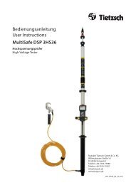
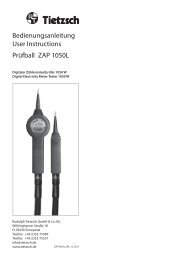
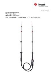
Bedienungsanleitung ZAP 350L - bei Tietzsch
Bedienungsanleitung ZAP 350L - bei Tietzsch
Bedienungsanleitung ZAP 350L - bei Tietzsch

Create successful ePaper yourself
Turn your PDF publications into a flip-book with our unique Google optimized e-Paper software.
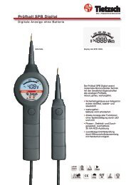
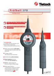
4.3 Voltage tests and polarity<br />
Attention!<br />
The maximum allowable on-time is 30 s (exception:<br />
when charging the device at a 230 V socket, see 4.7).<br />
Note!<br />
When the push-buttons are not pressed the Prüfball<br />
has a high internal resistance. In extreme cases,<br />
indication of inductive or capacitive voltages may<br />
occur which disappears when both push-buttons<br />
are pressed.<br />
Connect securely both test prods to the test point.<br />
Depending on voltage level, the red LED lights up<br />
at > 50 V, 120 V. The device selects automatically<br />
the correct voltage type (AC/DC), indicates voltage<br />
in “V” at the display and the bargraph. The flashing<br />
symbol “OL” warns against voltages outside the<br />
rated voltage range. Then testing must be stopped.<br />
Polarity<br />
Type of voltage is indicated by the symbols “~” and<br />
“-“. No symbol appears when the test prod marked<br />
„+“ is applied to plus of a d.c. voltage. When its<br />
applied to minus, the value is preceded with a “-”.<br />
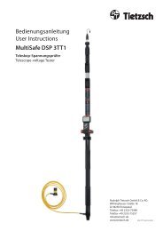
4.4 Phase and phase sequence test<br />
These tests can only be performed without pushbutton<br />
actuation.<br />
Attention!<br />
During these tests the device must be hold tightly<br />
by its handles. It is possible to wear insulating<br />
gloves.<br />
Note:<br />
Tests work only in grounded a.c. voltage systems<br />
with voltages of approx. 165 V or more against<br />
ground.<br />
Phase test<br />
The phase conductor is identified by applying the<br />
test electrode marked “+” to the conductor and by<br />
clasping the handle of the display part at the same<br />
time. When the conductor is energized, “POL” is<br />
indicated at the display.<br />
Phase sequence tests<br />
To determine the phase sequence between two<br />
phases in the 230/400 V 3-phase network apply<br />
both test prods, clasp the handle of the display part<br />
and proceed as follows:<br />
Search for the phase conductors using one pole (see<br />
phase test).<br />
Apply both test prods to the two phase conductors<br />
(display 400 V).<br />
When phase L1 is applied to the test prod marked<br />
(+L1) and L2 to the other test prod “� R“ appears at<br />
the display for clockwise rotation. If “L� “ is indicated<br />
rotation is counter-clockwise.<br />
When 230 V is indicated instead of 400 V it is possible<br />
that the neutral conductor is connected.<br />
15