ELT 3-2 - 18-9 GB-P11 - Remko
ELT 3-2 - 18-9 GB-P11 - Remko
ELT 3-2 - 18-9 GB-P11 - Remko

You also want an ePaper? Increase the reach of your titles
YUMPU automatically turns print PDFs into web optimized ePapers that Google loves.
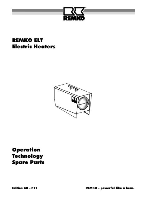
REMKO <strong>ELT</strong><br />
Electric Heaters<br />
Operation<br />
Technology<br />
Spare Parts<br />
Edition <strong>GB</strong> – <strong>P11</strong><br />
REMKO - powerful like a bear.
Operating instructions<br />
Make sure to read these instructions carefully before starting/using the unit!<br />
Our guarantee will become void when the unit supplied by us is used and<br />
Contents Page<br />
Safety Instructions 4<br />
Description of the unit 4<br />
Starting 4<br />
Unit shut down 5<br />
Maintenance 5<br />
Troubleshooting 6<br />
Service and guarantee 6<br />
Technical data 6<br />
� Always<br />
installed for inadequate purposes, or maintained incorrectly, etc.,<br />
or if it is changed without our prior consent.<br />
Subject to alterations!<br />
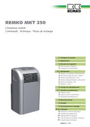
Mobile<br />
Electric Heaters<br />
Contents Page<br />
Exploded view <strong>ELT</strong> 3-2 7<br />
Spare part list <strong>ELT</strong> 3-2 7<br />
Exploded view <strong>ELT</strong> 10-6 8<br />
Spare part list <strong>ELT</strong> 10-6 8<br />
Exploded view <strong>ELT</strong> <strong>18</strong>-9 9<br />
Spare part list <strong>ELT</strong> <strong>18</strong>-9 9<br />
Wiring diagram 10<br />
Maintenance log 11<br />
keep these operating instructions near or on the unit! �<br />
3
Safety Instructions<br />
REMKO electric heaters will provide you with high utility<br />
and long life thanks to our extensive material, function<br />
and quality controls. Dangers may arise nevertheless if<br />
the unit is used by persons not familiar with its operation<br />
or if the unit is not used for its intended purpose.<br />
�<br />
4<br />
The persons charged with the operation of the units<br />
have to check these before starting work as to visible<br />
defects of the operation and safety devices, as well as<br />
to make sure that no protective devices are missing.<br />
In the case of faults the supervisor is to be informed.<br />
In the case of faults which endanger the safe operation<br />
of the units, the units are to be stopped!<br />
During the operation of the units the applicable local<br />
regulations are to be observed and the relevant<br />
safety measures to be taken.<br />
Make sure that the prescribed safety distances from<br />
combustible objects are observed!<br />
A free air suction and air discharge must be ensured.<br />
The blow off opening of the unit may not be narrowed<br />
or equipped with hoses or conduits.<br />
Never place foreign objects into the unit.<br />
Do not cover the units during operation.<br />
The units may not be operated near bath tubs,<br />
showers, swimming pools, etc.<br />
The units may not be operated directly beneath a wall<br />
socket.<br />
The units may not be exposed to direct water jets.<br />
Make sure that no water penetrates inside the units.<br />
The units may not be operated in rooms which are<br />
endangered by explosions.<br />
Protect all electric cables outside the units from<br />
damage (e.g. caused by animals).<br />
Connecting cable extensions may be laid exclusively<br />
by authorised electricians based on the<br />
unit capacity, cable length and taking the local<br />
terms of use into account.<br />
Description of the Unit<br />
The units are operating with electric energy and are<br />
suitable for a fully automatic, all-purpose and simple application.<br />
The units are equipped with capsuled electrical heating<br />
elements, noiseless maintenance-free axial fans, safety<br />
and after-cooling thermostat, thermostat socket and<br />
connecting cable with plug.<br />
The units are in accordance with the basic safety and<br />
health requirements of the relevant EC – regulation.<br />
The units are handled simply and are safe in operation.<br />
Application<br />
Drying of new buildings, spot heating of working<br />
places outside or in fire-proof halls and production<br />
places.<br />
Permanent or temporary heating of rooms.<br />
Defrosting of machines vehicles and fire-proof storing<br />
goods with keeping the prescribed distance of<br />
safety.<br />
Working of the unit<br />
All units can be used for heating or ventilation by setting<br />
the equivalent mode on the operating switch.<br />
The unit <strong>ELT</strong> 3-2 has got exclusively on heating stage<br />
and has a 2 step operating switch.<br />
The units <strong>ELT</strong> 10-6 and <strong>ELT</strong> <strong>18</strong>-9 has got three heating<br />
stages.<br />
The units can be operated with a room thermostat<br />
(accessories) which is ready to be plugged in, to ensure<br />
a constant room temperature. When the pre-selected<br />
temperature has been reached, the thermostat stops<br />
the heating operation to restart it when the temperature<br />
has fallen below the set value.<br />
When the units have been switched off by the operating<br />
switch or the room thermostat, the supply air fan continues<br />
running for a certain time to cool down the heat exchanger,<br />
and then it stops automatically.<br />
� The electric connection of the units is to be carried<br />
out via a special supply point with fault current<br />
safety switch.<br />
Starting<br />
A well trained person is to be charged with the operation<br />
and control of the units.<br />
1. Check the main voltage is in accordance with the<br />
unit voltage.<br />
<strong>ELT</strong> 3-2 230V/1~<br />
<strong>ELT</strong> 10-6 and <strong>ELT</strong> <strong>18</strong>-9 400V/3~<br />
2. Put operating switch into<br />
position "0".<br />
3. Connect the unit-plug to an adequate<br />
mains socket..<br />
<strong>ELT</strong> 3-2 <strong>ELT</strong> 10-6<br />
<strong>ELT</strong> <strong>18</strong>-9
Switch settings<br />
Operating switch<br />
<strong>ELT</strong> 3-2<br />
Operating switch<br />
<strong>ELT</strong> 10-6<br />
<strong>ELT</strong> <strong>18</strong>-9<br />
Ventilation<br />
In this position only the supply air fan runs. The thermostatic<br />
regulation and the heating operation is not possible.<br />
1. Put the operating switch into the necessary position.<br />
Heating without room thermostat<br />
The unit runs under continuous duty.<br />
1. Connect the supplied bridge<br />
circuit plug 2 to the thermostat<br />
socket 1 of the unit.<br />
2. Put the operating switch into the<br />
desired position.<br />
Heating with room thermostat<br />
1. Remove the bridge circuit plug 2.<br />
2. Connect thermostat plug 3 of the<br />
room thermostat (accessories) to<br />
the thermostat socket 1.<br />
3. Put room thermostat 4 in a suitable<br />
place.<br />
The thermostat sensor may not be<br />
exposed directly to the hot air current<br />
and not fixed directly on a cold<br />
surface.<br />
4. Pre-select desired room temperature<br />
on the room thermostat.<br />
5. Put the operating switch into the desired<br />
position.<br />
heating<br />
The unit runs fully automatically and is dependent on<br />
set temperatures.<br />
off<br />
ventilate<br />
off<br />
ventilate<br />
1. stage heating<br />
2. stage heating<br />
3. stage heating<br />
For optimum unit operation, the device should not<br />
� be operated at an ambient temperature above 25 °C.<br />
2<br />
3<br />
4<br />
1<br />
1<br />
Unit Shut Down<br />
1. Put operating switch into<br />
position “0” (OFF).<br />
Attention, important hints to the after-cooling phase.<br />
The air supply fan continues running to cool down the<br />
unit and then stops later.<br />
Fan can start several times before final switching off.<br />
�<br />
Maintenance<br />
<strong>ELT</strong> 3-2 <strong>ELT</strong> 10-6<br />
<strong>ELT</strong> <strong>18</strong>-9<br />
Regular maintenance and the observation of some basic<br />
principles is important to ensure a long service life<br />
and a trouble-free operation of the unit.<br />
�<br />
Please pay attention to the following points:<br />
�<br />
Never interrupt (except in emergency situations)<br />
the connection to the mains before the end of the<br />
whole after-cooling phase.<br />
Our guarantee does not cover damages caused<br />
to the unit by overheating.<br />
Prior to starting any work make sure to pull the<br />
mains plug out of the mains socket!<br />
The unit is to be maintained and cleaned in regular<br />
intervals.<br />
The unit is to be kept free from dust and other deposits<br />
and is to be cleaned only with a dry or humid<br />
cloth.<br />
Do not use water jet.<br />
Do not use any aggressive cleaning agents or those<br />
which are harmful or environmentally unfriendly.<br />
Do not use cleaning agents which contain solvents.<br />
Only use suitable cleaning agents to remove extreme<br />
dirt.<br />
Check safety devices regularly.<br />
Check protective suction and blower grids regularly<br />
and clean, when necessary.<br />
Do not damage the sensor and capillary tube of the<br />
thermostat when the protective blower grid is installed<br />
or removed.<br />
According to the terms of use the units are to be<br />
checked as to their perfect operation by an expert<br />
when necessary, but at least once a year.<br />
Please carry out an electrical safety test after having<br />
finished service on the unit.<br />
5
Troubleshooting<br />
�<br />
Unit (fan) does not start:<br />
1. Check main fuse<br />
2. Check connecting cable with plug<br />
3. Check operating switch<br />
4. Check slight drifting of fan (motor)<br />
Unit does not heat<br />
1. Check operating switch<br />
2. Check auxiliary relay / contactor (<strong>ELT</strong> 10-6 / <strong>ELT</strong> <strong>18</strong>-9).<br />
3. Check function of temperature limiter resp. check<br />
capillary tubing (if damaged)<br />
4. Check if thermostat plug resp. bridge circuit plug is<br />
coupled<br />
5. Check thermostat-operation: thermostat must be set<br />
higher than the room temperature<br />
Should the unit still not be working despite these checks,<br />
please contact an authorised service centre.<br />
Technical Data<br />
Series <strong>ELT</strong> 3-2 <strong>ELT</strong> 10-6 <strong>ELT</strong> <strong>18</strong>-9<br />
Nominal heat output kW 3,2 10,5 <strong>18</strong><br />
Switchable heat output kW 1 x 3,2 3 x 3,5 3 x 6<br />
Air output m³/h 350 750 1000<br />
Electrical connection V 230/1~ 400/3~ 400/3~<br />
Frequency Hz 50 50 50<br />
Rated current A 13,9 14,9 27,5<br />
Power consumption max. kW 3,25 10,65 <strong>18</strong>,2<br />
Fuse protection (required) A (inert) 16 16 32<br />
Sound pressure level LpA 1m 1) dB (A) 46 53 57<br />
Dimensions Length mm 400 675 740<br />
6<br />
Prior to starting any work make sure to pull the<br />
mains plug out of the mains socket!<br />
Setting and maintenance is to be carried out<br />
only by authorised experts!<br />
Width mm 200 300 335<br />
Height mm 335 455 500<br />
Weight kg 6,8 20,0 27,4<br />
1) noise measuring DIN 45635 - 01 - KL 3<br />
Service and Guarantee<br />
Any claims under guarantee regarding materials can be<br />
accepted only when the orderer or his customer has<br />
filled in completely the “guarantee certificate” which is<br />
enclosed with every REMKO-heater and has returned it<br />
to REMKO GmbH & Co. KG in due time after the unit’s<br />
sale and commissioning.<br />
The units are factory tested on faultless function. If any<br />
failure occurs though which cannot be eliminated by the<br />
operating person, please contact your dealer or contact<br />
person.<br />
�<br />
An operation/use other than that indicated in these<br />
instructions is prohibited!<br />
In the case of non-observation we will not be held<br />
responsible and our guarantee will become void.<br />
Correct usage<br />
The units are to be used only for heating and ventilation<br />
purpose in industrial or commercial application because<br />
of their construction and equipment.<br />
If specification of the manufacturer or legal regulations,<br />
are not followed or if unauthorised changes are made<br />
on the unit, the manufacturer is not liable for resulting<br />
damages.
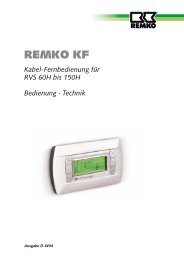
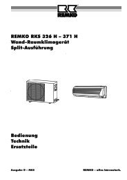
Exploded View <strong>ELT</strong> 3-2<br />
17<br />
<strong>18</strong><br />
16<br />
15<br />
14<br />
19 20<br />
13<br />
12<br />
11<br />
10<br />
Spare Part List <strong>ELT</strong> 3-2<br />
21<br />
23<br />
24<br />
No. Description Ref.-No.<br />
1 transport handle 1101142<br />
2 outside casing 1103905<br />
3 recool thermostat 1104065<br />
4 temperature limiter 1101161<br />
5 inside casing 1103907<br />
6 heating element 1103908<br />
7 heating element 1103909<br />
8 front panel 1103910<br />
9 discharge protection grille 1103803<br />
10 base plate 1103911<br />
11 fan blade 1103902<br />
12 clutch plate 1103912<br />
13 fan motor 1103820<br />
14 rear panel 1103913<br />
15 connecting cable with plug 1103901<br />
16 traction relief 1101267<br />
17 bridge circuit plug 1101019<br />
<strong>18</strong> thermostat socket, cpl. 11010<strong>18</strong><br />
19 operating switch, cpl. 1101<strong>18</strong>8<br />
20 contactor 1108038<br />
21 terminal strip, 6 x 1101366<br />
23 angle support 1101067<br />
24 protection socket, small 1101304<br />
not shown thermostat plug 1101020<br />
3<br />
09/03<br />
We reserve the right to make modifications in dimensions and construction in the interests of technical progress.<br />
1<br />
4<br />
2<br />
5 6<br />
7<br />
8<br />
9<br />
7
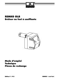
Exploded View <strong>ELT</strong> 10-6<br />
No. Description Ref.-No.<br />
1 transport handle 1101142<br />
2 outside casing 1107910<br />
3 inside casing 1103951<br />
4 discharge protection grille 1103952<br />
5 front panel 1103953<br />
6 base plate 1107913<br />
7 support bracket 1107914<br />
8 temperature limiter with sensor 1107960<br />
9 protection hose 1107915<br />
10 fan blade 1103950<br />
11 clutch plate B8 ∅ 1103956<br />
12 fan motor 1101254<br />
13 rear panel 1103954<br />
14 traction relief 1107944<br />
15 bridge circuit plug 1101019<br />
16 thermostat socket, cpl. 11010<strong>18</strong><br />
17 operating switch, cpl. 1107993<br />
<strong>18</strong> terminal strip, 5 x 1107952<br />
19 contactor 1101025<br />
20 protection socket 1101304<br />
21 heating element 1103955<br />
22 temperature limiter 1101161<br />
23 recool thermostat 1104065<br />
24 angle support 1101031<br />
not shown connecting cable with plug 1101026<br />
thermostat plug 1101020<br />
We reserve the right to make modifications in dimensions and construction in the interests of technical progress.<br />
8<br />
15 16<br />
14<br />
13<br />
17<br />
9<br />
11<br />
10<br />
<strong>18</strong><br />
24<br />
19<br />
Spare Part List <strong>ELT</strong> 10-6<br />
12<br />
8<br />
20<br />
9<br />
21<br />
22<br />
09/03<br />
1<br />
23<br />
8<br />
3<br />
7 6<br />
5<br />
4<br />
2
<strong>ELT</strong> Exploded <strong>18</strong>-9 View <strong>ELT</strong> <strong>18</strong>-9<br />
<strong>18</strong><br />
17<br />
16<br />
15<br />
19<br />
14 13<br />
20<br />
12 11<br />
21 22<br />
Spare Part List <strong>ELT</strong> <strong>18</strong>-9<br />
No. Description Ref.-No.<br />
1 transport handle 1101142<br />
2 outside casing 1107920<br />
4 cone gasket 1107954<br />
3 inside casing with blow-out cone 1107953<br />
5 discharge protection grille 1101353<br />
6 front panel 1107921<br />
7 base plate 1107950<br />
8 temperature limiter with sensor 1107960<br />
9 support bracket 1107922<br />
10 protection hose 1107915<br />
11 fan blade 1101153<br />
12 clutch plate B8 ∅ 1103956<br />
13 fan motor 1101254<br />
14 rear panel 1107923<br />
15 traction relief 1107961<br />
16 thermostat socket, cpl. 11010<strong>18</strong><br />
17 bridge circuit plug 1101019<br />
<strong>18</strong> air suction grille 1107947<br />
19 protection socket 1101304<br />
20 operating switch, cpl. 1107993<br />
21 contactor 1101021<br />
22 terminal strip, 5 x 1107952<br />
23 temperature limiter 1101161<br />
24 recool thermostat 1104065<br />
25 heating element 1107998<br />
not shown connecting cable with plug 1107962<br />
thermostat plug 1101020<br />
10<br />
8<br />
9<br />
10<br />
25<br />
23<br />
1<br />
24<br />
19<br />
3 4 5<br />
We reserve the right to make modifications in dimensions and construction in the interests of technical progress.<br />
7<br />
8<br />
2<br />
6<br />
9
Wiring Diagram<br />
<strong>ELT</strong> 3-2 <strong>ELT</strong> 10-6<br />
230 V / 1~, N, PE / 50 Hz 400 V / 3~, N, PE / 50 Hz<br />
400 3/N ~ 50Hz<br />
L1 N PE<br />
L1 L2 L3 N PE<br />
HR = contactor KL = terminal strip S = operating switch<br />
HW = heating element M = fanmotor STB = temperature limiter (with sensor)<br />
K1 = contactor 1 NK = recool thermostat TB = temperature limiter<br />
K2 = contactor 2 RT = thermostat socket<br />
<strong>ELT</strong> <strong>18</strong>-9<br />
10<br />
KL<br />
6 5<br />
HW2 HW1<br />
6 5 4 3<br />
400 V / 3~, N, PE / 50 Hz<br />
1 3<br />
2<br />
4<br />
5<br />
6<br />
13<br />
14<br />
KL<br />
A2<br />
A1<br />
4 L1 N PE<br />
K2<br />
2 1<br />
1<br />
RT<br />
S<br />
2 3<br />
HR<br />
a b<br />
13 14<br />
23 24<br />
L1 L2 L3 N PE<br />
L1<br />
2<br />
L2 L3<br />
1 3<br />
4<br />
5<br />
6<br />
N<br />
1 2 3 4 5<br />
13<br />
14<br />
1A<br />
2A<br />
3A<br />
A2<br />
A1<br />
K1<br />
M<br />
4B<br />
5B<br />
6B<br />
M<br />
2 3<br />
RT<br />
TB<br />
NK<br />
C<br />
STB<br />
2<br />
1<br />
We reserve the right to make modifications in dimensions and construction in the interests of technical progress.<br />
KL<br />
L1<br />
1 3<br />
2<br />
NK TB<br />
L2 L3<br />
HW S<br />
1 2 3 4 5<br />
L1<br />
V2<br />
L2<br />
V4<br />
L3<br />
V6<br />
4<br />
5<br />
6<br />
M<br />
H<br />
V1<br />
V3<br />
V5<br />
N<br />
13<br />
14<br />
A2<br />
A1<br />
K1<br />
M<br />
2 3<br />
HW<br />
RT<br />
STB<br />
2<br />
1<br />
NK TB<br />
L1<br />
V2<br />
L2<br />
V4<br />
L3<br />
V6<br />
S<br />
M<br />
H<br />
V1<br />
V3<br />
V5
Maintenance Log<br />
Model: ................................ Model No: ......................................<br />
Clean unit -surface-<br />
Clean unit -interior-<br />
Clean protection grille<br />
Clean fan blade<br />
Check safety facility<br />
Check protection guards<br />
Check unit for damage<br />
Check fastening screws<br />
Test run<br />
Electric safety-inspections<br />
1 2 3 4 5 6 7 8 9 10 11 12 13 14 15 16 17 <strong>18</strong> 19 20<br />
Remarks:.......................................................................................................................................................................<br />
......................................................................................................................................................................................<br />
1. Date:………………. 2. Date: ..................... 3. Date: ..................... 4. Date: ..................... 5. Date:……………….<br />
……………………….. .................................. .................................. .................................. ………………………..<br />
Signature Signature Signature Signature Signature<br />
6. Date:………………. 7. Date: ..................... 8. Date: ..................... 9. Date: ..................... 10. Date:……………..<br />
……………………….. .................................. .................................. .................................. ………………………..<br />
Signature Signature Signature Signature Signature<br />
11. Date:…………….. 12. Date: ................... 13. Date: ................... 14. Date: ................... 15. Date:……………..<br />
……………………….. .................................. .................................. .................................. ………………………..<br />
Signature Signature Signature Signature Signature<br />
16. Date:…………….. 17. Date: ................... <strong>18</strong>. Date: ................... 19. Date: ................... 20. Date:……………..<br />
……………………….. .................................. .................................. .................................. ………………………..<br />
Signature Signature Signature Signature Signature<br />
Setting and maintenance work is to be carried out only by authorised specialists!<br />
11
REMKO GmbH & Co. KG<br />
Klima- und Wärmetechnik<br />
D-32791 Lage • Im Seelenkamp 12<br />
D-32777 Lage • PO Box <strong>18</strong>27<br />
Phone +49 5232 606 - 0<br />
Fax +49 5232 606 260<br />
E-Mail info@remko.de<br />
Internet www.remko.de