Graceful Degradationof Digital Audio Transmission Systems*
Graceful Degradationof Digital Audio Transmission Systems*
Graceful Degradationof Digital Audio Transmission Systems*

You also want an ePaper? Increase the reach of your titles
YUMPU automatically turns print PDFs into web optimized ePapers that Google loves.
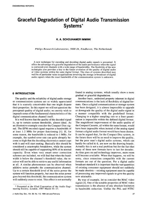
ENGINEERING REPORTS<br />
<strong>Graceful</strong> <strong>Degradationof</strong> <strong>Digital</strong> <strong>Audio</strong> <strong>Transmission</strong><br />
<strong>Systems*</strong><br />
K. A. SCHOUHAMER IMMINK<br />
Philips Research Laboratories, 5600 JA, Eindhoven, The Netherlands<br />
A new technique for encoding and decoding digital audio signals is presented. It<br />
offers the advantage of a graceful degradation of the audio performance when the signal<br />
is conveyed over channels with a wide range of bandwidths. The flexibility of the new<br />
techniques also provides a key to the future evolution of the quality of digital audio<br />
or video systems within the same digital format. The class of systems described may<br />
well be of particular value in applications involving the storage or broadcast of digital<br />
audio signals when the exact bandwidth of the communication system is unknown.<br />
0 INTRODUCTION found in analog systems, which usually show a more<br />
gradual or graceful degradation.<br />
The quality and the reliability of digital audio storage Another basic, undesired property inherent in digital<br />
or communication systems are so widely appreciated communications is the lack of flexibility of digital forthat<br />
it is scarcely conceivable that one might dispute mats. Once a digital communication or storage system<br />
their properties. In this report we will not question the has been designed, it is almost impossible to upgrade<br />
perceptual quality of digital audio; we merely wish to or downgrade the quality of the digital audio signal in<br />
impeach some of the fundamental characteristics of the a manner compatible with the predefined format.<br />
digital communication channel itself. Changing to a higher sampling rate or a finer quanti-<br />
It is well known that the quality of the decoded signal zation is impossible within the defined digital format.<br />
is, up to certain system thresholds, almost ideal. As The magnificent improvement of the audio quality of<br />
an illustrative example consider the Compact Disc sig- the Compact Cassette, all within the same format, would<br />
nal. The EFM encoded signal requires a bandwidth of have been impossible when instead of the analog signal<br />
at least 1.2 MHz for proper functioning [1]. If, for format a digital audio format would have been chosen.<br />
some reason, the bandwidth is reduced to I MHz, for It can be argued that, for the Compact Disc system, in<br />
example, the symbol error rate can quite abruptly be- the future there will be no need to improve the quality,<br />
come so high that the decoding electronics cannot cope but the poor man's digital audio systems, which can<br />
with it and will start muting. Basically this should be hardly be called hi-fi, are now on the drawing boards.<br />
considered a catastrophic breakdown, while the system Actually this is not a real problem but for the fact that<br />
should still be capable of supporting 80% of its normal many of these new formats have to last for decades.<br />
capacity. Even when very smart error correction As time goes on and technology improves, more room<br />
schemes are included, we will find that when the band- will become available. When that happens, we will be<br />
width is below the channel's threshold value, the re- sorry, since extensions compatible with the current<br />
ceiver will not be able to retrieve any useful information formats are out of the question. For a digital audio<br />
at all. A similar phenomenon can be observed when broadcast standard it is important that the vast quantities<br />
additive noise perturbs the communication channel, of existing consumer equipment should not suddenly<br />
Up to a certain threshold level of the noise power the be made obsolete--existing equipment must be capable<br />
system will function properly, but once the noise power of processing any improved signals to give the quality<br />
goes beyond this threshold, the communication system now attainable.<br />
will suddenly cease to exist. This effect is not normally By way of example, let us consider the MAC video<br />
signal [2]. One of the notable properties of MAC video<br />
* Presented at the 82nd Convention of the <strong>Audio</strong> Engi- transmission is the absence of any absolute limitation<br />
neering Society, London, 1987 March 10-13. in bandwidth reduction. Unlike the PAL and NTSC<br />
J,<strong>Audio</strong>Eng.Soc.,Vol.36,No.1/2,1988January/February 27
IMMINK ENGINEERING REPORTS<br />
video signals, one can freely convey the MAC video and detection technique. To focus our thoughts, let us<br />
signal over transmission systems covering a wide range concentrate, for example, on a magnetic or optical reof<br />
bandwidths with the corresponding quality of the corder. It is well known that some parts of the available<br />
received video signal. This property is lost as soon as frequency band of these recording systems are less rethe<br />
MAC video signal is time multiplexed with a digital liable than others. The low-frequency range of a magcomponent<br />
whose rate and coding lead to a minimal netic recorder has insufficient signal-to-noise ratio since<br />
bandwidth greater than, or equal to, that of the MAC the inductive head does not respond to signals of low<br />
video signal. The D2-MAC video format has been cho- frequency. An optical recorder also exhibits an unresen<br />
to accommodate the audio plus video signal in the liable low-frequency response caused by noise which<br />
existing 5-6-MHz cable bandwidth. Once more band- is induced by reflection variations or fingerprints on<br />
width is available, the video quality will improve, but the optical disk. The frequency characteristics in the<br />
unless the digital audio format is changed, the audio high-frequency range of both recorder types are relaquality<br />
will remain the same, thus again fueling the tively unreliable due to defocusing, tape-head loss,<br />
notion that audio is a stepchild of television broad- and so on. We proceed by partitioning the available<br />
casting, bandwidth B into m smaller (virtual) subchannels with<br />
In this report we study a new way of encoding and a bandwidth B/m. We order the subchannels according<br />
decoding digital audio signals which possesses the virtue to their a priori reliability. The subchannel with the<br />
of improved bandwidth adaptability compared with greatest reliability is assigned to the most significant<br />
conventional digital transmission systems. In Sec. 1 bit of the digital audio signal. By modulation of the<br />
we explain in qualitative terms the basic idea of the incoming data on orthogonal time functions, so-called<br />
frequency domain detection technique with a simple carriers (and demodulation in the receiver), it is possible<br />
example. In Sec. 2 we apply the new technique to the to fill the total available frequency range [3]. The signals<br />
transmission of digital audio, generated in this way are multiple valued or even continuous.<br />
Unfortunately many communication or re-<br />
1 BASIC CONCEPT cording channels are "hard-limiting" and accept only<br />
two-level full-T pulses. Examples are optical recording,<br />
Prior to the development of a quantitative model for where only pits or lands can be recorded, and magnetic<br />
the coding and detection technique we consider some recording, which is normally employed in such a way<br />
basics of digital transmission. There are a number of that the resulting magnetic domains are positively or<br />
ways in which digital symbols can be represented by negatively saturated. To overcome this difficulty we<br />
physical parameters. All these involve assigning a range proceed as follows.<br />
of waveforms of a continuously variable physical func- We choose candidate codewords of length n with<br />
tion to represent some digital symbol. Most digital elements from a binary alphabet. The codewords are<br />
systems now in use are binary and synchronous, which also selected in such a way that they divide, according<br />
means that in each symbol time interval or time slot a to a predefined frequency domain criterion, the available<br />
condition such as current or no current, pit or no pit, frequency range of the channel into smaller independent<br />
or positive or negative magnetization is transmitted (or subchannels. The frequency domain criterion will be<br />
stored). (Note that we use the parlance of the corn- based on the (Walsh)-Hadamard transform, which has<br />
munication engineer throughout.) The receiver, under the virtues of simplicity and analytical tractability. A<br />
the control of its clock, properly phased with respect selection of codewords based on other frequency domain<br />
to the incoming data, samples the received signal at criteria is certainly feasible. The major advantage of<br />
the middle of each time slot. It is well known that a Hadamard domain processing compared with Fourier<br />
single pulse transmitted over a bandwidth-limited sys- domain processing is simplified computation, since the<br />
tern is smeared out in time due to convolution with the Hadamard transform requires only addition operations,<br />
channel's impulse response. A sample at the center of whereas the Fourier transform requires complex aritha<br />
symbol interval is a weighted sum of amplitudes of metic.<br />
pulses in several adjacent intervals. This phenomenon We now select the codewords, denoted by x, x i E<br />
is called intersymbol interference (ISI). If the product {- 1, 1}, i = 1 ..... n, to have an odd parity, that is,<br />
of symbol time interval and system bandwidth is re- the number of + 1's is odd. The codeword set is denoted<br />
duced, the intersymbol interference becomes more se- by S. The reason behind this particular choice of codevere.<br />
This effect can become so severe that the receiver, word set will become apparent in the following example.<br />
even in the absence of noise, can no longer distinguish It can readily be verified that 2 n-x codewords satisfy<br />
between the symbol value and the intersymbol inter- this condition. We also define the frequency domain<br />
ference and will start to make errors. The basic idea representation y of x, which results from the n x n<br />
behind the technique to be discussed in the subsequent Hadamard transform,<br />
sections is that the information is not contained in one<br />
time interval but is spread out over a plurality of in- y = H,,x<br />
tervals.<br />
We now leave this typical time-domain approach and where H,,, Hn(i, j) E {- 1, 1}, is the Sylvester-type<br />
turn to a frequency-domain discussion of the coding n × n Hadamard matrix. This selection of the frequency<br />
28 J. <strong>Audio</strong> Eng. Soc., Vol. 36, No. 1/2, 1988 January/February
ENGINEERING REPORTS DIGITAL AUDIO TRANSMISSION SYSTEMS<br />
domain transform restricts the codeword length to rially. The received codeword, denoted by r, generally<br />
powers of 2 (n _ 4). Due to the particular choice of distorted and corrupted with noise, is now Hadamard<br />
the codeword set S we find (this can easily be verified) transformed in the receiver into n = 4 frequency comfor<br />
any x _ S that the elements Yi of the vector y = ponents, denoted by _i, 1 _< i _< n, or<br />
nn2¢ are nonzero.<br />
The basic concept of the new technique is now il- _ = Har . (1)<br />
lustrated by a simple example.<br />
The estimated values of zi, 1
IMMINK ENGINEERING REPORTS<br />
the detection. The same codeword set can be employed r(t + Tc) - r(t + 2To) + r(t + 3Tc)}/2 of subchannels<br />
to transmit information over a bandwidth-limited chan- 2 and 3, respectively. The eye pattern of subchannel 4<br />
channel with the resulting virtue that parts of the trans- is not shown.<br />
mitted information can be retrieved when the bandwidth Figs. 2 and 3 show the effects of the reduction of<br />
is reduced below a certain value. The codeword/source the relative bandwidth to 0.4 and 0.3, respectively.<br />
word assignment is chosen is such a way that the upper (The other parameters are fixed.) Figs. 2(a) and 3(a)<br />
channel does not contain user information. Table 2 correspond to the signal depicted in Fig. l(a). We obshows<br />
the new assignment. Note that the same codeword serve that the higher a particular subchannel is situated<br />
set is employed as that in Table 1. in the frequency band of the channel, the more it is<br />
We leave the foregoing time-discrete analysis and affected by the intersymbol interference caused by the<br />
turn to the time-continuous case. We assume that the relative bandwidth reduction.<br />
channel has a low-pass spectral characteristic with si- Another general point worth mentioning is that of<br />
nusoidal rolloff [5]. The channel waveform, denoted the measure of degradation, the audibility, of the reby<br />
g(t), can be written as constructed signal. How can we compare quantitatively<br />
a channel with a given reliability with another channel<br />
sin 2_rBt cos 213_rBt consisting of a number of subchannels each with a cerg(t)<br />
-<br />
2_rBt 1 - 16132B2tz tain reliability? It is notoriously difficult to specify<br />
quantitatively the degree of annoyance experienced by<br />
where B is the bandwidth of the transmission system a human observer. Dostis [6] arrived at the following<br />
and 13, 0 _< 13_< 1, is the rolloff parameter. The term simple mathematical relation that takes account of the<br />
sinusoidal rolloff becomes clear when we write the effects of both quantization and incorrect decoding of<br />
corresponding frequency characteristic of the channel the received data,<br />
G(f/B),<br />
"1, 0
ENGINEERING REPORTS DIGITAL AUDIOTRANSMISSION SYSTEMS<br />
Fig. 4 shows the SNR of both the new and the con- audio signal with an SNR of 40 dB. As can be seen,<br />
ventional systems as a function of the relative bandwidth the cost of the new system is fairly low; it requires a<br />
BT of the transmission system (no additive noise as- 10% larger bandwidth than the conventional system to<br />
sumed). The relative bandwidth of the two systems has support maximum user capacity. In the next example<br />
been scaled in such a way that they convey, per unit we give some numerical data to exemplify the previous<br />
of time, equal amounts of user information 1/T (bits theory.<br />
per second) at maximum bandwidth. Note that TJT =<br />
3/4. The diagram shows better than words can explain 2.1 Example 2<br />
the sudden loss of quality--the threshold effect--of The data bit rate of a digital audio signal is readily<br />
the conventional system when the transmission band- found. Assume a stereo channel, 15-bit quantization,<br />
width is reduced below a certain critical value. The and a 48-kHz sample frequency. The data bit rate (exdiagram<br />
reveals quite clearly that the new system is cluding error correction, subcode, synchronization, etc.)<br />
partitioned into three subsystems. At a relative band- is 2 × 48 x 15 = 1.440 Mbit/s, or T = 694 ns. From<br />
width BT = 0.2, which is a factor of 2 smaller than Fig. 4 we find that when conventional techniques are<br />
the critical bandwidth of the conventional system, the used, the minimum requirement of the bandwidth of<br />
new system is still capable of supporting a 5-bit digital the transmission channel is 0.42 x 1.44 = 600 kHz.<br />
_2<br />
T-<br />
-2 -1 O -2 -1 0 I 2<br />
TIMEVTO TIME/TC<br />
Ca) Ca)<br />
- - 2 _ -1<br />
TIME/T 0 TIME/T 0<br />
(b) (b)<br />
o _i_'_ _L"_ _),_"-/\-"--_..._ _ "_'_
IMMINK ENGINEERING REPORTS<br />
The diagram clearly reveals that when the channel 2<br />
bandwidthis smallerthan this threshold value, no re- ..l<br />
= il:<br />
ception at all is possible. When the new technique is _ ....... -..."<br />
used, we find that the channel bit rate, that is, the bit _ g / :<br />
rate after the channel encoder, is 4/3 x 1.440 = 1.92 z<br />
Mbit/s. ception bandwidth The is 0.47×1.44--677 is minimum 0.36 x 1.44 bandwidth = 518 kHz. kHz, for When awefull are the15-bit still channel able re- :__ J,.-.i-.:,_..................... _...-i..--.-t- /-I--'l" ] i"J- "...... "?" "<br />
to decode a 10-bit audio signal. When the bandwidth<br />
is further reduced to 0.18 x 1.44 = 260 kHz, we can<br />
o-,<br />
0.1<br />
"<br />
0.2<br />
"<br />
0.3 0.4<br />
RelativeBandwidth8"1"<br />
0.8 O.<br />
retrieve a 5-bit audio signal.<br />
It is possible and indeed preferable in this coding Fig. 4. Signal-to-noise ratio as a function of transmission<br />
bandwidth. Dashed curve--new system; dotted curvescheme<br />
for each of the created subchannels to have a conventional system.<br />
separate error correction and detection control. The<br />
error control mechanism can decide whether one or<br />
more of the subchannels are beyond their operating<br />
conditions and may decide not to use them, whereby it should be noted that this decision can be made entirely<br />
in the receiver. Obviously, a subset of the available<br />
2 !<br />
subchannels can also be used as a tool for design flex-<br />
N<br />
.._____ ibility. For example, we may decide to implement a<br />
t .'_=_3_,._. _:_ r _ decoding of the full set or of part of the set of the<br />
_I_-__-'--_ _ _:__ available subchannels, which leads to a corresponding<br />
me / =-_-.. _.,__--.'_____ ------_._<br />
reduction of the required decoding hardware and of<br />
,.onu ,it, of ae oae a aio sig a, ougwe<br />
-2<br />
-a -1 0<br />
--_<br />
1 2<br />
coined the term "graceful" degradation for the new<br />
technique, it canbe understoodthat the newtechnique<br />
TIME/Tc provides a key to future evolution, that is, upgrading,<br />
(a) of the quality of digital audio systems within the same<br />
2 digitalformat.If currenttechnologyallowsa relative<br />
_-- _ =_ _ _'* bandwidth of B T = 0.2, we can receive a 5-bit digital<br />
i _<br />
z 0<br />
_<br />
_ _<br />
_ _<br />
_<br />
audiosignal.Astimegoeson, technologywillprovide<br />
more bandwidth, which allows the reception of higher<br />
quality audio in a manner compatible with the lowaJ<br />
_ "_--"- - _ _ - _ _ bandwidth system.<br />
-a -1 o i 2 3 CONCLUSIONS<br />
TIME/TC<br />
(b) A new coding and detecion techniquewas presented<br />
which offers the virtues of graceful degradation and<br />
2 _ _ /_ _ _ _ the flexibility to up- or downgrade the quality of the<br />
._,_x,,, _.._.._-_-_.._ _ -- _ transmission system. It has been shown that residual<br />
o _-_ _,e,// _ _ _ _ _ _ intersymbol error probability interference of the least hasand a different most significant effect onsym- the<br />
-I _ _ _ _ _ _ _ _ bolswhenfrequencydomaindetectionof a set of code-<br />
_. -......_e_'- _--,...__ words is employed. The class of systems described<br />
-2 o _ maywellbeof particularvalueinapplicationsinvolving<br />
TIME/TC the storage or transmission of ordered data, such as<br />
digital video or audio, when the receiver or the trans-<br />
(c) mitter has no exact knowledge of the channel bandwidth.<br />
a Theflexibilityofthenewcodingtechniquealsoprovides<br />
_z o1___-..__ _ ___ _ _ akeytothefutureevolutionofthequalityofdigital<br />
audioor videosignalswithinthe samedigitalformat.<br />
a_ __ _ _ _ _ _ .I >
ENGINEERING REPORTS DIGITALAUDIOTRANSMISSION SYSTEMS<br />
tribution," J. IERE, vol. 56, pp. 53-61 (1986). 238 (1983 Apr.).<br />
[3] H. F. Harmuth, <strong>Transmission</strong> of Information by [5] J.G. Proakis, <strong>Digital</strong> Communications (McGraw-<br />
Orthogonal Functions, 2nd ed. (Springer, Berlin and Hill, New York, 1983).<br />
New York, 1972). [6] I. Dostis, "TheEffect of <strong>Digital</strong> Errorson PCM<br />
[4] T. T. Doi, "Channel Codings for <strong>Digital</strong> <strong>Audio</strong> <strong>Transmission</strong> of Compandored Speech," Bell Sys. Tech.<br />
Recordings," J. <strong>Audio</strong> Eng. Soc., vol. 31, pp. 224- J., vol. 44, pp. 2227-2243 (1965).<br />
THE AUTHOR<br />
Kees A. Schouhamer Immink was born in Rotterdam, Dr. Immink is coauthor of a book entitled Principles<br />
The Netherlands, in 1946. He received a B.S. degree of Optical Disc Systems. He was awarded a fellowship<br />
from Rotterdam Polytechnic in 1967 and M.S. and bytheAESin 1985 for "his work in the area of optical<br />
Ph.D. degrees from the Eindhoven University of laser disk and for detailed study on channel codes for<br />
Technology in 1974 and 1985, respectively, all in the Compact Disc." He serves as a member of the Orelectrical<br />
engineering. He joined the Philips Research ganizing Committee of the International Conference<br />
Laboratories, Eindhoven, in 1968, where his work in- on Video, <strong>Audio</strong>, and Data Recording and is on the<br />
volved the signal processing side of optical recording committee of the AES Netherlands Section and the<br />
systems. Since 1986, he has been a member of the Benelux Community on Information and Communimagnetic<br />
recording group at Philips Research. cation Theory. He is a fellow of the IERE.<br />
J. <strong>Audio</strong> Eng. Soc., Vol. 36, No. 1/2, 1988 January/February 33