Installation, Service & Maintenance Manual - Hardy Diesel Generators
Installation, Service & Maintenance Manual - Hardy Diesel Generators
Installation, Service & Maintenance Manual - Hardy Diesel Generators

You also want an ePaper? Increase the reach of your titles
YUMPU automatically turns print PDFs into web optimized ePapers that Google loves.
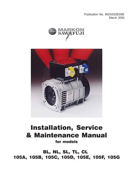
Publication No. M2/0/025ED6E<br />
March 2000<br />
<strong>Installation</strong>, <strong>Service</strong><br />
& <strong>Maintenance</strong> <strong>Manual</strong><br />
for models<br />
BL, NL, SL, TL, CL<br />
105A, 105B, 105C, 105D, 105E, 105F, 105G
SAFETY PRECAUTIONS<br />
Before operating the generating set, read the generating set operation manual and<br />
this generator manual and become familiar with it and the equipment.<br />
SAFE AND EFFICIENT OPERATION CAN ONLY BE ACHIEVED IF THE<br />
EQUIPMENT IS CORRECTLY OPERATED AND MAINTAINED.<br />
Many accidents occur because of failure to follow fundamental rules and<br />
precautions.<br />
ELECTRICAL SHOCK CAN CAUSE SEVERE PERSONAL INJURY OR DEATH.<br />
l Ensure installation meets all applicable safety and local electrical codes. Have<br />
all installations performed by a qualified electrician.<br />
l Do not operate the generator with protective covers, access covers or terminal<br />
box covers removed.<br />
l Disable engine starting circuits before carrying out maintenance.<br />
l Disable closing circuits and/or place warning notices on any circuit breakers<br />
normally used for connection to the mains or other generators, to avoid<br />
accidental closure.<br />
Observe all IMPORTANT, CAUTION, WARNING, and DANGER notices,<br />
defined as:<br />
Important ! Important refers to hazard or unsafe method or practice<br />
which can result in product damage or related equipment<br />
damage.<br />
Caution ! Caution refers to hazard or unsafe method or practice<br />
which can result in product damage or personal injury.<br />
Warning !<br />
Danger !<br />
Warning refers to a hazard or unsafe method or practice<br />
which CAN result in severe personal injury or possible<br />
death.<br />
Danger refers to immediate hazards which WILL result in<br />
severe personal injury or death.<br />
Due to our policy of continuous improvement, details in this manual which were correct at time of printing,<br />
may now be due for amendment. Information included must therefore not be regarded as binding.
FOREWORD<br />
The function of this book is to provide the user of the Markon generator with an<br />
understanding of the principles of operation, the criteria for which the generator<br />
has been designed, and the installation and maintenance procedures.<br />
Each generator has been so designed, constructed, tested and examined as to<br />
ensure that it will be safe and without risk to health when properly used. Machine<br />
outputs etc. are shown on the nameplate attached to the frame.<br />
Specific areas where the lack of care or use of incorrect procedures could lead to<br />
equipment damage and/or personal injury are highlighted, with IMPORTANT,<br />
CAUTION, WARNING and/or DANGER notes, and it is IMPORTANT that the<br />
contents of this book are read and understood before proceeding to fit or use the<br />
generator.<br />
Any persons carrying out operating and maintenance procedures should wear<br />
any appropriate protective clothing and equipment, use the correct tools and<br />
observe any regulations contained in, or made pursuant, to the Health and Safety<br />
at Work Act 1974 or any other relevant statute.<br />
The <strong>Service</strong>, Sales and technical staff of Markon are always ready to assist and<br />
reference to the company for advice is welcomed.<br />
EC DECLARATION OF INCORPORATION<br />
All Markon generators are supplied<br />
with a declaration of incorporation<br />
for the relevant EC legislation,<br />
typically in the form of a label as below.<br />
Under the EC Machinery Directive<br />
section 1.7.4. It is the responsibility<br />
of the generator set builder to<br />
ensure the generator serial and<br />
identity numbers are clearly<br />
displayed in the space provided<br />
inside the back cover of this book.<br />
Markon generators are manufactured to Q.A. procedures<br />
conforming to BS EN ISO 9002.<br />
1<br />
IN ACCORDANCE WITH THE SUPPLY OF MACHINERY (SAFETY) REGULATIONS 1992<br />
AND THE SUPPLY OF MACHINERY (SAFETY) (AMENDMENT) REGULATIONS 1994<br />
IMPLEMENTING THE EC MACHINERY DIRECTIVE 89/392/EEC AS AMENDED BY 91/368/EEC.<br />
THIS STAMFORD A.C GENERATOR WAS<br />
MANUFACTURED BY OR ON BEHALF OF<br />
NEWAGE INTERNATIONAL LTD<br />
BARNACK ROAD STAMFORD LINCOLNSHIRE ENGLAND<br />
THIS COMPONENT MACHINERY MUST NOT BE PUT INTO SERVICE UNTIL THE<br />
MACHINERY INTO WHICH IT IS TO BE INCORPORATED HAS BEEN DECLARED IN<br />
CONFORMITY WITH THE PROVISIONS OF THE SUPPLY OF MACHINERY (SAFETY)<br />
REGULATIONS 1992/MACHINERY DIRECTIVE.<br />
OR AND ON BEHALF OF NEWAGE INTERNATIONAL LIMITED<br />
NAME:<br />
POSITION:<br />
SIGNATURE:<br />
LAWRENCE HAYDOCK<br />
TECHNICAL DIRECTOR<br />
THIS COMPONENT MACHINERY CARRIES THE CE MARK FOR COMPLIANCE WITH THE STATUTORY<br />
REQUIREMENTS FOR THE IMPLEMENTATION OF THE FOLLOWING DIRECTIVES<br />
The EMC Directive 89/336/EEC<br />
WARNING! This Component Machinery shall not be used in the Residential, Commercial and<br />
Light Industrial environment unless it also conforms to the relevant standard<br />
(EN 50081 - 1) REFER TO FACTORY FOR DETAILS<br />
ii) The Low Voltage Directive 73/23/EEC as amended by 93/68/EEC
ELECTROMAGNETIC COMPATIBILITY<br />
Additional Information<br />
European Union<br />
Council Directive 89/336/EEC<br />
For installations within the European Union, electrical products must meet the<br />
requirements of the above directive, and Markon ac generators are supplied on the<br />
basis that:<br />
l They are to be used for power-generation or related function.<br />
l They are to be applied in one of the following environments:<br />
Portable (open construction - temporary site supply)<br />
Portable (enclosed - temporary site supply)<br />
Containerised (temporary or permanent site supply)<br />
Ship-borne below decks (marine auxiliary power)<br />
Commercial vehicle (road transport / refrigeration etc)<br />
Rail transport (auxiliary power)<br />
Industrial vehicle (earthmoving, cranes etc)<br />
Fixed installation (industrial - factory / process plant)<br />
Fixed installation (residential, commercial and light industrial - home / office /<br />
health)<br />
Energy management (Combined heat and power and/or peak lopping)<br />
Alternative energy schemes<br />
l The standard generators are designed to meet the ‘industrial’ emissions and<br />
immunity standards. Where the generating set is required to meet the<br />
residential, commercial and light industrial emissions and immunity standards<br />
then reference should be made to the factory.<br />
l The installation earthing scheme involves connection of the generator frame<br />
to the site protective earth conductor using a minimum practical lead length.<br />
l <strong>Maintenance</strong> and servicing with anything other than factory supplied or<br />
authorised parts will invalidate any Newage liability for EMC compliance.<br />
2
CONTENTS<br />
SECTION 1 INTRODUCTION 5<br />
1.1 BL105 Generator 5<br />
1.2 NL105 Generator 6<br />
1.3 SL105 Generator 7<br />
1.4 TL105 Generator 8<br />
1.5 CL105 Generator 9<br />
SECTION 2 APPLICATION 10<br />
2.1 Standards 10<br />
2.2 Airflow 10<br />
2.3 Direction Of Rotation 10<br />
2.4 Drive Arrangement 10<br />
2.4.1 Road Vehicle <strong>Generators</strong> 10<br />
2.5 Bearings 11<br />
2.5.1 Road Vehicle <strong>Generators</strong> 11<br />
2.6 Earthing 11<br />
2.7 Loading 11<br />
SECTION 3 INSTALLATION 12<br />
3.1 Safety Warnings 12<br />
3.2 Inspection 12<br />
3.3 Coupling to Engine 12<br />
3.4 Electrical Connections 12<br />
3.5 Voltage Selection 14<br />
3.6 Voltage Adjustment For The SL105 - AVR MD1C 15<br />
SECTION 4 SERVICE & MAINTENANCE 17<br />
4.1 General 17<br />
4.2 Insulation Resistance Check 18<br />
4.3 Fault Finding 18<br />
4.4 Residual Voltage/Field Flashing 24<br />
4.4.1 Linear Reactor Check 25<br />
4.4.2 Current Transformer Check 25<br />
4.5 Resistance Charts 26<br />
SECTION 5 ASSEMBLY/DISMANTLING PROCEDURE 28<br />
5.1 Assembling Generator To Engine 28<br />
5.2 Dismantling Stator Frame Assembly 29<br />
5.3 Withdrawing Rotor From Engine 29<br />
5.4 Removal/Replacement Of Capacitor - BL Models 29<br />
3
CONTENTS<br />
5.5 Removal/Replacement Of Diode<br />
Varistor Assembly - BL Models 29<br />
5.6 Removal/Replacement Of AVR - SL Models 30<br />
5.7 Removal/Replacement Of AVR<br />
- TL Models 30<br />
5.8 Removal/Replacement Of Diode Bridge<br />
- SL and NL Models 30<br />
5.9 Removal/Replacement Of Choke<br />
- SL and NL Models 31<br />
5.10 Removal/Replacement Of Radio Interference<br />
Suppressor (RIS) -SL and TL Models 31<br />
5.11 Removal/Replacement Of Bearing 31<br />
5.12 Removal/Replacement Of Brushes/Brush Calliper<br />
Assembly - CL Models 32<br />
5.13 Removal/Replacement Of Brushes/Brushbox<br />
Assembly - SL, TL, & NL Models 32<br />
5.14 Torque Settings 32<br />
SECTION 6 SPARES AND AFTER SALES SERVICE 33<br />
6.1 Recommended Spares 33<br />
6.2 After Sales <strong>Service</strong> 34<br />
BL105 Parts Identification - Single Bearing 35<br />
Typical BL105 Generator - Single Bearing 36<br />
NL105 Parts Identification 37<br />
Typical NL105 Generator 38<br />
SL105 Parts Identification 39<br />
Typical SL105 Generator 40<br />
BL105 Parts Identification - Two Bearing 41<br />
Typical BL105 Generator - Two Bearing 42<br />
TL105 Parts Identification 43<br />
Typical TL105 Generator 44<br />
CL105 Parts Identification 45<br />
Typical CL105 Generator 46<br />
Warranty Details Inside Backcover<br />
4
SECTION 1<br />
INTRODUCTION<br />
Models covered by this manual are designated as follows:-<br />
BL105A NL105E SL105A TL105E CL105G<br />
BL105B NL105F SL105B TL105F<br />
BL105C NL105G SL105C TL105G<br />
BL105D SL105D<br />
BL105E SL105E<br />
BL105F SL105F<br />
BL105G SL105G<br />
1.1 BL105 GENERATOR<br />
The BL105 is a self exciting brushless generator, designed to operate with single<br />
phase loads at or near a power factor of 1.0. The principle of operation is<br />
schematically represented in the diagram below. The auxiliary winding, in<br />
conjunction with the excitation capacitor, provides excitation by inducing current in<br />
the rotor (field) windings which is rectified to produce a direct current field. The<br />
main stator winding is designed for series/parallel connection to give a dual voltage<br />
output and no voltage adjustment is possible.<br />
Main Stator Windings<br />
Rotor Windings<br />
Auxiliary Windings<br />
5<br />
Excitation<br />
Capacitor
1.2 NL105 GENERATOR<br />
The NL 105 generator is of self-exciting rotating field design.<br />
The principle of operation is schematically represented in the diagram below. The<br />
auxiliary winding provides excitation power through a choke and rectifier into the<br />
rotating field via sliprings.<br />
The main stator winding is designed for series/parallel connection to give a dual<br />
voltage output primarily designed for unity power factor loads.<br />
Rotor<br />
Windings<br />
Some NL 105 generators are supplied with a d.c. auxiliary output winding and are<br />
schematically represented in the diagram below.<br />
Auxilary<br />
Winding<br />
Main Stator Windings<br />
Rectifier<br />
Rectifier<br />
6<br />
Choke<br />
Auxiliary<br />
Windings<br />
+ ve<br />
- ve<br />
dc
1.3 SL105 GENERATOR<br />
The SL105 generator is of self-exciting, automatic voltage regulator (AVR)<br />
controlled, rotating field design. It is designed to operate with close regulation when<br />
supplying single phase loads. Primarily designed for loads at or near unity power<br />
factor, it has a capability of operation at 0.8 power factor.<br />
The principle of operation is schematically represented in the diagram below. The<br />
auxiliary winding provides excitation power through a choke and rectifier into the<br />
rotating field via sliprings.<br />
The AVR diverts excess excitation at low loads to maintain the main stator winding<br />
output voltage within close limits.<br />
The main stator winding is designed for series/parallel connection to give a dual<br />
voltage output with voltage adjustment.<br />
Rotor<br />
Windings<br />
Main Stator Windings<br />
AVR<br />
Rectifier<br />
The SL105 generator may be supplied without a divertor AVR for specific<br />
applications. For these generators the instructions given in this manual for the<br />
SL105 generator apply, but references to the AVR or its control should be ignored.<br />
7<br />
Choke<br />
Auxiliary<br />
Windings
1.4 TL105 GENERATOR<br />
The TL105 is a self-exciting, automatic voltage regulator (AVR) controlled rotating<br />
field three phase generator. It is designed to operate with close voltage regulation<br />
when supplying balanced and unbalanced loads at power factors between 0.8<br />
and 1.0.<br />
The principle of operation is schematically represented in the block diagram<br />
below.<br />
The aux stator winding provides excitation power through the AVR which controls<br />
the level of excitation passed via the sliprings into the field winding (rotor).<br />
The AVR senses the voltage output of the main stator winding and controls the<br />
excitation at varying loads to maintain the main stator winding output voltage<br />
within close limits.<br />
AVR<br />
Brushes/Sliprings<br />
Rotor Windings<br />
Note: AVR tapping point varies depending upon generator output voltage, the AVR<br />
input voltage must be in the range of 100 - 120v.<br />
8<br />
Stator Windings<br />
AUX<br />
N<br />
W<br />
V<br />
U
1.5 CL105 GENERATOR<br />
The CL105 is a self-exciting three phase generator having current compounded<br />
excitation control. It is specifically designed for use in vehicle refrigeration<br />
equipment and is capable of operation over a wide speed range, i.e. 1800 to 3600<br />
r.p.m., delivering an output voltage of 250 to 500 volts at frequencies of 30 to 60 Hz<br />
respectively.<br />
The excitation control, which may be generator mounted or remote, consists of a<br />
linear reactor (LR) providing the no-load excitation component, and a current<br />
transformer (CT) providing the increased excitation required when the generator is<br />
loaded.<br />
It is the frequency sensitive nature of the LR and CT that enables virtually<br />
proportional control of output voltage with respect to speed (or Hz).<br />
The principle of operation is schematically represented below.<br />
The elements of excitation power derived from the LR and CT are vectorially<br />
summed, rectified and fed via sliprings into the main field (rotor) winding, such that<br />
the generator output voltage is maintained within limits with varying load.<br />
9
2.1 STANDARDS<br />
SECTION 2<br />
APPLICATION<br />
The generator has been designed to comply with the requirements of most<br />
International Standards and is suitable for operation in an ambient temperature of<br />
40°C maximum.<br />
2.2 AIRFLOW<br />
The generator should be positioned so that the cooling air may enter and leave the<br />
machine without restriction. Inadequate ventilation to the generator will lead to<br />
serious overheating and subsequent damage to windings.<br />
2.3 DIRECTION OF ROTATION<br />
The generator is suitable for either direction of rotation.<br />
2.4 DRIVE ARRANGEMENT<br />
All models are designed to suit engines having a drive shaft/crankcase mounting<br />
arrangement to SAE J609a Flange A Extension 5 (3/4" Taper) or Flange B<br />
Extension 6 (7/8" Taper) depending upon output kW.<br />
Two bearing drive arrangements are available with a 22mm diameter 45.5mm long<br />
shaft extension.<br />
The minimum pulley pitch diameter to be used for belt driven application is 118mm<br />
with a maximum side loading of 700N, to achieve full output and a reasonable<br />
bearing life. If smaller pulleys are required refer to factory for maximum side load<br />
and bearing life. Where single bearing to two bearing conversion parts have been<br />
supplied fitting instructions are provided with the kit.<br />
2.4.1 ROAD VEHICLE GENERATORS<br />
A special two bearing arrangement is used for this application to accomodate high<br />
bearing loadings and vibration. The standard 22mm diameter, 45.5mm long shaft<br />
extension is used.<br />
The minimum pulley pitch diameter to be used is 118mm with a maximum side<br />
loading of 1000N.<br />
10
2.5 BEARINGS<br />
The bearing is preloaded and sealed for life and should require no further attention.<br />
Care must be taken to ensure that the anti-creep circlip is correctly located in the<br />
groove before mating with the end bell bearing housing, i.e. the bump on the circlip<br />
is in the deepest part of the groove.<br />
On two bearing machines the drive end bearing is a standard ball bearing sealed<br />
for life.<br />
2.5.1 ROAD VEHICLE GENERATORS<br />
These generators are fitted with larger bearings than standard. The drive end<br />
bearing is clamped in the drive end bracket and the non drive end bearing is fitted<br />
in a steel housing with an 'O' ring to prevent turning.<br />
2.6 EARTHING<br />
The generator is manufactured and delivered with the stator windings completely<br />
isolated from the frame; a suitable earth terminal is provided on the bearing support<br />
for bonding to the generating set frame.<br />
Access to the earth terminal is gained by removal of the end cover.<br />
2.7 LOADING<br />
The generators are suitable for supplying, continuously, most types of load with a<br />
total load current not exceeding the current quoted on the nameplate. Two points<br />
should be noted however:<br />
1. Engine Power.<br />
The generator set output may be limited by the horsepower rating of the<br />
engine. As a guide the engine has to supply approximately two horsepower<br />
for each 1000 watts (1kW) of electrical load. Refer to factory for specific<br />
generator efficiency.<br />
2. Electric Motor Loads.<br />
The current taken by a motor on full load is shown on its nameplate, but it<br />
will be several times this value at the instant of starting even when there is<br />
no load on the motor. The actual value depends on the type of motor and<br />
the starting current should be checked before attempting to decide the size<br />
of generator required.<br />
When starting a motor the total current including any other load should not exceed<br />
twice the full-load current of the generator on BL105 models. The total current<br />
should not exceed 1.5 times the full-load current on SL105 and TL105 models.<br />
The total current during motor starting on CL models should not exceed 3 times the<br />
generator full load current. In this case the total kW during the starting period may<br />
exceed the generator rated kW and it is essential to ensure that the selected<br />
engine is capable of providing the kW required. As a guide the engine rating<br />
should be approximately 3 HP for each 1000 watts (1kW) of the starting kW. Refer<br />
to the factory for specific applications.<br />
11
3.1 SAFETY WARNINGS<br />
The generator is supplied as a component part for<br />
installation on a generating set and it is the<br />
responsibility of the generating set builder to fit the<br />
safety warning label, illustrated right, which is<br />
supplied packaged with this manual. The label<br />
should be attached to the generator in a position<br />
where it is clearly visible on the generating set.<br />
3.2 INSPECTION<br />
When the equipment is received all details,<br />
especially the Serial Number of the generator,<br />
should be checked against the Advice Note.<br />
Carefully remove all dust and packing materials.<br />
In the event of any part being damaged or<br />
missing, this should be reported at once to the<br />
manufacturer and the transport company.<br />
Always quote the Serial Number<br />
on correspondence with the manufacturer.<br />
When nameplates are supplied packaged with the machine, but not fitted, it is the<br />
responsibility of the installer to fit the nameplate to the generator.<br />
3.3 COUPLING TO ENGINE<br />
Refer to Assembly/Dismantling Procedure. SECTION 5.<br />
3.4 ELECTRICAL CONNECTIONS<br />
SECTION 3<br />
INSTALLATION<br />
The generators are supplied from the factory with flying leads from the main stator<br />
windings. The BL105, NL105 & SL105 may be permanently connected or switched<br />
in the generator set outlet box to obtain the required output voltage(s). The<br />
installer must provide necessary overload protection. The windings are not bonded<br />
to the machine frame and it is the responsibility of the installer to provide suitable<br />
bonding to earth. Reference should be made to relevant site or safety regulations.<br />
Note that the point of earthing the stator winding is at the discretion of the installer.<br />
Normally a 230 volt 2 wire output will be earthed at one end giving a maximum of<br />
230 volts to earth (0r 115 volts in parallel mode).<br />
12
A 110 volt 2 wire output will normally be earthed at the centre tap (series<br />
connection point) giving a maximum of 55 volts to earth.<br />
The standard TL105 arrangement provides six line output leads for connection in<br />
Star or Delta configuration.<br />
The CL105 generator may be supplied with flying leads from the main stator<br />
windings terminated in a socket and separate excitation control components, or as<br />
a complete generator package with control components located in a generator<br />
mounted box with output terminals. The neutral of the windings on the CL<br />
generator is connected to the frame earth terminal.<br />
When separate excitation components are supplied, interconnection between them<br />
is made with multipin sockets and plugs. The installer must provide mounting for<br />
the components and ensure adequate ventilation. Refer to the factory if in doubt.<br />
Reference should be made to relevant site or safety regulations.<br />
13
3.5 VOLTAGE SELECTION<br />
1. Dual Voltage Output<br />
The main stator windings are in two sections which may be connected in series<br />
or parallel to give a choice of output voltage. For example, series connection<br />
gives 230V, parallel connection gives 115V.<br />
This is illustrated below. Each winding section is capable of carrying the same<br />
current I. When the windings are connected in series the maximum load current is<br />
I, but when the windings are connected in parallel the maximum current is 2 X I.<br />
Example:<br />
A 2.5kVA generator when connected in series for 230V operation has a capacity of<br />
10.9A; when connected in parallel for 115V it has a capacity of 21.7A.<br />
Parallel Connection<br />
Red<br />
White<br />
Brown<br />
Blue<br />
U1<br />
U2<br />
U5<br />
U6<br />
115V<br />
Output<br />
4 Wire<br />
Red<br />
White<br />
Brown<br />
Blue<br />
2. 110V CTE Output (BL105 range only).<br />
U1<br />
U2<br />
U5<br />
U6<br />
Series Connection<br />
Red<br />
White<br />
Brown<br />
Blue<br />
U1<br />
U2<br />
U5<br />
U6<br />
230V<br />
Output<br />
The main stator windings are in two sections which should be connected in<br />
series to give 110V output, with the centre tap taken from the series connection<br />
point.<br />
14
3.6 VOLTAGE ADJUSTMENT FOR THE SL105 - AVR MD1C<br />
The voltage is set during manufacture to give the mid-voltage of the range of<br />
voltages shown on the nameplate, ie: a generator whose nameplate is marked<br />
220-240/110-120V will be set to give 230 volts with the output windings connected<br />
in series and 115 volts when connected in parallel.<br />
The voltage may be reset to any value within the nameplate range.<br />
To RAISE the voltage turn the volts adjust potentiometer VR1<br />
CLOCKWISE and to LOWER the voltage turn the potentiometer<br />
ANTI-CLOCKWISE.<br />
The volts adjust potentiometer is the one at the bottom of the board.<br />
STABILITY<br />
This control should not normally require adjustment having been set during<br />
manufacture, but should the output voltage fluctuate with a steady load connected,<br />
this may be improved by turning the potentiometer anti-clockwise which will<br />
increase the damping effect.<br />
Note<br />
1. Do not use undue force when turning the potentiometers - they can be<br />
damaged by attempting to adjust beyond the internal stops.<br />
2. When making either adjustment the speed must be correct.<br />
TL Models<br />
TL generators have a voltage range of approximately 5%, e.g. 380 - 415 volts.<br />
Voltage adjustment is effected by adjustment of the ‘SET VOLTS’ control<br />
potentiometer located on the AVR. Access to the AVR is gained by removal of the<br />
cover of the black, side mounted box.<br />
Danger !<br />
Removal of the air intake cover allows access to ‘LIVE’ parts.<br />
Only persons qualified to carry out electrical servicing should<br />
carry out adjustments.<br />
15
TL generators may be supplied with a 12 lead winding suitable for series/parallel<br />
connection.<br />
The installer must provide suitable terminations or switching arrangements to<br />
provide a safe reconnection means.<br />
CL Models<br />
CL generators are factory set and require no adjustment.<br />
Should the voltage be incorrect at no-load, switch load (at least 50%) on and off<br />
and recheck voltage. (Voltage will normally rise after application of load.) If voltage<br />
is still incorrect adjustment can be made as follows:-<br />
First check that the speed is correct (normally 3150 rpm no-load and 3000 rpm on<br />
load for 50Hz generators or 3790 rpm and 3600 rpm respectively for 60Hz<br />
generators).<br />
The linear reactor controls the no-load voltage by adjustment of its airgap.<br />
Increasing gap increases voltage; decreasing gap decreases voltage. To adjust<br />
the airgap length, slacken the clamping bolts across the top of the reactor and<br />
adjust the thickness of packing in the ‘airgap’. Packing must be non magnetic<br />
material.<br />
After each adjustment, switch load (at least 50%) on and off and recheck no-load<br />
voltage.<br />
Danger !<br />
Air gap adjustment should be made in small increments, and<br />
should only be carried out by personnel qualified to perform<br />
electrical service.<br />
16
Warning !<br />
4.1 GENERAL<br />
SECTION 4<br />
SERVICE & MAINTENANCE<br />
The following procedures present hazards which can result<br />
in personal injury or death. Only persons qualified to<br />
carry out electrical and mechanical servicing should<br />
undertake this work.<br />
The BL model generator is fitted with sealed for life bearings and requires no<br />
regular maintenance.<br />
The NL, SL, TL and CL models similarly require no regular mechanical<br />
maintenance. They are, however, fitted with sliprings and brushgear which require<br />
regular attention.<br />
Inspect brushes and sliprings at 500 hours intervals. Replace brushes when they<br />
are worn to a depth of 8mm. The new brush should be bedded using a medium<br />
grade abrasive cloth. If the sliprings are pitted or badly marked the rotor should be<br />
removed and the sliprings lightly skimmed.<br />
The generator must periodically be inspected and any accumulation of dirt or oil<br />
must be removed. Air inlet and outlet openings must be kept unobstructed.<br />
For BL, NL, SL, TL, and CL models it is recommended that:-<br />
1) after storage or long periods of standing idle the condition of windings should<br />
be checked. Refer to 'Insulation Resistance Check' subsection 4.2,<br />
and<br />
2) during generating set overhaul, the bearing is replaced. Refer to<br />
Assembly/Dismantling Procedure, Section 5.<br />
17
4.2 INSULATION RESISTANCE CHECK<br />
If the equipment has been stored or allowed to get damp the insulation resistance<br />
of the windings should be checked.<br />
On BL models before carrying out this test disconnect the capacitor and any<br />
earthed connections.<br />
On NL models disconnect rectifier, surge suppressor and any earthed connections.<br />
On SL models disconnect AVR, rectifier, RFI suppressor and any earthed<br />
connections.<br />
On TL models disconnect AVR and RFI suppressor and any earthed connections.<br />
On CL models disconnect the three a.c. Input leads to the rectifier bridge and any<br />
earthed connection.<br />
The check should be carried out on the stator winding between each winding group<br />
and the generator frame, and between the rotor winding and rotor core using a 500<br />
volt Megger or similar instrument. The resistance value obtained should be at least<br />
one megohm. If the resistance is less than one megohm the windings should be<br />
dried out in a warm atmosphere. The resistance values should be rechecked<br />
every 30 minutes until this value is obtained.<br />
4.3 FAULT FINDING<br />
Should a fault develop during operation it is best identified by carrying out the<br />
checks identified in the following fault finding guides.<br />
Refer to Assembly/Dismantling section when attempting to replace components.<br />
Before proceeding always check security of all connections, especially those to<br />
control equipment and/or AVR.<br />
On NL, SL, TL and CL models remove air intake cover and check condition of the<br />
sliprings, the freedom of movement of brushes, brush spring tension and amount of<br />
brushwear. Brushes should not be less than 8mm long.<br />
18
19<br />
BL MODEL - FAULT FINDING GUIDE
20<br />
NL MODEL - FAULT FINDING GUIDE
21<br />
SL MODEL - FAULT FINDING GUIDE
22<br />
TL MODEL - FAULT FINDING GUIDE
23<br />
CL MODEL - FAULT FINDING GUIDE
4.4 RESIDUAL VOLTAGE/FIELD FLASHING<br />
If the rotor has been removed, the generator stored for a considerable time or the<br />
rotor (field) connections reversed during servicing, the residual magnetism may<br />
have been destroyed.<br />
To check residual voltage remove the end cover for access.<br />
Remove capacitor lead (BL model), Z2 from the rectifier assembly (SL and NL<br />
models), leads F1 -F2 from brush holders (TL and CL models).<br />
Run the generator at normal no-load speed. Measure the voltage as indicated<br />
below:<br />
Model BL105 across output leads U1 — U2 Voltage 1.5 (min)<br />
SL 105 across output leads U1 — U2 Voltage 1.5 (min)<br />
NL 105 across output leads U1 — U2 Voltage 1.5 (min)<br />
CL 105 across output leads U — V Voltage 8 (min)<br />
TL 105 across AVR terminals 7 - Z2 3.5 (min)<br />
BL Model<br />
Reconnect capacitor lead to original position. Run generator at normal no-load<br />
speed. A 12 volt battery should then be instantaneously ‘flashed’ (that is connected<br />
for only one second) across the capacitor. The auxiliary leads must still be<br />
connected to the capacitor. The output voltage should then build up to the normal<br />
no-load level.<br />
SL, NL, TL and CL Models<br />
Reconnect lead Z2 to rectifier assembly and disconnect leads F1 - F2 (SL and NL<br />
models only). Run generator at normal no-load speed and apply a 12 volt supply,<br />
from the battery, to the brush -holder for about 3 seconds. Ensure the positive<br />
lead is applied to the brush holder nearest the bearing housing.<br />
The output voltage of the generator, with the 12 volt supply connected, should be<br />
approximately normal voltage.<br />
Stop the generator and reconnect leads F1 - F2.<br />
Important ! Ensure the battery leads are connected to the brush holder with<br />
the correct polarity, and leads F1 - F2 are isolated from each other<br />
and earth.<br />
24
4.4.1 LINEAR REACTOR CHECK<br />
Check windings for continuity and resistance values to the following table<br />
(Subsection 4.5).<br />
Check air gap adjustment. Refer to Subsection 3.5.<br />
4.4.2 CURRENT TRANSFORMER CHECK<br />
Check windings for continuity and resistance values to the following table .<br />
(Subsection 4.5).<br />
25
4.5 RESISTANCE CHARTS<br />
All figures are approximate values in ohms.<br />
Main stator values are based on 50Hz windings.<br />
60Hz windings at listed voltages will have values of 0.7 times the 50Hz value.<br />
26
Warning !<br />
Replace all guards and protective covers after servicing.<br />
Failure to do so may result in operator personal injury.<br />
27
SECTION 5<br />
ASSEMBLY/DISMANTLING PROCEDURE<br />
Component identification numbers refer to those shown in Generator Parts<br />
Identification (Pages 35, 37, 39, 41, 43 and 45).<br />
5.1 ASSEMBLING GENERATOR TO ENGINE<br />
Apply LOCTITE 'THREADLOCK'or equivalent to one end of the shaft securing<br />
stud [1]. Fit this end of the shaft securing stud [1] into the engine shaft, ensuring the<br />
full length of thread is engaged.<br />
Fit appropriate engine adaptor plate and fit studs supplied into the generator side of<br />
the adaptor plate and tighten.<br />
Remove end cover fixing screws [2] and end cover [3].<br />
Remove transit bolt from shaft end and discard both bolt and large washer.<br />
Important ! On NL, SL, TL, and CL models care must be taken to avoid<br />
damage to the carbon brushes by excessive axial movement<br />
of the rotor. Lift brushes if in doubt.<br />
Offer stator frame assembly [4] complete with rotor assembly up to the engine,<br />
feeding rotor over securing stud and frame on to the adaptor studs. Tap frame over<br />
the adaptor spigot.<br />
Fit nuts securing the frame to the adaptor studs and tighten.<br />
Fit the 5/16" UNF SELF LOCKING nut (Shaft Securing Nut) [5] to the shaft securing<br />
stud [1] and tighten.<br />
Replace end cover [3].<br />
Secure stator frame assembly to the bedplate foot fixing(s). Where the stator frame<br />
assembly is rigidly mounted to the bedplate, shims must be fitted to ensure<br />
accurate alignment.<br />
Refer to subsection 5.14 for torque settings.<br />
28
5.2 DISMANTLING STATOR FRAME ASSEMBLY<br />
Important ! On NL, SL, TL, and CL models remove end cover<br />
fixing screws [2] and end cover [3] and lift brushes [12]<br />
(part of brushbox assembly).<br />
Remove nuts securing frame to adaptor studs.<br />
Remove feet fixing bolts (or nuts).<br />
Tap frame away from the engine to release the adaptor spigot. Withdraw stator<br />
frame assembly over the rotor.<br />
5.3 WITHDRAWING ROTOR FROM ENGINE<br />
Remove the shaft securing nut [5].<br />
Release rotor from engine taper shaft by supporting rotor in one hand and with a<br />
hide mallet striking firmly on a pole face.<br />
Important ! Do not use the fan [6] to prevent the rotor turning when<br />
releasing the shaft securing nut.<br />
5.4 REMOVAL/REPLACEMENT OF CAPACITOR - BL MODELS<br />
Remove end cover fixing screws [2] and end cover [3] and disconnect capacitor<br />
leads. Remove capacitor fixing nut [11] and cut nylon tie support [12] or remove<br />
capacitor fixing screw [18] and nut. Remove capacitor [13].<br />
Replacement is a reversal of removal.<br />
5.5 REMOVAL/REPLACEMENT OF DIODE<br />
VARISTOR ASSEMBLY - BL MODELS<br />
Important ! Take careful note of connections and positions of the solder<br />
tags before carrying out the following procedure. Incorrect<br />
polarity of the diode varistor assembly will destroy residual<br />
magnetism.<br />
Removal/replacement of diode varistor assembly and/or varistors is most easily<br />
carried out by removing end cover fixing screw [2] and end cover [3].<br />
Support the rotor weight with a sling or block between the rotor and bedplate.<br />
Unsolder leads from diode [14] pin, and unscrew diode stud. If the varistors [15]<br />
are to be replaced, unsolder varistor lead from solder tag [16] on the diode stud.<br />
Prise out the silicone sealant from the recess(es) in the diode carrier [17], and<br />
remove the varistor(s) [15].<br />
29
Fit new diodes, placing solder tags on the diode studs and tighten to diode base<br />
with a nut before feeding through the diode carrier and securing with a second<br />
nut. Insert new varistor(s), leads first, and push varistor(s) body well down into<br />
the varistor carrier [17] recess(es). Solder leads to diode pin and the solder tag<br />
on the diode stud. Reseal with silicone sealant.<br />
Important ! Nut threads should be treated with loctite 242, nuts to be torque<br />
tightened to 1.6Nm.<br />
5.6 REMOVAL / REPLACEMENT OF AVR - SL MODELS<br />
Remove end cover fixing screws [2] and end cover [3].<br />
Disconnect the four leads (three black and one grey) from the four spade terminals<br />
on the right hand side of the AVR, taking note that the grey lead is always<br />
connected to the terminal marked F1.<br />
Remove the three AVR fixing screws [13] and remove AVR [14].<br />
Replacement is a reversal of removal. Ensure that the leads to the AVR are<br />
correctly replaced and the grey lead is connected to terminal F1.<br />
If grey (F1) and black (F2) leads are reversed it will be necessary to ‘flash’ the field<br />
when restarting. Refer to subsection 4.4.<br />
5.7 REMOVAL/REPLACEMENT OF AVR - TL MODELS<br />
Remove the 4 fixing screws and pull the lid of the box containing AVR away.<br />
Disconnect all AVR leads.<br />
Remove the 4 AVR fasteners.<br />
Lift away AVR.<br />
Replacement is a reversal of removal. Ensure that AVR leads are correctly<br />
replaced.<br />
5.8 REMOVAL/REPLACEMENT OF DIODE BRIDGE - SL and NL MODELS<br />
Important ! Note positions of leads on the assembly before removal.<br />
Remove end cover fixing screws [2] and end cover [3].<br />
Remove leads from diode bridge [16]. Remove diode bridge fixing screw [22] and<br />
remove diode bridge.<br />
Replacement is a reversal of removal.<br />
30
5.9 REMOVAL/REPLACEMENT OF CHOKE - SL and NL MODELS<br />
Remove end cover fixing screws [2] and end cover [3].<br />
Remove diode bridge fixing screws [22]. Lift away choke and remove connecting<br />
leads. Remove choke [15].<br />
Replacement is a reversal of removal.<br />
5.10 REMOVAL/REPLACEMENT OF RADIO INTERFERENCE<br />
SUPPRESSOR (RIS) - NL, SL and TL Models when applicable<br />
Remove connecting leads.<br />
Remove RIS fixing screw [19] and remove RIS [17]. Replacement is a reversal of<br />
removal.<br />
Important ! Ensure that the RIS spacer [20] is fitted between<br />
the RIS and frame.<br />
5.11 REMOVAL/REPLACEMENT OF BEARING<br />
With the rotor withdrawn, use a standard bearing puller to remove the bearing from<br />
the shaft. Place new bearing squarely on the shaft end with anti-creep circlip<br />
groove inboard and drift into place using a suitably sized soft tubular drift on the<br />
bearing inner race.<br />
Care must be taken to ensure that the anti-creep circlip is correctly located in the<br />
groove before mating with the bearing housing, i.e. the bump on the circlip is in the<br />
deepest part of the groove.<br />
Refit the rotor assembly into the stator frame assembly taking care to avoid<br />
damaging wound components. Locate the bearing in the housing and tap into<br />
position.<br />
Important ! On NL, SL, TL and CL models ensure brushes are lifted before<br />
attempting to refit the rotor assembly into the stator frame<br />
assembly.<br />
Assemble generator to engine. Refer to subsection 5.1.<br />
31
5.12 REMOVAL/REPLACEMENT OF BRUSHES/BRUSH CALLIPER<br />
ASSEMBLY - CL MODELS<br />
Disconnect brush leads. Pull callipers [12] fully open. Remove brush arm assembly<br />
securing nut [17].<br />
Ease brush assembly from brush arm mounting bracket [18] and lift away.<br />
If brushes only are to be replaced pull calliper arms open, remove brush and press<br />
new brush into place.<br />
Replacement is a reversal of removal.<br />
Caution ! Brushes should be bedded after removal or replacement.<br />
Refer to subsection 4.1<br />
5.13 REMOVAL/REPLACEMENTOF BRUSHES/BRUSHBOX ASSEMBLY<br />
- NL, SL, & TL MODELS<br />
Remove end cover fixing screws [2] and end cover [3].<br />
On SL models remove AVR [14]. Refer to subsections 5.6 and 5.7.<br />
Remove fixing screw [21] and lift away brushbox assembly.<br />
Replacement is a reversal of removal.<br />
On SL models refit AVR as detailed in subsections 5.6 and 5.7.<br />
If brushes only are to be changed remove brush terminal plate and withdraw<br />
springs and brushes. New brushes must be bedded using a medium grade<br />
abrasive cloth.<br />
5.14 TORQUE SETTINGS<br />
Adaptor to engine - Refer to engine manufacturer.<br />
Adaptor to frame - 5.4Nm (0.55 kgf.m)<br />
Shaft securing nut - 20.4Nm (2.1 kgf.m)<br />
Caution ! After servicing ensure all protective guards and access<br />
covers are fitted. Failure to do so can result in operator<br />
injury.<br />
32
SECTION 6<br />
SPARES AND AFTER SALES SERVICE<br />
6.1 RECOMMENDED SPARES<br />
<strong>Service</strong> parts are conveniently packaged for easy identification.<br />
We recommend the following for service and maintenance. In critical applications<br />
a set of these service spares should be held with the generator.<br />
Description Part No. Quantity<br />
BL105 Models<br />
1. Capacitor 009-092 40mfd 1<br />
2. NDE Bearing 014-040 1<br />
3. NDE Bearing - R.V.G. 014-041 1<br />
4. DE Bearing - 2 Bearing 014-003 1<br />
5. DE Bearing - R.V.G. 014-042 1<br />
6. Diode Varistor Assembly B105Z-11001 1<br />
Note: R.V.G. refers to Road Vehicle Generator.<br />
NL105 Models<br />
1. Surge Suppressor Assembly 036-116 1<br />
2. Diode Bridge 002-058 1<br />
3. NDE Bearing 014-040 1<br />
4. DE Bearing - 2 Bearing 014-003 1<br />
5. Brushbox (including brushes) 011-008 1<br />
6. Brush 010-026 2<br />
SL Models<br />
1. AVR 036-245 1<br />
2. Diode Bridge 002-058 1<br />
3. NDE Bearing 014-040 1<br />
4. DE Bearing - 2 Bearing 014-003 1<br />
5. Brushbox (including brushes) 011-008 1<br />
6. Brush 010-026 2<br />
TL105 Models<br />
1. AVR E000-24105 1<br />
2. Brush Box (including brushes) 011-008 1<br />
3. Brush 010-026 2<br />
4. NDE Bearing 014-040 1<br />
5. DE Bearing 014-003 1<br />
33
CL105 Models<br />
1. Diode Bridge 002-058 2<br />
2. Brush Holder 011-001 2<br />
3. Brush 010-024 4<br />
4. NDE Bearing 014-040 1<br />
5. DE Bearing - 2 Bearing 014-003 1<br />
When ordering spare parts the machine serial number and type should be quoted,<br />
together with the part description. The serial number is on the side of the generator.<br />
Orders and enquiries for parts should be addressed to:<br />
Newage International Limited<br />
Markon Division<br />
Lands End Way<br />
Oakham<br />
Rutland<br />
LE15 6QF<br />
ENGLAND<br />
Telephone: 44 (0) 1572 723811<br />
Fax: 44 (0) 1572 756856<br />
Or any of our subsidiary companies listed on the back cover.<br />
6.2 AFTER SALES SERVICE<br />
A full technical advice and on-site service facility is available from our <strong>Service</strong><br />
Department in Oakham or through our Subsidiary Companies.<br />
A repair facility is also available from our office in Oakham.<br />
34
35<br />
BL105 PARTS IDENTIFICATION - SINGLE BEARING<br />
Plate<br />
Ref<br />
1<br />
2<br />
3<br />
4<br />
5<br />
6<br />
7<br />
8<br />
9<br />
10<br />
11<br />
12<br />
13<br />
14<br />
14A<br />
15<br />
16<br />
17<br />
18<br />
19<br />
Description<br />
SHAFT SECURING STUD<br />
END COVER FIXING SCREWS<br />
END COVER<br />
STATOR FRAME ASSEMBLY<br />
SHAFT SECURING NUT<br />
FAN<br />
WOUND ROTOR ASSEMBLY<br />
BEARING<br />
AIR BAFFLE<br />
INSULATING BUSH<br />
CAPACITOR FIXING NUT<br />
CAPACITOR SUPPORT<br />
CAPACITOR<br />
DIODE (Forward)<br />
DIODE (Reverse)<br />
VARISTOR<br />
SOLDER TAG<br />
DIODE/VARISTOR CARRIER HUB<br />
DIODE/VARISTOR HUB ASSEMBLY<br />
CAPACITOR FIXING SCREW
36<br />
TYPICAL BL105 GENERATOR - SINGLE BEARING
37<br />
Plate<br />
Ref<br />
1<br />
2<br />
3<br />
4<br />
5<br />
6<br />
7<br />
8<br />
9<br />
10<br />
11<br />
12<br />
13<br />
14<br />
15<br />
16<br />
NL105 PARTS IDENTIFICATION<br />
Description<br />
SHAFT SECURING STUD<br />
END COVER FIXING SCREWS<br />
END COVER<br />
STATOR FRAME ASSEMBLY<br />
SHAFT SECURING NUT<br />
FAN<br />
WOUND ROTOR ASSEMBLY<br />
BEARING<br />
AIR BAFFLE<br />
INSULATING BUSH<br />
SLIPRINGS<br />
BRUSHBOX ASSEMBLY<br />
NUT<br />
SURGE SUPPRESSOR<br />
CHOKE<br />
DIODE BRIDGE<br />
Plate<br />
Ref<br />
17<br />
18<br />
19<br />
20<br />
21<br />
22<br />
Description<br />
RADIO INTERFERENCE<br />
SUPPRESSOR (RIS)<br />
BRUSHBOX MOUNTING PLATE<br />
RIS FIXING SCREW<br />
RIS INSULATING SPACER<br />
BRUSHBOX FIXING SCREW<br />
DIODE BRIDGE FIXING SCREW
38<br />
TYPICAL NL105 GENERATOR
39<br />
Plate<br />
Ref<br />
1<br />
2<br />
3<br />
4<br />
5<br />
6<br />
7<br />
8<br />
9<br />
10<br />
11<br />
12<br />
13<br />
14<br />
15<br />
16<br />
SL105 PARTS IDENTIFICATION<br />
Description<br />
SHAFT SECURING STUD<br />
END COVER FIXING SCREWS<br />
END COVER<br />
STATOR FRAME ASSEMBLY<br />
SHAFT SECURING NUT<br />
FAN<br />
WOUND ROTOR ASSEMBLY<br />
BEARING<br />
AIR BAFFLE<br />
INSULATING BUSH<br />
SLIPRINGS<br />
BRUSHBOX ASSEMBLY<br />
AVR FIXING SCREWS<br />
AUTOMATIC VOLTAGE<br />
REGULATOR (AVR)<br />
CHOKE<br />
DIODE BRIDGE<br />
Plate<br />
Ref<br />
17<br />
18<br />
19<br />
20<br />
21<br />
22<br />
Description<br />
RADIO INTERFERENCE<br />
SUPPRESSOR (RIS)<br />
BRUSHBOX MOUNTING PLATE<br />
RIS FIXING SCREW<br />
RIS INSULATING SPACER<br />
BRUSHBOX FIXING SCREW<br />
DIODE BRIDGE FIXING SCREW
40<br />
TYPICAL SL105 GENERATOR
41<br />
Plate<br />
Ref<br />
1<br />
2<br />
3<br />
4<br />
5<br />
6<br />
7<br />
8<br />
9<br />
10<br />
11<br />
12<br />
13<br />
14<br />
15<br />
BL105 PARTS IDENTIFICATION - TWO BEARING<br />
Description<br />
SHAFT SECURING STUD*<br />
END COVER FIXING SCREWS<br />
END COVER<br />
STATOR FRAME ASSEMBLY<br />
SHAFT SECURING NUT*<br />
FAN<br />
WOUND ROTOR ASSEMBLY<br />
BEARING - NON DRIVE END<br />
AIR BAFFLE<br />
INSULATING BUSH<br />
CAPACITOR FIXING NUT<br />
CAPACITOR SUPPORT<br />
CAPACITOR<br />
DIODE<br />
VARISTOR<br />
* CONVERSION KIT ONLY<br />
** ROAD VEHICLE GENERATORS ONLY<br />
Plate<br />
Ref<br />
16<br />
17<br />
18<br />
19<br />
20<br />
21<br />
22<br />
23<br />
24<br />
25<br />
26<br />
27<br />
28<br />
Description<br />
SOLDER TAG<br />
DIODE/VARISTOR CARRIER HUB<br />
DIODE/VARISTOR HUB ASSEMBLY<br />
STUB SHAFT*<br />
BEARING RETAINING SCREW<br />
D.E. BRACKET<br />
BEARING RETAINING<br />
WASHER*<br />
BEARING - DRIVE END<br />
BEARING RETAINING PLATE**<br />
'O' RING**<br />
BEARING HOUSING**<br />
D.E. BRACKET**<br />
CAPACITOR SUPPORT FIXING<br />
SCREW**
42<br />
TYPICAL BL105 GENERATOR - TWO BEARING
43<br />
Plate<br />
Ref<br />
1<br />
2<br />
3<br />
4<br />
5<br />
6<br />
7<br />
8<br />
9<br />
10<br />
11<br />
12<br />
13<br />
14<br />
15<br />
16<br />
TL105 PARTS IDENTIFICATION<br />
Description<br />
SHAFT SECURING STUD<br />
END COVER FIXING SCREWS<br />
END COVER<br />
STATOR FRAME ASSEMBLY<br />
SHAFT SECURING NUT<br />
FAN<br />
WOUND ROTOR ASSEMBLY<br />
BEARING<br />
AIR BAFFLE<br />
INSULATING BUSH<br />
SLIPRINGS<br />
BRUSHBOX ASSEMBLY<br />
AVR FIXING SCREW<br />
AVR FIXING SCREW<br />
AVR HOUSING<br />
AVR<br />
Plate<br />
Ref<br />
17<br />
18<br />
19<br />
20<br />
21<br />
Description<br />
RADIO INTERFERENCE<br />
SUPPRESSOR (RIS)<br />
BRUSHBOX MOUNTING<br />
PLATE<br />
RIS FIXING SCREW<br />
RIS INSULATING SPACER<br />
BRUSHBOX ASSEMBLY<br />
FIXING SCREW
44<br />
TYPICAL TL105 GENERATOR
45<br />
Plate<br />
Ref<br />
1<br />
2<br />
3<br />
4<br />
5<br />
6<br />
7<br />
8<br />
9<br />
10<br />
11<br />
12<br />
13<br />
14<br />
15<br />
16<br />
CL105 PARTS IDENTIFICATION<br />
Description<br />
SHAFT SECURING STUD<br />
END COVER FIXING SCREWS<br />
END COVER<br />
STATOR FRAME ASSEMBLY<br />
SHAFT SECURING NUT<br />
FAN<br />
WOUND ROTOR ASSEMBLY<br />
BEARING<br />
AIR BAFFLE<br />
INSULATING BUSH<br />
SLIPRINGS<br />
CALIPER BRUSH ASSEMBLY<br />
DIODE BRIDGE FIXING<br />
SCREW<br />
FIELD RESISTOR<br />
DIODE BRIDGES<br />
FIELD RESISTOR SUPPORT<br />
PLATE<br />
Plate<br />
Ref<br />
17<br />
18<br />
19<br />
20<br />
21<br />
22<br />
Description<br />
BRUSH ARM ASSEMBLY<br />
SECURING NUT<br />
BRUSH ARM MOUNTING<br />
BRACKET<br />
MULTIPIN SOCKET<br />
MULTIPIN PLUG<br />
CURRENT TRANSFORMER<br />
REACTOR
46<br />
TYPICAL CL105 GENERATOR
DEFECTS AFTER DELIVERY<br />
A.C. GENERATOR WARRANTY<br />
We will make good by repair or, at our option, by the supply of a replacement, any fault which under proper<br />
use appears in the goods within the period specified on Clause 12, and is found on examination by us to be<br />
solely due to defective material and workmanship; provided that the defective part is promptly returned,<br />
carriage paid, with all identification numbers and marks intact, to our works or, if appropriate, to the Dealer who<br />
supplied the goods.<br />
Any part repaired or replaced, under warranty, will be returned by N.I. free of charge (via sea freight if outside<br />
the UK).<br />
We shall not be liable for any expenses which may be incurred in removing or replacing any part sent to us<br />
for inspection or in fitting any replacement supplied by us. We shall be under no liability for defects in any<br />
goods which have not been properly installed in accordance with N.I. recommended installation practices as<br />
detailed in the publications ‘N.I. <strong>Installation</strong>, <strong>Service</strong> and <strong>Maintenance</strong> <strong>Manual</strong>’ and ‘N.I. Application Guidelines’,<br />
or which have been improperly stored or which have been repaired, adjusted or altered by any person<br />
except ourselves or our authorised agents, or in any second-hand goods, proprietary articles or goods not of<br />
our own manufacture although supplied by us, such articles and goods being covered by the warranty (if any)<br />
given by the separate manufacturers.<br />
Any claim under this clause must contain full particulars of the alleged defect, the description of the goods,<br />
the date or purchase, and the name and address of the Vendor, the Serial Number (as shown on the<br />
manufacturers identification plate) or for Spares the order reference under which the goods were supplied.<br />
Our judgement in all cases of claims shall be final and conclusive and the claimant shall accept our decision<br />
on all questions as to defects and the exchange of a part or parts.<br />
Our liability shall be fully discharged by either repair or replacement as above, and in any event shall not<br />
exceed the current list price of the defective goods.<br />
Our liability under this clause shall be in lieu of any warranty or condition implied by law as to the quality or<br />
fitness for any particular purpose of the goods, and save as expressly provided in this clause we shall not<br />
be under any liability, whether incontract, tort or otherwise, in respect of defects in goods delivered or for any<br />
injury, damages or loss resulting from such defects or from any work undone in connection therewith.<br />
WARRANTY PERIOD<br />
A.C. <strong>Generators</strong> In respect of a.c. generators the Warranty Period is eighteen months from the date when<br />
the goods have been notified as ready for despatch by N.I. or twelve months from the date of first<br />
commissioning (whichever is the shorter period)<br />
Spares. In respect of Spares the Warranty Period is three months from the date of despatch by us or on<br />
fitment whichever is the earlier. These periods are subject to the exclusions and conditions specified in<br />
Clause 11.<br />
MACHINE SERIAL NUMBER
NEWAGE INTERNATIONAL LIMITED<br />
MARKON DIVISION<br />
LANDS END WAY<br />
OAKHAM<br />
RUTLAND<br />
LE15 6QF<br />
ENGLAND<br />
Telephone: 44 (0) 1572 723811<br />
Fax: 44 (0) 1572 756856<br />
SUBSIDIARY COMPANIES<br />
1 AUSTRALIA: NEWAGE ENGINEERS PTY. LIMITED<br />
PO Box 6027, Baulkham Hills Business Centre,<br />
Baulkham Hills NSW 2153.<br />
Telephone: Sydney (61) 2 9680 2299<br />
Fax: (61) 2 9680 1545<br />
2 CHINA: WUXI NEWAGE ALTERNATORS LTD<br />
Plot 49-A, Xiang Jiang Road<br />
Wuxi High - Technical Industrial Dev. Zone<br />
Wuxi, Jiangsu 214028<br />
PR of China<br />
Telephone: (86) 51 027 63313<br />
Fax: (86) 51 052 17673<br />
3 GERMANY: NEWAGE ENGINEERS G.m.b.H.<br />
Rotenbrückenweg 14, D-2213 Hamburg.<br />
Telephone: Hamburg (49) 40 714 8750<br />
Fax: (49) 40 714 87520<br />
4 INDIA: C. G. NEWAGE ELECTRICAL LIMITED<br />
C33 Midc, Ahmednagar 414111, Maharashtra.<br />
Telephone: (91) 241 778224<br />
Fax: (91) 241 777494<br />
5 ITALY: NEWAGE ITALIA S.r.I.<br />
Via Triboniano, 20156 Milan.<br />
Telephone: Milan (39) 02 380 00714<br />
Fax: (39) 02 380 03664<br />
6 JAPAN: NEWAGE INTERNATIONAL JAPAN<br />
8 - 5 - 302 Kashima<br />
Hachioji-shi<br />
Tokyo, 192-03<br />
Telephone: (81) 426 77 2881<br />
Fax: (81) 426 77 2884<br />
REGISTERED OFFICE AND ADDRESS:<br />
PO BOX 17<br />
BARNACK ROAD<br />
STAMFORD<br />
LINCOLNSHIRE<br />
PE9 2NB<br />
Telephone: 44 (0) 1780 484000<br />
Fax: 44 (0) 1780 484100<br />
Web Site: www.newagestamford.com<br />
7 NORWAY: NEWAGE NORGE A/S<br />
Økern Naeringspark, Kabeigt. 5<br />
Postboks 28, Økern, 0508 Oslo<br />
Telephone: Oslo (47) 22 97 44 44<br />
Fax: (47) 22 97 44 45<br />
8 SINGAPORE: NEWAGE (FAR EAST) PTE LIMITED<br />
10 Toh Guan Road #05-03<br />
TT International Tradepark<br />
Singapore 608838<br />
Telephone: Singapore (65) 794 3730<br />
Fax: (65) 898 9065<br />
9 SPAIN: STAMFORD IBERICA S.A.<br />
Ctra. Fuenlabrada-Humanes, km 2<br />
Poligono Industrial ''Los Linares''<br />
C/Pico de Almanzor, 2<br />
E-28970 HUMANES DE MADRID (Madrid)<br />
Telephone: Madrid (34) 91 604 8987/8928<br />
Fax: (34) 91 604 81 66<br />
10 U.S.A.: NEWAGE LIMITED<br />
4700 Main St, N.E.<br />
Fridley<br />
Minnesota 55421<br />
Telephone: (1) 800 367 2764<br />
Fax: (1) 800 863 9243<br />
© 2000 Newage International Limited.<br />
Printed in England.