


You also want an ePaper? Increase the reach of your titles
YUMPU automatically turns print PDFs into web optimized ePapers that Google loves.
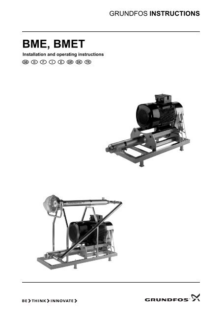
<strong>BME</strong>, <strong>BME</strong>T<br />
Installation and operating instructions<br />
GRUNDFOS INSTRUCTIONS
Declaration of Conformity<br />
We, <strong>Grundfos</strong>, declare under our sole responsibility that the products<br />
<strong>BME</strong> and <strong>BME</strong>T, to which this declaration relates, are in conformity with<br />
these Council directives on the approximation of the laws of the EC<br />
member states:<br />
— Machinery Directive (2006/42/EC).<br />
Standard used: EN 809: 2009.<br />
— Low Voltage Directive (2006/95/EC).<br />
Standard used: EN 60204-1: 2006.<br />
— EMC Directive (2004/108/EC).<br />
Standards used: EN 61000-6-2: 2005 and EN 61000-6-3: 2007.<br />
Déclaration de Conformité<br />
Nous, <strong>Grundfos</strong>, déclarons sous notre seule responsabilité, que les<br />
produits <strong>BME</strong> et <strong>BME</strong>T, auxquels se réfère cette déclaration, sont<br />
conformes aux Directives du Conseil concernant le rapprochement des<br />
législations des Etats membres CE relatives aux normes énoncées<br />
ci-dessous :<br />
— Directive Machines (2006/42/CE).<br />
Norme utilisée : EN 809 : 2009.<br />
— Directive Basse Tension (2006/95/CE).<br />
Norme utilisée : EN 60204-1: 2006.<br />
— Directive Compatibilité Electromagnétique CEM (2004/108/CE).<br />
Normes utilisées : EN 61000-6-2 : 2005 et EN 61000-6-3 : 2007.<br />
Declaración de Conformidad<br />
Nosotros, <strong>Grundfos</strong>, declaramos bajo nuestra entera responsabilidad que<br />
los productos <strong>BME</strong> y <strong>BME</strong>T, a los cuales se refiere esta declaración, están<br />
conformes con las Directivas del Consejo en la aproximación de las leyes<br />
de las Estados Miembros del EM:<br />
— Directiva de Maquinaria (2006/42/CE).<br />
Norma aplicada: EN 809: 2009.<br />
— Directiva de Baja Tensión (2006/95/CE).<br />
Norma aplicada: EN 60204-1: 2006.<br />
— Directiva EMC (2004/108/CE).<br />
Normas aplicadas: EN 61000-6-2: 2005 y EN 61000-6-3: 2007.<br />
Overensstemmelseserklæring<br />
Vi, <strong>Grundfos</strong>, erklærer under ansvar at produkterne <strong>BME</strong> og <strong>BME</strong>T som<br />
denne erklæring omhandler, er i overensstemmelse med disse af Rådets<br />
direktiver om indbyrdes tilnærmelse til EF-medlemsstaternes lovgivning:<br />
— Maskindirektivet (2006/42/EF).<br />
Anvendt standard: EN 809: 2009.<br />
— Lavspændingsdirektivet (2006/95/EF).<br />
Anvendt standard: EN 60204-1: 2006.<br />
— EMC-direktivet (2004/108/EF).<br />
Anvendte standarder: EN 61000-6-2: 2005: 2005 og<br />
EN 61000-6-3: 2007.<br />
2<br />
Konformitätserklärung<br />
Wir, <strong>Grundfos</strong>, erklären in alleiniger Verantwortung, dass die Produkte<br />
<strong>BME</strong> und <strong>BME</strong>T, auf die sich diese Erklärung bezieht, mit den folgenden<br />
Richtlinien des Rates zur Angleichung der Rechtsvorschriften der EU-<br />
Mitgliedsstaaten übereinstimmen:<br />
— Maschinenrichtlinie (2006/42/EG).<br />
Norm, die verwendet wurde: EN 809: 2009.<br />
— Niederspannungsrichtlinie (2006/95/EG).<br />
Norm, die verwendet wurde: EN 60204-1: 2006.<br />
— EMV-Richtlinie (2004/108/EG).<br />
Normen, die verwendet wurden: EN 61000-6-2: 2005 und<br />
EN 61000-6-3: 2007.<br />
Dichiarazione di Conformità<br />
<strong>Grundfos</strong> dichiara sotto la sua esclusiva responsabilità che i prodotti<br />
<strong>BME</strong> e <strong>BME</strong>T, ai quali si riferisce questa dichiarazione, sono conformi alle<br />
seguenti direttive del Consiglio riguardanti il riavvicinamento delle<br />
legislazioni degli Stati membri CE:<br />
— Direttiva Macchine (2006/42/CE).<br />
Norma applicata: EN 809: 2009.<br />
— Direttiva Bassa Tensione (2006/95/CE).<br />
Norma applicata: EN 60204-1: 2006.<br />
— Direttiva EMC (2004/108/CE).<br />
Norme applicate: EN 61000-6-2: 2005 e EN 61000-6-3: 2007.<br />
Δήλωση Συμμόρφωσης<br />
Εμείς, η <strong>Grundfos</strong>, δηλώνουμε με αποκλειστικά δική μας ευθύνη ότι τα<br />
προϊόντα <strong>BME</strong> και <strong>BME</strong>T στα οποία αναφέρεται η παρούσα δήλωση,<br />
συμμορφώνονται με τις εξής Οδηγίες του Συμβουλίου περί προσέγγισης<br />
των νομοθεσιών των κρατών μελών της ΕΕ:<br />
— Οδηγία για μηχανήματα (2006/42/EC).<br />
Πρότυπο που χρησιμοποιήθηκε: EN 809: 2009.<br />
— Οδηγία χαμηλής τάσης (2006/95/EC).<br />
Πρότυπο που χρησιμοποιήθηκε: EN 60204-1: 2006.<br />
— Οδηγία Ηλεκτρομαγνητικής Συμβατότητας (EMC) (2004/108/EC).<br />
Πρότυπα που χρησιμοποιήθηκαν: EN 61000-6-2: 2005 και<br />
EN 61000-6-3: 2007.<br />
Uygunluk Bildirgesi<br />
<strong>Grundfos</strong> olarak bu beyannameye konu olan <strong>BME</strong> ve <strong>BME</strong>T ürünlerinin, AB<br />
Üyesi Ülkelerin kanunlarını birbirine yaklaştırma üzerine Konsey<br />
Direktifleriyle uyumlu olduğunun yalnızca bizim sorumluluğumuz altında<br />
olduğunu beyan ederiz:<br />
— Makineler Yönetmeliği (2006/42/EC).<br />
Kullanılan standart: EN 809: 2009.<br />
— Düşük Voltaj Yönetmeliği (2006/95/EC).<br />
Kullanılan standart: EN 60204-1: 2006.<br />
— EMC Diretifi (2004/108/EC).<br />
Kullanılan standartlar: EN 61000-6-2: 2005 ve EN 61000-6-3: 2007.<br />
Bjerringbro, 10th May 2010<br />
Jan Strandgaard<br />
Technical Director<br />
<strong>Grundfos</strong> Holding A/S<br />
Poul Due Jensens Vej 7<br />
8850 Bjerringbro, Denmark<br />
Person authorised to compile technical file and<br />
empowered to sign the EC declaration of conformity.
<strong>BME</strong>, <strong>BME</strong>T<br />
Installation and operating instructions 4<br />
Montage- und Betriebsanleitung 17<br />
Notice d'installation et d'entretien 31<br />
Istruzioni di installazione e funzionamento 44<br />
Instrucciones de instalación y funcionamiento 57<br />
Οδηγίες εγκατάστασης και λειτουργίας 70<br />
Monterings- og driftsinstruktion 84<br />
Montaj ve kullanım kılavuzu 97<br />
3
Original installation and operating instructions.<br />
CONTENTS<br />
4<br />
Page<br />
1. Symbols used in this document 4<br />
2. General information 4<br />
2.1 Pumped liquids 4<br />
2.2 Preparation 5<br />
3. Installation 5<br />
3.1 Hose for turbine 5<br />
4. Pipe connection 6<br />
4.1 Inlet and discharge pipes 6<br />
5. Electrical connection 6<br />
6. Motor protection 6<br />
6.1 Thermistor 6<br />
6.2 Setting of motor starter 6<br />
6.3 Generator operation 6<br />
6.4 Monitoring of oil lubrication system 6<br />
7. Before starting the booster module 7<br />
8. Start-up 7<br />
8.1 <strong>BME</strong> 7<br />
8.2 <strong>BME</strong>T 7<br />
8.3 Operation settings 8<br />
9. Liquid filling, venting and checking of direction of<br />
rotation 8<br />
10. Checking of operation 8<br />
11. Pulleys and V-belts 8<br />
11.1 Inspection of pulleys 8<br />
12. Replacement of V-belts 9<br />
13. V-belt tension 9<br />
14. Using the tension tester 9<br />
15. Recommended V-belt tension 11<br />
15.1 V-belt tension, 50 Hz 11<br />
15.2 V-belt tension, 60 Hz 12<br />
16. Oil lubrication system 13<br />
16.1 Oil change 13<br />
16.2 Type of lubricating oil 13<br />
17. Motor bearings 14<br />
18. Shut-down procedure 14<br />
19. Periods of inactivity 14<br />
19.1 Preservation of pulleys and belts 14<br />
19.2 Start-up after a period of inactivity 14<br />
19.3 Removal of preservative before restarting 14<br />
19.4 Flushing of the modules 14<br />
20. Frequency of starts and stops 14<br />
21. Fault finding chart 15<br />
22. Checking of motor and cable 16<br />
23. Technical data 16<br />
24. Disposal 16<br />
1. Symbols used in this document<br />
Caution<br />
Note<br />
Warning<br />
Prior to installation, read these installation and<br />
operating instructions. Installation and operation<br />
must comply with local regulations and accepted<br />
codes of good practice.<br />
Warning<br />
If these safety instructions are not observed,<br />
it may result in personal injury!<br />
If these safety instructions are not observed,<br />
it may result in malfunction or damage to the<br />
equipment!<br />
Notes or instructions that make the job easier<br />
and ensure safe operation.<br />
2. General information<br />
<strong>Grundfos</strong> booster modules <strong>BME</strong> and <strong>BME</strong>T are supplied from the<br />
factory in boxes in which they should remain until they are to be<br />
installed. The modules are ready for installation.<br />
2.1 Pumped liquids<br />
Thin, non-explosive liquids, not containing solid particles or<br />
fibres. The liquid must not chemically attack the booster module<br />
materials. In case of doubt, contact <strong>Grundfos</strong>.<br />
It is recommended to filter the raw water to maximum 30 microns.<br />
The booster modules must never operate with water/liquid<br />
containing substances which would remove the surface tension,<br />
e.g. soap. If this type of detergent is used for cleaning of the<br />
system, the water/liquid must be led around the modules via a<br />
bypass.<br />
Caution<br />
Warning<br />
The booster modules must not be used for the<br />
pumping of inflammable liquids such as diesel<br />
oil, petrol or similar liquids.<br />
During transportation and storage, the booster<br />
modules must never be preserved with glycerine<br />
or similar liquids which are aggressive to the<br />
booster module materials.<br />
Fig. 1 <strong>BME</strong> booster module<br />
Fig. 2 <strong>BME</strong>T booster module<br />
Gr6721<br />
Gr6720
2.2 Preparation<br />
Before installation, the following checks should be made:<br />
1. Check for transport damages<br />
Make sure that the module has not been damaged during<br />
transportation.<br />
2. Type of booster module<br />
Check that the type designation corresponds to order, see<br />
module nameplate.<br />
3. Electricity supply<br />
The motor voltage and frequency details given on the<br />
nameplate should be compared with the actual electricity<br />
supply available.<br />
4. V-belt<br />
Check that the V-belt has been tightened, see section<br />
13. V-belt tension.<br />
5. Lubrication<br />
See section 17. Motor bearings.<br />
6. Oil level<br />
Check the oil level, see section 6.4 Monitoring of oil lubrication<br />
system.<br />
Note: During periods of inactivity, the oil container may be<br />
empty. Check the oil level after 5 minutes of operation.<br />
3. Installation<br />
The booster module can be mounted directly on the floor or<br />
on a base frame.The module is adjusted by means of the four<br />
adjustable feet.<br />
The inlet and discharge ports of the booster modules are shown<br />
in figs 3 and 4. Pipes are connected by means of Victaulic clamp<br />
couplings.<br />
The <strong>BME</strong>T booster module also has a PJE clamp coupling on the<br />
concentrate inlet and a connection (∅300) for a hose for the<br />
concentrate outlet.<br />
3.1 Hose for turbine<br />
On <strong>BME</strong>T systems, the hose (∅300) is fastened to the outlet of<br />
the turbine housing with a strap. The hose is led to a drain tank,<br />
drain channel or a similar drain.<br />
Caution<br />
The end of the hose should always be mounted above the highest<br />
possible water level in the drain. The hose should be supported,<br />
see fig. 4.<br />
Caution<br />
The concentrate outlet must be kept free under<br />
all operating conditions.<br />
If a discharge pipe is connected to the<br />
concentrate outlet, this pipe must have an air<br />
inlet.<br />
Fig. 3 <strong>BME</strong> booster module<br />
Inlet<br />
Discharge<br />
Adjustable feet ±10 mm Base frame<br />
TM02 6241 0103<br />
Fig. 4 <strong>BME</strong>T booster module<br />
If the module is to be fastened, the following procedure is<br />
recommended:<br />
Note<br />
Note<br />
Inlet<br />
Adjustable feet ±10 mm Base frame<br />
Fig. 5 Concrete foundation<br />
Fig. 6 Steel floor<br />
Fasten the module with four foundation bolts.<br />
The base frame has additional holes for this<br />
purpose. The bolts can be secured to a concrete<br />
foundation or welded onto a steel floor, see figs<br />
5 and 6.<br />
Prior to start-up, the nuts should be slackened,<br />
see fig. 5 concrete foundation and fig. 6 steel<br />
floor. The nuts must be counter-locked.<br />
Base frame<br />
Base frame<br />
The nuts must be tightened during transportation, see fig. 7.<br />
Fig. 7 Tightened nuts<br />
Concentrate<br />
inlet<br />
Base frame<br />
Discharge<br />
Concentrate outlet<br />
Nuts<br />
Min.<br />
∅450<br />
TM02 6242 0103<br />
TM01 1061 0203<br />
TM01 1064 0203<br />
TM01 1062 0203<br />
5
4. Pipe connection<br />
4.1 Inlet and discharge pipes<br />
The booster modules are fitted with clamp liners for Victaulic<br />
clamp couplings on the inlet and discharge sides. Position the<br />
clamp liners as shown in fig. 8.<br />
6<br />
Caution Avoid any stress in the pipe system.<br />
Fig. 8 Positioning of clamp liners<br />
5. Electrical connection<br />
Warning<br />
Before starting work on the booster module,<br />
make sure that the electricity supply has been<br />
switched off and that it cannot be accidentally<br />
switched on.<br />
The booster module must be connected to an<br />
external mains switch.<br />
The booster module must be earthed.<br />
The electrical connection must be carried out by an authorised<br />
electrician in accordance with local regulations and the diagrams<br />
for the motor protection, starter and monitoring devices used, see<br />
fig. 9. The electrical connections are made in the terminal box.<br />
Fig. 9 Wiring diagram<br />
3.5 mm<br />
Pipe system Clamp liners Booster module<br />
3UN2 100-0 C<br />
95 A1<br />
H1<br />
H2<br />
K<br />
N<br />
98 96 A2 T2 T1<br />
S1<br />
K1<br />
The required voltage quality measured at the motor terminals is<br />
± 5 % of the rated voltage during continuous operation.<br />
There must be voltage symmetry, i.e. approximately same<br />
difference of voltage between the individual phases, see section<br />
22. Checking of motor and cable, point 1.<br />
The motor is wound for star-delta starting.<br />
The following starting methods can be used:<br />
• star-delta starting,<br />
• soft starter or<br />
• frequency converter.<br />
FR<br />
N L1 L2 L3<br />
K1<br />
MV<br />
M<br />
3<br />
TM01 1066 3597<br />
TM02 5975 4502<br />
The maximum permissible run-up changeover time for star-delta<br />
starting is 2 seconds for motors up to and including 90 kW and<br />
4 seconds for motors of 110 to 160 kW.<br />
When starting up via a soft starter or frequency converter,<br />
the run-up time from 0 to 30 Hz should not exceed 6 seconds.<br />
The run-out time from 30 to 0 Hz should not exceed 6 seconds.<br />
During frequency converter operation, it is not advisable to run<br />
the motor at a frequency higher than the rated frequency<br />
(50 or 60 Hz), see motor nameplate.<br />
6. Motor protection<br />
The motor must be connected to an effective motor starter (MV)<br />
and an external amplifier relay (FR), see fig. 9. This protects the<br />
motor against damage from voltage drop, phase failure, quick and<br />
slow overloading and a locked rotor.<br />
In electricity supply systems where undervoltage and variations in<br />
phase symmetry may occur, a phase failure relay should be<br />
connected, see section 22. Checking of motor and cable.<br />
6.1 Thermistor<br />
Before starting up the system, the thermistors must be connected<br />
to terminals T1 and T2 on the terminal block, see fig. 9. The<br />
thermistors protect the motor windings against thermal overload.<br />
6.2 Setting of motor starter<br />
For cold motors, the tripping time for the motor starter must be<br />
less than 10 seconds at 5 times the rated current of the motor.<br />
To ensure the best protection of the motor, the setting of the<br />
motor starter should be carried out as follows:<br />
1. Set the starter overload to the rated current (I1/1) of the motor.<br />
2. Start the booster module and let it run for half an hour at<br />
normal performance.<br />
3. Slowly grade down the scale indicator until the motor starter<br />
trips out.<br />
4. Increase the overload setting by 5 %, but not higher than the<br />
rated current (I1/1).<br />
For motors wound for star-delta starting, the starter overload unit<br />
should be set as described above, but the maximum setting must<br />
not exceed the following:<br />
Starter overload setting = Rated current (I1/1) x 0.58.<br />
6.3 Generator operation<br />
Motor-driven generators for standard motors are often available<br />
according to standard conditions, e.g.<br />
• maximum height above sea level: 150 metres<br />
• maximum air intake temperature: 30 °C<br />
• maximum air humidity: 60 %.<br />
6.4 Monitoring of oil lubrication system<br />
The oil lubrication system is monitored by a level switch<br />
positioned as shown in fig. 10. The electrical connection to<br />
0-250 V (with a maximum 10 A back-up fuse) is made in the<br />
terminal box.<br />
Note<br />
During periods of inactivity, the oil container may<br />
be empty. Check the oil level after 5 minutes of<br />
operation. If necessary, refill the oil container.
Max. oil level<br />
Min. oil level<br />
Terminal box<br />
Fig. 10 Oil lubrication system<br />
Level switch<br />
7. Before starting the booster module<br />
Check the following:<br />
1. Oil level, see section 6.4 Monitoring of oil lubrication system.<br />
2. Belt tension, see section 13. V-belt tension.<br />
3. Greasing, see section 17. Motor bearings.<br />
4. Electricity supply in accordance with nameplate.<br />
5. Free movability.<br />
Rotate the motor and pump shafts manually by means of the<br />
V-belt.<br />
6. Pipework according to the diagrams in figs 11 and 12.<br />
7. Slacken the foundation bolt nuts.<br />
8. <strong>BME</strong>T: Free discharge for the concentrate.<br />
Connection of concentrate hose, see fig. 4.<br />
8. Start-up<br />
It is recommended to open the discharge valve 1/4 when starting<br />
the booster module.<br />
8.1 <strong>BME</strong><br />
To start up a <strong>BME</strong> booster module, proceed as follows:<br />
1. Start the feed pump and check that the inlet pressure of the<br />
booster module is higher than 1.0 bar (10 metres head) and<br />
lower than 30.0 bar (300 metres head).<br />
2. Vent the booster module, see section 9. Liquid filling, venting<br />
and checking of direction of rotation.<br />
3. Start the high-pressure pump.<br />
Check that the oil level in the oil container stabilises between<br />
minimum and maximum.<br />
4. Check the direction of rotation as described in section<br />
9. Liquid filling, venting and checking of direction of rotation.<br />
5. Set the discharge pressure of the booster module to the<br />
desired value.<br />
6. Check that the inlet pressure of the booster module is higher<br />
than 1.0 bar (10 metres head) and lower than 30.0 bar<br />
(300 metres head).<br />
The booster module is now ready for operation.<br />
TM01 1411 4497<br />
Air escape valve<br />
Fig. 11 <strong>BME</strong> booster system<br />
8.2 <strong>BME</strong>T<br />
To start up a <strong>BME</strong>T booster module, proceed as follows:<br />
1. Start the feed pump and check that the inlet pressure of the<br />
booster module is higher than 2.0 bar (20 metres head) and<br />
lower than 5.0 bar (50 metres head).<br />
2. Vent the booster module, see section 9. Liquid filling, venting<br />
and checking of direction of rotation.<br />
The module is fully vented when liquid runs out of the air<br />
escape valve.<br />
3. Start the high-pressure pump.<br />
Check that the oil level in the oil container stabilises between<br />
minimum and maximum.<br />
4. Check the direction of rotation as described in section<br />
9. Liquid filling, venting and checking of direction of rotation.<br />
5. Set the discharge pressure of the booster module to the<br />
desired value.<br />
6. Check that the inlet pressure of the booster module is higher<br />
than 2.0 bar (20 metres head) and lower than 5.0 bar<br />
(50 metres head).<br />
The booster module is now ready for operation.<br />
Air escape valve<br />
Turbine pump<br />
Low-pressure<br />
switch<br />
Feed pump<br />
Raw-water<br />
supply<br />
Fig. 12 <strong>BME</strong>T booster system<br />
High-pressure switch<br />
RO filter<br />
High-pressure pump<br />
Low-pressure<br />
switch<br />
Feed pump<br />
Raw-water<br />
supply<br />
Permeate<br />
Concentrate<br />
(brine)<br />
High-pressure switch<br />
RO filter<br />
High-pressure pump<br />
Turbine<br />
Concentrate<br />
(brine)<br />
Pressure<br />
regulating<br />
valve<br />
Permeate<br />
TM01 1084 3697<br />
TM01 1085 3697<br />
7
8.3 Operation settings<br />
The flow and discharge pressure of the booster module should<br />
always be kept within the ranges for which it was originally<br />
designed, see "Technical specification" supplied with the system.<br />
If the system requires flows and pressures outside the design<br />
range, changes are possible. Please contact <strong>Grundfos</strong>.<br />
9. Liquid filling, venting and checking of<br />
direction of rotation<br />
Procedure:<br />
1. Open the valve on the inlet side of the module. The module is<br />
normally primed by the pressure from the feed pump.<br />
2. Open the air escape valve on the discharge side of the<br />
module.<br />
3. Continue the filling procedure until water runs out of the air<br />
escape valve, see figs 11 and 12.<br />
4. If the system is fitted with an isolating valve on the discharge<br />
side of the high-pressure pump, open this valve approx. 1/4.<br />
5. Start the module (for 1 sec. only) and check the direction of<br />
rotation. The correct direction of rotation is indicated on the<br />
cover of the V-belt screen. If necessary, interchange two<br />
phases to the motor.<br />
The direction of rotation of the turbine-driven pump is always<br />
correct.<br />
10. Checking of operation<br />
Check the following at suitable intervals:<br />
• Flow and pressure.<br />
• Current consumption.<br />
• Lubricating oil level.<br />
• Whether the oil container contains water (the lubricating oil<br />
should be changed every 2,000 operating hours or every<br />
6 months, whichever comes first).<br />
• Whether the motor ball bearings are being greased (check that<br />
excessive grease can escape through the drain hole in<br />
bearing cover).<br />
• Whether the bearings are worn.<br />
• Whether the V-belts are tightened correctly.<br />
Check every 6 months, see section 13. V-belt tension.<br />
• Whether the shaft seal is leaky.<br />
The drain hole underneath the pulley must be free from<br />
deposits. Flush with clean fresh water, if required.<br />
The shaft seal is lubricated by the pumped liquid. Small<br />
quantities of liquid are therefore drained via the drain hole.<br />
• Whether the noise level has changed.<br />
It is recommended to write the operating data into the log book<br />
supplied with the system. These data can be useful for<br />
maintenance purpose.<br />
8<br />
11. Pulleys and V-belts<br />
11.1 Inspection of pulleys<br />
Inspect the pulley grooves for wear, see fig. 13. Belt life will be<br />
reduced if the grooves are worn.<br />
Fig. 13 Examples of new and worn pulley grooves<br />
Use, for instance, pulley gauges to determine whether the<br />
grooves are worn, see fig. 14.<br />
The motor pulley groove is 38 ° and the pump pulley groove is<br />
34 °.<br />
Fig. 14 Use of pulley gauges<br />
A torch may be useful when inspecting the grooves. Do not be<br />
misled by shiny grooves. Grooves that are shiny are often<br />
polished because of heavy wear. Inspect the pulley grooves for<br />
corrosion or pitting. If corroded or pitted surfaces are found, the<br />
pulley should be replaced.<br />
Caution<br />
Wear<br />
New V-belt and pulley groove<br />
Worn V-belt and pulley groove<br />
Worn pulleys must be replaced to ensure troublefree<br />
operation.<br />
Checking and correcting pulley alignment<br />
Misaligned pulleys will accelerate wear of belts and pulley<br />
grooves.<br />
Check the alignment by placing a steel straightedge across the<br />
pulley faces so that it touches all four contact points, see fig. 15.<br />
Correct the alignment, if required.<br />
Fig. 15 Correct alignment<br />
Pulley gauges<br />
TM03 4742 2706<br />
TM03 5330 3306<br />
TM03 5831 4006
12. Replacement of V-belts<br />
Procedure:<br />
Caution All V-belts must be replaced by new belts.<br />
1. Remove oil and impurities from the pulley grooves.<br />
2. Place the V-belts loosely in the pulley grooves without using<br />
force or tools of any kind.<br />
3. Adjust the V-belt tension to the value stated in section<br />
15. Recommended V-belt tension.<br />
13. V-belt tension<br />
Correct belt tension is decisive for long and trouble-free operation<br />
of the transmission unit.<br />
This section refers to section 15. Recommended V-belt tension.<br />
1. Move the motor towards or away from the pump until the<br />
correct tension has been obtained, i.e. between Tmin.-Tmax.. 2. Rotate the motor and pump shafts a few times by means of the<br />
V-belt before checking the Tmin.-Tmax. value.<br />
3. Adjust the V-belt tension to the value stated.<br />
4. Check the V-belt tension after 1 to 4 hours of operation at full<br />
load.<br />
5. Adjust the V-belt tension to the value stated.<br />
6. The belt tension should be checked regularly according to<br />
the recommended values.<br />
The belt tension can be measured through a hole in the protective<br />
guard.<br />
V-belts and pulleys must be checked every 6 months.<br />
It is recommended to replace the V-belts once a year.<br />
14. Using the tension tester<br />
The tension tester supplied with the <strong>BME</strong> and <strong>BME</strong>T should be<br />
used as described below.<br />
The use of the tension tester is illustrated in figs 16, 17 and 18.<br />
The position numbers in this section refer to fig. 16.<br />
1. Rotate the motor and pump shafts a few times before checking<br />
the belt tension.<br />
2. Reset the pointer, pos. 1, and place the tension tester on the<br />
belt between the pulleys, pos. 4.<br />
3. Use only one finger to operate the tension tester, pos. 2.<br />
4. Gently press the tension tester until a "click" indicates that the<br />
tester has been activated.<br />
5. Remove the tester from the belt and read the tension<br />
measured, pos. 3.<br />
6. Adjust the V-belt tension to the value stated in section<br />
15. Recommended V-belt tension.<br />
Caution<br />
Rotate the motor and pump shafts after each<br />
tension adjustment.<br />
9
10<br />
1<br />
2<br />
3<br />
4<br />
Fig. 16 Tension tester<br />
Fig. 17 Using the tension tester<br />
TM03 4749 2606<br />
TM03 8109 0107<br />
Fig. 18 Reading the tension tester<br />
TM03 8110 0107
15. Recommended V-belt tension<br />
15.1 V-belt tension, 50 Hz<br />
The table below shows the recommended tension of V-belts for <strong>BME</strong> and <strong>BME</strong>T:<br />
Diameter<br />
of pulley<br />
[mm]<br />
Number<br />
of V-belts<br />
Belt<br />
length<br />
Motor Pump [mm]<br />
* V-belt tension within the first hour of operation.<br />
V-belt tension<br />
[N]<br />
New belts*<br />
T min.-T max.<br />
160 kW, 50 Hz, 400 V, 2976 min -1<br />
** V-belt tension after more than one hour of operation.<br />
V-belt tension, 50 Hz<br />
Check**<br />
T min.-T max.<br />
Diameter<br />
of pulley<br />
[mm]<br />
Number<br />
of V-belts<br />
Belt<br />
length<br />
Motor Pump [mm]<br />
V-belt tension<br />
[N]<br />
New belts*<br />
T min.-T max.<br />
55 kW, 50 Hz, 400 V, 2960 min -1<br />
300<br />
280<br />
265<br />
250<br />
236<br />
150 9<br />
1650<br />
1600<br />
1550<br />
900-1000<br />
800-900<br />
650-700<br />
600-700<br />
300<br />
280<br />
265<br />
250<br />
236 150 4<br />
1500<br />
1400<br />
800-900<br />
700-800<br />
224 224<br />
132 kW, 50 Hz, 400 V, 2977 min-1 212<br />
300<br />
1650 850-900 650-700 200<br />
1320 600-700<br />
280<br />
190<br />
265<br />
1600<br />
800-900<br />
45 kW, 50 Hz, 400 V, 2970 min<br />
150 8<br />
600-700<br />
-1<br />
250<br />
236<br />
1550<br />
300<br />
280<br />
1500<br />
800-900<br />
224 700-800<br />
265<br />
1400<br />
212 1500 250<br />
110 kW, 50 Hz, 400 V, 2979 min 150 3<br />
700-800<br />
-1<br />
236<br />
300<br />
1650 900-1000 700-800 224<br />
1320<br />
280<br />
265<br />
250 150<br />
6 1600<br />
800-900<br />
650-700<br />
212<br />
200<br />
190<br />
1250<br />
236<br />
1550<br />
37 kW, 50 Hz, 400 V, 2955 min<br />
8 700-800<br />
-1<br />
224<br />
212 1500<br />
500-600<br />
300<br />
280<br />
1400 800-900<br />
90 kW, 50 Hz, 400 V, 2970 min<br />
150 3<br />
-1 265<br />
300<br />
280<br />
265<br />
1550 800-900<br />
600-700<br />
250<br />
236<br />
224<br />
1320 700-800<br />
250<br />
236 150 6<br />
1500<br />
212<br />
200<br />
1250 600-700<br />
224<br />
212<br />
1450<br />
700-800<br />
500-600<br />
190<br />
30 kW, 50 Hz, 400 V, 2955 min -1<br />
200<br />
190<br />
1400<br />
300<br />
280<br />
1400<br />
800-900<br />
75 kW, 50 Hz, 400 V, 2974 min<br />
150 2<br />
700-800<br />
-1<br />
265<br />
300<br />
280<br />
265<br />
1550 800-900<br />
600-700<br />
250<br />
236<br />
224<br />
1320<br />
250<br />
236 150 5<br />
1500<br />
212<br />
200<br />
1250<br />
224<br />
212<br />
1450<br />
700-800<br />
500-600<br />
190<br />
200<br />
190<br />
1400<br />
Check**<br />
T min.-T max.<br />
600-700<br />
500-600<br />
600-700<br />
500-600<br />
600-700<br />
500-600<br />
400-500<br />
600-700<br />
500-600<br />
11
15.2 V-belt tension, 60 Hz<br />
The table below shows the recommended tension of V-belts for <strong>BME</strong> and <strong>BME</strong>T:<br />
* V-belt tension within the first hour of operation.<br />
** V-belt tension after more than one hour of operation.<br />
12<br />
Diameter<br />
of pulley<br />
[mm]<br />
Number<br />
of V-belts<br />
Belt<br />
length<br />
V-belt tension<br />
[N]<br />
V-belt tension, 60 Hz<br />
Diameter<br />
of pulley<br />
[mm]<br />
Number<br />
of V-belts<br />
Belt<br />
length<br />
V-belt tension<br />
[N]<br />
Motor Pump [mm]<br />
New belts*<br />
Tmin.-Tmax.<br />
Check**<br />
Tmin.-Tmax.<br />
Motor Pump [mm]<br />
New belts*<br />
Tmin.-Tmax.<br />
Check**<br />
Tmin.-Tmax.<br />
150 kW, 60 Hz, 440 V, 3572 min-1 52 kW, 60 Hz, 440 V, 3564 min-1 250<br />
236<br />
224<br />
850-900<br />
1550<br />
150 9<br />
800-900<br />
1500<br />
125 kW, 60 Hz, 440 V, 3575 min<br />
650-700<br />
250<br />
236<br />
224<br />
150<br />
4<br />
1400<br />
1320<br />
800-900<br />
600-700<br />
-1 212<br />
250<br />
236<br />
1550<br />
850-900 650-700 200<br />
190<br />
1250<br />
700-800<br />
224<br />
800-900<br />
180 5 600-700 500-600<br />
212 150 8 1500<br />
600-700<br />
43 kW, 60 Hz, 440 V, 3546 min -1<br />
200<br />
190<br />
180<br />
700-800<br />
1450<br />
103 kW, 60 Hz, 440 V, 3564 min<br />
250<br />
236<br />
224<br />
1320 800-900<br />
150 3<br />
1250 700-800<br />
600-700<br />
-1 212<br />
250<br />
236<br />
6<br />
1500 900-1000<br />
800-900<br />
700-800 200<br />
190 500-600<br />
224<br />
1450<br />
650-700<br />
35 kW, 60 Hz, 440 V, 3546 min<br />
150<br />
8<br />
700-800<br />
-1<br />
212<br />
200<br />
190<br />
180<br />
1400<br />
600-700<br />
500-600<br />
250<br />
236<br />
224<br />
212<br />
150<br />
2 1320<br />
900-1000<br />
800-900<br />
700-800<br />
700-800<br />
600-700<br />
86 kW, 60 Hz, 440 V, 3568 min<br />
3 1250<br />
500-600<br />
-1<br />
200<br />
600-700<br />
250<br />
236<br />
224<br />
5<br />
1500<br />
1450<br />
800-900<br />
650-700<br />
600-700<br />
190<br />
212 150<br />
200<br />
190<br />
180<br />
6<br />
1400<br />
700-800<br />
500-600<br />
63 kW, 60 Hz, 440 V, 3568 min -1<br />
250<br />
1450<br />
236<br />
224<br />
212 150<br />
4<br />
1400 800-900<br />
600-700<br />
200<br />
190<br />
1320 700-800<br />
180 5 600-700 500-600
16. Oil lubrication system<br />
The <strong>BME</strong> and <strong>BME</strong>T booster modules have an oil lubrication<br />
system for the two ball bearings in the pulley head.<br />
During operation, there must be a continuous flow of oil to the oil<br />
container. Check the flow by looking into the container,<br />
see fig. 19.<br />
Max. oil level<br />
Min. oil level<br />
Terminal box<br />
Oil container<br />
Pulley head<br />
Fig. 19 Oil lubrication system<br />
Oil cooler<br />
16.1 Oil change<br />
The hydraulic oil should be changed every 2,000 operating hours<br />
or every 6 months, whichever comes first. Total quantity of oil:<br />
Approx. 1.5 litres.<br />
During operation, the oil must be changed as follows:<br />
1. Switch off the level switch in the oil container or establish a<br />
time delay of approx. 10 minutes.<br />
2. Open the drain valve, see fig. 19. Oil will now run out of the<br />
oil drain pipe.<br />
3. Close the drain valve when the oil container is almost empty.<br />
4. Fill in new oil up to the maximum level mark on the oil<br />
container.<br />
5. Open the drain valve.<br />
6. Close the drain valve when the oil container is almost empty.<br />
7. Fill in oil up to the maximum level mark on the oil container.<br />
8. Open the drain valve.<br />
9. Close the drain valve when the oil container is almost empty.<br />
10. Fill in oil up to the maximum level mark on the oil container.<br />
Approx. 1.5 litres of hydraulic oil has now been filled into the<br />
container.<br />
11. Check the oil level after 1 to 2 hours of operation and refill,<br />
if required.<br />
The oil has now been changed.<br />
Drain valve Oil drain pipe<br />
If the oil lubrication system has been dismantled during<br />
repair, the system must be filled as follows:<br />
1. Check that the drain valve is closed, see fig. 19.<br />
2. Fill new oil into the oil container, approx. 0.5 litres, and wait<br />
approx. 10 minutes until the oil level has fallen.<br />
3. Fill in oil up to the maximum level mark on the oil container.<br />
4. Start up the booster module.<br />
The oil level in the oil container will now fall.<br />
5. During operation, fill in oil up to the maximum level mark on<br />
the oil container.<br />
6. Check the oil level after 1 to 2 hours of operation and refill,<br />
if required.<br />
During operation, the oil level in the container must lie<br />
between the minimum and maximum marks.<br />
During inactivity, the oil level in the container may fall below<br />
the minimum mark.<br />
The oil lubrication system is now filled with oil.<br />
16.2 Type of lubricating oil<br />
The oil system is factory-filled with hydraulic oil, type Mobil<br />
DTE 24.<br />
Other types of hydraulic oil with a viscosity of 32 can be used.<br />
TM01 1410 4497<br />
13
17. Motor bearings<br />
Under optimum operating conditions, the operating life of the<br />
motor ball bearings is approx. 20,000 operating hours. After that<br />
period, the bearings must be replaced. The new ball bearings<br />
must be filled with grease.<br />
<strong>BME</strong> and <strong>BME</strong>T booster modules are factory-fitted with a manual<br />
motor bearing greasing system. For greasing intervals, etc., see<br />
motor nameplate or the installation and operating instructions<br />
supplied with the motor.<br />
18. Shut-down procedure<br />
See section 19. Periods of inactivity for precautions to be taken<br />
when shutting down the system. These precautions must be<br />
taken to protect the system and ensure long life of all the system<br />
components.<br />
Procedure<br />
See fig. 11 or 12.<br />
1. Stop the <strong>BME</strong> pump (high-pressure pump).<br />
2. Wait for 5 seconds to ensure water supply while the <strong>BME</strong><br />
pump is being shut down.<br />
3. Stop the feed pump.<br />
19. Periods of inactivity<br />
In the case of periods of inactivity, various precautions must be<br />
taken to protect the system.<br />
The precautions to be taken if the system is to be inactive for<br />
a certain period appear in the table:<br />
Action<br />
Flushing, see section 19.4 x x x x<br />
Fill the modules with fresh water x x x x<br />
Preserve the pump*<br />
Slacken and remove the V-belts.<br />
x x x<br />
Preserve the pulleys against<br />
corrosion, see section 19.1<br />
x x x<br />
Rotate pump and motor shafts<br />
manually once a month<br />
x x<br />
* Use the same solution that is used to preserve the membranes.<br />
19.1 Preservation of pulleys and belts<br />
When the belts have been removed, lubricate the pulleys with an<br />
anti-corrosive lubricating oil.<br />
The belts must be kept at a temperature not exceeding 30 °C and<br />
at a relative air humidity not exceeding 70 %.<br />
The belts must not be exposed to direct sunlight.<br />
19.2 Start-up after a period of inactivity<br />
The precautions to be taken if the system has been inactive for a<br />
certain period appear in the table:<br />
14<br />
Caution<br />
Action<br />
30 minutes<br />
1 month<br />
3 months<br />
The normal stop procedure must be followed<br />
step by step.<br />
Remove preservative from the pulleys,<br />
see section 19.3<br />
x x x<br />
Check the V-belts x x x<br />
Mount the V-belts and adjust the tension<br />
according to the values in section 15.<br />
x x x<br />
Caution<br />
1 month<br />
3 months<br />
6 months<br />
6 months<br />
The normal start-up procedure must be followed<br />
step by step. For greasing of motor bearings, see<br />
section 17. Motor bearings.<br />
19.3 Removal of preservative before restarting<br />
Before restarting the system, remove the preservative with a<br />
suitable solvent. The pulleys must be completely free from oil<br />
before the belt is refitted.<br />
19.4 Flushing of the modules<br />
The booster pumps must be stopped while the system is flushed.<br />
The booster modules can be flushed through in or against the<br />
flow direction, see fig. 20 or 21.<br />
Flush the system through with fresh water for approx. 10 minutes<br />
or until the salinity is below 500 ppm. The pressure during<br />
flushing must be minimum 2 bar. The flushing must be continued<br />
until the modules are completely filled with clean fresh water.<br />
Caution<br />
Caution<br />
Caution<br />
Caution<br />
If the flushing takes more than 10 minutes, the<br />
flow must be reduced to maximum 10 % of the<br />
rated flow.<br />
The booster modules must be filled with clean<br />
fresh water during periods of inactivity.<br />
To flush the pulley head of the <strong>BME</strong> pump, start<br />
the pump for 30 seconds to allow the fresh water<br />
to enter into the pulley head.<br />
The distributing pipe for nozzles must also be<br />
flushed through.<br />
Fig. 20 <strong>BME</strong> booster module – flow direction when flushing<br />
Fig. 21 <strong>BME</strong>T booster module – flow direction when flushing<br />
20. Frequency of starts and stops<br />
Minimum 1 per year is recommended.<br />
Maximum 5 per hour.<br />
Maximum 20 per day.<br />
TM01 1386 0403<br />
TM01 1387 0403
21. Fault finding chart<br />
Warning<br />
Before starting work on the booster module, make sure that the electricity supply has been switched off and that it<br />
cannot be accidentally switched on.<br />
Fault Possible cause Remedy<br />
1. The booster module<br />
starts/stops<br />
occasionally during<br />
operation.<br />
2. The booster module<br />
stops during operation.<br />
3. The booster module<br />
runs, but gives no<br />
water or develops any<br />
pressure.<br />
4. The booster module<br />
runs at reduced<br />
capacity.<br />
a) No water supply.<br />
The low-pressure switch has cut out.<br />
Check that the low-pressure switch functions normally<br />
and is adjusted correctly. Check that the minimum inlet<br />
pressure is correct. If not, check the feed pump, see<br />
section 8. Start-up.<br />
b) The lubricating oil level is too low. Check that the oil level switch functions normally. If it is<br />
OK, check the oil system for leakage, see section<br />
16. Oil lubrication system.<br />
a) The fuses are blown. After a cut-out, the cause of a possible short-circuit<br />
must be found.<br />
If the fuses are blown, check whether the motor starter<br />
has been set correctly or is faulty.<br />
If the fuses are hot when they are replaced, check that<br />
the load of the individual phases does not exceed the<br />
motor current during operation. Identify the cause of the<br />
load.<br />
If the fuses are not hot immediately after the cut-out, the<br />
cause of a possible short-circuit must be identified.<br />
Possible fuses in the control circuit must be checked<br />
and defective fuses must be replaced.<br />
b) The motor starter overload unit has tripped<br />
out.<br />
c) The magnetic coil of motor starter/contactor<br />
is defective (not cutting in).<br />
Reset the starter overload, see also sections<br />
5. Electrical connection, 6. Motor protection and<br />
7. Before starting the booster module.<br />
Replace the coil. Check the coil voltage.<br />
d) The control circuit has cut out or is defective. Check the control circuit and the contacts in the<br />
monitoring devices (low-pressure switch, flow switch,<br />
etc.).<br />
e) The motor/supply cable is defective. Check motor and cable, see section 6.2 Setting of motor<br />
starter.<br />
a) No or insufficient water supply at the module<br />
inlet.<br />
b) The piping system, pump or nozzle is<br />
choked up.<br />
Check that the inlet pressure during operation is at least<br />
1 bar for <strong>BME</strong> and 2 bar for <strong>BME</strong>T, see sections<br />
8.1 <strong>BME</strong> and 8.2 <strong>BME</strong>T.<br />
Restart the booster module as described in section<br />
8. Start-up.<br />
Check the function of the feed pump.<br />
Check the piping system, pump and nozzle.<br />
c) The pre-filter is choked up. Clean the pre-filter.<br />
a) Wrong direction of rotation. See section 9. Liquid filling, venting and checking of<br />
direction of rotation.<br />
b) The valves on the discharge side are partly<br />
closed or blocked.<br />
Check the valves.<br />
c) The discharge pipe is partly blocked by<br />
impurities.<br />
Clean or replace the discharge pipe. Measure the<br />
discharge pressure and compare the value with the<br />
calculated data, see "Technical specification", supplied<br />
with the system.<br />
d) The pump is partly blocked by impurities. Pull the pump out of the sleeve. Dismantle, clean and<br />
check the pump and module. Replace any defective<br />
parts.<br />
e) The pump is defective. Pull the pump out of the sleeve. Dismantle, clean and<br />
check the pump and module. Replace any defective<br />
parts.<br />
f) The pre-filter is choked up. Clean the pre-filter.<br />
15
22. Checking of motor and cable<br />
1. Supply voltage<br />
2. Current consumption<br />
23. Technical data<br />
See motor and module nameplates.<br />
24. Disposal<br />
This product or parts of it must be disposed of in an<br />
environmentally sound way:<br />
1. Use the public or private waste collection service.<br />
2. If this is not possible, contact the nearest <strong>Grundfos</strong> company<br />
or service workshop.<br />
16<br />
TM00 1371 3597<br />
TM00 1372 3597<br />
TM00 1373 3597<br />
Measure the voltage between the phases with<br />
a voltmeter.<br />
Connect the voltmeter to the terminals in the<br />
motor starter.<br />
Measure the current of each phase while the<br />
module is operating at a constant discharge<br />
pressure (if possible at the capacity where the<br />
motor is most heavily loaded).<br />
For normal operating current, see the<br />
"Technical specification".<br />
The voltage should, when the motor is loaded, be<br />
within ± 5 % of the rated voltage. The motor may burn if<br />
there are larger variations in voltage.<br />
If the voltage is constantly too high or too low, the motor<br />
must be replaced by one corresponding to the supply<br />
voltage.<br />
Large variations in the supply voltage indicate poor<br />
electricity supply, and the module should be stopped<br />
until the defect has been found.<br />
Resetting of the motor starter may be necessary.<br />
The difference between the current of the phase with<br />
the highest amp consumption and the one with the<br />
lowest amp consumption must not exceed 10 % of the<br />
lowest amp consumption.<br />
If so, or if the current exceeds the full-load current,<br />
check these possible faults:<br />
• A damaged pump is causing the motor to be<br />
overloaded. Pull the pump out of the sleeve for<br />
overhaul.<br />
• The motor windings are short-circuited or partly<br />
disjointed.<br />
• Too high or too low supply voltage.<br />
• Poor connection in leads. Weak cables.<br />
Points 3 and 4: Measurement not needed if supply voltage and current consumption are normal.<br />
3. Winding resistance<br />
Remove the phase leads from the terminal The highest value must not exceed the lowest value by<br />
box.<br />
more than 5 %.<br />
Measure the winding resistance as shown on If the deviation is higher, and the supply cable is OK,<br />
the drawing.<br />
the motor should be overhauled.<br />
4. Insulation resistance<br />
TM00 1374 3597<br />
Remove the phase leads from the terminal<br />
box.<br />
Measure the insulation resistance from each<br />
phase to earth (frame).<br />
(Make sure that the earth connection is made<br />
carefully.)<br />
The insulation resistance for a new, cleaned or repaired<br />
motor must be approx. 10 MΩ measured to earth.<br />
For a given motor the critical insulation resistance<br />
(R crit) can be calculated as follows:<br />
Rcrit = UN [kV] x 0.5 [MΩ/kV].<br />
If the measured insulation resistance is lower than R crit,<br />
the motor must be overhauled.<br />
Subject to alterations.
LOG BOOK for <strong>BME</strong>/<strong>BME</strong>T booster modules<br />
Product no: Installation date: Company/your ref.<br />
Country:<br />
Type: Start of operation: City:<br />
Date<br />
Amb.<br />
temp.<br />
Liquid<br />
temp.<br />
Feed flow/<br />
pressure<br />
Concent.<br />
flow/<br />
pressure<br />
VFD/Soft start:<br />
Brand<br />
Permeate<br />
flow<br />
Current<br />
[A]<br />
Voltage<br />
[V]<br />
Comments<br />
111
System sketch<br />
112
Argentina<br />
Bombas GRUNDFOS de Argentina<br />
S.A.<br />
Ruta Panamericana km. 37.500 Lote<br />
34A<br />
1619 - Garin<br />
Pcia. de Buenos Aires<br />
Phone: +54-3327 414 444<br />
Telefax: +54-3327 411 111<br />
Australia<br />
GRUNDFOS Pumps Pty. Ltd.<br />
P.O. Box 2040<br />
Regency Park<br />
South Australia 5942<br />
Phone: +61-8-8461-4611<br />
Telefax: +61-8-8340 0155<br />
Austria<br />
GRUNDFOS Pumpen Vertrieb<br />
Ges.m.b.H.<br />
<strong>Grundfos</strong>straße 2<br />
A-5082 Grödig/Salzburg<br />
Tel.: +43-6246-883-0<br />
Telefax: +43-6246-883-30<br />
Belgium<br />
N.V. GRUNDFOS Bellux S.A.<br />
Boomsesteenweg 81-83<br />
B-2630 Aartselaar<br />
Tél.: +32-3-870 7300<br />
Télécopie: +32-3-870 7301<br />
Belorussia<br />
Представительство ГРУНДФОС в<br />
Минске<br />
220123, Минск,<br />
ул. В. Хоружей, 22, оф. 1105<br />
Тел.: +(37517) 233 97 65,<br />
Факс: +(37517) 233 97 69<br />
E-mail: grundfos_minsk@mail.ru<br />
Bosnia/Herzegovina<br />
GRUNDFOS Sarajevo<br />
Trg Heroja 16,<br />
BiH-71000 Sarajevo<br />
Phone: +387 33 713 290<br />
Telefax: +387 33 659 079<br />
e-mail: grundfos@bih.net.ba<br />
Brazil<br />
BOMBAS GRUNDFOS DO BRASIL<br />
Av. Humberto de Alencar Castelo<br />
Branco, 630<br />
CEP 09850 - 300<br />
São Bernardo do Campo - SP<br />
Phone: +55-11 4393 5533<br />
Telefax: +55-11 4343 5015<br />
Bulgaria<br />
GRUNDFOS Pumpen Vertrieb<br />
Representative Office - Bulgaria<br />
Bulgaria, 1421 Sofia<br />
Lozenetz District<br />
105-107 Arsenalski blvd.<br />
Phone: +359 2963 3820, 2963 5653<br />
Telefax: +359 2963 1305<br />
Canada<br />
GRUNDFOS Canada Inc.<br />
2941 Brighton Road<br />
Oakville, Ontario<br />
L6H 6C9<br />
Phone: +1-905 829 9533<br />
Telefax: +1-905 829 9512<br />
China<br />
GRUNDFOS Pumps (Shanghai) Co.<br />
Ltd.<br />
51 Floor, Raffles City<br />
No. 268 Xi Zang Road. (M)<br />
Shanghai 200001<br />
PRC<br />
Phone: +86-021-612 252 22<br />
Telefax: +86-021-612 253 33<br />
Croatia<br />
GRUNDFOS CROATIA d.o.o.<br />
Cebini 37, Buzin<br />
HR-10010 Zagreb<br />
Phone: +385 1 6595 400<br />
Telefax: +385 1 6595 499<br />
www.grundfos.hr<br />
Czech Republic<br />
GRUNDFOS s.r.o.<br />
Čajkovského 21<br />
779 00 Olomouc<br />
Phone: +420-585-716 111<br />
Telefax: +420-585-716 299<br />
Denmark<br />
GRUNDFOS DK A/S<br />
Martin Bachs Vej 3<br />
DK-8850 Bjerringbro<br />
Tlf.: +45-87 50 50 50<br />
Telefax: +45-87 50 51 51<br />
E-mail: info_GDK@grundfos.com<br />
www.grundfos.com/DK<br />
Estonia<br />
GRUNDFOS Pumps Eesti OÜ<br />
Peterburi tee 92G<br />
11415 Tallinn<br />
Tel: + 372 606 1690<br />
Fax: + 372 606 1691<br />
Finland<br />
OY GRUNDFOS Pumput AB<br />
Mestarintie 11<br />
FIN-01730 Vantaa<br />
Phone: +358-3066 5650<br />
Telefax: +358-3066 56550<br />
France<br />
Pompes GRUNDFOS Distribution S.A.<br />
Parc d’Activités de Chesnes<br />
57, rue de Malacombe<br />
F-38290 St. Quentin Fallavier (Lyon)<br />
Tél.: +33-4 74 82 15 15<br />
Télécopie: +33-4 74 94 10 51<br />
Germany<br />
GRUNDFOS GMBH<br />
Schlüterstr. 33<br />
40699 Erkrath<br />
Tel.: +49-(0) 211 929 69-0<br />
Telefax: +49-(0) 211 929 69-3799<br />
e-mail: infoservice@grundfos.de<br />
Service in Deutschland:<br />
e-mail: kundendienst@grundfos.de<br />
Greece<br />
GRUNDFOS Hellas A.E.B.E.<br />
20th km. Athinon-Markopoulou Av.<br />
P.O. Box 71<br />
GR-19002 Peania<br />
Phone: +0030-210-66 83 400<br />
Telefax: +0030-210-66 46 273<br />
Hong Kong<br />
GRUNDFOS Pumps (Hong Kong) Ltd.<br />
Unit 1, Ground floor<br />
Siu Wai Industrial Centre<br />
29-33 Wing Hong Street &<br />
68 King Lam Street, Cheung Sha Wan<br />
Kowloon<br />
Phone: +852-27861706 / 27861741<br />
Telefax: +852-27858664<br />
Hungary<br />
GRUNDFOS Hungária Kft.<br />
Park u. 8<br />
H-2045 Törökbálint,<br />
Phone: +36-23 511 110<br />
Telefax: +36-23 511 111<br />
India<br />
GRUNDFOS Pumps India Private Limited<br />
118 Old Mahabalipuram Road<br />
Thoraipakkam<br />
Chennai 600 096<br />
Phone: +91-44 2496 6800<br />
Indonesia<br />
PT GRUNDFOS Pompa<br />
Jl. Rawa Sumur III, Blok III / CC-1<br />
Kawasan Industri, Pulogadung<br />
Jakarta 13930<br />
Phone: +62-21-460 6909<br />
Telefax: +62-21-460 6910 / 460 6901<br />
Ireland<br />
GRUNDFOS (Ireland) Ltd.<br />
Unit A, Merrywell Business Park<br />
Ballymount Road Lower<br />
Dublin 12<br />
Phone: +353-1-4089 800<br />
Telefax: +353-1-4089 830<br />
Italy<br />
GRUNDFOS Pompe Italia S.r.l.<br />
Via Gran Sasso 4<br />
I-20060 Truccazzano (Milano)<br />
Tel.: +39-02-95838112<br />
Telefax: +39-02-95309290 / 95838461<br />
Japan<br />
GRUNDFOS Pumps K.K.<br />
Gotanda Metalion Bldg., 5F,<br />
5-21-15, Higashi-gotanda<br />
Shiagawa-ku, Tokyo<br />
141-0022 Japan<br />
Phone: +81 35 448 1391<br />
Telefax: +81 35 448 9619<br />
Korea<br />
GRUNDFOS Pumps Korea Ltd.<br />
6th Floor, Aju Building 679-5<br />
Yeoksam-dong, Kangnam-ku, 135-916<br />
Seoul, Korea<br />
Phone: +82-2-5317 600<br />
Telefax: +82-2-5633 725<br />
Latvia<br />
SIA GRUNDFOS Pumps Latvia<br />
Deglava biznesa centrs<br />
Augusta Deglava ielā 60, LV-1035,<br />
Rīga,<br />
Tālr.: + 371 714 9640, 7 149 641<br />
Fakss: + 371 914 9646<br />
Lithuania<br />
GRUNDFOS Pumps UAB<br />
Smolensko g. 6<br />
LT-03201 Vilnius<br />
Tel: + 370 52 395 430<br />
Fax: + 370 52 395 431<br />
Malaysia<br />
GRUNDFOS Pumps Sdn. Bhd.<br />
7 Jalan Peguam U1/25<br />
Glenmarie Industrial Park<br />
40150 Shah Alam<br />
Selangor<br />
Phone: +60-3-5569 2922<br />
Telefax: +60-3-5569 2866<br />
México<br />
Bombas GRUNDFOS de México S.A.<br />
de C.V.<br />
Boulevard TLC No. 15<br />
Parque Industrial Stiva Aeropuerto<br />
Apodaca, N.L. 66600<br />
Phone: +52-81-8144 4000<br />
Telefax: +52-81-8144 4010<br />
Netherlands<br />
GRUNDFOS Netherlands<br />
Veluwezoom 35<br />
1326 AE Almere<br />
Postbus 22015<br />
1302 CA ALMERE<br />
Tel.: +31-88-478 6336<br />
Telefax: +31-88-478 6332<br />
e-mail: info_gnl@grundfos.com<br />
New Zealand<br />
GRUNDFOS Pumps NZ Ltd.<br />
17 Beatrice Tinsley Crescent<br />
North Harbour Industrial Estate<br />
Albany, Auckland<br />
Phone: +64-9-415 3240<br />
Telefax: +64-9-415 3250<br />
Norway<br />
GRUNDFOS Pumper A/S<br />
Strømsveien 344<br />
Postboks 235, Leirdal<br />
N-1011 Oslo<br />
Tlf.: +47-22 90 47 00<br />
Telefax: +47-22 32 21 50<br />
Poland<br />
GRUNDFOS Pompy Sp. z o.o.<br />
ul. Klonowa 23<br />
Baranowo k. Poznania<br />
PL-62-081 Przeźmierowo<br />
Tel: (+48-61) 650 13 00<br />
Fax: (+48-61) 650 13 50<br />
Portugal<br />
Bombas GRUNDFOS Portugal, S.A.<br />
Rua Calvet de Magalhães, 241<br />
Apartado 1079<br />
P-2770-153 Paço de Arcos<br />
Tel.: +351-21-440 76 00<br />
Telefax: +351-21-440 76 90<br />
România<br />
GRUNDFOS Pompe România SRL<br />
Bd. Biruintei, nr 103<br />
Pantelimon county Ilfov<br />
Phone: +40 21 200 4100<br />
Telefax: +40 21 200 4101<br />
E-mail: romania@grundfos.ro<br />
Russia<br />
ООО Грундфос<br />
Россия, 109544 Москва, ул.<br />
Школьная 39<br />
Тел. (+7) 495 737 30 00, 564 88 00<br />
Факс (+7) 495 737 75 36, 564 88 11<br />
E-mail<br />
grundfos.moscow@grundfos.com<br />
Serbia<br />
GRUNDFOS Predstavništvo Beograd<br />
Dr. Milutina Ivkovića 2a/29<br />
YU-11000 Beograd<br />
Phone: +381 11 26 47 877 / 11 26 47<br />
496<br />
Telefax: +381 11 26 48 340<br />
Singapore<br />
GRUNDFOS (Singapore) Pte. Ltd.<br />
24 Tuas West Road<br />
Jurong Town<br />
Singapore 638381<br />
Phone: +65-6865 1222<br />
Telefax: +65-6861 8402<br />
Slovenia<br />
GRUNDFOS d.o.o.<br />
Šlandrova 8b, SI-1231 Ljubljana-<br />
Črnuče<br />
Phone: +386 1 568 0610<br />
Telefax: +386 1 568 0619<br />
E-mail: slovenia@grundfos.si<br />
Spain<br />
Bombas GRUNDFOS España S.A.<br />
Camino de la Fuentecilla, s/n<br />
E-28110 Algete (Madrid)<br />
Tel.: +34-91-848 8800<br />
Telefax: +34-91-628 0465<br />
Sweden<br />
GRUNDFOS AB<br />
Box 333 (Lunnagårdsgatan 6)<br />
431 24 Mölndal<br />
Tel.: +46(0)771-32 23 00<br />
Telefax: +46(0)31-331 94 60<br />
Switzerland<br />
GRUNDFOS Pumpen AG<br />
Bruggacherstrasse 10<br />
CH-8117 Fällanden/ZH<br />
Tel.: +41-1-806 8111<br />
Telefax: +41-1-806 8115<br />
Taiwan<br />
GRUNDFOS Pumps (Taiwan) Ltd.<br />
7 Floor, 219 Min-Chuan Road<br />
Taichung, Taiwan, R.O.C.<br />
Phone: +886-4-2305 0868<br />
Telefax: +886-4-2305 0878<br />
Thailand<br />
GRUNDFOS (Thailand) Ltd.<br />
92 Chaloem Phrakiat Rama 9 Road,<br />
Dokmai, Pravej, Bangkok 10250<br />
Phone: +66-2-725 8999<br />
Telefax: +66-2-725 8998<br />
Turkey<br />
GRUNDFOS POMPA San. ve Tic. Ltd.<br />
Sti.<br />
Gebze Organize Sanayi Bölgesi<br />
Ihsan dede Caddesi,<br />
2. yol 200. Sokak No. 204<br />
41490 Gebze/ Kocaeli<br />
Phone: +90 - 262-679 7979<br />
Telefax: +90 - 262-679 7905<br />
E-mail: satis@grundfos.com<br />
Ukraine<br />
ТОВ ГРУНДФОС УКРАЇНА<br />
01010 Київ, Вул. Московська 8б,<br />
Тел.:(+38 044) 390 40 50<br />
Фах.: (+38 044) 390 40 59<br />
E-mail: ukraine@grundfos.com<br />
United Arab Emirates<br />
GRUNDFOS Gulf Distribution<br />
P.O. Box 16768<br />
Jebel Ali Free Zone<br />
Dubai<br />
Phone: +971-4- 8815 166<br />
Telefax: +971-4-8815 136<br />
United Kingdom<br />
GRUNDFOS Pumps Ltd.<br />
Grovebury Road<br />
Leighton Buzzard/Beds. LU7 8TL<br />
Phone: +44-1525-850000<br />
Telefax: +44-1525-850011<br />
U.S.A.<br />
GRUNDFOS Pumps Corporation<br />
17100 West 118th Terrace<br />
Olathe, Kansas 66061<br />
Phone: +1-913-227-3400<br />
Telefax: +1-913-227-3500<br />
Usbekistan<br />
Представительство ГРУНДФОС в<br />
Ташкенте<br />
700000 Ташкент ул.Усмана Носира<br />
1-й<br />
тупик 5<br />
Телефон: (3712) 55-68-15<br />
Факс: (3712) 53-36-35<br />
Addresses revised 24.03.2010
96421463 0510<br />
Repl. 96421463 0809<br />
www.grundfos.com<br />
322<br />
Being responsible is our foundation<br />
Thinking ahead makes it possible<br />
Innovation is the essence<br />
The name <strong>Grundfos</strong>, the <strong>Grundfos</strong> logo, and the payoff Be–Think–Innovate are registrated trademarks<br />
owned by <strong>Grundfos</strong> Management A/S or <strong>Grundfos</strong> A/S, Denmark. All rights reserved worldwide.


