
You also want an ePaper? Increase the reach of your titles
YUMPU automatically turns print PDFs into web optimized ePapers that Google loves.
2002/2/18<br />
Ver1.40<br />
1<br />
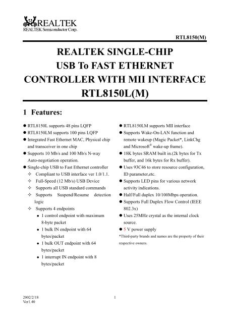
RTL8150(M)<br />
REALTEK SINGLE-CHIP<br />
USB To FAST ETHERNET<br />
CONTROLLER WITH MII INTERFACE<br />
<strong>RTL8150L</strong>(M)<br />
1 Features:<br />
� <strong>RTL8150L</strong> supports 48 pins LQFP<br />
� <strong>RTL8150L</strong>M supports 100 pins LQFP<br />
� Integrated Fast Ethernet MAC, Physical chip<br />
and transceiver in one chip<br />
� Supports 10 Mb/s and 100 Mb/s N-way<br />
Auto-negotiation operation.<br />
� Single-chip USB to Fast Ethernet controller<br />
� Compliant to USB interface ver 1.0/1.1.<br />
� Full-Speed (12 Mb/s) USB Device<br />
� Supports all USB standard commands<br />
� Supports Suspend/Resume detection<br />
logic<br />
� Supports 4 endpoints<br />
� 1 control endpoint with maximum<br />
8-byte packet<br />
� 1 bulk IN endpoint with 64<br />
bytes/packet<br />
� 1 bulk OUT endpoint with 64<br />
bytes/packet<br />
� 1 interrupt IN endpoint with 8<br />
bytes/packet<br />
� <strong>RTL8150L</strong>M supports MII interface<br />
� Supports Wake-On-LAN function and<br />
remote wakeup (Magic Packet*, LinkChg<br />
and Microsoft ® wake-up frame).<br />
� 18K bytes SRAM built in.(2k bytes for Tx<br />
buffer, and 16k bytes for Rx buffer).<br />
� Uses 93C46 to store resource configuration,<br />
ID parameter,etc.<br />
� Supports LED pins for various network<br />
activity indications.<br />
� Half/Full duplex 10/100Mbps operation.<br />
� Supports Full Duplex Flow Control (IEEE<br />
802.3x)<br />
� Uses 25MHz crystal as the internal clock<br />
source.<br />
� 5 V power supply<br />
*Third-party brands and names are the property of their<br />
respective owners.
2 General Description<br />
2002/2/18<br />
Ver1.40<br />
2<br />
RTL8150(M)<br />
The <strong>RTL8150L</strong> controller is a 48-pin LQFP single chip that supports USB to 10/100Mbps Fast<br />
Ethernet function. To connect to Home PNA 1.0 PHY or HomePNA 2.0 PHY, the 100-pin<br />
<strong>RTL8150L</strong>M provides MII interface supporting the MII transmit clock from 0.1 MHz to 25 MHz.<br />
The Realtek <strong>RTL8150L</strong>(M) is a highly integrated and cost-effective single-chip Fast Ethernet<br />
controller that provides USB to Fast Ethernet capability, and full compliance with IEEE 802.3u<br />
100Base-T specifications and IEEE 802.3x Full Duplex Flow Control. It also supports power<br />
management for modern operating systems that is capable of Operating System Directed Power<br />
Management (OSPM) to achieve the most efficient power management. Besides the PM feature,<br />
the <strong>RTL8150L</strong>(M) also supports remote wake-up (including AMD Magic Packet*, LinkChg, and<br />
Microsoft ® wake-up frame).<br />
For sake of cost-effective, the <strong>RTL8150L</strong>(M) only requires one 25MHz crystal as its internal clock<br />
source, and requires no “glue” logic or external memory.<br />
The <strong>RTL8150L</strong>(M) keeps network maintenance cost low and eliminates usage barriers. It is the<br />
easiest way to connect a PC to the computer network without opening the cover, adding cards,<br />
reconfiguring software, or any of the other technicalities.
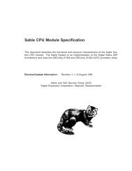
3 Pin Assignment<br />
37.VDD5<br />
38.DM<br />
39.DP<br />
40.VDD33I<br />
41.GND<br />
42.EEDO<br />
43.EEDI<br />
44.EESK<br />
45.EECS<br />
46.GND<br />
47.VDD33O<br />
48.VDD5<br />
2002/2/18<br />
Ver1.40<br />
36.VDD33<br />
1. NC<br />
35.GND<br />
2. NC<br />
34.VDD33I<br />
3. NC<br />
33.GND<br />
4. NC<br />
32.GEP0<br />
<strong>RTL8150L</strong><br />
5. TEST1<br />
31.GEP1<br />
6. TEST0<br />
3<br />
30.LED0<br />
7. XIN<br />
29.LED1<br />
8. XOUT<br />
28.LED2<br />
9. VDD33I<br />
27.VDD5<br />
10.GND<br />
26.GND<br />
11.GND<br />
25.VDD3O<br />
12.VDD33O<br />
RTL8150(M)<br />
24.VDD33I<br />
23.TXOP<br />
22.TXON<br />
21.GND<br />
20.VDD33I<br />
19. RXIP<br />
18.RXIN<br />
17.GND<br />
16.RTSET<br />
15.RTT2<br />
14.RTT3<br />
13.VDD5
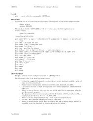
63 LED0<br />
64 GEP1<br />
65 GEP0<br />
66 MLINK<br />
67 MACTIVE<br />
68 PWRSET<br />
69 MIICOL<br />
70 GND<br />
71 NC<br />
72 VDD33I<br />
73 GND<br />
74 NC<br />
75 NC<br />
76 VDD33<br />
77 NC<br />
78 VDD5<br />
79 DM<br />
80 DP<br />
81 VDD33I<br />
82 GND<br />
83 T_TXC100<br />
84 T_RXC100<br />
85 T_VMO<br />
86 T_VPO<br />
87 T_OEB<br />
88 EEDO<br />
89 EEDI<br />
90 EESK<br />
91 EECS<br />
92 TXD3<br />
93 T_CLKIN<br />
94 T_POR<br />
95 T_RCV<br />
96 T_VM<br />
97 T_VP<br />
98 GND<br />
99 VDD33O<br />
100 NC<br />
1 NC<br />
2 NC<br />
3 NC<br />
4 VDD5<br />
5 TXD2<br />
6 TXD1<br />
7 TXD0<br />
8 TXEN<br />
9 TXC<br />
10 RXER<br />
11 RXC<br />
12 RXDV<br />
13 RXD0<br />
2002/2/18<br />
Ver1.40<br />
<strong>RTL8150L</strong>M<br />
4<br />
RTL8150(M)<br />
62 LED1<br />
61 LED2<br />
60 T_RXC<br />
59 T_TXC<br />
58 T_CK25<br />
57 T_DBG24<br />
56 MDIO<br />
55 MDC<br />
54 VDD5<br />
53 GND<br />
52 NC<br />
51 VDD33O<br />
50 NC<br />
49 NC<br />
48 NC<br />
47 NC<br />
46 VDD33I<br />
45 TXOP<br />
44 TXON<br />
43 GND<br />
42 NC<br />
41 NC<br />
40 NC<br />
39 NC<br />
38 VDD33I<br />
37 RXIP<br />
36 RXIN<br />
35 GND<br />
34 RTSET<br />
33 RTT2<br />
32 RTT3<br />
31 VDD5<br />
30 NC<br />
29 NC<br />
28 NC<br />
27 NC<br />
26 VDD33O<br />
25 NC<br />
24 GND<br />
23 GND<br />
22 NC<br />
21 VDD33I<br />
20 XOUT<br />
19 XIN<br />
18 TEST0<br />
17 TEST1<br />
16 RXD3<br />
15 RXD2<br />
14 RXD1
4 Pin Descriptions<br />
4.1 <strong>RTL8150L</strong> Pin Descriptions<br />
4.1.1 POWER PINS<br />
Symbol Type Pin No Description<br />
VDD5 P 13,27,37,48 5.0V power supply as internal regulators input<br />
VDD33O P 12,25,47 3.3V power output from internal regulators<br />
Pin 47: Digital power<br />
VDD33I P 9,20,24,34,40 3.3V power<br />
GND P<br />
Pin 40: Digital power<br />
10,11,17,21,26,33,35, Ground<br />
41,46<br />
VDD33 P 36 3.3V Standby power<br />
4.1.2 USB INTERFACE<br />
Symbol Type Pin No Description<br />
DM I/O 38 Negative data line of USB differential data bus<br />
DP I/O 39 Positive data line of USB differential data bus<br />
4.1.3 10/100 BASE-T UTP INTERFACE<br />
Symbol Type Pin No Description<br />
TXD+ O 23 10/100 BASE-T transmit data<br />
TXD- O 22 10/100 BASE-T transmit data<br />
RXIN+ I 19 10/100 BASE-T receive data<br />
RXIN- I 18 10/100 BASE-T receive data<br />
X1 I 7 25 MHz crystal input<br />
X2 O 8 25 MHz crystal output<br />
4.1.4 LED Interface<br />
Symbol Type Pin No Description<br />
LED0, 1, 2 O 30,29,28 LED pins(active low)<br />
2002/2/18<br />
Ver1.40<br />
5<br />
RTL8150(M)<br />
LEDS1-0 00 01 10 11<br />
LED0 TX/RX TX/RX TX TX/RX@ LINK10<br />
LED1 LINK100 LINK10/100 LINK10/100 TX/RX@ LINK100<br />
LED2 LINK10 FULL RX FULL<br />
During power down mode, the LED‘s are OFF if SYSLED in<br />
configuration register 1 is set.
4.1.5 EEPROM INTERFACE<br />
Symbol Type Pin No Description<br />
EECS O 45 93C46 chip select<br />
EESK O 44 93C46 clock<br />
EEDI O 43 93C46 data input<br />
EEDO I 42 93C46 data output<br />
4.1.6 TEST AND THE OTHER PINS<br />
Symbol Type Pin No Description<br />
RTT2-3 TEST 15,14 Chip test pins.<br />
TEST0-1 TEST 6,5 Chip test pins.<br />
RTSET I/O 16 This pin must be pulled low by a 1.69KΩ resistor.<br />
GEP0-1 I/O 32,31 General purpose pin 0,1<br />
NC 1,2,3,4 Reserved<br />
4.2 <strong>RTL8150L</strong>M Pin Descriptions<br />
4.2.1 <strong>RTL8150L</strong>M POWER PINS<br />
Symbol Type Pin No Description<br />
VDD5 P 4,31,54,78 5.0V power supply as internal regulators input<br />
VDD33O P 26,51,99 3.3V power output from internal regulators<br />
Pin 99: Digital power<br />
VDD33I P 21,38,46,72,81 3.3V power<br />
GND P<br />
Pin 81: Digital power<br />
23,24,35,43,53,70,73, Ground<br />
82,98<br />
VDD33 P 76 3.3V Standby power<br />
4.2.2 <strong>RTL8150L</strong>M USB INTERFACE<br />
Symbol Type Pin No Description<br />
DM I/O 79 Negative data line of USB differential data bus<br />
DP I/O 80 Positive data line of USB differential data bus<br />
4.2.3 <strong>RTL8150L</strong>M 10/100 BASE-T UTP INTERFACE<br />
Symbol Type Pin No Description<br />
TXD+ O 45 10/100 BASE-T transmit data<br />
TXD- O 44 10/100 BASE-T transmit data<br />
2002/2/18<br />
Ver1.40<br />
6<br />
RTL8150(M)
RXIN+ I 37 10/100 BASE-T receive data<br />
RXIN- I 36 10/100 BASE-T receive data<br />
X1 I 19 25 MHz crystal input<br />
X2 O 20 25 MHz crystal output<br />
4.2.4 <strong>RTL8150L</strong>M MII INTERFACE<br />
2002/2/18<br />
Ver1.40<br />
7<br />
RTL8150(M)<br />
Symbol Type Pin No Description<br />
RXD0-3 I 13,14,15,16 MII receive data 0-3<br />
TXD0-3 O 7,6,5,92 MII transmit data 0-3<br />
TXC I 9 MII Transmit Clock: 25 MHz or 2.5 MHz Tx clock supplied by<br />
the external PMD device.<br />
MIICOL I 69 MII Collision Detected: This signal is asserted high<br />
synchronously by the external physical unit upon detection of a<br />
collision on the medium. It will remain asserted as long as the<br />
collision condition persists.<br />
TXEN O 8 MII Transmit Enable: Indicates the presence of valid nibble data<br />
on TXD[3:0].<br />
RXC I 11 MII Receive Clock: 25 MHz or 2.5 MHz Rx clock supplied by the<br />
external PMD device.<br />
RXDV I 12 MII Receive Data Valid: Data valid is asserted by an external<br />
PHY when receive data is present on the RXD[3:0], and it is<br />
de-asserted at the end of the packet. This signal is valid on the<br />
rising edge of the RXC.<br />
RXER I 10 MII Receive Error: This pin is asserted to indicate that invalid<br />
symbol has been detected in 100Mbps MII mode. This signal is<br />
synchronized to RXC and can be asserted for a minimum of one<br />
receive clock.<br />
MDC O 55 MII Management Data Clock: Synchronous clock for MDIO data<br />
transfer.<br />
MDIO I/O 56 MII Management Data: Bi-directional signal used to transfer<br />
management information.<br />
Mlink I 66 MII link status notification, indicates to the MAC that external<br />
PMD is link Ok or not.<br />
Mactiveb I 67 MII active status notification, when Mactiveb=high, Mlink is low<br />
active, and vice versa.<br />
4.2.5 <strong>RTL8150L</strong>M LED Interface<br />
Symbol Type Pin No Description<br />
LED0, 1, 2 O 63,62,61 LED pins(active low)<br />
LEDS1-0 00 01 10 11<br />
LED0 TX/RX TX/RX TX TX/RX@ LINK10<br />
LED1 LINK100 LINK10/100 LINK10/100 TX/RX@ LINK100<br />
LED2 LINK10 FULL RX FULL<br />
During power down mode, the LED‘s are OFF if SYSLED in<br />
configuration register 0 is set.
4.2.6 <strong>RTL8150L</strong>M EEPROM INTERFACE<br />
Symbol Type Pin No Description<br />
EECS O 91 93C46 chip select<br />
EESK O 90 93C46 clock<br />
EEDI O 89 93C46 data input<br />
EEDO I 88 93C46 data output<br />
4.2.7 <strong>RTL8150L</strong>M TEST AND THE OTHER PINS<br />
Symbol Type Pin No Description<br />
RTT2-3 TEST 33,32<br />
17,18,57,58,59,60,83,<br />
Chip test pins.<br />
T_*** TEST 84,85,86,87,93,94,95,<br />
96,97<br />
Chip test pins.<br />
RTSET I/O 34 This pin must be pulled low by a 1.69KΩ resistor.<br />
GEP0-1 I/O 65,64 General purpose pin 0,1<br />
PWRESETB O 68<br />
1,2,3,22,25,27,28,29,<br />
Power-on reset for external PHY, active low<br />
NC<br />
30,39,40,41,42,47,48,<br />
49,50,52,71,74,75,77,<br />
100<br />
Reserved<br />
2002/2/18<br />
Ver1.40<br />
8<br />
RTL8150(M)
5. SIE –USB Commands<br />
5.1 Vender Memory Read<br />
2002/2/18<br />
Ver1.40<br />
9<br />
RTL8150(M)<br />
Setup transaction:<br />
BmReq bReq wValueL wValueH wIndexL wIndexH wLengthL wLengthH<br />
C0 05 regoffsetL regoffsetH 00 00 LengL LengH<br />
Data transaction:<br />
DATA0 DATA1 DATA2 DATA3 DATA4 DATA5 DATA6 DATA7<br />
reg0 reg1 reg2 reg3 reg4 reg5 reg6 reg7<br />
The total length response by 8150L depends on (LengH,LengL) values.<br />
5.2 Vender Memory Write<br />
Setup transaction:<br />
BmReq bReq wValueL wValueH wIndexL wIndexH wLengthL wLengthH<br />
40 05 regoffsetL regoffsetH 00 00 LenghL LenghH<br />
Data transaction:<br />
DATA0 DATA1 DATA2 DATA3 DATA4 DATA5 DATA6 DATA7<br />
reg0 reg1 reg2 reg3 reg4 reg5 reg6 reg7<br />
Offset 0x1200 to 0x127f register must write by word mode.<br />
5.3 Set address<br />
Setup transaction:<br />
BmReq bReq wValueL wValueH wIndexL wIndexH wLengthL wLengthH<br />
00 05 addrL addrH 00 00 00 00<br />
Data transaction: None<br />
5.4 Clear Feature EP0<br />
Setup transaction:<br />
BmReq bReq wValueL wValueH wIndexL wIndexH wLengthL wLengthH<br />
02 01 00 00 00 00 00 00<br />
Data transaction: None
5.5 Clear Feature EP1<br />
2002/2/18<br />
Ver1.40<br />
10<br />
RTL8150(M)<br />
Setup transaction:<br />
BmReq breq wValueL wValueH wIndexL wIndexH wLengthL wLengthH<br />
02 01 00 00 81 00 00 00<br />
Data transaction: None<br />
5.6 Clear Feature EP2<br />
Setup transaction:<br />
BmReq bReq wValueL wValueH wIndexL wIndexH wLengthL wLengthH<br />
02 01 00 00 02 00 00 00<br />
Data transaction: None<br />
5.7 Clear Feature EP3<br />
Setup transaction:<br />
BmReq bReq wValueL wValueH wIndexL wIndexH wLengthL wLengthH<br />
02 01 00 00 83 00 00 00<br />
Data transaction: None<br />
5.8 Set Feature EP1<br />
Setup transaction:<br />
BmReq bReq wValueL wValueH wIndexL wIndexH wLengthL wLengthH<br />
02 03 00 00 81 00 00 00<br />
Data transaction: None<br />
5.9 Set Feature EP2<br />
Setup transaction:<br />
BmReq bReq wValueL wValueH wIndexL wIndexH wLengthL wLengthH<br />
02 03 00 00 02 00 00 00<br />
Data transaction: None<br />
5.10 Set Feature EP3<br />
Setup transaction:
2002/2/18<br />
Ver1.40<br />
11<br />
RTL8150(M)<br />
BmReq bReq wValueL wValueH wIndexL wIndexH wLengthL wLengthH<br />
02 03 00 00 00 83 00 00<br />
Data transaction: None<br />
5.11 Set Interface 0<br />
Setup transaction:<br />
BmReq bReq wValueL wValueH wIndexL wIndexH wLengthL wLengthH<br />
01 0B 00 00 00 00 00 00<br />
Data transaction: None<br />
5.12 Set Feature Device<br />
Setup transaction:<br />
BmReq bReq wValueL wValueH wIndexL wIndexH wLengthL wLengthH<br />
00 03 01 00 00 00 00 00<br />
Data transaction: None<br />
5.13 Clear Feature Device<br />
Setup transaction:<br />
BmReq bReq wValueL wValueH wIndexL wIndexH wLengthL wLengthH<br />
00 01 01 00 00 00 00 00<br />
Data transaction: None<br />
5.14 Set Config 0<br />
Setup transaction:<br />
BmReq bReq wValueL wValueH wIndexL wIndexH wLengthL wLengthH<br />
00 09 00 00 00 00 00 00<br />
Data transaction: None<br />
5.15 Set Config 1<br />
Setup transaction:<br />
BmReq bReq wValueL wValueH wIndexL wIndexH wLengthL wLengthH<br />
00 09 01 00 00 00 00 00<br />
Data transaction: None
5.16 Get Descriptor Device<br />
2002/2/18<br />
Ver1.40<br />
12<br />
RTL8150(M)<br />
Setup transaction:<br />
BmReq bReq wValueL wValueH wIndexL wIndexH wLengthL wLengthH<br />
80 06 00 01 00 00 Lengh_L Lengh_H<br />
Data transaction:<br />
DATA0 DATA1 DATA2 DATA3 DATA4 DATA5 DATA6 DATA7<br />
12 01 10 01 00 00 00 08<br />
DA 0B 50 81 00 01 01 02<br />
03 01 - - - - - -<br />
The total length response by 8150L depends on (LengH,LengL) values.<br />
5.17 Get Descriptor Configuration<br />
Setup transaction:<br />
BmReq bReq wValueL wValueH wIndexL wIndexH wLengthL wLengthH<br />
80 06 00 02 00 00 Lengh_L Lengh_H<br />
Data transaction:<br />
DATA0 DATA1 DATA2 DATA3 DATA4 DATA5 DATA6 DATA7<br />
09 02 27 00 01 01 00 A0<br />
50 09 04 00 00 03 FF * 00<br />
FF * 00 07 05 81 02 40 00<br />
00 07 05 02 02 40 00 00<br />
07 05 83 03 08 00 01 -<br />
The total length response by 8150L depends on (LengH,LengL) values.<br />
*The E version is 0xFF ,before E version it is 0x00.<br />
5.18 Get Descriptor String Index 0<br />
Setup transaction:<br />
BmReq bReq wValueL wValueH wIndexL wIndexH wLengthL wLengthH<br />
80 06 00 03 00 00 Lengh_L Lengh_H<br />
Data transaction:<br />
DATA0 DATA1 DATA2 DATA3 DATA4 DATA5 DATA6 DATA7<br />
04 03 04 09 - - - -<br />
The total length response by 8150L depends on (LengH,LengL) values.<br />
5.19 Get Descriptor String Index 1
2002/2/18<br />
Ver1.40<br />
13<br />
RTL8150(M)<br />
Setup transaction:<br />
BmReq bReq wValueL wValueH wIndexL wIndexH wLengthL wLengthH<br />
80 06 01 03 09 04 Lengh_L Lengh_H<br />
Data transaction:(REALTEK)<br />
DATA0 DATA1 DATA2 DATA3 DATA4 DATA5 DATA6 DATA7<br />
10 03 52 00 45 00 41 00<br />
4C 00 54 00 45 00 4B 00<br />
The total length response by 8150L depends on (LengH,LengL) values.<br />
5.20 Get Descriptor String Index 2<br />
Setup transaction:<br />
BmReq bReq wValueL wValueH wIndexL wIndexH wLengthL wLengthH<br />
80 06 02 03 09 04 Lengh_L Lengh_H<br />
Data transaction:(USB 10/100 LAN)<br />
DATA0 DATA1 DATA2 DATA3 DATA4 DATA5 DATA6 DATA7<br />
1E 03 55 00 53 00 42 00<br />
20 00 31 00 30 00 2F 00<br />
31 00 30 00 30 00 20 00<br />
4C 00 41 00 4E 00 - -<br />
5.21 Get Descriptor String Index 3<br />
Setup transaction:<br />
BmReq bReq wValueL wValueH wIndexL WindexH wLengthL wLengthH<br />
80 06 03 03 09 04 Lengh_L Lengh_H<br />
Data transaction:<br />
DATA0 DATA1 DATA2 DATA3 DATA4 DATA5 DATA6 DATA7<br />
0A 03 30 00 30 00 30 00<br />
31 00 - - - - - -<br />
The total length response by 8150L depends on (LengH,LengL) values.<br />
5.22 Get Config<br />
Setup transaction:<br />
BmReq bReq wValueL wValueH wIndexL wIndexH wLengthL wLengthH<br />
80 08 00 00 00 00 01 00<br />
Data transaction:<br />
DATA0 DATA1 DATA2 DATA3 DATA4 DATA5 DATA6 DATA7<br />
Value - - - - - - -
5.23 Get Status Device<br />
2002/2/18<br />
Ver1.40<br />
14<br />
RTL8150(M)<br />
Setup transaction:<br />
BmReq bReq wValueL wValueH wIndexL wIndexH wLengthL wLengthH<br />
80 00 00 00 00 00 02 00<br />
Data transaction:<br />
DATA0 DATA1 DATA2 DATA3 DATA4 DATA5 DATA6 DATA7<br />
Value Value - - - - - -<br />
5.24 Get Status EP0<br />
Setup transaction:<br />
BmReq bReq wValueL wValueH wIndexL wIndexH wLengthL wLengthH<br />
82 00 00 00 00 00 02 00<br />
Data transaction:<br />
DATA0 DATA1 DATA2 DATA3 DATA4 DATA5 DATA6 DATA7<br />
Value Value - - - - - -<br />
5.25 Get Status EP1<br />
Setup transaction:<br />
BmReq bReq wValueL wValueH wIndexL wIndexH wLengthL wLengthH<br />
82 00 00 00 81 00 02 00<br />
Data transaction:<br />
DATA0 DATA1 DATA2 DATA3 DATA4 DATA5 DATA6 DATA7<br />
Value value - - - - - -<br />
5.26 Get Status EP2<br />
Setup transaction:<br />
BmReq bReq wValueL wValueH wIndexL wIndexH wLengthL wLengthH<br />
82 00 00 00 02 00 02 00<br />
Data transaction:<br />
DATA0 DATA1 DATA2 DATA3 DATA4 DATA5 DATA6 DATA7<br />
Value value - - - - - -<br />
5.27 Get Status EP3
2002/2/18<br />
Ver1.40<br />
15<br />
RTL8150(M)<br />
Setup transaction:<br />
BmReq bReq wValueL wValueH wIndexL wIndexH wLengthL wLengthH<br />
82 00 00 00 83 00 02 00<br />
Data transaction:<br />
DATA0 DATA1 DATA2 DATA3 DATA4 DATA5 DATA6 DATA7<br />
Value Value - - - - - -<br />
5.28 Get Status Interface 0<br />
Setup transaction:<br />
BmReq bReq wValueL wValueH wIndexL wIndexH wLengthL wLengthH<br />
81 00 00 00 00 00 02 00<br />
Data transaction:<br />
DATA0 DATA1 DATA2 DATA3 DATA4 DATA5 DATA6 DATA7<br />
Value value - - - - - -<br />
5.29 Get Interface 0<br />
Setup transaction:<br />
BmReq bReq wValueL wValueH wIndexL wIndexH wLengthL wLengthH<br />
81 0A 00 00 00 00 01 00<br />
Data transaction:<br />
DATA0 DATA1 DATA2 DATA3 DATA4 DATA5 DATA6 DATA7<br />
value - - - - - - -
6. Memory Allocation<br />
2002/2/18<br />
Ver1.40<br />
$0000H~$011FH------- Reserved<br />
$0120H~$01FFH------- <strong>RTL8150L</strong>(M) REGISTER<br />
$1200H~$127FH--------Serial EEPROM(9346)<br />
Offset Type Pin No Description<br />
0120h-0125h R/W* IDR0-5 Ethernet Address ,load from 93C46<br />
0126h-012Dh R/W MAR0-7 Multicast register<br />
012Eh R/W CR Command Register<br />
012Fh R/W TCR Transmit configuration register<br />
0130-0131h R/W RCR Receive configuration register<br />
0132h R/W TSR Transmit status register<br />
0133h R/W RSR Receive status register<br />
0134h R/W Reserved -<br />
0135h R/W* CON0 Configuration register0<br />
0136h R/W* CON1 Configuration register1<br />
0137h R/W MSR Medium status<br />
0138h R/W PHYADD MII PHY address select<br />
0139-013Ah R/W PHYDAT MII PHY data<br />
013Bh R/W PHYCNT MII PHY control<br />
013Ch R/W Reserved<br />
013Dh R/W* GPPC General purpose pin control<br />
013Eh R/W WAKECNT Wake up event control<br />
0140h-0141h R/W* BMCR Basic mode control register<br />
0142h-0143h R BMSR Basic mode status register<br />
0144h-0145h R/W* ANAR Auto-negotiation advertisement register<br />
0146h-0147h R/W ANLP Auto-negotiation link partner ability register<br />
0148h-0149h R/W AER Auto-negotiation expansion register<br />
014Ah-014Bh R/W NWAYT Nway test register<br />
014Ch-014Dh R/W CSCR CS confiiguration register<br />
014Eh-014Fh R/W CRC0 Power Management CRC register for wakeup frame0<br />
0150h-0151h R/W CRC1 Power Management CRC register for wakeup frame1<br />
0152h-0153h R/W CRC2 Power Management CRC register for wakeup frame2<br />
0154h-0155h R/W CRC3 Power Management CRC register for wakeup frame3<br />
0156h-0157h R/W CRC4 Power Management CRC register for wakeup frame4<br />
0158h-015Fh R/W BYEMASK0 Power Management wakeup frame0(64bit) bytemask<br />
0160h-0167h R/W BYEMASK 1 Power Management wakeup frame1(64bit) bytemask<br />
0168h-016Fh R/W BYEMASK 2 Power Management wakeup frame2(64bit) bytemask<br />
0170h-0177h R/W BYEMASK 3 Power Management wakeup frame3(64bit) bytemask<br />
0178h-017Fh R/W BYEMASK 4 Power Management wakeup frame4(64bit) bytemask<br />
0180h-0183h R/W PHY1 PHY parameter 1<br />
0184h R /W PHY2 PHY parameter 2<br />
0186h-0189h R/W TW1 Twister parameter 1<br />
018Ah-01ff Reserved<br />
* : denotes auto-loaded from 93C46 during chip initialization.<br />
16<br />
RTL8150(M)
7. Register Descriptions<br />
7.1 Command Register (Offset 012Eh, R/W)<br />
Bit Symbol Description<br />
2002/2/18<br />
Ver1.40<br />
17<br />
RTL8150(M)<br />
Default/<br />
Attribute<br />
7-6 - Reserved -<br />
5 WEPROM 1:EEPROM write enable<br />
0: disable<br />
The EEPROM map from 0x1200 to 127fh. Write 0x1200 equal to<br />
program EEPROM offset 0x00. Write to EEPROM must use WORD<br />
mode access at a time. The read EEPROM have not limit.<br />
0,R/W<br />
4 SOFT_RST Reset: Setting to 1 forces the <strong>RTL8150L</strong>(M) to a software reset state<br />
which disables the transmitter and receiver, reinitializes the FIFOs,<br />
resets the system buffer pointer to the initial value , Rx buffer is<br />
empty). The values of IDR0-5 and MAR0-7 will have no changes.<br />
This bit is 1 during the reset operation, and is cleared to 0 by the<br />
<strong>RTL8150L</strong>(M) when the reset operation is complete.<br />
0,R/W<br />
3 RE Ethernet 10/100M receive enable 0,R/W<br />
2 TE Ethernet 10/100M transmit enable 0,R/W<br />
1 EP3CLREN 1: Enable clearing the performance counter of EP3 after EP3 access.<br />
0: Disable<br />
0,R/W<br />
0 AUTOLOAD 1: Auto-load the contents of 93c46 into <strong>RTL8150L</strong>(M)’s registers.<br />
This bit is self clearing after load complete.<br />
0,R/W<br />
7.2 Transmit Configuration Register (Offset 012Fh, R/W)<br />
Bit Symbol Description Default/<br />
Attribute<br />
7-6 TXRR1, 0 Tx Retry Count: These 2 bits are used to specify additional<br />
transmission retries in multiple of 16(IEEE 802.3 CSMA/CD retry<br />
count). If the TXRR is set to 0, the transmitter will re-transmit 16<br />
times before aborting due to excessive collisions if the TXRR is set<br />
to a value greater than 0, the transmitter will re-transmit a number of<br />
times equals to the following formula before aborting:<br />
Total retries = 16 + (TXRR * 16)<br />
The ECOL bit in the TSR register will be set if transmit abort due to<br />
excessive collision.<br />
0,R/W<br />
5 Reserve -<br />
4,3 IFG1, 0 Interframe Gap Time: This field allows the user to adjust the<br />
interframe gap time below the standard: 9.6 us for 10Mbps, 960 ns<br />
for 100Mbps. The time can be programmed from 9.6 us to .8.4 us<br />
(10Mbps) and 960ns to 840ns (100Mbps).<br />
The formula for the inter frame gap is:<br />
0,R/W<br />
10 Mbps 8.4us + 0.4(IFG(1:0)) us<br />
100 Mbps 840ns + 40(IFG(1:0)) ns<br />
2, 1 Reserved - -<br />
0 NOCRC 1: There’s no CRC appended at the end of a packet.<br />
0: There’s CRC appended at the end of a packet.<br />
0,R/W
7.3 Receive Configuration Register (Offset 0130h-0131h,<br />
R/W)<br />
Bit Symbol Description<br />
RTL8150(M)<br />
Default/<br />
Attribute<br />
15-8 - Reserved -<br />
7 TAIL 0: CRC field forward to HOST<br />
1: Rx Header forward to HOST. The first two bytes of CRC field are<br />
replaced by receive header.<br />
0,R/W<br />
6 AER 1:Accept CRC error packet 0,R/W<br />
5 AR 1: Accept RUNT packet (
2002/2/18<br />
Ver1.40<br />
19<br />
RTL8150(M)<br />
5 LKCHG Link Change indication R<br />
4 RUNT Runt Packet indication<br />
1: The received packet length is smaller than 64 bytes.<br />
R<br />
3 LONG Long Packet indication<br />
1: The size of the received packet exceeds 4k bytes.<br />
R<br />
2 CRC CRC Error indication.<br />
1: The received packet is checked with CRC error.<br />
R<br />
1 FAE Frame Alignment Error:<br />
1: Indicates that a frame alignment error occurred on this received<br />
packet.<br />
R<br />
0 ROK Receive OK indication.<br />
1: Indicate that a packet is received without error.<br />
R<br />
Note: RSR register will be cleared to the default value after read or EP3 access.<br />
7.6 Configuration Register 0(Offset 0135h, R/W)<br />
Bit Symbol Description<br />
Default/<br />
Attribute<br />
7 SUSLED 0: LED pins are driven high to turn off LED during suspend. 0,R/W<br />
6 PARM_EN Parameter Enable: (These parameters are used in 100Mbps mode.)<br />
1: PHY1_PARM, PHY2_PARM, TW_PARM can be modified<br />
through access to register 0180H~0189H.<br />
0: Disable<br />
Note: Each time 93C46 auto-load process is executed, the PHY1_PARM,<br />
PHY2_PARM, TW_PARM will be re-loaded the default value from<br />
93C46.<br />
0,R/W<br />
4-5 - Reserved -<br />
3 LDPS Link Down Power Saving mode:<br />
1: Disable.<br />
0: Enable. When the ethernet cable is disconnected (Link Down),<br />
part of analog circuit will be powered down in order to save power.<br />
The other part of analog circuits relating to SD signal monitoring<br />
and 100M signal receiving are not powered down in case the cable<br />
is re-connected and link should be re-established again.<br />
0,R/W<br />
2 MSEL Medium Select<br />
When write :<br />
1:MII mode (disable internal PHY)<br />
0,R/W<br />
0:Auto-detect. The UTP mode will be the default. The<br />
1-0 LEDS1-0<br />
<strong>RTL8150L</strong>(M) is switched to MII mode if the internal PHY is not<br />
link OK.<br />
When read<br />
1:MII mode: The MAC MII is connected to the MII interface of the<br />
external PHY.<br />
0:UTP mode: The MAC MII is connected to the internal PHY.<br />
Refer to LED PIN definition. The default value is auto-loaded from<br />
93C46.<br />
0,R/W<br />
7.7 Configuration Register 1(Offset 0136h, R/W)<br />
Bit Symbol Description Default/
2002/2/18<br />
Ver1.40<br />
20<br />
RTL8150(M)<br />
Attribute<br />
7 - Reserved. -<br />
6 BWF Broadcast Wakeup Frame Function:<br />
1: Enable Broadcast Wakeup Frame<br />
0,R/W<br />
If set_feature command with Feature Selector<br />
5 MWF<br />
=DEVICE_REMOTE_WAKEUP is received from USB host and<br />
BWF=1, <strong>RTL8150L</strong>(M) will signal wakeup to the host when<br />
correctly receiving a packet with DID=FF FF FF FF FF FF<br />
(Broadcast packet),.<br />
0: Disable.<br />
Multicast Wakeup Frame Function:<br />
1: Enable Multicast Wakeup Frame<br />
0,R/W<br />
If set_feature command with Feature Selector<br />
4 UWF<br />
=DEVICE_REMOTE_WAKEUP is received from USB host and<br />
MWF=1, <strong>RTL8150L</strong>(M) will signal wakeup to the host when<br />
correctly receiving multicast packets (packets that survive the<br />
multicast hash),.<br />
0: Disable.<br />
Unicast Wakeup Frame Function:<br />
1: Enable Unicast Wakeup Frame<br />
0,R/W<br />
f set_feature command with Feature Selector<br />
2-3 -<br />
=DEVICE_REMOTE_WAKEUP is received from USB host and<br />
UWF=1, <strong>RTL8150L</strong>(M) will signal wakeup to the host when<br />
correctly receiving a packet with DID=IDR0~5.<br />
0: Disable.<br />
Reserved -<br />
1 LONGWF1 1: The Bytemask3 and Bytemask4 are cascaded to form a 128 byte<br />
long Bytemask for long wakeup frame 1, and long wakeup frame 1<br />
use CRC3 as CRC check. When LONGWF1=1, wakeup frame 3<br />
and wakeup frame 4 are disable.<br />
0: Disable LOGNWF1.<br />
0,R/W<br />
0 LONGWF0 1: The Bytemask1 and Bytemask2 are cascaded to form a 128 byte<br />
long Bytemask for long wakeup frame 0, and long wakeup frame 0<br />
use CRC1 as CRC check. When LONGWF0=1, wakeup frame 1<br />
and wakeup frame 2 are disabled.<br />
0: Disable LOGNWF0.<br />
0,R/W<br />
7.8 Media Status Register (Offset 0137h, R/W)<br />
Bit Symbol Description<br />
7 TXFCE/<br />
LdTXFCE<br />
Tx Flow Control Enable: The flow control is valid in full-duplex<br />
mode only. This register‘s default value comes from 93C46.<br />
<strong>RTL8150L</strong> Remote TXFCE/LdTXFCE<br />
ANE = 1 NWAY FLY mode R/O<br />
ANE = 1 NWAY mode only R/W<br />
ANE = 1 No NWAY R/W<br />
ANE = 0 &<br />
- R/W<br />
full-duplex mode<br />
ANE = 0 &<br />
half-duplex<br />
mode<br />
- Invalid<br />
Default/<br />
Attribute<br />
R/W
2002/2/18<br />
Ver1.40<br />
21<br />
RTL8150(M)<br />
6 RXFCE<br />
NWAY FLY mode : NWAY with flow control capability<br />
NWAY mode only : NWAY without flow control capability<br />
RX Flow control Enable: The flow control is enabled in full-duplex<br />
mode only. The default value comes from 93C46 .<br />
R/W<br />
5 Reserved - -<br />
4 Duplex 1: Indicate that the current link is full-duplex<br />
0: Indicate that the current link is half-duplex<br />
R<br />
3 SPEED_100 1: Indicate that the current link is in 100Mbps mode.<br />
R<br />
2 LINK Link status.<br />
1: Link OK.<br />
0: Indicate that the current link is in 10Mbps mode.<br />
0: Link Fail.<br />
1 TXPF 1: Indicate that <strong>RTL8150L</strong>(M) sends pause packet.<br />
0: Indicate that <strong>RTL8150L</strong>(M) has sent timer done packet to release<br />
remote station from pause Tx state.<br />
0 RXPF 1: Indicate that <strong>RTL8150L</strong>(M) is in Backoff state because a pause<br />
packet from remote station has been receipt.<br />
0: Indicate that <strong>RTL8150L</strong>(M) is not in pause state.<br />
7.9 MII PHY Address(Offset 0138h, R/W)<br />
Bit Symbol Description<br />
R<br />
R<br />
R<br />
Default/<br />
Attribute<br />
7-5 Reserved -<br />
4-0 PHYADD MII PHY Address select R/W<br />
7.10 MII PHY DATA(Offset 0139h-013Ah, R/W)<br />
Bit Symbol Description<br />
Default/<br />
Attribute<br />
15-0 MIIDAT Data read from MII PHY or data that is to be written to MII PHY. R/W<br />
7.11 MII PHY Access Control(Offset 013Bh, R/W)<br />
Bit Symbol Description<br />
Default/<br />
Attribute<br />
7 Reserved -<br />
6 PHYOWN Own bit: <strong>RTL8150L</strong>(M) will initiate a MII management data<br />
transaction if this bit is set 1 by software. After transaction,<br />
this bit is auto cleared by <strong>RTL8150L</strong>.<br />
0,R/W<br />
5 RWCR MII management data R/W control<br />
1:write,<br />
0: read<br />
R/W<br />
4-0 PHYOFF PHY register offset R/W
7.12 General Purpose Register(Offset 013Dh, R/W)<br />
Bit Symbol Description/Usage<br />
2002/2/18<br />
Ver1.40<br />
22<br />
RTL8150(M)<br />
Default/<br />
Attribute<br />
7-5 GEPREG1~3 Reserved -<br />
4 GEPREG0 General purpose bit<br />
1: Supports external Home PNA PHY<br />
RO<br />
3 GEP1DAT If GEP1RW is set 1, the GEP1 pin will reflect the value of GEP1DAT,<br />
else GEP1DAT will reflect the value of GEP1 pin.<br />
R/W<br />
2 GEP1RW General purpose pin control bit:<br />
0: The corresponding GEP1 pin is considered input<br />
1: The corresponding GEP1 pin is considered output<br />
R/W<br />
1 GEP0DAT If GEP0RW is set 1, the GEP0 pin will reflect the value of GEP0DAT,<br />
else GEP0DAT will reflect the value of GEP0 pin.<br />
R/W<br />
0 GEP0RW General purpose pin control bit:<br />
0: The corresponding GEP0 pin is considered input<br />
1: The corresponding GEP0 pin is considered output<br />
R/W<br />
If GEPRW=0 ,READ only<br />
7.13 Wake Up Event Control(Offset 013E, R/W)<br />
Bit Symbol Description/Usage<br />
Default/<br />
Attribute<br />
7 Reserved -<br />
6 LKWEN Link change wake-up enable 0, R/W<br />
5 MAGWEN Magic Packet wake-up enable 0, R/W<br />
4 WUF4EN Wake up frame 4 enable 0, R/W<br />
3 WUF3EN Wake up frame 3 enable 0, R/W<br />
2 WUF2EN Wake up frame 2 enable 0, R/W<br />
1 WUF1EN Wake up frame 1 enable 0, R/W<br />
0 WUF0EN Wake up frame 0 enable 0, R/W<br />
Note: <strong>RTL8150L</strong>(M) will signal wakeup to the host only when the following two conditions are met:<br />
1. The host has send set_feature_device command.<br />
2. One of the wakeup frame function has been enabled and triggered.<br />
7.14 Basic Mode Control Register (Offset 0140h-0141h, R/W)<br />
Bit Name Description/Usage<br />
Default/<br />
Attribute<br />
15 Reset This bit, which is self clearing, will reset the control and status<br />
registers of PHY into the default states if it is set 1.<br />
0, RW<br />
14 Reserved - -<br />
13 Spd_Set Speed select.<br />
1 = 100Mbps;<br />
0 = 10Mbps.<br />
Note: The initial value of this bit comes from 93C46<br />
RW
2002/2/18<br />
Ver1.40<br />
12 Auto Negotiation<br />
Enable<br />
(ANE)<br />
This bit enables/disables the NWay auto-negotiation function.<br />
1 = Enable auto-negotiation. If this bit is set, bit 8 and bit13 will be<br />
ignored, and the values of bit8 and bit 13 indicate the result of auto<br />
negotiation process.<br />
0 = Disable auto-negotiation.<br />
Note: The initial value of this bit comes from 93C46<br />
23<br />
RTL8150(M)<br />
0, RW<br />
11-10 Reserved - -<br />
9 Restart Auto This bit allows the NWay auto-negotiation function to be re-initiated. 0, RW<br />
Negotiation 1 = Re-start auto-negotiation<br />
0 = Normal operation.<br />
8 Duplex Mode This bit sets the duplex mode.<br />
1 = full-duplex<br />
0 = normal operation.<br />
Note: This bit‘s initial value comes from 93C46<br />
0, RW<br />
7-0 Reserved - -<br />
7.15 Basic Mode Status Register (Offset 0142h-0143h, R)<br />
Bit Name Description/Usage<br />
Default/<br />
Attribute<br />
15<br />
100Base-T4<br />
100Base-T4 Capable:<br />
0 = Device not able to perform 100Base-T4 mode<br />
0, RO<br />
14<br />
100Base-TX Full Duplex Capable:<br />
100Base_TX_ FD<br />
1 = Device able to perform 100Base-TX in full duplex mode<br />
1, RO<br />
13<br />
100Base_TX_HD<br />
100Base-TX Half Duplex Capable:<br />
1 = Device able to perform 100Base-TX in half duplex mode<br />
1, RO<br />
12<br />
10Base_T_FD<br />
10Base-T Full Duplex Capable:<br />
1 = Device able to perform 10Base-T in full duplex mode<br />
1, RO<br />
11<br />
10_Base_T_HD<br />
10Base-T Half Duplex Capable:<br />
1 = Device able to perform 10Base-T in half duplex mode<br />
1, RO<br />
10-6 - Reserved -<br />
5 Auto Negotiation 1 = Auto-negotiation process completed;<br />
0, RO<br />
Complete 0 = Auto-negotiation process not completed.<br />
4<br />
Remote Fault<br />
1 = Remote fault condition detected (clear on read);<br />
0 = No remote fault condition detected.<br />
0, RO<br />
3 Auto Negotiation 1 = Device is able to perform Auto-Negotiation.<br />
1, RO<br />
ability 0 = Device not able to perform Auto-Negotiation.<br />
2-1 Reserved<br />
0 Extended 1 = Extended register capabilities;<br />
1, RO<br />
Capability 0 = Basic register set capabilities.<br />
7.16 Auto-negotiation Advertisement Register (Offset<br />
0144h-0145h, R/W)<br />
Bit Name Description/Usage<br />
15 NP Next Page capability.<br />
0 = Advertise that NP capability not supported by local mode<br />
Default/<br />
Attribute<br />
0, RO
2002/2/18<br />
Ver1.40<br />
24<br />
RTL8150(M)<br />
14 ACK<br />
1 = Advertise NP exchange capability and desire to transfer next<br />
page.<br />
1 = Acknowledge reception of link partner’s capability data word. 0, RO<br />
13 RF 1 = Advertise remote fault detection capability;<br />
0 = Do not advertise remote fault detection capability.<br />
0, RW<br />
12-11 - Reserved -<br />
10 PAUSE 1 = Advertise flow control supported by local node.<br />
0 = Advertise flow control not supported by local mode.<br />
9 T4 1 = Advertise 100Base-T4 supported by local node;<br />
0 = Advertise 100Base-T4 not supported by local node.<br />
8 TXFD 1 = Advertise 100Base-TX full duplex supported by local node;<br />
0 = Advertise 100Base-TX full duplex not supported by local node.<br />
7 TX 1 = Advertise 100Base-TX supported by local node;<br />
0 = Advertise 100Base-TX not supported by local node.<br />
6 10FD 1 = Advertise 10Base-T full duplex supported by local node;<br />
0 = Advertise 10Base-T full duplex not supported by local node.<br />
5 10 1 = Advertise 10Base-T supported by local node;<br />
0 = Advertise 10Base-T not supported by local node.<br />
4-0 Selector Binary encoded selector supported by this node. Currently only<br />
CSMA/ CD is specified. No other protocols are supported.<br />
7.17 Auto-Negotiation Link Partner Ability Register<br />
(Offset 0146h-0147h, R)<br />
Bit Name Description/Usage<br />
15 NP Next Page Indication:<br />
0 = Link Partner does not desire Next Page Transfer<br />
1 = Link Partner desires Next Page Transfer.<br />
14 ACK 1 = link partner acknowledges reception of the capability data word.<br />
0 = Not acknowledged<br />
The device’s Auto-Negotiation state machine will automatically<br />
control this bit based on the incoming FLP bursts.<br />
The default<br />
value comes<br />
from<br />
EEPROM, RO<br />
0, RO<br />
1, RW<br />
1, RW<br />
1, RW<br />
1, RW<br />
,<br />
RW<br />
Default/<br />
Attribute<br />
0, RO<br />
0, RO<br />
13 RF Remote Fault:<br />
1 = Remote Fault indicated by Link Partner<br />
0 = No Remote Fault indicated by Link Partner.<br />
0, RO<br />
12-11 Reserved - -<br />
10 Pause 1 = Flow control is supported by link partner ,<br />
0, RO<br />
0 = Flow control is not supported by link partner.<br />
9 T4 100BASE-T4 Support:<br />
1 = 100Base-T4 is supported by the link partner;<br />
0 = 100Base-T4 not supported by the link partner.<br />
8 TXFD 100BASE-TX Full Duplex Support:<br />
1 = 100Base-TX full duplex is supported by the link partner;<br />
0 = 100Base-TX full duplex not supported by the link partner.<br />
7 TX 100BASE-TX Support:<br />
1 = 100Base-TX is supported by the link partner;<br />
0 = 100Base-TX not supported by the link partner.<br />
6 10FD 10BASE-T Full Duplex Support:<br />
1 = 10Base-T full duplex is supported by the link partner;<br />
0, RO<br />
0, RO<br />
0, RO<br />
0, RO
0 = 10Base-T full duplex not supported by the link partner.<br />
5 10 10BASE-T Support:<br />
1 = 10Base-T is supported by the link partner;<br />
0 = 10Base-T not supported by the link partner.<br />
4-0 Selector Protocol Selection Bits:<br />
Link Partner’s binary encoded protocol selector.<br />
7.18 Auto-negotiation Expansion Register (Offset<br />
0148h-0149h, R)<br />
This register contains additional status for NWay auto-negotiation.<br />
Bit Name Description/Usage<br />
RTL8150(M)<br />
0, RO<br />
0, RO<br />
Default/<br />
Attribute<br />
15-5 - Reserved, This bit is always set to 0. -<br />
4 MLF Status indicating if a multiple link fault has occurred.<br />
1 = fault occurred; 0 = no fault occurred.<br />
0, RO<br />
3 LP_NP_ABLE Status indicating if the link partner supports Next Page negotiation. 1<br />
= supported; 0 = not supported.<br />
0, RO<br />
2 NP_ABLE This bit indicates if the local node is able to send additional Next<br />
Pages.<br />
0, RO<br />
1 PAGE_RX This bit is set when a new Link Code Word Page has been received.<br />
The bit is automatically cleared when the auto-negotiation link<br />
partner‘s ability register (register 146h) is read by management.<br />
0, RO<br />
0 LP_NW_ABLE 1 = link partner supports NWay auto-negotiation. 0, RO<br />
7.19 NWay Test Register (Offset 014Ah-014Bh, R/W)<br />
Bit Name Description/Usage<br />
Default/<br />
Attribute<br />
15-8 - Reserved -<br />
7 NWLPBK 1 = set NWay to loopback mode. 0, RW<br />
6-4 - Reserved -<br />
3 ENNWLE 1 = LED0 Pin indicates linkpulse 0, RW<br />
2 FLAGABD 1 = Auto-neg experienced ability detect state 0, RO<br />
1 FLAGPDF 1 = Auto-neg experienced parallel detection fault state 0, RO<br />
0 FLAGLSC 1 = Auto-neg experienced link status check state 0, RO<br />
7.20 CS Configuration Register (Offset 014Ch-014Dh, R/W)<br />
Bit Name Description/Usage<br />
Default/<br />
Attribute<br />
15 Testfun 1 = Speeds up internal timer for Auto-Negociation 0,WO<br />
14-10 - Reserved -<br />
9 LD Active low TPI link disable signal. When low, TPI still transmits link<br />
pulses and TPI stays in good link state.<br />
1, RW<br />
8 HEART BEAT 1 = HEART BEAT enable 1, RW<br />
2002/2/18<br />
Ver1.40<br />
25
2002/2/18<br />
Ver1.40<br />
0 = HEART BEAT disable. HEART BEAT function is only valid in<br />
10Mbps mode.<br />
7 JBEN 1 = enable jabber function.<br />
0 = disable jabber function<br />
26<br />
RTL8150(M)<br />
1, RW<br />
6 F_LINK_100 Force link-up in 100Mbps for diagnostic purposes.<br />
1 = DISABLE<br />
0 = ENABLE.<br />
1, RW<br />
5 F_Connect Force connection of the link for diagnostic purposes:<br />
1 = Fore connection<br />
0 = Disable<br />
0, RW<br />
4 - Reserved -<br />
3 Con_status This bit indicates the status of the connection.<br />
1 = valid connected link detected<br />
0 = disconnected link detected.<br />
0, RO<br />
2 Con_status_En Assertion of this bit configures LED1 pin to indicate connection<br />
status.<br />
0, RW<br />
1 - Reserved -<br />
0 PASS_SCR Bypass Scramble function 0, RW<br />
8 EEPROM 93C46 Contents<br />
The 93C46 is a 1K-bit EEPROM. Although it is actually addressed by words, we list its contents by<br />
bytes below for convenience.<br />
After the valid duration of the RSTB pin or auto-load command in Command Register(offset<br />
012Eh), the <strong>RTL8150L</strong>(M) performs a series of EEPROM read operation from the 93C46.<br />
� If you want to change the Realtek default setting of the content in EEPROM, we suggest that<br />
you have Realtek approval.<br />
Bytes Contents Description<br />
00h 50h<br />
01h 81h<br />
These 2 bytes contain ID code word for the <strong>RTL8150L</strong>(M). The <strong>RTL8150L</strong>(M)<br />
will load the contents of EEPROM into the corresponding location if the ID<br />
word (8150h) is right.<br />
02h-07h Ethernet ID Ethernet ID, After auto-load command or hardware reset, <strong>RTL8150L</strong>(M) loads<br />
Ethernet ID to IDR0-IDR5 of <strong>RTL8150L</strong>(M)'s.<br />
08h CONFIG0 <strong>RTL8150L</strong>(M) Configuration register 0, operational registers offset 0135h.<br />
09h MSR/BMCR Bit7-6 map to the bit7-6 of Media Status register (MSR), Bit5, 4, 0 map to the<br />
bit13, 12, 8 of Basic Mode Control register (BMCR), Bit2 maps to the bit10 of<br />
Auto-negotiation Advertisement Register (ANAR), Bit3, 1 are reserved. If the<br />
network speed is set to Auto-Detect mode (i.e. Nway mode), then Bit2=0 means<br />
the local <strong>RTL8150L</strong>(M) supports flow control (IEEE 802.3x) (in this case,<br />
Bit10=1 in Auto-negotiation Advertisement Register (offset 146h-147h), and<br />
Bit2=1 means the local <strong>RTL8150L</strong>(M) does not support flow control (in this<br />
case, Bit10=0 in Auto-negotiation Advertisement). This is because that there<br />
are Nway switch hubs will keep sending flow control pause packets with no<br />
reason, if the link partner supports Nway flow control.<br />
0Ah GEP General Purpose Pin Control Register (offset 013Dh).<br />
0Bh UDP Reserved. Do not change this filed without Realtek approval.<br />
USB Device Parameter<br />
0Ch ATTR USB Configuration characteristics:
2002/2/18<br />
Ver1.40<br />
27<br />
RTL8150(M)<br />
0Dh PHY2_PARM<br />
Bit7 is reserved and must be set to one for USB spec.<br />
A device configuration that uses power from the bus and a local source reports<br />
a non-zero value in MaxPower to indicate the amount of bus power required<br />
and sets Bit 6.<br />
Bit5 is set one to support remote wakeup.<br />
Bit4-0: Reserved and must be reset to zero for USB spec.<br />
Reserved. Do not change this filed without Realtek approval.<br />
PHY Parameter 2 for <strong>RTL8150L</strong>(M). Operational register of the <strong>RTL8150L</strong>(M)<br />
is 0184h.<br />
0Eh-11h PHY1_PARM Reserved. Do not change this filed without Realtek approval.<br />
PHY Parameter 1 for <strong>RTL8150L</strong>(M). Operational register of the <strong>RTL8150L</strong>(M)<br />
is 0180h-0183h.<br />
12h-15h TW1_PARM Reserved. Do not change this filed without Realtek approval.<br />
Twister Parameter for <strong>RTL8150L</strong>(M). Operational registers of the<br />
16h MAXPOR<br />
<strong>RTL8150L</strong>(M) are 0186h-0189h.<br />
The maximum USB power consumption.<br />
17h INTERVAL Interval for pollin endpoint 3 for data transfers. Expressed in milliseconds.<br />
18h-19h LanguageID The string in a USB device may support multiple languages. A manufacturer<br />
can specify the desired language using a sixteen-bit language ID.<br />
1Ah-1Bh ManufacturerID The system manufacturer’s ID.<br />
1Ch-1Dh ProductID The of a system manufacturer’s product ID.<br />
1Eh-27h Serial number The product’s serial number.<br />
28h-4fh Manufacturer These bytes specify a manufacturer’s information for the USB standard request.<br />
String Maximum string length is 40 bytes.<br />
50h-7dh Product String These bytes specify a device’s information for the USB standard request.<br />
Maximum string length is 46 bytes.<br />
7eh-7fh Reserved<br />
8.1 Summary of <strong>RTL8150L</strong>‘s registers in the<br />
EEPROM(93C46)<br />
Offset Name Type Bit7 Bit6 Bit5 Bit4 Bit3 Bit2 Bit1 Bit0<br />
00h ROMID0 R 0 1 0 1 0 0 0 0<br />
01h ROMID1 R 1 0 0 0 0 0 0 1<br />
02-07h IDR0-IDR5 R/W<br />
08h Config0 R/W SUSLED PARM_EN - - LDPS MSEL LEDS1 LEDS0<br />
09h MSR/ BMCR R/W TXFCE RXFCE Spd_set ANE - PAUSE - FUDUP<br />
0Ah GPCP R/W GEPREG3 GEPREG2 GEPREG1 GEPREG0 GEP1DAT GEP1RW GEP0DAT GEP0RW<br />
0Bh UDP R/W 8 bit Read Write<br />
0Ch ATTR R/W 1 0 1 0 0 0 0 0<br />
0Dh PHY2_PARM R/W 8 bit Read Write<br />
0E-11h PHY1_PARM R/W 32 bit Read Write<br />
12h-15h TW1_PARM R/W 32 bit Read Write<br />
16h MAXPOR R/W 8 bit Read Write<br />
17h Interval R/W 0 0 0 0 0 0 0 1<br />
18h-19h Language ID R/W 16 bit Read Write<br />
1Ah-1Bh Manufacture<br />
ID<br />
R/W 16 bit Read Write<br />
1Ch-1Dh Product ID R/W 16 bit Read Write<br />
1Eh-27h Serial number R/W 10 bytes Read Write
28h-4fh Manufacture<br />
String<br />
R/W 40 bytes Read Write<br />
50h-7dh Product string R/W 46 bytes Read Write<br />
7eh-7fh Reserved - -<br />
2002/2/18<br />
Ver1.40<br />
28<br />
RTL8150(M)
9 Functional Description<br />
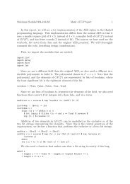
9.1 System Block Diagram<br />
DP<br />
DM<br />
9.2 USB Endpoint SIE function description<br />
2002/2/18<br />
Ver1.40<br />
SIE<br />
29<br />
RTL8150(M)<br />
The SIE employs a robust hardwired USB protocol implementation so that the entire USB<br />
interface operation could be done without firmware intervention. For all three types of EP’s, bulk<br />
in,bulk out, and interrupt, appropriate responses and handshake signals are generated by SIE.<br />
The SIE analog transceiver complies fully with driver and receiver characteristics defined in<br />
USB Spec. Rev. 1.1,<br />
9.2.1 Endpoint0<br />
EEPROM<br />
Interface<br />
Memory<br />
Management<br />
Unit<br />
(MMU)<br />
SRAM<br />
Tx/2k bytes<br />
Rx/16k bytes<br />
MAC<br />
Controller<br />
10/100Mbps<br />
PHY<br />
MII<br />
Interface<br />
TXO+<br />
TXO-<br />
RXIN+<br />
RXIN-<br />
All USB devices support a common accesses mechanism for accessing information through this
2002/2/18<br />
Ver1.40<br />
30<br />
RTL8150(M)<br />
control pipe. Associated with the control pipe at endpoint zero is the information required to<br />
completely describe the USB device. This pipe also provides the register read and write to<br />
<strong>RTL8150L</strong> .<br />
9.2.2 Endpoint 1 Bulk IN<br />
The MAXIMUM packet size of BULK IIN is 64 bytes. Every Ethernet packet are transfer to<br />
HOST by this Endpoint. If the Ethernet packet is larger than 64 bytes, the <strong>RTL8150L</strong>(M) splits<br />
the Ethernet packet into multiples of 64 bytes. The HOST treats the USB packet that less than 64<br />
bytes or equal zero as End of Ethernet packet.<br />
9.2.3 Endpoint 2 Bulk OUT<br />
The HOST sends the USB packet to Ethernet by maximum 64 bytes. If the Ethernet packet is<br />
larger than 64 bytes, the Host will send this Ethernet packet in multiples of 64 bytes USB packet.<br />
The USB packet less than 64 bytes (including zero byte) indicates the end of a Ethernet packet.<br />
The Ethernet packet (containing multiples of USB packets) will be queued in TX FIFO and<br />
transmitted later when possible. If the Ethernet packet is transmitted to medium without error,<br />
the TX FIFO space which was occupied by the transmitted Ethernet packet will be released again.<br />
If the 2K TX FIFO is full, the <strong>RTL8150L</strong>(M) will respond with a NAK when the host is trying to<br />
bulk out more USB packets. It is possible that there are multiples of Ethernet packets in the TX<br />
FIFO simultaneously. If a Ethernet packet is to be transmitted but experiences collisions for more<br />
than 16 times (default), this is called transmit abort and this packet will be skipped for<br />
transmission by <strong>RTL8150L</strong>(M).<br />
9.2.4 Endpoint 3 interrupt IN<br />
The Interrupt EP (EP3) can be used to poll the current status of <strong>RTL8150L</strong>(M). The 8 bytes of<br />
EP3 contain the information listed below. After EP3 access, the information will be cleared and<br />
the counter will be reset if EP3CLREN (Reg 012Eh) is set. The NUMTXOK, RXLOST,<br />
CRCERR, COLCNT counters will saturate to 255 if the number of up count events is greater<br />
than 255.<br />
The eight bytes of EP3 Interrupt IN contains:<br />
DATA0 DATA1 DATA2 DATA3 DATA4 DATA5 DATA6 DATA7
2002/2/18<br />
Ver1.40<br />
31<br />
RTL8150(M)<br />
TSR RSR GEP/MSR WAKSR NUMTXOK RXLOST CRCERR COLCNT<br />
Offset Name Type Bit7 Bit6 Bit5 Bit4 Bit3 Bit2 Bit1 Bit0<br />
00h TSR R - - ECOL LCOL LOSS_CRS JBR<br />
TX_BUF_<br />
EMPTY<br />
TX_BUF_<br />
FULL<br />
01h RSR R -<br />
RX_BUF_F<br />
ULL<br />
LKCHG RUNT LONG CRC FAE ROK<br />
02h GEP/MSR R GEP1DAT GEP0DAT - Duplex SPEED_100 LINK TXPF RXPF<br />
03h WAKSR R PARM_EN - WAKEUP_EV LKWAKE_<br />
EV<br />
04 TXOK_CNT R 8-bit counter that counts for valid packets transmitted.<br />
05h RXLOST_CNT R 8-bit counter that counts for packet lost due to Rx buffer overflow.<br />
06h CRCERR_CNT R 8-bit counter that counts for error packets<br />
07h COL_CNT R 8-bit counter that counts for collisions.<br />
9.3 Ethernet function description<br />
9.3.1 Transmit operation<br />
MAGIC_<br />
EV<br />
BMU_EV<br />
The USB host initiates a transmission by transferring multiple USB packets into Tx buffer. When<br />
MAC receives the end of USB BULK OUT packet from USB host, the <strong>RTL8150L</strong>(M) starts<br />
Ethernet packet transmission.<br />
9.3.2 Receive operation<br />
The incoming Ethernet packet is queued in the <strong>RTL8150L</strong>(M)’s Rx buffer. While the<br />
<strong>RTL8150L</strong>(M) is receiving the Ethernet packet, it also performs address filtering of multicast<br />
packets according to its hash algorithms. When the Ethernet packet is correctly received or the<br />
amount of data in the Rx buffer reaches the level defined in the Receive Configuration<br />
Register(Early receive function is on), the <strong>RTL8150L</strong>(M) requests the USB SIE to begin<br />
transferring the data to the USB Host memory .<br />
Rx header format (ref. Receive Configuration Register, offset 0130h)<br />
Bit 11-0: Rx bytes count<br />
Bit 12:Valid packet (Packet that is RXOK and not accept error)<br />
Bit 13: Runt packet<br />
Bit 14: Physical match packet<br />
Bit 15: Multicast packet
9.3.3 Collision<br />
2002/2/18<br />
Ver1.40<br />
32<br />
RTL8150(M)<br />
If the <strong>RTL8150L</strong>(M) is not set the full-duplex mode, a collision event occurs when the receive<br />
input is not idle while the <strong>RTL8150L</strong>(M) transmits. If the collision is detected during the<br />
preamble transmission, the jam pattern is transmitted after completing the preamble transmission<br />
(including the JK symbol pair).<br />
9.3.4 Flow Control<br />
The <strong>RTL8150L</strong>(M) supports IEEE802.3X flow control to improve performance in full-duplex<br />
mode. It recognizes PAUSE packet sent from remote station and backoff transmission<br />
according to IEEE802.3X if RXFCE is set, or <strong>RTL8150L</strong>(M) sends PAUSE packet to remote<br />
station when the local RX FIFO exceeds some threshold if the TXFCE is set.<br />
9.3.4.1 Control Frame Transmission<br />
When the free space of RX FIFO is less than 3K bytes. The <strong>RTL8150L</strong>(M) sends a PAUSE<br />
packet with pause_time(=FFFFh) to inform the remote station to stop transmission for the<br />
specified period of time. After the packets in the RX FIFO are consumed and the free space of<br />
RX FIFO is greater than 5K bytes, the <strong>RTL8150L</strong>(M) sends the PAUSE packet with<br />
pause_time(=0000h) to inform the remote station to restart transmission.<br />
9.3.4.2 Control Frame Reception<br />
<strong>RTL8150L</strong>(M) backoffs transmission for the specified period of time when it receives a valid<br />
PAUSE packet with pause_time(=n). If the PAUSE packet is received while <strong>RTL8150L</strong>(M) is<br />
transmitting, <strong>RTL8150L</strong>(M) will start to backoff after current transmission completes.<br />
<strong>RTL8150L</strong>(M) is free to transmit next packets again if a valid PAUSE packet with<br />
pause_time(=0000h) is received or the backoff timer(=n*512 bit time) elapses.<br />
Note: The PAUSE operation cannot be used to inhibit transmission of MAC Control frames<br />
(e.g. PAUSE packet). The N-way flow control capability can be disabled (Refer to<br />
Section 8. EEPROM 93C46 Contents for detailed description).
10. ELECTRICAL CHARACTERISTICS<br />
10.1 Temperature Limit Ratings:<br />
2002/2/18<br />
Ver1.40<br />
33<br />
RTL8150(M)<br />
Parameter Minimum Maximum Units<br />
Storage temperature -55 +125 °C<br />
Operating temperature 0 70 °C<br />
10.2 DC CHARACTERISTICS:<br />
10.2.1 Supply voltage (BUS POWER) Vbus = 4.5V min. to<br />
5,5V max. Vcc = 3.3V<br />
Symbol Parameter Conditions Minimum Maximum Units<br />
V OH Minimum High Level Output Voltage I OH= -2mA 0.9 * Vcc Vcc V<br />
V OL Maximum Low Level Output Voltage I OL= 8mA 0.1 * Vcc V<br />
V IH Minimum High Level Input Voltage 0.5 * Vcc Vcc+0.5 V<br />
V IL Maximum Low Level Input Voltage -0.5 0.3 * Vcc V<br />
IIN Input Current VIN= VCC or<br />
GND<br />
50 50 uA<br />
IOZ Tri-State Output Leakage Current VOUT= VCC or<br />
GND<br />
50 50 uA<br />
ICC Average Operating Supply Current IOUT= 0mA, 110 mA
10.3 EEPROM Interface<br />
EESK<br />
EECS<br />
EEDI<br />
EEDO<br />
EESK<br />
EEDI<br />
EECS<br />
EEDO<br />
2002/2/18<br />
Ver1.40<br />
T5<br />
1<br />
1<br />
T1<br />
T3 T4<br />
0 0 0 0<br />
T2<br />
T7 T8<br />
34<br />
T6<br />
D15 D14<br />
Symbol Parameter Min. Typ. Max. Unit<br />
T1 EESK high width 3.2 µs<br />
T2 EESK low width 3.2 µs<br />
T3 EEDI setup to EESK rising edge 3.0 µs<br />
T4 EEDI hold from EESK rising edge 3.0 µs<br />
T5 EECS goes high to EESK rising edge 3.0 µs<br />
T6 EECS goes low from EESK falling edge 0 ns<br />
T7 EEDO setup to EESK falling edge 20 ns<br />
T8 EEDO hold from EESK falling edge 10 ns<br />
A2<br />
A1<br />
A0<br />
RTL8150(M)<br />
D1 D0
10.4 GPIO Interface<br />
Symbol Parameter Min. Typ. Max. Unit<br />
2002/2/18<br />
Ver1.40<br />
Vih Input high voltage 2.0 V<br />
Vil Input low voltage 0.8 V<br />
Voh Output high voltage 0.9Vcc V<br />
Vol Output low voltage 0.1Vcc V<br />
Iih Input high leakage current 50 µA<br />
Iil Input low leakage current -10 µA<br />
10.5 USB interface<br />
Symbol Parameter Min. Typ. Max. Unit<br />
Tfr Rise Time 9.6 12 14.4 ns<br />
Tff Fall Time 12.8 16 19.2 ns<br />
35<br />
RTL8150(M)
2002/2/18<br />
Ver1.40<br />
36<br />
RTL8150(M)<br />
Note: 1.To be determined at seating plane -c-<br />
2.Dimensions D1 and E1 do not include mold protrusion.<br />
Symbol Dimension in inch Dimension in mm D1 and E1 are maximum plastic body size dimensions<br />
Min Nom Max Min Nom Max including mold mismatch.<br />
A - - 0.067 - - 1.70 3.Dimension b does not include dambar protrusion.<br />
A1 0.000 0.004 0.008 0.00 0.1 0.20 Dambar can not be located on the lower radius of the foot.<br />
A2 0.051 0.055 0.059 1.30 1.40 1.50 4.Exact shape of each corner is optional.<br />
b 0.006 0.009 0.011 0.15 0.22 0.29 5.These dimensions apply to the flat section of the lead<br />
b1 0.006 0.008 0.010 0.15 0.20 0.25 between 0.10 mm and 0.25 mm from the lead tip.<br />
c 0.004 - 0.008 0.09 - 0.20 6. A1 is defined as the distance from the seating plane<br />
c1 0.004 - 0.006 0.09 - 0.16 to the lowest point of the package body.<br />
D 0.354 BSC 9.00 BSC 7.Controlling dimension : millimeter.<br />
D1 0.276 BSC 7.00 BSC 8. Reference document : JEDEC MS-026 , BBC<br />
E 0.354 BSC 9.00 BSC TITLE : 48LD LQFP ( 7x7x1.4mm)<br />
E1 0.276 BSC 7.00 BSC PACKAGE OUTLINE DRAWING , FOOTPRINT 2.0mm<br />
e 0.020 BSC 0.50 BSC LEADFRAME MATERIAL:<br />
L 0.016 0.024 0.031 0.40 0.60 0.80 APPROVE DOC. NO.<br />
L1 0.039 REF 1.00 REF VERSION 1<br />
θ 0° 3.5° 9° 0° 3.5° 9° PAGE OF<br />
θ1 0° - - 0° - - CHECK DWG N SS048 - P1<br />
θ2 12°TYP 12°TYP DATE MAR. 25.1997<br />
θ3 12°TYP 12°TYP REALTEK SEMI-CONDUCTOR CO., LTD
2002/2/18<br />
Ver1.40<br />
37<br />
RTL8150(M)<br />
Symbol Dimension in Dimension in<br />
Note:<br />
1.To be determined at seating plane -c-<br />
2.Dimensions D1 and E1 do not include mold protrusion.<br />
D1 and E1 are maximum plastic body size dimensions<br />
inch<br />
mm<br />
Min Nom Max Min Nom Max including mold mismatch.<br />
A - - 0.067 - - 1.70 3.Dimension b does not include dambar protrusion.<br />
A1 0.000 0.004 0.008 0.00 0.1 0.20 Dambar can not be located on the lower radius of the foot.<br />
A2 0.051 0.055 0.059 1.30 1.40 1.50 4.Exact shape of each corner is optional.<br />
B 0.006 0.009 0.011 0.15 0.22 0.29 5.These dimensions apply to the flat section of the lead<br />
B1 0.006 0.008 0.010 0.15 0.20 0.25 between 0.10 mm and 0.25 mm from the lead tip.<br />
C 0.004 - 0.008 0.09 - 0.20 6. A1 is defined as the distance from the seating plane<br />
C1 0.004 - 0.006 0.09 - 0.16 to the lowest point of the package body.<br />
D 0.630 BSC 16.00 BSC 7.Controlling dimension : millimeter.<br />
D1 0.551 BSC 14.00 BSC 8. Reference document : JEDEC MS-026 , BED.<br />
E 0.630 BSC 16.00 BSC TITLE : 100LD LQFP ( 14x14x1.4mm)<br />
E1 0.551 BSC 14.00 BSC PACKAGE OUTLINE DRAWING , FOOTPRINT 2.0mm<br />
e 0.020 BSC 0.50 BSC LEADFRAME MATERIAL:<br />
L 0.016 0.024 0.031 0.40 0.60 0.80 APPROVE DOC. NO.<br />
L1 0.039 REF 1.00 REF VERSION 1<br />
θ 0° 3.5° 9° 0° 3.5° 9° PAGE OF<br />
θ1 0° - - 0° - - CHECK DWG NO. LQ100 - P1<br />
θ2 12°TYP 12°TYP DATE APR. 28.1997<br />
θ3 12°TYP 12°TYP REALTEK SEMI-CONDUCTOR CO., LTD


![Volume 3: Instruction Set Reference [pdf]](https://img.yumpu.com/5683779/1/190x252/volume-3-instruction-set-reference-pdf.jpg?quality=85)