

AN1303 A Simple 4-20 mA Pressure Transducer - Freescale ...
AN1303 A Simple 4-20 mA Pressure Transducer - Freescale ...
AN1303 A Simple 4-20 mA Pressure Transducer - Freescale ...

Create successful ePaper yourself
Turn your PDF publications into a flip-book with our unique Google optimized e-Paper software.
<strong>Freescale</strong> Semiconductor<br />
Application Note<br />
A <strong>Simple</strong> 4-<strong>20</strong> <strong>mA</strong> <strong>Pressure</strong> <strong>Transducer</strong><br />
Evaluation Board<br />
by: Denise Williams<br />
Discrete Applications Engineering<br />
INTRODUCTION<br />
The two wire 4-<strong>20</strong> <strong>mA</strong> current loop is one of the most<br />
widely utilized transmission signals for use with transducers in<br />
industrial applications. A two wire transmitter allows signal<br />
and power to be supplied on a single wire-pair. Because the<br />
information is transmitted as current, the signal is relatively<br />
immune to voltage drops from long runs and noise from<br />
motors, relays, switches and industrial equipment. The use of<br />
additional power sources is not desirable because the<br />
usefulness of this system is greatest when a signal has to be<br />
transmitted over a long distance with the sensor at a remote<br />
location. Therefore, the 4 <strong>mA</strong> minimum current in the loop is<br />
<strong>Pressure</strong><br />
Source<br />
Sensor<br />
<strong>Pressure</strong><br />
Port<br />
<strong>Pressure</strong><br />
Sensor<br />
INPUT TERMINALS<br />
A schematic of the 4-<strong>20</strong> <strong>mA</strong> <strong>Pressure</strong> <strong>Transducer</strong> topology<br />
is shown in Figure 2. Connections to this topology are made<br />
at the terminals labeled (+) and (-). Because this system<br />
utilizes a current signal, the power supply, the load and any<br />
current meter must be put in series with the (+) to (-) terminals<br />
as indicated in the block diagram. The load for this type of<br />
system is typically a few hundred ohms. As described above,<br />
a typical use of a 4-<strong>20</strong> <strong>mA</strong> current transmission signal is the<br />
© <strong>Freescale</strong> Semiconductor, Inc., <strong>20</strong>05. All rights reserved.<br />
Transmitter<br />
Circuitry<br />
4-<strong>20</strong> <strong>mA</strong> <strong>Pressure</strong> <strong>Transducer</strong><br />
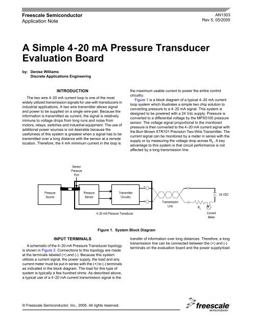
Figure 1. System Block Diagram<br />
<strong>AN1303</strong><br />
Rev 5, 05/<strong>20</strong>05<br />
the maximum usable current to power the entire control<br />
circuitry.<br />
Figure 1 is a block diagram of a typical 4-<strong>20</strong> <strong>mA</strong> current<br />
loop system which illustrates a simple two chip solution to<br />
converting pressure to a 4-<strong>20</strong> <strong>mA</strong> signal. This system is<br />
designed to be powered with a 24 Vdc supply. <strong>Pressure</strong> is<br />
converted to a differential voltage by the MPX5100 pressure<br />
sensor. The voltage signal proportional to the monitored<br />
pressure is then converted to the 4-<strong>20</strong> <strong>mA</strong> current signal with<br />
the Burr-Brown XTR101 Precision Two-Wire Transmitter. The<br />
current signal can be monitored by a meter in series with the<br />
supply or by measuring the voltage drop across R L . A key<br />
advantage to this system is that circuit performance is not<br />
affected by a long transmission line.<br />
Transmission<br />
Line R L<br />
Current<br />
Meter<br />
24 VDC<br />
transfer of information over long distances. Therefore, a long<br />
transmission line can be connected between the (+) and (-)<br />
terminals on the evaluation board and the power supply/load.
D2<br />
1N4565A<br />
6.4 V @ 0.5<strong>mA</strong><br />
<strong>AN1303</strong><br />
PRESSURE INPUT<br />
The device supplied on this topology is an MPX5100DP,<br />
which provides two ports. P1, the positive pressure port, is on<br />
top of the sensor and P2, the vacuum port, is on the bottom of<br />
the sensor. The system can be supplied up to 15 PSI of<br />
positive pressure to P1 or up to 15 PSI of vacuum to P2 or a<br />
differential pressure up to 15 PSI between P1 and P2. Any of<br />
these pressure applications will create the same results at the<br />
sensor output.<br />
Circuit Description<br />
XDCR1<br />
MPX7100<br />
3 2<br />
4 1<br />
R2<br />
1K<br />
The XTR101 current transmitter provides two one-milliamp<br />
current sources for sensor excitation when its bias voltage is<br />
between 12 V and 40 V. The MPX5100 series sensors are<br />
constant voltage devices, so a zener, D2, is placed in parallel<br />
with the sensor input terminals. Because the MPX5100 series<br />
parts have a high impedance the zener and sensor<br />
combination can be biased with just the two milliamps<br />
available from the XTR101.<br />
The offset adjustment is composed of R4 and R6. They are<br />
used to remove the offset voltage at the differential inputs to<br />
the XTR101. R6 is set so a zero input pressure will result in<br />
the desired output of 4 <strong>mA</strong>.<br />
R3 and R5 are used to provide the full scale current span of<br />
16 <strong>mA</strong>. R5 is set such that a 15 PSI input pressure results in<br />
the desired output of <strong>20</strong> <strong>mA</strong>. Thus the current signal will span<br />
R5<br />
50<br />
2 <strong>mA</strong><br />
R3<br />
39<br />
4<br />
5<br />
6<br />
3<br />
1 2 14 7 13 9<br />
Figure 2. Schematic Diagram<br />
16 <strong>mA</strong> from the zero pressure output of 4 <strong>mA</strong> to the full scale<br />
output of <strong>20</strong> <strong>mA</strong>. To calculate the resistor required to set the<br />
full scale output span, the input voltage span must be defined.<br />
The full scale output span of the sensor is 24.8 mV and is ∆VIN to the XTR101. Burr-Brown specifies the following equation<br />
for Rspan . The 40 and 16 mΩ values are parameters of the<br />
XTR101.<br />
Rspan = 40 / [(16 <strong>mA</strong> / ∆Vin) - 0.016 mhos]<br />
= 64 Ω<br />
The XTR101 requires that the differential input voltage at<br />
pins 3 and 4, V2 - V1 be less than 1V and that V2 (pin 4)<br />
always be greater than V1 (pin 3). Furthermore, this<br />
differential voltage is required to have a common mode of 4-6<br />
volts above the reference (pin 7). The sensor produces the<br />
differential output with a common mode of approximately 3.1<br />
volts above its reference pin 1. Because the current of both 1<br />
<strong>mA</strong> sources will go through R2, a total common mode voltage<br />
of about 5.1 volts (1 kΩ x 2 <strong>mA</strong> + 3.1 volts = 5.1 volts) is<br />
provided.<br />
CONCLUSION<br />
This circuit is an example of how the MPX5000 series<br />
sensors can be utilized in an industrial application. It provides<br />
a simple design alternative where remote pressure sensing is<br />
required.<br />
Sensors<br />
2 <strong>Freescale</strong> Semiconductor<br />
10 11<br />
U1<br />
XTR101<br />
R6<br />
100K R4<br />
1M<br />
8<br />
12<br />
4-<strong>20</strong> <strong>mA</strong> <strong>Pressure</strong> <strong>Transducer</strong><br />
R1<br />
750<br />
1/2 W<br />
Q1<br />
MPSA06<br />
D1<br />
1N4002<br />
C1<br />
0.01µF<br />
+ 4-<strong>20</strong> <strong>mA</strong> OUTPUT<br />
- RETURN
Table 1. Parts List for 4-<strong>20</strong> <strong>mA</strong> <strong>Pressure</strong> <strong>Transducer</strong> Evaluation Board<br />
Designator Quantity Description Rating Manufacturer Part Number<br />
1<br />
1<br />
4<br />
4<br />
2<br />
2<br />
C1 1<br />
D1<br />
D2<br />
1<br />
1<br />
Q1 1<br />
R1<br />
R2<br />
R3<br />
R4<br />
R5<br />
R6<br />
1<br />
1<br />
1<br />
1<br />
1<br />
1<br />
U1 1<br />
PC Board<br />
Input/Output Terminals<br />
1/2″ standoffs, Nylon threaded<br />
1/2″ screws, Nylon<br />
5/8″ screws, Nylon<br />
4-40 nuts, Nylon<br />
Capacitor<br />
0.01 µF 50 V<br />
Diodes<br />
100 V Diode<br />
6.4 V Zener<br />
<strong>Freescale</strong><br />
PHX CONT<br />
DEVB126<br />
#1727010<br />
1 A 1N4002<br />
1N4565A<br />
Transistor<br />
NPN Bipolar <strong>Freescale</strong> MPSA06<br />
Resistors, Fixed<br />
750 Ω<br />
1 kΩ<br />
39 Ω<br />
1 MΩ<br />
Resistors, Variable<br />
50 Ω, one turn<br />
100 KΩ, one turn<br />
<strong>AN1303</strong><br />
Sensors<br />
<strong>Freescale</strong> Semiconductor 3<br />
1/2 W<br />
Bourns<br />
Bourns<br />
#3386P-1-500<br />
#3386P-1-104<br />
Integrated Circuit<br />
Two wire current transmitter Burr-Brown XTR101<br />
XDCR1 1<br />
Sensor<br />
High Impedance 15 PSI <strong>Freescale</strong> MPX5100DP<br />
NOTE: All resistors are 1/4 W with a tolerance of 5% unless otherwise noted. All capacitors are 100 volt, ceramic capacitors with a tolerance<br />
of 10% unless otherwise noted.
How to Reach Us:<br />
Home Page:<br />
www.freescale.com<br />
E-mail:<br />
support@freescale.com<br />
USA/Europe or Locations Not Listed:<br />
<strong>Freescale</strong> Semiconductor<br />
Technical Information Center, CH370<br />
1300 N. Alma School Road<br />
Chandler, Arizona 85224<br />
+1-800-521-6274 or +1-480-768-2130<br />
support@freescale.com<br />
Europe, Middle East, and Africa:<br />
<strong>Freescale</strong> Halbleiter Deutschland GmbH<br />
Technical Information Center<br />
Schatzbogen 7<br />
81829 Muenchen, Germany<br />
+44 1296 380 456 (English)<br />
+46 8 52<strong>20</strong>0080 (English)<br />
+49 89 92103 559 (German)<br />
+33 1 69 35 48 48 (French)<br />
support@freescale.com<br />
Japan:<br />
<strong>Freescale</strong> Semiconductor Japan Ltd.<br />
Headquarters<br />
ARCO Tower 15F<br />
1-8-1, Shimo-Meguro, Meguro-ku,<br />
Tokyo 153-0064<br />
Japan<br />
01<strong>20</strong> 191014 or +81 3 5437 9125<br />
support.japan@freescale.com<br />
Asia/Pacific:<br />
<strong>Freescale</strong> Semiconductor Hong Kong Ltd.<br />
Technical Information Center<br />
2 Dai King Street<br />
Tai Po Industrial Estate<br />
Tai Po, N.T., Hong Kong<br />
+800 2666 8080<br />
support.asia@freescale.com<br />
For Literature Requests Only:<br />
<strong>Freescale</strong> Semiconductor Literature Distribution Center<br />
P.O. Box 5405<br />
Denver, Colorado 80217<br />
1-800-441-2447 or 303-675-2140<br />
Fax: 303-675-2150<br />
LDCFor<strong>Freescale</strong>Semiconductor@hibbertgroup.com<br />
<strong>AN1303</strong><br />
Rev 5<br />
05/<strong>20</strong>05<br />
Information in this document is provided solely to enable system and software<br />
implementers to use <strong>Freescale</strong> Semiconductor products. There are no express or<br />
implied copyright licenses granted hereunder to design or fabricate any integrated<br />
circuits or integrated circuits based on the information in this document.<br />
<strong>Freescale</strong> Semiconductor reserves the right to make changes without further notice to<br />
any products herein. <strong>Freescale</strong> Semiconductor makes no warranty, representation or<br />
guarantee regarding the suitability of its products for any particular purpose, nor does<br />
<strong>Freescale</strong> Semiconductor assume any liability arising out of the application or use of any<br />
product or circuit, and specifically disclaims any and all liability, including without<br />
limitation consequential or incidental damages. “Typical” parameters that may be<br />
provided in <strong>Freescale</strong> Semiconductor data sheets and/or specifications can and do vary<br />
in different applications and actual performance may vary over time. All operating<br />
parameters, including “Typicals”, must be validated for each customer application by<br />
customer’s technical experts. <strong>Freescale</strong> Semiconductor does not convey any license<br />
under its patent rights nor the rights of others. <strong>Freescale</strong> Semiconductor products are<br />
not designed, intended, or authorized for use as components in systems intended for<br />
surgical implant into the body, or other applications intended to support or sustain life,<br />
or for any other application in which the failure of the <strong>Freescale</strong> Semiconductor product<br />
could create a situation where personal injury or death may occur. Should Buyer<br />
purchase or use <strong>Freescale</strong> Semiconductor products for any such unintended or<br />
unauthorized application, Buyer shall indemnify and hold <strong>Freescale</strong> Semiconductor and<br />
its officers, employees, subsidiaries, affiliates, and distributors harmless against all<br />
claims, costs, damages, and expenses, and reasonable attorney fees arising out of,<br />
directly or indirectly, any claim of personal injury or death associated with such<br />
unintended or unauthorized use, even if such claim alleges that <strong>Freescale</strong><br />
Semiconductor was negligent regarding the design or manufacture of the part.<br />
<strong>Freescale</strong> and the <strong>Freescale</strong> logo are trademarks of <strong>Freescale</strong> Semiconductor, Inc.<br />
All other product or service names are the property of their respective owners.<br />
© <strong>Freescale</strong> Semiconductor, Inc. <strong>20</strong>05. All rights reserved.


