rnt-popeiler
rnt-popeiler
rnt-popeiler

Create successful ePaper yourself
Turn your PDF publications into a flip-book with our unique Google optimized e-Paper software.
nt-<strong>popeiler</strong><br />
- ENTWICKLUNG<br />
GMBH<br />
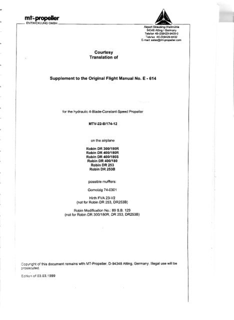
Courtesy<br />
Translation of<br />
Supplement to the Original Flight Manual No. E - 614<br />
for the hydraulic 4-Blade-ConstantSpeed Propeller<br />
Mfv.22-8.1174-12<br />
on the airplane<br />
Robin DR 300/180R<br />
Robln DR 4{t0/180R<br />
Robln DR 400/180S<br />
Robin DR 400/180<br />
Robin DR 253<br />
Robln DR 2538<br />
oossible mufflers:<br />
Gomolzig 74-0301<br />
Hirth FVA 23-V2<br />
(not for Robin DR 253, DR253B)<br />
Robin Modification No.: 89 S.B. 129<br />
(not for Robin DR 300/180R, DR 253, DR253B)<br />
A<br />
Ai.pod SbaubingFwallm0hlc<br />
94348 Atting / Gmany<br />
Telefon 49-(0)942$9409-0<br />
Telefar 4S(0)9429-E432<br />
E-mail: sles@mt-propell€r.com<br />
Copyright of this document remains with MT-Propeller, D-94348 Atting, Germany. lllegal use will be<br />
prosecuted.<br />
Ediiton of 03.03.1999
mt-<br />
ENTWICKLUNG GMBH<br />
Page 1 ofl<br />
Supplement to the Original Flight Manual No. E-614<br />
Edition March 3, 1999<br />
This Supplement to the Original Flight Manual belongs to the aircraft:<br />
Aircraft registration No:<br />
Serial No.:<br />
Year of manufacture:<br />
Airpqrl Sfiaubing-Wallmiihl€<br />
94348 Atting / Gemany<br />
Telefon 49-(D)9429-9409-0<br />
Telefax 4S(0)9429{432<br />
E{alli sales@mt-popells,cm<br />
This SupPlement to the Original Flight Manual contains all supplementat information to operate the<br />
aircraft with the Constant Speed ProDeller MTV-22-81174-12.<br />
The information contained in the Original Flight Manual remsins valid further on, provided<br />
that there are no amendments in this Supplement.<br />
--r[<br />
_l<br />
_t<br />
_r<br />
_l<br />
_r<br />
f<br />
ir<br />
f
Page2 ol7<br />
Supplem€nt to the Original Flight Manual No. F614<br />
Edltlon March 3, 1999<br />
1. GENERAL<br />
fnformation concernino the propellen MW-22-81174-12 see Section 2<br />
Propeller Soinner: MT-Propeller No.: P-274-A<br />
2. LIMITATIONS<br />
Diameter:<br />
Blade angle:<br />
Propeller Speed:<br />
174 cm (68.5 in)<br />
no cut-off allowed<br />
max. allowable take.off power<br />
max. allowable continuous power:<br />
Markings at the tachometer : green arc<br />
yellow arc<br />
red radial line<br />
Placards:<br />
Close to the legbglQgte!,<br />
at station cm 61 (24,0 in) :<br />
low pitch:<br />
11,5" !0,2<br />
high Pitch:<br />
30,0" j0,1'<br />
M'tv-22-8t174-12<br />
2.700 RPM (5 minutes)<br />
2.500 RPM<br />
Alrpert St-aubin$Wdlm ghle<br />
94348 Ailing / Gemany<br />
Teleton 49-(0)942$9409-0<br />
Teletax 49-(0)9429-8432<br />
E-mail: sal€s@mt-propel16r.M<br />
500 to 2.200 and 2.400 to 2.500 RPM<br />
2.200lo 2.400 and 2.500 to 2.700 RPM<br />
2.700 RPM<br />
The airplane may be operated without spinner as well. In this case remove filler plates.<br />
For DR 400/1805:<br />
The a. m. oDeration limitations are valid. The restrictions to 2.600 RPM b€comgs obsolete.<br />
with the contense:<br />
Avoid manifold pressure over 18 inch Hg<br />
between 2.200 RPM and 2.400 RPM<br />
lf the offset of the tachometer can not be corrected to a value below 30 rpm, a placard with the rpm<br />
offset at 2200 rpm, 2300 rpm and 2400 rpm has to be installed close to the tachometer-<br />
The installation of the manifold oressure gauge is marked as follows:<br />
l-M-"-rifdd Pt"*r* I<br />
The installation of Propeller lever is merked as follows:<br />
Prooeller control
ml:<br />
- ENTWICKLUNG GMBH<br />
Page 3 of 7<br />
Supplement to the Original Flight Manual No. ff14<br />
Edition Maroh 3, 1999<br />
3, EMERGENGY PROCEDURES<br />
Airpo.t Slraubing-Wallmiihle<br />
94348 Alting / Gemany<br />
Teleton 49-(0)942$940$0<br />
Telefax 49-(0)9429-8432<br />
E-mail: sales@mt-PrcPell6r.@m<br />
fiffibrcontro|sysem,orifthepitchcontro|fai|s,theprope||erwi||<br />
return to low pitch position (take-otf position)'<br />
Push Propeller Control to maximum and hold propeller-speed below 2700 RPM by the power lever'<br />
Select lower air speed, if applicable.<br />
Monitor oil pressure and oil temperature.<br />
4. NORMALPROCEDURES<br />
Daily Control<br />
Before every flight, check condition of blades and spinner Blade tip play up to 3 mm is allowed,<br />
blade angel play up to 2mm is allowed<br />
No unallowable cracks in blades (refer to Installation and operation Manual F124)<br />
irosion sneets may not be loose. PU Tape has to be installed and o.k,, in other case replace it in the<br />
next 10 operation hours after last check. No oilleakage allowed'<br />
Starting the engine: Propeller position low pitch<br />
Before take off: Throttle<br />
ProPeller lever<br />
Cycle PrcP<br />
if engine is cold<br />
2OOO RPM<br />
high pitch<br />
to 1500 RPM then low Pitch<br />
repeat 3 times<br />
Move the Propel|er lever s|owly, because the propeller MTV-22 is equipped With |ight natula|<br />
"o*po"it" blad'es and responds fister to pitch changes than propellers with metal blades.<br />
After take off and after reaching the safety height, reduce rpm to a value within the green arc of the<br />
tachometer at full throttle, for noise reduction'<br />
fl<br />
--il<br />
-J<br />
-J<br />
_l<br />
_t<br />
:r<br />
-r
Paoe 4 of 7<br />
Suiplement to the Original Fligtrt Manual No' E-614<br />
Edition March 3, 1999<br />
5. PERFORMANCE<br />
Airport Straubing-Walka iihle<br />
94348 Atting / Gemany<br />
Telefon 49-(0)942$940S0<br />
Telefax 49-(0)942$8432<br />
E-mail: sales@mt-propgller.com<br />
The Derformanco data in the original Flight Manual r6main valid except the information Provided in this<br />
Supplement to tha Original Flight Manual'<br />
Take off distances:<br />
Th€ table take off distances in this Supplement of the Original Flight Manual is valid'<br />
ffiffiE.R:<br />
The crimb perfomanca. data for th€ prope'er s€nsenich T'EMBsso-sg<br />
accoding to the Original Flight Manual remain valid'<br />
iir tip""o-aloolfAta: fn-e i^r,,it.iid" s"J^ in nre originat Flight Manual remain valid (Prop€llor<br />
sonsenich 76EMBS$0-58)<br />
I in the original Flight Manuel remain<br />
Foitvp" DR400/180 bzw: DR 400/180s: The information giver<br />
valid except:<br />
Propeller speed:<br />
2.500 RPM<br />
Optimum speed:<br />
160 km/h low Altitudes<br />
1 50 km/h at 15.500 ft
mt-propeiler<br />
- ENTWICKLUNG GMBH<br />
Page 5 oI7<br />
Supplement to the Oilginal Flight Manual No. E-614<br />
Editlon March 3, 1999<br />
-iI<br />
j<br />
---r[<br />
-I<br />
til
mf-prcpeiler<br />
- ENTWICX(LUNG GMBH<br />
Pag€ 6 of 7<br />
Supplement to tho Original Flight Manual No. F614<br />
Editlon March 3, 1999<br />
6. WEIGHT AND BALANCE; LIST OF EQUIPMENT<br />
Original equipment:<br />
Standard propeller (Sensenich 76EMOS$0-0) with spinner:<br />
Engine Lycomlng 0-360-A3A<br />
intended changes:<br />
Propeller MTV-22 with SPinner<br />
Engine Lycoming G360-A1 P<br />
Hydraulic Propellor Governor<br />
Vemier Control Cable 05-10460<br />
Manifold Pressure 7'1 OO-12<br />
Airpott St aubing-Wallmohle<br />
94348 Attlng / G€meny<br />
Telefon 49-(0)94299409-0<br />
Teleiax 49(0)9429{432<br />
Ef, ail: e,s@mt-prcp€ll9r'com<br />
weight = 19,35 kg<br />
arm = 1,38m<br />
mass moment = 26,7 kgm<br />
weight = 131,0 kg<br />
arm = 0,957 m<br />
mass moment = 125,36 kgm<br />
weight = 19,0 k9<br />
arm = 1,4 m<br />
mass moment= 16,6 kgm<br />
weight = 132,45 kg<br />
arm = 0.957 m<br />
mass moment = 126,75 kgm<br />
weight = 1,15 kg<br />
arm = 1,187m<br />
mass moment = 1,365 kgm<br />
weight = 0,7 kg<br />
arm = 0,55 m<br />
mass moment = 0,350 kgm<br />
weight = 0,13 kg<br />
arm = 0,1 m<br />
mass moment = 0,013 kgm<br />
The empty mass moment with Lycoming o.36GA1P and the propeller MTV-22.- is 3,38 kg higher<br />
than with the original Sensenich Propeller.<br />
The empty mass with Lycoming 0!360-Al P and the propeller MTV-22..,<br />
is 3,08 kg higher than with<br />
th€ original Sensenich prop€ller'
mf-prcpelr<br />
ENTWICKLUNG GMBH<br />
Page 7 of 7<br />
supplom€nt to the Original Flight Manual No. E-614<br />
Edition March 3, 1999<br />
Section 7 Description of System and Functlon<br />
The propeller is equipped with an inlinitely variable hydraulic Pitch change mechanism operated by a<br />
hydraulic propeller govemor.<br />
On"" " prop'"ff"r jpeed is set, the govemor keeps the propeller speed constant, independently of<br />
manifold pressure and flight speed.<br />
iropeifei pitctr is operatel by a propeller pitch change knob on the instrument panel.<br />
Pulling the knob results In a decrease of rpm.<br />
rn" s-et rp. is kept constant by the govemor, independent from air speed and throtte setting. lf the<br />
*nJi* po*o is not sufficient to hold the selected Propeller speed, the propeller pitcfi changes to low<br />
pitch.<br />
ine propetler govemor is flanged to the engine' lt is driv-en diectly by the engine'<br />
The propeller govemor oil supply is part of the engine oil syslem'<br />
ln case of oil pres"ure loss due io a failure in the govemor oil system, the proPeller sets to low ptich'<br />
Section E Additional Instructlons<br />
Check of tachometer:<br />
During the annual check of the airplane, the accuracy_of.the.tachometer has to be checked. lf th6<br />
offset of the tachometer can not be corrected to a valui below 30 rpm, a placard with the rpm offset at<br />
2200 rpm, 2300 rpm andz4}O rpm has to be installed dose to the tachometer'<br />
Procedure for towino with hvdraulic constant soeed orooeller:<br />
The Propeller MW-22.... is approved for towing gliders and banner'<br />
Procedure for towino oliders:<br />
Airport StEubing-Wallm0hle<br />
94346 Atinq Ating / Gemany<br />
Tsleton, ,f9-(0)9429-9409-{t<br />
Teletax 4$(0)942+E432<br />
E-mall sal8s@mt-propeller.com<br />
Take off with full throttle and propeller speed set to 2700 rpm, or2500 rpm if the airfield conditions<br />
allow.<br />
Attei reactring tne safety height' propeller speed has to be reduced to 2500 rpm'<br />
Fult throttle remains until releasing the glider.<br />
Climbing with reduced propeller speed, reduces the noise emission-<br />
DeseendwithproPel|erspeedsetto2000rpmandpowersettingbetween15andlSinchmanifo|d<br />
pressure.<br />
Select a descend speed in a way' that a decrease of the cylinder head temperature of 28'C/min<br />
(so'F/min) will not be exceed€d.<br />
All other information remain valid'
AIRCRAFT FLIGHT MANUAL SUPPLEMENT<br />
ELEVATOR ELECTRIC TRIM<br />
AIRCRAFT FLIGHT MANUAL SUPPLEMENT<br />
ELEVATOR ELECTRIC TRIM<br />
This supplement includes the information to be provided to the pilot, as required by the<br />
certification basis.<br />
This supplement supersedes any existing supplement in section 7 concerning the<br />
elevator electric trim.<br />
Revision Date Description DGAC approval<br />
1. GENERAL<br />
1.1. ApplicabilitY<br />
1.2. Description<br />
Dec. 1'1'n, 2002<br />
Original issue<br />
Aircraft tYPe Manufacturer chqnge<br />
DR400/180<br />
DR400/180R<br />
DR400/200R<br />
DR400/500<br />
n'1 32<br />
n"1 32<br />
n'132<br />
n"132<br />
AR 2003<br />
An elevator electric trim tab control can be installed in option. lt comprises a servo-actuator<br />
connected to the trim control system, an ON/OFF switch located on the instruments panel'<br />
a trim UP/DowN control button located on the stick handle and a circuit breaker.<br />
Document n" 1001 1 69 GB Page 112 December 1ltn,2002
2. LIMITATIONS<br />
No change.<br />
AIRCRAFT FLIGHT MANUAL SUPPLEMENT<br />
ELEVATOR ELECTRIC TRIM<br />
3. EMERGENCY PROCEDURES<br />
lf the elevator electric trim malfunctions:<br />
1. Oppose and correct action by means of elevator control if necessary'<br />
Z. Sii tne ebvator trim switch to OFF and disable the elevator trim breaker.<br />
3. Do not attempt to switch it back ON'<br />
4. Manually operate the tab to trim the aircraft.<br />
4. NORMAL PROCEDURES<br />
4.1. Before take-off.<br />
1. Elevator trim breaker..... """""""""""" lN<br />
2. Elevatortrim switch<br />
"""' ON<br />
3. Elevator electric trim control......'.'..<br />
DOWN trim / UP trim<br />
Make sure the elevator trim control wheel and the trim indicator move in the proper<br />
direction,<br />
4. Trim back to take-off Position.<br />
5. Stop using the elevator electric trim during take-off and initial climb'<br />
4.2. Approach<br />
Trim the aircraft for the approach speed.<br />
Stop using elevator electric trim during final approach and landing flare.<br />
5. PERFORMANCE<br />
No change.<br />
6. WEIGHT AND BALANCE<br />
Refer to latest weight and balance record form'<br />
Document n"1001169 GB Page2l2 December 11th,2002<br />
- Jll'<br />
- d<br />
I
DR4OO/180R AIRCRAFT FLIGHT MANUAL<br />
SUPPLEMENT INSTRUMENT PANEL<br />
f lf ustration<br />
Description<br />
CONTENTS<br />
May 2003<br />
.....'.1 I 2<br />
......212
n<br />
o)<br />
o<br />
{o<br />
F<br />
YY<br />
LL I)<br />
T i 2<br />
|l<br />
IT<br />
L €<br />
AIRCRAFT FLIGHT MANUAL DR4OO/{80R<br />
t (Y)<br />
-@=<br />
€ 90<br />
{+<br />
R@<br />
-fla,'@a<br />
( \ !<br />
ffiffi<br />
tr"#<br />
_sfrp<br />
@*<br />
@-m<br />
(le(| oe<br />
ffi<br />
o=<br />
(Y)<br />
(t<br />
o<br />
to<br />
F<br />
o'fl<br />
!t<br />
{<br />
el<br />
t<br />
(t<br />
ao<br />
N<br />
ro<br />
(\|<br />
( ' r 0<br />
( r l {<br />
N<br />
t<br />
fl<br />
(n<br />
May 2003
AI RCRAFT FLI GHT MAN L)AL DR4OO/I lOR<br />
€<br />
€ g :iE $ 6. iH € i t<br />
$ FE *Egg EE.EF FiE€8.-<br />
EEEs iSgE3E F g<br />
E5fiEE$Fgi E3iEE<br />
;EE su ; E<br />
ss s e<br />
* FE $<br />
fFs#E If 5<br />
RRNR RgE$s$ s 8HBgg5$s$ + S+Sg8<br />
9E EA s €=<br />
E.b* E: = JE<br />
igiii5 f ffi-i'ai<br />
5fEF$E E<br />
i+s e<br />
iiFgiigs ieges $gFiggiFig Fgg;<br />
- F{ F) -t roro F € o) gS S S : P I<br />
'lay 2003<br />
F €<br />
o)<br />
.C|<br />
O-NNfrrtt<br />
N N N N N N<br />
2t2