
Create successful ePaper yourself
Turn your PDF publications into a flip-book with our unique Google optimized e-Paper software.
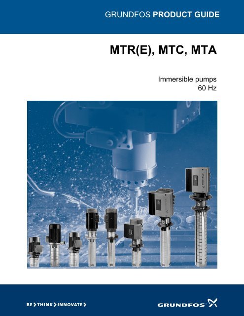
GRUNDFOS PRODUCT GUIDE<br />
<strong>MTR</strong>(E), <strong>MTC</strong>, <strong>MTA</strong><br />
Immersible pumps<br />
60 Hz
2<br />
Contents<br />
Mission<br />
Product data<br />
Introduction 5<br />
Performance range - <strong>MTR</strong>, 60 Hz 6<br />
Performance range - <strong>MTR</strong>E, 60 Hz 6<br />
Performance range - <strong>MTC</strong>, 60 Hz 7<br />
Performance range - <strong>MTA</strong>, <strong>MTA</strong>D 60 Hz 7<br />
Applications 8<br />
Examples of <strong>MTR</strong>E applications 8<br />
Product range - <strong>MTR</strong>(E) 9<br />
Product range - <strong>MTC</strong> 10<br />
Product range - <strong>MTA</strong> 10<br />
Pump 11<br />
<strong>MTR</strong> and <strong>MTC</strong> pumps 11<br />
<strong>MTA</strong> pumps 11<br />
Motor 11<br />
<strong>Grundfos</strong> standard motors - ML and Baldor ® motors 11<br />
Frequency-controlled motors - MLE motors 11<br />
Electrical data 11<br />
Optional motors 12<br />
Motor protection 12<br />
<strong>MTC</strong> pumps 12<br />
Electrical data of <strong>MTC</strong> pumps 12<br />
<strong>MTA</strong> pumps 12<br />
Electrical data 12<br />
Terminal box positions 12<br />
Sound pressure level 12<br />
Shaft seal 13<br />
<strong>MTR</strong>(E) 13<br />
<strong>MTC</strong> 13<br />
Ambient temperature 13<br />
Maximum operating pressure 13<br />
Viscosity 14<br />
Key 14<br />
Viscosity of different oils 15<br />
Pressure loss 16<br />
Control of <strong>MTR</strong>E pumps<br />
Control options for <strong>MTR</strong>E pumps 17<br />
Control panel 17<br />
Remote control 17<br />
External control signals 17<br />
Control modes of <strong>MTR</strong>E pumps 18<br />
Construction<br />
Sectional drawing of <strong>MTR</strong>(E) 1s, 1, 3 and 5 19<br />
Sectional drawing of <strong>MTR</strong>(E) 10, 15 and 20 20<br />
Sectional drawing of <strong>MTR</strong>(E) 32, 45 and 64 21<br />
Material specification - <strong>MTR</strong>(E) - <strong>MTR</strong>I(E) 22<br />
Sectional drawing of <strong>MTC</strong> 2 23<br />
Sectional drawing of <strong>MTC</strong> 4 24<br />
Material specification - <strong>MTC</strong>, <strong>MTC</strong>I 25<br />
Sectional drawing of <strong>MTA</strong> 3, <strong>MTA</strong> 4 26<br />
Material specification - <strong>MTA</strong> 3, <strong>MTA</strong> 4 27<br />
Sectional drawing of <strong>MTA</strong>D 7/7 28<br />
Material specification - <strong>MTA</strong>D 7/7 29<br />
Type keys<br />
<strong>MTR</strong>(E) 30<br />
<strong>MTC</strong> 30<br />
<strong>MTA</strong> 30<br />
Shaft seal 30<br />
Installation<br />
Installation of <strong>MTR</strong>(E) pumps 31<br />
Installation of <strong>MTC</strong> pumps 31<br />
Installation of <strong>MTA</strong> pumps 32<br />
Selection and sizing<br />
Selection of pumps 33<br />
WinCAPS and WebCAPS 36<br />
Minimum inlet pressure - NPSHR 36<br />
Guidelines<br />
How to read the curve charts 37<br />
Guidelines to performance curves 37<br />
Technical data<br />
<strong>MTR</strong>, <strong>MTR</strong>I, <strong>MTR</strong>E 1s, 60 Hz 38<br />
<strong>MTR</strong>, <strong>MTR</strong>I, <strong>MTR</strong>E 3, 60 Hz 42<br />
<strong>MTR</strong>, <strong>MTR</strong>I, <strong>MTR</strong>E 5, 60 Hz 44<br />
<strong>MTR</strong>, <strong>MTR</strong>I, <strong>MTR</strong>E 10, 60 Hz 46<br />
<strong>MTR</strong>, <strong>MTR</strong>I, <strong>MTR</strong>E 15, 60 Hz 48<br />
<strong>MTR</strong>, <strong>MTR</strong>I, <strong>MTR</strong>E 20, 60 Hz 50<br />
<strong>MTR</strong>, <strong>MTR</strong>E 32, 60 Hz 52<br />
<strong>MTR</strong>, <strong>MTR</strong>E 45, 60 Hz 54<br />
<strong>MTR</strong>, <strong>MTR</strong>E 64, 60 Hz 56<br />
<strong>MTC</strong> 2, 60 Hz 58<br />
<strong>MTC</strong> 4, 60 Hz 62<br />
<strong>MTA</strong> 3-180, 60 Hz 64<br />
<strong>MTA</strong> 4-250, 60 Hz 66<br />
<strong>MTA</strong>D 7/7-250, 60 Hz 68
<strong>MTR</strong> motor data<br />
TEFC motors 70<br />
ODP motors 71<br />
MLE motors 71<br />
Pumped liquids<br />
Pumped liquids 72<br />
Pumping of solid particles 72<br />
List of pumped liquids 72<br />
Notes 72<br />
Accessories<br />
Square flange* for <strong>MTR</strong>(E) 1s, 1, 3 and 5 74<br />
Pipework connection 74<br />
Counter flanges for <strong>MTR</strong>(E) 32, 45, and 64 74<br />
R100 remote control 75<br />
Potentiometer for <strong>MTR</strong>E 75<br />
Sensors 75<br />
CIU communication interface units 75<br />
MP 204 motor protector 76<br />
Further product documentation<br />
WebCAPS 77<br />
WinCAPS 78<br />
Contents<br />
3
4<br />
Mission<br />
<strong>MTR</strong>(E), <strong>MTC</strong>, <strong>MTA</strong><br />
It is our mission — the basis of our existence — to successfully develop, produce and sell high-quality pumps and<br />
pumping systems world-wide, contributing to a better quality of life and a healthy environment<br />
Bjerringbro, Denmark<br />
Fresno, California Olathe, Kansas<br />
Monterrey, Mexico Allentown, Pennsylvania Oakville, Ontario<br />
• World's leading pump company<br />
• World's largest manufacturer of circulator pumps, covering more than 50 % of the global market<br />
• World headquarters in Denmark<br />
• North American headquarters in Kansas City - Manufacturing in Fresno, California<br />
• 80 companies in 45 countries<br />
• More than 16 million motors and pumps produced annually worldwide<br />
• North American companies operating in USA, Canada and Mexico<br />
• Continuous reinvestment in growth and development enables the company to<br />
BE responsible, THINK ahead, and INNOVATE
Product data<br />
Introduction<br />
This data booklet deals with <strong>MTR</strong>, <strong>MTR</strong>E, <strong>MTC</strong> and<br />
<strong>MTA</strong> pumps.<br />
Fig. 1 <strong>MTR</strong>, <strong>MTC</strong> and <strong>MTA</strong> pumps<br />
<strong>MTR</strong>, <strong>MTC</strong>, <strong>MTA</strong> pumps are vertical multistage centrifugal<br />
pumps designed for pumping of cooling lubricants<br />
for machine tools, condensate transfer and similar<br />
applications.<br />
The pumps can be used for applications involving spark<br />
machine tools, grinding machines, machine centers,<br />
cooling units, industrial washing machines, filtering<br />
systems etc. The pumps are designed to be mounted<br />
on top of tanks with the pump stack immerged in the<br />
pumped liquid.<br />
<strong>Grundfos</strong> <strong>MTR</strong>, <strong>MTC</strong> and <strong>MTA</strong> pumps come with<br />
various pump sizes and numbers of stages to provide<br />
the flow, the pressure and the length required.<br />
The pumps consist of two main components: The motor<br />
and the pump unit. The motor is a <strong>Grundfos</strong> standard<br />
ML motor or <strong>Grundfos</strong> specified motor designed to<br />
NEMA standards.<br />
The pump unit consists of optimized hydraulics, a<br />
variety of connections, a motor stool, a given number of<br />
chambers and various other parts.<br />
TM02 8540 0404<br />
<strong>MTR</strong>(E), <strong>MTC</strong>, <strong>MTA</strong><br />
<strong>MTR</strong>E - pumps with built-in frequency-converter<br />
Fig. 2 <strong>MTR</strong>E pumps<br />
<strong>MTR</strong>E pumps are built on the basis of <strong>MTR</strong> pumps.<br />
The difference between the <strong>MTR</strong> and the <strong>MTR</strong>E pump<br />
range is the motor. <strong>MTR</strong>E pumps are fitted with an<br />
E-motor, i.e. a motor with built-in frequency control.<br />
The motor of the <strong>MTR</strong>E pump is a <strong>Grundfos</strong> MLE motor<br />
designed to NEMA standards.<br />
Frequency control enables continuously variable<br />
control of motor speed, which makes it possible to set<br />
the pump to operation to any duty point. Continuously<br />
variable control of the motor speed enables adjustment<br />
of the performance to a given requirement.<br />
The pump materials are the same as those of the <strong>MTR</strong><br />
pump range.<br />
Why select a <strong>MTR</strong>E pump?<br />
Select a <strong>MTR</strong>E pump if<br />
• controlled operation is required, i.e. consumption<br />
fluctuates;<br />
• constant pressure is required,<br />
• communication with the pump is required.<br />
Adaptation of performance through frequencycontrolled<br />
speed control offers obvious advantages:<br />
• Energy savings<br />
• Increased comfort<br />
• Control and monitoring of the pump performance.<br />
TM02 8537 0404<br />
5
6<br />
Product data<br />
Performance range - <strong>MTR</strong>, 60 Hz<br />
H<br />
[m]<br />
300<br />
200<br />
100<br />
90<br />
80<br />
70<br />
60<br />
50<br />
40<br />
31<br />
H<br />
[ft]<br />
1000<br />
800<br />
600<br />
500<br />
400<br />
300<br />
200<br />
100<br />
2 3 4 5 6 8 10 15 20 30 40 50 60 80 100 150 200 300 400 500<br />
Q [US GPM]<br />
Performance range - <strong>MTR</strong>E, 60 Hz<br />
H<br />
[m]<br />
200<br />
100<br />
Eff<br />
[%]<br />
80<br />
80<br />
70<br />
60<br />
50<br />
40<br />
30<br />
20<br />
10<br />
60<br />
40<br />
20<br />
0<br />
<strong>MTR</strong><br />
60 Hz<br />
<strong>MTR</strong> 1s <strong>MTR</strong> 1 <strong>MTR</strong> 3<br />
<strong>MTR</strong> 5 <strong>MTR</strong> 10 <strong>MTR</strong> 15 <strong>MTR</strong> 20 <strong>MTR</strong> 32 <strong>MTR</strong> 45 <strong>MTR</strong> 64<br />
1 2 3 4 5 6 7 8 9 10 20 30 40 50 60 Q [m³/h]<br />
2 3 4 5 6 8 10 15 20 30 40 50 60 80 100 150 200 300 400 500<br />
Q [US GPM]<br />
H<br />
[ft]<br />
600<br />
500<br />
400<br />
300<br />
200<br />
100<br />
80<br />
60<br />
50<br />
40<br />
30<br />
Eff<br />
[%]<br />
80<br />
60<br />
40<br />
20<br />
0<br />
<strong>MTR</strong>E 1s <strong>MTR</strong>E 1 <strong>MTR</strong>E 3<br />
<strong>MTR</strong>E 5 <strong>MTR</strong>E 10<br />
<strong>MTR</strong>E 15<br />
<strong>MTR</strong>E 20<br />
<strong>MTR</strong>E 32 <strong>MTR</strong>E 45<br />
<strong>MTR</strong>E<br />
60 Hz<br />
<strong>MTR</strong>E 64<br />
2 3 4 5 6 8 10 15 20 30 40 50 60 80 100 150 200 300 400 500<br />
Q [US GPM]<br />
1 2 3 4 5 6 7 8 9 10 20 30 40 50 60 Q [m³/h]<br />
2 3 4 5 6 8 10 15 20 30 40 50 60 80 100 150 200 300 400 500<br />
Q [US GPM]<br />
<strong>MTR</strong>(E), <strong>MTC</strong>, <strong>MTA</strong><br />
TM03 4250 4110<br />
TM03 4251 2006
Product data<br />
Performance range - <strong>MTC</strong>, 60 Hz<br />
H<br />
[m]<br />
100<br />
80<br />
60<br />
40<br />
20<br />
0<br />
H<br />
[ft]<br />
350<br />
300<br />
250<br />
200<br />
150<br />
100<br />
50<br />
0<br />
0 4 8 12 16 20 24 28 32 Q [US GPM]<br />
0 1 2 3 4 5 6 7 8 Q [m³/h]<br />
Note: <strong>MTC</strong> pumps are not available in Canada.<br />
Performance range - <strong>MTA</strong>, <strong>MTA</strong>D 60 Hz<br />
H<br />
[m]<br />
12<br />
10<br />
8<br />
6<br />
4<br />
2<br />
0<br />
H<br />
[ft]<br />
45<br />
40<br />
35<br />
30<br />
25<br />
20<br />
15<br />
10<br />
5<br />
0<br />
<strong>MTA</strong> 4<br />
<strong>MTA</strong> 3<br />
<strong>MTC</strong> 2<br />
Note: <strong>MTA</strong>, <strong>MTA</strong>D pumps are not available in Canada.<br />
<strong>MTC</strong> 4<br />
<strong>MTA</strong>D 7 <strong>MTA</strong>D 7<br />
1 outlet 2 outlets<br />
<strong>MTR</strong>(E), <strong>MTC</strong>, <strong>MTA</strong><br />
<strong>MTC</strong><br />
60 Hz<br />
<strong>MTA</strong>, <strong>MTA</strong>D<br />
60 Hz<br />
0 10 20 30 40 50 60 70 80 90 100 110 120 130 140 150 Q [US GPM]<br />
0 2 4 6 8 10 12 14 16 18 20 22 24 26 28 30 32 34 36 Q [m³/h]<br />
TM03 4278 2006<br />
TM03 4277 2006<br />
7
8<br />
Product data<br />
Applications<br />
� The pump is suitable for this application.<br />
Examples of <strong>MTR</strong>E applications<br />
An <strong>MTR</strong>E pump is the ideal solution in a number of<br />
applications characterized by a need for variable flow at<br />
constant pressure.<br />
Depending on the nature of the application, the pump<br />
offers energy-savings, increased comfort or improved<br />
processing.<br />
<strong>MTR</strong>E pumps in the service of industry<br />
Industry uses a large number of pumps in many<br />
different applications. Demands on pumps in terms of<br />
pump performance and mode of operation make speed<br />
control a must in many applications.<br />
Some of the applications in which <strong>MTR</strong>E pumps are<br />
used are mentioned below.<br />
Constant pressure<br />
• Washing systems etc.<br />
Example: Within industrial washing systems, <strong>MTR</strong>E<br />
pumps connected to a pressure sensor ensure a<br />
constant pressure in the pipework. From the sensor,<br />
the <strong>MTR</strong>E pump receives input about changes of<br />
pressure resulting from changes in the consumption.<br />
The <strong>MTR</strong>E pump responds to this input by adjusting the<br />
speed and thus the pressure. The constant pressure is<br />
stabilized once more on the basis of a preset setpoint.<br />
Constant temperature<br />
• Industrial cooling systems etc.<br />
Example: In industrial cooling systems, <strong>MTR</strong>E pumps<br />
connected to a temperature sensor will ensure a<br />
constant temperature and lower operating costs<br />
compared to pumps without speed control.<br />
An <strong>MTR</strong>E pump continuously adapts its performance to<br />
the changing demands reflected in the differences in<br />
temperature of the liquid circulating in the cooling<br />
system. Thus the lower the demand for cooling, the<br />
smaller the quantity of liquid circulated in the system<br />
and vice versa.<br />
<strong>MTR</strong>(E), <strong>MTC</strong>, <strong>MTA</strong><br />
Application <strong>MTR</strong>(E) <strong>MTC</strong> <strong>MTA</strong><br />
Lathes - � -<br />
Spark machine tools (EDM) � - �<br />
Grinding machines � � �<br />
Swarf conveyors - � -<br />
Machining centers � � �<br />
Cooling units � � �<br />
Industrial washing machines � � �<br />
Filtering systems � � �<br />
Constant level control<br />
• Condensate systems etc.<br />
Example: In a condensate system, it is important to<br />
monitor and control pump operation to maintain a<br />
constant level of condensate in the system.<br />
An <strong>MTR</strong>E pump connected to a level sensor mounted<br />
in the condensate tank makes it possible to maintain a<br />
constant liquid level.<br />
A constant liquid level ensures optimum and costefficient<br />
operation as a result of a stable production.
Product data<br />
Product range - <strong>MTR</strong>(E)<br />
Range<br />
<strong>MTR</strong><br />
<strong>MTR</strong>E 1s<br />
<strong>MTR</strong>,<br />
<strong>MTR</strong>E 1<br />
<strong>MTR</strong>,<br />
<strong>MTR</strong>E 3<br />
� Standard for > 5 impellers for <strong>MTR</strong> 32, > 3 impellers for <strong>MTR</strong> 45<br />
�� On request<br />
<strong>MTR</strong>,<br />
<strong>MTR</strong>E 5<br />
<strong>MTR</strong>,<br />
<strong>MTR</strong>E 10<br />
<strong>MTR</strong><br />
<strong>MTR</strong>E 15<br />
<strong>MTR</strong><br />
<strong>MTR</strong>E 20<br />
<strong>MTR</strong>(E), <strong>MTC</strong>, <strong>MTA</strong><br />
<strong>MTR</strong> 32 <strong>MTR</strong> 45 <strong>MTR</strong> 64<br />
Nominal flow rate [US GPM] 4.4 8.5 15 30 55 95 110 140 220 340<br />
Nominal flow rate [m 3 /h] 1.0 1.9 3.6 6.8 12.5 21.6 25.2 31.8 50.0 77.2<br />
Temperature range [°F(°C)] +14 to +194 °F (–10 to +90 °C)<br />
Max. pump efficiency [%]<br />
<strong>MTR</strong> pumps<br />
35 49 59 67 70 72 72 76 78 79<br />
Flow range [US GMP] 0.5 - 7 0.9 - 12.8 1.5 - 23.8 3 - 45 5.5 - 68 9.5 - 125 11 - 155 14 - 210 22 - 310 34 - 450<br />
Flow range [m3 /h] 0.1 - 1.6 0.2 - 2.9 0.4 - 5.4 0.7 - 10.2 1.3 - 15.4 2.2 - 28.4 2.5 - 35.2 3.2 - 47.7 5.0 - 70.4 7.8 - 102<br />
Maximum head [H(ft)] 760 795 820 780 835 800 700 970 595 455<br />
Maximum head [psi] 329 344 355 337 361 346 303 420 257 197<br />
Motor power [Hp]<br />
<strong>MTR</strong>E pumps<br />
0.33 - 2 0.33 - 3 0.5 - 5 0.75 - 7.5 1 - 15 2 - 25 3 - 25 5 - 40 7.5 - 40 10 - 40<br />
Flow range [US GMP] 0 - 7 0 - 12.8 0 - 23.8 0 - 45 0 - 68 0 - 125 0 - 155 0 - 210 0 - 310 0 - 450<br />
Flow range [m3 /h] 0 - 1.6 0 - 2.9 0 - 5.4 0 - 10.2 0 - 15.4 0 - 28.4 0 - 35.2 0 - 47.7 0 - 70.4 0 - 102<br />
Maximum head [H(ft)] 760 795 820 780 585 335 275 240 120 100<br />
Maximum head [psi] 329 344 355 337 253 145 119 103 51 43<br />
Motor power [Hp]<br />
Material variants<br />
0.5 - 2 0.5 - 3 0.5 - 5 0.75 - 7.5 1 - 10 2 - 10 3 - 10 5 - 10 7.5 - 10 10<br />
<strong>MTR</strong> (AISI 304/cast iron) � � � � � � � � � �<br />
<strong>MTR</strong>I (AISI 316/AISI 304) � � � � � � � - - -<br />
Pipe connection<br />
Internal thread [NPT] 1.25" 1.25" 1.25" 1.25" 2" 2" 2" - - -<br />
Flange ANSI Class 125# - - - - - - - 2.5" 3.0" 3.0"<br />
Flange ANSI Class 250# - - - - - - - 2.5"�3.0”� -<br />
Installation length [inches]<br />
<strong>MTR</strong> 6.3-24 6.3-24 6.3-23.3 6.7-30 5.8-29.4 7-33.6 7-33.6 8.8-41.9 9.6-41.1 9.8-42.3<br />
<strong>MTR</strong>E<br />
Shaft seal<br />
7.7-24 7.7-24 7-23.3 7.7-30 5.8-29.4 7-33.6 7-33.6 8.8-41.9 9.6-41.1 9.8-42.3<br />
HUUV � � � � � � � � � �<br />
HUUE�� � � � � � � � � � �<br />
HUUK�� � � � � � � � � � �<br />
HQQE�� � � � � � � � � � �<br />
HQQV�� � � � � � � � � � �<br />
9
10<br />
Product data<br />
Product range - <strong>MTC</strong><br />
Range <strong>MTC</strong> 2 <strong>MTC</strong> 4<br />
Nominal flow rate [US GPM] 13 25<br />
Nominal flow rate [m3 /h] 3.0 5.7<br />
Temperature range [°F(°C)] +14 to +194 °F (–10 to +90 °C)<br />
Max. pump efficiency [%] 44 44<br />
Flow range [US GPM] 1.3 - 17.5 2.5 - 35.5<br />
Flow range [m 3 /h] 0.3 - 4.0 0.6 - 8.1<br />
Maximum head [H(ft)] 360 220<br />
Maximum head [psi] 155 95<br />
Motor power [Hp]<br />
Material variants<br />
0.25 - 2.0 0.5 - 2.1<br />
<strong>MTC</strong> (AISI 304/cast iron) � �<br />
<strong>MTC</strong>I (AISI 304/cast iron) � �<br />
Pipe connection<br />
Internal thread [NPT]<br />
Installation length<br />
0.75" 0.75"<br />
inches<br />
Shaft seal<br />
5.7 - 11.4 5.7 - 12.1<br />
AUUV � �<br />
AUUE� � �<br />
� On request.<br />
Product range - <strong>MTA</strong><br />
<strong>MTR</strong>(E), <strong>MTC</strong>, <strong>MTA</strong><br />
Range <strong>MTA</strong> 3 <strong>MTA</strong> 4 <strong>MTA</strong>D 7 - 1 outlet <strong>MTA</strong>D 7 - 2 outlets<br />
Nominal flow rate [US GPM] 22 27 80 80<br />
Nominal flow rate [m3 /h] 5.0 6.1 18.2 18.2<br />
Temperature range [°F(°C)] +14 to +194 °F (–10 to +90 °C)<br />
Max. pump efficiency [%] 30 32 38 38<br />
Flow range [US GPM] 0 - 37 0 - 51 0 - 80 0 - 160<br />
Flow range [m3 /h] 0 - 8.4 0 - 11.6 0 - 18.2 0 - 36.3<br />
Maximum head [H(ft)] 33 45 46 46<br />
Maximum head [psi] 14 19.5 20 20<br />
Motor power P1 [Hp]<br />
Material variants<br />
0.35 - 0.45 0.5 - 0.75 1.2 - 2.1 1.2 - 2.1<br />
<strong>MTA</strong> (AISI 304/cast iron) � � � �<br />
Pipe connection<br />
Internal thread [NPT]<br />
Installation length<br />
0.75" 0.75" 1.25" 1.25"<br />
inches 7.1 9.8 9.8 9.8
Product data<br />
Pump<br />
<strong>MTR</strong> and <strong>MTC</strong> pumps<br />
Motor<br />
Shaft seal<br />
Impeller<br />
Fig. 3 Photo of an <strong>MTR</strong> pump<br />
The pump is a vertical multistage centrifugal pump with<br />
mechanical shaft seal.<br />
Mounting flange dimensions according to DIN 5440.<br />
<strong>Grundfos</strong> offers the following types of pipework<br />
connection for <strong>MTR</strong> pumps:<br />
The pump is fitted with closed impellers offering<br />
optimum hydraulic efficiency and minimum power<br />
consumption.<br />
The pumps are available in two versions<br />
Coupling<br />
Chambers<br />
Connection Code Description<br />
Threaded NPT NPT threads (National Pipe Thread)<br />
Flange ANSI Flanged connection<br />
• Standard range with wetted parts of cast iron and<br />
stainless steel<br />
• Stainless steel version (<strong>MTR</strong>I) with all wetted parts<br />
of stainless steel AISI 304.<br />
Note: The <strong>MTR</strong>I version is to be used in applications<br />
where the pumped liquid can be corrosive.<br />
To meet specific depths of tanks or containers, the<br />
immersible length of the pump can be varied using<br />
empty chambers.<br />
TM02 8536 0404<br />
<strong>MTR</strong>(E), <strong>MTC</strong>, <strong>MTA</strong><br />
<strong>MTA</strong> pumps<br />
The <strong>MTA</strong> pumps are one-chamber or two-chamber<br />
vertical centrifugal pumps (<strong>MTA</strong>D). <strong>MTA</strong>D has two<br />
separate outlets.<br />
<strong>MTA</strong> pumps are fitted with open impellers for use in<br />
unfiltered coolants.<br />
A 0.16" strainer is fitted on the retainer. The strainer<br />
can be removed by the user if needed.<br />
Mounting flange dimensions are according to DIN 5440.<br />
The <strong>MTA</strong> pump has no shaft seal.<br />
Motor<br />
<strong>Grundfos</strong> standard motors - ML and<br />
Baldor ® motors<br />
<strong>MTR</strong> and <strong>MTR</strong>I pumps are fitted with a <strong>Grundfos</strong><br />
specified motor. The motors are all heavy-duty 2-pole,<br />
NEMA C-face motors.<br />
Frequency-controlled motors - MLE motors<br />
<strong>MTR</strong>E and <strong>MTR</strong>IE pumps are fitted with a totally<br />
enclosed, fan-cooled, 2-pole frequency-controlled<br />
motor.<br />
From 0.5 Hp to 1.5 Hp <strong>Grundfos</strong> offers <strong>MTR</strong>(E) pumps<br />
fitted with single-phase MLE motors (1 x 208-230 V).<br />
From 1.0 Hp to 10 Hp <strong>Grundfos</strong> offers <strong>MTR</strong>E pumps<br />
fitted with three-phase MLE motors (3 x 460-480 V).<br />
Electrical data<br />
Mounting<br />
designation<br />
Insulation<br />
class<br />
Efficiency<br />
class *<br />
Enclosure<br />
class<br />
60 Hz<br />
Standard<br />
voltages<br />
Approvals:<br />
<strong>Grundfos</strong> ML<br />
and MLE<br />
Approvals:<br />
Baldor ®<br />
NEMA<br />
F & B<br />
Energy efficient / EPAct<br />
Premium efficiency - on request<br />
TEFC - Totally Enclosed Fan Cooled<br />
(<strong>Grundfos</strong> standard)<br />
ODP - Open Drip Proof - on request<br />
1 x 115/208-230 V<br />
3 x 208-230/460 V<br />
3 x 575 V<br />
The motors are rated for:<br />
cURus and CE<br />
The motors are rated for:<br />
UR and CSA<br />
®<br />
* 1 - 10 Hp ML motors are premium efficiency as standard<br />
11
12<br />
Product data<br />
Optional motors<br />
The <strong>Grundfos</strong> standard range of motors covers a wide<br />
variety of application demands. However, for special<br />
applications or operating conditions, custom-built motor<br />
solutions can be provided.<br />
For special applications or operating conditions,<br />
<strong>Grundfos</strong> offers custom-built motors such as:<br />
• explosion proof motors,<br />
• motors with anti-condensation heating unit,<br />
• low-noise motors,<br />
• premium efficiency motors,<br />
• motors with thermal protection.<br />
Motor protection<br />
ML motors<br />
Three-phase motors must be connected to a motor<br />
starter in accordance with local regulations.<br />
MLE motors<br />
<strong>MTR</strong>(E) pumps require no external motor protection.<br />
The MLE motor incorporates thermal protection against<br />
slow overloading and blocking (IEC 11: TP 211). A<br />
circuit breaker is required to protect the power cord to<br />
the motor.<br />
<strong>MTC</strong> pumps<br />
<strong>MTC</strong> pumps are fitted with an integrated <strong>Grundfos</strong><br />
motor where the rotor shaft is used as pump shaft.<br />
This gives the pump a compact design.<br />
<strong>MTC</strong> motors are totally enclosed, fan-cooled, 2-pole<br />
<strong>Grundfos</strong> standard motors.<br />
Electrical data of <strong>MTC</strong> pumps<br />
Insulation class F<br />
Efficiency class<br />
EFF2<br />
EFF1 available on request<br />
Enclosure class TEFC - Totally Enclosed Fan Cooled<br />
Supply voltage, 60 Hz<br />
(Tolerance ±10%)<br />
3 x 208-230/460 V<br />
As standard all <strong>MTC</strong> motors are supplied with CE<br />
approval.<br />
<strong>MTR</strong>(E), <strong>MTC</strong>, <strong>MTA</strong><br />
<strong>MTA</strong> pumps<br />
The pump is fitted with a totally enclosed, fan-cooled<br />
motor.<br />
Electrical data<br />
Insulation class F<br />
Efficiency class Standard efficiency<br />
Enclosure class TEFC Totally Enclosed Fan Cooled (IP54)<br />
60 Hz<br />
ML 63<br />
<strong>MTA</strong> 3, 4<br />
3 x 208-277/360-480 V<br />
Standard voltages ML 80<br />
<strong>MTA</strong>D 7/7<br />
3 x 208-266/360-460 V<br />
Terminal box positions<br />
As standard <strong>MTR</strong>(E) and <strong>MTC</strong> pumps have their<br />
terminal box mounted in position 6 o’clock of the pump;<br />
however other positions are possible.<br />
Note: On <strong>MTC</strong> pumps it is not possible to mount the<br />
terminal box in position 12 as the terminal box does not<br />
fit in that position.<br />
On <strong>MTA</strong> pumps it is only possible to mount the terminal<br />
box in position 6 o’clock.<br />
Position<br />
6 o’clock<br />
Standard<br />
Position<br />
9 o’clock<br />
Fig. 4 Terminal box positions<br />
Sound pressure level<br />
Position<br />
12 o’clock<br />
Position<br />
3 o’clock<br />
All <strong>MTR</strong>(E), <strong>MTC</strong> and <strong>MTA</strong> pumps have a sound<br />
pressure level below 70 dB(A).<br />
TM02 7777 4003
Product data<br />
Shaft seal<br />
The operating range of the shaft seal depends on<br />
operating pressure, pump type, type of shaft seal and<br />
liquid temperature.<br />
<strong>MTR</strong>(E)<br />
p<br />
[psi]<br />
400<br />
300<br />
200<br />
100<br />
Shaft seal Description<br />
HUUV<br />
<strong>MTR</strong> pumps with EPDM elastomers in the shaft seals<br />
(HUUE) can run in the temperature range from 194 °F<br />
to 248 °F. Closed strap nuts with o-rings and plugging<br />
of the shaft seal drain hole may also be required at<br />
temperatures above 212 °F (see page 31).<br />
<strong>MTC</strong><br />
0<br />
p<br />
[psi]<br />
400<br />
300<br />
200<br />
100<br />
0<br />
O-ring seal (cartridge type), balanced,<br />
tungsten carbide/tungstencarbide,<br />
FKM<br />
Shaft seal Description<br />
AUUV<br />
HUUV<br />
0 20 40 60 80 100 120 140 160 180 200 220<br />
T [°F]<br />
AUUV<br />
O-ring seal with fixed seal<br />
driver, tungsten carbide/tungsten<br />
carbide, FKM<br />
TM03 4270 2006<br />
Temperature range<br />
[°F]<br />
+14 °F to 194 °F<br />
0 20 40 60 80 100 120 140 160 180 200 220<br />
T [°F]<br />
TM03 4271 2006<br />
Temperature range<br />
[°F]<br />
+14 °F to 194 °F<br />
Ambient temperature<br />
<strong>MTR</strong>(E), <strong>MTC</strong>, <strong>MTA</strong><br />
Maximum ambient temperature +104 °F (+40 °C).<br />
If the ambient temperature exceeds +104 °F (+40 °C) or<br />
if the motor is located 3280 ft (1000 m) above sea level,<br />
the motor output (P 2) must be reduced due to the low<br />
density and consequently low cooling effect of the air.<br />
In such cases, it may be necessary to use a motor with<br />
a higher output.<br />
Key<br />
P2<br />
[%]<br />
100<br />
2<br />
90<br />
80<br />
70<br />
60<br />
50<br />
1<br />
60 80 100 120 140 160 180<br />
T [°F]<br />
3280 7382 11483 15584 ft<br />
Fig. 5 Relationship between motor output (P2 ) and<br />
ambient temperature/altitude<br />
Pos. Description<br />
1 NEMA Energy Efficient motors<br />
2 NEMA Premium Efficiency motors<br />
Example: From the above figure and key appears that<br />
P 2 must be reduced to 88 % when a pump with a NEMA<br />
Premium Efficiency, ML motor is installed 15584 feet<br />
above sea level. At an ambient temperature of 167 °F,<br />
P 2 of an Energy Efficient motor must be reduced to<br />
74 % of rated output.<br />
Maximum operating pressure<br />
Immersible Pump Model<br />
Maximum Permissible<br />
Operating Pressure<br />
NPT Threads ANSI Flange<br />
<strong>MTR</strong>(I) 1s --> <strong>MTR</strong>(I) 5 362 psi --<br />
<strong>MTR</strong>(I) 10 --> <strong>MTR</strong>(I) 20 362 psi --<br />
<strong>MTR</strong>(I) 32-2/1-1 --> <strong>MTR</strong>(I) 32-5 -- 232 psi<br />
<strong>MTR</strong>(I) 32-6 --> <strong>MTR</strong>(I) 32-8 -- 362 psi<br />
<strong>MTR</strong>(I) 32-9 --> <strong>MTR</strong>(I) 32-11-2 -- 435 psi<br />
<strong>MTR</strong>(I) 45-2/1 --> <strong>MTR</strong>(I) 45-3 -- 232 psi<br />
<strong>MTR</strong>(I) 45-4 --> <strong>MTR</strong>(I) 45-5 -- 362 psi<br />
<strong>MTR</strong>(I) 64-2/1-1 --> <strong>MTR</strong>(I) 64-4-2 -- 232 psi<br />
<strong>MTC</strong> 2 --> <strong>MTC</strong> 4 116 psi --<br />
<strong>MTA</strong> 3 15 psi --<br />
<strong>MTA</strong> 4 20 psi --<br />
<strong>MTA</strong>D 7 20 psi --<br />
TM03 4272 2006<br />
13
14<br />
Product data<br />
Viscosity<br />
<strong>MTR</strong> 1s, 1, 3, 5 can pump up to 50 cst. <strong>MTR</strong> 10, 15, 20,<br />
32, 45, 64 can pump up to 100 cst.<br />
The pumping of liquids with densities or kinematic<br />
viscosities higher than those of water will cause a<br />
considerable pressure drop, a drop in the hydraulic<br />
performance and a rise in the power consumption.<br />
H [ft]<br />
320<br />
280<br />
240<br />
200<br />
160<br />
120<br />
80<br />
40<br />
0<br />
0<br />
H [ft]<br />
700<br />
600<br />
500<br />
400<br />
300<br />
200<br />
100<br />
0<br />
0<br />
H [ft]<br />
400<br />
360<br />
320<br />
280<br />
240<br />
200<br />
160<br />
120<br />
80<br />
40<br />
0<br />
0<br />
Key<br />
1<br />
<strong>MTR</strong> 5-10/10<br />
5 10 15 20 25 30 35 Q [US GPM]<br />
1<br />
<strong>MTR</strong> 20-10/10<br />
20 40 60 80 100 120 Q [US GPM]<br />
1<br />
50 100 150 200 250 300 350<br />
<strong>MTR</strong> 64-3/3<br />
Q [US GPM]<br />
TM03 4309 2006<br />
TM03 4312 2006<br />
TM03 4315 2006<br />
H [ft]<br />
320<br />
280<br />
240<br />
200<br />
160<br />
120<br />
80<br />
40<br />
0<br />
0<br />
H [ft]<br />
700<br />
600<br />
500<br />
400<br />
300<br />
200<br />
100<br />
0<br />
0<br />
2<br />
5 10 15 20 25 30<br />
2<br />
20 40 60 80 100<br />
<strong>MTR</strong>(E), <strong>MTC</strong>, <strong>MTA</strong><br />
In such situations the pump should be equipped with a<br />
larger motor. If in doubt, contact <strong>Grundfos</strong>.<br />
The following examples show the drop in the hydraulic<br />
performance of <strong>MTR</strong>(E) pumps pumping oil with a<br />
density of 54.4 lb/ft 3 but with three different kinematic<br />
viscosities.<br />
<strong>MTR</strong> 5-10/10<br />
Q [US GPM]<br />
<strong>MTR</strong> 20-10/10<br />
Q [US GPM]<br />
Fig. 6 Drop in the hydraulic performance of <strong>MTR</strong>(E) pumps pumping oil with three different kinematic viscosities.<br />
Position Description<br />
1<br />
2<br />
3<br />
H [ft]<br />
400<br />
360<br />
320<br />
280<br />
240<br />
200<br />
160<br />
120<br />
80<br />
40<br />
0<br />
0<br />
Kinematic viscosity: 16 Cst.<br />
Density: 54.4 lb/ft 3<br />
Kinematic viscosity: 32 Cst.<br />
Density: 54.4 lb/ft 3<br />
Kinematic viscosity: 75 Cst.<br />
Density: 54.4 lb/ft 3<br />
Immersible Pump Model Maximum Kinematic Viscosity<br />
<strong>MTR</strong> 1s through <strong>MTR</strong> 10<br />
<strong>MTR</strong> 15 through <strong>MTR</strong> 64<br />
50 Cst.<br />
100 Cst.<br />
2<br />
<strong>MTR</strong> 64-3/3<br />
50 100 150 200 250 300 350 Q [US GPM]<br />
TM03 4310 2006<br />
TM03 4313 2006<br />
TM03 4316 2006<br />
H [ft]<br />
700<br />
600<br />
500<br />
400<br />
300<br />
200<br />
100<br />
0<br />
0<br />
H [ft]<br />
400<br />
360<br />
320<br />
280<br />
240<br />
200<br />
160<br />
120<br />
80<br />
40<br />
0<br />
0<br />
10 20 30 40 60<br />
50 70 80 90 100<br />
<strong>MTR</strong> 20-10/10<br />
Q [US GPM]<br />
For further information about pump performance when<br />
pumping liquids with densities or kinematic viscosities<br />
higher than those of water, see WinCAPS.<br />
WinCAPS is a product selection program offered by<br />
<strong>Grundfos</strong>, see page 77.<br />
3<br />
3<br />
50 100 150 200 250 300<br />
<strong>MTR</strong> 64-3/3<br />
Q [US GPM]<br />
Immersible Pump Model Maximum Kinematic Viscosity<br />
<strong>MTC</strong> 50 Cst.<br />
<strong>MTA</strong> / <strong>MTA</strong>D 50 Cst.<br />
TM03 4314 2006<br />
TM03 4317 2006
Product data<br />
Viscosity of different oils<br />
The curves below show the viscosity of different oils in<br />
relation to oil temperature.<br />
Centistokes<br />
100<br />
90<br />
80<br />
70<br />
60<br />
50<br />
40<br />
30<br />
20<br />
10<br />
9<br />
8<br />
Fig. 7 Viscosity of different oils in relation to oil temperature<br />
Key to viscosities of different oils<br />
Curve number Type of oil<br />
1 Gear oil<br />
2 Motor oil (20W-50)<br />
3 Hydraulic oil (ISO VG46)<br />
4 Cutting oil<br />
5 Thermal oil<br />
6 Hydraulic oil (ISO VG10)<br />
7 Grinding oil<br />
8 Honing oil<br />
7<br />
6<br />
5<br />
4<br />
3<br />
6<br />
7<br />
8<br />
5 4 3 2 1<br />
-10 0 10 20 30 40 50 60 70 80 T [°C]<br />
20 40 60 80 100 120 140 160 180 T [°F]<br />
<strong>MTR</strong>(E), <strong>MTC</strong>, <strong>MTA</strong><br />
TM03 8140 0607<br />
15
16<br />
Product data<br />
Pressure loss<br />
During operation pressure losses occur in all centrifugal<br />
pumps.<br />
The below curves illustrate the pressure losses for<br />
pumped liquid passing through one empty chamber. An<br />
empty chamber is a chamber without an impeller.<br />
H<br />
[m]<br />
0.14<br />
0.12<br />
0.10<br />
0.08<br />
0.06<br />
0.04<br />
0.02<br />
0.00<br />
Fig. 8 Pressure losses of pumped liquid passing through<br />
an empty chamber for <strong>MTR</strong> 1s and <strong>MTR</strong> 1 pumps<br />
H<br />
[m]<br />
0.4<br />
0.3<br />
0.2<br />
0.1<br />
0.0<br />
H<br />
[ft]<br />
0.45<br />
0.40<br />
0.35<br />
0.30<br />
0.25<br />
0.20<br />
0.15<br />
0.10<br />
0.05<br />
0.00<br />
H<br />
[ft]<br />
1.4<br />
1.2<br />
1.0<br />
0.8<br />
0.6<br />
0.4<br />
0.2<br />
0.0<br />
<strong>MTR</strong>1S<br />
<strong>MTR</strong><br />
60 Hz<br />
<strong>MTR</strong> 1<br />
0 2 4 6 8 10 Q [US GPM]<br />
0.0 0.5 1.0 1.5 2.0 2.5 Q [m³/h]<br />
<strong>MTR</strong> 3<br />
<strong>MTR</strong> 5<br />
<strong>MTR</strong><br />
60 Hz<br />
0 5 10 15 20 25 30 35 Q [US GPM]<br />
0 1 2 3 4 5 6 7 8 9 Q [m³/h]<br />
Fig. 9 Pressure losses of pumped liquid passing through<br />
an empty chamber for <strong>MTR</strong> 3 and <strong>MTR</strong> 5 pumps<br />
TM03 4273 2006<br />
TM03 4274 2006<br />
H<br />
[m]<br />
1.4<br />
1.2<br />
1.0<br />
0.8<br />
0.6<br />
0.4<br />
0.2<br />
0.0<br />
H<br />
[ft]<br />
4.5<br />
4.0<br />
3.5<br />
3.0<br />
2.5<br />
2.0<br />
1.5<br />
1.0<br />
0.5<br />
0.0<br />
<strong>MTR</strong>(E), <strong>MTC</strong>, <strong>MTA</strong><br />
Fig. 10 Pressure losses of pumped liquid passing through<br />
an empty chamber for <strong>MTR</strong> 10, <strong>MTR</strong> 15 and <strong>MTR</strong><br />
20 pumps<br />
As <strong>MTR</strong>(E) 32, 45 and 64 pumps have holes in the<br />
guide vanes, no pressure losses occur in the empty<br />
chambers of these pumps.<br />
Calculation of the reduced head of a pump with<br />
empty chambers<br />
Calculation of pressure loss in empty chambers<br />
From the pressure loss curves and the pump<br />
performance curves, it is possible to calculate the<br />
reduced head of a pump with empty chambers.<br />
The calculation can be made as shown below.<br />
Example:<br />
<strong>MTR</strong> 10<br />
<strong>MTR</strong> 15<br />
0 20 40 60 80 100 120 Q [US GPM]<br />
0 5 10 15 20 25 30 Q [m³/h]<br />
Pump type <strong>MTR</strong> 5-18/7<br />
Flow Q (duty point) 25 [gpm]<br />
Head (duty point) 180 [ft]<br />
<strong>MTR</strong><br />
60 Hz<br />
The selected pump is an <strong>MTR</strong> 5-18/7 with 11 empty<br />
chambers. From the above pressure loss curve of<br />
<strong>MTR</strong> 5, it appears that the pressure loss of each empty<br />
chamber at 25 [gpm] is 0.46 [ft]. This results in a total<br />
pressure loss of:<br />
Total pressure loss = 0.46 × 11 = 5 [ft]<br />
<strong>MTR</strong> 20<br />
The reduced head of the <strong>MTR</strong> 5-18/7 pump including<br />
pressure losses caused by empty chambers is:<br />
Head = 185 – 5 =<br />
180 [ft]<br />
The head 185 ft is read from the performance curve for<br />
an <strong>MTR</strong> 5-7.<br />
TM02 8581 0404
Control of <strong>MTR</strong>E pumps<br />
Control options for <strong>MTR</strong>E pumps<br />
Communication with <strong>MTR</strong>E pumps is possible by<br />
means of<br />
• a control panel,<br />
• remote control (<strong>Grundfos</strong> R100),<br />
• external digital or analog control signals,<br />
• an RS485 bus interface.<br />
The purpose of controlling a <strong>MTR</strong>E pump is to monitor<br />
and control the pressure, temperature, flow or liquid<br />
level of the system.<br />
Control panel<br />
The control panel of the <strong>MTR</strong>E pump terminal box<br />
makes it possible to change the setpoint settings<br />
manually.<br />
Light fields<br />
Indicator lights<br />
Fig. 11 Control panel on <strong>MTR</strong>E pump<br />
Remote control<br />
The R100 remote control produced by <strong>Grundfos</strong> is<br />
available as an accessory. See page 75.<br />
The operator communicates with the <strong>MTR</strong>E pump by<br />
pointing the IR-signal transmitter at the control panel of<br />
the <strong>MTR</strong>E pump terminal box.<br />
Fig. 12 R100 remote control<br />
Buttons<br />
On the R100 display it is possible to monitor and<br />
change control modes and settings of the <strong>MTR</strong>E pump.<br />
TM00 7600 0404<br />
TM00 4498 2802<br />
<strong>MTR</strong>(E), <strong>MTC</strong>, <strong>MTA</strong><br />
External control signals<br />
Communication with the <strong>MTR</strong>E pump is possible even<br />
though the operator is not present near the <strong>MTR</strong>E<br />
pump. Communication is enabled by connecting the<br />
<strong>MTR</strong>E pump to an external control or monitoring<br />
system allowing the operator to monitor and change<br />
control modes and setpoint settings of the <strong>MTR</strong>E pump.<br />
LON connection<br />
GENIbus<br />
connection<br />
<strong>MTR</strong>E pump<br />
Central<br />
management<br />
system<br />
LON interface<br />
Fig. 13 Example of a central management system with<br />
LON interface<br />
TM02 6592 1103<br />
17
18<br />
Control of <strong>MTR</strong>E pumps<br />
Control modes of <strong>MTR</strong>E pumps<br />
<strong>MTR</strong>E pumps can be connected to an external sensor<br />
enabling control of pressure, differential pressure,<br />
temperature, level, differential temperature or flow.<br />
<strong>MTR</strong>E pumps can be set to two control modes -<br />
controlled or uncontrolled operation.<br />
In controlled operating mode the pump is<br />
automatically operating according to the desired<br />
setpoint of the control parameter. The illustration below<br />
shows a pump with flow control as an example of<br />
controlled operation.<br />
In uncontrolled operating mode the pump operates<br />
according to the constant curve set.<br />
Controlled operation Uncontrolled operation<br />
H<br />
Qset<br />
Constant flow Constant curve<br />
Fig. 14 Controlled and uncontrolled operating modes<br />
The pumps are set to uncontrolled operation from<br />
factory.<br />
Besides normal duty (constant flow and constant curve)<br />
the operating modes Stop, Min. or Max. are available.<br />
Fig. 15 Max. and min. curves<br />
H<br />
Q<br />
H<br />
Min.<br />
Max.<br />
Q<br />
Q<br />
TM01 0684 1997<br />
TM00 5547 0995<br />
<strong>MTR</strong>(E), <strong>MTC</strong>, <strong>MTA</strong>
Construction<br />
Sectional drawing of <strong>MTR</strong>(E) 1s, 1, 3 and 5<br />
8<br />
2<br />
51<br />
49<br />
4<br />
45<br />
122<br />
121<br />
105<br />
85<br />
<strong>MTR</strong>(E), <strong>MTC</strong>, <strong>MTA</strong><br />
TM02 8687 0704<br />
19
20<br />
Construction<br />
Sectional drawing of <strong>MTR</strong>(E) 10, 15 and 20<br />
1a<br />
8<br />
2<br />
51<br />
49<br />
45<br />
4<br />
122<br />
121<br />
105<br />
84<br />
<strong>MTR</strong>(E), <strong>MTC</strong>, <strong>MTA</strong><br />
TM02 8688 0704
Construction<br />
Sectional drawing of <strong>MTR</strong>(E) 32, 45 and 64<br />
105<br />
49<br />
51<br />
84<br />
1a<br />
2<br />
8<br />
45<br />
47<br />
4<br />
<strong>MTR</strong>(E), <strong>MTC</strong>, <strong>MTA</strong><br />
TM02 8689 0704<br />
21
22<br />
Construction<br />
Material specification - <strong>MTR</strong>(E) - <strong>MTR</strong>I(E)<br />
Pos. Description Materials EN/DIN AISI/ASTM<br />
1a Motor stool<br />
Cast iron<br />
EN-GJL-200<br />
* CF 8M is cast equivalent of AISI 316 stainless steel<br />
0.6020 ASTM 25B<br />
2 Pump head<br />
Cast iron<br />
EN-GJS-500-7<br />
Stainless steel<br />
(<strong>MTR</strong>I)<br />
0.7050<br />
1.4408<br />
ASTM 80-55-06<br />
CF 8M*<br />
4 Chamber complete Stainless steel 1.4301 AISI 304<br />
8 Coupling<br />
Sinter metal<br />
Cast iron 0.7040 ASTM 60-40-18<br />
121<br />
Retainer for suction<br />
strainer<br />
Stainless steel 1.4301 AISI 304<br />
45 Neck ring PTFE<br />
47 Bearing ring SIC<br />
49 Impeller Stainless steel 1.4301 AISI 304<br />
51<br />
Pump shaft,<br />
<strong>MTR</strong> 1s, 1, 3, 5<br />
Pump shaft,<br />
<strong>MTR</strong> 10, 15, 20<br />
<strong>MTR</strong> 32, 45, 64<br />
Stainless steel 1.4401 AISI 316<br />
Stainless steel 1.4057 AISI 431<br />
84<br />
Suction strainer, ø0.16”<br />
holes<br />
Stainless steel 1.4301 AISI 304<br />
85 Strainer Stainless steel 1.4301 AISI 304<br />
105 Shaft seal HUUV/HUUE<br />
122 Priming screw Stainless steel 1.4301 AISI 304<br />
<strong>MTR</strong>(E), <strong>MTC</strong>, <strong>MTA</strong>
Construction<br />
Sectional drawing of <strong>MTC</strong> 2<br />
2<br />
45<br />
4<br />
47a<br />
85<br />
84<br />
105<br />
49<br />
51<br />
122<br />
<strong>MTR</strong>(E), <strong>MTC</strong>, <strong>MTA</strong><br />
TM02 8690 0704<br />
23
24<br />
Construction<br />
Sectional drawing of <strong>MTC</strong> 4<br />
2<br />
45<br />
4<br />
47a<br />
85<br />
84<br />
105<br />
49<br />
51<br />
122<br />
<strong>MTR</strong>(E), <strong>MTC</strong>, <strong>MTA</strong><br />
TM02 8691 0704
Construction<br />
Material specification - <strong>MTC</strong>, <strong>MTC</strong>I<br />
Pos. Description Materials EN/DIN AISI/ASTM<br />
2 Pump head<br />
Cast iron<br />
EN-GJL-200<br />
Stainless steel<br />
(<strong>MTC</strong>I)<br />
0.6020<br />
1.4408<br />
ASTM 25B<br />
CF 8M*<br />
4 Chamber Stainless steel 1.4301 AISI 304<br />
45 Neck ring<br />
PTFE<br />
(only <strong>MTC</strong> 2)<br />
47a Bearing ring Tungsten carbide<br />
49 Impeller Stainless steel 1.4301 AISI 316<br />
51 Pump shaft Stainless steel 1.4057 AISI 431<br />
84<br />
Suction trainer, ø0.08”<br />
holes<br />
Stainless steel 1.4301 AISI 304<br />
85 Strainer Stainless steel 1.4301 AISI 304<br />
105 Shaft seal AUUV<br />
122 Priming screw Stainless steel 1.4301 AISI 304<br />
* CF 8M is cast equivalent of AISI 316 stainless steel<br />
<strong>MTR</strong>(E), <strong>MTC</strong>, <strong>MTA</strong><br />
25
26<br />
Construction<br />
Sectional drawing of <strong>MTA</strong> 3, <strong>MTA</strong> 4<br />
2<br />
47<br />
47d<br />
6<br />
48<br />
84<br />
104<br />
49b<br />
49<br />
84b<br />
<strong>MTR</strong>(E), <strong>MTC</strong>, <strong>MTA</strong><br />
TM02 9074 1804
Construction<br />
Material specification - <strong>MTA</strong> 3, <strong>MTA</strong> 4<br />
Pos. Description Materials EN/DIN AISI/ASTM<br />
2 Pump head<br />
Cast iron<br />
EN-GJL-150<br />
0.6015 ASTM 30B<br />
6 Pump housing<br />
Cast iron<br />
EN-GJL-150<br />
0.6015 ASTM 30B<br />
47 Bearing ring Filled PTFE<br />
47d Retaining ring Stainless steel 1.4305 AISI 304<br />
48 Split cone nut Stainless steel 1.4401 AISI 316<br />
49 Impeller Stainless steel 1.4408 AISI 316<br />
49b Split cone Stainless steel 1.4301 AISI 304<br />
84 Strainer, ø0.16” holes Stainless steel 1.4301 AISI 304<br />
84b<br />
Hexagon socket head<br />
screw<br />
Stainless steel 1.4301 AISI 304<br />
104 O-ring NBR<br />
<strong>MTR</strong>(E), <strong>MTC</strong>, <strong>MTA</strong><br />
27
28<br />
Construction<br />
Sectional drawing of <strong>MTA</strong>D 7/7<br />
2<br />
47<br />
49b<br />
48<br />
6b<br />
47<br />
47d<br />
49b<br />
48<br />
6<br />
104<br />
49<br />
84<br />
49<br />
84<br />
<strong>MTR</strong>(E), <strong>MTC</strong>, <strong>MTA</strong><br />
28<br />
84b<br />
TM01 9676 1804
Construction<br />
Material specification - <strong>MTA</strong>D 7/7<br />
Pos. Description Materials EN/DIN AISI/ASTM<br />
2 Pump head<br />
6 Pump housing lower<br />
Cast iron<br />
EN-GJL-150<br />
Cast iron<br />
EN-GJL-150<br />
0.6015 ASTM 30B<br />
0.6015 ASTM 30B<br />
6b Pump housing upper<br />
Cast iron<br />
EN-GJL-150<br />
0.6015 ASTM 30B<br />
28 Screw Stainless steel<br />
47 Bearing ring Filled PTFE<br />
47d Retaining ring Stainless steel 1.4305<br />
48 Split cone nut Stainless steel 1.4401 AISI 316<br />
49 Impeller Stainless steel 1.4408 AISI 316<br />
49b Split cone Stainless steel 1.4301 AISI 304<br />
84 Strainer, ø0.16” holes Stainless steel 1.4301 AISI 304<br />
84b<br />
Hexagon socket head<br />
screw<br />
Stainless steel 1.4301 AISI 304<br />
104 Diverting disc NBR<br />
<strong>MTR</strong>(E), <strong>MTC</strong>, <strong>MTA</strong><br />
29
30<br />
Type keys<br />
<strong>MTR</strong>(E)<br />
Example <strong>MTR</strong> E 32 (s) -2 /1 -1 -A -G -A -HUUV<br />
Pump type<br />
Pump with integrated<br />
frequency control<br />
Rated flow rate [m 3 /h]<br />
All impellers with reduced<br />
diameter (applies only to <strong>MTR</strong> 1s)<br />
Number of chambers<br />
Number of impellers<br />
Number of impellers with reduced diameter<br />
Code for pump version A: Basic<br />
Code for pipe connection A: Basic<br />
WB: NPT<br />
G: ANSI flange<br />
Code for materials<br />
Code for shaft seal<br />
<strong>MTC</strong><br />
Example<br />
Pump type<br />
Rated flow rate [m<br />
<strong>MTC</strong> 2 -6 /3 -A -W -A -AUUV<br />
3 /h]<br />
Number of chambers<br />
Number of impellers<br />
Code for pump version<br />
Internal thread (NPT)<br />
A: Basic<br />
Code for materials<br />
Code for shaft seal<br />
A: Basic<br />
<strong>MTA</strong><br />
Example<br />
Pump range:<br />
(Machine Tool)<br />
Product type<br />
Two-chamber pump<br />
Rated flow rate [m<br />
MT A D 7/7 -250<br />
3 /h]<br />
Installation length [mm]<br />
Shaft seal<br />
Example<br />
A: O-ring seal with fixed driver<br />
H: Balanced cartridge seal<br />
Q: Silicone carbide<br />
U: Cemented tungsten carbide<br />
E: EPDM<br />
V: FKM<br />
H U U V<br />
<strong>MTR</strong>(E)<br />
<strong>MTC</strong><br />
<strong>MTA</strong><br />
Number of chambers<br />
Number of chambers<br />
<strong>MTR</strong>(E), <strong>MTC</strong>, <strong>MTA</strong><br />
Number of impellers<br />
Number of impellers<br />
Installation length<br />
TM01 4991 1299<br />
TM01 4992 1299<br />
TM01 8521 0500
Installation<br />
Installation of <strong>MTR</strong>(E) pumps<br />
<strong>MTR</strong>(I)(E) 1s, 1, 3, 5, 10, 15 and 20 pumps can only be<br />
installed vertically. <strong>MTR</strong>I 1s - 20 can be installed<br />
horizontally as well (see note below).<br />
<strong>MTR</strong>(E) 32, 45, 64 pumps must be installed in a vertical<br />
position.<br />
Fig. 16 Installation of an <strong>MTR</strong>(E) pump<br />
Note: If the <strong>MTR</strong>(E) pump is to be installed horizontally,<br />
the drain hole in the pump head must be fitted with a<br />
plug, and four closed nuts with O-rings must be fitted to<br />
the straps.<br />
Closed nut<br />
Fig. 17 Horizontal installation<br />
Drain plug<br />
The pumps are designed to provide full performance<br />
down to a level of A inches above the bottom of the<br />
strainer.<br />
At a liquid level between A and B mm above the bottom<br />
of the strainer, the built-in priming screw will protect the<br />
pump against dry running.<br />
Note: <strong>MTR</strong>(E) 32, 45 and 64 pumps have no priming<br />
screw.<br />
Pump type A [inch] B [inch]<br />
<strong>MTR</strong>(E) 1s, 1, 3, 5 1.6 1.1<br />
<strong>MTR</strong>(E) 10, 15, 20 2.0 1.0<br />
<strong>MTR</strong>(E) 32, 45, 64 2.8 -<br />
TM01 4990 1399<br />
TM02 8043 4503<br />
<strong>MTR</strong>(E), <strong>MTC</strong>, <strong>MTA</strong><br />
The distance between the pump and the tank bottom<br />
must be minimum 1 inch.<br />
Fig. 18 <strong>MTR</strong>(E) 1s, 1, 3 and 5<br />
Fig. 19 <strong>MTR</strong>(E) 10, 15 and 20<br />
Fig. 20 <strong>MTR</strong>(E) 32, 45 and 64<br />
Installation of <strong>MTC</strong> pumps<br />
<strong>MTC</strong> must be installed vertically.<br />
B A<br />
1.0"<br />
B A<br />
1.0"<br />
1.0"<br />
Fig. 21 Installation of an <strong>MTC</strong> pump<br />
To enable a low liquid level of 1.6 inches above the<br />
bottom of the strainer, a priming screw is fitted below<br />
the bottom chamber. This helps to protect the pump<br />
against dry running down to 1 inch above the bottom of<br />
the strainer.<br />
The distance between the pump and tank bottom must<br />
be minimum 1 inch.<br />
A<br />
TM03 4871 3206<br />
TM03 4872 3206<br />
TM03 4873 3206<br />
TM00 1923 3297<br />
31
32<br />
Installation<br />
Fig. 22 <strong>MTC</strong> 2 and <strong>MTC</strong> 4<br />
Installation of <strong>MTA</strong> pumps<br />
<strong>MTA</strong> pumps are designed for vertical mounting in a<br />
tank.<br />
Fig. 23 Installation of <strong>MTA</strong> pump<br />
The distance between the bottom of the pump and the<br />
bottom of the tank must be at least 0.4 inch.<br />
The pumps are designed to provide full performance<br />
down to a level of A inch above the bottom of the pump,<br />
see below.<br />
<strong>MTA</strong> 3 <strong>MTA</strong> 4 <strong>MTA</strong>D 7/7<br />
A [inch] 1.4 1.8 4.9<br />
<strong>MTA</strong> 3, <strong>MTA</strong> 4<br />
0.4"<br />
A<br />
1" 1.6"<br />
Fig. 24 Minimum distance between pump and tank<br />
1"<br />
TM03 4304 2006<br />
TM01 8522 2203<br />
TM03 4305 2006<br />
<strong>MTA</strong>D 7/7<br />
A<br />
0.4"<br />
<strong>MTR</strong>(E), <strong>MTC</strong>, <strong>MTA</strong><br />
Fig. 25 Minimum distance between pump and tank<br />
Maximum liquid level<br />
To protect the motor of the <strong>MTA</strong> pump from the pumped<br />
liquid, the maximum liquid level in the installation tank<br />
must be 0.8 inch below the top of the tank.<br />
Min. 0.8 inch<br />
Fig. 26 Maximum liquid level<br />
1.8"<br />
TM03 4306 0607<br />
TM01 9076 1000
Selection and sizing<br />
Selection of pumps<br />
Selection of pumps should be based on<br />
• the duty point of the pump<br />
• sizing data such as pressure loss as a result of<br />
height differences, friction loss in the pipework,<br />
pump efficiency etc.<br />
• minimum inlet pressure - NPSHR.<br />
1. Duty point of the pump<br />
From a duty point it is possible to select a pump on the<br />
basis of the curve charts shown in the chapter of<br />
"Performance curves/Technical data starting on<br />
page 38.<br />
p<br />
[kPa]<br />
2000<br />
1600<br />
1200<br />
800<br />
400<br />
0<br />
H<br />
[m]<br />
240<br />
220<br />
200<br />
180<br />
160<br />
140<br />
120<br />
100<br />
80<br />
60<br />
40<br />
20<br />
0<br />
P2<br />
[kW]<br />
2.4<br />
1.6<br />
0.8<br />
0.0<br />
NPSH<br />
[m]<br />
8<br />
6<br />
4<br />
2<br />
0<br />
-8<br />
-7<br />
-6<br />
-5<br />
-4<br />
-3<br />
-2<br />
-1<br />
-2-1<br />
-1-1<br />
0 100 200 300 400 500 600 700 800 Q [l/min]<br />
0 10 20 30 40 Q [m³/h]<br />
Fig. 27 Example of a curve chart<br />
<strong>MTR</strong>E 32<br />
<strong>MTR</strong>,<br />
Hz 60<br />
ISO 9906 Annex A<br />
1/1 P2<br />
Eta<br />
P2 2/3<br />
0 100 200 300 400 500 600 700 800 Q [l/min]<br />
NPSH<br />
0 100 200 300 400 500 600 700 800 Q [l/min]<br />
Eta<br />
[%]<br />
80<br />
60<br />
40<br />
20<br />
0<br />
TM01 4305 3700<br />
<strong>MTR</strong>(E), <strong>MTC</strong>, <strong>MTA</strong><br />
2. Sizing data<br />
When sizing a pump the following must be taken into<br />
account:<br />
• Required flow rate and pressure at the point of use.<br />
• Pressure loss as a result of height differences<br />
(Hgeo ).<br />
• Friction loss in the pipework (Hf ).<br />
It may be necessary to account for pressure loss in<br />
connection with long pipes, bends or valves, etc.<br />
• Best efficiency at the estimated duty point.<br />
• NPSHR value.<br />
For calculation of the NPSHR value, see "Minimum<br />
inlet pressure - NPSHR" on page 36.<br />
33
34<br />
Selection and sizing<br />
Efficiency<br />
Before determining the point of best efficiency the<br />
operation pattern of the pump needs to be identified.<br />
Is the pump expected always to operate at the same<br />
duty point, select an <strong>MTR</strong>, <strong>MTC</strong>, <strong>MTA</strong> pump which is<br />
operating at a duty point corresponding to the best<br />
efficiency of the pump.<br />
p<br />
[kPa]<br />
2000<br />
1600<br />
1200<br />
800<br />
400<br />
0<br />
Fig. 28 Example of an <strong>MTR</strong> pump’s duty point<br />
As the pump is sized on the basis of the highest<br />
possible flow, it is important always to have the duty<br />
point to the right of the optimum efficiency point (see<br />
fig. 29, range with check mark). This must be<br />
considered in order to keep efficiency high when the<br />
flow drops.<br />
eff<br />
H<br />
[m]<br />
240<br />
220<br />
200<br />
180<br />
160<br />
140<br />
120<br />
100<br />
80<br />
60<br />
40<br />
20<br />
0<br />
P2<br />
[kW]<br />
2.4<br />
1.6<br />
0.8<br />
0.0<br />
NPSH<br />
[m]<br />
8<br />
6<br />
4<br />
2<br />
0<br />
-8<br />
-7<br />
-6<br />
-5<br />
-4<br />
-3<br />
-2<br />
-1<br />
-2-1<br />
-1-1<br />
0 100 200 300 400 500 600 700 800 Q [l/min]<br />
0 10 20 30 40 Q [m³/h]<br />
Fig. 29 Best efficiency<br />
<strong>MTR</strong>E 32<br />
<strong>MTR</strong>,<br />
Hz 60<br />
ISO 9906 Annex A<br />
1/1 P2<br />
Eta<br />
P2 2/3<br />
0 100 200 300 400 500 600 700 800 Q [l/min]<br />
0 100 200 300 400 500 600 700 800 Q [l/min]<br />
Optimum efficiency point<br />
NPSH<br />
Eta<br />
[%]<br />
80<br />
60<br />
40<br />
20<br />
0<br />
Dutypoint<br />
Best<br />
efficiency<br />
US GPM<br />
TM01 4305 3700<br />
TM03 4874 3206<br />
Fig. 30 Dimensional data<br />
<strong>MTR</strong>(E), <strong>MTC</strong>, <strong>MTA</strong><br />
Normally, <strong>MTR</strong>E pumps are used in applications<br />
characterized by a variable flow rate. Consequently, it<br />
is not possible to select a pump that is operating<br />
constantly at optimum efficiency. In order to achieve<br />
optimum operating economy, the pump should be<br />
selected on the basis of the following criteria:<br />
• The maximum duty point should be as close as<br />
possible to the QH curve of the pump.<br />
• The required duty point should be positioned so that<br />
P2 is close to the max. point of the QH curve.<br />
Between the minimum and maximum performance<br />
curves, <strong>MTR</strong>E pumps have an infinite number of<br />
performance curves each representing a specific<br />
speed. Therefore it may not be possible to select a duty<br />
point close to the max. curve.<br />
H<br />
[ft]<br />
0<br />
Hf<br />
Min. curve<br />
Max. curve<br />
H geo<br />
0 Q [US GPM]<br />
Required flow<br />
rate, required<br />
pressure<br />
Fig. 31 Min. and max. performance curves<br />
In situations where it is not possible to select a duty<br />
point close to the max. curve, the affinity equations<br />
following can be used. The head (H), the flow rate (Q)<br />
and the input power (P) are all the appropriate variables<br />
you need to be able to calculate the motor speed (n).<br />
Note:<br />
The approximated formulas apply on condition that the<br />
system characteristic remains unchanged for n n and n x<br />
and that it is based on the formula H = k x Q 2 where k<br />
is a constant.<br />
TM02 7531 3703<br />
TM03 4276 2006
Selection and sizing<br />
The power equation implies that the pump efficiency is<br />
unchanged at the two speeds. In practice this is not<br />
quite correct.<br />
Finally, it is worth noting that the efficiencies of the<br />
frequency converter and the motor must be taken into<br />
account if a precise calculation of the power saving<br />
resulting from a reduction of the pump speed is wanted.<br />
Fig. 32 Affinity equations<br />
Legend<br />
Hn Hx Qn Qx nn nx ηn ηx H<br />
H n<br />
H x<br />
Eta<br />
P n<br />
Px<br />
P<br />
Q x<br />
Q x<br />
n x<br />
Q n<br />
n x<br />
Q n<br />
n x<br />
n n<br />
n n<br />
n n<br />
Rated head in feet<br />
Current head in feet<br />
Flow rate in gpm<br />
Current flow rate in gpm<br />
Rated motor speed in min -1<br />
Current motor speed in min -1<br />
Rated efficiency in %<br />
Current efficiency in %<br />
Q<br />
Q<br />
Q<br />
Q<br />
n<br />
n<br />
n<br />
------- = ------<br />
Q<br />
x<br />
n<br />
x<br />
H<br />
n ⎛n n⎞<br />
------- ⎜------⎟ H n<br />
x ⎝ x⎠<br />
2<br />
=<br />
η<br />
n<br />
------ ≈ 1<br />
η<br />
x<br />
P<br />
n ⎛n n⎞<br />
------ ⎜------ ⎟<br />
P n<br />
x ⎝ x⎠<br />
3<br />
=<br />
TM00 8720 3496<br />
<strong>MTR</strong>(E), <strong>MTC</strong>, <strong>MTA</strong><br />
35
36<br />
Selection and sizing<br />
WinCAPS and WebCAPS<br />
WinCAPS and WebCAPS are both selection programs<br />
offered by <strong>Grundfos</strong>.<br />
The two programs make it possible to calculate an<br />
<strong>MTR</strong>(E) pump’s specific duty point and energy<br />
consumption.<br />
By entering the sizing data of the pump, WinCAPS and<br />
WebCAPS can calculate the exact duty point and<br />
energy consumption. For further information see<br />
page 77 and page 78.<br />
Minimum inlet pressure - NPSHR<br />
Calculation of the inlet pressure "H" is recommended<br />
when ....<br />
• the liquid temperature is high,<br />
• the flow is significantly higher than the rated flow,<br />
• inlet conditions are poor.<br />
To avoid cavitation, make sure that there is a minimum<br />
pressure on the suction side of the pump. The<br />
maximum suction lift "H" in feet of head can be<br />
calculated as follows:<br />
H = pb – NPSHR – Hf – Hv – Hs pb = Barometric pressure in feet absolute.<br />
(Barometric pressure can be set to 33.9 feet).<br />
In closed systems, pb indicates the system<br />
pressure in feet.<br />
NPSHR = Net Positive Suction Head in feet of head.<br />
(To be read from the NPSHR curve at the<br />
highest flow rate the pump will be delivering).<br />
H f<br />
H v<br />
= Friction loss in suction pipe in feet of head.<br />
(At the highest flow rate the pump will be<br />
delivering.)<br />
= Vapor pressure in feet.<br />
(To be read from the vapor pressure scale.<br />
"H v " depends on the liquid temperature "T m ").<br />
Hs = Safety margin = minimum 2.0 feet.<br />
If the "H" calculated is positive, the pump can operate<br />
at a suction lift of maximum "H" feet of head.<br />
If the "H" calculated is negative, an inlet pressure of<br />
minimum "H" feet of head is required.<br />
H f<br />
P b<br />
Fig. 33 Minimum inlet pressure - NPSHR<br />
<strong>MTR</strong>(E), <strong>MTC</strong>, <strong>MTA</strong><br />
tm<br />
(°F)<br />
Hv<br />
(Ft)<br />
370 413<br />
360 328<br />
340 259<br />
320 203<br />
250 66<br />
230 49<br />
39<br />
212 33<br />
194<br />
26<br />
20<br />
176 16<br />
13<br />
158 10<br />
140 6.6<br />
122<br />
4.9<br />
3.3<br />
104 2.6<br />
2.0<br />
86 1.3<br />
0.9<br />
68<br />
0.7<br />
50<br />
32<br />
0.3<br />
Note: In order to avoid cavitation, never select a pump<br />
whose duty point is too far to the right on the NPSHR<br />
curve.<br />
Always check the NPSHR value of the pump at the<br />
highest possible flow rate.<br />
Q<br />
H<br />
H v<br />
300<br />
280<br />
270<br />
148<br />
131<br />
115<br />
98<br />
82<br />
TM03 4307 2006
Guidelines<br />
How to read the curve charts<br />
Number of stages.<br />
First figure: number of stages;<br />
second figure: number of<br />
reduced-diameter impellers.<br />
The power curves indicate<br />
pump input power per stage.<br />
Curves are shown for<br />
complete (1/1) and reduced<br />
(2/3) impellers.<br />
Fig. 34 Example of an <strong>MTR</strong>, <strong>MTR</strong>E curve chart<br />
Guidelines to performance curves<br />
The guidelines below apply to the curves shown on the<br />
following pages:<br />
1. Tolerances to ISO 9906, Annex A, if indicated.<br />
2. The motors used for the measurements are standard<br />
<strong>Grundfos</strong> motors (ML or MLE).<br />
3. Measurements have been made with airless water<br />
at a temperature of 68 °F.<br />
4. The curves apply to a kinematic viscosity of<br />
υ =1mm2 /s (1 cSt).<br />
5. Due to the risk of overheating, the pumps should not<br />
be used at a flow below the minimum flow rate.<br />
6. QH curves of the individual pumps are based on<br />
current motor speeds.<br />
H<br />
[m]<br />
220<br />
200<br />
180<br />
160<br />
140<br />
120<br />
100<br />
80<br />
60<br />
40<br />
20<br />
0<br />
H<br />
[ft]<br />
750<br />
700<br />
650<br />
600<br />
550<br />
500<br />
450<br />
400<br />
350<br />
300<br />
250<br />
200<br />
150<br />
100<br />
50<br />
0<br />
3<br />
2<br />
1<br />
0<br />
-10<br />
-8<br />
-7<br />
-6<br />
-5<br />
-4<br />
-3<br />
-2<br />
-1<br />
<strong>MTR</strong>, <strong>MTR</strong>E 20<br />
60 Hz<br />
ISO 9906 Annex A<br />
0 10 20 30 40 50 60 70 80 90 100 110 120 130 140 Q [US GPM]<br />
0 2 4 6 8 10 12 14 16 18 20 22 24 26 28 30 32 34 Q [m³/h]<br />
P2 P2<br />
Eff<br />
[kW] [hp]<br />
[%]<br />
3 4<br />
80<br />
2<br />
1<br />
0<br />
0<br />
H NPSHR<br />
10 20 30 40 50 60 70 80 90 100 110 120 130 140 Q [US GPM]<br />
[m] [ft]<br />
8<br />
4<br />
0<br />
30<br />
20<br />
10<br />
0<br />
NPSHR<br />
Pump type, frequency<br />
and ISO standard.<br />
0 10 20 30 40 50 60 70 80 90 100 110 120 130 140 Q [US GPM]<br />
Eff<br />
P2<br />
<strong>MTR</strong>(E), <strong>MTC</strong>, <strong>MTA</strong><br />
The curve below shows the minimum flow rate as a<br />
percentage of the nominal flow rate in relation to the<br />
liquid temperature. Only pumps with EPDM elastomers<br />
in the shaft seals can run in the temperature range from<br />
194 °F to 248 °F. Closed strap nuts with o-rings and<br />
plugging of the shaft seal drain hole, may also be<br />
required at temperatures above 212 °F (see page 31).<br />
Qmin<br />
[%]<br />
30<br />
20<br />
10<br />
0<br />
Fig. 35 Minimum flow rate<br />
60<br />
40<br />
20<br />
0<br />
Standard<br />
QH curve for the individual<br />
pump. The bold curves indicate<br />
the recommended<br />
performance range for best<br />
efficiency.<br />
The eff curve shows the<br />
efficiency of the pump.<br />
The eff curve is an average<br />
curve of all the pump types<br />
shown in the chart.<br />
The efficiency of pumps with<br />
reduced-diameter impellers is<br />
approx. 2% lower than the<br />
curve shown in the chart.<br />
The NPSH curve is an average<br />
curve for all the variants<br />
shown.<br />
When sizing the pumps, add a<br />
safety margin of at least 2 feet.<br />
Non-standard<br />
104 40 140 60 176 80 212 248 t [°F]<br />
TM01 4302 3700<br />
TM03 5343 3406<br />
37
38<br />
Technical data<br />
<strong>MTR</strong>, <strong>MTR</strong>I, <strong>MTR</strong>E 1s, 60 Hz<br />
H<br />
[m]<br />
240<br />
220<br />
200<br />
180<br />
160<br />
140<br />
120<br />
100<br />
80<br />
60<br />
40<br />
20<br />
0<br />
P2<br />
[kW]<br />
0.06<br />
0.04<br />
0.02<br />
0.00<br />
H<br />
[m]<br />
12<br />
8<br />
4<br />
0<br />
H<br />
[ft]<br />
800<br />
750<br />
700<br />
650<br />
600<br />
550<br />
500<br />
450<br />
400<br />
350<br />
300<br />
250<br />
200<br />
150<br />
100<br />
50<br />
0<br />
0.04<br />
0.02<br />
0.00<br />
-27<br />
-25<br />
-22<br />
-19<br />
-15<br />
-12<br />
-10<br />
-8<br />
-6<br />
-4<br />
-2<br />
-26<br />
-23<br />
-21<br />
-17<br />
-13<br />
-11<br />
-9<br />
-7<br />
-5<br />
-3<br />
<strong>MTR</strong>, <strong>MTR</strong>E 1s<br />
60 Hz<br />
ISO 9906 Annex A<br />
0.0 0.5 1.0 1.5 2.0 2.5 3.0 3.5 4.0 4.5 5.0 5.5 6.0 6.5 Q [US GPM]<br />
0.0<br />
P2<br />
0.5 1.0 1.5 Q [m³/h]<br />
Eff<br />
[hp]<br />
[%]<br />
0.08<br />
Eff<br />
P2<br />
40<br />
0.06<br />
30<br />
0.0<br />
NPSHR<br />
[ft]<br />
0.5 1.0 1.5 2.0 2.5 3.0 3.5 4.0 4.5 5.0 5.5 6.0 6.5 Q [US GPM]<br />
40<br />
30<br />
20<br />
10<br />
0<br />
NPSHR<br />
Immersible pumps<br />
<strong>MTR</strong>, <strong>MTR</strong>I, <strong>MTR</strong>E 1s, 60 Hz<br />
0.0 0.5 1.0 1.5 2.0 2.5 3.0 3.5 4.0 4.5 5.0 5.5 6.0 6.5 Q [US GPM]<br />
20<br />
10<br />
0<br />
TM03 4252 2006
Technical data<br />
Dimensional sketches<br />
A<br />
Dimensions and weights<br />
C<br />
B<br />
<strong>MTR</strong>(I)(E): 4 x ø0.37"<br />
D2<br />
For information about electrical data see "Motor data" on page 70-71.<br />
P<br />
ø5.5"<br />
ø6.3"<br />
ø7.1"<br />
1.3"<br />
Immersible pumps<br />
<strong>MTR</strong>, <strong>MTR</strong>I, <strong>MTR</strong>E 1s, 60 Hz<br />
AB<br />
3.9"<br />
1.25" NPT<br />
<strong>MTR</strong>, <strong>MTR</strong>I <strong>MTR</strong>E<br />
Pump type<br />
P2 [Hp]<br />
A<br />
Dimensions [inches]<br />
B C P D2 AB<br />
Ship<br />
weight<br />
[lbs] A<br />
Dimensions [inches]<br />
B C P D2 AB<br />
Ship<br />
weight<br />
[lbs]<br />
<strong>MTR</strong>, <strong>MTR</strong>I 1s-2/2 0.33 18.3 6.3 12.0 5.5 6.5 4.6 27 - - - - - - -<br />
<strong>MTR</strong>, <strong>MTR</strong>I 1s-3/3 0.33 19.0 7.0 12.0 5.5 6.5 4.6 28 - - - - - - -<br />
<strong>MTR</strong>, <strong>MTR</strong>I, <strong>MTR</strong>E 1s-4/4 0.33 19.7 7.7 12.0 5.5 6.5 4.6 28 25.1 7.7 17.4 7.0 6.5 6.6 71<br />
<strong>MTR</strong>, <strong>MTR</strong>I 1s-5/5 0.5 20.4 8.4 12.0 5.5 6.5 4.6 29 - - - - - - -<br />
<strong>MTR</strong>, <strong>MTR</strong>I 1s-6/6 0.5 21.1 9.1 12.0 5.5 6.5 4.6 30 - - - - - - -<br />
<strong>MTR</strong>, <strong>MTR</strong>I, <strong>MTR</strong>E 1s-7/7 0.5 21.8 9.8 12.0 5.5 6.5 4.6 30 27.2 9.8 17.4 7.0 6.5 6.6 73<br />
<strong>MTR</strong>, <strong>MTR</strong>I 1s-8/8 0.75 22.6 10.6 12.0 5.5 6.5 4.6 32 - - - - - - -<br />
<strong>MTR</strong>, <strong>MTR</strong>I 1s-9/9 0.75 23.3 11.3 12.0 5.5 6.5 4.6 33 - - - - - - -<br />
<strong>MTR</strong>, <strong>MTR</strong>I, <strong>MTR</strong>E 1s-10/10 0.75 24 12.0 12.0 5.5 6.5 4.6 33 29.4 12 17.4 7.0 6.5 6.6 76<br />
<strong>MTR</strong>, <strong>MTR</strong>I 1s-11/11 0.75 24.7 12.7 12.0 5.5 6.5 4.6 36 - - - - - - -<br />
<strong>MTR</strong>, <strong>MTR</strong>I 1s-12/12 1.0 25.4 13.4 12.0 5.5 6.5 4.6 36 - - - - - - -<br />
<strong>MTR</strong>, <strong>MTR</strong>I, <strong>MTR</strong>E 1s-13/13 1.0 26.1 14.1 12.0 5.5 6.5 4.6 35 31.5 14.1 17.4 7.0 6.5 6.6 79<br />
<strong>MTR</strong>, <strong>MTR</strong>I 1s-15/15 1.5 28.7 15.5 13.2 5.5 6.5 4.3 41 - - - - - - -<br />
<strong>MTR</strong>, <strong>MTR</strong>I 1s-17/17 1.5 30.1 16.9 13.2 5.5 6.5 4.3 43 - - - - - - -<br />
<strong>MTR</strong>, <strong>MTR</strong>I 1s-19/19 1.5 31.6 18.4 13.2 5.5 6.5 4.3 44 - - - - - - -<br />
<strong>MTR</strong>, <strong>MTR</strong>I, <strong>MTR</strong>E 1s-21/21 1.5 33.0 19.8 13.2 5.5 6.5 4.3 45 37.2 19.8 17.4 7.0 6.5 6.6 91<br />
<strong>MTR</strong>, <strong>MTR</strong>I 1s-22/22 2.0 36.3 20.5 15.8 7.0 6.5 4.3 60 - - - - - - -<br />
<strong>MTR</strong>, <strong>MTR</strong>I, <strong>MTR</strong>E 1s-23/23 2.0 37.0 21.2 15.8 7.0 6.5 4.3 61 38.6 21.2 17.4 7.0 6.5 6.6 85<br />
<strong>MTR</strong>, <strong>MTR</strong>I 1s-25/25 2.0 38.4 22.6 15.8 7.0 6.5 4.3 62 - - - - - - -<br />
<strong>MTR</strong>, <strong>MTR</strong>I 1s-26/26 2.0 39.1 23.3 15.8 7.0 6.5 4.3 63 - - - - - - -<br />
<strong>MTR</strong>, <strong>MTR</strong>I, <strong>MTR</strong>E 1s-27/27 2.0 39.8 24 15.8 7.0 6.5 4.3 64 41.4 24 17.4 7.0 6.5 6.6 92<br />
TM03 4297 2006<br />
39
40<br />
Technical data<br />
<strong>MTR</strong>, <strong>MTR</strong>I, <strong>MTR</strong>E 1, 60 Hz<br />
H<br />
[m]<br />
240<br />
220<br />
200<br />
180<br />
160<br />
140<br />
120<br />
100<br />
80<br />
60<br />
40<br />
20<br />
0<br />
P2<br />
[kW]<br />
0.12<br />
0.08<br />
0.04<br />
0.00<br />
H<br />
[m]<br />
4<br />
2<br />
0<br />
H<br />
[ft]<br />
800<br />
750<br />
700<br />
650<br />
600<br />
550<br />
500<br />
450<br />
400<br />
350<br />
300<br />
250<br />
200<br />
150<br />
100<br />
50<br />
0<br />
0.16<br />
0.12<br />
0.08<br />
0.04<br />
0.00<br />
-27<br />
-25<br />
-22<br />
-19<br />
-15<br />
-12<br />
-10<br />
-8<br />
-6<br />
-4<br />
-2<br />
-26<br />
-23<br />
-21<br />
-17<br />
-13<br />
-11<br />
-9<br />
-7<br />
-5<br />
-3<br />
<strong>MTR</strong>, <strong>MTR</strong>E 1<br />
60 Hz<br />
ISO 9906 Annex A<br />
0 1 2 3 4 5 6 7 8 9 10 11 Q [US GPM]<br />
0.0<br />
P2<br />
0.5 1.0 1.5 2.0 2.5 Q [m³/h]<br />
Eff<br />
[hp]<br />
[%]<br />
0.20<br />
50<br />
NPSHR<br />
[ft]<br />
15<br />
10<br />
5<br />
0<br />
0 1 2 3 4 5 6 7 8 9 10 11 Q [US GPM]<br />
NPSHR<br />
Immersible pumps<br />
<strong>MTR</strong>, <strong>MTR</strong>I, <strong>MTR</strong>E 1, 60 Hz<br />
0 1 2 3 4 5 6 7 8 9 10 11 Q [US GPM]<br />
Eff<br />
P2<br />
40<br />
30<br />
20<br />
10<br />
0<br />
TM03 4253 2006
Technical data<br />
Dimensional sketches<br />
A<br />
Dimensions and weights<br />
C<br />
B<br />
<strong>MTR</strong>(I)(E): 4 x ø0.37"<br />
D2<br />
For information about electrical data see "Motor data" on page 70-71.<br />
P<br />
ø5.5"<br />
ø6.3"<br />
ø7.1"<br />
1.3"<br />
Immersible pumps<br />
<strong>MTR</strong>, <strong>MTR</strong>I, <strong>MTR</strong>E 1, 60 Hz<br />
AB<br />
3.9"<br />
1.25" NPT<br />
<strong>MTR</strong>, <strong>MTR</strong>I <strong>MTR</strong>E<br />
Pump type<br />
P2 [Hp]<br />
A B<br />
Dimensions [inches]<br />
C P D2 AB<br />
Ship<br />
weight<br />
[lbs] A B<br />
Dimensions [inches]<br />
C P D2 AB<br />
Ship<br />
weight<br />
[lbs]<br />
<strong>MTR</strong>, <strong>MTR</strong>I 1-2/2 0.33 18.3 6.3 12.0 5.5 6.5 4.6 27 - - - - - - -<br />
<strong>MTR</strong>, <strong>MTR</strong>I 1-3/3 0.5 19.0 7.0 12.0 5.5 6.5 4.6 28 - - - - - - -<br />
<strong>MTR</strong>, <strong>MTR</strong>I, <strong>MTR</strong>E 1-4/4 0.5 19.7 7.7 12.0 5.5 6.5 4.6 28 25.1 7.7 17.4 7.0 6.5 6.6 71<br />
<strong>MTR</strong>, <strong>MTR</strong>I 1-5/5 0.75 20.4 8.4 12.0 5.5 6.5 4.6 30 - - - - - - -<br />
<strong>MTR</strong>, <strong>MTR</strong>I 1-6/6 0.75 21.1 9.1 12.0 5.5 6.5 4.6 31 - - - - - - -<br />
<strong>MTR</strong>, <strong>MTR</strong>I, <strong>MTR</strong>E 1-7/7 0.75 21.8 9.8 12.0 5.5 6.5 4.6 33. 27.2 9.8 17.4 7.0 6.5 6.6 73<br />
<strong>MTR</strong>, <strong>MTR</strong>I 1-8/8 1 22.6 10.6 12.0 5.5 6.5 4.6 34 - - - - - - -<br />
<strong>MTR</strong>, <strong>MTR</strong>I, <strong>MTR</strong>E 1-9/9 1 23.3 11.3 12.0 5.5 6.5 4.6 34 28.7 11.3 17.4 7.0 6.5 6.6 77<br />
<strong>MTR</strong>, <strong>MTR</strong>I 1-10/10 1.5 25.2 12.0 13.2 5.5 6.5 4.3 38 - - - - - - -<br />
<strong>MTR</strong>, <strong>MTR</strong>I 1-11/11 1.5 25.9 12.7 13.2 5.5 6.5 4.3 39 - - - - - - -<br />
<strong>MTR</strong>, <strong>MTR</strong>I 1-12/12 1.5 26.6 13.4 13.2 5.5 6.5 4.3 40 - - - - - - -<br />
<strong>MTR</strong>, <strong>MTR</strong>I, <strong>MTR</strong>E 1-13/13 1.5 27.3 14.1 13.2 5.5 6.5 4.3 40 31.5 14.1 17.4 7.0 6.5 6.6 84<br />
<strong>MTR</strong>, <strong>MTR</strong>I 1-15/15 2 31.3 15.5 15.8 7.0 6.5 4.3 56 - - - - - - -<br />
<strong>MTR</strong>, <strong>MTR</strong>I, <strong>MTR</strong>E 1-17/17 2 32.7 16.9 15.8 7.0 6.5 4.3 57 34.3 16.9 17.4 7.0 6.5 6.6 81<br />
<strong>MTR</strong>, <strong>MTR</strong>I 1-19/19 3 36.2 18.4 17.8 7.0 9.8 4.3 66 - - - - - - -<br />
<strong>MTR</strong>, <strong>MTR</strong>I 1-21/21 3 37.6 19.8 17.8 7.0 9.8 4.3 67 - - - - - - -<br />
<strong>MTR</strong>, <strong>MTR</strong>I, <strong>MTR</strong>E 1-22/22 3 38.3 20.5 17.8 7.0 9.8 4.3 68 38.4 20.5 17.9 7.0 9.9 6.6 101<br />
<strong>MTR</strong>, <strong>MTR</strong>I 1-23/23 3 39.0 21.2 17.8 7.0 9.8 4.3 68 - - - - - - -<br />
<strong>MTR</strong>, <strong>MTR</strong>I 1-25/25 3 40.4 22.6 17.8 7.0 9.8 4.3 69 - - - - - - -<br />
<strong>MTR</strong>, <strong>MTR</strong>I 1-26/26 3 41.1 23.3 17.8 7.0 9.8 4.3 70 - - - - - - -<br />
<strong>MTR</strong>, <strong>MTR</strong>I, <strong>MTR</strong>E 1-27/27 3 41.8 24.0 17.8 7.0 9.8 4.3 71 41.9 24.0 17.9 7.0 9.9 6.6 109<br />
TM03 4297 2006<br />
41
42<br />
Technical data<br />
<strong>MTR</strong>, <strong>MTR</strong>I, <strong>MTR</strong>E 3, 60 Hz<br />
H<br />
[m]<br />
260<br />
240<br />
220<br />
200<br />
180<br />
160<br />
140<br />
120<br />
100<br />
80<br />
60<br />
40<br />
20<br />
0<br />
P2<br />
[kW]<br />
0.2<br />
0.1<br />
0.0<br />
H<br />
[m]<br />
4<br />
2<br />
0<br />
H<br />
[ft]<br />
850<br />
800<br />
750<br />
700<br />
650<br />
600<br />
550<br />
500<br />
450<br />
400<br />
350<br />
300<br />
250<br />
200<br />
150<br />
100<br />
50<br />
0<br />
P2<br />
[hp]<br />
0.3<br />
0.2<br />
0.1<br />
0.0<br />
NPSHR<br />
[ft]<br />
15<br />
10<br />
5<br />
0<br />
-26<br />
-23<br />
-21<br />
-17<br />
-13<br />
-11<br />
-9<br />
-7<br />
-5<br />
-3<br />
-25<br />
-22<br />
-19<br />
-15<br />
-12<br />
-10<br />
-8<br />
-6<br />
-4<br />
-2<br />
<strong>MTR</strong>, <strong>MTR</strong>E 3<br />
60 Hz<br />
ISO 9906 Annex A<br />
0 2 4 6 8 10 12 14 16 18 20 Q [US GPM]<br />
0.0 0.5 1.0 1.5 2.0 2.5 3.0 3.5 4.0 4.5 5.0 Q [m³/h]<br />
0 2 4 6 8 10 12 14 16 18 20 Q [US GPM]<br />
NPSHR<br />
Immersible pumps<br />
<strong>MTR</strong>, <strong>MTR</strong>I, <strong>MTR</strong>E 3, 60 Hz<br />
0 2 4 6 8 10 12 14 16 18 20 Q [US GPM]<br />
Eff<br />
P2<br />
Eff<br />
[%]<br />
60<br />
40<br />
20<br />
0<br />
TM03 4254 2006
Technical data<br />
Dimensional sketches<br />
A<br />
Dimensions and weights<br />
C<br />
B<br />
<strong>MTR</strong>(I)(E): 4 x ø0.37"<br />
D2<br />
For information about electrical data see "Motor data" on page 70-71.<br />
P<br />
ø5.5"<br />
ø6.3"<br />
ø7.1"<br />
1.3"<br />
Immersible pumps<br />
<strong>MTR</strong>, <strong>MTR</strong>I, <strong>MTR</strong>E 3, 60 Hz<br />
AB<br />
3.9"<br />
1.25" NPT<br />
Pump type<br />
P2 [Hp]<br />
A B<br />
<strong>MTR</strong>, <strong>MTR</strong>I<br />
Dimensions [inches]<br />
C P D2 AB<br />
Ship<br />
weight<br />
[lbs]<br />
A<br />
<strong>MTR</strong>E<br />
Dimensions [inches]<br />
B C P D2 AB<br />
Ship<br />
weight<br />
[lbs]<br />
<strong>MTR</strong>, <strong>MTR</strong>I 3-2/2 0.5 18.3 6.3 12.0 5.5 6.5 4.6 27 - - - - - - -<br />
<strong>MTR</strong>, <strong>MTR</strong>I, <strong>MTR</strong>E 3-3/3 0.5 19.0 7.0 12.0 5.5 6.5 4.6 29 24.4 7.0 17.4 7.0 6.5 6.6 70<br />
<strong>MTR</strong>, <strong>MTR</strong>I, <strong>MTR</strong>E 3-4/4 0.75 19.7 7.7 12.0 5.5 6.5 4.6 29 25.1 7.7 17.4 7.0 6.5 6.6 71<br />
<strong>MTR</strong>, <strong>MTR</strong>I 3-5/5 1.0 20.4 8.4 12.0 5.5 6.5 4.6 32 - - - - - - -<br />
<strong>MTR</strong>, <strong>MTR</strong>I, <strong>MTR</strong>E 3-6/6 1.0 21.1 9.1 12.0 5.5 6.5 4.6 36 26.5 9.1 17.4 7.0 6.5 6.6 74<br />
<strong>MTR</strong>, <strong>MTR</strong>I 3-7/7 1.5 23.0 9.8 13.2 5.5 6.5 4.3 36 - - - - - - -<br />
<strong>MTR</strong>, <strong>MTR</strong>I 3-8/8 1.5 23.8 10.6 13.2 5.5 6.5 4.3 37 - - - - - - -<br />
<strong>MTR</strong>, <strong>MTR</strong>I, <strong>MTR</strong>E 3-9/9 1.5 24.5 11.3 13.2 5.5 6.5 4.3 53 28.7 11.3 17.4 7.0 6.5 6.6 80<br />
<strong>MTR</strong>, <strong>MTR</strong>I 3-10/10 2.0 27.8 12.0 15.8 7.0 6.5 4.3 54 - - - - - - -<br />
<strong>MTR</strong>, <strong>MTR</strong>I 3-11/11 2.0 28.5 12.7 15.8 7.0 6.5 4.3 55 - - - - - - -<br />
<strong>MTR</strong>, <strong>MTR</strong>I, <strong>MTR</strong>E 3-12/12 2.0 29.2 13.4 15.8 7.0 6.5 4.3 61 30.8 13.4 17.4 7.0 6.5 6.6 82<br />
<strong>MTR</strong>, <strong>MTR</strong>I 3-13/13 3.0 32.0 14.1 17.9 7.0 9.8 4.3 62 - - - - - - -<br />
<strong>MTR</strong>, <strong>MTR</strong>I 3-15/15 3.0 33.4 15.5 17.9 7.0 9.8 4.3 63 - - - - - - -<br />
<strong>MTR</strong>, <strong>MTR</strong>I, <strong>MTR</strong>E 3-17/17 3.0 34.8 16.9 17.9 7.0 9.8 4.3 64 34.8 16.9 17.9 7.0 9.9 6.6 98<br />
<strong>MTR</strong>, <strong>MTR</strong>I 3-19/19 5.0 38.8 18.4 20.4 8.7 9.8 5.3 80 - - - - - - -<br />
<strong>MTR</strong>, <strong>MTR</strong>I 3-21/21 5.0 40.2 19.8 20.4 8.7 9.8 5.3 82 - - - - - - -<br />
<strong>MTR</strong>, <strong>MTR</strong>I 3-22/22 5.0 38.9 20.5 20.4 8.7 9.8 5.3 82 - - - - - - -<br />
<strong>MTR</strong>, <strong>MTR</strong>I, <strong>MTR</strong>E 3-23/23 5.0 41.6 21.2 20.4 8.7 9.8 5.3 83 39.5 21.2 18.3 8.7 9.9 7.4 143<br />
<strong>MTR</strong>, <strong>MTR</strong>I 3-25/25 5.0 43.0 22.6 20.4 8.7 9.8 5.3 90 - - - - - - -<br />
<strong>MTR</strong>, <strong>MTR</strong>I, <strong>MTR</strong>E 3-26/26 5.0 43.7 23.3 20.4 8.7 9.8 5.3 91 41.6 23.3 18.3 8.7 9.9 7.4 155<br />
TM03 4297 2006<br />
43
44<br />
Technical data<br />
<strong>MTR</strong>, <strong>MTR</strong>I, <strong>MTR</strong>E 5, 60 Hz<br />
H<br />
[m]<br />
240<br />
220<br />
200<br />
180<br />
160<br />
140<br />
120<br />
100<br />
80<br />
60<br />
40<br />
20<br />
0<br />
H<br />
[m]<br />
0.2<br />
0.1<br />
0.0<br />
H<br />
[m]<br />
4<br />
2<br />
0<br />
H<br />
[ft]<br />
800<br />
750<br />
700<br />
650<br />
600<br />
550<br />
500<br />
450<br />
400<br />
350<br />
300<br />
250<br />
200<br />
150<br />
100<br />
50<br />
0<br />
P2<br />
[hp]<br />
0.3<br />
0.2<br />
0.1<br />
0.0<br />
NPSHR<br />
[ft]<br />
15<br />
10<br />
5<br />
0<br />
-22<br />
-19<br />
-16<br />
-14<br />
-12<br />
-10<br />
-8<br />
-6<br />
-4<br />
-2<br />
-24<br />
-20<br />
-18<br />
-7<br />
-5<br />
-3<br />
<strong>MTR</strong>, <strong>MTR</strong>E 5<br />
60 Hz<br />
ISO 9906 Annex A<br />
0 5 10 15 20 25 30 35 40 Q [US GPM]<br />
0 2 4 6 8 10 Q [m³/h]<br />
0 5 10 15 20 25 30 35 40 Q [US GPM]<br />
NPSHR<br />
Immersible pumps<br />
<strong>MTR</strong>, <strong>MTR</strong>I, <strong>MTR</strong>E 5, 60 Hz<br />
0 5 10 15 20 25 30 35 40 Q [US GPM]<br />
P2<br />
Eff<br />
Eff<br />
[%]<br />
60<br />
40<br />
20<br />
0<br />
TM03 4255 2006
Technical data<br />
Dimensional sketches<br />
A<br />
Dimensions and weights<br />
C<br />
B<br />
<strong>MTR</strong>(I)(E): 4 x ø0.37"<br />
D2<br />
For information about electrical data see "Motor data" on page 70-71.<br />
P<br />
ø5.5"<br />
ø6.3"<br />
ø7.1"<br />
1.3"<br />
Immersible pumps<br />
<strong>MTR</strong>, <strong>MTR</strong>I, <strong>MTR</strong>E 5, 60 Hz<br />
AB<br />
3.9"<br />
1.25" NPT<br />
<strong>MTR</strong>, <strong>MTR</strong>I <strong>MTR</strong>E<br />
Pump type<br />
P2 [Hp]<br />
A B<br />
Dimensions [inches]<br />
C P D2 AB<br />
Ship<br />
weight<br />
[lbs] A B<br />
Dimensions [inches]<br />
C P D2 AB<br />
Ship<br />
weight<br />
[lbs]<br />
<strong>MTR</strong>, <strong>MTR</strong>I 5-2/2 0.75 18.7 6.7 12.0 5.5 6.5 4.6 28 - - - - - - -<br />
<strong>MTR</strong>, <strong>MTR</strong>I, <strong>MTR</strong>E 5-3/3 1.0 19.7 7.7 12.0 5.5 6.5 4.6 34 25.1 7.7 17.4 7.0 6.5 6.6 76<br />
<strong>MTR</strong>, <strong>MTR</strong>I 5-4/4 1.5 22.0 8.8 13.2 5.5 6.5 4.3 35 - - - - - - -<br />
<strong>MTR</strong>, <strong>MTR</strong>I 5-5/5 2.0 25.6 9.8 15.8 7.0 6.5 4.3 55 - - - - - - -<br />
<strong>MTR</strong>, <strong>MTR</strong>I, <strong>MTR</strong>E 5-6/6 2.0 26.7 10.9 15.8 7.0 6.5 4.3 62 28.3 10.9 17.4 7.0 6.5 6.6 82<br />
<strong>MTR</strong>, <strong>MTR</strong>I 5-7/7 3.0 29.8 12.0 17.9 7.0 9.8 4.3 62 - - - - - - -<br />
<strong>MTR</strong>, <strong>MTR</strong>I, <strong>MTR</strong>E 5-8/8 3.0 30.8 13.0 17.9 7.0 9.8 4.3 63 30.9 13 17.9 7.0 9.9 6.6 95<br />
<strong>MTR</strong>, <strong>MTR</strong>I 5-10/10 5.0 35.6 15.2 20.4 8.7 9.8 5.3 73 - - - - - - -<br />
<strong>MTR</strong>, <strong>MTR</strong>I, <strong>MTR</strong>E 5-12/12 5.0 37.7 17.3 20.4 8.7 9.8 5.3 74 35.6 17.3 18.3 8.7 9.9 7.4 135<br />
<strong>MTR</strong>, <strong>MTR</strong>I 5-14/14 5.0 39.8 19.4 20.4 8.7 9.8 5.3 80 - - - - - - -<br />
<strong>MTR</strong>, <strong>MTR</strong>I, <strong>MTR</strong>E 5-16/16 5.0 41.9 21.5 20.4 8.7 9.8 5.3 82 39.8 21.5 18.3 8.7 9.9 7.4 146<br />
<strong>MTR</strong>, <strong>MTR</strong>I 5-18/18 7.5 44.6 23.7 20.9 8.7 9.8 5.3 96 - - - - - - -<br />
<strong>MTR</strong>, <strong>MTR</strong>I 5-19/19 7.5 45.6 24.7 20.9 8.7 9.8 5.3 97 - - - - - - -<br />
<strong>MTR</strong>, <strong>MTR</strong>I, <strong>MTR</strong>E 5-20/20 7.5 46.7 25.8 20.9 8.7 9.8 5.3 98 44.7 25.8 18.9 8.7 9.9 7.4 120<br />
<strong>MTR</strong>, <strong>MTR</strong>I 5-22/22 7.5 48.8 27.9 20.9 8.7 9.8 5.3 100 - - - - - - -<br />
<strong>MTR</strong>, <strong>MTR</strong>I, <strong>MTR</strong>E 5-24/24 7.5 50.9 30.0 20.9 8.7 9.8 5.3 102 48.9 30 18.9 8.7 9.9 7.4 124<br />
TM03 4297 2006<br />
45
46<br />
Technical data<br />
<strong>MTR</strong>, <strong>MTR</strong>I, <strong>MTR</strong>E 10, 60 Hz<br />
H<br />
[m]<br />
260<br />
240<br />
220<br />
200<br />
180<br />
160<br />
140<br />
120<br />
100<br />
80<br />
60<br />
40<br />
20<br />
0<br />
P2<br />
[kW]<br />
0.6<br />
0.4<br />
0.2<br />
0.0<br />
H<br />
[m]<br />
4<br />
2<br />
0<br />
H<br />
[ft]<br />
850<br />
800<br />
750<br />
700<br />
650<br />
600<br />
550<br />
500<br />
450<br />
400<br />
350<br />
300<br />
250<br />
200<br />
150<br />
100<br />
50<br />
0<br />
P2<br />
[hp]<br />
0.8<br />
0.6<br />
0.4<br />
0.2<br />
0.0<br />
NPSHR<br />
[ft]<br />
15<br />
10<br />
5<br />
0<br />
-17<br />
-16<br />
-14<br />
-12<br />
-10<br />
-9<br />
-8<br />
-7<br />
-6<br />
-5<br />
-4<br />
-3<br />
-2<br />
-1<br />
<strong>MTR</strong>, <strong>MTR</strong>E 10<br />
60 Hz<br />
ISO 9906 Annex A<br />
0 5 10 15 20 25 30 35 40 45 50 55 60 Q [US GPM]<br />
0 2 4 6 8 10 12 14 Q [m³/h]<br />
0 5 10 15 20 25 30 35 40 45 50 55 60 Q [US GPM]<br />
NPSHR<br />
Immersible pumps<br />
<strong>MTR</strong>, <strong>MTR</strong>I, <strong>MTR</strong>E 10, 60 Hz<br />
0 5 10 15 20 25 30 35 40 45 50 55 60 Q [US GPM]<br />
P2<br />
Eff<br />
Eff<br />
[%]<br />
80<br />
60<br />
40<br />
20<br />
0<br />
TM03 4256 2006
Technical data<br />
Dimensional sketches<br />
Dimensions and weights<br />
B C<br />
A<br />
For information about electrical data see "Motor data" on page 70-71.<br />
P<br />
ø7.9"<br />
ø8.9"<br />
ø9.8"<br />
1.8"<br />
D2<br />
4 x ø0.4"<br />
Immersible pumps<br />
<strong>MTR</strong>, <strong>MTR</strong>I, <strong>MTR</strong>E 10, 60 Hz<br />
AB<br />
4.9"<br />
2.0" NPT<br />
<strong>MTR</strong>, <strong>MTR</strong>I <strong>MTR</strong>E<br />
Pump type<br />
P2 [Hp]<br />
A<br />
Dimensions [inches]<br />
B C P D2 AB<br />
Ship<br />
weight<br />
[lbs] A<br />
Dimensions [inches]<br />
B C P D2 AB<br />
Ship<br />
weight<br />
[lbs]<br />
<strong>MTR</strong>, <strong>MTR</strong>I 10-2/1 1.0 18.9 5.8 13.1 5.5 6.5 4.6 84 - - - - - - -<br />
<strong>MTR</strong>, <strong>MTR</strong>I, <strong>MTR</strong>E 10-2/2 2.0 22.7 5.8 16.9 7.0 6.5 4.3 91 24.3 5.8 18.5 7.0 6.5 6.6 107<br />
<strong>MTR</strong>, <strong>MTR</strong>I, <strong>MTR</strong>E 10-3/3 3.0 26.9 7.0 19.9 7.0 9.8 4.3 100 27.5 7.0 20.5 7.0 9.9 6.6 125<br />
<strong>MTR</strong>, <strong>MTR</strong>I 10-4/4 5.0 30.5 8.2 22.3 8.7 9.8 5.3 109 - - - - - - -<br />
<strong>MTR</strong>, <strong>MTR</strong>I, <strong>MTR</strong>E 10-5/5 5.0 31.7 9.4 22.3 8.7 9.8 5.3 113 30.2 9.4 20.8 8.7 9.9 7.4 165<br />
<strong>MTR</strong>, <strong>MTR</strong>I, <strong>MTR</strong>E 10-6/6 5.0 32.9 10.6 22.3 8.7 9.8 5.3 115 31.4 10.6 20.8 8.7 9.9 7.4 167<br />
<strong>MTR</strong>, <strong>MTR</strong>I 10-7/7 7.5 34.7 11.7 23.0 8.7 9.8 5.3 175 - - - - - - -<br />
<strong>MTR</strong>, <strong>MTR</strong>I, <strong>MTR</strong>E 10-8/8 7.5 35.9 12.9 23.0 8.7 9.8 5.3 177 34.9 12.9 22.0 8.7 9.9 7.4 186<br />
<strong>MTR</strong>, <strong>MTR</strong>I, <strong>MTR</strong>E 10-9/9 7.5 37.1 14.1 23.0 8.7 9.8 5.3 188 36.1 14.1 22.0 8.7 9.9 7.4 197<br />
<strong>MTR</strong>, <strong>MTR</strong>I, <strong>MTR</strong>E 10-10/10 10.0 38.3 15.3 23.0 8.7 9.8 5.3 190 37.3 15.3 22.0 8.7 9.9 7.4 207<br />
<strong>MTR</strong>, <strong>MTR</strong>I, <strong>MTR</strong>E 10-12/12 10.0 40.6 17.6 23.0 8.7 9.8 5.3 192 39.6 17.6 22.0 8.7 9.9 7.4 209<br />
<strong>MTR</strong>, <strong>MTR</strong>I 10-14/14 15.0 45.3 20.0 25.3 10.2 9.8 8.7 261 - - - - - - -<br />
<strong>MTR</strong>, <strong>MTR</strong>I 10-16/16 15.0 47.7 22.4 25.3 10.2 9.8 8.7 263 - - - - - - -<br />
<strong>MTR</strong>, <strong>MTR</strong>I 10-18/17 15.0 50.0 24.7 25.3 10.2 9.8 8.7 267 - - - - - - -<br />
<strong>MTR</strong>, <strong>MTR</strong>I 10-20/17 15.0 52.4 27.1 25.3 10.2 9.8 8.7 269 - - - - - - -<br />
<strong>MTR</strong>, <strong>MTR</strong>I 10-22/17 15.0 54.8 29.5 25.3 10.2 9.8 8.7 272 - - - - - - -<br />
TM03 4298 2006<br />
47
48<br />
Technical data<br />
<strong>MTR</strong>, <strong>MTR</strong>I, <strong>MTR</strong>E 15, 60 Hz<br />
H<br />
[m]<br />
240<br />
220<br />
200<br />
180<br />
160<br />
140<br />
120<br />
100<br />
80<br />
60<br />
40<br />
20<br />
0<br />
P2<br />
[kW]<br />
1.5<br />
1.0<br />
0.5<br />
0.0<br />
H<br />
[m]<br />
4<br />
2<br />
0<br />
H<br />
[ft]<br />
800<br />
750<br />
700<br />
650<br />
600<br />
550<br />
500<br />
450<br />
400<br />
350<br />
300<br />
250<br />
200<br />
150<br />
100<br />
50<br />
0<br />
P2<br />
[hp]<br />
2.0<br />
1.5<br />
1.0<br />
0.5<br />
0.0<br />
NPSHR<br />
[ft]<br />
15<br />
10<br />
5<br />
0<br />
-12<br />
-10<br />
-8<br />
-7<br />
-6<br />
-5<br />
-4<br />
-3<br />
-2<br />
-1<br />
<strong>MTR</strong>, <strong>MTR</strong>E 15<br />
60 Hz<br />
ISO 9906 Annex A<br />
0 10 20 30 40 50 60 70 80 90 100 110 Q [US GPM]<br />
0 2 4 6 8 10 12 14 16 18 20 22 24 26 28 Q [m³/h]<br />
0 10 20 30 40 50 60 70 80 90 100 110 Q [US GPM]<br />
NPSHR<br />
0 10 20 30 40 50 60 70 80 90 100 110 Q [US GPM]<br />
Eff<br />
P2<br />
Immersible pumps<br />
<strong>MTR</strong>, <strong>MTR</strong>I, <strong>MTR</strong>E 15, 60 Hz<br />
Eff<br />
[%]<br />
80<br />
60<br />
40<br />
20<br />
0<br />
TM03 4257 2006
Technical data<br />
Dimensional sketches<br />
Dimensions and weights<br />
B C<br />
A<br />
For information about electrical data see "Motor data" on page 70-71.<br />
P<br />
ø7.9"<br />
ø8.9"<br />
ø9.8"<br />
1.8"<br />
D2<br />
4 x ø0.4"<br />
Immersible pumps<br />
<strong>MTR</strong>, <strong>MTR</strong>I, <strong>MTR</strong>E 15, 60 Hz<br />
AB<br />
4.9"<br />
2.0" NPT<br />
<strong>MTR</strong>, <strong>MTR</strong>I <strong>MTR</strong>E<br />
Pump type<br />
P2<br />
[Hp]<br />
A B<br />
Dimensions [inches]<br />
C P D2 AB<br />
Ship<br />
weight<br />
[lbs] A<br />
Dimensions [inches]<br />
B C P D2 AB<br />
Ship<br />
weight<br />
[lbs]<br />
<strong>MTR</strong>, <strong>MTR</strong>I, <strong>MTR</strong>E 15-2/1 2.0 23.9 7.0 16.9 7.0 6.5 4.3 86 25.5 7.0 18.5 7.0 6.5 6.6 103<br />
<strong>MTR</strong>, <strong>MTR</strong>I, <strong>MTR</strong>E 15-2/2 5.0 29.3 7.0 22.3 8.7 9.8 5.3 124 27.8 7.0 20.8 8.7 9.9 7.4 176<br />
<strong>MTR</strong>, <strong>MTR</strong>I, <strong>MTR</strong>E 15-3/3 7.5 31.9 8.9 23.0 8.7 9.8 5.3 131 30.9 8.9 22 8.7 9.9 7.4 140<br />
<strong>MTR</strong>, <strong>MTR</strong>I, <strong>MTR</strong>E 15-4/4 7.5 33.6 10.6 23.0 8.7 9.8 5.3 175 32.6 10.6 22 8.7 9.9 7.4 184<br />
<strong>MTR</strong>, <strong>MTR</strong>I, <strong>MTR</strong>E 15-5/5 10.0 35.3 12.3 23.0 8.7 9.8 5.3 186 34.3 12.3 22 8.7 9.9 7.4 202<br />
<strong>MTR</strong>, <strong>MTR</strong>I 15-6/6 15.0 39.4 14.1 25.3 10.2 9.8 8.7 254 - - - - - - -<br />
<strong>MTR</strong>, <strong>MTR</strong>I 15-7/7 15.0 41.2 15.9 25.3 10.2 9.8 8.7 256 - - - - - - -<br />
<strong>MTR</strong>, <strong>MTR</strong>I 15-8/8 15.0 42.9 17.6 25.3 10.2 9.8 8.7 258 - - - - - - -<br />
<strong>MTR</strong>, <strong>MTR</strong>I 15-10/10 20.0 46.5 21.2 25.3 10.2 9.8 8.7 360 - - - - - - -<br />
<strong>MTR</strong>, <strong>MTR</strong>I 15-12/12 25.0 50.8 24.7 26.1 12.6 11.3 11.6 364 - - - - - - -<br />
<strong>MTR</strong>, <strong>MTR</strong>I 15-14/12 25.0 54.4 28.3 26.1 12.6 11.3 11.6 375 - - - - - - -<br />
<strong>MTR</strong>, <strong>MTR</strong>I 15-16/12 25.0 57.9 31.8 26.1 12.6 11.3 11.6 380 - - - - - - -<br />
<strong>MTR</strong>, <strong>MTR</strong>I 15-17/12 25.0 59.7 33.6 26.1 12.6 11.3 11.6 382 - - - - - - -<br />
TM03 4298 2006<br />
49
50<br />
Technical data<br />
<strong>MTR</strong>, <strong>MTR</strong>I, <strong>MTR</strong>E 20, 60 Hz<br />
H<br />
[m]<br />
220<br />
200<br />
180<br />
160<br />
140<br />
120<br />
100<br />
80<br />
60<br />
40<br />
20<br />
0<br />
P2<br />
[kW]<br />
3<br />
2<br />
1<br />
0<br />
H<br />
[m]<br />
8<br />
4<br />
0<br />
H<br />
[ft]<br />
750<br />
700<br />
650<br />
600<br />
550<br />
500<br />
450<br />
400<br />
350<br />
300<br />
250<br />
200<br />
150<br />
100<br />
50<br />
0<br />
P2<br />
[hp]<br />
4<br />
3<br />
2<br />
1<br />
0<br />
NPSHR<br />
[ft]<br />
30<br />
20<br />
10<br />
0<br />
-10<br />
-8<br />
-7<br />
-6<br />
-5<br />
-4<br />
-3<br />
-2<br />
-1<br />
<strong>MTR</strong>, <strong>MTR</strong>E 20<br />
60 Hz<br />
ISO 9906 Annex A<br />
0 10 20 30 40 50 60 70 80 90 100 110 120 130 140 Q [US GPM]<br />
0 2 4 6 8 10 12 14 16 18 20 22 24 26 28 30 32 34 Q [m³/h]<br />
0 10 20 30 40 50 60 70 80 90 100 110 120 130 140 Q [US GPM]<br />
NPSHR<br />
Immersible pumps<br />
<strong>MTR</strong>, <strong>MTR</strong>I, <strong>MTR</strong>E 20, 60 Hz<br />
0 10 20 30 40 50 60 70 80 90 100 110 120 130 140 Q [US GPM]<br />
Eff<br />
P2<br />
Eff<br />
[%]<br />
80<br />
60<br />
40<br />
20<br />
0<br />
TM03 4258 2006
Technical data<br />
Dimensional sketches<br />
Dimensions and weights<br />
B C<br />
A<br />
For information about electrical data see "Motor data" on page 70-71.<br />
P<br />
ø7.9"<br />
ø8.9"<br />
ø9.8"<br />
1.8"<br />
D2<br />
4 x ø0.4"<br />
Immersible pumps<br />
<strong>MTR</strong>, <strong>MTR</strong>I, <strong>MTR</strong>E 20, 60 Hz<br />
AB<br />
4.9"<br />
2.0" NPT<br />
<strong>MTR</strong>, <strong>MTR</strong>I <strong>MTR</strong>E<br />
Pump type<br />
P2<br />
[Hp]<br />
A B<br />
Dimensions [inches]<br />
C P D2 AB<br />
Ship<br />
weight<br />
[lbs] A B<br />
Dimensions [inches]<br />
C P D2 AB<br />
Ship<br />
weight<br />
[lbs]<br />
<strong>MTR</strong>, <strong>MTR</strong>I, <strong>MTR</strong>E 20-2/1 3.0 26.9 7.0 19.9 7.0 9.8 4.3 122 27.5 7.0 20.5 7.0 9.9 6.6 147<br />
<strong>MTR</strong>, <strong>MTR</strong>I, <strong>MTR</strong>E 20-2/2 5.0 29.3 7.0 22.3 8.7 9.8 5.3 126 27.8 7.0 20.8 8.7 9.9 7.4 178<br />
<strong>MTR</strong>, <strong>MTR</strong>I, <strong>MTR</strong>E 20-3/3 7.5 31.8 8.8 23.0 8.7 9.8 5.3 164 30.8 8.8 22.0 8.7 9.9 7.4 173<br />
<strong>MTR</strong>, <strong>MTR</strong>I, <strong>MTR</strong>E 20-4/4 10.0 33.6 10.6 23.0 8.7 9.8 5.3 183 32.6 10.6 22.0 8.7 9.9 7.4 200<br />
<strong>MTR</strong>, <strong>MTR</strong>I 20-5/5 15.0 37.6 12.3 25.3 10.2 9.8 8.7 250 - - - - - - -<br />
<strong>MTR</strong>, <strong>MTR</strong>I 20-6/6 15.0 39.4 14.1 25.3 10.2 9.8 8.7 252 - - - - - - -<br />
<strong>MTR</strong>, <strong>MTR</strong>I 20-7/7 20.0 41.2 15.9 25.3 10.2 9.8 8.7 351 - - - - - - -<br />
<strong>MTR</strong>, <strong>MTR</strong>I 20-8/8 20.0 42.9 17.6 25.3 10.2 9.8 8.7 353 - - - - - - -<br />
<strong>MTR</strong>, <strong>MTR</strong>I 20-10/10 25.0 47.3 21.2 26.1 12.6 11.3 11.6 380 - - - - - - -<br />
<strong>MTR</strong>, <strong>MTR</strong>I 20-12/10 25.0 50.8 24.7 26.1 12.6 11.3 11.6 386 - - - - - - -<br />
<strong>MTR</strong>, <strong>MTR</strong>I 20-14/10 25.0 54.4 28.3 26.1 12.6 11.3 11.6 391 - - - - - - -<br />
<strong>MTR</strong>, <strong>MTR</strong>I 20-16/10 25.0 57.9 31.8 26.1 12.6 11.3 11.6 402 - - - - - - -<br />
<strong>MTR</strong>, <strong>MTR</strong>I 20-17/10 25.0 59.7 33.6 26.1 12.6 11.3 11.6 404 - - - - - - -<br />
TM03 4298 2006<br />
51
52<br />
Technical data<br />
<strong>MTR</strong>, <strong>MTR</strong>E 32, 60 Hz<br />
Immersible pumps<br />
<strong>MTR</strong>, <strong>MTR</strong>E 32, 60 Hz<br />
TM03 4259 4110
Technical data<br />
Dimensional sketches<br />
2 1/2" ANSI 125lb<br />
2 1/2" ANSI 250lb (>5 Impellers)<br />
Dimensions and weights<br />
AB<br />
5"9"<br />
A<br />
B C1<br />
C2<br />
3.74"<br />
<strong>MTR</strong>, <strong>MTR</strong>I <strong>MTR</strong>E<br />
Pump type<br />
P2<br />
[Hp]<br />
A B<br />
Dimensions [inches]<br />
C1 C2 P D2 AB<br />
Ship<br />
weight<br />
[lbs] A B<br />
Dimensions [inches]<br />
C1 C2 P D2 AB<br />
Ship<br />
weight<br />
[lbs]<br />
<strong>MTR</strong>, <strong>MTR</strong>E 32-2/1-1 5.0 32.3 8.8 8.0 15.5 8.7 9.0 5.3 192 29.8 8.8 8.0 13.0 7.0 9.0 6.6 218<br />
<strong>MTR</strong>, <strong>MTR</strong>E 32-2/1 5.0 32.3 8.8 8.0 15.5 8.7 9.0 5.3 204 30.1 8.8 8.0 13.3 8.7 9.0 7.4 256<br />
<strong>MTR</strong>, <strong>MTR</strong>E 32-2/2-1 7.5 32.3 8.8 8.0 15.5 8.7 9.0 5.3 228 30.1 8.8 8.0 13.3 8.7 9.0 7.4 238<br />
<strong>MTR</strong>, <strong>MTR</strong>E 32-2/2 10.0 32.3 8.8 8.0 15.5 8.7 9.0 5.3 228 30.1 8.8 8.0 13.3 8.7 9.0 7.4 245<br />
<strong>MTR</strong> 32-3/3 15.0 36.1 11.5 8.0 16.6 10.2 9.0 8.7 332 - - - - - - - -<br />
<strong>MTR</strong> 32-4/4 20.0 38.9 14.3 8.0 16.6 10.2 9.0 8.7 448 - - - - - - - -<br />
<strong>MTR</strong> 32-5/5 20.0 41.7 17.1 8.0 16.6 10.2 9.0 8.7 525 - - - - - - - -<br />
<strong>MTR</strong> 32-6/6 25.0 47.2 19.8 8.0 19.4 12.6 11.3 11.5 612 - - - - - - - -<br />
<strong>MTR</strong> 32-7/7 30.0 53.8 22.6 8.0 23.2 15.3 11.3 13.1 799 - - - - - - - -<br />
<strong>MTR</strong> 32-8/8 40.0 56.5 25.3 8.0 23.2 15.3 11.3 13.1 808 - - - - - - - -<br />
<strong>MTR</strong> 32-9/9 40.0 59.3 28.1 8.0 23.2 15.3 11.3 13.1 833 - - - - - - - -<br />
<strong>MTR</strong> 32-10/10 40.0 62.0 30.8 8.0 23.2 15.3 11.3 13.1 842 - - - - - - - -<br />
<strong>MTR</strong> 32-11/10 40.0 64.8 33.6 8.0 23.2 15.3 11.3 13.1 851 - - - - - - - -<br />
<strong>MTR</strong> 32-12/10 40.0 67.5 36.3 8.0 23.2 15.3 11.3 13.1 853 - - - - - - - -<br />
<strong>MTR</strong> 32-13/10 40.0 70.3 39.1 8.0 23.2 15.3 11.3 13.1 855 - - - - - - - -<br />
<strong>MTR</strong> 32-14/10 40.0 73.1 41.9 8.0 23.2 15.3 11.3 13.1 857 - - - - - - - -<br />
For information about electrical data see "Motor data" on page 70-71.<br />
P<br />
ø7.5"<br />
ø8.7"<br />
ø9.8"<br />
D2<br />
4 x ø0.4<br />
8 x ø0.88"<br />
4 x 0.75"<br />
Immersible pumps<br />
<strong>MTR</strong>, <strong>MTR</strong>E 32, 60 Hz<br />
250 LB R.F.<br />
ø7 1/2"<br />
125 LB R.F.<br />
ø7"<br />
ø2.6"<br />
ø2.6"<br />
ø5.88"<br />
ø5.5"<br />
TM04 9433 4110<br />
53
54<br />
Technical data<br />
<strong>MTR</strong>, <strong>MTR</strong>E 45, 60 Hz<br />
H<br />
[m]<br />
180<br />
160<br />
140<br />
120<br />
100<br />
80<br />
60<br />
40<br />
20<br />
0<br />
P2<br />
[kW]<br />
6<br />
4<br />
2<br />
0<br />
H<br />
[m]<br />
8<br />
4<br />
0<br />
H<br />
[ft]<br />
600<br />
550<br />
500<br />
450<br />
400<br />
350<br />
300<br />
250<br />
200<br />
150<br />
100<br />
50<br />
0<br />
P2<br />
[hp]<br />
8<br />
6<br />
4<br />
2<br />
0<br />
NPSHR<br />
[ft]<br />
30<br />
20<br />
10<br />
0<br />
-5<br />
-4<br />
-3<br />
-2<br />
-1<br />
-5-2<br />
-4-2<br />
-3-2<br />
-2-1<br />
-1-1<br />
<strong>MTR</strong> 45<br />
60 Hz<br />
ISO 9906 Annex A<br />
0 40 80 120 160 200 240 280 Q [US GPM]<br />
0 10 20 30 40 50 60 70 Q [m³/h]<br />
P2 1/1<br />
P2 2/3<br />
0 40 80 120 160 200 240 280 Q [US GPM]<br />
0 40 80 120 160 200 240 280 Q [US GPM]<br />
Eff<br />
Immersible pumps<br />
<strong>MTR</strong>, <strong>MTR</strong>E 45, 60 Hz<br />
NPSHR<br />
Eff<br />
[%]<br />
80<br />
60<br />
40<br />
20<br />
0<br />
TM03 4260 2006
Technical data<br />
Dimensional sketches<br />
Dimensions and weights<br />
AB<br />
6.5"<br />
A<br />
B C1<br />
C2<br />
4.72"<br />
3" ANSI 125lb<br />
3" ANSI 250lb (>3 Impellers)<br />
For information about electrical data see "Motor data" on page 70-71.<br />
P<br />
ø9.45"<br />
ø10.4"<br />
ø11.4"<br />
D2<br />
4 x ø0.5"<br />
8 x ø0.88"<br />
4 x ø0.75"<br />
250 LB R.F.<br />
ø8.25"<br />
125 LB R.F.<br />
<strong>MTR</strong>, <strong>MTR</strong>I <strong>MTR</strong>E<br />
Pump type<br />
P2 [Hp]<br />
A B<br />
Dimensions [inches]<br />
C1 C2 P D2 AB<br />
Ship<br />
weight<br />
[lb] A B<br />
Dimensions [inches]<br />
C1 C2 P D2 AB<br />
Ship<br />
weight<br />
[lb]<br />
<strong>MTR</strong>, <strong>MTR</strong>E 45-2/1-1 7.5 34.3 9.6 9.2 15.5 8.7 9.0 5.3 241 32.1 9.6 13.3 9.2 8.7 9.0 7.4 251<br />
<strong>MTR</strong>, <strong>MTR</strong>E 45-2/1 10.0 34.3 9.6 9.2 15.5 8.7 9.0 5.3 241 32.1 9.6 13.3 9.2 8.7 9.0 7.4 251<br />
<strong>MTR</strong> 45-2/2-1 15.0 35.4 9.6 9.2 16.6 10.2 9.0 8.7 347 - - - - - - - -<br />
<strong>MTR</strong> 45-2/2 15.0 35.4 9.6 9.2 16.6 10.2 9.0 8.7 347 - - - - - - - -<br />
<strong>MTR</strong> 45-3/3-2 20.0 38.6 12.8 9.2 16.6 10.2 9.0 8.7 495 - - - - - - - -<br />
<strong>MTR</strong> 45-3/3 25.0 41.4 12.8 9.2 19.4 12.6 11.3 11.5 582 - - - - - - - -<br />
<strong>MTR</strong> 45-4/4-2 30.0 48.3 15.9 9.2 23.2 15.3 11.3 13.1 767 - - - - - - - -<br />
<strong>MTR</strong> 45-4/4 30.0 48.3 15.9 9.2 23.2 15.3 11.3 13.1 767 - - - - - - - -<br />
<strong>MTR</strong> 45-5/5-2 40.0 51.5 19.1 9.2 23.2 15.3 11.3 13.1 769 - - - - - - - -<br />
<strong>MTR</strong> 45-5/5 40.0 51.5 19.1 9.2 23.2 15.3 11.3 13.1 823 - - - - - - - -<br />
<strong>MTR</strong> 45-6/5 40.0 54.6 22.2 9.2 23.2 15.3 11.3 13.1 825 - - - - - - - -<br />
<strong>MTR</strong> 45-7/5 40.0 57.8 25.4 9.2 23.2 15.3 11.3 13.1 827 - - - - - - - -<br />
<strong>MTR</strong> 45-8/5 40.0 60.9 28.5 9.2 23.2 15.3 11.3 13.1 829 - - - - - - - -<br />
<strong>MTR</strong> 45-9/5 40.0 64.1 31.7 9.2 23.2 15.3 11.3 13.1 831 - - - - - - - -<br />
<strong>MTR</strong> 45-10/5 40.0 67.2 34.8 9.2 23.2 15.3 11.3 13.1 833 - - - - - - - -<br />
<strong>MTR</strong> 45-11/5 40.0 70.4 38.0 9.2 23.2 15.3 11.3 13.1 835 - - - - - - - -<br />
<strong>MTR</strong> 45-12/5 40.0 73.5 41.1 9.2 23.2 15.3 11.3 13.1 837 - - - - - - - -<br />
ø7.5"<br />
Immersible pumps<br />
<strong>MTR</strong>, <strong>MTR</strong>E 45, 60 Hz<br />
ø3.13"<br />
ø3.13"<br />
ø6 .63"<br />
ø6"<br />
TM04 9434 4110<br />
55
56<br />
Technical data<br />
<strong>MTR</strong>, <strong>MTR</strong>E 64, 60 Hz<br />
H<br />
[m]<br />
140<br />
120<br />
100<br />
80<br />
60<br />
40<br />
20<br />
0<br />
P2<br />
[kW]<br />
12<br />
8<br />
4<br />
0<br />
H<br />
[m]<br />
8<br />
4<br />
0<br />
H<br />
[ft]<br />
450<br />
400<br />
350<br />
300<br />
250<br />
200<br />
150<br />
100<br />
50<br />
0<br />
P2<br />
[hp]<br />
16<br />
12<br />
8<br />
4<br />
0<br />
NPSHR<br />
[ft]<br />
30<br />
20<br />
10<br />
0<br />
-4-2<br />
-3<br />
-2<br />
-1<br />
-3-1<br />
-2-1<br />
-1-1<br />
-3-2<br />
-2-2<br />
<strong>MTR</strong> 64<br />
60 Hz<br />
ISO 9906 Annex A<br />
0 40 80 120 160 200 240 280 320 360 400 Q [US GPM]<br />
0 20 40 60 80 100 Q [m³/h]<br />
P2 1/1<br />
P2 2/3<br />
0 40 80 120 160 200 240 280 320 360 400 Q [US GPM]<br />
0 40 80 120 160 200 240 280 320 360 400 Q [US GPM]<br />
Eff<br />
Immersible pumps<br />
<strong>MTR</strong>, <strong>MTR</strong>E 64, 60 Hz<br />
NPSHR<br />
Eff<br />
[%]<br />
80<br />
60<br />
40<br />
20<br />
0<br />
TM03 4261 2006
Technical data<br />
Dimensional sketches<br />
Dimensions and weights<br />
6.5" AB<br />
3"ANSI 125lb<br />
A<br />
B C1<br />
C2<br />
4.72"<br />
For information about electrical data see "Motor data" on page 70-71.<br />
P<br />
ø9.45"<br />
ø10.4"<br />
ø11.4"<br />
D2<br />
4 x ø0.75"<br />
4 x ø0.5"<br />
125 LB R.F.<br />
<strong>MTR</strong>, <strong>MTR</strong>I <strong>MTR</strong>E<br />
Pump type<br />
P2 [Hp]<br />
A B<br />
Dimensions [inches]<br />
C1 C2 P D2 AB<br />
Ship<br />
weight<br />
[lbs] A B<br />
Dimensions [inches]<br />
C1 C2 P D2 AB<br />
Ship<br />
weight<br />
[lbs]<br />
<strong>MTR</strong>, <strong>MTR</strong>E 64-2/1-1 10.0 34.5 9.8 9.2 15.5 8.7 9.0 5.3 250 32.3 9.8 9.2 13.3 8.7 9.0 7.4 260<br />
<strong>MTR</strong> 64-2/1 15.0 35.6 9.8 9.2 16.6 10.2 9.0 8.7 345 - - - - - - - -<br />
<strong>MTR</strong> 64-2/2-2 20.0 35.6 9.8 9.2 16.6 10.2 9.0 8.7 345 - - - - - - - -<br />
<strong>MTR</strong> 64-2/2-1 20.0 35.6 9.8 9.2 16.6 10.2 9.0 8.7 397 - - - - - - - -<br />
<strong>MTR</strong> 64-2/2 25.0 38.4 9.8 9.2 19.4 12.6 11.3 11.5 580 - - - - - - - -<br />
<strong>MTR</strong> 64-3/3-2 30.0 45.5 13.1 9.2 23.2 15.3 11.3 13.1 728 - - - - - - - -<br />
<strong>MTR</strong> 64-3/3-1 40.0 45.5 13.1 9.2 23.2 15.3 11.3 13.1 784 - - - - - - - -<br />
<strong>MTR</strong> 64-3/3 40.0 45.5 13.1 9.2 23.2 15.3 11.3 13.1 784 - - - - - - - -<br />
<strong>MTR</strong> 64-4/4-2 40.0 48.7 16.3 9.2 23.2 15.3 11.3 13.1 815 - - - - - - - -<br />
<strong>MTR</strong> 64-5/4-2 40.0 52.0 19.6 9.2 23.2 15.3 11.3 13.1 818 - - - - - - - -<br />
<strong>MTR</strong> 64-6/4-2 40.0 55.2 22.8 9.2 23.2 15.3 11.3 13.1 821 - - - - - - - -<br />
<strong>MTR</strong> 64-7/4-2 40.0 58.5 26.1 9.2 23.2 15.3 11.3 13.1 824 - - - - - - - -<br />
<strong>MTR</strong> 64-8/4-2 40.0 61.7 29.3 9.2 23.2 15.3 11.3 13.1 827 - - - - - - - -<br />
<strong>MTR</strong> 64-9/4-2 40.0 65.0 32.6 9.2 23.2 15.3 11.3 13.1 830 - - - - - - - -<br />
<strong>MTR</strong> 64-10/4-2 40.0 68.2 35.8 9.2 23.2 15.3 11.3 13.1 833 - - - - - - - -<br />
<strong>MTR</strong> 64-11/4-2 40.0 71.5 39.1 9.2 23.2 15.3 11.3 13.1 836 - - - - - - - -<br />
<strong>MTR</strong> 64-12/4-2 40.0 74.7 42.3 9.2 23.2 15.3 11.3 13.1 839 - - - - - - - -<br />
ø7.5"<br />
Immersible pumps<br />
<strong>MTR</strong>, <strong>MTR</strong>E 64, 60 Hz<br />
ø3.13"<br />
ø6"<br />
TM04 9435 4110<br />
57
58<br />
Technical data<br />
<strong>MTC</strong> 2, 60 Hz<br />
H<br />
[m]<br />
100<br />
80<br />
60<br />
40<br />
20<br />
0<br />
P2<br />
[kW ]<br />
1.5<br />
1.0<br />
0.5<br />
0.0<br />
H<br />
[m]<br />
8<br />
4<br />
0<br />
H<br />
[ft]<br />
360<br />
320<br />
280<br />
240<br />
200<br />
160<br />
120<br />
80<br />
40<br />
0<br />
-90/8<br />
-90/7<br />
-60/6<br />
-50/5<br />
-40/4<br />
-30/3<br />
-30/2<br />
-30/1<br />
<strong>MTC</strong> 2<br />
60 Hz<br />
ISO 9906 Annex A<br />
0 2 4 6 8 10 12 14 16 Q [US GPM]<br />
0.0<br />
P2<br />
[hp]<br />
0.5 1.0 1.5 2.0 2.5 3.0 3.5 4.0 Q [m³/h]<br />
2.5<br />
2.0<br />
1.5<br />
1.0<br />
0.5<br />
0.0<br />
0<br />
NPSHR<br />
[ft]<br />
2 4 6 8 10 12 14 16 Q [US GPM]<br />
30<br />
20<br />
10<br />
0<br />
NPSHR<br />
Eff<br />
-90/8<br />
-90/7<br />
-60/6<br />
-50/5<br />
-40/4<br />
-30/3<br />
-30/2<br />
-30/1<br />
0 2 4 6 8 10 12 14 16 Q [US GPM]<br />
Immersible pumps<br />
<strong>MTC</strong> 2, 60 Hz<br />
Eff<br />
[%]<br />
50<br />
40<br />
30<br />
20<br />
10<br />
0<br />
TM03 4262 4110
Technical data<br />
Dimensional sketch and technical data<br />
A<br />
C<br />
B<br />
1"<br />
4.8" 4.3"<br />
ø5.5"<br />
ø7.1"<br />
Technical data - 3x208-230 ΔV/460 YV, 60 Hz - USA<br />
Pump type<br />
Motor<br />
power<br />
P1<br />
[W]<br />
SF<br />
Eff.<br />
[%]<br />
D1<br />
0.75" NPT<br />
ø6.3"<br />
4 x ø0.3"<br />
Electrical data Dimensions [inches]<br />
Full load current at<br />
230V / 460V<br />
[A]<br />
Start current at<br />
230V / 460V<br />
[A]<br />
A B C D1<br />
Immersible pumps<br />
<strong>MTC</strong> 2, 60 Hz<br />
<strong>MTC</strong> 2-30/1 340 1.0 72 1.8 / 1.0 18 / 9 13.7 5.7 8.0 5.3 23<br />
<strong>MTC</strong> 2-30/2 540 1.0 72 2.1 / 1.2 18 / 9 13.7 5.7 8.0 5.3 24<br />
<strong>MTC</strong> 2-30/3 740 1.0 74 2.5 / 1.4 18 / 9 13.7 5.7 8.0 5.3 24<br />
<strong>MTC</strong> 2-40/1 340 1.0 72 1.8 / 1.0 18 / 9 14.4 6.4 8.0 5.3 24<br />
<strong>MTC</strong> 2-40/2 540 1.0 72 2.1 / 1.2 18 / 9 14.4 6.4 8.0 5.3 24<br />
<strong>MTC</strong> 2-40/3 740 1.0 74 2.5 / 1.4 18 / 9 14.4 6.4 8.0 5.3 24<br />
<strong>MTC</strong> 2-40/4 980 1.0 74 4.0 / 2.3 31 / 15.5 15.9 6.4 9.5 5.6 27<br />
<strong>MTC</strong> 2-50/1 340 1.0 72 1.8 / 1.0 18 / 9 15.1 7.1 8.0 5.3 24<br />
<strong>MTC</strong> 2-50/2 540 1.0 72 2.1 / 1.2 18 / 9 15.1 7.1 8.0 5.3 25<br />
<strong>MTC</strong> 2-50/3 740 1.0 74 2.5 / 1.4 18 / 9 15.1 7.1 8.0 5.3 25<br />
<strong>MTC</strong> 2-50/4 980 1.0 74 4.0 / 2.3 31 / 15.5 16.7 7.1 9.5 5.6 27<br />
<strong>MTC</strong> 2-50/5 1155 1.0 74 4.3 / 2.5 31 / 15.5 16.7 7.1 9.5 5.6 27<br />
<strong>MTC</strong> 2-60/1 340 1.0 72 1.8 / 1.0 18 / 9 15.8 7.8 8.0 5.3 25<br />
<strong>MTC</strong> 2-60/2 540 1.0 72 2.1 / 1.2 18 / 9 15.8 7.8 8.0 5.3 25<br />
<strong>MTC</strong> 2-60/3 740 1.0 74 2.5 / 1.4 18 / 9 15.8 7.8 8.0 5.3 25<br />
<strong>MTC</strong> 2-60/4 980 1.0 74 4.0 / 2.3 31 / 15.5 17.4 7.8 9.5 5.6 31<br />
<strong>MTC</strong> 2-60/5 1155 1.0 74 4.3 / 2.5 31 / 15.5 17.4 7.8 9.5 5.6 31<br />
<strong>MTC</strong> 2-60/6 1365 1.0 74 4.7 / 2.7 31 / 15.5 17.4 7.8 9.5 5.6 32<br />
<strong>MTC</strong> 2-90/1 340 1.0 72 1.8 / 1.0 18 / 9 17.9 10.0 8.0 5.3 26<br />
<strong>MTC</strong> 2-90/2 540 1.0 72 2.1 / 1.2 18 / 9 17.9 10.0 8.0 5.3 26<br />
<strong>MTC</strong> 2-90/3 740 1.0 74 2.5 / 1.4 18 / 9 17.9 10.0 8.0 5.3 27<br />
<strong>MTC</strong> 2-90/4 980 1.0 74 4.0 / 2.3 31 / 15.5 19.5 10.0 9.5 5.6 32<br />
<strong>MTC</strong> 2-90/5 1155 1.0 74 4.3 / 2.5 31 / 15.5 19.5 10.0 9.5 5.6 32<br />
<strong>MTC</strong> 2-90/6 1365 1.0 74 4.7 / 2.7 31 / 15.5 19.5 10.0 9.5 5.6 33<br />
<strong>MTC</strong> 2-90/7 1572 1.0 74 5.0 / 2.9 31 / 15.5 19.5 10.0 9.5 5.6 33<br />
TM03 4300 2006<br />
Ship.<br />
weight<br />
[lbs]<br />
59
60<br />
Technical data<br />
Pump type<br />
Motor<br />
power<br />
P1<br />
[W]<br />
SF<br />
Eff.<br />
[%]<br />
Electrical data Dimensions [inches]<br />
Full load current at<br />
230V / 460V<br />
[A]<br />
Start current at<br />
230V / 460V<br />
[A]<br />
A B C D1<br />
Immersible pumps<br />
<strong>MTC</strong> 2, 60 Hz<br />
<strong>MTC</strong> 2-90/8 1779 1.0 74 5.4 / 3.2 31 / 15.5 19.5 10.0 9.5 5.6 33<br />
<strong>MTC</strong> 2-100/1 340 1.0 72 1.8 / 1.0 18 / 9 18.6 10.7 8.0 5.3 27<br />
<strong>MTC</strong> 2-100/2 540 1.0 72 2.1 / 1.2 18 / 9 18.6 10.7 8.0 5.3 27<br />
<strong>MTC</strong> 2-100/3 740 1.0 74 2.5 / 1.4 18 / 9 18.6 10.7 8.0 5.3 27<br />
<strong>MTC</strong> 2-100/4 980 1.0 74 4.0 / 2.3 31 / 15.5 20.2 10.7 9.5 5.6 33<br />
<strong>MTC</strong> 2-100/5 1155 1.0 74 4.3 / 2.5 31 / 15.5 20.2 10.7 9.5 5.6 33<br />
<strong>MTC</strong> 2-100/6 1365 1.0 74 4.7 / 2.7 31 / 15.5 20.2 10.7 9.5 5.6 33<br />
<strong>MTC</strong> 2-100/7 1572 1.0 74 5.0 / 2.9 31 / 15.5 20.2 10.7 9.5 5.6 34<br />
<strong>MTC</strong> 2-100/8 1779 1.0 74 5.4 / 3.2 31 / 15.5 20.2 10.7 9.5 5.6 34<br />
<strong>MTC</strong> 2-110/1 340 1.0 72 1.8 / 1.0 18 / 9 19.3 11.4 8.0 5.3 27<br />
<strong>MTC</strong> 2-110/2 540 1.0 72 2.1 / 1.2 18 / 9 19.3 11.4 8.0 5.3 27<br />
<strong>MTC</strong> 2-110/3 740 1.0 74 2.5 / 1.4 18 / 9 19.3 11.4 8.0 5.3 27<br />
<strong>MTC</strong> 2-110/4 980 1.0 74 4.0 / 2.3 31 / 15.5 20.9 11.4 9.5 5.6 33<br />
<strong>MTC</strong> 2-110/5 1155 1.0 74 4.3 / 2.5 31 / 15.5 20.9 11.4 9.5 5.6 34<br />
<strong>MTC</strong> 2-110/6 1365 1.0 74 4.7 / 2.7 31 / 15.5 20.9 11.4 9.5 5.6 34<br />
<strong>MTC</strong> 2-110/7 1572 1.0 74 5.0 / 2.9 31 / 15.5 20.9 11.4 9.5 5.6 34<br />
<strong>MTC</strong> 2-110/8 1779 1.0 74 5.4 / 3.2 31 / 15.5 20.9 11.4 9.5 5.6 34<br />
Ship.<br />
weight<br />
[lbs]
62<br />
Technical data<br />
<strong>MTC</strong> 4, 60 Hz<br />
H<br />
[m]<br />
50<br />
40<br />
30<br />
20<br />
10<br />
0<br />
P2<br />
[kW]<br />
1.5<br />
1.0<br />
0.5<br />
0.0<br />
H<br />
[m]<br />
1<br />
0<br />
H<br />
[ft]<br />
180<br />
160<br />
140<br />
120<br />
100<br />
80<br />
60<br />
40<br />
20<br />
0<br />
P2<br />
[hp]<br />
2.5<br />
2.0<br />
1.5<br />
1.0<br />
0.5<br />
0.0<br />
-40/4<br />
-30/3<br />
-20/2<br />
-20/1<br />
<strong>MTC</strong> 4<br />
60 Hz<br />
ISO 9906 Annex A<br />
0 4 8 12 16 20 24 28 32 Q [US GPM]<br />
0 1 2 3 4 5 6 7 8 Q [m³/h]<br />
0<br />
NPSHR<br />
[ft]<br />
4 8 12 16 20 24 28 32 Q [US GPM]<br />
6<br />
4<br />
2<br />
0<br />
NPSHR<br />
0 4 8 12 16 20 24 28 32 Q [US GPM]<br />
Eff<br />
-40/4<br />
-30/3<br />
-20/2<br />
-20/1<br />
Immersible pumps<br />
<strong>MTC</strong> 4, 60 Hz<br />
Eff<br />
[%]<br />
50<br />
40<br />
30<br />
20<br />
10<br />
0<br />
TM03 4263 0607
Technical data<br />
Dimensional sketch and technical data<br />
A<br />
C<br />
B<br />
1"<br />
4.8" 4.3"<br />
ø5.5"<br />
ø7.1"<br />
Technical data - 3x208-230 ΔV/460 YV, 60 Hz - USA<br />
Pump type<br />
Motor<br />
power<br />
P1<br />
[W]<br />
SF<br />
Eff.<br />
[%]<br />
D1<br />
0.75" NPT<br />
ø6.3"<br />
4 x ø0.3"<br />
Electrical data Dimensions [inches]<br />
Full load current at<br />
230V / 460V<br />
[A]<br />
Start current at<br />
230V / 460V<br />
[A]<br />
A B C D1<br />
Immersible pumps<br />
<strong>MTC</strong> 4, 60 Hz<br />
<strong>MTC</strong> 4-20/1 505 1.0 72 2.0 / 1.2 18 / 9 13.7 5.7 8.0 5.3 27<br />
<strong>MTC</strong> 4-20/2 870 1.0 74 2.8 / 1.6 18 / 9 13.7 5.7 8.0 5.3 27<br />
<strong>MTC</strong> 4-30/1 505 1.0 72 2.0 / 1.2 18 / 9 14.7 6.8 8.0 5.3 27<br />
<strong>MTC</strong> 4-30/2 870 1.0 74 2.8 / 1.6 18 / 9 14.7 6.8 8.0 5.3 27<br />
<strong>MTC</strong> 4-30/3 1250 1.0 74 4.5 / 2.1 31 / 15.5 14.7 6.8 8.0 5.3 31<br />
<strong>MTC</strong> 4-40/1 505 1.0 72 2.0 / 1.2 18 / 9 15.8 7.8 8.0 5.3 27<br />
<strong>MTC</strong> 4-40/2 870 1.0 74 2.8 / 1.6 18 / 9 15.8 7.8 8.0 5.3 27<br />
<strong>MTC</strong> 4-40/3 1250 1.0 74 4.5 / 2.1 31 / 15.5 15.8 7.8 8.0 5.3 31<br />
<strong>MTC</strong> 4-40/4 1600 1.0 74 5.2 / 3.0 39 / 19.5 17.4 7.8 9.5 5.6 42<br />
<strong>MTC</strong> 4-50/1 505 1.0 72 2.0 / 1.2 18 / 9 16.9 8.9 8.0 5.3 28<br />
<strong>MTC</strong> 4-50/2 870 1.0 74 2.8 / 1.6 18 / 9 16.9 8.9 8.0 5.3 28<br />
<strong>MTC</strong> 4-50/3 1250 1.0 74 4.5 / 2.1 31 / 15.5 16.9 8.9 8.0 5.3 32<br />
<strong>MTC</strong> 4-50/4 1600 1.0 74 5.2 / 3.0 39 / 19.5 18.4 8.9 9.5 5.6 42<br />
<strong>MTC</strong> 4-60/1 505 1.0 72 2.0 / 1.2 18 / 9 17.9 10.0 8.0 5.3 29<br />
<strong>MTC</strong> 4-60/2 870 1.0 74 2.8 / 1.6 18 / 9 17.9 10.0 8.0 5.3 29<br />
<strong>MTC</strong> 4-60/3 1250 1.0 74 4.5 / 2.1 31 / 15.5 17.9 10.0 8.0 5.3 32<br />
<strong>MTC</strong> 4-60/4 1600 1.0 74 5.2 / 3.0 39 / 19.5 19.5 10.0 9.5 5.6 42<br />
<strong>MTC</strong> 4-70/1 505 1.0 72 2.0 / 1.2 18 / 9 19.0 11.0 8.0 5.3 29<br />
<strong>MTC</strong> 4-70/2 870 1.0 74 2.8 / 1.6 18 / 9 19.0 11.0 8.0 5.3 29<br />
<strong>MTC</strong> 4-70/3 1250 1.0 74 4.5 / 2.1 31 / 15.5 19.0 11.0 8.0 5.3 33<br />
<strong>MTC</strong> 4-70/4 1600 1.0 74 5.2 / 3.0 39 / 19.5 20.6 11.0 9.5 5.6 42<br />
<strong>MTC</strong> 4-80/1 505 1.0 72 2.0 / 1.2 18 / 9 20.0 12.1 8.0 5.3 29<br />
<strong>MTC</strong> 4-80/2 870 1.0 74 2.8 / 1.6 18 / 9 20.0 12.1 8.0 5.3 29<br />
<strong>MTC</strong> 4-80/3 1250 1.0 74 4.5 / 2.1 31 / 15.5 20.0 12.1 8.0 5.3 33<br />
<strong>MTC</strong> 4-80/4 1600 1.0 74 5.2 / 3.0 39 / 19.5 21.6 12.1 9.5 5.6 43<br />
TM03 4300 2006<br />
Ship.<br />
weight<br />
[lbs]<br />
63
64<br />
Technical data<br />
<strong>MTA</strong> 3-180, 60 Hz<br />
H<br />
[m]<br />
10<br />
8<br />
6<br />
4<br />
2<br />
0<br />
H<br />
[ft]<br />
35<br />
30<br />
25<br />
20<br />
15<br />
10<br />
5<br />
0<br />
P1<br />
[kW]<br />
0.3<br />
0.2<br />
0.1<br />
0.0<br />
1 cSt<br />
70 cSt<br />
<strong>MTA</strong> 3-180<br />
60 Hz<br />
ISO 9906 Annex A<br />
0 5 10 15 20 25 30 35 Q [US GPM]<br />
0 1 2 3 4 5 6 7 8 9 Q [m³/h]<br />
0 5 10 15 20 25 30 35 Q [US GPM]<br />
P1<br />
Eff<br />
Immersible pumps<br />
<strong>MTA</strong> 3-180, 60 Hz<br />
Eff<br />
[%]<br />
30<br />
20<br />
10<br />
0<br />
TM03 4264 2006
Technical data<br />
Dimensional sketches<br />
Electrical data<br />
1"<br />
2.8"<br />
ø4.6"<br />
ø3.9"<br />
ø3.9"<br />
7.1"<br />
15"<br />
ø0.4"<br />
ø0.3"<br />
ø4.5"<br />
ø6.3"<br />
Electrical data USA<br />
Supply voltage 3 x 208-277 ΔV/360-480 YV, 60 Hz<br />
Motor power P1 [W] 220 - 320<br />
Maximum current [A] 1.2/0.7<br />
Full load current [A] 1.0/0.6<br />
Shipping weight [lbs] 21<br />
Connections 0.75" NPT<br />
5.6"<br />
3.8"<br />
5.6"<br />
Immersible pumps<br />
<strong>MTA</strong> 3-180, 60 Hz<br />
TM03 4301 2006<br />
65
66<br />
Technical data<br />
<strong>MTA</strong> 4-250, 60 Hz<br />
H<br />
[m]<br />
14<br />
12<br />
10<br />
8<br />
6<br />
4<br />
2<br />
0<br />
H<br />
[ft]<br />
45<br />
40<br />
35<br />
30<br />
25<br />
20<br />
15<br />
10<br />
5<br />
0<br />
P1<br />
[kW]<br />
0.6<br />
0.5<br />
0.4<br />
0.3<br />
0.2<br />
0.1<br />
0.0<br />
1 cSt<br />
70 cSt<br />
<strong>MTA</strong> 4-250<br />
60 Hz<br />
ISO 9906 Annex A<br />
0 5 10 15 20 25 30 35 40 Q [US GPM]<br />
0 1 2 3 4 5 6 7 8 9 10 Q [m³/h]<br />
0 5 10 15 20 25 30 35 40 Q [US GPM]<br />
P1<br />
Eff<br />
Immersible pumps<br />
<strong>MTA</strong> 4-250, 60 Hz<br />
Eff<br />
[%]<br />
30<br />
25<br />
20<br />
15<br />
10<br />
5<br />
0<br />
TM03 4265 2006
Technical data<br />
Dimensional sketches<br />
Electrical data<br />
1"<br />
3"<br />
ø4.6"<br />
ø4.6"<br />
ø4.7"<br />
9.8"<br />
17.7"<br />
ø0.4"<br />
Electrical data USA<br />
Supply voltage 3 x 208-277 ΔV/360-480 YV, 60 Hz<br />
Motor power P1 [W] 360 - 560<br />
Maximum current [A] 1.8/1.05<br />
Full load current [A] 1.65/0.95<br />
Shipping weight [lbs] 26<br />
Connections 0.75" NPT<br />
ø6.3"<br />
5.9"<br />
3.8"<br />
M25/M16<br />
5.9"<br />
Immersible pumps<br />
<strong>MTA</strong> 4-250, 60 Hz<br />
TM03 4302 2006<br />
67
68<br />
Technical data<br />
<strong>MTA</strong>D 7/7-250, 60 Hz<br />
H<br />
[m]<br />
14<br />
12<br />
10<br />
8<br />
6<br />
4<br />
2<br />
0<br />
H<br />
[ft]<br />
45<br />
40<br />
35<br />
30<br />
25<br />
20<br />
15<br />
10<br />
5<br />
0<br />
P1<br />
[kW]<br />
2.0<br />
1.5<br />
1.0<br />
0.5<br />
0.0<br />
70 cSt, 1 outlet<br />
70 cSt, 2 outlets<br />
1 cSt, 1 outlet<br />
1 cSt, 2 outlets<br />
<strong>MTA</strong>D 7/7-250<br />
60 Hz<br />
ISO 9906 Annex A<br />
0 20 40 60 80 100 120 140 Q [US GPM]<br />
0 5 10 15 20 25 30 35 Q [m³/h]<br />
0 20 40 60 80 100 120 140 Q [US GPM]<br />
P1<br />
Eff<br />
Immersible pumps<br />
<strong>MTA</strong>D 7/7-250, 60 Hz<br />
Eff<br />
[%]<br />
40<br />
30<br />
20<br />
10<br />
0<br />
TM03 4266 2006
Technical data<br />
Dimensional sketches<br />
Electrical data<br />
1.3"<br />
3.9"<br />
ø5.6"<br />
ø5.4"<br />
ø5.5"<br />
Electrical data USA<br />
Supply voltage 3 x 208-266 ΔV/360-460 YV, 60 Hz<br />
Motor power P1 [W] 1600<br />
Maximum current [A] 5.7/3.3<br />
Full load current [A] 5.4/3.1<br />
Shipping weight [lbs] 55<br />
Connections 1.25" NPT<br />
9.8"<br />
21"<br />
ø0.5"<br />
ø0.4"<br />
ø6.3"<br />
ø8.7"<br />
7.9"<br />
4.3"<br />
Immersible pumps<br />
<strong>MTA</strong>D 7/7-250, 60 Hz<br />
TM03 4303 2006<br />
69
70<br />
<strong>MTR</strong> motor data<br />
TEFC motors<br />
(Totally Enclosed Fan Cooled, constant speed)<br />
Hp PH Frame S.F.<br />
1/3<br />
1/2<br />
3/4<br />
1<br />
1 1/2<br />
2<br />
3<br />
5<br />
7 1/2<br />
Voltage<br />
[V]<br />
Mtr. Eff.<br />
[%]<br />
Insul.<br />
class<br />
KVA<br />
code<br />
Notes:<br />
1. The information in this chart applies to <strong>Grundfos</strong><br />
ML motors and <strong>Grundfos</strong> specified Baldor®<br />
motors.<br />
ML motors: Three-phase, 0.33-10 Hp<br />
Baldor motors: Single-phase, 0.33-10 Hp and<br />
Three-phase, 15-60 Hp.<br />
<strong>Grundfos</strong> MT pumps are supplied with heavy-duty<br />
2-pole, NEMA C-frame motors built or selected to<br />
our rigid specifications. All MT pump motors have<br />
heavy-duty bearings in them for maximum thrust<br />
requirements.<br />
It is not recommended that an off-the-shelf<br />
standard Baldor motor be used on a <strong>Grundfos</strong><br />
pump. Ideally, the best motor choice would be<br />
the <strong>Grundfos</strong> specified motor.<br />
Full load<br />
current<br />
[A]<br />
Service<br />
Factor current<br />
[A]<br />
Start current<br />
[A]<br />
1 56C 1.35 115/230 55 B K 6.0/3.0 7.6/3.8 28/14 Baldor<br />
3 56C 1.35 208-230/460 78.5 F L 1.12-1.1/0.55 1.5-1.45/0.75 7.1-7.7/3.9 ML<br />
1 56C 1.6 115/230 62 B K 7.4/3.7 9.8/4.9 39/19.5 Baldor<br />
3 56C 1.25 208-230/460 78.5 F K 1.64-1.55/0.78 2.0-1.9/0.95 9.7-10.1/5.1 ML<br />
1 56C 1.25 115/230 66 B K 9.6/4.8 11.4/5.7 56/28 Baldor<br />
3 56C 1.25 208-230/460 79 F K 2.4-2.3/1.2 2.9-2.75/1.4 14.2-15/7.8 ML<br />
1 56C 1.25 115/230 66 B K 12/6.0 14.4/7.2 77/38.5 Baldor<br />
3 56C 1.25 208-230/460 80 F J 3.25-3.35/1.68 4.0-3.9/1.95 19.2-21.8/10.9 ML<br />
1 56C 1.3 115/208-230 71 B K 17/9.5-8.6 20.4/11.3-10.2 106/58.6-53 Baldor<br />
3 56C 1.15 208-230/460 84 F M 4.7-4.6/2.3 5.2-5.1/2.55 33.8-36.8/18.4 ML<br />
1 56C 1.15 115/208-230 74 F K 23/12.7-11.5 25.4/14.0-12.7 156/86-78 Baldor<br />
3 56C 1.15 208-230/460 85.5 F G 5.7-5.4/2.7 6.55-6.1/3.05 46.2-48.6/24.3 ML<br />
1 182TC 1.15 115/208-230 75 F H 29/16-14.5 31.8/18-15.9 170/94-85 Baldor<br />
3 182TC 1.15 208-230/460 86.5 F M 8.4-7.7/3.9 9.5-8.6/4.3 79.0-80.1/40.6 ML<br />
Motor<br />
type<br />
<strong>MTR</strong>(E), <strong>MTC</strong>, <strong>MTA</strong><br />
Baldor motor<br />
1 213TCZ 1.15 208-230 80 F J 24-22 27-25 188-170 Baldor<br />
3 182TC 1.15 208-230/460 88.5 F L 13.8-13.0/6.5 15.6-14.6/7.3 124-129/64.4 ML ML motor<br />
1 213TC 1.15 208-230 82 F F 33.8-31 38.5-35.5 244-220 Baldor<br />
3 213TC 1.15 208-230/460 90 F N 20.4-19.4/9.7 23-21.5/10.8 192-202/101 ML<br />
10<br />
1<br />
3<br />
213TC<br />
213TC<br />
1.15<br />
1.15<br />
230<br />
208-230/460<br />
85.5<br />
90.2<br />
F<br />
F<br />
F<br />
L<br />
40<br />
26.5-25.5/12.8<br />
46<br />
30.5-28.5/14.5<br />
284<br />
239-252/127<br />
Baldor<br />
ML<br />
15 3 254TCZ 1.15 208-230/460 90.2 F K 37.5-34/17 42.5-39/19.5 270-304/152 Baldor<br />
20 3 254TCZ 1.15 208-230/460 90.2 F K 47-46/23 53-52/26 355-412/206 Baldor<br />
25 3 284TSCZ 1.15 230/460 91 F J 56/28 64/32 498/249 Baldor<br />
30 3 286TSCZ 1.15 230/460 91 F G 70/35 78/39 450/225 Baldor<br />
40 3 286TSC 1.15 230/460 91.7 F G 88/44 102/51 614/307 Baldor<br />
50 3 326TSCZ 1.15 230/460 93 F G 110/55 128/64 746/393 Baldor<br />
60 3 364TSCZ 1.15 230/460 93 F G 134/67 154/77 918/459 Baldor<br />
2. Other motor types are available (i.e., Explosion<br />
proof, Mill and Chem duty, High Efficiency, etc.),<br />
consult local <strong>Grundfos</strong> company for more<br />
information.<br />
3. Pumps supplied by <strong>Grundfos</strong> Canada are normally<br />
supplied with motors from other manufacturers.<br />
575 volt motors meet EPAct/NRC efficiency<br />
tandards. Dimensions and data will vary, contact<br />
local <strong>Grundfos</strong> company for more information.<br />
4. All values are subject to change without notice.<br />
TM02 7696 3803<br />
GR 7845
<strong>MTR</strong> motor data<br />
ODP motors<br />
(Open Drip Proof, constant speed)<br />
Hp PH<br />
ODP<br />
Frame<br />
MLE motors<br />
ODP<br />
S.F.<br />
ODP<br />
Voltage<br />
(Integrated variable frequency drive)<br />
ODP Mtr.<br />
Eff. %<br />
ODP<br />
Insul.<br />
class<br />
Note: <strong>MTR</strong> Eff. Is the total efficiency for the motor and variable frequency drive.<br />
Notes<br />
1. The information in this chart applies to <strong>Grundfos</strong><br />
MLE motors and <strong>Grundfos</strong> specified Baldor®<br />
motors.<br />
MLE motors: Single-phase, 0.5-1.5 Hp<br />
Three-phase, 1.0-10 Hp<br />
Baldor motors: Three-phase, 15-60 Hp.<br />
<strong>Grundfos</strong> MT pumps are supplied with heavy-duty<br />
2-pole, NEMA C-frame motors built or selected to<br />
our rigid specifications. All MT pump motors have<br />
heavy-duty bearings in them for maximum thrust<br />
requirements.<br />
It is not recommended that an off-the-shelf<br />
ODP<br />
KVA<br />
code<br />
ODP Full<br />
load current<br />
ODP service<br />
Factor current<br />
ODP<br />
Start current<br />
15 3 254TCZ 1.15 208-230/460 89.5 F H 37-35/17.5 40-39.4/19.7 225-248/124<br />
20 3 254TC 1.15 230/460 90.2 B G 48/24 55/27.5 306/153<br />
25 3 284TSCZ 1.15 208-230/460 91 B G 64-59/29.5 74-67/33.5 335-374/187<br />
30 3 284TSC 1.15 230/460 91 F H 70/35 80/40 480/240<br />
40 3 286TSCZ 1.15 230/460 91.7 F F 94/47 108/54 542/271<br />
50 3 324TSCZ 1.15 230/460 92.4 F G 116/58 134/67 732/366<br />
60 3 324TSCZ 1.15 230/460 93 B G 132/66 152/76 876/438<br />
Hp Voltage Ph<br />
NEMA<br />
frame<br />
Service<br />
factor<br />
Full<br />
load<br />
eff [%] *<br />
Ins.<br />
class<br />
Full<br />
load<br />
amps **<br />
1/2 208-230 1 56C 1.0 71.0 F 2.80 -<br />
3/4 208-230 1 56C 1.0 74.0 F 3.90 -<br />
1<br />
1 1/2<br />
2<br />
3<br />
5<br />
Service<br />
factor<br />
amps<br />
208-230 1 56C 1.0 76.0 F 5.20 -<br />
460-480 3 56C 1.25 78.0 F 1.70 2.10<br />
208-230 1 56C 1.0 77.0 F 7.50 -<br />
208-230 3 56C 1.0 76.8 F 4.20 -<br />
460-480 3 56C 1.15 80.0 F 2.15 2.50<br />
208-230 3 56C 1.0 78.3 F 5.60 -<br />
460-480 3 56C 1.15 82.0 F 2.70 3.10<br />
208-230 3 182TC 1.0 79.5 F 8.10 -<br />
460-480 3 182TC 1.15 84.0 F 3.70 4.30<br />
208-230 3 184TC 1.0 79.7 F 13.4 -<br />
460-480 3 184TC 1.15 85.0 F 6.10 7.00<br />
208-230 3 215TC 1.0 82.5 F 19.7 -<br />
7 1/2<br />
460-480 3 215TC 1.15 85.0 F 8.90 10.3<br />
10 460-480 3 215TC 1.15 86.0 F 12.0 13.8<br />
<strong>MTR</strong>(E), <strong>MTC</strong>, <strong>MTA</strong><br />
Baldor motor<br />
standard Baldor motor be used on a <strong>Grundfos</strong><br />
pump. Ideally, the best motor choice would be<br />
the <strong>Grundfos</strong> specified motor.<br />
2. Other motor types are available (i.e., Explosion<br />
proof, Mill and Chem duty, High Efficiency, etc.),<br />
consult local <strong>Grundfos</strong> company for more<br />
information.<br />
3. Pumps supplied by <strong>Grundfos</strong> Canada are normally<br />
supplied with motors from other manufactures.<br />
575 volt motors meet EPAct/NRC efficiency standards.<br />
Dimensions and data will vary, contact local<br />
<strong>Grundfos</strong> company for more information.<br />
4. All values are subject to change without notice.<br />
TM02 7696<br />
GR 8972_p<br />
71
72<br />
Pumped liquids<br />
Pumped liquids<br />
<strong>MTR</strong>(E), <strong>MTC</strong> and <strong>MTA</strong> pumps are designed to pump<br />
non-explosive liquids that do not chemically attack the<br />
pump materials.<br />
When pumping liquids with a density and/or viscosity<br />
higher than that of water, oversized motors may be<br />
required.<br />
Whether a pump is suitable for a particular liquid<br />
depends on a number of factors of which the most<br />
important are the chloride content, pH-value<br />
temperature and content of chemicals, oils, etc.<br />
Please note that aggressive liquids may attack or<br />
dissolve the protective oxide film of the stainless steel<br />
and thus cause corrosion.<br />
Pumping of solid particles<br />
<strong>MTR</strong>(E), <strong>MTC</strong> and <strong>MTA</strong> pumps are fitted with a suction<br />
strainer. The strainer prevents large solid particles from<br />
entering and damaging the pump.<br />
The table below describes the size of the passage in<br />
the strainer and the impeller.<br />
Pump type<br />
Strainer<br />
passage [ø in.]<br />
Free strainer<br />
passage [in 2 ]<br />
Impeller<br />
passage [in.]<br />
<strong>MTR</strong>(E) 1s 0.08 3.6 0.09<br />
<strong>MTR</strong>(E) 1 0.08 3.6 0.09<br />
<strong>MTR</strong>(E) 3 0.08 3.6 0.12<br />
<strong>MTR</strong>(E) 5 0.16 4.3 0.21<br />
<strong>MTR</strong>(E) 10 0.16 6.7 0.21<br />
<strong>MTR</strong>(E) 15 0.16 6.7 0.23<br />
<strong>MTR</strong>(E) 20 0.16 6.7 0.31<br />
<strong>MTR</strong>(E) 32 0.16 8.7 0.31<br />
<strong>MTR</strong>(E) 45 0.16 8.7 0.37<br />
<strong>MTR</strong>(E) 64 0.16 8.7 0.51<br />
<strong>MTC</strong> 2 0.08 3.6 0.10<br />
<strong>MTC</strong> 4 0.08 3.6 0.11<br />
<strong>MTA</strong> 3 0.16<br />
<strong>MTA</strong> 4 0.16<br />
<strong>MTA</strong>D 7 0.16<br />
If the pumped liquid contains solid particles larger than<br />
the size of the holes in the strainer, the passage of the<br />
strainer may be blocked. In such situations the<br />
performance will drop as a result of a reduced flow<br />
through the pump.<br />
<strong>MTR</strong>(E), <strong>MTC</strong>, <strong>MTA</strong><br />
Note: If the strainer is removed from the suction port,<br />
solid particles may enter the pump and cause a seizure<br />
or even damage the pump.<br />
In grinding applications <strong>Grundfos</strong> recommends that the<br />
pumped liquid is screened for abrasive particles before<br />
entering the pump. When pumped, abrasive particles<br />
reduce the life of the pump components.<br />
Wear of the pump components caused by abrasive<br />
particles starts when the concentration exceeds 20<br />
ppm.<br />
List of pumped liquids<br />
A number of typical liquids are listed below.<br />
Other pump versions may be applicable, but those<br />
stated in the list are considered to be the best choices.<br />
The table is intended as a general guide only, and it<br />
cannot replace actual testing of the pumped liquids and<br />
pump materials under specific working conditions.<br />
The list should, however, be applied with some caution<br />
as factors such as concentration of the pumped liquid,<br />
liquid temperature or pressure may affect the chemical<br />
resistance of a specific pump version.<br />
Safety precautions must be made when pumping<br />
dangerous liquids.<br />
Notes<br />
D Often with additives.<br />
E<br />
Density and/or viscosity differ from that of water.<br />
Allow for this when calculating motor output and pump<br />
performance.<br />
Pump selection depends on many factors.<br />
F<br />
Contact <strong>Grundfos</strong>.<br />
H Risk of crystallization/precipitation in shaft seal.<br />
1 The pumped liquid is easily ignited.<br />
2 The pumped liquid highly inflammable.<br />
3 Insoluble in water.<br />
4 Low self-ignition point.
Pumped liquids<br />
<strong>MTR</strong>(E), <strong>MTC</strong>, <strong>MTA</strong><br />
Pumped liquid Note<br />
Liquid concentration, liquid<br />
temperature<br />
1s, 1, 3, 5<br />
<strong>MTR</strong>(E)<br />
10, 15, 20 32, 45, 64<br />
<strong>MTR</strong>I(E)<br />
1s, 1, 3, 5 10, 15, 20<br />
Acetic acid, CH3COOH - 5 %, +68 °F - - - HUUE HUUE<br />
Alkaline degreasing agent D, F - HUUE HUUE HUUE - -<br />
Ammonium bicarbonate, NH4HCO3 E 20 %, +86 °F - - - HUUE HUUE<br />
Ammonium hydroxide, NH4OH - 20 %, +104 °F HUUE HUUE HUUE - -<br />
Benzoic acid, C6H5COOH H 0.5 %, +68 °F - - - HUUV HUUV<br />
Boiler water -
74<br />
Accessories<br />
Square flange* for <strong>MTR</strong>(E) 1s, 1, 3<br />
and 5<br />
<strong>Grundfos</strong> offers square flange kit for <strong>MTR</strong>(E) 1s, 1, 3<br />
and 5 with G 1.25" threads.<br />
A set of the square flange kit consists of one flange,<br />
four bolts, four nuts and an O-ring.<br />
Drawing Product number<br />
* Square flange will only fit special <strong>MTR</strong> pumps with square flange pump<br />
head.<br />
Pipework connection<br />
For pipework connection, various sets of counter<br />
flanges and couplings are available.<br />
Counter flanges for <strong>MTR</strong>(E) 32, 45, and 64<br />
A set consists of one counter flange, one gasket, bolts<br />
and nuts.<br />
3/4"<br />
3/4"<br />
ANSI 150 LB.<br />
5-1/2"<br />
7"<br />
6"<br />
7-1/2"<br />
TM02 8027 4503<br />
405178<br />
Counter flange Pump type Description Pressure class<br />
7/8"<br />
7/8"<br />
ANSI 300 LB.<br />
5-7/8"<br />
7-1/2"<br />
5-11/16"<br />
6-5/8"<br />
8-1/4"<br />
TM02 5693 + 5694 3802<br />
TM02 5695 + 5696 3802<br />
<strong>MTR</strong>(E) 32<br />
<strong>MTR</strong>(E) 45, 64<br />
<strong>MTR</strong>(E), <strong>MTC</strong>, <strong>MTA</strong><br />
Pipework<br />
connection<br />
Product<br />
number<br />
Threaded ANSI 125 lb. 2½" NPT 91136523<br />
Threaded ANSI 250 lb. 2½" NPT 91136524<br />
Threaded ANSI 125 lb. 3" NPT 91136525<br />
Threaded ANSI 250 lb. 3" NPT 91136526
Accessories<br />
R100 remote control<br />
Fig. 36 R100 remote control<br />
Use the R100 for wireless communication with the<br />
<strong>MTR</strong>E pump. The communication takes place by<br />
means of infrared light.<br />
Product Product number<br />
R100 00625333<br />
Potentiometer for <strong>MTR</strong>E<br />
The potentiometer is for setpoint setting and start/stop<br />
of the <strong>MTR</strong>E pump.<br />
Product Product number<br />
External potentiometer with cabinet for<br />
wall mounting<br />
00625468<br />
Sensors<br />
Accessory<br />
Pressure sensor<br />
Connection: 1/4" NPT<br />
Measuring range Product<br />
number<br />
[psi] [bar]<br />
0-200 0-13.8 91120777<br />
0-58 0-4 96026029<br />
0-87 0-6 96026030<br />
0-145 0-10 96026031<br />
0-232 0-16 96026032<br />
0-362 0-25 96026033<br />
GrA5953<br />
<strong>MTR</strong>(E), <strong>MTC</strong>, <strong>MTA</strong><br />
CIU communication interface units<br />
Fig. 37 <strong>Grundfos</strong> CIU communication interface unit<br />
The CIU units enable communication of operating data,<br />
such as measured values and setpoints, between<br />
pumps and a building management system. The CIU<br />
unit incorporates a 24-240 VAC/VDC power supply<br />
module and a CIM module. It can either be mounted on<br />
a DIN rail or on a wall.<br />
We offer the following CIU units:<br />
CIU 100<br />
For communication via LON.<br />
CIU 150<br />
For communication via PROFIBUS DP.<br />
CIU 200<br />
For communication via Modbus RTU.<br />
CIU 300<br />
For communication via BACnet MS/TP.<br />
Unit type Fieldbus protocol Product number<br />
CIU 100 LON 96753735<br />
CIU 150 PROFIBUS DP 96753081<br />
CIU 200 Modbus RTU 96753082<br />
CIU 300 BACnet MS/TP Contact <strong>Grundfos</strong><br />
For further information about data communication via<br />
CIU units and fieldbus protocols, see the CIU<br />
documentation available in WebCAPS.<br />
GrA 6118<br />
75
76<br />
Accessories<br />
MP 204 motor protector<br />
Fig. 38 MP 204<br />
The MP 204 is an electronic motor protector and data<br />
collecting unit. Apart from protecting the motor, it can<br />
also send information to a control unit via GENIbus, like<br />
for instance:<br />
• trip<br />
• warning<br />
• energy consumption<br />
• input power<br />
• motor temperature.<br />
The MP 204 protects the motor primarily by measuring<br />
the motor current by means of a true RMS<br />
measurement.<br />
The pump is protected secondarily by measuring the<br />
temperature with a Tempcon sensor, a Pt100/Pt1000<br />
sensor and a PTC sensor/thermal switch.<br />
The MP 204 is designed for single- and three-phase<br />
motors.<br />
Note: The MP 204 must not be used together with<br />
frequency converters.<br />
Features<br />
• Phase-sequence monitoring<br />
• indication of current or temperature<br />
• input for PTC sensor/thermal switch<br />
• indication of temperature in °F or °C<br />
• 4-digit, 7-segment display<br />
• setting and status reading with the <strong>Grundfos</strong> R100<br />
remote control<br />
• setting and status reading via the <strong>Grundfos</strong><br />
GENIbus fieldbus.<br />
TM03 1471 2205<br />
Tripping conditions<br />
• Overload<br />
• underload (dry running)<br />
• temperature<br />
• missing phase<br />
• phase sequence<br />
• overvoltage<br />
• undervoltage<br />
• power factor (cos ϕ)<br />
• current unbalance.<br />
<strong>MTR</strong>(E), <strong>MTC</strong>, <strong>MTA</strong><br />
Warnings<br />
• Overload<br />
• underload<br />
• temperature<br />
• overvoltage<br />
• undervoltage<br />
• power factor (cos ϕ)<br />
• run capacitor (single-phase operation)<br />
• starting capacitor (single-phase operation)<br />
• loss of communication in network<br />
• harmonic distortion.<br />
Learning function<br />
• Phase sequence (three-phase operation)<br />
• run capacitor (single-phase operation)<br />
• starting capacitor (single-phase operation)<br />
• identification and measurement of Pt100/Pt1000<br />
sensor circuit.<br />
Product number<br />
Description Product number<br />
MP 204 motor protection 96079927
Further product documentation<br />
WebCAPS<br />
<strong>MTR</strong>(E), <strong>MTC</strong>, <strong>MTA</strong><br />
WebCAPS is a Web-based Computer Aided Product<br />
Selection program available on www.grundfos.com.<br />
WebCAPS contains detailed information on more than<br />
185,000 <strong>Grundfos</strong> products in more than 22 languages.<br />
In WebCAPS, all information is divided into 6 sections:<br />
• Catalog<br />
• Literature<br />
• Service<br />
• Sizing<br />
• Replacement<br />
• CAD drawings.<br />
Catalog<br />
With a starting point in areas of applications and pump types, this<br />
section contains<br />
• technical data<br />
• curves (QH, Eta, P1, P2, etc) which can be adapted to the<br />
density and viscosity of the pumped liquid and show the<br />
number of pumps in operation<br />
• product photos<br />
• dimensional drawings<br />
• wiring diagrams<br />
• quotation texts, etc.<br />
Literature<br />
In this section you can access all the lastest documents of a given<br />
pump, such as<br />
• data booklets<br />
• Installation and operating instructions<br />
• service documentation, such as Service kit catalog and Service<br />
kit instructions<br />
• quick guides<br />
• product brochures, etc.<br />
Service<br />
This section contains an easy-to-use interactive service catalog.<br />
Here you can find and identify service parts of both existing and<br />
cancelled <strong>Grundfos</strong> pumps.<br />
Furthermore, this section contains service videos showing you how<br />
to replace service parts.<br />
77
78<br />
Further product documentation<br />
WinCAPS<br />
WinCAPS CD-ROM<br />
Sizing<br />
0 1<br />
<strong>MTR</strong>(E), <strong>MTC</strong>, <strong>MTA</strong><br />
With a starting point in different application areas and installation<br />
examples, this section gives easy step-by-step instructions in how<br />
to<br />
• select the most suitable and efficient pump for your installation<br />
• carry out advanced calculations based on energy consumption,<br />
payback periods, load profiles, lifecycle costs, etc.<br />
• analyze your selected pump via the built-in lifecycle cost tool<br />
• determine the flow velocity in wastewater applications, etc.<br />
Replacement<br />
In this section you find a guide to select and compare replacement<br />
data of an installed pump in order to replace the pump with a more<br />
efficient <strong>Grundfos</strong> pump.<br />
The section contains replacement data of a wide range of pumps<br />
produced by other manufacturers than <strong>Grundfos</strong>.<br />
Based on an easy step-by-step guide, you can compare <strong>Grundfos</strong><br />
pumps with the one you have installed on your site. After having<br />
specified the installed pump, the guide suggests a number of<br />
<strong>Grundfos</strong> pumps which can improve both comfort and efficiency.<br />
CAD drawings<br />
In this section it is possible to download 2-dimensional (2D) and<br />
3-dimensional (3D) CAD drawings of most <strong>Grundfos</strong> pumps.<br />
The following formats are available in WebCAPS:<br />
2-dimensional drawings<br />
• .dxf, wireframe drawings<br />
• .dwg, wireframe drawings.<br />
3-dimensional drawings<br />
• .dwg, wireframe drawings (without surfaces)<br />
• .stp, solid drawings (with surfaces)<br />
• .eprt, E-drawings.<br />
WinCAPS is a Windows-based Computer Aided<br />
Product Selection program containing detailed informtion<br />
on more than 185 000 <strong>Grundfos</strong> products in more<br />
than 22 languages.<br />
The program contains the same features and functions<br />
as WebCAPS, but is an ideal solution if no Internet<br />
connection is available.<br />
WinCAPS is available on CD-ROM and updated once a<br />
year.
L-MT-PG-002 11.10<br />
Repl. 08.07<br />
GRUNDFOS Pumps Corporation<br />
17100 West 118th Terrace<br />
Olathe, Kansas 66061<br />
Phone: +1-913-227-3400<br />
Telefax: +1-913-227-3500<br />
www.grundfos.com<br />
US<br />
©2009, 2010 <strong>Grundfos</strong> Pumps Corp. Subject to alterations.<br />
GRUNDFOS Canada Inc.<br />
2941 Brighton Road<br />
Oakville, Ontario L6H 6C9 Canada<br />
Phone: +1-905 829 9533<br />
Telefax: +1-905 829 9512<br />
Bombas GRUNDFOS de Mexico S.A. de C.V.<br />
Boulevard TLC No. 15<br />
Parque Industrial Stiva Aeropuerto<br />
Apodaca, N.L. Mexico 66600<br />
Phone: +52-81-8144 4000<br />
Telefax: +52-81-8144 4010<br />
Being responsible is our foundation<br />
Thinking ahead makes it possible<br />
Innovation is the essence<br />
The name <strong>Grundfos</strong>, the <strong>Grundfos</strong> logo, and the payoff Be–Think–Innovate are registrated trademarks<br />
owned by <strong>Grundfos</strong> Management A/S or <strong>Grundfos</strong> A/S, Denmark. All rights reserved worldwide.