VersaFlo® TP - Grundfos
VersaFlo® TP - Grundfos
VersaFlo® TP - Grundfos

Create successful ePaper yourself
Turn your PDF publications into a flip-book with our unique Google optimized e-Paper software.
L-<strong>TP</strong>-TL-001 10/06<br />
PRINTED IN THE USA<br />
www.grundfos.com<br />
Being responsible is our foundation<br />
Thinking ahead makes it possible<br />
Innovation is the essence<br />
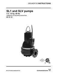
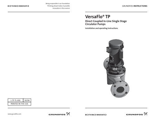
<strong>VersaFlo®</strong> <strong>TP</strong><br />
Direct Coupled In-Line Single Stage<br />
Circulator Pumps<br />
Installation and operating instructions<br />
GRUNDFOS INSTRUCTIONS
LIMITED WARRANTY<br />
Products manufactured by GRUNDFOS PUMPS CORPORATION (GRUNDFOS) are warranted<br />
to the original user only to be free of defects in material and workmanship for a period<br />
of 24 months from date of installation, but not more than 30 months from date of<br />
manufacture. GRUNDFOS' liability under this warranty shall be limited to repairing or<br />
replacing at GRUNDFOS' option, without charge, F.O.B. GRUNDFOS' factory or authorized<br />
service station, any product of GRUNDFOS manufacture. GRUNDFOS will not be liable for<br />
any costs of removal, installation, transportation, or any other charges which may arise<br />
in connection with a warranty claim. Products which are sold but not manufactured by<br />
GRUNDFOS are subject to the warranty provided by the manufacturer of said products and<br />
not by GRUNDFOS' warranty. GRUNDFOS will not be liable for damage or wear to products<br />
caused by abnormal operating conditions, accident, abuse, misuse, unauthorized alteration<br />
or repair, or if the product was not installed in accordance with GRUNDFOS' printed<br />
installation and operating instructions.<br />
To obtain service under this warranty, the defective product must be returned to the<br />
distributor or dealer of GRUNDFOS products from which it was purchased together<br />
with proof of purchase and installation date, failure date, and supporting installation<br />
data. Unless otherwise provided, the distributor or dealer will contact GRUNDFOS or<br />
an authorized service station for instructions. Any defective product to be returned to<br />
GRUNDFOS or a service station must be sent freight prepaid; documentation supporting<br />
the warranty claim and/or a Return Material Authorization must be included if so<br />
instructed.<br />
GRUNDFOS WILL NOT BE LIABLE FOR ANY INCIDENTAL OR CONSEQUENTIAL DAMAGES,<br />
LOSSES, OR EXPENSES ARISING FROM INSTALLATION, USE, OR ANY OTHER CAUSES. THERE<br />
ARE NO EXPRESS OR IMPLIED WARRANTIES, INCLUDING MERCHANTABILITY OR FITNESS<br />
FOR A PARTICULAR PURPOSE, WHICH EXTEND BEYOND THOSE WARRANTIES DESCRIBED OR<br />
REFERRED TO ABOVE.<br />
Some jurisdictions do not allow the exclusion or limitation of incidental or consequential<br />
damages and some jurisdictions do not allow limitations on how long implied warranties<br />
may last. Therefore, the above limitations or exclusions may not apply to you. This<br />
warranty gives you specific legal rights and you may also have other rights which vary from<br />
jurisdiction to jurisdiction.<br />
Please leave these instructions with the pump for future reference.<br />
U.S.A.<br />
GRUNDFOS Pumps Corporation<br />
17100 West 118th Terrace<br />
Olathe, Kansas 66061<br />
Phone: +1-913-227-3400<br />
Telefax: +1-913-227-3500<br />
Canada<br />
GRUNDFOS Canada, Inc.<br />
2941 Brighton Road<br />
Oakville, Ontario<br />
L6H 6C9<br />
Phone: +1-905-829-9533<br />
Telefax: +1-905-829-9512<br />
Mexico<br />
Bombas GRUNDFOS de Mexico S.A. de C.V.<br />
Boulevard TLC No. 15<br />
Parque Industrial Stiva Aeropuerto<br />
C.P. 66600 Apodaca, N.L. Mexico<br />
Phone: +1-52-81-8144 4000<br />
Telefax: +1-52-81-8144 4010
Notes<br />
14<br />
Contents<br />
Page<br />
1. Pre-Installation Checklist 4<br />
1.1 Confirm You Have the 4<br />
Right Pump<br />
1.2 Check the Condition of 4<br />
the Pump<br />
1.3 Electrical Requirements 4<br />
1.4 Is the Application Correct 4<br />
for This Pump?<br />
1.5 Read This Guide Thoroughly 5<br />
2. Installation Procedures 5<br />
2.1 Electrical Preparation 5<br />
2.1.1 Terminal Box Position 5<br />
2.1.2 Single-Phase Motors 5<br />
2.1.3 Three-Phase Motors 5<br />
2.1.4 Other Wiring Considerations 5<br />
2.2 Piping Considerations 5<br />
2.3 Installing the Pump 6<br />
2.3.1 Pump Location 6<br />
2.3.2 Position in Piping System 6<br />
2.3.3 Proper Orientation 6<br />
2.3.4 Direction of Flow for 6<br />
Specific Applications<br />
2.3.5 Suggested Accessories 6<br />
2.4 Electrical Hookup 6<br />
3. Starting the Pump the 6<br />
First Time<br />
3.1 Prime the Pump 6<br />
3.1.1 In Closed/Open System 6<br />
Where Water Source is<br />
Above the Pump<br />
3.1.2 In Open Systems 7<br />
3.2 Check the Direction of 7<br />
Rotation<br />
3.3 Starting and Adjusting 7<br />
4. Maintenance 7<br />
4.1 Servicing the Pump Head 7<br />
4.1.1 Step 1: Remove the Pump 7<br />
Head<br />
4.1.1.1 Assembly 8<br />
4.1.2 Step 2: Re-Install the Pump 8<br />
Head<br />
4.1.3 Motor Replacement 9<br />
4.1.3.1 Disassembly 9<br />
Page<br />
4.1.4 Pump Lubrication 9<br />
4.1.5 Motor Lubrication 9<br />
4.1.6 Lubrication Schedule 9<br />
4.1.7 Periodic Safety Checks 9<br />
4.1.8 Service Conditions 10<br />
4.1.9 Rapid Cycling 10<br />
4.1.10 Freeze Protection 10<br />
5. Troubleshooting 10<br />
5.1 Preliminary Checks 10<br />
5.1.1 Supply Voltage 10<br />
5.1.1.1 How to Measure 10<br />
5.1.1.2 Evaluation 10<br />
5.1.2 Current Measurement 10<br />
5.1.2.1 How to Measure 10<br />
5.1.2.2 Evaluation 10<br />
5.1.3 Winding Resistance 11<br />
5.1.3.1 How to Measure 11<br />
5.1.3.2 Evaluation 11<br />
5.1.4 Insulation Resistance 11<br />
(Lead to Ground)<br />
5.1.4.1 How to Measure 11<br />
5.1.4.2 Evaluation 11<br />
5.2 Diagnosing Specific Problems 12
Safety Warning<br />
Read This Booklet<br />
This booklet is designed to help a certified<br />
installer begin operation of and troubleshoot<br />
<strong>Grundfos</strong> VersaFlo <strong>TP</strong> pumps. This<br />
booklet should be left with the owner of<br />
the pump for future reference and information<br />
regarding its operation. Should the<br />
owner experience any problems with the<br />
pump, a certified professional should be<br />
contacted.<br />
Electrical Work<br />
All electrical work should be performed by<br />
a qualified electrician in accordance with<br />
the latest edition of the National Electrical<br />
Code, local codes and regulations.<br />
Shock Hazard<br />
A faulty motor or wiring can<br />
cause electrical shock that<br />
could be fatal, whether<br />
touched directly or conducted<br />
through standing water. For this reason,<br />
proper grounding of the pump to the power<br />
supply's grounding terminal is required<br />
for safe installation and operation.<br />
The ground wire should be a copper<br />
conductor at least the size of the circuit<br />
conductors supplying power to the motor.<br />
Do not ground to a gas supply line.<br />
In all installations, the above-ground metal<br />
plumbing should be connected to the<br />
power supply ground as described in Article<br />
250-80 of the National Electrical Code.<br />
1. Pre-Installation Checklist<br />
1.1 Confirm You Have the Right Pump<br />
• Read the pump nameplate to make sure<br />
that it is the correct one.<br />
• Compare the pump's nameplate data<br />
and its performance curve (for head,<br />
GPM, etc.) with the application in which<br />
you plan to install it.<br />
• Will the pump do what you expect it to<br />
do?<br />
• The nomenclature for the VersaFlo <strong>TP</strong><br />
line of <strong>Grundfos</strong> pumps is:<br />
4<br />
Circulator Pump<br />
Nominal diameter (suction<br />
& discharge) of ports in mm<br />
<strong>TP</strong> 50 80 B<br />
Bronze<br />
Maximum head in dm<br />
1.2 Check the Condition of the Pump<br />
The shipping carton your pump came in<br />
is designed around your pump during production<br />
to prevent damage. As a precaution,<br />
it should remain in the carton until<br />
you are ready to install it. At that point,<br />
look at the pump and examine it for any<br />
damage that may have occurred during<br />
shipping. Examine any other parts of the<br />
shipment as well for any visible damage.<br />
1.3 Electrical Requirements<br />
Check the motor nameplate to determine<br />
the proper voltage, phase, and frequency<br />
required. The voltage must be within ± 10%<br />
of the specified motor nameplate voltage.<br />
Dual volt-age motors must be internally<br />
wired to match the electrical supply. A<br />
wiring connection diagram is affixed to the<br />
motor.<br />
Fig. 1<br />
SPEC<br />
FRAME<br />
H.P.<br />
VOLTS<br />
AMPS<br />
R.P.M.<br />
HZ<br />
SE R F<br />
RATING<br />
CAT. NO.<br />
FULL LOAD EF F.<br />
SER<br />
PH CLASS<br />
DES CODE<br />
P. F.<br />
1.4 Is the Application Correct for This Pump?<br />
Compare the pump's nameplate data or its<br />
performance curve with the application in<br />
which you plan to install it. Will it perform<br />
the way you want it to perform? Also,<br />
make sure the application falls within the<br />
following limits:<br />
Approved applications:<br />
• Open or closed water systems<br />
• Glycol solutions up to 50% (requires<br />
optional RUVV mechanical seal)<br />
• HVAC hot and cooled water<br />
• Condenser or cooling tower heat<br />
exchanger circulation<br />
• Commercial solar<br />
• Commercial heating and fan coil<br />
systems<br />
• Geothermal systems<br />
• Agricultural temperature conditioning<br />
• Snow melting<br />
®<br />
LOW<br />
VOLTAGE<br />
HOOKUP<br />
HIGH<br />
VOLTAGE<br />
HOOKUP<br />
Nameplate<br />
Wiring<br />
Diagram<br />
(in this case, for<br />
a dual voltage<br />
motor)<br />
Correct it by...<br />
If no voltage at motor, check feeder panel for tripped circuits.<br />
Replace blown fuses or reset circuit breaker. If new fuses blow or circuit breaker trips, the terminal box wiring must be<br />
checked.<br />
Replace burned heaters or reset. Inspect starter for other damage. If heater trips again, check the supply voltage and<br />
starter holding coil.<br />
If no voltage, check the control circuit fuses. If there is voltage, check the holding coil for shorts. Replace bad coil.<br />
Replace worn or defective parts.<br />
If the motor windings are open or grounded, replace the motor.<br />
When the meter is connected, the needle should jump toward “0” ohms and slowly drift back to infinity. Replace<br />
capacitor if defective.<br />
Correct wiring and change leads as required.<br />
Refill the pump, replace lug and start the pump. Long suction lines must be filled before starting the pump.<br />
Clean and replace. Re-prime the pump.<br />
Reduce suction lift by lowering pump, increasing suction line size or by removing high friction-loss fittings.<br />
Repair all leaks and retighten all loose fittings.<br />
Convert PSI to feet (PSI x 2.31 = _____ ft.). Refer to the specific pump curve for shutoff head for that pump model. If<br />
actual head is close to curve, the pump is probably OK. If not, remove pump and inspect.<br />
Readjust switch or replace if defective.<br />
Readjust setting (refer to level control manufacturer’s data). Replace if defective.<br />
Check diaphragm for leak. Check tank and piping for leaks with soap and water solution. Check air-to-water volume.<br />
Tank volume should be approximately 10 gal. for each gpm of pump capacity. The normal air volume is 2/3 of the total<br />
tank volume at the pump cut-in pressure.<br />
If voltage varies more than ±10%, contact power company. Check wire sizing.<br />
Increase heater size or adjust trip setting.<br />
Must be within ±5%. If not, check motor and wiring.<br />
If an open or grounded winding is found, repair or replace the motor.<br />
Tighten loose terminals. Replace damaged wire.<br />
If shaft does not rotate, remove pump and inspect. Disassemble and repair.<br />
When the ohmmeter is connected to the capacitor, the needle should jump towards “0” ohms and slowly drift back to<br />
infinity; or, with the capacitor meter the UF reading should be ±10% of capacitor rating. Replace if defective.<br />
13
5.2 Diagnosing Specific Problems<br />
12<br />
If the pump... It may be caused by... Check this by...<br />
Does not run<br />
Pump runs, but at<br />
a reduced capacity<br />
or<br />
Doesn’t deliver<br />
water<br />
Pump cycles too<br />
much<br />
Fuses blow<br />
or<br />
Circuit breakers<br />
trip<br />
1. No power at motor. Check for voltage at terminal box.<br />
2. Fuses are blown or circuit<br />
breakers are tripped.<br />
3. Motor starter overloads are<br />
burned or have tripped.<br />
Turn off power and remove fuses and check for<br />
continuity with an ohmmeter.<br />
Check for voltage on the line and load side of the starter.<br />
4. Starter does not energize. Energize control circuit and check for voltage at the<br />
holding coil.<br />
5. Defective controls. Check all safety and pressure switches for operation.<br />
Inspect contact in control devices.<br />
6. Motor is defective. Turn off power. Disconnect the wiring. Measure the<br />
lead-to-lead resistance with an ohmmeter (set at R x 1).<br />
Measure lead-to-ground values with a megohmmeter<br />
(R x 100K). Record the measured values.<br />
7. Defective capacitor.<br />
(Single-phase motors)<br />
1. Wrong rotation<br />
(Three-phase only)<br />
2. Pump is not primed or is airbound.<br />
3. Strainers, check valves, or foot<br />
valves are clogged.<br />
Turn off the power, then discharge the capacitor.<br />
Disconnect the leads and check them with an ohmmeter<br />
(R x 100K).<br />
Check for proper electrical connections in terminal box.<br />
Turn pump off, close isolation valves, remove priming<br />
plug. Check fluid level.<br />
Remove strainer, screen, or valve and inspect.<br />
4. Suction lift too large. Install compound pressure gauge at the suction side<br />
of the pump. Start pump and compare reading to<br />
performance data.<br />
5. Suction and/or discharge piping<br />
leaks.<br />
Pump shaft spins backwards when turned off. Air in<br />
suction pipe.<br />
6. Worn pump. Install pressure gauge, start the pump, gradually close<br />
the discharge valve and read pressure at shut-off.<br />
1. Pressure switch is not properly<br />
adjusted or is defective.<br />
2. Level control is not properly set<br />
or is defective.<br />
3. Three-phase current is unbalanced.<br />
Check pressure setting on switch and operation.<br />
Check voltage across closed contacts.<br />
Check setting and operation.<br />
4. Tank is too small. Pump air into tank or diaphragm chamber. Check tank<br />
size and air volume in tank.<br />
1. High or low voltage. Check voltage at the starter panel or terminal box.<br />
2. Starter overloads are set too low. Cycle pump and measure amperage.<br />
3. Three-phase current is unbalanced.<br />
Check the current draw on each lead to the motor.<br />
4. Motor is shorted or grounded Turn off power and disconnect incoming power supply<br />
from terminal box. Measure winding and lead-to-ground<br />
resistance as explained on the previous page.<br />
5. Wiring or connections are faulty. Check for proper wiring and loose terminals.<br />
6. Pump is stuck. Turn off power and manually rotate pump shaft.<br />
7. Defective capacitor.<br />
(Single-phase only)<br />
Turn off power, discharge capacitor and check with<br />
ohmmeter set at highest R value or check with capacitor<br />
meter.<br />
Temperature range<br />
• Minimum +5°F (-15°C)<br />
• Maximum +284°F (140°C)<br />
Maximum working pressure:<br />
145 PSI (10 bars)<br />
1.5 Read This Guide Thoroughly<br />
Even if you are very familiar with the<br />
installation of this pump, a quick glance<br />
through the remaining sections of this<br />
guide may help you avoid a potential<br />
problem.<br />
For <strong>TP</strong>E pump installation, see <strong>Grundfos</strong><br />
Pumps publication L-EC-TL-001.<br />
2. Installation Procedures<br />
2.1 Electrical Preparation<br />
2.1.1 Terminal Box Position<br />
Before installing the pump, you must determine<br />
the most convenient position for<br />
the terminal box, which can be rotated in<br />
90° increments. To rotate the terminal box,<br />
remove the four bolts securing the motor<br />
to the pump, lift and rotate the motor, and<br />
retighten the bolts. (See page 9.)<br />
2.1.2 Single-Phase Motors<br />
Fig. 2<br />
These motors are multi-voltage with builtin<br />
automatic resetting thermal protection<br />
to prevent overheating.<br />
2.1.3 Three-Phase Motors<br />
Capacitor<br />
(single-phase only)<br />
A motor starter is required to ensure the<br />
motor is protected from damage caused by<br />
low voltage, phase failure, current imbalance,<br />
and overloads.<br />
• Motor starter — should be properly<br />
sized, have a manual reset, and ambi-<br />
ent-compensated extra quick trip in all<br />
three legs.<br />
• Overload — should be sized and adjusted<br />
to trip at the full-load current rating<br />
of the motor. If the motor is lightly<br />
loaded, the overload should be re-sized<br />
or adjusted to a lower value. Under no<br />
circumstances should the overloads be<br />
set to a higher value than the full load<br />
current shown on the motor nameplate.<br />
Overloads for auto transfers and<br />
resistant starters should be sized in<br />
accordance with the recommendations<br />
of the manufacturer.<br />
• Fused disconnect — recommended for<br />
each pump where service and standby<br />
pumps are installed. An alternating<br />
switch should be used so each pump<br />
can be equally operated to even the<br />
wear.<br />
2.1.4 Other Wiring Considerations<br />
The pump must be grounded. Wire sizes<br />
should be based on the ampacity (current<br />
carrying properties of a conductor) as required<br />
by the latest edition of the National<br />
Electrical Code or local regulations.<br />
In most cases, direct on line (D.O.L.) starting<br />
is approved due to the extremely fast<br />
run-up time of the motor and the low<br />
moment of inertia of the pump and motor.<br />
If D.O.L starting is not acceptable, an auto<br />
transformer or resistant starter should be<br />
used.<br />
2.2 Piping Considerations<br />
Whenever possible, avoid high pressureloss<br />
fittings (elbows, branch tees, etc)<br />
directly on either side of the pump. The<br />
pump and piping should be adequately<br />
supported on both sides to reduce thermal<br />
and mechanical stresses on the pump.<br />
Pipe, valves, and fittings should be at least<br />
the same diameter as the discharge pipe<br />
to reduce excessive fluid velocities and<br />
friction losses. They should also have a<br />
pressure rating equal to or greater than<br />
the maximum system pressure.<br />
A bypass or pressure relief valve should<br />
be installed in the discharge pipe if there<br />
is any possibility the pump may operate<br />
against a closed valve in the discharge line.<br />
Circulation through the pump is required<br />
to ensure adequate cooling and lubrication<br />
of the pump.<br />
5
Minimum Pumping Rates:<br />
<strong>TP</strong>32,<strong>TP</strong>40,<strong>TP</strong>50 . . . . . . . . . . . . . . . . . . . .8 GPM<br />
<strong>TP</strong>80 . . . . . . . . . . . . . . . . . . . . . . . . . . . . .12 GPM<br />
<strong>TP</strong>100 . . . . . . . . . . . . . . . . . . . . . . . . . . . 20 GPM<br />
The bypass should be routed back to a heat<br />
dissipating source or to drain, depending<br />
on the liquid being pumped and local codes.<br />
2.3 Installing the Pump<br />
2.3.1 Pump Location<br />
The pump should be installed in a dry,<br />
well-ventilated area which is not subject to<br />
freezing or large variations in temperature.<br />
The pump should never be mounted<br />
within six inches of any obstruction or hot<br />
surface.<br />
Pumps to be installed outdoors or in a<br />
dusty environment should be ordered with<br />
a totally-enclosed-fan-cooled motor (TEFC)<br />
attached to prevent motor failure.<br />
2.3.2 Position in Piping System<br />
Do not mount the pump at the highest or<br />
lowest point in the piping system.<br />
If the pump is installed at the highest point<br />
in the piping system, it may experience<br />
reduced performance and increased noise<br />
due to air trapped in the pump.<br />
If the pump is located at the lowest point<br />
in the piping system, the dirt and sediment<br />
in the system may collect inside the pump,<br />
causing premature wear to the shaft seal.<br />
2.3.3 Proper Orientation<br />
VersaFlo <strong>TP</strong> pumps can be mounted either<br />
vertically or horizontally, and all positions<br />
in between. However, the motor shaft<br />
must never fall below the horizontal plane.<br />
6<br />
Recommended<br />
X<br />
DO NOT mount motor<br />
with shaft below<br />
horizontal plane<br />
2.3.4 Direction of Flow for Specific<br />
Applications<br />
Arrows on the flanges of the pump volute<br />
show the flow direction of water through<br />
the pump.<br />
Pumps used to circulate domestic water<br />
should ALWAYS be installed in a vertical<br />
section of the circulating pipe and pump<br />
upwards, and an effective air vent should<br />
be used in the same vertical section of pipe.<br />
If the pump must be installed in a vertical<br />
pipe pumping down, an air vent should be<br />
installed at the highest point before the<br />
pump.<br />
2.3.5 Suggested Accessories<br />
Isolation valves — should be installed on<br />
each side of the pump to avoid having to<br />
drain the system if the pump needs to be<br />
cleaned or repaired.<br />
Check valve — should be installed in the<br />
discharge pipe.<br />
Plugged tee or capped pipe — should be<br />
installed in the suction line to fill the pump<br />
and pipe before start-up, especially if the<br />
system is not pressurized.<br />
Vibration isolators — should be used in<br />
noise-sensitive areas to prevent vibra-tion<br />
from being transmitted to the structure.<br />
Relief valve of bypass line — should be<br />
installed to allow sufficient water to<br />
circulate through the pump to provide<br />
adequate cooling and lubrication of the<br />
pump's bearings and seals.<br />
2.4 Electrical Hookup<br />
Turn the incoming POWER OFF and make<br />
the proper electrical connections according<br />
to the diagram on the motor and the latest<br />
edition of the National Electrical Code.<br />
Do not start the pump — even to check<br />
the direction of rotation — until it has<br />
been filled with water. The pump may be<br />
seriously damaged if it is run dry.<br />
3. Starting the Pump the First Time<br />
3.1 Prime the Pump<br />
3.1.1. In Closed/Open System Where Water<br />
Source is Above the Pump<br />
1. Close the pump isolation valves and<br />
open the air vent screw.<br />
2. Gradually open the suction isolation<br />
valve until a steady stream of airless<br />
water runs out the air vent hole.<br />
Fig. 7<br />
1. Burned contacts on motor starter.<br />
2. Loose terminals in starter/terminal box<br />
or possible wire defect.<br />
3. Too high or too low supply voltage.<br />
4. Motor windings are shorted or<br />
grounded. Check winding and insulation<br />
resistances.<br />
5. Pump is damaged causing a motor<br />
overload.<br />
5.1.3 Winding Resistance<br />
5.1.3.1 How to Measure<br />
Turn off power and disconnect the<br />
supply power leads in the pump terminal<br />
box. Using an ohmmeter, set the scale<br />
selector to R x 1 and zero adjust the meter<br />
by touching the two ohmmeter leads<br />
together.<br />
Touch the leads of the ohmmeter to two<br />
motor leads.<br />
Fig. 8<br />
Single phase motors - touching the leads<br />
of the ohmmeter to the two outgoing "hot"<br />
motor leads (either a single motor lead or<br />
combination of leads joined together) will<br />
measure the main winding's resistance.<br />
Three phase motors - touching the leads<br />
of the ohmmeter to any two hot leads will<br />
measure that winding's resistance. Repeat<br />
for all three possible lead combinations (L1<br />
and L2, L2 and L3, L1 and L3).<br />
5.1.3.2 Evaluation<br />
If all ohm values are normal, the motor<br />
windings are neither shorted nor open.<br />
If any one ohm value is less than normal<br />
(-25%), that motor winding may be starting<br />
too short. If any one ohm value is greater<br />
than normal (+25%), the winding may<br />
be starting too open. If some values are<br />
high and some are low, the leads may be<br />
connected incorrectly, or they may have a<br />
break in the insulating jacket.<br />
5.1.4 Insulation Resistance (Lead to<br />
Ground)<br />
5.1.4.1 How to Measure<br />
Turn off power and disconnect the supply<br />
power leads in the pump terminal box.<br />
Using an ohmmeter, set the scale selector<br />
to R x 100 and zero adjust the meter<br />
by touching the two ohmmeter leads<br />
together. Touch one ohmmeter lead to a<br />
motor lead and one to ground. Repeat for<br />
each lead.<br />
5.1.4.2 Evaluation<br />
Fig. 9<br />
The resistance values for new motors must<br />
exceed 1,000,000 ohms. If they do not,<br />
replace the motor.<br />
11
4.1.8 Service Conditions<br />
Severity of<br />
Service<br />
If the pump fails to operate or there<br />
is a loss of performance, refer to the<br />
Troubleshooting section on pages 11<br />
through 14.<br />
4.1.9 Rapid Cycling<br />
Pump cycling should be monitored to<br />
make sure the pump is not starting more<br />
than 20 times per hour. If it is, premature<br />
motor failure is quite likely, due to the<br />
increased heat build-up in the motor. Make<br />
any adjustments to controls ne-cessary to<br />
reduce the frequency of stops and starts.<br />
4.1.10 Freeze Protection<br />
If the pump is installed in an area where<br />
freezing could occur, the pump and<br />
system should be drained during freezing<br />
temperatures to avoid damage.<br />
To drain the pump, close both isolation<br />
valves and loosen the suction and discharge<br />
flanges. Allow water to flow out of<br />
the pump before reconnecting the pump<br />
to the flanges. Do not tighten the flanges<br />
completely until the pump is ready to be<br />
used again.<br />
5. Troubleshooting<br />
5.1 Preliminary Checks<br />
5.1.1 Supply Voltage<br />
10<br />
Ambient<br />
Temperature<br />
(maximum)<br />
5.1.1.1 How to Measure<br />
Use a volt meter, (set to the proper scale)<br />
measure the voltage at the pump terminal<br />
box or starter.<br />
On single-phase units, measure between<br />
power leads L1 and L2 (or L1 and N for 115<br />
volt units). On three-phase units, measure<br />
between:<br />
• Power leads L1 and L2<br />
• Power leads L2 and L3<br />
• Power leads L3 and L1<br />
Atmospheric<br />
Contamination<br />
Grease<br />
Interval<br />
(hrs.)<br />
Approved<br />
Types of Grease<br />
Standard 104°F (40°C) Clean, little corrosion 5500 Shell Dolium R<br />
Severe 122°F (50°C) Moderate dirt, corrosion 2750 Chevron SR#2<br />
Extreme >122°F (50°C)<br />
or class H ins.<br />
Severe dirt, abrasive<br />
dust, corrosion<br />
Evaluation<br />
550 Or compatible<br />
equivalent grease<br />
When the motor is under load, the voltage<br />
should be within ±10% of the nameplate<br />
voltage. Larger voltage variation may<br />
cause winding damage and indicate a poor<br />
electrical supply. The pump should not be<br />
operated until these variations have been<br />
corrected.<br />
If the voltage constantly remains high or<br />
low, the motor should be changed to the<br />
correct supply voltage.<br />
Fig. 6<br />
5.1.2 Current Measurement<br />
5.1.2.1 How to Measure<br />
Use an ammeter, (set on the proper scale)<br />
to measure the current on each power lead<br />
at the terminal box or starter.<br />
Current should be measured when the<br />
pump is oper-ating at constant discharge<br />
pressure.<br />
5.1.2.2 Evaluation<br />
If the amp draw exceeds the listed<br />
service factor amps (SFA) or if the current<br />
imbalance is greater than 5% between<br />
each leg on three-phase units, check the<br />
following:<br />
3. Tighten the air vent screw and<br />
completely open the isolation valves.<br />
3.1.2 In Open Systems<br />
1. The suction pipe and pump must be<br />
filled and vented of air before starting<br />
the pump.<br />
2. Close the discharge side isolation valve<br />
and open the air vent screw and suction<br />
valve.<br />
3. Fill the suction line through the plugged<br />
tee or capped pipe (if one is installed). If<br />
not possible, remove one of the gauge<br />
tapping plugs in the pump flanges and<br />
pour water into the hole using a funnel<br />
or hose with an adapter.<br />
All air in the pump and suction line must<br />
be purged before starting the pump.<br />
3.2 Check the Direction of Rotation<br />
a. Switch the POWER OFF.<br />
b. Check to make sure the pump has been<br />
filled and vented.<br />
c. Remove the coupling guard and rotate<br />
the pump shaft to be certain it turns<br />
freely. Replace the coupling guard.<br />
d. Verify that the<br />
electrical connections<br />
are in accordance with<br />
the wiring diagram on<br />
the motor.<br />
e. Switch the power<br />
on and observe the<br />
direction of rotation.<br />
Fig. 3<br />
Air<br />
venting<br />
screw<br />
Gauge<br />
Tapping<br />
plugs (2)<br />
CO U NTER CLO C K WISE<br />
When viewed from the motor end, the<br />
pump should rotate counter-clockwise.<br />
f. To reverse the direction of rotation,<br />
TURN OFF the power supply and<br />
complete the following which applies.<br />
• On three-phase motors, interchange<br />
any two power leads at the load<br />
side of the starter. On single-phase<br />
motors, refer to the connection<br />
diagram on the motor nameplate.<br />
Change the wiring as required.<br />
g. TURN ON the power and again check for<br />
proper motor rotation.<br />
3.3 Starting and Adjusting<br />
a. Make sure that:<br />
• The pump has been primed.<br />
• The rotation is counter-clockwise<br />
when viewed from the motor end.<br />
• The piping connections are tight and<br />
adequately supported.<br />
b. Open the suction line valve completely<br />
(if one is installed).<br />
c. Close the isolation valve in the discharge<br />
pipe. It should be opened gradually<br />
after the pump is turned on. Opening<br />
the valve too fast may result in water<br />
hammer in the discharge pipe.<br />
d. Start the pump.<br />
e. Gradually open the isolation valve in the<br />
discharge piping as explained in step c.<br />
Open the valve completely.<br />
f. Check the voltage and amperage at<br />
the motor and record them. Adjust the<br />
motor overloads if required.<br />
g. If pressure gauges have been installed,<br />
check and record the values as the pump<br />
operates.<br />
h. Check all controls for proper operation.<br />
If the pump is controlled by a pressure<br />
switch, check and adjust the cut-in and<br />
cut-out pressures. If low-water level<br />
controls are used, be sure the low-level<br />
switch is properly adjusted so the pump<br />
cannot run if the pump breaks suction.<br />
4. Maintenance<br />
4.1 Servicing the Pump Head<br />
4.1.1 Step 1: Remove the Pump Head<br />
1. Turn OFF the power to the motor.<br />
2. Close any isolation valves on either<br />
side of the pump.<br />
7
Terminal<br />
Box<br />
Motor<br />
Stool<br />
Hex<br />
Screws<br />
O-Ring<br />
Impeller<br />
3. Disconnect the electrical leads and<br />
conduit from the terminal box.<br />
4. Loosen and remove the hex bolts<br />
connecting the pump head assembly to<br />
the pump housing. Note the position<br />
of the motor terminal box relative<br />
to the pump housing.<br />
5. Remove the pump head assembly<br />
from the pump housing.<br />
6. Clean the machined surfaces in the<br />
pump housing.<br />
7. Inspect the pump housing and stainless<br />
steel ring for any damage. Check to be<br />
sure the seal ring is mounted securely in<br />
the pump housing.<br />
8. Repair or replace parts as needed.<br />
4.1.1.1 Assembly<br />
With the motor/motor stool assembly<br />
upside down as shown (fig. 5)<br />
1. Carefully pass the shaft with the<br />
rotating shaft seal and impeller through<br />
the shaft hole in the motor stool (the<br />
seal rings must not be exposed to blows<br />
or knocks).<br />
2. Fit the shaft pin in the shaft pin hole.<br />
3. Fit the coupling halves and the coupling<br />
allen bolts loosely to the pump and<br />
motor shafts so that the gaps on both<br />
sides of the coupling halves are even.<br />
4. Insert a screwdriver above the coupling,<br />
push the pump shaft towards the motor<br />
as far as possible. The pump and motor<br />
shaft should touch each other. Tighten<br />
coupling allen bolts to the following<br />
specifications:<br />
8<br />
Pump<br />
Housing<br />
M6 . . . . . . . . . . . . . . . . .9.6 ft lbs<br />
M8. . . . . . . . . . . . . . . . .22.6 ft lbs<br />
Powerhead<br />
Fig. 4 5. Clean the recess of the pump housing/<br />
pump housing, do not attempt to rotate<br />
motor stool lubricate o-ring with soapy<br />
the pump head, since doing so may<br />
water if necessary.<br />
damage the O-ring.<br />
Pump Head<br />
Stainless Steel<br />
Seal Ring<br />
(inside)<br />
6. Fit the pump head in the pump housing<br />
with the terminal box in the required<br />
position, be careful to align impeller<br />
with neck ring.<br />
7. Replace the motor stool bolts and<br />
tighten to the following specifications.<br />
M8. . . . . . . . . . . . . . . . . . . . 18.4 ft lbs<br />
M10 . . . . . . . . . . . . . . . . . . 34.7 ft lbs<br />
8. Check the shaft for free rotation and<br />
replace the coupling guards.<br />
9. The pump is now completely assembled.<br />
Fig. 5<br />
4.1.2 Step 2: Re-Install the Pump Head<br />
1. Lubricate the O-ring with soapy water.<br />
2. With the motor terminal box in the<br />
desired position, carefully place the<br />
pump head assembly into the pump<br />
housing. Be careful not to damage the<br />
impeller or mating seal ring. Once the<br />
pump head O-ring is engaged with the<br />
3. Make sure the pump head assembly is<br />
properly seated on the pump housing.<br />
DO NOT force the two together.<br />
4. Tighten two of the hex bolts opposite<br />
each other until the pump head is<br />
secure to the pump housing.<br />
5. Check to make sure the motor shaft<br />
turns freely.<br />
6. Insert and tighten the rest of the hex<br />
bolts evenly to secure the pump head<br />
assembly.<br />
Hex Bolt Torque<br />
13 mm . . . . . . . . . . . . . . 19 ft lbs<br />
17 mm . . . . . . . . . . . . . . . 35 ft lbs<br />
4.1.3 Motor Replacement<br />
If the motor is damaged due to bearing<br />
failure, or electrical failure, the following<br />
instructions detail how to remove the<br />
motor for replacement. It must be<br />
emphasized that motors used on VersaFlo<br />
<strong>TP</strong> pumps are specifically selected to our<br />
rigid specifications.<br />
Replacement motors must be of the same<br />
NEMA frame size, should be equipped with<br />
the same or better bearings and have the<br />
same service factor. Failure to follow these<br />
recommendations may result in premature<br />
motor failure.<br />
4.1.3.1 Disassembly<br />
1. Remove the coupling guard screens.<br />
2. Using the proper metric allen wrench,<br />
loosen the four cap screws in the<br />
coupling, fully remove coupling halves.<br />
3. With the correct size wrench, loosen and<br />
remove the four bolts which hold the<br />
motor to the discharge section of the<br />
pump end.<br />
4. Lift the motor straight up until the shaft<br />
is free from the coupling.<br />
4.1.4 Pump Lubrication<br />
<strong>Grundfos</strong> VersaFlo <strong>TP</strong> in-line centrifugal<br />
pumps installed in accordance with<br />
these instructions and sized for correct<br />
performance will operate efficiently and<br />
provide years of service.<br />
The pumps are lubricated by the fluid they<br />
pump, and do not require any additional<br />
lubrication. However, this also means the<br />
pump should never be operated for any<br />
prolonged periods of time without fluid<br />
flowing through the pump. The motors will<br />
require periodic lubrication as noted in the<br />
following paragraphs.<br />
4.1.5 Motor Lubrication<br />
Electric motors are prelubricated at the<br />
factory and do not require additional<br />
lubrication at start-up. Motors without<br />
external grease fittings have sealed<br />
bearings that cannot be relubricated.<br />
Motors with grease fittings should only be<br />
lubricated with approved types of grease.<br />
Do not over grease the bearings. Over<br />
greasing will cause increased bearing heat<br />
and can result in bearing/motor failure.<br />
Do not mix petroleum grease and silicon<br />
grease in motor bearings.<br />
Bearing Grease will lose its lubricating<br />
ability over time, not suddenly. The<br />
lubricating ability of the grease (over time)<br />
depends primarily on the type of grease,<br />
the size of the bearings, the speed at which<br />
the bearings operate and the severity of<br />
the operating conditions.<br />
Good results can be obtained if the<br />
following recommendations are used in<br />
your maintenance program.<br />
4.1.6 Lubrication Schedule<br />
For motor frame sizes smaller than 210TC,<br />
add 0.3 oz. (8.4g) or 0.6 in.3 (2 tsp.) at the<br />
intervals listed above.<br />
4.1.7 Periodic Safety Checks<br />
At regular intervals depending on the<br />
conditions and time of operation, the<br />
following checks should be made:<br />
1. Pump meets required performance and<br />
is operating smoothly and quietly.<br />
2. There are no leaks, particularly at the<br />
shaft seal.<br />
3. The motor is not overheating.<br />
4. Remove and clean all strainers or filters<br />
in the system.<br />
5. Verify the tripping of the motor<br />
overload protection.<br />
6. Check the operation of all controls.<br />
Check unit control cycling twice and<br />
adjust if necessary.<br />
7. If the pump is not operated for<br />
unusually long periods, the unit should<br />
be maintained in accordance with these<br />
instructions. In addition, if the pump<br />
is not drained, the pump shaft should be<br />
manually rotated or run for short<br />
periods of time at monthly intervals.<br />
9