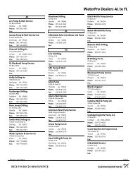
VersaFlo® TP - Grundfos
VersaFlo® TP - Grundfos
VersaFlo® TP - Grundfos

You also want an ePaper? Increase the reach of your titles
YUMPU automatically turns print PDFs into web optimized ePapers that Google loves.
Minimum Pumping Rates:<br />
<strong>TP</strong>32,<strong>TP</strong>40,<strong>TP</strong>50 . . . . . . . . . . . . . . . . . . . .8 GPM<br />
<strong>TP</strong>80 . . . . . . . . . . . . . . . . . . . . . . . . . . . . .12 GPM<br />
<strong>TP</strong>100 . . . . . . . . . . . . . . . . . . . . . . . . . . . 20 GPM<br />
The bypass should be routed back to a heat<br />
dissipating source or to drain, depending<br />
on the liquid being pumped and local codes.<br />
2.3 Installing the Pump<br />
2.3.1 Pump Location<br />
The pump should be installed in a dry,<br />
well-ventilated area which is not subject to<br />
freezing or large variations in temperature.<br />
The pump should never be mounted<br />
within six inches of any obstruction or hot<br />
surface.<br />
Pumps to be installed outdoors or in a<br />
dusty environment should be ordered with<br />
a totally-enclosed-fan-cooled motor (TEFC)<br />
attached to prevent motor failure.<br />
2.3.2 Position in Piping System<br />
Do not mount the pump at the highest or<br />
lowest point in the piping system.<br />
If the pump is installed at the highest point<br />
in the piping system, it may experience<br />
reduced performance and increased noise<br />
due to air trapped in the pump.<br />
If the pump is located at the lowest point<br />
in the piping system, the dirt and sediment<br />
in the system may collect inside the pump,<br />
causing premature wear to the shaft seal.<br />
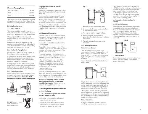
2.3.3 Proper Orientation<br />
VersaFlo <strong>TP</strong> pumps can be mounted either<br />
vertically or horizontally, and all positions<br />
in between. However, the motor shaft<br />
must never fall below the horizontal plane.<br />
6<br />
Recommended<br />
X<br />
DO NOT mount motor<br />
with shaft below<br />
horizontal plane<br />
2.3.4 Direction of Flow for Specific<br />
Applications<br />
Arrows on the flanges of the pump volute<br />
show the flow direction of water through<br />
the pump.<br />
Pumps used to circulate domestic water<br />
should ALWAYS be installed in a vertical<br />
section of the circulating pipe and pump<br />
upwards, and an effective air vent should<br />
be used in the same vertical section of pipe.<br />
If the pump must be installed in a vertical<br />
pipe pumping down, an air vent should be<br />
installed at the highest point before the<br />
pump.<br />
2.3.5 Suggested Accessories<br />
Isolation valves — should be installed on<br />
each side of the pump to avoid having to<br />
drain the system if the pump needs to be<br />
cleaned or repaired.<br />
Check valve — should be installed in the<br />
discharge pipe.<br />
Plugged tee or capped pipe — should be<br />
installed in the suction line to fill the pump<br />
and pipe before start-up, especially if the<br />
system is not pressurized.<br />
Vibration isolators — should be used in<br />
noise-sensitive areas to prevent vibra-tion<br />
from being transmitted to the structure.<br />
Relief valve of bypass line — should be<br />
installed to allow sufficient water to<br />
circulate through the pump to provide<br />
adequate cooling and lubrication of the<br />
pump's bearings and seals.<br />
2.4 Electrical Hookup<br />
Turn the incoming POWER OFF and make<br />
the proper electrical connections according<br />
to the diagram on the motor and the latest<br />
edition of the National Electrical Code.<br />
Do not start the pump — even to check<br />
the direction of rotation — until it has<br />
been filled with water. The pump may be<br />
seriously damaged if it is run dry.<br />
3. Starting the Pump the First Time<br />
3.1 Prime the Pump<br />
3.1.1. In Closed/Open System Where Water<br />
Source is Above the Pump<br />
1. Close the pump isolation valves and<br />
open the air vent screw.<br />
2. Gradually open the suction isolation<br />
valve until a steady stream of airless<br />
water runs out the air vent hole.<br />
Fig. 7<br />
1. Burned contacts on motor starter.<br />
2. Loose terminals in starter/terminal box<br />
or possible wire defect.<br />
3. Too high or too low supply voltage.<br />
4. Motor windings are shorted or<br />
grounded. Check winding and insulation<br />
resistances.<br />
5. Pump is damaged causing a motor<br />
overload.<br />
5.1.3 Winding Resistance<br />
5.1.3.1 How to Measure<br />
Turn off power and disconnect the<br />
supply power leads in the pump terminal<br />
box. Using an ohmmeter, set the scale<br />
selector to R x 1 and zero adjust the meter<br />
by touching the two ohmmeter leads<br />
together.<br />
Touch the leads of the ohmmeter to two<br />
motor leads.<br />
Fig. 8<br />
Single phase motors - touching the leads<br />
of the ohmmeter to the two outgoing "hot"<br />
motor leads (either a single motor lead or<br />
combination of leads joined together) will<br />
measure the main winding's resistance.<br />
Three phase motors - touching the leads<br />
of the ohmmeter to any two hot leads will<br />
measure that winding's resistance. Repeat<br />
for all three possible lead combinations (L1<br />
and L2, L2 and L3, L1 and L3).<br />
5.1.3.2 Evaluation<br />
If all ohm values are normal, the motor<br />
windings are neither shorted nor open.<br />
If any one ohm value is less than normal<br />
(-25%), that motor winding may be starting<br />
too short. If any one ohm value is greater<br />
than normal (+25%), the winding may<br />
be starting too open. If some values are<br />
high and some are low, the leads may be<br />
connected incorrectly, or they may have a<br />
break in the insulating jacket.<br />
5.1.4 Insulation Resistance (Lead to<br />
Ground)<br />
5.1.4.1 How to Measure<br />
Turn off power and disconnect the supply<br />
power leads in the pump terminal box.<br />
Using an ohmmeter, set the scale selector<br />
to R x 100 and zero adjust the meter<br />
by touching the two ohmmeter leads<br />
together. Touch one ohmmeter lead to a<br />
motor lead and one to ground. Repeat for<br />
each lead.<br />
5.1.4.2 Evaluation<br />
Fig. 9<br />
The resistance values for new motors must<br />
exceed 1,000,000 ohms. If they do not,<br />
replace the motor.<br />
11