VersaFlo® TP - Grundfos
VersaFlo® TP - Grundfos
VersaFlo® TP - Grundfos

Create successful ePaper yourself
Turn your PDF publications into a flip-book with our unique Google optimized e-Paper software.
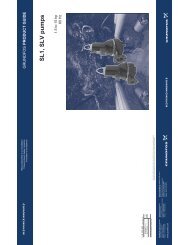
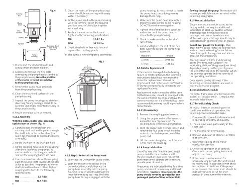
Terminal<br />
Box<br />
Motor<br />
Stool<br />
Hex<br />
Screws<br />
O-Ring<br />
Impeller<br />
3. Disconnect the electrical leads and<br />
conduit from the terminal box.<br />
4. Loosen and remove the hex bolts<br />
connecting the pump head assembly to<br />
the pump housing. Note the position<br />
of the motor terminal box relative<br />
to the pump housing.<br />
5. Remove the pump head assembly<br />
from the pump housing.<br />
6. Clean the machined surfaces in the<br />
pump housing.<br />
7. Inspect the pump housing and stainless<br />
steel ring for any damage. Check to be<br />
sure the seal ring is mounted securely in<br />
the pump housing.<br />
8. Repair or replace parts as needed.<br />
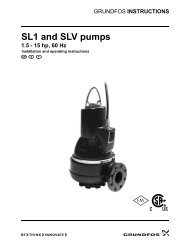
4.1.1.1 Assembly<br />
With the motor/motor stool assembly<br />
upside down as shown (fig. 5)<br />
1. Carefully pass the shaft with the<br />
rotating shaft seal and impeller through<br />
the shaft hole in the motor stool (the<br />
seal rings must not be exposed to blows<br />
or knocks).<br />
2. Fit the shaft pin in the shaft pin hole.<br />
3. Fit the coupling halves and the coupling<br />
allen bolts loosely to the pump and<br />
motor shafts so that the gaps on both<br />
sides of the coupling halves are even.<br />
4. Insert a screwdriver above the coupling,<br />
push the pump shaft towards the motor<br />
as far as possible. The pump and motor<br />
shaft should touch each other. Tighten<br />
coupling allen bolts to the following<br />
specifications:<br />
8<br />
Pump<br />
Housing<br />
M6 . . . . . . . . . . . . . . . . .9.6 ft lbs<br />
M8. . . . . . . . . . . . . . . . .22.6 ft lbs<br />
Powerhead<br />
Fig. 4 5. Clean the recess of the pump housing/<br />
pump housing, do not attempt to rotate<br />
motor stool lubricate o-ring with soapy<br />
the pump head, since doing so may<br />
water if necessary.<br />
damage the O-ring.<br />
Pump Head<br />
Stainless Steel<br />
Seal Ring<br />
(inside)<br />
6. Fit the pump head in the pump housing<br />
with the terminal box in the required<br />
position, be careful to align impeller<br />
with neck ring.<br />
7. Replace the motor stool bolts and<br />
tighten to the following specifications.<br />
M8. . . . . . . . . . . . . . . . . . . . 18.4 ft lbs<br />
M10 . . . . . . . . . . . . . . . . . . 34.7 ft lbs<br />
8. Check the shaft for free rotation and<br />
replace the coupling guards.<br />
9. The pump is now completely assembled.<br />
Fig. 5<br />
4.1.2 Step 2: Re-Install the Pump Head<br />
1. Lubricate the O-ring with soapy water.<br />
2. With the motor terminal box in the<br />
desired position, carefully place the<br />
pump head assembly into the pump<br />
housing. Be careful not to damage the<br />
impeller or mating seal ring. Once the<br />
pump head O-ring is engaged with the<br />
3. Make sure the pump head assembly is<br />
properly seated on the pump housing.<br />
DO NOT force the two together.<br />
4. Tighten two of the hex bolts opposite<br />
each other until the pump head is<br />
secure to the pump housing.<br />
5. Check to make sure the motor shaft<br />
turns freely.<br />
6. Insert and tighten the rest of the hex<br />
bolts evenly to secure the pump head<br />
assembly.<br />
Hex Bolt Torque<br />
13 mm . . . . . . . . . . . . . . 19 ft lbs<br />
17 mm . . . . . . . . . . . . . . . 35 ft lbs<br />
4.1.3 Motor Replacement<br />
If the motor is damaged due to bearing<br />
failure, or electrical failure, the following<br />
instructions detail how to remove the<br />
motor for replacement. It must be<br />
emphasized that motors used on VersaFlo<br />
<strong>TP</strong> pumps are specifically selected to our<br />
rigid specifications.<br />
Replacement motors must be of the same<br />
NEMA frame size, should be equipped with<br />
the same or better bearings and have the<br />
same service factor. Failure to follow these<br />
recommendations may result in premature<br />
motor failure.<br />
4.1.3.1 Disassembly<br />
1. Remove the coupling guard screens.<br />
2. Using the proper metric allen wrench,<br />
loosen the four cap screws in the<br />
coupling, fully remove coupling halves.<br />
3. With the correct size wrench, loosen and<br />
remove the four bolts which hold the<br />
motor to the discharge section of the<br />
pump end.<br />
4. Lift the motor straight up until the shaft<br />
is free from the coupling.<br />
4.1.4 Pump Lubrication<br />
<strong>Grundfos</strong> VersaFlo <strong>TP</strong> in-line centrifugal<br />
pumps installed in accordance with<br />
these instructions and sized for correct<br />
performance will operate efficiently and<br />
provide years of service.<br />
The pumps are lubricated by the fluid they<br />
pump, and do not require any additional<br />
lubrication. However, this also means the<br />
pump should never be operated for any<br />
prolonged periods of time without fluid<br />
flowing through the pump. The motors will<br />
require periodic lubrication as noted in the<br />
following paragraphs.<br />
4.1.5 Motor Lubrication<br />
Electric motors are prelubricated at the<br />
factory and do not require additional<br />
lubrication at start-up. Motors without<br />
external grease fittings have sealed<br />
bearings that cannot be relubricated.<br />
Motors with grease fittings should only be<br />
lubricated with approved types of grease.<br />
Do not over grease the bearings. Over<br />
greasing will cause increased bearing heat<br />
and can result in bearing/motor failure.<br />
Do not mix petroleum grease and silicon<br />
grease in motor bearings.<br />
Bearing Grease will lose its lubricating<br />
ability over time, not suddenly. The<br />
lubricating ability of the grease (over time)<br />
depends primarily on the type of grease,<br />
the size of the bearings, the speed at which<br />
the bearings operate and the severity of<br />
the operating conditions.<br />
Good results can be obtained if the<br />
following recommendations are used in<br />
your maintenance program.<br />
4.1.6 Lubrication Schedule<br />
For motor frame sizes smaller than 210TC,<br />
add 0.3 oz. (8.4g) or 0.6 in.3 (2 tsp.) at the<br />
intervals listed above.<br />
4.1.7 Periodic Safety Checks<br />
At regular intervals depending on the<br />
conditions and time of operation, the<br />
following checks should be made:<br />
1. Pump meets required performance and<br />
is operating smoothly and quietly.<br />
2. There are no leaks, particularly at the<br />
shaft seal.<br />
3. The motor is not overheating.<br />
4. Remove and clean all strainers or filters<br />
in the system.<br />
5. Verify the tripping of the motor<br />
overload protection.<br />
6. Check the operation of all controls.<br />
Check unit control cycling twice and<br />
adjust if necessary.<br />
7. If the pump is not operated for<br />
unusually long periods, the unit should<br />
be maintained in accordance with these<br />
instructions. In addition, if the pump<br />
is not drained, the pump shaft should be<br />
manually rotated or run for short<br />
periods of time at monthly intervals.<br />
9