xWrong - Biolase
xWrong - Biolase
xWrong - Biolase

Create successful ePaper yourself
Turn your PDF publications into a flip-book with our unique Google optimized e-Paper software.
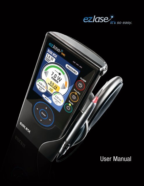
so easy.<br />
User Manual
CONTENTS<br />
INTRODUCTION . . . . . . . . . . . . . . . . . . . . . . . . . . . 3<br />
Section 1 INSTALLATION . . . . . . . . . . . . . . . . . . . . . . . . . . . . . 4<br />
Installation Instructions . . . . . . . . . . . . . . . . . . . . . . . 4<br />
Facility Requirements . . . . . . . . . . . . . . . . . . . . . . . . 4<br />
Electrical Supply . . . . . . . . . . . . . . . . . . . . . . . . . . 4<br />
Environmental Requirements . . . . . . . . . . . . . . . . 4<br />
Section 2 SAFETY . . . . . . . . . . . . . . . . . . . . . . . . . . . . . . . . . . 5<br />
Precautions . . . . . . . . . . . . . . . . . . . . . . . . . . . . . . . . 5<br />
Safety Instructions . . . . . . . . . . . . . . . . . . . . . . . . . . 5<br />
Safety Features . . . . . . . . . . . . . . . . . . . . . . . . . . . . . 6<br />
Energy Monitor . . . . . . . . . . . . . . . . . . . . . . . . . . . 6<br />
System Monitor . . . . . . . . . . . . . . . . . . . . . . . . . . . 7<br />
Power Switch . . . . . . . . . . . . . . . . . . . . . . . . . . . . 7<br />
Key Access . . . . . . . . . . . . . . . . . . . . . . . . . . . . . . 7<br />
READY Button . . . . . . . . . . . . . . . . . . . . . . . . . . . 8<br />
Footswitch . . . . . . . . . . . . . . . . . . . . . . . . . . . . . . . 8<br />
Remote Interlock . . . . . . . . . . . . . . . . . . . . . . . . . . 9<br />
Emergency Stop . . . . . . . . . . . . . . . . . . . . . . . . . . 9<br />
Functional Display . . . . . . . . . . . . . . . . . . . . . . . . . 9<br />
Safety Classification . . . . . . . . . . . . . . . . . . . . . . . . . 9<br />
Section 3 EQUIPMENT DESCRIPTION . . . . . . . . . . . . . . . . . 10<br />
General . . . . . . . . . . . . . . . . . . . . . . . . . . . . . . . . . . 10<br />
Console . . . . . . . . . . . . . . . . . . . . . . . . . . . . . . . . . . 10<br />
Surgical Delivery System . . . . . . . . . . . . . . . . . . . . 10<br />
ezlase Surgical Handpiece Assembly . . . . . . . 10<br />
ezlase Single-use Tips . . . . . . . . . . . . . . . . . . . 16<br />
Tip Initiation . . . . . . . . . . . . . . . . . . . . . . . . . . . . . . 16<br />
ezlase Whitening Handpiece . . . . . . . . . . . . . . . . . 17<br />
5400003 REV . R (12/10)
Section 4 OPERATING INSTRUCTIONS . . . . . . . . . . . . . . . . 19<br />
System Setup . . . . . . . . . . . . . . . . . . . . . . . . . . . . . 19<br />
Optional Spool Holder Installation . . . . . . . . . . . . . 20<br />
Operation . . . . . . . . . . . . . . . . . . . . . . . . . . . . . . . . 21<br />
Turn ON the ezlase . . . . . . . . . . . . . . . . . . . . . . 21<br />
ON/OFF Button . . . . . . . . . . . . . . . . . . . . . . . . . . 22<br />
READY/STANDBY Buttons . . . . . . . . . . . . . . . . . .22<br />
Navigation Wheel . . . . . . . . . . . . . . . . . . . . . . . . .22<br />
Footswitch . . . . . . . . . . . . . . . . . . . . . . . . . . . . . . .23<br />
POWER Buttons . . . . . . . . . . . . . . . . . . . . . . . . . 24<br />
Average Power Display . . . . . . . . . . . . . . . . . . . . 24<br />
LASER MODE Button . . . . . . . . . . . . . . . . . . . . . 24<br />
ENERGY Button . . . . . . . . . . . . . . . . . . . . . . . . . 25<br />
PULSE LENGTH Button . . . . . . . . . . . . . . . . . . . 25<br />
PULSE INTERVAL Button . . . . . . . . . . . . . . . . . . 25<br />
PROCEDURES Button . . . . . . . . . . . . . . . . . . . . 26<br />
MENU Button . . . . . . . . . . . . . . . . . . . . . . . . . . . 27<br />
Turn the Unit OFF . . . . . . . . . . . . . . . . . . . . . . . . . . 27<br />
Section 5 SPECIFICATIONS . . . . . . . . . . . . . . . . . . . . . . . . . 28<br />
General . . . . . . . . . . . . . . . . . . . . . . . . . . . . . . . . . . 28<br />
Electrical . . . . . . . . . . . . . . . . . . . . . . . . . . . . . . . . . 28<br />
Laser . . . . . . . . . . . . . . . . . . . . . . . . . . . . . . . . . . . . 28<br />
Other Light Sources . . . . . . . . . . . . . . . . . . . . . . . 29<br />
Section 6 CONTRAINDICATIONS, WARNINGS<br />
AND PRECAUTIONS . . . . . . . . . . . . . . . . . . . . . . . 30<br />
Contraindications . . . . . . . . . . . . . . . . . . . . . . . . . . 30<br />
Warnings and Precautions . . . . . . . . . . . . . . . . . . . 30<br />
Prescription Statement . . . . . . . . . . . . . . . . . . . . 30<br />
Eyewear . . . . . . . . . . . . . . . . . . . . . . . . . . . . . . . . 30<br />
Anesthesia . . . . . . . . . . . . . . . . . . . . . . . . . . . . . . 30<br />
Adjacent Structures . . . . . . . . . . . . . . . . . . . . . . 30<br />
Suction . . . . . . . . . . . . . . . . . . . . . . . . . . . . . . . . 31<br />
Plume Removal . . . . . . . . . . . . . . . . . . . . . . . . . . 31<br />
1
2 5400003 REV . R (12/10)<br />
Clinical Use . . . . . . . . . . . . . . . . . . . . . . . . . . . . . 31<br />
Training . . . . . . . . . . . . . . . . . . . . . . . . . . . . . . . . 31<br />
Section 7 CLINICAL APPLICATIONS . . . . . . . . . . . . . . . . . . 32<br />
Introduction . . . . . . . . . . . . . . . . . . . . . . . . . . . . . . . 32<br />
Table of Indications for Use . . . . . . . . . . . . . . . . . . . 32<br />
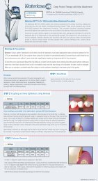
Whitening System Procedure . . . . . . . . . . . . . . . . . 34<br />
Pain Therapy Procedure . . . . . . . . . . . . . . . . . . . . . 35<br />
Recommended Pre-sets . . . . . . . . . . . . . . . . . . . . . 36<br />
Section 8 MAINTENANCE . . . . . . . . . . . . . . . . . . . . . . . . . . . 38<br />
Annual Maintenance . . . . . . . . . . . . . . . . . . . . . . . . 38<br />
Daily Maintenance . . . . . . . . . . . . . . . . . . . . . . . . . . 38<br />
Contamination Control Procedures . . . . . . . . . . . . . . . 38<br />
Cleaning Instructions for Handpiece<br />
and Fiber Optic Cable . . . . . . . . . . . . . . . . . . . . . 39<br />
Steam Sterilization for Handpiece<br />
and Single Use Tips . . . . . . . . . . . . . . . . . . . . . . 39<br />
Cleaning the ezlase Whitening Handpiece . . . . 40<br />
Transportation . . . . . . . . . . . . . . . . . . . . . . . . . . . . . 40<br />
Storage . . . . . . . . . . . . . . . . . . . . . . . . . . . . . . . . . . 41<br />
Section 9 CALIBRATION . . . . . . . . . . . . . . . . . . . . . . . . . . . . 41<br />
Calibration Schedule . . . . . . . . . . . . . . . . . . . . . . . . 41<br />
Section 10 SOFTWARE SPECIFICATION . . . . . . . . . . . . . . . . 41<br />
Section 11 TROUBLESHOOTING . . . . . . . . . . . . . . . . . . . . . . 42<br />
Appendix A LABELS . . . . . . . . . . . . . . . . . . . . . . . . . . . . . . . 44<br />
B SPARE PARTS AND ACCESSORIES . . . . . . . . 46<br />
C ezlase LIMITED WARRANTY . . . . . . . . . . . . . . 47
INTRODUCTION<br />
The ezlase Dental Soft Tissue Laser is a surgical device at the cutting<br />
edge of technology, designed for a wide variety of oral soft tissue<br />
procedures . The ezlase utilizes a solid state diode as a semiconductor<br />
source of invisible infrared radiation . The energy is delivered to the<br />
treatment site via flexible fiber, connected at one end to the laser source<br />
and the other end to the handpiece . Various types of the single use tips<br />
were designed and optimized for different applications . The device is<br />
activated by means of a footswitch . The ezlase is a prescription device<br />
that is indicated for professional use by dentists and hygenists* under<br />
the supervision of a dentist . The use of this device requires proper<br />
clinical and technical training . This manual provides instructions for<br />
dental professionals that have completed the appropriate training by an<br />
authorized <strong>Biolase</strong> Laser Specialist .<br />
CANADA: This device must be installed and operated according to the<br />
guidelines of CAN/CSA-Z386-92 “Laser safety in a health care facility .”<br />
When used and maintained properly, the ezlase will prove a valuable<br />
addition to your practice . Please contact <strong>Biolase</strong> Service at (800) 321-6717<br />
for any service needs .<br />
* This refers only to states that<br />
allow hygienists to use a<br />
class II medical laser<br />
device on patients.<br />
3
SECTION 1: INSTALLATION<br />
INSTALLATION INSTRUCTIONS<br />
Upon request, your local authorized representative will unpack and<br />
install the ezlase .<br />
Refer to the Quick Start guide for step-by-step installation instructions .<br />
The ezlase system includes the following:<br />
s<br />
s<br />
s<br />
s<br />
s<br />
s<br />
s<br />
s s<br />
s<br />
s<br />
s<br />
Console<br />
Delivery System (One Handpiece, one Fiber Assembly attached to<br />
the Console)<br />
User Manual<br />
3 pairs of Laser Safety Glasses/Goggle<br />
Footswitch with cord<br />
Power Supply with Cord<br />
Remote interlock assembly<br />
Peel-off clear covers<br />
Single use tips<br />
Tip Initiation Kit (940 only)<br />
Technical Training DVD<br />
1 Handpiece with box<br />
Use proper care prior to transporting the unit . Refer to section 8 in this<br />
manual for instructions .<br />
FACILITY REQUIREMENTS<br />
Electrical Supply (100-240V)<br />
s<br />
1 .5 - 3A, 50/60Hz<br />
Environmental Requirements<br />
s<br />
s<br />
Temperature: 20-25 ºC<br />
Humidity: 15-95%<br />
4 5400003 REV . R (12/10)
SECTION 2: SAFETY<br />
PRECAUTIONS<br />
Failure to comply with precautions and warnings described herein may lead<br />
to exposure to dangerous optical radiation sources . Please comply with all<br />
safety instructions and warnings .<br />
n CAUTION: Federal law restricts this device to sale by or under the<br />
order of a dentist or physician or other licensed practitioner .<br />
n CAUTION: Use of controls or adjustments or performance of<br />
procedures other than those specified herein may result in hazardous<br />
radiation exposure .<br />
n DANGER: Do not use this unit if you suspect it of functioning improperly<br />
or other than described herein .<br />
n CAUTION: This unit has been designed and tested to meet the<br />
requirements of electromagnetic, electrostatic, and radio frequency<br />
interference standards . However, the possibility of electromagnetic or<br />
other interference may still exist . Relocating of the device may help to<br />
eliminate the interference .<br />
n CAUTION: Laser delivery settings entered in the standby mode will<br />
be retained in memory once the unit is put into the ready mode and<br />
will become the default settings . Always ensure that the proper laser<br />
settings are set before the ezlase product is used in a clinical setting .<br />
SAFETY INSTRUCTIONS<br />
Follow these safety instructions before and during treatments:<br />
s<br />
s<br />
All operatory entrances must be marked with an appropriate laser warning<br />
sign included with shipment .<br />
Do not operate in the presence of explosive or flammable materials .<br />
Flammable anesthetics or oxidizing gases such as nitrous oxide (N2O)<br />
and oxygen should be avoided . Solvents of adhesives and flammable<br />
solutions used for cleaning and disinfecting should be allowed to<br />
evaporate before laser is used . Attention should also be drawn to the<br />
danger of ignition of endogenous gases .<br />
5
s<br />
All persons present in the operatory must wear protective laser<br />
eyewear .<br />
n CAUTION: Periodically inspect laser eyewear for pitting and<br />
cracking .<br />
n NOTE: For replacement or additional protective laser eyewear, please<br />
contact your authorized dealer .<br />
s<br />
s<br />
s<br />
s<br />
s<br />
Do not look directly into the beam or at specular reflections .<br />
Never direct or point the beam at anyone’s eyes .<br />
Press STANDBY (Standby button) on the control panel before turning<br />
off unit .<br />
Always press STANDBY on the control panel before exchanging<br />
handpieces or disposable tips .<br />
Move the toggle switch (located on rear panel) to OFF position before<br />
leaving unit unattended .<br />
n DANGER: Do not open unit housing at anytime . Danger from optical<br />
radiation may exist .<br />
n WARNING: Be aware that the metal / plastic cannula on the tips may<br />
become hot during use . Avoid contact of the cannula with any tissue .<br />
n WARNING: Do not aim the laser at metallic or reflective surfaces, such<br />
as surgical instruments or dental mirrors . If aimed directly at these<br />
surfaces, the laser beam will reflect and create a potential hazard .<br />
SAFETY FEATURES<br />
Energy Monitor<br />
The current monitor measures and verifies power output . Power<br />
deviations of more than ± 20% from the selected value will cause the<br />
display to show the error message: “DIODE CALIBRATION” .<br />
6 5400003 REV . R (12/10)
The unit will not operate until the system is reset by pressing any key on<br />
the keypad . If the error messages persist, please contact <strong>Biolase</strong> Service at<br />
1-800-321-6717 .<br />
System Monitor<br />
The system monitors emergency stop switch, remote key, footswitch<br />
connection or attachment, and output power . An error in any one of<br />
these will stop the system . The text display will indicate the type of error .<br />
Operation will not resume until the error is cleared .<br />
Power Switch<br />
The unit can be switched ON or OFF using toggle switch at the back panel .<br />
Figure 1: Power Switch<br />
n CAUTION: Use only the Power Module supplied with the ezlase system<br />
(BIOLASE part number 6400005) .<br />
Key Access<br />
ON<br />
OFF<br />
Figure 2: Power Supply<br />
Electronic key prevents unauthorized use of the system . It is activated<br />
every time system is turned off with the Power Switch .<br />
n NOTE: Turning the laser off by pressing the ON/OFF button on the front<br />
panel does not re-set the key access . Turn Power Switch OFF only when<br />
system will not be in use for a long period of time .<br />
7
READY Button<br />
Once the power switch, key access, and ON/OFF Key are set to the ON<br />
position, the READY button on the keypad must be pressed to enable<br />
the footswitch . The aiming beam will be lit to indicate that the system is<br />
ready for use .<br />
Footswitch<br />
The ezlase will not emit laser energy until the user presses down<br />
on the footswitch . The footswitch is designed to work using wireless<br />
technology . One full charge of the battery will allow approximately one<br />
week of regular operation .<br />
When the battery is low, a permanent cable should be connected to<br />
resume operation . For charging, unit must be turned ON . It takes 4<br />
hours of charging time for full battery capacity .<br />
n NOTE: It is recommended to recharge the battery overnight every week .<br />
Figure 3: Wireless Footswitch<br />
8 5400003 REV . R (12/10)<br />
Figure 4: Footswitch Cable
Remote Interlock<br />
This feature allows the device to be<br />
connected to a remote sensor which will<br />
prevent its operation when triggered (i .e .,<br />
by opening a door) . The electric cable from<br />
this connector should be wired to a normally<br />
closed switch which will turn the laser OFF when the switch is open .<br />
This feature is overridden when the plug is not connected .<br />
Emergency Stop<br />
Press the red Emergency Laser Stop button<br />
to instantly turn off the unit . Press Laser Stop<br />
button again to RESET .<br />
Functional Display<br />
The System Color TFT Display with Touch<br />
Screen and LED indicators on the control panel<br />
show the functional conditions of the system .<br />
SAFETY CLASSIFICATION<br />
The following safety classifications are<br />
applicable to the device:<br />
s<br />
s<br />
s<br />
s<br />
s<br />
s<br />
Laser Radiation – Class 4<br />
Type of protections against electrical shock<br />
– Class 1<br />
Degree of protection against electrical shock – Type B Applied Part<br />
Not protected against water ingress – Ordinary Equipment<br />
Not suitable for use in presence of flammable anesthetic mixture<br />
Operation Mode – Continuous Operation<br />
Figure 5: Remote Interlock<br />
connector<br />
Figure 6: Emergency<br />
Laser Stop<br />
9
SECTION 3: EQUIPMENT DESCRIPTION<br />
GENERAL<br />
The ezlase consists of two permanently connected components:<br />
s<br />
s<br />
Console<br />
Delivery System<br />
CONSOLE (Figures 8-12)<br />
Console has Control Panel (Touch Screen and Keypad) in front and<br />
disconnectable Base, attached at the bottom back part of the Console .<br />
SURGICAL DELIVERY SYSTEM<br />
n NOTE: All fiber optic cables, handpieces & tips are shipped non-sterile .<br />
The ezlase Delivery System with surgical handpiece consists of:<br />
s<br />
s<br />
s<br />
Fiber Optic Assembly<br />
Handpiece (Figures 13, 14)<br />
ezlase Disposable Tips (Figures 15, 16, 17)<br />
n NOTE: The fiber optic cable is permanently attached to the ezlase Console .<br />
The Handpiece is a reusable accessory . The Handpiece will require cleaning<br />
and sterilization before and after each patient treatment . Tips are intended<br />
for single-use only and should be disposed after each patient use . It is<br />
recommended to dispose of them in a sharps container . Tips should be<br />
steam sterilized prior to use . For instructions on cleaning and sterilization of<br />
the handpiece and tips, refer to Section 8 .<br />
ezlase Surgical Handpiece Assembly<br />
To disconnect handpiece from the fiber optic assembly:<br />
1 . Take the handpiece body in one hand & the shaft in another (Figure 14)<br />
2 . Push two buttons on the handpiece shaft .<br />
3 . pull handpiece with the ring to seperate .<br />
To connect the Handpiece to the Fiber optic cable, push the handpiece<br />
on the fiber shaft until it clicks on and is secured at connected position .<br />
10 5400003 REV . R (12/10)
FRONT PANEL (Figure A)<br />
Fig. 8<br />
Item# Item Item Description<br />
1 ON/OFF Turns the controls and display on and off .<br />
2 READY Allows energy delivery when footswitch is pressed .<br />
3 READY LED Indicates unit is in READY mode .<br />
4 STANDBY Does not allow energy delivery .<br />
5 STANDBY LED Indicates unit is in STANDBY mode .<br />
6 EMISSION LED Indicates emitting of the laser power .<br />
7 WIRELESS ON Indicates communication with footswitch .<br />
8 NAVIGATION WHEEL Allows to select functions and adjust parameters .<br />
6<br />
1<br />
4<br />
2<br />
8<br />
(Figure A) (Figure B)<br />
7<br />
5<br />
3<br />
MAIN MENU (Figure B)<br />
Item# Item Item Description<br />
1 AVERAGE POWER DISPLAY Indicates average power delivered .<br />
2 MAXIMUM POWER DISPLAY Indicates maximum allowable<br />
delivered power .<br />
3 POWER (up/down) Allows adjustment of delivered optical power .<br />
4 MENU Selects user function .<br />
5 PROCEDURES Selects pre-set procedure parameters .<br />
6 PULSE LENGTH (up/down) Allows adjustment of laser ON time .<br />
7 PULSE INTERVAL (up/down) Allows adjustment of laser OFF time .<br />
8 LASER MODE Allows switching and indicates laser<br />
operation mode (continuous or pulsed) .<br />
9 ENERGY DISPLAY Allows setting and displays amount of laser<br />
energy that has been delivered or to be delivered .<br />
5<br />
2<br />
9<br />
8<br />
4<br />
1<br />
3<br />
6<br />
7<br />
11
Fig. 9<br />
12 5400003 REV . R (12/10)<br />
Power Switch<br />
Emergency Stop<br />
Service Connector<br />
Remote Interlock<br />
Connector<br />
Footswitch<br />
Connector<br />
Power Connector<br />
Stand
Fig. 10<br />
Handpiece<br />
Fiber<br />
Fiber Spool<br />
13
Fig. 11<br />
14 5400003 REV . R (12/10)<br />
Regulatory Compliance and<br />
Description Labels<br />
(See Appendix A)<br />
Power Switch<br />
Fiber Outlet<br />
(located on bottom)<br />
Compliance Label
Fig. 12<br />
Control Panel<br />
Touch Screen<br />
Handpiece<br />
Handpiece Holder<br />
15
ezlase Single-Use Tips<br />
The ezlase tips are single-use accessories, which are provided in<br />
three core diameters: 200μm, 300μm, and 400μm and different lengths<br />
(Appendix B).<br />
n WARNING: DO NOT autoclave more than once.<br />
To connect the tip, insert it into the handpiece orifice and tighten by<br />
turning clockwise. Bend the metal canula according to the procedure<br />
requirements.<br />
n NOTE: To provide proper laser operation, connect tips after the handpiece is<br />
connected.<br />
n CAUTION: Do not bend tips with sharp angle - it will break the tip (Figure 17).<br />
If the red aiming beam is not present in READY mode - replace the tip.<br />
TIP INITIATION: ezlase 940 parameters and procedures<br />
n LASER PARAMETERS:<br />
n PROCEDURAL STEPS:<br />
n SUGGESTIONS: Do not push the tip into the block surface . Allow it to sink in<br />
with its own weight . Steps above may be repeated on the same tip if the initiation<br />
is lost .<br />
Step 3) Fire the<br />
laser, allowing the<br />
tip to sink into the<br />
block. Pull the tip<br />
out when the metal<br />
canula touches the<br />
block, still firing until<br />
just before the tip is<br />
out of the block.<br />
16 5400003 REV . R (12/10)<br />
Tip Diameter (mm) Power (W) Mode<br />
400 1.4 CW<br />
300 1.0 CW<br />
Step 1) Set the<br />
ezlase to the<br />
appropriate setting<br />
for the particular<br />
tip, using the table<br />
above as a guide.<br />
Step 2) Touch<br />
the ezlase tip<br />
to the surface<br />
of the initiation<br />
block, without<br />
firing.<br />
Step 4) Fire the laser into the air once, you<br />
will see a white flash or the tip will glow.<br />
Repeat Steps 1 - 4 to ensure the tip<br />
is initiated.
ezlase Whitening Handpiece (Optional)<br />
n NOTE: The Handpiece is reusable and equipped with a disposable non-sterile<br />
protective cover for single patient use. The handpiece requires cleaning before and<br />
after each patient treatment. For instructions on cleaning the handpiece, refer to<br />
section 8.<br />
ezlase Whitening Handpiece<br />
LaserWhite 20 Disposable Shield<br />
The area of Laser Energy Output is 35mm x 8mm = 2 .8 cm 2 Spot Size .<br />
To disconnect the handpiece from the fiber optic assembly:<br />
1. Take the handpiece body in one hand & the shaft in another [ Figure 13 ].<br />
2. Push two buttons on the handpiece shaft.<br />
3. Pull handpiece with the ring to separate.<br />
To connect the Handpiece to the Fiber optic cable, push the handpiece<br />
on the fiber shaft until it clicks on and is secured.<br />
17
Figure 13: ezlase Handpiece Assembly<br />
Fiber Shaft<br />
Figure 14: Disconnecting the Handpiece (push both buttons)<br />
Tip Assembly<br />
Figure 15: Disconnecting the fiber Tip (twist first counter clockwise)<br />
Figure 16: Tightening the fiber tips twist (only when Handpiece is connected to fiber)<br />
x<br />
Bend<br />
Right<br />
Wrong<br />
Figure 17: Bending the tip canula<br />
Handpiece<br />
Protective Window<br />
18 5400003 REV . R (12/10) 18
SECTION 4: OPERATING INSTRUCTIONS<br />
SYSTEM SETUP<br />
s<br />
s<br />
s<br />
Place unit in a clean, dry and well ventilated area .<br />
Verify power switch is in OFF position<br />
Connect power cord to power connector on the unit and plug into<br />
wall outlet .<br />
n CAUTION: Do not cover or block ventilation channels . These<br />
channels provide air-flow path to cool unit .<br />
n CAUTION: Do not bend fiber optic cable sharply or the fiber will break .<br />
s<br />
s<br />
s<br />
s<br />
s<br />
s<br />
Remove protective tip plug and handpiece from fiber shaft<br />
Verify visually that protective window is clean . If not – blow off any<br />
residue or dirt with compressed air . For better results use cotton<br />
swab moistened with alcohol .<br />
Carefully connect the Handpiece (Figure 13)<br />
Insert the selected tip and tighten it clockwise until snug .<br />
Wind excess fiber optic cable on to fiber spool (clockwise) .<br />
Place handpiece in handpiece holder . (Figure 12)<br />
n CAUTION: Tips are designed for single patient use only . Use a new<br />
tip each time ezlase is used .<br />
n WARNING: Never point the fiber optic at the eyes .<br />
n WARNING: Never operate the laser without a fiber tip attached .<br />
n WARNING: All persons present in the operatory MUST wear<br />
protective laser eyewear when laser is in operation .<br />
19
OPTIONAL SPOOL HOLDER INSTALLATION<br />
s<br />
s<br />
s<br />
Slide Spool Holder into the rear of the ezlase.<br />
Route fiber cable through the bottom of the Spool Holder .<br />
Spool the fiber cable in a clockwise direction in Spool Holder .<br />
20 5400003 REV . R (12/10)
OPERATION<br />
Turn ON the ezlase <br />
s<br />
s<br />
s<br />
s<br />
s<br />
s<br />
s<br />
Connect power cord to power connector on the unit and plug into<br />
wall outlet .<br />
Connect footswitch cable to the unit and to the footswitch .<br />
Turn power switch to ON position . ezlase Welcome screen will<br />
be displayed .<br />
Enter the three digit key access code using the touch screen or<br />
system “navigation wheel” . Access Key Code is 123 .<br />
Also you can use the Right “>” arrow and “Enter” buttons on the<br />
Navigation Wheel to select the numbers<br />
System will go to the Main Menu . If code is selected wrong, re-enter<br />
the code .<br />
Disconnect and press the footswitch . Blue LEDs will light to confirm<br />
presence of wireless communication .<br />
BIOLASE<br />
Welcome to<br />
1 2 3 4<br />
5 6 7 8<br />
Fig. 18 Fig. 19<br />
21
ON/OFF Button<br />
Press ON/OFF button . At this time the unit will go to “sleep” mode or<br />
turns ON and performs self-diagnostic .<br />
READY/STANDBY Buttons<br />
Unit will only emit laser energy when footswitch is pressed and unit is<br />
set to READY mode . Values may be adjusted in both modes . In READY<br />
mode, values may be changed only when footswitch is released .<br />
Press READY button . At this time system fan will turn ON and pressing<br />
the footswitch will activate laser radiation . There is a 2 sec delay<br />
between switching to READY mode and ability of system to emit a<br />
laser beam . This is evidenced by the delay in the appearance of the red<br />
aiming beam .<br />
Navigation Wheel<br />
The Navigation Wheel can be used instead of the touch screen .<br />
General approach to navigate is:<br />
• “Up“and “Down” arrow buttons are used to scroll between functions<br />
• “Left” and “Right” arrow buttons are used to increase / decrease<br />
values<br />
• “Enter” button is used to select function or enter the value<br />
Fig. 20 Fig. 21<br />
When the tip<br />
is straight, the<br />
aiming beam<br />
will look like a<br />
circle, outlining<br />
the area<br />
where main<br />
laser power is<br />
applied .<br />
22 5400003 REV . R (12/10)<br />
When footswitch<br />
is pressed, laser<br />
power is applied<br />
and beam<br />
will fill the<br />
middle area<br />
of the spot .
Footswitch<br />
When footswitch is pressed and the laser fires, the LASER FIRING icon<br />
(---*) will flash and a beeper will sound, indicating that laser energy is<br />
present . An amber LED will be lit as well on the top of the front panel .<br />
When the footswitch is not pressed, the LASER FIRING icon will go blank,<br />
indicating that laser energy is not present .<br />
n NOTE: Charge footswitch battery for 4 hours when first connected .<br />
Power switch should be ON . Before disconnecting the footswitch cord<br />
after each charging, re-cycle power by turning power switch OFF and<br />
ON to re-set wireless communication . When the unit is on standby mode<br />
press down on footswitch and hold . Then unplug footswitch cord from<br />
the unit . While holding down the footswitch-blinking Blue LEDs confirm<br />
presence of wireless comunication . The cable can be removed from the<br />
footswitch at this point . Footswitch will operate for about 1 week without<br />
re-charge, so long as power switch is maintained in the “ON” position .<br />
If you have more than one ezlase unit in your facility, you must observe the<br />
following precautions:<br />
n WARNING: DO NOT establish wireless communication with more than<br />
one ezlase/footswitch combination simultaneously . Instead, establish<br />
wireless communication sequentially, one pair at a time . See note above<br />
for instructions on establishing wireless communication .<br />
n WARNING: DO NOT disconnect the footswitch cable at either end when<br />
the laser is firing .<br />
n WARNING: Before turning off the power switch at the rear of the ezlase<br />
device, disconnect the footswitch cable at either end . (Note that the<br />
power switch must be turned ON when charging the footswitch .)<br />
n WARNING: When aiming beam is not present or has<br />
significantly different shape than shown in Figure 20 and 21, change the<br />
tip and inspect / clean the protective window (see Section 8) .<br />
23
POWER Buttons (Figures 8 and 19)<br />
Press POWER arrows to adjust power level . Press right arrow to<br />
increase power level or press left arrow to decrease power level .<br />
Average Power Display<br />
This icon is shown only when the system is in the pulsed mode and<br />
presents the calculated value of the average power based on the Power<br />
setting, Pulse Length and Pulse Interval .<br />
LASER MODE Button<br />
LASER MODE Button graphically indicates whether system is in<br />
Continuous Mode or in Pulsed Mode . Only when the system is in<br />
Pulsed Mode, both Pulse Length and Pulse Interval active displays<br />
are present as well as Average Power window . They are not shown in<br />
Continuous Mode .<br />
In Continuous Mode laser power is constantly delivered when in Ready<br />
Mode and footswitch is activated .<br />
In Pulsed Mode, laser radiation is delivered in repetitive pulses,<br />
controlled by Pulse Length and Pulse Interval settings .<br />
One touch of the Laser MODE button will allow switching between<br />
Pulsed and Continuous Modes .<br />
Fig. 22 Fig. 23<br />
24 5400003 REV . R (12/10)
ENERGY Button (Figure 22)<br />
ENERGY function can be used when total amount of laser energy, in<br />
[Joules] (Power [Watts] x Time [Seconds]) needs to be calculated .<br />
Press the ENERGY button to enter the Energy Mode and toggle the unit<br />
between ENERGY TOTAL, ENERGY START and OFF functions .<br />
ENERGY TOTAL allows the user to pre-set the amount of laser energy to<br />
be delivered when footswitch is pressed . Laser stops when energy counts<br />
to zero and value re-sets . This way it works as a timer .<br />
For example, if 10J is entered, and laser power is set at 1W, laser will<br />
stop firing after 10 seconds .<br />
ENERGY START allows to calculate the total amount of laser energy<br />
delivered to the tissue . It can be re-set to zero from this screen or by<br />
going to Standby mode .<br />
PULSE LENGTH Button (Figure 23)<br />
While in the Pulse Mode, press PULSE LENGTH button to adjust pulse<br />
length . Press right arrow to increase pulse length and the left arrow to<br />
decrease .<br />
Laser ON time is when the actual energy is applied . Longer – generally<br />
more thermal effect, less bleeding .<br />
Press PULSE LENGTH again to exit to the Main Menu with modified<br />
setting .<br />
Press BACK to exit to the Main Menu . This action will not change any<br />
settings .<br />
PULSE INTERVAL Button (Figure 24)<br />
While in the Pulse Mode, press PULSE INTERVAL button to adjust<br />
pulse interval . Press right arrow to increase pulse interval and left<br />
arrow to decrease .<br />
Laser OFF time allows tissue cooling, generally with less thermal effect .<br />
Fig. 24<br />
25
PROCEDURES Button (Figure 25)<br />
The system has 15 pre-sets to be programmed by the dentist . All of<br />
them can be customized to your preference . Ten of the fifteen pre-sets<br />
have been labeled for specific clinical indications . Please refer to the<br />
indications for use section for review of the clinical indications .<br />
In order to customize parameters for the particular clinical procedure:<br />
s<br />
s<br />
s<br />
Adjust parameters on the main Menu<br />
Select PROCEDURES Mode<br />
Press and hold for 2 seconds the selected Procedure . Parameters<br />
will be changed and memorized for that Procedure .<br />
26 5400003 REV . R (12/10)
MENU Button (Figure 26)<br />
By pressing the MENU button, you can get access to several system settings:<br />
Aiming Beam (5 levels of brightness adjustment)<br />
Beep Sound (3 levels of sound adjustment)<br />
Service Mode – accessible only by authorized <strong>Biolase</strong> Service<br />
Representatives .<br />
s<br />
s<br />
s<br />
TURN THE UNIT OFF<br />
s<br />
Place handpiece back on handpiece holder .<br />
n CAUTION: Verify that fiber optic tubing assembly is not twisted once the<br />
handpiece is returned to the holder . The fiber may break if it is twisted .<br />
s<br />
s<br />
s<br />
Fig. 25 Fig. 26<br />
Press the ON/OFF button to turn display OFF .<br />
Switch the Power Switch to OFF position, if laser system will not be used<br />
for a long period of time .<br />
Put the fiber cable on the spool .<br />
27
SECTION 5: ezlase SPECIFICATIONS<br />
GENERAL<br />
s<br />
s<br />
Dimensions W x H x D (3 .5” x 7 .0” x 2 .5”) (8 .5 x 18 x 6cm)<br />
Weight 2 lbs . (1 .0 kg)<br />
ELECTRICAL<br />
s<br />
s<br />
s<br />
s<br />
s<br />
s<br />
Operating Voltage 100 to 240 ~ at 2A<br />
Frequency 50 / 60 Hz<br />
External Fuses None<br />
Main Control Power Switch<br />
On / Off Controls Keypad Button, Emergency Stop<br />
Remote Interruption Remote Interlock Connector<br />
LASER<br />
s<br />
s<br />
s<br />
Laser Classification IV (4)<br />
Medium GaAlAs, InGaAsP<br />
Wavelength 810 ± 15 nm or 940 ± 15 nm<br />
28 5400003 REV . R (12/10)
s<br />
s<br />
s<br />
s<br />
s<br />
s<br />
s<br />
s<br />
s<br />
s<br />
Max Output Power 7 Watts @ 940nm, 4 .5 Watts @ 810nm<br />
Power Accuracy ± 20%<br />
Power Modes Continuous, Pulse<br />
Modulation<br />
Pulse Length* 0 .06 ms - 10 sec<br />
Pulse Interval* 0 .06 ms - 10 sec<br />
Pulse Repetition Rate up to 10 KHz (for reference)<br />
Fiber Tips Diameter 200, 300, 400 µm<br />
NOHD 11 .8 meters<br />
Beam Divergence 8 – 22 degrees per side angle<br />
Fiber Cable Length 5 feet (1 .524 meters)<br />
OTHER LIGHT SOURCES<br />
s<br />
Aiming Beam Laser Diode, max 3 mW, 630-670nm, class 3B<br />
* The following ComfortPulse ® length and interval<br />
settings will result in the ranges specified:<br />
Display Range<br />
0 .05 ms<br />
0 .10 ms<br />
0 .20 ms<br />
0 .05 ms – 0 .07 ms<br />
0 .10 ms – 0 .14 ms<br />
0 .20 ms – 0 .28 ms<br />
29
SECTION 6: CONTRAINDICATIONS, WARNINGS AND PRECAUTIONS<br />
CONTRAINDICATIONS<br />
All clinical procedures performed with ezlase must be subjected to the<br />
same clinical judgment and care as with traditional techniques . Patient risk<br />
must always be considered and fully understood before clinical treatment .<br />
The clinician must completely understand the patient’s medical history prior<br />
to treatment . Exercise caution for general medical conditions that might<br />
contraindicate a local procedure . Such conditions may include allergy to<br />
local or topical anesthetics, heart disease, lung disease, bleeding disorders,<br />
sleep apnea, and immune system deficiency, or any medical conditions or<br />
medications that may contraindicate use of certain light/laser type sources<br />
associated with this device . Medical clearance from patient’s physician is<br />
advisable when doubt exists regarding treatment .<br />
WARNINGS AND PRECAUTIONS<br />
Prescription Statement<br />
Federal law restricts this device to sale by or under the order of a dentist or<br />
physician or licensed practitioner .<br />
Eyewear<br />
Doctor, patient, assistant and all others inside the operatory must wear<br />
appropriate laser eyewear protection for the diode laser wavelength of<br />
810±15 nm or 940±15 nm .<br />
Anesthesia<br />
In soft tissue cases anesthesia may not be required, patients should be<br />
closely monitored for signs of pain or discomfort at all times . If such signs<br />
are present, adjust settings, apply anesthesia or cease treatment if required .<br />
Adjacent Structures<br />
ezlase is designed to remove soft tissues . Therefore, always be aware<br />
of adjacent structures and substructures during treatments . Be extremely<br />
careful not to inadvertently penetrate or ablate underlying or adjacent<br />
tissues . Do not direct energy towards hard tissues such as tooth or bone .<br />
Exercise extreme caution when using this device in areas such as pockets,<br />
30 5400003 REV . R (12/10)
cavities or channels such as 3rd molar sockets, where critical structures (i .e .<br />
nerves, vessels) could be damaged . Do not proceed with using the laser if<br />
visibility is limited . Do not direct energy towards amalgam, gold or other metallic<br />
surfaces . Do not direct energy towards cements or other filling materials .<br />
Suction<br />
Use high-speed suction as required to maintain a clear field of vision during<br />
treatment . Do not use the ezlase if you cannot clearly see the treatment site .<br />
Plume Removal<br />
Special care must be taken to prevent infection from the laser plume<br />
generated by vaporization of virally or bacterially infected tissue . Ensure that<br />
appropriate protective equipment (including high-speed suction to remove the<br />
plume, appropriately filtered masks, and other protective equipment) is used<br />
at all times during the laser procedure .<br />
Clinical Use<br />
Use your clinical judgment to determine all aspects of treatment including but<br />
not limited to the laser treatment protocol, technique, power settings, pulse<br />
duration and interval settings, mode of operation as well as the accessories<br />
(e .g . tip type) and other procedural requirements . Always start treatment<br />
at the lowest power setting for that specific indication and increase as<br />
required . Closely observe and monitor clinical effects and use your judgment<br />
to determine clinical parameters and approach for the treatment . Make<br />
appropriate power, pulse length and interval adjustments to compensate for<br />
varying tissue compositions, density and thickness . BIOLASE assumes no<br />
responsibility for parameters, techniques, methods or results .<br />
Training<br />
Only licensed professionals who have successfully completed the ezlase <br />
in-service training provided by a <strong>Biolase</strong> Laser Specialist or Authorized<br />
Representative, and have read and understood this User Manual should use<br />
this device . BIOLASE assumes no responsibility for parameters, techniques,<br />
methods or results . Physicians must us their own clinical judgment and<br />
professionalism in determining all aspects of treatment, technique, proper<br />
power settings, interval, duration, etc .<br />
31
SECTION 7: CLINICAL APPLICATIONS<br />
INTRODUCTION<br />
To efficiently remove tissues it is important to understand the nature of<br />
the ezlase device . Please review this section carefully, practice on<br />
model tissues and attend diode laser training seminars before using<br />
this device in a clinical situation .<br />
TABLE OF INDICATIONS FOR USE<br />
Use of the ezlase device may be appropriate for the following<br />
indications for use:<br />
SPECIALTY APPLICATION<br />
Dental Excisional and incisional biopsies<br />
Soft Tissue Exposure of unerupted teeth<br />
Fibroma removal<br />
Frenectomy<br />
Frenotomy<br />
Gingival troughing for crown impressions<br />
Gingivectomy<br />
Gingivoplasty<br />
Gingival incision and excision<br />
Hemostasis<br />
Implant recovery<br />
Incision and drainage of abscess<br />
Leukoplakia<br />
Operculectomy<br />
Oral papillectomies<br />
Pulpotomy<br />
Pulpotomy as an adjunct to root canal therapy<br />
Reduction of gingival hypertrophy<br />
Soft tissue crown lengthening<br />
Treatment of canker sores, herpetic and<br />
aphthous ulcers of the oral mucosa<br />
Vestibuloplasty<br />
32 5400003 REV . R (12/10)
CAUTION: Use caution when operating above an average power of 1 .0<br />
W (pulsed or CW mode) . Closely observe tissue effects for changes in tissue<br />
color and depth of penetration and cut . For procedures performed within<br />
enclosed spaces (e .g . pockets, channels, interproximal) use caution when<br />
operating above an average power of 0 .5 W .<br />
SPECIALTY APPLICATION<br />
Periodontal Laser soft tissue curettage<br />
Procedures Laser removal of diseased, infected, inflamed and<br />
necrosed soft tissue within the periodontal pocket<br />
Sulcular debridement (removal of diseased, infected,<br />
inflamed and necrosed soft tissue in the periodontal<br />
pocket to improve clinical indices including gingival<br />
index, gingival bleeding index, probe depth,<br />
attachment loss and tooth mobility .)<br />
Whitening Light activation for bleaching materials for teeth<br />
whitening .<br />
Laser-assisted whitening/bleaching of teeth<br />
Pain Therapy Temporary relief of minor muscle and joint pain and<br />
stiffness, or muscle spasm, minor arthritis pain, or<br />
muscle spasm, minor sprains and strains; and minor<br />
muscular back pain; the temporary increase in blood<br />
circulation; the temporary relaxation of muscle .<br />
BIOLASE assumes no responsibility for parameters, techniques, methods or results.<br />
Physicians must use their own clinical judgment and professionalism in determining all<br />
aspects of treatment, technique, proper power settings, interval, duration, etc.<br />
33
TOOTH WHITENING PROCEDURE<br />
The following items are required to perform teeth whitening:<br />
s<br />
s<br />
s<br />
ezlase 940nm diode laser*<br />
Whitening Handpiece (sold separately)<br />
LaserWhite 20 Whitening Gel Kit . (sold in packs of 5)<br />
Detailed step-by-step instructions, and contraindications, precautions,<br />
and warnings for tooth whitening are provided with the LaserWhite 20<br />
Whitening Gel Kit .<br />
* Tooth whitening can only be performed with the ezlase 940nm diode laser .<br />
The ezlase 810nm diode laser has not been validated for use with the Whitening<br />
Handpiece for teeth whitening at this time .<br />
34 5400003 REV . R (12/10)
PAIN THERAPY PROCEDURE (Requires the ezlase Whitening Handpiece)<br />
The ezlase 940nm diode laser, in conjunction with the ezlase Whitening<br />
Handpiece, is designed to provide near-infrared laser energy to tissue for<br />
the purpose of elevating the temperature and providing for temporary relief<br />
of pain conditions stated with the indications for use .<br />
Affected muscles and/or joints have to be exposed to an adequate level of<br />
therapeutic energy over a short period of time to be effective . Two main<br />
therapeutic power settings are recommended for these treatments .<br />
s<br />
s<br />
P1 = 2 .75 W: place the handpiece in contact with the skin and apply<br />
laser energy for 10 minutes continuously .<br />
P2 = 5 .50 W: place the handpiece approximately 2-3mm away from<br />
the skin surface (non-contact) . Exposure time remains<br />
the same at 10 minutes continuously .<br />
Patients should be monitored for discomfort . If discomfort is reported at<br />
any time during the treatment there are several options:<br />
a) decrease the power setting to 2 .75W; or<br />
b) defocus the energy by moving the handpiece further away from the skin;<br />
or<br />
c) stop treatment .<br />
Some patients may require more than one laser application or a series<br />
of treatments before significant improvement is reported . Repeat as<br />
necessary and monitor progress of the patient's condition throughout the<br />
treatment .<br />
35
RECOMMENDED PRE-SETS<br />
n WARNING: Always use clinical judgment when selecting power, pulse<br />
length, and pulse interval parameters to ensure optimal clinical results .<br />
The recommended settings apply only to the 300 and 400 um tips .<br />
To set your ezlase system to the Pre-Set values, make the necessary<br />
changes on the main screen . Enter the Procedures menu by selecting the<br />
Procedure button . Scroll to the desired procedure name and press and<br />
hold the button for 3 seconds when the new values are saved .<br />
n NOTES:<br />
1 . These pre-sets are recommendations based on clinical feedback<br />
from experienced laser dentists .<br />
2 . 300 um tips are recommended for removing thin tissue layers . 400<br />
um tips are recommended for removing fibrous tissue .<br />
3 . Always use your clinical judgement when selecting power, pulse<br />
length and pulse interval parameters to ensure optimal clinical<br />
results . At all times observe clinical effects and adjust parameters<br />
accordingly .<br />
36 5400003 REV . R (12/10)
RECOMMENDED PRE-SETS ezlase 940<br />
Duty<br />
Cycle<br />
Pulse<br />
Length<br />
Pulse<br />
Interval<br />
Pre-set NAME Indications Power Average<br />
Power<br />
5 .0 W 1 .0 W 0 .20 ms 0 .05 ms 20%<br />
1 GINGIVECTOMY Hypertrophic Tissue or<br />
Cosmetic Recontouring<br />
2 .0 W 1 .0 W 1 .0 ms 1 .0 ms 50%<br />
2 TROUGHING Gingival Troughing for<br />
Crown Impressions<br />
1 .6 W 0 .8 W 0 .5 ms 0 .5 ms 50%<br />
3 CURETTAGE Removal of Inflamed /<br />
Necrosed tissue<br />
1 .8 W 0 .9 W 0 .5 ms 0 .5 ms 50%<br />
4 EXCISION Gentle Removal of Soft<br />
Tissues for Biopsy<br />
2 .0 W 1 .0 W 1 .0 ms 1 .0 ms 50%<br />
5 FRENECTOMY Removal of Labial or Sublingual<br />
Tissue<br />
2 .5 W 1 .25 W 1 .0 ms 1 .0 ms 50%<br />
Exposure of Implant during<br />
Stage 2 Surgery<br />
6 IMPLANT<br />
RECOVERY<br />
1 .6 W 0 .8 W 1 .0 ms 1 .0 ms 50%<br />
7 PERIO POCKETS Removal of Diseased and<br />
Inflamed Tissue<br />
Settings are not available at this time<br />
8 PULPOTOMY Adjunct to Root Canal<br />
Therapy<br />
1 .8 W 0 .9 W 0 .5 ms 0 .5 ms 50%<br />
Soft Tissue Crown Lengthening<br />
9 CROWN<br />
LENGTHENING<br />
1 .6 W 0 .8 W 1 .0 ms 1 .0 ms 50%<br />
Removal of Infected Tissue<br />
in Periodontal Pockets<br />
10 INFECTED<br />
POCKETS<br />
37
SECTION 8: MAINTENANCE<br />
ANNUAL MAINTENANCE<br />
The ezlase should be serviced annually by a qualified, trained, and<br />
certified technician . Annual calibrations can be performed at a certified<br />
depot repair facility . Call <strong>Biolase</strong> Service at 1-800-321-6717 or your<br />
Authorized Service Representative to schedule an appointment .<br />
Please contact <strong>Biolase</strong> Service at 1-800-321-6717 or your Authorized<br />
Representative to discuss Extended Service Contracts and Annual<br />
maintenance options .<br />
DAILY MAINTENANCE<br />
Use disinfectant to wipe down the front<br />
panel of the ezlase system after each<br />
procedure . Use peel-off clear covers<br />
supplied with the system . Do not use<br />
bleach or abrasive cleansers .<br />
Check and clean if necessary the<br />
protective window of the fiberoptic shaft<br />
with cotton swab moistened with alcohol .<br />
CONTAMINATION CONTROL PROCEDURES<br />
The contamination control suggested for the ezlase handpiece and<br />
tips are the steam sterilization method . However, before sterilization,<br />
the ezlase reusable handpiece should be carefully cleaned per the<br />
following procedure .<br />
n NOTE: The fiber optic cable and Handpiece and single use tips are<br />
delivered from the manufacturer as non-sterile .<br />
n NOTE: Tips are designed to withstand a single sterilization cycle and<br />
should be disposed of after single use in a sharps container .<br />
38 5400003 REV . R (12/10)
Cleaning Instructions for Handpiece and Fiber Optic Cable<br />
The cleaning process is intended to remove blood, protein and other<br />
potential contaminants from the surfaces and crevices of reusable<br />
accessories . This process may also reduce the quantity of particles,<br />
microorganisms and pyrogens present . Cleaning should be performed prior<br />
to sterilization and must be conducted only by qualified office personnel<br />
trained to perform the procedure and handle the ezlase Fiber optic<br />
Delivery System .<br />
Wear protective latex gloves when handling the contaminated delivery system .<br />
To clean fiber cable, wipe the entire cable including shaft with cotton gauze<br />
and chemical disinfectant . Keep window intact . If window is dirty, clean<br />
with the cotton swab moistened with alcohol .<br />
To clean the handpiece:<br />
Carefully remove tip from the handpiece and dispose in a sharps container<br />
s<br />
s<br />
s<br />
s<br />
s<br />
s<br />
Carefully remove the handpiece from the fiber optic cable (see Section 3) .<br />
Wipe entire handpiece outer surface with cotton gauze and<br />
chemical disinfectant .<br />
Soak gauze in chemical disinfectant, and then wrap handpiece in gauze .<br />
Leave handpiece wrapped in gauze for 10 minutes .<br />
Remove disinfectant gauze and wipe handpiece dry with dry gauze .<br />
Steam Sterilization for Handpiece and Single Use Tips<br />
Before sterilization, the handpiece must be cleaned and disassembled .<br />
The process of thermal sterilization with saturated steam under pressure is<br />
carried out in an autoclave . To perform this procedure, follow these stepby-step<br />
instructions .<br />
s<br />
s<br />
Place the handpiece or tip inside a single wrap self-seal<br />
autoclave pouch .<br />
Remove autoclave tray and place pouch(s) on the tray .<br />
39
s<br />
Place tray in the autoclave chamber and sterilize using a clinicvalidated<br />
cycle . The recommended autoclave cycle for the ezlase is:<br />
40 5400003 REV . R (12/10)<br />
Temperature: 250°F (121°C)<br />
Pressure: 15 PSI (1 bar)<br />
Time cycle: 20 minutes<br />
► At the completion of the autoclave cycle, remove the tray<br />
and let the handpiece and/or tip cool and dry .<br />
Although <strong>Biolase</strong> Technology has Validated the parameters for the<br />
recommended autoclave sterilization procedure, it is the<br />
responsibility of the customer/user to properly validate his or<br />
her autoclave sterilizer .<br />
CLEANING THE EZLASE WHITENING HANDPIECE<br />
The ezlase Whitening Handpiece is sold together with disposable<br />
protective caps . The handpiece and protective cap are not<br />
autoclavable . The protective cap is intended for one-time use only<br />
and therefore cannot be cleaned and reused . To clean the Whitening<br />
Handpiece, wipe down the handpiece with gauze and isopropyl alcohol .<br />
TRANSPORTATION<br />
The ezlase is susceptible to damage if not handled properly . The unit<br />
should ALWAYS be handled carefully and never banged, jarred, jolted,<br />
dropped or knocked .<br />
Do not transport the unit unless it is completely packaged inside of its<br />
shipping box . If you have any questions regarding transportation please<br />
call your local Representative .
STORAGE<br />
The ezlase should be stored in a cool dry place when not in use . Storage<br />
temperature 15°C - 35°C (59°F - 95°F), relative humidity 10%-70% . Cover<br />
the unit when not in use for extended periods of time . Store the system in a<br />
place where it will not be accidentally bumped or banged .<br />
n CAUTION: Make sure the distal end of the Handpiece shaft is protected<br />
from dirt with the protective tip plug and Handpiece .<br />
The ezlase was shipped inside a custom shipping box . Please save and<br />
store the box in a cool dry place .<br />
SECTION 9: CALIBRATION<br />
CALIBRATION SCHEDULE<br />
Calibration procedure is recommended to be performed every 12 months in<br />
order to maintain the required accuracy of output power versus displayed<br />
power . Annual calibrations can be performed at a certified depot repair<br />
facility . Call <strong>Biolase</strong> Service at 1-800-321-6717 or your Authorized Service<br />
Representative to schedule an appointment .<br />
SECTION 10: SOFTWARE SPECIFICATION<br />
<strong>Biolase</strong> respects the intellectual property of others, and we ask our users<br />
to do the same . ezlase software is protected by copyright and other<br />
intellectual property laws .<br />
This product includes software developed by <strong>Biolase</strong> Technology Copyright<br />
©2007 <strong>Biolase</strong> Technology .<br />
41
SECTION 11: TROUBLESHOOTING<br />
Table 1 shows the list of Error messages, which can be fixed by the<br />
user in most cases .<br />
If Corrective Action does not help, re-power the laser .<br />
If the Error is still not cleared after re-powering, please call Service at<br />
(800) 321-6717 or your <strong>Biolase</strong> Authorized Representative .<br />
Table 1<br />
ERROR<br />
Footswitch not available<br />
Remote Interlock Open<br />
Emergency Pressed<br />
Diode Current Error<br />
Thermistor Error<br />
Overtemperature<br />
42 5400003 REV . R (12/10)<br />
REASON<br />
Footswitch shorted<br />
Remote Interlock Open<br />
Emergency Pressed<br />
Output is out of Specs<br />
Thermistor Error<br />
System too hot
n NOTE: For all Error Messages not listed in the table, re-power the<br />
system and if the Error is not cleared, call <strong>Biolase</strong> Service at (800) 321-<br />
6717 or your <strong>Biolase</strong> Authorized Representative .<br />
FIX<br />
Footswitch not in Ready mode<br />
Check Remote Interlock<br />
Press E-Switch again<br />
Calibration Error<br />
Call <strong>Biolase</strong><br />
Wait to cool down<br />
CORRECTIVE ACTION<br />
1 . Press READY button;<br />
2 . Connect Footswitch cable;<br />
3 . Charge Footswitch battery .<br />
1 . Disconnect Interlock;<br />
2 . Close Interlock switch .<br />
Press E-Switch again<br />
Call Service for laser calibration<br />
Call Service for laser<br />
re-calibration<br />
Wait for 5-10 min for laser<br />
to cool down<br />
43
APPENDIX A: LABELS<br />
44 5400003 REV . R (12/10)<br />
A .1 IDENTIFICATION<br />
Location: Back Panel<br />
(Figure 11)<br />
A .2 FOOTSWITCH<br />
Location: Back Panel, Left Side<br />
[Engraved]<br />
A .3 LASER APERTURE<br />
Location: Back Panel, Right Side<br />
A .4 REMOTE INTERLOCK<br />
Location: Left Side (Figure 9)<br />
[Engraved]
A .5 EMERGENCY LASER<br />
STOP SWITCH<br />
Location: Left Side<br />
A .6 WARNING LABEL<br />
(International Units Only)<br />
Location: Back Panel<br />
(Figure 11)<br />
A .7 COMPLIANCE LABEL<br />
Location: Bottom side<br />
(Figure 11)<br />
45
APPENDIX B: SPARE PARTS AND ACCESSORIES<br />
DESCRIPTION<br />
6400007 Handpiece<br />
2400040 Laser Safety Glasses<br />
6400058 Remote Interlock Plug<br />
6400005 Power Supply<br />
6400062 Footswitch<br />
6400053 Footswitch charging cable<br />
6400091 Peel-off clear covers (qty . 30)<br />
2400078 Goggles Safety<br />
6400105 Handpiece with Box<br />
6400109 Technical Training DVD<br />
6400107 Tip Initiation Kit (940 only)<br />
7400022 Whitening Handpiece<br />
7400023 Wall Mount<br />
7400024 Battery Pack<br />
7400030 LaserWhite 20 Whitening Gel Kit (pack of 5)<br />
6400173 ezlase Window Cleaning Kit<br />
SINGLE-USE TIPS:<br />
Surgical:<br />
7400018 200 μm core diameters (qty . 30)<br />
7400017 300 μm core diameters (qty . 30)<br />
7400016 400 μm core diameters (qty . 30)<br />
Perio:<br />
7400020 300 μm core diameters (qty . 30)<br />
7400019 400 μm core diameters (qty . 30)<br />
Endo:<br />
7400021 200 μm core diameters (qty . 30)<br />
46 5400003 REV . R (12/10)
APPENDIX C: ezlase LIMITED WARRANTY<br />
For warranty information, refer to separate equipment warranty .<br />
47
iolase.com<br />
NASDAQ: BLTI<br />
USA<br />
BIOLASE ® Technology, Inc.<br />
4 Cromwell<br />
Irvine, CA 92618<br />
949.361.1200<br />
Europe<br />
MT Promedt Consulting GmbH<br />
Altenhofstrasse 80<br />
D-66386 St. Ingbert<br />
Germany<br />
+49 6894 581020<br />
www.mt-procons.com<br />
© 2007, BIOLASE ®<br />
5400003 REV . R (12/10)<br />
0482<br />
.com