IL Louver O/M & Installation - American Coolair Corporation
IL Louver O/M & Installation - American Coolair Corporation
IL Louver O/M & Installation - American Coolair Corporation

You also want an ePaper? Increase the reach of your titles
YUMPU automatically turns print PDFs into web optimized ePapers that Google loves.
<strong>Installation</strong> and Assemblv<br />
Instnrctions for Manual or Motor<br />
Operated Type <strong>IL</strong> Intake LouYers<br />
ALSO TYPE IWD<br />
INSTALLATION<br />
l. Pre-<strong>Installation</strong> Check of Intake <strong>Louver</strong>.<br />
Before installation of an <strong>American</strong> <strong>Coolair</strong> Type <strong>IL</strong><br />
intake louver. a careful check should be made for<br />
shipping damage which may affect operation of the<br />
unit. Concealed damage to the louver is a<br />
possibility. If damage is found, Iile a claim<br />
immediately with cielivering carrier.<br />
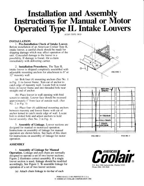
2. <strong>Installation</strong> Procedures. The Type <strong>IL</strong><br />
intake louver is shipped completely assembled with<br />
adjustable mounting anchors for attachment to 8" or<br />
l2" masonry wall.<br />
(a) Bolt four (4) mounting anchors (See No. I<br />
in Fig. 1) to louver frame. Tirrn ear of anchor to<br />
catch edge of masonry wall. Locate bolt in round<br />
holes in louver frame and into threaded hole near<br />
straight end of anchor.<br />
(b) Place louver in wall opening with bird<br />
screen to outside. <strong>Louver</strong> face should be recessed<br />
approximately l" from {ace of outside wall. (See<br />
No. 2 in Fig. l)<br />
(c) Place four (4) additional mounting anchors<br />
between masonry and louver frame with ear of<br />
anchor turned to catch inside edge of wall. Locate<br />
bolt in slotted hole and adiust anchors to hold<br />
louver securely. (See No. i in nig. tl<br />
3. Assembly of Linkage. <strong>Louver</strong> sections are<br />
designed for manual or motorized operation.<br />
Instructions on assembly of linkage for manual<br />
operation are shown below. See back of this sheet<br />
for instructions on assembly of linkage for motor<br />
operation.<br />
ASSEMBLY<br />
1. Assembly of Linkage for Manual<br />
Operation. Linkage and pull chain are normally<br />
designed to operate a set of two louver sections.<br />
Figure 2 illustrates correct assembly. If a single<br />
louver section is used, linkage should be modified<br />
accordingly. See Figure 3. To assemble linkage for<br />
operation of a set of two louver sections:<br />
(a) Attach chain linkage to tie-bar of each<br />
I<br />
I I<br />
FORM 61042-2 (3-88) PRINTED IN U.S.A,<br />
O AMERICAN COOLAIR CORPORATION 1988<br />
FIGURE 2<br />
RE'TUNN;J<br />
! spnrxc f<br />
TIE.BAR<br />
FPULL CHAIN<br />
CIIAIN<br />
AXCHON<br />
I<br />
t I<br />
U t<br />
FIGURE J<br />
I<br />
I I I<br />
I<br />
t t<br />
CffUlain<br />
P.O. Box 2300 Jacksonville, Florida 32203<br />
Phone (904) 389-3646
ASSEMBLY (continued)<br />
louver section as illustrated in Figure 2. Place Shooks<br />
in hole near top of tie bar. Use tie-bars<br />
adjacent to center point. If necessary, move Return<br />
Spring to other tie-bar.<br />
(b) Attach Chain Anchor to frame of left<br />
louver section at lower right hand corner. A<br />
mounting hole is provided at that point.<br />
(c) Adjust louver blades to desired position<br />
and secure pull chain to chain anchor.<br />
2. Assembly of Linkage for Motorized<br />
Operation. Motor and linkage are designed to<br />
operate a set of two louver sections. If a single<br />
louver section is used, motor location remains<br />
unchanged and linkage is modified by adding<br />
an additional spring (provided with the motor<br />
package) as shown in Figure 5. To install motor and<br />
assernble linkage to a set of two louver sections:<br />
(a) Mount motor in lower left corner of rieht<br />
louver section. Use clamping screw and suppoli<br />
clip to secure motor to bottom and side of louver<br />
frame. See Figure 4.<br />
(b) Chain linkage is pre-attached to Operator<br />
Arm on motor. Cut chain linkage to correct length<br />
and attach linkage to tie-bar of each louver section<br />
as illustrated in Figure 4. Place "S" hooks in holes<br />
just below mid-point of tie-bar. Also discard extra<br />
return spring and "S" hooks which are not used.<br />
IMPORIANT: Manually rotate Operator Arm on<br />
motor to "up" position before attaching linkage.<br />
(c) If motor and linkage are used with a single<br />
louver section, return springs should be attached at<br />
top of each tie-bar to insure proper close of blades.<br />
An extra spring for this purpose is provided in the<br />
motor package.<br />
(d) Check voltage and phase on motor<br />
nameplate before connecting the power supply. Do<br />
not operate motor until linkage is connected to<br />
louver.<br />
(e) Wth power connected, operate louver and<br />
adjust linkage if necessary.<br />
CAUTION: Do not return damaged or<br />
defective parts to <strong>American</strong> <strong>Coolair</strong> without prior<br />
authorization. If repairs under warranty are<br />
claimed, see warranty terms in <strong>American</strong> <strong>Coolair</strong><br />
catalog or contact the factory in Jacl