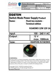
EGSTON
EGSTON
EGSTON

You also want an ePaper? Increase the reach of your titles
YUMPU automatically turns print PDFs into web optimized ePapers that Google loves.
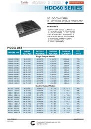
PRODUCT SPECIFICATION N1hxSW3 12W PS EuPII<br />
Document prepared and responsible for<br />
Page<br />
1/20<br />
M. Mauritz Standard Programme<br />
Approved by Day Month Year Revision<br />
M. Obritzhauser 25 10 11 C<br />
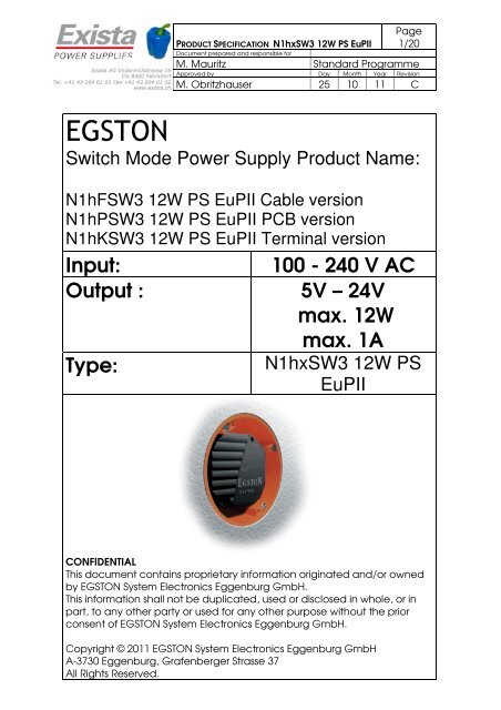
<strong>EGSTON</strong><br />
Switch Mode Power Supply Product Name:<br />
N1hFSW3 12W PS EuPII Cable version<br />
N1hPSW3 12W PS EuPII PCB version<br />
N1hKSW3 12W PS EuPII Terminal version<br />
Input: 100 - 240 V AC<br />
Output : 5V – 24V<br />
max. 12W<br />
Type:<br />
max. 1A<br />
N1hxSW3 12W PS<br />
EuPII<br />
CONFIDENTIAL<br />
This document contains proprietary information originated and/or owned<br />
by <strong>EGSTON</strong> System Electronics Eggenburg GmbH.<br />
This information shall not be duplicated, used or disclosed in whole, or in<br />
part, to any other party or used for any other purpose without the prior<br />
consent of <strong>EGSTON</strong> System Electronics Eggenburg GmbH.<br />
Copyright © 2011 <strong>EGSTON</strong> System Electronics Eggenburg GmbH<br />
A-3730 Eggenburg, Grafenberger Strasse 37<br />
All Rights Reserved.
PRODUCT SPECIFICATION N1hxSW3 12W PS EuPII<br />
Document prepared and responsible for<br />
Page<br />
2/20<br />
M. Mauritz Standard Programme<br />
Approved by Day Month Year Revision<br />
M. Obritzhauser 25 10 11 C<br />
1.1 Evolution............................................................................................................3<br />
2 Scope ............................................................................................................................3<br />
3 Technical Specification Sheet...................................................................................4<br />
3.1 Input Specification ..........................................................................................4<br />
3.2 Safety and Environmental Conditions .........................................................4<br />
3.3 Output Specification.......................................................................................5<br />
3.3.1 Output template...............................................................................6<br />
3.4 Mechanical Parameters.................................................................................7<br />
3.4.1 Screw proposition and max. moment of torque.........................7<br />
3.4.2 Printed circuit board module version:...........................................8<br />
3.4.3 Cable – cable version:.....................................................................9<br />
3.4.4 Terminal version:............................................................................. 11<br />
3.4.5 Housing and Potting...................................................................... 13<br />
4 Marking on the housing........................................................................................... 13<br />
4.1 Laser marking ................................................................................................ 13<br />
5 EMC............................................................................................................................. 14<br />
5.1 Emission with representative 15V device: ................................................ 14<br />
5.2 Immunity To Flicker........................................................................................ 14<br />
5.3 Immunity to Fast Transients (Burst).............................................................. 14<br />
5.4 Immunity to Radiated Electromagnetic Field ......................................... 14<br />
5.5 Immunity to Electrostatic Discharge ......................................................... 14<br />
5.6 Surge Capability ........................................................................................... 14<br />
5.7 Immunity to conducted disturbances...................................................... 14<br />
5.8 Immunity to voltage dips, short interruptions and voltage variations. 15<br />
6 Reliability .................................................................................................................... 16<br />
6.1 MTBF ................................................................................................................ 16<br />
6.2 Maintainability............................................................................................... 16<br />
6.3 Temperature cycle test ............................................................................... 16<br />
7 Safety.......................................................................................................................... 17<br />
7.1 Dielectric Strength........................................................................................ 17<br />
7.2 Over-current Protection .............................................................................. 17<br />
7.3 Single Component Failure........................................................................... 17<br />
7.4 Short Circuit.................................................................................................... 17<br />
8 Approvals and test standards ................................................................................ 18<br />
8.1 General .......................................................................................................... 18<br />
8.2 Test Standards ............................................................................................... 18<br />
8.3 Approvals ....................................................................................................... 18<br />
9 Ordering Information ............................................................................................... 19<br />
10 Packaging and weight............................................................................................ 20
1.1 Evolution<br />
PRODUCT SPECIFICATION N1hxSW3 12W PS EuPII<br />
Document prepared and responsible for<br />
Page<br />
3/20<br />
M. Mauritz Standard Programme<br />
Approved by Day Month Year Revision<br />
M. Obritzhauser 25 10 11 C<br />
Edition Date Responsible Reason of change<br />
A 26.05.2011 Mauritz First edition<br />
B 01.09.2011 Mauritz Adding screw proposition and max.<br />
moment of torque;<br />
Changing Printed circuit board module<br />
version: pin distances;<br />
General housing Dimension: changing<br />
some parameters<br />
C 25.10.2011 Mauritz Mechanical parameter updated<br />
2 SCOPE<br />
This document describes a switch mode power supply unit (AC/DC converter)<br />
with fixed output voltage.<br />
The unit is designed as flush box module with terminals for wire connection or as<br />
a PCB module or as a cable module.<br />
The unit is designed as a built in power supply and has to be installed in a non<br />
operator accessible area.
PRODUCT SPECIFICATION N1hxSW3 12W PS EuPII<br />
Document prepared and responsible for<br />
Page<br />
4/20<br />
M. Mauritz Standard Programme<br />
Approved by Day Month Year Revision<br />
M. Obritzhauser 25 10 11 C<br />
3 TECHNICAL SPECIFICATION SHEET<br />
3.1 Input Specification<br />
Parameter Key Min Typ. Max Unit Test Cond.<br />
Input Voltage UIN 90 264 V AC<br />
Input Current IIN 2 130 400 mA<br />
Input Frequency fIN 47 50 63 Hz<br />
Efficiency<br />
η<br />
80 %<br />
According EuP Tier II<br />
At full load<br />
Switching Frequency fsw 65 kHz<br />
300 mW Without<br />
P stb<br />
load<br />
Stand-by power<br />
According EuP Tier II<br />
Input Voltage<br />
If the input voltage is out of operating range, the power supply does not meet<br />
the full specification. Above the specified upper limit of the input voltage the<br />
unit can get damaged. Below the specified lower limit of the input voltage the<br />
unit does not meet the specification.<br />
Efficiency Under Load<br />
The efficiency is defined as the ratio between the output power and input<br />
power.<br />
3.2 Safety and Environmental Conditions<br />
Parameter Key Min Typ. Max Unit Test Cond.<br />
Dielectric Strength 3 KVAC<br />
Operating<br />
Temperature<br />
-20 50 °C<br />
-4 122 °F<br />
Storage Temperature -30 25 80 °C<br />
-22 77 176 °F<br />
Humidity 95 %<br />
At free<br />
convection
3.3 Output Specification<br />
PRODUCT SPECIFICATION N1hxSW3 12W PS EuPII<br />
Document prepared and responsible for<br />
Page<br />
5/20<br />
M. Mauritz Standard Programme<br />
Approved by Day Month Year Revision<br />
M. Obritzhauser 25 10 11 C<br />
Parameter Key Min Typ. Max Unit Test Cond.<br />
Output Voltage U2 5 24 V 0 – 1A<br />
Output voltage<br />
tolerance<br />
TU2 3 % at PCB<br />
Output Current I2 Nominal 1 A<br />
Max. Overload<br />
current<br />
I2 Overload<br />
160<br />
120<br />
% of I2<br />
Nominal<br />
Output Power P2 12 W<br />
Ripple Voltage<br />
U2,rms<br />
140<br />
140 mVrms<br />
UIN = 264V<br />
UIN = 90V<br />
UIN = 264V<br />
UIN = 90V<br />
The unit is not long time over-current proof. If the unit is powered longer than 1<br />
min in overload conditions (current range between I2 Nominal and I2 Overload ), the<br />
device can be damaged. The period between two overload conditions has to<br />
be at least 15 minutes.
3.3.1 Output template<br />
U2/V 7<br />
6<br />
5<br />
4<br />
3<br />
2<br />
1<br />
0<br />
PRODUCT SPECIFICATION N1hxSW3 12W PS EuPII<br />
Document prepared and responsible for<br />
Page<br />
6/20<br />
M. Mauritz Standard Programme<br />
Approved by Day Month Year Revision<br />
M. Obritzhauser 25 10 11 C<br />
Specified operating area Overload area<br />
Tricle mode<br />
area<br />
0 0.5 I2 1 1.5 I2 Overload<br />
I2/A 2<br />
Specified operating area:<br />
At an output current from 0A to I2 Nominal the unit fulfills all specified data.<br />
Overload area:<br />
At an output current from I2 Nominal to I2 Overload the power supply delivers the<br />
specified output voltage U2.<br />
The unit is not long time overload proof. If the unit is powered longer than 1 min<br />
in overload conditions, the device can be damaged. The period between two<br />
overload conditions has to be at least 15 minutes.<br />
Trickle mode area:<br />
If the power demand would be greater than I2 Overload or the power supply<br />
works in short circuit the output voltage and current can not be defined (this<br />
parameters are not stable). The wattage of the SMPS is de-rated. In this mode<br />
the unit can not be damaged. After removing this conditions the unit fulfills the<br />
specification.
3.4 Mechanical Parameters<br />
PRODUCT SPECIFICATION N1hxSW3 12W PS EuPII<br />
Document prepared and responsible for<br />
Page<br />
7/20<br />
M. Mauritz Standard Programme<br />
Approved by Day Month Year Revision<br />
M. Obritzhauser 25 10 11 C<br />
3.4.1 Screw proposition and max. moment of torque<br />
Max. moment of torque M= 30Ncm<br />
Screw proposition:<br />
Standard: Slotted pan head screw ISO 1580 max. M3<br />
Alternative: Phillips pan head screw ISO 7045 max. M3<br />
Alternative: fillister socket head screw low design ISO 7984 max. M3<br />
Alternative: fillister socket head screw ISO 4762 max. M3
PRODUCT SPECIFICATION N1hxSW3 12W PS EuPII<br />
Document prepared and responsible for<br />
Page<br />
8/20<br />
M. Mauritz Standard Programme<br />
Approved by Day Month Year Revision<br />
M. Obritzhauser 25 10 11 C<br />
3.4.2 Printed circuit board module version:
3.4.3 Cable – cable version:<br />
PRODUCT SPECIFICATION N1hxSW3 12W PS EuPII<br />
Document prepared and responsible for<br />
Page<br />
9/20<br />
M. Mauritz Standard Programme<br />
Approved by Day Month Year Revision<br />
M. Obritzhauser 25 10 11 C
PRODUCT SPECIFICATION N1hxSW3 12W PS EuPII<br />
Document prepared and responsible for<br />
Page<br />
10/20<br />
M. Mauritz Standard Programme<br />
Approved by Day Month Year Revision<br />
M. Obritzhauser 25 10 11 C
3.4.4 Terminal version:<br />
PRODUCT SPECIFICATION N1hxSW3 12W PS EuPII<br />
Document prepared and responsible for<br />
Page<br />
11/20<br />
M. Mauritz Standard Programme<br />
Approved by Day Month Year Revision<br />
M. Obritzhauser 25 10 11 C
3.4.4.1 Connector at terminal version<br />
PRODUCT SPECIFICATION N1hxSW3 12W PS EuPII<br />
Document prepared and responsible for<br />
Page<br />
12/20<br />
M. Mauritz Standard Programme<br />
Approved by Day Month Year Revision<br />
M. Obritzhauser 25 10 11 C<br />
prim.: Weidmüller contacts LMZF 5/2/135 3.5OR<br />
Connectable conductor:<br />
Clamp range, min. 0,13 mm²<br />
Clamp range, max. 2,5 mm²<br />
AWG, min. 26<br />
AWG, max. 14<br />
Solid, min. H05(07) V-U 0,13 mm²<br />
Solid, max. H05(07) V-U 2,5 mm²<br />
Stranded, min H05(07) V-K 0,13 mm²<br />
Stranded, max H05(07) V-K 2,5 mm²<br />
With ferrule according Din 46 228/1, min. 0,25 mm²<br />
With ferrule according Din 46 228/1, max. 1,5 mm²<br />
With ferrule with collar according Din 46 228/4, min. 0,25 mm²<br />
With ferrule with collar according Din 46 228/4, max. 1,5 mm²<br />
sec.: Phoenix contacts SPTA 1/2-3,5<br />
Connectable conductor:<br />
Conductor cross section solid, min. 0,2 mm²<br />
Conductor cross section solid, max. 1,5 mm²<br />
Conductor cross section stranded, min. 0,2 mm²<br />
Conductor cross section stranded, max. 1 mm²<br />
Conductor cross section stranded with ferrule without<br />
plastic sleeve, min. 0,25 mm²<br />
Conductor cross section stranded with ferrule without<br />
plastic sleeve, max. 0,75 mm²<br />
Conductor cross section stranded with ferrule with<br />
plastic sleeve, min. 0,25 mm²<br />
Conductor cross section stranded with ferrule with<br />
plastic sleeve, max. 0,75 mm²<br />
AWG, min. 24<br />
AWG, max. 16
3.4.5 Housing and Potting<br />
The device is potted.<br />
Housing Material PA<br />
Flammability rate of<br />
Housing<br />
V0<br />
Potting Material Polyurethane, UL listed<br />
Colour of Housing black<br />
4 MARKING ON THE HOUSING<br />
4.1 Laser marking<br />
PRODUCT SPECIFICATION N1hxSW3 12W PS EuPII<br />
Document prepared and responsible for<br />
Page<br />
13/20<br />
M. Mauritz Standard Programme<br />
Approved by Day Month Year Revision<br />
M. Obritzhauser 25 10 11 C<br />
Product name<br />
Input parameters<br />
Output parameters<br />
Safety instructions<br />
Date code of production<br />
CE marking<br />
Approval marks
5 EMC<br />
PRODUCT SPECIFICATION N1hxSW3 12W PS EuPII<br />
Document prepared and responsible for<br />
Page<br />
14/20<br />
M. Mauritz Standard Programme<br />
Approved by Day Month Year Revision<br />
M. Obritzhauser 25 10 11 C<br />
The units meet the following EMC requirements:<br />
5.1 Emission with representative 15V device:<br />
Test passed according to EN55022 Class B and FCC15 Class B.<br />
5.2 Immunity To Flicker<br />
Test according to EN 61000-3-2<br />
5.3 Immunity to Fast Transients (Burst)<br />
Test according to EN61000-4-4<br />
Input Line: 2.0kV – 5/50 ns – 5.0 kHz<br />
Output Line: 2.0kV – 5/50 ns – 5.0 kHz<br />
5.4 Immunity to Radiated Electromagnetic Field<br />
Test according to EN 61000-4-3<br />
Test characteristic: 80 – 1000 MHz; 80% AM (1kHz), 3V/m<br />
5.5 Immunity to Electrostatic Discharge<br />
Test according to EN 61000-4-2<br />
Test characteristic: Contact discharge 6kV<br />
Air discharge 8kV<br />
5.6 Surge Capability<br />
Test according to EN61000-4-5<br />
Test characteristic: line to line: 1kV Surge<br />
line to earth: 2kV Surge<br />
5.7 Immunity to conducted disturbances<br />
Test according to EN 61000-4-6<br />
Test characteristic: 150kHz – 80 MHz; 80% AM (1kHz), 3V
PRODUCT SPECIFICATION N1hxSW3 12W PS EuPII<br />
Document prepared and responsible for<br />
Page<br />
15/20<br />
M. Mauritz Standard Programme<br />
Approved by Day Month Year Revision<br />
M. Obritzhauser 25 10 11 C<br />
5.8 Immunity to voltage dips, short interruptions and voltage<br />
variations<br />
Test according to EN 61000-4-11<br />
Test criterion C
6 RELIABILITY<br />
6.1 MTBF<br />
In evaluation.<br />
6.2 Maintainability<br />
The power supply is not to be repaired.<br />
6.3 Temperature cycle test<br />
PRODUCT SPECIFICATION N1hxSW3 12W PS EuPII<br />
Document prepared and responsible for<br />
Page<br />
16/20<br />
M. Mauritz Standard Programme<br />
Approved by Day Month Year Revision<br />
M. Obritzhauser 25 10 11 C<br />
During quality approval the unit passed the <strong>EGSTON</strong> standard temperature<br />
cycle test.
7 SAFETY<br />
The units pass the following tests:<br />
7.1 Dielectric Strength<br />
PRODUCT SPECIFICATION N1hxSW3 12W PS EuPII<br />
Document prepared and responsible for<br />
Page<br />
17/20<br />
M. Mauritz Standard Programme<br />
Approved by Day Month Year Revision<br />
M. Obritzhauser 25 10 11 C<br />
The input isolation test voltage is 3kV 50/60 Hz, sinusoidal waveform. Test<br />
duration is 2 seconds for 100% test, 1minute 4,24KV DC or lot-test.<br />
7.2 Over-current Protection<br />
The unit is not long time over-current proof. If the unit is powered longer than 1<br />
min in overload conditions, the device can be damaged. The period between<br />
two overload conditions has to be at least 15 minutes.<br />
7.3 Single Component Failure<br />
A single component failure does not cause any damage to persons or ambient<br />
(fire, explosions, etc).<br />
7.4 Short Circuit<br />
The power supply is designed with a short circuit protection. A shortened<br />
output does not cause any damage to persons or ambient (fire, explosions,<br />
etc.) After removing this conditions the unit fulfills the specification.
PRODUCT SPECIFICATION N1hxSW3 12W PS EuPII<br />
Document prepared and responsible for<br />
Page<br />
18/20<br />
M. Mauritz Standard Programme<br />
Approved by Day Month Year Revision<br />
M. Obritzhauser 25 10 11 C<br />
8 APPROVALS AND TEST STANDARDS<br />
8.1 General<br />
The transformer is designed as a safety transformer according EN 61558-2-16.<br />
The device is galvanically isolated.<br />
The isolation class is B.<br />
The device (without contacts) is equivalent to IP65. External tests can be done<br />
on request.<br />
8.2 Test Standards<br />
EN 60950-1<br />
EN 60335-1<br />
EN 61558-2-16<br />
UL 60950-1<br />
EN 55014-1<br />
EN 55014-2<br />
EN 55022<br />
EN 55024<br />
8.3 Approvals<br />
C/US NRTL approval issued by Curtis Straus<br />
ENEC<br />
Conformity with the EU low voltage directive and EMC directive
9 ORDERING INFORMATION<br />
PRODUCT SPECIFICATION N1hxSW3 12W PS EuPII<br />
Document prepared and responsible for<br />
Page<br />
19/20<br />
M. Mauritz Standard Programme<br />
Approved by Day Month Year Revision<br />
M. Obritzhauser 25 10 11 C<br />
POWER CLASS 12 Watt<br />
N SUPPLY TYPE <strong>EGSTON</strong> Power Supply Type<br />
1 OPERATION TEMP. RANGE 1 = -20°C to +50°C<br />
h PRIMARY CONNECTOR h = flush box module<br />
F CABLE CONNECTION F = Fixed Cable<br />
P P = PCB Module<br />
K K = Terminal edition<br />
S APPLICATION S = Standard<br />
M = Medical<br />
H = Household<br />
W WIDE INPUT RANGE W = 90V-264V<br />
3 OUTPUT STABILITY 3 = 3%<br />
12W HOUSING DIMENSION 12W<br />
12V OUTPUT VOLTAGE 5V-24V<br />
1A OUTPUT CURRENT 1000mA max.
10 PACKAGING AND WEIGHT<br />
N1hFSW3 PCB module<br />
PRODUCT SPECIFICATION N1hxSW3 12W PS EuPII<br />
Document prepared and responsible for<br />
Page<br />
20/20<br />
M. Mauritz Standard Programme<br />
Approved by Day Month Year Revision<br />
M. Obritzhauser 25 10 11 C<br />
pcs kg size<br />
Single Carton 1 0,11 95x85x30<br />
Power Supply per Packaging Case 50 5,5 427x196x165<br />
Power Supply per Layer (EU- Pallet)<br />
10 Packaging cases<br />
500 76 1200x800x165<br />
1 Full Pallet (9 Layer) 4500 516 1200x800x1500<br />
N1hFSW3 cable version<br />
pcs kg size<br />
Single Carton 1 0,12 95x85x30<br />
Power Supply per Packaging Case 50 6 427x196x165<br />
Power Supply per Layer (EU- Pallet)<br />
10 Packaging cases<br />
500 81 1200x800x165<br />
1 Full Pallet (9 Layer) 4500 561 1200x800x1500<br />
N1hFSW3 terminal version<br />
pcs kg size<br />
Single Carton 1 0,12 95x85x30<br />
Power Supply per Packaging Case 50 6 427x196x165<br />
Power Supply per Layer (EU- Pallet)<br />
7 Packaging cases<br />
350 63 1200x800x165<br />
1 Full Pallet (7 Layer) 2450 315 1200x800x1500