
You also want an ePaper? Increase the reach of your titles
YUMPU automatically turns print PDFs into web optimized ePapers that Google loves.
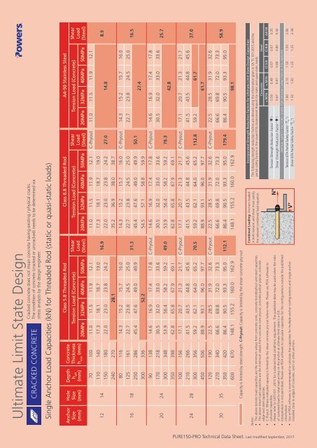
Ultimate Limit State Design<br />
CRACKED CONCRETE<br />
Cracked concrete does not mean concrete having existing / physical cracks.<br />
The condition of concrete (cracked or uncracked) needs to be determined via<br />
stress analysis by the design engineer.<br />
Single Anchor Load Capacities (kN) for Threaded Rod (static or quasi-static loads)<br />
Anchor<br />
Size<br />
(mm)<br />
Hole<br />
Size<br />
(mm)<br />
12 14<br />
16 18<br />
20 24<br />
24 28<br />
30 35<br />
Depth<br />
h eff<br />
(mm)<br />
Concrete<br />
Thickness<br />
h min<br />
(mm)<br />
Class 5.8 Threaded Rod Class 8.8 Threaded Rod A4-50 Stainless Steel<br />
Tension Load (Concrete) Shear<br />
Load<br />
(Steel)<br />
Tension Load (Concrete) Shear<br />
Load<br />
(Steel)<br />
Tension Load (Concrete) Shear<br />
Load<br />
(Steel)<br />
20MPa 32MPa 40MPa 50MPa 20MPa 32MPa 40MPa 50MPa 20MPa 32MPa 40MPa 50MPa<br />
70 100 11.0 11.5 11.9 12.1<br />
110 140 17.3 18.1 18.7 19.0 17.3 18.1 18.7 19.0<br />
16.9<br />
<strong>150</strong> 180 22.0 23.0 23.8 24.2 22.0 23.0 23.8 24.2<br />
240 270 28.1 35.2 36.9 38.0 38.7<br />
80 116 14.3 15.2 15.7 16.0<br />
125 161 22.7 23.8 24.5 25.0 22.7 23.8 24.5 25.0<br />
31.3<br />
250 286 45.4 47.6 49.0 49.9 45.4 47.6 49.0 49.9<br />
300 336 52.2 54.5 57.1 58.8 59.9<br />
11.0 11.5 11.9 12.1 C-Pryout 11.0 11.5 11.9 12.1<br />
27.0 14.8<br />
14.3 15.2 15.7 16.0 C-Pryout 14.3 15.2 15.7 16.0<br />
50.1<br />
22.7 23.8 24.5 25.0<br />
90 138 14.6 16.9 17.4 17.8 C-Pryout 14.6 16.9 17.4 17.8 C-Pryout 14.6 16.9 17.4 17.8<br />
170 218 30.5 32.0 33.0 33.6<br />
30.5 32.0 33.0 33.6<br />
300 348 53.9 56.4 58.2 59.2 49.0 53.9 56.4 58.2 59.2<br />
350 398 62.8 65.8 67.9 69.1 62.8 65.8 67.9 69.1<br />
78.3<br />
27.4<br />
30.5 32.0 33.0 33.6<br />
100 156 17.1 20.7 21.3 21.7 C-Pryout 17.1 20.7 21.3 21.7 C-Pryout 17.1 20.7 21.3 21.7<br />
210 266 41.5 43.5 44.8 45.6<br />
41.5 43.5 44.8 45.6<br />
300 356 59.2 62.1 64.0 65.2 70.5 59.2 62.1 64.0 65.2 112.8 59.2 61.7<br />
42.8<br />
41.5 43.5 44.8 45.6<br />
450 506 88.9 93.1 96.0 97.7 88.9 93.1 96.0 97.7 61.7<br />
120 190 22.5 28.5 31.9 32.6 C-Pryout 22.5 28.5 31.9 32.6 C-Pryout 22.5 28.5 31.9 32.6<br />
270 340 66.6 69.8 72.0 73.3<br />
66.6 69.8 72.0 73.3<br />
66.6 69.8 72.0 73.3<br />
350 420 86.4 90.5 93.3 95.0 112.1 86.4 90.5 93.3 95.0 179.4 86.4 90.5 93.3 95.0<br />
600 670 148.1 155.2 160.0 162.9 148.1 155.2 160.0 162.9 98.1<br />
8.9<br />
16.5<br />
25.7<br />
37.0<br />
58.9<br />
Capacity is limited by steel strength. C-Pryout: Capacity is limited by the shear concrete pry-out<br />
Notes:<br />
• The above tension load capacities are the minimum values from concrete cone, concrete bond/pullout and steel capacities.<br />
• The above shear load capacities are the minimum values from concrete cone pryout, concrete pullout pryout, concrete<br />
edge and steel capacities.<br />
• C-Pryout: Where indicated capacity is limited by the shear concrete pry-out failure mode. Please use PDA software to<br />
calculate capacities.<br />
• Please refer to SATS101 : 2015 for sustained load conditions requirement. The published data may be used when the ratio<br />
of sustained load to total load acting on the anchor at ultimate limit state is ≤ 0.6.<br />
• Interpolation is not permitted. Please use PDA software to calculate capacities for the configurations outside the published<br />
information.<br />
• Use of PDA software is recommended to calculate the capacities for multiple anchor configurations and single anchor<br />
installed close to edge/s of concrete, and / or other anchors.<br />
Combined Loading: Anchors loaded<br />
in both tension and shear must satisfy<br />
the relevant combined load equation.<br />
Incorporated Strength Reduction Factors for Ultimate Limit State Design Capacities:<br />
The following strength reduction factors are derived using the information given in SA TS 101:2015 and the<br />
partial safety factors in the issued ETA (Assessment Report) for static and quasi-static loads.<br />
Concrete Steel<br />
≤ M16 > M16 Cl 5.8 Cl 8.8 A4-50<br />
Tension (Strength Reduction Factor “ ”) 0.56 0.48 0.67 0.67 0.35<br />
Shear (Strength Reduction Factor “ ”) 0.67 0.67 0.80 0.80 0.42<br />
PARTIAL SAFETY FACTORS GIVEN FOR DESIGN CAPACITIES IN ETA-08/0376<br />
M<br />
Tension (ETA Partial Safety Factor “ ”) 1.80 2.10 1.50 1.50 2.86<br />
Shear (ETA Partial Safety Factor “ M<br />
”) 1.50 1.50 1.25 1.25 2.38<br />
PURE<strong>150</strong>-PRO <strong>Technical</strong> <strong>Data</strong> <strong>Sheet</strong>. Last modified September, 2017