
Create successful ePaper yourself
Turn your PDF publications into a flip-book with our unique Google optimized e-Paper software.
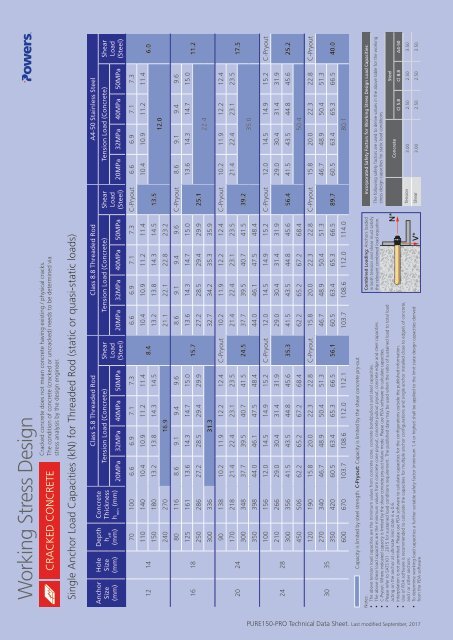
Working Stress Design<br />
CRACKED CONCRETE<br />
Cracked concrete does not mean concrete having existing / physical cracks.<br />
The condition of concrete (cracked or uncracked) needs to be determined via<br />
stress analysis by the design engineer.<br />
Single Anchor Load Capacities (kN) for Threaded Rod (static or quasi-static loads)<br />
Anchor<br />
Size<br />
(mm)<br />
Hole<br />
Size<br />
(mm)<br />
12 14<br />
16 18<br />
20 24<br />
24 28<br />
30 35<br />
Depth<br />
h eff<br />
(mm)<br />
Concrete<br />
Thickness<br />
h min<br />
(mm)<br />
Class 5.8 Threaded Rod Class 8.8 Threaded Rod A4-50 Stainless Steel<br />
Tension Load (Concrete) Shear<br />
Load<br />
(Steel)<br />
Tension Load (Concrete) Shear<br />
Load<br />
(Steel)<br />
Tension Load (Concrete) Shear<br />
Load<br />
(Steel)<br />
20MPa 32MPa 40MPa 50MPa 20MPa 32MPa 40MPa 50MPa 20MPa 32MPa 40MPa 50MPa<br />
70 100 6.6 6.9 7.1 7.3<br />
6.6 6.9 7.1 7.3 C-Pryout 6.6 6.9 7.1 7.3<br />
110 140 10.4 10.9 11.2 11.4 10.4 10.9 11.2 11.4<br />
10.4 10.9 11.2 11.4<br />
8.4<br />
6.0<br />
<strong>150</strong> 180 13.2 13.8 14.3 14.5 13.2 13.8 14.3 14.5 13.5<br />
12.0<br />
240 270 16.9 21.1 22.1 22.8 23.2<br />
80 116 8.6 9.1 9.4 9.6<br />
8.6 9.1 9.4 9.6 C-Pryout 8.6 9.1 9.4 9.6<br />
125 161 13.6 14.3 14.7 15.0 13.6 14.3 14.7 15.0<br />
13.6 14.3 14.7 15.0<br />
15.7<br />
11.2<br />
250 286 27.2 28.5 29.4 29.9 27.2 28.5 29.4 29.9 25.1<br />
22.4<br />
300 336 31.3 32.7 34.2 35.3 35.9<br />
90 138 10.2 11.9 12.2 12.4 C-Pryout 10.2 11.9 12.2 12.4 C-Pryout 10.2 11.9 12.2 12.4<br />
170 218 21.4 22.4 23.1 23.5<br />
21.4 22.4 23.1 23.5<br />
21.4 22.4 23.1 23.5<br />
17.5<br />
300 348 37.7 39.5 40.7 41.5 24.5 37.7 39.5 40.7 41.5 39.2<br />
35.0<br />
350 398 44.0 46.1 47.5 48.4 44.0 46.1 47.5 48.4<br />
100 156 12.0 14.5 14.9 15.2 C-Pryout 12.0 14.5 14.9 15.2 C-Pryout 12.0 14.5 14.9 15.2 C-Pryout<br />
210 266 29.0 30.4 31.4 31.9<br />
29.0 30.4 31.4 31.9<br />
29.0 30.4 31.4 31.9<br />
300 356 41.5 43.5 44.8 45.6 35.3 41.5 43.5 44.8 45.6 56.4 41.5 43.5 44.8 45.6 25.2<br />
450 506 62.2 65.2 67.2 68.4 62.2 65.2 67.2 68.4 50.4<br />
120 190 15.8 20.0 22.3 22.8 C-Pryout 15.8 20.0 22.3 22.8 C-Pryout 15.8 20.0 22.3 22.8 C-Pryout<br />
270 340 46.7 48.9 50.4 51.3<br />
46.7 48.9 50.4 51.3<br />
46.7 48.9 50.4 51.3<br />
350 420 60.5 63.4 65.3 66.5 56.1 60.5 63.4 65.3 66.5 89.7 60.5 63.4 65.3 66.5 40.0<br />
600 670 103.7 108.6 112.0 112.1 103.7 108.6 112.0 114.0 80.1<br />
Capacity is limited by steel strength. C-Pryout: Capacity is limited by the shear concrete pry-out<br />
Notes:<br />
• The above tension load capacities are the minimum values from concrete cone, concrete bond/pullout and steel capacities.<br />
• The above shear load capacities are the minimum values from concrete cone pryout, concrete pullout pryout, concrete edge and steel capacities.<br />
• C-Pryout: Where indicated capacity is limited by the shear concrete pry-out failure mode. Please use PDA software to calculate capacities.<br />
• Please refer to SATS101 : 2015 for sustained load conditions requirement. The published data may be used when the ratio of sustained load to total load<br />
acting on the anchor at ultimate limit state is ≤ 0.6.<br />
• Interpolation is not permitted. Please use PDA software to calculate capacities for the configurations outside the published information.<br />
• Use of PDA software is recommended to calculate the capacities for multiple anchor configurations and single anchor installed close to edge/s of concrete,<br />
and / or other anchors.<br />
• To determine working load capacities a further suitable safety factor (minimum 1.4 or higher) shall be applied to the limit state design capacities derived<br />
from the PDA software.<br />
Combined Loading: Anchors loaded<br />
in both tension and shear must satisfy<br />
the relevant combined load equation.<br />
Incorporated Safety Factors for Working Stress Design Load Capacities:<br />
The following safety factors are used to derive values in the above table for the working<br />
stress design capacities for static load conditions<br />
Steel<br />
Concrete<br />
Cl 5.8 Cl 8.8 A4-50<br />
Tension 3.00 2.50 2.50 3.50<br />
Shear 3.00 2.50 2.50 3.50<br />
PURE<strong>150</strong>-PRO <strong>Technical</strong> <strong>Data</strong> <strong>Sheet</strong>. Last modified September, 2017