SC Pro Technical Data Sheet
You also want an ePaper? Increase the reach of your titles
YUMPU automatically turns print PDFs into web optimized ePapers that Google loves.
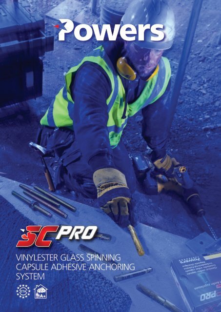
VINYLESTER GLASS SPINNING<br />
CAPSULE ADHESIVE ANCHORING<br />
SYSTEM
The Powers Plus range includes many mechanical and chemical anchoring systems the have<br />
ETA reports and can be used with confidence to meet the new NCC requirements.<br />
Approval Listing<br />
Anchor products holding a European <strong>Technical</strong> Approval/Assessment (ETA) are qualified according to one of the<br />
following technical guidelines (ETAG):<br />
• ETAG 001 for metal anchors installed in concrete.<br />
(Option 1 for cracked concrete, Option 7 for uncracked concrete, Part 6 for multiple use for non-structural applications)<br />
• ETAG 029 for metal injection anchors installed in masonry.<br />
• EOTA TR 023 for post-installed reinforcement bars.<br />
<strong>Pro</strong>ducts complying with European standards or approvals are marked with the CE Marking.<br />
VOC CLASSIFICATION<br />
<strong>Pro</strong>ducts tested for the emission of volatile substances in indoor air, with a risk of inhalation toxicity, on a scale<br />
ranging from class A + (very low emissions) to C (high emissions) level.<br />
POWERS is one of the founding members of AEFAC (Australian Engineered Fasteners and Anchor Council).<br />
AEFAC is a consortium made of leading industry partners / suppliers of quality anchors to the construction industry<br />
and Swinburne University of Technology.<br />
AEFAC is a new industry-focused initiative which aims to set the standard for the specification, selection, design,<br />
applications and installation of structural anchors and fasteners in the Australian construction industry. AEFAC aims<br />
to enhance safety and efficiency associated with the use of structural anchors and fasteners. AEFAC is based at<br />
Swinburne University of Technology with access to state-of-the-art testing and research capabilities.<br />
The guidelines and resources being developed by AEFAC are intended to become the codes of practice in Australia.<br />
As well as being a founding member, POWERS is also on the Board and <strong>Technical</strong> Committee of AEFAC. POWERS<br />
also retains membership in several international organisations including Concrete Anchoring Manufacturers.<br />
Quality Control <strong>Pro</strong>cedures<br />
<strong>SC</strong>-PRO Vinylester glass spinning capsule adhesive anchor system is packaged in cartons. Each carton contains an<br />
expiry date which provides traceability of the components back to the original manufacturing batch. Every batch of<br />
material is subjected to extensive physical and chemical property testing during manufacture. Each capsule batch<br />
is tested as an installed anchor to ensure that the proper bond strength is developed. These procedures ensure<br />
consistent, top-quality performance to the specifier and the installer of the <strong>SC</strong>-PRO vinylester adhesive anchor.<br />
OH&S<br />
Safety <strong>Data</strong> <strong>Sheet</strong>s are available on request (Ref. Chemwatch 63999) or can be downloaded from<br />
www.powers.com.au<br />
2 <strong>SC</strong>-PRO <strong>Technical</strong> <strong>Data</strong> <strong>Sheet</strong>. Last modified September, 2017
<strong>SC</strong>-PRO<br />
Vinylester Glass Spinning Capsule Adhesive Anchor System<br />
The <strong>SC</strong>-PRO anchor system consists of integrated two-component glass<br />
capsules and matching chisel pointed anchor rods which are installed using a<br />
rotary hammer. An outer capsule contains epoxy acrylate resin (vinyl-ester) in<br />
which quartz aggregate is suspended. The inner capsule contains a hardening<br />
agent. <strong>SC</strong>-PRO capsules are the best solution for simple, no fuss, fast setting at<br />
standard embedment depths with controlled wastage.<br />
During installation, the <strong>SC</strong>-PRO system bonds the threaded rod to the base material so no<br />
expansion forces are exerted against the walls of the hole in the base material. Unlike expansion<br />
anchors, the anchor can be set close to the edge of concrete.<br />
Features<br />
• Simple, fast installation<br />
• Pre-measured adhesive volumes avoids waste - amount of mortar is exactly fitted to the<br />
drill hole diameter<br />
• Designed for use with chisel pointed threaded rod<br />
• Usable in a wide range of weather conditions<br />
• Long shelf life of 18 months*<br />
• Low odour level (Low VOC)<br />
• Curing time: 20 minutes at 20°C<br />
• No expansion forces - small spacing and small edge distance possible<br />
• Two approved temperature ranges: 24/40°C and 50/80°C<br />
*from date of manufacture<br />
Approvals<br />
The following ETA assessment reports can be used to design anchors in accordance with SA TS<br />
101:2015 which is referenced in the National Construction Code (NCC) 2016:<br />
• ETA-11/0473 ETAG 001-5 Option 7 - Threaded rod (Uncracked concrete)<br />
• Approved for two temperature ranges 24°C/40°C & 50°C/80°C<br />
VOC CLASSIFICATION<br />
APPROVED BASE MATERIAL LOADING CONDITIONS HOLE CONDITIONS<br />
Uncracked<br />
Concrete<br />
Cracked Concrete Solid Brick Hollow Brick Static Load Quasi-Static Load Seismic Moderate Wind High Wind<br />
Dry Hole/ Wet<br />
Concrete<br />
Flooded Holes Core Drillled<br />
Size Capsule Dia Drill Dia Embed Depth Box Qty Carton Qty Part No.<br />
M8 9 10 80 10 500 <strong>SC</strong>-PROM8-PWR<br />
M10 11 12 90 10 500 <strong>SC</strong>-PROM10-PWR<br />
M12 13 14 110 10 500 <strong>SC</strong>-PROM12-PWR<br />
M16 17 18 125 10 200 <strong>SC</strong>-PROM16-PWR<br />
M20 17 22 170 10 100 <strong>SC</strong>-PROM20-PWR<br />
M24 22 26 210 6 60 <strong>SC</strong>-PROM24-PWR<br />
Please refer to the relevant ETA / ICC-ES report for complete information before selection, design and use to check suitability of the product.<br />
<strong>SC</strong>-PRO <strong>Technical</strong> <strong>Data</strong> <strong>Sheet</strong>. Last Modified September, 2017<br />
3
Ultimate Limit State Design<br />
UNCRACKED CONCRETE<br />
Concrete Temperature Range: 40ºC/24ºC (Maximum long term 24ºC and Maximum short term 40ºC).<br />
Concrete Thickness = 1xh min<br />
where h min<br />
as per ETA.<br />
Hole condition: Dry/wet, non-flooded hole.<br />
Drilling method: HAMMER DRILLED HOLES ONLY<br />
Edge Distance: No concrete edge distance considered. (i.e. edge distance > maximum (10 X h eff<br />
& 60 X d) in all directions).<br />
Spacing between anchors: The values are for single anchors installed well away from concrete edges and other anchors. No spacing effects considered.<br />
Single Anchor Load Capacities (kN) for Threaded Rod (static or quasi-static loads)<br />
Class 5.8 Threaded Rod Class 8.8 Threaded Rod A4-50 Stainless Steel<br />
Anchor<br />
Size<br />
(mm)<br />
Hole<br />
Size<br />
(mm)<br />
Depth<br />
h eff<br />
(mm)<br />
Concrete<br />
Thickness<br />
(mm)<br />
Tension Load (Concrete)<br />
Shear<br />
Load<br />
(Steel)<br />
Tension Load (Concrete)<br />
Shear<br />
Load<br />
(Steel)<br />
Tension Load (Concrete)<br />
20MPa 32MPa 40MPa 50MPa 20MPa 32MPa 40MPa 50MPa 20MPa 32MPa 40MPa 50MPa<br />
Shear<br />
Load<br />
(Steel)<br />
8 10 80 110 12.2 7.3 16.1 18.9 19.5 11.7 6.4 3.8<br />
10 12 90 120 19.3 11.6 22.6 26.5 28.5 30.3 18.6 10.2 6.1<br />
12 14 110 140 28.1 16.9 33.2 38.9 41.8 44.5 27.0 14.8 8.9<br />
16 18 125 160 47.1 52.2 31.3 47.1 58.9 63.3 67.4 50.1 27.4 16.5<br />
20 22 170 220 74.6 81.6 49.0 74.6 91.8 98.7 105.0 78.3 42.8 25.7<br />
24 26 210 260 102.5 117.5 70.5 102.5 129.6 144.9 155.6 112.8 61.7 37.0<br />
Capacity is limited by steel strength.<br />
Notes:<br />
• The above tension load capacities are the minimum values from concrete cone, concrete bond/pullout and steel capacities.<br />
• The above shear load capacities are the minimum values from concrete cone pryout, concrete pullout pryout, concrete<br />
edge and steel capacities.<br />
• Please refer to SA TS 101 : 2015 for sustained load conditions requirement. The published data may be used when the<br />
ratio of sustained load to total load acting on the anchor at ultimate limit state is ≤ 0.6.<br />
• Interpolation is not permitted. Please use PDA software to calculate capacities for the configurations outside the published<br />
information.<br />
• Use of PDA software is recommended to calculate the capacities for multiple anchor configurations and single anchor<br />
installed close to edge/s of concrete and / or other anchors.<br />
Combined Loading: Anchors loaded<br />
in both tension and shear must satisfy<br />
the relevant combined load equation.<br />
Incorporated Strength Reduction Factors for Ultimate Limit State Design Capacities:<br />
The following strength reduction factors are derived using the information given in SA TS 101:2015 and the<br />
partial safety factors in the issued ETA (Assessment Report) for static and quasi-static loads.<br />
Concrete Steel<br />
< M30 M30 Cl 5.8 Cl 8.8 A4-50<br />
Tension (Strength Reduction Factor “ ”) 0.67 0.56 0.67 0.67 0.35<br />
Shear (Strength Reduction Factor “ ”) 0.67 0.67 0.80 0.80 0.42<br />
PARTIAL SAFETY FACTORS GIVEN FOR DESIGN CAPACITIES IN ETA-11/0473<br />
M<br />
Tension (ETA Partial Safety Factor “ ”) 1.50 1.80 1.50 1.50 2.86<br />
Shear (ETA Partial Safety Factor “ M<br />
”) 1.50 1.50 1.25 1.25 2.38<br />
<strong>SC</strong>-PRO <strong>Technical</strong> <strong>Data</strong> <strong>Sheet</strong>. Last modified September, 2017
Working Stress Design<br />
UNCRACKED CONCRETE<br />
Concrete Temperature Range: 40 0 C/24 0 C (Maximum long term 24 0 C and Maximum short term 40 0 C).<br />
Concrete Thickness = 1xh min<br />
where h min<br />
as per ETA.<br />
Hole condition: Dry/wet, non-flooded hole.<br />
Drilling method: HAMMER DRILLED HOLES ONLY<br />
Edge Distance: No concrete edge distance effect considered.(i.e. edge distance > maximum (10 X h eff<br />
& 60 X d) in all directions).<br />
Spacing between anchors: The values are for single anchors installed well away from concrete edges and other anchors. No spacing effects considered.<br />
Single Anchor Load Capacities (kN) for Threaded Rod (static or quasi-static loads)<br />
Class 5.8 Threaded Rod Class 8.8 Threaded Rod A4-50 Stainless Steel<br />
Anchor<br />
Size<br />
(mm)<br />
Hole<br />
Size<br />
(mm)<br />
Depth<br />
h eff<br />
(mm)<br />
Concrete<br />
Thickness<br />
(mm)<br />
Tension Load (Concrete)<br />
Shear<br />
Load<br />
(Steel)<br />
Tension Load (Concrete)<br />
Shear<br />
Load<br />
(Steel)<br />
Tension Load (Concrete)<br />
20MPa 32MPa 40MPa 50MPa 20MPa 32MPa 40MPa 50MPa 20MPa 32MPa 40MPa 50MPa<br />
Shear<br />
Load<br />
(Steel)<br />
8 10 80 110 7.3 3.7 8.0 9.4 10.1 10.8 5.9 5.2 2.6<br />
10 12 90 120 11.3 11.6 5.8 11.3 13.3 14.3 15.2 9.3 8.3 4.1<br />
12 14 110 140 16.6 16.9 8.4 16.6 19.4 20.9 22.2 13.5 12.0 6.0<br />
16 18 125 160 23.5 29.5 31.3 15.7 23.5 29.5 31.7 33.7 25.1 22.4 11.2<br />
20 22 170 220 37.3 45.9 49.0 24.5 37.3 45.9 49.3 52.5 39.2 35.0 17.5<br />
24 26 210 260 51.2 64.8 70.5 35.3 51.2 64.8 72.4 77.8 56.4 50.4 25.2<br />
Capacity is limited by steel strength.<br />
Notes:<br />
• The above tension load capacities are the minimum values from concrete cone, concrete bond/pullout and steel capacities.<br />
• The above shear load capacities are the minimum values from concrete cone pryout, concrete pullout pryout, concrete edge and steel capacities.<br />
• Please refer to SA TS 101 : 2015 for sustained load conditions requirement. The published data may be used when the ratio of sustained load to total load<br />
acting on the anchor at ultimate limit state is ≤ 0.6.<br />
• Interpolation is not permitted. Please use PDA software to calculate capacities for the configurations outside the published information.<br />
• Use of PDA software is recommended to calculate the capacities for multiple anchor configurations and single anchor installed close to edge/s of concrete<br />
and / or other anchors.<br />
• To determine working load capacities a further suitable safety factor (minimum 1.4 or higher) shall be applied to the limit state design capacities derived<br />
from the PDA software.<br />
Combined Loading: Anchors loaded<br />
in both tension and shear must satisfy<br />
the relevant combined load equation.<br />
Incorporated Safety Factors for Working Stress Design Load Capacities:<br />
The following safety factors are used to derive values in the above table for the working<br />
stress design capacities for static load conditions<br />
Steel<br />
Concrete<br />
Cl 5.8 Cl 8.8 A4-50<br />
Tension 3.00 2.50 2.50 3.50<br />
Shear 3.00 2.50 2.50 3.50<br />
<strong>SC</strong>-PRO <strong>Technical</strong> <strong>Data</strong> <strong>Sheet</strong>. Last modified September, 2017
Material <strong>Pro</strong>perties<br />
<strong>SC</strong>-PRO is a two-component styrene-free vinylester glass spinning capsule adhesive anchoring system. It has better resistance to<br />
moisture and better chemical resistance. The properties listed below apply to the <strong>SC</strong>-PRO.<br />
<strong>Pro</strong>perty<br />
Value<br />
Mixed Colour<br />
Amber<br />
Mixing Ratio<br />
Factory pre-measured<br />
Consistency<br />
Paste Mortar<br />
Shelf life<br />
18 months<br />
Loading Time @ 20°C<br />
20 min<br />
Minimum Substrate Temperature - 5°C<br />
Storage<br />
Store at 5º to 25º C<br />
Setting Time<br />
The setting times listed for the <strong>SC</strong>-PRO vinylester vary according to the base material temperature. The minimum curing time is the<br />
time required for the vinylester to reach its published physical properties. In order to insure proper mixing, the capsule contents<br />
should be conditioned to 15°C prior to use.<br />
Base Material Temp (°C)<br />
≥ - 5°C<br />
≥ + 5°C<br />
≥ + 20°C<br />
≥ + 30°C<br />
Minimum Curing Time<br />
5 hours<br />
60 min<br />
20 min<br />
10 min<br />
*NOTE: Curing time is for dry concrete. Curing time must be doubled for wet concrete.<br />
6 <strong>SC</strong>-PRO <strong>Technical</strong> <strong>Data</strong> <strong>Sheet</strong>. Last modified September, 2017
Resistance to Chemicals<br />
Chemical Agent Concentration Resistant Not Resistant<br />
Accumulator acid<br />
<br />
Acetic Acid 40 X<br />
Acetic acid 10 <br />
Acetone 10 X<br />
Ammonia, aqueous solution 5 <br />
Aniline 100 X<br />
Beer 100 <br />
Benzine (kp 100-140°C) 100 <br />
Benzole 100 X<br />
Boric acid, aqueous solution<br />
<br />
Calcium carbonate, suspended in water All <br />
Calcium chloride, suspended in water<br />
<br />
Calcium hydroxide, suspended in water<br />
<br />
Carbon tetrachloride 100 <br />
Caustic soda solution 40 <br />
Citric acid All <br />
Diesel oil 100 <br />
Ethyl alcohol, aqueous solution 50 X<br />
Formaldehyde,aqueous solution 30 <br />
Formic Acid 100 X<br />
Freon<br />
<br />
Fuel oil<br />
<br />
Glycol (Ethylene Glycol)<br />
<br />
Hydrogen peroxide 30 X<br />
Hydrochloric acid Conc.<br />
<br />
Isopropyl alcohol 100 X<br />
Lactic acid<br />
<br />
Laitance<br />
<br />
Linseed oil 100 <br />
Lubricating oil 100 <br />
Magnesium chloride, aqueous solution All <br />
Methanol 100 X<br />
Motor Oil (SAE 20 W-50) 100 <br />
Nitric acid 30 X<br />
Nitric acid 10 <br />
Oleic acid 100 <br />
Perchloroethylene 100 <br />
Petroleum 100 <br />
Phenol, aqueous solution 8 X<br />
Phosphoric acid 85 <br />
Potash Lye (Potassium Hydroxide,10% and 40% solutions)<br />
<br />
Potassium carbonate, aqueous solution All <br />
Potassium chlorite, aqueous solution All <br />
Potassium nitrate, aqueous solution All <br />
Premium gasoline 100 <br />
Sodium carbonate, aqueous solution All <br />
Sodium chloride, aqueous solution All <br />
Sodium phosphate, aqueous solution All <br />
Sodium silicate All <br />
Standard benzine<br />
<br />
Sulfuric acid 70 X<br />
Sulfuric acid 10 <br />
Tartaric acid All <br />
Tetrachoraethylene 100 <br />
Toluene<br />
X<br />
Turpentine 100 <br />
Trichloraethylene 100 X<br />
NOTE: Results shown on this table are applicable to brief periods of chemical contact with fully cured adhesive (e.g. temporary contact with adhesive during a spill).<br />
<strong>SC</strong>-PRO <strong>Technical</strong> <strong>Data</strong> <strong>Sheet</strong>. Last Modified September, 2017<br />
7
Installation information<br />
Installation data - threaded rod<br />
T max<br />
<strong>SC</strong>-PRO - Threaded rod<br />
Notation Unit<br />
M8 M10 M12 M16 M20 M24<br />
S w<br />
Anchor diameter d [mm] 8 10 12 16 20 24<br />
t fix<br />
d f<br />
Nominal drill bit diameter d 0<br />
[mm] 10 12 14 18 22 26<br />
Diameter of hole clearance in fixture d f<br />
[mm] 9 12 14 18 22 26<br />
Diameter of steel brush d b<br />
[mm] 11 13 16 20 24 28<br />
h min<br />
h 1<br />
h ef<br />
Effective embedment & drill hole depth h ef<br />
[mm] 80 90 110 125 170 210<br />
Minimum member thickness for h ef<br />
h min<br />
[mm] 110 120 140 160 220 260<br />
Minimum spacing for h ef<br />
s min<br />
[mm] 40 45 55 65 85 105<br />
Minimum edge distance for h ef<br />
c min<br />
[mm] 40 45 55 65 85 105<br />
d 0<br />
Thickness of fixture t fix<br />
[mm] 0 mm ≤ t fix<br />
≤ 500mm<br />
Maximum torque T max<br />
[Nm] 10 20 40 80 120 150<br />
Torque wrench socket size S w<br />
[mm] 13 17 19 24 30 36<br />
Installation Instructions<br />
Hammer Drilled Hole<br />
1 Using the proper drill bit size, drill a hole into the base material to the required depth.<br />
2 Blow the hole clean using a hand pump or compressed air 2 - 2 times minimum.<br />
3 Brush the hole with the proper wire brush - 2 times minimum.<br />
4 Blow the hole clean using a hand pump or compressed air 2 - 2 times minimum 3 .<br />
5 Shake capsule to distribute adhesive components.<br />
6 Insert the capsule into the hole.<br />
7 Insert driver/drive unit in rotary hammer drill. Insert threaded rod to the driver/drive unit. In hammer mode at 250-500RPM,<br />
break glass and spin rod into the hole until fully embedded. Turn the rotary hammer drill off immediately.<br />
8 Allow the adhesive to cure for the time specified for the actual concrete temperature. Do not disturb or load the anchor until<br />
the adhesive has fully cured. Follow longer curing time for wet concrete.<br />
1<br />
2<br />
3<br />
4 5 6 7<br />
8<br />
e.g.<br />
20˚C<br />
2X<br />
2X<br />
2X<br />
20 min<br />
Notes:<br />
1. Always refer to the product assessment reports and approvals (e.g. ETA) for detailed information including the design criteria<br />
2. Always use appropriate filters to prevent oil from the compressed air unit contaminating the drilled hole. The compressed air<br />
shall be free from oil.<br />
3. Holes may be dry or damp, but should be free of standing water or frost.<br />
8 <strong>SC</strong>-PRO <strong>Technical</strong> <strong>Data</strong> <strong>Sheet</strong>. Last modified September, 2017
Threaded Rod<br />
POWERS supplies a range of adhesive anchor studs for use based on standard embedment depth applications. For alternate<br />
embedment depths, studs should be cut to specified size as per application requirements. Studs are available in stainless steel,<br />
galvanised steel and zinc plated carbon steel complete with nut and washer. Environmental factors and application factors should be<br />
considered carefully prior to selecting the correct stud.<br />
Chisel Point Stud<br />
• Suitable for use with Powers <strong>SC</strong>-PRO capsules or any adhesive<br />
injection system.<br />
• Depth set mark for accurate embedment depth.<br />
• External hex for stability when driving the stud in glass<br />
Size Drill Dia Embed<br />
Depth<br />
Fixture<br />
Thickness<br />
Box<br />
Qty<br />
ZINC<br />
GAL<br />
STAINLESS<br />
Carton Qty Part No. Part No. Part No.<br />
8 x 110mm 10 80 15 10 200 STM8110-PWR STM8110G-PWR STM8110SS-PWR<br />
10 x 130mm 12 90 21 10 200 STM10130-PWR STM10130G-PWR STM10130SS-PWR<br />
12 x 160mm 14 110 27 10 100 STM12160-PWR STM12160G-PWR STM12160SS-PWR<br />
16 x 190mm 18 125 40 10 50 STM16190-PWR STM16190G-PWR STM16190SS-PWR<br />
20 x 260mm 24 170 60 5 25 STM20260-PWR STM20260G-PWR STM20260SS-PWR<br />
24 x 300mm 28 210 56 5 20 STM24300-PWR STM24300G-PWR STM24300SS-PWR<br />
Accessories<br />
Hole Cleaning<br />
Blow Pump<br />
For dust extraction (up to 20mm hole sizes)<br />
SDS Plus Wire Brush<br />
For machine cleaning<br />
Description<br />
Drilled<br />
Hole Ø<br />
Brush<br />
Size<br />
Thread<br />
Width<br />
Box Qty Carton Qty Part No.<br />
Standard Steel Brush 18 20 M6 1 N/A AWBM16-PWR<br />
Standard Steel Brush 20 22 M6 1 N/A AWBR16-PWR<br />
Standard Steel Brush 24 26 M6 1 N/A AWBM20M24-PWR<br />
Standard Steel Brush 32 34 M6 1 N/A AWBM30-PWR<br />
Standard Steel Brush 37 40 M6 1 N/A AWBM36-PWR<br />
Standard Steel Brush - SDS Plus Extension 300mm M6 1 N/A AWBEXT-PWR<br />
Standard Steel Brush - SDS Plus Adaptor M6 1 N/A AWBSDSPLUS-PWR<br />
Blow Pump - Industrial 1 N/A BLOWPUMP-PWR<br />
<strong>SC</strong>-PRO <strong>Technical</strong> <strong>Data</strong> <strong>Sheet</strong>. Last Modified September, 2017<br />
9
Powers Design Assist<br />
Real-Time Anchor Design Software.<br />
This pioneering software has become the industry standard. It contains data on Powers anchoring systems and makes anchor design<br />
to both ETAG and ACI requirements effortless. Its easy-to-use tab structure, real-time 3D graphics and dynamic results make anchor<br />
design simple, safe and economical.<br />
• Fully featured and easy to use interface<br />
• Easy 5 step anchor design with 3D modelling of fastening<br />
• <strong>Pro</strong>fessional specification of Powers fastenings to ETA guidelines<br />
• Customised anchor design facility<br />
KEEP PACE WITH CHANGING CONSTRUCTION ENVIRONMENTS<br />
WITH POWERS DESIGN ASSIST.<br />
www.powersdesignassist.com<br />
Locations<br />
Australia<br />
VIC (Head Office)<br />
Level 2, 810 Whitehorse Road,<br />
Box Hill, Victoria, 3128<br />
Tel: (03) 8669 5200<br />
Fax: (03) 8401 3501<br />
Email: info@powers.com.au<br />
NSW<br />
11 Smeaton Grange Road<br />
Smeaton Grange NSW 2567<br />
T: (02) 4634 7600<br />
F: (02) 4648 3139<br />
E: info@powers.com.au<br />
QLD<br />
58 Link Drive<br />
Yatala QLD 4207<br />
T: (07) 3441 9300<br />
F: (07) 3441 9399<br />
E: info@powers.com.au<br />
New Zealand<br />
39 Business Parade North, Highbrook,<br />
East Tamaki Heights, Auckland, 2013<br />
PO Box 12-135, Penrose, Auckland, 1642<br />
T: 0800 3392 58<br />
F: 0800 2782 6539<br />
E: nzsales@sbdinc.com<br />
SA<br />
5 Stirling Street<br />
Thebarton SA 5031<br />
T: (08) 8161 3000<br />
F: (08) 8443 6565<br />
E: info@powers.com.au<br />
WA<br />
49A Mercantile Way<br />
Malaga WA 6090<br />
T: (08) 6102 1610<br />
F: (08) 9303 4477<br />
E: info@powers.com.au<br />
NT<br />
1/14 Menmuir Street<br />
Winnellie NT 0820<br />
T: (08) 8947 5097<br />
F: (08) 8947 5124<br />
E: info@powers.com.au<br />
DI<strong>SC</strong>LAIMER FOR RECOMMENDATIONS, INFORMATION AND USE OF DATA:<br />
The recommendations, information and data contained in this manual are put together with the greatest care and accuracy possible. It is based on principles, equations and safety factors set out in the technical documentation of Stanley<br />
Black & Decker that are believed to be correct and current as of 11/09/17. The information and data is subject to change after such date as Stanley Black & Decker reserves the right to change the designs, materials and specifications of the<br />
products in this manual without notice. It is the responsibility of the design professional to ensure that a suitable product is selected, properly designed and used in the intended application. This includes that the selected product and its<br />
use is compliant with the applicable building codes and other legal requirements and will satisfy durability and performance criteria and margins of safety which they determine are applicable. The products must be used, handled, applied<br />
and installed strictly in accordance with all current instructions for use published by Stanley Black & Decker. The performance data given in this manual are the result of the evaluation of tests conducted under laboratory conditions. It is<br />
the responsibility of the designer and installer in charge to consider the conditions on site and to ensure the performance data given in the manual is applicable to the actual conditions. In particular the base material and environmental<br />
conditions have to be checked prior to installation. In case of doubt, contact the technical support of Stanley Black & Decker.<br />
LIMITATION OF LIABILITY<br />
Stanley Black & Decker offers a limited product warranty to customers or end users that the product meets its applicable specifications. Except for the express warranty in the immediately preceding sentence, Stanley Black & Decker grants<br />
no other warranties, express or implied, regarding the products, their fitness for any purpose, their quality, their merchantability or otherwise. Further, Stanley Black & Decker shall have no liability with respect to changes in the design,<br />
materials and specifications in the products presented in this manual, nor with respect to any product which has been modified or installed improperly, regardless of any specific instructions to the installer. The responsible designer and<br />
installer shall indemnify, defend, and hold harmless Stanley Black & Decker for any and all claimed loss or damage occasioned, in a whole or in part, by the modified products or deviation in product installation procedures.<br />
LIMITATION OF DAMAGES<br />
Stanley Black & Decker or its affiliates or their respective officers, members, managers, directors, representatives, agents or employees are not obligated for direct, indirect, incidental or consequential damages, losses or expenses in<br />
connection with, or by reason of, the use of, or inability to use the products for any purpose. Implied warranties of merchantability or fitness for a particular purpose are specifically excluded. Last Modified September, 2017<br />
www.powers.com.au


