
Create successful ePaper yourself
Turn your PDF publications into a flip-book with our unique Google optimized e-Paper software.
<strong>Workshop</strong> <strong>Manual</strong><br />
Engine<br />
B<br />
2(0)<br />
AQD40, AQAD40,<br />
MD40, TMD40, TAMD40
<strong>Workshop</strong> <strong>Manual</strong><br />
Engine<br />
AQD40, AQAD40, MD40, TMD40, TAMD40<br />
Safety precautions ............................................... 2<br />
General information ............................................. 5<br />
Repair instructions .............................................. 6<br />
Component guide ................................................... 8<br />
Dismantling<br />
Cylinder head ......................................................... 9<br />
Fuel pipe, electrical equipment ............................ 11<br />
Circulation pump .................................................. 11<br />
Auxiliary drive gears ............................................ 12<br />
Camshaft .............................................................. 12<br />
Pistons, connecting rods ..................................... 12<br />
Flywheel ............................................................... 13<br />
Crankshaft............................................................ 13<br />
Overhaul<br />
Disassembling the cylinder head ......................... 14<br />
Cleaning, inspection ............................................. 14<br />
Valve guides......................................................... 15<br />
Valves .................................................................. 15<br />
Valve seats .......................................................... 15<br />
Valve springs ....................................................... 16<br />
Rocker arm mechanism ....................................... 16<br />
Injectors ............................................................... 16<br />
Assembling the cylinder head .............................. 16<br />
Cleaning and inspecting the cylinder block .......... 17<br />
Pistons, cylinder liners ........................................ 17<br />
Connecting rods ................................................... 18<br />
Crankshaft............................................................ 18<br />
Camshaft .............................................................. 18<br />
Oil pump ............................................................... 18<br />
Sea-water pump ................................................... 19<br />
Contens<br />
Circulation pump .................................................. 20<br />
Heat exchanger .................................................... 21<br />
Oil cooler .............................................................. 22<br />
Turbo-Compressor<br />
Checking the supercharging pressure ................. 23<br />
Measures to be carried out when the<br />
supercharging pressure is too low ....................... 24<br />
Cleaning ............................................................... 24<br />
Disassembling...................................................... 25<br />
Measuring, inspection .......................................... 26<br />
Assembling .......................................................... 27<br />
Fitting the turbo-compressor ................................ 28<br />
Assembling<br />
Crankshaft............................................................ 29<br />
Pistons, liners ...................................................... 29<br />
Oil pump ............................................................... 31<br />
Flywheel ............................................................... 31<br />
Auxiliary drive gears ............................................ 31<br />
Circulation pump .................................................. 33<br />
Oil cooler .............................................................. 34<br />
Cylinder Head ...................................................... 34<br />
Adjustment of valve clearance ............................. 34<br />
Adjustment of injection angle ............................... 35<br />
Exterior details ..................................................... 35<br />
Venting the fuel system ....................................... 37<br />
Adjusting the speed .............................................. 38<br />
Wiring diagram ................................................... 39<br />
Fault Finding Table ............................................ 44<br />
Special Tools ...................................................... 44<br />
Technical Data .................................................... 47<br />
1
Introduction<br />
This <strong>Workshop</strong> <strong>Manual</strong> contains technical data,<br />
descriptions and repair instructions for Volvo Penta<br />
products or product versions contained in the contents<br />
list. Ensure that the correct workshop literature<br />
is being used.<br />
Read the safety information and the <strong>Workshop</strong><br />
<strong>Manual</strong> “General Information” and “Repair Instructions”<br />
carefully before starting work.<br />
Important<br />
In this book and on the engine you will find the following<br />
special warning symbols.<br />
2<br />
WARNING! If these instructions are not followed<br />
there is a danger of personal injury, extensive<br />
damage to the product or serious mechanical<br />
malfunction.<br />
IMPORTANT! Used to draw your attention to<br />
something that can cause damage, product<br />
malfunction or damage to property.<br />
NOTE! Used to draw your attention to important information<br />
that will facilitate work or operations.<br />
Below is a summary of the risks and safety precautions<br />
you should always observe or carry out when<br />
operating or servicing the engine.<br />
Immobilize the engine by turning off the power<br />
supply to the engine at the main switch (switches)<br />
and lock it (them) in the OFF position before<br />
starting work. Set up a warning notice at the engine<br />
control point or helm.<br />
Generally, all servicing should be carried out<br />
with the engine switched off. Some work (carrying<br />
out certain adjustments for example) requires<br />
the engine to be running. Approaching a<br />
running engine is dangerous. Loose clothing or<br />
long hair can fasten in rotating parts and cause<br />
serious personal injury.<br />
If working in proximity to a running engine, careless<br />
movements or a dropped tool can result in<br />
personal injury. Avoid burns. Take precautions<br />
to avoid hot surfaces (exhausts, turbochargers,<br />
charge air pipes and starter elements etc.) and<br />
liquids in supply lines and hoses when the engine<br />
is running or has been turned off immediately<br />
prior to starting work on it. Reinstall all<br />
protective parts removed during service operations<br />
before starting the engine.<br />
Safety Precautions<br />
Check that the warning or information decals on<br />
the product are always clearly visible. Replace<br />
decals that have been damaged or painted over.<br />
Engine with turbocharger: Never start the engine<br />
without installing the air cleaner (ACL). The rotating<br />
compressor in the Turbo can cause serious<br />
personal injury. Foreign objects entering the<br />
intake ducts can also cause mechanical damage.<br />
Never use start spray or similar to start the engine.<br />
The starter element may cause an explosion<br />
in the inlet manifold. Danger of personal injury.<br />
Avoid opening the filler cap for engine coolant<br />
system (freshwater cooled engines) when the<br />
engine is still hot. Steam or hot coolant can<br />
spray out. Open the coolant filler cap carefully<br />
and slowly to release pressure before removing<br />
the cap completely. Take great care if a cock,<br />
plug or engine coolant line must be removed<br />
from a hot engine. It is difficult to anticipate in<br />
which direction steam or hot coolant can spray<br />
out.<br />
Hot oil can cause burns. Avoid skin contact with<br />
hot oil. Ensure that the lubrication system is not<br />
under pressure before commencing work on it.<br />
Never start or operate the engine with the oil filler<br />
cap removed, otherwise oil could be ejected.<br />
Stop the engine and close the sea cock before<br />
carrying out operations on the engine cooling<br />
system.<br />
Only start the engine in a well-ventilated area. If<br />
operating the engine in an enclosed space, ensure<br />
that exhaust gases and crankcase ventilation<br />
emissions are ventilated out of the working<br />
area.
Always use protective goggles where there is<br />
a danger of pieces of metal, sparks from grinding,<br />
acid or other chemicals being thrown into<br />
your eyes. Your eyes are very sensitive, injury<br />
can lead to loss of sight!<br />
Avoid skin contact with oil. Long-term or repeated<br />
contact with oil can remove the natural<br />
oils from your skin. The result can be irritation,<br />
dry skin, eczema and other skin problems.<br />
Used oil is more dangerous to health than new<br />
oil. Use protective gloves and avoid using oilsoaked<br />
clothes and rags. Wash regularly, especially<br />
before meals. Use the correct barrier<br />
cream to prevent dry skin and to make cleaning<br />
your skin easier.<br />
Most chemicals used in products (engine and<br />
transmission oils, glycol, petrol and diesel oil)<br />
and workshop chemicals (solvents and paints)<br />
are hazardous to health Read the instructions<br />
on the product packaging carefully! Always follow<br />
safety instructions (using breathing apparatus,<br />
protective goggles and gloves for example).<br />
Ensure that other personnel are not<br />
unwittingly exposed to hazardous substances<br />
(by breathing them in for example). Ensure<br />
that ventilation is good. Handle used and<br />
excess chemicals according to instructions.<br />
Be extremely careful when tracing leaks in the<br />
fuel system and testing fuel injection nozzles.<br />
Use protective goggles! The jet ejected from a<br />
fuel injection nozzle is under very high pressure,<br />
it can penetrate body tissue and cause<br />
serious injury There is a danger of blood poisoning.<br />
All fuels and many chemicals are inflammable.<br />
Ensure that a naked flame or sparks cannot ignite<br />
fuel or chemicals. Combined with air in<br />
certain ratios, petrol, some solvents and hydrogen<br />
from batteries are easily inflammable<br />
and explosive. Smoking is prohibited! Ensure<br />
that ventilation is good and that the necessary<br />
safety precautions have been taken before<br />
carrying out welding or grinding work. Always<br />
have a fire extinguisher to hand in the workplace.<br />
Store oil and fuel-soaked rags and fuel and oil<br />
filters safely. In certain conditions oil-soaked<br />
rags can spontaneously ignite. Used fuel and<br />
oil filters are environmentally dangerous waste<br />
and must be deposited at an approved site for<br />
destruction together with used lubricating oil,<br />
contaminated fuel, paint remnants, solvent, degreasing<br />
agents and waste from washing<br />
parts.<br />
Never allow a naked flame or electric sparks<br />
near the batteries. Never smoke in proximity to<br />
the batteries. The batteries give off hydrogen<br />
gas during charging which when mixed with air<br />
can form an explosive gas – oxyhydrogen.<br />
This gas is easily ignited and highly volatile.<br />
Incorrect connection of the battery can cause<br />
a spark which is sufficient to cause an explosion<br />
with resulting damage. Do not disturb battery<br />
connections when starting the engine<br />
(spark risk) and do not lean over batteries.<br />
Never mix up the positive and negative battery<br />
terminals when installing. Incorrect installation<br />
can result in serious damage to electrical<br />
equipment. Refer to wiring diagrams.<br />
Always use protective goggles when charging<br />
and handling batteries. The battery electrolyte<br />
contains extremely corrosive sulfuric acid. If<br />
this comes into contact with the skin, wash immediately<br />
with soap and plenty of water. If battery<br />
acid comes into contact with the eyes, immediately<br />
flush with copious amounts of water<br />
and obtain medical assistance.<br />
Turn off the engine and turn off power at main<br />
switch(es) before carrying out work on the<br />
electrical system.<br />
Clutch adjustments must be carried out with<br />
the engine turned off.<br />
3
4<br />
Use the lifting eyes mounted on the engine/reverse<br />
gear when lifting the drive unit.<br />
Always check that lifting equipment is in good<br />
condition and has sufficient load capacity to lift<br />
the engine (engine weight including reverse<br />
gear and any extra equipment installed).<br />
To ensure safe handling and to avoid damaging<br />
engine components on top of the engine, use a<br />
lifting beam to raise the engine. All chains and<br />
cables should run parallel to each other and as<br />
perpendicular as possible in relation to the top<br />
of the engine.<br />
If extra equipment is installed on the engine altering<br />
its center of gravity, a special lifting device<br />
is required to achieve the correct balance<br />
for safe handling.<br />
Never carry out work on an engine suspended<br />
on a hoist.<br />
Never remove heavy components alone, even<br />
where secure lifting equipment such as secured<br />
blocks are being used. Even where lifting<br />
equipment is being used it is best to carry<br />
out the work with two people; one to operate<br />
the lifting equipment and the other to ensure<br />
that components are not trapped and damaged<br />
when being lifted.<br />
When working on-board ensure that there is<br />
sufficient space to remove components without<br />
danger of injury or damage.<br />
Components in the electrical system, ignition<br />
system (gasoline engines) and fuel system on<br />
Volvo Penta products are designed and constructed<br />
to minimize the risk of fire and explosion.<br />
The engine must not be run in areas<br />
where there are explosive materials.<br />
Always use fuels recommended by Volvo Penta.<br />
Refer to the Instruction Book. The use of<br />
lower quality fuels can damage the engine. On<br />
a diesel engine poor quality fuel can cause the<br />
control rod to seize and the engine to overrev<br />
with the resulting risk of damage to the engine<br />
and personal injury. Poor fuel quality can also<br />
lead to higher maintenance costs.
About the workshop manual<br />
This workshop manual contains technical specification,<br />
descriptions and instructions for repairing the<br />
standard versions of the following engines AQD40,<br />
AQAD40, MD40, TMD40, TAMD40. The product<br />
designation and number should be given in all<br />
correspondence about the product.<br />
This <strong>Workshop</strong> <strong>Manual</strong> has been developed primarily<br />
for Volvo Penta service workshops and qualified<br />
personnel. Persons using this book are assumed to<br />
have a grounding in marine drive systems and be<br />
able to carry out related mechanical and electrical<br />
work.<br />
Volvo Penta is continuously developing their products.<br />
We therefore reserve the right to make<br />
changes. All the information contained in this book is<br />
based on product data available at the time of going<br />
to print. Any essential changes or modifications<br />
introduced into production or updated or revised<br />
service methods introduced after the date of publication<br />
will be provided in the form of Service Bulletins.<br />
General information<br />
Replacement parts<br />
Replacement parts for electrical and fuel systems<br />
are subject to statutory requirements (US Coast<br />
Guard Safety Regulations for example). Volvo Penta<br />
Genuine parts meet these requirements. Any type of<br />
damage which results from the use of non-original<br />
Volvo Penta replacement parts for the product will<br />
not be covered under any warranty provided by<br />
Volvo Penta.<br />
5
The working methods described in the Service<br />
<strong>Manual</strong> apply to work carried out in a workshop. The<br />
engine has been removed from the boat and is<br />
installed in an engine fixture. Unless otherwise<br />
stated reconditioning work which can be carried out<br />
with the engine in place follows the same working<br />
method.<br />
Warning symbols occurring in the <strong>Workshop</strong> <strong>Manual</strong><br />
(for their meaning see Safety information)<br />
6<br />
WARNING!<br />
IMPORTANT!<br />
NOTE!<br />
are not in any way comprehensive since it is impossible<br />
to predict every circumstance under which<br />
service work or repairs may be carried out. For this<br />
reason we can only highlight the risks that can arise<br />
when work is carried out incorrectly in a wellequipped<br />
workshop using working methods and tools<br />
developed by us.<br />
All procedures for which there are Volvo Penta<br />
special tools in this <strong>Workshop</strong> <strong>Manual</strong> are carried<br />
out using these. Special tools are developed to<br />
rationalize working methods and make procedures<br />
as safe as possible. It is therefore the responsibility<br />
of any person using tools or working methods other<br />
than the ones recommended by us to ensure that<br />
there is no danger of injury, damage or malfunction<br />
resulting from these.<br />
In some cases there may be special safety precautions<br />
and instructions for the use of tools and chemicals<br />
contained in this <strong>Workshop</strong> <strong>Manual</strong>. These<br />
special instructions should always be followed if<br />
there are no separate instructions in the <strong>Workshop</strong><br />
<strong>Manual</strong>.<br />
Certain elementary precautions and common sense<br />
can prevent most risks arising. A clean workplace<br />
and engine eliminates much of the danger of injury<br />
and malfunction.<br />
It is of the greatest importance that no dirt or foreign<br />
particles get into the fuel system, lubrication system,<br />
intake system, turbocharger, bearings and<br />
seals when they are being worked on. The result can<br />
be malfunction or a shorter operational life.<br />
Repair instructions<br />
Our joint responsibility<br />
Each engine consists of many connected systems<br />
and components. If a component deviates from its<br />
technical specification the environmental impact of an<br />
otherwise good engine may be increased significantly.<br />
It is therefore vital that wear tolerances are maintained,<br />
that systems that can be adjusted are adjusted<br />
properly and that Volvo Penta Genuine Parts as used.<br />
The engine Maintenance Schedule must be followed.<br />
Some systems, such as the components in the fuel<br />
system, require special expertise and special testing<br />
equipment for service and maintenance. Some components<br />
are sealed at the factory for environmental<br />
reasons. No work should be carried out on sealed<br />
components except by authorized personnel.<br />
Bear in mind that most chemicals used on boats are<br />
harmful to the environment if used incorrectly. Volvo<br />
Penta recommends the use of biodegradable degreasing<br />
agents for cleaning engine components, unless<br />
otherwise stated in a workshop manual. Take special<br />
care when working on-board, that oil and waste is<br />
taken for destruction and is not accidentally pumped<br />
into the environment with bilge water.<br />
Tightening torques<br />
Tightening torques for vital joints that must be tightened<br />
with a torque wrench are listed in workshop<br />
manual “Technical Data”: “Tightening Torques” and are<br />
contained in work descriptions in this <strong>Manual</strong>. All<br />
torques apply for cleaned threads, screw heads and<br />
mating surfaces. Torques apply for lightly oiled or dry<br />
threads. If lubricants, locking fluid or sealing compound<br />
are required for a screwed joint this information<br />
will be contained in the work description and in “Tightening<br />
Torques” Where no tightening torque is stated for<br />
a joint use the general tightening torques according to<br />
the tables below. The tightening torques stated are a<br />
guide and the joint does not have to be tightened using<br />
a torque wrench.<br />
Dimension Tightening Torques<br />
Nm lbt.ft<br />
M5 6 4.4<br />
M6 10 7.4<br />
M8 25 18.4<br />
M10 50 36.9<br />
M12 80 59.0<br />
M14 140 103.3
Tightening torques-protractor<br />
(angle) tightening<br />
Tightening using both a torque<br />
setting and a protractor angle requires<br />
that first the recommended<br />
torque is applied using a torque<br />
wrench and then the recommended<br />
angle is added according to the<br />
protractor scale. Example: a 90°<br />
protractor tightening means that the<br />
joint is tightened a further 1/4 turn in<br />
one operation after the stated tightening<br />
torque has been applied.<br />
Locknuts<br />
Do not re-use lock nuts that have been removed<br />
during dismantling as they have reduced service life<br />
when re-used – use new nuts when assembling or<br />
reinstalling. For lock nuts with a plastic insert such<br />
as Nylock ® the tightening torque stated in the table<br />
is reduced if the Nylock ® nut has the same head<br />
height as a standard hexagonal nut without plastic<br />
insert. Reduce the tightening torque by 25% for bolt<br />
size 8 mm or larger. Where Nylock ® nuts are higher,<br />
or of the same height as a standard hexagonal nut,<br />
the tightening torques given in the table apply.<br />
Tolerance classes<br />
Screws and nuts are divided into different strength<br />
classes, the class is indicated by the number on the<br />
bolt head. A high number indicates stronger material,<br />
for example a bolt marked 10-9 indicates a higher<br />
tolerance than one marked 8-8. It is therefore important<br />
that bolts removed during the disassembly of a<br />
bolted joint must be reinstalled in their original<br />
position when assembling the joint. If a bolt must be<br />
replaced check in the replacement parts catalogue<br />
to make sure the correct bolt is used.<br />
Sealants<br />
A number of sealants and locking liquids are used on<br />
the engines. The agents have varying properties and<br />
are used for different types of jointing strengths,<br />
operating temperature ranges, resistance to oil and<br />
other chemicals and for the different materials and gap<br />
sizes in the engines.<br />
To ensure service work is correctly carried out it is<br />
important that the correct sealant and locking fluid<br />
type is used on the joint where the agents are required.<br />
In this Volvo Penta Service <strong>Manual</strong> the user will find<br />
that each section where these agents are applied in<br />
production states which type was used on the engine.<br />
During service operations use the same agent or an<br />
alternative from a different manufacturer.<br />
Make sure that mating surfaces are dry and free from<br />
oil, grease, paint and anti-corrosion agent before<br />
applying sealant or locking fluid.<br />
Always follow the manufacturer’s instructions for use<br />
regarding; temperature range, curing time and any<br />
other instructions for the product.<br />
Tow different basic types of agent are used on the<br />
engine and these are:<br />
RTV agent (Room temperature vulcanizing). Use for<br />
gaskets, sealing gasket joints or coating gaskets. RTV<br />
agent is clearly visible when a component has been<br />
dismantled; old RTV must be removed before the joint<br />
is resealed.<br />
The following RTV agents are mentioned in the Service<br />
<strong>Manual</strong>: Loctite ® 574, Volvo Penta 840879-1,<br />
Permatex ® No. 3, Volvo Penta P/N 1161099-5,<br />
Permatex ® No. 77. Old sealant can be removed using<br />
methylated spirits in all cases.<br />
Anaerobic agents. These agents cure in an absence of<br />
air. They are used when two solid parts, for example<br />
cast components, are installed face-to-face without a<br />
gasket. They are also commonly used to secure<br />
plugs, threads in stud bolts, cocks, oil pressure<br />
switches and so on. The cured material is glass-like<br />
and it is therefore colored to make it visible. Cured<br />
anaerobic agents are extremely resistant to solvents<br />
and the old agent cannot be removed. When reinstalling<br />
the part is carefully degreased and then new<br />
sealant is applied.<br />
The following anaerobic agents are mentioned in the<br />
Service <strong>Manual</strong>: Loctite ® 572 (white), Loctite ® 241<br />
(blue).<br />
NOTE! Loctite® is the registered trademark of Loctite Corporation,<br />
Permatex® is the registered trademark of the Permatex<br />
Corporation.<br />
7
TMD40<br />
TAMD40<br />
8<br />
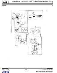
Component Guide<br />
1. Exhaust bend, sea-water cooled<br />
2. Turbo-compressor<br />
3. Coolant pipe<br />
4. Exhaust manifold, fresh-water cooled<br />
5. Pipe for oil discharge pump<br />
6. Oil dipstick<br />
7. Heat exchanger<br />
8. Filling, freshwater<br />
9. Alternator<br />
10. Draincock, sea-water<br />
11. Oil cooler<br />
12. Draincock, fresh-water<br />
13. Oil filter<br />
14. Oil pressure sender<br />
15. Oil pressure warner<br />
16. Draincock, sea-water<br />
17. Draincock, fresh-water<br />
18. Sea-water pump<br />
19. Sea-water filter<br />
20. Engine speed sender<br />
21. Injection pump<br />
22. Stop solenoid<br />
23. Oil filler cap<br />
24. Injector<br />
25. Glow plug<br />
26. Filter for crankcase ventilation<br />
27. Positive pressure valve for crankcase<br />
ventilation<br />
28. Air cleaner<br />
29. Inspection cover, injection timing<br />
30. Feed pump<br />
31. Fuel filter<br />
32. Engine number plate<br />
33. Fuel pipe connection for suction and<br />
return pipes
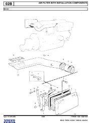
Drain off the cooling water and lubricating oil together<br />
with any fuel in the fuel filter and injection pump. Clean<br />
the engine externally.<br />
1. AQD40, TMD40, MD40: Take off the alternator drive<br />
belts. Remove the hose nipple and the ventilation pipe<br />
from the thermostat housing cover.<br />
2. AQAD40, TAMD40: Take off the alternator drive belts.<br />
Remove the ventilation pipe from the thermostat housing.<br />
Dismantling<br />
AQD40A, TMD40A, MD40A<br />
3a. TMD40, MD40: Take off the coolant pipes between the<br />
engine and the reversing gear.<br />
AQD40. Take off the pipe between the heat exchanger<br />
and the turbo-compressor.<br />
Remove the screws holding the heat exchanger and remove<br />
the heat exchanger by drawing it forward.<br />
AQD40B, TMD40B<br />
AQAD40, TAMD40<br />
3b. Take off the coolant pipes. Remove the screws holding<br />
the heat exchanger and remove the heat exchanger by<br />
drawing it forward.<br />
4a. Early prod. Remove the plastic cover from the front of<br />
the engine. Unscrew the plate on which the relays are<br />
mounted and remove the cooling water pipe which is located<br />
at the back of the plate.<br />
9
4b. Late prod. Remove all the connections of the cable harness<br />
and remove the electrical distribution box. Also<br />
remove the water pipe behind the distribution box.<br />
5. Disconnect the cables from the front and back glow plug.<br />
Disconnect the fuel leak-off line from the front injector.<br />
Disconnect the delivery lines from the injectors.<br />
6. Remove the inlet manifold, the rocker arm casing, the<br />
rocker arm bearing bracket and the pushrods.<br />
10<br />
7. AQAD40, TAMD40: Remove the pipe between the turbo<br />
and the after cooler. Loosen the bracket under the after<br />
cooler and remove the after cooler.<br />
8. Remove the oil pipes between the turbo-compressor and<br />
the engine block, also the coolant pipe between the exhaust<br />
manifold and the engine block.<br />
9. Remove the exhaust manifold together with the turbocompressor.<br />
Pull out the tube for the oil dipstick and the<br />
oil discharge pipe. Unscrew the front lifting eye. Take off<br />
the cylinder head.
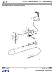
Fuel Pipes, Electrical Equipment<br />
10. Remove the fuel pipes and fuel hoses, the fuel filters with<br />
cover and the feed pump. Fit protective caps.<br />
11. Disconnect the cables from the generator, the starter<br />
motor, the stop solenoid, senders and warners.<br />
Unscrew the generator bracket and the tensioning device<br />
and lift out the generator.<br />
Remove the starter motor.<br />
12. Unscrew the cable support which is fixed in the injection<br />
pump and the oil trap for the crankcase ventilation. Take<br />
off the plate holding the relays together with the cable<br />
forms.<br />
Circulation Pump<br />
Remove the circulation pump.<br />
13. Remove the sea-water filter, the sea-water pump and the<br />
air cleaner together with the bracket. Remove the pipe<br />
between the sea-water filter and oil cooler. Unscrew the<br />
oil filter and discard it. Unscrew the bracket for the oil filter<br />
and lift it off together with the oil cooler.<br />
14a. Early prod. Unscrew the T-pipe holding the oil pressure<br />
warner and sender.<br />
14b. Late prod. Remove the oil pressure sensor and the oil<br />
pressure sender.<br />
11
Auxiliary Drive Gears<br />
15. Remove the belt pulley which is fitted on the crankshaft<br />
polygon hub. Release the polygon hub centre bolt and<br />
pull the hub off using puller 884533.<br />
16. Remove the cover over the auxiliary drive gear casing.<br />
Release the 4 bolts in the injection pump lifter. Remove<br />
the sea-water pump driver and the injection pump drive<br />
gear.<br />
17. Release the 3 bolts fastening the injection pump and lift<br />
the pump off. Release the centre bolt and pull off the<br />
camshaft drive gear with puller 2679.<br />
12<br />
18. Remove the idler gear and its bearing journal after loosening<br />
the 3 attaching bolts. Remove the crankshaft gear<br />
with puller 2658.<br />
Camshaft<br />
19. Remove the inspection covers and take out the valve<br />
tappets. Release the camshaft thrust washer and lift the<br />
camshaft out.<br />
Pistons, Connecting Rods<br />
20. Remove the sump, the oil pump with pipe and bracket.<br />
Remove the reinforcement plate, if fitted. Remove the<br />
pistons and connecting rods.<br />
NOTE! Be careful not to damage the piston cooling nozzles.
21. Extract the cylinder liners with the aid of a cylinder liner<br />
puller.<br />
Flywheel<br />
22. Remove the auxiliary drive gear casing, the connecting<br />
ring (for reversing gear or AQ-gear), the driving disc and<br />
the flywheel casing.<br />
Crankshaft<br />
23. Remove the crankshaft, noting that the main bearing<br />
caps are numbered. Remove the piston cooling nozzles.<br />
13
Cylinder Head<br />
1. Disassembling<br />
A. Remove the electric wiring plate and the glow plugs. Remove<br />
the injectors and fit protective caps to the tips of<br />
the injector nozzles.<br />
B. Remove the valve springs and valves with the aid of a<br />
valve spring clamp. Place the valves in order in a valve<br />
stand. Remove and discard the rubber seals for the inlet<br />
valves.<br />
2. Cleaning and Inspection<br />
Clean all the parts. Pay particular attention to the oil and<br />
coolant channels. Check for leakages by pressure testing.<br />
Check the plane of the cylinder head with a steel rule.<br />
Should the cylinder head be out of plane in excess of 0,10<br />
mm within a measuring length of 100 mm or 0,20 mm within<br />
the total length of the cylinder head, the cylinder head must<br />
be ground to plane.<br />
Grinding Flat<br />
(Early prod. engines with removable inserts).<br />
Remove the inserts from the chambers and turn down the<br />
lower ends (surface nearest the piston) by the same amount<br />
as the cylinder head is ground down. After being ground<br />
down flat, the height of the cylinder head must not be less<br />
than 86.7 (3.41339 in). Check that the inserts are flush with<br />
respect to the surface of the cylinder head within ±0.05 mm<br />
(0.00197 in). Check the dimension A, see point 5.<br />
14<br />
Overhaul<br />
3. Cylinder Head – Pressure Testing<br />
A. Plug all coolant holes with sealing washers part-no 6531.<br />
Use bolt part-no 955353 and nut part-no 955784 19 pcs<br />
of each, to tighten the sealing washers.<br />
B. Attach the connection washer part-no 6532 to the end of<br />
the cylinder head and connect the pressure testing device<br />
part-no 6662. Use the gasket of the water pipe plus<br />
4 bolts part-no 955295 for the connection washer.<br />
C. Tighten the reduction valve until the pressure gauge indicates<br />
100 kPa (1 kp/cm2 ).<br />
D. Lower the cylinder head in water to facilitate the finding<br />
of possible leakages.<br />
E. After the pressure testing, the cylinder head should be<br />
dried with compressed air.<br />
4. Valve Guides<br />
A. Check the valve guides for wear by inserting a new<br />
valve. Measure the clearance with the aid of a dial<br />
gauge. Change the guides if necessary.<br />
Wear Limits<br />
Inlet valve, max. clearance .................... 0.15 mm 0.00951 in<br />
Exhaust valve, max. clearance .............. 0.17 mm 0.00669 in
A = 18 mm (0.70866 in)<br />
B. Press out the valve guides using drift 2818. Oil the new<br />
guides externally and press them into position with tool<br />
5028. The tool should be pressed right down against the<br />
cylinder head. Ream the guides if necessary.<br />
5. Valves<br />
Grind the valves on the valve grinding machine. The angle<br />
(D) should be 29.5° for the inlet valve and 44.5° for the exhaust<br />
valve. If the thickness of the edge of the disc after<br />
grinding is less than 1.5 mm (0.05906 in) for an inlet valve or<br />
1.3 mm (0.05118 in) for an exhaust valve, the valve should<br />
be rejected. Valves with bent stems should also be rejected.<br />
If necessary, grind the surface on which the rocker arm<br />
bears.<br />
A (New valve)<br />
in: min. 1.1 mm (0.04331 in)<br />
max. 1.8 mm (0.07087 in)<br />
out: min. 0.85 mm (0.03346 in)<br />
max. 1.55 mm (0.06092 in)<br />
B in: 1.38–2.8 mm (0.0543–0.11024 in)<br />
out: 1.3–2.6 mm (0.05118–0.10236 in).<br />
C in: 30°, out 45°<br />
D in: 29.5°, out 44.5°<br />
6. Valve Seats<br />
Mill or ream the valve seats. The angle (C) should be 30° for<br />
the inlet and 45° for the exhaust. (Check the valve guides<br />
before machining the seats, and replace them if necessary).<br />
The width of the sealing surface should be 1.3–2.8 mm<br />
(0.05118–0.11024 in) for the inlet and 1.3–2.6 mm (0.05118–<br />
0.10236 in) for the exhaust. Replace the valve seats when<br />
the dimension (A), measured with a new valve, exceeds 1.8<br />
mm (0.07087) for the inlet or 1.55 mm (0.06102 in) for the exhaust.<br />
A new seat should be ground down so that the dimension<br />
(A) is min. 1.1 mm (0.04331 in) for the inlet or 0.85 mm<br />
(0.03346 in) for the exhaust.<br />
Replacing Valve Seats<br />
A. Remove the old seat by grinding two notches as shown<br />
in the diagram. Crack the seat with a chisel.<br />
B. Machine the seat recess to the correct dimension, see<br />
”Technical Data”. Cool the new seat down in CO snow 2<br />
to about 140°F (60°C), and warm up the cylinder head<br />
by rinsing it with hot water. Press the seat in with a drift.<br />
Machine the seat so that the height, angle and width are<br />
correct.<br />
15
7. Valve Springs<br />
Check the valve spring lengths, both unloaded and loaded.<br />
Length without load ................................... 46 mm 1.81102 in<br />
Length with load<br />
267–312 N (27.2–31.8 kp) .......................40 mm 1.5748 in<br />
Length with load<br />
766–851 N (78.2–86.8 kp) ..................... 30 mm 1.18110 in<br />
8. Rocker Arm Mechanism<br />
Dismantle the rocker arm mechanism and clear the parts.<br />
Check the shaft & the bushes for wear. If the bushes need to<br />
be changed, the tool 1867 is used for pressing out and in.<br />
(Ensure that the oil hole in the bush coincides with the hole in<br />
the rocker arm). After having been pressed in, the bushes<br />
should be reamed to give an accurate running fit.<br />
Check whether the rocker arm surface which bears on the<br />
valve is worn concave. Minor adjustments can be made with<br />
the valve griping machine. Oil the shaft and fit the parts.<br />
16<br />
9. Injectors<br />
When an injector is tested, the fuel should come out as a<br />
properly directed mist, see the illustration. The opening pressure<br />
is adjusted by unscrewing the injector and taking it<br />
apart, when the adjusting washer (1) can be replaced by a<br />
washer of suitable thickness.<br />
10. Assembling the Cylinder Head<br />
Clean the cylinder head. Oil the valve stems and fit the<br />
valves, not forgetting the sealing rings for the inlet valves. Fit<br />
the glow plugs and the plate for the electrical wiring. Fit the<br />
injectors together with new steel and copper washers. Do<br />
not tighten the injectors.
Cylinder Block<br />
11. Cleaning, Inspection<br />
Remove all core plugs and clean the cylinder block thoroughly.<br />
Check that all channels are free from deposits and<br />
that there are no cracks in the block. Refit the core plugs using<br />
a sealing compound.<br />
12. Pistons, cylinder liners<br />
The pistons and liners are classified and marked with a letter.<br />
A piston which is marked with a D must thus only be fitted<br />
into a liner with the same letter. Check the pistons and<br />
liners for damage before making any measurements.<br />
Class Cylinder diameter<br />
C 92.00–92.01<br />
3.54331–3.54370 in<br />
D 92.01–92.02<br />
3.54370–3.54409 in<br />
E 92.02–92.03<br />
3.54409–3.54448 in<br />
B. Measure the cylinder liner diameter at a number of points<br />
round the circumference and at a number of different<br />
heights between the top and bottom dead-centre positions<br />
(B and C).<br />
Change the piston and the liner if the wear is as much as<br />
0.25–0.30 mm (0.00984–0.01181 in).<br />
Measure the piston diameter (A) at right angles to the<br />
gudgeon pin and 15 mm (0.59055 in.) from the bottom of<br />
the piston. Calculate the maximum and minimum piston<br />
clearance (the max. and min. liner diameter minus the<br />
piston diameter).<br />
Piston clearance (new parts): 0.08–0.12 mm. 0.00315–<br />
0.00472 in.<br />
C. Measure the piston ring gap on the new rings. If the liner<br />
is not new, the check should be made with the ring in the<br />
bottom dead-centre position.<br />
The gap should be:<br />
Compression rings: 0.40–0.65 mm 0.01515–0.02559 in<br />
Scraper rings: 0.25–0.40 mm 0.00984–0.01575 in<br />
D. Measure the clearance of the piston rings in their<br />
grooves.<br />
NOTE! The upper ring should be flush with the surface<br />
of the piston at the point of measurement, see illustration.<br />
The clearance should be:<br />
Upper compression rings:<br />
0.08–0.13 mm 0.00315–0.00512 in<br />
Lower compression rings:<br />
0.07–0.10 mm 0.00276–0.00394 in<br />
Scraper rings:<br />
0.04–0.07 mm 0.00157–0.00276 in<br />
17
13. Connecting Rods<br />
A. Check the connecting rods for straightness and twist.<br />
B. Check the connecting rod bushings, using the gudgeon<br />
pins as gauges. There should be no noticeable play. If it<br />
is necessary to replace the bushings, drift 6271 should<br />
be used for pressing out and in. Ensure that the oil hole<br />
in the bushing lines up with that in the connecting rod.<br />
Ream the new bushings. When the fit is correct, an oiled<br />
gudgeon pin should slide slowly though the bushing under<br />
its own weight.<br />
18<br />
14. Crankshaft<br />
Measure the big-end journals and the main bearing journals.<br />
The out-of-round must not exceed 0.04 mm (0.00157 in) and<br />
the taper should not exceed 0.05 mm (0.00197 in). If these<br />
values are exceeded, the crankshaft should be ground to a<br />
suitable undersize. (See ”Technical Data”).<br />
15. Camshaft<br />
Check the camshaft for wear on the cams and bearing races.<br />
Also check the wear on the bearing. The bearings are<br />
pressed into their recesses and must be line milled after<br />
pressing in.<br />
Max. allowable wear on races or bearings 0.05 mm (0.00197<br />
in).<br />
16. Oil Pump<br />
A. Remove the idler. Pull off the drive gear with puller 6273.<br />
Remove the key and the brass washer.
B. Unscrew the bolts holding the pump housing. Press the<br />
housing loose by screwing the bolts in from the front<br />
side. Remove the pump gear.<br />
C. Check the housing for scoring and wear. Check the seal<br />
between the bracket and the pump housing. If leakage<br />
has occurred, the surfaces will be blackened. The bushings<br />
should be changed if the radial play between the<br />
shaft and the bushing is 0.15 mm (0.00591 in) or more.<br />
The new bushings should be reamed to give an accurate<br />
running fit with the housing bolted tightly onto bracket.<br />
The idler should be replaced if the radial clearance exceeds<br />
0.20 mm (0.00787 in). Check the pump gear for<br />
wear on the tooth flanks, external diameter and end faces.<br />
Check the end play and the tooth flank clearance.<br />
D. Oil the parts. Fit the pump gear and bolt the housing on. Fit<br />
the brass washer and the key.<br />
Press the drive wheel on so that a 0.05 mm (0.00197 in)<br />
feeler gauge fits accurately and evenly between the wheel<br />
and the brass washer.<br />
17. Sea-Water Pump<br />
A. Remove the cover and prise out the impeller using two<br />
screwdrivers. (Place some kind of protection under the<br />
screwdrivers so that the housing is not damaged). Turn<br />
the pump over and remove the lock ring. Turn the pump<br />
back again and press out the shaft, the bearings and the<br />
sealings.<br />
B. Grease the new bearings and press them into the shaft<br />
so that they fit right over the thickest part of the shaft.<br />
C. Replace the old cam disc by the new one. (MD40,<br />
AQD40, TMD40) Fig. 17E. Grease the sealing rings and<br />
press them into the housing with the lips pointing in opposite<br />
directions; use tool 884347. Place the O-ring between<br />
the two sealing rings.<br />
Pass the shaft down into the housing ensuring that the<br />
O-ring fits onto the shaft. Press the shaft and the bearings<br />
into the housing with tool 884347.<br />
(AQAD40, TAMD40), Fig. 17F. Mount the sealings in the<br />
housing. Press the shaft and the bearings into the housing<br />
with tool 884347.<br />
19
D. Fit the lock ring, the impeller and the sealing washers. Fit<br />
the cover together with a new gasket.<br />
E. MD40, TMD40, AQD40<br />
F. TAMD40, AQAD40<br />
20<br />
18. Circulation Pump<br />
A. Press the complete shaft including the impeller out of the<br />
pump housing. Loosen the 4 bolts and take off the driver.<br />
Take off the lock ring and prise the belt pulley loose with<br />
two screwdrivers.<br />
Knock out the inner bearing and the shaft seal with the<br />
aid of a small drift.<br />
Clean the housing and the belt pulley. Knock the bearing<br />
out of the belt pulley.
B. Pack the bearings with heat-resistant ball-bearing<br />
grease. Fill the space with the bearing with grease.<br />
Press the bearing into the belt pulley. Press the bearing<br />
into the pump housing with the aid of tool 2268 (turn the<br />
sealed side of the bearing towards the water).<br />
C. Place the deflector ring on the bearing and press the<br />
shaft seal on with tool 2270.<br />
NOTE! The carbon ring and the ceramic ring in the seal<br />
must not come into contact with grease or be touched<br />
with the fingers.<br />
D. Place the ceramic seal ring on the impeller and insert the<br />
shaft through the seal. Make sure that the deflector ring<br />
is correct. Press the shaft in so that there is a clearance<br />
of 0.8 mm (0.3150 in) between the impeller blades and<br />
the pump housing.<br />
19. Heat Exchanger, Aftercooler<br />
AQD40A, TMD40A, MD40A. Remove the cover of the thermostat<br />
housing. Remove the housing and pull out the heat<br />
exchanger insets.<br />
Heat exchanger<br />
After cooler<br />
AQAD40, TAMD40: Remove the cover and pull out the insert.<br />
Rinse and thoroughly clean the parts. If leakage is suspected,<br />
the insert can be pressure tested with i.e. air or kerosene,<br />
pressure: 0,2 MPa (2 kp/cm2 ). (28.4 lbf/in2 ).<br />
NOTE! Follow valid safety regulations.<br />
Check that the thermostats open at the correct temperature.<br />
Fit the parts in the reverse order, using new O-rings and a<br />
new gasket. Grease the insert connections with water resistant<br />
grease before re-assembling.<br />
21
20. Oil Cooler<br />
From and including engine no. 1070, the oil cooler insert can<br />
be removed for cleaning. Removing the end cover, replace<br />
the screws and screw in approx 5 mm (0.2”). Dismantle the<br />
zinc electrode. Stand the oil-cooler on the screws, ensure<br />
that it rests upon all the screws. Tap with the help of the tool<br />
884635 to loosen the insert.<br />
Remove the insert and take off the two O-rings. Wash the<br />
insert, use a brush which can be pushed into the tubes. Also<br />
clean the housing. Check the zinc electrode and if the length<br />
is less than 20 mm (0.7874 in) this should be replaced. Fit<br />
new O-rings and push the insert into the housing. Fit the end<br />
cover using a new gasket.<br />
Engines with lower number than 1070: Remove the end cover<br />
and wash the insert with a brush which can be pushed<br />
into the tubes. Flush water side and oil side respectively.<br />
22<br />
Pressure Testing<br />
Remove the oil cooler from the filter bracket. Make a plate to<br />
cover the two holes in the housing. Provide the plate with a<br />
connection for compressed air or similar. Bolt the plate into<br />
the housing, using sealing rings. Make a pressure test with<br />
approx. 0.7 MPa (7 kp/cm2 ) 100 lbf/in2 .<br />
NOTE! Follow valid safety regulations.<br />
There are two positive pressure valves installed in the oilfilter<br />
bracket. The rear for the piston cooling (opening pressure<br />
2,2–3,0 kp/cm 2 /31–42 psi.) and the forward for the engine oil<br />
pressure 4,2–5,0 kp/cm 2 /60–71 psi.)
Turbo-Compressor<br />
In the event of excessive exhaust smoke or loss of engine<br />
power, faulty action of the turbo-compressor is to be suspected.<br />
The supercharging pressure should then be<br />
checked. When speed slowly decreases the bottom of the<br />
boat should also be examined and, if necessary, cleaned.<br />
AQD40, TMD40<br />
AQAD40, TAMD40<br />
22. Checking the Supercharging<br />
Pressure<br />
A. Connect a pressure gauge to the measuring connection<br />
on the intake manifold (see illustration).<br />
Supercharging pressure at different<br />
temperatures.<br />
A. Supercharging pressure measured<br />
B. Correction curves<br />
C. Temperature of intake air<br />
B. Measure the supercharging pressure under full load and<br />
at full throttle whilst the engine speed passes relatively<br />
slowly through a suitable speed, e.g. 56.7 r/s (3.400 r/m)<br />
for B-power engines or 46.6 r/s (2.800 r/m) for C-power<br />
engines, see the Supercharging Pressure Diagram under<br />
”Technical Data”. The supercharging pressure<br />
should not be less than the specified minimum value.<br />
Check the engine speed with a hand tachometer.<br />
NOTE! It is important to maintain full loading long enough<br />
to enable the pressure to stabilise if results are to be correct.<br />
Also note that the pressure varies with the temperature<br />
of the intake air, as shown in the diagram below.<br />
The supercharging pressure is given at +20° (68°F),<br />
which implies that the measured pressure must be corrected<br />
as shown in the diagram if the intake air is not at<br />
this temperature when the measurement is made. Example:<br />
A measured pressure of 80 kPa (0.8 kp/cm2 = 11.3<br />
lbf/in2 ) measured at –10°C (14°F) corresponds to 70 kPa<br />
(0.7 kp/cm2 = 9.9 lbf/in2 ) at +20°C (68°F), i.e. the pressure<br />
decreases as the temperature rises, due to reduced<br />
air density.<br />
23
23. Measures to be carried out when the<br />
Supercharging Pressure is too low<br />
A. Air intake, air cleaner<br />
Check that the air intake is not blocked. Check the air cleaner<br />
and replace it if necessary.<br />
B. Leakage<br />
Check for leakage between the turbo housing and bearing<br />
housing or between the compressor housing and the bearing<br />
housing. Also check the joint between the turbo compressor<br />
and the inlet manifold.<br />
C. Turbo-compressor<br />
Remove the air cleaner. Check that the compressor rotor is<br />
at rest and then see whether the rotor is stiff when turned by<br />
hand. If the rotor is difficult to turn, the compressor should be<br />
replaced or reconditioned.<br />
Measure the axial and radial clearances of the rotor unit. The<br />
radial clearance is measured on the turbine side (at the outer<br />
edge of the hub, see illustration).<br />
Max. allowable axial clearance: 0.16 mm (0.00630 in).<br />
Max. allowable radial clearance: 0.42 mm (0.01654 in).<br />
If the wear limits are reached, the turbo-compressor should<br />
be replaced or reconditioned.<br />
If no faults are found:<br />
Check whether the compressor section requires cleaning,<br />
see point D. Deposits of soot and oil can cause low supercharging<br />
pressure.<br />
24<br />
D. Cleaning<br />
The compressor section can be cleaned with the unit still on<br />
the engine, as follows:<br />
Remove the compressor housing. Clean the compressor<br />
housing, the compressor rotor and the bearing shield with an<br />
agent such as white spirit. Fit the compressor housing and<br />
remeasure the supercharging pressure.<br />
If the supercharging pressure is still too low the following<br />
checks should be made:<br />
E. Throttle Control<br />
Check that the throttle control can move the injection pump<br />
throttle arm to the maximum position.<br />
F. Injection Pump<br />
Check the injection angle and the high idle speed.<br />
If necessary, check the entire pump on a pump test bench.<br />
G. Feed Pressure<br />
If necessary, replace the fuel fine filter and clean the<br />
pre-filter. There must be no fuel leakage.<br />
H. Injectors<br />
Check the opening pressure and the spray pattern.<br />
I. Condition of engine<br />
Check the valve clearances and the compression pressure.<br />
If the supercharging pressure is still unsatisfactory, the compressor<br />
must be reconditioned or replaced.
Reconditioning<br />
All moving parts of the turbo compressor are separately balanced.<br />
This also applies to spare parts. A joint balancing after<br />
reconditioning may however be advantageous from the<br />
viewpoint of life time length.<br />
24. Disassembling<br />
A. Make line-up marks between the turbine housing (1), the<br />
compressor housing (7) and the bearing housing (3). Remove<br />
the turbine housing and the compressor housing.<br />
Clamp the turbine rotor and remove the compressor rotor<br />
lock nut (8). The position of the wheel should be<br />
marked in relation to the shaft.<br />
B. Remove the compressor rotor. Press the shaft out if the<br />
rotor is stuck.<br />
C. Remove the bearing end head (5) and press out the piston<br />
ring retainer (9). Remove the piston rings, the oil deflector<br />
plate (10), the thrust bearing (11) and the thrust<br />
washer (12). Lift the bearing housing (1) and the heat<br />
shield (2) from the shaft. Remove the piston rings (14)<br />
and the bushings (13).<br />
Clean the components thoroughly, take care not to damage<br />
them.<br />
25
25. Measuring, Inspection<br />
A. Turbine Rotor with Shaft, Compressor Rotor<br />
26<br />
Check that the rotors and the shaft are free from mechanical<br />
defects. The blades must not be worn or deformed.<br />
Blades must never be straightened, and any<br />
damaged parts must be replaced by new or reconditioned<br />
parts.<br />
Place the shaft on two supports located under the bearing<br />
positions, see illustration. Measure the out-of-truth of<br />
the shaft at about 20 mm (0.7874 in) from the threaded<br />
portion. Max. allowable out-of-truth: 0.007 mm (0.00028<br />
in).<br />
Check the diameters at the shaft bearing positions. Min.<br />
dia. 9.95 mm (0.39173 in). Check the width of the piston<br />
ring grooves in the shaft. The width should be max. 3.0<br />
mm (0.11811 in).<br />
B. Bearing housing, Compressor housing,<br />
Turbine housing<br />
Check the housing for cracks and other damage. Measure<br />
the diameters of the bushing recesses in the bearing<br />
housing. The diameter should be max. 16.064 mm<br />
(0.63244 in).<br />
C. Bushings<br />
Check the bearing surfaces for damage. Measure the<br />
internal and external diameters. Internal diameter, max:<br />
10.00 mm (0.3937 in). External diameter, min: 15.975<br />
mm (0.62895 in). Measure the lengths of the bushings.<br />
These should be min: 11 mm (0.43307 in). Note that the<br />
bushings should have a push fit in the bearing housing.<br />
B = Wearing Surfaces<br />
D. Piston Rings, Piston Ring Retainers<br />
Measure the width of the piston rings. This should be<br />
min: 1.2 mm (0.04724 in). Measure the width of the piston<br />
ring grooves in the piston ring retainer. The width<br />
must not exceed 3.0 mm (0.11811).<br />
E. Thrust Washer, Thrust Bearing<br />
Measure the thickness of the thrust washer. This should<br />
be min. 1.47 mm (0.5787 in). Check the wearing surfaces<br />
of the thrust bearing. The angle, as shown in the illustration,<br />
should not exceed 30°.
26. Assembling<br />
Lubricate all moving parts involved in the assembly<br />
process.<br />
A. Fit the bushing and lock rings on the turbine side of the<br />
bearing housing. Also fit the inner lock ring on the compressor<br />
side.<br />
Fit the heat shield (2) on the bearing housing.<br />
Clamp the hub of the turbine rotor (15) in a vice. Fit the<br />
piston rings (14) and carefully fit the bearing housing<br />
over the shaft.<br />
B. Fit the piston ring gaps 90° apart and at 45° with respect<br />
to the oil inlet (see illustration). Compress the rings so<br />
that they can be inserted in the bearing housing. After<br />
this, check that the heat shield turns easily.<br />
C. Fit the bushing and the external lock ring on the compressor<br />
side of the bearing housing. Fit the thrust washer<br />
(12), the thrust bearing (11) and the oil deflector plate<br />
(10). Fit the piston rings on the piston ring retainer (9).<br />
Arrange the piston ring gaps in the same way as on the<br />
turbine side and fit the retainer in the bearing end head<br />
(5).<br />
D. Apply Curil T to the sealing surfaces of the bearing end<br />
head and screw the head into the bearing housing.<br />
NOTE! The self-locking bolts (4) should be replaced by<br />
new ones. (If the old bolts are used, they should be secured<br />
with Loctite). Tightening Torque: 8 Nm (0.8 kpm)<br />
(5.8 ft/lbs).<br />
Heat the compressor rotor up to about 100°C and fit it<br />
into the shaft. Tighten nut (8), torque 10 Nm (1 kpm)<br />
(7.233 ft/lbs). Check the torque after the parts have<br />
cooled down.<br />
27
E. Fit the O-ring on the bearing end head and fit the compressor<br />
housing (7). Torque 7 Nm (0.7 kpm) (5.0 ft/lbs).<br />
Fit the turbine housing (1). Tightening torque: 8 Nm (0.8<br />
kpm) (5.8 ft/lbs).<br />
28<br />
27. Fitting the turbo-compressor<br />
A. Change the engine oil and the lubricating oil filter. Bearing<br />
damage in the turbo-compressor is almost always<br />
caused by sludge deposits in the engine lubricating system.<br />
The presence of sludge deposits can be checked<br />
by lifting off the rocker arm casing. If deposits are found,<br />
the complete lubrication system must be thoroughly<br />
cleaned before a new or reconditioned turbo-compressor<br />
is fitted.<br />
The correct grade of oil must be used (see ”Technical<br />
Data”), and oil changes must be carried out in accordance<br />
with the instruction book in order to keep the engine<br />
clean.<br />
Also check the delivery and return lines to the turbocompressor.<br />
B. Clean the intake line between the turbine and the air<br />
cleaner. If the compressor rotor has been damaged,<br />
pieces may still remain which can damage the new compressor<br />
rotor.<br />
C. Fit the turbo-compressor on the engine. After this, inject<br />
lubricating oil into the compressor bearing system before<br />
fitting the delivery oil line.<br />
D. Turn the engine over, with the stop button pushed in, until<br />
oil pressure is obtained. Then disconnect the upper oil<br />
pipe on the turbo-compressor and check that oil is coming<br />
out of it.
Use new gaskets, sealing rings, sealing washers and lock<br />
washers. Apply grease or oil to the sealing rings. (The cylinder<br />
liner sealing rings should be smeared with soap). Also oil<br />
the movable parts before fitting.<br />
1. Fit the cylinder liners into the block without sealing rings.<br />
Measure the liner height, dimension A in the illustration.<br />
The measurement should be made at four points on<br />
each liner. The height should be: 0.26–0.31 mm<br />
(0.01024–0.01220 in), but the difference between two adjacent<br />
liners should not exceed 0.02 mm (0.00079 in).<br />
Mark the liners so that they come in the same position in<br />
the final assembly.<br />
Pistons, Liners<br />
Early prod. Late prod.<br />
A = 133.0 mm 134.5 mm<br />
B = 131.0 mm 141.0 mm<br />
2. With effect from engine number 11900 altered cylinder<br />
liners and cylinder block have been introduced in production.<br />
These alterations have been made so that the<br />
liner can be installed more easily and also to reduce the<br />
risk of damage to the sealing rings.<br />
The new liners can be used on earlier engines but the<br />
earlier liners cannot be used on later engines.<br />
Assembling<br />
1 = Black with violet marking<br />
2 = Black<br />
3 = Black (this ring and ring groove has been<br />
introduced with engine no 2201)<br />
3. Lift the cylinder liners and fit the sealing rings as shown<br />
in the illustration. Smear the sealing rings and the lower<br />
guides in the block with soapy water. Fit the liner into the<br />
block. (Center the liners so that the upper guides enter).<br />
4. Install the cylinder liners, using mandrel part-no 6598<br />
and standard shaft part-no 2000.<br />
29
5. Fit all piston cooling nozzles.<br />
6. Fit the main bearings and the crankshaft (lubricate bearing<br />
surfaces with engine oil. Fit the two thrust washers in<br />
the engine block, one on either side of the middle main<br />
bearing. Check the axial clearance. It should be 0.10–<br />
0.31 mm (0.00394–0.01220 in).<br />
7. Fit the main bearing caps so that their numbering is correct.<br />
(No. 1 at the front). Tightening torque: See ”Technical<br />
Data”. Oil the threads.<br />
30<br />
8. Heat the pistons up to about 100°C (212°F). Fit the pistons<br />
and connecting rods so that the front markings on<br />
the pistons and the numbers on the connecting rods are<br />
as shown in the illustration.<br />
9. Fit the piston rings with the aid of piston pliers. The compression<br />
rings are marked ”Top”. The oil scraper ring<br />
can be fitted either side up. Fit the big-end bearing shells.<br />
Oil the pistons, the piston rings and the big-end bearings.<br />
Arrange the piston rings so that the gaps are about 120°<br />
apart.<br />
Fit the pistons so that the front markings point forward.<br />
Use assembly tool 5031.<br />
NOTE! If the pistons are pushed down too far, the cooling<br />
nozzles may be damaged.
10. Fit the big-end bearing caps so that their markings agree<br />
with those on the connecting rod. Oil the threads. Tightening<br />
torque: 113 Nm (11.3 kpm) (81.73 ft/lbs).<br />
Oil Pump<br />
11. If the engine has a reinforcement plate (2) the threads of<br />
the bolts must be dipped in anti-rust medium, part no.<br />
598177, 24 hours max before assembling. At assembling<br />
the bolts must be dripfree. Clean the mating surfaces<br />
carefully. Tightening torque 46±5 Nm.<br />
Screw the oil pump tight to the front main bearing. Fit<br />
new sealing rings in accordance with the illustration.<br />
NOTE! Two yellow sealing rings should be fitted to the<br />
end of the delivery pipe which is connected to the block.<br />
Screw the bracket for the suction pipe to main bearing<br />
No. 5. Screw tight the oil pipes. The reducing valve (1) is<br />
fitted between the suction pipe and the pump.<br />
Flywheel<br />
12. Fit a new sealing ring in the flywheel casing (grease the<br />
ring before the casing is fitted). Fit the flywheel casing<br />
and the auxiliary drive gear casing.<br />
Fit the flywheel. Tightening torque 105 Nm (10,5 kpm),<br />
75,95 ft/lbs. With effect from engine number 31816, 115<br />
Nm (11,5 kpm) 82 ft/lbs.<br />
NOTE! The flywheel is provided with a guide-sleeve,<br />
which must match the crankshaft. Fit the driving<br />
disc and the connecting flange. Fit the oil sump.<br />
Auxiliary Drive Gears<br />
All the gearwheels in the auxiliary drive which affect the<br />
timing are marked with punch marks.<br />
31
12a. Oil the camshaft bearings. Fit the camshaft, the distance<br />
ring and the thrust washer. Check the axial clearance.<br />
This should be 0.04–0.12 mm (0.00157–0.00472<br />
in).<br />
Clean carefully each valve tappet and apply molybdenum<br />
disulphide on the surface against the camshaft. Oil<br />
the holes in the cylinder block. Fit the valve tappets and<br />
the inspection covers.<br />
32<br />
Earlier prod. R = 4.7 mm Later prod. R = 6 mm<br />
12b. NOTE! Later production of engines have altered valve<br />
tappets and push rods. These may not be mixed with<br />
earlier production.<br />
13. Check that the key is fitted in the crankshaft. Fit the<br />
crankshaft gear using tool 6404.<br />
NOTE! Ensure that the gearwheel meshes with the oil<br />
pump gear.<br />
14. Fit the key into the camshaft. Heat the camshaft gear to<br />
about 100°C (212°F) and fit it on the shaft.<br />
Fit the idler gear with its bearing journal so that the markings<br />
agree. The angular position of the bearing journal is<br />
immaterial. Tightening torque: Idler gear 23 Nm (2,3 kpm)<br />
(16.636 ft/lbs). Secure the bolts with the lock washer,<br />
(only early prod.). Tighten the camshaft drive gear. Tightening<br />
torque: 80 Nm (8 kpm) (5.8 ft/lbs).<br />
15. Remove the cover from the side of the injection pump.<br />
Turn the pump so that the line-up marking is visible (A).<br />
Later production of engines have a marking on the carrier<br />
(B). Position the carrier marking in a way that it points<br />
obliquely upwards to the left (the marking then points towards<br />
number 1 pressure line connection). Fit the pump<br />
on the engine, not forgetting the O-ring on the flange. Do<br />
not tighten the nuts.
16. Fit the pump gear so that the markings agree.<br />
NOTE! Later production of the pump gear wheel carries<br />
markings for the 6-cylinder engine as well as for<br />
the 4-cylinder one. Screw the pump gear tight together<br />
with the driver.<br />
NOTE! The bolts are unevenly spaced so that the driver<br />
can only be fitted in one position. Tightening torque: 23<br />
Nm (2.3 kpm) (16.636 ft/lbs). Fit the driver for the<br />
sea-water pump.<br />
17. Fit a new sealing ring in the auxiliary drive gear casing<br />
cover. Saturate the sealing ring with oil and fit the cover<br />
together with a new gasket.<br />
18. Apply molybdenum disulphide to the end of the crankshaft.<br />
Heat the polygon hub up to about 100°C (212°F)<br />
and fit it into the shaft. If necessary, the hub can be<br />
pressed on with tool 6404. Fit the washer and the centre<br />
bolt. Tightening torque: 180 Nm (18 kpm) (130.2 ft/lbs).<br />
Fit the belt pulley. Tightening torque: 25 Nm (2.5 kpm)<br />
(18.00 ft/lbs).<br />
Circulation Pump<br />
19. Fit the circulation pump and the front lifting eye.<br />
20a. Early prod. Fit the T-tube which holds the oil pressure<br />
warner and sender.<br />
33
20b. Later prod. Install the oil pressure sensor and the oil<br />
pressure sender.<br />
Oil Cooler<br />
21. Fit the oil filter bracket and the oil cooler. Fit a new oil filter,<br />
see the instructions for the filter.<br />
Cylinder Head<br />
22. Place the cylinder head gasket and the cylinder head on<br />
the cylinder block. Moisten the cylinder head bolts with<br />
rust protecting medium. Item No. 282036 (or a mixture of<br />
75% Tectyl 511 and 25% kerosene). The bolts should be<br />
free from drip when fitted.<br />
NOTE! The bolts are phosphated and must not be<br />
cleaned with a wire brush.<br />
Tighten the cylinder head bolts in accordance with the<br />
tightening diagram in the following stages: 30, 90 and<br />
130 Nm (3, 9, 13 kpm), (21.7, 65.1, 94.0 ft/lbs).<br />
NOTE! The cylinder head bolts shall be tightened after<br />
the engine has been run for approx. 1 h. (warm or cold<br />
engine).<br />
34<br />
23. Fit the push rods and the rocker arm bearing bracket.<br />
Tightening torque: 23 Nm (2,3 kpm) (16.636 ft/lbs).<br />
A = Inlet B = Outlet<br />
24. Valve Adjustment<br />
A. NOTE! The valve clearance must not be adjusted with<br />
the engine running. Valve clearance for all valves, engine<br />
hot or cold: 0.40 mm (0.01575 in). Adjust the valve<br />
clearance for Cylinder No. 1 with the piston in the firing<br />
position. The valves on Cylinder No. 6 will then ”Rock”.<br />
B. Turn the engine over one third of a revolution on its correct<br />
direction of rotation and adjust the clearance on No.<br />
5 cylinder. (The valves in cylinder No. 2 will then<br />
”Rock”). Adjust the clearances for the other cylinders in<br />
the order of firing.<br />
Order of Firing<br />
Corresponding cylinder<br />
1 5 3 6 2 4<br />
whose valves ”Rock” 6 2 4 1 5 3
26. Adjustment of Injection Angle<br />
(The rocker arm casing, pressure pipes and the cover of the<br />
flywheel casing should be removed).<br />
A. Turn the engine in the correct direction of rotation until<br />
both the valves in cylinder No. 6 are ”rocking”. Rotate<br />
the engine backwards (against the direction of rotation)<br />
to 30° b.t.d.c.<br />
Remove the center bolt on the rear end of the injection<br />
pump, and fit the tool 884612 and an indicator instrument<br />
884151. Set the instrument to zero.<br />
B. Turn the engine in the direction of rotation until the reading<br />
of the indicators is 1 mm. Then the grading of the flywheel<br />
will show: MD40 0-1°, TMD40 2-3°, TAMD40 1–2°<br />
after TDC. If the injection angle requires altering: Rotate<br />
the engine back to 30° b.t.d.c. Unscrew the pump attachment<br />
nuts and rotate the pump clockwise (as seen<br />
from the front), if the injection is too retarded. If the injection<br />
is too advanced, rotate the pump anti-clockwise.<br />
Tighten the pump and repeat the measurement.<br />
Exterior Details<br />
26. Fit the pipe between the oil cooler and the sea-water filter.<br />
Note the spacer sleeve on the left hand fastening.<br />
Later production of engines have a bracket with<br />
clamp to hold the pipe.<br />
27. Fit the tube for the oil dipstick and the oil discharge pipe.<br />
Fit the exhaust manifold. Fit the turbo-compressor (Not<br />
MD40).<br />
28. Fit the coolant pipe between the exhaust manifold and<br />
the cylinder block. Fit the oil pipe between the turbocompressor<br />
and the cylinder block (Not MD40).<br />
35
29. Fit the rocker arm cover, the inlet manifold, the generator<br />
and the starter motor.<br />
30. AQAD40, TAMD40: Fit the aftercooler and the pipe between<br />
the turbo and the aftercooler.<br />
31a. Early prod. Fit the cooling water pipe between the cylinder<br />
head and the exhaust manifold (on the engine in the<br />
front.) Screw the pipe fast, also the plate which holds<br />
the relays. Fit the plastic casing. Screw the cable support<br />
fast and connect the cables.<br />
36<br />
31b. Late prod. Install the coolant pipe between the cylinder<br />
head and the exhaust manifold (at the front end of the<br />
engine). Install the electrical distribution box and connect<br />
the cables.<br />
32. Fit the filter bracket together with a new fuel filter. Fit the<br />
feed pump and all fuel pipes. Tighten the injectors. Tightening<br />
torque: 23 Nm (2.3 kpm), (16.630 ft/lbs).<br />
AQD40A, TMD40A, MD40A
AQAD40, TAMD40A, AQD40B, TMD40B<br />
33. Fit the heat exchanger.<br />
34. (AQD40, TMD40, MD40.) Fit and tension the alternator<br />
driving belts. Fit the hose between the heat exchanger<br />
and the oil cooler. Screw the ventilation pipe fast into the<br />
thermostat housing cover. Fit the coolant hoses and the<br />
coolant pipes.<br />
35. (AQAD40, TAMD40.) Fit and tension the alternator driving<br />
belts. Fit the hose between the aftercooler and the oil<br />
cooler. Screw the ventilation pipe fast into the thermostat<br />
housing. Fit the coolant hoses and the coolant pipes.<br />
36. (AQD40, TMD40, MD40.) Fit the air cleaner, the sea-water<br />
pump and the sea-water filter.<br />
37. (AQAD40, TAMD40.) Fit the air cleaner, the sea-water<br />
pump and the sea-water filter.<br />
38. Close all draincocks. Refill with oil and water. See ”Technical<br />
Data” for the grade and viscosity of the oil. Vent the<br />
fuel system, see point 39.<br />
Make a trial run on the engine and check all the points<br />
specified under delivery Service on the Guarantee Certificate.<br />
NOTE! The cylinder head bolts shall be tightened after<br />
the engine has been run for approx. 1 h. (warm or cold<br />
engine).<br />
37
39. Venting the Fuel System<br />
NOTE! Be on the lookout for fuel spillage. Exercise special<br />
care at the venting point.<br />
A. Open the vent screw on the fuel filter by about 4 turns.<br />
Pump fuel on with the aid of the hand pump until fuel<br />
comes out free from air bubbles. If the pump does not<br />
work properly, turn the engine over slightly so that the<br />
pump driving cam changes position. Close the vent<br />
screw.<br />
B. If the injection pump has been removed, this must also be<br />
vented. Pump with the hand pump for about half a<br />
minute; this automatically removes any air from the injection<br />
pump.<br />
Loosen the delivery pipe nuts on the injectors. Set the<br />
governor to full revolutions and turn the engine over with<br />
the starter motor until fuel comes out of the delivery<br />
pipes. Tighten up the delivery pipe nuts.<br />
38<br />
40. Adjusting the speed<br />
NOTE! The lead seals may only be broken by specially<br />
trained personnel.<br />
Max unloaded speed<br />
Warm the engine up. Then run the engine light at the maximum<br />
speed. Check that the throttle arm (1) pressed up<br />
against the adjusting screw (3). Check with the pump speed<br />
given in technical data.<br />
Low Idle<br />
Warm the engine up. Check the speed when the engine is<br />
running light at the lowest speed. The speed should be 600–<br />
700 r/m. If necessary, adjust with adjusting screw (2).<br />
In order to secure the attachment of the front engine supports<br />
to the engine block, we recommend that the four<br />
screws on each support are checked using a torque of 7.3<br />
kpm (73 Nm) (54 ft. lb).
INSTRUMENTPANEL<br />
ENGINE<br />
Wiring Diagram<br />
(Early Prod.)<br />
39
Flying bridge<br />
Instrument Panel<br />
1. Key switch<br />
2. Stop button<br />
3. Rev. counter<br />
4. Voltmeter<br />
5. Oil pressure gauge<br />
6. Temperature gauge<br />
7. Protective resistor<br />
8. Warning lamp, (glow plugs)<br />
9. Instrument lighting<br />
10. Alarm analyser<br />
11. Alarm<br />
12. Connector<br />
40<br />
Wiring Diagram<br />
(Early Prod.)<br />
Engine<br />
Cable Marking<br />
13. Battery<br />
14. Main switch<br />
15. Starter motor<br />
16. Charging regulator<br />
17. Alternator<br />
18. Oil pressure sender<br />
19. Rev. sender<br />
20. Temperature sender<br />
21. Glow plug<br />
22. Connector<br />
23. Glow current relay<br />
24. Fuse<br />
25. Stop solenoid<br />
26. Start relay<br />
27. Temperature warner (for alarm)<br />
28. Oil pressure warner (for alarm)<br />
Designation Colour mm 2 AWG<br />
A’ White 1.5 15<br />
A’’ Ivory 1.5 15<br />
A’’’ White 2.5 13<br />
B Black 1.5 15<br />
B’ Black 0.75 18<br />
B’’ Black 70 00<br />
C Red 6 9<br />
C’ Red 70 00<br />
C** Red 2.5 13<br />
D Grey 1.5 15<br />
F Yellow 1.5 15<br />
G Brown 1.5 15<br />
H’ Blue 2.5 13<br />
H’’ Blue 1.5 15<br />
H’’’ Blue 4 11<br />
I Green/Red 1.5 15<br />
I’ Green/Red 0.75 18<br />
J Green 1.5 15<br />
J’ Green 0.75 18<br />
J’’ Green 0.75 18<br />
J’’’ Green 6 9<br />
K Yellow/Blue 0.75 18<br />
K’ Yellow/Blue 1.5 15<br />
L Red/White 0.75 18<br />
M Blue/Red 0.75 18<br />
N White/Red 1.5 15<br />
Flying bridge<br />
1. Rev. counter<br />
2. Stop button<br />
3. Start button<br />
4. Warning lamp, charging<br />
5. Warning lamp, oil pressure<br />
6. Warning lamp, temperature<br />
7. Pull switch (spare)<br />
8. Instrument lighting<br />
9. Connector<br />
10. Electronic signal equipment<br />
11. Alarm analyser
Electrical Wiring Diagram<br />
(Late Prod.)<br />
Instrument Panel<br />
1. Voltmeter<br />
2. Oil pressure gauge<br />
3. Coolant temperature gauge<br />
4. Printed circuit card<br />
5. Push button<br />
6. Switch for instrument lighting<br />
7. Rev. counter<br />
8. Key switch<br />
9. Alarm<br />
41
42<br />
Engine<br />
Electrical Wiring Diagram<br />
(Late Prod.)<br />
1. Temp.<br />
2. Oil pressure-guard<br />
3. Oil pressure sender<br />
4. Temp. sender<br />
5. Sender rev. counter<br />
6. Start-relay<br />
7. Relay, glow-current<br />
8. Fuse<br />
Cable colour<br />
GR = Grey<br />
SB = Black<br />
BN = Brown<br />
LBN = Light brown<br />
R = Red<br />
PU = Purple<br />
GN = Green<br />
Y = Yellow<br />
W = White<br />
BL = Blue<br />
LBL = Light blue<br />
Wire areas in mm 2
Electrical Wiring Diagram<br />
(Late. Prod)<br />
1. Printed circuit card<br />
2. Rev. counter<br />
3. Switch for instrument lighting<br />
4. Push button<br />
5. Alarm<br />
6. Key switch<br />
Flying bridge<br />
43
Engine does<br />
not start<br />
X<br />
X<br />
X<br />
44<br />
9991867<br />
884533<br />
Engine stops Engine does<br />
not reach correct<br />
working<br />
speed on full<br />
throttle<br />
X<br />
X X<br />
X<br />
Fault Finding Table<br />
X X<br />
Engine runs irregularly<br />
or vibratesabnormally<br />
Engine becomesabnormally<br />
hot<br />
X<br />
Special Tools<br />
CAUSE OF TROUBLE<br />
Main switch not closed. Battery<br />
discharged. Break in cable or main<br />
fuse block. Faulty glow plugs.<br />
Fuel tank empty. Fuel cock closed.<br />
Fuel filter blocked.<br />
Water or impurities in fuel. Faulty<br />
injectors. Air in fuel system.<br />
Faulty rev. counter. Boat loaded<br />
abnormally. Air cleaner blocked.<br />
Fouling on boat bottom or outboard<br />
mechanism.<br />
Propeller damaged.<br />
Coolant level too low, V-belts broken<br />
or slipping.<br />
Obstruction in sea-water filter,<br />
cooling water intake, oil cooler,<br />
cooling jackets or heat exchanger.<br />
Sea-water pump impeller fault.<br />
Thermostats faulty.<br />
Drift for removing and fitting bushing in rocker lever<br />
Puller for polygon hub on crankshaft<br />
884635 Tool for removing oil cooler insert (from and<br />
including engine no 1070)
9992268<br />
9992270<br />
9992479<br />
9992658<br />
9996404<br />
9992679<br />
9992818<br />
9995028<br />
9995031<br />
9996271<br />
Drift for fitting bearing in circulation pump<br />
Drift for fitting seal in circulation pump<br />
Retainer for dial indicator when checking height of liner<br />
flanges above cylinder block face<br />
Puller for crankshaft gear<br />
Press tool for fitting crankshaft gear and polygon<br />
Puller for camshaft gear<br />
Drift for removing valve guides<br />
Drift for fitting valve guides<br />
Installing ring for piston<br />
Drift for removing and fitting gudgeon pin bushings<br />
45
46<br />
9996272<br />
9996273<br />
884347<br />
884602+<br />
884551+<br />
884231<br />
884612<br />
884151<br />
9996662<br />
9996532<br />
9996531<br />
Press tools (two) for cylinder liners when measuring<br />
height of cylinder liners<br />
Puller for oil pump drive gear<br />
Drift for fitting bearings and seal rings in seawater<br />
pump<br />
Plate for cylinder liner puller. Should be supplemented<br />
with yoke from 884551 {MD5) and screw and nut from<br />
884231 (MD21 -32)<br />
Holder for indicator instrument for injection angle<br />
measurement<br />
Indicator gauge<br />
Test pressure device for cylinder head<br />
Connection washer for test pressure cylinder head<br />
Sealing washers for test pressure cylinder head<br />
(19 pcs)
General<br />
Technical Data<br />
Type designation ................................................................................. AQD40, AQAD40, TAMD40<br />
TMD40, MD40,<br />
Number of cylinders ............................................................................ 6<br />
Cylinder diameter ................................................................................ 92.015 mm, 3.62264 in<br />
Stroke .................................................................................................. 90 mm, 3.54331 in<br />
Displacement, total .............................................................................. 3.59 dm3 , 220 in3 Compression ratio ............................................................................... 21:1<br />
Compression pressure at starter motor speed, 4 r/s (240 r/min) ........ 2.5 MPa (25 kp/cm2 ) 355 lbs/in2 Order of firing (No. 6 cylinder nearest flywheel) .................................. 1-5-3-6-2-4<br />
Direction of rotation (viewed from front) .............................................. Clockwise<br />
Output ................................................................................................. See applicable engine diagram<br />
Torque ................................................................................................. See applicable engine diagram<br />
Engine Power Governor Max<br />
lever overrun unloaded<br />
speed r/m speed r/m<br />
Pump settings ...................................................................... MD40A C-output 3000 3190–3290<br />
MD40A B-output 3600 3980–4080<br />
MD40A C-output 3000 3190–3290<br />
MD40A B-output 3600 3980–4080<br />
TMD40A B-output 3600 4000–4050<br />
TMD40A B-output 3600 3980–4080<br />
TMD40A B-output 3600 3900–4080<br />
TMD40A C-output 3000 3190–3290<br />
TMD40B B-output 3600 3980–4080<br />
TAMD40A B-output 3600 3980–4080<br />
TAMD40A C-output 3000 3190–3290<br />
TAMD40B B-output 3600 3980–4080<br />
TAMD40B C-output 3250 3730–3830<br />
Low idling ............................................................................................ 10–11.6 r/s (600–700 r/m)<br />
Weight, engine without outboard drive or reversing gear about ........... 400 kg 881.6 lbs (TAMD40, 440 kg, 968 lbs).<br />
AQD40, TMD40 AQAD40, TAMD40<br />
Supercharger Pressure<br />
Supercharging pressure (measured in the inlet manifold) at<br />
100 % load and full throttle and with an air temperature of<br />
plus 20°C. If the measurement is made at some other temperature,<br />
the measured pressure must be corrected in accordance<br />
with the diagram on page 23.<br />
Turbo-Compressor<br />
Curve 1 = Lowest supercharging pressure at an output in<br />
accordance with Curve C of the engine diagram.<br />
Curve 2 = Lowest supercharging pressure at an output in<br />
accordance with Curve B of the engine diagram.<br />
A considerably lower pressure is obtained at less than full<br />
output.<br />
Make and type (AQD40, TMD40) ........................................................ KKK K26-2470/10.7<br />
Make and type (AQAD40, TAMD40) .................................................... KKK K26-2664 GA 12.71<br />
Lubrication system .............................................................................. Pressure lubrication<br />
Cooling system ................................................................................... Fresh-water cooling<br />
Axial clearance, max ........................................................................... 0.16 mm (0.00630 in)<br />
Radial clearance, max. (compressor side) .......................................... 0.42 mm (0.01654 in)<br />
47
Cylinder Liners<br />
Type ..................................................................................................... Wet, replaceable<br />
Cylinder diameter (no oversizes available) ......................................... 92.015 mm, 3.54390 in<br />
Collar thickness .................................................................................. 9.20–9.23 mm, 0.36622–0.36740 in<br />
Depth of liner recess from cylinder block face .................................... 8.920–8.940 mm, 0.35118–0.35197 in<br />
Height of liner above cylinder block face, see illustration .................... 0.26–0.31 mm, 0.01024–0.01220 in<br />
Max. difference in height between adjacent liners ............................... 0.02 mm, 0.00079 in<br />
Pistons<br />
Material ................................................................................................ Light alloy with cast iron ring carriers<br />
Overall height ...................................................................................... 101.375–101.825 mm, 3.99114–4.00885 in<br />
Height from gudgeon pin centre to top of piston .................................. 66.575–66.625 mm, 2.62106–2.62303 in<br />
Piston clearance ................................................................................. 0.08–0.12 mm, 0.00315–0.00472 in<br />
Piston fitted in engine, height above cylinder block surface ................ 0.035–0.650 mm, 0.00137–0.02559 in<br />
Front marking ...................................................................................... Arrow pointing towards front end<br />
Piston Rings<br />
Compression rings, number ................................................................ 2<br />
Upper compression ring, height ........................................................... 2,5 mm, 0.09843 in<br />
Lower compression ring, height ........................................................... 2.478–2.490 mm, 0.94794–0.94844 in<br />
Oil scraper ring, number ...................................................................... 1<br />
Height .................................................................................................. 3.978–3.990 mm, 0.15661–0.15708 in<br />
Piston ring clearance in groove, axial:<br />
Upper compression ring, see diagram ................................................. 0.08–0.13 mm, 0.00315–0.00512 in<br />
Lower pressure ring ............................................................................ 0.07–0.10 mm, 0.00276–0.00394 in<br />
Oil scraper ring .................................................................................... 0.04–0.07 mm, 0.00157–0.00276 in<br />
Piston ring gap measured in cylinder liner:<br />
Compression rings .............................................................................. 0.40–0.65 mm, 0.0157–0.0256 in<br />
Oil ring ................................................................................................. 0.25–0.40 mm, 0.0098–0.0157 in<br />
Gudgeon Pins<br />
Clearance, gudgeon pin-connecting rod bushing ................................ 0.014–0.022 mm, 0.00055–0.00087 in<br />
Clearance, gudgeon pin-gudgeon pin hole .......................................... max. 0.008 mm, 0.00035 in<br />
Grip fit, gudgeon pin-gudgeon pin hole ................................................ max. 0.002 mm, 0.00008 in<br />
Gudgeon pin diameter ......................................................................... 35.000–35.004 mm, 1.37795–1.37811 in<br />
Connecting rod bushing, internal dia ................................................... 35.018–35.022 mm, 1.37866–1.37882 in<br />
Gudgeon pin hole dia. in piston ............................................................ 35.002–35.008 mm, 1.37803–1.37826 in<br />
Cylinder Head<br />
Height ............................................ 86.9-87.1 mm, 3.42136-3.42914 in<br />
48
Crankshaft with Bearings<br />
Crankshaft end float ............................................................................ 0.10–0.31 mm, 0.00394–0.01220 in<br />
Main bearings, radial clearance ........................................................... 0.04–0.09 mm, 0.00157–0.00354 in<br />
Main Bearing Journals<br />
Diameter, standard .............................................................................. 69.987–70.000 mm, 2.74788–1.75591 in<br />
Undersize 0.25 mm, 0.01 in ................................................................. 69.737–69.750 mm, 2.74204–2.74607 in<br />
0.50 mm, 0.02 in .................................................................................. 69.487–69.500 mm, 2.73220–2.73623 in<br />
0.75 mm, 0.03 in .................................................................................. 69.237–69.250 mm, 2.72586–2.72639 in<br />
With (A in figure) on crankshaft for pilot bearing with<br />
separate thrust washers:<br />
Standard .............................................................................................. 35.975–36.025 mm, 1.41634–1.418230 in<br />
Oversize 0.2 mm 0.00787 in<br />
(thrust washers 0.1 mm 0.00394 in oversize) .................................. 36.175–36.225 mm, 1.42421–1.42617 in<br />
Oversize 0.4 mm, 0.01575 in<br />
(thrust washers 0.2 mm 0.00787 in oversize) .................................. 36.375–36.425 mm, 1.43208–1.43403 in<br />
Big-End Journals<br />
Big-end bearings, radial clearance ...................................................... 0.034–0.078 mm, 0.00134–0.00307 in<br />
Length of bearing journals ................................................................... 38.95–39.05 mm, 1.53346–1.53740 in<br />
Diameter, standard .............................................................................. 56.487–56.500 mm, 2.22390–2.22441 in<br />
Undersize, 0,25 mm 0,01 in ................................................................ 56.237–56.250 mm, 2.21012–2.21063 in<br />
0.50 mm, 0.02 in ............................................................... 55.987–56.000 mm, 2.19685–2.20472 in<br />
0.75 mm, 0.03 in ............................................................... 55.737–55.750 mm, 2.18307–2.19094 in<br />
Main and Big-End Bearing Shells<br />
Main bearing shells Big-End bearing shells<br />
Thickness, standard ....................................... 2.970–2.979 mm, 1.724–1.733 mm,<br />
0.11683–0.11728 in 0.06787–0.06819 in<br />
Undersize, 0.25 mm, 0.01 in .......................... 3.095–3.104 mm, 1.849–1.858 mm,<br />
0.12185–0.12221 in 0.07280–0.07315 in<br />
0.50 mm, 0.02 in .......................... 3.220–3.229 mm, 1.974–1.983 mm,<br />
0.12677–0.12712 in 0.07771–0.07797 in<br />
0.75 mm, 0.03 in .......................... 3.345–3.354 mm, 2.099–2.108 mm,<br />
0.13169–0.13205 in 0.086264–0.08299 in<br />
Connecting Rods<br />
R = 3.9 mm<br />
Marked 1 to 6.<br />
End float, connecting rod – crankshaft ................................................ 0.15–0.30 mm, 0.00591–0.01181 in<br />
Dia. Big-end bearing shell recess ........................................................ 60.00–60.013 mm, 2.36220–2.36271 in<br />
Dia. Connecting rod bearing bushing recess ....................................... 39.000–39.039 mm, 1.53543–1.53697 in<br />
Dia. Gudgeon pin bushing ................................................................... See ”Gudgeon Pins’’<br />
49
Flywheel<br />
Flywheel ring gear ............................................................................... 115 teeth<br />
Camshaft<br />
Drive .................................................................................................... Gear<br />
Number of bearings ............................................................................. 7<br />
Dia. of bearing journals ........................................................................ 52.981–53.000 mm, 2.08586–2.08661 in<br />
End float .............................................................................................. 0.04–0.12 mm, 0.00157–0.00433 in<br />
Radial clearance ................................................................................. 0.025–0.063 mm, 0.00098–0.000248 in<br />
Checking camshaft setting (cold engine and valve clearance = 0)<br />
With flywheel at 10° after TDC, the inlet valve for<br />
No. 1 cylinder should have opened ...................................................... 2.1 mm, 0.08267 in<br />
Lift, inlet ............................................................................................... 7.26 mm, 0.28583 in<br />
exhaust ............................................................................................... 7.54 mm, 0.29685 in<br />
Camshaft Bearings<br />
Bearing diameter ................................................................................. 53.025–53.044 mm, 2.08759–2.08834 in<br />
Auxiliary Drive Gears<br />
Backlash ............................................................................................. 0.03–0.17 mm, 0.00118–0.00669 in<br />
Radial clearance of idler gear .............................................................. 0.03–0.09 mm, 0.00118–0.00354 in<br />
End float for idler gear ......................................................................... 0.03–0.15 mm, 0.00118–0.00591 in<br />
Shaft for idler gear, dia. ........................................................................ 54.940–54.970 mm, 2.16299–2.16417 in<br />
Bushing for idler gear, dia .................................................................... 55.000–55.030 mm, 2.16535–2.16653 in<br />
Number of Teeth: Crankshaft Gear..................................................... 33<br />
Idler Gear ............................................................... 41<br />
Camshaft Gear ....................................................... 66<br />
Drive gear for injection/sea-water pump ................. 66<br />
Valve System<br />
50<br />
Valve Lay-Out and Cylinder Numbering<br />
Valves, A = INLET, B = EXHAUST<br />
Valves Inlet Exhaust<br />
Disc diameter ................................................. 41.8 mm, 1.64567 in 35.7 mm, 1.40551 in<br />
Stem diameter ................................................ 7.955–7.970 mm, 7.925–7.940 mm,<br />
0.31319–0.31378 in 0.31200–0.31259 in<br />
Valve seat angle ............................................. 29.5° 44 5°<br />
Seat angle in cylinder head ............................ 30° 45°<br />
Clearance, (cold engine or at<br />
working temperature) ..................................... 0.40 mm, 0.01575 in 0.40 mm, 0.01575 in
Valve seats<br />
Valve seat Valve seat Recess<br />
Inlet Exhaust<br />
Diameter, standard (measurement A) ............. 43.064–43.080 mm 37.064–37.080 mm<br />
1.69543–1.69606 in 1.45921–1.45984 in<br />
Oversize ......................................................... 43.264–43.280 mm 37.264–37.280 mm<br />
1.70370–1.70393 in 1.46709–1.46771 in<br />
Height (measurement B) ................................. 7.3–7.35 mm 7.5–7.55 mm<br />
0.28740–0.28937 in 0.29528–0.29725 in<br />
Valve Seat Recess:<br />
Dia. standard (measurement C) ...................... 43.000–43.025 mm 37.000–37.025 mm<br />
1.69291–1.69350 in 1.45669–1.45767 in<br />
Oversize ......................................................... 43.200–43.225 mm 37.200–37.225 mm<br />
1.70078–1.70137 in 1.46456–1.46554 in<br />
Depth (measurement D) ................................. 10.5–10.8 mm 10.25–10.5 mm<br />
0.4134–0.4254 in 0.40354–0.4134 in<br />
Bottom radius of recess (measurement R) ...... 0.4–0.5 mm 0.4–0.5 mm<br />
0.01575–0.01969 in 0.01575–0.01969 in<br />
The distance between the valve disc and<br />
the cylinder head face should be ..................... 1.1–1.6 mm 0.85–1.35 mm<br />
0.04331–0.06299 in 0.03346–0.04348 in<br />
Valve Guides<br />
Length ................................................................................................. 59 mm 2.32283 in<br />
Internal dia. (fitted) ............................................................................... 8.000–8.015 mm, 0.31496–0.31555 in<br />
Replacement type ............................................................................... 8.000–8.022 mm, 0.31496–0.32362 in<br />
Height above cyl. head spring plane ....................................................<br />
Clearance, valve stem - valve guide:<br />
18 mm, 0.70866 in<br />
Inlet valves .......................................................................................... 0.030–0.060 mm, 0.00012–0.00024 in<br />
Exhaust valves ................................................................................... 0.060–0.090 mm, 0.00024–0.00035 in<br />
Valve Springs<br />
Length unloaded .................................................................................. 46 mm, 1.81102 in<br />
Length with loading of: 267–312 N (27.2–31.8 kp) 60–70 lbs .............. 40 mm, 1.57480 in<br />
Length with loading of: 767–852 N (78.2–86.2 kp) 170–190 lbs ........... 30 mm, 1.18110 in<br />
Length fully compressed, max ............................................................. 28.8 mm, 1.13386 in<br />
Rocker Arm Mechanism<br />
Rocker arm bushing, dia. after pressing in and machining .................. 22.020–22.041 mm, 0.86732–0.86775 in<br />
Lubricating System<br />
Oil pressure, hot engine, operating speed, lubricating oil .................... 0.42–0.5 MPa (4.2–5 kp/cm 2 )<br />
59.7–71.1 lbf/in<br />
Oil pressure, hot engine, operating speed, piston; cooling oil .............. 0.22–0.3 MPa (2.2–3 kp/cm 2 )<br />
31.3–42,6 lbf/in 2<br />
Oil quality in accordance with API-system .......................................... CD (For Service DS)<br />
Oil viscosity, above +10°C 50°F ......................................................... SAE 20W/30 1)<br />
under +10°C 50°F ............................................................................... SAE 10W 2)<br />
1) Volvo Penta CD Oil, Double Grade.<br />
2) Volvo Penta CD Oil, Single Grade<br />
51
Oil capacity, including oil cleaner:<br />
No engine inclination ........................................................................... 11 dm 3 (litre) 2.42 imp.gal, 2.9 US gal<br />
15° engine inclination .......................................................................... 10.5 dm 3 (litre) 2.3 imp.gal. 2.77 US gal<br />
Lubricating oil pump, type .................................................................... Gear<br />
End float, pump gear ........................................................................... 0.07–0.15 mm0.00276–0.00591 in<br />
Backlash, pump gear .......................................................................... 0.15–0.35 mm0.00591–0.01378 in<br />
Dia., idler gear bearing sleeve ............................................................. 55.03–55.06 mm, 2.1665–2.1677 in<br />
Bushing for idler gear .......................................................................... 54.07–55.00 mm, 2.12874–2.16535 in<br />
Radial clearance for idler gear ............................................................. 0.03–0.09 mm, 0.00118–0.00354 in<br />
Dia., oil pump bushings ....................................................................... 16.016–16.034 mm, 0.63055–0.63126 in<br />
Clearance, thrust washer – oil pump drive gear .................................. 0.02–0.08 mm, 0.00079–0.00315 in<br />
Number of teeth on oil pump drive gear ............................................... 39<br />
Oil pump idler ...................................................................................... 36<br />
Crankcase ventilation<br />
Valve opens at ..................................................................................... 0,8 kPa (0.008 kp/cm 2 ), 0.114 lbf/in 2<br />
Fuel System<br />
Direction of rotation of injection pump, seen from the front .................. Anti-clockwise<br />
Order of injection ................................................................................. 1-5-3-6-2-4<br />
Low idling ............................................................................................ 10–11.6 r/s (600–700 r/m)<br />
High idling B-output ............................................................................. 66.6–67.5 r/s (4000–4050 r/m)<br />
C-output .............................................................................................. 53.2–54.8 r/s (3200–3300 r/m)<br />
Feed Pressure ..................................................................................... 14.7–27.5 kPa (0.15–0.28 kp/cm 2 )<br />
2.13-4.98 lbf/in 2<br />
Injection Pump<br />
Make, type ........................................................................................... Bosch EP/VE 6/11 F<br />
Setting ................................................................................................. MD40 0-1°, TMD40 2-3°,<br />
TAMD40 1-2° after TDC with 1 mm plunger lift<br />
Feed Pump .......................................................................................... S.E.V. 70 VE<br />
Fuel Filter<br />
Type designation ................................................................................. FJ/DBR 1 W6/225<br />
Injectors<br />
Nozzle Holders, make and type .......................................................... KBE 36 S 2/13<br />
Nozzles ............................................................................................... DN 0 SD 193<br />
Type of Nozzle .................................................................................... Pintle Nozzle<br />
Injector compl. number marking ........................................................... 0 432 297 032<br />
Opening pressure ................................................................................ 17.7 MPa (175 kp/cm2 , 2489 lbf/in2 )<br />
Adjusting pressure (new spring) ......................................................... 18.0–18.8 MPa (183–192 kp/cm2 )<br />
2602.8-2730.8 lbf/in2 Cooling system<br />
Type ..................................................................................................... Overpressure<br />
Capacity, including heat exchanger and separate expansion tank,<br />
about (AQ40, TMD40, MD40) .............................................................. 21 dm 3 4.6 imp.gal. 5.5 US gal.<br />
Capacity, including heat exchanger and separate expansion tank,<br />
about (AQAD40, TAMD40) .................................................................. 23 dm 3 5.0 imp.gal. 6.6 US gal.<br />
Thermostats<br />
Type ..................................................................................................... Wax<br />
Number ............................................................................................... 2<br />
The thermostat with an air valve should open at ................................. 68–72°C, 154.4–161.6°F<br />
Fully open at ........................................................................................ 78–82°C, 172.4–179.6°F<br />
The thermostat without an air valve should open at ............................ 74–78°C, 165.2–172.4°F<br />
Fully open at ........................................................................................ 84–88°C, 183.2–190.4°F<br />
52
Electrical System<br />
System voltage ................................................................................... 12 V<br />
Battery capacity .................................................................................. 114 Ah<br />
Density of battery electrolyte:<br />
Fully charged battery ........................................................................... 1.275–1.285<br />
Battery to be recharged at ................................................................... 1.230<br />
Alternator<br />
Voltage/max. current ............................................................................ 14 V/50 A<br />
Output ................................................................................................. 700 W<br />
Starter Motor<br />
Output ................................................................................................. 2.5 kW (3.4 hp)<br />
Brush length ........................................................................................ min. 10 mm 0.3937 in<br />
Brush spring force ............................................................................... 20–25 N (2–2.5 kp) 4.41–5.51 lb<br />
Glow plug Bosch ................................................................................. RSK<br />
Wear Tolerances<br />
Cylinder Head<br />
Height .................................................................................................. min. 86.7 mm, 3.4134 in<br />
Cylinders<br />
Cylinder liners and pistons must be replaced when<br />
wear amounts to .................................................................................. 0.25–0.30 mm, 0.0098–0.0118 in.<br />
Crankshaft<br />
Permissible out-of-round on main and big-end bearing journals, max. . 0.04 mm, 0.001575 in<br />
Max. permissible taper on main and big-end journals .......................... 0.05 mm, 0.00197 in<br />
Max. end float on crankshaft ............................................................... 0.40 mm, 0.01575 in<br />
Valves<br />
Valve stems, max. permissible wear ...................................................<br />
Max. permissible clearance between valve stem and valve guide<br />
0.02 mm, 0.00079 in<br />
Inlet valves .......................................................................................... 0.15 mm, 0.00591 in<br />
Exhaust valves ................................................................................... 0.17 mm, 0.00669 in<br />
The valve edge should be, min. inlet .................................................... 1.5 mm, 0.05906 in<br />
exhaust ...............................................................................................<br />
The valve seat may be ground until the distance from the<br />
valve disc (new valve) to the cylinder head surface is:<br />
1.3 mm, 0.05118 in<br />
Inlet ...................................................................................................... 1.8 mm, 0.07087 in<br />
Exhaust ............................................................................................... 1.55 mm, 0.06103 in<br />
Camshaft<br />
Max. permissible wear ......................................................................... 0.05 mm, 0.00197 in<br />
Bearings, max. permissible wear ........................................................ 0.05 mm, 0.00197 in<br />
53
Tightening Torques<br />
Nm (kpm) ft lbs<br />
Cylinder head bolts* ....................................... 130 (13) 94.0<br />
Tightening diagram, Cylinder Head Bolts.<br />
* Note! The bolt threads should be moistened with rust proofing medium (detail number 282036) before being fitted. The bolts<br />
should be tightened in accordance with the diagram in stages, the tightening torques for these stages being 30, 90 and 130<br />
Nm (3, 9, 13 kpm) 22, 65, 94 ft/lbs.<br />
NOTE! The bolts should be re-tightened after 1 h test run (warm or cold engine).<br />
Nm (kpm) ft lbs<br />
Main bearings ................................................ 180, 140* (18) (14)* 130.2 (101.2)*<br />
Big-end bearings ............................................ 113 (11.3) 81.7<br />
Rocker arm shaft ........................................... 23 (2.3) 16.6<br />
Thrust washer, camshaft bearings ................. 23 (2.3) 16.6<br />
Camshaft gear ............................................... 80 (8) 57.8<br />
Bearing journal for idler gear,<br />
auxiliary drive gears ....................................... 23 (2.3) 16.6<br />
Engine speed sender ..................................... 40 (4) 28.9<br />
Oil filter with oiled sealing ring ........................ 25 (2.5) 18.0<br />
Lubricating oil pump bracket .......................... 23 (2.3) 16.6<br />
Rocker arm cover .......................................... 10 (1) 7.2<br />
Auxiliary drive gear casing ............................. 20 (2) 14.5<br />
Oil sump ........................................................ 15 (1.5) 11.0<br />
Drain plug, oil sump ....................................... 60 (6) 43.5<br />
Flywheel casing ............................................. 46 (4.6) 33.3<br />
Flywheel ........................................................ 105 115** (10.5) (11.5)** 76 (82)**<br />
Vibration damper, attaching bolts ................... 25 (2.5) 18<br />
Centre bolt for hub ......................................... 180 (18) 130<br />
Injection pump, hub for drive .......................... 65 (6.5) 47<br />
Gearwheel/driver ........................................... 25 (2.5) 18<br />
Pressure valve retainers ................................ 40 (4) 29<br />
Stop solenoid ................................................. 43 (4.3) 31<br />
Injector, attaching nut ..................................... 23 (2.3) 16.5<br />
Glow plug ...................................................... 20 (2) 14.5<br />
* The low value is current for engines with no 2201 and following.<br />
** The high value is current for engines with no 31816 and following.<br />
54
Report form<br />
Do you have any complaints or other comments about this manual? Please make<br />
a copy of this page, write your comments down and post it to us. The address is at<br />
the bottom of the page. We would prefer you to write in English or Swedish.<br />
From: ............................................................................<br />
......................................................................................<br />
......................................................................................<br />
......................................................................................<br />
Refers to publication:.............................................................................................................................................<br />
Publication no.: ..................................................................... Issued: ....................................................................<br />
Suggestion/reasons: ..............................................................................................................................................<br />
..............................................................................................................................................................................<br />
..............................................................................................................................................................................<br />
..............................................................................................................................................................................<br />
..............................................................................................................................................................................<br />
..............................................................................................................................................................................<br />
..............................................................................................................................................................................<br />
..............................................................................................................................................................................<br />
..............................................................................................................................................................................<br />
AB Volvo Penta<br />
Customer Support<br />
Dept. 42200<br />
SE-405 08 Gothenburg<br />
Sweden<br />
Date: ...........................................................<br />
Name: .........................................................
7752370-2 English 10-1999