Rio Descoberto Dam - International Congress of Large Dams-Montreál
RIO DESCOBERTO DAM: WATER SUPLLY SYSTEM FOR BRASÍLIA CITY- BRAZILREHABILITATION AND PERFORMANCE - Soares A., Viana M., Corrêa, Nelson LA, Corrêa Mariane, Sabino Freitas Correa, Francisco Andriolo Ito
RIO DESCOBERTO DAM:
WATER SUPLLY SYSTEM FOR BRASÍLIA CITY- BRAZILREHABILITATION
AND PERFORMANCE - Soares A., Viana M., Corrêa, Nelson LA, Corrêa Mariane, Sabino Freitas Correa, Francisco Andriolo Ito

Create successful ePaper yourself
Turn your PDF publications into a flip-book with our unique Google optimized e-Paper software.
RIO DESCOBERTO DAM:<br />
WATER SUPLLY SYSTEM FOR BRASÍLIA CITY-<br />
BRAZILREHABILITATION AND PERFORMANCE
1<br />
COMMISSION INTERNATIONALE<br />
DES GRANDS BARRAGES<br />
------<br />
CONGRESS DES<br />
GRANDS BARRAGES<br />
MONTREAL, 2003<br />
------<br />
RIO DESCOBERTO DAM:<br />
WATER SUPLLY SYSTEM FOR BRASÍLIA CITY- BRAZIL-<br />
REHABILITATION AND PERFORMANCE ( R )<br />
Antônio Manoel SOARES Mércio VIANA<br />
Civil Engineers, CAESB- Cia. de Saneamento do Distrito Federal S/A<br />
Nelson L. A. CORRÊA Sabino Freitas CORRÊA Marianne Freitas CORRÊA<br />
Civil Engineers, ECL Engenharia e Construções Ltda. – SBS Quadra 02, Bloco “A", Sala 401, Brasília;<br />
Francisco Rodrigues ANDRIOLO<br />
Andriolo Ito Engenharia SC Ltda- Rua Cristalândia 181- Alto de Pinheiros- 05465-000- São Paulo- SP<br />
Tel: 5511 3022 5613; Fax: 5511 3022 7069- site: www.andriolo.com.br ; e-mail: fandrio@attglobal.net<br />
BRAZIL<br />
1.1- GENERAL DAM CONSTRUCTION DATA<br />
1- INTRODUCTION<br />
The <strong>Rio</strong> <strong>Descoberto</strong> <strong>Dam</strong> is located at 15 0 14’ south latitude and 48 0 16’<br />
west longitude, geographic coordinates, and can be accessed by the BR-070<br />
state paved road. The <strong>Dam</strong> is used as a reservoir for the Brazil’s Capital (Brasília<br />
City) water supply. At the spillway level the reservoir capacity is 1,000,000 m 3<br />
and approximately 60% <strong>of</strong> the local population water consumption is supplied by<br />
the <strong>Descoberto</strong> reservoir, serving up to 1,200,000 people. The dam is concrete<br />
gravity mass type with 54,500m 3 total concrete volume. The typical section is<br />
trapezoidal with a top elongation, 3 m crest wide, 33 m maximum height and 265<br />
m crest length.<br />
( R )-“Barrage du <strong>Rio</strong> <strong>Descoberto</strong>: Approvisionnement d’Eau pour la Ville de<br />
Brasilia-Brésil- Réhabilitation et Fonctionnement”
2<br />
<strong>Rio</strong> <strong>Descoberto</strong><br />
<strong>Dam</strong><br />
Brazil/ Bresil<br />
Barrage <strong>Rio</strong><br />
<strong>Descoberto</strong><br />
Brazília City<br />
Brazília Cité<br />
Figure 01- <strong>Rio</strong> <strong>Descoberto</strong> <strong>Dam</strong> localization<br />
Image 01- Barrage du <strong>Rio</strong> <strong>Descoberto</strong> – Localisation<br />
The <strong>Rio</strong> <strong>Descoberto</strong> <strong>Dam</strong> body can be divided in three main parts, the 125<br />
m length left abutment, 85 m length right abutment and the 55 m length central<br />
spillway (see Figure 02). The spillway is “Creager” type with a type II USBR<br />
dissipation basin.<br />
The dam construction was performed by blocks, separated by contraction<br />
joints, during the years 1971 and 1974. The concrete blocks placement sequence<br />
was intercalated. In each vertical contraction joint, between the concrete blocks,<br />
a water-stop “O” type (300*10mm) was used.<br />
The dam is composed <strong>of</strong> 18 blocks, named “A” to “R”. All the blocks are 15<br />
m wide, with the exception <strong>of</strong> “A” (10 m wide). The crest level is at El. 1,034m<br />
and the spillway level is at El. 1,030m.<br />
1.2- OPENING REMARKS<br />
The dam, mass concrete gravity type, was finished in 1974. Some leaching<br />
water started to be observed at the downstream face few years after the end <strong>of</strong><br />
the construction, and filling the reservoir.<br />
Some remedial works were adopted in different periods, as grouting and<br />
drainage systems, with no remarkable success. After these remedial works<br />
CAESB have adopted a new approach looking for the origin <strong>of</strong> the problems, to<br />
adopt a definitive solution. After several analyses, the problem origin diagnosis<br />
was the presence <strong>of</strong> pyrite in the concrete aggregate combined with the acidic<br />
water action.
3<br />
Figure 02- <strong>Dam</strong> plant, upstream view and sections<br />
Image 02- Plan du barrage, vue de l’amont et sections<br />
The consequences <strong>of</strong> pyrite composed concrete aggregate was known by<br />
the <strong>Descoberto</strong> <strong>Dam</strong> designers by the time <strong>of</strong> construction [01] , but the pale local<br />
experience with that kind <strong>of</strong> problems allowed the use <strong>of</strong> a low level pyrite<br />
concrete aggregate in this construction work. Posterior happenings including the<br />
pathologies observed at this dam, and the Fonsagrada <strong>Dam</strong> [02] collapse report<br />
from Spain, demonstrated however, that even very low pyrite levels on hydraulic<br />
structures concrete aggregate might cause serious problems.<br />
Few years after filling the reservoir, leakages started to be observed at the<br />
downstream block “I” face. At the end <strong>of</strong> the 70´s decade some wide fissures<br />
started to be observed too. From that time, until the performance <strong>of</strong> this project in<br />
2000, the water leakage increased strongly, becoming into long horizontal<br />
leaching planes across the dam section.<br />
1.3- CHRONOLOGY<br />
From the first problems appearing until the full rehabilitation diaphragm works,<br />
started in 2000, three remedial interventions were performed, without remarkable<br />
success. Those interventions were based in epoxy and grout injections. The<br />
summary <strong>of</strong> this chronology is displayed in the Figure 03, below.<br />
1.3.1- First Intervention<br />
Since the mid 70´s decade leakages were observed at the “I” block’s<br />
downstream face. In 1981, as usual in leakage dam treatment method, the first
4<br />
intervention was performed. The solution was based in epoxy injections applied<br />
from the downstream face<br />
Period 1970 1980 1990 2000<br />
Activity<br />
<strong>Dam</strong> Construction<br />
Initial Seepage<br />
Remarks<br />
First<br />
Interventions Second<br />
Third<br />
Diaphragm<br />
Wall<br />
Figure 03- Chronology <strong>of</strong> the interventions<br />
Image 03- Chronologie des actions<br />
1.3.2- Second Intervention<br />
Between 1989 October and 1990 July, the second intervention was<br />
performed. The works were guided by a preliminary diagnosis report made in<br />
1988. This report indicated concreting joints failures as the origin <strong>of</strong> the problem.<br />
These works consisted in the combination <strong>of</strong> grout injection filling at the upstream<br />
face with internal drainage holes near the downstream face.<br />
Right after the completion <strong>of</strong> these works dam appearance was satisfactory,<br />
without leakages at the downstream face and only some weak moisture spots<br />
could be observed at the upstream inspection gallery’s walls. The inspection<br />
gallery was satisfactory and the foundation drains <strong>of</strong> the dam were operating<br />
well.<br />
Unfortunately, just three years after the completion <strong>of</strong> these works, the dam<br />
structure was worse than it was before.<br />
1.3.3- Third Intervention<br />
In 1993 the <strong>Descoberto</strong> <strong>Dam</strong> was presenting serious problems. Moreover<br />
than the leaching horizontal planes at the downstream “E”, “I”, “G” and “O”<br />
block’s face with significant flow, the fissure problem had also increased. At the<br />
leaching blocks, new percolating horizontal planes raised. The inspection tunnel<br />
was flooded and full <strong>of</strong> carted material from the rock bottom drains.<br />
During the course <strong>of</strong> this intervention the Owner <strong>of</strong> the <strong>Dam</strong>, CAESB,<br />
decided to adopt a new approach in order to reach the cause <strong>of</strong> those chronic<br />
problems. At this time a Consultant Committee was constituted, formed by the<br />
Pr<strong>of</strong>. Dr.Victor de Mello, Eng. Francisco Andriolo and Eng. Walton Pacelli de<br />
Andrade. The committee recommended [03] the collection <strong>of</strong> samples <strong>of</strong> inner<br />
inspection gallery drains sediment, dam’s concrete, reservoir and drain water<br />
analyses.
5<br />
[04, 05]<br />
the<br />
The analyses indicated presence <strong>of</strong> pyrite in the concrete<br />
aggregate and foundations. The combination <strong>of</strong> the presence <strong>of</strong> that mineral with<br />
the action <strong>of</strong> acidic (pure) water, was contributing to the degeneration <strong>of</strong> the<br />
concrete structure <strong>of</strong> the <strong>Descoberto</strong> <strong>Dam</strong>. The main pathologies observed were<br />
pyrite reactions [02, 04 to 10] .<br />
The best solution was to implant a waterpro<strong>of</strong> barrier, avoiding the contact<br />
between the reservoir water and the body <strong>of</strong> the dam.<br />
The injection works were suspended and a 4.2m long pilot drive <strong>of</strong> the<br />
diaphragm secant piles wall was built for testing and experience purposes.<br />
2.1- GENERAL<br />
2- OWNER CONDITIONS - SITUATION ANALYSIS<br />
After the three interventions with no successful results, now with a deeper<br />
research <strong>of</strong> the problem developed by the committee, CAESB decided to fully<br />
rehabilitate the <strong>Descoberto</strong> <strong>Dam</strong>. Starting from the conclusions <strong>of</strong> the committee,<br />
observing the increase <strong>of</strong> the structural problems, CAESB started to search<br />
alternatives for the dam rehabilitation in order to bid the best options.<br />
Figure 04- Downstream face <strong>of</strong> “O”<br />
concrete block showing a great<br />
leakage<br />
Image 04- Parement aval, face du<br />
bloc en béton “0” montrant une<br />
grande fuite<br />
Figure 05- Internal part <strong>of</strong> the gallery<br />
showing the water flow<br />
Image 05- Côté interne de la gaIerie<br />
montrant le débit d’eau<br />
2.2- BASIC REQUIREMENTS<br />
Five basic requests were imposed by the owner for the rehabilitation<br />
techniques:<br />
I. The rehabilitation method must prevent the water access to the dam<br />
concrete body and foundations;<br />
II. The water supply must be fully maintained during the rehabilitation works;<br />
III. The water quality must be fully maintained during the rehabilitation works;
6<br />
IV. The method efficiency must be possible <strong>of</strong> being tested by sections during<br />
the performance <strong>of</strong> the rehabilitation works;<br />
V. Grouting based impermeabilization solutions wouldn’t be accepted.<br />
Figure 06- Brown material in the<br />
gallery floor<br />
Image 06- Matériel marron par terre<br />
dans la galerie<br />
Figure 07- Internal crack in the<br />
downstream zone <strong>of</strong> the galleryflow<br />
Image 07- Fissure interne sur le<br />
parement aval du débit de la galerie<br />
Figure 08- Downstream face <strong>of</strong> “O”<br />
concrete block_damaged by<br />
aggregate reaction<br />
Image 08- Parement aval, face du<br />
bloc en béton “0” endommagé par<br />
réaction du granulat<br />
Figure 09- Aggregate reaction at the<br />
upstream _face <strong>of</strong> the gallery<br />
Image 09- Réaction du granulat sur<br />
le parement amont de la galerie<br />
3- AVAILABLE METHODS<br />
After the definition <strong>of</strong> the owner conditions, four main rehabilitation methods<br />
were initially selected. One <strong>of</strong> these methods was based on the secant pile<br />
diaphragm wall experience from 1993 and the three remaining were solutions<br />
based in geocomposites barriers application, with some variations, as illustrated<br />
below.
7<br />
A – Alternative 1:<br />
Diaphragm wall across the<br />
body and concrete and<br />
foundations contact<br />
B - Alternative 2:<br />
Geocomposites applied<br />
by caisson<br />
C - Alternative 3:<br />
Geocomposites applied<br />
with an upper c<strong>of</strong>ferdam<br />
D - Alternative 4:<br />
Geocomposites applied<br />
combined with an<br />
underwater concrete mat<br />
A-Secant pile diaphragm wall,<br />
performed from the crest, drilling<br />
sequences near the upstream face<br />
reaching until 5m into the rock<br />
foundations<br />
C-Geocomposite barrier applied at<br />
the dry upstream <strong>of</strong> the dam after the<br />
construction <strong>of</strong> a c<strong>of</strong>ferdam<br />
B-Geocomposite barrier applied at the<br />
upstream face <strong>of</strong> the dam dried by<br />
caissons; the barrier would be applied<br />
from the maximum water level down to the<br />
reservoir bottom<br />
D-Geocomposite barrier underwater<br />
applied from the maximum water level<br />
down to the reservoir bottom, combined<br />
with inferior face and foundation<br />
protection by waterpro<strong>of</strong> concrete mat.<br />
Figure 10- Illustration <strong>of</strong> rehabilitation methods previous choice<br />
alternatives<br />
A- Mur diaphragme aux pieux<br />
sécants, performé à partir de la<br />
crête; séquences de perforation,<br />
près du parement amont, en<br />
atteignant jusqu’à 5m dans les<br />
rochers de fondations.<br />
C- Barrière géocomposite<br />
appliquée au parement amont<br />
du barrage après la<br />
construction d’un batardeau.<br />
B- Barrière géocomposite appliquée au<br />
parement amont du barrage, sechée par<br />
caissons; la barrière serait appliquée à<br />
partir du niveau maximum d’eau<br />
jusqu’au fond du réservoir.<br />
D- Barrière géocomposite sousmarine<br />
appliquée à partir du niveau maximum<br />
d’eau jusqu’au fond du réservoir,<br />
combinée avec le parement inférieur, et<br />
protection de fondation par une natte<br />
de béton sousmarin.<br />
Image 10- Illustration d’alternatives des choix préalables des méthodes de
8<br />
rehabilitation<br />
4- ADOPTED METHOD<br />
4.1- GENERAL<br />
The alternatives <strong>of</strong> application by caissons (B) and with the c<strong>of</strong>ferdam (C)<br />
were excluded, due to the fact that with these two alternatives was impossible to<br />
guarantee that the water supply and quality would be fully preserved during the<br />
works and these alternatives didn’t contemplate the foundation treatment and<br />
protection.<br />
After this selection CAESB bid the diaphragm wall and the underwater<br />
application geocomposite barrier alternatives. The ECL Engineering Ltd.<br />
Contractor won the bid <strong>of</strong>fering the method described by this paper. The cost <strong>of</strong><br />
that option was much lower than the underwater application geocomposite barrier<br />
option.<br />
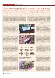
4.2- CONCEPT<br />
The process concept is based on the construction <strong>of</strong> a waterpro<strong>of</strong> secant<br />
pile diaphragm wall inside the body <strong>of</strong> the dam, 70cm far from the upstream face.<br />
The diaphragm was performed from the dam crest without any interference with<br />
the reservoir water, need <strong>of</strong> water level drop or intake obstruction. The secant<br />
bores were performed in sequence by drilling equipment with the use <strong>of</strong> a special<br />
guiding template. A drilling sequence composes an up to 2.60m long panel. The<br />
minimum acceptable thickness <strong>of</strong> the diaphragm panels was 2”.<br />
The minimum thickness was mechanically tested and recorded by a VHS<br />
underwater system. After the completion <strong>of</strong> a drilled panel, it was filled by mortar<br />
using “tremie” system. After the mortar filling <strong>of</strong> a panel, the last bore <strong>of</strong> the filled<br />
panel is drilled again and this bore starts the next sequence (see Figure 11).<br />
During the drilling process the panels are always filled with water in order to<br />
provide equal pressures between the panel and the reservoir.<br />
Figure 11- Drilling sequence<br />
Image 11- Séquence de perforation<br />
Diaphragm drilling direction<br />
Diaphragm drilling sequence
9<br />
Figure 12- Transversal section with diaphragm insertion<br />
Image 12- Section transversale avec insertion de mur diaphragme<br />
4.3- FIRST EVALUATION<br />
Before the beginning <strong>of</strong> the diaphragm wall rehabilitation works, several<br />
additional tests, analyses, and stability calculations were performed. The scope<br />
included permeability, capillarity, compression and shearing tests at samples <strong>of</strong><br />
the pilot drive <strong>of</strong> the diaphragm drive built in 1993, collected with rotary drilling<br />
probe extractors. Shearing tests at samples extracted from the contact between<br />
the diaphragm mortar and the concrete <strong>of</strong> the dam were also performed, in order<br />
to check the adherence between these different materials.<br />
Additional stability analysis were made considering the extreme hypothesis<br />
<strong>of</strong> break <strong>of</strong> the small dam´s body part between the diaphragm and the upstream<br />
face. These calculations were made attending to a CAESB concern about the<br />
aggressive soluble effects <strong>of</strong> the s<strong>of</strong>t water <strong>of</strong> the reservoir, with very low solid<br />
suspensions, on the upper part <strong>of</strong> the dam that would be in contact with the<br />
water.<br />
That concern was also dissipated by the evidence that even being in<br />
contact with the water, that part has the reactive effects severely decreased after<br />
diaphragm insert as a consequence <strong>of</strong> the end <strong>of</strong> the reaction renovation and<br />
leaching. Laboratory tests have also been made with the mortar mixture indicated<br />
by the project designers and performance tests simulating the underwater mortar<br />
application conditions, in order to verify the possibility <strong>of</strong> segregation.<br />
5- PERFORMANCE AND LOGISTICS<br />
The works were performed by two main groups <strong>of</strong> activities, drilling teams<br />
and mortar underwater application team:
10<br />
5.1- DRILLING<br />
The drilling activities were performed with drilling equipments using DTH<br />
(down the hole) hammers, guided by a special alignment template developed for<br />
this project. The drilling machinery had to be adapted specifically for the project<br />
in order to have the drilling equipment tower aligned at the diaphragm axis.<br />
Figure 13- Drilling machine during<br />
operation<br />
Figure 14- Alignment template used<br />
for drilling control<br />
Image 13- Perforatrice en opération Image 14- Gabarit d’alignement<br />
utilisé pour contrôler la perforation<br />
Figure 15- Alternated drilling panels<br />
for the diaphragm<br />
Image 15- Panneaux alternés de<br />
perforation pour le diaphragme<br />
Figure 16- Inspecting the diaphragm<br />
panel with TV camera<br />
Image 16- Inspection du panneau du<br />
diaphragme avec une caméra de<br />
télévision
11<br />
Figure 17- Discharging the mortar<br />
from the truck mixer to the<br />
placement pump<br />
Image 17- Décharge du mortier de la<br />
bétonnière dans la pompe de<br />
placement<br />
Figure 18- Filling the drilled<br />
diaphragm panel with mortar by a<br />
“tremie” pipe<br />
Image 18- Remplissage du panneau<br />
perforé du diaphragme avec le<br />
mortier par un tuyau trémie<br />
The project included 70,000 meters <strong>of</strong> 6” and 6 ½” drilled bores in 18<br />
months <strong>of</strong> work in two shifts. Midsize drilling equipments were used in the project<br />
(with weight between 6 and 11ton). At the peak <strong>of</strong> production the job site had five<br />
drilling machines working at the same time, four at the dam crest and one at the<br />
spillway top. The deepest hole reached 38 m depth, at block “I”, and 22 meters<br />
was the average drilling depth <strong>of</strong> the project.<br />
Boring deviations caused by flexion were minimized by the use <strong>of</strong> 4” masts.<br />
Several types <strong>of</strong> bits were tested at this project, the concave and drop center<br />
types had to be remarked for their best performance and alignment. The guiding<br />
template was built machining heavy hot rolling steel pipe. The drilling sequence<br />
illustrated above at Figure 11 consists in drilling a panel first bore that works as a<br />
guide for the next using the template. Moreover than guidance, the template is<br />
necessary to avoid bores overlay.<br />
5.2- MORTAR PLACEMENT<br />
The mortar filling was made underwater with “tremie” type tube. The work<br />
was done from the dam crest. The “tremie” pipe was connected directly to the<br />
mortar pumping line. The mortar pumping was made from pumps positioned<br />
beside the drum mixer parking area at the abutments outside border. In<br />
occasions when the pumping distance was longer than 100 meters, two serial<br />
disposed pumps were used.<br />
Two operational problems had to be solved:<br />
• The total mortar volume applied at the project was not enough to assure<br />
the viability <strong>of</strong> the installation <strong>of</strong> a mixing plant at the job site;<br />
• The distance from the job site to the nearest local concrete mixing plant<br />
(approximately 60 Km) was too long, consuming more than 50% <strong>of</strong> the mortar<br />
lifetime in the journey.
12<br />
These problems were solved by the construction <strong>of</strong> a cement storage place<br />
and a dosage ramp. With these very simple devices, the dosage <strong>of</strong> cement and<br />
admixtures could be made at the job site into drum mixers loaded with the<br />
specified amount <strong>of</strong> sand and water. This procedure <strong>of</strong> dosage at the job site<br />
ended the mortar lifetime problems and enhanced the quality control.<br />
6.1- WATER QUALITY CONTROL<br />
6- QUALITY CONTROL<br />
The water supply for Brasília City, by the <strong>Rio</strong> <strong>Descoberto</strong> Reservoir system<br />
is made from an inlet at the “H” block upstream face. The water is pumped<br />
through a 48” welded steel sewer straight for a Water Treatment Plant<br />
approximately 5 Km farther. At the Water Treatment Plant inlet the turbidity,<br />
coloration and colliform rates at the water are continuously controlled. Those<br />
indexes were kept stable during the works. Samples <strong>of</strong> the reservoir water had<br />
also been collected during the project performance and analyzed, including the<br />
determination <strong>of</strong> solid particles in suspension rate. This rate was, in fact, very<br />
low, as it is normal in high altitudes. These analyses showed that the quality <strong>of</strong><br />
the water was not affected by the construction works.<br />
6.2- PROCESS CONTROL<br />
6.2.1- Water Losses Flow Control<br />
Since the beginning <strong>of</strong> the works, the downstream face and inspection<br />
gallery water loss flows were controlled. At the downstream face small wooden<br />
channels where installed, discharging in a collect point.<br />
Figure 19- Water seepage control during the remedial works<br />
Image 19- Contrôle de l’infiltration de l’eau pendant les travaux de<br />
réparation
13<br />
At the inspection tunnel the flow measurement was made straight into the<br />
upstream pressure relief drains. The measurement was made by graduated<br />
containers and chronometers. During the job, the flow was strongly decreased<br />
(99%).<br />
6.2.2- Diaphragm Continuity<br />
The continuity <strong>of</strong> the diaphragm panels was controlled by mechanical<br />
testing and underwater VHS video system. The mechanical test was made by<br />
letting down a steel plate with the minimum diaphragm thickness allowed (see<br />
Figure 14). This steel plate was suspended by two ropes, and this procedure was<br />
hand made in order to assure the necessary sensitivity. In case <strong>of</strong> any kind <strong>of</strong><br />
obstruction or discontinuity, the plate wouldn’t reach the bottom <strong>of</strong> the diaphragm<br />
panel. In case <strong>of</strong> persistence <strong>of</strong> doubt after the mechanical test, the VHS<br />
underwater camera was used to inspect the suspect drive (see Figure16). This<br />
video system was also used to check and register the contact between different<br />
drives.<br />
6.2.3- Mortar Control<br />
Besides the initial analyses made before starting the works, during the<br />
project all the mortar applied was controlled and tested. The controls were made<br />
by casting 10 cylindrical specimens at each truck mixer (6m3 capacity). From<br />
those ten specimens, four <strong>of</strong> them were experimented at compressive tests at 4-<br />
days age, four were tested at 28-days age and the two remaining were kept<br />
tagged with all the data concerning the mortar recorded. The average<br />
compressive strength was 27 MPa; 3-days, 7-days, 28-days and 63-days age<br />
testing series have also been made.<br />
Figures 20- Control <strong>of</strong> the mortar used<br />
Images 20- Contrôle du mortier utilisé
14<br />
6.2.4- Mortar Drilled Cores Tests<br />
Cores were drilled from the mortar placed in the diaphragm and tested. The<br />
following statistical data were obtained:<br />
Property<br />
Mortar<br />
(diaphragm)<br />
Interface<br />
Concrete<br />
(dam)-<br />
Mortar<br />
(diaphragm)<br />
Concrete<br />
(dam)<br />
Absorption (%) 1.22<br />
Specific Weight (t/m3) 1.97 – 2.08 2.52<br />
Permeability (m/s) 10 -11 – 10 -10<br />
Compressive Strength (MPa) 12.7 – 31.1 25.7<br />
Splitting Tensile Strength (MPa) 1.87 1.14 4.51<br />
Direct Tensile Strength (MPa) 1.07 – 1.80 2.32<br />
Shear Strength (MPa) under Normal<br />
Pressure: 2.0 MPa<br />
Shear Strength (MPa) under Normal<br />
Pressure: 4.0 MPa<br />
Shear Strength (MPa) under Normal<br />
Pressure: 6.0 MPa<br />
Figure 21- Statistical data from drilled cores<br />
Image 21- Données statistiques des noyaux perforés<br />
2.77 – 5.57 2.05 – 3.77 5.03 – 5.14<br />
3.92 – 6.63 3.10 – 3.66 6.43 – 6.76<br />
5.57 – 8.38 4.50 – 6.10 12.42<br />
Figure 21- Drilled cores from<br />
diaphragm mortar<br />
Image 21- Noyaux perforés du<br />
mortier du diaphragme<br />
Figure 22- Drilled cores from<br />
diaphragm mortar, interface, and<br />
from the old concrete from the dam<br />
Image 22- Noyaux perforés du<br />
mortier du diaphragme, contact<br />
entre couches et du vieux béton du<br />
barrage<br />
7- CONSTRUCTION CHRONOLOGY<br />
The drilling works started in September <strong>of</strong> 2000 at the block “Q”, this was<br />
the first block finished in January 2001. The average drilling rate was 5000 meter<br />
per month, and the peak drilling month rate was reached in June 2001 with 8000<br />
meters drilled in 30 days, working with five drilling equipments.
15<br />
Figure 23- Construction chronology<br />
Image 23- Chronologie de la construction<br />
Figure 24- <strong>Rio</strong> <strong>Descoberto</strong> <strong>Dam</strong> and Reservoir during the rehabilitation<br />
works<br />
Image 24- Barrage du <strong>Rio</strong> <strong>Descoberto</strong> et Réservoir pendant les travaux de<br />
réhabilitation<br />
8- COMMENTS AND CONCLUSIONS<br />
The methodology adopted for the <strong>Rio</strong> <strong>Descoberto</strong> concrete dam<br />
rehabilitation was successful to reach the following purposes:<br />
<br />
<br />
<br />
<br />
Less expensive <strong>of</strong>fer;<br />
Guarantee the water supply in terms <strong>of</strong> quantity (no interruption) and<br />
quality;<br />
Reduce the water leakage to a normal level;<br />
Rehabilitate the dam structural safety<br />
Since the <strong>Rio</strong> <strong>Descoberto</strong> <strong>Dam</strong> rehabilitation start-up, the water losses have<br />
been measured and at the blocks completed until January 2002 (all <strong>of</strong> them with<br />
exception <strong>of</strong> the “I” block), the loss flow has decreased from 34 l/s to 0,3 l/s. The<br />
last block under rehabilitation work in 2002 January, the “I” block, had the flow<br />
reduced from 15 l/s to 2,0 l/s with only 80% <strong>of</strong> this block diaphragm wall<br />
completed at that time. The first blocks completed in January and February
16<br />
2000, the “Q” and “C” blocks, had no maintenance since then and remained with<br />
the same initial efficiency.<br />
The method attended to all the technical requests presented by the Owner,<br />
CAESB, preserving the reservoir’s water quality and keeping the CAESB<br />
capability <strong>of</strong> water supply along the course <strong>of</strong> the works, without any kind <strong>of</strong><br />
problems or disturbance for the Brazil’s Capital inhabitants.<br />
ACKNOWLEDGEMENT<br />
The contributions and recommendations from Pr<strong>of</strong>. Dr. Victor F.B. de Mello<br />
are greatly acknowledged<br />
REFERENCES<br />
[01] – PETRUCCI, ELADIO ENG.;BASÍLIO, FRANCISCO ASSIS PROF.- “Estudo da<br />
influência da Pirita nos agregados calcareos para a Barragem do <strong>Rio</strong><br />
<strong>Descoberto</strong>”, Geotécnica , Brasília, 12/1972,CAESB.<br />
[02]- GUERREIRO, M., FERNANDEZ CUEVAS, R., GUERREIRO, MA.J., GOMEZ LAA, G.-<br />
“Causes <strong>of</strong> failure <strong>of</strong> the Fonsagrada <strong>Dam</strong>”- ICOLD- XVII <strong>Congress</strong> on <strong>Large</strong><br />
<strong>Dam</strong>s- Vienna (1991)- pp. 49- 63;<br />
[03]- MELLO, VICTOR F.B. PROF. DR. PHD., ANDRIOLO, FRANCISCO RODRIGUES<br />
ENG., PACELLI, WALTON ENG- “Visits and Technical Recommendations for<br />
the <strong>Rio</strong> <strong>Descoberto</strong> <strong>Dam</strong>”,-, Brasília, Brazil, April & June/1993,CAESB;<br />
[04]- SIGOLO, PROF. DR.; ASSUMÇÃO, J.C.B, GEOLOGIST - “Relatório referente a<br />
análise de sedimentos G (Galeria) e R (Reservatório) visando<br />
caracterização mineral”- São Paulo, 06/1993, CAESB;<br />
[05]- SIGOLO, PROF. DR.; ASSUMÇÃO, J.C.B, GEOLOGIST- “Análise de amostras<br />
da Barragem do <strong>Rio</strong> <strong>Descoberto</strong>”, São Paulo, 02/1995, CAESB<br />
[06]- LEA, FREDERICK, M.- “The Chemistry <strong>of</strong> Cement and Concrete”- 3 rd<br />
Edition- Edward Arnold Publishers Ltd- Great Britain- 1970, pp.568-569<br />
[07]- “Exposure <strong>of</strong> <strong>Dam</strong> Concrete to Special Aggressive Waters” – ICOLD<br />
Bulletin 71- 1989- pp 19- 33;<br />
[08]- “Durability <strong>of</strong> Concrete Construction”- American Concrete Institute- pp.<br />
81- 85;<br />
[09]- CÁNOVAS, MANUEL FERNÁNDEZ- “Patologia e Terapia do Concreto<br />
Armado”- Editora Pini- São Paulo- Brazil- 1988- pp.37- 245;<br />
[10]- NEVILLE, A. M.- “Properties <strong>of</strong> Concrete”- 2 nd Edition- Halsted Press- John<br />
Wiley & Sons Inc. New York- 1973. pp.- 134- 137;<br />
[11]- “Recuperação da Barragem do <strong>Rio</strong> <strong>Descoberto</strong>- Histórico Sucinto- No.<br />
2”- CAESB- 01/1999;
17<br />
[12]- MELLO, VICTOR F.B. PROF. DR. PHD., ANDRIOLO, FRANCISCO RODRIGUES<br />
ENG., PACELLI, WALTON ENG- “Visits and Technical Recommendations for<br />
the <strong>Rio</strong> <strong>Descoberto</strong> <strong>Dam</strong>”,-, Brasília, Brazil, December/1999,CAESB;<br />
[13]- PACELLI, WALTON , ENG.; BITTENCOURT, RUBENS M.,ENG., ALBUQUERQUEM<br />
ALBÉRIA CAVALCANTI, ENG. MSC- “Ensaios com Testemunhos de Argamassa<br />
e Concreto”, Laboratório de Furnas 06/2001, CAESB.<br />
SUMMARY<br />
The <strong>Rio</strong> <strong>Descoberto</strong> <strong>Dam</strong>, owned by CAESB - Companhia de Saneamento<br />
do Distrito Federal - Brazil, is used as a reservoir for water supply to Brasilia City<br />
- Capital <strong>of</strong> Brazil.<br />
The dam, mass concrete gravity type, was finished in 1974. Some leaching<br />
water started to be observed at the downstream face since few years after the<br />
end <strong>of</strong> the construction, and filling <strong>of</strong> the reservoir.<br />
Some remedial works were adopted in different periods, as grouting and<br />
drainage systems, with no remarkable success. After these remedial works,<br />
CAESB have adopted a new approach looking for the origin <strong>of</strong> the problems, to<br />
adopt a definitive solution. After several analyses, the problem origin diagnosis<br />
was the presence <strong>of</strong> pyrite in the concrete aggregate combined with the acidic<br />
water action.<br />
A diaphragm wall was adopted as the rehabilitation methodology. This “ In<br />
the wet” technique, permitted the water supply for Brasilia (1.2 million people) not<br />
to be interrupted or affected in the course <strong>of</strong> the rehabilitation works. The<br />
reservoir’s water quality was continuously controlled during the process, and kept<br />
at the same level. The adopted methodology is described in this paper.<br />
RÉSUMÉ<br />
Le Barrage du <strong>Rio</strong> <strong>Descoberto</strong>, propriété de CAESB - Companhia de<br />
Saneamento do Distrito Federal - Brésil, est utilisé comme un réservoir de<br />
approvisionnement d’eau pour la ville de Brasilia – Capitale du Brésil.<br />
Le barrage, type barrage-poids en béton de masse, a été terminé en 1974.<br />
De l’eau de lessivage a été observée sur le parement aval depuis quelques<br />
années après la fin de la construction et remplissage du réservoir.<br />
Quelques travaux de réparation ont été adoptés dans différentes périodes,<br />
comme injection et systèmes de drainage, sans un succès expressif. Après ces<br />
travaux de réparation, CAESB a adopté un nouveau approche en cherchant<br />
l’origine des problèmes, pour adopter une solution en définitive. Après plusieurs<br />
analyses, le diagnostic du problème était la présence de pyrite dans le granulat<br />
de béton combiné avec l’action acide de l’eau.<br />
Un mur diaphragme a été adopté comme la méthodologie de réhabilitation.<br />
Cette technique “à mouillé” a permis l’approvisionnement d’eau pour Brasilia (1.2<br />
millions de personnes) de ne pas être interrompu ou affecté au cours des travaux<br />
de réhabilitation. La qualité de l’eau du réservoir a été continuellement contrôlée
18<br />
durant le procès et a été maintenue au même niveau. La méthodologie adoptée<br />
est décrite dans ce travail.