

Manual XBC-U
Manual XBC-U
Manual XBC-U

You also want an ePaper? Increase the reach of your titles
YUMPU automatically turns print PDFs into web optimized ePapers that Google loves.
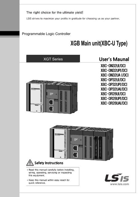
Programmable Logic Controller<br />
XGB Main unit(<strong>XBC</strong>-U Type)<br />
XGT Series<br />
<strong>XBC</strong>-DN32U(/DC)<br />
<strong>XBC</strong>-DN32UP(/DC)<br />
<strong>XBC</strong>-DN32UA (/DC)<br />
<strong>XBC</strong>-DP32U(/DC)<br />
<strong>XBC</strong>-DP32UP(/DC)<br />
<strong>XBC</strong>-DP32UA(/DC)<br />
<strong>XBC</strong>-DR28U(/DC)<br />
<strong>XBC</strong>-DR28UP(/DC)<br />
<strong>XBC</strong>-DR28UA(/DC)
Revision History<br />
Version Date Remark Part Page<br />
V 1.0 2015.5 1. First Edition - -<br />
V1.1 2015.7<br />
1.source output PLC added(<strong>XBC</strong>-DPxxU(A)(P))<br />
2.DC power PLC added(/DC)<br />
3.PID bumpless added<br />
-_PID_MV_BMPL flag comment modified<br />
4.Web server download modified<br />
-2) communication setup<br />
-3.5 Improvement of the web server’s speed<br />
5.Internal Input/output circuit & TB modified<br />
6.deviec&flag modified<br />
(1) web server flag added<br />
(2) Timer flag added<br />
(3) N Device Notice modified(cannot write)<br />
0<br />
2<br />
0<br />
1<br />
2<br />
5<br />
5<br />
2<br />
5<br />
App<br />
App<br />
Front<br />
2-1~4,3-6<br />
Front<br />
3-5<br />
-<br />
6-20<br />
-<br />
3-20~21<br />
3-69~71<br />
3-5~7<br />
3-11<br />
App 1-2<br />
App 1-10<br />
※ The number of User’s manual is indicated the right side of the back cover.<br />
c LSIS Co.,Ltd. 2010 All Rights Reserved.
Safety Instruction<br />
Before using the product …<br />
For your safety and effective operation, please read the safety instructions<br />
thoroughly before using the product.<br />
► Safety Instructions should always be observed in order to prevent accident<br />
or risk with the safe and proper use the product.<br />
► Instructions are separated into “Warning” and “Caution”, and the meaning of<br />
the terms is as follows;<br />
Warning<br />
Indicates a potentially hazardous situation which,<br />
if not avoided, could result in death or serious injury<br />
Caution<br />
Indicates a potentially hazardous situation which,if<br />
not avoided, may result in minor or moderate injury.<br />
It may also be used to alert against unsafe practices<br />
► The marks displayed on the product and in the user’s manual have the<br />
following meanings.<br />
Be careful! Danger may be expected.<br />
Be careful! Electric shock may occur.<br />
► The user’s manual even after read shall be kept available and accessible to<br />
any user of the product.
Safety Instruction<br />
Safety Instructions when designing<br />
Warning<br />
Please, install protection circuit on the exterior of PLC to protect<br />
the whole control system from any error in external power or PLC<br />
module. Any abnormal output or operation may cause serious problem<br />
in safety of the whole system.<br />
- Install applicable protection unit on the exterior of PLC to protect<br />
the system from physical damage such as emergent stop switch,<br />
protection circuit, the upper/lowest limit switch, forward/reverse<br />
operation interlock circuit, etc.<br />
- If any system error (watch-dog timer error, module installation error,<br />
etc.) is detected during CPU operation in PLC, the whole output is<br />
designed to be turned off and stopped for system safety. However,<br />
in case CPU error if caused on output device itself such as relay or<br />
TR can not be detected, the output may be kept on, which may<br />
cause serious problems. Thus, you are recommended to install an<br />
addition circuit to monitor the output status.<br />
Never connect the overload than rated to the output module nor<br />
allow the output circuit to have a short circuit, which may cause a<br />
fire.<br />
Never let the external power of the output circuit be designed to<br />
be On earlier than PLC power, which may cause abnormal output or<br />
operation.<br />
In case of data exchange between computer or other external<br />
equipment and PLC through communication or any operation of<br />
PLC (e.g. operation mode change), please install interlock in the<br />
sequence program to protect the system from any error. If not, it<br />
may cause abnormal output or operation.
Safety Instruction<br />
Safety Instructions when designing<br />
Caution<br />
I/O signal or communication line shall be wired at least 100mm<br />
away from a high-voltage cable or power line. If not, it may cause<br />
abnormal output or operation.<br />
Safety Instructions when designing<br />
Caution<br />
Use PLC only in the environment specified in PLC manual or<br />
general standard of data sheet. If not, electric shock, fire, abnormal<br />
operation of the product or flames may be caused.<br />
Before installing the module, be sure PLC power is off. If not,<br />
electric shock or damage on the product may be caused.<br />
Be sure that each module of PLC is correctly secured. If the<br />
product is installed loosely or incorrectly, abnormal operation, error or<br />
dropping may be caused.<br />
Be sure that I/O or extension connecter is correctly secured. If<br />
not, electric shock, fire or abnormal operation may be caused.<br />
If lots of vibration is expected in the installation environment,<br />
don’t let PLC directly vibrated. Electric shock, fire or abnormal<br />
operation may be caused.<br />
Don’t let any metallic foreign materials inside the product, which<br />
may cause electric shock, fire or abnormal operation..
Safety Instruction<br />
Safety Instructions when wiring<br />
Warning<br />
Prior to wiring, be sure that power of PLC and external power is<br />
turned off. If not, electric shock or damage on the product may be<br />
caused.<br />
Before PLC system is powered on, be sure that all the covers of<br />
the terminal are securely closed. If not, electric shock may be caused<br />
Caution<br />
Let the wiring installed correctly after checking the voltage rated<br />
of each product and the arrangement of terminals. If not, fire,<br />
electric shock or abnormal operation may be caused.<br />
Secure the screws of terminals tightly with specified torque when<br />
wiring. If the screws of terminals get loose, short circuit, fire or abnormal<br />
operation may be caused.<br />
*<br />
Surely use the ground wire of Class 3 for FG terminals, which is<br />
exclusively used for PLC. If the terminals not grounded correctly,<br />
abnormal operation may be caused.<br />
Don’t let any foreign materials such as wiring waste inside the<br />
module while wiring, which may cause fire, damage on the product<br />
or abnormal operation.
Safety Instruction<br />
Safety Instructions for test-operation or repair<br />
Warning<br />
Don’t touch the terminal when powered. Electric shock or abnormal<br />
operation may occur.<br />
Prior to cleaning or tightening the terminal screws, let all the<br />
external power off including PLC power. If not, electric shock or<br />
abnormal operation may occur.<br />
Don’t let the battery recharged, disassembled, heated, short or<br />
soldered. Heat, explosion or ignition may cause injuries or fire.<br />
Caution<br />
Don’t remove PCB from the module case nor remodel the module.<br />
Fire, electric shock or abnormal operation may occur.<br />
Prior to installing or disassembling the module, let all the external<br />
power off including PLC power. If not, electric shock or abnormal<br />
operation may occur.<br />
Keep any wireless installations or cell phone at least 30cm away<br />
from PLC. If not, abnormal operation may be caused.<br />
Safety Instructions for waste disposal<br />
Caution<br />
Product or battery waste shall be processed as industrial waste.<br />
The waste may discharge toxic materials or explode itself.
About User’s <strong>Manual</strong><br />
About User’s <strong>Manual</strong><br />
Congratulations on purchasing PLC of LSIS Co.,Ltd.<br />
Before use, make sure to carefully read and understand the User’s <strong>Manual</strong> about the functions,<br />
performances, installation and programming of the product you purchased in order for correct use and<br />
importantly, let the end user and maintenance administrator to be provided with the User’s <strong>Manual</strong>.<br />
The Use’s <strong>Manual</strong> describes the product. If necessary, you may refer to the following description and order<br />
accordingly. In addition, you may connect our website(http://www.lsis.com/) and download the information as<br />
a PDF file.<br />
Relevant User’s <strong>Manual</strong><br />
Title<br />
XG5000 User’s<br />
<strong>Manual</strong><br />
XGK/XGB Series<br />
Instruction &<br />
Programming<br />
<strong>XBC</strong><br />
Ultimate Performance<br />
XGB Unit<br />
XGB Analog<br />
User’s <strong>Manual</strong><br />
XGB Position<br />
User’s <strong>Manual</strong><br />
XGB Cnet I/F<br />
User’s <strong>Manual</strong><br />
XGB Fast Ethernet I/F<br />
User’s <strong>Manual</strong><br />
CANopen<br />
Commnunication<br />
Module<br />
EtherNet/IP<br />
Commnunication<br />
Module<br />
XGB Profibus-DP I/F<br />
(Master) User’ s<br />
Manaual<br />
XGB Profibus-DP I/F<br />
(Slave) User’ s<br />
Manaual<br />
XGB DeviceNet I/F<br />
(Slave) User’ s<br />
Manaual<br />
XGB High speed<br />
counter module User’s<br />
<strong>Manual</strong><br />
Description<br />
It describes how to use XG5000 software especially about<br />
online functions such as programming, printing, monitoring<br />
and debugging by using XGT series products.<br />
No. of User<br />
<strong>Manual</strong><br />
10310000512<br />
It describes how to use the instructions for programming<br />
using XGK/XGB series. 10310000510<br />
It describes how to use XGB main unit, system configuration,<br />
mechanism ,program function ,input/output function, Built-in<br />
High-speed Counter, Datalog, PID Control, Built-in<br />
Communication function, Built-in Position, Built-in Analog<br />
input/output..<br />
It describes how to use the specification of analog<br />
input/analog output/temperature input module, system<br />
configuration and built-in PID control for XGB main unit.<br />
It describes how to use built-in Position function for XGB<br />
main unit.<br />
It describes how to use built-in communication function for<br />
XGB main unit and external Cnet I/F module.<br />
10310001374<br />
10310000920<br />
10310000927<br />
10310000816<br />
It describes how to use XGB FEnet I/F module. 10310000873<br />
It describes how to use XGB CANopen Commnunication<br />
Module<br />
It describes how to use XGB EtherNet/IP Communication<br />
module<br />
It describes how to use XGB Profibus-DP I/F<br />
(Master) Commnunication Module<br />
It describes how to use XGB Profibus-DP I/F<br />
(Slave) Commnunication Module<br />
It describes how to use XGB DeviceNet I/F<br />
(Slave) Commnunication Module<br />
It describes how to use High speed counter(XBF-HO02A,<br />
XBF-HD02A)<br />
0310001245<br />
10310001159<br />
10310001310<br />
10310001410<br />
10310001414<br />
10310001240
◎ Contents ◎<br />
Part1. System<br />
Chapter 1 Introduction ..................................................................................................... 1-1~1-17<br />
1.1 Guide to Use This <strong>Manual</strong> ............................................................................................. 1-1<br />
1.2 Features ........................................................................................................................ 1-3<br />
1.3 Terminology ................................................................................................................... 1-5<br />
Chapter 2 System configuration ........................................................................................ 2-1~2-12<br />
2.1 Table of Products Configuration .................................................................................... 2-1<br />
2.2 Classification and Type of Product Name ..................................................................... 2-3<br />
2.3 High performance XGB’s System Configuration ........................................................... 2-7<br />
Chapter 3 Specifications ........................................................................................................ 3-1~3-9<br />
3.1 Names and Functions of Each Part .............................................................................. 3-1<br />
3.2 Power Specifications ..................................................................................................... 3-5<br />
3.3 Battery ........................................................................................................................... 3-5<br />
3.4 Performance specifications ........................................................................................... 3-7<br />
Chapter 4 Installation and wiring ........................................................................................... 4-1~3-9<br />
4.1 Parameter & Operation data ......................................................................................... 4-1<br />
4.2 Attachment/Detachment of Modules ............................................................................. 4-6<br />
4.3 Wire ............................................................................................................................. 4-14<br />
Chapter 5 Maintenance ......................................................................................................... 5-1~5-2<br />
5.1 Maintenance and Inspection ......................................................................................... 5-1<br />
5.2 Daily Inspection ............................................................................................................. 5-2<br />
5.3 Periodic Inspection ........................................................................................................ 5-2<br />
Chapter 6 Trouble Shooting ................................................................................................ 6-1~6-13<br />
6.1 Basic Procedure of Troubleshooting ............................................................................. 6-1<br />
6.2 Troubleshooting ............................................................................................................. 6-1<br />
6.3 Troubleshooting Questionnaire ..................................................................................... 6-7<br />
6.4 Troubleshooting Examples ............................................................................................ 6-6<br />
6.5 Error Code List ............................................................................................................ 6-12<br />
Chapter 7 EMC Standard ...................................................................................................... 7-1~7-4<br />
7.1 Requirements for Conformance to EMC Directive ........................................................ 7-1<br />
7.2 Requirement to Conform to the Low-voltage Directive ................................................. 7-4
Part2. Basic Functions<br />
Chapter 1 Program Configuration and Operation Method .................................................. 1-1~1-32<br />
1.1 Programming Basics ..................................................................................................... 1-1<br />
1.2 Operation mode........................................................................................................... 1-24<br />
1.3 Memory ....................................................................................................................... 1-27<br />
Chapter 2 CPU Function ..................................................................................................... 2-1~1-32<br />
2.1 Type Setting .................................................................................................................. 2-1<br />
2.2 Parameter Setting ......................................................................................................... 2-2<br />
2.3 Self-Diagnosis Function ............................................................................................. 2-5<br />
2.4 RTC Function .............................................................................................................. 2-13<br />
2.5 Timer counter function ................................................................................................. 2-15<br />
2.6 Remote Functions ....................................................................................................... 2-21<br />
2.7 I/O forced On/Off Functions ........................................................................................ 2-22<br />
2.8 Direct I/O Operation Function ..................................................................................... 2-23<br />
2.9 Function saving the operation history ......................................................................... 2-23<br />
2.10 How to allocate I/O No. ............................................................................................. 2-25<br />
2.11 Program Modification during operation (Modification during RUN) ......................... 2-26<br />
2.12 Read I/O information. ................................................................................................ 2-29<br />
2.13 How to allocate I/O No. ............................................................................................. 2-30<br />
2.14 PLC’s Read-Protect Function ....................................................................................2-36<br />
2.15 Function to delete all of the PLC. ............................................................................ 2-37<br />
Chapter 3 Input/Output Specifications ................................................................................. 3-1~3-25<br />
3.1 Introduction .................................................................................................................... 3-1<br />
3.2 Main Unit Digital Input Specifications ............................................................................ 3-8<br />
3.3 Main Unit Digital Output Specifications ....................................................................... 3-9<br />
3.4 Digital Input Specifications .......................................................................................... 3-10<br />
3.5 Digital Output Specifications ....................................................................................... 3-13<br />
3.6 Combined Digital I/O module Input Specification ........................................................ 3-22<br />
3.7 Combined Digital I/O module Output Specification ..................................................... 3-23<br />
3.8 I/O modules’ Functions ................................................................................................ 3-24<br />
Chapter 4 Built-in High-speed Counter Function ................................................................ 4-1~4-29<br />
4.1High-speed Counter Specifications ................................................................................ 4-1<br />
4.2 Installation and Wiring ................................................................................................. 4-21<br />
4.3 Internal Memory ........................................................................................................ 4-22<br />
4.4 Example of Using High-speed Counter ....................................................................... 4-26
Chapter 5 Data Log Function ............................................................................................ 5-1~5-102<br />
5.1 Overview ....................................................................................................................... 5-1<br />
5.2 Performance Specifications ........................................................................................... 5-6<br />
5.3 Specific Functions ....................................................................................................... 5-7<br />
5.4 Regular Save ............................................................................................................... 5-27<br />
5.5 Trigger Save ................................................................................................................ 5-33<br />
5.6 Event Save .................................................................................................................. 5-54<br />
5.7 Additional Functions .................................................................................................... 5-76<br />
5.8 CSV File Structure ....................................................................................................... 5-83<br />
5.9 SD Memory Card......................................................................................................... 5-85<br />
5.10 Flag List ..................................................................................................................... 5-91<br />
5.11 Data Processing Time ............................................................................................... 5-95<br />
Chapter 6 Built-in PID Function ........................................................................................... 6-1~6-49<br />
6.1 Features of Built-in PID Function .................................................................................. 6-1<br />
6.2 Basic Theory of PID Control .......................................................................................... 6-2<br />
6.3 Functional Specifications of PID Control ..................................................................... 6-9<br />
6.4 Usage of PID Control Functions .................................................................................. 6-10<br />
6.5 PID Instructions ........................................................................................................... 6-26<br />
6.6 PID Auto-tuning ........................................................................................................... 6-28<br />
6.7 Example Programs ...................................................................................................... 6-37<br />
6.8 Error / Warning Codes ................................................................................................. 6-48<br />
Part3. Embedded Positioning<br />
Chapter 1 Overview ............................................................................................................. 1-1~1-12<br />
1.1 Characteristics .................................................................................................................. 1-1<br />
1.2 Purpose of Positioning Control ...................................................................................... 1-3<br />
1.3 Signal Flow of Embedded Positioning ........................................................................ 1-4<br />
1.4 Function overview of embedded positioning ................................................................. 1-5<br />
Chapter 2 Specifications ...................................................................................................... 2-1~2-12<br />
2.1 Characteristics .................................................................................................................. 2-1<br />
2.2 External Interface I/O Specifications ............................................................................. 2-3<br />
2.3 The Name of Each Part ............................................................................................... 2-8<br />
Chapter 3 Operation Order and Installation ........................................................................ 3-1~3-20
3.1 Operation Order ................................................................................................................ 3-1<br />
3.2 Installation ..................................................................................................................... 3-2<br />
3.3 Notices in Wiring ....................................................................................................... 3-20<br />
Chapter 4 Positioning Parameter & Operation Data ........................................................... 4-1~4-33<br />
4.1 Parameter & Operation data .............................................................................................. 4-1<br />
4.2 Basic Parameter ............................................................................................................ 4-2<br />
4.3 Extended Parameter ................................................................................................... 4-7<br />
4.4 <strong>Manual</strong> Operation Parameter ...................................................................................... 4-19<br />
4.5 Homing Parameter .................................................................................................... 4-20<br />
4.6 I/O Signal Parameter ................................................................................................. 4-24<br />
4.7 Common Parameter .................................................................................................. 4-25<br />
4.8 Operation Data .......................................................................................................... 4-29<br />
Chapter 5 Internal Memory and I/O Signal ...........................................................................5-1~5-11<br />
5.1 Internal Memory ................................................................................................................ 5-1<br />
5.2 I/O Signal ....................................................................................................................... 5-9<br />
Chapter 6 Command ........................................................................................................... 6-1~6-64<br />
6.1 General Command ............................................................................................................ 6-1<br />
6.2 Dedicated Commands ................................................................................................... 6-5<br />
6.3 Use of Dedicated Command ......................................................................................... 6-7<br />
Chapter 7 Program ............................................................................................................ 7-1~7-47<br />
7.1Example of Programming ................................................................................................... 7-1<br />
Chapter 8 Functions .......................................................................................................... 8-1~8-161<br />
8.1 Homing ............................................................................................................................ 8-1<br />
8.2 Positioning Control .......................................................................................................... 8-11<br />
8.3 <strong>Manual</strong> Operation Control .............................................................................................. 8-100<br />
8.4 Synchronous Control ..................................................................................................... 8-107<br />
8.5 Modification Function of Control ................................................................................... 8-126<br />
8.6 Auxiliary Function of Control ........................................................................................... 8-144<br />
8.7 Data Modification Function ............................................................................................. 8-150
Chapter 9 Positioning Error Information & Solutions........................................................... 9-1~9-15<br />
9.1 Positioning Error Information & Solutions ............................................................................ 9-1<br />
Chapter 10 Internal Memory Address of “Read/Write Variable Data” command ............ 10-1~10-92<br />
10.1 Parameter memory address ........................................................................................... 10-1<br />
10.2 Axis 1 operation data memory address ............................................................................ 10-5<br />
10.3 Axis 2 operation data memory address .......................................................................... 10-14<br />
10.4 Axis 3 operation data memory address .......................................................................... 10-23<br />
10.5 Axis 4 operation data memory address .......................................................................... 10-32<br />
10.6 CAM data memory address .......................................................................................... 10-41<br />
10.7 User CAM data memory address .................................................................................. 10-91<br />
Part4. Embedded Analog<br />
Chapter 1. Embedded Analog Function .............................................................................. 1-1~1-58<br />
1.1 Setting Sequence before Operation .............................................................................. 1-1<br />
1.2 Name of Each Part and Functions ................................................................................ 1-4<br />
1.3 Characteristic of I/O Conversion ................................................................................... 1-5<br />
1.4 Accuracy ................................................................................................................... 1-10<br />
1.5 Embedded Functions ................................................................................................ 1-12<br />
1.6 Wiring ........................................................................................................................ 1-23<br />
1.7 Operation Parameter Setting ......................................................................................... 1-27<br />
1.8 Special Module Monitoring Functions.............................................................................. 1-30<br />
1.9 Register U Devices ....................................................................................................... 1-35<br />
1.10 Configuration and Function of Internal Memory .............................................................. 1-41<br />
1.11 Example Program ....................................................................................................... 1-54<br />
1.12 Troubleshooting .......................................................................................................... 1-56
Part 5 Built-in communication functions<br />
Chapter.1 Built-in FEnet communication ........................................................................... 1-1~1-120<br />
1.1 Outline ........................................................................................................................... 1-1<br />
1.2 Specifications ................................................................................................................ 1-3<br />
1.3 Specifications of installation and a trial run ................................................................... 1-9<br />
1.4 Configuration of FEnet communication system .......................................................... 1-13<br />
1.5 Protocols for each service ........................................................................................... 1-15<br />
1.6 Dedicated services ...................................................................................................... 1-32<br />
1.7 P2P service .................................................................................................................... 1-39<br />
1.8 High speed link ............................................................................................................... 1-68<br />
1.9 Remote communication ................................................................................................... 1-80<br />
1.10 File Transfer Protocol (FTP) ........................................................................................... 1-84<br />
1.11 E-mail Transfer(SMTP) ................................................................................................ 1-102<br />
1.12 Time synchronization(SNTP) ........................................................................................ 1-117<br />
1.13 Troubleshooting .......................................................................................................... 1-119<br />
Chapter 2 Built-in Cnet Communication ............................................................................ 2-1~2-128<br />
2.1 General .......................................................................................................................... 2-1<br />
2.2 Specification .................................................................................................................. 2-2<br />
2.3 Cnet Communication System Configuration ............................................................... 2-10<br />
2.4 Basic Setting for Communication ................................................................................ 2-18<br />
2.5 Server Function and P2P service ................................................................................ 2-26<br />
2.6 XGT Dedicated Protocol .................................................................................................. 2-50<br />
2.7 LS Bus Protocol .............................................................................................................. 2-70<br />
2.8 Modbus Protocol ............................................................................................................. 2-76<br />
2.9 Diagnosis Function ......................................................................................................... 2-92<br />
2.10 Example Program ....................................................................................................... 2-101<br />
2.11 Error Code .................................................................................................................. 2-127
Chapter 3 Web Server ......................................................................................................... 3-1~3-73<br />
3.1 Outline of the Web Server ............................................................................................. 3-1<br />
3.2 Specification .................................................................................................................. 3-4<br />
3.3 How to use the web server ............................................................................................ 3-7<br />
3.4 Functions of the web server ........................................................................................ 3-14<br />
3.5 Improvement of the web server’s speed ..................................................................... 3-69<br />
3.6Directions for use of the web server............................................................................. 3-72<br />
Part 6 Appendix<br />
Appendix 1 Flag list .......................................................................................................... App1-1~11<br />
Appendix 1.1 Special Relay (F) List ............................................................................ App 1-1<br />
Appendix 1.2 Communication Relay (L) List ............................................................... App 1-6<br />
Appendix 2 Dimension (Unit : mm) .................................................................................. App2-1~5<br />
Appendix 3 Instruction List ............................................................................................... App3-1~41<br />
Appendix 3.1 Classification of Instructions ................................................................. App 3-1<br />
Appendix 3.2 Basic Instructions .................................................................................. App 3-2<br />
Appendix 3.3 Data transfer instruction ........................................................................ App 3-5<br />
Appendix 3.4 Classification of Instructions ............................................................... App 3-38<br />
Appendix 4 How to make the user page .......................................................................... App4-1~56<br />
Appendix 4.1 Device monitoring parameter ................................................................ App 4-1<br />
Appendix 4.2 Individual exercise related to the user page ......................................... App 4-7<br />
Appendix 4.3 Integrated exercise for the user page : Temperature control system .. App 4-45
Chapter 1 Introduction<br />
System<br />
Part 1. System<br />
Chapter 1 Introduction<br />
1.1 Guide to this <strong>Manual</strong><br />
This manual includes specifications, functions and handling instructions for XGB series PLC. This manual is divided up into chapters as follows<br />
No. Title Contents<br />
Chapter 1<br />
Introduction<br />
Describes configuration of this manual, unit’s features and<br />
terminology.<br />
Chapter 2<br />
System Configurations<br />
Describes available units and system configuration in the XGB<br />
series.<br />
1.system<br />
Chapter 3 Specifications Describes general specifications of units used in the XGB series.<br />
Chapter 4 CPU Specifications Describes performances, specifications and operations.<br />
Chapter 5<br />
Maintenance<br />
Describes the check items and method for long-term normal<br />
operation of the PLC system.<br />
Chapter 6 Troubleshooting Describes various operation errors and corrective actions.<br />
Chapter 7 EMC Specifications Describes system configuration following EMC specification.<br />
Chapter 1<br />
Program Configuration and Operation<br />
Method<br />
Describes performances, specifications and operations.<br />
2.Main<br />
Chapter 2<br />
CPU Specifications<br />
Chapter 3 Input/Output Specifications Describes operation of basic and input/output.<br />
Chapter 4 Built-in High-speed Counter Function Describes built-in high-speed counter functions.<br />
Chapter 5 Datalog Function Describes Datalog Function<br />
1-1
System<br />
Chapter 1 Introduction<br />
Chapter 6 Built-in PID Function Describes Built-in PID Function<br />
Describes the specification, method to use each positioning<br />
Chapter 1<br />
Overview<br />
function, programming and the wiring with external equipment of<br />
embedded positioning function.<br />
Chapter 2 Specifications Describes general specifications of Positing function.<br />
3.Positioning<br />
Chapter 3<br />
Operation Order and Installation<br />
Describes the Operation order in case of positioning operation by<br />
embedded positioning.<br />
Describes parameter and operation data to be set by software<br />
Chapter 4<br />
Positioning Parameter & Operation Data<br />
package with embedded positioning.<br />
Describes the internal memory used for positioning module if<br />
Chapter 5<br />
Internal Memory and IO Signal<br />
XGB Main unit<br />
4.Analog<br />
Chapter 1 Embedded Analog Describes the Built-in Analog Function used in XGB PLC.<br />
5.Communication<br />
Chapter 1 Built-in FEnet Communication Describes the Built-in FEnet Communication used in XGB PLC.<br />
Chapter 2 Built-in Cnet Communication Describes the Built-in Cnet Communication used in XGB PLC.<br />
Appendix 1 Flag List Describes the types and contents of various flags.<br />
6.Appendix<br />
Appendix 2 Dimension Shows dimensions of the main units and expansion modules.<br />
Appendix 3 Instruction List Describes the special relay and instruction list.<br />
1-2
Chapter 1 Introduction<br />
System<br />
1.2 Features<br />
The high performance XGB basic unit has the following characteristics.<br />
1.2.1 Advanced Performances<br />
(1) Rapid Processing Speed<br />
The processing speed has been improved up to more than 30% compared to the existing XGB PLC.<br />
Items <strong>XBC</strong> ‘SU’ Type <strong>XBC</strong> ‘H' Type <strong>XBC</strong> ‘U’ Type Remarks<br />
Sequence<br />
command<br />
94 ns 84 ns 60 ns<br />
Based on<br />
MLOAD command<br />
Data command 2.1 μs 1.54 μs 1.58 μs Based on MOV command<br />
4.99 μs 4.85 μs 3.8 μs RADD command<br />
Real<br />
4.5 μs 4.64 μs 3.8 μs RMUL command<br />
Long Real<br />
8.5 μs 8.18 μs 5.9 μs LADD command<br />
8.0 μs 9.62 μs 6.0 μs LMUL command<br />
(2) Advanced embedded functions<br />
Various and special communication functions that the existing XGB could not provide are embedded.<br />
- Embedded Data logging function through the SD memory<br />
- Embedded Fast Ethernet supporting the switching function<br />
- Embedded 4-axis positioning function supporting CAM operation, multi-axis interpolation<br />
(<strong>XBC</strong>-DN32UP/ DP32UP/DR28UP)<br />
- Embedded analog I/O 8 channels with 14bit resolution (<strong>XBC</strong>-DN32UA/ <strong>XBC</strong>-DP32UA //DR28UA)<br />
1.2.2 Flexibility of System Configuration<br />
(1) The small and medium-sized system can be established, which controls up to 352 points I/O through 10-<br />
stage expansion.<br />
(2) Compact size<br />
Compared to the existing XGB basic unit, this product has various embedded functions to enhance<br />
functionality and has a reduced size so you can install it even in a small space. (Unit : mm)<br />
Type Model Size (W * H * D) Remarks<br />
<strong>XBC</strong>-DN32U/DP32U/DR28U 150 * 90 * 64<br />
Same size as to<br />
Basic unit<br />
<strong>XBC</strong>-DN32UP/DP32UP/DR28UP 185 * 90 * 64<br />
DC power PLC<br />
<strong>XBC</strong>-DN32UA/DP32UA/DR28UA 185 * 90 * 64<br />
Expansion module XBE-,XBF-,XBL- 20 * 90 * 60 Based on the minimum size<br />
(3) Securing compatibility of the existing expansion/special/communication module<br />
All types of the existing XGB expansion/special/communication modules are available.<br />
(4) Expanding the applications through various expansion modules<br />
- It provides 8 points, 16 points, 32 points module I/O expansion module (In the case of relay output, 8/16<br />
points module) with single input, single output, mixed I/O module.<br />
- It supports various special modules such as positioning, high-speed counter, analog I/O, temperature<br />
input, temperature control.<br />
- It provides various communication I/F modules such as Cnet, FEnet, RAPIEnet, CANOpen, Profibus-DP,<br />
DeviceNet.<br />
1-3
System<br />
Chapter 1 Introduction<br />
1.2.3 Powerful Embedded Functions<br />
(1) Embedded high-speed counter function<br />
- The high-speed counter with up to 100kpps 8 channels(based on 1 phase 1 input 1 multiplication) is<br />
embedded.<br />
- Various additional functions such as comparative readout, comparative task, frequency measurement,<br />
revolutions per hour, etc. are provided.<br />
- Parameter setting using XG5000, various monitoring and diagnosis functions are provided.<br />
- You can conduct a trial run through XG5000’s monitoring without the program so you can easily check of<br />
abnormalities of external wirings and data setting.<br />
(2) Embedded data log function<br />
- The data log function that can use the SD memory card of up to 16GB is embedded.<br />
- You can save various device data of the PLC for a long time with only parameter setting using XG5000.<br />
- You can save the desired data depending on different conditions such as trigger collection, event collection,<br />
etc.<br />
- It supports the remote data access through FTP communication.<br />
(3) Embedded communication function<br />
- It has embedded Cnet 2 channels and Enet 1 channel at the same time.<br />
- It can communicate with other devices very easily without the special communication I/F module by using the<br />
embedded communication function.<br />
- It enhances convenience by providing various protocols such as dedicated communication, customization,<br />
etc.<br />
-You can check the communication state very easily thanks to the diagnosis function and<br />
transmitting∙receiving frame monitoring function.<br />
- The 2 ports switch function embedded in Ethernet makes the configuration of line topology easier.<br />
(4) Embedded PID function<br />
- It supports the embedded PID control function up to 16 loops.<br />
- It provides parameter setting using XG5000, convenient loop state monitoring through trend monitor.<br />
- You can get the control constant easily by the improved automatic synchronization function.<br />
- You can improve control accuracy by using various additional functions such as PWM output, ∆MV, ∆PV,<br />
SV Ramp, etc.<br />
- It provides various control modes such as forward/reverse mixed operation, 2-stage SV PID control,<br />
cascade control, etc.<br />
-You can secure stability through various alarm functions such as PV MAX, PV change warning, etc.<br />
(5) Embedded position control function(Available for <strong>XBC</strong>-DN32UP/ DP32UP/DR28UP type only)<br />
- The line drive output positioning function with up to 2Mpps 4-axis is embedded.<br />
- It provides parameter setting using XG-PM that is the exclusive setting tool, operation data edition, diverse<br />
monitoring and diagnosis functions.<br />
- You can conduct a trial run through XG-PM’s monitoring without the program so you can easily check the<br />
external wirings and operation data.<br />
(6) Embedded analog I/O function(Available for <strong>XBC</strong>-DN32UA/DN32UA/DR28UA type only)<br />
- The analog input 4 channels(voltage/current), analog output 4channels(voltage 2 channels, current 2<br />
channels) are embedded.<br />
- It can measure the analog value more accurately thanks to the high resolution of 14bit.<br />
- You can conduct a trial run through XG5000’s monitoring without the program so you can easily check the<br />
external wirings and operation data.<br />
1-4
Chapter 1 Introduction<br />
System<br />
1.3 Terminology<br />
1.2.1 General term<br />
The following table gives definition of terms used in this manual.<br />
Terms Definition Remark<br />
Module<br />
Unit<br />
PLC System<br />
A standard element that has a specified function which configures the<br />
system. Devices such as I/O board, which inserted onto the mother board.<br />
A single module or group of modules that perform an independent operation<br />
as a part of PLC systems.<br />
A system which consists of the PLC and peripheral devices.<br />
A user program can control the system.<br />
Example)<br />
Expansion module,<br />
Specialmodule,<br />
Communication<br />
module<br />
Example)<br />
Main unit, Expansion<br />
unit<br />
-<br />
XG5000<br />
A program and debugging tool for the MASTER-K series.<br />
It executes program creation, edit, compile and debugging.<br />
(PADT: Programming Added Debugging Tool)<br />
-<br />
XG - PD<br />
Software to execute description, edition of basic parameter, high speed link,<br />
P2P parameter, and function of communication diagnosis -<br />
I/O image area Internal memory area of the CPU module which used to hold I/O status.<br />
Cnet Computer Network -<br />
FEnet Fast Ethernet Network -<br />
RAPInet RAPInet Network -<br />
CANopen Controller Area Network -<br />
Pnet Profibus-DP Network -<br />
Dnet DeviceNet Network -<br />
RTC<br />
Watchdog Timer<br />
Abbreviation of ‘Real Time Clock’. It is used to call general IC that contains<br />
clock function.<br />
Supervisors the pre-set execution times of programs and warns if a program<br />
is not competed within the pre-set time.<br />
-<br />
-<br />
1-5
System<br />
Chapter 1 Introduction<br />
Terms Definition Remark<br />
Current flows from the switch to the PLC input terminal if a input signal<br />
turns on.<br />
Sink Input<br />
−<br />
Z: Input<br />
impedance<br />
Current flows from the PLC input terminal to the switch after a input signal<br />
turns on.<br />
Source Input<br />
Z: Input<br />
impedance<br />
Current flows from the load to the output terminal and the PLC output<br />
turn on.<br />
Sink Output<br />
-<br />
Current flows from the output terminal to the load and the PLC output<br />
turn on.<br />
Source Output<br />
-<br />
1-6
Chapter 1 Introduction<br />
System<br />
1.2.2 Serial communication term<br />
(1) Communication type<br />
(a) Simplex<br />
This is the communication type that data is transferred in a constant direction. Information can not be transferred in the<br />
reverse direction.<br />
(b) Half-Duplex<br />
Data is transferred in two ways with one cable if time interval provided, though it can’t be transferred simultaneously.<br />
(c) Full-Duplex<br />
Data is simultaneously transferred and received in two ways with two cables.<br />
(2) Transmission type<br />
(a) Serial transmission<br />
This type transmits bit by bit via 1 cable. The speed of transmission is slow, but the cost of installation is low and the<br />
software is simplified.<br />
7<br />
6<br />
5<br />
4<br />
3<br />
2<br />
1<br />
0<br />
0 1 0 0 1 1 0 1<br />
송신 TX<br />
수신 RX<br />
RS-232C, RS-422 and RS-485 are the examples<br />
7 6 5 4 3 2 1 0 7 6 5 4 3 2 1 0<br />
1-7
System<br />
Chapter 1 Introduction<br />
(b) Parallel transmission<br />
This type is used in printer, etc., which transmits data in unit of 1 byte, so the speed is high and the accuracy of data<br />
is reliable. However, the longer the transmission distance is, the higher the cost of installation is geometrically.<br />
7<br />
6<br />
5<br />
4<br />
3<br />
2<br />
1<br />
0<br />
0 1 0 0 1 1 0 1<br />
송신 TX<br />
1<br />
0<br />
1<br />
1<br />
0<br />
0<br />
1<br />
0<br />
RX 수신<br />
(3) Asynchronous Communication<br />
This communication type transmits characters one by one synchronously in serial transmission. At this time,<br />
synchronous signal (Clock, etc.) is not transmitted. Character code is transmitted with a start bit attached to the head of 1<br />
character, and it is finished with a stop bit attached to the tail.<br />
※ For transmitting KOREA<br />
Transmission Direction<br />
S<br />
T<br />
O<br />
P<br />
P<br />
A<br />
R<br />
I<br />
T<br />
Y<br />
E<br />
O<br />
T<br />
(04H)<br />
S<br />
T<br />
A<br />
R<br />
T<br />
S<br />
T<br />
O<br />
P<br />
P<br />
A<br />
R<br />
I<br />
T<br />
Y<br />
A<br />
S<br />
T<br />
A<br />
R<br />
T<br />
S<br />
T<br />
O<br />
P<br />
P<br />
A<br />
R<br />
I<br />
T<br />
Y<br />
E<br />
S<br />
T<br />
A<br />
R<br />
T<br />
S<br />
T<br />
O<br />
P<br />
P<br />
A<br />
R<br />
I<br />
T<br />
Y<br />
R<br />
S<br />
T<br />
A<br />
R<br />
T<br />
S<br />
T<br />
O<br />
P<br />
P<br />
A<br />
R<br />
I<br />
T<br />
Y<br />
O<br />
S<br />
T<br />
A<br />
R<br />
T<br />
S<br />
T<br />
O<br />
P<br />
P<br />
A<br />
R<br />
I<br />
T<br />
Y<br />
K<br />
S<br />
T<br />
A<br />
R<br />
T<br />
S<br />
T<br />
O<br />
P<br />
P<br />
A<br />
R<br />
I<br />
T<br />
Y<br />
E<br />
N<br />
Q<br />
(05H)<br />
S<br />
T<br />
A<br />
R<br />
T<br />
Stop Bit<br />
Parity Bit<br />
Data Bits<br />
Start Bit<br />
1-8
Chapter 1 Introduction<br />
System<br />
(4) Protocol<br />
This is communication rule established in relation between the transmission side and the receiving side of information in<br />
order to send and accept information between two computers/terminals or more without error, effectively, and reliably. In<br />
general, this specifies call establishment, connection, structure of message exchange form, re-transmission of error<br />
message, procedure of line inversion, and character synchronization between terminals, etc.<br />
(5) BPS(Bits Per Second)와 CPS(Characters Per Second)<br />
BPS is a unit of transfer rate that represents how many bits are transferred per second. CPS is the number of the<br />
characters transferred for a second. Generally, one character is 1Byte (8Bits), so CPS is the number of bytes which can<br />
be transferred per second.<br />
(6) Node<br />
Node is a term that means the connected nodes of the data in the network tree structure, generally network is composed<br />
of a great number of nodes, and is also expressed as the station number.<br />
(7) Packet<br />
Packet, a compound term of package and bucket used for packet exchange type to send information as divided in a unit<br />
of packet, separates transferred data into the defined length to add a header that presents the correspondent addresses<br />
(station No., etc.) thereto.<br />
(8) Port<br />
Port is meant to be the part of the data process device which sends or receives the data from a remote control terminal in<br />
data communications, but in Cnet serial communication is meant to be the RS-232C or RS-422 port.<br />
(9) RS-232C<br />
RS-232C is the interface to link a modem with a terminal and to link a modem with a computer, and is also the serial<br />
communications specification established by EIA according to the recommendations of the CCITT. This is also used to<br />
link the null modem directly as well as the modem linkage. The disadvantage is that the transfer length is short and that<br />
only 1 : 1 communication is available, and the specifications which have overcome this disadvantage are RS-422 and<br />
RS-485.<br />
(10) RS-422/RS-485<br />
As one of the serial transmission specifications, its transferring length is long with 1 : N connection available compared to<br />
RS-232C. The difference of these two specifications is that RS-422 uses 4 signals of TX(+), TX(-), RX(+) and RX(-),<br />
while RS-485 has 2 signals of (+) & (-), where data is sent and received through the same signal line. Accordingly, RS-<br />
422 executes the full-duplex type of communication and RS-485 executes the half-duplex type of communication.<br />
1-9
System<br />
Chapter 1 Introduction<br />
(11) Half Duplex Communication<br />
Two-way communication is available, however simultaneous communication of transmission & receiving isn’t available.<br />
This communication type is applied to RS-485 for instance. It is used a lot for multi-drop communication type which<br />
communicates via one signal line by several stations. Half Duplex Communication results from the transmission<br />
characteristic performed by stations one by one not allowing simultaneous transmission by multi stations due to the data<br />
damage of data impact caused by the simultaneous multi-transmission of the stations. The figure below shows an<br />
example of structure based on Half Duplex Communication. Each station in communication with the terminal as linked<br />
with each other can send or receive data via one line so to execute communication with all stations, where multi-sever is<br />
advantageously available.<br />
Client<br />
RX<br />
TX<br />
RX<br />
Server<br />
TX<br />
RX<br />
Server<br />
TX<br />
RX<br />
Server<br />
TX<br />
RX<br />
Server<br />
TX<br />
(12) Full Duplex Communication<br />
Two way-communications of simultaneous transmission & receiving is available. This communication type is applied to<br />
RS-232C & RS-422. Since the transmission line is separated from the receiving line, simultaneous transmission &<br />
receiving is available without data impact, so called as Full Duplex Communication. The figure shows an example of<br />
structure based on RS-422 of Full Duplex Communication. Since transmission terminal of the client station and receiving<br />
terminals of the sever stations are connected to one line, and transmission terminals of the sever stations are linked with<br />
receiving terminal of the client station, the communication between sever stations is unavailable with the restricted<br />
function of multi-sever.<br />
Client<br />
RX<br />
TX<br />
RX TX RX TX RX TX RX<br />
Server Server Server Server<br />
TX<br />
1-10
Chapter 1 Introduction<br />
System<br />
(13) BCC (Block Check Character)<br />
As serial transmission may have signals distorted due to undesirable noise in transmission line, BCC is used as data to<br />
help receiving side to check the signals if normal or distorted and to detect errors in signals as compared with the<br />
received BCC after calculating BCC by receiving side itself using the data input to the front terminal of BCC.<br />
(14) XG5000 service<br />
This is the function to remotely perform programming, reading/writing user’s program, debugging, and monitoring, etc.<br />
without moving the physical connection of XG5000 in the network system where PLC is connected to Cnet I/F module.<br />
Especially, it is convenient to control a remote PLC via modem.<br />
Public network<br />
line<br />
Relay station<br />
* XG5000 : Programming software of XGT PLC for Windows<br />
Public network<br />
line<br />
1-11
System<br />
Chapter 1 Introduction<br />
(15) Frame<br />
Frame is composed of transmitted and received data as in a specified form in data communication including additional<br />
information of segments [station No., command, parameter by command], control characters [ENQ, ACK, EOT, ETX] for<br />
synchronization, parity for detecting error, and BCC. The structure of frame used for serial communication of Cnet is as<br />
follows.<br />
Request Frame<br />
E<br />
N<br />
Q<br />
Station<br />
No.<br />
Comm<br />
and<br />
Parameter by Commend<br />
E<br />
O<br />
T<br />
B<br />
C<br />
C<br />
Head Segment Tail<br />
Head<br />
Segment<br />
Tail<br />
A<br />
C<br />
K<br />
Station<br />
No.<br />
Comm<br />
and<br />
Proces<br />
sing<br />
Result<br />
E<br />
T<br />
X<br />
B<br />
C<br />
C<br />
Response Frame<br />
[Structure of general Tx/Rx frame]<br />
- Head: ASCII value indicating frame start.<br />
- Tail: ASCII value indicating frame end.<br />
- BCC (Block Check Character)<br />
Check data for Tx/Rx frame<br />
Used to inspect reliability of data with such various methods as ADD, OR, Exclusive OR, MULTPLY, etc<br />
(16) Reset<br />
This function is used to initialize the communication module with errors.<br />
Use XG-PD to select [On-Line] → [Reset] so to execute Reset, which will restart PLC.<br />
1-12
Chapter 1 Introduction<br />
System<br />
1.2.3 Ethernet term<br />
This chapter describes about the general terminology of FEnet I/F module. For more detail, refer to professional book on the<br />
Ethernet<br />
(1) IEEE 802.3<br />
IEEE 802.3 specifies standards for CSMA/CD based Ethernet. Exactly it is a LAN based on CSMA/CD (Carrier<br />
Sense Multiple Access with Collision Detection) Ethernet designed by IEEE 802.3 group, which is classified into<br />
detailed projects as specified below;<br />
A) IEEE P802.3 - 10G Base T study Group<br />
B) IEEE P802.3ah - Ethernet in the First Mile Task Force<br />
C) IEEE P802.3ak - 10G Base-CX4 Task Force<br />
※ Ethernet and IEEE 802.3 are standardized at RFC894 and RFC1042 so each should process another frame.<br />
(2) ARP (Address Resolution Protocol)<br />
Protocol to search for MAC address by means of correspondent IP address on the Ethernet LAN<br />
(3) Bridge<br />
A device used to connect two networks so to be operated as one network. Bridge is used not only to connect two<br />
different types of networks but also to divide one big network into two small networks in order to increase the<br />
performance<br />
(4) Client<br />
A user of the network service, or a computer or program (mainly the one requesting services) using other<br />
computer’s resource.<br />
(5) CSMA/CD(Carrier Sense Multiple Access with Collision Detection)<br />
Each client checks if there is any sign prior to transmission of data to the network (Carrier Sense) and then sends<br />
its data when the network is empty. At this time, all the clients have the equal right to send (Multiple Access). If two<br />
or more clients send data, collision may occur. The client who detects the collision tries to send again in a specific<br />
time.<br />
(6) DNS (Domain Name System)<br />
A method used to convert alphabetic Domain Name on the Internet to its identical Internet number (namely, IP<br />
address)<br />
(7) Dot Address<br />
Shows IP address of ‘100.100.100.100’, where each figure is displayed in decimal with 1 byte occupied<br />
respectively for 4 bytes in total.<br />
1-13
System<br />
Chapter 1 Introduction<br />
(8) E-mail Address<br />
The address of the user with login account for the specific machine connected via the Internet. Usually user’s ID @<br />
domain name (machine name) is assigned. In other words, it will be like hjjee@microsoft.com, where @ is called<br />
as ‘at’ displayed with shift+2 pressed on the keyboard. The letters at the back of @ are for the domain name of<br />
specific company (school, institute,..) connected with the Internet, and the letters in front of @ are for the user ID<br />
registered in the machine. The last letters of the domain name are for the highest level. USA generally uses the<br />
following abbreviation as specified below, and Korea uses .kr to stand for Korea. .com : usually for companies)<br />
/ .edu : usually for educational organizations such as universities. / .ac(academy) is mostly used in Korea / .gov : for<br />
governmental organizations. For example, nasa.gov is for NASA (government) / .mil : military related sites. For<br />
example, af.mil is for USA air force (military)/ .org : private organizations / .au : Australia / .uk : the United Kingdom<br />
/ .ca : Canada / .kr : Korea / .jp : Japan / .fr : France / .tw : Taiwan, etc.<br />
(9) Ethernet<br />
A representative LAN connection system (IEEE 802.3) developed by Xerox, Intel and DEC of America which can<br />
send about 10Mbps and use the packet of 1.5kB. Since Ethernet can allow various types of computers to be<br />
connected as one via the network, it has been called a pronoun of LAN as a universal standard with various<br />
products available, not limited to some specific companies.<br />
(10) FTP (File Transfer Protocol)<br />
An application program used to transfer files between computers among application programs providing TCP/IP<br />
protocol. If an account is allowed to the computer to log in, fast log in the computer is available wherever the<br />
computer is so to copy files.<br />
(11) Gateway<br />
Software/Hardware used to translate for two different protocols to work together, which is equivalent to the<br />
gateway necessary to exchange information with the different system.<br />
(12) Header<br />
Part of the packet including self station number, correspondent station number and error checking area.<br />
(13) HTML<br />
Hypertext Markup Language, standard language of WWW. In other words, it is a language system to prepare<br />
Hypertext documents. The document made of HTML can be viewed through the web browser<br />
(14) HTTP<br />
Hypertext Transfer Protocol, standard protocol of WWW. It is a protocol supporting the hypermedia system.<br />
(15) ICMP (Internet Control Message Protocol)<br />
An extended protocol of IP address used to create error messages and test packets to control the Internet.<br />
(16) IP (Internet Protocol)<br />
Protocol of network layers for the Internet<br />
1-14
Chapter 1 Introduction<br />
System<br />
(17) IP Address<br />
Address of respective computers on the Internet made of figures binary of 32 bits (4 bytes) to distinguish the<br />
applicable machine on the Internet. Classified into 2 sections, network distinguishing address and host<br />
distinguishing address. The network address and the host address is respectively divided into class A, B and C<br />
based on the bits allotted. IP address since it shall be unique all over the world, shall be decided not optionally but<br />
as assigned by NIC(Network Information Center) of the applicable district when joining the Internet. In Korea,<br />
KRNIC(Korea Network Information Center) is in charge of this work. Ex.) 165.244.149.190<br />
(18) ISO (International Organization for Standardization)<br />
A subsidiary organization of UN establishing and managing the international standards<br />
(19) LAN (Local Area Network)<br />
Called also as local area communication network or district information communication network, which allows lots<br />
of computers to exchange data with each other as connected though communication cable within a limited area<br />
such as in an office or a building<br />
(20) MAC (Medium Access Control)<br />
A method used to decide which device should use the network during given time on the broadcast network<br />
(21) Node<br />
Each computer connected with the network is called Node<br />
(22) Packet<br />
A package of data which is the basic unit used to send through the network. Usually the package is made of<br />
several tens or hundreds of bytes with the header attached in front to which its destination and other necessary<br />
information are added<br />
(23) PORT number<br />
Used to classify the applications on TCP/UDP.<br />
Ex.) 21/tcp : Telet<br />
(24) PPP (Point-to-Point Protocol)<br />
Phone communication protocol which allows packet transmission in connecting with the Internet. In other words,<br />
normal phone cable and modem can be used for the computer to connect through TCP/IP with this most general<br />
Internet protocol.<br />
Similar to SLIP, however with modern communication protocol factors such as error detection and data<br />
compression, it demonstrates more excellent performance than SLIP.<br />
(25) Protocol<br />
Contains regulations related with mutual information transmission method between computers connected with<br />
each other through the network. The protocol may specify detailed interface between machines in Low level (for<br />
1-15
System<br />
Chapter 1 Introduction<br />
example, which bit/byte should go out through the line) or high level of message exchange regulations as files are<br />
transferred through the Internet.<br />
(26) Router<br />
A device used to transfer the data packet between the networks. It sends the data packet to its final destination,<br />
waits if the network is congested, or decides which LAN is good to connect to at the LAN junction. Namely, it is a<br />
special computer/software used to control the two or more networks connected.<br />
(27) Server<br />
The side which passively responds to the client’s request and shares its resources.<br />
(28) TCP (Transmission Control Protocol)<br />
A transport layer protocol for the Internet<br />
- Data Tx/Rx through connection<br />
- Multiplexing<br />
- Transmission reliable<br />
- Emergent data transmission supported<br />
(29) TCP/IP (Transmission Control Protocol/Internet Protocol)<br />
Transmission protocol used for communication among different kinds of computers, which makes the<br />
communication available between general PC and medium host, IBM PC and MAC, and medium or large-sized<br />
different types of computer. It is also used as a general term for information transmission protocol between<br />
computer networks including FTP, Telnet, SMTP, etc. TCP divides data into packets to send through IP and the<br />
packets sent will be united back together through TCP.<br />
(30) Telnet<br />
It means remote login via Internet. To login to remote host via TELNET, account of that host is necessary.<br />
But for some hosts providing public service, you can connect without account<br />
1-16
Chapter 1 Introduction<br />
System<br />
(31) Token Ring<br />
As short-distance network using Token to connect to network having physical ring structure, one of the<br />
Node connection methods at network. If node sending data gets Token, then node gets right to send<br />
message packet. Realistically structured examples are IEEE 802.5, ProNet-1080 and FDDI. Terms called<br />
Token is used as IEEE 802.5<br />
.<br />
Token passing<br />
Token<br />
Ring<br />
Dual Token passing<br />
(32) UDP(User Datagram Protocol)<br />
A transport layer protocol for the Internet<br />
- High speed communication because of communication without connection<br />
- Multiplexing<br />
- Lower reliability than TCP in transmission (Tough data doesn’t arrive, it doesn’t send data again)<br />
(33) Auto-NegotiationFDDI (Fiber Distributed Data Interface)<br />
Based on optical cable, provides 100Mbps, Shared Media Network as Dual Ring method, Token Passing<br />
is done in two-way.<br />
Max 200Km distance for entire network, Max 2Km between Nodes, Max 500 nodes. Generally, this used<br />
as Backbone Network.<br />
(35) Reset<br />
This is function used when you want to initialize the communication module to clear the error<br />
Select [Online] [Rest] in the XG-PD<br />
If you execute this function, PLC will restart.<br />
1-17
Chapter 2 System Configuration<br />
System<br />
Chapter 2 System Congifuration<br />
You can configure various systems by using the XGB ‘U’ Type basic unit and expansion·special communication I/F modules. This<br />
chapter describes how to configure the system through the XGB ‘U’ Type basic unit<br />
2.1 Table of Products Configuration<br />
The available configurations of for the XGB ‘U’ Type PLC system are as below table.<br />
Types Model Description Remark<br />
<strong>XBC</strong>-DN32U AC110-220V power supply, DC24V input 16 point, Transistor output 16 point(sink)<br />
<strong>XBC</strong>-DP32U AC110-220V power supply, DC24V input 16 point, Transistor output 16 point(source)<br />
<strong>XBC</strong>-DR28U AC110-220V power supply, DC24V input 16 point, Relay output 12 point<br />
<strong>XBC</strong>-DN32U/DC DC24V power supply, DC24V input 16 point, Transistor output 16 point(sink)<br />
Basic type<br />
<strong>XBC</strong>-DP32U/DC DC24V power supply, DC24V input 16 point, Transistor output 16 point(source)<br />
<strong>XBC</strong>-DR28U/DC DC24V power supply, DC24V input 16 point, Relay output 12 point<br />
<strong>XBC</strong>-DN32UP<br />
AC110-220V power supply, DC24V input 16 point, Transistor output 16 point(sink)<br />
Positioining 4axis<br />
<strong>XBC</strong>-DP32UP<br />
AC110-220V power supply, DC24V input 16 point, Transistor output 16 point(source)<br />
Positioining 4axis<br />
<strong>XBC</strong>-DR28UP<br />
AC110-220V power supply, DC24V input 16 point, Relay output 12 point<br />
Positioining 4axis<br />
Positioning<br />
<strong>XBC</strong>-DN32UP/DC<br />
DC24V power supply, DC24V input 16 point, Transistor output 16 point(sink)<br />
Positioining 4axis<br />
type<br />
<strong>XBC</strong>-DP32UP/DC<br />
DC24V power supply, DC24V input 16 point, Transistor output 16 point(source)<br />
Positioining 4axis<br />
<strong>XBC</strong>-DR28UP/DC<br />
DC24V power supply, DC24V input 16 point, Relay output 12 point<br />
Positioining 4axis<br />
<strong>XBC</strong>-DN32UA<br />
AC110-220V power supply, DC24V input 16 point, Transistor output 16 point(sink)<br />
Analog 8 Channel<br />
<strong>XBC</strong>-DP32UA<br />
AC110-220V power supply, DC24V input 16 point, Transistor output 16 point(source)<br />
Analog 8 Channel<br />
<strong>XBC</strong>-DR28UA<br />
AC110-220V power supply, DC24V input 12 point, Relay output 12 point<br />
Analog 8 Channel<br />
Analog<br />
<strong>XBC</strong>-DN32UA/DC<br />
DC24V power supply, DC24V input 16 point, Transistor output 16 point(sink)<br />
Analog 8 Channel<br />
type<br />
<strong>XBC</strong>-DP32UA/DC<br />
DC24V power supply, DC24V input 16 point, Transistor output 16 point(source)<br />
Analog 8 Channel<br />
<strong>XBC</strong>-DR28UA/DC<br />
DC24V power supply, DC24V input 12 point, Relay output 12 point<br />
Analog 8 Channel<br />
XBE-DC08A DC24V Input 8 point<br />
XBE-DC16A/B DC24V Input 16 point<br />
Input<br />
XBE-DC32A DC24V Input 32 point<br />
XBE-RY08A Relay output 8 point<br />
XBE-RY08B Relay output 8 point(isolated ouput)<br />
XBE-RY16A Relay output 16 point<br />
XBE-TN08A Transistor output 8 point (sink type)<br />
Output<br />
XBE-TN16A Transistor output 16 point (sink type)<br />
XBE-TN32A Transistor output 32 point (sink type)<br />
Main Unit<br />
Expansion Unit<br />
2-1
System<br />
Chapter 2 System Configuration<br />
Types Model Description Remark<br />
XBE-TP08A Transistor output 8 point (source type)<br />
XBE-TP16A Transistor output 16 point (source type)<br />
XBE-TP32A Transistor output 32 point (source type)<br />
XBE-DR16A DC24V Input 8 point, Relay output 8 point In/Output<br />
XBF-AD04A Current/Voltage input 4 channel, 1/4000 resolution<br />
Special Module<br />
XBF-AD04C<br />
XBF-AD08A<br />
XBF-DC04A<br />
XBF-DC04C<br />
XBF-DV04A<br />
XBF-DV04C<br />
XBF-AH04A<br />
Current/Voltage input 4 channell, 1/16000 resolution<br />
Current/Voltage input 8 channel, 1/4000 resolution<br />
Current output 4 channell, 1/4000 resolution<br />
Current output 4 channel, High resolutionl, 1/16000 resolution<br />
Voltage output 4 channell, 1/4000 resolution<br />
Voltage output 4 channel, 1/16000 resolution<br />
Current/Voltage input 2 channel, Current/Voltage output 2 channel, 1/4000 resolution<br />
Analog<br />
ln/Out<br />
XBF-RD04A<br />
XBF-RD01A<br />
XBF-TC04S<br />
RTD (Resistance Temperature Detector) input 4 channel, Pt100, Jpt100<br />
RTD (Resistance Temperature Detector) input 1 channel, Pt100, Jpt100<br />
TC (Thermocouple) input 4 channel<br />
Temperature<br />
Special Module<br />
XBF-PD02A Position 2Axis, Line Drive type, Max 2Mpps Positioning<br />
XBF-HD02A High Speed Counter 2 channel, Line Drive Type<br />
Counter<br />
XBF-HO02A High Speed Counter 2 channel, Open Collector Type<br />
XBF-TC04RT<br />
XBF-TC04TT<br />
XBF-PN08B<br />
Temperature controller module (RTD input, 4 roof)<br />
Temperature controller module (TC input, 4 roof)<br />
Network position (Open type Ethercat ) 8 Axis<br />
XBL-C21A Cnet (RS-232C/Modem) I/F -<br />
XBL-C41A Cnet (RS-422/485) I/F -<br />
XBL-EMTA Enet I/F -<br />
XBL-EIMT/F/H RAPIEnet I/F 2 UTP cable -<br />
Communication<br />
Module<br />
XBL-EIPT EtherNet I/P Module -<br />
XBL-CMEA CANopen MasterI/F -<br />
XBL-CSEA CANopen Slave I/F -<br />
XBL-PMEC Profibus-DP, Master -<br />
XBL-PSEA<br />
XBL-DSEA<br />
Profibus-DP, Slave<br />
DeviceNet, Slave<br />
USB-301A Connection cable (PC to PLC), USB --<br />
Notice<br />
LS INDUSTRIAL SYSTEM CO., LTD. has consistently developed and launched new products.<br />
For new products that are not included to this manual, please contact a nearby exclusive agency.<br />
2-2
Chapter 2 System Configuration<br />
System<br />
2.2 Classification and Type of Product Name<br />
2.2.1 Classification and type of basic unit<br />
Name of basic unit is classified as follows.<br />
X B C - D N 32 UP<br />
Standard (S)<br />
Standard with usb loader (S)<br />
High-end type (H)<br />
Ultimate Performance type (U)<br />
Ultimate Analog type (UA)<br />
Ultimate Positioning type (UP)<br />
XGB PLC<br />
MK language supported (B)<br />
IEC language supported (E)<br />
Module type basic unit (M)<br />
Compact type basic unit(C)<br />
No. of I/O point<br />
Relay output (R)<br />
Sink type transistor output (N)<br />
Source type transistor output (P)<br />
DC input<br />
Classification Name DC input Relay output Transistor output Power<br />
<strong>XBC</strong>-DN32U 16 point None 16 point<br />
<strong>XBC</strong>-DP32U 16 point None 16 point<br />
<strong>XBC</strong>-DR28U 16 point 12 point None<br />
<strong>XBC</strong>-DN32UP 16 point None 16 point<br />
<strong>XBC</strong>-DP32UP 16 point None 16 point<br />
AC110V-220V<br />
<strong>XBC</strong>-DR28UP 16 point 12 point None<br />
<strong>XBC</strong>-DN32UA 16 point None 16 point<br />
<strong>XBC</strong>-DP32UA 16 point None 16 point<br />
Compact type <strong>XBC</strong>-DR28UA 16 point 12 point None<br />
basic unit <strong>XBC</strong>-DN32U(/DC) 16 point None 16 point<br />
<strong>XBC</strong>-DP32U(/DC) 16 point None 16 point<br />
<strong>XBC</strong>-DR28U(/DC) 16 point 12 point None<br />
<strong>XBC</strong>-DN32UP(/DC) 16 point None 16 point<br />
<strong>XBC</strong>-DP32UP(/DC) 16 point None 16 point<br />
DC24V<br />
<strong>XBC</strong>-DR28UP(/DC) 16 point 12 point None<br />
<strong>XBC</strong>-DN32UA(/DC) 16 point None 16 point<br />
<strong>XBC</strong>-DP32UA(/DC) 16 point None 16 point<br />
<strong>XBC</strong>-DR28UA(/DC) 16 point 12 point None<br />
2-3
System<br />
Chapter 2 System Configuration<br />
2.2.2 Classification and type of expansion module<br />
Name of expansion module is classified as follows.<br />
X B E - DC X X A<br />
XGB series<br />
No. of I/O point<br />
I/O expansion module(E)<br />
Expansion special module(F)<br />
Expansion communication<br />
module(L)<br />
Relay output(RY)<br />
Transistor output (TN/TP)<br />
Digital input (DC)<br />
Digital input+ sink type transistor output (DN)<br />
Digital input+ source type transistor output (DP)<br />
Digital input+ Relay output (DR)<br />
Name DC input Relay output Transistor output Reference<br />
XBE-DC08A 8 point None None<br />
XBE-DC16A/B 16 point None None<br />
Input<br />
XBE-DC32A 32 point None None<br />
XBE-RY08A/B None 8 point None<br />
Relay Output<br />
XBE-RY16A None 16 point None<br />
XBE-TN08A None None<br />
8 point<br />
(sink type)<br />
XBE-TN16A None None<br />
16 point<br />
(sink type)<br />
Sink type Output<br />
XBE-TN32A None None<br />
32 point<br />
(sink type)<br />
XBE-TP08A None None<br />
8 point<br />
(source type)<br />
XBE-TP16A None None<br />
16 point<br />
(source type)<br />
Source type Output<br />
XBE-TP32A None None<br />
32 point<br />
(source type)<br />
XBE-DR16A 8 point 8 point None In/Output<br />
2-4
Chapter 2 System Configuration<br />
System<br />
2.2.3 Classification and type of special module<br />
Special module is classified as follows.<br />
X B F - AD X X A<br />
XGB series<br />
Non-insulation type (A)<br />
Insulation type (S)<br />
RTD input (RT)<br />
TC input(TT)<br />
No. of IO point<br />
I/O expansion module(E)<br />
Expansion special module(F)<br />
Expansion communication<br />
module(L)<br />
Analog input (AD)<br />
Analog voltage output (DC)<br />
Analog current output (DV)<br />
RTD input (RD)<br />
Thermocouple input (TC)<br />
Positioning Module(PD)<br />
High Speed Counter(HD/HO)<br />
Classification<br />
Analog input<br />
Analog output<br />
RTD input<br />
Name<br />
No. of input<br />
No. of output<br />
Input type<br />
ch.<br />
ch.<br />
Output type<br />
XBF-AD04A/C 4 Voltage/Current None -<br />
XBF-AD08A 8 Voltage/Current None<br />
XBF-DC04A/C None - 4 Current<br />
XBF-DV04A/C None - 4 Voltage<br />
XBF-RD04A 4 PT100/JPT100 None -<br />
XBF-RD01A 1 PT100/JPT100 None -<br />
XBF-TC04S 4 K, J, T, R None -<br />
TC input<br />
Positioning<br />
High Speed Counter<br />
XBF-TC04RT 4 PT100/JPT100 4 Transister<br />
XBF-TC04TT 4 K, J, T, R 4 Transister<br />
XBF-PD02A - Line Driver 2 Voltage<br />
XBF-PN08B - Line Driver 8 EtherCAT<br />
XBF-HD02A 2 Line Driver - Voltage<br />
XBF-HO02A 2 Open Collector - Voltage<br />
2-5
System<br />
Chapter 2 System Configuration<br />
2.2.4 Classification and type of communication module<br />
Name of communication module is classified as follows.<br />
X B L - C21A<br />
XGB series<br />
Cnet 1 channel (RS-232C): C21A<br />
Cnet 1 channel (RS-422/485): C41A<br />
FEnet 1 channel: EMTA<br />
RAPIEnet 1 channel: EIMT<br />
I/O expansion module(E)<br />
Expansion special module(F)<br />
Expansion communication<br />
module(L)<br />
Classification Name Type<br />
Cnet Comm. Module<br />
XBL-C21A<br />
XBL-C41A<br />
RS-232C, 1 channel<br />
RS-422/485, 1 channel<br />
FEnet Comm. Module XBL-EMTA Electricity, open type Ethernet<br />
RAPIEnet Comm. Module<br />
XBL-<br />
EIMT/EIMF/EIMH<br />
Comm. Module between PLCs, electric media,<br />
100 Mbps industrial Ethernet supported<br />
EtherNet Comm. Module XBL-EIPT Open EtherNet I/P<br />
CANopen Comm. Module<br />
XBL-CMEA<br />
XBL-CSEA<br />
CANopen Master<br />
CANopen Slave<br />
Pnet Comm. Module<br />
XBL-PMEC<br />
XBL-PSEA<br />
Profibus-DP Master<br />
Profibus-DP Slave<br />
DeviceNet Comm. Module XBL-DSEA DeviceNet Slave<br />
2-6
Chapter 2 System Configuration<br />
System<br />
2.3 XGB ‘U’ Type’s System Configuration<br />
2.3.1 How to configure the System<br />
You can configure thesystem by using the XGB ‘U’ Type PLC as below.<br />
You can connect to the expansion modules up to 10EA.<br />
Number of I/O configuration points<br />
Number of<br />
accessible<br />
expansion<br />
modules<br />
Configuration of products<br />
Basic<br />
Unit<br />
Expansion module<br />
Items<br />
Description<br />
• <strong>XBC</strong>-DN32U(/DC), <strong>XBC</strong>-DN32UP(/DC), <strong>XBC</strong>-DN32UA(/DC)<br />
:32 points ~ 352 points<br />
• <strong>XBC</strong>-DP32U(/DC), <strong>XBC</strong>-DP32UP(/DC), <strong>XBC</strong>-DP32UA(/DC)<br />
:32 points ~ 352 points<br />
• <strong>XBC</strong>-DR28U(/DC), <strong>XBC</strong>-DR28UP(/DC), <strong>XBC</strong>-DR28UA(/DC)<br />
:32 points ~ 348 points<br />
Digital I/O<br />
module<br />
• Up to 10 EA<br />
Special module • Up to 10 EA<br />
Communication module • Up to 2 EA<br />
High speed expansion<br />
module<br />
• Up to 2 EA (Can be expanded for 2 slots just behind the basic unit)<br />
Option module • Cannot be installed.<br />
Basic type • <strong>XBC</strong>-DN32U(/DC) • <strong>XBC</strong>-DP32U(/DC) • <strong>XBC</strong>-DR28U(/DC)<br />
Positioning type • <strong>XBC</strong>-DN32UP(/DC) • <strong>XBC</strong>-DP32UP(/DC) • <strong>XBC</strong>-DR28UP(/DC)<br />
Analog type • <strong>XBC</strong>-DN32UA(/DC) • <strong>XBC</strong>-DP32UA(/DC) • <strong>XBC</strong>-DR28UA(/DC)<br />
Digital I/O<br />
module<br />
Special module<br />
Communication module<br />
High speed I/F module<br />
Basic unit I/O module Special module Communication<br />
•XBE-DC08/16/32A<br />
•XBE-DC16B<br />
• XBF-AD04A<br />
• XBF-AD04C<br />
• XBF-AD08A<br />
• XBF-AH04A<br />
• XBF-RD04A<br />
• XBF-RD01A<br />
• XBL-C41A<br />
• XBL-EMTA<br />
• XBL-PMEC<br />
• XBF-PN08B<br />
•XBE-TN08/16/32A<br />
• XBE-TP08/16/32A<br />
• XBE-DR16A<br />
• XBF-DC04A<br />
• XBF-DC04C<br />
• XBF-DV04A<br />
• XBF-DV04C<br />
• XBF-TC04S<br />
• XBF-PD02A<br />
• XBL-C21A<br />
• XBL-EIMT/F/H<br />
• XBL-EIPT<br />
•XBE-RY08/16A<br />
•XBE-RY08B<br />
• XBF-HO02A<br />
• XBF-HD02A<br />
• XBF-TC04RT<br />
• XBF-TC04TT<br />
• XBL-PSEA<br />
• XBL-CMEA/CSEA<br />
• XBL-DSEA<br />
2-7
System<br />
Chapter 2 System Configuration<br />
2.3.2 Instructions for System Configuration<br />
(1) high speed expansion I/F module<br />
XGB ‘U’ Type PLC supports the high speed expansion I/F to enhance the expansion module processing speed.<br />
This section describes the instructions to configure the system by using the high speed expansion I/F modules<br />
and the existing expansion modules.<br />
- The existing XGB expansion· communication· special modules can be commonly used and the high speed<br />
expansion I/F module that cannot be supported by the XGB basic unit are available.<br />
- In the case of expansion communication modules, a total of 4 expansion communication modules can be<br />
mounted in the order of installation; 2EA of high speed I/F communication modules, 2EA of the existing<br />
communication I/F modules.<br />
- In the case of the high speed expansion module, it acts as the high speed expansion I/ only when it is installed<br />
in 1-stage or 2-stage.<br />
- When more than two high speed expansion modules are installed, only the modules mounted in 1-stage, 2-<br />
stage act as the high speed I/F; for the modules mounted in 3-stage or more, they works equally to the<br />
existing expansion modules or does not work depending on the corresponding modules.<br />
- The high speed expansion I/F modules cannot be installed behind the normal expansion modules. Accordingly,<br />
when using the high speed expansion modules and the existing normal expansion modules by mixture, the<br />
existing ones should be installed behind the high speed ones.<br />
- The below table represents the example of the system configuration using the high speed expansion modules<br />
and the existing normal expansion modules.<br />
Basic Unit<br />
XGB ‘U’ Type<br />
Existing XGB<br />
1-<br />
stag<br />
e<br />
Expansion modules<br />
2-<br />
stage<br />
3-<br />
stage<br />
(◎ : High speed expansion communication modules, ○: Existing communication modules,<br />
◈ : High speed expansion special, I/O modules, ◇ : Existing special, I/O modules)<br />
4-<br />
stage<br />
5-<br />
stage<br />
Definitions of Operations<br />
Remarks<br />
◎ ◎ ◈ ○ ◇<br />
1,2-stage : Using the high speed I/F, 3~5-stage : 3 communication<br />
Using the existing I/F<br />
modules works<br />
◎ ◎ ○ ○ ◇<br />
1,2-stage : Using the high speed I/F, 3~5-stage : 4 communication<br />
Using the existing I/F<br />
modules works<br />
◈ ○ ○ ◇ ◇<br />
1-stage : Using the high speed I/F, 2~5-stage : 2 communication<br />
Using the existing I/F<br />
modules works<br />
◇<br />
◈<br />
◎<br />
◎<br />
◈<br />
◇<br />
◇<br />
◈<br />
◇<br />
◇<br />
System Configuration is impossible.<br />
(The high speed expansion modules cannot be<br />
applied to the further stage of the existing<br />
expansion modules)<br />
◎ ◎ ◎ ◇ ◇<br />
1,2 -stage : Using the high speed I/F, 3~5-stage : 3 communication<br />
Using the existing I/F<br />
modules works<br />
◇ ◇ ◇ ◇ ◇<br />
Using 10-stage of the existing expansion<br />
modules<br />
2 communication<br />
◎ ◎ ◇ ◇ ◇<br />
modules works<br />
1~5-stage: Operated by the existing I/F<br />
2 communication<br />
◎ ◎ ◈ ◇ ◇<br />
modules works<br />
2-8
Chapter 2 System Configuration<br />
System<br />
◎ ◎ ○ ◇ ◇<br />
○ ◈ ◈ ◇ ◇<br />
System Configuration is impossible. (The<br />
number of communication modules is exceeded)<br />
System Configuration is impossible. (The high<br />
speed expansion modules cannot be applied to<br />
the further stage of the existing expansion<br />
modules)<br />
(2) How to allocate slots for expansion modules<br />
-In the case of the high performance XGB PLC, the embedded special functions (built-in positioning or analog)<br />
occupies No.1 slot. Accordingly, No.2 slot is allocated for the first expansion module.<br />
-In the case of the high performance XGB basic type (<strong>XBC</strong>-DN32U/ DP32U/DR28U) that cannot support the<br />
embedded special functions, the empty slot is allocated for No.1.<br />
2-9
System<br />
Chapter 2 System Configuration<br />
2.3.3 Embedded Communication System Configuration<br />
2.3.3.1 Embedded Cnet I/F System Configuration<br />
The Cnet I/F system is the system to transmit·receive external devices including PC and data through RS-232C/RS-<br />
422 I/F. In the case of the high performance XGB PLC, RS-232C and RS-485 communication I/F are respectively<br />
embedded. Moreover, you can additionally install the Cnet I/F module (XBL-C21A) for RS-232C only that is the<br />
expansion module and Cnet I/F module (XBL-C41A) for 485 only so it is possible to build up various communication<br />
systems for the purposes.<br />
Some examples of communication systems are represented here, which can be configured by the Cnet I/F<br />
embedded in the high performance XGB basic unit.<br />
(1) 1:1 connection with the HMI by using the basic unit’s embedded RS-232C or RS-485 port<br />
<strong>XBC</strong>-DN32U<br />
HMI<br />
RS-232C / RS-485<br />
(2) Communication with the other PLC through the basic unit’s embedded RS-485 port/ 1:1 connection with the HMI<br />
through the embedded RS-232C port<br />
2-10
Chapter 2 System Configuration<br />
System<br />
(3) Configuring 1:N communication system with the maximum 32 stations by using the basic unit’s embedded RS-<br />
485port<br />
Notice<br />
For detailed specificaitons of the high performance XGB’s embedded Cnet communication, refer to Chap.5 Embedded<br />
Communication of this manual.<br />
For detailed specificaitons of the expansion Cnet communication module, refer to “XGB Cnet I/F” of the manual.<br />
2-11
System<br />
Chapter 2 System Configuration<br />
2.3.3.2 Embedded Ethernet I/F System Configuration<br />
The Ethernet is the typical LAN interface (IEEE802.3) developed commonly by Xerox, Intel, DEC of U.S.A. It is the<br />
network connection system with the transfer capacity of 100Mbps and packets of 1.5kB. The Ethernet can integrate<br />
different types of computers through network so it is regarded as the representative LAN interface. It is not the standard<br />
for a specific company but the common standard so you can find various products. In addition, it can control<br />
communication through CSMA/CD and builds up the network easily, furthermore, can collect high-capacity data.<br />
(1) Ethernet system’s block diagram<br />
Notice<br />
For more details on how to the above LSIS’s network system configuration and Enet system configuration, refer to<br />
Chap.5 Embedded Communication and “XGB FEnet I/F ” of this manual.<br />
2-12
Chapter 3 Specifications<br />
System<br />
Chapter 3 Specifications<br />
3.1 Names and Functions of Each Part<br />
3.1.1 Basic Type<br />
No Names Purposes<br />
1 LED for displaying input, output ■ Displays the On/Off status of input, output contacts<br />
2 Connector for PADT ■ Connector(USB 1channel) to access to XG5000<br />
3 Input connector<br />
■ Terminal block receiving the actual input signal<br />
4 Output connector<br />
■ Terminal block outputting the actual output signal<br />
■ Sets the basic unit’s operation mode.<br />
5 RUN/STOP mode switch<br />
• STOP → RUN : Program’s operation is executed.<br />
• RUN → STOP : Program’s operation is stopped.<br />
(In case of STOP, the remote operation is available.)<br />
■ Displays the basic unit’s operation status.<br />
• PWR(Red light On) : The power is supplied.<br />
• RUN(Green light On) : During RUN mode<br />
6 Status display LED<br />
• ERR(Flickering red light) : Occurrence of errors during operation<br />
• STATE(Red light On/flickering Red light): When the SD card is installed, the<br />
red light is turned On; when the SD card error occurs, the red light is flickering.<br />
• RD/WR(Flickering red light) : During SD card Write<br />
7 SD card connector<br />
■ Connector with the SD memory card<br />
connector for the embedded<br />
8 ■ Terminal block for the embedded Enet communication<br />
Enet communication<br />
connector for the embedded<br />
9<br />
communication<br />
10 Power terminal block<br />
11 24V output<br />
12 Battery holder<br />
■ Terminal block(lower part of the product) for the embedded RS-232C/485<br />
communication<br />
■ Terminal block (AC 100 ~ 240V) for power supply<br />
■ Terminal block with DC 24V output<br />
■ Battery holder(upper part of the product)<br />
3-1
System<br />
Chapter 2 System Configuration<br />
3.1.2 Analog Type<br />
No Names Purposes<br />
LED for displaying input,<br />
1 ■ Displays the On/Off status of input, output contacts<br />
output<br />
2 Connector for PADT ■ Connector(USB 1channel) to access to XG5000<br />
3 Input terminal block ■ Terminal block receiving the actual input signal<br />
4 Output terminal block ■ Terminal block outputting the actual output signal<br />
■ Sets the basic unit’s operation mode.<br />
5 RUN/STOP mode switch<br />
• STOP → RUN : Program’s operation is executed.<br />
• RUN → STOP : Program’s operation is stopped.<br />
(In case of STOP, the remote operation is available.)<br />
■ Displays the basic unit’s operation status.<br />
• PWR(Red light On) : The power is supplied.<br />
• RUN(Green light On) : During RUN mode<br />
6 Status display LED • ERR(Flickering red light) : Occurrence of errors during operation<br />
• STATE(Red light On/flickering Red light): When the SD card is installed, the red<br />
light is turned On; when the SD card error occurs, the red light is flickering.<br />
• RD/WR(Flickering red light) : During SD card Write<br />
7 SD card connector ■ Connector with the SD memory card<br />
8<br />
Terminal block for the<br />
embedded Enet ■ Terminal block for the embedded Enet communication<br />
communication<br />
Terminal block for the ■ Terminal block(lower part of the product) for the embedded RS-232C/485<br />
9<br />
embedded communication communication<br />
10 Power terminal block ■ Terminal block (AC 100 ~ 240V) for power supply<br />
11 24V output<br />
■ Terminal block with DC 24V output<br />
12 Battery holder<br />
■ Battery holder(upper part of the product)<br />
■ Displays the operation status of analog input/output.<br />
13 Analog display LED<br />
• Red light On : During normal operation<br />
• Flickering red light : Occurrence of errors<br />
• Red light Off : Power OFF or module errors<br />
14 AD terminal block ■ Analog input terminal block<br />
15 DA terminal block ■ Analog output terminal block<br />
3-2
Chapter 3 Specifications<br />
System<br />
3.1.3 Positioning Type<br />
12<br />
6<br />
1<br />
13<br />
7<br />
5<br />
2<br />
8<br />
3<br />
4 14<br />
15<br />
10<br />
11<br />
9<br />
No Names Purposes<br />
LED for displaying input,<br />
1 ■ Displays the On/Off status of input, output contacts<br />
output<br />
2 Connector for PADT ■ Connector(USB 1channel) to access to XG5000<br />
3 Input terminal block ■ Terminal block receiving the actual input signal<br />
4 Output terminal block ■ Terminal block outputting the actual output signal<br />
■ Sets the basic unit’s operation mode.<br />
5 RUN/STOP mode switch<br />
• STOP → RUN : Program’s operation is executed.<br />
• RUN → STOP : Program’s operation is stopped.<br />
(In case of STOP, the remote operation is available.)<br />
■Displays the basic unit’s operation status.<br />
• PWR(Red light On) : The power is supplied.<br />
• RUN(Green light On) : During RUN mode<br />
6 Status display LED • ERR(Flickering red light) : Occurrence of errors during operation<br />
• STATE(Red light On/flickering Red light): When the SD card is installed, the red<br />
light is turned On; when the SD card error occurs, the red light is flickering.<br />
• RD/WR(Flickering red light) : During SD card Write<br />
7 SD card connector ■ Connector with the SD memory card<br />
Terminal block for the<br />
8 embedded<br />
■ Terminal block for the embedded Enet communication<br />
Enet communication<br />
Terminal block for<br />
9 The embedded<br />
communication<br />
10 Power terminal block<br />
11 24V output<br />
12 Battery holder<br />
■ Terminal block(lower part of the product) for the embedded RS-232C/485<br />
communication<br />
■ Terminal block (AC 100 ~ 240V) for power supply<br />
■ Terminal block with DC 24V output<br />
■ Battery holder(upper part of the product)<br />
■Displays the operation status by positioning axes.<br />
LED displaying axial • Green light On: During the corresponding axial operation<br />
13<br />
operation<br />
• Green light Off: Stop of the corresponding axial operation<br />
• Flickering red light: Occurrence of errors from the corresponding axial operation<br />
14 I/O connector<br />
■ Connector for external wiring of 3, 4-axis<br />
15 I/O connector<br />
■ Connector for external wiring of 1, 2-axis<br />
3-3
System<br />
Chapter 2 System Configuration<br />
3.2 General specifications<br />
No. Items Specification Reference<br />
1 Ambient Temp. 0 ~ 55 °C<br />
2 Storage Temp. −25 ~ +70 °C<br />
3 Ambient humidity 5 ~ 95%RH (Non-condensing)<br />
-<br />
4 Storage humidity 5 ~ 95%RH (Non-condensing)<br />
Occasional vibration -<br />
Frequency Acceleration Pulse width Times<br />
5≤f< 8.4Hz − 3.5mm<br />
8.4≤f≤150Hz 9.8m/s 2 (1G) −<br />
5 Vibration<br />
10 times each<br />
Continuous vibration<br />
direction<br />
Frequency Acceleration Pulse width<br />
(X,Y and Z)<br />
5≤f< 8.4Hz − 1.75mm<br />
8.4≤f≤150Hz 4.9m/s 2 (0.5G) −<br />
• Peak acceleration : 147 m/s 2 (15G)<br />
6 Shocks • Duration : 11ms<br />
• Pulse wave type : Half-sine (3 times each direction per each axis)<br />
Square wave<br />
AC: ±1,500 V<br />
impulse noise<br />
DC: ±900 V<br />
Electrostatic<br />
discharge<br />
Voltage: 4kV (Contact discharge)<br />
7 Impulse noise<br />
Radiated<br />
electromagnetic field<br />
80 ~ 1,000MHz, 10 V/m<br />
noise<br />
Classification<br />
supply Communication Interface<br />
Power Digital/Analog Input/Output,<br />
Fast transient<br />
/Burst noise<br />
Voltage 2kV 1kV<br />
8 Operation ambience Free from corrosive gases and excessive dust<br />
9 Altitude Less than 2,000m<br />
10 Pollution degree Less than 2<br />
IEC61131-2<br />
LSIS standard<br />
IEC61131-2<br />
IEC61000-4-2<br />
IEC61131-2,<br />
IEC61000-4-3<br />
IEC61131-2<br />
IEC61000-4-4<br />
-<br />
11 Cooling method Air-cooling<br />
Notes<br />
1) IEC (International Electrotechnical Commission)<br />
: An international civil community that promotes international cooperation for standardization of electric/ electro<br />
technology, publishes international standard and operates suitability assessment system related to the above.<br />
2) Pollution Degree<br />
: An index to indicate the pollution degree of used environment that determines the insulation performance of the<br />
device. For example, pollution degree 2 means the state to occur the pollution of non-electric conductivity<br />
generally, but the state to occur temporary electric conduction according to the formation of dew.<br />
3-4
Chapter 3 Specifications<br />
System<br />
3.3 Power specifications<br />
This section describes the high performance XGB PLC basic unit’s power specifications.<br />
Items<br />
Specification<br />
AC power<br />
DC power<br />
Input volatage<br />
range<br />
AC85V ~ AC264V<br />
DC24V<br />
Rated input<br />
voltage<br />
AC100V ~ AC240V<br />
DC19.2~28.8V<br />
Input frequency 50/60 ± 3 Hz(47 ~ 63 Hz) -<br />
1.2A or less<br />
input current<br />
Input<br />
0.6A or less<br />
1.6A or less<br />
Inrush current 120Apeak or less 100 Apeak or less<br />
eakage current 1mA or less 3mA or less<br />
Efficiency 65% or more 65% or more<br />
Permitted<br />
momentary 10ms or less<br />
7ms or less<br />
power failure<br />
Output voltage<br />
Output voltage<br />
voltage<br />
current<br />
current<br />
Ripple rate<br />
Ripple rate<br />
Output voltage<br />
+5V 4.90~5.15V 5A 4.90~5.15V 5A<br />
+24V 21.1~26.9V 0.4A - -<br />
Ouput<br />
voltage ripple noise ripple noise<br />
Ripple&<br />
+5V 100mVpp or lese 200mVpp or less 100mVpp or lese 200mVpp or less<br />
Noise<br />
+24V 400mVpp or less -<br />
Protecting +5V 5.5A or more 5.5A or more<br />
overcurrent +24V 0.44A or more -<br />
* For protection of the power supply, you are recommended to use the power supply with the maximum of 4A fuse.<br />
Notice<br />
(1) Allowable instantaneous interruption time<br />
It is the time to maintain the normal output voltage(normal operation) on the condition that the input voltage of<br />
(AC110/220V,DC24V) is lower than the rating (AC85/170V,DC19.2V).<br />
(2) Over-current Protection<br />
(a) When the voltage exceeding the standard is applied to the circuit of DC5V, DC24V, over-current protection device<br />
interrupts the circuit and stops the system.<br />
(b) If over-current occurs, after removing the causes such as shortage of current capacity, short circuit, etc., restart the<br />
system.<br />
(3) Over-voltage Protection<br />
When the voltage exceeding the standard is applied to the circuit of DC5V, over-voltage protection device interrupts the<br />
circuit and stops the system.<br />
3-5
System<br />
Chapter 2 System Configuration<br />
3.3.1 Consumption current<br />
Type Model Consumption current (Unit : mA)<br />
Main unit<br />
Expansion I/O module<br />
Expansion Special module<br />
Expansion Communication module<br />
<strong>XBC</strong>-DN32U 700<br />
<strong>XBC</strong>-DR28U 990<br />
<strong>XBC</strong>-DN32UP 1250<br />
<strong>XBC</strong>-DR28UP 1550<br />
<strong>XBC</strong>-DN32UA 780<br />
<strong>XBC</strong>-DR28UA 1040<br />
XBE-DC32A 50<br />
XBE-DC16A/B 40<br />
XBE-DC08A 20<br />
XBE-RY16A 440<br />
XBE-RY08A/B 240<br />
XBE-TN32/16/08A 80/50/40<br />
XBE-DR16A 250<br />
XBE-TP32/16/08A 80/50/40<br />
XBF-AD04A 120<br />
XBF-AD08A 105<br />
XBF-AH04A 120<br />
XBF-DV04A 110<br />
XBF-DC04A 110<br />
XBF-RD04A 100<br />
XBF-RD01A 100<br />
XBF-TC04S 100<br />
XBF-PD02A 500<br />
XBF-HO02A 270<br />
XBF-HD02A 330<br />
XBF-AD04C 105<br />
XBF-DC04C 70<br />
XBF-DV04C 70<br />
XBF-TC04RT 120<br />
XBF-TC04TT 120<br />
XBL-C21A 110<br />
XBL-C41A 110<br />
XBL-EMTA 190<br />
XBL-EIMT/F/H 280/670/480<br />
XBL-EIPT 400<br />
XBL-CMEA 150<br />
XBL-CSEA 150<br />
XBL-PMEC 300<br />
XBL-PSEA 230<br />
XBL-DSEA 100<br />
3-6
Chapter 3 Specifications<br />
System<br />
3.3.2 Calculation Example of Consumption Current/Voltage<br />
Calculate the consumption current and configure the system not to exceed the output current capacity of main unit.<br />
Refer to 3.3.1 for each module’s consumption current<br />
(1) XGB PLC configuration example 1<br />
Consumption of current/voltage is calculated as follows.<br />
Type Model Unit No.<br />
Internal 5V<br />
consumption<br />
current<br />
(Unit : mA)<br />
Main unit <strong>XBC</strong>-DN32U 1 700<br />
Expansion module<br />
Consumption<br />
current<br />
Consumption<br />
voltage<br />
XBE-DC32A 2 50<br />
XBE-TN32A 2 80<br />
XBF-AD04A 1 120<br />
XBF-DC04A 1 110<br />
XBL-C21A 1 110<br />
1,300mA -<br />
Remark<br />
In case all contact points are On.<br />
(Maximum consumption current)<br />
All channel is used.<br />
(Maximum consumption current)<br />
6.5W 1.3A ⅹ 5V = 6.5W<br />
In case system is configured as above, since 5V consumption current is total 1,300 mA and 5V output of XGB 32 points main unit<br />
is maximum 5A, normal system configuration is available.<br />
(2) XGB PLC configuration example 2<br />
Type Model Unit No.<br />
Internal 5V<br />
consumption<br />
current<br />
(Unit : mA)<br />
Main unit <strong>XBC</strong>-DN32U 1 700<br />
Expansion module<br />
Consumption<br />
current<br />
Consumption<br />
voltage<br />
XBE-DR16A 2 250<br />
XBE-RY16A 2 440<br />
Remark<br />
In case all contact points are On.<br />
(Maximum consumption current)<br />
XBF-AD04A 2 120 All channel is used.<br />
XBL-C21A 1 110<br />
(Maximum consumption current)<br />
2,430mA -<br />
12.15W 2.43 * 5V = 12.15W<br />
In case system is configured as above, since 5V consumption current is total 2,430 mA and 5V output of XGB 32 points main unit<br />
is maximum 5A, normal system configuration is available.<br />
3-7
System<br />
Chapter 2 System Configuration<br />
3.4 Battery<br />
3.4.1 Battery specifications<br />
Items<br />
Specifications<br />
Nominal voltage / current<br />
DC 3.6V / 800 mAh<br />
Warranty term<br />
3 years(at room temperature)<br />
Purpose<br />
Program and data backup, RTC operation during the blackout<br />
Backup time<br />
3 years<br />
Specifications Lithium battery, 3.6V<br />
Appearance Size (mm)<br />
φ14.5 X 26 mm<br />
3.4.2 Instruction for Use<br />
(1) Do not apply heat or solder electrode (It may cause a battery’s life-shortening)<br />
(2) Do not measure voltage with a tester or short-circuit (It may be the cause of a fire.)<br />
(3) Do not disassemble the battery.<br />
3.4.3 Battery Life<br />
A battery’s life may be different depending on the conditions of blackout time, service temperature, etc.<br />
When the voltage of a battery gets lower, the basic unit sends ‘Warning on Battery’s Voltage Drop’. The situation also can<br />
be checked through the basic unit’s error LED and XG5000’s error message.<br />
(Warning on a battery’s voltage drop occurs within 10 second after detaching the battery)<br />
In the system with routine inspection, you can take measures after the fact since the battery works normally for substantial<br />
amount of time even after the warning on a battery’s voltage drop occurred.<br />
3-8
Chapter 3 Specifications<br />
System<br />
3.4.4 How to replace a battery<br />
The battery used for backup in case of power failure of programs and data requires the periodic replacement.<br />
Although the battery is removed, the program and data electrostatic holding data are maintained by the Super<br />
Capacitor for about 30 minutes, however, it should be replaced as soon as possible.<br />
The procedures to replace the battery are as below.<br />
Start of battery change<br />
Open battery cover<br />
Pick up using battery from holder and<br />
disassemble the connector<br />
Insert new battery and connect to connector<br />
with proper direction<br />
Check the LED whether ERR LED is off<br />
ERR LED off?<br />
Yes<br />
No<br />
Battery malfunction<br />
Complete<br />
3-9
System<br />
Chapter 2 System Configuration<br />
3.4 Performance specifications<br />
3.4.1 Common performance specifications for CPU<br />
The high performance XGB basic unit’s common performance specifications for CPU are as below.<br />
Specifications<br />
Items<br />
<strong>XBC</strong>-<br />
DN32U<br />
<strong>XBC</strong>-<br />
DR28U<br />
<strong>XBC</strong>-<br />
DN32UA<br />
<strong>XBC</strong>-<br />
DR28UA<br />
<strong>XBC</strong>-<br />
DN32UP<br />
<strong>XBC</strong>-<br />
DR28UP<br />
Remark<br />
Program control metho<br />
Cyclic execution of stored program, Time-driven interrupt,<br />
Process-driven interrupt<br />
I/O control method<br />
Batch processing by simultaneous scan (Refresh method),<br />
Directed by program instruction<br />
Program language Ladder Diagram, Instruction List<br />
Number of Basic 28<br />
instructions Application 677<br />
Processing speed<br />
(Basic instruction)<br />
60 ns/step<br />
Program capacity 32Kstep<br />
Max. I/O points (Main + Expansion 10 stages)<br />
P P00000 ~ P2047F(32,768 point) Input/Ouput<br />
M M00000 ~ M2047F(32,768 point)<br />
K K00000 ~ K8191F(131,072 point)<br />
L L00000 ~ L4095F (65,536 point) Link<br />
F F00000 ~ F2047F (32,768 point) Flag<br />
Data area<br />
T 100ms, 10ms, 1ms: T0000 ~ T2047 (2,048 point) Timer<br />
C C000 ~ C2047 (2,048 point) Counter<br />
S S00.00 ~ S127.99 Step<br />
D D00000 ~ D19999(20000word) Data register<br />
U U00.00 ~ U0B.31 (384 word) Analog Data<br />
Z Z000~Z127 (128 word)<br />
N N0000~N10239(10,240 word)<br />
File register R<br />
RAM area 2 block (R0 ~ R16,383)<br />
FLASH area : 4 block (128Kbyte)<br />
Total program 256<br />
Initial task 1<br />
Cyclic task Max 16<br />
Initial I/O task Max 8<br />
task Internal device task Max 16<br />
High Speed<br />
Counter task<br />
Max 8<br />
Operation mode RUN, STOP, DEBUG<br />
Self-diagnosis function Detects errors of scan time, memory, I/O and power supply<br />
Program port USB 1 channel<br />
Back-up method Latch area setting in basic parameter<br />
Internal consumption current 700mA 990mA 780mA 1,040mA 1,250mA 1,550mA<br />
Weight 571g 630g 683g 732g 673g 722g<br />
3-10
Chapter 3 Specifications<br />
System<br />
Built-in Function<br />
Items<br />
PID control<br />
Cnet<br />
Enet<br />
High<br />
Speed<br />
Counter<br />
PID control<br />
Dedicated<br />
Channel<br />
Transfer<br />
spec<br />
Topology<br />
Diagnosis<br />
Protocol<br />
Service<br />
Specifications<br />
<strong>XBC</strong>- <strong>XBC</strong>- <strong>XBC</strong>- <strong>XBC</strong>-<br />
DN32U DR28U DN32UA DR28UA<br />
Control by instruction, auto-tuning,<br />
PWM output, Forced output,<br />
Operation scan time setting,<br />
Antiwindup, Delta MV, PV tracking,<br />
Hybrid operation,<br />
Cascade operation<br />
protocol(XGT)<br />
Modbus protocol<br />
User defined protocol ,<br />
LS bus(inverter protocol)<br />
RS-232C 1 port and RS-485 1 port<br />
Cable: 100Base-TX<br />
Speed: 100Mbps<br />
Auto-MDIX *1<br />
IEEE 802.3<br />
Line, Star<br />
Module information, Service condition<br />
XGT dedicated<br />
Modbus TCP/IP<br />
user define frame<br />
P2P,<br />
High Speed link,<br />
Remote connection<br />
Performance 1 phase: 100kHz(2 phase: 50kHz)<br />
channels 1phase 8 channels, 2 phase 4 channels<br />
Counter mode<br />
Function<br />
<strong>XBC</strong>-<br />
DN32UP<br />
4 counter modes are supported based on input pulse and INC/DEC<br />
method<br />
• 1 pulse operation Mode : INC/DEC count by program<br />
• 1 pulse operation Mode : INC/DEC count by phase B pulse input<br />
• 2 pulse operation Mode : INC/DEC count by input pulse<br />
• 2 pulse operation Mode : INC/DEC count by difference of phase<br />
• Internal/external preset • Latch counter<br />
• Compare output • No. of rotation per unit time<br />
Max 10 group<br />
32 per group<br />
Regular save, Triggeer save, Event save<br />
32 per group<br />
Group<br />
Data set<br />
Type<br />
Extension<br />
Memory<br />
Datalog<br />
Max 16MByte<br />
size<br />
SD memory type SD,SDHC type (Sandisk,Transcend)<br />
Memory<br />
size<br />
File system<br />
Pulse catch<br />
Max 16GB<br />
FAT32<br />
50μs 8point(P0008 ~ P000F)<br />
<strong>XBC</strong>-<br />
DR28UP<br />
Remark<br />
3-11
System<br />
Chapter 2 System Configuration<br />
External point Interrupt 50μs 8point(P0008 ~ P000F)<br />
Input filter<br />
1,3,5,10,20,70,100ms<br />
*1 Auto-MDIX(Automatic medium-dependent interface crossover) : It is the function to automatically detect whether the cable connected<br />
to the Ethernet port is peer-to-peer(straight) or cross cable<br />
3.4.2 Specifications for Embeded Positioning<br />
The specifications for Embeded Positioning are as below.<br />
Built –in function<br />
Positioning<br />
Items Specifications Remark<br />
No. of control axi: 4axis<br />
Control Method:Position, Speed, Speed/Position,<br />
Feed Control<br />
Control Unit: Pulse ,mm, inch, degree<br />
Basic Function<br />
Positioning Data: Each axis can have up to 400 data<br />
(Step number:1~400)<br />
Operation pattern: End, Keep, Continuous<br />
Operation method: Singular, Repeat<br />
2/3/4 axis linear interpolation<br />
interpolation 2 axis circular interpolation<br />
3 axis helical interpolation<br />
Positioning<br />
Homing<br />
method<br />
<strong>Manual</strong><br />
operation<br />
Encoder<br />
input<br />
Method: Absolute/Incremental method<br />
Address range: 2,147,483,648~2,147,483,647<br />
Speed: Max 2Mpps(1~2,000,000pps)<br />
Acc /Dec process: Trapezoid type, S-type<br />
DOG+HOME(Off),<br />
DOG+HOME(On),<br />
Upper limit + HOME,DOG, High speed,<br />
Upper/Lower limit, HOME<br />
Jog operation, MPG operation,<br />
Inching operation<br />
Line drive(RS-422A) input<br />
1Channel(Max 200kpps)<br />
Available<br />
On<br />
UP type<br />
3-12
Chapter 3 Specifications<br />
System<br />
3.4.3 Specifications for Embeded Analog<br />
The specifications for Embeded Anlalog are as below.<br />
Built –in function<br />
Analog<br />
Analog input<br />
Analog output<br />
Items Specifications Remark<br />
Channels 4channels (current/voltage)<br />
Voltage: 1~5V, 0~5V, 0~10V, -10~10V<br />
Input Range<br />
Current: 4~20mA,0~20mA<br />
Current input or Voltage input can be selected through<br />
the external terminal wiring setting.<br />
Input<br />
resistance<br />
1MΩ or more(voltage input), 250Ω (current iput)<br />
Specification<br />
1/16000<br />
0.250mV (1 ~ 5V) 1.0μA (4 ~ 20mA)<br />
Max.Resolution 0.3125mV (0 ~ 5V) 1.25μA (0 ~ 20mA)<br />
0.625mV (0 ~ 10V)<br />
1.250mV (±10V)<br />
Accuracy<br />
±0.2% or less (When ambient temperature is 25℃)<br />
±0.3% or less (When ambient temperature is 0 ~ 55℃)<br />
Channels<br />
Specification<br />
Voltage 2 channels ,Current 2 channels<br />
Voltage: 1~5V, 0~5V, 0~10V, -10~10V<br />
Current: 4~20mA, 0~20mA<br />
Output Range<br />
Output ranges are set in user program or I/O parameter per<br />
each channel.<br />
Load<br />
resistance<br />
1MΩ or more(voltage output),<br />
600Ω or less(current output)<br />
1/16000<br />
0.250mV (1 ~ 5V)<br />
Max.Resolution 0.3125mV (0 ~ 5V)<br />
0.625mV (0 ~ 10V)<br />
1.250mV (±10V)<br />
Accuracy<br />
1.0μA (4 ~ 20mA)<br />
1.25μA (0 ~ 20mA)<br />
±0.2% or less (When ambient temperature is 25℃)<br />
±0.3% or less (When ambient temperature is 0 ~ 55℃)<br />
Available<br />
On<br />
Analog<br />
3-13
Chapter 4 Installation and wiring<br />
System<br />
Chapter 4 Installation and wiring<br />
4.1 Parameter & Operation data<br />
Danger<br />
Please design protection circuit at the external of PLC for entire system to operate safely because an abnormal<br />
output or an malfunction may cause accident when any error of external power or malfunction of PLC module.<br />
(1) It should be installed at the external side of PLC to emergency stop circuit, protection circuit, interlock circuit of<br />
opposition action such as forward /reverse operation and interlock circuit for protecting machine damage such as<br />
upper/lower limit of positioning.<br />
(2) If PLC detects the following error, all operation stops and all output is off.<br />
(Available to hold output according to parameter setting)<br />
(a) When over current protection equipment or over voltage protection operates<br />
(b) When self diagnosis function error such as WDT error in PLC CPU occurs<br />
When error about IO control part that is not detected by PLC CPU, all output is off.<br />
Design Fail Safe circuit at the external of PLC for machine to operate safely. Refer to 4.1.1 Fail Safe circuit.<br />
(1) Because of error of output device, Relay, TR, etc., output may not be normal. About output signal that may cause<br />
the heavy accident, design supervisory circuit to external.<br />
When load current is more than rating or over current by load short flows continuously, danger of heat, fire may occur<br />
so design safety circuit to external such as fuse.<br />
Design for external power supply to be done first after PLC power supply is done. If external power supply is done<br />
first, it may cause accident by misoutput, misoperation.<br />
In case communication error occurs, for operation status of each station, refer to each communication manual.<br />
In case of controlling the PLC while peripheral is connected to CPU module, configure the interlock circuit for system<br />
to operate safely. During operation, in case of executing program change, operation status change, familiarize the<br />
manual and check the safety status. Especially, in case of controlling long distance PLC, user may not response to<br />
error of PLC promptly because of communication error or etc.<br />
Limit how to take action in case of data communication error between PLC CPU and external device adding installing<br />
interlock circuit at the PLC program.<br />
4-1
System<br />
Chapter 4 Installation and wiring<br />
Danger<br />
Don’t close the control line or communication cable to main circuit or power line. Distance should be more than 100mm.<br />
It may cause malfunction by noise.<br />
In case of controlling lamp load, heater, solenoid valve, etc. in case of Off -> On, large current (10 times of normal<br />
current) may flows, so consider changing the module to module that has margin at rated current.<br />
Process output may not work properly according to difference of delay of PLC main power and external power for<br />
process (especially DC in case of PLC power On-Off and of start time.<br />
For example, in case of turning on PLC main power after supplying external power for process, DC output module may<br />
malfunction when PLC is on, so configure the circuit to turn on the PLC main power first<br />
Or in case of external power error or PLC error, it may cause the malfunction.<br />
Not to lead above error to entire system, part causing breakdown of machine or accident should be configured at the<br />
external of PLC<br />
4-2
Chapter 4 Installation and wiring<br />
System<br />
4.1.1 fail safe circuit<br />
(1) example of system design (When ERR contact point of power module is not used)<br />
In case of AC<br />
In case of AC . DC<br />
Power<br />
Power<br />
Trans<br />
Fuse<br />
Check direct<br />
current<br />
Signal input<br />
Trans<br />
Fuse<br />
Trans<br />
Fuse<br />
F0045<br />
DC power<br />
Start<br />
switch<br />
F009C<br />
Program<br />
Pm<br />
Pm<br />
PLC RUN output<br />
Start available as RA1<br />
F009C<br />
Pm<br />
Pm<br />
Pm<br />
Tm<br />
Fuse<br />
Timer setting<br />
which DC input<br />
signal is<br />
configured.<br />
Stop<br />
SW<br />
Input module<br />
Start<br />
switch<br />
Program<br />
Output module<br />
Pm<br />
Output for warning<br />
(Lamp or buzzer)<br />
Stop<br />
SW<br />
Voltage relay<br />
equipped<br />
Pn<br />
RUN by F009C<br />
Pm<br />
Output module<br />
Power off to output<br />
device<br />
Output module<br />
Output for warning<br />
(Lamp or buzzer)<br />
Emergency stop,<br />
Stop by limit<br />
Run by F009C<br />
Output module<br />
Configure part that lead<br />
opposite operation or<br />
breakdown such as<br />
interlock circuit forward,<br />
reverse revolution by<br />
external interlock circuit<br />
Start sequence of power. In case of AC<br />
(1) Turn on power<br />
(2) Run CPU.<br />
(3) Turn on start switch<br />
Start sequence of power. In case of AC DC<br />
(4) Output device runs by program through<br />
(1) Run CPU after power is on<br />
magnetic contactor (MC) [On]<br />
(2) Turn on RA2 as DC power on<br />
(3) Turn on timer after DC power is stable.<br />
(4) Turn on start switch<br />
Power Off to<br />
output device<br />
(Emergency stop,<br />
stop by limit<br />
switch)<br />
(5) Output device runs by program through magnetic contactor (MC) [On]<br />
4-3
System<br />
Chapter 4 Installation and wiring<br />
(2) Fail Safe Measures in case of PLC failures<br />
Failures of the PLC CPU and memory are detected by self-diagnosis but if there are some problems with I/O control part,<br />
etc, the failure may not be detected from the CPU. In this case, it can be different depending on the failure status, all<br />
contacts may be On or Off so normal operation or safety of the controlled subject cannot be guaranteed.<br />
We have done our best to assure quality but in case there are some problems with the PLC, please configure the fail safe<br />
circuit on the outside to prevent damage of the equipment or accident due to some cause. The below is the example of<br />
system configuration with the fail sage circuit.<br />
<br />
Slot No. 0 1 2 3 4 5<br />
t<br />
6t<br />
u<br />
1in<br />
p<br />
o In<br />
p<br />
t<br />
6t<br />
u<br />
1in<br />
p<br />
o In<br />
p<br />
6t<br />
1in<br />
o<br />
p<br />
t<br />
u<br />
tp<br />
u<br />
O<br />
6t<br />
1in<br />
o<br />
p<br />
t<br />
u<br />
tp<br />
u<br />
O<br />
P Area 00~3F 40~7F 80~11F 120~15F160~19F200~23F<br />
Output module for fail safe<br />
* Equip output module for fail safe to last slot of system.<br />
[Fail safe circuit example]<br />
On delay timer<br />
F0093<br />
P200<br />
T1<br />
Off delay timer<br />
P200<br />
P201<br />
~<br />
External load<br />
L<br />
T2<br />
MC<br />
P20F<br />
L<br />
P200<br />
24V<br />
0.5s 0.5s<br />
0V<br />
T1<br />
T2<br />
- +<br />
DC24V<br />
MC<br />
CPU unit<br />
Output module<br />
Since P200 turn on/off every 0.5s, use TR output.<br />
4-4
Chapter 4 Installation and wiring<br />
System<br />
4.1.2 PLC heat calculation<br />
(1) Power consumption of each part<br />
(a) Power consumption of module<br />
The power conversion efficiency of power module is about 70% and the other 30% is gone with heat; 3/7 of the output power<br />
is the pure power consumption. Therefore, the calculation is as follows.<br />
• Wpw = 3/7 {(I5V X 5) + (I24V X 24)} (W)<br />
I5V : power consumption of each module DC5V circuit(internal current consumption)<br />
I24V: the average current consumption of DC24V used for output module<br />
(current consumption of simultaneous On point)<br />
If DC24V is externally supplied or a power module without DC24V is used, it is not applicable.<br />
(b) Sum of DC5V circuit current consumption<br />
The DC5V output circuit power of the power module is the sum of power consumption used by each module.<br />
• W5V = I5V X 5 (W)<br />
(c) DC24V average power consumption(power consumption of simultaneous On point)<br />
The DC24V output circuit’s average power of the power module is the sum of power consumption used by each module.<br />
• W24V = I24V X 24 (W)<br />
(d) Average power consumption by output voltage drop of the output module(power consumption of simultaneous On point)<br />
• Wout = Iout X Vdrop X output point X simultaneous On rate (W)<br />
Iout : output current (actually used current) (A)<br />
Vdrop: voltage drop of each output module (V)<br />
I24V<br />
AC power<br />
100V~240V<br />
constant<br />
DC24V<br />
Main unit<br />
DC5V<br />
Comm. Comm. output input Special<br />
I5V<br />
input<br />
Voltage<br />
transformer<br />
Iout<br />
Iin<br />
DC<br />
power<br />
24V<br />
AC power<br />
100V~240V<br />
load<br />
4-5
System<br />
Chapter 4 Installation and wiring<br />
(e) Input average power consumption of input module<br />
(power consumption of simultaneous On point)<br />
• Win = lin X E X input point X simultaneous On rate (W)<br />
Iin: input current (root mean square value in case of AC) (A)<br />
E : input voltage (actually used voltage) (V)<br />
(f) Power consumption of special module power assembly<br />
• WS = I5V X 5 + I24V X 24 + I100V X 100 (W)<br />
The sum of power consumption calculated by each block is the power consumption of the entire PLC system.<br />
• W = WPW + W5V + W24V + Wout + Win + Ws (W)<br />
Calculate the heats according to the entire power consumption(W) and review the temperature increase within the control<br />
panel.<br />
The calculation of temperature rise within the control panel is displayed as follows.<br />
T = W / UA [°C]<br />
W : power consumption of the entire PLC system (the above calculated value)<br />
A : surface area of control panel [m 2 ]<br />
U : if equalizing the temperature of the control panel by using a fan and others : 6<br />
If the air inside the panel is not ventilated : 4<br />
If installing the PLC in an air-tight control panel, it needs heat-protective(control) design considering the heat from the PLC as well<br />
as other devices. If ventilating by vent or fan, inflow of dust or gas may affect the performance of the PLC system.<br />
2 기본 파라미<br />
4-6
Chapter 4 Installation and wiring<br />
System<br />
4.2 Attachment/Detachment of Modules<br />
Here describes about basic parameter of embedded positioning.<br />
4.2.1 Attachment/Detachment of modules<br />
Caution in handling<br />
Use PLC in the range of general specification specified by manual.<br />
In case of usage out of range, it may cause electric shock, fire, malfunction, damage of product.<br />
Module must be mounted to hook for fixation properly before its fixation.<br />
The module may be damaged from over-applied force. If module is not mounted properly, it may cause malfunction.<br />
Do not drop or impact the module case, terminal block connector.<br />
Do not separate PCB from case.<br />
Remark<br />
(1) Equipment of module<br />
• Eliminate the Extension Cover at the product.<br />
• Push the product and connect it in agreement with Hook For Fixation of four edges and Hook For Connection at the bottom.<br />
• After connection, push down the Hook For Fixation and fix it completely.<br />
Boss for fixation<br />
Extension cover<br />
Hook for fixation<br />
Boss for connection<br />
(2) Detachment of module<br />
•Push up the Hook For Disconnection, and then detach the product with two hands.<br />
(Do not detach the product by force)<br />
Remark<br />
When separating module, do not apply excessive force. If so, hook may be damaged.<br />
4-7
System<br />
Chapter 4 Installation and wiring<br />
(3) Installation of module<br />
XGB PLC has a hook for DIN rail (rail width: 35mm) so that cab be installed at DIN rail.<br />
(a) In case of installing at DIN rail<br />
• Pull the hook as shown below for DIN rail at the bottom of module and install it at DIN rail<br />
• Push the hook to fix the module at DIN rail after installing module at DIN rail<br />
HOOK for DIN rail<br />
(b) In case of installing at panel<br />
• You can install XGB compact type main unit onto a panel directly using screw hole<br />
• Use M4 type screw to install the product onto a panel.<br />
Panel<br />
2-Ø4.5 screw hole<br />
4-8
Chapter 4 Installation and wiring<br />
System<br />
(4) Module equipment location<br />
Keep the following distance between module and structure or part for ventilation, easy detachment and attachment.<br />
30mm or above *1<br />
PLC<br />
Panel<br />
20mmor above *3<br />
30mmor above *1<br />
5mm or above *1 5mm or above<br />
4-9<br />
*1 : In case height of wiring duct is less than 50 mm (except this 40mm or more)<br />
*2 : In case of equipping cable without removing near module, 20mm or more<br />
*3 : In case of connector type, 20mm or above<br />
(5) Module equipment direction<br />
(a) For easy ventilation, install as shown below.<br />
(b) Don’t install as shown below.
System<br />
Chapter 4 Installation and wiring<br />
(6) Distance with other device<br />
To avoid radiation noise or heat, keep the distance between PLC and device (connector and relay) as far as the following figure.<br />
Device installed in front of PLC: 100 mm or more<br />
Device installed beside PLC: 50 mm or more<br />
100mm or above<br />
50mm or above<br />
50mm or above<br />
4-10
Chapter 4 Installation and wiring<br />
System<br />
4.2.2 Caution in handling<br />
Here describes caution from open to install<br />
• Don’t drop or impact product.<br />
• Don’t disassemble the PCB from case. It may cause an error.<br />
• In case of wiring, make sure foreign substance not to enter upper part of module. If it enters, eliminate it.<br />
(1) Caution in handling IO module<br />
It describes caution in handling IO module.<br />
(a) Recheck of IO module specification<br />
For input module, be cautious about input voltage, for output module, if voltage that exceeds the max. open/close voltage is<br />
induced, it may cause the malfunction, breakdown or fire.<br />
(b) Used wire<br />
When selecting wire, consider ambient temp, allowed current and minimum size of wire is AWG22(0.3mm 2 ) or above.<br />
(c) Environment<br />
In case of wiring IO module, if device or material that induce high heat is too close or oil contacts wire too long time, it may<br />
cause short, malfunction or error.<br />
(d) Polarity<br />
Before supplying power of module which has terminal block, check the polarity.<br />
(e) Wiring<br />
• In case of wiring IO with high voltage line or power line, induced obstacle may cause error.<br />
• Let no cable pass the IO operation indication part (LED).<br />
(You can’t discriminate the IO indication.)<br />
• In case induced load is connected with output module, connect the surge killer or diode load in parallel. Connect cathode of<br />
diode to + side of power.<br />
OUT<br />
Induced load<br />
Output module<br />
COM<br />
Surge killer<br />
Output module<br />
OUT<br />
COM<br />
Induced load<br />
Diode<br />
+<br />
-<br />
(f) Terminal block<br />
Check close adhesion status. Let no foreign material enter into PLC when wring terminal block or processing screw hole as it<br />
may cause malfunction, it may cause malfunction.<br />
(g) Don’t impact IO module or don’t disassemble the PCB from case.<br />
4-11
System<br />
Chapter 4 Installation and wiring<br />
4.3 Wire<br />
In case using system, it describes caution about wiring.<br />
Danger<br />
When wiring, cut off the external power.<br />
If all power is cut, it may cause electric shock or damage of product.<br />
In case of flowing electric or testing after wiring, equip terminal cover included in product. It not, it may cause electric shock.<br />
Remark<br />
Do D type ground (type 3 ground) or above dedicated for PLC for FG and LG terminal. It may cause electric shock or malfunction.<br />
When wiring module, check the rated voltage and terminal array and do properly.<br />
If rating is different, it may cause fire, malfunction.<br />
For external connecting connector, use designated device and solder.<br />
If connecting is not safe, it may cause short, fire, malfunction.<br />
For screwing, use designated torque range. If it is not fit, it may cause short, fire, malfunction.<br />
Let no foreign material enter such as garbage or disconnection part into module. It may cause fire, malfunction, error.<br />
4.3.1 Power wiring<br />
(1) In case voltage regulation is larger than specified, connect constant voltage transformer.<br />
AC power<br />
100V~240V<br />
Constant<br />
voltage<br />
transformer<br />
AC power<br />
AC100-240V<br />
(2) Connect noise that include small noise between line and earth.<br />
(When there are much noise, connect insulated transformer.)<br />
4-12
Chapter 4 Installation and wiring<br />
System<br />
(3) Isolate the PLC power, I/O devices and power devices as follows.<br />
Main unit<br />
AC220V<br />
Main<br />
power<br />
PLC<br />
power<br />
Constant<br />
Voltage<br />
Transformer<br />
AC100-240V<br />
IO power<br />
Main circuit device<br />
(4) If using DC24V of the main unit<br />
(a) Do not connect DC24V of several power modules in parallel. It may cause the destruction of a module.<br />
(b) If a power module can not meet the DC24V output capacity, supply DC24V externally as presented below.<br />
DC 24V Output<br />
SMPS<br />
DC 24V<br />
(5) AC110V/AC220V/DC24V cables should be compactly twisted and connected in the shortest distance.<br />
(6) AC110V/AC220V cable should be as thick as possible(2mm 2 ) to reduce voltage drop.<br />
(7) AC110V/ DC24V cables should not be installed close to main circuit cable(high voltage/high current) and I/O signal cable. They<br />
should be 100mm away from such cables<br />
4-13
System<br />
Chapter 4 Installation and wiring<br />
(8) To prevent surge from lightning, use the lightning surge absorber as presented below.<br />
(9) Wiring of each input power should be twisted as short as possible and the wiring of shielding transformer or noise filter should not<br />
be arranged via a duct.<br />
(10)To prevent surge from lightning, use the lightning surge absorber as presented below.<br />
PLC<br />
I/O device<br />
E1<br />
Surge absorber to prevent lighting<br />
E2<br />
Remark<br />
(1) Isolate the grounding(E1) of lightning surge absorber from the grounding(E2) of the PLC.<br />
(2) Select a lightning surge absorber type so that the max. voltage may not the specified allowable voltage<br />
of the absorber.<br />
4-14
Chapter 4 Installation and wiring<br />
System<br />
4.3.2 I/O Device wiring<br />
(1) The size of I/O device cable is limited to 0.3~2 mm 2 but it is recommended to select a size(0.3 mm 2 ) to use conveniently.<br />
(2) Please isolate input signal line from output signal line.<br />
(3) I/O signal lines should be wired 100mm and more away from high voltage/high current main circuit cable.<br />
(4) Batch shield cable should be used and the PLC side should be grounded unless the main circuit cable and power cable can not<br />
be isolated.<br />
PLC<br />
Input<br />
Shield cable<br />
RA<br />
Output<br />
DC<br />
(5) When applying pipe-wiring, make sure to firmly ground the piping.<br />
4-15
System<br />
Chapter 4 Installation and wiring<br />
(6) Example of input module.<br />
(7) Example of output module.<br />
4-16
Chapter 4 Installation and wiring<br />
System<br />
4.3.3 Grounding wiring<br />
(1) The PLC contains a proper noise measure, so it can be used without any separate grounding if there is a large noise. However, if<br />
grounding is required, please refer to the followings.<br />
(2) For grounding, please make sure to use the exclusive grounding.<br />
For grounding construction, apply type 3 grounding(grounding resistance lower than 100 Ω)<br />
(3) If the exclusive grounding is not possible, use the common grounding as presented in B) of the figure below.<br />
PLC Other devices PLC Other devices PLC<br />
Other devices<br />
Type 3 Grounding<br />
Type 3 Grounding<br />
A) Exclusive grounding : best B) common grounding : good C) common grounding: defective<br />
(4) Use the grounding cable more than 2 mm 2 . To shorten the length of the grounding cable, place the grounding point as close to<br />
the PLC as possible.<br />
(5) If any malfunction from grounding is detected, separate the FG of the base from the grounding.<br />
4.3.4 Specifications of wiring cable<br />
The specifications of cable used for wiring are as follows.<br />
Types of external<br />
connection<br />
Lower limit<br />
Cable specification (mm 2 )<br />
Upper limit<br />
Digital input 0.18 (AWG24) 1.5 (AWG16)<br />
Digital output 0.18 (AWG24) 2.0 (AWG14)<br />
Analogue I/O 0.18 (AWG24) 1.5 (AWG16)<br />
Communication 0.18 (AWG24) 1.5 (AWG16)<br />
Main power 1.5 (AWG16) 2.5 (AWG12)<br />
Protective grounding 1.5 (AWG16) 2.5 (AWG12)<br />
4-17
Chapter 5 Maintenance<br />
System<br />
Chapter 5 Maintenance<br />
Be sure to perform daily and periodic maintenance and inspection in order to maintain the PLC in the best conditions.<br />
5.1 Maintenance and Inspection<br />
The I/O module mainly consist of semiconductor devices and its service life is semi-permanent. However, periodic inspection is<br />
requested for ambient environment may cause damage to the devices. When inspecting one or two times per six months, check<br />
the following items.<br />
Check Items Judgment Corrective Actions<br />
Change rate of input voltage<br />
Power supply for input/output<br />
Within change rate of input<br />
voltage<br />
Input/Output specification of each<br />
module<br />
Hold it with the allowable range.<br />
Hold it with the allowable range of each module.<br />
Temperature 0 ~ + 55℃ Adjust the operating temperature and humidity with the defined<br />
Ambient<br />
environment<br />
Humidity<br />
Vibration<br />
5 ~ 95%RH<br />
No vibration<br />
range.<br />
Use vibration resisting rubber or the vibration prevention<br />
method.<br />
Play of modules No play allowed Securely enrage the hook.<br />
Connecting conditions of<br />
terminal screws<br />
Spare parts<br />
No loose allowed<br />
Check the number of<br />
Spare parts and their<br />
Store conditions<br />
Retighten terminal screws.<br />
Cover the shortage and improve the conditions.<br />
5-1
System<br />
Chapter 5 Installation and wiring<br />
5.2 Daily Inspection<br />
The following table shows the inspection and items which are to be checked daily.<br />
Check Items Check Points Judgment<br />
Connection conditions of<br />
base<br />
Connection conditions of<br />
Input/Output module<br />
Check the screws.<br />
Check the connecting screws<br />
Check module cover.<br />
Screws should not be loose.<br />
Screws should not be loose.<br />
Corrective<br />
Actions<br />
Retighten<br />
Screws.<br />
Retighten<br />
Screws.<br />
Retighten<br />
Screws.<br />
Connecting conditions of<br />
Check for loose mounting screws.<br />
Screws should not be loose.<br />
terminal block or extension Check the distance between solderless Proper clearance should be<br />
cable<br />
terminals.<br />
provided.<br />
Correct.<br />
Connecting of expansion cable. Connector should not be loose. Correct.<br />
PWR LED Check that the LED is On. On (Off indicates an error)<br />
Run LED Check that the LED is On during Run.<br />
On (flickering or On indicates an<br />
error)<br />
LED ERR LED Check that the LED is Off during Run. Flickering indicates an error<br />
indicator<br />
On when input is On,<br />
Input LED Check that the LED turns On and Off.<br />
Off when input is off.<br />
Output LED Check that the LED turns On and Off<br />
On when output is On,<br />
Off when output is off<br />
5.3 Periodic Inspection<br />
Check the following items once or twice every six months, and perform corrective actions as needed.<br />
Check Items Checking Methods Judgment Corrective Actions<br />
Ambient<br />
Adjust to general<br />
0 ~ 55 °C<br />
temperature -. Measure with thermometer and<br />
standard<br />
Ambient<br />
Ambient Humidity hygrometer<br />
5 ~ 95%RH<br />
(Internal environmental<br />
environment<br />
Ambient pollution -. measure corrosive gas There should be no<br />
standard of control<br />
level<br />
corrosive gases<br />
section)<br />
Looseness, The module should be move The module should be<br />
PLC Ingress<br />
the unit<br />
mounted securely.<br />
Retighten screws<br />
Conditions dust or foreign<br />
Visual check<br />
No dust or foreign material<br />
material<br />
Loose terminal<br />
Re-tighten screws Screws should not be loose Retighten<br />
screws<br />
Distance between<br />
Connecting<br />
Visual check Proper clearance Correct<br />
terminals<br />
conditions<br />
Retighten connector<br />
Connectors should not be<br />
Loose connectors Visual check<br />
mounting<br />
loose.<br />
screws<br />
Measure voltage between<br />
Line voltage check<br />
3.3 Power specifications Change supply power<br />
input terminals<br />
5-2
Chapter 6 Troubleshooting<br />
System<br />
Chapter 6 Troubleshooting<br />
The following explains contents, diagnosis and corrective actions for various errors that can occur during system operation.<br />
6.1 Basic Procedure of Troubleshooting<br />
System reliability not only depends on reliable equipment but also on short downtimes in the event of fault. The short discovery and corrective<br />
action are needed for speedy operation of system. The following shows the basic instructions for troubleshooting.<br />
(1) Visual checks<br />
Check the following points.<br />
• Machine operating condition (in stop and operation status)<br />
• Power On/Off<br />
• Status of I/O devices<br />
• Condition of wiring (I/O wires, extension and communications cables)<br />
• Display states of various indicators (such as POWER LED, RUN LED, ERR LED and I/O LED)<br />
After checking them, connect peripheral devices and check the operation status of the PLC and the program contents.<br />
(2) Trouble Check<br />
Observe any change in the error conditions during the following.<br />
• Switch to the STOP position, and then turn the power on and off.<br />
(3) Narrow down the possible causes of the trouble where the fault lies, i.e.:<br />
• Inside or outside of the PLC ?<br />
• I/O module or another module?<br />
• PLC program?<br />
6.2 Troubleshooting<br />
This section explains the procedure for determining the cause of troubles as well as the errors and corrective actions.<br />
Symptoms<br />
Is the power LED turned<br />
Off ?<br />
Flowchart used when the POWER LED is turned Off.<br />
Is the ERR LED flickering ?<br />
Flowchart used when the ERR LED is flickering.<br />
Are the RUN LED turned<br />
Off ?<br />
Flowchart used when the RUN turned Off.<br />
I/O module doesn’t operate<br />
properly.<br />
Program cannot be written.<br />
Flowchart used when the output load of the output module doesn’t<br />
turn on.<br />
Flowchart used when a program can’t be written to the PLC.<br />
6-1
System<br />
Chapter 6 Trouble Shooting<br />
6.2.1 Troubleshooting flowchart used when the PWR (Power) LED turns Off<br />
The following flowchart explains corrective action procedure used when the power is supplied or the power<br />
LED turns Off during operation.<br />
Power LED is turned Off.<br />
Is the power supply<br />
operating?<br />
No<br />
Supply the power.<br />
Yes<br />
No<br />
Does the power LED<br />
turns On?<br />
Yes<br />
Is the voltage within the rated<br />
power?<br />
No<br />
Supply the power properly.<br />
Yes<br />
Yes<br />
Does the power LED<br />
turns On?<br />
Yes<br />
Over current protection<br />
device activated?<br />
1) Eliminate the excess current<br />
2) Switch the input power Off then On.<br />
No<br />
No<br />
Does the power LED<br />
turns On?<br />
Yes<br />
Write down the troubleshooting<br />
Questionnaire and contact<br />
the nearest service center.<br />
Complete<br />
6-2
Chapter 6 Troubleshooting<br />
System<br />
6.2.2 Troubleshooting flowchart used with when the ERR (Error) LED is flickering<br />
The following flowchart explains corrective action procedure used when the power is supplied starts or the ERR LED<br />
is flickering during operation.<br />
STOP LED goes flickering<br />
Check the error code, with<br />
connected XG5000.<br />
No<br />
Warning error?<br />
See Appendix 1 Flag list and<br />
remove the cause of the<br />
error.<br />
Yes<br />
No<br />
Is ERR LED still<br />
flicking ?<br />
Complete<br />
Yes<br />
Write down the Troubleshooting<br />
Questionnaires and contact the nearest<br />
service center.<br />
Warning<br />
Though warning error appears, PLC system doesn’t stop but corrective action is needed promptly. If not, it<br />
may cause the system failure.<br />
6-3
System<br />
Chapter 6 Trouble Shooting<br />
6.2.3 Troubleshooting flowchart used with when the RUN , STOP LED turns Off.<br />
The following flowchart explains corrective action procedure to treat the lights-out of RUN LED when the<br />
power is supplied, operation starts or is in the process.<br />
RUN, STOP LED is Off.<br />
Turn the power unit Off and On.<br />
Is RUN/ STOP LED Off?<br />
No<br />
Yes<br />
Write down the Troubleshooting<br />
Questionnaires and contact the nearest<br />
service center.<br />
Complete<br />
6-4
Chapter 6 Troubleshooting<br />
System<br />
6.2.4 Troubleshooting flowchart used when the I/O part doesn’t operate normally.<br />
The following flowchart explains corrective action procedure used when the I/O module doesn’t operate normally.<br />
When the I/O module doesn’t work normally.<br />
Is the output LED of SOL1<br />
On?<br />
No<br />
Yes<br />
Measure the voltage of<br />
terminal in SOL1 by Tester.<br />
Correct wiring.<br />
Replace the connector of<br />
the terminal block.<br />
Check the status of SOL1<br />
by XG5000.<br />
Is the measured value<br />
normal?<br />
Yes<br />
Yes<br />
No<br />
Is the output<br />
wiring correct?<br />
Yes<br />
No<br />
Is the<br />
terminal connector<br />
appropriate?<br />
Yes<br />
No<br />
Is it normal condition?<br />
Yes<br />
Separate the external<br />
wiring than check the<br />
condition of output<br />
module.<br />
Continue<br />
Yes<br />
Is it normal condition?<br />
No<br />
Check the status of<br />
SOL1.<br />
Replace the Unit<br />
6-5
System<br />
Chapter 6 Trouble Shooting<br />
Continue<br />
Are the indicator LED of the<br />
switch 1 and 2 on?<br />
No<br />
Yes<br />
Check voltage of switch 1,2 by<br />
tester<br />
Check voltage of switch 1,2 by<br />
tester<br />
Is the measured value<br />
normal?<br />
No<br />
Yes<br />
Is the measured value<br />
normal?<br />
No<br />
Yes<br />
No<br />
Is the<br />
terminal screw tighten<br />
securely?<br />
Yes<br />
Yes<br />
Is input wiring correct?<br />
Is the condition<br />
of the terminal board connector<br />
appropriate?<br />
Separate the external<br />
wiring witch then check<br />
the status by forced<br />
i t<br />
No<br />
No<br />
No<br />
Is the measured value<br />
normal?<br />
Yes<br />
Correct wiring<br />
Retighten the<br />
terminal screw.<br />
Replace the<br />
Terminal board<br />
connector.<br />
Input unit<br />
replacement is<br />
Needed.<br />
Check the status of the<br />
switch 1 and 2.<br />
Check from the beginning.<br />
Input unit<br />
replacement is<br />
Needed.<br />
6-6
Chapter 6 Troubleshooting<br />
System<br />
6.3 Troubleshooting Questionnaire<br />
If any problem occurs during the operation of XGB series, please write down this Questionnaires and contact the service center via telephone or<br />
facsimile.<br />
• For errors relating to special or communication modules, use the questionnaire included in the User’s manual of the unit.<br />
1. Telephone & FAX No<br />
Tell)<br />
2. Using equipment model:<br />
FAX)<br />
3. Details of using equipment<br />
CPU model: ( ) OS version No.: ( ) Serial No. ( )<br />
XG5000 (for program compile) version No.: ( )<br />
4.General description of the device or system used as the control object:<br />
5. The kind of the base unit:<br />
− Operation by the mode setting switch ( ),<br />
− Operation by the XG5000 or communications ( ),<br />
− External memory module operation ( ),<br />
6. Is the ERR. LED of the CPU module turned On ? Yes ( ), No ( )<br />
7. XG5000 error message:<br />
8. History of corrective actions for the error message in the article 7:<br />
9. Other tried corrective actions:<br />
10. Characteristics of the error<br />
• Repetitive ( ): Periodic ( ), Related to a particular sequence ( ), Related to environment ( )<br />
• Sometimes ( ): General error interval:<br />
11. Detailed Description of error contents:<br />
12. Configuration diagram for the applied system:<br />
6-7
System<br />
Chapter 6 Trouble Shooting<br />
6.4 Troubleshooting Examples<br />
Possible troubles with various circuits and their corrective actions are explained.<br />
6.4.1 Input circuit troubles and corrective actions<br />
The followings describe possible troubles with input circuits, as well as corrective actions.<br />
Condition Cause Corrective Actions<br />
Input signal<br />
doesn’t turn off.<br />
Leakage current of external device<br />
(Such as a drive by non-contact switch)<br />
• Connect an appropriate register and capacity,<br />
which will make the voltage lower across the<br />
terminals of the input module.<br />
AC input<br />
C<br />
R<br />
External device<br />
Leakage current<br />
~<br />
C<br />
R<br />
AC input<br />
Input signal<br />
doesn’t turn off.<br />
(Neon lamp<br />
may be still on)<br />
Input signal<br />
doesn’t turn off.<br />
Leakage current of external device<br />
(Drive by a limit switch with neon lamp)<br />
AC input<br />
C Leakage current<br />
R<br />
~<br />
External device<br />
Leakage current due to line capacity of wiring cable.<br />
AC input<br />
Leakage current<br />
~<br />
• CR values are determined by the leakage<br />
current value.<br />
− Recommended value C : 0.1 ~ 0.47μF<br />
R: 47 ~ 120 Ω (1/2W)<br />
Or make up another independent display circuit.<br />
• Locate the power supply on the external device side<br />
as shown below.<br />
AC input<br />
External device<br />
~<br />
External device<br />
~<br />
Input signal<br />
doesn’t turn off.<br />
Leakage current of external device (Drive by switch<br />
with LED indicator)<br />
• Connect an appropriate register, which will make the<br />
voltage higher than the OFF voltage across the input module<br />
terminal and common terminal.<br />
DC input<br />
R<br />
Leakage current<br />
R<br />
DC input<br />
External device<br />
6-8
Chapter 6 Troubleshooting<br />
System<br />
Input signal<br />
doesn’t turn off.<br />
• Sneak current due to the use of two different power<br />
supplies.<br />
• Use only one power supply.<br />
• Connect a sneak current prevention diode.<br />
DC input<br />
DC input<br />
E<br />
E<br />
L<br />
E1<br />
E<br />
L<br />
• E1 > E2, sneaked.<br />
6.4.2 Output circuit and corrective actions<br />
The following describes possible troubles with output circuits, as well as their corrective actions.<br />
Condition Cause Corrective Action<br />
When the output<br />
is off, excessive<br />
voltage is applie<br />
d to the load.<br />
•Load is half-wave rectified inside (in some cases, it<br />
is true of a solenoid)<br />
•When the polarity of the power supply is as shown in<br />
1, C is charged. W hen the polarity is as shown in 2,<br />
the voltage charged in C plus the line voltage are<br />
applied across D. Max. voltage is approx. 2√2.<br />
←<br />
C<br />
D<br />
~<br />
R<br />
Load<br />
↑<br />
• Connect registers of tens to hundreds KΩ across the<br />
load in parallel.<br />
R<br />
D<br />
C<br />
R<br />
~<br />
Load<br />
The load doesn’t<br />
turn off.<br />
*) If a resistor is used in this way, it does not pose a<br />
problem to the output element. But it may make the<br />
performance of the diode (D), which is built in the<br />
load, drop to cause problems.<br />
• Leakage current by surge absorbing circuit, which is<br />
connected to output element in parallel.<br />
Output<br />
Load<br />
C<br />
R<br />
Leakage current<br />
~<br />
• Connect C and R across the load, which are of<br />
registers of tens KΩ. When the wiring distance from the<br />
output module to the load is long, there may be a<br />
leakage current due to the line capacity.<br />
C<br />
R<br />
R<br />
Load<br />
Load<br />
6-9
System<br />
Chapter 6 Trouble Shooting<br />
When the load is<br />
C-R type timer,<br />
time<br />
constant<br />
fluctuates.<br />
• Leakage current by surge absorbing circuit, which is<br />
connected to output element in parallel.<br />
Output<br />
Load<br />
C<br />
R<br />
~<br />
Leakage current<br />
• Drive the relay using a contact and drive the C-R type<br />
timer using the since contact.<br />
• Use other timer than the C−R contact some timers<br />
have half-ware rectified internal circuits therefore, be<br />
cautious.<br />
T Timer<br />
Output<br />
X<br />
~<br />
The load does not<br />
turn off.<br />
• Sneak current due to the use of two different power<br />
supplies.<br />
• Use only one power supply.<br />
• Connect a sneak current prevention diode.<br />
Output<br />
Output<br />
Load<br />
E2<br />
E1<br />
Load<br />
E<br />
E<br />
E1
Chapter 6 Troubleshooting<br />
System<br />
Output<br />
transistor<br />
destroyed.<br />
is<br />
transistor output.<br />
Surge current of the white lamp on.<br />
• To suppress the surge current make the dark<br />
current of 1/3 to 1/5 rated current flow.<br />
Output<br />
Output<br />
R<br />
E<br />
E1<br />
Sink type transistor output<br />
A surge current of 10 times or more when turned<br />
on.<br />
Output<br />
R<br />
E<br />
Source type transistor<br />
output<br />
6-11
System<br />
Chapter 6 Trouble Shooting<br />
6.5 Error Code List<br />
Error<br />
code<br />
(Dec)<br />
Error cause<br />
Action<br />
(restart mode after taking an action)<br />
Operation<br />
status<br />
LED<br />
status<br />
Diagnosis<br />
point<br />
23<br />
Program to execute is<br />
abnormal<br />
24 I/O parameter error<br />
25 Basic parameter error<br />
Start after reloading the program<br />
Start after reloading I/O parameter,<br />
Battery change if battery has a problem.<br />
Check the preservation status after I/O parameter<br />
reloading and if error occurs, change the unit.<br />
Start after reloading Basic parameter,<br />
Change battery if it has a problem.<br />
Check the preservation status after Basic<br />
parameter reloading and if error occurs, change<br />
the unit.<br />
Warning<br />
Warning<br />
Warning<br />
0.5 second<br />
Flicker<br />
0.5 second<br />
Flicker<br />
0.5 second<br />
Flicker<br />
RUN mode<br />
Reset<br />
RUN mode<br />
switching<br />
Reset<br />
RUN mode<br />
switching<br />
26 Compile error exceed Reduce the program and down. Heavy<br />
error<br />
0.1<br />
second<br />
Flicker<br />
RUN<br />
mode<br />
switching<br />
27 Compile error Check the program Heavy error<br />
30<br />
31<br />
Module set in parameter<br />
and the installed module<br />
does not match<br />
Module falling during<br />
operation or additional<br />
setup<br />
modify the module or parameter and then restart.<br />
After checking the position of<br />
attachment/detachment of expansion module<br />
during Run mode<br />
Warning<br />
Warning<br />
0.1 second<br />
Flicker<br />
0.5 second<br />
Flicker<br />
0.1 second<br />
Flicker<br />
RUN<br />
mode<br />
switching<br />
RUN mode<br />
switching<br />
Every scan<br />
33<br />
Data of I/O module does<br />
not access normally during<br />
operation.<br />
After checking the position of slot where the<br />
access error occurs by XG5000, change the<br />
module and restar (acc.to parameter.)<br />
Heavy error<br />
0.1 second<br />
Flicker<br />
Scan end<br />
34<br />
Normal access of<br />
special/link module<br />
data during operation not<br />
available<br />
After checking the position of slot that access error<br />
occurred by XG5000, change the module and<br />
restart (acc.to parameter).<br />
Heavy error<br />
0.1 second<br />
Flicker<br />
Scan end<br />
38<br />
39<br />
Extension<br />
Module exceed<br />
Abnormal stop of<br />
CPU or malfunction<br />
Extension module is attached over 10 slot or<br />
communication module is attached over 3 slot<br />
Abnormal system end by noise or hard ware error.<br />
1) If it occurs repeatedly when power<br />
reinput, request service center<br />
2) Noise measures<br />
Heavy error<br />
Heavy error<br />
0.1 second<br />
Flicker<br />
0.1 second<br />
Flicker<br />
RUN<br />
mode<br />
switching<br />
Ordinary<br />
time<br />
6-12
Chapter 6 Troubleshooting<br />
System<br />
Error<br />
code<br />
Error cause<br />
Action<br />
(restart mode after taking an action)<br />
Operation<br />
status<br />
LED<br />
status<br />
Diagnosis<br />
point<br />
(Dec)<br />
40<br />
Scan time of program<br />
during operation<br />
exceeds the scan<br />
watchdog time<br />
designated by<br />
parameter.<br />
After checking the scan watchdog time designated<br />
by parameter, modify the parameter or the<br />
program and then restart.<br />
Warning<br />
0.5 second<br />
Flicker<br />
While<br />
running the<br />
program<br />
41<br />
Operation error<br />
occurs while<br />
running the user<br />
program.<br />
Remove operation error → reload the program<br />
and restart.<br />
Warning<br />
0.5 second<br />
Flicker<br />
While<br />
running the<br />
program<br />
44<br />
Timer index user<br />
error<br />
After reloading a timer index program modification,<br />
start<br />
Warning<br />
0.5 second<br />
Flicker<br />
Scan end<br />
50<br />
Heavy error of<br />
external device<br />
Refer to Heavy error detection flag and modifies<br />
the device and restart. (Acc. Parameter)<br />
Heavy error<br />
1 second<br />
Flicker<br />
Scan end<br />
55 Task confliction Check task occurrence Heavy error<br />
0.5second<br />
Flicker<br />
Every time<br />
60<br />
E_STOP function<br />
executed<br />
After removing error causes which starts E_STOP<br />
function in program, power reinput<br />
Heavy error<br />
1 second<br />
Flicker<br />
While<br />
running the<br />
program<br />
Error<br />
code<br />
500<br />
Error cause<br />
Data memory backup not<br />
possible<br />
Action<br />
(restart mode after taking an action)<br />
If not error in battery, power reinput<br />
Remote mode is switched to STOP mode.<br />
Operation<br />
status<br />
Warning<br />
501 Abnormal clock data Setting the time by XG5000 if there is no error Warning<br />
502 Battery voltage falling Battery change at power On status Warning<br />
LED<br />
status<br />
1 second<br />
Flicker<br />
0.1 second<br />
Flicker<br />
0.1 second<br />
Flicker<br />
Diagnosis<br />
point<br />
Reset<br />
Ordinary<br />
time<br />
Ordinary<br />
time<br />
6-13
Chapter 7 EMC Standard<br />
Chapter 7 EMC Standard<br />
The following explains contents, diagnosis and corrective actions for various errors that can occur during system operation.<br />
7.1 Requirements for Conformance to EMC Directive<br />
The EMC Directive specifies the products must “be so constructed that they do not cause excessive electromagnetic<br />
interference (emissions) and are not unduly affected by electromagnetic interference (immunity)”. The applicable products<br />
are requested to meet these requirements.<br />
This section summarizes the precautions on conformance to the EMC Directive of the machinery assembled using PLC<br />
XGB series. The details of these precautions are based on the requirements and the applicable standards control.<br />
However, LSIS will not guarantee that the overall machinery manufactured according to the these details conforms to the<br />
below-described directives. The method of conformance to the EMC directive and the judgment on whether or not the<br />
machinery conforms to the EMC Directive must be determined finally by the manufacturer of the machinery.<br />
7.1.1 EMC Standard<br />
The standards applicable to the EMC Directive are listed below.<br />
Table13-1<br />
Specification Test item Test details Standard value<br />
EN50081-2 EN55011<br />
Electromagnetic emissions from the 30~230 MHz QP : 50 dBμV/m *1<br />
Radiated noise<br />
*2<br />
product are measured<br />
230~1000 MHz QP : 57 dBμV/m<br />
EN61131-2<br />
EN55011<br />
Conducted noise<br />
EN61000-4-2<br />
Electrostatic<br />
immunity<br />
EN61000-4-4<br />
Fast transient<br />
burst noise<br />
EN61000-4-3<br />
Radiated field AM<br />
modulation<br />
EN61000-4-12<br />
Damped oscillatory<br />
wave immunity<br />
Electromagnetic emissions from the<br />
product to the power line is measured<br />
Immunity test in which static electricity is<br />
applied to the case of the equipment<br />
Immunity test in which burst noise is<br />
applied to the power line and signal lines<br />
Immunity test in which field is irradiated to<br />
the product<br />
Immunity test in which a damped<br />
oscillatory wave is superimposed on the<br />
power line<br />
150~500 kHz QP : 79 dB Mean: 66 dB<br />
500~230 MHz QP : 73 dB Mean: 60 dB<br />
15 kV Aerial discharge<br />
8 kV Contact discharge<br />
Power line: 2 kV<br />
Digital /O : 1 kV<br />
Analog I/O, signal lines: 1 kV<br />
10Vm,26~1000 MHz<br />
80%AM modulation@ 1 kHz<br />
Power line: 1 kV<br />
Digital I/O (24V or higher): 1 kV<br />
*1) QP: Quasi-peak value, Mean: Average value<br />
*2) The PLC is an open type device (device installed to another device) and must be installed in a conductive control<br />
panel. The tests for the corresponding items were performed while the PLC was installed inside a control panel.<br />
7-1
Chapter 7 EMC Standard<br />
7.1.2 Control Panel<br />
The PLC is an open type device (device installed to another device) and must be installed in a control panel. This is<br />
needed to prevent electric shock by touching XGB PLC and reduce the PLC-generated noise. Install the XGB PLC<br />
in a metallic panel to reduce PLC-generated EMI (Electro-magnetic interference),<br />
The specifications for the control panel are as follows:<br />
(1) Control panel<br />
The PLC control panel must have the following features:<br />
(a) Use SPCC (Cold Rolled Mild Steel) for the control panel.<br />
(b) The steel plate should be thicker than 1.6mm.<br />
(c) Use isolating transformers to protect the power supply from external surge voltage.<br />
(d) The control panel must have a structure which the radio waves does not leak out.<br />
For example, make the door as a box-structure so that the panel body and the door are overlapped each other. This<br />
structure reduces the surge voltage generate by PLC.<br />
Panel body<br />
Door<br />
Seal<br />
(e) To ensure good electrical contact with the control panel or base plate, mask painting and weld so that good<br />
surface contact can be made between the panel and plate.<br />
7-2
Chapter 7 EMC Standard<br />
System<br />
(2) Connection of power and earth wires<br />
Earthing and power supply wires for the PLC system must be connected as described below.<br />
ferrite core<br />
(a) Earth the control panel with a thick wire so that a low impedance connection to ground can be ensured even at high frequencies.<br />
(b) The function of LG (Line Ground) and FG (Frame Ground) terminals is to pass the noise generated in the PLC system to the ground,<br />
so an impedance that is as low as possible must be ensured.<br />
(c) The earthing wire itself can generate the noise, so wire as short and thick to prevent from acting as an antenna.<br />
(d) Attach ferrite core under the power cable to satisfy CE specification.<br />
manufacture<br />
name<br />
[ferrite core]<br />
External Dimension (mm)<br />
A B C D<br />
maximum<br />
cable<br />
diameter<br />
(mm)<br />
address<br />
Laird 28A3851-0A2 30.00 13.00 33.70 30.00 12.85 www.lairdtech.com<br />
Laird 28A5776-0A2 29.20 20.00 42.00 42.00 19.40 www.lairdtech.com<br />
Coilmaster C2L RU130B 31.50 13.00 33.00 31.50 13.00 www.coilmaster.com.tw<br />
TDK ZCAT3035-1330 30.00 13.00 34.00 30.00 13.00 www.tdk.com<br />
7-3
System<br />
Chapter 7 EMC Standard<br />
7.2 Requirement to Conform to the Low-voltage Directive<br />
The low-voltage directive requires each device that operates with the power supply ranging from 50V to 1000VAC and 75V to 1500VDC to satisfy<br />
the safety requirements. Cautions and installation and wiring of the PLC XGB series to conform to the low-voltage directive are described in this<br />
section.<br />
The described contents in this manual are based on the requirements and the applicable standards control. However, LSIS will not guarantee<br />
that the overall machinery manufactured according to the these details conforms to the above regulation. The method of conformance to the<br />
EMC directive and the judgment on whether or not the machinery conforms to the EMC Directive must be determined finally by the manufacturer<br />
of the machinery.<br />
7.2.1 Standard Applied for XGB Series<br />
The XGB series follow EN6100-1 (safety of devices used in measurement rooms, control rooms, or laboratories). And the XGB series<br />
modules which operate at the rated voltage of AC50V/DC75V or above are also developed to conform the above standard.<br />
7.2.2 XGB Series PLC Selection<br />
(1) Power and CPU<br />
There are dangerous voltages (voltages higher than 42.4V peak) inside the power supply modules of the AC110/220V rated I/O<br />
voltages. Therefore, the CE mark-compliant models are enhanced in insulation internally between the primary and secondary.<br />
(2) I/O module<br />
There are dangerous voltages (voltages higher than 42.4V peak) inside the I/O modules of the<br />
AC110/220V rated I/O voltages. Therefore, the CE mark-compliant models are enhanced in insulation internally between the primary and<br />
secondary.<br />
The I/O modules of DC24V or less rating are out of the low-voltage directive application range.<br />
(3) Special module, Communication module<br />
The special module and communication modules are DC24V or less in rated voltage, therefore they are out of the low-voltage directive<br />
application range.<br />
7-4
Chapter 1 Configuration and Operation Mode of Programs<br />
Main<br />
Part 2 Basic Functions<br />
This Chapter covers the details of programming and operations, monitoring of the high performance XGB basic unit (<strong>XBC</strong>-DN32UX)<br />
Chapter 1 Program Configuration and Operation Method<br />
1.1 Programming Basics<br />
1.1.1 Programming Method<br />
The <strong>XBC</strong> high performance basic unit supports programming method of repetitive operation interrupt operation, fixed operation.<br />
(1) Repetitive operation mode (Scan)<br />
It means the basic programming method of the PLC.<br />
It is the method that performs the written program repetitively from the first step to the last one and a series of such procedures is<br />
called ‘program scan’. A series of such processing is called the repetitive operation mode and it can be divided as below.<br />
1-1
Main<br />
Chapter 1 Configuration and Operation Mode of Programs<br />
(2) Interrupt operation mode (fixed cycle, external interrupt, internal device start, high speed counter)<br />
It is the mode that suspends the currently executed scan program operation and handles the interrupt program<br />
immediately when urgent priority matter occurs during execution of the PLC scan program. The signals that inform<br />
the CPU of such interrupt occurrence is called ‘interrupt signal’ and there are 4 kinds as below. For more details on<br />
each interrupt operation, refer to Section 1.1.5 ~ 1.1.10.<br />
• Fixed cycle signal: Interrupt signal occurring at the fixed interval<br />
• External input signal: External contact (P0008~0000F) input signal<br />
• Internal device: In case the internal device value is matched with the set occurrence condition<br />
• High speed counter: In case the high speed counter current value is matched with the set value<br />
(3) Fixed Cycle Operation mode<br />
It is the mode that executes the scan program every fixed time.<br />
After executing all scan programs, it stands by until the fixed cycle time and then, the next scan will resume at the<br />
specified time.<br />
At this time, the current scan time displayed in F area indicates the net program processing time except waiting time.<br />
If the actual scan program processing time is longer than the fixed cycle, fixed cycle error flag will be turned On. The<br />
flags related to fixed cycle operation are as below.<br />
Bit Flag Name Name Description<br />
F005C _CONSTANT_ER Fixed cycle error<br />
In case the actual scan time is longer than the fixed<br />
cycle set value<br />
F0080 _CONSTANT_RUN<br />
Fixed cycle operation is<br />
running<br />
Turned ON during fixed cycle operation<br />
1-2
Chapter 1 Configuration and Operation Mode of Programs<br />
Main<br />
1.1.2 Execution processing in case of instantaneous interruption<br />
If the input power voltage supplied to XGB basic unit is lower than the specification, the PLC will detect instantaneous<br />
interruption.<br />
When the PLC detects instantaneous interruption, the following execution processing will run.<br />
Blackout time<br />
Execution processing<br />
(1) Execution is interrupted, maintaining output state of when<br />
instantaneous interruption occurred.<br />
(2) If instantaneous interruption is canceled, execution will<br />
resume.<br />
(3) In case execution is suspended due to instantaneous<br />
interruption, timer measurement and one for fixed cycle<br />
interrupt will be continuously run.<br />
(1) If instantaneous interruption exceeds 10ms, the PLC will<br />
execute restart like the time when power is supplied.<br />
The below figure shows the PLC’s execution processing flow chart when instantaneous interruption occurs.<br />
Notice<br />
Instantaneous interruption means the state that the PLC exceeds the allowable variation rage of the specified power<br />
and is lower than the range. The brief (several ms ~ dozens of ms) blackout is called instantaneous interruption.<br />
1-3
Main<br />
Chapter 1 Configuration and Operation Mode of Programs<br />
1.1.3 Scan Time<br />
The scan time is the time that takes to complete a single control operation from step 0 of the full scan program to<br />
step 0 of the next scan; it is directly connected to the system’s control performance.<br />
(1) Scan time formula<br />
The scan time is the sum of the process time of the scan program and interrupt program written by a user and<br />
the PLC’s internal END processing time; it can be calculated by the below formula.<br />
(a) Scan time = scan program processing time+interrupt program processing time+PLC internal processing<br />
time<br />
• Scan program processing time = Processing time of the user program excluding the interrupt program<br />
• Interrupt program processing time = Sum of the interrupt program running time processed for 1 scan<br />
• PLC internal processing time = Self-diagnosis time + I/O refresh time + internal data processing time<br />
+ communication service processing time (processing XG5000 service and embedded communication)<br />
MPU processing time<br />
Expansion interface processing time<br />
PLC<br />
Analog module<br />
Model Scan program internal Digital I/O module<br />
Communication module<br />
(8 channels,<br />
running (32K) Processing (32 points, 1 EA)<br />
(200 byte, 1 block)<br />
1EA)<br />
time<br />
<strong>XBC</strong>-DN32Ux<br />
<strong>XBC</strong>-DP32Ux 9.7 ms 0.8ms 0.3ms 2.0ms 0.8ms<br />
<strong>XBC</strong>-DR28Ux<br />
The high performance XGB basic unit performs the control operation based on the below sequence. Accordingly, you can<br />
estimate the rough control performance of the system to be designed by using the below calculation method.<br />
I/O processing I/O처리시간 time<br />
통신 Communication 모듈 서비스 module service<br />
System 시스템 processing 처리<br />
태스크처리<br />
Task processing<br />
XG5000 서비스<br />
XG5000<br />
Basic 기본유닛 unit<br />
Ladder 래더수행시간 processing time<br />
Input<br />
Output<br />
통신데이터<br />
Comm. data<br />
Ladder 래더수행시간 processing<br />
스캔시간 Scan time<br />
Expansion<br />
증설 모듈<br />
module<br />
입출력모듈<br />
Exchange of I/O module 데이터교환 data<br />
Self-processing<br />
자체처리<br />
통신모듈<br />
Exchange of communication module data<br />
데이터교환<br />
Scan time = Ladder running time + system processing time + digital module I/O processing time + analog I/O<br />
processing time + communication module processing time + XG5000 Service processing time<br />
1-4
Chapter 1 Configuration and Operation Mode of Programs<br />
Main<br />
(2) Example of calculating the scan time<br />
The example of the high performance XGB PLC’s system configuration and the calculation result of the scan<br />
time are as follows.<br />
Items<br />
Product<br />
name<br />
Operating<br />
conditions<br />
System Configuration<br />
Basic unit SLOT2 SLOT3 SLOT4 SLOT5 SLOT6 SLOT7 SLOT8<br />
XBL-<br />
<strong>XBC</strong>-DN32U XBE-DC32A * 3EA XBF-AD04A * 2EA<br />
XBL-EMTA<br />
C41A<br />
200 Byte per module,<br />
32kStep - -<br />
1 block<br />
Scan time= Ladder running time + system processing time + digital I/O processing time +<br />
analog I/O processing time + communication module processing time + XG5000 Service<br />
processing time = 9.7 + 0.8 + 0.3*3 + 2.0*2 + 0.8*2 +0.1μs = 17.1ms<br />
However, in the event of changing during RUN or writing communication parameters with XG5000, it requires<br />
converting the program changed during RUN into executable machine code in the PLC or other internal<br />
processing operations for changed communication parameters so the scan time may be temporarily increased<br />
by several ms or more.<br />
(3) Verification of the scan time<br />
The PLC’s scan time can be verified by using XG5000 or flag as below.<br />
(a) How to use XG5000: Click『Online』-『Diagnosis』-『PLC information』-『Performance』.<br />
(b) How to use flag : The scan time is saved in the below system flag (F) area.<br />
1-5
Main<br />
Chapter 1 Configuration and Operation Mode of Programs<br />
WORD Flag Name Name Description<br />
F0050<br />
_SCAN_MAX<br />
Maximum scan<br />
time<br />
F0051 _SCAN_MIX Minimum scan time<br />
The longest scan time (update in case of occurrence only), in<br />
0.1ms<br />
The shortest scan time (update in case of occurrence only), in<br />
0.1ms<br />
F0052 _SCAN_MAX Current scan time Running time of this scan (scan update), in 0.1ms<br />
1.1.4 Program Composition<br />
The program is composed of all function factors required to perform a specific control and they are saved in the<br />
basic unit’s RAM or flash memory. The function factors to execute the program can be generally divided as below.<br />
Function factors<br />
Executing details<br />
• After applying power, it is the program that is firstly executed after completing the selfinitialization<br />
operations required to operate the PLC. It should run until the INIT_DONE<br />
command executes.<br />
•When the initialization program runs, only the initialization program is available until the<br />
Initialization program INIT_DONE command runs; the scan program and fixed cycle, external interrupt, internal<br />
device task program are not executed. All other embedded functions such as I/O refresh, high<br />
speed counter, communication are normally executed.<br />
• It is used to program various operations required for the initial settings of the system<br />
configured with the high performance XGB PLC.<br />
•Repeated regularly at every scan. It performs the operation repetitively from the first step to<br />
the last step in order of being written.<br />
•If the fixed cycle interrupt, external contact interrupt, high speed counter interrupt occur<br />
Scan program during execution of the scan<br />
Fixed cycle interrupt<br />
program<br />
External contact<br />
interrupt program<br />
High speed counter<br />
interrupt program<br />
Internal device<br />
interrupt program<br />
Subroutine program<br />
program, it will stop the scan program and return to the scan program after executing<br />
the relevant interrupt program.<br />
•Executed at every set cycle regardless of the scan program. It can be applied to execute the<br />
following time conditions.<br />
Execution at the shorter time interval than 1 scan processing time<br />
Execution at the longer time interval than 1 scan processing time<br />
Execution at the fixed time interval<br />
• Executed every time the input conditions (rising edge, falling edge, transition) of the set<br />
external input signal occur. It can be applied when immediate execution is required for external<br />
input conditions.<br />
•Executed when the high speed counter’s current value is matched with the set value.<br />
•Executed when the set internal device is matched with relational conditions.<br />
•Detects whether starting conditions of the internal device interrupt occurs during END after<br />
executing the scan program<br />
• Executed only when the input condition of the CALL command is On.<br />
1-6
Chapter 1 Configuration and Operation Mode of Programs<br />
Main<br />
Notice<br />
1) Make the interrupt program as shortly as possible. In case the same interrupt occurs repeatedly during<br />
executing the interrupt program, O/S watchdog error may occur with non-execution of the scan program.<br />
(In case the self-interrupt occurs during executing the interrupt program, task conflict error may occur.)<br />
2) Although interrupts with low priority occur several times during executing the one with high priority, the interrupt<br />
will run just once so you should pay attention to set up the priority.<br />
1.1.5 Interrupt<br />
(1) Interrupt processing flow chart<br />
It describes the PLC’s operation flow chart, giving you the example of setting the interrupt program as below.<br />
• Interrupt setting<br />
Interrupt type Interrupt Name Priority Task No. Program Name Remarks<br />
Initialization Interrupt0 - - Initialization program<br />
Fixed cycle 1 Interrupt1 2 0 Fixed cycle 1<br />
External Interrupt2 2 16 External<br />
Internal device Interrupt3 3 24 Internal device<br />
High speed<br />
Interrupt4<br />
counter<br />
4 40 High speed counter<br />
Fixed cycle 2 Interrupt5 3 1 Fixed cycle 2<br />
Scan program<br />
Initializing<br />
(Before INIT_DONE instruction)<br />
Interrupt 1_Cycle time<br />
occur<br />
Cycle time 1 execution<br />
Cycle time 1/<br />
external occur<br />
simultaneously<br />
Cycle time 1 execution<br />
External I/O execution<br />
Internal device<br />
Interrupt occur<br />
Cycle time 2<br />
occur<br />
END<br />
Cycle time 2 execution<br />
Internal device interrupt<br />
execution<br />
Cycle time 1<br />
execution<br />
Timed-driven 1<br />
execution<br />
1-7
Main<br />
Chapter 1 Configuration and Operation Mode of Programs<br />
Notice<br />
1) If the interrupt with the same priority occur at the same time, the early set interrupt will be executed first. (In<br />
case ‘interrupt 1’and‘interrupt 2’occur at the same time, ‘interrupt1’will be executed first.)<br />
2) If the interrupt with higher priority occurs during execution of interrupts, the interrupt with higher priority will be<br />
executed first.<br />
3) All interrupts are allowable (Enable) when the power is On. If you want to run by interrupt program or prohibit<br />
them, you can use EI, DI command.<br />
4) The internal device interrupt will run after getting the END command.<br />
(2) Types and operation standards of tasks<br />
The types and operation standards of tasks that are available for the high performance small-sized PLC are as<br />
below.<br />
Type<br />
Fixed cycle task External contact task Internal contact task High speed counter task<br />
Spec.<br />
Maximum<br />
number<br />
Start<br />
conditions<br />
Detection<br />
and<br />
Execution<br />
Detection<br />
delay<br />
Time<br />
Priority of<br />
executions<br />
Task No.<br />
16 EA 8 EA 16 EA 8 EA<br />
Rising or falling edge of the<br />
High speed counter<br />
Fixed cycle (Can be set up to<br />
basic unit P008~P00F Internal device’s designated comparative output 0 /<br />
4,294,967.295 seconds, in<br />
input contacts<br />
conditions<br />
The minimum set value is<br />
1ms )<br />
matched<br />
Executed immediately when<br />
Executed when the current<br />
Executed with searching<br />
Executed cyclically at every the edge of the basic unit<br />
counter value is matched with<br />
conditions after completing the<br />
setting time<br />
P008~P00F<br />
the minimum set value of the<br />
scan program<br />
input contacts occur<br />
comparative output 0<br />
Delayed for the maximum of<br />
Delayed as much as the<br />
Within the maximum of 0.05ms<br />
1ms<br />
maximum scan time<br />
Within the maximum of 0.25ms<br />
2 ~ 7 level setting<br />
(2 level has the highest Same as the left Same as the left Same as the left<br />
priority)<br />
Designated without<br />
Designated without overlapped Designated without overlapped Designated without overlapped<br />
overlapped users in the<br />
users in the range of 16~23 users in the range of 24~39 users in the range of 40~47<br />
range of 0~15<br />
(3) Processing method of the task program<br />
It describes the common processing methods and instructions for the task program.<br />
(a) Characteristics of the task program<br />
• In contrast with the scan program, the task program runs only when the execution conditions occur<br />
without repetition processing. When writing the task program, consider this point.<br />
For example, if the timer and counter are applied to the task program with the fixed cycle of 10 seconds,<br />
the maxim error of 10 seconds may occur in the timer. The counter reflects the input state every 10<br />
seconds so the input that changed within 10 seconds is not counted.<br />
(b) Execution priority<br />
• In case several tasks to be executed stand by, the task program with high priority should be processed<br />
first. If the tasks with the same priority stand by, they should be processed in order of occurrence.<br />
• When the fixed cycle task and external contact task occur at the same time, the task set early by<br />
XG5000 will be executed by priority.<br />
1-8
Chapter 1 Configuration and Operation Mode of Programs<br />
Main<br />
• Set up the priority of the task programs in consideration of characteristics, importance of the programs<br />
and urgency of required executions.<br />
(c)Processing delay time<br />
The delay of task program processing is caused by the below causes. Consider these factors when setting<br />
up tasks and writing programs.<br />
• Delayed detection of tasks (Refer to the detailed description of each task.)<br />
• Program execution delay due to execution of the preceding task program<br />
• Input/output data refresh of expansion special module<br />
(d) Relation between the initialization, scan program and the task program<br />
• When executing the initialization task program, the fixed cycle, external contact, high speed counter,<br />
internal contact task cannot be started.<br />
•The scan program has the lowest priority so when the task occurs, the scan program will be suspended<br />
and the task program will be executed preemptively. Accordingly, in case the tasks occur frequently during<br />
one scan or they converge intermittently, the scan time may be extended abnormally. You should consider<br />
this point when setting tasks.<br />
(e) Protection of the currently running scan program by prohibiting tasks execution<br />
• If you do not want the scan program to be suspended by the task program with high priority during<br />
executing the scan program, you can partially prohibit the execution of task programs by using the below<br />
DI, EI command in order to protect the scan program.<br />
(When the power is supplied to the PLC, the initial values of all tasks are EI (allowable) state.)<br />
Comman<br />
d<br />
EI<br />
Use<br />
Description<br />
Allows the start of all tasks.<br />
DI<br />
Prohibits the start of all tasks.<br />
EIN Allows the start of the task designated as n.<br />
DIN Prohibits the start of the task designated as n.<br />
(4)Verification of task program<br />
After writing the task program, verify it based on the following instructions.<br />
(a) Are the occurrence conditions of tasks proper?<br />
If tasks occur frequently beyond necessity or if several tasks occur in one scan, the scan time may be<br />
extended or become irregular. / If you cannot change task settings, check the maximum scan time.<br />
(b) Are the priorities of tasks arranged well?<br />
The task program with low priority may be delayed and fail to be executed in time due to the task program<br />
with high priority, in some cases, the pending tasks occur redundantly during execution of the preceding<br />
tasks so it may lead to tasks conflicts.<br />
Set up the priority in consideration of urgency, running time, etc. of tasks.<br />
(c) Are task programs made as shortly as possible?<br />
Long running time of the task program can cause the long or irregular scan time or may lead to the conflict of task<br />
programs. Make the task programs as shortly as possible.<br />
Especially, when attaching expansion special module, or using PUT,GET instructions, program processing might<br />
be delayed.( More than 10ms task cycle is recommended).<br />
1-9
Main<br />
Chapter 1 Configuration and Operation Mode of Programs<br />
When making the task program with fixed cycle, the task program should be executed within 10% of the operation<br />
cycle of the shortest task among several tasks.<br />
Ex.) When the task program’s running time is 1ms, the fixed cycle time should be more than 10ms.<br />
(d) Is the protection of the program needed for the task with high priority during execution of the program?<br />
If the other task interrupts during execution of the task program, after the executing task is completed, among<br />
pending tasks, the one will run in order of priority. If you do not want interruption of other tasks during<br />
execution of the task program, protect the program with DI, EI applied commands.<br />
(5)Example of program configuration and processing<br />
The example of the program execution sequence is given under the registered tasks and programs as below.<br />
• Registered task programs<br />
Interrupt source Interrupt Name Priority Task No. Program Name running time<br />
Fixed cycle 10ms_fixed cycle 3 0 Program1 2ms<br />
Internal contact Internalcontact_M00 5 24 Program2 7ms<br />
External contact Externalcontact_P08 2 16 Program3 2ms<br />
- - - - Scan program 17ms<br />
Scan startup<br />
(Initial operation<br />
t )<br />
End of Scan program<br />
New scan startup<br />
Execution of Scan<br />
program<br />
Execution of program 1<br />
Occurrence of<br />
10ms_fixed cycle<br />
Execution of program 2<br />
Occurrence of Internal<br />
contact %M000<br />
Execution of program 3<br />
Occurrence of external<br />
contact %Q000<br />
Time<br />
0 6 7 8 10 12 20 22 24 25 30 32 34<br />
Time (ms)<br />
Executed details<br />
0~6 The scan program starts and is executed.<br />
6~8<br />
Request on running the external contact interrupt is entered and the scan program is interrupted and<br />
the program 3 runs. There is the request on rerun at 7[ms] but it is ignored since the program is running.<br />
8~10 The execution of the program 3 is completed and the scan program will run continuously.<br />
10~12<br />
There is the request on running 10ms_fixed cycle interrupt so the scan program is interrupted and the<br />
program 1 runs.<br />
12~20<br />
The execution of the program 1 is completed and the scan program that was interrupted runs<br />
continuously.<br />
1-10
Chapter 1 Configuration and Operation Mode of Programs<br />
Main<br />
Although there are the requests on 10ms_fixed cycle interrupt and the external contact interrupt at the<br />
20 same time, the external contact interrupt has higher priority so the program 3 runs and the program 1<br />
stands by for execution.<br />
20~22 The scan program is interrupted and the program 3 runs.<br />
22~24<br />
The execution of the program 3 is completed and the pending 10ms_fixed cycle interrupt program 1<br />
runs.<br />
24~25 The execution of the program 1 is completed and the scan program is finished.<br />
25<br />
The program 2 is executed by checking the interrupt request on internal contact_M0 of P2 at the time<br />
of completion of the scan program.<br />
time (ms)<br />
Executed details<br />
25~30 The program 2 runs.<br />
30~32<br />
The request on 10ms_fixed cycle interrupt occurs and the 10ms_fixed cycle has higher priority so the<br />
program 2 is interrupted and the program 1 runs.<br />
32~34 The execution of the program 1 is completed and the program 2 that was interrupted is finished.<br />
34 The new scan starts (startup of executing the scan program)<br />
1.1.6 Initialization task<br />
(1) How to set up the task<br />
You can add initialization tasks in the project window of XG5000 as below and add the programs to be<br />
executed. For more details, refer to the XG5000 manual. (You cannot add tasks on online. After disconnecting<br />
the PLC, add tasks.)<br />
1-11
Main<br />
Chapter 1 Configuration and Operation Mode of Programs<br />
(a) Adding task: Select 『Project』–『Add Items』–『Task』 or after clicking with the right mouse button on<br />
the project name of the project tree, select 『Add Items』-『Task』 as shown in the below figure.<br />
(b) The screen for registering the task will be displayed. Click 『Initialization』 in the execution conditions<br />
and enter the task name.<br />
(c) Click on the right mouse button on the registered task and click 『Add Items』-『Program』.<br />
1-12
Chapter 1 Configuration and Operation Mode of Programs<br />
Main<br />
(d) Make the necessary initialization program and make sure to include the INIT_DONE command to the<br />
initialization task program.<br />
(If the operation conditions of INIT_DONE runs, the initialization task is ended and the scan program<br />
runs.)<br />
1-13
Main<br />
Chapter 1 Configuration and Operation Mode of Programs<br />
1.1.7 Fixed cycle task<br />
(1) How to set up the task<br />
(a) Adding tasks: Select 『Project』–『Add Items』–『Task』 or after clicking with the right mouse button on<br />
the project name of the project tree, select 『Add Items』-『Task』 as shown in the below figure.<br />
(b) The screen for registering the task will be displayed. Click 『Fixed cycle』in the execution conditions and<br />
after entering the task name, input the items required for setting as below<br />
Items Input range Description<br />
priority 2~7 Designates the priority of tasks.<br />
Task No. 0~15<br />
Designates the task number.<br />
The numbers overlapped with are not available.<br />
cycle 1~4,294,967,295 (ms) Designates the task’s running cycle.<br />
1-14
Chapter 1 Configuration and Operation Mode of Programs<br />
Main<br />
(c) Click on the right mouse button on the registered task and click 『Add Items』-『Program』.<br />
(d) Register the task program name and comment.<br />
(e) If the program window for writing the task program is displayed, you can make the task program here.<br />
1-15
Main<br />
Chapter 1 Configuration and Operation Mode of Programs<br />
(2) Instructions to use the fixed cycle task<br />
The corresponding task program with fixed cycle runs at every set time interval (running cycle) and keep<br />
the below instructions in mind.<br />
• When the specific task program with the fixed cycle runs currently or stands by for execution, if the request<br />
on running the same task program occurs, the newly occurred task will be ignored.<br />
• The timer generating the request on running the task program with fixed cycle works only when the<br />
operation mode is RUN mode. Ignore all the blackout time.<br />
• When setting up the running cycle of the task program with fixed cycle, the request on running several task<br />
programs should not occur.<br />
If you apply 4 task programs with the fixed cycle of 2 seconds, 4 seconds, 10 seconds, 20 seconds, 4<br />
execution requests occur simultaneously every 20 seconds and 4 tasks runs at once so the scan time<br />
may be longer momentarily.<br />
1.1.8 External contact task<br />
(1) How to set up the task<br />
(a) Adding tasks: Select 『Project』–『Add Items』–『Task』 or after clicking with the right mouse button on<br />
the project name of the project tree, select 『Add Items』-『Task』 as shown in the below figure.<br />
1-16
Chapter 1 Configuration and Operation Mode of Programs<br />
Main<br />
(b) The screen for registering the task will be displayed. Click 『External contact』in the execution conditions<br />
and after entering the task name, input the items required for setting as below.<br />
Items Input range Description<br />
Priority 2~7 Designates the priority of tasks.<br />
Task No. 16~23<br />
Designates the task number.<br />
The numbers overlapped with are not available.<br />
Contact No. 8~15 Designates the task start contact number.<br />
Starting<br />
conditions<br />
rising, falling, transition Sets up starting conditions of tasks.<br />
(c) Click on the right mouse button on the registered task and click 『Add Items』-『Program』.<br />
1-17
Main<br />
Chapter 1 Configuration and Operation Mode of Programs<br />
(d) Register the task program name and comment.<br />
(e) If the program window for writing the task program is displayed, you can make the task program here.<br />
(3) Instructions to use the external contact task<br />
When the rising, falling or transition conditions occur in the set input contact, the corresponding external contact task<br />
program runs and keep the below instructions in mind.<br />
• 8 external contacts are available in the range of P0008~P000F.<br />
• When the specific external contact task program runs currently or stands by for execution, if the request on<br />
running the same input task program occurs, the newly occurred task will be ignored.<br />
• The input contact monitoring for the external contact tasks is executed only when the operation mode is<br />
RUN mode. The input contact monitoring for task startup is not executed in STOP mode.<br />
• The detection delay time of the external contact task is approximately 50us.<br />
• When designing the system, several external contact tasks should not start at the same time. If P0008 ~<br />
P000F contacts are ON at the same time under all the external contacts of P0008 ~ P000F are set as the<br />
external contact tasks, 8 external contact task programs run at one so the scan time may be longer<br />
momentarily.<br />
1-18
Chapter 1 Configuration and Operation Mode of Programs<br />
Main<br />
1.1.9 Internal device task<br />
(1) How to set up the task<br />
(a) Adding tasks: Select 『Project』–『Add Items』–『Task』 or after clicking with the right mouse button on<br />
the project name of the project tree, select 『Add Items』-『Task』 as shown in the below figure.<br />
(b) The screen for registering the task will be displayed. Click 『Internal device』in the execution conditions and after<br />
entering the task name, input the items required for setting as below.<br />
Items Input range Description<br />
Priority 2~7 Designates the priority of tasks..<br />
Task No. 24~39<br />
Designates the task number.<br />
The numbers overlapped with are not available.<br />
Internal device BIT, WORD Selects the device type that will start the task.<br />
Device Direct input<br />
Input directly the device that will start the task and set the startup<br />
conditions.<br />
Rising Starts the task in case of rising edge.<br />
Falling Starts the task in case of falling edge.<br />
Startup<br />
conditio<br />
ns<br />
Bit<br />
Rising, falling, transition, On,<br />
Off<br />
Word <br />
Transitio<br />
n<br />
On<br />
Off<br />
<<br />
=<br />
><br />
Starts the task in case of rising or falling edge.<br />
Starts every scan task during ON.<br />
Starts every scan task during OFF.<br />
Starts the task when the word is less than the set<br />
value.<br />
Starts the task when the word is less than or equal to<br />
the set value.<br />
Starts the task when the word is the same as the set<br />
value.<br />
Starts the task when the word is more than or equal<br />
to the set value.<br />
Starts the task when the word is more than the set<br />
value.<br />
1-19
Main<br />
Chapter 1 Configuration and Operation Mode of Programs<br />
(c) Click on the right mouse button on the registered task and click 『Add Items』-『Program』.<br />
(d) Register the task program name and comment.<br />
1-20
Chapter 1 Configuration and Operation Mode of Programs<br />
Main<br />
(e) If the program window for writing the task program is displayed, you can make the task program here.<br />
(2) Instructions to use the internal device task<br />
The internal contact task detects the startup conditions of the internal device set by the scan END and runs the<br />
relevant internal device task program. Keep the below instructions in mind.<br />
•The internal device task program runs when the scan program is completed. Accordingly, although the<br />
execution conditions of the internal device task program occur in the scan programs or task programs (fixed<br />
cycle, external contact, high speed counter), it will run at the time of completing the scan program instead of<br />
running immediately.<br />
• In the case of the internal device task, the execution conditions are searched when the scan program is<br />
completed. Accordingly, if the execution conditions of the internal device task occur and dissipate by the scan<br />
program or other task programs, the task will not run since the execution conditions cannot detected at the<br />
time of searching the conditions.<br />
1-21
Main<br />
Chapter 1 Configuration and Operation Mode of Programs<br />
1.1.10 High speed counter task<br />
(1) How to set up the task<br />
(a) Adding tasks: Select 『Project』–『Add Items』–『Task』 or after clicking with the right mouse button on<br />
the project name of the project tree, select 『Add Items』-『Task』 as shown in the below figure.<br />
(b) The screen for registering the task will be displayed. Click 『High speed counter』 in the execution conditions<br />
and after entering the task name, select the channel.<br />
1-22
Chapter 1 Configuration and Operation Mode of Programs<br />
Main<br />
(c) Click on the right mouse button on the registered task and click 『Add Items』-『Program』.<br />
(d) Register the task program name and comment.<br />
(e) If the program window for writing the task program is displayed, you can make the task program here.<br />
(2) Instructions to use the high speed counter task<br />
• When the high speed counter’s current value in the selected channel becomes equal to the comparative output<br />
set value of 0 of the relevant channel in the below Fig., the high speed counter task will be detected and the task<br />
program will run.<br />
• You can check whether the conditions of the high speed counter task occur at every 250us cycle so detection<br />
delay may occur up to 250us.<br />
• The operations of the high speed counter task are performed only when the operation mode is RUN<br />
mode.<br />
1-23
Main<br />
Chapter 1 Configuration and Operation Mode of Programs<br />
1.2 Operation mode<br />
The high performance XGB PLC has 3 operation modes; RUN mode, STOP mode, DEBUG mode.<br />
This section describes the execution processing of each operation mode.<br />
1.2.1 RUN mode<br />
It is the mode executing the program normally.<br />
(1) When changing the mode from other into RUN<br />
Initialize the data area at the beginning stage and check the validity of the program to determine whether it can<br />
be executed or not.<br />
(2) Execution processing details<br />
I/O Refresh and program operation are executed.<br />
(a) The interrupt program is executed by detecting the startup conditions of the interrupt program.<br />
(b) Normal operation or fail of the equipped module is checked.<br />
1-24
Chapter 1 Configuration and Operation Mode of Programs<br />
Main<br />
(c) Communication services are executed with other internal processing.<br />
1.2.2 STOP Mode<br />
It is the mode of block state without operations of the program. In STOP mode, you can write the programs and<br />
parameters through XG5000.<br />
(1) When changing the mode from other into STOP<br />
Eliminate the output image area and execute Output Refresh.<br />
(2) Execution processing details<br />
(a) I/O Refresh is executed.<br />
(b) Normal operation or fail of the equipped module is checked.<br />
(c) Communication services are executed with other internal processing.<br />
1.2.3 DEBUG Mode<br />
It is the mode to find errors of the program or track the operation processes. You can convert the mode into Debug in<br />
STOP mode only. Though this mode, you can verify the program by checking the execution status of the program and<br />
details of each data.<br />
(1) When changing the mode from other into DEBUG<br />
(a)Initialize the data area at the beginning stage of changing the mode.<br />
(b)Eliminate the output image area and execute Input Refresh.<br />
(2) Execution processing details<br />
(a) I/O Refresh is executed.<br />
(b) The debug operations will be executed based on the setting status.<br />
(c) Output Refresh is executed after debugging until the end of the program.<br />
(d) Normal operation or fail of the equipped module is checked.<br />
(e) Other services such as communication, etc. are executed.<br />
1-25
Main<br />
Chapter 1 Configuration and Operation Mode of Programs<br />
1.2.4 Change of operation modes<br />
(1) How to change operation modes<br />
You can change the operation mode with the below methods.<br />
(a) Change by the mode key of the basic unit<br />
(b) Change by connecting the programming tool (XG5000) to the PLC<br />
(c) Changing the operation mode of the other basic unit connected to network with XG5000 accessed to the<br />
basic unit 1 (remote access)<br />
(d) Change by using XG5000, HMI, communication module connected to the network<br />
(e) Change by the ‘STOP’ command during execution of the program<br />
(2) Kinds of operation modes<br />
The following operation modes are set by the mode setting key of the basic unit and XG5000’s commands.<br />
Operation mode switch<br />
XG5000<br />
command<br />
Operation mode<br />
Remarks<br />
RUN Unchangeable Local RUN<br />
When the operation mode switch is<br />
located in RUN position, the mode<br />
change by XG5000 is impossible.<br />
RUN<br />
remote RUN<br />
STOP<br />
STOP<br />
remote STOP<br />
Debug<br />
Debug<br />
RUN STOP - STOP<br />
(a) The mode change by XG5000 is available only when the operation mode switch is in STOP state.<br />
(b) If you want to change the mode into ‘STOP’ with a switch in the remote RUN state by XG5000, operate<br />
the switch as STOP RUN STOP.<br />
1-26
Chapter 1 Configuration and Operation Mode of Programs<br />
Main<br />
1.3 Memory<br />
The high performance XGB basic unit has two types of memory for a user. One is the program memory saving the user<br />
program that is made by a user to build up the system; another is the data memory providing the device area that saves the<br />
data during operation.<br />
1.3.1 Program memory<br />
The user program memory embedded in the high performance XGB PLC is composed as below.<br />
Items Size (KB) Details<br />
Parameter setting area 120<br />
Program saving area 1024<br />
System area 156<br />
Executing program area 2,176<br />
• Basic parameter area<br />
• I/O parameter area<br />
• Special, communication module parameter area<br />
• User event, trace parameter area<br />
• Scan program area1, 2<br />
• Variable/comment area<br />
• User event, trace data area<br />
• System log area<br />
• Device backup area<br />
• Executing program area1, 2<br />
• System program area<br />
1.3.2 Data memory<br />
(1) Bit device area<br />
Various bit devices are provided by function. In terms of designation method, the first digit indicates the device<br />
type; the middle digit indicates the decimal word position; the last digit indicates the hexadecimal bit position in<br />
word.<br />
Displaying areas<br />
by device<br />
Characteristics of<br />
devices<br />
Purpose<br />
P0000~P2047F I/O contact<br />
It is the image area saving the state of I/O contacts. The device reads the<br />
input module state and saves it to the P area.<br />
The P area data saving operation results is saved to the output module.<br />
M0000~M2047F Internal contact It is the internal memory to save bit or word data in the program.<br />
L0000~L4095F<br />
Communication The device displays the state information of high speed link/P2P service<br />
contact in the communication module.<br />
K00000~K8191F<br />
F0000~F2047F<br />
T0000~T2047<br />
C0000~C2047<br />
S00.00~S127.99<br />
Contacts against<br />
blackout for<br />
embedded special<br />
functions<br />
Special contacts<br />
Timer contacts<br />
Counter contacts<br />
Step controller<br />
128 x 100 Step<br />
It is the device area maintaining the data during blackout. It can be used<br />
without setting the parameters against blackout separately. (Among K<br />
areas, some areas are used by the embedded high speed counter, data<br />
log, PID function. If ‘Write’ is executed in the relevant area, the<br />
embedded function will not work normally so be careful about this.<br />
It is the system flag area managing the flags required to operate the<br />
system in the PLC.<br />
It is the area saving the state of the timer contacts/current values/set<br />
values.<br />
It is the area saving the state of the counter contacts/current values/set<br />
values.<br />
It is the relay for step control.<br />
1-27
Main<br />
Chapter 1 Configuration and Operation Mode of Programs<br />
(2) Word device area<br />
Displaying areas<br />
by device<br />
Characteristics of<br />
devices<br />
Purpose<br />
D0000~D19999<br />
U00.00~U0B.31<br />
N0000~N10239<br />
Z000~Z127<br />
Data register<br />
Analog data register<br />
Communication data<br />
register<br />
Index register<br />
It is the area keeping the internal data. It also can be expressed as<br />
bit. (Ex.: No.0 bit of D0000.0 D0)<br />
It is the register used to read the data from the special module<br />
equipped to the slot. (It can be expressed as bit)<br />
Area saving the P2P service of the communication module.<br />
(It cannot be expressed as bit)<br />
Dedicated device to use index functions<br />
(It cannot be expressed as bit)<br />
T0000~T2047<br />
Timer’s current value<br />
register<br />
Area indicating the timer’s current value.<br />
C0000~C2047<br />
Counter’s current value<br />
register<br />
Area indicating the counter’s current value.<br />
R0000~R16383 File register Register to save files<br />
1-28
Chapter 1 Configuration and Operation Mode of Programs<br />
Main<br />
(1) Memory block diagram<br />
1-29
Main<br />
Chapter 1 Configuration and Operation Mode of Programs<br />
1.3.3 Setup of the data latch area<br />
If you want to keep and use the data required for operations or data generated during operations even when the<br />
PLC restarts after the stoppage, ‘data latch’ can be applied. You can use the certain areas of some data devices as<br />
the latch areas by setting parameters.<br />
•You can set up the latch range for the below devices by parameters.<br />
Device Latch area 1 Latch area 2 Characteristics<br />
P X X Image area saving the I/O contacts state<br />
M O O Internal contact area<br />
K X X Contacts that keep the contact state during blackout.<br />
F X X System flag area<br />
T O O Area related to the timer ( For both bit/word )<br />
C O O Area related to the counter (For both bit/word)<br />
S O O Relay for step control<br />
D O O Area saving general word data<br />
U X X Analog data register (Not latched)<br />
L X X<br />
High speed link/P2P service state contacts of the communication<br />
module (Not latched)<br />
N X X Communication module’s P2P service address area (latched)<br />
Z X X Register for index only (Not latched)<br />
R X X File register (latched)<br />
Notice<br />
▪K, N, R devices can be basically latched without setting parameters.<br />
▪ P, U, Z devices cannot be latched.<br />
(1) How to set up the latch area<br />
(a) After clicking the ‘Device Area Setup’ of the basic parameter, select the latch to be used and input the initial<br />
address and end address.<br />
1-30
Chapter 1 Configuration and Operation Mode of Programs<br />
Main<br />
(2) Operation of the data latch area<br />
(a) The device set as the latch area keeps the previous data without initialization when the power is recovered<br />
after cutting the power supply of the PLC.<br />
(b) You can delete the latched data in the following ways.<br />
- Deleting latch1, latch 2 with XG5000<br />
- Writing with the program (The initialization program is recommended)<br />
- Inputting 0 in the window of XG5000 monitor<br />
Refer to the below table for Maintaining or Reset (clear) operation of the latch area data depending on the<br />
PLC operations.<br />
No. Operations Detailed operations latch1 latch2 Remarks<br />
1 Power On/Off On / Off Maintain Maintain<br />
2 Reset by XG5000 Overall Reset Reset Maintain<br />
3 Write program (online) - Maintain Maintain<br />
4 Broken backup data<br />
5 XG5000 online<br />
Broken SRAM due to (breakdown of a<br />
battery, etc.)<br />
Reset Reset<br />
Broken data due to other reasons Reset Reset<br />
Latch 1 Clear Reset Maintain<br />
Latch 2 Clear Reset Reset<br />
(c) If you click『Online』-『 Reset/Clear 』-『 Reset PLC 』-『Overall Reset』, the latch 1 area will be<br />
cleared.<br />
1-31
Main<br />
Chapter 1 Configuration and Operation Mode of Programs<br />
(d) After selecting 『Online』-『 Reset/Clear 』-『Clear PLC 』latch area 1,2, if you click “Delete”, it will be<br />
cleared.<br />
(3) Deletion of data at once<br />
If you click ‘Delete’ in the memory area, the memory of all devices will be deleted as ‘0’. So this function can be<br />
used when you want to delete the certain area of the device at once.<br />
(a) After selecting 『Online』-『 Reset/Clear 』-『Clear PLC 』-『 Clear Memory 』, if you set up the<br />
area to be deleted and click “Delete”, the device area will be cleared.<br />
Notice<br />
▪In case the mode is changed into RUN by a switch in the remote RUN mode, the PLC is operates continuously<br />
without intermission.<br />
▪ Modificaiton is possible during run in the RUN mode by a switch but the mode change operaitons through XG5000 are<br />
restricted. Only when mode change is not allowable in a remote site, set the mode switch in RUN position.<br />
1-32
Chapter 2 CPU Function<br />
Main<br />
Chapter 2 CPU Function<br />
2.1 Type Setting<br />
This section descries setting XGB PLC models.<br />
PLC<br />
Name<br />
XGB<br />
CPU Type Language Description Remarks<br />
XGB-<br />
DR16C3<br />
XGB-<br />
DR32HL<br />
XGB-<strong>XBC</strong>E MK language<br />
XGB-<strong>XBC</strong>H MK language<br />
MK language Dedicated product Modular type<br />
MK language Dedicated product Compact type<br />
Economic : <strong>XBC</strong>-DR10/14/20/30E<br />
<strong>XBC</strong>-DN10/14/20/30E,<br />
<strong>XBC</strong>-DP10/14/20/30E<br />
Deluxe: <strong>XBC</strong>-DR32/64H, <strong>XBC</strong>-DN32/64H<br />
<strong>XBC</strong>-DP32/64H<br />
Compact type<br />
Compact type<br />
(DC power PLC<br />
included)<br />
XGB-<strong>XBC</strong>S MK language<br />
Standard : <strong>XBC</strong>-DR20/30/40/60SU,<br />
<strong>XBC</strong>-DN20/30S (U),<br />
Compact type<br />
<strong>XBC</strong>-DN40/60SU<br />
XGB-XBMS MK language Standard : XBM-DN16/32S , XBM-DR16S Modular type<br />
XGB-<strong>XBC</strong>U MK language<br />
high performance :<br />
<strong>XBC</strong>-DN32U, <strong>XBC</strong>-DN32UP, <strong>XBC</strong>-DN32UA<br />
<strong>XBC</strong>-DP32U, <strong>XBC</strong>-DP32UP, <strong>XBC</strong>-DP32UA<br />
<strong>XBC</strong>-DR28U, <strong>XBC</strong>-DR28UP, <strong>XBC</strong>-DR28UA<br />
Compact type<br />
(DC power PLC<br />
included)<br />
2-1
Main<br />
Chapter 2 CPU Function<br />
2.2 Parameter Setting<br />
This section describes XGB PLC’s parameter setting.<br />
2.2.1 Basic parameter setting<br />
If you click the basic parameter in the project window, the below screen will be displayed.<br />
You can set up 3 items; ‘Basic operation setting’, ‘Device area setting’, ‘Error operation setting’.<br />
Classification Items Descriptions Set values<br />
Fixed cycle operation Set the fixed cycle operation time. 1~999ms<br />
Watchdog timer Set the scan Watch Dog’s time. 10~1000ms<br />
Standard input filter Set the standard input filter’s time. 1,3,5,10,20,70,100ms<br />
Basic<br />
Output during<br />
operations<br />
Set whether allowing the actual output during Allowable/Prohibited<br />
debugging<br />
debug operation.<br />
Output Hold when errors Determine whether allowing the Output Hold<br />
Allowable/Prohibited<br />
occur<br />
function set in I/O parameters when errors occur<br />
Device<br />
area setting<br />
Selection of latch area Set each device’s latch area.<br />
Error<br />
operation<br />
Resumption of operation<br />
Determine whether stopping or resuming the operation<br />
in case of computational<br />
Stop/Resume<br />
in case of computational errors.<br />
errors.<br />
2-2
Chapter 2 CPU Function<br />
Main<br />
2.2.2 I/O parameters Setting<br />
It is the function to set up and reserve the information for each I/O. If you click 『I/O Parameter』in the project<br />
window, the below setting window will be displayed.<br />
If you click the 『Module』in the 『slot』 position, the list of each module will be displayed. Then, choose the<br />
module that is matched with the actual system to be configured. The selected slot will be displayed as below.<br />
2-3
Main<br />
Chapter 2 CPU Function<br />
If you press 『In Detail』button on the slot image or the relevant slot position in the base window as below, the<br />
window for setting the filter, emergency output will be displayed.<br />
Notice<br />
• In case each set details are different from the actually accessed I/O module, ‘Module Type Mismatch Error’ occur and<br />
the error will be displayed.<br />
• If there is no setting, the CPU reads each I/O module’s information for operation.<br />
2-4
Chapter 2 CPU Function<br />
Main<br />
2.3 Self-Diagnosis Function<br />
The Self-Diagnosis function is the function for the CPU part to diagnose the PLC system for defects. In case errors occur<br />
during supplying the power to the PLC system or during operation, it detects errors to prevent malfunction of the system and<br />
preventive maintenance.<br />
2.3.1 Scan Watchdog timer (Scan Watchdog Timer)<br />
The WDT (Watchdog Timer) is the function to detect the congestion of programs caused by PLC module’s hardware or<br />
software.<br />
(1) The Watchdog timer is the timer to be used to detect operation delay caused by the user program error. You<br />
can set up the Watchdog timer’s detection time in XG5000’s basic parameters as below (Initial value: 500ms).<br />
(2) The Watchdog timer monitors the scanning time during operation and when set detection time is exceeded, it<br />
stops the PLC’s operations immediately. At this time, the output status is maintained or cleared based on the<br />
details of ‘Output Hold when errors occur’.<br />
(3) If it is expected that the Scan Watchdog Time is exceeded since it takes more time to process the specific part<br />
of the user programs (in case of using FOR ~ NEXT command, CALL command, etc.), clear the Watchdog<br />
timer through the ‘WDT’ command.<br />
The ‘WDT’ command initializes the scan Watchdog time and restarts measuring time from 0.<br />
WDT 설정값<br />
WDT카운트값<br />
WDT카운트값<br />
0으로 초기화 됨<br />
1 스캔<br />
WDT 명령 실행<br />
스캔 END<br />
(Example of initializing scan Watchdog timer through the WDT command )<br />
(4) In case the Watchdog error occurs, you can clear the error by resupplying the power or converting the mode<br />
into STOP.<br />
2-5
Main<br />
Chapter 2 CPU Function<br />
2.3.2 Function to save error history<br />
When errors occur, the high performance XGB basic unit records the error history to clean up causes easily. If you click<br />
『Online』-『Error/Warning』, you can see the current errors and the history. Remove the causes of errors referring to the<br />
details and corrective measures of each error item.<br />
Items Description Remarks<br />
Error/Warning Displays the current Error/Warning. -<br />
Error history Displays Error/Warning occurred in order of time. Saving up to 100<br />
Notice<br />
If you click ‘Delete’ in the Error/Warning window, all the saved error history will be deleted.<br />
In case the error histories exceed 100EA, the histories are deleted in order from the one that occurred first and the<br />
100EA recent histories are saved<br />
2.3.3 Failure Management<br />
(1) Failure Types<br />
The troubles are caused by failure of the PLC itself, system configuration’s error, error detection of operational results, etc.<br />
They can be divided into the failure mode stopping the operation for system safety; minor failure mode that informs a user of<br />
failure warning and resumes the operation.<br />
The failures of the PLC system are mainly caused by the below.<br />
• PLC hardware’s problems<br />
• System configuration’s error<br />
• Operational error during execution of user programs<br />
• Detection of errors caused by external device failure<br />
(2) Operation mode in case of failures<br />
In case failures occur, the PLC system records the failure details in the special flag (F area) and determines<br />
whether resuming the operation based on the failure mode.<br />
2-6
Chapter 2 CPU Function<br />
Main<br />
• In case of the PLC hardware’s failure<br />
In case there are problems with the CPU, power, etc. that the PLC cannot works normally, the system will<br />
be stopped; In case of minor failures such as a battery’s low voltage, the warning is displayed and the<br />
operation will be resumed.<br />
• In case of system configuration’s error<br />
It is the failure occurred when the actual PLC’s module configuration is not matched with the module<br />
configuration set in XG5000. The system will be stopped.<br />
• Computational error during execution of user programs<br />
In case of the numeric operation error (Ex.: in case the denominator of division operation is 0) occurred<br />
during execution of user programs, the details will be displayed in the error flag and the system will resume<br />
the operation. If the operational time exceeds the operation delay monitoring set time during operation or<br />
equipped I/O modules cannot be normally controlled, the system will be stopped.<br />
Notice<br />
• When operational errors occur during executing programs, you can determine whether resuming the operation based<br />
on the settings of “Basic parameter -> Error operations setting -> Resume the operation in case of operational errors” of<br />
the XG5000 project.<br />
• This parameter’s default value is set as “Resume the operation in case of operational errors”.<br />
• Detection of errors caused by external device failure<br />
The failure of the external control device can be detected by the PLC’s user program; in case of detecting<br />
failures, the system will be stopped; in case of detecting minor failures, only the detection status will be<br />
displayed and the operation will be continued. (For the detailed use of the function to detect external device’s<br />
failures, refer to the 2.3.6 Failure Diagnosis Function for the External Device.)<br />
The information on failures occurrence is saved in the special relay (F area). Among F area flags, the<br />
information related to the failures are as below.<br />
Word Bit Flag Name Function Description<br />
F000 F0002 _ERROR ERROR ERROR status<br />
- _CNF_ER System error Reports the failure status of the system.<br />
F0021 _IO_TYER Module type error The module type is not matched.<br />
F0022 _IO_DEER<br />
Module separation<br />
error<br />
The module is separated.<br />
F0024 _IO_RWER Module I/O error<br />
There are some problems with the module<br />
I/O.<br />
F0025 _IP_IFER Module interface error<br />
There are some problems with the special /<br />
communication module interface.<br />
Failures are detected from the external<br />
F0026 _ANNUM_ER External device failure<br />
F002~3<br />
device.<br />
F0028 _BPRM_ER Basic parameters<br />
There are some problems with the basic<br />
parameters.<br />
F0029 _IOPRM_ER IO parameters<br />
There are some problems with I/O<br />
parameters.<br />
F002A _SPPRM_ER<br />
Special module<br />
parameters<br />
Abnormal special module parameters<br />
F002B _CPPRM_ER<br />
Communication<br />
module parameters<br />
Abnormal communication module parameters<br />
F002C _PGM_ER Program error There are some errors with the program.<br />
2-7
Main<br />
Chapter 2 CPU Function<br />
F002D _CODE_ER Code error<br />
There are some errors with the program<br />
code.<br />
F002E _SWDT_ER System Watch dog The system Watchdog works.<br />
F0030 _WDT_ER Scan Watch dog The scan Watchdog works.<br />
Word Bit Flag Name Function Description<br />
_CNF_WAR System warning Reports the minor failure status of the system.<br />
F0041 _DBCK_ER Backup error There are some problems with data backup.<br />
F0043 _ABSD_ER<br />
Shutdown cased by<br />
abnormal operation<br />
Stoppage caused by abnormal operation.<br />
Minor failures are detected from the external<br />
F0046 _ANNUM_WAR External device failure<br />
device.<br />
F004<br />
F0048 _HS_WAR1 High speed link1 High speed link – more than parameter1<br />
F0049 _HS_WAR2 High speed link2 High speed link – more than parameter2<br />
F0054 _P2P_WAR1 P2P parameter1 P2P – more than parameter1<br />
F0055 _P2P_WAR2 P2P parameter2 P2P – more than parameter2<br />
F0056 _P2P_WAR3 P2P parameter3 P2P – more than parameter3<br />
F005C _CONSTANT_ER Fixed cycle error Fixed cycle error<br />
_LOGIC_RESULT Logic result<br />
Displays the logic result.<br />
F0110 _LER Operational error<br />
It Is On during 1 scan in case of operational<br />
error.<br />
F0111 _ZERO Zero flag It is On when the operational result is 0.<br />
F011<br />
It is On when CARRY occurs during<br />
F0112 _CARRY CARRY flag<br />
operation.<br />
F0113 _ALL_Off All outputs Off It is On when all outputs are Off.<br />
F0115 _LER_LATCH Operational error latch It maintains 0 in case of operational error.<br />
F015 - _PUTGET_ERR0 PUT/GET error 0 main base PUT / GET error<br />
F023 - _PUTGET_NDR0<br />
PUT/GET completion<br />
0<br />
main base PUT / GET completion<br />
F058 - _ERR_STEP Error step Saves error step.<br />
F060 - _REF_COUNT Refresh<br />
Increases when executing module<br />
REFRESH<br />
F062 - _REF_OK_CNT Refresh OK<br />
Increases when module REFRESH is<br />
normal.<br />
F064 - _REF_NG_CNT Refresh NG<br />
Increases when module REFRESH is<br />
abnormal.<br />
F066 - _REF_LIM_CNT Refresh Limit<br />
Increases when module REFRESH is<br />
abnormal. (TIME OUT)<br />
F068 - _REF_ERR_CNT Refresh Error<br />
Increases when module REFRESH is<br />
abnormal.<br />
F090 - _IO_TYER_N Mismatch slot<br />
Displays the slot number with the mismatch<br />
module type.<br />
F091 - _IO_DEER_N<br />
Slot with separated Displays the slot number with the separated<br />
module<br />
module.<br />
F093 - _IO_RWER_N RW error slot<br />
Displays the slot number with module<br />
Read/Write error<br />
F094 - _IP_IFER_N IF error slot<br />
Displays the slot number with module<br />
interface error<br />
F096 - _IO_TYER0 Module type 0 error Main base’s module type error<br />
F104 - _IO_DEER0<br />
Module separation 0<br />
error<br />
Main base’s module separation error<br />
F120 - _IO_RWER0 Module RW 0 error Main base’s module Read/Write error<br />
F128 - _IO_IFER_0 Module IF 0 error Main base’s module interface error<br />
F202 - _ANC_ERR Information on the Displays the information on the external<br />
2-8
Chapter 2 CPU Function<br />
Main<br />
F203 - _ANC_WAR<br />
external device’s device’s failure<br />
failure<br />
Information on the<br />
Displays the information on the external<br />
external device’s minor<br />
device’s minor failure<br />
failure<br />
Notice<br />
• For more details on the whole flags, refer to the Appendix 1 Flag Table of the Outline of this manual.<br />
2.3.4 Function to check the battery voltage<br />
It is the function to detect and inform the fact that the battery voltage is lower than the memory backup voltage. When a<br />
battery low voltage, the ERR LED of the voltage unit is flickering at 1 second interval and F0045 (_BAT_ER)flag is On. In this<br />
case, you need to change the battery referring to 3.4.4 How to change a battery of the Outline of this manual.<br />
2.3.5 Function to check the expansion module<br />
It is the function to check whether I/O modules work normally during startup and operation. It checks the status of every scan<br />
expansion module and the PLC checks whether the following situations occur.<br />
• In case the module that is different from the set parameter is installed at the time of initial operation or failure is suspected<br />
• In case expansion modules are detached or failure is suspected.<br />
If abnormal conditions are detected, the basic unit’s ERR LED will be flickering and the PLC will be stopped.<br />
2.3.6 Failure Diagnosis Function for the External Device<br />
It is the function to detect the failure of the external device connected to the PLC to realize stoppage of the system and<br />
warning easily. Through this function, you can detect the external device’s failure without complex programming and can<br />
monitor the failure position without special devices (XG5000, etc.) or programs.<br />
You can use the failure diagnosis function for the external devices as below.<br />
(1)Failure types of external devices<br />
• The failures of external devices are divided into the two types; failure (error) detected by combination of<br />
user programs and special relay (F area) requires stoppage of the PLC operation; minor failure (warning)<br />
that continues the PLC’s operation and displays the detection status only.<br />
(2) Flag to detect failures of external devices<br />
The following flag types are used to diagnose failures of external devices.<br />
Word Bit Flag Name Function Description<br />
F0202 - _ANC_ERR<br />
F0203 - _ANC_WAR<br />
- F0026 _ANNUM_ER<br />
- F0046<br />
_ANNUM_WA<br />
R<br />
Information on the external<br />
device’s failures<br />
Information on the external<br />
device’s MINOR failures<br />
detection of external serious<br />
error<br />
detection of external slight<br />
error<br />
Input the error code of user-defined<br />
serious failure of external device.<br />
Input the error code of user-defined<br />
minor failure of external device.<br />
It is On when the external device’s<br />
serious failure occurs.<br />
It is On when the external device’s minor<br />
failure occurs.<br />
2-9
Main<br />
Chapter 2 CPU Function<br />
- F2002<br />
_CHK_ANC_E<br />
RR<br />
Request detection of external<br />
serious error<br />
It is the command flag asking to detect<br />
the external device’s serious failure.<br />
- F2003<br />
_CHK_ANC_W Request detection of external<br />
AR<br />
slight error minor failure<br />
It is the command flag asking to detect<br />
the external device’s minor failure.<br />
(3) How to detect the external device’s serious failures<br />
The following programming is used to detect the external device’s serious failures.<br />
(a) Save the error code that can be distinguished by external device’s serious failures in F202 (_ANC_ERR)<br />
through the FWRITE command as below. (Input the values excluding 0)<br />
(b) In case the external device’s serious failures occur, F2002 (_CHK_ANC_ERR)flag will be On.<br />
(c) When the scan program is completed, the PLC checks whether F2002 (_CHK_ANC_ERR) is ON and<br />
detects serious failures.<br />
(d) If the external device’s serious failures occur, the PLC will be in error status and will stop the operation.<br />
Then, F0026 (_ANNUM_ER) is ON and F2002 flag is automatically Off. All outputs works based on IO<br />
parameter’s emergency output settings.<br />
(e) When failures occur, through XG5000, a user can figure out the causes of failures by monitoring F202<br />
(_ANC_ERR)flag.<br />
(f) The below figure describes the example of the program detecting the external device’s serious failures<br />
with operation details.<br />
<br />
• In this example, assume that the input signal to detect the external device’s failures is connected to<br />
the input module of No.5 slot in the system configuration as below.<br />
- In case of the sensor failure, P200 is ON. The error code is the value saved in D0000.<br />
- In case of the motor failure, P201 is ON. The error code is the value saved in D0001.<br />
- When the device 1 is disconnected, P202 is ON. The error code is the value saved in D0002.<br />
2-10
Chapter 2 CPU Function<br />
Main<br />
• In the above programming, when P20 is On (In case of sensor failure), the value of D000 is saved<br />
in F202 (_ANC_ERR) and F2002 (_CHK_ANC_ERR) will be On.<br />
• If F2002 is ON, it is detected by the scan end and the external device’s serious failures are<br />
generated.<br />
• You can detect the failure of motor 1, disconnection of device 1 in the same way.<br />
• After accessing to XG5000, a user can check which external devices have failures by verifying the<br />
F202 value and can take follow-up measures.<br />
(4) How to detect the external device’s minor failures<br />
The following programming is used to detect the external device’s minor failures.<br />
(a) Save the warning code that can be distinguished by external device’s minor failures in F203_ANC_WAR<br />
through the FWRITE command as below. (Input the values excluding 0)<br />
(b) In case the external device’s minor failures occur, F2003 (_CHK_ANC_WAR)flag will be On.<br />
(c) When the scan program is completed, the PLC checks whether F2003 (_CHK_ANC_WAR) is ON and<br />
detects minor failures.<br />
(d) If the external device’s minor failures occur, the ERR LED will be flickering at 2 seconds interval and the<br />
PLC will run continuously. Then, F0046 (_ANNUM_WAR) is ON and F2003 flag is automatically Off. All<br />
outputs works based on IO parameter’s emergency output settings.<br />
(e) When minor failures occur, through XG5000, a user can figure out the causes of failures by monitoring<br />
F203 (_ANC_WAR)flag.<br />
(f) If you input 0 again to F203 (_ANC_WAR) after removing the causes of failures and turn ON F2003<br />
(_CHK_ANC_WAR) again, detection of minor failures is canceled.<br />
(g) The below figure describes the example of the program detecting the external device’s minor failures<br />
with operation details.<br />
2-11
Main<br />
Chapter 2 CPU Function<br />
< Example of the system configuration and program ><br />
• In this example, assume that the input signal to detect the external device’s minor failures is<br />
connected to the input module of No.5 slot in the system configuration as below.<br />
- In case of the sensor warning, P200 is ON. The warning code is the value saved in D0000.<br />
- In case of the motor warning, P201 is ON. The warning code is the value saved in D0001.<br />
- When the device 1 is warned, P202 is ON. The warning code is the value saved in D0002.<br />
• In the above programming, when P20 is On (in case of sensor failure), the value of D000 is saved<br />
in F203 (_ANC_WAR) and F2003 (_CHK_ANC_WAR)will be On.<br />
• If F2003 is ON, it is detected by the scan end and the external device’s serious failures are<br />
generated.<br />
• You can detect the warnings on motor 1 and device 1 in the same way.<br />
• After accessing to XG5000, a user can check which external devices have minor failures by<br />
verifying the F203 value and can take follow-up measures.<br />
2-12
Chapter 2 CPU Function<br />
Main<br />
2.4 RTC Function<br />
The high performance XGB basic unit has the clock (RTC) function and the clock keeps working thanks to the battery backup<br />
even when the power is Off. You can use the embedded RTC’s time data for time management such as the system’s<br />
operating history or failure history, etc. The RTC’s current time is updated every scan based on the operation status<br />
information flag of the system.<br />
2.4.1 How to use the RTC Function<br />
(1) Read/Set clock data<br />
(a) Read/Set from XG5000<br />
1) Click 『Online』-『Diagnosis』- 『PLC information』.<br />
2) Click the PLC clock tab of 『PLC information』.<br />
3) If you want to transfer the PLC’s time to the PLC, click the PC clock and synchronization button.<br />
4) If you want to set up your preferred time, after changing the set values of the data and time box, click them<br />
to the PLC.<br />
(b) Read with the special relay<br />
You can monitor the data with the special relay as below.<br />
Word Flag Name Name Data Description<br />
F053 _MON_YEAR Clock data (month/year) H0709 Sep, 2007<br />
F054 _TIME_DAY Clock data (hour/day) h1214 14:00, 12th<br />
F055 _SEC_MIN Clock data (second/minute) H2040 20 minutes 40 seconds<br />
F056 _HUND_WK Clock data (Year/day) H2003 2000s,Wed.<br />
2-13
Main<br />
Chapter 2 CPU Function<br />
(c) Example of changing the clock data through programs<br />
You can change the clock data through the programs as below.<br />
Area Item Input data Description<br />
D0000 Year, Month h'0314 Mar./2014<br />
D0001 Day, Hour h'1230 12:00/30 th<br />
D0002 Second, Minute h'1130 11 seconds/30 minutes<br />
D0003 Year, Day h'2000 2000s /Sun.<br />
Input the clock data in the random devices (P,M,K,L,Z,U,D,R) and turn On/Off the DATEWR input contact<br />
M0001. (In case the date and day are not matched, Write is not allowable)<br />
Check whether the data was correctly changed by monitoring the above special areas (F053~F056).<br />
(d) How to express the day<br />
No. 0 1 2 3 4 5 6<br />
Day Sun. Mon. Tue. Wed. Thu. Fri. Sat.<br />
(2) Time error<br />
The RTC’s error is different depending on the service temperature.<br />
temperature max error(sec/day) normal condition(sec/day)<br />
0℃ -4.67 ~ 1.56 -1.55<br />
25℃ -3.11 ~ 1.96 0.58<br />
55℃ -10.37 ~ -1.56 -5.97<br />
Notice<br />
• The clock data may not be stated in the shipped product so you need to set up the clock data correctly before use.<br />
• If you write unserviceable clock data in the RTC, it will not work properly.<br />
Ex.) 25:00, 32th, 14 month<br />
• In case the RTC stops or error occurs due to a battery failure, if you write the new clock data in the RTC, the error<br />
will be cleared.<br />
2-14
Chapter 2 CPU Function<br />
Main<br />
2.5 Timer counter function<br />
2.5.1 Timer Function<br />
The high performance XGB’s timer is the additional timer increasing the current value depending on the<br />
measuring time. There are 5 available timer types; On delay timer (TON), Off delay timer (TOFF), Cumulative<br />
(TMR), Monostable (TMON), retriggerble (TRTG).<br />
The measurable time ranges by timers are as below.<br />
Range<br />
100ms timer 10ms timer 1ms timer<br />
0.1 seconds ~ 6553.5<br />
seconds<br />
0.01 seconds ~ 655.35<br />
seconds<br />
0.001 seconds ~ 65.535<br />
seconds<br />
Timer type<br />
Timer contact No.<br />
Timer setting value<br />
(1) Updating the current value of On delay timer and contact On/Off<br />
If the input contact is On, the current value starts to increase. When the current value reaches the set time (PT)<br />
(current value=set value), the timer’s output contact (Txxx) will be On. When the input contact is Off while the<br />
current value increases, the timer’s current value will be 0. The timing chart of the On delay timer is as below.<br />
2-15
Main<br />
Chapter 2 CPU Function<br />
(2) Updating the current value of Off delay timer and contact On/Off<br />
If the input condition is On, the timer’s output contact (Txxx)is On and the current value becomes the set<br />
value. When the input contact is Off, the current value starts to decrease and if the elapse time reaches the set<br />
time (PT (current value=0), the timer’s output contact (Txxx) will be Off. If the input contact is On while the<br />
current value decreases, the current value becomes the set value.<br />
The timing chart of the Off delay timer is as below.<br />
(3) Updating the current value of Cumulative timer and contact On/Off<br />
The current value increases only when the input contact is On and if the cumulative value reaches the timer’s<br />
et time (PT), timer output contact is on. The timer output contact maintains the On status until it is Off by the<br />
reset coil (IL : RST command). The timing chart of the Cumulative timer is as below.<br />
2-16
Chapter 2 CPU Function<br />
Main<br />
(4) Updating the current value of Monostable timer and contact On/Off<br />
If the input condition is On, the timer’s output contact (Txxx) is On. When the timer’s current value starts to<br />
decrease from the set value (PT) and it becomes 0, the output contact is Off. The change of On/Off of the input<br />
contact is regarded until the current value reaches 0. The timing chart of the Monostable timer is as below.<br />
(5) Updating the current value of retriggerble timer and contact On/Off<br />
If the input condition is On, the timer’s (Txxx) is On.<br />
When the timer’s current value starts to decrease from the set value (PV) and it becomes 0, the output contact<br />
is Off. Before the timer’s current value becomes “0’, the input contact is Off→On again, the timer’s current value<br />
is updated to the initial set value again. The timing chart of the retriggerble timer is as below.<br />
Notice<br />
• The timer’s current value and output processing are executed in the scan END so the maximum error is as below.<br />
Max. error : 1 scan time + Executing time from the startup of the scan to the timer command step<br />
• For more details on how to use the timer command, refer to the XGB command manual.<br />
2-17
Main<br />
Chapter 2 CPU Function<br />
2.5.2 Counter Function<br />
The CPU part’s counter detects the input signal’s rising edge (Off→On) and increases·decreases the current value.<br />
The high performance XGB PLC supports 4 kinds of counter commands; additional counter (CTU), subtractive<br />
counter (CTD),additional·subtractive counter (CTUD),ring counter (CTR).<br />
• The additional counter increases the current value.<br />
• The subtractive counter decreases the current value.<br />
• The additional·subtractive counter increases or decreases the current value depending on the 2 input<br />
conditions.<br />
• The ring counter increases the current value and renews the current value as “0” whenever the current value<br />
becomes the set value.<br />
(1) Updating the counter’s current value and contact On/Off<br />
(a) Additional counter<br />
• It increases the current value under the rising edge of the input condition.<br />
• When the current value increases and becomes the same as the set value, the counter’s output contact<br />
(Cxxx) is On.<br />
• The current value is “0” and the output contact (Cxxx) is Off while the reset signal is On.<br />
(b) Subtractive counter<br />
• It decreases the current value of the rising edge of the input condition.<br />
• When the current value decreases and becomes “0”, the counter’s output contact (Cxxx) is On.<br />
• The current value is “0” and the output contact (Cxxx) is Off while the reset signal is On.<br />
(c) Additional ·subtractive counter<br />
• The current value increases under the rising edge of the additional input condition and the current value<br />
decreases under the rising edge of the subtractive input condition. When the current value is greater than<br />
or equal to the set value, the output contact Cxxx is On. The current value is smaller than or equal to the<br />
set value, the output contact Cxxx is Off.<br />
• The current value becomes 0 in case of reset signal input.<br />
(d) Ring counter<br />
2-18
Chapter 2 CPU Function<br />
Main<br />
• The current value increases by 1 under the rising edge of the input condition. After the current value<br />
reaches the set value, the current value becomes 0 under the rising edge of the next input condition.<br />
• When the current value is the set value, output contact Cxxx is On. Under the rising edge of the next input<br />
condition or the rising edge of the reset condition, output contact Cxxx is Off.<br />
• During counting the ring counter, it the reset condition is input, the current value becomes 0.<br />
2-19
Main<br />
Chapter 2 CPU Function<br />
(2) Counter’s maximum counting speed<br />
The counter’s maximum counting speed is determined by the scan time. only when On/Off time of the input<br />
condition is greater than the scan time, it can be countable.<br />
Max. counting speed<br />
n 1<br />
Cmax = × ( )<br />
100 t<br />
S<br />
n :Duty (%)<br />
t : scan time[s]<br />
S<br />
•The duty (n) puts the input signal’s On, Off time ratio on a percentage basis<br />
Notice<br />
• You are recommended to use the high speed counter function to count the high speed’s input pulse accurately<br />
that cannot be counted with the counter command<br />
2-20
Chapter 2 CPU Function<br />
Main<br />
2.6 Remote Function<br />
In the high performance XGB basic unit, you can change the operation mode through the key switch attached to the<br />
module or through communication. For remote operation, put the basic unit’s mode change switch on STOP position.<br />
(1) The kinds of remote operations are as below.<br />
•Access to XG5000 and operation through the USB port installed in the basic unit<br />
•You can operate the other PLCs connected to the network by using the PLC’s communication functions when XG5000 is<br />
connected to the basic unit.<br />
• You can control the PLC’s operation status with HMI software, etc. though the dedicated communication<br />
(2) Remote RUN/STOP<br />
•It is the function to execute RUN/STOP through communication modules through the outside.<br />
•This convenient function can be helpfully used when the PLC is installed in the bad palace to operate or you<br />
need to RUN/STOP the CPU modules of a control panel from the outside.<br />
(3) Remote DEBUG<br />
•It is the function to execute DEBUG when the operation mode switch is on STOP position. DEBUG is the<br />
function to execute the program operation based on the specified operating conditions.<br />
• This convenient function can be helpfully used when you need to check the program’s progress or each data’s<br />
details during the system’s debugging works.<br />
(4) Remote reset<br />
•It is the function to reset the CPU module by remote control when errors occur.<br />
•'Reset' and ‘Overall Reset’ are available.<br />
Notice<br />
• For more details on how to operate the remote functions, refer to ‘Chap.10 Online’ of the XG5000 manual.<br />
2-21
Main<br />
Chapter 2 CPU Function<br />
2.7 I/O forced On/Off Functions<br />
The forced I/O function is used to turn On/Off I/O areas by force regardless of the results of program execution.<br />
2.7.1 Forced I/O setting method<br />
Click『Online』-『 Forced I/O setting 』.<br />
The below table represents the items related to the forced I/O setting.<br />
Item Description Remarks<br />
Movement of address You can select the base and slot.<br />
Apply<br />
You can set the forced input and output Enable / Unable<br />
Individual<br />
Flag You can set the forced I/O Enable / Unable by bit.<br />
Data You can set the forced I/O data (On/Off) by bit.<br />
View<br />
variables/comments<br />
You can check the set input, output variables.<br />
Select All<br />
You can set the forced I/O Enable under the condition that the whole I/O<br />
areas are On.<br />
Delete All<br />
You can delete the forced I/O Enable under the condition that the whole I/O<br />
areas are Off.<br />
Set device<br />
It displays the I/O area where even one bit is set.<br />
2.7.2 Time to process the forced I/O On / Off and processing method<br />
(1) Forced input<br />
When the forced input is set, among the data read from the input model at the time of Refresh, the data of the contact set<br />
as the forced On/Off is replaced by the forced set data to update the input image area. Accordingly, during program<br />
operation, among the actual input data, the forced set area is operated with the results replaced by the forced set data.<br />
(2) Forced output<br />
After completing the operation of user programs, at the time of output Refresh, among the data of the output<br />
2-22
Chapter 2 CPU Function<br />
Main<br />
image areas including the operation results, the data of the contact set as the forced On/Off is replaced by the<br />
forced set data, and then, they are output. Accordingly, in contrast with the forced input, in the case of the<br />
forced output, the data of the output image area shows the same data with the program operation results but<br />
the actual output changes by the forced output On/Off settings.<br />
(3) Instructions to use the Forced I/O functions<br />
• It works from the time of setting each I/O ‘Enable’ after setting the forced data.<br />
• Although the actual I/O modules are not equipped, the forced input can be set.<br />
• In spite of Off-> On of the power, change of operation modes and operation by the reset key<br />
The previously set On/Off data is stored in the PLC.<br />
• Even in STOP mode, the forced input and output data is not eliminated.<br />
• When you try to set the new data from the beginning, cancel all settings of I/O by using ‘Delete All’ before use.<br />
(4) Operations in case of errors<br />
•When errors occur after setting the forced output, it works based on「Output Hold when errors occur」 of<br />
output control settings in the basic parameters and 「Emergency Output」 of the I/O parameters. In case of<br />
error occurrence, if you select the emergency output as 「Clear」 after setting Output Hold when errors<br />
occur」, the output is off when errors occur; if you choose 「Hold」, the output status will be maintained.<br />
• In case 「Output Hold when errors occur」 is not set in the output control setting of the basic parameters,<br />
the output is Off.<br />
2.8 Direct I/O Operation Function<br />
I/O contact’s Refresh is executed after the scan program is finished. Accordingly, the data of the I/O contact that<br />
changes during execution of programs is refreshed to the I/O data of when the END command is executed instead<br />
of being refreshed when the data changes.<br />
If you need to immediately refresh the I/O data during execution of the program, through ‘IORF’ command, you can<br />
directly read the input contact status for operation or can directly print out the operation results in the output contact.<br />
The below figure indicates the example of the direct I/O operation through the IORF command.<br />
• When M00000 is On, the IORF’ command is executed and the first operand specifies the slot number. The second<br />
operand is the mask data of the upper 32 bits, the third operand is the mask data of the lower 32 bits. You need to set<br />
the bit to be refreshed as ‘1’. The bit set as ‘0’ is not refreshed.<br />
Notice<br />
• When you read and write the data in the expansion module through the IORF command, it takes approximately<br />
1~2ms. Accordingly, if the IORF command is used in the fixed cycle task or the external interrupt task program that<br />
is input at a short interval, task conflict may occur.<br />
• For more details on the IORF command, refer to the XGK/XGB command manuals.<br />
2.9 Function saving the operation history<br />
There are 4 types of operation history; error history, mode conversion history, power down history and system history. The<br />
occurrence time, frequency, operating details of each event are saved in the memory and you can conveniently monitor the data<br />
2-23
Main<br />
Chapter 2 CPU Function<br />
through XG5000. The operation history is saved in the PLC unless it is deleted through XG5000.<br />
2.9.1 Error history<br />
It saves the error history occurred during operation.<br />
• The error code, date, time, error details are saved.<br />
• The histories can be saved up to 1008 EA.<br />
• It is automatically canceled when the memory backup is cleared due to the battery’s low voltage, etc.<br />
2.9.2 Mode conversion history<br />
It saves the information on the changed mode and time when changing the operation mode.<br />
• It saves the data, time, mode conversion details.<br />
• The histories can be saved up to 100 EA.<br />
2.9.3 Power down history<br />
On or Off time of the power is saved as the ON/OFF information.<br />
• ON/OFF information, date and time are saved.<br />
• The histories can be saved up to 100 EA.<br />
2.9.4 System history<br />
It saves the operation history of the system occurred during operation.<br />
• The date, time and details of operation changes are saved.<br />
• The histories related to system operation are saved; XG5000 operation information, change of the key switch position, etc.<br />
• The histories can be saved up to 100 EA.<br />
2-24
Chapter 2 CPU Function<br />
Main<br />
2.10 How to allocate I/O No.<br />
Allocation of I/O No. is to allocate the address to each module’s I/O terminals to read the data from the input modules and<br />
output the data in the output modules when executing operation. In the XGB PLC, all modules occupy 64 points.<br />
(1) Allocation of I/O No.<br />
The basic unit occupies 2 slots of No.1 so 124 points are allocated and all remaining expansion module occupies<br />
64 points. (including special, communication modules)<br />
Example of allocating I/O No. based on the system configuration<br />
Slot No. Model I/O allocation Remakrs<br />
0 <strong>XBC</strong>-DN32U<br />
input : P0000 ~ P001F<br />
output : P0020 ~ P003F<br />
Fixed as the basic unit<br />
1<br />
Embedded special<br />
functions<br />
P0040~P007F -<br />
2 XBE-DC32A input : P0080~P011F Actual input : P0080 ~ P009F<br />
3 XBE-TN32A output : P0120 ~ P015F Actual output : P0120 ~ P013F<br />
4 XBL-C21A P0160 ~ P019F -<br />
5 XBF-AD04A P0200 ~ P023F -<br />
6 XBF-DV04A P0240 ~ P027F -<br />
7 XBE-DC32A input : P0280 ~ P031F Actual input : P0280 ~ P029F<br />
8 XBE-TN32A output : P0320 ~ P035F Actual output : P0320 ~ P033F<br />
* The number of empty I/O points can be used as the internal relay.<br />
* In the case of the high performance XGB basic type, it does not have the embedded special function corresponding to No.1<br />
slot but occupies No.1 slot as an empty slot.<br />
(2) When the I/O of the I/O parameter is allocated, the allocation information is displayed.<br />
2-25
Main<br />
Chapter 2 CPU Function<br />
2.11 Program Modification during operation (Modification during RUN)<br />
You can modify the programs and communication parameters without stopping control operations during running the<br />
PLC. The below describes the basic modification method. For more details on Modification during RUN, refer to the<br />
XG5000 manual.<br />
The items that can be modified during RUN are limited to programs, network parameters.<br />
You cannot modify adding tasks, deletion, parameters, etc. during RUN.<br />
2.11.1 Modification Procedures during RUN<br />
(1) It shows the currently running program.<br />
(2) Click『Online』-『Start Modification During RUN』.<br />
2-26
Chapter 2 CPU Function<br />
Main<br />
(3) Then, the background color of the program window changes and it is converted into the mode of modification<br />
during RUN.<br />
(4) You can modify the program.<br />
(5) When the modification of the program is completed, click 『Online』-『Write Modification During RUN』<br />
2-27
Main<br />
Chapter 2 CPU Function<br />
(6) When Write Program is completed, click 『Online』-『End Modification During RUN』.<br />
(7) The background color of the program window changes into the original one and modification during RUN is<br />
completed.<br />
Notice<br />
• For Modification of communication parameters during RUN, after changing the network configuration items of<br />
XG5000 in the RUN status without going into the Modification during RUN menu, click 『Online』-『Write』 and<br />
choose ‘Network Parameter’ to execute Write.<br />
2-28
Chapter 2 CPU Function<br />
Main<br />
2.12 Read I/O information<br />
It is the function to monitor each module’s information comprising the XGB PLC system.<br />
(1) If you click 『Online』-『I/O Information』, the information of each module of connected systems will be<br />
monitored.<br />
(2) If you click ‘Detailed Information’ after choosing the module, the details on the module will be displayed.<br />
2-29
Main<br />
Chapter 2 CPU Function<br />
2.13 Monitoring Functions<br />
It is the function to monitor the XGB PLC system’s general information.<br />
(1) If you click 『Monitor』, the submenu will be displayed as below.<br />
(2) The below table provides the descriptions on each item.<br />
Items Descriptions Remarks<br />
Start/End monitor<br />
Specifies the startup and end of the monitor.<br />
Changes every time you<br />
click<br />
Suspend monitor<br />
Suspends the monitor.<br />
Restart monitor<br />
Monitor suspension setting<br />
Changing the current<br />
value<br />
System monitor<br />
Device monitor<br />
Trend monitor<br />
User event<br />
Data trace<br />
Executes the suspended monitor again.<br />
It is the function to suspend the monitor when the set<br />
device’s value is matched with the conditions.<br />
Changes the currently selected device’s current value.<br />
Monitors the current system’s general information.<br />
It is the function to monitor each device.<br />
Monitors the set device’s trend.<br />
Monitors the set device’s value when the event specified<br />
by a user occurs.<br />
Traces the set device’s value.<br />
Restarts when you click<br />
‘Restart Monitor’<br />
For more details, refer to the<br />
XG-5000 manual.<br />
2-30
Chapter 2 CPU Function<br />
Main<br />
(a) Changing the current value<br />
It is the function to change the current value of each selected device in the program window.<br />
(b) Device monitor<br />
It is the monitoring function by device.<br />
(c) Monitor suspension setting<br />
It is the function to stop monitoring when the set device value is matched.<br />
2-31
Main<br />
Chapter 2 CPU Function<br />
(d) Trend Monitor<br />
It is the function to represent the set device value in a graphic form. The value represented on the graph is<br />
not the data collected by the PLC at the right timing but the value read from XG5000 through the<br />
communication function. Accordingly, communication delay can occur so it may not be matched with the actual<br />
data collected at the right cycle.<br />
You are recommended to use the Trend Monitor function to check the rough data trend.<br />
2-32
Chapter 2 CPU Function<br />
Main<br />
(e) Custom event<br />
1) It is the function to monitor the detailed information when the event set by a user occurs.<br />
Register the user event additionally.<br />
2-33
Main<br />
Chapter 2 CPU Function<br />
2) Establish the basic settings and related device.<br />
In case the rising edge of M0000 device occur, the Alarm message “Tank 1 Error-> Please Confirm” is<br />
recorded with the then values of D0000,L0000,D0100,N1000 devices.<br />
3) Set up the associated device.<br />
4) It monitors the user event history.<br />
5) If you double-click the occurrence number, the detailed value of the device at the time of occurrence will be<br />
monitored with the details as below.<br />
2-34
Chapter 2 CPU Function<br />
Main<br />
Notice<br />
• For more details on the monitor, refer to the XG5000 manual.<br />
2-35
Main<br />
Chapter 2 CPU Function<br />
2.14 PLC’s Read-Protect Function<br />
The PLC’s Read-Protect function is the function to prohibit the upload of comment, parameter, program downloaded to the PLC.<br />
If this function is set up, the use of the functions such as Open from PLC, Read PLC, Compare with PLC, etc. are restricted.<br />
(1) How to set up the PLC’s Read-Protect function<br />
(a) Click『Online』-『Write』.<br />
(b) If you choose the program among the items of Write, ‘[Stop]Program Upload Prohibit’ will be activated.<br />
(c) Then, choose ‘[Stop]Program Upload Prohibit’ and click the OK button.<br />
(2) When you try to read the PLC under the condition that the ‘[Stop]Program Upload Prohibit’ function is set up, the below<br />
dialog box will pop up. Reading is not available in the PLC where ‘Read-Protect’ is set although the password is cleared.<br />
Namely, you cannot read the PLC in any way until a new program is applied.<br />
2-36
Chapter 2 CPU Function<br />
Main<br />
(3) How to cancel the PLC’s ‘[Stop]Program Upload Prohibit’ function<br />
(a) Click『Online』-『Write』.<br />
(b) Cancel ‘‘[Stop]Program Upload Prohibit’’ and click the OK button.<br />
2.15 Function to delete all of the PLC<br />
The function to delete all of PLC is the initialization function to delete all programs, parameters, passwords, data stored<br />
in the PLC.<br />
(1) How to delete all of PLC<br />
(a) Click『Online』-『Delete all of PLC 』.<br />
(b) If you choose 『Yes』 in the dialog box, the window for selecting the connection method with the PLC to be<br />
deleted is created.<br />
2-37
Main<br />
Chapter 2 CPU Function<br />
(c) After choosing the connection method with the PLC to be deleted, if you click 『Access』or 『OK』, all<br />
PLC programs, parameters, data, passwords will be deleted.<br />
Notice<br />
• Although the initial PLC is not connected, the function is executed. You can connect to the PLC after assess<br />
setting.<br />
• If you use the function to delete all of PLC, all PLCs’ internal data including passwords will be completely deleted<br />
so be careful of this.<br />
• If you use the function to delete all of PLC when the password is lost, it is possible to connect to the PLC so you<br />
can reuse the PLC.<br />
2-38
Chapter 3 Input/Output Specifications<br />
Main<br />
Chapter 3 Input/Output Specifications<br />
3.1 Introduction<br />
Here describes the notices when selecting digital I/O module used for XGB series.<br />
(1) For the type of digital input, there are two types such as current sink input and current source input.<br />
(2) The number of max. Simultaneous input contact point is different according to module type. It depends on the input voltage, ambient<br />
temperature. Use input module after checking the specification.<br />
(3) When response to high speed input is necessary, use interrupt input contact point. Up to 8 interrupt points are supported.<br />
(4) In case that open/close frequency is high or it is used for conductive load open/close, use Transistor output module or triac output module<br />
as the durability of Relay Output Module shall be reduced.<br />
(5) For output module to run the conductive (L) load, max. open/close frequency should be used by 1second On, 1 second Off.<br />
(6) For output module, in case that counter timer using DC/DC Converter as a load was used, Inrush current may flow in a certain cycle when it<br />
is ON or during operation. In this case, if average current is selected, it may cause the failure. Accordingly, if the previous load was used, it is<br />
recommended to connect resistor or inductor to the load in serial in order to reduce the impact of Inrush current or use the large module<br />
having a max. load current value.<br />
Resistor<br />
Load<br />
Inductor<br />
Load<br />
Output<br />
module<br />
Output<br />
module<br />
3-1
Main<br />
Chapter 3 Input/Output Specification<br />
(7) Relay life of Relay output module is shown as below.<br />
Max. life of Relay used in Relay output module is shown as below.<br />
100<br />
Open/Close times (× 10000)<br />
50<br />
30<br />
20<br />
10<br />
AC 125V Resistive load<br />
DC 30V Resistive load<br />
AC 250V Resistive load<br />
0.5<br />
1<br />
2<br />
3<br />
5<br />
10<br />
100<br />
Open/Close current (A)<br />
3-2
Chapter 3 Input/Output Specifications<br />
Main<br />
(8) A clamped terminal with sleeve can not be used for the XGB terminal strip. The clamped terminals suitable for terminal strip are as<br />
follows (JOR 1.25-3:Daedong Electricity in Korea).<br />
6.0mm or less<br />
6.0mm or less<br />
(9) The cable size connected to a terminal strip should be 0.3~0.75 mm2 stranded cable and 2.8 mm thick. The cable may<br />
have different current allowance depending on the insulation thickness.<br />
(10) The coupling torque available for fixation screw and terminal strip screw should follow the table below.<br />
Coupling position<br />
IO module terminal strip screw (M3 screw)<br />
IO module terminal strip fixation screw<br />
(M3 screw)<br />
Coupling torque range<br />
42 ~ 58 N·cm<br />
66 ~ 89 N·cm<br />
(11) Relay life graph is not written based on real use.<br />
(This is not a guaranteed value). So consider margin. Relay life is specified under following condition.<br />
(a) Rated voltage, load: 3 million times: 100 million times<br />
(b) 200V AC 1.5A, 240V AC 1A (COS¢ =0.7): 1 million times<br />
(c) 200V AC 0.4A, 240V AC 0.3A (COS¢ =0.7): 3 million times<br />
(d) 200V AC 1A, 240V AC 0.5A (COS¢ =0.35): 1 million times<br />
(e) 200V AC 0.3A, 240V AC 0.15A (COS¢ =0.35): 3 million times<br />
(f) 24V DC 1A, 100V DC 0.1A (L/R=7ms): 1million times<br />
(g) 24V DC 0.3A, 100V DC 0.03A (L/R=7ms): 3million times<br />
(12) Noise can be inserted into input module. To prevent this noise, the user can set filter for input delay in parameter. Consider the<br />
environment and set the input filter time.<br />
Input filter time (ms) Noise signal pulse size (ms) Reference<br />
1 0.3<br />
3 1.8 Initial value<br />
5 3<br />
10 6<br />
20 12<br />
70 45<br />
100 60<br />
3-3
Main<br />
Chapter 3 Input/Output Specification<br />
(a) Setting input filter<br />
1) Click I/O Parameter』in the project window of XG5000<br />
2) Click『Module』 at the slot location.<br />
3-4
Chapter 3 Input/Output Specifications<br />
Main<br />
3) Set I/O module really equipped.<br />
4) After setting I/O module, click Input Filter.<br />
3-5
Main<br />
Chapter 3 Input/Output Specification<br />
5) Set filter value.<br />
(b) Setting output status in case of error<br />
1) Click Emergency Out in the I/O parameter setting window.<br />
3-6
Chapter 3 Input/Output Specifications<br />
Main<br />
2) Click Emergency Output.<br />
If it is selected as Clear, the output will be Off and if Hold is selected, the output will be kept.<br />
3-7
Main<br />
Chapter 3 Input/Output Specification<br />
3.2 Main Unit Digital Input Specifications<br />
3.2.1 <strong>XBC</strong>-DN32U/ DP32U/DR28U 16 point DC24V input (Sink type)<br />
Specification<br />
Input point<br />
Insulation method<br />
Rated input voltage<br />
Model<br />
16 point<br />
Main unit<br />
<strong>XBC</strong>-DN32U(/DC)/<strong>XBC</strong>-DN32UP(/DC)/<strong>XBC</strong>-DN32UA(/DC)<br />
<strong>XBC</strong>-DP32U(/DC)/<strong>XBC</strong>-DP32UP(/DC)/<strong>XBC</strong>-DP32UA(/DC)<br />
<strong>XBC</strong>-DR28U(/DC)/<strong>XBC</strong>-DR28UP(/DC)/<strong>XBC</strong>-DR28UA(/DC)<br />
Photo coupler insulation<br />
DC24V<br />
Rated input current About 4mA (Contact point 0~3: about 7mA)<br />
Operation voltage range DC20.4~28.8V (within ripple rate 5%)<br />
On voltage / On current<br />
Off voltage / Off current<br />
Input resistance<br />
DC19V or higher / 3mA or higher<br />
DC6V or lower / 1mA or lower<br />
About 5.6kΩ (P00~P07: about 4.7kΩ)<br />
Response Off → On<br />
time On → Off<br />
1/3/5/10/20/70/100ms (Set by I/O parameter) Default: 3ms<br />
Insulation pressure AC560Vrms / 3 cycle (altitude 2000m)<br />
Insulation resistance<br />
Common method<br />
Proper cable size<br />
10MΩ or more by MegOhmMeter<br />
16 point / COM<br />
0.3~0.75mm2<br />
Operation indicator<br />
LED On when Input On<br />
External connection<br />
method<br />
8 point terminal block+ 10point terminal connector<br />
Weight 571g 683g(UP) 683g(UA)<br />
Circuit configuration No. Contact No. Contact Type<br />
TB1 0 TB1 8<br />
0<br />
TB1<br />
R<br />
Photo coupler<br />
TB2 1 TB2 9<br />
TB3 2 TB3 A<br />
5<br />
DC24V<br />
TB8<br />
TB9<br />
COM<br />
R<br />
Terminal block no.<br />
Internal<br />
circuit<br />
TB4 3 TB4 B<br />
TB5 4 TB5 C<br />
TB6 5 TB6 D<br />
TB7 6 TB7 E<br />
TB8 7 TB8 F<br />
TB9<br />
COM<br />
TB10<br />
COM<br />
3-8
Chapter 3 Input/Output Specifications<br />
Main<br />
3.3 Main Unit Digital Output Specifications<br />
3.3.1 <strong>XBC</strong>-DN32U 16 point transistor output (Sink type)<br />
Specification<br />
Model<br />
Main unit<br />
<strong>XBC</strong>-DN32U(/DC) <strong>XBC</strong>-DN32UP(/DC) <strong>XBC</strong>-DN32UA(/DC)<br />
Output point<br />
16 point<br />
Insulation method<br />
Photo coupler insulation<br />
Rated load voltage DC 12/24V<br />
Operation load voltage<br />
range<br />
DC 10.2 ~ 26.4V<br />
Max. load current<br />
0.5A / 1 point, 2A / 1COM<br />
Off leakage current<br />
0.1mA or less<br />
Max. inrush current<br />
4A / 10ms or less<br />
Max. voltage drop when On DC 0.4V or less<br />
Surge absorber<br />
Zener diode<br />
Response Off → On 1ms or less<br />
time On → Off 1ms or less (rated load, resistive load)<br />
Common method<br />
16 point / COM<br />
Proper wire size<br />
Stranded wire 0.3~0.75mm2 (external diameter 2.8mm or less)<br />
External Voltage DC12/24V ± 10% (Ripple voltage 4 Vp-p or less)<br />
power Current 10mA or less (When connecting DC24V)<br />
Operation indicator<br />
LED On when Output On<br />
External connection method 8 point terminal block connector+ 10 point terminal block connector<br />
Weight 571g 683g(UP) 683g(UA)<br />
Circuit configuration No. Contact Type<br />
TB01 0<br />
DC5V<br />
TB01<br />
TB02 1 TB01<br />
TB03 2 TB02<br />
TB04 3 TB03<br />
R<br />
Internal<br />
TB05<br />
TB04<br />
4<br />
TB05<br />
circuit<br />
TB06 5<br />
TB16<br />
TB06<br />
TB07 6 TB07<br />
TB17<br />
TB08 7 TB08<br />
TB09 8 TB09<br />
TB18<br />
TB10 9 TB10<br />
DC12/24V<br />
TB11 A TB11<br />
Terminal<br />
TB12<br />
TB12<br />
number<br />
B<br />
TB13<br />
TB13 C TB14<br />
TB14 D TB15<br />
TB15 E TB16<br />
TB16<br />
TB17<br />
F<br />
TB18<br />
TB17 DC12/24V<br />
TB18 COM<br />
3-9
Main<br />
Chapter 3 Input/Output Specification<br />
3.3.2 <strong>XBC</strong>-DP32U 16 point transistor output (Source type)<br />
Specification<br />
Model<br />
Main unit<br />
<strong>XBC</strong>-DN32U(/DC) <strong>XBC</strong>-DN32UP(/DC) <strong>XBC</strong>-DN32UA(/DC)<br />
Output point<br />
16 point<br />
Insulation method<br />
Photo coupler insulation<br />
Rated load voltage DC 12/24V<br />
Operation load voltage<br />
range<br />
DC 10.2 ~ 26.4V<br />
Max. load current<br />
0.5A / 1 point, 2A / 1COM<br />
Off leakage current<br />
0.1mA or less<br />
Max. inrush current<br />
4A / 10ms or less<br />
Max. voltage drop when On DC 0.4V or less<br />
Surge absorber<br />
Zener diode<br />
Response Off → On 1ms or less<br />
time On → Off 1ms or less (rated load, resistive load)<br />
Common method<br />
16 point / COM<br />
Proper wire size<br />
Stranded wire 0.3~0.75mm2 (external diameter 2.8mm or less)<br />
External Voltage DC12/24V ± 10% (Ripple voltage 4 Vp-p or less)<br />
power Current 10mA or less (When connecting DC24V)<br />
Operation indicator<br />
LED On when Output On<br />
External connection method 8 point terminal block connector+ 10 point terminal block connector<br />
Weight 571g 683g(UP) 683g(UA)<br />
Circuit configuration No. Contact Type<br />
TB01 0<br />
TB02 1<br />
TB01<br />
TB03 2 TB02<br />
TB04 3 TB03<br />
TB05 4 TB04<br />
TB05<br />
TB06 5<br />
TB06<br />
TB07 6<br />
TB07<br />
TB08 7 TB08<br />
TB09 8<br />
TB09<br />
TB10 9 TB10<br />
TB11 A TB11<br />
TB12 B TB12<br />
TB13<br />
TB13 C<br />
TB14<br />
TB14 D TB15<br />
TB15 E TB16<br />
TB16 F TB17<br />
TB17 COM TB18<br />
TB18 0V<br />
3-10
Chapter 3 Input/Output Specifications<br />
Main<br />
3.3.3 <strong>XBC</strong>-DR28U 12 point relay output<br />
Model<br />
Main unit<br />
Specification<br />
<strong>XBC</strong>-DR28U(/DC) <strong>XBC</strong>-DR28UA (/DC) <strong>XBC</strong>-DR28UP(/DC)<br />
Output point<br />
16 point<br />
Insulation method<br />
Relay insulation<br />
Rated load voltage/current<br />
DC24V 2A (Resistive load) / AC220V 2A (COSΦ = 1),<br />
2A/COM(P20~23),5A/COM(P24~2B)<br />
Min. load voltage/current DC5V / 1mA<br />
Max. load voltage<br />
AC250V, DC125V<br />
Off leakage current 0.1mA (AC220V, 60Hz)<br />
Max. On/Off frequency<br />
3,600 times/hr<br />
Surge absorber<br />
none<br />
Mechanical 20 millions times or more<br />
Rated load voltage / current 100,000 times or more<br />
Service life<br />
AC200V / 1.5A, AC240V / 1A (COSΦ = 0.7) 100,000 times or more<br />
Electrical<br />
AC200V / 1A, AC240V / 0.5A (COSΦ = 0.35) 100,000 times or more<br />
DC24V / 1A, DC100V / 0.1A (L / R = 7ms) 100,000 times or more<br />
Response Off → On 10ms or less<br />
time On → Off 12ms or less<br />
Common method<br />
1point/COM(P20~23) , 4point/COM(P24~2B)<br />
Proper cable size<br />
Stranded cable 0.3~0.75 mm2 (External diameter 2.8 mm or less)<br />
Current consumption<br />
Output On, LED On<br />
External connection method 8 point terminal block connector +10 point terminal block connector 8<br />
Circuit configuration No. Contact Type<br />
TB01 0<br />
TB01<br />
TB02 COM0<br />
DC5V<br />
TB01<br />
TB02<br />
TB03 1 TB03<br />
RY<br />
TB02<br />
TB04 COM1 TB04<br />
Internal<br />
TB05<br />
TB05 2<br />
Circuit<br />
TB07<br />
TB06<br />
TB06 COM2<br />
TB07<br />
RY<br />
TB08<br />
TB07 3 TB08<br />
TB09<br />
TB08 COM3 TB09<br />
TB09 4 TB10<br />
TB10 5<br />
TB11<br />
RY<br />
TB12<br />
TB12<br />
TB11 6<br />
TB13<br />
TB13<br />
TB14<br />
TB12 7 TB14<br />
TB13 COM4 TB15<br />
TB16<br />
RY<br />
TB17<br />
TB14 8<br />
TB17<br />
TB18<br />
TB15 9<br />
TB18<br />
TB16 A<br />
Terminal TB17 B<br />
number<br />
TB18 COM5<br />
3-11
Main<br />
Chapter 3 Input/Output Specification<br />
3.4 Digital Input Specifications<br />
3.4.1 8 point DC24V input module (Source/Sink type)<br />
Model<br />
DC input module<br />
Specification<br />
Input point<br />
Insulation method<br />
Rated input voltage<br />
Rated input current<br />
8 point<br />
Photo coupler insulation<br />
DC24V<br />
About 4mA<br />
Operation voltage range DC20.4~28.8V (ripple rate < 5%)<br />
On Voltage/Current<br />
Off Voltage/Current<br />
Input resistance About 5.6kΩ<br />
DC19V or higher / 3 mA or higher<br />
DC6V or less / 1mA or less<br />
XBE-DC08A<br />
Response Off → On<br />
time On → Off<br />
1/3/5/10/20/70/100ms (set by CPU parameter) Default: 3ms<br />
Insulation pressure AC560Vrms / 3Cycle (altitude 2000m)<br />
Insulation resistance<br />
Common method<br />
Proper cable size<br />
Current consumption<br />
Operation indicator<br />
External connection method<br />
Weight<br />
10MΩ or more by Megohmmeter<br />
8 point / COM<br />
Stranded pair 0.3~0.75mm2 (External diameter 2.8mm or less)<br />
30mA (when all point On)<br />
Input On, LED On<br />
9 point terminal block connector<br />
52 g<br />
Circuit configuration No. Contact Type<br />
TB1 0<br />
0<br />
7<br />
DC24V<br />
TB1<br />
TB8<br />
TB9<br />
COM<br />
R<br />
Terminal block no.<br />
R<br />
Photo coupler<br />
Internal<br />
circuit<br />
TB2 1<br />
TB3 2<br />
TB4 3<br />
TB5 4<br />
TB6 5<br />
TB7 6<br />
TB8 7<br />
TB9 COM<br />
TB01<br />
TB02<br />
TB03<br />
TB04<br />
TB05<br />
TB06<br />
TB07<br />
TB08<br />
TB09<br />
TB10<br />
TB10<br />
COM<br />
3-12
Chapter 3 Input/Output Specifications<br />
Main<br />
3.4.2 16 point DC24V input module (Sink/Source type)<br />
Model<br />
DC input module<br />
Specification<br />
XBE-DC16A<br />
XBE-DC16B<br />
Input point<br />
16 point<br />
Insulation method<br />
Photo coupler insulation<br />
Rated input voltage DC24V DC12/24V<br />
Rated input current About 4mA About 4/8mA<br />
Operation voltage range<br />
DC20.4~28.8V<br />
(ripple rate < 5%)<br />
DC9.5~30V (ripple rate < 5%)<br />
On Voltage/Current DC19V or higher / 3 mA or higher DC9V or higher / 3 mA or higher<br />
Off Voltage/Current DC6V or less / 1mA or less DC5V or less / 1mA or less<br />
Input resistance About 5.6kΩ About 2.7kΩ<br />
Response Off → On<br />
time<br />
On → Off<br />
1/3/5/10/20/70/100ms (set by CPU parameter) Default: 3ms<br />
Insulation pressure AC560Vrms / 3Cycle (altitude 2000m)<br />
Insulation resistance<br />
10MΩ or more by Megohmmeter<br />
Common method<br />
16 point / COM<br />
Proper cable size<br />
Stranded cable 0.3~0.75mm2 (External diameter 2.8mm or less)<br />
Current consumption<br />
40mA (when all point On)<br />
Operation indicator<br />
Input On, LED On<br />
External connection method 8 pin terminal block connector + 10 pin terminal block connector<br />
Weight<br />
53 g<br />
Circuit configuration No. Contact Type<br />
TB1 0<br />
TB2 1<br />
TB01<br />
0<br />
7<br />
TB1<br />
TB8<br />
TB9<br />
COM<br />
R<br />
R<br />
Photo coupler<br />
Internal<br />
circuit<br />
TB3 2<br />
TB4 3<br />
TB5 4<br />
TB6 5<br />
TB7 6<br />
TB8 7<br />
TB02<br />
TB03<br />
TB04<br />
TB05<br />
TB06<br />
TB07<br />
TB08<br />
DC24V<br />
Terminal block no.<br />
TB1 8<br />
TB2 9<br />
TB3 A<br />
TB4 B<br />
TB5 C<br />
TB01<br />
TB02<br />
TB03<br />
TB04<br />
TB05<br />
TB06<br />
TB6<br />
TB7<br />
TB8<br />
TB9<br />
D<br />
E<br />
F<br />
COM<br />
TB07<br />
TB08<br />
TB09<br />
TB10<br />
TB10<br />
COM<br />
3-13
Main<br />
Chapter 3 Input/Output Specification<br />
3.4.3 32 point DC24V input module (Source/Sink type)<br />
Model<br />
DC input module<br />
Specification<br />
XBE-DC32A<br />
Input point<br />
32 point<br />
Insulation method<br />
Photo coupler insulation<br />
Rated input voltage<br />
DC24V<br />
Rated input current<br />
About 4mA<br />
Operation voltage range DC20.4~28.8V (ripple rate < 5%)<br />
Input Derating<br />
Refer to Derating diagram<br />
On Voltage/Current<br />
DC 19V or higher / 3 mA or higher<br />
Off Voltage/Current<br />
DC 6V or less / 1 mA or less<br />
Input resistance About 5.6kΩ<br />
Response Off → On<br />
time<br />
On → Off<br />
1/3/5/10/20/70/100ms (set by CPU parameter) Default:3ms<br />
Insulation pressure AC 560Vrms / 3 Cycle (altitude 2000m)<br />
Insulation resistance<br />
10MΩ or more by Megohmmeter<br />
Common method<br />
32 point / COM<br />
Proper cable size 0.3mm2<br />
Current consumption<br />
50mA (when all point On)<br />
Operation indicator<br />
Input On, LED On<br />
External connection method 40 pin connector<br />
Weight<br />
60g<br />
Circuit configuration No. Contact No. Contact Type<br />
B20 00 A20 10<br />
Photo coupler<br />
B19 01 A19 11<br />
0<br />
B18 02 A18 12<br />
DC24V<br />
On rate (%)<br />
B20<br />
A05<br />
B02<br />
COM<br />
R<br />
Terminal block no.<br />
R<br />
Internal<br />
circuit<br />
Input Derating diagram<br />
100<br />
90<br />
80<br />
70<br />
60<br />
DC28.8V<br />
50<br />
40<br />
0 10 20 30 40 50 55 ℃<br />
Ambient temperature (℃)<br />
B17 03 A17 13<br />
B16 04 A16 14<br />
B15 05 A15 15<br />
B14 06 A14 16<br />
B13 07 A13 17<br />
B12 08 A12 18<br />
B11 09 A11 19<br />
B10 0A A10 1A<br />
B09 0B A09 1B<br />
B08 0C A08 1C<br />
B07 0D A07 1D<br />
B06 0E A06 1E<br />
B05 0F A05 1F<br />
B04 NC A04 NC<br />
B03 NC A03 NC<br />
B02 COM A02 COM<br />
B01 COM A01 COM<br />
B20<br />
B19<br />
B18<br />
B17<br />
B16<br />
B15<br />
B14<br />
B13<br />
B12<br />
B11<br />
B10<br />
B09<br />
B08<br />
B07<br />
B06<br />
B05<br />
B04<br />
B03<br />
B02<br />
B01<br />
A20<br />
A19<br />
A18<br />
A17<br />
A16<br />
A15<br />
A14<br />
A13<br />
A12<br />
A11<br />
A10<br />
A09<br />
A08<br />
A07<br />
A06<br />
A05<br />
A04<br />
A03<br />
A02<br />
A01<br />
3-14
Chapter 3 Input/Output Specifications<br />
Main<br />
3.5 Digital Output Specifications<br />
3.5.1 8 point relay output module<br />
Model<br />
Specification<br />
Relay output module<br />
XBE-RY08A<br />
Output point<br />
8 point<br />
Insulation method<br />
Relay insulation<br />
Rated load voltage / Current DC24V 2A (Resistive load) / AC220V 2A (COSΨ = 1), 5A/COM<br />
Min. load voltage/Current DC5V / 1mA<br />
Max. load voltage/Current AC250V, DC125V<br />
Off leakage current 0.1mA (AC220V, 60Hz)<br />
Max. On/Off frequency 3,600 times/hr<br />
Surge absorber<br />
None<br />
Mechanical 20 millions times or more<br />
Rated load voltage / current 100,000 times or more<br />
Service life<br />
AC200V / 1.5A, AC240V / 1A (COSΨ = 0.7) 100,000 times or more<br />
Electrical<br />
AC200V / 1A, AC240V / 0.5A (COSΨ = 0.35) 100,000 times or more<br />
DC24V / 1A, DC100V / 0.1A (L / R = 7ms) 100,000 times or more<br />
Response Off → On 10ms or less<br />
time On → Off 12ms or less<br />
Common method<br />
8 point / COM<br />
Proper cable size<br />
Stranded cable 0.3~0.75mm2 (External diameter 2.8mm or less)<br />
Current consumption 230mA (when all point On)<br />
Operation indicator<br />
Output On, LED On<br />
External connection method 9 point terminal block connector<br />
Weight<br />
80g<br />
Circuit configuration No. Contact Type<br />
TB1 0<br />
DC5V<br />
TB2 1<br />
Internal<br />
RY<br />
TB1<br />
TB8<br />
TB9<br />
TB3 2<br />
TB4 3<br />
TB5 4<br />
TB6 5<br />
TB7 6<br />
TB1<br />
TB2<br />
TB3<br />
TB4<br />
TB5<br />
TB6<br />
TB7<br />
Terminal block no.<br />
TB8 7<br />
TB9 COM<br />
TB8<br />
TB9<br />
3-15
Main<br />
Chapter 3 Input/Output Specification<br />
3.5.2 8 point relay output module (Independent point)<br />
Model<br />
Relay output module<br />
Specification<br />
XBE-RY08B<br />
Output point<br />
8 point<br />
Insulation method<br />
Relay insulation<br />
Rated load voltage / Current DC24V 2A (Resistive load) / AC220V 2A (COSΨ = 1), 2A/COM<br />
Min. load voltage/Current DC5V / 1mA<br />
Max. load voltage/Current AC250V, DC125V<br />
Off leakage current 0.1mA (AC220V, 60Hz)<br />
Max. On/Off frequency 3,600 times/hr<br />
Surge absorber<br />
None<br />
Mechanical 20 millions times or more<br />
Rated load voltage / current 100,000 times or more<br />
Service life<br />
AC200V / 1.5A, AC240V / 1A (COSΨ = 0.7) 100,000 times or more<br />
Electrical<br />
AC200V / 1A, AC240V / 0.5A (COSΨ = 0.35) 100,000 times or more<br />
DC24V / 1A, DC100V / 0.1A (L / R = 7ms) 100,000 times or more<br />
Response Off → On 10ms or less<br />
time On → Off 12ms or less<br />
Common method<br />
1 point / COM<br />
Proper cable size<br />
Stranded cable 0.3~0.75mm2 (External diameter 2.8mm or less)<br />
Current consumption 230mA (when all point On)<br />
Operation indicator<br />
Output On, LED On<br />
External connection method 9 point terminal block connector x 2<br />
Weight<br />
81g<br />
Circuit configuration No. Contact No.<br />
TB1 0<br />
TB2 COM0 TB1<br />
TB3 1<br />
TB2<br />
DC5V<br />
TB3<br />
TB4 COM1<br />
TB4<br />
TB1<br />
TB5 2 TB5<br />
TB6 COM2 TB6<br />
RY<br />
TB2<br />
TB7 3 TB7<br />
TB8 COM3 TB8<br />
TB9 NC TB9<br />
TB7<br />
TB1 4 TB1<br />
Internal<br />
TB2 COM4 TB2<br />
circuit<br />
RY<br />
TB8<br />
Terminal no.<br />
TB6<br />
TB6 COM6<br />
TB7<br />
TB7 7<br />
TB8<br />
TB3 5 TB3<br />
TB4 COM5 TB4<br />
TB5 6<br />
TB5<br />
TB8 COM7 TB9<br />
TB9 NC<br />
3-16
Chapter 3 Input/Output Specifications<br />
Main<br />
3.5.3 16 point relay output module<br />
Model<br />
Relay output module<br />
Specification<br />
XBE-RY16A<br />
Output point<br />
16 point<br />
Insulation method<br />
Relay insulation<br />
Rated load voltage/ current DC24V 2A (Resistive load) / AC220V 2A (COSΨ = 1), 5A/COM<br />
Min. load voltage/current DC5V / 1mA<br />
Max. load voltage/current AC250V, DC125V<br />
Off leakage current 0.1mA (AC220V, 60Hz)<br />
Max. On/Off frequency 3,600 times/hr<br />
Surge absorber<br />
None<br />
Mechanical 20 millions times or more<br />
Rated load voltage / current 100,000 times or more<br />
Service life<br />
AC200V / 1.5A, AC240V / 1A (COSΨ = 0.7) 100,000 times or more<br />
Electrical<br />
AC200V / 1A, AC240V / 0.5A (COSΨ = 0.35) 100,000 times or more<br />
DC24V / 1A, DC100V / 0.1A (L / R = 7ms) 100,000 times or more<br />
Response Off → On 10ms or less<br />
time On → Off 12ms or less<br />
Common method<br />
8 point / COM<br />
Proper cable size<br />
Stranded cable 0.3~0.75mm2 (External diameter 2.8mm or less)<br />
Current consumption<br />
420mA (when all point On)<br />
Operation indicator<br />
Output On, LED On<br />
External connection method 9 point terminal block connector x 2 ea<br />
Weight<br />
130g<br />
Circuit configuration No. Contact Type<br />
TB1 0<br />
TB2 1 TB1<br />
DC5V<br />
TB2<br />
TB3 2<br />
TB3<br />
TB4 3<br />
TB4<br />
TB1<br />
TB5 4 TB5<br />
TB6 5 TB6<br />
Internal<br />
RY<br />
TB7 6 TB7<br />
TB8<br />
TB8 7 TB8<br />
TB9<br />
TB9 COM<br />
TB9<br />
TB1 8 TB1<br />
Terminal block no.<br />
TB2 9 TB2<br />
TB3 A TB3<br />
TB4 B<br />
TB4<br />
TB5<br />
TB5 C<br />
TB6<br />
TB6 D<br />
TB7<br />
TB7 E TB8<br />
TB8 F TB9<br />
TB9 COM<br />
3-17
Main<br />
Chapter 3 Input/Output Specification<br />
3.5.4 8 point transistor output module (Sink type)<br />
Specification<br />
Output point<br />
Insulation method<br />
Rated load voltage<br />
Model<br />
8 point<br />
Photo coupler insulation<br />
DC 12 / 24V<br />
Load voltage range DC 10.2 ~ 26.4V<br />
Max. load voltage<br />
Off leakage current<br />
Max. inrush current<br />
Max. voltage drop (On)<br />
Surge absorber<br />
Response Off → On<br />
time On → Off<br />
Common method<br />
Proper cable size<br />
Current consumption<br />
External<br />
power supply<br />
Operation indicator<br />
Voltage<br />
Current<br />
External connection method<br />
Weight<br />
0.5A / 1 point<br />
0.1mA or less<br />
4A / 10ms or less<br />
DC 0.4V or less<br />
Zener Diode<br />
1ms or less<br />
Transistor output module<br />
XBE-TN08A<br />
1ms or less (Rated load, resistive load)<br />
8 point / COM<br />
Stranded cable 0.3~0.75mm2 (External diameter 2.8mm or less)<br />
40mA (when all point On)<br />
DC12/24V ± 10% (ripple voltage 4 Vp-p or less)<br />
10mAor less (DC24V connection)<br />
Output On, LED On<br />
10 point terminal block connector<br />
52g<br />
Circuit configuration No. Contact Type<br />
TB01 0<br />
Internal<br />
circuit<br />
DC5V<br />
R<br />
TB01<br />
TB08<br />
TB09<br />
TB10<br />
DC12/24V<br />
Terminal block no.<br />
TB02 1<br />
TB03 2<br />
TB04 3<br />
TB05 4<br />
TB06 5<br />
TB07 6<br />
TB08 7<br />
TB09<br />
DC12<br />
/24V<br />
TB01<br />
TB02<br />
TB03<br />
TB04<br />
TB05<br />
TB06<br />
TB07<br />
TB08<br />
TB09<br />
TB10<br />
TB10<br />
COM<br />
3-18
Chapter 3 Input/Output Specifications<br />
Main<br />
3.5.5 16 point transistor output module (Sink type)<br />
Model<br />
Transistor output module<br />
Specification<br />
XBE-TN16A<br />
Output point<br />
16 point<br />
Insulation method<br />
Photo coupler insulation<br />
Rated load voltage<br />
DC 12 / 24V<br />
Load voltage range DC 10.2 ~ 26.4V<br />
Max. load voltage<br />
0.2A / 1 point, 2A / 1COM<br />
Off leakage current<br />
0.1mA or less<br />
Max. inrush current<br />
4A / 10ms or less<br />
Max. voltage drop (On) DC 0.4V or less<br />
Surge absorber<br />
Zener Diode<br />
Response time<br />
Off → On 1ms or less<br />
On → Off 1ms or less (Rated load, resistive load)<br />
Common method<br />
16 point / COM<br />
Proper cable size<br />
Stranded cable 0.3~0.75mm2 (External diameter 2.8mm or less)<br />
Current consumption<br />
60mA (when all point On)<br />
External power Voltage DC12/24V ± 10% (ripple voltage 4 Vp-p or less)<br />
supply Current 10mAor less (DC24V connection)<br />
Operation indicator<br />
Output On, LED On<br />
External connection method 8 pin terminal block connector + 10 pin terminal block connector<br />
Weight<br />
54 g<br />
Circuit configuration No. Contact Type<br />
TB01 0<br />
TB01<br />
TB02 1<br />
TB02<br />
TB03 2 TB03<br />
DC5V<br />
TB01<br />
TB04 3 TB04<br />
TB05<br />
TB05 4<br />
TB06<br />
TB06 5<br />
R<br />
TB07<br />
TB07 6<br />
TB08<br />
Internal<br />
TB08<br />
TB08 7<br />
circuit<br />
TB01<br />
TB01 8<br />
TB02<br />
TB09<br />
TB02 9 TB03<br />
TB03 A TB04<br />
TB10<br />
TB04 B TB05<br />
DC12/24V<br />
TB05 C TB06<br />
Terminal block no.<br />
TB07<br />
TB06 D<br />
TB08<br />
TB07 E<br />
TB09<br />
TB08 F TB10<br />
TB09<br />
DC12<br />
/24V<br />
TB10 COM<br />
3-19
Main<br />
Chapter 3 Input/Output Specification<br />
3.5.6 32 point transistor output module (Sink type)<br />
Specification<br />
Model<br />
Transistor output module<br />
XBE-TN32A<br />
Output point<br />
32 point<br />
Insulation method<br />
Photo coupler insulation<br />
Rated load voltage<br />
DC 12 / 24V<br />
Load voltage range DC 10.2 ~ 26.4V<br />
Max. load voltage<br />
0.2A / 1 point, 2A / 1COM<br />
Off leakage current<br />
0.1mA or less<br />
Max. inrush current<br />
0.7A / 10ms or less<br />
Max. voltage drop (On)<br />
DC 0.4V or less<br />
Surge absorber<br />
Zener Diode<br />
Response time<br />
Off → On 1ms or less<br />
On → Off 1ms or less (Rated load, resistive load)<br />
Common method<br />
32 point / COM<br />
Proper cable size 0.3mm2<br />
Current consumption<br />
120mA (when all point On)<br />
External power Voltage DC12/24V ± 10% (ripple voltage 4 Vp-p or less)<br />
supply<br />
Current 20mAor less (DC24V connection)<br />
Operation indicator<br />
Output On, LED On<br />
External connection method<br />
40 pin connector<br />
Weight<br />
60g<br />
Internal<br />
circuit<br />
DC5V<br />
Circuit configuration<br />
R<br />
B20<br />
A05<br />
B01,B02<br />
A01,A02<br />
DC12/24V<br />
Terminal block no.<br />
No.<br />
Contac Contac<br />
No.<br />
t<br />
t<br />
B20 00 A20 10<br />
B19 01 A19 11<br />
B18 02 A18 12<br />
B17 03 A17 13<br />
B16 04 A16 14<br />
B15 05 A15 15<br />
B14 06 A14 16<br />
B13 07 A13 17<br />
B12 08 A12 18<br />
B11 09 A11 19<br />
B10 0A A10 1A<br />
B09 0B A09 1B<br />
B08 0C A08 1C<br />
B07 0D A07 1D<br />
B06 0E A06 1E<br />
B05 0F A05 1F<br />
B04 NC A04 NC<br />
B03 NC A03 NC<br />
B02 DC12/ A02<br />
B01 24V A01<br />
COM<br />
B20<br />
B19<br />
B18<br />
B17<br />
B16<br />
B15<br />
B14<br />
B13<br />
B12<br />
B11<br />
B10<br />
B09<br />
B08<br />
B07<br />
B06<br />
B05<br />
B04<br />
B03<br />
B02<br />
B01<br />
Type<br />
A20<br />
A19<br />
A18<br />
A17<br />
A16<br />
A15<br />
A14<br />
A13<br />
A12<br />
A11<br />
A10<br />
A09<br />
A08<br />
A07<br />
A06<br />
A05<br />
A04<br />
A03<br />
A02<br />
A01<br />
3-20
Chapter 3 Input/Output Specifications<br />
Main<br />
3.5.7 8 point transistor output module (Source type)<br />
Specification<br />
Model<br />
Transistor output module<br />
XBE-TP08A<br />
Output point<br />
Insulation method<br />
Rated load voltage<br />
8 point<br />
Photo coupler insulation<br />
DC 12 / 24V<br />
Load voltage range DC 10.2 ~ 26.4V<br />
Max. load voltage<br />
Off leakage current<br />
Max. inrush current<br />
Max. voltage drop (On)<br />
Surge absorber<br />
Response Off → On<br />
time On → Off<br />
Common method<br />
Proper cable size<br />
Current consumption<br />
0.5A / 1 point<br />
0.1mA or less<br />
4A / 10ms or less<br />
DC 0.4V or less<br />
Zener Diode<br />
1ms or less<br />
1ms or less (Rated load, resistive load)<br />
8 point / COM<br />
Stranded cable 0.3~0.75mm2 (external diameter 2.8mm or less)<br />
40mA (when all outputs are on)<br />
External<br />
power<br />
Voltage<br />
Current<br />
DC12/24V ± 10% (ripple voltage 4 Vp-p or less)<br />
10mA or less (when connecting DC24V)<br />
Operation indicator<br />
External connection method<br />
Weight<br />
LED on when output on<br />
10 pin terminal block connector<br />
30g<br />
Circuit configuration No. Contact Type<br />
TB01 0<br />
DC5V<br />
Internal<br />
circuit<br />
TB09<br />
TB10<br />
TB08<br />
TB02 1<br />
TB03 2<br />
TB04 3<br />
TB05 4<br />
TB06 5<br />
TB01<br />
TB02<br />
TB03<br />
TB04<br />
TB05<br />
TB06<br />
R<br />
TB01<br />
TB07 6<br />
TB08 7<br />
TB07<br />
TB08<br />
TB09<br />
Terminal bloc<br />
k no.<br />
TB09<br />
TB10<br />
COM<br />
0V<br />
TB10<br />
3-21
Main<br />
Chapter 3 Input/Output Specification<br />
3.5.8 16 point transistor output module (Source type)<br />
Model<br />
Specification<br />
Output point<br />
Insulation method<br />
Rated load voltage<br />
16 point<br />
Photo coupler insulation<br />
DC 12 / 24V<br />
Transistor output module<br />
XBE-TP16A<br />
Load voltage range DC 10.2 ~ 26.4V<br />
Max. load voltage 0.5A / 1 point, 2A / 1COM<br />
Off leakage current 0.1mA or less<br />
Max. inrush current 4A / 10ms or less<br />
Max. voltage drop (On) DC 0.4V or less<br />
Surge absorber Zener Diode<br />
Response time<br />
Off → On 1ms or less<br />
On → Off 1ms or less (Rated load, resistive load)<br />
Common method 16 point / COM<br />
Proper cable size Stranded cable 0.3~0.75mm2 (external diameter 2.8mm or less)<br />
Current consumption 60mA (When all outputs are on)<br />
External Voltage DC12/24V ± 10% (ripple voltage 4 Vp-p or less)<br />
power Current 10mA or less (connecting DC24V)<br />
Operation indicator LED On when output On<br />
External connection method 8 pin terminal block connector + 10 pin terminal block connector<br />
Weight<br />
40g<br />
Circuit configuration No. Contact Type<br />
DC5V<br />
(35) TB09<br />
Internal<br />
circuit<br />
R<br />
TB10<br />
TB08<br />
TB010<br />
DC12/24V<br />
(3<br />
(3<br />
Terminal bloc<br />
k no.<br />
TB01 0<br />
TB02 1<br />
TB03 2<br />
TB04 3<br />
TB05 4<br />
TB06 5<br />
TB07 6<br />
TB08 7<br />
TB01 8<br />
TB02 9<br />
TB03<br />
TB04<br />
TB05<br />
TB06<br />
TB07<br />
TB08<br />
TB09<br />
TB10<br />
A<br />
B<br />
C<br />
D<br />
E<br />
F<br />
COM<br />
0V<br />
TB01<br />
TB02<br />
TB03<br />
TB04<br />
TB05<br />
TB06<br />
TB07<br />
TB08<br />
TB01<br />
TB02<br />
TB03<br />
TB04<br />
TB05<br />
TB06<br />
TB07<br />
TB08<br />
TB09<br />
TB10<br />
3-22
Chapter 3 Input/Output Specifications<br />
Main<br />
3.5.9 32 point transistor output module (Source type)<br />
Model<br />
Transistor output module<br />
Specification<br />
XBE-TP32A<br />
Output point<br />
32 point<br />
Insulation method<br />
Photo coupler insulation<br />
Rated load voltage<br />
DC 12 / 24V<br />
Load voltage range DC 10.2 ~ 26.4V<br />
Max. load voltage<br />
0.2A / 1 point, 2A / 1COM<br />
Off leakage current<br />
0.1mA or less<br />
Max. inrush current<br />
4A / 10 ms or less<br />
Max. voltage drop (On) DC 0.4V or less<br />
Surge absorber<br />
Zener Diode<br />
Response time<br />
Off → On 1ms or less<br />
On → Off 1ms or less (Rated load, resistive load)<br />
Common method<br />
32 point / COM<br />
Proper cable size 0.3mm2<br />
Current consumption 120mA (When all outputs are on)<br />
External power<br />
Voltage DC12/24V ± 10% (ripple voltage 4 Vp-p or less)<br />
Current 20mA or less (connecting DC24V)<br />
Operation indicator<br />
LED On when output On<br />
External connection method 40 pin connector<br />
Weight<br />
60g<br />
Circuit configuration No. Contact No. Contact Type<br />
DC5V<br />
(38) B02,B01<br />
Internal<br />
circuit<br />
R<br />
A02,A01<br />
A05<br />
B20<br />
DC12/24V<br />
(3<br />
(3<br />
Connector N<br />
o.<br />
B20 00 A20 10<br />
B19 01 A19 11<br />
B18 02 A18 12<br />
B17 03 A17 13<br />
B16 04 A16 14<br />
B15 05 A15 15<br />
B14 06 A14 16<br />
B13 07 A13 17<br />
B12 08 A12 18<br />
B11 09 A11 19<br />
B10 0A A10 1A<br />
B09 0B A09 1B<br />
B08 0C A08 1C<br />
B07 0D A07 1D<br />
B06 0E A06 1E<br />
B05 0F A05 1F<br />
B04 NC A04 NC<br />
B03 NC A03 NC<br />
B02<br />
A02<br />
COM<br />
B01<br />
A01<br />
0V<br />
B20<br />
B19<br />
B18<br />
B17<br />
B16<br />
B15<br />
B14<br />
B13<br />
B12<br />
B11<br />
B10<br />
B09<br />
B08<br />
B07<br />
B06<br />
B05<br />
B04<br />
B03<br />
B02<br />
B01<br />
A20<br />
A19<br />
A18<br />
A17<br />
A16<br />
A15<br />
A14<br />
A13<br />
A12<br />
A11<br />
A10<br />
A09<br />
A08<br />
A07<br />
A06<br />
A05<br />
A04<br />
A03<br />
A02<br />
A01<br />
3-23
Main<br />
Chapter 3 Input/Output Specification<br />
3.6 Combined Digital I/O module Input Specification<br />
3.6.1 8 point DC24V input (Source/Sink type)<br />
Specification<br />
Input point<br />
Model<br />
Insulation method<br />
Rated input voltage<br />
Rated input current<br />
8 point<br />
Photo coupler insulation<br />
DC24V<br />
About 4mA<br />
DC input module<br />
XBE-DR16A<br />
Operation voltage range DC20.4~28.8V (within ripple rate 5%)<br />
On Voltage/Current<br />
Off Voltage/Current<br />
Input resistance About 5.6kΩ<br />
DC19V or higher / 3mA or higher<br />
DC6V or less / 1mA or less<br />
Response Off → On<br />
time On → Off<br />
1/3/5/10/20/70/100ms (set by CPU parameter) Default: 3ms<br />
Insulation pressure AC560Vrms / 3Cycle (altitude 2000m)<br />
Insulation resistance<br />
Common method<br />
Proper cable size<br />
Current consumption<br />
Operation indicator<br />
External connection method<br />
0<br />
7<br />
DC24V<br />
TB1<br />
TB8<br />
TB9<br />
COM<br />
Weight<br />
R<br />
Terminal bloc<br />
k no.<br />
10MΩ or more by Megohmmeter<br />
8 point / COM<br />
Stranded cable 0.3~0.75mm2 (External diameter 2.8mm or less)<br />
280mA (When all inputs and outputs are on)<br />
LED on when input on<br />
9 pin terminal block connector<br />
81g<br />
Circuit configuration No. Contact Type<br />
R<br />
Photo coupler<br />
(41)<br />
Internal<br />
circuit<br />
(40)<br />
TB1 0<br />
TB2 1<br />
TB3 2<br />
TB4 3<br />
TB5 4<br />
TB6 5<br />
TB7 6<br />
TB8 7<br />
TB9<br />
COM<br />
TB1<br />
TB2<br />
TB3<br />
TB4<br />
TB5<br />
TB6<br />
TB7<br />
TB8<br />
TB9<br />
3-24
Chapter 3 Input/Output Specifications<br />
Main<br />
3.7 Combined Digital I/O module Output Specification<br />
3.7.1 8 point relay output<br />
Model<br />
Relay output module<br />
Specification<br />
XBE-DR16A<br />
Output point 8 point<br />
Insulation method Relay insulation<br />
Rated load<br />
voltage / Current<br />
DC24V 2A (Resistive load) / AC220V 2A (COSΨ = 1), 5A/COM<br />
Min. load voltage/Current DC5V / 1mA<br />
Max. load voltage AC250V, DC125V<br />
Off leakage current 0.1mA (AC220V, 60Hz)<br />
Max. On/Off frequency 3,600 times/hr<br />
Surge absorber None<br />
Mechanical 20 millions times or more<br />
Rated load voltage / current 100,000 times or more<br />
Service life<br />
AC200V / 1.5A, AC240V / 1A (COSΨ = 0.7) 100,000 times or more<br />
Electrical<br />
AC200V / 1A, AC240V / 0.5A (COSΨ = 0.35) 100,000 times or more<br />
DC24V / 1A, DC100V / 0.1A (L / R = 7ms) 100,000 times or more<br />
Response Off → On 10ms or less<br />
time On → Off 12ms or less<br />
Common method 8 point / COM<br />
Proper cable size Stranded cable 0.3~0.75mm2 (external diameter 2.8mm or less)<br />
Current consumption 280mA (When all inputs and outputs are on)<br />
Operation indicator LED on when output on<br />
External connection method 9 pin terminal block connector<br />
Weight<br />
81g<br />
Circuit configuration No. Contact Type<br />
TB1 0<br />
DC5V<br />
(43)<br />
Internal<br />
circuit<br />
RY<br />
TB1<br />
TB8<br />
TB9<br />
(4<br />
(4<br />
Terminal bloc<br />
k no.<br />
TB2 1<br />
TB3 2<br />
TB4 3<br />
TB5 4<br />
TB6 5<br />
TB7 6<br />
TB1<br />
TB2<br />
TB3<br />
TB4<br />
TB5<br />
TB6<br />
TB7<br />
TB8<br />
TB9<br />
TB8 7<br />
TB9<br />
COM<br />
3-25
Main<br />
Chapter 3 Input/Output Specification<br />
3.8 I/O modules’ Functions<br />
3.8.1 Input filter function<br />
The XGB PLC’s input modules have the input filter function to prevent the external noise signal flowed into the<br />
input signal. For more details on the input filter function, refer to the below.<br />
(1) Purposes and Operations of the input filter function<br />
Under the environment with serious noise or in the case of the equipment that is greatly affected by the input<br />
signal’s pulse width, the system may receive incorrect input depending on the input signal status. To prevent<br />
such incorrect input, the input filter function does not regard the signal that is shorter than the set time by a<br />
user as input. In the case of the XGB PLC, you c an set the input filter time in the range of 1ms~100ms.<br />
The below timing chart represents the operations of the input filter function.<br />
3.8.2 Emergency output function<br />
The XGB PLC’s output module supports the emergency output function to determine whether maintaining the<br />
output status of the output module or clearing it when the PLC is stopped due to errors.<br />
You can set the emergency output by 8 points. For more details on how to set the emergency output, refer to the<br />
below.<br />
3.8.3 Pulse Catch Function<br />
The XGB PLC basic unit has the input contacts (P0008 ~ P000F) for Pulse Catch with 8 points. Through these<br />
contacts, it is possible to receive the very short pulse signal that cannot be recognized by the normal digital input.<br />
(1) Purposes and Operations of the Pulse Catch function<br />
The PLC’s input data is refreshed in a lump once every scan. Accordingly, the very short pulse signal that is<br />
input during scan and is off before the scan is finished cannot be recognized as input. If you need to recognize<br />
and process such short pulse signal, you can use the Pulse Catch function. If you apply this function, the short<br />
pulse of the minimum of 50μs can be recognized.<br />
3-26
Chapter 3 Input/Output Specifications<br />
Main<br />
The below timing chart represents the operations of the Pulse Catch function.<br />
Step<br />
Scan 1<br />
Scan 2<br />
Scan 3<br />
Processing details<br />
When the minimum pulse signal of 50 μs is input, the CPU part will detect the fact and save<br />
the status.<br />
The input image data area is On.<br />
The input image data area is Off.<br />
3-27
Chapter 4 Built-in High-speed Counter Function<br />
Basis<br />
Chapter 4 Built-in High-speed Counter Function<br />
XGB series have built-in function of High-speed counter in main unit. This chapter describes specifications and usage of Highspeed<br />
counter’s function<br />
4.1 High-speed Counter Specifications<br />
4.1.1 Performance Specifications<br />
(1) Performance specifications<br />
Classification<br />
Spcification<br />
Signal<br />
A-phase, B-phase<br />
Count input<br />
Input type Voltage input (Open collector)<br />
signal<br />
Signal level DC 24V<br />
Max. count speed<br />
100kpps<br />
Number of 1 phase 100kpps 8 channels<br />
channels 2 phase 50kpps 4 channels<br />
Count range Signed 32 Bit (-2,147,483,648 ~ 2,147,483,647)<br />
Count mode<br />
(Program setting)<br />
Input mode<br />
(Program setting)<br />
Signal type<br />
Linear count (if 32-bit range exceeded, Carry/Borrow occurs)<br />
Counter max. and min. value is indicated<br />
Ring count (repeated count within setting range)<br />
1-phase input<br />
2-phase input<br />
CW/CCW input<br />
Voltage<br />
Up/Down<br />
setting<br />
Multiplication<br />
function<br />
Control input<br />
Increasing/decreasing operation setting by B-phase input<br />
1 phase input<br />
Increasing/decreasing operation setting by program<br />
2 phase input Operating setting by rising/falling edge phase difference<br />
CW/CCW<br />
A-phase input: increasing operation<br />
B-phase input: decreasing operation<br />
1 phase input 1 multiplication<br />
2 phase input 4 multiplication<br />
CW/CCW 1 multiplication<br />
Signal Preset instruction input(P0008 ~ P000F)<br />
Signal level DC 24V input type<br />
Signal type Voltage<br />
4-1
Basis<br />
Chapter 4 Built-in High-speed Counter Function<br />
External<br />
output<br />
Count Enable<br />
Preset function<br />
Classification<br />
Auxiliary mode<br />
(Program setting)<br />
Output points<br />
Type<br />
Output type<br />
Spcification<br />
2 point/channel (for each channel):use output contact point of main unit<br />
Selects single-compared (>, >=, =, =
Basis<br />
Chapter 4 Built-in High-speed Counter Function<br />
4.1.2 Designation of Parts<br />
(1) Designation of parts<br />
Terminal<br />
Names<br />
Usage<br />
No.<br />
1-phase 2-phase 1-phase 2-phase<br />
P000 Ch0 counter input Ch0 A-phase input counter input terminal A-phase input terminal<br />
P001 Ch1 counter input Ch0 B-phase input counter input terminal B-phase input terminal<br />
P002 Ch2 counter input Ch2 A-phase input counter input terminal A-phase input terminal<br />
P003 Ch3 counter input Ch2 B-phase input counter input terminal B-phase input terminal<br />
P004 Ch4 counter input Ch4 A-phase input counter input terminal A-phase input terminal<br />
P005 Ch5 counter input Ch4 B-phase input counter input terminal B-phase input terminal<br />
P006 Ch6 counter input Ch6 A-phase input counter input terminal A-phase input terminal<br />
P007 Ch7 counter input Ch6 B-phase input counter input terminal B-phase input terminal<br />
P008 Ch0 preset 24V Ch0 preset 24V preset input terminal preset input terminal<br />
P009 Ch1 preset 24V - preset input terminal No use<br />
P00A Ch2 preset 24V Ch2 preset 24V preset input terminal preset input terminal<br />
P00B Ch4 preset 24V - preset input terminal No use<br />
P00C Ch5 preset 24V Ch4 preset 24V preset input terminal preset input terminal<br />
P00D Ch6 preset 24V - preset input terminal No use<br />
P00E Ch7 preset 24V Ch6 preset 24V preset input terminal preset input terminal<br />
P00F Ch8 preset 24V - preset input terminal No use<br />
COM0 input common input common common terminal common terminal<br />
4-3
Basis<br />
Chapter 4 Built-in High-speed Counter Function<br />
(2) Interface with external devices<br />
I/O<br />
Internal circuit<br />
Terminal<br />
No.<br />
1-phase<br />
Signal Name<br />
2-phase<br />
Operation<br />
On/Off<br />
Guaranteed<br />
voltage<br />
4.7 kΩ<br />
P0000<br />
Ch0<br />
pulse input<br />
Ch 0<br />
A-phase input<br />
On<br />
Off<br />
20.4~28.8V<br />
6V or less<br />
4.7 kΩ<br />
P0001<br />
Ch 1<br />
pulse input<br />
Ch 0<br />
B-phase input<br />
On<br />
Off<br />
20.4~28.8V<br />
6V or less<br />
4.7 kΩ<br />
4.7 kΩ<br />
P0002<br />
P0003<br />
Ch 2<br />
pulse input<br />
Ch 3<br />
pulse input<br />
Ch 2<br />
A-phase input<br />
Ch 2<br />
B-phase input<br />
On<br />
Off<br />
On<br />
Off<br />
20.4~28.8V<br />
6V or less<br />
20.4~28.8V<br />
6V or less<br />
4.7 kΩ<br />
4.7 kΩ<br />
4.7 kΩ<br />
P0004<br />
P0005<br />
P0006<br />
Ch4<br />
pulse input<br />
Ch 5<br />
pulse input<br />
Ch 6<br />
pulse input<br />
Ch 4<br />
A-phase input<br />
Ch 4<br />
B-phase input<br />
Ch 6<br />
A-phase input<br />
On<br />
Off<br />
On<br />
Off<br />
On<br />
Off<br />
20.4~28.8V<br />
6V or less<br />
20.4~28.8V<br />
6V or less<br />
20.4~28.8V<br />
6V or less<br />
4.7 kΩ<br />
P0007<br />
Ch 7<br />
pulse input<br />
Ch 6<br />
B-phase input<br />
On<br />
Off<br />
20.4~28.8V<br />
6V or less<br />
Input<br />
5.6 kΩ<br />
5.6 kΩ<br />
P0008<br />
P0009<br />
Ch 0<br />
preset input<br />
Ch 1<br />
preset input<br />
Ch 0<br />
preset input<br />
-<br />
On<br />
Off<br />
On<br />
Off<br />
20.4~28.8V<br />
6V or less<br />
20.4~28.8V<br />
6V or less<br />
5.6 kΩ<br />
5.6 kΩ<br />
5.6 kΩ<br />
5.6 kΩ<br />
5.6 kΩ<br />
5.6 kΩ<br />
P000A<br />
P000B<br />
P000C<br />
P000D<br />
P000E<br />
P000F<br />
COM0<br />
Ch 2<br />
preset input<br />
Ch 3<br />
preset input<br />
Ch 4<br />
preset input<br />
Ch 5<br />
preset input<br />
Ch 6<br />
preset input<br />
Ch 7<br />
preset input<br />
Ch 2<br />
preset input<br />
-<br />
Ch 4<br />
preset input<br />
-<br />
Ch 6<br />
preset input<br />
COM(input common)<br />
-<br />
On<br />
Off<br />
On<br />
Off<br />
On<br />
Off<br />
On<br />
Off<br />
On<br />
Off<br />
On<br />
Off<br />
20.4~28.8V<br />
6V or less<br />
20.4~28.8V<br />
6V or less<br />
20.4~28.8V<br />
6V or less<br />
20.4~28.8V<br />
6V or less<br />
20.4~28.8V<br />
6V or less<br />
20.4~28.8V<br />
6V or less<br />
4-4
Basis<br />
Chapter 4 Built-in High-speed Counter Function<br />
4.1.3 Functions of High-speed Counter<br />
(1) Counter mode<br />
(a) High Speed counter function can count High Speed pulses which can not be processed by CPU module’s<br />
counter instructions (CTU, CTD, CTUD, etc.), up to binary value of 32 bits (-2,147,483,648 ~ 2,147,483,647).<br />
(b) Available input is 1-phase input, 2-phase input and CW/ CCW input.<br />
(c) Count increasing/decreasing methods are as follows;<br />
• For 1-phase input: a) Increasing/decreasing count operation by program setting<br />
b) Increasing/decreasing count operation by B-phase input signal<br />
• For 2-phase input: setting by difference in phase between A-phase and B-phase<br />
• For CW/CCW input: Increasing operation if B-phase is LOW with A-phase input, and Decreasing operation if A-<br />
phase is LOW with B-phase input.<br />
(d) Auxiliary modes are as follows;<br />
• Latch counter<br />
• Count function about the number of revolution per unit time<br />
• Frequency measure function<br />
• Count prohibited function<br />
(e) Pulse input mode<br />
1) 1 phase count mode<br />
a) Increasing/decreasing count operation by program setting<br />
• 1-phase 1-input 1-multiplication operation mode<br />
A-phase input pulse counts at rising and increasing/decreasing will be decided by the applicable program.<br />
Increasing/Decreasing classification<br />
A-phase input pulse<br />
rising<br />
A-phase input pulse<br />
falling<br />
Increasing/decreasing count setting signal Off Increasing count -<br />
Increasing/decreasing count setting signal On Decreasing count -<br />
• Operation example<br />
A phase input<br />
pulse<br />
Up/Down<br />
count setting<br />
Off<br />
On<br />
Off<br />
Count 10 11 12 13 12 11 12<br />
Up<br />
Down<br />
Up<br />
4-5
Basis<br />
Chapter 4 Built-in High-speed Counter Function<br />
b) Increasing/decreasing count operation by B-phase input signal<br />
• 1-phase 2-input 1-multiplication operation mode<br />
A-phase input pulse counts at rising and increasing/decreasing will be decided by B-phase.<br />
Increasing/Decreasing classification A-phase input pulse rising A-phase input pulse falling<br />
B-phase input pulse Off Increasing count -<br />
B-phase input pulse On Decreasing count -<br />
• Operation example<br />
A phase input<br />
pulse<br />
On<br />
B phase input<br />
pulse<br />
Off<br />
Off<br />
Count 10 11 12 13 12<br />
11<br />
12<br />
Up<br />
Down<br />
Up<br />
2) 2-phase count mode<br />
a) 2-phase 4-multiplication operation mode<br />
A-phase input pulse and B-phase input pulse count at rising/falling respectively. If A-phase input is<br />
antecedent to B-phase input, increasing operation starts, and if B-phase input is antecedent to A-phase input,<br />
decreasing operation starts.<br />
• Operation example<br />
A phase input<br />
pulse<br />
B phase input<br />
pulse<br />
Count 10 11 12 13 14 15 16 17 18 19 20 21 22 23 22 21 20 19 18 17 16 15 14 13 12 11 10<br />
Up<br />
Down<br />
3) CW(Clockwise)/CCW(Counter Clockwise) operation mode<br />
A-phase input pulse counts at rising , or B-phase input pulse counts at rising.<br />
Increasing operation executed when B-phase input pulse is Low with A-phase input pulse at rising, and<br />
Decreasing operation executed when A-phase input pulse is Low with B-phase input pulse at rising.<br />
Increasing/Decreasing classification A-phase input pulse High A-phase input pulse Low<br />
B-phase input pulse High - decreasing count<br />
B-phase input pulse Low Increasing count -<br />
• Operation example<br />
A phase input<br />
pulse<br />
B phase input<br />
pulse<br />
Count 10 11 12 13 12 11 10<br />
Up<br />
Down<br />
4-6
Chapter 4 Built-in High-speed Counter Function<br />
Basis<br />
(2) Counter mode<br />
2 types of count (Linear counter, Ring counter) can be selected for the applicable use based on functions.<br />
• Counter mode is saved at the following special K area.<br />
Area per each channel (word)<br />
Mode<br />
Ch.0 Ch.1 Ch.2 Ch.3 Ch.4 Ch.5 Ch.6 Ch.7<br />
Counter<br />
K300 K330 K360 K390 K2220 K2250 K2280 K2310<br />
mode<br />
Ref.<br />
0 : linear<br />
1 : ring<br />
(a) Linear counter<br />
• Linear Count range: -2,147,483,648 ~ 2,147,483,647<br />
• If count value reaches the maximum value while increased, Carry will occur, and if count value reaches the<br />
minimum value while decreased, Borrow will occur.<br />
• If Carry occurs, count stops and increasing is not available but decreasing is available.<br />
• If Borrow occurs, count stops and decreasing is not available but increasing is available.<br />
2,147,483,647<br />
Count<br />
Count start<br />
Input<br />
pulse<br />
-2,147,483,648<br />
Borrow<br />
Carry<br />
4-7
Basis<br />
Chapter 4 Built-in High-speed Counter Function<br />
(b) Ring count<br />
Set Ring Counter Min. Value and Max. value. Preset value and compared set value should be in range of ring<br />
counter min. value and max. value.<br />
Ring counter max. and min value is saved at the following special K area.<br />
type<br />
Area per each channel (Double word)<br />
Ch.0 Ch.1 Ch.2 Ch.3 Ch.4 Ch.5 Ch.6 Ch.7<br />
Ref.<br />
Ring counter min.<br />
value<br />
K308 K338 K368 K398 K2228 K2258 K2288 K2318 -<br />
Ring counter<br />
max. value<br />
K310 K340 K370 K400 K2230 K2260 K2290 K2320 -<br />
▪ Range of Ring counter: user defined min. value ~ user defined max. value<br />
▪ Counter display: in case of using ring counter, user defined max. value is not displayed.<br />
1) During increasing count<br />
Even if count value exceeds user-defined maximum value during increasing count, Carry only occurs and<br />
count does not stop differently to Linear Count.<br />
Ring count max.<br />
value<br />
Input pulse<br />
Count start<br />
: not included<br />
: included<br />
Ring count min.<br />
value<br />
Carry<br />
Carry/borrow reset<br />
4-8
Basis<br />
Chapter 4 Built-in High-speed Counter Function<br />
2) During decreasing count<br />
Even if count value exceeds user-defined minimum value during decreasing count, Borrow only occurs<br />
and count does not stop differently to Linear Count.<br />
Count<br />
Ring count max<br />
value<br />
Ring count min<br />
value<br />
Count start<br />
Input pulse<br />
: Not included<br />
: Included<br />
Borrow<br />
Carry/Borrow reset<br />
3) Operation when setting Ring Count based on present count value (during increasing count)<br />
• If present count value exceeds user-defined range when setting Ring Count<br />
- Error (code no. 27) is occurred and it operates linear counter.<br />
• If present count value is within user-defined range when setting Ring Count<br />
- Present count value starts to increase up to the user-defined maximum value and down to the userdefined<br />
minimum value and keeps counting after Carry occurs.<br />
- Not the maximum but the minimum value only is displayed with count kept on as shown below.<br />
2,147,483,647<br />
Ring Count<br />
Max. value<br />
Ring Count<br />
Min. value<br />
-2,147,483,648<br />
Carry occurred<br />
Present position<br />
Carry occurred<br />
Present<br />
position<br />
○:Not included<br />
●:Included<br />
※If out of the userdefined<br />
range<br />
※If within the userdefined<br />
range<br />
4-9
Basis<br />
Chapter 4 Built-in High-speed Counter Function<br />
4) Operation when setting Ring Count based on present count value (during decreasing count)<br />
• If present count value exceeds user-defined range when setting Ring Count<br />
- Error (code no. 27) is occurred and it operates linear counter. If the present count value goes into the<br />
ring count range, it operates ring counter.(The error code is not cleared.)<br />
• If present count value is within user-defined range when setting Ring Count<br />
- Present count value starts to decrease down to the user-defined minimum value and up to the userdefined<br />
maximum value and keeps counting after Borrow occurs.<br />
2,147,483,647<br />
Borrow occurred<br />
-2,147,483,648<br />
Borrow occurred<br />
※If out of the user-defined<br />
range<br />
※If within the user-defined range<br />
Remark<br />
(1) Based on count value within or out of user-defined range, count will be decided to be within or out of the range<br />
when setting Ring Count.<br />
(2) Ring Count setting when count value is out of the range is regarded as user’s mistake. The count is not available<br />
within the Ring Count range.<br />
(3) Use preset function or the like when using Ring Count so to surely position the count value within the range.<br />
4-10
Chapter 4 Built-in High-speed Counter Function<br />
Basis<br />
(3) Compared output<br />
(a) High Speed counter module has a compared output function used to compare present count value with<br />
compared value in size to output as compared.<br />
(b) Available compared outputs are 2 for 1 channel, which can be used separately.<br />
(c) Compared output conditions are 7 associated with >, =, < .<br />
(d) Parameter setting<br />
• Comp. output mode setting<br />
• Upper setting value is saved in special K area.<br />
Compared output condition<br />
Memory address (word)<br />
Comp output 0 Comp output 1<br />
Value *2)<br />
Present Value < Compared Value<br />
Set to “0”<br />
Present Value ≤ Compared Value Ch.0 K302 Ch.0 K303 Set to “1”<br />
Present Value = Compared Value<br />
Ch.1 K332 Ch.1 K333<br />
Ch.2 K362 Ch.2 K363 Set to “2”<br />
Present Value ≥ Compared Value Ch.3 K392 Ch.3 K393<br />
Ch.4 K2222 Ch.4 K2223<br />
Set to “3”<br />
Present Value > Compared Value Ch.5 K2252 Ch.5 K2253 Set to “4”<br />
Compared value 1 ≤ Count value ≤ Compared value 2<br />
Ch.6 K2282 Ch.6 K2283<br />
Set to “5”<br />
Ch.7 K2312 Ch.7 K2313<br />
Count value ≤ Compared value 1,<br />
Set to “6”<br />
Count value ≥ Compared value 2<br />
*2) If compared output mode set value is other than 0~6 at using counter, error code ‘23’ occurs.<br />
4-11
Basis<br />
Chapter 4 Built-in High-speed Counter Function<br />
• In order to output the compared output signal, compared output enable flag set to ‘1’ after compared output condition<br />
set.<br />
Area per channel<br />
Classification<br />
Operation<br />
Ch. 0 Ch. 1 Ch. 2 Ch. 3 Ch. 4 Ch. 5 Ch. 6 Ch. 7<br />
Count enable<br />
signal<br />
K2600 K2700 K2800 K2900 K21800 K21900 K22000 K22100<br />
0:disable<br />
1: enable<br />
Compared 0<br />
enable signal<br />
Compared 1<br />
enable signal<br />
K2604 K2704 K2804 K2904 K21804 K21904 K22004 K22104<br />
K2607 K2707 K2807 K2907 K21807 K21907 K22007 K22107<br />
0: disable<br />
1: enable<br />
0: disable<br />
1: enable<br />
▪ In order to make external output, the compared coincidence output signal (P20~P2F) must be set. If Compared output<br />
contact is ‘Off’ at Special Module Parameter Setting of XG5000, Compared coincidence output signal (internal device)<br />
is only output.<br />
Area per channel<br />
Classification<br />
Operation<br />
Ch. 0 Ch. 1 Ch. 2 Ch. 3 Ch. 4 Ch. 5 Ch. 6 Ch. 7<br />
Compared<br />
coincidence<br />
output signal 0<br />
Compared<br />
coincidence<br />
output signal 1<br />
K2612 K2712 K2812 K2912 K21812 K21912 K22012 K22112<br />
K2613 K2713 K2813 K2913 K21813 K21913 K22013 K22113<br />
0: Compared mismatch<br />
1: Compared match<br />
0: Compared mismatch<br />
1: Compared match<br />
• Comp. output point (P0020 ~ P002F) setting<br />
4-12
Chapter 4 Built-in High-speed Counter Function<br />
Basis<br />
(e) Detail of comparator output<br />
It describes detail of comparator output (based on comparator output 0)<br />
1) Mode 0 (Present value < Compared value)<br />
If counted present value is less than the minimum value of compared output 0, output is sent out, and if present<br />
value increases to be equal to or greater than the minimum value of compared output 0, output is not sent out.<br />
Count<br />
123456 123457 123458 123459 123460 123461 123462<br />
Comparator<br />
output 0 Min.value<br />
123460<br />
Compared<br />
output 0 Enable<br />
Compared output 0<br />
Output Signal<br />
External output<br />
(in case of Enabled)<br />
2) Mode1 (Count value ≤ Compared value)<br />
If present count value is less than or equal to the minimum set value of compared output 0, output is sent out, and if<br />
count value increases to be greater than the minimum set value of compared output 0, output is not sent out.<br />
Count<br />
123456 123457 123458 123459 123460 123461 123462<br />
Comparator<br />
output 0 Min.value<br />
123460<br />
Compared<br />
output 0 Enable<br />
Compared output 0<br />
Output Signal<br />
External output<br />
(in case of Enabled)<br />
3) Mode 2 (Count value = Compared value)<br />
If present count value is equal to the minimum set value of compared output 0, output is On. The output will keep<br />
turning on even if count value is changed from set value when count value is increased or decreased. In order to<br />
turn the output Off, Compared output Enable signal 0 is to be Off, or Compared match flag of K area and External<br />
output point are forced to be Off<br />
Count<br />
123456 123457 123458 123459 123460 123461 123462<br />
Comparator<br />
output 0 Min.value<br />
123460<br />
Compared<br />
output 0 Enable<br />
Compared output 0<br />
Output Signal<br />
External output<br />
(in case of Enabled)<br />
Turn off by program<br />
4-13
Basis<br />
Chapter 4 Built-in High-speed Counter Function<br />
4) Mode 3 (Count value ≥ Compared value)<br />
If present count value is greater than or equal to the minimum set value of compared output 0, output is sent out,<br />
and if count value decreases to be less than the minimum set value of compared output 0, output is not sent out.<br />
Count<br />
123456 123457 123458 123459 123460 123461 123462<br />
Comparator<br />
output 0 Min.value<br />
123458<br />
Compared<br />
output 0 Enable<br />
Compared output 0<br />
Output Signal<br />
External output<br />
(in case of Enabled)<br />
5) Mode 4 (Count value > Compared Output value)<br />
If present count value is greater than the minimum set value of compared output 0, output is sent out, and if count<br />
value decreases to be less than or equal to the minimum set value of compared output 0, output is not sent out.<br />
Count<br />
123456 123457 123458 123459 123460 123461 123462<br />
Comparator<br />
output 0 Min.value<br />
123458<br />
Compared<br />
output 0 Enable<br />
Compared output 0<br />
Output Signal<br />
External output<br />
(in case of Enabled)<br />
6) Mode 5<br />
(Section comparison: Min. set value of Compared Output 0 ≤ Count value ≤ Max. set value of Compared Output 0)<br />
If present count value is greater than or equal to the minimum set value of compared output 0 and less than or<br />
equal to the maximum set value of compared output 0, output is sent out, and if count value increases/decreases to<br />
exceed compared value’s range, output is not sent out.<br />
Count<br />
123456 123457 123458 123459 123460 123461 123462<br />
Compared Min. Value<br />
Compared Max. Value<br />
Comparator Enable<br />
123457<br />
123461<br />
Compared ouput<br />
External output<br />
(in case of Enabled)<br />
4-14
Chapter 4 Built-in High-speed Counter Function<br />
Basis<br />
7) Mode 6 (Count value ≤ Min. set value of Compared Output 0 or Count value ≥ Max. set value of Compared Output 0)<br />
If present count value is less than or equal to the minimum set value of compared 0 and greater than or equal to the<br />
maximum set value of compared 0, output is sent out, and if count value increases/decreases to exceed compared<br />
value’s range, output is not sent out.<br />
Count<br />
123456 123457 123458 123459 123460 123461 123462<br />
Compared Min. Value<br />
Compared Max. Value<br />
123458<br />
123460<br />
Comparator Enable<br />
Compared output<br />
result<br />
External output<br />
(in case of Enabled)<br />
Remark<br />
Ultimate performance XGB main unit checks present count value every 250μs and executes compared output<br />
function. Therefore, it can takes maximum 250μs delay to detect compared condition.<br />
(4) Carry signal<br />
(a) Carry signal occurs<br />
1) When count range maximum value of 2,147,483,647 is reached during Linear Count.<br />
2) When user-defined maximum value of Ring Count changed to the minimum value during Ring Count.<br />
(b) Count when Carry Signal occurs<br />
1) Count stops if Carry occurs during Linear Count.<br />
2) Count does not stop even if Carry occurs during Ring Count.<br />
(c) Carry reset<br />
1) The Carry generated can be cancelled by turning off the associated device area in the program.<br />
Device area per channel (bit)<br />
Classification<br />
Ch.0 Ch.1 Ch.2 Ch.3 Ch.4 Ch.5 Ch.6 Ch.7<br />
Carry signal K2610 K2710 K2810 K2910 K21810 K21910 K22010 K22110<br />
(5) Borrow signal<br />
(a) Borrow signal occurs<br />
1) When count range minimum value of -2,147,483,648 is reached during Linear Count.<br />
2) When user-defined minimum value of Ring Count changed to the maximum value during Ring Count.<br />
(b) Count when Borrow signal occurs<br />
1) Count stops if Borrow occurs during Linear Count.<br />
2) Count does not stop even if Borrow occurs during Ring Count.<br />
(c) Borrow reset<br />
1) The Borrow generated can be cancelled by turning off the associated device area in the program.<br />
Device area per channel (bit)<br />
Classification<br />
Ch.0 Ch.1 Ch.2 Ch.3 Ch.4 Ch.5 Ch.6 Ch.7<br />
Borrow signal K2611 K2711 K2811 K2911 K21811 K21911 K22011 K22111<br />
4-15
Basis<br />
Chapter 4 Built-in High-speed Counter Function<br />
(6) Revolution/Unit time<br />
While the Flag about the number of revolution per unit time is On, it counts the number of input pulses for the<br />
specified unit time so that the number of revolution per unit time is calculated.<br />
(a) Setting<br />
1) Set the unit time and the number of pulse per 1 revolution.<br />
Setting value is saved at the following special K area and user can designate directly.<br />
Class<br />
Device per each channel (Word)<br />
Setting<br />
Ch.0 Ch.1 Ch.2 Ch.3 Ch.4 Ch.5 Ch.6 Ch.7 range<br />
Unit time K322 K352 K382 K412 K2242 K2272 K2302 K2332 1~60000ms<br />
Pulse/Rev<br />
value<br />
K323 K353 K383 K413 K2243 K2273 K2303 K2333 1~60000<br />
2) In case of using Rev/unit time function, enable the following special K area<br />
Device per each channel (Word)<br />
Class<br />
Ch.0 Ch.1 Ch.2 Ch.3 Ch.4 Ch.5 Ch.6 Ch.7<br />
Rev/unit time<br />
K2605 K2705 K2805 K2905 K21805 K21905 K22005 K22105<br />
command<br />
Operation<br />
0: disable<br />
1: enable<br />
3) Rev/unit time value is saved at the following special K area.<br />
Device per each channel (Word)<br />
Class<br />
Ref.<br />
Ch.0 Ch.1 Ch.2 Ch.3 Ch.4 Ch.5 Ch.6 Ch.7<br />
Rev/unit time K264 K274 K284 K294 K2184 K2194 K2204 K2214 -<br />
4-16
Chapter 4 Built-in High-speed Counter Function<br />
Basis<br />
(b) Count function of Revolution/Unit time is used to count the number of pulses for a specified time while auxiliary<br />
mode enable signal is On so that the number of revolution per unit time is calculated as follow.<br />
( )<br />
1<br />
unit time ms ×<br />
⎛ pls ⎞<br />
Input pluse⎜<br />
⎟ ×<br />
1000<br />
= Revolution/Unit time<br />
⎝ sec ⎠ number of pulses per a revolution( pls)<br />
(c) Number of Revolution per 1 second is indicated after number of pulse per 1 revolution is set and time is set to 1<br />
second (1000ms). In order to indicate by Revolutions per minute (RPM), set the Unit time to 1<br />
minute(60,000ms).<br />
(d) In case of that number of pulse per 1 revolution set to ‘10’, the example of calculating Revolution/Unit time is as<br />
shown below.<br />
Current count<br />
700<br />
600<br />
400<br />
350<br />
300<br />
190<br />
100<br />
0<br />
Count starting point<br />
Revolution<br />
per unit time<br />
30<br />
25<br />
21<br />
10<br />
0<br />
Setting time Setting time Setting time Setting time<br />
Revolution per<br />
unit time function<br />
enabled<br />
(7) Latch counter function<br />
Latch counter function latches the current counter value when the power is turned off in case of that latch counter<br />
enable signal is On.<br />
• Setting: If present counter value is to latch, set Count Latch Enable flag to On.<br />
Class<br />
Count latch<br />
command<br />
Device area per channel<br />
Ch.0 Ch.1 Ch.2 Ch.3 Ch.4 Ch.5 Ch.6 Ch.7<br />
K2606 K2706 K2806 K2906 K21806 K21906 K22006 K22106<br />
Operation<br />
0: disable<br />
1: enable<br />
▪ Count latch function is operated when Count latch signal is On. Namely, counter value is not cleared when power<br />
supply Off =>On and mode change, it is counted from previous value.<br />
▪ In latch counter function, internal or external preset function has to use for clearing present value.<br />
4-17
Basis<br />
Chapter 4 Built-in High-speed Counter Function<br />
(8) Preset function<br />
It changes the current value into preset value.<br />
There are two types of preset function, internal preset and external preset. External preset is fixed as input contact<br />
point of main unit(P0008~P000F).<br />
• Preset setting value is saved at the following special K area.<br />
Type<br />
Area per each channel (Double word)<br />
Ch.0 Ch.1 Ch.2 Ch.3 Ch.4 Ch.5 Ch.6 Ch.7<br />
Ref.<br />
Internal<br />
preset value<br />
K304 K334 K364 K394 K2224 K2254 K2284 K2314 -<br />
External<br />
preset value<br />
K306 K336 K366 K396 K2226 K2256 K2286 K2316 -<br />
• Preset command is specified through the following special K area, external preset is used by executing the<br />
designated input contact point after allowance bit is on.<br />
Type<br />
Area per each channel (Bit)<br />
Ch.0 Ch.1 Ch.2 Ch.3 Ch.4 Ch.5 Ch.6 Ch.7<br />
Ref.<br />
Internal<br />
preset K2601 K2701 K2801 K2901 K21801 K21901 K22001 K22101 -<br />
command<br />
External<br />
preset K2602 K2702 K2802 K2902 K21802 K21902 K22002 K22102 -<br />
allowance<br />
External<br />
preset<br />
command<br />
P008 P009 P00A P00B P00C P00D P00E P00F -<br />
• External preset is executed in case of that rising edge of external preset input contact is occurred when external<br />
preset allowance is enabled.<br />
4-18
Chapter 4 Built-in High-speed Counter Function<br />
Basis<br />
(9) Frequency measurement function<br />
The function measures and displays the frequency for every measurement cycle when frequency measurement<br />
enable flag is On.<br />
(a) Setting<br />
1) Set up Frequency Measure mode.<br />
Setting value is saved at the following special K area and user can designate directly.<br />
Class<br />
Device per each channel (Word)<br />
Ch.0 Ch.1 Ch.2 Ch.3 Ch.4 Ch.5 Ch.6 Ch.7<br />
Frequency<br />
Measuring K324 K354 K384 K414 K2244 K2274 K2304 K2334<br />
Period<br />
Operation<br />
1, 10, 100,<br />
1000 Hz<br />
2) Set Frequency measurement enable flag to ‘Enable’ when using frequency measurement function.<br />
Device per each channel (Word)<br />
Class<br />
Operation<br />
Ch.0 Ch.1 Ch.2 Ch.3 Ch.4 Ch.5 Ch.6 Ch.7<br />
Frequency<br />
measurement<br />
enable<br />
command<br />
K2608 K2708 K2808 K2908 K21808 K21908 K22008 K22108<br />
0: disable<br />
1: enable<br />
3) Frequency measurement value is saved at the following special K area.<br />
Class<br />
Device per each channel (Word)<br />
Ch.0 Ch.1 Ch.2 Ch.3 Ch.4 Ch.5 Ch.6 Ch.7<br />
Ref.<br />
Frequency<br />
measurement<br />
value<br />
K268 K278 K288 K298 K2188 K2198 K2208 K2218 -<br />
4-19
Basis<br />
Chapter 4 Built-in High-speed Counter Function<br />
4) Frequency input mode can be specified as below, whose update cycle and resolution will be decided based<br />
on the applicable mode.<br />
Frequency unit setting Unit[Hz] Updated cycle[ms]<br />
0 1 1000<br />
1 10 100<br />
2 100 10<br />
3 1000 1<br />
5) In case of setting up the frequency unit to 1Hz, the operation of frequency measurement function is as<br />
show below.<br />
Current count<br />
700<br />
600<br />
400<br />
350<br />
300<br />
190<br />
100<br />
0<br />
Count starting point<br />
Input frequency<br />
300<br />
250<br />
210<br />
100<br />
0<br />
Frequency<br />
Measurement<br />
enable<br />
Revision<br />
Cycle<br />
Revision<br />
Cycle<br />
Revision<br />
Cycle<br />
Revision<br />
Cycle<br />
(10) Count pause<br />
Count operation is not executed even if pulses are input when count pause flag is On.<br />
Set the count pause signal to On when using count pause function.<br />
Device area per channel<br />
Class<br />
Ch.0 Ch.1 Ch.2 Ch.3 Ch.4 Ch.5 Ch.6 Ch.7<br />
Count pause K260A K270A K280A K290A K2180A K2190A K2200A K2210A<br />
Operation<br />
0: disable<br />
1: enable<br />
Current Count<br />
300<br />
100<br />
0<br />
Count starting<br />
point<br />
-200<br />
Count pause<br />
enable<br />
4-20
Chapter 4 Built-in High-speed Counter Function<br />
Basis<br />
4.2 Installation and Wiring<br />
4.2.1 Precaution for Wiring<br />
Pay attention to the counteractions against wiring noise especially for high-speed counter input.<br />
(1) Make sure of using separate cables for the power line and external I/O signal line of high-speed counter module so<br />
that it is not affected from surge or induced noise from power line.<br />
(2) The wire has to be selected by considering the permitted current and the ambient temperature.<br />
(3) If the wire is so near with high temperature machines and materials, or is contacted with oil for a long time, it can be<br />
short circuit or malfunction.<br />
(4) Check the polarity before applying external I/O signal to terminal.<br />
(5) In case of that the high voltage line and the power line are wired at the same time, the induced interruption is<br />
caused. So it can be a reason for abnormal operation or malfunction.<br />
(6) When using pipe for wiring, grounding for pipe is necessary.<br />
(7) Use shielded twisted pair cable for wiring pulse input to high-speed counter If it is speculated that there is a noise<br />
source for wiring between high-speed counter and connected devices.<br />
(8) Connect only A-phase in case of 1-phase input.<br />
(9) Wire with due regard to maximum output length of pulse generator and wiring should be as short as possible.<br />
(10) Make sure of grounding with class 3 grounding which is dedicated to the PLC.<br />
4.2.2 Example of Wiring<br />
(1) When pulse generator(encoder) is voltage output.<br />
Ultimate performance XGB PLC<br />
Pulse generator 펄스발생기기<br />
Contact A5V<br />
Shielded twisted pair cable<br />
COM A5V<br />
F.G 0V 24V<br />
- +<br />
24V DC<br />
(2) When pulse generator is open-collector output type.<br />
Ultimate performance XGB PLC<br />
Pulse generator<br />
Contact A12V<br />
A_C COM<br />
Shielded twisted pair cable<br />
OUTA<br />
F.G<br />
24V<br />
0V<br />
- +<br />
24V DC<br />
4-21
Basis<br />
Chapter 4 Built-in High-speed Counter Function<br />
4.3 Internal Memory<br />
4.3.1 Special Area for High-speed Counter<br />
Parameter and operation command area of built-in high-speed counter use special K devices.<br />
If values set in parameter are changed, it works with the changed values.<br />
(1) Parameter setting area<br />
Description<br />
Device area per channel<br />
Parameter<br />
Ch 0 Ch 1 Ch 2 Ch 3 Remark<br />
Value<br />
Setting<br />
Ch 4 Ch 5 Ch 6 Ch 7<br />
Counter mode<br />
h0000 Linear count K300 K330 K360 K390<br />
h0001 Ring count K2220 K2250 K2280 K2310<br />
Word<br />
h0000 1 phase 1 input 1 multiplication<br />
Pulse input<br />
K301 K331 K361 K391 Word<br />
h0001 1 phase 2 input 1 multiplication<br />
mode<br />
h0002 CW / CCW<br />
setting<br />
K2221 K2251 K2281 K2311 Word<br />
h0003 2 phase 4 multiplication<br />
h0000 (Magnitude) <<br />
h0001 (Magnitude) ≤<br />
Comp.<br />
K302 K332 K362 K392<br />
h0002 (Magnitude) =<br />
Output 0<br />
h0003 (Magnitude) ≥<br />
mode<br />
h0004 (Magnitude) ><br />
setting<br />
h0005 (Range) Include<br />
K2222 K2252 K2282 K2312<br />
Word<br />
h0006 (Range) Exclude<br />
h0000 (Magnitude) <<br />
h0001 (Magnitude) ≤<br />
Comp.<br />
K303 K333 K363 K393<br />
h0002 (Magnitude) =<br />
Output 1<br />
h0003 (Magnitude) ≥<br />
mode<br />
h0004 (Magnitude) ><br />
setting<br />
h0005 (Range) Include<br />
K2223 K2253 K2283 K2313<br />
Word<br />
h0006 (Range) Exclude<br />
Internal<br />
K304 K334 K364 K394<br />
preset value -2,147,483,648 ~ 2,147,483,647<br />
setting<br />
K2224 K2254 K2284 K2314<br />
DWord<br />
External<br />
K306 K336 K366 K396<br />
preset value -2,147,483,648 ~ 2,147,483,647<br />
DWord<br />
setting<br />
K2226 K2256 K2286 K2316<br />
Ring counter<br />
K308 K338 K368 K398<br />
min. value -2,147,483,648 ~ 2,147,483,645<br />
DWord<br />
setting<br />
K2228 K2258 K2288 K2318<br />
Ring counter<br />
K310 K340 K370 K400<br />
max. value -2,147,483,646 ~ 2,147,483,647<br />
DWord<br />
setting<br />
K2230 K2260 K2290 K2320<br />
Comp. output<br />
K312 K342 K372 K402<br />
min. value -2,147,483,648 ~ 2,147,483,647<br />
DWord<br />
setting<br />
K2232 K2262 K2292 K2322<br />
Comp. output<br />
K314 K344 K374 K404<br />
max. value -2,147,483,648 ~ 2,147,483,647<br />
DWord<br />
setting<br />
K2234 K2264 K2294 K2324<br />
4-22
Basis<br />
Chapter 4 Built-in High-speed Counter Function<br />
Parameter<br />
Comp. output 0<br />
point<br />
designation<br />
Comp. output 1<br />
point<br />
designation<br />
Unit time [ms]<br />
Value<br />
HFFFF<br />
h0000<br />
h0001<br />
h0002<br />
h0003<br />
h0004<br />
h0005<br />
h0006<br />
h0007<br />
h0008<br />
h0009<br />
h000A<br />
h000B<br />
h000C<br />
h000D<br />
h000E<br />
h000F<br />
HFFFF<br />
h0000<br />
h0001<br />
h0002<br />
h0003<br />
h0004<br />
h0005<br />
h0006<br />
h0007<br />
h0008<br />
h0009<br />
h000A<br />
h000B<br />
h000C<br />
h000D<br />
h000E<br />
h000F<br />
Description<br />
Setting<br />
No use<br />
P0020<br />
P0021<br />
P0022<br />
P0023<br />
P0024<br />
P0025<br />
P0026<br />
P0027<br />
P0028<br />
P0029<br />
P002A<br />
P002B<br />
P002C<br />
P002D<br />
P002E<br />
P002F<br />
No use<br />
P0020<br />
P0021<br />
P0022<br />
P0023<br />
P0024<br />
P0025<br />
P0026<br />
P0027<br />
P0028<br />
P0029<br />
P002A<br />
P002B<br />
P002C<br />
P002D<br />
P002E<br />
P002F<br />
1 ~ 60,000 ms<br />
Pulse/Rev.value 1 ~ 60,000<br />
Frequency<br />
Measurement<br />
cycle setting<br />
h0000<br />
h0001<br />
h0002<br />
h0003<br />
1Hz<br />
10Hz<br />
100Hz<br />
1000Hz<br />
Device area per channel<br />
Ch 0 Ch 1 Ch 2 Ch 3 Remark<br />
Ch 4 Ch 5 Ch 6 Ch 7<br />
K320 K350 K380 K410<br />
Word<br />
K2240 K2270 K2300 K2330<br />
K321 K351 K381 K411<br />
Word<br />
K2241 K2271 K2301 K2331<br />
K322 K352 K382 K412<br />
K2242 K2272 K2302 K2332<br />
Word<br />
K323 K353 K383 K413<br />
K2243 K2273 K2303 K2333<br />
Word<br />
K324 K354 K384 K414 Word<br />
K2244 K2274 K2304 K2334 Word<br />
4-23
Basis<br />
Chapter 4 Built-in High-speed Counter Function<br />
(b) Operation command<br />
Parameter<br />
Device area per channel (Bit)<br />
Ch 0 Ch 1 Ch 2 Ch 3 Ch 4 Ch 5 Ch 6 Ch 7<br />
Counter enabling K2600 K2700 K2800 K2900 K21800 K21900 K22000 K22100<br />
Internal preset designation of counter K2601 K2701 K2801 K2901 K21801 K21901 K22001 K22101<br />
External preset enabling of counter K2602 K2702 K2802 K2902 K21802 K21902 K22002 K22102<br />
Designation of decremental counter K2603 K2703 K2803 K2903 K21803 K21903 K22003 K22103<br />
Comp. output 0 enabling K2604 K2704 K2804 K2904 K21804 K21904 K22004 K22104<br />
Comp. output 1 enabling K2607 K2707 K2807 K2907 K21807 K21907 K22007 K22107<br />
Enabling of revolution time per unit time K2605 K2705 K2805 K2905 K21805 K21905 K22005 K22105<br />
Designation of latch counter K2606 K2706 K2806 K2906 K21806 K21906 K22006 K22100<br />
Frequency measurement enabling K2608 K2708 K2808 K2908 K21808 K21908 K22008 K22108<br />
Carry signal (Bit) K2610 K2710 K2810 K29100 K21810 K21910 K22010 K22110<br />
Borrow signal K2611 K2711 K2811 K29101 K21811 K21911 K22011 K22111<br />
Comp. output 0 signal K2612 K2712 K2812 K29102 K21812 K21912 K22012 K22112<br />
Comp. output 1 signal K2613 K2713 K2813 K29103 K21813 K21913 K22013 K22113<br />
(c) Monitor Area<br />
Parameter<br />
Device area per channel (DWord)<br />
Ch 0 Ch 1 Ch 2 Ch 3 Ch 4 Ch 5 Ch 6 Ch 7<br />
Current counter value K262 K272 K282 K292 K2182 K2192 K2202 K2212<br />
Revolution per unit time K264 K274 K284 K294 K2184 K2194 K2204 K2214<br />
Frequency measurement value K268 K278 K288 K298 K2188 K2198 K2208 K2218<br />
4-24
Basis<br />
Chapter 4 Built-in High-speed Counter Function<br />
4.3.2 Error code<br />
It describes errors of the built-in high-speed counter.<br />
• Error occurred is saved in the following area.<br />
Device area per channel<br />
Category<br />
Remark<br />
Ch0 Ch1 Ch2 Ch3 Ch4 Ch5 Ch6 Ch7<br />
Error code K266 K276 K286 K296 K2186 K2196 K2206 K2216 Word<br />
▪ Error codes and descriptions<br />
Error code<br />
(Decimal)<br />
Description<br />
20 Counter type is set out of range<br />
21 Pulse input type is set out of range<br />
22<br />
Requesting #1(3,)channel Run during the operation of #0(2) channel 2 phase(<br />
* During #0(2) channel 2 phase inputting, using #1(3)channel is not possible.<br />
23 Compared output type setting is set out of range.<br />
25 Internal preset value is set out of counter range<br />
26 External present value is set out of counter range<br />
27<br />
Ring counter setting is set out of range<br />
* Note ring counter setting should be 2 and more.<br />
28 Compared output min. value is set out of permissible max. input range<br />
29 Compared output max. value is set out of permissible max. input range<br />
30 Error of Compared output min. value>Compared output max. value<br />
31 Compared output is set out of the default output value<br />
34 Set value of Unit time is out of the range<br />
35 Pulse value per 1 revolution is set out of range<br />
36 Compared output min. value is set out of permissible max. input range (Comp. output 1)<br />
37 Compared output max. value is set out of permissible max. input range (Comp. output 1)<br />
38 Error of Compared output min. value>Compared output max. value (Comp. output 1)<br />
39 Compared output is set out of the default output value (Comp. output 1)<br />
40 Frequency measurement cycle setting error<br />
Remark<br />
If two and more errors occur, the module displays the latest error code.<br />
4-25
Basis<br />
Chapter 4 Built-in High-speed Counter Function<br />
4.4 Example of Using High-speed Counter<br />
It describes examples of using high-speed counter.<br />
(1) Setting high-speed counter parameter<br />
How to set types of parameters to operate a high-speed counter is described as follows.<br />
(a) Set 『Internal Parameters』 in the basic project window.<br />
(b) Selecting high-speed counter opens a window to set high-speed counter parameters as follows.<br />
(Every parameter settings are saved in the special K device area.)<br />
(c) Upon the setting, download program and parameter to PLC.<br />
4-26
Chapter 4 Built-in High-speed Counter Function<br />
Basis<br />
(c) Turn ‘ON’ the high-speed counter Enable signal (CH0:K2600) in the program.<br />
(d) To use additional functions of the high-speed counter, you needs to turn on the flag allowing an operation<br />
command.<br />
* Refer to <br />
For instance, turn on K2605 bit if among additional functions in order to use revolution time per unit time function.<br />
(2) Monitoring and setting command<br />
Monitoring and command setting of high-speed counter are described as follows.<br />
(a) If starting a monitor and clicking a Special Module Monitor, the following window is opened.<br />
4-27
Basis<br />
Chapter 4 Built-in High-speed Counter Function<br />
(b) Clicking 『Monitor』 shows monitor and test window of high-speed counter.<br />
Item<br />
FLAG Monitor<br />
Start Monitoring<br />
Test<br />
Close<br />
Description<br />
Show flag monitoring and command window of high-speed counter<br />
Start monitoring each item (special K device area monitor).<br />
Write each item setting to PLC.<br />
(Write the setting to special K device)<br />
Close monitor<br />
(c) Clicking 『Start Monitoring』shows the high-speed counter monitor display, in which you may set each<br />
parameter. At this moment, if any, changed values are not saved if power off=> on or mode is changed.<br />
4-28
Chapter 4 Built-in High-speed Counter Function<br />
Basis<br />
(d) Clicking『FLAG Monitor』 shows the monitor of each flag in high-speed counter, in which you may direct<br />
operation commands by flags (clicking commands reverse turn).<br />
4-29
asic<br />
Chapter 5 Datalog Function<br />
Chapter 5 Data Log Function<br />
5.1 Overview<br />
XGB PLC comes with built-in data log function. This chapter describes the specifications and usage of the data log function.<br />
5.1.1 Features<br />
Using the high-performance XGB internal data log function, you can collect run data of PLC and save them into a SD memory<br />
card in the CSV (Comma-Separated Values) format just with a simple parameter configuration. The function has the following features.<br />
(1) Easy PLC Device Data Saving<br />
You can save PLC’s various device data with just a simple parameter configuration. It eliminates the need to construct a<br />
network to collect large volumes of run data, thereby saving system costs.<br />
In addition, it eliminates problems that might be caused in network-based data collection, such as communication cutoff or<br />
cable disconnection.<br />
(2) Precise Data Collection<br />
This function allows you to collect precise data for each scan, by 1ms or in accordance with other various run conditions.<br />
In addition, you can use the trigger function to save data before/after the trigger. Or you can use the event function to save<br />
data changes from the event occurrence. This allows for easy analysis of the system’s run status, which also saves system<br />
maintenance costs.<br />
(3) Large-volume Operation Data<br />
The function supports up to 16GB SDHC memory card, which allows for saving run data over a long period of time<br />
(4) FTP Interface<br />
Files saved in the data log can be read remotely using FTP, making it easier to verify data fluctuations.<br />
5-1
Basic<br />
Chapter 5 Data Log Function<br />
5.1.2 System Composition<br />
When using the data log function, the system composition is as follows.<br />
(1) Enter parameter values using XG5000, then perform data log function.<br />
(2) Data saved by the PLC is saved into the SD memory in CSV format.<br />
(3) The saved files can be remotely read through FTP.<br />
(4) When XG5000 is remotely connected, you can format the SD memory without going through the PC.<br />
(SD memory formatting only supported in PLC STOP)<br />
5-2
asic<br />
Chapter 5 Datalog Function<br />
5.1.3 Part Names<br />
The names of parts related to data log function are as follows.<br />
(1) Part Names<br />
Names<br />
Description<br />
1 Status LED Indicates run status of SD memory and data log.<br />
2 SD memory mounting slot A slot where SD memory is mounted.<br />
3<br />
Internal Ethernet Port<br />
(2) LED Indications<br />
The port is used when transmitting files using the FTP function of the<br />
internal Ethernet.<br />
Names Description Specifications<br />
RUN Indicates high-performance XGB PLC run Turns on during RUN, and turns off at STOP, ERR.<br />
ERR<br />
STATE<br />
RD/WR<br />
Indicates high-performance XGB PLC error<br />
status<br />
Indicates the status of SD memory<br />
mounted.<br />
Indicates SD card control status<br />
Flashes when error occurs<br />
Turns on : SD card mounted, status normal<br />
Flashes : SD card mounted, error occurred (flashes at<br />
500ms interval)<br />
Turns off: SD card removed<br />
Flashes : Reading or writing SD card (flashes at 50ms<br />
interval)<br />
Turns off : Access to SD card terminated<br />
5-3
Basic<br />
Chapter 5 Data Log Function<br />
5.1.4 Operation Sequence<br />
Data log is performed in the following sequence.<br />
Note<br />
(1) The SD memory should be formatted in FAT 32 format to be used for high-performance XGB data log<br />
function.<br />
(2) The maximum storage of SD memory supported is 16GB.<br />
5-4
asic<br />
Chapter 5 Datalog Function<br />
5.1.5 Control Signal Flow<br />
The data log function saves the PLC device values into the SD memory or exchanges the value with external device or software,<br />
in accordance with the following data flow.<br />
5-5
Basic<br />
Chapter 5 Data Log Function<br />
5.2 Performance Specifications<br />
Items Performance Specifications Note<br />
Function<br />
Configuration<br />
Regular Save<br />
Trigger Save<br />
Event Save<br />
Formatting<br />
Function<br />
SD memory<br />
Group Configuration<br />
Configuration Data<br />
Data Collection Type<br />
File Format<br />
File Size<br />
Data Type<br />
Save Data Type<br />
Sampling Cycle<br />
Sampling Object<br />
File<br />
Conversion<br />
Single Condition<br />
Conversion<br />
Timing<br />
Maximum<br />
No. of Files<br />
Operation Condition<br />
Trigger Save Range<br />
Files<br />
Conversion<br />
Single Condition<br />
Conversion<br />
Timing<br />
Maximum<br />
No. of Files<br />
Operation Condition<br />
Files<br />
Conversion<br />
Conversion<br />
Timing<br />
Maximum<br />
No. of Files<br />
Up to 10 groups<br />
Up to 32 per group<br />
regular / trigger / event<br />
CSV<br />
Up to 16MByte<br />
BIT, BYTE, WORD, DWORD, LWORD, SINT, INT, DINT, LINT<br />
USINT, UINT, UDINT, ULINT, REAL, LREAL, STRING<br />
Decimal, Hexadecimal, Exponent, character string<br />
Scan Cycle, Designation Cycle<br />
32 per file<br />
Designate with File Size 10 ~ 16,384KB<br />
Designate with No. of Save Lines 1,000~32,768 개<br />
256 per folder<br />
Bit: elevation/descent<br />
Word: small, big, same, different, big or same, small or same<br />
AND, OR condition<br />
Up to 8192 data per group<br />
Designate with File Size 10 ~ 16,384KB<br />
Designate with No. of Save Lines 1,000~32,768 개<br />
256 per folder<br />
Bit: ON, OFF, elevation, descent, transfer<br />
Word: small, big, same, different, big or same, small or same<br />
AND, OR condition<br />
Designate with File Size 10 ~ 16,384KB<br />
Designate with No. of Save Lines 1,000~32,768<br />
256 per folder<br />
Formatting Type Quick Format (PADT formatting recommended)<br />
Cluster Size<br />
2G ~ 8G : 4096Byte, 16G : 8192Byte<br />
Volume Label<br />
LSIS (fixed)<br />
Power Input<br />
2.7 ~ 3.6VDC<br />
Card Size<br />
32mm * 24mm * 2.1mm<br />
Maximum Capacity Up to 16GB<br />
Memory Type<br />
SD, SDHC<br />
(Recommended manufacturer: SanDisk, Transcend)<br />
File System FAT 32<br />
Note<br />
(1) SanDisk, Transcend SD memories are recommended for internal data log. Use of SD memory from other<br />
manufacturer may result in unexpected run. Please choose your SD memory card with caution.<br />
5-6
asic<br />
Chapter 5 Datalog Function<br />
5.3 Specific Functions<br />
Data log function refers to storing device values of PLC CPU at a set interval or when the trigger condition occurs. Thus<br />
collected data are saved into the SD memory card in CSV format.<br />
5.3.1 Data Type and Device<br />
You can save device memories using XGB’s data log function. When the clock function is normal, the memory is saved along<br />
with the time information.<br />
If the clock function is abnormal, the time information is saved as the default value, which is 1984/ 01/01 00:00:00.000.<br />
(1) Data Type<br />
The data types and character strings that can be saved using the internal data log function of high-performance XGB is as<br />
follows.<br />
Data Type Output Size (including ‘,’ BYTE)<br />
BIT 0 or 1 2<br />
BYTE 00 ~ FF 3<br />
WORD 0000 ~ FFFF 5<br />
DWROD 00000000 ~ FFFFFFFF 9<br />
LWORD 00000000 00000000 ~ FFFFFFFF FFFFFFFF 17<br />
SINT -128 ~ 127 5<br />
INT -32,768 ~ 32,767 7<br />
DINT -2,147,483,648 ~ 2,147,483,647 12<br />
LINT -576,460,752,303,423,488 ~ 576,460,752,303,423,487 21<br />
USINT 0 ~ 255 4<br />
UINT 0 ~ 65,535 6<br />
UDINT 0 ~ 4,294,967,295 11<br />
ULINT 0 ~ 1,152,921,504,606,846,975 20<br />
5-7
Basic<br />
Chapter 5 Data Log Function<br />
Data Type Output Size (including ‘,’ BYTE)<br />
REAL<br />
LREAL<br />
-3.402823466e+038 ~ -1.175494351e-038<br />
or 0 or 1.175494351e-038 ~ 3.402823466e+038<br />
-1.7976931348623157e+308 ~ -2.2250738585072014e-308<br />
or 0 or 2.2250738585072014e-308 ~ 1.7976931348623157e+308<br />
STRING Fixed Character (up to 32 characters 33<br />
17<br />
24<br />
ASCII Code<br />
Value<br />
Indication<br />
ASCII Code<br />
Value<br />
Indication<br />
ASCII Code<br />
Value<br />
Indication<br />
ASCII Code<br />
Value<br />
Indication<br />
0x20 SP 0x2A * 0x3D = 0x60 `<br />
0x21 ! 0x2B + 0x3E > 0x61~0x7A<br />
0x23 # 0x2D - 0x3F ? 0x7B {<br />
0x24 $ 0x2E . 0x41 ~ 0x5A<br />
English<br />
(upper<br />
case)<br />
English<br />
(lower<br />
case)<br />
0x7C |<br />
0x25 % 0x2F / 0x5B [ 0x7D }<br />
0x26 & 0x30 ~ 0x39 Number 0x5C \ 0x7E ~<br />
0x27 ‘ 0x3A : 0x5D ]<br />
0x28 ( 0x3B ; 0x5E ^<br />
0x29 ) 0x3C < 0x5F _<br />
(2) Device Available fo Saving<br />
The devices that can be used to save files using the internal data log function of high-performance XGB are as follows.<br />
Data Type Description Note<br />
BIT<br />
WORD<br />
P, M, K, F, T, C, U, L, D, R, N<br />
P, M, K, F, T(current value, set value), C(current value, set<br />
value),<br />
U, Z, L, D, R, N<br />
5-8
asic<br />
Chapter 5 Datalog Function<br />
(3) Calculates data unit when saving buffer<br />
The basic unit for data saving supported by internal data log is WORD. Therefore, operation of data that accumulates inside<br />
the buffer during data collection is performed as follows.<br />
(Unit: WORD)<br />
Type<br />
Calculation Unit<br />
BOOL 1<br />
BYTE 1<br />
WORD 1<br />
DWORD 2<br />
LWORD 4<br />
INT 1<br />
SINT 1<br />
DINT 2<br />
LINT 4<br />
UINT 1<br />
USINT 1<br />
UDINT 2<br />
ULINT 4<br />
REAL 2<br />
LREAL 4<br />
STRING 16<br />
(4) Data Conversion<br />
Data are collected in the following order, and converted into the set types.<br />
1) 2 WORD Data (DWORD, DINT, UDINT, REAL)<br />
Ex) M0000: 0x1234, M0001: Converts to 0x0000 0000 1234<br />
Sequence #2 #1<br />
Device M0001 M0000<br />
2) 2 WORD Data (LWORD, LINT, ULINT, LREAL)<br />
Ex) M0000: 0x1234, M0001:0x5678, M0002:0x000, M0003: Converts to 0x000 0000 0000 5678 1234<br />
Sequence #4 #3 #2 #1<br />
Device M0003 M0002 M0001 M0000<br />
3) Character String Conversion<br />
- Unlike other types, character strings are saved up to 32 characters, and converted into 2 characters per word.<br />
If a 0x0000 value exists during conversion, conversion is performed up to that character string, and further conversion is<br />
not performed.<br />
Ex) 16 words without 0x000 32 characters<br />
16 words with 0x000 character string converted up to 0x0000<br />
- When converting character strings, characters which do not correspond with ASCII (see 5.3.1) are all converted<br />
to Null.<br />
Sequence #16 #15 #14 … #1<br />
Device M0015 M0014 M0013 … M0000<br />
5-9
Basic<br />
Chapter 5 Data Log Function<br />
Note<br />
If the data are saved using the LINT type, the following may not be represented when verifying the data through<br />
Excel.<br />
☞ Actual save data<br />
☞ Data verified through Excel<br />
In such cases, you can view the normal data by reading the data using Word Pad.<br />
Note<br />
Float conversion, such as REAL type, supports IEEE754 standards as follows.<br />
BIT 31 BIT 0<br />
Sign (S) Exponent (E) Fixed Decimal Point (F)<br />
Sign (S): 1 BIT<br />
Exponent (E): 8 BIT<br />
Fixed Decimal Point (F): 23 BIT<br />
Conversion Value:(-1) S Х (1+FХ2 -23 )Х2 (E-127)<br />
0< Exponent (E) < 255 integer<br />
Exponent (E) = 0, Fixed Decimal Point (F) = 0 0 (ZERO)<br />
Exponent (E) = 0, Fixed Decimal Point (F) > 0 Conversion value close to 0<br />
Exponent (E) = 255, Fixed Decimal Point (F) = 0 INFINITY<br />
Exponent (E) = 255, Fixed Decimal Point (F) > 0 NAN<br />
Note<br />
In case of REAL, LREAL types, –NaN, +NaN are saved for undefined data, and -INF, +INF character strings are<br />
saved for data with infinite range.<br />
Please verify the data save range before use.<br />
5-10
asic<br />
Chapter 5 Datalog Function<br />
5.3.2 Data Save Method<br />
The data log function saves data using one of the three methods that follows.<br />
(1) Regular Save<br />
Regular Save refers to saving data at each scan or at a set interval That is, data at the time of save condition are saved,<br />
without considering the status before or after the save condition. This method is useful for collecting certain data at a<br />
certain interval.<br />
(2) Trigger Save<br />
Trigger Save refers to saving a set number of data before and after the relevant point: the number of data are set by<br />
parameter. This method is useful when you want to view data from a certain period before and after a certain event.<br />
5-11
Basic<br />
Chapter 5 Data Log Function<br />
(3) Event Save<br />
Event Save refers to monitoring the device value collected, and saving the the present data when a certain event<br />
condition is satisfied. This method is useful for analyzing fluctuation of event values and timing by saving data from the<br />
event occurrence to the event termination.<br />
5-12
asic<br />
Chapter 5 Datalog Function<br />
5.3.3 Data Sampling Condition<br />
The data log function classifies the data save conditions and intervals as follows, depending on the parameter setting.<br />
(1) Regular Save<br />
The following are condition setting items for Regular Save.<br />
Setting Operation Note<br />
Save at every scan<br />
Save at certain interval<br />
Data are saved after End of each scan<br />
Data are saved after End of each scan after lapse of set time<br />
1) Save at every scan<br />
When using the scan interval save method, data are collected after END of each scan. If the volume of stored data is<br />
large, a scan watchdog timer error may occur. Please be mindful of the scan watchdog setting of the basic<br />
parameter. Collecting data exceeding 4 words/10ms or fast save time may cause data loss.<br />
2) Designation Cycle Save<br />
It samples data when a set interval arrives. In the case of sampling data more than 4words/10ms or setup sampling<br />
time faster, data loss can be intrigued.<br />
Note<br />
(1) Although data collection is performed at the interval set by the parameter, file save into the SD memory is<br />
performed by scan END.<br />
(2) Each group has its buffer area, where certain data are collected an then saved into the SD memory.<br />
(3) In case of data loss, Data_Clash flag will be on. Set appropriate data for saving performance<br />
5-13
Basic<br />
Chapter 5 Data Log Function<br />
(2) Trigger Save<br />
Save data in the preset number of collection data. The following are condition setting items for Regular Save.<br />
Trigger<br />
Occurrence<br />
Condition<br />
Device<br />
Set Condition Operation Note<br />
Saves data at elevation edge of set device bit value<br />
Elevation<br />
BIT<br />
Condition<br />
Saves data at descent edge of set device bit value<br />
Descent<br />
Samples data at the elevation edge when Device Set Condition<br />
changes from FALSE (0) to TRUE(1).<br />
Elevation<br />
Small<br />
Samples data at the descent edge when Device Set Condition<br />
changes from TRUE(1) to FALSE(0).<br />
Descent<br />
Word<br />
Condition<br />
Samples data at the descent edge when Device Set Condition<br />
changes from FALSE(0) to TRUE(1).<br />
Elevation<br />
Small or Same<br />
Samples data at the descent edge when Device Set Condition<br />
changes from TRUE(1) to FLASE(0).<br />
Descent<br />
5-14
asic<br />
Chapter 5 Datalog Function<br />
Samples data at the elevation edge when Device Set Condition<br />
changes from FALSE(0) to TRUE(1).<br />
Elevation<br />
Large<br />
Samples data at the descent edge when Device Set Condition<br />
changes from TRUE (1) to FALSE(0).<br />
Descent<br />
Samples data at the elevation edge when Device Set Condition<br />
changes from FALSE(0) to TRUE(1).<br />
Elevation<br />
Large or Same<br />
Samples data at the descent edge when Device Set Condition<br />
changes from TRUE(1) to FALSE(0).<br />
Descent<br />
Samples data at the elevation edge when Device Set Condition<br />
changes from FALSE(0) to TRUE(1).<br />
Elevation<br />
Same<br />
Samples data at the descent edge when Device Set Condition<br />
changes from TRUE(1) to FALSE(0).<br />
Descent<br />
5-15
Basic<br />
Chapter 5 Data Log Function<br />
Samples data at the elevation edge when Device Set Condition<br />
changes from FALSE(0) to TRUE(1).<br />
Elevation<br />
T<br />
T<br />
r<br />
i<br />
g<br />
g<br />
e<br />
r<br />
Descent<br />
Different<br />
Samples data at the descent edge when Device Set Condition<br />
changes from TRUE(1) to FALSE(0).<br />
O<br />
c<br />
Occurrence condition is decided by scan END. If trigger occurs again when data sampling, the trigger is ignored and data<br />
sampling keeps on<br />
5-16
asic<br />
Chapter 5 Datalog Function<br />
(3) Event Save<br />
Event Save runs with similar conditions to Trigger Save. Event Save refers to saving data when the event occurs, until the<br />
conditions are not satisfied.<br />
Event<br />
Occurrence<br />
Condition<br />
Elevation<br />
Device<br />
Set Condition<br />
Operation<br />
Saves data at elevation edge of set device bit value<br />
Release<br />
Value<br />
Setting<br />
Saves data at descent edge of set device bit value<br />
Descent<br />
Saves data when set device bit value is transferred<br />
BIT<br />
Condition<br />
Transfer<br />
or<br />
Saves data when set device bit value is ON<br />
ON<br />
Saves data when set device bit value is OFF<br />
OFF<br />
Samples data at the elevation edge when Device Set Condition<br />
changes from FALSE (0) to TRUE(1).<br />
Elevation<br />
Word<br />
Condition<br />
small<br />
Samples data at the descent edge when Device Set Condition<br />
changes from TRUE(1) to FALSE(0).<br />
Setting<br />
Available<br />
Descent<br />
5-17
Basic<br />
Chapter 5 Data Log Function<br />
Transfer<br />
Samples data at the elevation edge or descent edge<br />
ON<br />
Samples data when Device Set Condition is TRUE(1)<br />
OFF<br />
Samples data when Device Set Condition is FALSE(0)<br />
Small or<br />
Same<br />
Samples data if the condition conversion bit satisfies the set condition<br />
when the set word device value is smaller than or the same as the<br />
input set value<br />
Setting<br />
Available<br />
Word<br />
Condition<br />
Same as<br />
Above<br />
Large<br />
Large or<br />
Same<br />
Samples data if the condition conversion bit satisfies the set condition<br />
when the set word device value is larger than the input set value<br />
Samples data if the condition conversion bit satisfies the set<br />
condition when the set word device value is larger than or the same as<br />
the input set value<br />
Setting<br />
Available<br />
Setting<br />
Available<br />
Same<br />
Samples data if the condition conversion bit satisfies the set condition<br />
when the set word device value is the same as the input set value<br />
Setting<br />
Available<br />
Not Same<br />
Samples data if the condition conversion bit satisfies the set condition<br />
when the set word device value is not the same as the input set value<br />
Setting<br />
Available<br />
When Event Save method is used, data are saved after END of each scan where the set bit condition occurred. Event<br />
Save samples data at each scan after the event occurs. Data loss may occur if the scan interval is faster than the set<br />
number of data.<br />
5-18
asic<br />
Chapter 5 Datalog Function<br />
5.3.4 Save Folder Structure<br />
Data saved by data log are saved in the following file structure.<br />
(1) Folder Name: Folder name is fixed. Creating additional folder other than the structures show in in the Figure below in the<br />
SD memory, data log function does not show normal function. Please be careful.<br />
(2) Data Save Folder: This folder saves log data generated by data log. Each parameter setting group uses different folders.<br />
The file names are created in accordance with the following rules. The data folder name can be as long as 8 characters<br />
(in case of English, no space). (The folder name indicated in the folder structure diagram is arbitrary. Users can change<br />
the names.)<br />
5-19
Basic<br />
Chapter 5 Data Log Function<br />
5.3.5 CSV File Format<br />
CSV files generated by data log function follow the following specifications<br />
Items<br />
Description<br />
Separation Character Comma (,)<br />
Line Change Code CR, LF(0x0D, 0x0A)<br />
Character Code ASCII Code<br />
Field Data<br />
Decimal, Hexadecimal, Exponent, character string<br />
File Size<br />
Up to 16Mbyte<br />
Header<br />
Data File<br />
(1) Header File Structure<br />
The header structure of data log files saved in the SD memory is as follows<br />
Remark<br />
Remark<br />
Remark<br />
Remark<br />
Remark<br />
Remark<br />
Project Name<br />
Save File Name<br />
File Creation Time<br />
PLC Type<br />
Data Log Save Type<br />
Data Conversion Type<br />
5-20
asic<br />
Chapter 5 Datalog Function<br />
(2) Data File Structure<br />
The internal structure of data log files saved in the SD memory is as follows<br />
Note<br />
(1) Index indicates the number of saved data<br />
(2) Data 0, Data 1, …, Data 31 indicate data names<br />
5-21
Basic<br />
Chapter 5 Data Log Function<br />
(3) Data File Item Description<br />
1) First Data Line<br />
String<br />
Name<br />
Temporary<br />
String<br />
Index<br />
String<br />
Data<br />
String<br />
Output<br />
Size (Word)<br />
Indicates date and time with fixed characters 5<br />
Indicates index name 2<br />
Outputs the data name designated at data setting<br />
2) Data Row Repeat<br />
Column<br />
Name<br />
Date<br />
and<br />
Time<br />
Column<br />
Index<br />
Column<br />
Data<br />
Column<br />
Output<br />
String is output using the data output format set at CSV Output Setting.<br />
Ex) 2014/09/17 10:15:20:243<br />
Outputs counted numbers starting from 0 and up. 10<br />
BOOL 0 or 1 2<br />
BYTE 00 ~ FF 3<br />
WORD 0000 ~ FFFF 5<br />
DWORD 00000000 ~ FFFFFFFF 9<br />
LWORD 00000000 00000000 ~ FFFFFFFF FFFFFFFF 17<br />
SINT -128 ~ 127 5<br />
INT -32,768 ~ 32,767 7<br />
DINT -2,147,483,648 ~ 2,147,483,647 12<br />
LINT -576,460,752,303,423,488 ~ 576,460,752,303,423,487 21<br />
USINT 0 ~ 255 4<br />
UINT 0 ~ 65,535 6<br />
UDINT 0 ~ 4,294,967,295 11<br />
ULINT 0 ~ 1,152,921,504,606,846,975 20<br />
REAL<br />
-3.402823466e+038 ~ -1.175494351e-038<br />
or 0 or 1.175494351e-038 ~ 3.402823466e+038<br />
17<br />
LREAL<br />
-1.7976931348623157e+308 ~ -2.2250738585072014e-308<br />
or 0 or 2.2250738585072014e-308 ~ 1.7976931348623157e+308<br />
24<br />
STRING Fixed Character (up to 32 characters 33<br />
Size (Byte)<br />
24<br />
5-22
asic<br />
Chapter 5 Datalog Function<br />
5.3.6 How to Save CSV Files<br />
High-performance XGB collects data whenever the sampling condition occurs, saves them into the SD memory as CSV files.<br />
When the data meet file conversion time, PLC generates a new file in the SD memory card to perform data saving.<br />
1) File Conversion Test<br />
Temporary files are converted to CSV files at the following points<br />
At saving<br />
When the designated number of saves have been<br />
completed in the temporary file<br />
When the temporary file reaches the designated size<br />
When the file size exceeds 16,384KB<br />
Setting Range<br />
1000 ~ 32768<br />
10KB ~ 16,384KB<br />
Automatically converts to CSV files<br />
2) Operation in Case of Exceeding the Number of Save Files<br />
When the number of maximum saved files set by the parameter is exceeded, the following run occurs in accordance with<br />
the set runs in case of file excess.<br />
Operation Setting in<br />
Case of Excess<br />
Maintains the latest<br />
history<br />
Maintains the initial<br />
history<br />
Operation<br />
Overwrites and saves new data over the oldest file<br />
Performs no more file saving<br />
Note<br />
Note<br />
In case the SD memory is not capable of saving 256 files and the storage is full, the following run occurs in<br />
accordance with the [History Setting] value in the parameter.<br />
Maintains the latest history Saves file up to the full storage of SD memory, and continues saving into No. 0 file<br />
Maintains the initial history Saves file up to the full storage of SD memory, then stops data saving<br />
5-23
Basic<br />
Chapter 5 Data Log Function<br />
5.3.7 Buffer Memory<br />
High-performance XGB has an internal buffer memory for data log function. Buffer memory refers to a volatile memory which<br />
temporarily stores collected data before saving them into the temporary file in the SD memory.<br />
In accordance with the set sampling condition, the collected data are stored in the buffer memory first and then saved in to the<br />
temporary memory of the SD memory card when data log condition occurs. Therefore, setting too fast data sampling condition or<br />
sampling too much data, data loss can be caused by buffer memory excess. Data loss increases the DATA_CLASH flag counter.<br />
5-24
asic<br />
Chapter 5 Datalog Function<br />
5.3.8 Data Omission<br />
Data omission refers to situation where normal data collection is not possible. If data collection interval is set too short, data<br />
sampling might not be performed at every set interval, which in turn might cause data omission. Cases include the following.<br />
(1) Buffer Excess<br />
If data sampling condition is set too fast or too much data are being sampled, the speed of saving buffer memory values<br />
into the temporary file in the SD memory may be slower than the data collection speed, which causes the buffer storage<br />
to be exceeded and data omission. (5.11 see data processing time)<br />
(2) Too Frequent File Conversion<br />
Upon occurrence of file conversion condition, the temporary file should be converted to CSV file to create a new<br />
temporary file. Meanwhile, the buffer memory values cannot be saved into the temporary file. Therefore, too frequent<br />
occurrence of file conversion condition may cause the buffer memory storage to be exceeded, and thus leading to data<br />
omission.<br />
(3) FTP Operation / Web Server Operation<br />
When using Data Log, in case of using FTP and Web Server at same time, please consider the Data Log performance<br />
5-25
Basic<br />
Chapter 5 Data Log Function<br />
5.3.9 Files Backup Cycle<br />
Data collected by data log are not directly saved into the SD memory. They are saved into the designated buffer, and later<br />
saved in to the SD memory when a certain volume (4Kbyte) has been collected. When the data save interval is long and<br />
the volume of data to collect is not large, it takes a lot of time to save data into the SD memory. If collected data are saved<br />
only in the buffer before sudden shutoff or reset occurs, the saved data are all lost.<br />
To prevent this, the collected data need to be saved into the data at certain intervals regardless of the storage. The data<br />
saved into the SD memory is not lost even in case of sudden power change. Backup time can be set at from 1 to 5<br />
seconds. However, setting too short backup time may affect data log performance.<br />
5-26
asic<br />
Chapter 5 Datalog Function<br />
5.4 Regular Save<br />
Among internal data log functions of high-performance XGB, Regular Save runs in two methods: Scan Save and Save at<br />
Designated Interval<br />
Scan Saves refer to saving data at each scan, and Save at Designated Interval refers to saving data at an interval set by the<br />
user.<br />
5.4.1 Save Method<br />
(1) Operation Description<br />
Among internal data log functions of high-performance XGB,Scan Saves refer to saving data at each scan into the SD<br />
memory. When using the scan interval save method, data are saved after END of each scan. The collected data are<br />
accumulated in the PLC internal buffer. When a certain amount is accumulated, these are saved into the SD memory. If the<br />
set interval is too short or the data to collect is too large, a scan watchdog timer error may occur due to increased data volume.<br />
Please be mindful of the scan watchdog setting of the basic parameter.<br />
(2) Setting Method<br />
1) Choose XG5000 –[Project Window] - [internal parameter] - [data log]<br />
This activates the data log parameter setting window.<br />
2) Set the group to use on the data log parameter window.<br />
Note<br />
It runs when both the data log parameter and the data log EN flag are set. In case either condition is omitted, the data log<br />
run will not progress.<br />
Please verify whether both the data log parameter and the data log EN flag are set.(See 5.10, Flag List)<br />
5-27
Basic<br />
Chapter 5 Data Log Function<br />
3) Choose [Save at Every Scan] at the [Data Collection Method]<br />
4) Set the path, history setting and file conversion point at [Save Setting]<br />
5) Set the data conversion type, storage device and name<br />
5-28
asic<br />
Chapter 5 Datalog Function<br />
6) Connect the SD memory card, and turn on the Data Log Enable Flag (K40000) when the DL RDY (K40010) Flag is<br />
On to activate the function. Data log will not be activated if the Enable Flag is ON while DL RDY (K40010) Flag is<br />
OFF.<br />
- The following are Enable Flags for each data log group<br />
Item Type Description<br />
K4000 WORD Data Log Enable Flags<br />
K40000 BIT Group 0 Enable Flag<br />
1: Operation, 0: Stop<br />
K40001 BIT Group 1 Enable Flag<br />
1: Operation, 0: Stop<br />
K40002 BIT Group 2 Enable Flag<br />
1: Operation, 0: Stop<br />
K40003 BIT Group 3 Enable Flag<br />
1: Operation, 0: Stop<br />
K40004 BIT Group 4 Enable Flag<br />
1: Operation, 0: Stop<br />
K40005 BIT Group 5 Enable Flag<br />
1: Operation, 0: Stop<br />
K40006 BIT Group 6 Enable Flag<br />
1: Operation, 0: Stop<br />
K40007 BIT Group 7 Enable Flag<br />
1: Operation, 0: Stop<br />
K40008 BIT Group 8 Enable Flag<br />
1: Operation, 0: Stop<br />
K40009 BIT Group 9 Enable Flag<br />
1: Operation, 0: Stop<br />
OFF the data log Enable Flag (K40000) to stop data saving. When the SD memory still has data to save, the Log<br />
Ending (K40201) flag turns ON, and back to OFF once all data are saved.<br />
The data STOP progress can be verified though LOG, STOP Progress flag. When the flag value is 100, it indicates<br />
completion of all data save.<br />
Note<br />
When using Scan Save, set the data log parameters by referring to PLC scan.<br />
Setting too much data and too fast interval may cause data loss<br />
- Scan time can be verified from the following menu.<br />
[On-line] –[Diagnosis] – [PLC Information] –[Performance Tab]<br />
5-29
Basic<br />
Chapter 5 Data Log Function<br />
5.4.2 Save at Designated Interval<br />
(1) Description<br />
Save at Designated Interval refers to saving data at intervals set by the user. It is different from Scan Save in that the<br />
former collects data at certain intervals, and is capable of saving data that change at certain intervals at more accurate<br />
points.<br />
The collected data at each set cycle are scan END processed and saved into the SD memory as a CSV file.<br />
(2) Setting Method<br />
1) Choose XG5000 –[Project Window] - [internal parameter] - [data log]<br />
This activates the data log parameter setting window.<br />
2) Set the group to use on the data log parameter window.<br />
5-30
asic<br />
Chapter 5 Datalog Function<br />
1) Set save interval at [Data Collection Method] (Range: 1~32,767ms)<br />
Note<br />
Setting too fast interval (faster than data log save performance) may cause data loss<br />
☞ data log: 4 words /10ms<br />
☞ data log + FTP(web server): 4 words /20ms<br />
☞ data log + FTP +web server: 4 words /30ms<br />
2) Set the path, history setting and file conversion point at [Save Setting]<br />
3) Set the data conversion type, storage device and name<br />
5-31
Basic<br />
Chapter 5 Data Log Function<br />
4) Connect the SD memory card, and turn on the Data Log Enable Flag (K40000) when the DL RDY (K40010) Flag is On<br />
to activate the function. Data log will not be activated if the Enable Flag is ON while DL RDY (K40010) Flag is OFF.<br />
- The following are Enable Flags for each data log group<br />
Item Type Description<br />
K4000 WORD Data Log Enable Flags<br />
K40000 BIT Group 0 Enable Flag 1: Operation, 0: Stop<br />
K40001 BIT Group 1 Enable Flag 1: Operation, 0: Stop<br />
K40002 BIT Group 2 Enable Flag 1: Operation, 0: Stop<br />
K40003 BIT Group 3 Enable Flag 1: Operation, 0: Stop<br />
K40004 BIT Group 4 Enable Flag 1: Operation, 0: Stop<br />
K40005 BIT Group 5 Enable Flag 1: Operation, 0: Stop<br />
K40006 BIT Group 6 Enable Flag 1: Operation, 0: Stop<br />
K40007 BIT Group 7 Enable Flag 1: Operation, 0: Stop<br />
K40008 BIT Group 8 Enable Flag 1: Operation, 0: Stop<br />
K40009 BIT Group 9 Enable Flag 1: Operation, 0: Stop<br />
OFF the data log Enable Flag (K40000) to stop data saving.<br />
When the SD memory still has data to save, the Log Ending flag turns ON, and back to OFF once all data are saved.<br />
The data STOP progress can be verified though LOG, STOP Progress flag. When the flag value is 100, it indicates<br />
completion of all data save.<br />
5-32
asic<br />
Chapter 5 Datalog Function<br />
5.5 Trigger Save<br />
Trigger Save refers to saving a set number of data before and after the relevant point: the number of data is set by parameter.<br />
This method is useful when you want to view data from a certain period before and after a certain event. When Event Save<br />
method is used, data are saved after END of each scan where the set bit condition occurred.<br />
Note<br />
After selecting Trigger Save, if the first trigger condition occurs and another trigger condition occurs while<br />
collecting data, the new trigger is ignored and the trigger reoccurrence flag value increases.<br />
5-33
Basic<br />
Chapter 5 Data Log Function<br />
5.5.1 Trigger Condition<br />
Trigger Save function runs under Single Condition, Multiple Condition. The setting item for single/multiple conditions are as<br />
follows. Multiple Condition runs by connecting Single Condition using AND, OR. Up to 4 Single Conditions can be set to form a<br />
condition. When the Trigger Condition occurs and data saving initiates, T character string is inserted into the first data string to<br />
indicate the trigger starting point.<br />
(1) Single Condition<br />
Single Condition runs under BIT Condition, WORD Condition.<br />
1) BIT Condition<br />
BIT condition checks the set device BIT value, and collects data by detecting trigger when the value is either<br />
[elevation] or [descent].<br />
2) WORD Condition<br />
Word Condition compares the set device with the input value, and converts them into TRUE or FALSE. If the set<br />
device value satisfies the input condition, data are collected when the value is either [elevation] or [descent].<br />
Ex) If set value is
asic<br />
Chapter 5 Datalog Function<br />
3) Condition Description<br />
BIT<br />
Condition<br />
Trigger<br />
Occurrence<br />
Condition<br />
Elevation<br />
Descent<br />
Elevation<br />
Device<br />
Set Condition Operation Note<br />
Saves data at elevation edge of set device bit value<br />
Saves data at descent edge of set device bit value<br />
Saves data at the elevation edge of the relevant bit, when the set word<br />
device value is smaller than the input set value<br />
Descent<br />
small<br />
Saves data at the descent edge of the relevant bit, when the set word<br />
device value is smaller than the input set value<br />
Word<br />
Condition<br />
Elevation<br />
Descent<br />
Elevation<br />
Descent<br />
Elevation<br />
Descent<br />
Elevation<br />
Saves data at the elevation edge of the relevant bit, when the set word<br />
device value is smaller than or the same as the input set value<br />
Small or Same<br />
Saves data at the descent edge of the relevant bit, when the set word<br />
device value is smaller than or the same as the input set value<br />
Saves data at the descent edge of the relevant bit, when the set word<br />
device value is larger than the input set value<br />
Large<br />
Saves data at the descent edge of the relevant bit, when the set word<br />
device value is larger than the input set value<br />
Saves data at the elevation edge of the relevant bit, when the set word<br />
device value is larger than or the same as the input set value<br />
Large or Same<br />
Saves data at the descent edge of the relevant bit, when the set word<br />
device value is larger than or the same as the input set value<br />
Saves data at the elevation edge of the relevant bit, when the set word<br />
device value is the same as the input set value<br />
Descent<br />
Same<br />
Saves data at the descent edge of the relevant bit, when the set word<br />
device value is the same as the input set value<br />
Elevation<br />
Descent<br />
Different<br />
Saves data at the elevation edge of the relevant bit, when the set word<br />
device value is different from the input set value<br />
Saves data at the descent edge of the relevant bit, when the set word<br />
device value is different from the input set value<br />
5-35
Basic<br />
Chapter 5 Data Log Function<br />
(2) Multiple Condition<br />
Multiple Condition refers to setting up to 4 single conditions and operating by performing the operations that fit the<br />
conditions<br />
At least two Single Conditions should be set. Trigger Save begins when operation with the set single conditions satisfy the<br />
result.<br />
Multiple Condition runs under AND Calculation, OR Calculation.<br />
Note<br />
When less than 2 single conditions are set for trigger multiple condition, the following error message is displayed.<br />
5-36
asic<br />
Chapter 5 Datalog Function<br />
1) AND Calculation<br />
Trigger occurs when all relevant conditions are satisfied at a single scan.<br />
The following figure shows an example of trigger save activated by trigger elevation and descent occuring at one scan.<br />
☞ When setting only with BIT condition<br />
Condition Set Device<br />
Condition 0 BIT M10100<br />
Condition 1 BIT D00000.0<br />
Condition 2 BIT M20101<br />
Condition 3 BIT P20101<br />
Trigger Occurrence<br />
Condition<br />
Elevation<br />
5-37
Basic<br />
Chapter 5 Data Log Function<br />
☞ When setting with combination of BIt and WORD conditions<br />
Condition<br />
Comparison<br />
Condition<br />
Set Value Set Device<br />
Condition 0 Word < 50 M1010<br />
Condition 1 BIT D00000.0<br />
Trigger Occurrence<br />
Condition<br />
Elevation<br />
5-38
asic<br />
Chapter 5 Datalog Function<br />
2) OR Calculation<br />
Trigger occurs when even one condition is satisfied at a single scan. After selecting Trigger Save, if the Trigger Condition<br />
is again satisfied before data saving is complete, the new trigger is ignored and the trigger reoccurrence flag value<br />
increases.<br />
☞ When setting only with BIT condition<br />
Condition Set Device<br />
Condition 0 BIT M10100<br />
Condition 1 BIT D00000.0<br />
Condition 2 BIT M20101<br />
Condition 3 BIT P20101<br />
Trigger Occurrence<br />
Condition<br />
Elevation<br />
5-39
Basic<br />
Chapter 5 Data Log Function<br />
☞ When setting with combination of BIt and WORD conditions<br />
Condition<br />
Comparison<br />
Condition<br />
Set Value Set Device<br />
Condition 0 Word < 50 M1010<br />
Condition 1 BIT D00000.0<br />
Trigger Occurrence<br />
Condition<br />
Elevation<br />
5-40
asic<br />
Chapter 5 Datalog Function<br />
5.5.2 Trigger Sample Block Calculation<br />
During Trigger Save, data collection progresses for each sample block. Sample block refers to the unit of collected data<br />
set by the data log parameter, where sample refers to each data value. The number of trigger sample blocks and the<br />
total number of samples are calculated as follows.<br />
No. of sample blocks = Trigger Buffer Space 1) / {(No. of set data 2) * size of set data 3) ) +(RTC data size 4) )}<br />
No. of stored samples = sample block * No. of set data<br />
1) Trigger Buffer Space: 8960 Word/Group<br />
2) No. of Set Data 32 (Maximum)<br />
3) Size of Set Data<br />
Data Type<br />
Data Size<br />
BIT 1<br />
BYTE 1<br />
WORD 1<br />
DWORD 2<br />
LWORD 4<br />
INT 1<br />
SINT 1<br />
DINT 2<br />
LINT 4<br />
UINT 1<br />
USINT 1<br />
UDINT 2<br />
ULINT 4<br />
REAL 2<br />
LREAL 4<br />
STRING 16<br />
Ex)<br />
- No. and Type of Set Data 20 (INT 10, DWORD 10)<br />
◆ Max. No. of sample blocks that can be set:<br />
8960 / {(10 * 1) + (10*2)+3} = 271 sample blocks<br />
◆ Total No. of Samples<br />
271 * 20 = 5420 samples<br />
4) RTC size of data : 3 words (fixed value)<br />
5-41
Basic<br />
Chapter 5 Data Log Function<br />
5.5.3 Trigger Sample Calculation<br />
The item that can be set at the parameter is the total number of trigger sample blocks and the number of sample blocks before<br />
trigger condition. The number of sample blocks after trigger is determined by the two input values<br />
Total Number of Trigger = Number of Samples before + Number of Samples after Trigger Condition<br />
Samples Trigger Condition<br />
(Setting Available) (Setting Available) Setting Available<br />
5.5.4 Trigger Sample Save Cycle<br />
When Trigger Condition occurs, data collected are saved at the sampling interval set by the parameter. The saving interval is<br />
as follows.<br />
Scan interval, 100 ms, 200 ms, 500 ms, 1000 ms, 2000 ms<br />
Caution<br />
After selecting Trigger Save, if the Trigger Condition is again satisfied before data saving is complete, the new trigger<br />
is ignored and the trigger reoccurrence flag value increases. Trigger Condition is checked after saving the set number<br />
of trigger sample blocks, and then the data are saved.<br />
5.5.5 Trigger Sample Save Section<br />
(1) If Trigger occurs after the number of previous data set by the parameter<br />
Saves data in the number set by the parameter<br />
(2) If Trigger occurs before the number of previous data set by the parameter<br />
Saves data in the number of transfer data collected, and then collects subsequent data (Saves less number of data<br />
than the number set by the parameter<br />
)<br />
5-42
asic<br />
Chapter 5 Datalog Function<br />
5.5.6 Setting Method<br />
(1) Single BIT Condition<br />
1) Choose XG5000 –[Project Window] - [internal parameter] - [data log]<br />
This activates the data log parameter setting window.<br />
3)<br />
4)<br />
5)<br />
2) Set the group to use on the data log parameter window.<br />
3) Select [Trigger Logging] at [Data Collection Method] to activate [Setting] menu on the left.<br />
Then, select the [Setting] menu on the left.<br />
4)<br />
5-43
Basic<br />
Chapter 5 Data Log Function<br />
Upon selection, the following window is activated for trigger setting.<br />
Select [Single Condition] as the Trigger Condition. Select either [Elevation] or [Descent] as the Trigger Occurrence<br />
Condition.<br />
5) Select the condition setting menu to activate the following setting window.<br />
Select [BIT Condition], and input device values into the device window in BIT types.<br />
When setting is complete, the window closes and the conditions initially set at the Trigger Setting Condition menu are<br />
displayed as follows.<br />
5-44
asic<br />
Chapter 5 Datalog Function<br />
6) Select Trigger Occurrence Condition value.<br />
7) Input sampling interval, total number of samples and number of samples after trigger, then finish Trigger setting.<br />
See [5.5.2 Trigger Sample Block Calculation] for operation of number of sample blocks.<br />
8) Device values set at the Data Log Basic Setting window are collected, and saved into the SD memory after type<br />
conversion.<br />
5-45
Basic<br />
Chapter 5 Data Log Function<br />
(2) Single WORD Condition<br />
1) Choose XG5000 –[Project Window] - [internal parameter] - [data log]<br />
This activates the data log parameter setting window.<br />
6)<br />
7)<br />
8)<br />
2) Set the group to use on the data log parameter window.<br />
3) Select [Trigger Logging] at [Data Collection Method] to activate [Setting] menu on the left.<br />
Then, select the [Setting] menu on the left.<br />
5-46
asic<br />
Chapter 5 Datalog Function<br />
4) Upon selection, the following window is activated for trigger setting.<br />
Select [Single Condition] as the Trigger Condition. Select either [Elevation] or [Descent] as the Trigger Occurrence<br />
Condition.<br />
5) Select the condition setting menu to activate the following setting window.<br />
Select [Word Condition], and input device values into the device window in BIT types, and input comparison<br />
condition and comparison values<br />
☞ Comparison Condition: Large, Large or Same, Same, Small, Small or Same, Not Same.<br />
When setting is complete, the window closes and the conditions initially set at the Trigger Setting Condition menu are<br />
displayed as follows.<br />
5-47
Basic<br />
Chapter 5 Data Log Function<br />
6) Select Trigger Occurrence Condition value.<br />
7) Input sampling interval, total number of samples and number of samples after trigger, then finish Trigger setting.<br />
See [5.5.2 Trigger Sample Block Calculation] for operation of number of sample blocks.<br />
8) Device values set at the Data Log Basic Setting window are collected, and saved into the 3 after type conversion.<br />
(3) Caution<br />
(4) When inputting single, word condition set values, set device type as [BIT] and [WORD], respectively.<br />
(5)<br />
5-48
asic<br />
Chapter 5 Datalog Function<br />
(3) Multiple AND Condition<br />
1) Choose XG5000 –[Project Window] - [internal parameter] - [data log]<br />
This activates the data log parameter setting window.<br />
2) Set the group to use on the data log parameter window.<br />
3)<br />
9)<br />
10)<br />
11)<br />
3) Select [Trigger Logging] at [Data Collection Method] to activate [Setting] menu on the left.<br />
Then, select the [Setting] menu on the left.<br />
5-49
Basic<br />
Chapter 5 Data Log Function<br />
4) Upon selection, the following window is activated for trigger setting.<br />
Select [Multiple Condition] as Trigger Condition, Select either [Elevation] or [Descent] as the Trigger Occurrence<br />
Condition.<br />
5) Select [Trigger Condition] and [Multiple Condition] to activate the condition setting window which allows for up to 4<br />
inputs.<br />
6) Select each condition setting menu one by one, inputting specific set values.<br />
[Multiple Condition] activates Trigger Condition by combining [Single Conditions] through operation to save data. As<br />
described below, the basic setting method is the same as that of Single Condition.<br />
5-50
asic<br />
Chapter 5 Datalog Function<br />
When setting is complete, the window closes and the conditions initially set at the Trigger Setting Condition menu are<br />
displayed as follows.<br />
If only one [Condition Setting] is input after selecting Calculation Condition before finishing the setting, the following<br />
phrase is displayed and the setting is not complete.<br />
7) Input sampling interval, total number of samples and number of samples after trigger, then finish Trigger setting.<br />
8) Device values set at the Data Log Basic Setting window are collected when the Trigger Condition occurs, converted<br />
into the set type, and saved into the SD memory.ion.<br />
5-51
Basic<br />
Chapter 5 Data Log Function<br />
(4) Multiple OR Condition<br />
[Trigger Setting] is identical to the [Multiple AND Calculation] above.<br />
1) Select each condition setting menu one by one, inputting specific set values.<br />
[Multiple Condition] activates Trigger Condition by combining [Single Conditions] through operation to save data. As<br />
described below, the basic setting method is the same as that of Single Condition.<br />
When setting is complete, the window closes and the conditions initially set at the Trigger Setting Condition menu are<br />
displayed as follows.<br />
5-52
asic<br />
Chapter 5 Datalog Function<br />
If only one [Condition Setting] is input after selecting Calculation Condition before finishing the setting, the following<br />
phrase is displayed and the setting is not complete.<br />
2) Input sampling interval, total number of samples and number of samples after trigger, then finish Trigger setting.<br />
3) Device values set at the Data Log Basic Setting window are collected when the Trigger Condition occurs, converted<br />
into the set type, and saved into the SD memory.<br />
5-53
Basic<br />
Chapter 5 Data Log Function<br />
5.6 Event Save<br />
Event Save refers to monitoring the device value collected, and saving the present data when a certain event condition is<br />
satisfied. This method is useful for analyzing fluctuation of event values and timing by saving data from the event occurrence to<br />
the event termination. Event Save refers to saving data when the event occurs, until the conditions are not satisfied.<br />
Note<br />
After selecting Trigger Save, if the first trigger condition occurs and another trigger condition occurs while collecting<br />
data, the new trigger is ignored.<br />
5-54
asic<br />
Chapter 5 Datalog Function<br />
5.6.1 Event Condition<br />
Event Save function runs under Single Condition, Multiple Condition. The setting item for single/operation conditions are as<br />
follows. Multiple Condition runs by connecting Single Condition using operation. Up to 4 Single Conditions can be set to form a<br />
condition. When the Trigger Condition occurs and data saving initiates, E character string is inserted into the first data string to<br />
indicate the trigger starting point.<br />
(1) Single Condition<br />
Single Condition runs under BIT Condition, WORD Condition.<br />
1) BIT Condition<br />
BIT condition checks the set device BIT value, and collects data by detecting trigger when the value is either<br />
[elevation], [descent], [transfer], [ON], or [OFF].<br />
2) WORD Condition<br />
Word Condition compares the set device with the input value, and converts them into TRUE or FALSE. If the set<br />
device value satisfies the input condition, saves data when the value is [elevation], [descent], [transfer], [ON], or [OFF].<br />
Ex) If set value is >50, elevation condition<br />
5-55
Basic<br />
Chapter 5 Data Log Function<br />
3) Release Value Setting<br />
Among Event Save functions, release value setting can be done only in WORD Condition. It affects data save interval<br />
and frequency. Once the release value is set, the condition after event occurrence saves data until the release value<br />
is satisfied.<br />
Use Release Value Setting<br />
Do Not Use Release Value Setting<br />
M0000 > 100 ☞ Release Value Setting 50<br />
M0000 >= 100<br />
Saves data until the setting value after<br />
event occurrence is 50<br />
M0000 == 100<br />
Release Value Cannot be Set<br />
M0000 < 100 ☞ Release Value: 120<br />
M0000 = Release Value<br />
Large or Same<br />
Set Value > Release Value<br />
small<br />
Set Value
asic<br />
Chapter 5 Datalog Function<br />
4) Condition Description<br />
Occurrence<br />
Condition<br />
Device<br />
Set Condition<br />
Operation<br />
Release<br />
Value<br />
Release<br />
Value<br />
Setting<br />
Elevation<br />
Saves data at elevation edge of set device bit value<br />
BIT<br />
Condition<br />
Descent<br />
Transfer<br />
ON<br />
Saves data at descent edge of set device bit value<br />
Saves data when set device bit value is transferred<br />
Saves data when set device bit value is ON<br />
OFF<br />
Saves data when set device bit value is OFF<br />
Elevation<br />
Saves data at the point where the condition conversion bit elevates<br />
when the set word device value is smaller than the input set value<br />
Descent<br />
Saves data at the point where the condition conversion bit descends<br />
when the set word device value is smaller than the input set value<br />
Transfer<br />
small<br />
Saves data at the point where the condition conversion bit is<br />
transferred when the set word device value is smaller than the input set<br />
value<br />
Setting<br />
Available<br />
ON<br />
Saves data at the point where the condition conversion bit is ON when<br />
the set word device value is smaller than the input set value<br />
Word<br />
Condition<br />
OFF<br />
Small or Same<br />
Saves data at the point where the condition conversion bit is OFF<br />
when the set word device value is smaller than the input set value<br />
Saves data if the condition conversion bit satisfies the set condition<br />
when the set word device value is smaller than or the same as the<br />
input set value<br />
Setting<br />
Available<br />
Same as<br />
Above<br />
Large<br />
Large or Same<br />
Saves data if the condition conversion bit satisfies the set condition<br />
when the set word device value is larger than the input set value<br />
Saves data if the condition conversion bit satisfies the set condition<br />
when the set word device value is larger than or the same as the input<br />
set value<br />
Setting<br />
Available<br />
Setting<br />
Available<br />
Same<br />
Saves data if the condition conversion bit satisfies the set condition<br />
when the set word device value is the same as the input set value<br />
Setting<br />
Available<br />
Not Same<br />
Saves data if the condition conversion bit satisfies the set condition<br />
when the set word device value is not the same as the input set value<br />
Setting<br />
Available<br />
5-57
Basic<br />
Chapter 5 Data Log Function<br />
(2) Multiple Condition<br />
Multiple Condition refers to setting up to 4 single conditions and operating by performing the runs that fit the conditions<br />
Event condition occurs when operation with the set condition satisfies the result<br />
Setting Operation Note<br />
AND Condition Performs AND run with the set conditions, and saves data when the result is 1.<br />
OR Condition Performs OR run with the set conditions, and saves data when the result is 1.<br />
1) AND Calculation<br />
Event occurs when all relevant conditions are satisfied at a single scan. The following is an example of activating Event<br />
Save.<br />
☞ When setting only with BIT condition<br />
Condition Set Device Event Occurrence Condition<br />
Condition 0 BIT M10100<br />
Condition 1 BIT D00000.0<br />
Elevation<br />
Condition 2 BIT M20101<br />
Condition 3 BIT P20101<br />
5-58
asic<br />
Chapter 5 Datalog Function<br />
☞ When setting with combination of BIt and WORD conditions (no release value set)<br />
Conditio Comparis<br />
Release<br />
Set Value<br />
n on Condition<br />
Value<br />
Set Device<br />
Condition 0 Word < 50 - M1010<br />
Condition 1 BIT D00000.0<br />
Event Occurrence<br />
Condition<br />
Elevation<br />
5-59
Basic<br />
Chapter 5 Data Log Function<br />
☞ When setting with combination of BIT and WORD conditions (release value set)<br />
Condition<br />
Comparison<br />
Condition<br />
Set Value<br />
Release<br />
Value<br />
Set Device<br />
Condition 0 Word < 50 100 M1010<br />
Condition 1 BIT D00000.0<br />
Event Occurrence<br />
Condition<br />
Elevation<br />
5-60
asic<br />
Chapter 5 Datalog Function<br />
2) OR Calculation<br />
Event occurs when even one condition is satisfied at a single scan. After selecting Trigger Save, if the Trigger Condition<br />
is again satisfied before data saving is complete, and the trigger reoccurrence flag value increases.<br />
☞ When setting only with BIT condition<br />
Condition<br />
Set Device Event Occurrence<br />
Condition<br />
Condition 0 BIT M10100<br />
Condition 1 BIT D00000.0<br />
Condition 2 BIT M20101<br />
ON<br />
Condition 3 BIT P20101<br />
5-61
Basic<br />
Chapter 5 Data Log Function<br />
☞ When setting with combination of BIt and WORD conditions (no release value set)<br />
Condition<br />
Comparison<br />
Condition<br />
Set Value<br />
Release<br />
Value<br />
Set Device<br />
Condition 0 Word < 50 - M1010<br />
Condition 1 BIT D00000.0<br />
Event Occurrence<br />
Condition<br />
Elevation<br />
5-62
asic<br />
Chapter 5 Datalog Function<br />
☞ When setting with combination of BIT and WORD conditions (release value set)<br />
Condition<br />
Comparison<br />
Condition<br />
Set Value<br />
Release<br />
Value<br />
Set Device<br />
Condition 0 Word < 50 100 M1010<br />
Condition 1 BIT D00000.0<br />
Event Occurrence<br />
Condition<br />
ON<br />
5-63
Basic<br />
Chapter 5 Data Log Function<br />
5.6.2 Setting Method<br />
(1) Single BIT Condition<br />
1) Choose XG5000 –[Project Window] - [internal parameter] - [data log]<br />
This activates the data log parameter setting window.<br />
2) Set the group to use on the data log parameter window.<br />
12)<br />
13)<br />
14)<br />
3) Select [Event Logging] at [Data Collection Method] to activate [Setting] menu on the left.<br />
Then, select the [Setting] menu on the left.<br />
5-64
asic<br />
Chapter 5 Datalog Function<br />
4) Upon selection, the following window is activated for event setting.<br />
Select [Single Condition] as the Event Condition.<br />
5) Select the condition setting menu to activate the following setting window.<br />
Select [BIT Condition], and input device values into the device window in BIT types.<br />
When setting is complete, the window closes and the conditions initially set at the Event Setting Condition menu are<br />
displayed as follows.<br />
5-65
Basic<br />
Chapter 5 Data Log Function<br />
Select the timing of data saving at the Event Occurrence Condition. The number and timing of data change depending on<br />
the set value.<br />
6) Mail Transmission allows the user to receive the relevant information via e-mail.<br />
Select [Mail Transmission] to enable the mail address box.<br />
A mail address can be as long as 64 characters (English). A warning window will be activated if the mail address<br />
format is not complied with.<br />
5-66
asic<br />
Chapter 5 Datalog Function<br />
Single WORD Condition<br />
1) Choose XG5000 –[Project Window] - [internal parameter] - [data log]<br />
This activates the data log parameter setting window.<br />
15)<br />
16)<br />
17)<br />
2) Set the group to use on the data log parameter window.<br />
3) Select [Event Logging] at [Data Collection Method] to activate [Setting] menu on the left.<br />
Then, select the [Setting] menu on the left.<br />
5-67
Basic<br />
Chapter 5 Data Log Function<br />
4) Upon selection, the following window is activated for event setting.<br />
Select [Single Condition] as the Event Condition.<br />
5) Select the condition setting menu to activate the following setting window.<br />
Select [WORD Condition], and input device values into the device window in BIT types.<br />
When setting is complete, the window closes and the conditions initially set at the Event Setting Condition menu are<br />
displayed as follows.<br />
5-68
asic<br />
Chapter 5 Datalog Function<br />
6) Select the timing of data saving at the Event Occurrence Condition. The number and timing of data change<br />
depending on the set value.<br />
7) Mail Transmission allows the user to receive the relevant information via e-mail.<br />
Select [Mail Transmission] to enable the mail address box.<br />
A mail address can be as long as 64 characters (English). A warning window will be activated if the mail address<br />
format is not complied with.<br />
5-69
Basic<br />
Chapter 5 Data Log Function<br />
Multiple AND Condition<br />
1) Choose XG5000 –[Project Window] - [internal parameter] - [data log]<br />
This activates the data log parameter setting window.<br />
18)<br />
19)<br />
20)<br />
2) Set the group to use on the data log parameter window.<br />
3) Select [Event Logging] at [Data Collection Method] to activate [Setting] menu on the left.<br />
Then, select the [Setting] menu on the left.<br />
4) Select [Event Condition] and [Multiple Condition] to activate the condition setting window which allows for up to 4<br />
inputs.<br />
5-70
asic<br />
Chapter 5 Datalog Function<br />
5) Select the timing of data saving at the Event Occurrence Condition. The number and timing of data change<br />
depending on the set value.<br />
6) Select each condition setting menu one by one, inputting specific set values. [Multiple Condition] activates Event<br />
Condition by calculating [Single Conditions] using the set run method. The basic setting is performed in the same<br />
way as Single Condition.<br />
5-71
Basic<br />
Chapter 5 Data Log Function<br />
7) When setting is complete, the window closes and the conditions initially set at the Event Setting Condition menu are<br />
displayed as follows.<br />
If only one [Condition Setting] is input after selecting Calculation Condition before finishing the setting, the following<br />
phrase is displayed and the setting is not complete.<br />
5-72
asic<br />
Chapter 5 Datalog Function<br />
Multiple OR Condition<br />
1) The same sequence as [AND Calculation Condition] applies up to the [Event Setting] menu.<br />
2) Select [Event Logging] at [Data Collection Method] to activate [Setting] menu on the left.<br />
Then, select the [Setting] menu on the left.<br />
5-73
Basic<br />
Chapter 5 Data Log Function<br />
3) Select [Event Condition] and [Multiple Condition] to activate the condition setting window which allows for up to 4<br />
inputs.<br />
4) Select the timing of data saving at the Event Occurrence Condition. The number and timing of data change<br />
depending on the set value.<br />
5) Select each condition setting menu one by one, inputting specific set values. [Multiple Condition] activates Event<br />
Condition by calculating [Single Conditions] using the set run method. The basic setting is performed in the same<br />
way as Single Condition.<br />
5-74
asic<br />
Chapter 5 Datalog Function<br />
6) When setting is complete, the window closes and the conditions initially set at the Event Setting Condition menu<br />
are displayed as follows.<br />
7)If only one [Condition Setting] is input after selecting Calculation Condition before finishing the setting, the following<br />
phrase is displayed and the setting is not complete.<br />
5-75
Basic<br />
Chapter 5 Data Log Function<br />
5.7 Additional Functions<br />
This section provides detailed description of additional functions of internal data log<br />
5.7.1 File Save History Setting<br />
When the maximum number of files are saved into the data log, file save changes depending on whether [Overwrite with<br />
Latest History] or [Maintain First History] is chosen at the [History Setting]<br />
Overwrite with the latest history<br />
Maintains the initial history<br />
☞ Saves data in the maximum number of saved files (256<br />
files/folder), and then goes back to the beginning to delete old files,<br />
and save the latest history.<br />
☞ When the maximum files are saved after selecting [Overwrite<br />
with Latest History], the file save excess flag value increases. (See<br />
5.10, Flag List)<br />
☞ If the 10% or less of the SD memory storage is free, the data<br />
are written over the file first saved.<br />
☞ The overwritten file has the same size as the previous one.<br />
☞ Saves data in the maximum number of saved files (256<br />
files/folder), and then stops file saving.<br />
☞ If the 10% or less of the SD memory storage is free,<br />
stops file saving.<br />
Setting Method<br />
5-76<br />
Caution<br />
Do not change data log parameter if file is overwritten after selecting [Overwrite the latest history]<br />
Changing the parameter changes the data save format, causing error.<br />
If error occurs after change, perform formatting using the SD memory.
asic<br />
Chapter 5 Datalog Function<br />
5.7.2 E-mail Transmission<br />
Internal data log allows for receiving information at the pre-entered E-mail address when the event set at [Event Save]<br />
occurs. The E-mail address should comply with the e-mail address format, and can be as long as 64 characters (English)<br />
Upon Event Occurrence The transmitted information consists of the following.<br />
Please make sure to select [Send E-mail] at the [Event Settings] parameter setting window.<br />
Caution<br />
If an event occurs again while sending an e-mail, mail transmission for the second event is not performed.<br />
Mail transmission is done after the first mail transmission.<br />
5-77
Basic<br />
Chapter 5 Data Log Function<br />
5.7.3 Formatting Function<br />
Internal data log supports SD memory formatting function. SD memory formatting is done through XG5000.<br />
SD memory formatting is supported only when PLC is in STOP mode.<br />
(1) Formatting Specifications<br />
The SD memory formatting supported by data log has the following specifications.<br />
Item<br />
Set Specifications<br />
File System 1)<br />
FAT32<br />
Supported SD memory Capacity 2)<br />
2GByte ~ 16Byte<br />
Allotted Cluster Size 3) 4096Byte (512 Sector 5) * 8)<br />
8192Byte (for 16G)<br />
Volume Label 4)<br />
LSIS (fixed)<br />
PLC Operation Mode 6<br />
STOP (REMOTE available)<br />
Formatting Mode 7)<br />
Fast Formatting<br />
1) File System: Rules of Saving Files into Disk<br />
2) Supported SD memory Capacity: MMC card not supported, 2GByte~ 16GByte SD memory supported (SD, SDHC<br />
supported)<br />
Micro SD not supported.<br />
3) Allotted Cluster Size : Minimum Unit for File Saving<br />
4) Sector: Minimum Unit for Data Saving (Default: 512 Byte)<br />
5) Volume Label: SD memory Card Name<br />
6) PLC Operation Mode : Operates only in STOP mode<br />
7) Formatting Mode: Fast-formats the SD memory Only deletes the FAT and directory area within the file system.<br />
Note<br />
When performing [Formatting Function] at PLC, all contents within the SD memory are deleted, followed by creation<br />
of a folder with the name set by he parameter.<br />
(2) Execution<br />
1) Select XG5000 –[On-line] –[Reset/Clear] – [SD Memory ] –[Format]<br />
5-78
asic<br />
Chapter 5 Datalog Function<br />
2) Before executing SD memory formatting, cautions for formatting process are activated..<br />
After reviewing the cautions, press [Yes] to proceed to the next stage.<br />
Caution<br />
Detaching the SD memory with force, power off or reset during formatting may cause internal damage of the<br />
connected card, which may not show normal run afterwards.<br />
3) Subsequently the formatting setting window is activated. The setting window is as follows.<br />
The storage, file system and allotted unit size are Default values that are read when connecting the SD memory.<br />
Also, only fast formatting is supported. Volume label should be in English, and can be as long as 10 characters.. After<br />
setting as indicated above, press [Start] to begin formatting. The status bar indicates the current progress.<br />
Ex) when a 8G memory is connected<br />
5-79
Basic<br />
Chapter 5 Data Log Function<br />
(3) Formatting Complete and Error Codes<br />
1) Status Information<br />
F Area Address Flag Name Description<br />
FW0032 _SD_FMT_INFO SD memory formatting<br />
information<br />
BIT F00320 _SD_FMT_RUN SD memory formatting in<br />
progress<br />
F00321 _SD_FMT_DONE SD memory formatting complete<br />
F00322 _SD_FMT_NG SD memory formatting failed<br />
FW0033 _SD_FMT_ECODE SD memory formatting error<br />
codes<br />
2) Error Code<br />
Error<br />
Code<br />
0x0001<br />
0x0002<br />
0x0003<br />
Error Name<br />
SD<br />
Detachment<br />
File System<br />
Damage<br />
PLC Mode<br />
Change<br />
Error Description<br />
When the SD memory card is forcibly<br />
removed during SD memory formatting<br />
When the file system is damaged during SD<br />
memory formatting<br />
When PLC run mode is changed during SD<br />
memory formatting<br />
3) Completion Phrase<br />
FOO321 Bit turns ON when formatting is complete. In this case, the following completion window appears.<br />
If formatting failed, an error window appears along with the relevant code.<br />
SD Detachment<br />
File System Damage<br />
5-80
asic<br />
Chapter 5 Datalog Function<br />
PLC Mode Change<br />
5-81
Basic<br />
Chapter 5 Data Log Function<br />
5.7.4 Diagnosis Function<br />
Data log provides SD memory diagnosis function.<br />
SD memories that do not comply with the following cannot be used. Data log function will not be excuted when such<br />
memories are connected.<br />
(1) FAT32 File System Diagnosis<br />
☞ The memory should be formatted using the FAT32 format, to allow for file saving.<br />
Files will not be saved if it is formatted using other formats.<br />
(2) SD Memory Internal Data Diagnosis<br />
☞ When a memory used in another data log module is connected, the system compares the data in the file, and regards<br />
it as a different memory if the data do not match. In this case, file save does not progress further. When this happens,<br />
format the memory before connecting it.<br />
(3) SD Memory LOCK Status Check<br />
☞ If the lock slide switch on the top left side of the SD memory is set to Lock, an error occurs when connecting the SD<br />
memory for the first tie and the data log function does not run.<br />
(4) Memory Diagnosis after Power On/Off<br />
☞ In case a sudden power off or reset stops data saving into the SD memory while data log is running, the system<br />
diagnoses the file system and then proceed with file diagnosis for data log execution. The time required increases as<br />
the number of folders and files increase, up to 15 seconds. During this time, the data log function cannot be used.<br />
Caution<br />
Since sudden power off may cause file system / file damage or saving of abnormal data.<br />
Therefore, make sure to execute STOP flag or PLC STOP when trying to stop data log function, so as to ensure normal data<br />
saving.<br />
5-82
asic<br />
Chapter 5 Datalog Function<br />
5.8 CSV File Structure<br />
5.8.1 File Save Format<br />
The name of CSV files are created in the following form.<br />
Name F I L E 0 0 0 0 .CSV<br />
File Name<br />
Group<br />
Description<br />
File Number<br />
Extension<br />
Number<br />
Fixed Value<br />
Fixed<br />
Range<br />
0~9 000 ~ 255<br />
Value<br />
The first 3 characters are fixed as ‘FILE,’ and the 4th number indicates the group number selected, and the following 5~8th<br />
numbers indicate the file number.<br />
For example, the 8th file of the 7th group will be named ‘FILE7008.CSV.’<br />
5.8.2 File Name and Save Sequence<br />
When executing data log function after selecting a certain group, the file sequence progresses from Number 0. When<br />
executing data log function on multiple groups, files are first created for Group 0, and progresses sequentially to Group 9.<br />
Selecting [Do Not Use] at the [Group Setting] will stop fie saving in the current group, and files creating will move into the next<br />
group.<br />
Group Name Group 0 Group 1 Group 2 Group 3 Group 4 Group 5 … Group 9<br />
File Name LOG0000 LOG1000 LOG2000 LOG3000 LOG4000 LOG5000 LOG9000<br />
and<br />
Creation<br />
Sequence LOG0255 LOG1255 LOG2255 LOG3255 LOG4255 LOG5255 LOG9255<br />
Note<br />
While the data value collected from PLC is saved at the interval set by the parameter, saving into the SD memory is<br />
performed using Scan Save method, starting from Group 0.<br />
5-83
Basic<br />
Chapter 5 Data Log Function<br />
5.8.3 Parameter Change during File Saving<br />
During data log function run, parameter can be changed under the following conditions.<br />
☞ Files are saved into the SD memory for the first time (Rollover-Cnt is 0)<br />
☞ The set data type and number are the same<br />
Changing the parameter under the above conditions will not perform a separate file conversion: files are saved after the<br />
existing saved files.<br />
Setting<br />
Save Data<br />
Parameter<br />
First<br />
Parameter<br />
‣ Data TypeLINT<br />
‣ No. of Settings1<br />
‣ Save Method: Regular<br />
Save<br />
‣ History Setting:<br />
Overwrite with the latest<br />
history<br />
‣ File Conversion Point:<br />
File Size: 100KB<br />
Change<br />
Parameter<br />
‣ Data TypeLINT<br />
‣ No. of Settings1<br />
‣ Save Method: Regular<br />
Save<br />
‣ History Setting:<br />
Overwrite with the first<br />
history<br />
‣ File Conversion Point:<br />
File Size: 100KB<br />
Caution<br />
Data log error flag occurs if the conditions for parameter change are not satisfied, and file saving stops.<br />
5-84
asic<br />
Chapter 5 Datalog Function<br />
5.9 SD Memory Card<br />
5.9.1 SD Memory Specifications<br />
To use data log function, the SD memory used should satisfy the following specifications.<br />
Items<br />
Memory<br />
Capacity:<br />
File System<br />
Description<br />
Up to 16 GB (supports SPI MODE, SD, SDHC)<br />
FAT32<br />
Voltage Range 2.7 ~ 3.6V<br />
Working<br />
Temperature<br />
Range<br />
Static<br />
Tolerance<br />
Number of<br />
Detachments<br />
Current<br />
Consumption<br />
Number of<br />
Read/Writes<br />
Size<br />
Writing<br />
Prevention<br />
Recommended<br />
Products<br />
-25℃ ~ 85℃<br />
Should satisfy IEC61000-4-2<br />
Up to 10,000 times<br />
Up to 100mA (when reading, writing)<br />
Up to 100,000 times (for SLC)<br />
32mm * 24mm * 2.1mm<br />
Use the lock switch on the SD memory card<br />
SanDisk, Transcend<br />
Note<br />
Data log function of high-performance XGB is capable of using all SD memories that satisfy the specifications<br />
above.<br />
Optimal performance can be expected by using the recommended products (SanDisk, Transcend).<br />
Please use the recommended products unless required otherwise<br />
5-85
Basic<br />
Chapter 5 Data Log Function<br />
5.9.2 SD Memory Part Names<br />
8<br />
12 34567<br />
Number Name Description<br />
1<br />
A signal line through which response data of the SD memory is<br />
DO<br />
transmitted upon request from PLC<br />
2 VSS Signal Ground<br />
3 SCLK Sync CLK signal of DO/DI signal<br />
4 VCC 3.3V supply socket<br />
5 VSS Signal Ground<br />
6<br />
A signal line through which the data requested by PLC is<br />
DI<br />
transmitted to the SD memory<br />
7 CS SD Memory Selection Signal Line<br />
8 LOCK SW Slide Lock<br />
5-86
asic<br />
Chapter 5 Datalog Function<br />
5.9.3 Caution<br />
Please pay attention to the following when using data log function with SD memory card.<br />
(1) Power Off during SD Memory Writing<br />
1) Power off or PLC reset during writing of data collected by high-performance XGB into the SD memory may damage<br />
the file system of the memory card. Although PLC verifies the file system of the SD memory when applying electric<br />
power to convert the damaged files into usable files, such restoration may not be possible depending on the level of<br />
damage. When powering off PLC, please perform power off after verifying that the SD memory writing is not being<br />
performed.<br />
2) Power off or PLC reset during writing of data collected by high-performance XGB into the SD memory causes all<br />
data saved in the buffer memory inside the buffer memory. Therefore, the data collected immediately before power<br />
off may not have been saved properly. When powering off PLC, please perform power off after verifying that the SD<br />
memory writing is not being performed.<br />
(2) Time Required when Suspending SD Memory Writing<br />
In cases of using K area flag to turn off the data log permission flag while data saving is in progress, all data collected<br />
before reception of the relevant flag command are saved into the SD memory, and then the data log operation stops.<br />
Therefore, a small time is required until the data log function actually stops. The stop progress can be verified using the<br />
STOP PROGRESS flag in K area. The time required for data log stop varies depending on the volume of data collected.<br />
When SD memory writing is complete, the data log STOP status flag value changes to 1.<br />
(3) Removal of Memory Card during Read/Write in SD Memory<br />
1) Forcibly removing the SD memory from PLC during writing or reading of data collected by high-performance XGB<br />
may damage the file system of the memory card. Therefore, please remove SD memory after disabling the data log<br />
function using the command flag. If SD memory is removed during read/write of the SD memory, the SD STATE<br />
LED flashes at 500ms interval.<br />
The following figure shows the sequence of disconnecting or exchanging SD memory card.<br />
5-87
Basic<br />
Chapter 5 Data Log Function<br />
2) Power off or reset during data log run may cause abnormal data saving. Also, the file system may be damaged and<br />
not recognized the SD memory and the files. In cases of power off during data saving, the SD memory diagnosis<br />
function is activated, and other PLC functions are not performed during that time (approximately 15 seconds).<br />
5-88
asic<br />
Chapter 5 Datalog Function<br />
(4) Use of Cover to Prevent SD Memory Detachment<br />
When connecting SD memory to the high-performance PLC, se the direction properly.<br />
Also, please use a cover to prevent SD memory detachment due to vibration<br />
5-89
Basic<br />
Chapter 5 Data Log Function<br />
5.9.4 SD Memory Usage<br />
Data log uses only 90% of the total storage of the connected memory. The purpose of this restriction is to reduce the time<br />
required for SD memory access<br />
SD Memory Capacity (Actual Capacity)<br />
2G (1.83G)<br />
4G (3.76G)<br />
8G (7.39G)<br />
16G (14.8G)<br />
Capacity Used by Data Log<br />
About 1.5GByte<br />
About 3.3GByte<br />
About 6.6GByte<br />
About 13.2GByte<br />
Note<br />
SD memory state may affect scan time and saving performance. SD memory should be formatted before use.<br />
When using the SD memory for a long time, formatting on a regular basis is required to maintain performance.<br />
5-90
asic<br />
Chapter 5 Datalog Function<br />
5.10 Flag List<br />
5.10.1 Common Flag<br />
Address<br />
Data<br />
Type<br />
Variable Function Description<br />
Data Log Setting Flag<br />
K4000 WORD _DL_En Data Log Setting<br />
: Sets the BIT that corresponds to the set group<br />
Ex) Group 3 in use Bit 3 ON<br />
Group 3 not in use Bit 3 OFF<br />
K40010 BIT _DL_RDY<br />
Data Log Ready<br />
State<br />
Indicates SD memory availability<br />
K40011 BIT _DL_SD_Detect<br />
SD Memory<br />
Mounting State<br />
Indicates SD memory mounting state<br />
K4002 WORD _DL_SD_StorageSize (GB)<br />
SD Memory<br />
Capacity:<br />
Capacity of the SD memory connected<br />
K4003 WORD _DL_SD_Cluster SD Cluster Size SD Cluster Size<br />
K4004<br />
DWOR<br />
D<br />
_DL_SD_RemainVolume<br />
(KB)<br />
K4006 WORD _DL_Err_Code<br />
K4007 ~ K4019<br />
Remaining SD<br />
memory storage<br />
Common Error<br />
Code<br />
RESERVED<br />
Remaining SD memory storage (KB)<br />
Common error code for the overall data log<br />
functions<br />
5.10.2 Group-specific Flag<br />
(1) Parameter Group 0 Flag<br />
Address<br />
Data<br />
Type<br />
Variable Function Description<br />
K40000 BIT _DL_0_Group_En Sets the Group 0 data log<br />
K40200 BIT _DL_0_Log_Run<br />
K40201 BIT _DL_0_Log_Ending<br />
K40202 BIT _DL_0_Log_Err<br />
K40203 BIT _DL_0_Data_Clash<br />
Group 0 Data Log<br />
Operation Bit<br />
Group 0 Data Log STOP<br />
Progress Bit<br />
Group 0 Data Log Error<br />
Bit<br />
Group 0 Data Clash<br />
State<br />
Data Log Setting Flag<br />
0: Stop, 1: Save Setting<br />
Data log save progress<br />
0: Stop, 1: Saving<br />
Data Log Stop State<br />
0: Stop, 1:STOP<br />
Data Log Error Bit<br />
0: No Error, 1: Error Occurred<br />
Data Clash State<br />
0: No Clash, 1: Clash<br />
K4021 WORD _DL_0_Err_Code Group 0 Error Code Error Code<br />
K4022 WORD _DL_0_File_Index Group 0 Save File Index<br />
Save File Index<br />
Range :0~255<br />
K4023 WORD _DL_0_File_Overwrite_Cnt<br />
Group 0 File Overwrite<br />
Count<br />
File Overwrite Count<br />
5-91
Basic<br />
Chapter 5 Data Log Function<br />
K4024<br />
K4026<br />
K4028<br />
DWOR<br />
D<br />
DWOR<br />
D<br />
WORD<br />
_DL_0_File_Pointer<br />
_DL_0_Data_Index<br />
_DL_0_DL_Stop_Progress<br />
(%)<br />
Group 0 File Files Save<br />
Pointer<br />
Group 0 Data Index<br />
Group 0 Data Log STOP<br />
Progress<br />
File Save Size<br />
: The first created file has the same size<br />
as the saved file. After rollover, the size is<br />
the same as that of the previously saved<br />
file.<br />
Saved File Index Info<br />
Range :0~999,999,999<br />
Data Log STOP Progress<br />
: Indicates the progress until data saving<br />
stops<br />
K4029 WORD _DL_0_Data_Clash_Cnt<br />
K40301 BIT _DL_0_Trig_State<br />
K4031 WORD _DL_0_Trig_Cnt<br />
K4032 WORD _DL_0_Trig_ReCnt<br />
K40331 BIT _DL_0_Evt_State<br />
K4034 WORD _DL_0_Evt_Cnt<br />
K4035 ~ K4039<br />
Group 0 Data Clash<br />
Count<br />
Group 0 Trigger<br />
Condition Occurrence<br />
State<br />
Group 0 Trigger<br />
Condition Occurrence<br />
State<br />
Group 0 Trigger<br />
Condition Reoccurrence<br />
Count<br />
Group 0 Trigger Event<br />
Condition Occurrence<br />
State<br />
Group 0 Event Condition<br />
Occurrence Count<br />
RESERVED<br />
Range: 0~100 (%)<br />
Number of data clashes, number of data<br />
dump due to buffer overflow<br />
Trigger Condition Occurrence State<br />
0: Stop, 1: Running<br />
Trigger Condition Occurrence State<br />
Count of ignoring triggers that reoccurred<br />
before Trigger Save is complete<br />
Trigger Event Condition Occurrence<br />
State<br />
0: Stop, 1: Running<br />
Event Condition Occurrence Count<br />
(2) Parameter Group 2~9 Flag<br />
Address Size Variable Function Description<br />
K4040 20Word - - Parameter of Group 1 (Structure identical to Group 0)<br />
K4060 20Word - - Parameter of Group 2 (Structure identical to Group 0)<br />
K4080 20Word - - Parameter of Group 3 (Structure identical to Group 0)<br />
K4100 20Word - - Parameter of Group 4 (Structure identical to Group 0)<br />
K4120 20Word - - Parameter of Group 5 (Structure identical to Group 0)<br />
K4140 20Word - - Parameter of Group 6 (Structure identical to Group 0)<br />
K4160 20Word - - Parameter of Group 7 (Structure identical to Group 0)<br />
K4180 20Word - - Parameter of Group 8 (Structure identical to Group 0)<br />
K4200 20Word - - Parameter of Group 9 (Structure identical to Group 0)<br />
5-92
asic<br />
Chapter 5 Datalog Function<br />
5.10.3 Error Code and Solution<br />
Error codes related to data log function is as follows.<br />
Items Error Code Error Name Solution Note<br />
0x0000 No Error -<br />
Please check the data log parameter setting.<br />
Parameter errors are indicated as errors also in the group where<br />
they occurred, and subsequent groups are not checked.<br />
0x0001 Parameter Error (‘Use’ setting is selected but the set data do not exist; ‘Trigger’<br />
setting is selected and trigger is not allowed or no condition is set;<br />
‘Event’ setting is selected and event is not allowed or no condition<br />
is set)<br />
0x0002 SD card locked Please check the LOCK switch on the right side of SD card<br />
0x0003<br />
File System<br />
Error<br />
Format in FAT32 format and connect SD memory.<br />
0x0004<br />
Connect other<br />
SD Card<br />
Format in FAT32 format and connect SD memory.<br />
0x0005<br />
SD Card Not<br />
Supported<br />
Please connect SD Card with storage of 2GB~16GB.<br />
SD Card SD memory storage is fully used, and data cannot be saved.<br />
0x000A Capacity Please replace SD memory or format the memory before<br />
Exceeded reconnecting. Available storage is less than 20%<br />
Power off may lead to data loss. If data is not saved, it means the<br />
0x000C Shut Down Error file system inside the SD memory is damaged. Please format the<br />
memory before use. Power off before STOP<br />
Overall<br />
Error<br />
Codes<br />
0x0010<br />
0x0011<br />
DATALOG<br />
Folder<br />
Comparison<br />
Error<br />
Group Folder<br />
Comparison<br />
Error<br />
Format in FAT32 format and connect SD memory. (Another folder<br />
exists apart from “DATALOG” folder)<br />
Format in FAT32 format and connect SD memory. (Folder of<br />
another group than the parameter exists)<br />
0x0020 Sector Error Format in FAT32 format and connect SD memory.<br />
0x0030<br />
SD memory<br />
detached<br />
Format in FAT32 format and connect SD memory.<br />
0x00A0<br />
Boot Sector The boot sector inside the SD memory is damaged. Format<br />
Damaged before reconnecting, or replace the memory.<br />
0x00B0<br />
DIR Entry The DIR information inside the SD memory is damaged. Format<br />
Damage before reconnecting, or replace the memory.<br />
0x00C0<br />
FAT Entry The FAT information inside the SD memory is damaged. Format<br />
Damage before reconnecting, or replace the memory.<br />
0x00D0<br />
0x00F0<br />
0x0015<br />
Partition<br />
Information Error<br />
File System<br />
Mount Error<br />
SD Memory<br />
Storage Full:<br />
The partition information inside the SD memory is damaged.<br />
Format before reconnecting, or replace the memory.<br />
Although SD memory initialization process varies depending on<br />
the scan time, if the relevant error code persists, format the SD<br />
memory before reconnecting.<br />
SD memory storage is fully used, and data cannot be saved.<br />
Please replace SD memory or format the memory before<br />
reconnecting.<br />
5-93
Basic<br />
Chapter 5 Data Log Function<br />
Groupspecific<br />
Errors<br />
Code81<br />
92Byte<br />
0x8000<br />
0x0001<br />
0x0004<br />
0x000C<br />
0x1000<br />
0x2000<br />
0x3000<br />
0x4000<br />
0x5000<br />
0x6000<br />
0x7000<br />
0x9000<br />
Format Error<br />
Group No. X<br />
Parameter Error<br />
Group No. X<br />
Connect another<br />
SD card<br />
Shut Down Error<br />
Group No. X<br />
Folder Creation<br />
Error<br />
Group No. X File<br />
Open Error<br />
Group No. X File<br />
Save Location<br />
Search Error<br />
Group No. X File<br />
Write Error<br />
Group No. X File<br />
Flush Error<br />
Group No. X File<br />
Close Error<br />
Group No. X File<br />
Search Error<br />
Group No. X File<br />
Rave Error<br />
Please check the SD card for damage<br />
Please check power supply<br />
Please check the data log parameter setting.<br />
In case of parameter errors, subsequent groups are not checked,<br />
and it is indicated as error in the overall error code.<br />
(‘Use’ setting is selected but the set data do not exist; ‘Trigger’<br />
setting is selected and trigger is not allowed or no condition is set;<br />
‘Event’ setting is selected and event is not allowed or no condition<br />
is set)<br />
Format in FAT32 format and connect SD memory. Group No. X<br />
parameter is different from the parameter information in the first<br />
saved file<br />
Power off may lead to data loss. If data is not saved, it means the<br />
file system inside the SD memory is damaged. Please format the<br />
memory before use. Power off before STOP<br />
Format in FAT32 format and connect SD memory.<br />
Format in FAT32 format and connect SD memory.<br />
Format in FAT32 format and connect SD memory.<br />
Format in FAT32 format and connect SD memory.<br />
Format in FAT32 format and connect SD memory.<br />
Format in FAT32 format and connect SD memory.<br />
Format in FAT32 format and connect SD memory.<br />
Format in FAT32 format and connect SD memory.<br />
5-94
asic<br />
Chapter 5 Datalog Function<br />
5.11 Data Processing Time<br />
This section describes the data storage time of data log function.<br />
The processing times described in this section do not represent absolute values, but actual measurement of each example.<br />
The actual processing time varies depending on the scan time, volume of collected data, format of the collected data, type and<br />
storage of SD memory and number of files in the SD memory.<br />
5.11.1 Impact on Scan<br />
Scan time fluctuates depending on the data log function parameters. Also, the time is affected by the SD memory connected.<br />
The following measurements were taken using memories made by SanD, Transcent<br />
☞ Scan Time Variation = within 30% of max scan time (when scan time is 10ms or longer)<br />
Ex 1) In case of setting data log for a 1ms scan program, the scan time may increase up to 6ms.<br />
Ex 2) In case of setting data log for a 10ms scan program, the scan time may increase up to 13ms.<br />
Ex 2) In case of setting data log for a 100ms scan program, the scan time may increase up to 130ms.<br />
5.11.2 Save Performance by Scan time<br />
The following figures are save performance measurement by save intervals and number of set data saved. These<br />
measurements represent relative values. The actual vales may vary depending on the program, setting parameter and SD<br />
memory applied. You can use it as a reference when using data log function.<br />
(1) Set Condition<br />
Data processing time was measured under the following conditions.<br />
Item Description Note<br />
Scan Time<br />
Buffer Size<br />
Data Collection Time<br />
Data Log<br />
Setting<br />
Sampling Method<br />
Data<br />
CSV Output<br />
File Save<br />
SD MEMORY CARD<br />
1ms / 10ms<br />
500kByte<br />
4 Word/ 10ms<br />
Designated Interval<br />
M Area, Type Word<br />
Time, Index information included<br />
16MByte<br />
SanDisk 2G<br />
(2) Results:<br />
Measurement taken under the conditions above showed the following results. The table below does not represent<br />
absolute values: in actual use, please consider the scan time and settings.<br />
Number of Devices<br />
4 WORD<br />
(4 WORD * 1 Group)<br />
8 WORD<br />
(8 WORD * 1 Group)<br />
32 WORD<br />
(32 WORD * 1 Group)<br />
64 WORD<br />
(32 WORD * 2 Group)<br />
320 WORD<br />
(32 WORD * 10 Group)<br />
1ms 1.5 1.7 1.6 1.7 1.6<br />
10ms 3.5 3.4 3.5 3.2 3.7<br />
Unit<br />
ms<br />
5-95
Basic<br />
Chapter 5 Data Log Function<br />
5.11.3 Save Performance of Each Function Setting<br />
(1) Set Condition<br />
Item Description Note<br />
Data Log<br />
Setting<br />
Scan Time<br />
Function Applied<br />
Buffer Size<br />
Sampling Method<br />
Data<br />
CSV Output<br />
File Save<br />
SD MEMORY CARD<br />
1ms<br />
Data Log, FTP, Web Server<br />
500kByte<br />
Designated Interval<br />
M Area, Type Word<br />
Time, Index information included<br />
16MByte<br />
SanDisk 2G<br />
(2) Results:<br />
Measurement taken under the conditions above showed the following results. The table below does not represent<br />
absolute values: in actual use, please consider the scan time and settings.<br />
4 WORD<br />
(4 WORD * 1<br />
Group)<br />
8 WORD<br />
(8 WORD * 1<br />
Group)<br />
Number of Devices<br />
32 WORD<br />
(32 WORD * 1<br />
Group)<br />
64 WORD<br />
(32 WORD * 2<br />
Group)<br />
320 WORD<br />
(32 WORD * 10<br />
Group)<br />
DL 1) 10 20 40 40 1000<br />
DL + FTP 2) 20 40 80 80 2000<br />
DL + FTP + Web 3) 30 60 120 120 3000<br />
Unit<br />
ms<br />
1) When using the “Data Log”<br />
2) When using the “Data Log + FTP” or “Data Log + Web Server”<br />
3) When using the “Data Log + FTP + Web Server”<br />
5-96
asic<br />
Chapter 5 Datalog Function<br />
5.11.4 Impact of Maximum Data Setting on Scan<br />
1) Measurement Condition<br />
Condition<br />
Set Value<br />
Set Group 10<br />
Configuration Data<br />
File Save History Setting<br />
SD Memory Storage<br />
32 Data<br />
Maintains the initial history<br />
4GByte (TLC type)<br />
2) Results<br />
Type<br />
Item<br />
Scan Time<br />
10ms 50ms 100ms 500ms<br />
Data Collection<br />
Interval<br />
BOOL 15ms 65ms 129ms 644ms 1,000ms<br />
BYTE 16ms 65ms 128ms 643ms 1,000ms<br />
WORD 15ms 66ms 128ms 643ms 1,000ms<br />
DWORD 15ms 65ms 128ms 643ms 2,000ms<br />
LWORD 16ms 66ms 129ms 645ms 4,000ms<br />
INT 15ms 65ms 128ms 642ms 1,000ms<br />
DINT 16ms 66ms 129ms 644ms 2,000ms<br />
LINT 17ms 66ms 130ms 645ms 4,000ms<br />
UINT 15ms 65ms 129ms 644ms 1,000ms<br />
UDINT 16ms 67ms 129ms 645ms 2,000ms<br />
ULINT 16ms 66ms 130ms 646ms 4,000ms<br />
USINT 16ms 66ms 129ms 645ms 1,000ms<br />
SINT 16ms 66ms 129ms 643ms 1,000ms<br />
REAL 17ms 69ms 130ms 645ms 2,000ms<br />
LREAL 19ms 69ms 133ms 649ms 4,000ms<br />
STRING 18ms 69ms 132ms 645ms 5,000ms<br />
5-97
Basic<br />
Chapter 5 Data Log Function<br />
5.11.5 Save Process Time Verification<br />
Date log function does not guarantee saving of all data under any setting. It performs the maximum operation that PLC is<br />
capable of at the time when data log condition occurs. That is, since data log processing time may fluctuate depending on the<br />
parameter setting, sampling data amount, scan time and run state of PLC’s other functions such as internal communication<br />
and position determination, it may not run as specified by the set collection condition in some cases. Therefore, it is<br />
recommended to use data log function after verifying each processing time of the system before using data log function.<br />
(1) Save Process Time Verification<br />
The following figure represents the flow from data log function performed by high-performance XGB to saving into SD<br />
memory.<br />
Details are as follows.<br />
St<br />
t<br />
Sampling Data Collection<br />
(1)<br />
Save into basic unit buffer<br />
Save into SD memory<br />
(2)<br />
Ed<br />
Stage Operation Note<br />
High-performance XGB collects data and saves them into the buffer<br />
inside PLC.<br />
Data Collection<br />
Although data are collected under the conditions (scan, designated<br />
interval) set by the parameter, data may not be collected as per the set<br />
conditions depending on data amount, scan time and other factors in<br />
some cases. Therefore, it is imperative to verify whether the data are<br />
being collected properly.<br />
5-98
asic<br />
Chapter 5 Datalog Function<br />
(2) Verification of Data Collection Processing Time<br />
This section explains how to verify whether high-performance XGB is collecting the data as per properly set conditions.<br />
It should be verified whether all data are being properly collected using Regular Save.<br />
Verification methods and solution to possible issues follow.<br />
Verification Description and Solution Note<br />
Data Collection<br />
Failure<br />
Count Flag<br />
Descriptio<br />
n<br />
Solution<br />
Verify whether buffer excess count in Area K is 0.<br />
If it is not 0, it means that data omission occurred due to data collection being<br />
too fast compared with the data collection time.<br />
Insert “C” character strings into the saved file<br />
In case of sampling at designated interval, increase the sampling interval.<br />
Decrease the amount of data collected at each sampling.<br />
Disable FTP file transmission.<br />
(3) If you use a high-performance XGB Data Log function, PLC scan time would be increasing due to the time consumption<br />
in collecting and storaging data. Setup the parameters refer to measurement result.<br />
5-99
Chapter 6 Built-in PID Function<br />
Basis<br />
Chapter 6. Built-in PID Function<br />
6.1 Features of Built-in PID Function<br />
Here describes built-in PID (Proportional Integral Derivative) function. When there is plant (target of control), Control means that<br />
the user changes the status such as velocity, temperature, position, voltage, current etc. as the user wishes. Here describes<br />
PID control that is most frequently used among diverse control methods.<br />
Basic concept of PID control is as follows. First, it detects the PV (Process Value) through sensor and calculates what the<br />
difference with SV (Set value) is. Then it outputs MV (Manipulated Value) for PV to be same with SV.<br />
At this time, 3 types of operation, such as Proportion, Integration, Derivation is executed according to the requirement of the<br />
user. PID control has high compatibility, flexibility, affordability in comparison with Robust control and Linear optimal control. In<br />
case of other control methods, since control device can be applied to the system after mathematical analysis of system, if<br />
system or the requirement of the user changes, the analysis of system is done again. But in case of PID control, PID device<br />
copes with change of system or requirement of the user with simple auto-tunings without analysis of system rapidly.<br />
The figure 6.1 is example indicating system configuration of temperature control of heating system.<br />
<br />
At this time, PLC becomes control device for this system, output temperature of heating system becomes target for control. And<br />
temperature sensor and valve becomes devices to detect and manipulate the status of system respectively. If temperature<br />
sensor detects the output temperature and inputs that to PLC, PLC manipulate the valve status through PID operation and<br />
control the quantity of gas that goes into heating system. So temperature of heating system changes. This process is called<br />
control loop and PID control is executed by repeating the control loop. The control loop is repeated with a cycle of ms ~ s.<br />
6-1
Basis<br />
Chapter 6 Built-in PID Function<br />
The built-in PID control functions of ultimate performance XGB feature as follows.<br />
(1) Since operations are executed within CPU part, it can be controlled by PID parameters and PLC program without<br />
PID module.<br />
(2) A variety of controls can be selected<br />
▪ That is, a user can easily select P operation, PI operation and PID operation.<br />
(3) Precise control operation<br />
▪ It can make precise PID control operations possible through floating point operations.<br />
(4) PWM (Pulse Width Modulation) output available.<br />
▪ It outputs control operation results to the output contact point designated by a user through PWM.<br />
(5) Improving convenience of control settings and monitoring<br />
▪ Through parameter setting method and K area flag, it maximizes control parameter settings during operation and<br />
convenience of monitoring<br />
(6) Freely selectable operation direction<br />
▪ Forward, reverse and mixed forward/reverse operations are available<br />
(7) Cascade operation realizing quick and precise PID control<br />
▪ It can increase quickness of response to disturbance through cascade loop.<br />
(8) Various additional functions<br />
▪ PID control can be achieved by various methods a user wishes because set value ramp, the present value follow-up,<br />
limiting change of values and types of alarm functions are provided.<br />
6.2 Basic Theory of PID Control<br />
Here describes basic theory of PID control and how to configure PID control.<br />
(1) Terms<br />
Terms used in this user manual are as follows.<br />
▪ PV: status of plant detected by sensor (Process value)<br />
▪ SV: Target value (Set Value) to control plant, if control is done normally, PV should follow the SV.<br />
▪ E: error between SV and PV. It can be expressed as (SV-PV).<br />
▪ Kp: proportional coefficient<br />
▪ Ti: Integral time constant. Sometimes called integral time<br />
▪ Td: Derivative time constant. Sometimes called derivative time<br />
▪ MV: Control input or control device output. The input to plant to make PV follow the V<br />
▪ Ts: Sampling time, a cycle of operation to execute PID control<br />
(2) PID operation expression<br />
Basic PID operation expressions are as follows.<br />
E = SV − PV<br />
MVP = K PE<br />
K P<br />
MVi<br />
=<br />
∫<br />
Edt<br />
Ti<br />
dE<br />
MVd = K<br />
PTd<br />
dt<br />
MV = MV + MV + MV<br />
P<br />
i<br />
d<br />
(6.2.1)<br />
(6.2.2)<br />
(6.2.3)<br />
(6.2.4)<br />
(6.2.5)<br />
6-2
Chapter 6 Built-in PID Function<br />
Basis<br />
PID control operation expressions of XGB series are more complicate than expression (6.2.1) ~ (6.2.5) mathematically but<br />
those are based on the above expression. The followings describe the characteristics of control process with an example that<br />
controls the output temperature of heating system in figure 6.1. At this example, the system and PID parameters imaginary to<br />
help the comprehension and those may be different with real heating system. If the heating system in figure 6.1 is expressed as<br />
second order system with transfer function like expression (6.2.6) in frequency domain, it is expressed as differential equation<br />
like expression (6.2.6) in the time domain.<br />
32<br />
Transfer function = (2s<br />
+ 1)(3s<br />
+ 5))<br />
(6.2.6)<br />
6<br />
32<br />
2<br />
d y(<br />
t)<br />
+<br />
2<br />
dt<br />
13<br />
32<br />
dy(<br />
t)<br />
+ 5y(<br />
t)<br />
= x(<br />
t)<br />
dt<br />
That is, x(t) is Manipulated value and y(t) is Process value.<br />
(6.2.7)<br />
At this system, we assume that the PID parameter is specified as shown below to describe the PID control operation.<br />
Items Value Items Value<br />
Output temperature of<br />
heating system (PV)<br />
0℃ Proportional coefficient (K P ) 5<br />
Target temperature (SV) 50℃ Integral time (T i ) 3s<br />
Cycle of operation 0.01s Derivative time (T d ) 0.19s<br />
<br />
At this system, if we assume that target value of output temperature is 50℃ and initial value of output temperature is 0℃, SV<br />
and PV becomes 50 and 0 respectively. In case of this, PID controller acts as follows.<br />
(3) Proportional control (P control)<br />
In the proportional control, the controller yields output that is proportional to error.<br />
Manipulated value of controller by Proportional control is as follows.<br />
MV = E ×<br />
P K P<br />
(6.2.8)<br />
(a) If P control starts, output of controller by initial P operation is as follows.<br />
MV<br />
0<br />
= 50×<br />
4 = 200<br />
6-3
Basis<br />
Chapter 6 Built-in PID Function<br />
If P control is executed for 10 seconds, output temperature will be as table 6.2.<br />
If this is expressed with graph, it will be as Figure 6.2.<br />
Time Target temp.<br />
Proportional<br />
coefficient<br />
Output temp. Error<br />
0 50 5 0 50<br />
1 50 5 44.98 5.02<br />
2 50 5 53.08 -3.08<br />
3 50 5 50.15 -0.15<br />
4 50 5 48.42 1.58<br />
5 50 5 48.28 1.72<br />
6 50 5 48.44 1.56<br />
7 50 5 48.49 1.51<br />
8 50 5 48.49 1.51<br />
9 50 5 48.49 1.51<br />
< Table 6.2 example of Proportional control ><br />
Max. overshoot<br />
Offset<br />
< Figure 6.2 simulation of proportional control ><br />
(b) Concerning the result of simulation, it has the maximum overshoot of about 23.4℃ at 0.62s and after 7s, it converges at 48.49℃<br />
with offset of 1.51 ℃(about 3%).<br />
6-4
Chapter 6 Built-in PID Function<br />
Basis<br />
(c) Offset is an unavoidable error when only P control is executed. Offset decreases proportional to P coefficient but overshoot<br />
increases proportional to P coefficient. Table 6.3 and Figure 6.3 is simulation of offset and overshoot according to P coefficient.<br />
Time<br />
Target<br />
temperature<br />
Kp = 5 Kp = 2.5 Kp = 1<br />
0 50 0 0 0<br />
1 50 45.02 63.46 46.67<br />
2 50 53.11 42.52 46.77<br />
3 50 50.15 47.93 41.38<br />
4 50 50.22 47.25 41.60<br />
5 50 48.27 46.96 43.30<br />
6 50 48.35 46.92 43.25<br />
7 50 48.44 46.90 43.21<br />
8 50 48.53 46.90 43.18<br />
9 50 48.53 46.90 43.18<br />
<br />
< Figure 6.3 Temperature- time graph according to P coefficient ><br />
(c) Considering table 6.3, as P coefficient decreases, offset increases but overshoot decreases.<br />
(d) Generally, offset can’t be solved with only P control. In order to remove the offset, P control and I control is used together.<br />
6-5
Basis<br />
Chapter 6 Built-in PID Function<br />
(4) Proportional Integral Control (PI Control)<br />
In I control, it yields the output proportional to error accumulated according to time. And the expression is as follows.<br />
MV<br />
i<br />
K P<br />
=<br />
∫<br />
Edt<br />
T<br />
i<br />
(6.2.9)<br />
(a) In the expression 6.2.9, Ti means the time takes for MVi, output by I control, to be added into real output.<br />
(b) Generally, I control is used with P control. So the expression of PI control is as follows.<br />
MV<br />
K P<br />
= MVP<br />
+ MVi<br />
= E × K P +<br />
∫<br />
Edt<br />
T<br />
i<br />
(6.2.10)<br />
(c) In the above heating system, the simulation results are as shown in the table 6.4 when proportional coefficient is 2.5 and<br />
integral time is 1.5s.<br />
Time Target temp.<br />
Proportional<br />
coefficient<br />
Integral time P Control PI Control<br />
0 50 2.5 1.5 0 0<br />
1 50 2.5 1.5 63.46 74.41<br />
2 50 2.5 1.5 42.52 40.63<br />
3 50 2.5 1.5 47.93 52.99<br />
4 50 2.5 1.5 47.05 49.67<br />
5 50 2.5 1.5 46.96 49.70<br />
6 50 2.5 1.5 47.12 50.38<br />
7 50 2.5 1.5 47.03 49.76<br />
8 50 2.5 1.5 47.07 50.14<br />
9 50 2.5 1.5 47.06 49.94<br />
10 50 2.5 1.5 47.06 50.02<br />
11 50 2.5 1.5 47.06 49.99<br />
12 50 2.5 1.5 47.06 50.00<br />
13 50 2.5 1.5 47.06 50.00<br />
14 50 2.5 1.5 47.06 50.00<br />
15 50 2.5 1.5 47.06 50.00<br />
< Table 6.4 Temperature- time table according to P coefficient ><br />
(d) Considering table 6.4 and Figure 6.4, if P and I control is used together, offset is removed and temp. converges at 50<br />
temp. after 12s<br />
℃, target<br />
6-6
Chapter 6 Built-in PID Function<br />
Basis<br />
(e) But in this case, convergence time is longer than that of P control and overshoot is larger. Generally, as integral time increases,<br />
overshoot decrease. About this, refer to the Figure 6.5.<br />
< Figure 6.4 Temp.- time graph ><br />
< Figure 6.5 overshoot according to integral time ><br />
(f) Like this, if I control is used, overshoot is larger. According to system, large overshoot can be problem. In order to solve this, PID<br />
control is used.<br />
(5) Proportional integral derivative control (PID control)<br />
In D control, when status of system changes rapidly, D control yields the output to reduce the error. Namely, D control yields the<br />
output proportional to change velocity of current status. So if D control is used, response speed of controller about status change<br />
of system increases, and overshoot decreases. Output of controller by D control is as shown in expression 6.2.11.<br />
dE<br />
MVd = K PT<br />
(6.2.11)<br />
d<br />
dt<br />
6-7
Basis<br />
Chapter 6 Built-in PID Function<br />
(a) In the expression 6.2.11, Td means the time takes for MVd output by I control, to be added into real output.<br />
(b) Generally, D control is not used solely but with PD control. So PID control is expressed as expression 6.2.12.<br />
K P<br />
MV = MV + MVi<br />
+ MVd<br />
= E × K P + Edt<br />
T ∫<br />
P +<br />
i<br />
(c) The Figure 6.6 is simulation result when PID control is applied to above heating system.<br />
K<br />
p<br />
T<br />
d<br />
dE<br />
dt<br />
(6.2.12)<br />
Time<br />
Target<br />
temp.<br />
Proportional<br />
coefficient<br />
Integral<br />
time<br />
Derivative<br />
time<br />
PI<br />
Control<br />
PID<br />
Control<br />
0 50 2.5 1.5 0.3 0 0<br />
1 50 2.5 1.5 0.3 74.41 55.50<br />
2 50 2.5 1.5 0.3 40.63 56.33<br />
3 50 2.5 1.5 0.3 52.99 52.50<br />
4 50 2.5 1.5 0.3 49.67 50.92<br />
5 50 2.5 1.5 0.3 49.70 50.34<br />
6 50 2.5 1.5 0.3 50.38 50.12<br />
7 50 2.5 1.5 0.3 49.76 50.05<br />
8 50 2.5 1.5 0.3 50.14 50.02<br />
9 50 2.5 1.5 0.3 49.94 50.01<br />
10 50 2.5 1.5 0.3 50.02 50.00<br />
11 50 2.5 1.5 0.3 49.99 50.00<br />
12 50 2.5 1.5 0.3 50.00 50.00<br />
13 50 2.5 1.5 0.3 50.00 50.00<br />
< Table 6.5 comparison of PI control and PID control ><br />
< Figure 6.6 comparison of PI control and PID control ><br />
(d) Considering table 6.5, in case PID control is used, max. overshoot decreases from 16.5 ℃to 8.5 ℃. At this time, P coefficient,<br />
integral time, derivative time are not optimal values, just one of the examples. Actually, P coefficient, integral time, derivative<br />
time values vary according to PID control system.<br />
6-8
Chapter 6 Built-in PID Function<br />
Basis<br />
6.3 Functional Specifications of PID Control<br />
The performance specifications of the built-in PID control function in XGB series are summarized in the below table.<br />
Scope of<br />
setting PID<br />
constants<br />
Item<br />
No. of loops<br />
Proportional constant(P)<br />
Integral constant(I)<br />
Differential constant(D)<br />
Specifications<br />
16 Loop<br />
Real number (0 ~ 3.40282347e+38)<br />
Real number (0 ~ 3.40282347e+38), unit: second<br />
Real number (0 ~ 3.40282347e+38), unit: second<br />
Scope of set value INT (-32,768 ~ 32,767)<br />
Scope of present value INT (-32,768 ~ 32,767)<br />
Scope of maneuver value INT (-32,768 ~ 32,767)<br />
Scope of manual maneuver value INT (-32,768 ~ 32,767)<br />
Indication<br />
Additional<br />
functions<br />
RUN/STOP<br />
Error<br />
Warning<br />
Control operation<br />
Operation: PID RUN Flag On (by loops)<br />
Stop: PID RUN Flag Off (by loops)<br />
Normal: PID Error Flag Off (by loops)<br />
Error: PID Error Flag On,<br />
Error code occurrence (by loops)<br />
Normal: PID Warning Flag Off (by loops)<br />
Error: PID Warning Flag On,<br />
Warnig code occurrence (by loops)<br />
Control of P,PI,PD and PID, control of forward/reverse operation<br />
Control interval<br />
10.0ms ~ 6,553.6ms (0.1msUnit)<br />
PWM output<br />
Supportable<br />
Mixed forward/reverse<br />
output<br />
Supportable<br />
Limiting change of<br />
present value<br />
INT (-32,768 ~ 32,767)<br />
Limiting change of<br />
maneuver value<br />
INT (-32,768 ~ 32,767)<br />
Equally dividing set<br />
value<br />
0 ~ 65,536 (frequency of control cycle time)<br />
Present value follow-up<br />
0 ~ 65,536 (frequency of control cycle time)<br />
Cascade control<br />
Supportable.<br />
Min./max. present value -32,768 ~ 32,767<br />
Differential filter<br />
0.01 ~ 655.35 (x 100 Scaled Up)<br />
Dead band setting 0 ~ 65,535<br />
Prevention of dual<br />
integral accumulation<br />
Supportable<br />
PID operation pause<br />
Supportable<br />
< Table 6.6 built-in PID control performance specification ><br />
6-9
Basis<br />
Chapter 6 Built-in PID Function<br />
6.4 Usage of PID Control Functions<br />
6.4.1 PID Control Parameter Setting<br />
To use the built-in PID control function of XGB series, it is necessary to set PID control parameters by loops in the parameter<br />
window and operate it though the commands. Here, it explains parameters to use PID control functions and how to set them.<br />
(1) PID parameter settings<br />
Follow the steps below to set the PID control function parameters of XGB series.<br />
(a) If selecting the built-in parameters in Parameter of the project window, it shows the built-in parameter setting window as in<br />
below figure.<br />
< Figure 6.7 Parameters setting window ><br />
(b) If selecting PID Control, it shows the PID control parameter setting window as in below figure.<br />
[ Figure 6.8 Built-in PID function parameters setting window ]<br />
6-10
Chapter 6 Built-in PID Function<br />
Basis<br />
(c) Input items<br />
The items to set in the built-in PID function parameter window and the available scope of them are summarized in below table.<br />
Items Description Scope<br />
RUN mode Set the operation mode of PID control. Auto/manual operation<br />
RUN direction Set the operation direction of PID control. Forward/reverse<br />
Prevention of dual integral<br />
accumulation<br />
Set whether to allow dual integral accumulation.<br />
Disabled/enabled<br />
PWM output Set whether to allow PWM output of maneuver value. Disabled/enabled<br />
Operation cycle time Set the operation cycle time of PID control cycle. 100 ~ 65535<br />
Set value Set target control value. -32,768 ~ 32,767<br />
Proportional gain Set proportional gain. Real number<br />
Integral time Set integral time. Real number<br />
Differential time Set differential time. Real number<br />
Limiting change of present value Set the limited change of present value per operation cycle. -32,768 ~ 32,767<br />
Limiting change of maneuver value Set the limited change of maneuver value per operation cycle. -32,768 ~ 32,767<br />
Max. maneuver value Set the max. maneuver value for control. -32,768 ~ 32,767<br />
Min. maneuver value Set the min. maneuver value for control. -32,768 ~ 32,767<br />
<strong>Manual</strong> maneuver value Set the manual maneuver value for control. -32,768 ~ 32,767<br />
DeadBand setting Set the deadband width of the set value. 0 ~ 65,535<br />
Differential filter value Set the filter coefficient of differential operation. 0 ~ 65,535<br />
PWM junction Set the junction to which PWM output is out. P20 ~ P3F<br />
PWM output cycle Set the output cycle of PWM output. 100 ~ 65,535<br />
Set value ramp Set the frequency of set value ramp. 0 ~ 65,535<br />
Present value follow-up Set the follow-up frequency of the present value follow-up function. 0 ~ 65,535<br />
Min. present value Set the min. value of the input present value. -32,768 ~ 32,767<br />
Max. present value Set the max. value of input present value. -32,768 ~ 32,767<br />
< Table 6.7 PID function parameter setting items ><br />
(2) Description of Setting of PID Parameters<br />
(a) Operation mode<br />
It is the mode to set the operation for PID control of a loop in question.<br />
The available scope is automatic operation or manual operation.<br />
If automatic operation is selected, it outputs the PID control result internally operated by the input PID control parameter as the<br />
maneuver value while if manual operation is selected, it outputs the value input to the manual maneuver value parameter<br />
without PID operation modified. The default is automatic operation.<br />
(b) Operation direction<br />
It is designed to set the operation direction for PID control of a loop in question. The available scope is forward or reverse<br />
direction. At the moment, forward direction means increase of PV when MV increases; reverse direction means decrease PV<br />
when MV increases. For instance, a heater is a kind of forward direction system because PV(temperature) increases when<br />
output(heating) increases. A refrigerator is a kind of reverse direction system in which PV(temperature) decreases when<br />
output increases.<br />
6-11
Basis<br />
Chapter 6 Built-in PID Function<br />
(c) Prevention of dual integral accumulation<br />
It makes dual integral accumulation function enabled/disabled. To understand integral accumulation prevention function, it is<br />
necessary to explain the phenomenon of integral accumulation first of all. Every drive has a limit. That is, a motor is limited to<br />
the speed and a valve can become status overcoming the complete open/close. If it happens that MV output from a control is<br />
beyond the output limit of a drive, its output is maintained as saturated, which may deteriorate the control performance of a<br />
system and shorten the life of a drive. Formula (6.2.3) shows that the integral control among PID control output components<br />
accumulates errors as time goes on, from which it may take more time to return the normal status after the actuator is<br />
saturated in a system of which response characteristically is slow. It is so called integral accumulation phenomenon as<br />
illustrated in Fig. 6.9, which shows that if the initial error is very large, the error is continuously accumulated by integral control.<br />
Accordingly, a drive is saturated within its output upper limit while the control signal is getting larger, keeping being saturated for<br />
a long while until the drift becomes negative and the integral term turns small enough. Due to the operation, the PV may have<br />
a large over-shoot as seen in the figure. Such a wind-up phenomenon may occur if the initial drift is large or by a large<br />
disturbance or due to malfunction of a device.<br />
The PID function of XGB series is basically with the integral accumulation prevention function, cutting off any integral<br />
accumulation phenomenon. In addition, it can detect a time when SV is suddenly decreased, providing a more strong dual<br />
integral accumulation prevention function.<br />
Drive saturation<br />
PV<br />
Upper limit of drive output<br />
Target<br />
value<br />
Integral accumulation phenomenon<br />
MV<br />
Time<br />
< Figure 6.9 Integral accumulation phenomenon ><br />
(d) PWM Output Enabled<br />
PWM output means an output method to turn a junction on – off with a duty proportional to control output calculated by a<br />
uniform output cycle. If PWM output is enabled, it realizes PWM output in accordance with PWM output cycle set in the<br />
parameter of PWM output junction(P20 ~ P3F) designated in the parameter. At the moment, the PWM output cycle follows<br />
the PWM output cycle separately set in PID operation cycle. PWM output cycle is available between 10ms ~ 6553.5ms<br />
(setting value: 100 ~ 65,535) while it is set at a unit of integer per 0.1ms. figure shows the relation between PID control output<br />
and PWM output.<br />
Ex) if PWM output cycle: 1 second, PWM output junction: P20, max. output: 10000, min. output: 0<br />
Time Output P40 junction operation<br />
0 sec 5000 0.5 sec On, 0.5 sec Off<br />
1 sec 3000 0.3 sec On, 0.7 sec Off<br />
6-12
Chapter 6 Built-in PID Function<br />
Basis<br />
MV = 5000 MV = 3000<br />
0.5sec 0.5sec 0.3sec 0.7sec<br />
P20 output<br />
(%QX0.0.0<br />
output)<br />
Output cycle = 1sec<br />
Output cycle = 1sec<br />
Time<br />
[ Figure 6.10 Relation between PWM output cycle and MV ]<br />
(e) Set value<br />
It sets the target of a loop in question, that is, the target status a user wishes to control. In case of the PID control built in XGB,<br />
physical values (temperature, flow rate, pressure and etc) of an object to control is not meaningful and instead, it should use<br />
the physical amount of an object to control after converting them into numerals. For instance, in order to control a system using<br />
a sensor that the output is 0V when its heating device temperature is 0℃ while it is 10V when the temperature is 100℃ as<br />
much as 50℃, it is necessary to set SV as 2000 (as long as it uses AD input module XBE-AD04A).<br />
(f) Operation cycle<br />
It sets the cycle to yield control output by executing the built-in PID operation. The setting cycle is 0.1ms and available between<br />
10ms ~ 6553.5ms (setting value: 100 ~ 65,535) while it is set at a unit of integer per 0.1ms. For instance, to set PID operation<br />
per 100ms, set the operation cycle as 1000.<br />
(g) Proportional gain<br />
It is intended to set the proportional coefficient of a PID loop in question (Kp). As larger Kp, the proportional control operation is<br />
getting stronger. The scope is real number.<br />
(h) Integral time<br />
It sets the integral time of PID loop in question (Ti). As larger the integral time, the integral operation is getting weaker. The<br />
scope is real number at the unit of second.<br />
(i) Differential time<br />
It sets the differential time of PID loop in question (Td). As larger the differential time, the differential operation is getting stronger.<br />
The scope is real number at the unit of second.<br />
(j) Limiting change of present value<br />
It sets the limit of change in present value of PID loop in question. If PV suddenly changes due to signal components such as<br />
sensor’s malfunction, noise or disturbance during control of PID, it may cause sudden change of PID control output. To<br />
prevent the phenomenon, a user can set the max. limit of change in present value that is allowed per PID operation cycle. If<br />
the change of present value is limited accordingly, it may calculate the present value as much as the limit although the present<br />
value is changed more than the limit once the limit of change in present value is set. If using the PV change limit function, it<br />
may prevent against sudden change of control output owing to noise or etc. If it is, however, set too small, it may reduce the<br />
response speed to the PV change of an actual system, not to sudden change by noise or etc, so it is necessary to set the<br />
value appropriately according to the environment of a system to control in order that the PV toward the set value does not take<br />
a longer time. The available scope is between -32,768~32,767. If setting the PV change limit as 0, the function is not available.<br />
6-13
Basis<br />
Chapter 6 Built-in PID Function<br />
(k) Limiting change of MV (ΔMV function)<br />
It limits the max. size that control output, which is output by PID operation is changed at a time. The output MV in this operation<br />
cycle is not changed more than the max. change limit set in the previous operation cycle. The function has an effect to prevent<br />
a drive from operating excessively due to sudden change of output by preventing sudden change of output resulting from<br />
instantaneous change of set value. If it is, however, set too small, it may cause taking a longer time until PV reaches to its<br />
target, so it is necessary to adjust it appropriately. The available scope is between -32,768 ~ 32,767. If setting it as 0, the<br />
function does not work.<br />
(l) Max. MV<br />
It sets the max. value of control output that may be output by the result of PID operation. The available scope is between -<br />
32,768 ~ 32,767. if it exceeds the max. output designated by PID operation result, it outputs the set max. output and alerts the<br />
max. output excess warning. For the types and description of warnings, refer to Error/Warning Codes.<br />
(m) Min. MV<br />
It sets the min. value of control output that may be output by the result of PID operation. The available scope is between -<br />
32,768 ~ 32,767. If it is smaller than the min. output value designated by PID operation result, it outputs the set min. MV and<br />
alerts the min. output shortage warning. For the types and description of warnings, refer to Error/Warning Codes.<br />
(n) <strong>Manual</strong> MV<br />
It sets the output when the operation mode is manual. The available scope is between -32,768 ~ 32,767.<br />
(o) DeadBand setting<br />
It sets the deadband between set value and present value. Although it may be important to reduce normal status reply of PV<br />
for its set value even when MV fluctuates heavily, depending on control system, it may be more important to reduce the<br />
frequent change of MV although the normal status reply is somewhat getting larger. DeadBand may be useful in the case.<br />
Below figure shows an example of DeadBand setting.<br />
PV<br />
DeadBand<br />
[ Figure 6.11 Example of DeadBand setting ]<br />
If setting deadband as in the figure, the PID control built in XGB may regard the error between PV and set value as 0 as long<br />
as PV is within the available scope of deadband from set value.<br />
That is, in this case, the change of MV is reduced. The available scope of setting is between 0 ~ 65,535 and if it is set as 0, it<br />
does not work.<br />
6-14
Chapter 6 Built-in PID Function<br />
Basis<br />
(o) Differential Filter Value Setting<br />
It sets the coefficient of differential filter. Since differential control outputs in proportion to gradient of error and gradient of PV<br />
change, it may suddenly change MV as it generates a large response to instantaneous noise or disturbance. To prevent it,<br />
XGB series uses a value to which PV is filtered mathematically for differential control. Differential filter value is the coefficient to<br />
determine the filter degree for differential control. As smaller differential value set, as stronger differential operation is. The<br />
available scope is between 0 ~ 65,535 and if it is set as 0, the differential filter does not work.<br />
(p) Setting set value ramp<br />
Since the drift is suddenly large if SV is heavily changed during PID control, MV is also changed heavily to correct it. Such an<br />
operation may cause excessive operation of a system to control and a drive. To prevent it, SV ramp is used, changing SV<br />
gradually step by step when modifying SV during operation. If using the function, SV is gradually changed by SV ramp when<br />
SV is changed during PID control. At the moment, SV ramp setting represents the frequency of PID operation cycle taken<br />
from when SV starts changing to when it reaches to the final SV. For instance, if SV is to be changed from 1000 to 2000<br />
during operation as PID operation cycle is 10ms and its SV ramp is 500, SV may reach to 2000 after 500X10ms = 5 seconds,<br />
that is, as it increases each 2 per operation cycle and after the 500th operation scans. The available scope of setting is<br />
between 0 ~65,535 and it is set as 0, it does not work.<br />
Modifie<br />
d SV<br />
If SV Ramp is not used<br />
Existin<br />
SV<br />
[ Figure 6.12 SV Ramp function ]<br />
If SV Ramp is used<br />
SV * operation<br />
cycle<br />
T<br />
i<br />
(q) PV Follow-up setting<br />
It is intended to prevent any excessive operation of a drive resulting from sudden change of output at the initial control and<br />
changes SV gradually from PV at the time when PID operation starts, not directly to SV in case control just turns from stop to<br />
operation mode or it changes from manual to automatic operation. At the moment, SV represents the frequency of PID<br />
operation cycles taken from when control starts to when it reaches to the set SV (other operations are same as SV ramp<br />
function). The available scope is between 0 ~ 65,535. If SV is changed again while PV follow-up is in operation, the SV would<br />
be also changed according to SV ramp.<br />
(r) Min./max. PV<br />
It sets the min./max. value entered as the present value of PID control. The available scope is between -32,768 ~ 32,767.<br />
6-15
Basis<br />
Chapter 6 Built-in PID Function<br />
6.4.2 PID Flags<br />
The parameter set by the XGB series built-in PID control function is saved into the flash memory of the basic unit. Such<br />
parameters are moved to K area for the built-in PID function as soon as PLC turns from STOP to RUN mode. PID control<br />
operation by PID control command is executed through K area data for PID functions. Therefore, if a user changes the value in<br />
the trend monitor window or variable monitor window during operation, PID operation is executed by the changed value. At the<br />
moment, if PLC is changed to RUN again after being changed to STOP, it loads the parameters in flash memory to K area, so<br />
the data changed in K area is lost. Thus, to keep applying the parameters adjusted in K area, it is necessary to write the<br />
parameter set in K area to flash memory by using WRT command. (In case of IEC, APM_WRT)<br />
(1) PID Flag Configuration<br />
K area flags for XGB series built-in PID control function are summarized in the below table.<br />
Loop K area IEC type Symbol<br />
Data<br />
type<br />
Default<br />
Description<br />
K12000~F %KX19200~15 _PID_MAN Bit Auto<br />
PID output designation<br />
(0:auto, 1:manual)<br />
K12010~F %KX19216~31 _PID_PAUSE Bit RUN PID pause (0:RUN, 1:pause)<br />
Common<br />
K12020~F %KX19232~47 _PID_REV Bit Forward<br />
K12030~F %KX19248~63 _PID_AW2D Bit Disabled<br />
K12040~F %KX19264~79 _PID_REM_RUN Bit Disabled<br />
Control direction(0:forward,<br />
1:reverse) operation control<br />
Dual integral accumulation<br />
Prevention<br />
(0:enabled, 1:disabled)<br />
PID remote operation<br />
(0:disabled, 1:enabled)<br />
K1205~K1207 %KW1205~%KW1207 Reserved WORD - Reserved area<br />
K12080~F %KX19328~43 _PID_PWM_EN Bit Disabled<br />
K12090~F %KX19344~59 _PID_STD Bit -<br />
K12100~F %KX19360~75 _PID_ALARM Bit -<br />
PWM output enable<br />
(0:disabled, 1:enabled)<br />
PID operation indication<br />
(0:stop, 1:run)<br />
PID warning<br />
(0:normal, 1:warning)<br />
K12110~F %KX19376~91 _PID_ERROR Bit - PID error(0:normal, 1:error)<br />
K12120~F %KX19392~407 _PID_MV_BMPL Bit Disabled<br />
K1213~K1215 %KW1213~%KW1215 Reserved WORD - Reserved<br />
K1216 %KW1216 _PID00_SV INT 0 PID SV<br />
PID MV BuMPLess changeover<br />
(0:disabled, 1:enabled)<br />
K1217 %KW1217 _PID00_T_s WORD 100 PID operation cycle[0.1ms]<br />
K1218 %KD609 _PID00_K_p REAL 1 PID proportional constant<br />
K1220 %KD610 _PID00_T_i REAL 0 PID integral time[sec]<br />
K1222 %KD611 _PID00_T_d REAL 0 PID differential time[sec]<br />
Loop 0<br />
K1224 %KW1224 _PID00_d_PV_max WORD 0 PID PV change limit<br />
K1225 %KW1225 _PID00_d_MV_max WORD 0 PID MV change limit<br />
K1226 %KW1226 _PID00_MV_max INT 4000 PID MV max. value limit<br />
K1227 %KW1227 _PID00_MV_min INT 0 PID MV min. value limit<br />
K1228 %KW1228 _PID00_MV_man INT 0 PID manual output<br />
6-16<br />
K1229 %KW1229 _PID00_PV INT - PID PV<br />
< Table 6.8 K area flags for PID control >
Chapter 6 Built-in PID Function<br />
Basis<br />
Loop K area IEC type Symbol<br />
Data<br />
type<br />
Default<br />
Description<br />
K1230 %KW1230 _PID00_PV_old INT - PID PV of previous cycle<br />
K1231 %KW1231 _PID00_MV INT 0 PID MV<br />
K1232 %KD616 _PID00_ERR DINT - PID control error<br />
K1234 %KD617 _PID00_MV_p REAL 0<br />
K1236 %KD618 _PID00_Mv_i REAL 0<br />
K1238 %KD619 _PID00_MV_d REAL 0<br />
PID MV proportional value<br />
component<br />
PID MV integral control<br />
component<br />
PID MV differential control<br />
component<br />
K1240 %KW1240 _PID00_DB_W WORD 0 PID deadband setting<br />
Loop 0<br />
K1241 %KW1241 _PID00_Td_lag WORD 0 PID differential filter coefficient<br />
K1242 %KW1242 _PID00_PWM WORD H’20 PID PWM junction setting<br />
K1243 %KW1243 _PID00_PWM_Prd WORD 100 PID PWM output cycle<br />
K1244 %KW1244 _PID00_SV_RAMP WORD 0 PID SV Ramp value<br />
K1245 %KW1245 _PID00_PV_Track WORD 0 PID PV follow-up setting<br />
K1246 %KW1246 _PID00_PV_MIN INT 0 PID PV min. value limit<br />
K1247 %KW1247 _PID00_PV_MAX INT 4000 PID PV max. value limit<br />
K1248 %KW1248 _PID00_ALM_CODE Word 0 PID warning code<br />
K1249 %KW1249 _PID00_ERR_CODE Word 0 PID error code<br />
K1250 %KW1250 _PID00_CUR_SV INT 0 PID SV of current cycle<br />
K1251-1255 %KW1251-1255 Reserved WORD - Reserved area<br />
Loop 1 K1256~K1295 %KW1256~%KW1295 - - - PID Loop1 control parameter<br />
Loop16 K1816~K1855 %KW1816~%KW1855 - - - PID Loop16 control parameter<br />
~<br />
< Table 6.8 K area flags for PID control (continued) ><br />
K1200 ~ K1211 areas are the common bit areas of PID loops while each bit represents the status of each PID control loop.<br />
Therefore, each 16 bits, the max number of loops of XGB PID control represents loop status and setting respectively. K1216 ~<br />
K1255 areas are K areas for PID control loop 0 and save the loop 0 setting and status. It also contains parameters such as SV,<br />
operation cycle, proportional coefficient, integral time and differential time set in the built-in parameter window and the XGB builtin<br />
PID function executes PID control by each device value in question. In addition, the output data such as MV calculated and<br />
output while PID control is executed is also saved into the K areas. By changing the values in K areas, control setting may be<br />
changed any time during PID control.<br />
Remark<br />
By changing value of area, you can change control setting whenever you want during the PID control<br />
1) PID control flag expression : _PID[n]_xxx<br />
[n] : loop number<br />
xxx : flag function<br />
Ex) _PID10_K_p : means K_p of loop 10.<br />
6-17
Basis<br />
Chapter 6 Built-in PID Function<br />
(2) PID flag function<br />
Each function of K area flags for XGB series built-in PID control function is summarized as follows.<br />
(a) Common bit area<br />
The area is a flag collecting operation setting and information consisting of bits to each 16 loop. Each bit of each word device<br />
represents the information of each loop. That is, ‘n’ th bit represents the information about PID loop n.<br />
1) _PID_MAN (PID RUN mode setting)<br />
Flag name address IEC type address Unit Setting<br />
_PID_MAN<br />
(PID RUN mode setting)<br />
K1200n %KX19200 + n BIT Available<br />
It determines whether to operate the PID control of n loop automatically or manually. For more information about RUN<br />
mode, refer to 6.2.3 PID control parameter setting. If the bit is off, it operates automatically; if on, it runs manually.<br />
2) _PID_PAUSE (PID Pause setting)<br />
Flag name Address IEC type address Unit Setting<br />
_PID_PAUSE (PID pause setting) K1201n %KX19216 + n BIT Available<br />
It changes PID control of n loop to pause status. If PID control is paused, the control MV is fixed as the output at the time<br />
of pause. At the moment, PID operation is continued internally with output fixed. If changing pause status to operation<br />
status again, it resumes control, so it may take a longer time until the PV is going to SV once system status is largely<br />
changed during pause. If the bit is off, it cancels pause; if on, it operates as paused.<br />
3) _PID_REV (PID RUN direction setting)<br />
Flag name Address IEC type address Unit Setting<br />
_PID_REV<br />
(PID RUN direction setting)<br />
K1202n %KX19232 + n BIT Available<br />
It sets the RUN direction of PID control of ‘n’th loop. For more information about run direction, refer to 7.2.3 PID control<br />
parameter setting. If the bit is off, it operates normally; if on, it operates reversely.<br />
4) _PID_AW2D (Dual Integral accumulation prevention setting)<br />
Flag name Address IEC type address Unit Setting<br />
_PID_AW2D<br />
(dual integral accumulation prevention<br />
setting)<br />
K1203n %KX19248 + n BIT Available<br />
1.1<br />
It sets enable/disable of dual integral accumulation prevention of ‘n’th loop. For more information about dual<br />
integral accumulation prevention, refer to 7.2.3 PID control parameter setting. If the bit is off, it is enabled; if<br />
on, it is disabled.<br />
6-18
Chapter 6 Built-in PID Function<br />
Basis<br />
5) _PID_REM_RUN (PID remote operation setting)<br />
Flag name Address IEC type address Unit Setting<br />
_PID_REM_RUN<br />
(PID remote run setting)<br />
K1204n %KX19264 + n BIT Available<br />
XGB series built-in PID function can be started by both run from command’s start junction and remote run bit setting. That<br />
is, XGB starts PID control if PIDRUN command’s start junction is on or remote run setting bit is on. Namely, if one of them<br />
is on, it executed PID control.<br />
6) _PID_PWM_EN (PWM output enable)<br />
Flag name Address IEC type address Unit Setting<br />
_PID_PWM_EN<br />
(PWM output enable)<br />
K1208n %KX19328 + n BIT Available<br />
It determines whether to output the MV of PID control of ‘n’th loop as PWM output. For more information about PWM<br />
output, refer to 6.2.3 PID control parameter setting. If the bit is off, it is disabled; if on, it is enabled.<br />
7) _PID_STD (PID RUN status indication)<br />
Flag name Address IEC type address Unit Setting<br />
_PID_STD<br />
(PID RUN status indication)<br />
K1209n %KX19344 + n BIT Unavailable<br />
It indicates the PID control RUN status of ‘n’ th loop. If a loop is running or paused, it is on while if it stops or has an error<br />
during RUN, it is off. In the area as monitoring area, it is changed to the current run status by PLC although a user enters<br />
any value temporarily.<br />
8) _PID_ALARM (PID Warning occurrence)<br />
Flag name Address IEC type address Unit Setting<br />
_PID_ALARM<br />
(PID Warning occurrence)<br />
K1210n %KX19360 + n BIT Unavailable<br />
It indicates warning if any warning occurs during PID control of ‘n’th loop. Once a warning occurs during PID control<br />
operation of a loop, it is on while if it is normal, it is off. At the moment, despite of warning, PID control continues without<br />
interruption, but it is desirable to check warning information and take a proper measure. Once a warning occurs, the<br />
warning code is also indicated in warning code area of a loop. For more information about the types of warning codes<br />
and measures, refer to 6.5. In the area as monitoring area, it is changed to the current run status by PLC although a user<br />
enters any value temporarily.<br />
9) _PID_ERROR (PID Error occurrence)<br />
Flag name Address IEC type address Unit Setting<br />
_PID_ERROR<br />
(PID error occurrence)<br />
K1211n %KX19376 + n BIT Unavailable<br />
IIf an error that discontinues running during PID control of ‘n’ th loop occurs, it indicates the error’s occurrence. If an error<br />
6-19
Basis<br />
Chapter 6 Built-in PID Function<br />
generates warning, it is on; if normal, it is off. When an error occurs, PID control stops and MV is output as the min. output<br />
set in parameter. Also, if an error occurs, the error code is indicated in the error code area of a loop. For more information<br />
about type of error codes and measures, refer to 6.5. In the area as monitoring area, it is changed to the current run<br />
status by PLC although a user enters any value temporarily.<br />
10) _PID_MV_BMPL (PID MV BuMPLess changeover)<br />
Flag name Address IEC type address Unit Setting<br />
_PID_MV_BMPL<br />
(PID MV BuMPLess changeover)<br />
K1212n %KX19392 + n BIT Available<br />
This allows to not only determine an appropriate MV value through operation so that MV can continue smoothly when the<br />
corresponding PID loop changes from manual to auto output mode, but also reflect the MV value to the internal state so<br />
as to stabilize MV. This function shows an algorithm difference between single operation and cascade operation, but both<br />
operations are performed by this bit.<br />
If the corresponding bit (in cascade operation, the corresponding bit of the master/slave loop is On) is On, Bumpless<br />
changeover is performed. If it is Off, The [Default] Bumpless changeover function is Disabled<br />
(b) PID Flag area by loops<br />
PID flag areas by loops are allocated between K1216 ~ K1855 and for totally 16 loops, each 40 words is allocated per loop.<br />
Therefore, the individual data areas of ‘n’ th loop are between K (1216+16*n) ~ K (1255+16*n). Every setting of the PID flag<br />
areas by loops may be changed during PID control operation. Once the settings are changed, they are applied from the next<br />
PID control cycle.<br />
1) _PIDxx_SV (PID xx Loop SV setting)<br />
I<br />
t<br />
Flag name Address IEC type address Unit Scope<br />
_PIDxx_SV<br />
(PID xx Loop SV setting)<br />
K1216+16*xx %KW1216+16*xx INT -32,768 ~ 32,767<br />
It sets/indicates the SV of PID control of ‘xx’ th loop. For more information about SV, refer to 6.2.3 PID control parameter<br />
setting. The available scope is between -32,768 ~ 32,767.<br />
2) _PIDxx_T_s (PID xx Loop operation cycle)<br />
Flag name Address IEC type address Unit Scope<br />
_PIDxx_T_s<br />
(PID xx Loop operation cycle)<br />
K1217+16*xx %KW1217+16*xx WORD 100 ~ 65,535<br />
It sets/indicates the operation cycle of PID control of ‘xx’ th loop. For more information about operation cycle, refer to 6.2.3<br />
PID control parameter setting. The available scope is between 100 ~ 65,535.<br />
3) _PIDxx_K_p (PID xx Loop proportional constant)<br />
Flag name Address IEC type address Unit Scope<br />
_PIDxx_K_p<br />
(PID xx Loop proportional constant)<br />
K1218+16*xx %KD609+20*xx REAL Real number<br />
6-20
Chapter 6 Built-in PID Function<br />
Basis<br />
It sets/indicates the proportional constant of PID control of ‘xx’ th loop. For more information about proportional constant,<br />
refer to 7.2.3 PID Control Parameter Setting. The available scope is real number (-3.40282347e+38 ~ -1.17549435e-38 ,<br />
0 , 1.17549435e-38 ~ 3.40282347e+38). If it is, however, set as 0 and lower, the PID control of a loop generates an error<br />
and does not work.<br />
4) _PIDxx_T_i (PID xx Loop Integral time)<br />
Flag name Address IEC type address Unit Scope<br />
_PIDxx_T_i<br />
(PID xx Loop integral time)<br />
K1220+16*xx %KD610+20*xx REAL Real number<br />
It sets/indicates integral time of PID control of ‘xx’ th loop. The available scope is real number. If it is set as 0 and lower, it<br />
does not execute integral control.<br />
5) _PIDxx_T_d (PID xx Loop differential time)<br />
Flag name Address IEC type address Unit Scope<br />
_PIDxx_T_d<br />
(PID xx Loop differential time)<br />
K1222+16*xx %KD611+20*xx REAL Real number<br />
It sets/indicates differential time of PID control of ‘xx’ th loop. The available scope is real number. If it is set as 0 and lower,<br />
it does not execute differential control.<br />
6) _PIDxx_d_PV_max (PV change limit)<br />
Flag name Address IEC type address Unit Scope<br />
_PIDxx_d_PV_max<br />
(PV change limit)<br />
K1224+16*xx %KD612+20*xx WORD 0 ~ 65,535<br />
It sets the PV change limit of ‘xx’ th loop.<br />
For more information about PV change limit, refer to 6.2.3 PID control parameter setting. If it is set as 0, the<br />
PV change limit function does not work.<br />
7) _PIDxx_d_MV_max (MV change limit)<br />
Flag name Address IEC type address Unit Scope<br />
_PIDxx_d_MV_max<br />
(MV change limit)<br />
K1225+16*xx %KD610+20*xx WORD 0 ~ 65,535<br />
It sets the MV change limit of ‘xx’th loop. For more information about MV change limit, refer to 6.2.3 PID<br />
control parameter setting. If it is set as 0, the MV change limit function does not work.<br />
6-21
Basis<br />
Chapter 6 Built-in PID Function<br />
8) _PIDxx_MV_max, _PIDxx_MV_min, _PIDxx_MV_man (max. MV, min. MV, manual MV)<br />
Flag name Address IEC type address Unit Scope<br />
_PIDxx_MV_max (max. MV) K1226+16*xx %KW1226+16*xx<br />
_PIDxx_MV_min (min. MV) K1227+16*xx %KW K1227+16*xx INT -32,768 ~ 32,767<br />
_PIDxx_MV_man (manual MV) K1228+16*xx %KW K1228+16*xx<br />
It sets the max. MV, min. MV and manual MV of ‘xx’ th loop. For more information about max. MV, min. MV and manual<br />
MV, refer to 6.2.3 PID control parameter setting. If the max. MV is set lower than the min. MV, the PID control loop<br />
generates an error and does not work.<br />
9) _PIDxx_PV (prevent value)<br />
Flag name Address IEC type address Unit Scope<br />
_PIDxx_PV<br />
(present value)<br />
K1229+16*xx %KW1229+16*xx INT -32,768 ~ 32,767<br />
It is the area that receives the present value of ‘xx’ th PID control loop. PV is the present status of the system to control<br />
and is normally saved into U device via input devices such as A/D input module if it is entered from a sensor. The value is<br />
used to execute PID operation by moving to _PIDxx_PV by means of commands like MOV.<br />
10) _PIDxx_PV_OLD (PV of previous control cycle)<br />
Flag name Address IEC type address Unit Scope<br />
_PIDxx_PV_OLD<br />
(PV of previous control cycle)<br />
K1230+16*xx %KW1230+16*xx INT Unavailable<br />
The area indicates the PV just before the xx th PID control loop. The flag, as a dedicated monitoring flag, would be<br />
updated by PLC although a user directly enters it.<br />
11) _PIDxx_MV (Control MV)<br />
Flag name Address IEC type address Unit Scope<br />
_PIDxx_MV (control MV) K1231+16*xx %KW1231+16*xx INT Unavailable<br />
The area shows the MV of ‘xx’ th PID control loop. As the area in which XGB built-in PID operation result is output every<br />
PID control cycle, it delivers the value in the area to U device every scanning by using commands like MOV in the<br />
program and outputs to D/A output module, operating a drive.<br />
6-22
Basis<br />
Chapter 6 Built-in PID Function<br />
12) _PID00_ERR (Present error)<br />
Flag name Address IEC type address Unit Scope<br />
_PID00_ERR<br />
(present error)<br />
K1232+16*xx %KW1232+16*xx DINT Unavailable<br />
The areas shows the current error of ‘xx’ th PID control loop. It is also used as an indicator about how much gap the<br />
present status has with a desired status and if an error is 0, it means the control system reaches a desired status exactly.<br />
Therefore, if control starts, error is quickly reduced at transient state and it reaches normal state, maintaining remaining<br />
drift as 0, it could be an ideal control system. The flag, as a dedicated monitoring, is updated although a user directly<br />
enters it.<br />
13) _PIDxx_MV_p, _PIDxx_MV_i, _PIDxx_MV_d (P/I/D control components of MV)<br />
Flag name Address IEC type address Unit Scope<br />
_PIDxx_MV_p<br />
(MV proportional control component)<br />
K1234+16*xx %KD616+20*xx<br />
_PIDxx_MV_i<br />
(MV integral control component)<br />
K1236+16*xx %KD617+20*xx REAL Unavailable<br />
_PIDxx_MV_d<br />
(MV differential control component)<br />
K1238+16*xx %KD618+20*xx<br />
It indicates ‘n’ th loop MV by classifying proportional control MV, integral control max. MV and differential control MV. The<br />
entire MV consists of the sum of these three components. The flag, as a dedicated monitoring, is updated although a<br />
user directly enters it.<br />
14) _PIDxx_DB_W (DeadBand setting)<br />
Flag name Address IEC type address Unit Scope<br />
_PIDxx_DB_W<br />
(DeadBand setting)<br />
K1240+16*xx %KW1232+16*xx WORD 0 ~ 65,535<br />
It sets the deadband of ‘xx’ th loop. For more information about Deadband function, refer to 6.2.3 PID control parameter<br />
setting. If it is set as 0, the function does not work.<br />
15) _PIDxx_Td_lag (Differential filter coefficient)<br />
Flag name Address IEC type address Unit Scope<br />
_PIDxx_Td_lag<br />
(differential filter coefficient)<br />
K1241+16*xx %KW1241+16*xx WORD 0 ~ 65,535<br />
It sets the differential filter coefficient of ‘xx’ th loop. For more information about differential filter coefficient, refer to 6.2.3<br />
PID control parameter setting. If it is set as 0, the function does not work.<br />
6-23
Basis<br />
Chapter 6 Built-in PID Function<br />
16) _PIDxx_PWM (PWM output junction setting)<br />
Flag name Address IEC type address Unit Scope<br />
_PID00_PWM<br />
(PWM output junction setting)<br />
K1242+16*xx %KW1242+16*xx WORD H’20 ~ H’3F<br />
It sets the junction to which PWM output of ‘xx’ th loop is output. PWM output junction is valid only between H’20 ~ H’3F. If<br />
any other value is entered, PWM output does not work.<br />
17) _PIDxx_PWM_Prd (PWM Output cycle setting)<br />
Flag name Address IEC type address Unit Scope<br />
_PIDxx_PWM_Prd<br />
(PWM output cycle setting)<br />
K1243+16*xx %KW1243+16*xx WORD 100 ~ 65,535<br />
It sets the PWM output cycle of ‘xx’ th loop. The available scope is between 100 ~ 65,535 at the unit of 0.1ms.<br />
18) _PIDxx_SV_RAMP (SV ramp setting)<br />
Flag name Address IEC type address Unit Scope<br />
_PIDxx_SV_RAMP<br />
(SV ramp setting)<br />
K1244+16*xx %KW1244+16*xx WORD 0 ~ 65,535<br />
It sets the SV ramp value of ‘xx’ th loop. For more information about SV ramp of PV, refer to 6.2.3 PID control parameter<br />
setting. If it is set as 0, the function does not work.<br />
19) _PIDxx_PV_Track (PV follow-up setting)<br />
Flag name Address IEC type address Unit Scope<br />
_PIDxx_PV_Track<br />
(PV follow-up setting)<br />
K1245+16*xx %KW1245+16*xx WORD 0 ~ 65,535<br />
It sets the PV follow-up SV of ‘xx’ th loop. For more information about PV follow-up, refer to 6.2.3 PID control parameter<br />
setting. If it is set as 0, the function does not work.<br />
20) _PIDxx_PV_MIN, _PIDxx_PV_MAX(Min. PV input, Max. PV input)<br />
Flag name Address IEC type address Unit Scope<br />
_PIDxx_MV_p<br />
K1246+16*xx %KW1246+16*xx<br />
(MV proportional control component)<br />
INT -32,768 ~ 32,767<br />
_PIDxx_MV_i<br />
K1247+16*xx %KW1247+16*xx<br />
(MV integral control component)<br />
It sets the min./max. PV of ‘xx’ th loop.<br />
6-24
Chapter 6 Built-in PID Function<br />
Basis<br />
21) _PIDxx_ALM_CODE (Warning code)<br />
Flag name Address IEC type address Unit Scope<br />
_PIDxx_ALM_CODE<br />
(Warning code)<br />
K1248+16*xx %KW1248+16*xx WORD Unavailable<br />
It indicates warning code if a warning occurs during ‘xx’ th loop run. The flag, as a dedicated monitoring, is updated<br />
although a user directly enters it. For more information about warning code, refer to 6.5.<br />
22) _PIDxx_ERR_CODE (Error code)<br />
Flag name Address IEC type address Unit Scope<br />
_PIDxx_ERR_CODE<br />
(error code)<br />
K1249+16*xx %KW1249+16*xx WORD Unavailable<br />
It indicates error code if an error occurs during ‘xx’ th loop run. The flag, as a dedicated monitoring, is updated although a<br />
user directly enters it. For more information about warning code, refer to 6.5.<br />
23) _PIDxx_CUR_SV (SV of the present cycle)<br />
Flag name Address IEC type address Unit Scope<br />
_PIDxx_CUR_SV<br />
(SV of the present cycle)<br />
K1250+16*xx %KW1250+16*xx INT Unavailable<br />
It indicates SV currently running of ‘xx’ th loop. If SV is changing due to SV ramp or PV follow-up function, it shows the<br />
currently changing PV. The flag, as a dedicated monitoring, is updated although a user directly enters it.<br />
6-25
Basis<br />
Chapter 6 Built-in PID Function<br />
6.5 PID Instructions<br />
It describes PID control commands used in XGB series. The command type of PID control used in XGB series built-in PID<br />
control is 4.<br />
(1) PIDRUN<br />
PIDRUN is used to execute PID control by loops.<br />
- Operand S means the loop no. to execute PID control and avaiable only for constant(0~15).<br />
- If start signal contact is on, the PID control of a loop starts.<br />
(2) PIDCAS<br />
PIDCAS is a command to execute CASCADE control.<br />
- Operand M and S mean master loop and slave loop respecively and available only for constant(0~15).<br />
- If start signal contact is on, cascade control is executed through master loop and slave loop.<br />
Cascade control is called a control method which is intended to increase control stability through quick removal of<br />
disturbance by connecting two PID control loops in series and is structured as follows.<br />
[Figure 6.13 Comparison of single loop control and cascade control]<br />
Looking at the figure, it is found that cascade control contains slave loop control within external control loop. That is, the<br />
control output of external loop PID control is entered as SV of the internal loop control. Therefore, if steam valve suffers<br />
from disturbance in the figure, single loop PID control may not be modified until PV, y(s) appears while cascade control is<br />
structured to remove any disturbance by the internal PID loop control before any disturbance that occurs in its internal<br />
loop affects the PV, y(s), so it can early remove the influence from disturbance.<br />
XGB internal PID control connects two PID control loops each other, making cascade control possible. At the moment,<br />
MV of external loop is automatically entered as the SV of internal loop, so it is not necessary to enter it through program.<br />
6-26
Chapter 6 Built-in PID Function<br />
Basis<br />
(3) PIDHBD<br />
PIDHBD is a command to execute the mixed forward/reverse E control.<br />
- Operand F and R represent forward operation loop and reverse operation loop and available only for constant(0~15).<br />
- If start signal conatact is on, it starts the mixed forward/reverse operation from the designated forward/reverse loops.<br />
The mixed forward/reverse control is called a control method to control forward operation control output and reverse operation<br />
control operation alternatively to a single control process. The XGB built-in PID control enables the mixed forward/reverse<br />
control by connecting two PID control loops set as forward/reverse operations. At the moment, it uses PIDHBD command.<br />
For more information about the command, refer to 6.2.5. The mixed forward/reverse run is executed as follows in the XGB<br />
built-in PID control.<br />
(a) Commencement of mixed run<br />
If PIDHBC command starts first, it starts reverse run when PV is higher than SV; it starts forward run if PV is lower than<br />
SV.<br />
(b) Conversion of RUN direction<br />
The conversion of run direction is executed according to the following principles. In case of forward operation run, it keeps<br />
running by converting to reverse operation once PV is over SV + DeadBand value. At the moment, the DeadBand setting<br />
value uses the deadband of a loop set for forward operation. If PV is below SV – DeadBand value during reverse<br />
operation, it also keeps running by converting to forward operation. In the case, the DeadBand setting uses the<br />
deadband of a loop set for reverse loop. It may be illustrated as 6.14.<br />
[Figure 6.14 Conversion of RUN direction in the mixed forward/reverse control]<br />
(c) At the moment, every control parameter uses the parameter of a loop set for forward operation while MV is output to MV<br />
output area of a loop of forward operation. Reversely, every control parameter uses the parameter of a loop set for<br />
reverse operation during reverse operation run while MV is also output to MV output area of reverse operation loop.<br />
6-27
Basis<br />
Chapter 6 Built-in PID Function<br />
6.6 PID Auto-tuning<br />
6.6.1 Basic Theory of PID Auto-tuning<br />
It describes the function of PID auto-tuning.<br />
The performance of PID controller is very different according to P, I, D coefficient. Generally, It is very difficult and takes long time<br />
to predict the system and set P, I, D coefficient because of non-periodical disturbance, interference of other control loop, dynamic<br />
characteristic of control system though the engineer is good at handling the PID controller. So auto-tuning that sets the PID<br />
coefficient automatically is very useful. Generally, there are many methods in setting the PID coefficient. Here, it will describe<br />
Relay Auto-tuning.<br />
(1) PID coefficient setting by Relay auto-tuning<br />
It makes critical oscillation by force and uses the width and period of oscillation to specify the PID coefficient. It applies max.<br />
output and min. output to control system for auto-tuning. Then, oscillation with steady period and steady width occurs<br />
around the Set value like figure 6.15, and it can calculate the boundary gain by using it like expression (6.3.1).<br />
< Figure 6.15 Relay auto-tuning ><br />
4×<br />
( Max.<br />
output − Min.<br />
output)<br />
K u<br />
=<br />
p × width<br />
(6.4.1)<br />
At this time, oscillation period is called boundary period. If boundary gain and period is specified, use table 6.9, Ziegler &<br />
Nichols tuning table to specify the PID coefficient. This Relay tuning is relatively simple to configure and easy to know the<br />
boundary gain and period so it is used frequently and XGB built-in PID auto-tuning uses this method.<br />
Controller<br />
P<br />
PI<br />
PID<br />
Proportional gain<br />
(Kp)<br />
Integral time(Ti)<br />
Differential time(Td)<br />
0.5Ku<br />
- -<br />
0.45Ku<br />
u<br />
/1. 2<br />
P -<br />
0.6Ku<br />
Pu<br />
/ 2<br />
/ 8<br />
P u<br />
< Table 6.9 Ziegler & Nichols tuning table ><br />
6-28
Chapter 6 Built-in PID Function<br />
Basis<br />
6.6.2 PID Auto-tuning Function Specifications<br />
The specifications of the XGB series built-in PID auto-tuning function are summarized as in Table.<br />
Additional<br />
function<br />
Item<br />
Specifications<br />
Scope of SV INT (-32,768 ~ 32,767)<br />
Scope of PV INT (-32,768 ~ 32,767)<br />
Scope of MV INT (-32,768 ~ 32,767)<br />
Error indication<br />
Normal: error flag off<br />
Error: error flag off, error code occurs<br />
AT direction setting<br />
Forward/Reverse<br />
Control cycle<br />
PWM output<br />
Hysteresis<br />
100 ~ 65,536 (0.1msUnit)<br />
Supportable<br />
Supportable<br />
[Table 6.10 Spec. of built-in PID auto-tuning function]<br />
6.6.3 Auto-tuning Parameter Setting<br />
To use the XGB series auto-tuning function, it is necessary to start it by using a command after setting auto-tuning<br />
parameters by loops in the parameter window. It explains the parameters to use auto-tuning function and how to set them.<br />
(1) Auto-tuning parameter setting<br />
To set the parameters of XGB series auto-tuning function, follow the steps.<br />
(a) If selecting parameter in project window and the built-in parameter, it shows the built-in parameter setting window as<br />
seen in below figure.<br />
< Figure 6.16 Built-in parameter setting window ><br />
6-29
Basis<br />
Chapter 6 Built-in PID Function<br />
(b) If selecting auto-tuning, it shows the parameter setting window as seen in Figure 6.17.<br />
<br />
(c) Input items<br />
Table shows the items to set in auto-tuning parameter window and the available scopes.<br />
Items Description Scope<br />
RUN direction Set the run direction of auto-tuning. Forward/reverse<br />
PWM output enable<br />
Set whether to set PWM output of MV enabled/<br />
disabled.<br />
Disable/enable<br />
SV Set SV. -32,768 ~ 32,767<br />
Operation time Set auto-tuning operation time. 100 ~ 65535<br />
Max. MV Set the max. MV in control. -32,768 ~ 32,767<br />
Min. mV Set the min. MV in control. -32,768 ~ 32,767<br />
PWM junction<br />
designation<br />
Designate the junction to which PWM output is<br />
output.<br />
P20 ~ P3F<br />
PWM output cycle Set the output cycle of PWM output. 100 ~ 65,535<br />
Hysteresis setting Set the hysteresis of auto-tuning MV. 0 ~ 65,535<br />
< Table 6.11 Auto-tuning function parameter setting items><br />
(2) Description of auto-tuning parameters and how to set them<br />
(a) RUN direction<br />
RUN direction is to set the direction of auto-tuning run of a loop. The available option is forward or reverse. The former<br />
(forward) means that PV increase when MV increases while the latter (reverse) means PV decreases when MV increases.<br />
For instance, a heater is a kind of forward direction system because PV (temperature) increases when output (heating)<br />
increases. A refrigerator is a kind of reverse direction system in which PV (temperature) decreases when output increases.<br />
(b) PWM output enable<br />
PWM output means an output method to turn a junction on – off with a duty proportional to control output calculated by a<br />
uniform output cycle. If PWM output is enabled, it realizes PWM output in accordance with PWM output cycle set in the<br />
parameter of PWM output junction (P20 ~ P3F) designated in the parameter. At the moment, the PWM output cycle follows<br />
the PWM output cycle separately set in auto-tuning operation cycle.<br />
6-30
Chapter 6 Built-in PID Function<br />
Basis<br />
(c) SV<br />
It sets the auto-tuning SV of a loop in question. Similar to PID control, physical values (temperature, flow rate, pressure and<br />
etc) of an object to control is not meaningful and instead, it should use the physical amount of an object to control after<br />
converting them into numerals. For instance, in order to control a system using a sensor that the output is 0V when its<br />
heating device temperature is 0℃ while it is 10V when the temperature is 100℃ as much as 50℃, it is necessary to set<br />
SV as 2000(as long as it uses AD input module XBE-AD04A).<br />
(d) Operation time<br />
It sets the cycle to execute operation for auto-tuning. The setting cycle is 0.1ms and available between 10ms ~ 6553.5ms<br />
(setting value: 100 ~ 65,535) while it is set at a unit of integer per 0.1ms.<br />
(e) Max./min. MV<br />
It sets the max./min. value of output for auto-tuning. The available scope is between -32,768 ~ 32,767. If the max. MV is set<br />
lower than min. MV, the auto-tuning function of a loop generates an error and does not work.<br />
(f) Hysteresis setting<br />
Looking at relay tuning in Figure 6.15, it shows it outputs the max. MV as auto-tuning starts but it converts to min. output as<br />
PV is over SV and then, it converts to the max. output as PV is lower than SV. However, if input PV contains noise<br />
components or reply components, auto-tuning ends by a slight vibration of PV around SV, yielding incorrect tuning result.<br />
To prevent it, hysteresis may be set. XGB auto-tuning converts output at SV + Hysteresis when PV increases or at SV –<br />
Hysteresis when it decreases once hysteresis is set. With it, it may prevent incorrect tuning by a slight vibration around SV.<br />
MV<br />
PV<br />
SV<br />
Hysteresis<br />
SV+Hysteresis<br />
SV- Hysteresis<br />
[Figure 6.16 Example of Hysteresis setting ]<br />
6-31
Basis<br />
Chapter 6 Built-in PID Function<br />
6.6.4 Auto-tuning Flags<br />
The parameters set in the XGB series auto-tuning function are saved to the flash memory of basic unit. Such<br />
parameters are moved to K area for auto-tuning function as soon as PLC enters to RUN mode from STOP. Autotuning<br />
operation using auto-tuning command is achieved by data in K area. At the moment, if PLC is changed to<br />
RUN again after being changed to STOP, it takes the parameters in flash memory to K area, so the data changed<br />
in K area is lost. Therefore, to continuously apply the parameters adjusted in K area, it is necessary to write the<br />
parameters set in K area into flash memory by using WRT command. (In case of IEC type, APM_WRT function<br />
block)<br />
(1) Auto-tuning flag configuration<br />
The K area flags of XGB series auto-tuning function are summarized in Table 6.12.<br />
Loops K area IEC type Symbol Data type Default Description<br />
Common<br />
K18560~F<br />
K18570~F<br />
K18580~F<br />
%KX29696<br />
~%KX29711<br />
%KX29712<br />
~%KX29727<br />
%KX29728<br />
~%KX29743<br />
_AT_REV Bit Forward<br />
_AT_PWM_EN Bit Disable<br />
Auto-tuning direction(0:forward,<br />
1:reverse)<br />
PWM output enable(0:disable,<br />
1:enable)<br />
_AT_ERROR Bit - Auto-tuning error(0:normal,1:error)<br />
K1859 %KW1859 Reserved WORD - Reserved area<br />
K1860 %KW1860 _AT00_SV INT 0 AT SV – loop 00<br />
K1861 %KW1861 _AT00_T_s WORD 100<br />
AT operation cycle<br />
(T_s)[0.1msec]<br />
K1862 %KW1862 _AT00_MV_max INT 4000 AT MV max. value limit<br />
K1863 %KW1863 _AT00_MV_min INT 0 AT MV min. value limit<br />
K1864 %KW1864 _AT00_PWM WORD 0 AT PWM junction setting<br />
K1865 %KW1865 _AT00_PWM_Prd WORD 0 AT PWM output cycle<br />
Loop0<br />
K1866 %KW1866 _AT00_HYS_val WORD 0 AT hysteresis setting<br />
K1867 %KW1867 _AT00_STATUS WORD 0 AT auto-tuning status indication<br />
K1868 %KW1868 _AT00_ERR_CODE WORD 0 AT error code<br />
K1869 %KD _AT00_K_p REAL 0 AT result proportional coefficient<br />
K1871 - _AT00_T_i REAL 0 AT result integral time<br />
K1873 - _AT00_T_d REAL 0 AT result differential time<br />
K1875 - _AT00_PV INT 0 AT PV<br />
K1876 - _AT00_MV INT 0 AT MV<br />
K1877~1879<br />
%KW1877<br />
~%KW1879 Reserved Word 0 Reserved area<br />
[Table 6.12 K area flags for auto-tuning]<br />
K1856 ~ K1859 areas (In case of IEC type, %KW1856~%KW1859) are the common bit areas for auto-tuning and each bit<br />
represents auto-tuning loop status respectively. K1860~K1879 areas save the setting and status of loop 0 as the K area for<br />
auto-tuning loop 0. In the area, the parameters such as PV, operation cycle and etc set in the built-in parameter window are<br />
saved and the XGB built-in auto-tuning function executes auto-tuning by the device values and saves the results into the K<br />
areas.<br />
6-32
Chapter 6 Built-in PID Function<br />
Basis<br />
(2) Auto-tuning flag function<br />
Each function of K area flags for XGB series auto-tuning is summarized as follows.<br />
A) Common bit area<br />
The area is a flag collecting operation setting and information consisting of bits to each 16 loop. Each bit of each word<br />
device represents the information of each loop.<br />
1) _AT_REV (auto-tuning run direction setting)<br />
Flag name Address IEC type address Unit Setting<br />
_AT_REV<br />
(PID RUN direction setting)<br />
K1856n %KX29696 + n BIT Available<br />
It determines the run direction of auto-tuning of ‘n’ th loop. If the bit is off, it is forward operation; if on, it is reverse operation.<br />
2) _AT_PWM_EN (PWM output enable)<br />
Flag name Address IEC type address Unit Setting<br />
_AT_PWM_EN<br />
(PWM output enable)<br />
K857n %KX29713 + n BIT Available<br />
It sets whether to output the auto-tuning MV of ‘n’ th loop as PWM output. If the bit is off, it is disabled; if on, it is enabled.<br />
3) _AT_ERROR (Auto-tuning error occurrence)<br />
Flag name Address IEC type address Unit Setting<br />
_PID_ERROR<br />
(PID error occurrence)<br />
K1858n %KX29728 + n BIT Unavailable<br />
It indicates the error in case an error that discontinues operation during auto-tuning of ‘n’th loop occurs. If an error occurs,<br />
it is on; if normal, it is off. Once an error occurs, auto-tuning stops and the MV is output as the min. output set in the<br />
parameter. Also, if an error occurs, it indicates the error code in the error code area of a loop. For more information about<br />
error code types and measures, refer to 6.5. The area, as a dedicated monitor area, is updated although a user directly<br />
enters it.<br />
B) Auto-tuning flag area by loops<br />
The auto-tuning flag areas by loops are K1860 ~ K2179 and each 20 words per loop are allocated to totally 16 loops.<br />
Therefore, individual data area of ‘n’ th loop is between K (1860+16*n) ~ K (1879+16*n).<br />
1) _ATxx_SV (auto-tuning xx Loop SV setting)<br />
Flag name Address IEC type address Unit Scope<br />
_ATxx_SV<br />
(AT xx Loop SV setting)<br />
K1860+16*xx %KW1860+16*xx INT -32,768 ~ 32,767<br />
It sets/indicates the auto-tuning SV of ‘xx’th loop.<br />
The available scope is between -32,768 ~ 32,767.<br />
6-33
Basis<br />
Chapter 6 Built-in PID Function<br />
2) _ATxx_T_s (Auto-tuning xx Loop operation cycle)<br />
Flag name Address IEC type address Unit Scope<br />
_PIDxx_T_s<br />
(Auto-tuning xx Loop operation cycle)<br />
K1861+16*xx %KW1861+16*xx WORD 100 ~ 65,535<br />
It sets/indicates the operation cycle of ‘xx’ th loop auto-tuning. The available scope is 100 ~ 65,535.<br />
3) _ATxx_MV_max, _ATxx_MV_min(max. MV, min. MV)<br />
Flag name Address IEC type address Unit Scope<br />
_PIDxx_MV_max (Max. MV) K1862+16*xx %KW1862+16*xx<br />
INT -32,768 ~ 32,767<br />
_PIDxx_MV_min (Min. MV) K1863+16*xx %KW1863+16*xx<br />
It sets max. MV and min. MV of ‘xx’ th loop respectively. If the max. MV is set lower than min. MV, the autotuning<br />
loop generates an error and does not work.<br />
4) _ATxx_PWM (AT output junction setting)<br />
Flag name Address IEC type address Unit Scope<br />
_AT00_PWM<br />
(AT output junction setting)<br />
K1864+16*xx %KW1864+16*xx WORD H’20 ~ H’3F<br />
It sets the junction that PWM output of ‘xx’th loop is output. The PWM output junction is valid only between H’20 ~ H’3F<br />
(hex). If any other value is entered, PWM output does not work.<br />
5) _ATxx_PWM_Prd (PWM output cycle setting)<br />
Flag name Address IEC type address Unit Scope<br />
_ATxx_PWM_Prd<br />
(PWM output cycle setting)<br />
K1865+16*xx %KW1865+16*xx WORD 100 ~ 65,535<br />
It sets the PWM output cycle of ‘xx’ th loop. The available scope is between 100 ~ 65,535 at the unit of 0.1ms.<br />
6) _ATxx_HYS_val (Hysteresis setting)<br />
Flag name Address IEC type address Unit Scope<br />
_ATxx_HYS_val (Hysteresis setting) K1866+16*xx %KW1866+16*xx WORD 0 ~ 65,535<br />
It sets the hysteresis of ‘xx’ th loop. For more information about hysteresis function, refer to 6.3.3 Auto-<br />
Tuning Parameter Setting. If it is set as 0, it does not work.<br />
6-34
Basis<br />
Chapter 6 Built-in PID Function<br />
7) _ATxx_STATUS (Auto-tuning status)<br />
Flag name Address IEC type address Unit Scope<br />
_ATxx_STATUS<br />
(Auto-tuning status)<br />
K1867+16*xx %KW1867+16*xx WORD Unavailable<br />
It indicates the auto-tuning status of ‘xx’ th loop. If auto-tuning is in operation, it is 1(h0001);<br />
if completed, it is 128(h0080). In any other cases, it shows 0(h0000).<br />
8) _ATxx_ERR_CODE (Error code)<br />
Flag name Address IEC type address Unit Scope<br />
_ATxx_ERR_CODE<br />
(Error code)<br />
K1868+16*xx %KW1868+16*xx WORD Unavailable<br />
It indicates error code in case an error occurs during the auto-tuning of ‘xx’th loop. The flag, as a dedicated monitor, is<br />
updated although a user directly enters it. For more information about error code, refer to 6.5.<br />
9) _ATxx_K_p, _ATxx_T_i, _ATxx_T_d (AT result proportional coefficient, integral time, differential time)<br />
Flag name Address IEC type address Unit Scope<br />
_ATxx_K_p<br />
(proportional coefficient)<br />
K1869+16*xx %KD934+20*xx<br />
_ATxx_T_i<br />
(integral time)<br />
K1871+16*xx<br />
%KD1004+20*xx<br />
Real<br />
Unavailable<br />
_ATxx_T_d<br />
(differential time)<br />
K1873+16*xx<br />
%K1005+20*xx<br />
The area indicates proportional coefficient, integral time and differential time calculated after the auto-tuning of ‘xx’ th loop<br />
is normally completed. The flag, as a dedicated monitoring, updated although a user directly enters it.<br />
10) _ATxx_PV (PV)<br />
Flag name Address IEC type address Unit Scope<br />
_ATxx_PV (PV) K1875+16*xx %KW1875+16*xx INT -32,768 ~ 32,767<br />
It is the area to receive PV of ‘xx’ th auto-tuning loop. PV is the present status of a system to control and in case of PID<br />
control, the entry from a sensor is saved into U device through input devices such as A/D input module and it moves the<br />
value to _ATxx_PV by using commands such as MOV every scanning, executing auto-tuning.<br />
11) _ATxx_MV (Auto-tuning MV)<br />
Flag name Address IEC type address Unit Scope<br />
_ATxx_MV (auto-tuning MV) K1876+16*xx %KW1876+16*xx INT Unavailable<br />
It is the area to output MV of ‘xx’ th auto-tuning loop. Every auto-tuning cycle, it saves XGB auto-tuning and it delivers the<br />
value in the area by using commands like MOV in a program and operates a drive every scanning.<br />
6-35
Basis<br />
Chapter 6 Built-in PID Function<br />
6.6.5 Auto-tuning Instructions<br />
The commands used in XGB series auto-tuning are as follows.<br />
1) PIDAT<br />
PIDAT is a command to execute auto-tuning by loops.<br />
- Operand S means the loop no. to execute auto-tuning and avaiable only for constant(0~15).<br />
- If start signal contact is on, the PID control of a loop starts.<br />
6-36
Chapter 6 Built-in PID Function<br />
Basis<br />
6.7 Example Programs<br />
The paragraph explains example programs regarding the directions of XGB built-in PID function.<br />
The example programs are explained with water level system as illustrated in 6.17.<br />
Water<br />
level sensor<br />
Tank<br />
수통<br />
Tank<br />
Pump<br />
0~10V<br />
RS-232C<br />
XGB D/A A/D<br />
XG5000<br />
0~10V<br />
[ Figure 6.17 Example of water level control system ]<br />
6.7.1 Example System Structure<br />
The example system in figure is an example of a system to control a pail’s water level to a desired level. The pail’s water level is<br />
sensed by a water level sensor and entered to A/D input module while PID control operation result, MV is output to a pump<br />
through D/A output module, controlling a pump’s rotation velocity, regulating the water amount flowing into a pail and regulating<br />
the water level as desired. Each mechanism is explained as follows.<br />
(1) XGB basic unit<br />
The XGB basic unit operates by PID control operating PID control operation. It receives PV from A/D input module (XBF-<br />
AD04A), executes the built-in PID control operation, output the MV to D/A (XBF-DV04A) and executes PID control.<br />
(2) A/D input module (XBF-AD04A)<br />
It functions as receiving PV of an object to control from a water level sensor and delivering it to basic unit. XBF-AD04A is a<br />
4CH analog input module and settings of analog input types and scopes can be changed in the I/O parameter setting<br />
window appeared when selecting I/O parameter in the parameter item of project window. For more information, refer to<br />
Analog I/O Module.<br />
(3) D/A output module (XBF-DV04A)<br />
It functions as delivering control MV from basic unit to a drive (pump). XBF-DV04A is a 4CH analog voltage output module<br />
and ranges 0 ~ 10V. For detail setting, refer to Analog I/O Module.<br />
6-37
Basis<br />
Chapter 6 Built-in PID Function<br />
(4) Water Level Sensor<br />
A water level sensor plays a role to deliver the PV of an object to control to XGB by measuring the water level of a pail and<br />
outputting it within 0 ~ 10V. Since the types and output scope of water level sensors varies, the output scope of a sensor<br />
should be identical with that of A/D input module’s input scope. The example uses a water level sensor outputting between 0<br />
~ 10V.<br />
(5) Drive (pump)<br />
A drive uses a pump that receives control output of XGF-DV04A and of which rotation velocity is variable. For accurate PID<br />
control, the output scope of XBF-DV04A (0~10V) should be same with that of a pump’s control input. The example uses a pump<br />
that receives its control input between 0 ~ 10V.<br />
6.7.2 Example of PID Auto-tuning<br />
Here, with examples, it explains how to calculate proportional constant, integral time and differential time by using PID autotuning<br />
function<br />
(1) PID auto-tuning parameter setting<br />
(a) If double-clicking Parameter – Built-in Parameter – PID – Auto-tuning parameter in the project window, it opens up the<br />
auto-tuning parameter setting window as illustrated in Figure 6.18.<br />
[Figure 6.18 Auto-tuning parameter setting window]<br />
(b) Set each parameter and click OK.<br />
In the example, Loop 0 is set as follows.<br />
• RUN direction: forward<br />
- Since in the system, water level is going up as MV increases and pump’s rotation velocity increases, it should be<br />
set as forward operation.<br />
• PWM output: disabled<br />
- In the example, auto-tuning using PWM is not executed. Therefore, PWM output is set as disabled.<br />
• SV: 1000(2.5V)<br />
- It shows an example in which XBF-AD04A is set as the voltage input of 0~10V.<br />
6-38
Chapter 6 Built-in PID Function<br />
Basis<br />
• Max. MV: 4000<br />
- Max. MV is set as 4000. If MV is 4000, XBF-DV04A outputs 10V.<br />
• Min. MV: 0<br />
- Min. MV is set as 0. If MV is 0, XBF-DV04A outputs 0V.<br />
• PWM junction, PWM output cycle<br />
- It is not necessary to set it because the example does not use PWM output.<br />
• Hysteresis setting: 10<br />
(2) A/D input module parameter setting<br />
(a) If double-clicking Parameter – I/O parameter, it opens up the setting window as illustrated in figure 6.19.<br />
[ Figure 6.19 I/O parameter setting window ]<br />
(b) If selecting A/D module for a slot in A/D input module, it opens up the setting window as illustrated in Figure 6.20.<br />
[ Figure 6.20 A/D input mode setting window ]<br />
6-39
Basis<br />
Chapter 6 Built-in PID Function<br />
(c) Check A/D Module operation parameter and click OK. The example is set as follows.<br />
• RUN CH: CH0 RUN<br />
- The example receives the water level sensor input as CH0.<br />
• Input scope: 0 ~ 10V<br />
- Set XBF-AD04A input scope as 0 ~ 10V so that it should be identical with the output scope of water level sensor.<br />
• Output data type: 0 ~ 4000<br />
- It converts the input 0 ~ 10V to digital value from 0 ~ 4000 and delivers it to basic unit.<br />
- In the case, the resolving power of digital value 1 is 10/4000 = 2.5mV<br />
• Filter process, averaging: disabled<br />
- The example sets the input values in order that filter process and averaging are not available.<br />
- For more information about each function, refer to 12 Analog I/O Module.<br />
(3) D/A Output Module Parameter setting<br />
(a) Set the parameter of D/A output module(XBF-DV04A) that output MV to a drive.<br />
How to set them is as same as A/D input module. In the example, it is set as follows.<br />
• RUN CH: CH0 RUN<br />
- In the example, MV is output as CH0 of D/A output module.<br />
• Output scope : 0 ~ 10V<br />
• Input data type: 0 ~ 4000<br />
6-40
Chapter 6 Built-in PID Function<br />
Basis<br />
(4) Example of PID Auto-tuning program<br />
The example of PID auto-tuning program is illustrated as Figure 6.21.<br />
(a) Devices used<br />
< Figure 6.21 Auto-tuning example program ><br />
Device Data type Application<br />
F0099 BIT It is always on, so it readily operates once PLC is RUN.<br />
U02.01.0 BIT It starts operation of CH0 of Slot 2 A/D input module.<br />
U03.02.0 BIT It starts operation of CH0 of Slot 3 D/A output module.<br />
U02.02 INT PV entered to A/D input module.<br />
U03.03 INT MV entered to D/A output module.<br />
K1875 INT Device to which PV is entered for LOOP 0 auto-tuning<br />
K1876 INT Device to which auto-tuning MV of LOOP 0 is output.<br />
K1867 WORD Device to which auto-tuning status indicates.<br />
K18580 BIT Junction that is on once auto-tuning has an error.<br />
K1863 INT Min. MV of auto-tuning designated in parameter.<br />
(b) Program explanation<br />
1) Since F0099(always on) is ON if PLC is converted form STOP to RUN, CH0 of A/D and D/A starts operating.<br />
2) At the moment, PV entered to CH0 of A/D is moved to K1875, the input device of PV and saved accordingly.<br />
6-41
Basis<br />
Chapter 6 Built-in PID Function<br />
3) Once M0000 junction is on, the auto-tuning of loop 0 starts.<br />
4) The auto-tuning MV of loop 0 that is output by PIDAT command is output to D/A output module by line 14 MOV<br />
command.<br />
5) If auto-tuning is complete or there is any error during auto-tuning, M0001 junction is set, blocking operation of PIDAT<br />
command and it outputs min. MV set in parameter to D/A output module.<br />
(c) Monitoring and changing PID control variables using K area<br />
In XGB series built-in auto-tuning, it can monitor and change RUN status of auto-tuning by using K area allocated as<br />
fixed area by loops.<br />
1) Variable registration<br />
If selecting “Register in Variable/Description” by right clicking in the variable monitor window, “Variable/Device<br />
Selection” window appears. Select “Item” as PID, deselect “View All” and enter 0(means loop number) in<br />
“Parameter No”, K area device list to save every setting and status of loop 0 appears as shown Figure 6.22. Then, if<br />
selecting a variable to monitor and clicking “OK”, a selected device is registered to variable monitor window as<br />
illustrated in Figure 6.23. Through the monitor window, a user can monitor auto-tuning run status or change the<br />
settings.<br />
[Figure 6.22 Variable registration window]<br />
6-42
Chapter 6 Built-in PID Function<br />
Basis<br />
[Figure 6.23 Auto-tuning variables registered]<br />
6-43
Basis<br />
Chapter 6 Built-in PID Function<br />
(5) Observing RUN status by using trend monitor function<br />
Since it is possible to monitor the operation status of XGB series built-in auto-tuning graphically, it is useful to monitor the<br />
operation status of auto-tuning clearly.<br />
(a) If selecting Monitor – Trend monitor menu, it shows the trend monitor widow as illustrated in Figure 6.24.<br />
[ Figure 6.24 Trend Monitor window ]<br />
(b) If right-clicking trend setting, a user can select a variable to monitor as illustrated in Figure 6.25.<br />
[ Figure 6.25 window to register trend monitor variable ]<br />
(c) For more information about trend monitor, refer to “XG5000 Use’s <strong>Manual</strong>.”<br />
6-44
Chapter 6 Built-in PID Function<br />
Basis<br />
6.7.3 Stand-alone Operation After PID Auto-tuning<br />
Here, with example, it explains how to execute PID control followed by PID auto-tuning.<br />
(1) PID auto-tuning parameter setting<br />
▪ PID auto-tuning parameters are set as same as examples of 6.4.2 Example of PID Auto-tuning.<br />
(2) Setting parameters of A/D input module and D/A output module<br />
▪ Set the parameters of A/D input module and D/A output module as same as the example in 6.4.2 Example of PID<br />
Auto-tuning.<br />
(3) PID parameter setting<br />
(a) If double-clicking Parameter – Built-in Parameter – PID – PID Parameter, it shows the built-in PID parameter setting<br />
window as seen in Figure 6.26.<br />
[ Figure 6.26 Auto-tuning parameter setting window ]<br />
(b) Set each parameter and click OK.<br />
In the example, Loop 0 is set as follows.<br />
• RUN mode: automatic<br />
- Set as automatic in order that PID control is executed as the built-in PID operation outputs MV.<br />
• RUN direction: forward<br />
- Since in the system, water level is going up as MV increases and pump’s rotation velocity increases, it should<br />
be set as forward operation.<br />
• PWM Output: disabled<br />
- In the example, auto-tuning using PWM is not executed. Therefore, PWM output is set as disabled.<br />
6-45
Basis<br />
Chapter 6 Built-in PID Function<br />
• SV: 1000(2.5V)<br />
- It shows an example in which XBF-AD04A is set as the voltage input of 0~10V<br />
• Operation cycle: 1000<br />
- In the example, it is set that PID control is executed every 100ms.<br />
• Proportional gain, integral time and differential time<br />
- It should be initially set as 1,0,0 because PID auto-tuning results is used with PID constant.<br />
• Max. MV: 4000<br />
- Max. MV is set as 4000. If MV is 4000, XBF-DV04A outputs 10V.<br />
• DeadBand: 0<br />
- It is set as 0 because the example does not use DeadBand function.<br />
• Differential filter setting: 0<br />
- it is also set as 0 because the example does not use differential filter.<br />
• Min. MV: 0<br />
- Min. MV is set as 0. If MV is 0, XBF-DV04A outputs 0V.<br />
• PWM junction, PWM output cycle<br />
- It is not necessary to set them because the example does not use PWM output.<br />
• SV ramp, PV follow-up: 0<br />
- It is not necessary to set SV ramp and PV follow-up because the example does not use them.<br />
• Min. PV, Max. PV: 0<br />
- Set them as 0 and 4000 respectively so that it could be identical with A/D input module’s input scope.<br />
6-46
Chapter 6 Built-in PID Function<br />
Basis<br />
(c) Example of PID control program after PID auto-tuning<br />
The program example for PID auto-tuning is illustrated as Figure 6.27.<br />
1) Devices used<br />
[Figure 6.27 Example program of PID control after auto-tuning]<br />
Device Data type Application<br />
F0099 BIT It is always on, so it readily operates once PLC is RUN.<br />
U01.01.0 BIT It starts operation of CH0 of Built-in A/D input module.<br />
U01.10.2 BIT It starts operation of CH0 of Built-in D/A output module.<br />
U01.03 INT PV entered to A/D input module.<br />
U01.13 INT MV entered to D/A output module.<br />
K1875 INT Device to which PV is entered for LOOP 0 auto-tuning<br />
K1876 INT Device to which auto-tuning MV of LOOP 0 is output.<br />
K1867 WORD Device to which auto-tuning status indicates.<br />
K18580 BIT Junction that is on once auto-tuning has an error.<br />
K1869 REAL proportional coefficient calculated after the auto-tuning<br />
K1871 REAL integral time calculated after the auto-tuning.<br />
K1873 REAL differential time calculated after the auto-tuning.<br />
6-47
Basis<br />
Chapter 6 Built-in PID Function<br />
K1218 REAL proportional coefficient of PID designated in parameter.<br />
K1220 REAL integral time of PID designated in parameter.<br />
K1222 REAL differential time of PID designated in parameter.<br />
K1229 INT Device to which PV is entered for Loop 0 PID control<br />
K1876 INT Device to which MV of loop 0 PID control is output.<br />
2) Program explanation<br />
a) Since F0099 (always on) is ON if PLC is converted form STOP to RUN, CH0 of A/D and D/A starts operating.<br />
b) Once M0000 junction is on, the auto-tuning of loop 0 starts. At the moment, PV entered to CH0 of A/D is moved to<br />
K1875, the PV input device of loop 0 and saved accordingly.<br />
c) The auto-tuning MV of Loop 0 output by PIDAT command is output to D/A output module by line 11, MOV command.<br />
d) Once auto-tuning is complete, it moves P, I, D coefficients generated from auto-tuning to the input devices of P, I and<br />
D, K1218,K1220 and K1222, sets M001 and starts the operation of PID loop 0.<br />
6-48
Basis<br />
Chapter 6 Built-in PID Function<br />
6.8 Error / Warning Codes<br />
It describes error codes and warning codes of the XGB built-in PID function. The error codes and warning codes that may occur<br />
during use of the XGB built-in PID function are summarized as table. If any error or warning occurs, remove potential causes of<br />
the error by referring to the tables.<br />
6.8.1 Error Codes<br />
Error<br />
codes<br />
Indications<br />
H’0001 MV_MIN_MAX_ERR<br />
H’0002 PV_MIN_MAX_ERR<br />
H’0003 PWM_PERIOD_ERR<br />
H’0004 SV_RANGE_ERR<br />
H’0005 PWM_ADDRESS_ERR<br />
Measures<br />
It occurs when max. MV is set lower than min. MV. Make sure to<br />
set max. MV larger than min. MV.<br />
It occurs when max. PV is set lower min. Pv. Make sure to set<br />
max. PV larger than min. PV.<br />
It occurs when the period of auto tuning or PID operation loop is<br />
set under 100(10ms). Make sure to set output period more than<br />
100.<br />
It occurs when SV is larger than PV at the start time of auto-tuning<br />
if auto-tuning is forward or when SV is larger than PV at the start<br />
time of auto-tuning if auto-tuning is reverse.<br />
It occurs when the junction designated as PWM output junction is<br />
beyond between P20 ~ P3F.<br />
H’0006 P_GAIN_SET_ERR It occurs when proportional constant is set lower than 0.<br />
H’0007 I_TIME_SET_ERR It occurs when integral time is set lower than 0.<br />
H’0008 D_TIME_SET_ERR It occurs when differential time is set lower than 0.<br />
H’0009 CONTROL_MODE_ERR It occurs when control mode is not P, PI, PD or PID.<br />
H’000A<br />
H000B<br />
H000C<br />
H000D<br />
TUNE_DIR_CHG_ERR<br />
PID_PERIOD_ERR<br />
HBD_WRONG_DIR<br />
HBD_SV_NOT_MATCH<br />
It occurs when operation direction is changed during auto-tuning.<br />
Never attempt to change operation direction during auto-tuning.<br />
It occurs when period of operation is smaller than 100 (10ms) at<br />
Auto-tuning or PID operation.<br />
Make sure to set period of operation larger than 100.<br />
In mixed operation, It occurs when the direction parameter of<br />
forward operation set to reverse operation or the direction<br />
parameter of reverse operation set to forward operation. Make<br />
sure set to appropriate direction each loop.<br />
In mixed operation, it occurs when the Set value of each loop is<br />
not concurrent. Make sure set to Set value concurrently.<br />
[Table 6.13 : PID error codes]<br />
6-49
Basis<br />
Chapter 6 Built-in PID Function<br />
6.8.2 Warning Codes<br />
Error<br />
codes<br />
Indications<br />
Measures<br />
H’0001 PV_MIN_MAX_ALM It occurs when the set PV is beyond the min./max. PV.<br />
H’0002 PID_SCANTIME_ALM<br />
H’0003 PID_dPV_WARN<br />
H’0004 PID_dMV_WARN<br />
H’0005 PID_MV_MAX_WARN<br />
H’0006 PID_MV_MIN_WARN<br />
It occurs when PID operation cycle is too short. It is desirable to<br />
set PID operation cycle longer than PLC scan time.<br />
It occurs when the PV change of PID cycle exceeds PV change<br />
limit.<br />
It occurs when the PV cycle MV change exceeds MV change<br />
limit.<br />
It occurs when the calculated MV of PID cycle exceeds the max.<br />
MV.<br />
It occurs when the calculated MV of PID cycle is smaller than the<br />
min. MV<br />
[Table 6.14 : PID error codes]<br />
6-50
Chapter 1 Overview<br />
Positioning<br />
Part 3. Embedded Positioning<br />
Chapter 1 Overview<br />
Part 3 describes the specification, method to use each positioning function, programming and the wiring with external equipment<br />
of embedded positioning function.<br />
1.1 Characteristics<br />
The characteristics of positioning module are as follows.<br />
(1) The positioning function is embedded in <strong>XBC</strong>-DN32UP/ <strong>XBC</strong>-DP32UP/<strong>XBC</strong>-DR28UP PLC.<br />
(2) Various positioning control function<br />
It has various functions needed for positioning system such as positioning control, speed control etc.<br />
The operation data including positioning address and operation method, operation pattern is available to set up to 400 for<br />
each axis With this operation data, positioning for each axis is available.<br />
(a) Various sing-axis operations are available.<br />
1) Position Control<br />
2) Speed Control<br />
3) Feed Control<br />
4) Multi-axis Synchronous Start<br />
5) Point Operation<br />
(b) Various Multi-axis Operations are available.<br />
1) Circular arc Interpolation (up to 2 groups, 2 axes per one group)<br />
2) Linear Interpolation (up to 4 axes)<br />
3) Helical Interpolation<br />
4) Ellipse Interpolation<br />
(c) Switching Control in operation is available.<br />
1) Position/Speed Control Switching<br />
2) Speed/Position Control Switching.<br />
(d) Cam Control is available.<br />
It is available to create up to 7 kinds of cam data with various cam profile of XG-PM Software.<br />
1-1
Positioning<br />
Chapter 1 Overview<br />
e) Various Homing Control Function.<br />
1) 7 methods are available for Homing.<br />
a) Origin detection after DOG Off<br />
b) Origin detection after deceleration in case of DOG On<br />
c) Origin detection by the HOME and upper/lower limit<br />
d) Origin detection by DOG<br />
e) High speed Origin detection<br />
f) Origin detection by upper/lower limit<br />
g) Origin detection by HOME<br />
2) It is Available to set the origin of machine without homing by setting the floating origin<br />
(f) For the Acceleration/Deceleration method, it is available to select trapezoid or S curve.<br />
(3) High speed start process .<br />
The start time of positioning is less than 5 ms(1 ms when continuous operation is not used).<br />
In addition, there is no delay time between axes in synchronous start and interpolation start.<br />
(4) Easy maintenance.<br />
Various data such as operation data, operation parameter are saved on FLASH Memory in PLC. Therefore, data will<br />
be saved permanently. Max writing count of the flash memory is 100,000.<br />
(5) Self-diagnosis, monitoring and test are available with XG-PM software package.<br />
(a) Monitoring (Module & External Input/output Signal) Function<br />
(b) Trace Function<br />
(c) Trend Function<br />
(d) Reading and Saving Module Parameter/Operation Data<br />
(e) Creation of Cam Data<br />
(f) Providing details about errors and the solution for it<br />
(g) Print Function of various forms<br />
(h) Editing operation data in Excel program is available<br />
Notes<br />
For using positioning, set XBF-PD04E in XG5000 I/O parameter.. Embedded Positioning parameter can be<br />
set in XG-PM.<br />
1-2
Chapter 1 Overview<br />
Positioning<br />
1.2 Purpose of Positioning Control<br />
The purpose of positioning is to transfer the objects (tools etc.) with setting speed from the current position and stop them on<br />
the setting position correctly. And high precision positioning is available by positioning pulse string signal as it is connected to<br />
various control driving devices such as servo driving devices or stepping motor.<br />
In application, it can be used widely with engineering machine, semiconductor assembly machine, grinder, small machine center,<br />
lifter etc.<br />
CPU module <strong>XBC</strong>-DN32UP<br />
Forward<br />
Drive<br />
Stepping<br />
Rotation<br />
Motor<br />
Program<br />
Write<br />
Read<br />
Setting<br />
Pulse<br />
Multi-phase<br />
Pulse<br />
Pulse<br />
AMP<br />
M<br />
Reverse<br />
Rotation<br />
XG-PM<br />
Pulse<br />
Fig. 1.1 Overview of Position Control for Stepping Motor<br />
CPU Module<br />
<strong>XBC</strong>-DN32UP<br />
Drive<br />
Servo Motor<br />
Forward pulse<br />
Program<br />
Write<br />
Read<br />
Setting Data<br />
Deviation<br />
Counter<br />
D/A<br />
Speed<br />
order<br />
Servo<br />
M<br />
Reverse pulse<br />
Interface<br />
Feedback pulse<br />
PG<br />
Speed<br />
XG-PM<br />
Accumulated Pulse<br />
Servo Motor speed<br />
Pulse amount<br />
Time<br />
Fig. 1.2 Overview of Position Control for Servo Motor<br />
1-3
Positioning<br />
Chapter 1 Overview<br />
1.3 Signal Flow of Embedded Positioning<br />
The flow of PLC system using the embedded positioning is as follows.<br />
Writing<br />
sequence Program<br />
XG5000<br />
Encoder<br />
Setting for control<br />
- Operation<br />
parameter<br />
- Operation data<br />
- Cam data<br />
- Common<br />
parameter<br />
XG-PM<br />
X□C-DN32UP<br />
External<br />
Signal<br />
Upper/Lower Limit, DOG,<br />
HOME, EMG/STP<br />
External<br />
Signal<br />
Test Operation<br />
- Indirect Start<br />
- Direct Start<br />
- Jog Operation, etc<br />
Command position<br />
pulse output<br />
Servo on, Servo alarm reset<br />
Monitoring operation<br />
of XPM module &<br />
Servo drive and<br />
executing test<br />
Servo Drive<br />
Motor<br />
Working by Servo drive<br />
Working<br />
1-4
Chapter 1 Overview<br />
Positioning<br />
1.4 Function overview of embedded positioning<br />
Describe Representative functions of APM module (Coordinate & Linear Interpolation, Circular Interpolation & Stop) briefly.<br />
1.4.1 Position Control<br />
Execute positioning control for the designated axis from the starting position(current position) to goal position(the position to<br />
move to).<br />
(1) Control by Absolute coordinates<br />
(a) Execute positioning control from starting position to goal position designated in positioning data<br />
(b) Positioning control is executed based on origin designated in homing<br />
(c) Moving direction is decided by starting position and goal position.<br />
■Starting Position < Goal Position : Forward Positioning Operation<br />
■Starting Position > Goal Position : Reverse Positioning Operation<br />
[ Example ]<br />
■Starting Position : 1000<br />
■Goal Position : 8000<br />
Value of Forward movement is 7000 (7000=8000-1000)<br />
0 1000<br />
8000<br />
Movement Value 7000<br />
Starting Position<br />
Goal Position<br />
(2) Control by Incremental Coordinates<br />
(a) Execute positioning control from starting position as much as goal movement value.<br />
The difference from absolute coordinates control is that the goal position is movement value, not position value.<br />
(b) Moving direction depends on sign of movement value.<br />
■Positive value (+ or 0) : Positioning operation with forward direction<br />
■Negative value (-) : Positioning operation with reverse direction<br />
Starting Position<br />
Reverse<br />
Forwar<br />
Negative value<br />
Positive value<br />
1-5
Positioning<br />
Chapter 1 Overview<br />
[ Example ]<br />
■ Starting Position : 5000<br />
■ Goal Position : -7000<br />
In this condition, it moves reversely and stops at -2000.<br />
-2000<br />
0 5000<br />
Reverse positioning control(movement value -7000)<br />
Goal Position<br />
Starting Poiton<br />
1.4.2 Interpolation Control<br />
(1) Linear Interpolation Control<br />
Execute linear interpolation control with designated axis at start position (Current position).<br />
Combination of interpolation axis is unlimited and it is available to execute max. 4 axis linear interpolation control<br />
(a) Linear interpolation by absolute coordinates<br />
1) Execute linear interpolation from starting position to goal position designated by positioning data.<br />
2) Positioning control is executed based on origin designated in homing.<br />
3) Movement direction is designated by starting position & goal position of each axis.<br />
■ Starting position < Goal position : Positioning operation with forward direction<br />
■ Starting position > Goal position : Positioning operation with reverse direction<br />
Y axis Forward direction<br />
Y2<br />
Y axis<br />
movement<br />
value<br />
Y1<br />
X axis<br />
Reverse<br />
direction<br />
Y axis Reverse direction<br />
Starting position(X1, Y1)<br />
X1<br />
Operating by linear<br />
interpolation<br />
X axis movement value<br />
X2<br />
Goal position(X2, Y2)<br />
X axis<br />
Forward<br />
direction<br />
[ Example ]<br />
■ Starting Position (1000, 4000)<br />
■ Goal Position (10000, 1000)<br />
In this condition, operation is as follows.<br />
4000<br />
(Y axis)<br />
S0ar0ing<br />
posi0ion<br />
Y axis movemen0 value<br />
(1000-4000=-3000)<br />
1000<br />
0<br />
1000 5000 10000<br />
Goal<br />
Posi0ion<br />
X axis<br />
X axis movemen0 value (10000-1000=9000)<br />
1-6
Chapter 1 Overview<br />
Positioning<br />
(b) Linear Interpolation by incremental coordinates<br />
1) Goal value becomes movement value<br />
2) Moving direction depends on movement value is positive or negative.<br />
■ Positive value (+ or 0) : Positioning operation with forward direction<br />
■ Negative value (-) : Positioning operation with reverse direction<br />
Y axis Forward direction<br />
Y2<br />
Y axis<br />
mo2ement<br />
Starting position(X1, Y1)<br />
2al1e<br />
Y1<br />
Mo2ement by Linear interpolation<br />
X axis<br />
Re2erse<br />
direction<br />
X axis mo2ement 2al1e<br />
X1<br />
X2<br />
Y axis Re2erse direction<br />
Linear interpolation end<br />
position(X2, Y2)<br />
X axis<br />
Forward<br />
direction<br />
[ Example ]<br />
■ Starting position (1000, 4000)<br />
■ Goal position (9000, -3000)<br />
In this condition, operation is as follows.<br />
4000<br />
(Y axis)<br />
S0ar0ing<br />
posi0ion<br />
Y axis<br />
movemen0 value<br />
(-3000)<br />
1000<br />
0<br />
1000 5000 10000<br />
X axis movemen0 value(9000)<br />
Linear<br />
in0erpola0ion end<br />
posi0ion<br />
(X axis)<br />
1-7
Positioning<br />
Chapter 1 Overview<br />
(2) Circular Interpolation Control<br />
Execute interpolation operation along the trace of circle with 2 axes in direction that already designated for each axis.<br />
Circular interpolation has 3 types according to auxiliary point, Middle point method passing auxiliary point, Center point<br />
method using auxiliary point as center of circle and Radius method using auxiliary point as radius of circle.<br />
In addition, it is available to be executed more than 360° circular interpolation according to the value of “circular<br />
interpolation turns’.<br />
There is no limitation for the combination of 2 axes that used in circular interpolation.(Available to use any 2 of axis1~4)<br />
(a) Circular interpolation with middle point designation form.<br />
1) Starts operating at starting position and execute circular interpolation through the designated middle point.<br />
2) There will be a circular arc whose center point is crossing point of perpendicular bisection between starting<br />
position and middle point or middle point and goal position.<br />
Forward<br />
direction<br />
Middle point position<br />
Goal position<br />
Starting point<br />
Center point<br />
of circular arc<br />
Reverse<br />
direction<br />
Reverse<br />
direction<br />
Origin<br />
Forward<br />
direction<br />
3) Control unit “degree” is not available to be used for circular interpolation control.<br />
4) Movement direction is automatically designated by goal position and auxiliary point of circular interpolation<br />
(b) Circular interpolation with center point designation form<br />
1) Starts operating from starting position and execute circular interpolation along trace of circle that has distance<br />
from starting point to designated center point as radius.<br />
Forward Direction<br />
Goal<br />
Operating by circular interpolation<br />
Position<br />
Starting<br />
position<br />
Radius<br />
Center point<br />
of circular arc<br />
Reverse<br />
Direction<br />
Origin<br />
Reverse Direction<br />
Forward<br />
Direction<br />
1-8
Chapter 1 Overview<br />
Positioning<br />
2) If the goal position is same as starting position, it is available to have an operation like a circle that has distance<br />
from starting point to auxiliary point as its radius<br />
Forward Direction<br />
Operating by circular interpolation<br />
Center point<br />
of the circle<br />
Starting position<br />
& Goal position<br />
Reverse<br />
Direction<br />
Origin<br />
Reverse Direction<br />
Forward<br />
Direction<br />
3) Control unit “degree” is not available to be used for circular interpolation control.<br />
4) Direction is determined in setting of “Cir int. mode” (Center point CW, Center point CCW).<br />
(c) Circular interpolation with radius designation form<br />
1) Starts operating from starting position and execute circular interpolation along trace of circular arc that has<br />
value designated in auxiliary point of main axis as it radius. Depending on size setting of circular<br />
arc(=180°), center point of circular arc will be different.<br />
Forward Direction<br />
Operating by circular interpolation when<br />
Circular angle >= 180°<br />
Circular angle >= 180°<br />
Center<br />
point<br />
Reverse<br />
Direction<br />
Reverse Direction<br />
Starting<br />
Position<br />
Origin<br />
Circular angle<br />
< 180°<br />
Center<br />
point<br />
Operating by circular<br />
interpolation when<br />
Circular angle >= 180°<br />
Forward<br />
Direction<br />
2) In radius designation form, goal position can’t be set the same as starting position.<br />
3) Control unit “degree” is not available to be used for circular interpolation control.<br />
4) The direction and arc size are determined in “Cir. int. mode”.<br />
1-9
Positioning<br />
Chapter 1 Overview<br />
(3) Helical Interpolation<br />
(1) Moves along the designated trace of circular arc depending on circular arc interpolation setting and executes linear<br />
interpolation synchronously.<br />
(2) It is available to execute helical interpolation of more than 360°depending on ‘Circular interpolation turns’ setting.<br />
(3) The combination of axis that used for helical interpolation control is unlimited, 3 axes among axis1 ~ 4 are used.<br />
+Z<br />
Straight<br />
interpolation<br />
Part<br />
End<br />
position<br />
Helical<br />
Interpolation<br />
+Y<br />
+X<br />
Starting<br />
Position<br />
Center<br />
Position<br />
Circular interpolation part<br />
1-10
Chapter 1 Overview<br />
Positioning<br />
1.4.3 Speed Control<br />
(1) It is executed by positioning operation start command (Direct start, Indirect start, Synchronous start) and keeps operating<br />
with designated speed until Dec. stop command.<br />
(2) Speed control has forward operation and reverse operation.<br />
(a) Forward operation : Position value >= 0<br />
(b) Reverse operation : Position value < 0<br />
(3) In case of speed control, M code will be on only when M code mode is “With”.<br />
(4) Operating Timing<br />
Speed<br />
Time<br />
Operation<br />
Command<br />
In<br />
Operation<br />
Signal of positioning<br />
complete<br />
It will not be ON<br />
even though stop<br />
Stop command<br />
1-11
Positioning<br />
Chapter 1 Overview<br />
1.4.4 FEED Control<br />
(1) After executed by positioning start, reset the current position as 0 and start positioning as much as movement value<br />
already set.<br />
(2) Movement direction is decided by movement value.<br />
(3) Feed control has forward direction operation and reverse direction operation.<br />
(a) Forward direction : Position value >= 0<br />
(b) Reverse direction : Position value
Chapter 2 Specifications<br />
Positioning<br />
Chapter 2 Specifications<br />
2.1 Performance Specifications<br />
The following table shows the performance specifications of Embedded Positioning.<br />
Model<br />
Items<br />
<strong>XBC</strong>-DN32UP/ <strong>XBC</strong>-DP32UP/<strong>XBC</strong>-DR28UP<br />
No. of control axis 4<br />
▪2/3/4 axis linear interpolation<br />
Interpolation function ▪2 axis circular interpolation<br />
▪3 axis helical interpolation<br />
Control method Position control, Speed control, Speed/Position control, Position/Speed control, Feed control<br />
Control unit Pulse, mm, inch, degree<br />
Positioning data<br />
Each axis can have up to 400 operation data .(Operation step number : 1 ∼ 400)<br />
Available to set with software package(XG-PM) or program<br />
XG-PM<br />
POSITIONING<br />
Connection<br />
Setting data<br />
USB port of CPU<br />
Common, Basic, Extended, <strong>Manual</strong> operation, Homing, Input/output signal parameter, Operation data, Cam<br />
data, Command information<br />
Monitor Operation information, Trace, Input terminal information, Error information<br />
Back-up Save the parameter, operation data in Flash ROM (No need of Battery, Max. 100,000 cycle )<br />
Positioning method<br />
Position address range<br />
Speed range<br />
Acc./Dec. process<br />
Absolute method/Incremental method<br />
Speed/Position,<br />
Absolute<br />
Incremental Position/Speed Switching<br />
control<br />
mm -214748364.8∼ 214748364.7(μm) -214748364.8∼ 214748364.7(μm) -214748364.8∼ 214748364.7(μm)<br />
Inch -21474.83648 ∼ 21474.83647 -21474.83648 ∼ 21474.83647 -21474.83648 ∼ 21474.83647<br />
degree -21474.83648 ∼ 21474.83647 -21474.83648 ∼ 21474.83647 -21474.83648 ∼ 21474.83647<br />
pulse -2147483648 ∼ 2147483647 -2147483648 ∼ 2147483647 -2147483648 ∼ 2147483647<br />
mm<br />
0.01 ∼ 21474836.47 (mm/분)<br />
Inch<br />
0.001 ∼ 2147483.647 (Inch/분)<br />
degree<br />
0.001 ∼ 2147483.647 (degree/분)<br />
pulse<br />
1 ~ 2,000,000(pulse/초): Line driver<br />
rpm<br />
0.1 ∼ 100000.0(RPM)<br />
- mm,Inch,degree 는Pulse 단위로 변환 시2,000,000 pulse/초를 초과 할 수 없습니다.<br />
Trapezoid type, S-Curve<br />
Acc./Dec. time<br />
<strong>Manual</strong> Operation<br />
Homing method<br />
0 ∼ 2,147,483,647 ms<br />
selection is available from 4 types of acceleration/deceleration pattern<br />
Jog Operation, MPG Operation, Inching Operation<br />
DOG + HOME (Off), DOG + HOME(On), upper limit + HOME, DOG, High speed,<br />
Upper/Lower limit, HOME<br />
Speed change function Speed change (Percent/Absolute value)<br />
No. of Channel 1<br />
External<br />
Max. speed 200 kpps, (Low-Active)<br />
Encoder<br />
Signal Line drive input (RS-422A IEC specification)<br />
input<br />
Input type W/CCW, PULSE/DIR, Phase A/B(4 mul.)<br />
2-1
Positioning<br />
Chapter 2 Specifications<br />
Items<br />
Model<br />
<strong>XBC</strong>-DN32UP/ <strong>XBC</strong>-DP32UP/<strong>XBC</strong>-DR28UP<br />
Control Period<br />
Max. output speed<br />
Max. connection distance<br />
1 ms, (5 ms when continuous operation is used)<br />
2 Mpps (PHASE : 2500kpps)<br />
10m<br />
Error indication Indicated by LED<br />
Connector 40 Pin connector * 2EA<br />
Size of use cable AWG #24<br />
Current consumption Max. 800mA<br />
Weight 660g<br />
2-2
Chapter 2 Specifications<br />
Positioning<br />
2.2 External Interface I/O Specifications<br />
Here describes the I/O interface for external equipment.<br />
2.2.1 Input Specifications<br />
Signal name<br />
Rated input<br />
voltage/<br />
current<br />
Voltage range<br />
On<br />
voltage/ current<br />
Off<br />
voltage/current<br />
Input<br />
resistance<br />
Response<br />
time<br />
DOG DC 24V/5mA DC 20.4~26.4V ≥ DC 16V/3mA ≤ DC 4V/1mA Approx. 5.15kΩ ≤ 1ms 1<br />
External high-limit DC 24V/5mA DC 20.4~26.4V ≥ DC 16V/3mA ≤ DC 4V/1mA Approx. 5.15kΩ ≤ 1ms<br />
External low-limit DC 24V/5mA DC 20.4~26.4V ≥ DC 16V/3mA ≤ DC 4V/1mA Approx. 5.15kΩ ≤ 1ms<br />
EMG stop/DEC stop DC 24V/5mA DC 20.4~26.4V ≥ DC 16V/3mA ≤ DC 4V/1mA Approx. 5.15kΩ ≤ 1ms<br />
Drive Ready DC 24V/5mA DC 20.4~26.4V ≥ DC 16V/3mA ≤ DC 4V/1mA Approx. 5.15kΩ ≤ 1ms<br />
DC 5V/5mA DC 4.25~5.5V ≥ DC 3V/3mA ≤ DC 1V/1mA Approx. 1.73kΩ ≤ 0.2ms<br />
Home<br />
≤ 3μs<br />
≥ 1ms<br />
≤ 3μs<br />
DC 5V/10mA DC 4.25~5.5V ≥ DC 3V/5.0mA ≤ DC 1V/0.3mA Approx. 300Ω 1us 이하<br />
Encoder input : based on RS-422A Line Driver Level (Am26LS31),(Active Low)<br />
1) Pulse width<br />
≥ 5μs<br />
<strong>Manual</strong> pulse<br />
generator<br />
/ Encoder input<br />
2) Phase difference<br />
A상<br />
B상<br />
≥ 2.5μs ≥ 2.5μs Duty 50%<br />
≥1.25μs<br />
If A phase input pulse precedes B phase input pulse, the<br />
position address value increases.<br />
If B phase input pulse precedes A phase input pulse, the<br />
position address value decreases.<br />
1 The response time is associated with the control period. response time can be up to 1ms when control period is 1ms and it can be up to 5ms when control period<br />
is 5ms The control period is 1ms when Continuous operation is disabled on the common parameters Enable. (5ms when Continuous operation is enabled)<br />
2-3
Positioning<br />
Chapter 2 Specifications<br />
2.2.2 Output Specifications<br />
Signal<br />
Rated load<br />
voltage<br />
Available<br />
load voltage range<br />
Max. load current<br />
/ Inrush current<br />
Max. voltage drop<br />
(On)<br />
Leakage<br />
current (Off)<br />
Response<br />
Time<br />
▷ Differential Line Driver based on SN75ALS192<br />
▷ CW/ CCW type, PLS/DIR type, PHASE type can be selected from pulse output mode of basic parameter for program and<br />
XG-PM S/W Package.<br />
▷ Pulse output mode (settable in basic parameter of XG-PM or program)<br />
Pulse output level (settable in from common parameter of XG-PM or program) is as follows.<br />
Pulse<br />
Output<br />
Pulse<br />
output mode<br />
CW/CCW<br />
CW<br />
CCW<br />
Output signal level<br />
High Active<br />
Low Active<br />
Forward Reverse Forward Reverse<br />
PLS/DIR<br />
PULSE<br />
Dir<br />
Low<br />
High<br />
High<br />
Low<br />
PHASE<br />
A<br />
B<br />
Servo On/<br />
Servo Alarm Reset<br />
DC 5∼24V<br />
DC 4.75∼26.4V<br />
0.1A(point)<br />
/0.4A ≤10ms<br />
≤ DC 1V이하 (Rated)<br />
≤ DC 2.5V이하 (Max.)<br />
≤0.1mA<br />
≤control period<br />
2-4
Chapter 2 Specifications<br />
Positioning<br />
2.2.3 External Equipment and Interface Specifications<br />
(1) Pin Array of Connector<br />
Pin Array<br />
Pin no.<br />
AX4 AX3 AX2 AX1<br />
Signal Name<br />
Signal direction<br />
PLC-Ext. Equipment<br />
Trigger<br />
condition<br />
20A MPG A+ <strong>Manual</strong> pulse generator/Encoder A+ input <br />
20B MPG A- <strong>Manual</strong> pulse generator/Encoder A- input <br />
19A MPG B+ <strong>Manual</strong> pulse generator/Encoder B+ input <br />
19B MPG B- <strong>Manual</strong> pulse generator/Encoder B- input <br />
20C, 19C, 20D, 19D NC Not used<br />
D C B A<br />
18D 18C 18B 18A FP+ Forward Pulse output (Differential +) <br />
17D 17C 17B 17A FP- Forward Pulse output (Differential -) <br />
20<br />
19<br />
18<br />
17<br />
16<br />
15<br />
14<br />
13<br />
12<br />
11<br />
10<br />
9<br />
8<br />
7<br />
6<br />
5<br />
4<br />
3<br />
2<br />
1<br />
20<br />
19<br />
18<br />
17<br />
16<br />
15<br />
14<br />
13<br />
12<br />
11<br />
10<br />
9<br />
8<br />
7<br />
6<br />
5<br />
4<br />
3<br />
2<br />
1<br />
20<br />
19<br />
18<br />
17<br />
16<br />
15<br />
14<br />
13<br />
12<br />
11<br />
10<br />
9<br />
8<br />
7<br />
6<br />
5<br />
4<br />
3<br />
2<br />
1<br />
20<br />
19<br />
18<br />
17<br />
16<br />
15<br />
14<br />
13<br />
12<br />
11<br />
10<br />
9<br />
8<br />
7<br />
6<br />
5<br />
4<br />
3<br />
2<br />
1<br />
16D 16C 16B 16A RP+ Reverse Pulse output (Differential +) <br />
15D 15C 15B 15A RP- Reverse Pulse output (Differential -) <br />
14D 14C 14B 14A OV+ Upper Limit <br />
13D 13C 13B 13A OV- Lower Limit <br />
12D 12C 12B 12A DOG DOG <br />
11D 11C 11B<br />
10D 10C 10B<br />
11A<br />
EMG<br />
STOP<br />
10A COM1<br />
Emergency Stop<br />
Dec. Stop Signal<br />
Common<br />
(OV+,OV-,DOG,EMG/STOP)<br />
9D 9C 9B 9A DR Drive ready Signal <br />
<br />
⇔<br />
8D 8C 8B 8A DR_COM Drive ready Common ⇔<br />
4 축<br />
7D 7C 7B 7A SVON Servo On output <br />
[모듈 정면]<br />
6D 6C 6B 6A ARMRST Servo Alarm reset output <br />
5D 5C 5B 5A SVON/<br />
RST_COM<br />
(COM2)<br />
Servo On/Servo alarm reset COM<br />
⇔<br />
4D 4C 4B 4A HOME +5V Home Signal (+5V) <br />
3D 3C 3B 3A HOME COM Home Signal (+5V) Common ⇔<br />
1~2A,1~2B,1~2C,1~2D NC Not used<br />
2-5
Positioning<br />
Chapter 2 Specifications<br />
(2) ACT 40P I/O Link connection<br />
- Model: TG7-1H40S(Samwon ACT)<br />
- Cable: C40HH-□PH-XBI<br />
Signal<br />
Name<br />
Encoder<br />
(3) Internal circuit of connector<br />
(a) Pulse output<br />
Internal circuit<br />
Pin No.<br />
AX4 AX3 AX2 AX1<br />
Signal<br />
Line Driver output 18D 18C 18B 18A FP+ Pulse F+(CW/PLS/Phase A)<br />
17D 17C 17B 17A FP- Pulse F-(CW/PLS/Phase A)<br />
16D 16C 16B 16A RP+ Pulse R+(CCW/DIR/Phase B)<br />
15D 15C 15B 15A RP- Pulse R-(CC/DIR/Phase B)<br />
(b) Input signal<br />
External Circuit<br />
Pin No.<br />
AX4 AX3 AX2 AX1<br />
Internal circuit<br />
Signal<br />
14A 14B 14C 14D OV+ Upper limit signal(B contact point)<br />
13A 13B 13C 13D OV- Lower limit signal(B contact point)<br />
12A 12B 12C 12D DOG DOG<br />
*1<br />
*1<br />
*1<br />
11A 11B 11C 11D EMG/STOP Emergency Stop Signal / External Stop Signal<br />
10A 10B 10C 10D COM<br />
Common<br />
(0V+,0V-,DOG,EMG,STOP)<br />
9A 9B 9C 9D DR Drive ready signal<br />
8A 8B 8C 8D DR COM Drive ready Signal Common<br />
4A 4B 4C 4D HOME +5V Home signal (+5V)<br />
3A 3B 3C 3D HOME COM HOME (+5V) Common<br />
*1: Available to use NPN or PNP type device<br />
2-6
Chapter 2 Specifications<br />
Positioning<br />
(c) External Output Signal(Open Collector Output)<br />
Pin No.<br />
Internal<br />
AX4 AX3 AX2 AX1 circuit<br />
Signal<br />
7A 7B 7C 7D SVON Servo On output<br />
6A 6B 6C 6D ARMRST Servo Alarm Reset output<br />
5A 5B 5C 5D SVON/RST COM Servo On output/ Alarm Reset Common<br />
(d) <strong>Manual</strong> pulse generator input/encoder input (Low-Active)<br />
Classification Pin No. Internal circuit Signal<br />
Line driver<br />
20A<br />
MPG A+ Encoder A+ input<br />
Encoder<br />
5V<br />
A+<br />
A-<br />
20B<br />
MPG A- Encoder A- input<br />
DC5V<br />
0V<br />
B+<br />
B-<br />
19A<br />
19B<br />
MPG B+ Encoder B+ input<br />
MPG B- Encoder B- input<br />
2-7
Positioning<br />
Chapter 2 Specifications<br />
2.3 The Name of Each Part<br />
1<br />
2<br />
No. Name Description<br />
1<br />
Indication LED<br />
(AX1 ~ AX4)<br />
1. Operating indication<br />
▶On : during operation of the corresponding axis<br />
▶Off : when the corresponding axis stops<br />
2. Error indication<br />
▶On or Off : No Error<br />
▶Blinking : error of the corresponding axis<br />
(LED of axis having error would be blinking)<br />
2 External connector Connector for drive, input, encoder<br />
2-8
Chapter 3 Operation Order and Installation<br />
Positioning<br />
Chapter 3 Operation Order and Installation<br />
3.1 Operation Order<br />
This chapter describes the Operation order in case of positioning operation by embedded positioning.<br />
Start<br />
Fix positioning operation method and<br />
control unit.<br />
Install XG5000 and XG-PM to your computer.<br />
Connect between PLC, drive machine, motor<br />
and external I/O signal<br />
Select signal level of I/O signal parameter<br />
according to Your system configuration<br />
Apply the power to PLC system<br />
Upper limit signal<br />
Lower limit signal<br />
DOG signal<br />
HOME signal<br />
Emergency stop/Dec. stop signal<br />
Drive ready signal<br />
Servo On output Signal<br />
Servo Alarm Reset output signal<br />
Apply the power when PLC is “STOP”.<br />
Connect computer and USB port of PLC<br />
Write Date and Parameters of Positioning<br />
Module in XG-PM and Download to Module.<br />
Test the positioning function with XG-PM<br />
- Homing<br />
- Positioning data setting (address) by teaching<br />
function, Jog operation, and manual pulse<br />
generator<br />
Basic Parameter, Extended Parameter,<br />
Home Parameter, <strong>Manual</strong> Parameter,<br />
I/O Signal Parameter, Common Parameter<br />
Check if positioning parameter, position data,<br />
speed data setting value is correct<br />
Write Positioning Program with XG5000<br />
Operate Positioning Program<br />
END<br />
3-1
Positioning<br />
Chapter 3 Operation Order and Installation<br />
3.2 Installation<br />
3.2.1 Installation Environment<br />
This machine has a good reliability regardless of installation environment but cares should be taken in the following items to<br />
guarantee the reliability and safety of the system.<br />
(1) Environment Condition<br />
- Install the control panel available for water-proof, anti-vibration.<br />
- The place free from continuous impact or vibration.<br />
- The place not exposed to direct rays.<br />
- The place with no dew phenomena by rapid temperature change.<br />
- The place where surrounding temperature maintains 0-55 ℃.<br />
(2) Installation Construction<br />
- In case of processing the screw hole or wiring, cares should be taken not to put the wiring remnants to PLC inside.<br />
- Install on the good place to operate.<br />
- Do not install the high voltage machine on the same Panel.<br />
- The distance from duct or surrounding module shall be more than 50mm.<br />
- Ground to the place where surrounding noise environment is good enough.<br />
3.2.2 Notices in Handling<br />
Here describes the notices in handling the positioning module from opening to installation.<br />
(1) Do not fall down or apply the strong impact.<br />
(2) Do not remove PCB from the case. It may cause the failure.<br />
(3) In wiring, cares should be taken not to put the wiring remnants or foreign materials to the upper part of module. If<br />
something entered, it should be removed.<br />
(4) The removal of module in the status of power ON is prohibited.<br />
(5) When using the system of positioning control, please use it after you've set up the origin.<br />
When Power On or Off, change of pulse output could occurred by Power On or Off.<br />
3-2
Chapter 3 Operation Order and Installation<br />
Positioning<br />
3.3 Notices in Wiring<br />
3.3.1 Notices in Wiring<br />
1) The length of connecting cable between positioning module and drive machine shall be as short as possible<br />
(Max. 10m).<br />
2) For alternating current and external I/O signal of positioning module, it is required to use the separate cables to avoid<br />
the surge or induction noise generated from the alternating current.<br />
3) The wires should be selected considering surrounding temperature, allowable current and it is recommended to be<br />
more than max. size AWG22 (0.3mm2).<br />
4) In wiring, if it is too close to the high temperature machine or material or it is directly contacted to the oil for a long time,<br />
the short-circuit will occur that may cause the damage or malfunction.<br />
5) Make sure to check the polarity before applying the external contact signal to the terminal board.<br />
6) In case of wiring the high voltage cable and power cables together, the induction noise occurs that may cause the<br />
malfunction or failure.<br />
7) In case of wiring by the pipe, the grounding of pipe is required.<br />
8) For the power supplied from outside (DC 5V, DC24V), it is required to use the safe and stable power.<br />
9) In case that there may be the noise source in wiring between positioning module and drive machine, it is required to<br />
use and connect Twist pair and shielded cable for the wiring of output pulse that comes from the positioning and<br />
enters into the motor drive.<br />
3-3
Positioning<br />
Chapter 3 Operation Order and Installation<br />
3.3.2 Connection Example of Servo and Stepping Motor Drive Machine<br />
Notes<br />
▶ Connection example is applied when the input signal parameter of PLC is set as follows<br />
Upper limit signal, lower limit signal, Emergency/Dec. stop signal : B contact,<br />
DOG signal, Home signal, Servo On output signal, Servo Alarm Reset output signal : A contact,<br />
(1) MITSUBISHI<br />
(a) MR-H□A Connection (Line Driver)<br />
Regenerative option<br />
N C P<br />
Servo Motor<br />
Power<br />
3Phase AC200V<br />
R<br />
S<br />
T<br />
MR-H A<br />
U<br />
V<br />
W<br />
U<br />
V<br />
W<br />
E<br />
SM<br />
R1<br />
S1<br />
Detector<br />
Within 10m<br />
CN1<br />
CN2<br />
X□C-DN32UP<br />
SG<br />
11<br />
OV+<br />
OV-<br />
DOG<br />
EMG/STP<br />
COM<br />
14<br />
13<br />
12<br />
11<br />
10<br />
SVON<br />
7<br />
ALMRST<br />
6<br />
SVON/ALMRST COM 5<br />
Upper Limit<br />
Lower Limit<br />
DOG<br />
EMG/DEC Stop<br />
DC24V<br />
SVON<br />
ALMRST<br />
SG<br />
SVON<br />
ALMRST<br />
Torque Limit<br />
FWD limit<br />
REV Limit<br />
SG<br />
EMG<br />
SON<br />
RES<br />
TL<br />
LSP<br />
LSN<br />
VIN<br />
VDD<br />
CR<br />
40<br />
46<br />
12<br />
15<br />
13<br />
38<br />
39<br />
20<br />
22<br />
37<br />
Within 50m<br />
SG<br />
17<br />
FP+<br />
FP-<br />
RP+<br />
RP-<br />
18<br />
17<br />
16<br />
15<br />
PP<br />
PPR<br />
NP<br />
NPR<br />
10<br />
11<br />
35<br />
36<br />
4<br />
3<br />
1<br />
CN3<br />
MO1<br />
MO2<br />
MOG<br />
Monitor Output<br />
10K<br />
DR<br />
DR_COM<br />
9<br />
8<br />
RD<br />
49<br />
Within 2m<br />
HOME +5V<br />
4<br />
LZ<br />
8<br />
HOME COM<br />
3<br />
LZR<br />
9<br />
MPG A+<br />
MPG A-<br />
MPG B+<br />
MPG B-<br />
20A<br />
20B<br />
19A<br />
19B<br />
5V<br />
A<br />
B<br />
0V<br />
Zero speed<br />
Detection<br />
Error<br />
RA1<br />
VDD<br />
ZSP<br />
ALM<br />
21<br />
23<br />
48<br />
MPG<br />
RA2<br />
Analogue torque limit command (+)<br />
+10V/max.current<br />
Analogue torque limit command (-)<br />
-10V/max.current<br />
P15R 1<br />
TLAP 27<br />
LG<br />
28<br />
N15R 26<br />
TLAN 29<br />
LG<br />
30<br />
SD<br />
50<br />
Within 2m<br />
3-4
Chapter 3 Operation Order and Installation<br />
Positioning<br />
(b) MR-J2/J2S-□A Connection<br />
Power<br />
3phase 200VAC<br />
Within 10m<br />
NF<br />
MC<br />
CN1A<br />
L1<br />
L2<br />
L3<br />
L11<br />
L21<br />
CTE2<br />
D<br />
P<br />
MR-J2S- A<br />
TE11<br />
U<br />
V<br />
W<br />
PE<br />
PE<br />
EMG<br />
24VDC<br />
Cutoff by OFF alarm signal<br />
of Servo ON signal<br />
U<br />
V<br />
W<br />
E<br />
B1<br />
B2<br />
HC-MF HA-FF<br />
Series motor<br />
SM<br />
Electronic brake<br />
Detecto<br />
X□C-DN32UP<br />
CN2<br />
FP+<br />
FP-<br />
RP+<br />
RP-<br />
DR<br />
DR_COM<br />
18<br />
17<br />
16<br />
15<br />
9<br />
8<br />
OPC 11<br />
PP 3<br />
PG 13<br />
NP 2<br />
NG 12<br />
RD 19<br />
COM 9<br />
CR 8<br />
SG 10<br />
HOME +5V 4<br />
HOME COM 3<br />
OV+<br />
14<br />
OV-<br />
DOG<br />
13<br />
12<br />
EMG/STP 11<br />
COM<br />
10<br />
SVON<br />
7<br />
ARMRST 6<br />
SVON/RST COM 5<br />
MPG A+ 20A<br />
MPG A- 20B<br />
MPG B+ 19A<br />
MPG B- 19B<br />
Upper Limit<br />
Lower Limit<br />
DOG<br />
EMG/DEC stop<br />
DC24V<br />
5V<br />
A<br />
B<br />
0V<br />
<strong>Manual</strong> pulse generator<br />
Servo On<br />
ALM Rst<br />
Error<br />
Zero Speed Detection<br />
In Torque Limit<br />
External emergency stop<br />
P Control<br />
Torque Limit<br />
Forward limit<br />
Reverse limit<br />
RA1<br />
RA2<br />
RA3<br />
LZ 5<br />
LZR 15<br />
LG 1<br />
SD Plate<br />
CN1E<br />
EMG 15<br />
SON 5<br />
RES 14<br />
PC 8<br />
TL 9<br />
LSP 16<br />
LSN 17<br />
SG 10<br />
SG 20<br />
VDD 3<br />
COM 13<br />
ALM 18<br />
ZSP 19<br />
TLC 6<br />
CN3<br />
12 TxD<br />
2 RxD<br />
1 LG<br />
11<br />
5<br />
15<br />
4<br />
3<br />
14<br />
13<br />
Plate<br />
LG<br />
LG<br />
LG<br />
GND<br />
RS<br />
CS<br />
DR<br />
ER<br />
Monitor output<br />
A<br />
10k<br />
A<br />
10k<br />
Within 2m<br />
RD<br />
SD<br />
GND<br />
GND<br />
RS<br />
CS<br />
DR<br />
ER<br />
Max. 10mA<br />
Personal<br />
computer<br />
Analogue torque limit<br />
+10V/ max.current<br />
Within 2m<br />
P15R 11<br />
TLA 12<br />
LG 1<br />
SD Plate<br />
3-5
Positioning<br />
Chapter 3 Operation Order and Installation<br />
(c) MR-J3- A Connection<br />
Power<br />
3phase 200VAC<br />
NF<br />
MC<br />
L1<br />
L2<br />
L3<br />
N (-<br />
P1<br />
P2<br />
MR-J3- A<br />
TE11<br />
U<br />
V<br />
W<br />
U<br />
V<br />
W<br />
Motor<br />
SM<br />
X□C-DN32UP<br />
FP+<br />
FP-<br />
RP+<br />
RP-<br />
DR<br />
DR_COM<br />
HOME +5V<br />
HOME COM<br />
18<br />
17<br />
16<br />
15<br />
9<br />
8<br />
4<br />
3<br />
OV+<br />
14<br />
OV-<br />
DOG<br />
13<br />
12<br />
EMG/STP 11<br />
COM<br />
10<br />
SVON<br />
7<br />
ARMRST 6<br />
SVON/RST COM 5<br />
MPG A+<br />
MPG A-<br />
MPG B+<br />
MPG B-<br />
20A<br />
20B<br />
19A<br />
19B<br />
Upper Limit<br />
Lower Limit<br />
DOG<br />
EMG/DEC stop<br />
DC24V<br />
5V<br />
A<br />
B<br />
0V<br />
MPG<br />
SVON<br />
ALMRST<br />
Within 10m<br />
Interface<br />
DC 24V +<br />
-<br />
Error<br />
Zero Speed Detection<br />
In Torque Limit<br />
Inposition range<br />
External emergency<br />
P control<br />
Torque limit<br />
Forward limit<br />
Reverse limit<br />
CN1<br />
L11<br />
L21<br />
P (+)<br />
C<br />
D<br />
DICOM 20<br />
DOCOM 46<br />
OPC 12<br />
PP 10<br />
PG 11<br />
NP 35<br />
NG 36<br />
RD 49<br />
CR 41<br />
LZ 8<br />
LZR 9<br />
LG 3<br />
SD Plate<br />
CN1<br />
EMG 42<br />
SON 15<br />
RES 19<br />
PC 17<br />
TL 18<br />
LSP 43<br />
LSN 44<br />
DOCOM 47<br />
DICOM 21<br />
RA1<br />
ALM 48<br />
RA2<br />
ZSP 23<br />
RA3<br />
TLC 25<br />
RA4<br />
INP 24<br />
PE<br />
PE<br />
CN4<br />
1 BAT<br />
2 LG<br />
RS-422<br />
Within 30m<br />
CN5 USB<br />
1 VBUS<br />
VBUS<br />
2 D-<br />
D-<br />
3 D+<br />
D+<br />
5 GND GND<br />
SEL Shield Shield<br />
Within 3m<br />
EMG<br />
24VDC<br />
Cutoff by OFF alarm signal<br />
of Servo ON signal<br />
CN2<br />
CN3<br />
5 SDP<br />
4 SDN<br />
3 RDP<br />
6 RDN<br />
1 LG<br />
7 LG<br />
8 TRE<br />
E<br />
B1<br />
B2<br />
Electronic brake<br />
Detector<br />
RDP<br />
RDN<br />
SDP<br />
SDN<br />
GND<br />
GND<br />
In case of using in the Absolute system,<br />
Please install MR-J3BAT battery.<br />
Analog torque limit<br />
+10V/max.current<br />
Within 2m<br />
P15R 1<br />
TLA 27<br />
LG 28<br />
SD Plate<br />
3<br />
1<br />
2<br />
CN6<br />
MO1<br />
LG<br />
MO2<br />
Monitor output<br />
Maximum +1mA<br />
A<br />
A<br />
10k<br />
10k<br />
Within 2m<br />
3-6
Chapter 3 Operation Order and Installation<br />
Positioning<br />
(d) MR-J□A Connection (Line Driver)<br />
N C P<br />
Regenerative option<br />
Servo Motor<br />
Power<br />
3 phase AC200V<br />
R<br />
S<br />
T<br />
MR-J A<br />
U<br />
V<br />
W<br />
U<br />
V<br />
W<br />
E<br />
SM<br />
R1<br />
S1<br />
Within 10m<br />
CN2<br />
Detector<br />
X□C-DN32UP<br />
CN1<br />
OV+<br />
14<br />
OV-<br />
13<br />
DOG<br />
12<br />
EMG/STOP 11<br />
COM<br />
10<br />
SVON 7<br />
ARMRST 6<br />
SVON/RST COM 5<br />
FP+<br />
18<br />
FP-<br />
RP+<br />
RP-<br />
17<br />
16<br />
15<br />
DR 9<br />
DR_COM<br />
8<br />
Upper Limit<br />
Lower Limit<br />
DOG<br />
EMG/DEC stop<br />
DC24V<br />
SVON<br />
ALMRST<br />
SG<br />
SVON<br />
ALMRST<br />
Torque limit<br />
Forward limit<br />
Reverse limit<br />
SG<br />
SG<br />
SON<br />
RES<br />
TL<br />
LSP<br />
LSN<br />
VIN<br />
VDD<br />
CR<br />
SG<br />
PP<br />
PG<br />
NP<br />
NG<br />
RD<br />
13<br />
14<br />
28<br />
29<br />
33<br />
30<br />
31<br />
34<br />
35<br />
32<br />
15<br />
20<br />
19<br />
22<br />
21<br />
24<br />
Within 30m<br />
HOME +5V<br />
HOME COM<br />
MPG A+<br />
MPG A-<br />
MPG B+<br />
MPG B-<br />
4<br />
3<br />
20A<br />
20B<br />
19A<br />
19B<br />
5V<br />
A<br />
B<br />
0V<br />
Zero speed<br />
Error<br />
RA1<br />
RA2<br />
P15R<br />
OP<br />
VDD<br />
ZSP<br />
ALM<br />
SG<br />
1<br />
12<br />
36<br />
26<br />
리셋 27<br />
16<br />
MPG<br />
Analog torque limit command (+)<br />
+10V/ max.current<br />
Monitor Max. +1mA<br />
CN1<br />
P15R<br />
TLA<br />
LG<br />
MO<br />
LG<br />
SD<br />
1<br />
3<br />
6<br />
4<br />
7<br />
18<br />
Within 2m<br />
3-7
Positioning<br />
Chapter 3 Operation Order and Installation<br />
(e) MR-C□A Connection (Line Driver)<br />
Regenerative Option<br />
HC-PQ<br />
Series motor<br />
Power<br />
Single phase 200VAC (A type) or<br />
Single phase 100VAC (A1 type)<br />
NF<br />
MC<br />
L1<br />
L2<br />
TE1<br />
U<br />
V<br />
W<br />
U<br />
V<br />
W<br />
W<br />
SM<br />
MR-C A or MR-C A1<br />
EMG<br />
24VDC<br />
Electronic brake<br />
X□C-DN32UP<br />
Within 10m<br />
CN2<br />
Cutoff by OFF alarm signal<br />
of Servo ON signal<br />
Detector<br />
CN1<br />
FP+<br />
18<br />
FP-<br />
RP+<br />
17<br />
16<br />
RP- 15<br />
PP<br />
PG<br />
NP<br />
NG<br />
CR<br />
9<br />
10<br />
7<br />
8<br />
13<br />
HOME +5V<br />
HOME COM<br />
OV+<br />
OV-<br />
DOG<br />
EMG/STOP<br />
COM<br />
4<br />
3<br />
14<br />
13<br />
12<br />
11<br />
10<br />
2.2kΩ, 1/4W<br />
Upper Limit<br />
Lower Limit<br />
DOG<br />
EMG/DEC stop<br />
Forward limit<br />
Reverse limit<br />
SERVO ON<br />
ALM RST<br />
SG 12<br />
V+<br />
1<br />
OP<br />
4<br />
SD 11<br />
SON 17<br />
LSP 15<br />
LSN 14<br />
ALM 2<br />
V24 20<br />
SVON 7<br />
ARMRST 6<br />
SERVO ON<br />
ALM RST<br />
SVON/RST COM 5<br />
MPG A+<br />
MPG A-<br />
MPG B+<br />
MPG B-<br />
20A<br />
20B<br />
19A<br />
19B<br />
5V<br />
A<br />
B<br />
0V<br />
MPG<br />
+<br />
24V power<br />
supply<br />
-<br />
24V, ≥ 0.2A<br />
3-8
Chapter 3 Operation Order and Installation<br />
Positioning<br />
(2) PANASONIC<br />
(a) A Series Connection (Line Driver)<br />
Max. 10m<br />
X□C-DN32UP<br />
MINAS A<br />
FP+<br />
18<br />
FP-<br />
RP+<br />
17<br />
16<br />
RP- 15<br />
21<br />
9<br />
22<br />
10<br />
PULSE2<br />
PULSE1<br />
SIGN2<br />
SIGN1<br />
HOME +5V<br />
HOME COM<br />
MPG A+<br />
MPG A-<br />
MPG B+<br />
MPG B-<br />
4<br />
3<br />
20A<br />
20B<br />
19A<br />
19B<br />
5V<br />
A<br />
B<br />
0V<br />
+5V<br />
<strong>Manual</strong> pulse generator<br />
5G<br />
37<br />
23<br />
35<br />
34<br />
29<br />
9<br />
8<br />
7<br />
OZ-<br />
OZ+<br />
S-RDY+<br />
S-RDY-<br />
SRV-ON<br />
CCWL<br />
CWL<br />
COM+<br />
OV+<br />
OV-<br />
DOG<br />
EMG/STOP<br />
COM<br />
14<br />
13<br />
12<br />
11<br />
10<br />
Upper Limit<br />
Lower Limit<br />
DOG<br />
EMG/DEC stop<br />
24G<br />
P24V<br />
3-9
Positioning<br />
Chapter 3 Operation Order and Installation<br />
(3) VEXTA<br />
(a) UDX2107 Connection<br />
Max. 10m<br />
X□C-DN32UP<br />
VEXTA UDX2107<br />
FP+<br />
18<br />
FP-<br />
RP+<br />
17<br />
16<br />
RP- 15<br />
HOME +5V<br />
HOME COM<br />
OV+<br />
OV-<br />
DOG<br />
EMG/STOP<br />
COM<br />
4<br />
3<br />
2.2kΩ, 1/4W<br />
13<br />
Upper limit<br />
12<br />
Lower Limit<br />
11<br />
DOG<br />
10<br />
EMG/DEC stop<br />
9<br />
24G<br />
P24V<br />
P5V<br />
5G<br />
Connect when required<br />
CW+<br />
CW-<br />
CCW+<br />
CCW-<br />
H OFF+<br />
H OFF-<br />
TIMING<br />
COM<br />
O H<br />
MPG A+<br />
MPG A-<br />
MPG B+<br />
MPG B-<br />
20A<br />
20B<br />
19A<br />
19B<br />
5V<br />
A<br />
B<br />
0V<br />
MPG<br />
3-10
Chapter 3 Operation Order and Installation<br />
Positioning<br />
(b) UPD Connection<br />
Max. 10m<br />
X□C-DN32UP<br />
VEXTA UPO<br />
FP+<br />
18<br />
CW+<br />
FP-<br />
17<br />
CW-<br />
RP+<br />
16<br />
RP- 15<br />
HOME +5V<br />
HOME COM<br />
4<br />
3<br />
2.2kΩ, 1/4W<br />
P5V<br />
5G<br />
CCW+<br />
CCW-<br />
H OFF+<br />
H OFF-<br />
TIMING<br />
COM<br />
MPG A+<br />
MPG A-<br />
MPG B+<br />
MPG B-<br />
20A<br />
20B<br />
19A<br />
19B<br />
5V<br />
A<br />
B<br />
0V<br />
MPG<br />
Connect when required<br />
O H<br />
OV+<br />
OV-<br />
DOG<br />
EMG/STOP<br />
COM<br />
14<br />
13<br />
12<br />
11<br />
10<br />
Upper limit<br />
Lower limit<br />
DOG<br />
EMG/DEC stop<br />
24G<br />
P24V<br />
3-11
Positioning<br />
Chapter 3 Operation Order and Installation<br />
(c) FX Connection<br />
Max. 10m<br />
X□C-DN32UP<br />
VEXTA-FX<br />
FP+<br />
18<br />
FP-<br />
RP+<br />
17<br />
16<br />
RP- 15<br />
HOME +5V<br />
HOME COM<br />
4<br />
3<br />
12<br />
11<br />
10<br />
9<br />
22<br />
21<br />
33<br />
34<br />
15<br />
CW+<br />
CW-<br />
CCW+<br />
CCW-<br />
CL+<br />
CL-<br />
H.OFF+<br />
H.OFF-<br />
ENC A<br />
OV+<br />
OV-<br />
DOG<br />
EMG/STOP<br />
COM<br />
MPG A+<br />
MPG A-<br />
MPG B+<br />
MPG B-<br />
14<br />
13<br />
12<br />
11<br />
10<br />
20A<br />
20B<br />
19A<br />
19B<br />
Upper Limit<br />
Lower Limit<br />
DOG<br />
EMG/DEC stop<br />
5V<br />
A<br />
B<br />
0V<br />
<strong>Manual</strong> pulse generator<br />
P24V<br />
24G<br />
5G<br />
P5V<br />
13<br />
23<br />
29<br />
25<br />
16<br />
14<br />
24<br />
30<br />
26<br />
2<br />
1<br />
ENC B<br />
ENC Z<br />
P.END<br />
ALARM<br />
ENC A<br />
ENC B<br />
ENC Z<br />
P.END<br />
ALARM<br />
GND<br />
COMMON<br />
3-12
Chapter 3 Operation Order and Installation<br />
Positioning<br />
(4) Higen Motor<br />
(a) FDA-5000/6000/7000 AC Servo Drive Connection<br />
Max. 10m<br />
X□C-DN32UP<br />
FDA-5000/6000<br />
FP+<br />
18<br />
FP-<br />
RP+<br />
17<br />
16<br />
RP- 15<br />
11<br />
10<br />
9<br />
12<br />
PPFIN<br />
PFIN<br />
PPRIN<br />
PRIN<br />
HOME +5V<br />
HOME COM<br />
OV+<br />
OV-<br />
DOG<br />
EMG/STOP<br />
COM<br />
MPG A+<br />
MPG A-<br />
MPG B+<br />
MPG B-<br />
8<br />
7<br />
13<br />
12<br />
11<br />
10<br />
9<br />
20A<br />
20B<br />
19A<br />
19B<br />
Upper Limit<br />
Lower Limit<br />
DOG<br />
EMG/DEC stop<br />
5V<br />
A<br />
B<br />
0V<br />
<strong>Manual</strong> pulse<br />
generator<br />
P24V<br />
24G<br />
5<br />
30<br />
21<br />
22<br />
47<br />
48<br />
20<br />
45<br />
19<br />
44<br />
24<br />
25<br />
18<br />
38<br />
15<br />
40<br />
39<br />
38<br />
41<br />
14<br />
PZO+<br />
PZO-<br />
RDY<br />
INPOS<br />
0 SPEED<br />
BRAKE<br />
ALARM<br />
A_CODE0<br />
A_CODE1<br />
A_CODE2<br />
GND24<br />
GND24<br />
SVONEN<br />
CLR<br />
CCWLIM<br />
CWLIM<br />
ESTOP<br />
ALMRST<br />
P/P1<br />
TLIM<br />
49<br />
+24VIN<br />
3-13
Positioning<br />
Chapter 3 Operation Order and Installation<br />
(5) YASKAWA<br />
(a) CACR (R Series) Connection (Line Driver)<br />
X□C-DN32UP<br />
Max. 10m<br />
CACR (R Series)<br />
Servopack<br />
FP+<br />
18<br />
FP-<br />
RP+<br />
17<br />
16<br />
RP- 15<br />
21<br />
9<br />
22<br />
10<br />
PULS<br />
*PULS<br />
SIGN<br />
*SIGN<br />
HOME +5V 4<br />
HOME COM 3<br />
SVON<br />
7<br />
ARM_RST 6<br />
SVON/RST_COM 5<br />
OV+<br />
14<br />
OV-<br />
DOG<br />
13<br />
12<br />
EMG/STOP 11<br />
COM<br />
10<br />
Upper Limit<br />
Lower Limit<br />
DOG<br />
EMG/DEC stop<br />
2.2k,1/4W<br />
24G<br />
P24V<br />
1k<br />
37<br />
8<br />
43<br />
26<br />
41<br />
7<br />
PCOT<br />
S-ON<br />
ALM RST<br />
N-OT<br />
P-OT<br />
+24VIN<br />
MPG A+<br />
MPG A-<br />
MPG B+<br />
MPG B-<br />
20A<br />
20B<br />
19A<br />
19B<br />
5V<br />
A<br />
B<br />
0V<br />
<strong>Manual</strong> pulse generator<br />
3-14
Chapter 3 Operation Order and Installation<br />
Positioning<br />
(b) SGDA-□□□P Connection<br />
Power<br />
Single phase 200VAC (A type) or<br />
Single phase 100VAC (B type)<br />
NF<br />
MC<br />
R<br />
T<br />
U<br />
V<br />
W<br />
U<br />
V<br />
W<br />
M<br />
SGDA-<br />
BP<br />
E<br />
Within 10m<br />
X□C-DN32UP<br />
FP+<br />
18<br />
FP-<br />
RP+<br />
17<br />
16<br />
RP- 15<br />
1CN<br />
PULS<br />
*PULS<br />
SIGN<br />
*SIGN<br />
CLR<br />
1<br />
2<br />
3<br />
4<br />
5<br />
PG<br />
*CLR<br />
6<br />
HOME +5V<br />
HOME COM<br />
4<br />
3<br />
OV+<br />
14<br />
Upper Limit<br />
OV-<br />
13<br />
Lower Limit<br />
DOG<br />
12<br />
DOG<br />
EMG/STOP 11<br />
EMG/DEC stop<br />
CPM<br />
10<br />
Servo On<br />
SVON<br />
7<br />
Alarm Reset<br />
ARM_RST 6<br />
SVON/RST_COM 5<br />
MPG A+ 20A<br />
5V<br />
MPG A- 20B<br />
A<br />
MPG B+ 19A<br />
B<br />
MPG B- 19B<br />
0V<br />
<strong>Manual</strong> pulse generator<br />
Forward Limit<br />
Reverse Limit<br />
Alarm code output<br />
(Open Colector)<br />
Servo On<br />
Alarm Reset<br />
Encoder output<br />
PCO<br />
*PCO<br />
+24V<br />
S-ON<br />
P-OT<br />
N-OT<br />
ALMRST<br />
24<br />
25<br />
13<br />
14<br />
16<br />
17<br />
18<br />
SG 19<br />
ALO1 30<br />
ALO2 31<br />
ALO3 32<br />
SG-AL 33<br />
PAO<br />
*PAO<br />
PBO<br />
20<br />
21<br />
22<br />
*PBO 23<br />
- 24V power<br />
+ supply<br />
24V, ≥ 0.2A<br />
3-15
Positioning<br />
Chapter 3 Operation Order and Installation<br />
(c) ∑-Ⅱ Series SGDH AC Servo Drive Connection<br />
Max. 10m<br />
X□C-DN32UP<br />
SGDH<br />
FP+<br />
18<br />
FP-<br />
RP+<br />
17<br />
16<br />
RP- 15<br />
24G<br />
P24V<br />
7<br />
8<br />
11<br />
PULS<br />
/PULS<br />
SIGN<br />
12 /SIGN<br />
15 CLR<br />
14 /CLR<br />
BAT (+) 21<br />
BAT (-) 22<br />
SEN 4<br />
SG 2<br />
HOME +5V<br />
HOME COM<br />
4<br />
3<br />
3<br />
13<br />
18<br />
PL1<br />
PL2<br />
PL3<br />
ALO1 37<br />
ALO2 38<br />
ALO3 39<br />
OV+<br />
14<br />
OV-<br />
DOG<br />
13<br />
12<br />
EMG/STOP 11<br />
COM<br />
10<br />
SVON<br />
7<br />
ARM_RST 6<br />
SVON/RST_COM 5<br />
MPG A+ 20A<br />
MPG A- 20B<br />
MPG B+ 19A<br />
MPG B- 19B<br />
Upper Limit<br />
Lower Limit<br />
DOG<br />
EMG/DEC stop<br />
5V<br />
A<br />
B<br />
0V<br />
SVON<br />
ALM RST<br />
MPG<br />
P24V<br />
24G<br />
SVON<br />
ALM RST<br />
25<br />
26<br />
27<br />
28<br />
29<br />
30<br />
31<br />
32<br />
47<br />
40<br />
V-CMP+ (/COIN+)<br />
V-CMP- (/COIN-)<br />
/TGON+<br />
/TGON-<br />
/S-RDY+<br />
/S-RDY-<br />
ALM+<br />
ALM-<br />
+24VIN<br />
/S-ON<br />
41 /P-CON<br />
43 N-OT<br />
42 P-OT<br />
44 /ALM-RST<br />
PAO 33<br />
/PAO 34<br />
PBO 35<br />
/PBO 36<br />
PCO 19<br />
/PCO 20<br />
PSO 48<br />
/PSO 49<br />
SG 1<br />
46<br />
/N-CL<br />
45<br />
/P-CL<br />
3-16
Chapter 3 Operation Order and Installation<br />
Positioning<br />
(d) ∑-Ⅲ Series SGDS AC Servo Drive Connection (Line Driver)<br />
Max. 10m<br />
X□C-DN32UP<br />
SGDS<br />
FP+<br />
18<br />
FP-<br />
RP+<br />
17<br />
16<br />
RP- 15<br />
24G<br />
P24V<br />
7<br />
8<br />
11<br />
12<br />
15<br />
14<br />
PULS<br />
/PULS<br />
SIGN<br />
/SIGN<br />
CLR<br />
/CLR<br />
BAT (+) 21<br />
BAT (-) 22<br />
SEN 4<br />
SG 2<br />
HOME +5V<br />
HOME COM<br />
4<br />
3<br />
ALO1 37<br />
ALO2 38<br />
ALO3 39<br />
OV+<br />
14<br />
OV-<br />
DOG<br />
13<br />
12<br />
EMG/STOP 11<br />
COM<br />
10<br />
SVON<br />
7<br />
ARMRST 6<br />
Upper Limit<br />
Lower Limit<br />
DOG<br />
EMG/DEC stop<br />
SV ON<br />
ALM RST<br />
P24V<br />
24G<br />
25<br />
26<br />
27<br />
28<br />
29<br />
30<br />
31<br />
32<br />
V-CMP+ (/COIN+)<br />
V-CMP- (/COIN-)<br />
/TGON+<br />
/TGON-<br />
/S-RDY+<br />
/S-RDY-<br />
ALM+<br />
ALM-<br />
PAO 33<br />
/PAO 34<br />
PBO 35<br />
/PBO 36<br />
PCO 19<br />
/PCO 20<br />
SVON/RST_COM 5<br />
MPG A+ 20A<br />
MPG A- 20B<br />
MPG B+ 19A<br />
MPG B- 19B<br />
5V<br />
A<br />
B<br />
0V<br />
MPG<br />
SV ON<br />
ALM RST<br />
47 +24VIN<br />
40 /S-ON<br />
41 /P-CON<br />
43 N-OT<br />
42 P-OT<br />
44 /ALM-RST<br />
SG 1<br />
46<br />
/N-CL<br />
45<br />
/P-CL<br />
3-17
Positioning<br />
Chapter 3 Operation Order and Installation<br />
(6) LS Mecapion (L7)<br />
Within 10m<br />
X□C-DN32UP<br />
SGDH<br />
Digital output<br />
FP+<br />
18<br />
FP-<br />
RP+<br />
17<br />
16<br />
RP- 15<br />
HOME +5V<br />
HOME COM<br />
4<br />
3<br />
24G<br />
P24V<br />
9<br />
10<br />
11<br />
12<br />
49<br />
*<br />
*<br />
*<br />
*<br />
PF+<br />
PF-<br />
PR+<br />
PR-<br />
PULCOM<br />
PCON<br />
GAIN2<br />
T_LMT<br />
MODE<br />
ZSPD<br />
43<br />
BRAKE 44<br />
INPOS 45<br />
ALO0 16<br />
ALO1 15<br />
ALO2 14<br />
GND24 25<br />
GND24 24<br />
*<br />
ABS_RQ<br />
TLMT *<br />
OV+<br />
OV-<br />
DOG<br />
EMG/STOP<br />
14<br />
13<br />
12<br />
11<br />
Upper Limit<br />
Lower Limit<br />
DOG<br />
EMG/DEC stop<br />
P24V<br />
*<br />
21<br />
22<br />
23<br />
ZCLAMP<br />
SPD3<br />
SPD2<br />
SPD1<br />
VLMT *<br />
INSPD *<br />
WARN *<br />
Analog output<br />
COM<br />
10<br />
SVON<br />
7<br />
ARMRST 6<br />
SVON/RST_COM 5<br />
MPG A+<br />
MPG A-<br />
MPG B+<br />
MPG B-<br />
20A<br />
20B<br />
19A<br />
19B<br />
SVON<br />
ALM RST<br />
5V<br />
A<br />
B<br />
0V<br />
MPG<br />
24G<br />
38<br />
39<br />
40<br />
41<br />
50<br />
48<br />
18<br />
19<br />
20<br />
ALARM+<br />
ALARM-<br />
READY+<br />
READY-<br />
+24V IN<br />
STOP<br />
EMG<br />
CWLIM<br />
CCWLIM<br />
MONIT1 28<br />
MONIT2 29<br />
GND 37<br />
+12VA 34<br />
-12VA 35<br />
AO 32<br />
/AO 33<br />
-10V ~ +10v<br />
-10V ~ +10v<br />
ALM RST<br />
46<br />
17<br />
*<br />
DIR<br />
ALMRST<br />
EGEAR1<br />
BO 30<br />
/BO 31<br />
ZO 4<br />
*<br />
EGEAR2<br />
/ZO 4<br />
SVON<br />
*<br />
47<br />
P_CLR<br />
SVON<br />
SG 36<br />
Note 1) Input signals DI1 to DIA and output signals DO1 to DO5 are default signals allocated by the factory.<br />
Note 2) * These are non-allocated signals. You can change their allocation by setting parameters. For more information, refer to L7 sereis servo manual<br />
3-18
Chapter 3 Operation Order and Installation<br />
Positioning<br />
3.3.3 Encoder Input (DC 5V Voltage Output) Wiring Example<br />
When Pulse Generator is a Voltage Output type, wiring example of positioning module is as follows<br />
In case that pulse generator is totem-pole output which is used as voltage output, wiring method is same with above.<br />
Pulse Generator<br />
X□C-DN□□UP<br />
A Phase+<br />
Twisted shield cable<br />
OUTA<br />
A Phase-<br />
B Phase+<br />
OUTB<br />
B Pahse-<br />
F.G 0V 5V<br />
5V DC<br />
Notes<br />
Before Wiring, please consider maximum output distance of pulse generator.<br />
3-19
Positioning<br />
Chapter 3 Operation Order and Installation<br />
3.3.4 Encoder Input (5V Line Driver Output) Wiring Example<br />
X□C-DN□□UP<br />
Pulse generator<br />
A Phase+<br />
Twisted shield cable<br />
OUTA+<br />
A Phase-<br />
B Phase+<br />
OUTB+<br />
B Phase-<br />
OUTA-<br />
OUTB-<br />
F.G 0V 5V<br />
5V DC<br />
Notes<br />
Before Wiring, please consider maximum output distance of pulse generator.<br />
3-20
Chapter 4 Positioning Parameter & Operation Data<br />
Positioning<br />
Chapter 4 Positioning Parameter & Operation Data<br />
This chapter describes parameter and operation data to be set by software package with embedded positioning.<br />
Item of Parameter and operation data should be set for each axis(But common parameter shall be applied to all axis)<br />
4.1 Parameter & Operation data<br />
This picture describe process of parameter and operation data saved in the PLC.<br />
4.2 기본 파라미<br />
4-1
Positioning<br />
Chapter 4 Positioning Parameter & Operation Data<br />
4.2 Basic Parameter<br />
Here describes about basic parameter of embedded positioning.<br />
4.2.1 Basic parameter<br />
Item<br />
Speed limit 1)<br />
Setting range<br />
mm : 1 ∼ 2,147,483,647 [X10 -2 mm/min]<br />
Inch : 1 ∼ 2,147,483,647 [X10 -3 Inch/ min]<br />
degree : 1 ∼ 2,147,483,647 [X10 -3 degree/ min]<br />
pulse : 1 ∼ 2,000,000 [pulse/Sec]<br />
Acceleration time 1<br />
Acceleration time 2<br />
Acceleration time 3<br />
0 ~ 2,147,483,647 [ms]<br />
Acceleration time 4<br />
Deceleration time 1<br />
Deceleration time 2<br />
Deceleration time 3<br />
0 ~ 2,147,483,647 [ms]<br />
Deceleration time 4<br />
Deceleration time for EMG stop<br />
0 ~ 2,147,483,647 [ms]<br />
Pulse per revolution 1 ~ 200,000,000<br />
mm : 1 ∼ 200,000,000 [X10 -4 mm]<br />
Travel per revolution<br />
(1 ∼ 200,000,000 [X10 -1 μm])<br />
Inch : 1 ∼ 200,000,000 [X10 -5 Inch]<br />
degree : 1 ∼ 200,000,000 [X10 -5 degree]<br />
unit (bit 2 ~ 3) 0:Pulse, 1:mm, 2:Inch, 3:Degree<br />
Control word Unit multiplier(bit 4 ~ 5) 0: x 1, 1: x 10, 2: x 100, 3: x 1000<br />
Speed unit (bit 6) 0: unit/time, 1: rpm<br />
Pulse output mode<br />
0:CW/CCW, 1:PLS/DIR, 2:PHASE<br />
Bias speed 2)<br />
mm : 1 ∼ 2,147,483,647 [X10 -2 mm/min]<br />
Inch : 1 ∼ 2,147,483,647 [X10 -3 Inch/ min]<br />
degree : 1 ∼ 2,147,483,647 [X10 -3 degree/ min]<br />
pulse : 1 ∼ 2,000,000 [pulse/Sec]<br />
1) The mm, inch, degree unit is not available when a value converted to the pulse/sec unit is greater than 2,000,000.<br />
2) The bias speed can not greater than the speed limit.<br />
Notes<br />
For Deceleration time, when it stops by DEC. stop, DEC. time set in command is applied. At this time, if DEC. time is set<br />
as 0 in command, DEC. time set in basic parameter is applied. In case it stops by EMG stop because of internal factor,<br />
not external factor, EMG stop deceleration time in basic parameter is applied.<br />
4-2
Chapter 4 Positioning Parameter & Operation Data<br />
Positioning<br />
4.2.2 Basic parameter setting<br />
(1) Unit<br />
(a) You can set the command unit for positioning control according to control object. The command unit (mm, inch, pulse,<br />
degree) can be set for each axis separately.<br />
(b) In case of changing the unit setting, as the value of other parameter and operation data does not change, the value of<br />
parameter or operation data should be set within the setting range of the unit to be changed.<br />
Ex) mm, inch, pulse : X-Y Table, Conveyor<br />
degree : a body of rotation (360degree/revolution)<br />
(2) Pulse per Revolution<br />
(a) Only in case of using mm, inch, degree as a positioning command unit, you should set pulse per revolution<br />
(b) In case of using SERVO, you should set the value of “the number of out put pulse per revolution”.<br />
If this value does not correspond with parameter value of servo drive, command and motor action may be different.<br />
Travel per pulse = Transfer per rotation (Al) / Pulse per rotation (Ap)<br />
Ex1) Speed: 60mm/min, Al:2000um, Ap: 200pls/revolution<br />
60mm/min = 1mm/sec = 1000um/sec<br />
1000um = 0.5 Revolution = 100pls<br />
Pulse output speed is 100pls/sec when driving 60mm/min speed.<br />
(3) Travel per rotation and unit multiplier<br />
(a) Only in case of using mm, inch, degree as a positioning command unit, you should set travel per revolution and multiplier<br />
(b) Actual Machine’s travel distance per revolution of motor is determined by the structure of machine.<br />
If the lead of ball screw (mm/rev) is PB and the rate of deceleration is 1/n,<br />
Transfer amount per revolution (AL) = PB ×1/n.<br />
(c) Settable Travel per revolution (AI) is as below<br />
Setting unit mm Inch degree<br />
Travel per revolution 0.1 ~ 20000000.0 um 0.00001 ~ 2000.00000 inch 0.00001 ~ 2000.00000 degree<br />
In case Transfer amount per revolution (AL) exceeds the above range, The travel per rotation (AI) should be set as follows:<br />
• Transfer amount (AL) = PB ×1/n = Travel per rotation (AI) × Unit multiplier (Am)<br />
[Note]<br />
In case unit is mm, unit multiplier (Am) can be 1,10,100,1000.<br />
If the value of “PB ×1/n” exceeds 20,000,000.0μm, it is required to adjust the unit multiplier so that the travel per rotation (Al) does not<br />
exceed 20,000,000.0μm.<br />
Ex1) In case that (AL) = PB ×1/n = 2500000.0μm(= 2500mm)<br />
Transfer amount per revolution (AL) = (Al) × (Am) = 25000000 ×1<br />
Ex2) In case that (AL) = PB ×1/n = 25000000.0μm(= 25000mm)<br />
Transfer amount per revolution (AL) = (Al) × (Am) = 25000000 ×10 = = 2500000 ×100<br />
4-3
Positioning<br />
Chapter 4 Positioning Parameter & Operation Data<br />
(4) Speed Limit, Acceleration Time, Deceleration Time<br />
(a) Speed Limit<br />
The Speed limit means available maximum speed of positioning operation<br />
All of the operating speed in positioning operation should be set to be lower than speed limit.<br />
(b) Acceleration Time<br />
Acceleration Time is the time required to reach the limit speed which is set by parameter from zero speed(stop state).<br />
(It doesn’t mean the time require to reach the Target speed)<br />
(c) Deceleration Time<br />
Deceleration Time is the time required to reach zero speed(stop state) from the limit speed which is set by parameter.<br />
(It doesn’t mean the time require to reach zero speed from the operating speed.)<br />
4-4
Chapter 4 Positioning Parameter & Operation Data<br />
Positioning<br />
(5) Pulse Output Mode<br />
Because the input method of each servo drive is different it is required to select pulse output mode of positioning according<br />
to the servo drives.<br />
(a) CW/CCW mode<br />
Forward pulse and reverse pulse are outputted from different terminal. The following figure shows pulse output<br />
diagram in case Active-low mode.<br />
FP<br />
RP<br />
CW(정방향 출력)<br />
CCW(역방향 출력)<br />
(b) PLS/DIR mode<br />
Pulse is outputted from one terminal and the forward/reverse signal is outputted from the other terminal.<br />
The following figure shows pulse output diagram in case Active-low mode.<br />
FP<br />
RP<br />
CW(Forward Output)<br />
CCW(Reverse Output)<br />
(c) PHASE 모드<br />
Forward pulse and reverse pulse will be outputted with 90degree phase difference.<br />
The following figure shows pulse output diagram in case Active-low mode.<br />
FP<br />
RP<br />
CW(Forward Output)<br />
CCW(Reverse Output)<br />
4-5
Positioning<br />
Chapter 4 Positioning Parameter & Operation Data<br />
(6) Bias Speed<br />
Because the stepping motor has unstable torque near zero speed, 0~bias speed is skipped in operation to smooth the<br />
rotation of motor and reduce the positioning time..<br />
(a) The setting range is 0 ∼ 2,000,000[pps] in case of pulse unit.<br />
If the Unit parameter is not "Pulse", The bias speed should be not less than 1 when converted to "pulse unit" by<br />
Travel per revolution and pulse per revolution. if this value is smaller than 1, The PLC occurs error code "105" and<br />
adjust bias speed to satisfy above condition automatically.<br />
[ Note ]<br />
In case, Unit = mm, Pulse per revolution = 100 pls, Travel per revolution = 10000.0um, Unit multiplier<br />
Available minimum bias speed can be calculated as below.<br />
EX1) Travel per revolution (Al) = 10000.0um, Pulse per revolution(Ap)=1000pls<br />
Trael per pulse = Travel per revolution (Al) / Pulse per revolution (Ap)<br />
= 10000.0um/100pls<br />
= 10.0um/pls = 0.6mm/min.<br />
Note<br />
1. If Bias speed is set as high, total operation time shall be reduced but if the setting value is too high,<br />
it may cause the occurrence of impact sound in the start/end time and forces the excessive effect to the<br />
machine. Cares shall be taken in using..<br />
2. The bias speed should be set within the range as follows :<br />
1) Bias speed ≤ Positioning speed data<br />
2) Bias speed ≤ Homing-low speed ≤ Homing-high speed<br />
3) Bias speed ≤ JOG low speed ≤ JOG high speed<br />
3. It causes error in connection with bias speed in the following example..<br />
1) Bias speed > Positioning speed data : error code 153<br />
2) Bias speed > Homing-high speed : error code 133<br />
3) Bias speed > Homing-low speed : error code 134<br />
4) Bias speed > JOG high speed : error code 121<br />
5) Bias speed > JOG high speed : error code 122<br />
6) Bias speed > inching speed : error code 123<br />
7) Converted Bias speed > 1pulse/s: error code 105<br />
4-6
Chapter 4 Positioning Parameter & Operation Data<br />
Positioning<br />
4.3 Extended Parameter<br />
It describes about extended parameter of positioning module.<br />
4.3.1 Contents of extended parameter<br />
Extended parameter Items<br />
Setting Range<br />
Software upper limit<br />
mm :-2,147,483,648 ~ 2,147,483,647[X10 -4 mm]<br />
(-2,147,483,648 ~ 2,147,483,647[X10 -1 μm])<br />
Inch:-2,147,483,648 ~ 2,147,483,647[X10 -5 Inch]<br />
Software lower limit<br />
degree:-2,147,483,648 ~ 2,147,483,647[X10 -5 degree]<br />
pulse:-2,147,483,648 ~ 2,147,483,647[pulse]<br />
mm: 1 ~ 2,147,483,647[X10 -4 mm]<br />
(1 ~ 2,147,483,647[X10 -1 μm])<br />
Infinite running repeat position<br />
Inch: 1 ~ 2,147,483,647[X10 -5 Inch]<br />
degree: 1 ~ 2,147,483,647[X10 -5 degree]<br />
pulse: 1 ~ 2,147,483,647[pulse]<br />
mm: 0 ~ 65,535[X10 -4 mm]<br />
(0 ~ 65,535[X10 -1 μm])<br />
Backlash compensation amount<br />
inch: 0 ~ 65,535[X10 -5 Inch]<br />
degree: 0 ~ 65,535[X10 -5 degree]<br />
pulse: 0 ~ 65,535[pulse]<br />
Position completion time<br />
0 ~ 65,535[ms]<br />
S-Curve ratio(%) 1 ~ 100<br />
mm: 0 ~ 2,147,483,647[X10 -4 mm]<br />
(0 ~ 2,147,483,647[X10 -1 μm])<br />
Arc insertion position in 2-axis linear interpolation<br />
Inch: 0 ~ 2,147,483,647[X10 -5 Inch]<br />
continuous operation<br />
degree: 0 ~ 2,147,483,647[X10 -5 degree]<br />
pulse: 0 ~ 2,147,483,647[pulse]<br />
Servo reset output ON duration<br />
1~5000[ms]<br />
Pulse output direction (bit 0)<br />
0: CW, 1: CCW<br />
Acceleration/Deceleration pattern (bit 1) 0:Trapezoid operation, 1:S-Curve operation<br />
M Code mode(bit 2 ~ 3)<br />
0: NONE, 1: WITH, 2: AFTER<br />
Control<br />
Interpolation speed selection (bit 4)<br />
0: main axis speed, 1: synthetic speed<br />
word<br />
Software limit detection<br />
during speed control (bit 5)<br />
0:Don’t detect, 1: Detect<br />
Reserved (bit6) -<br />
External stop selection (bit7)<br />
0: Emergency stop, 1: Deceleration stop<br />
Reserved (bit 8) -<br />
4-7
Positioning<br />
Chapter 4 Positioning Parameter & Operation Data<br />
Extended parameter Items<br />
Setting Range<br />
Control<br />
word<br />
Speed/Position switching coordinate (bit 9) 0: Incremental, 1: Absolute<br />
Reserved (bit 10 ~ 11) -<br />
Infinite running repeat (bit 12)<br />
0: Disable, 1: Enable<br />
Interpolation continuous operation Type (bit 13) 0 : Pass target position, 1 : Pass near position<br />
Arc insertion in 2-axis linear interpolation<br />
continuous operation (bit 14)<br />
0 : Don’t insert , 1 : Insert arc continuous operation<br />
Pos.-specified speed override coordinate<br />
(bit 15)<br />
0: absolute, 1: incremental<br />
4.3.2 Extended parameter setting<br />
(1) Software upper/Lower Limit<br />
(a) The function is designed so that the machine does not execute the positioning operation out of the range by setting<br />
the range of machine available to move through software upper limit and software lower limit. That is, this function is<br />
used to prevent any breakaway by incorrect operation position setting and incorrect operation by user program fault.<br />
(b) External input upper/lower limit can be also set besides the software upper/lower limit.<br />
(c) The range check of software upper/lower limit is done at the start of operation and during operating.<br />
(d) If the software upper/lower limit is detected, error (Software upper limit error: 501, Software lower limit error: 502)<br />
occurs and the pulse output of positioning module shall be disabled.<br />
Therefore, when you want to operate again, it is required to reset error and release the ‘output inhibition’ before using.<br />
(e) Setting range<br />
Unit<br />
Software upper/lower limit range<br />
pulse -2,147,483,648∼2,147,483,647[pulse]<br />
mm -2,147,483,648∼2,147,483,647[X10 -4 mm]<br />
Inch -2,147,483,648∼2,147,483,647[X10 -5 Inch]<br />
degree -2,147,483,648∼2,147,483,647[X10 -5 degree]<br />
* Software upper limit value always should be higher than software lower limit, at least same<br />
(f) If the software upper/lower limit was set by default value (upper limit: 2,147,483,647, lower limit: -2,147,483,648) or<br />
same value, then it wouldn’t detect upper/lower limit.<br />
4-8
Chapter 4 Positioning Parameter & Operation Data<br />
Positioning<br />
(2) Infinite running repeat position<br />
(a) When using “Infinite running repeat” mode, it sets the repeated position value.<br />
(b) This is applied when “Infinite running repeat” in the extended parameter is “1: Enable”. When this parameter setting<br />
value is “0: Disable”, command position and current position is expressed within position expression range according<br />
to value set in “Unit” of basic parameter.<br />
(c) When “Infinite running repeat” parameter is “1: enable”, command position and current position is expressed as 0 ~<br />
“infinite running repeat position-1”.<br />
Infinite running<br />
repeat position<br />
(d) Setting range<br />
Unit<br />
Infinite running repeat position range<br />
pulse 1∼2,147,483,647[pulse]<br />
mm 1∼2,147,483,647[X10 -4 mm]<br />
Inch 1∼2,147,483,647[X10 -5 Inch]<br />
degree 1∼2,147,483,647[X10 -5 degree]<br />
(3) Infinite running repeat<br />
(a) It sets whether to enable or disable “Infinite running repeat”<br />
(b) When you set “Infinite running repeat” as “1: enable”, command position and current position refreshes within the<br />
range set in “Infinite running repeat position” periodically.<br />
(c) When you don’t use “Infinite running repeat” function, set as “0: disable”.<br />
(4) Backlash Compensation Amount<br />
(a) In case that a gear, screw etc is combined to the motor axis, The tolerance that the machine does not work by the<br />
wear, when the rotation direction changes, is called as ‘Backlash”. Therefore, when you change the rotation<br />
direction, it is required to add the backlash compensation amount to the positioning amount for output.<br />
(b) This is used for positioning operation, inching operation and jog operation<br />
(c) Setting range<br />
Unit<br />
Backlash setting range<br />
pulse 0 ∼ 65,535[pulse]<br />
mm 0 ∼ 65,535[X10 -4 mm]<br />
Inch 0 ∼ 65,535[X10 -5 Inch]<br />
degree 0 ∼ 65,535[X10 -5 degree]<br />
4-9
Positioning<br />
Chapter 4 Positioning Parameter & Operation Data<br />
(d) As presented in the following figure, if the position moved 1m to the right and again 1m to the left, it is not possible to<br />
reach the original position by backlash. At this time, it is required to add backlash compensation amount.<br />
Gear<br />
1m movement right side (Forward)<br />
1m movement left side (Reverse)<br />
Backlash compansation<br />
Bachlash<br />
Transfer amount including Backlash compensation amount<br />
Bachlash<br />
(e) It compensates by adding backlash compensation pulse to current output pulse within speed limit.<br />
In case backlash compensation amount is bigger than Max. output Pulse (Speed limit ⅹ Control cycle) for<br />
one control cycle, distribute compensation amount to several control cycles<br />
A,B,C,D : Relative position<br />
P0 ,P1,P2,P3 : transfer amount of load<br />
Speed<br />
P1 : 1500<br />
(1500)<br />
A: 1000<br />
B: 500<br />
P2 : 1500<br />
(1500 - compensation amount)<br />
P3 : 0<br />
{1500 – (compensation amount+1500)}<br />
P0 : 1000<br />
(1000)<br />
C:0<br />
D: 1500<br />
Time<br />
4-10
Chapter 4 Positioning Parameter & Operation Data<br />
Positioning<br />
Notes<br />
In case backlash compensation is bigger than Max. Pulse (Speed limit<br />
ⅹ for Control one control cycle) cycle,<br />
progress is as shown below. For example, in case that Speed limit is 100000 and backlash is 250, backlash<br />
compensation is bigger than Max. output Pulse (100000pps ⅹ for 0.001s one control = 100) cycle, and performed for<br />
several control cycles. In this case, the number of output pulse which comes from positioning module per one control<br />
cycle is different according to Acc. time. Compensation pulse is added to above pulse for total pulse output to be<br />
smaller than Max. output pulse for one control cycle. So the number of control cycle compensation acts is different.<br />
One control cycle<br />
(5) Positioning Completion Time<br />
(a) Positioning completion signal shall be OFF after sustaining “ON” for Positioning Completion Time after positioning is<br />
completed and positioning completion signal becomes “ON” in single operation, repeat operation, keep operation,<br />
continuous operation, linear interpolation operation, circular interpolation operation, speed/position switching control<br />
operation, inching operation<br />
At this time, if all start command is executed while positioning completion signal is ON, completion signal shall be<br />
OFF immediately. In case of keep operation and continuous mode operation, positioning completion signal will be<br />
on after all steps end.<br />
(b) The setting range is 0 ∼ 65,535 (unit: 1ms).<br />
(c) The action of single operation mode is as follows.<br />
Speed<br />
Dwell<br />
Time<br />
Dwell<br />
Time<br />
Time<br />
Start<br />
Busy<br />
Position Completion<br />
set position completion time<br />
set position completion time<br />
= position completion output time<br />
≠ position completion<br />
output time<br />
4-11
Positioning<br />
Chapter 4 Positioning Parameter & Operation Data<br />
(d) The action of Keep operation mode is as follows :<br />
Speed<br />
Dwell Time<br />
Dwell Time<br />
Time<br />
Start<br />
Busy<br />
Position Completion<br />
Position Completion time<br />
(e) The action of Continuous operation mode is as follows.<br />
Speed<br />
Dwell Time<br />
Time<br />
Start<br />
Busy<br />
Position Completion<br />
Position Completion time<br />
4-12
Chapter 4 Positioning Parameter & Operation Data<br />
Positioning<br />
(6) Pulse output direction<br />
(a) This is used to set machine’s actual movement direction according to pulse output direction (rotation direction<br />
of motor) of positioning function.<br />
(b) If pulse output direction is set as “CW” and machine moves forward direction in case of forward direction op<br />
eration, it is set correctly.<br />
(c) If pulse output direction is set as “CW” and machine moves reverse direction in case of forward direction op<br />
eration, it is not set correctly. Set the pulse output direction as “CCW”. In case of forward direction operation,<br />
if machine moves forward direction, it is set correctly.<br />
(d) In the following figure, pulse output level is set as Low Active”<br />
CW/CCW<br />
FP<br />
RP<br />
Forward<br />
Reverse<br />
Reverse<br />
Forward<br />
CW Setting<br />
CCW Setting<br />
PLS/DIR<br />
FP<br />
RP<br />
Forward<br />
Reverse<br />
Reverse<br />
Forward<br />
CW Setting<br />
CCW Setting<br />
PHASE<br />
FP<br />
RP<br />
Forward<br />
Reverse<br />
Reverse<br />
Forward<br />
CW Setting<br />
CCW Setting<br />
4-13
Positioning<br />
Chapter 4 Positioning Parameter & Operation Data<br />
(7) M Code Output<br />
(a) M code mode set by parameter shall be applied to all positioning data of the corresponding axis.<br />
(b) Available to set M code number differently at each operation step no. of positioning data.<br />
(c) M code number setting range : 1 ∼ 65,535<br />
(d) Available to read and use M code for the identification of operation step no. in operation and the execution of auxiliary<br />
works (Clamp, tool change etc).<br />
(e) M code signal occurring during the operation shall be reset by “MOF” command.<br />
Notes<br />
If you execute the next step after the positioning is completed and M code signal is “ON”, the next operation step no. does not work<br />
and the error code(233) will occur. Therefore, in order to execute the positioning of the next operation step number, M code signal<br />
should be “OFF” by “MOF” command<br />
(f) There are two kinds of M code mode according to the output timing of M code signal: With mode and After mode<br />
(In case of setting NONE, There is no M code signal, even if M code No. was set.)<br />
1) With mode<br />
It turns on the M code signal and outputs M code number with start of positioning [Indirect start, direct start and<br />
simultaneous start].<br />
Speed<br />
Keep operation<br />
Dwell time<br />
End operation<br />
Dwell time<br />
Time<br />
Indirect start<br />
In operation<br />
M code On signal<br />
M code No.<br />
m n 0<br />
M code OFF command<br />
4-14
Chapter 4 Positioning Parameter & Operation Data<br />
Positioning<br />
2) After mode<br />
It turns on the M code signal and outputs M code number after completion of positioning [indirect start, direct start<br />
and simultaneous start].<br />
Speed<br />
Dwell time<br />
Dwell time<br />
Keep operation<br />
End operation<br />
Time<br />
Indirect start<br />
M code on<br />
M code on signal<br />
M code No.<br />
0 m 0 n 0<br />
M code OFF command<br />
(8) Interpolation speed selection<br />
It selects whether to consider the operation speed of the position data as main axis speed or synthetic speed.<br />
Main<br />
AXIS<br />
Main<br />
AXIS<br />
Synthetic<br />
speed<br />
Main axis<br />
Data<br />
Calculated by PLC<br />
Sub<br />
AXIS<br />
Sub<br />
AXIS<br />
Calculated by PLC<br />
< Synthetic Mode><br />
< Main axis Mode><br />
(9) External stop selection<br />
Selects external stop type between EMG. stop and Dec. stop<br />
(10) Software limit detect<br />
(a) Selects whether to stop the operation or not when detecting software limit.<br />
(b) If the software upper/lower limit is set as default value (upper limit: 2,147,483,647, lower limit: -2,147,483,648) or<br />
same value, it wouldn’t detect software upper/lower limit.<br />
4-15
Positioning<br />
Chapter 4 Positioning Parameter & Operation Data<br />
(11) Acceleration/Deceleration Pattern<br />
(a) There are 2 kinds of Acceleration/Deceleration operation pattern: Trapezoid operation and S-Curve operation.<br />
(b) In case of positioning operation, it is available to select operation pattern (either trapezoid operation or S-Curve operation) at the<br />
section of acceleration and de deceleration.<br />
(c) As it is not possible to use S-Curve operation pattern in case of continuous operation mode and speed override, care should be<br />
taken in setting.<br />
(d) By using S-Curve acceleration/deceleration, it is available to protect the motor from the load effect at the point that the motor starts<br />
to move the moving object and stops it.<br />
Speed<br />
Speed<br />
Acc/Dec. section is linear<br />
<br />
Time<br />
Acc/Dec. section is Sinusoidal curve<br />
<br />
Time<br />
(12) S-curve rate<br />
(a) In case of selecting S-Curve operation as an acceleration/deceleration pattern, S-Curve rate (1~100%) should be<br />
set.<br />
(b) According to S-Curve rate, S-Curve operation pattern shall be formed in accordance with Sinusoidal curve.<br />
(c) If S-Curve rate is 1%, it becomes the same as trapezoid operation and if the 100% rate is set, it becomes the<br />
acceleration/deceleration curve which is the closest to the Sinusoidal Curve.<br />
(d) The figure as below shows the example of S-Curve rate setting<br />
Speed<br />
S-Curve rate<br />
100%<br />
100%<br />
50%<br />
50%<br />
1%<br />
1%<br />
Time<br />
4-16
Chapter 4 Positioning Parameter & Operation Data<br />
Positioning<br />
(13) Linear interpolation positioning method<br />
In case control method is linear interpolation or circular interpolation and operation method is continuous operation,<br />
positioning control will be different in accordance with the value set in “Int continuous opr. Type”.<br />
The two method types of interpolation control continuous operation are as follows;<br />
- Pass target position (Passes designated target position)<br />
- Pass near position (Before reaching target position of current step, moves to target position of next step<br />
Setting range of the Interpolation continuous operation positioning method is as follows;<br />
Items Setting value Description<br />
Interpolation<br />
continuous<br />
operation method<br />
0 : Pass target position<br />
1 : Pass near position<br />
In case of continuous operation from current step to next step, it passes target<br />
position of current step.<br />
In case of continuous operation from current step to next step, it passes near<br />
target position of current step<br />
For further information, please refer to operation mode (4) continuous operation of 8.2.2 positioning control.<br />
(14) Arc insertion during 2-axis linear interpolation continuous operation<br />
When executing linear interpolation, determine whether to add arc during 2-axis linear interpolation continuous operation.<br />
Here describes Arc insertion during 2-axis linear interpolation continuous operation<br />
Setting item Setting Value Content<br />
Arc insertion during 2-axis<br />
linear interpolation<br />
continuous operation<br />
0 : Don’t insert When executing 2-axis linear continuous interpolation, doesn’t inserts arc..<br />
1 : insert arc When executing 2-axis linear continuous interpolation, inserts arc.<br />
For further information about Arc insertion during 2-axis linear interpolation continuous operation, please refer to<br />
(4) 2-axis linear interpolation continuous operation arc insertion of 2-axis linear interpolating control of 8.2.6.<br />
(15) Arc insertion position<br />
When 「Arc insertion」 was set as “insert arc”, confirm the position where it was set by ‘inputting circular arc continuous<br />
operation’, reset start position of circular interpolation(Goal position of linear path 1) and goal position<br />
(Start position of linear path 2).<br />
This is the setting of ‘Position-specified speed override coordinate’.<br />
Item Setting value Content<br />
Position of inputting circular arc<br />
from axis 2 linear interpolation<br />
continuous operation<br />
0 ~ 2,147,483,647<br />
Set the position that circular will be inputted. It is relative distance from<br />
goal position..<br />
For further information about inputting circular arc from axis 2 linear interpolation continuous operation, please refer to (4)<br />
inputting circular arc from axis 2 linear interpolation continuous operation of control linear interpolation (8.2.6).<br />
4-17
Positioning<br />
Chapter 4 Positioning Parameter & Operation Data<br />
(16) Position-specified speed override coordinate<br />
Position-specified speed override command is the command changing the operation speed when the object reaches<br />
the specified position. At this time, operation may be different according to the type of position value. Position value can<br />
be absolute position value or incremental position value.<br />
This is the setting of ‘Position-specified speed override coordinate’.<br />
Item Setting value Content<br />
Position-specified<br />
speed override coordinate<br />
0 : ABS Speed changes at the specified absolute position.<br />
1 : INC Speed changes at the position as far as the set value from start position.<br />
For further information, refer to 8.5.6 position-specified speed override.<br />
(17) Speed/Position switching coordinate<br />
If “Speed/Position switching command” is executed during speed control, speed control changes into position control<br />
and executes position control with the value set in target position. At this time, this sets whether to consider the target<br />
position as absolute position value or incremental position value.<br />
This is the setting of “Speed/Position switching coordinate”.<br />
Item Setting value Content<br />
Speed/position switching<br />
coordinate<br />
0 : INC<br />
1 : ABS<br />
For further information, refer to 9.2.14 speed/position switching control.<br />
Executes positioning as far as the set value from position where<br />
speed/position switching command is executed.<br />
Considers the set value as absolute position and executes positioning<br />
into the set absolute position.<br />
(18) Servo reset output On duration time<br />
When servo drive has occur alarm, PLC can clear alarm using ALMRST signal. This parameter set the On duration<br />
time of servo alarm reset output. When servo reset command is executed, RSTOUT signal is turned on during the time<br />
designated on extended parameter. refer to the servo driver user's manual for the proper value of this parameter.<br />
Available setting range is 1~ 5,000[ms]<br />
4-18
Chapter 4 Positioning Parameter & Operation Data<br />
Positioning<br />
4.4 <strong>Manual</strong> Operation Parameter<br />
Here describes <strong>Manual</strong> operation parameter of embedded positioning.<br />
<strong>Manual</strong> operation parameter use in event that operation of JOG, Inching is used<br />
4.4.1 <strong>Manual</strong> Operation Parameter<br />
<strong>Manual</strong> operating parameter item<br />
JOG high speed<br />
JOG low speed<br />
JOG acceleration speed (ms)<br />
JOG deceleration speed (ms)<br />
Inching Speed<br />
Setting range<br />
mm : 1 ∼ 2,147,483,647 [X10 -2 mm/분]<br />
Inch : 1 ∼ 2,147,483,647 [X10 -3 Inch/분]<br />
degree : 1 ∼ 2,147,483,647 [X10 -3 degree/분]<br />
pulse : 1 ∼ 2,000,000 [pulse/초]<br />
0 ~ 2,147,483,647 [ms]<br />
mm : 1 ∼ 65,535[X10 -2 mm/min]<br />
Inch : 1 ∼ 65,535[X10 -3 Inch/min]<br />
degree : 1 ∼ 65,535[X10 -3 degree/min]<br />
pulse : 1 ∼ 65,535[pulse/sec]<br />
4.4.2 <strong>Manual</strong> Operation Parameter Setting<br />
(1) JOG high Speed<br />
(a) Jog speed is related to Jog operation (a kind of manual operation) and has 2 types of operation : Jog low speed<br />
operation and Jog high speed operation.<br />
(b) For further information, please refer to 8.3.1 JOG Operation.<br />
(c) JOG high speed operation has operation pattern as acceleration, constant speed, deceleration section. Therefore,<br />
acceleration section and deceleration section is controlled by JOG acceleration/deceleration time.<br />
(d) Jog high speed setting range<br />
All of control by embedded positioning is made within speed limit. Therefore, jog high speed also couldn’t exceed the<br />
speed limit and must be larger than jog low speed.<br />
(Notices when setting the high speed : Bias speed ≤ Jog low speed ≤ Jog high speed ≤ Speed limit)<br />
(2) JOG Low Speed<br />
(a) JOG low speed operation has operation pattern as acceleration, constant speed, deceleration section.<br />
(b) JOG low speed setting range : Bias speed ∼ Jog high speed<br />
(3) JOG Acceleration/Deceleration Time<br />
(a) This means JOG acceleration/deceleration time when Jog high speed and low speed operation.<br />
(b) JOG acceleration/deceleration time setting range : 0 ∼ 2,147,483,647 [ms]<br />
In case of 0, operates according to acceleration time 1 and deceleration time 1 of parameter..<br />
(4) Inching Speed<br />
(a) The speed necessary for inching operation is set here.<br />
(b) Inching speed setting range : 1 ∼ 65,535(unit: 1pps)<br />
4-19
Positioning<br />
Chapter 4 Positioning Parameter & Operation Data<br />
4.5 Homing Parameter<br />
Here is describes about homing parameter of embedded positioning.<br />
Homing parameter is needed when positioning module return to origin.<br />
4.5.1 Homing Parameter<br />
Homing Parameter option<br />
Origin address<br />
Homing-high speed<br />
Homing-low speed<br />
Homing Acceleration time<br />
Homing deceleration time<br />
Homing dwell time<br />
Origin compensation amount<br />
Control<br />
word<br />
Homing restart waiting time<br />
Homing mode(bit 0 ~ 2)<br />
Homing direction(bit 3)<br />
Setting range<br />
mm : -2147483648 ∼ 2147483647 [X10 -4 mm]<br />
(-2147483648 ∼ 2147483647 [X10 -1 μm])<br />
Inch : -2147483648 ∼ 2147483647 [X10 -5 Inch]<br />
degree : -2147483648 ∼ 2147483647 [X10 -5 degree]<br />
pulse : -2147483648 ∼ 2147483647 [pulse]<br />
mm : Bias Speed ∼ Speed Limit(Homing Low Speed
Chapter 4 Positioning Parameter & Operation Data<br />
Positioning<br />
4.5.2 Homing parameter setting<br />
(1) Homing Method<br />
(a) There are 7 kinds of Homing method.<br />
Homing method<br />
Origin detection after DOG OFF<br />
Origin detection after deceleration when DOG ON<br />
Origin detection by the origin and Upper/Lower limit<br />
Origin detection by DOG<br />
High speed homing<br />
Origin detection by Upper/Lower limit<br />
Origin detection by HOME<br />
XG-PM Software package indication<br />
0: DOG/origin(OFF)<br />
1: DOG/origin(ON)<br />
2: High/low limit/origin<br />
3: DOG<br />
4: High speed origin<br />
5: High/low limit<br />
6: HOME<br />
(b) For further information of homing method, please refer to 8.1 homing of chapter 8<br />
(2) Homing direction<br />
(a) There are 2 kinds of homing direction, forward direction and reverse direction.<br />
(b) In case of homing command was set by forward, begin to homing operation to currently increasing direction of position,<br />
searching needed external signal for homing.<br />
(c) In case of homing command was set by reverse, begin to homing operation to currently decreasing direction of<br />
position, searching needed external signal for homing.<br />
(3) Origin Address<br />
(a) When homing is completed by homing command, the value set by homing address shall be used to change the<br />
present address value.<br />
(b) Setting range of homing address: -2,147,483,648 ∼ 2,147,483,647(unit: pulse)<br />
4-21
Positioning<br />
Chapter 4 Positioning Parameter & Operation Data<br />
(4) Origin compensation amount<br />
(a) If the machine origin is deviated slightly – the difference between the setting value and the actual transfer amount<br />
caused by the mechanical tolerance - at the origin detection (Z phase input), this is used to compensate the tolerance.<br />
(b) If origin compensation amount is set, PLC outputs additional pulses as much as data amount set as origin<br />
compensation amount after detecting origin. If origin compensation amount is (+), it moves to the homing direction.<br />
if origin compensation amount is (-), it moves to the opposite direction of homing.<br />
(c) Origin compensation amount setting range : -2,147,483,648 ∼ 2,147,483,647 (unit: pulse)<br />
(d) This picture is one of the examples about homing method that was applied by homing compensation amount from<br />
“Origin detection after DOG OFF”.<br />
Homing High Speed<br />
Homing Dwell Time<br />
Homing Low Speed<br />
Origin<br />
Compensation<br />
amount<br />
Homing<br />
DOG<br />
HOME<br />
Completion of<br />
Homing<br />
(5) Homing-High speed<br />
(a) There are 2 kinds of homing speed : high speed and low speed.<br />
(b) There is two stage in homing action ; ‘Detecting Home'& ‘Detecting Home area’.<br />
PLC stop moving immediately when detects the Home signal. therefore when homing speed is fast, there can be<br />
difference between "the origin signal" and "the stopped postion of machine" . Therefore, The moving speed must be<br />
low enough to stop in the correct home signal position and this speed is "homing low speed". But, need to move as<br />
fast as possible until detecting " Home Area(DOG)". This speed is is "homing High speed".<br />
(c) All of the control by positioning module doing work within speed limit. And Homing high speed also can’t exceed speed<br />
limit. And, Homing high speed must be faster than or same with homing low speed.<br />
• Bias speed ≤ Homing-low speed ≤ Homing-high speed ≤ Speed limit<br />
(6) Homing-Low speed<br />
(a) The speed that acts to the constant speed section from high speed section via deceleration section by homing<br />
command.<br />
Notes<br />
When setting the homing speed, it is recommended to set the homing-low speed as low speed as possible.<br />
If setting the low speed as “too fast”, it may cause the incorrect origin signal detection.<br />
4-22
Chapter 4 Positioning Parameter & Operation Data<br />
Positioning<br />
(7) Homing restart waiting time<br />
(a) It is standby time until restart "Homing" automatically in case that can't complete "Homing" by detection of high/low<br />
limit during homing operation. (b) Motor do not move while it was set by reset time.<br />
(b) Motor do not move while this time.<br />
(8) Homing accelerating speed/ deceleration speed<br />
(a) When operates by homing command, it will be accelerate or decelerate by the homing acceleration time and homing<br />
deceleration time".<br />
(b) Available range is 0 ~ 2,147,483,647 [ms].<br />
if it is set by ‘0’, It will be accelerate or decelerate according to acceleration/deceleration time1 of basic parameter<br />
when homing.<br />
(9) Homing dwell time<br />
(a) This is the time needed to maintain the precise stop accuracy of SERVO motor when using the SERVO motor for<br />
positioning.<br />
(b) Practically, Dwell time is the time needed to remove the residual pulse of deviation counter after completion of<br />
positioning and especially Dwell time when returning to the origin is called as “homing dwell time”.<br />
(c) Setting range of Homing dwell time : 0 ∼ 65,535(unit: 1ms)<br />
4-23
Positioning<br />
Chapter 4 Positioning Parameter & Operation Data<br />
4.6 I/O Signal Parameter<br />
Here describes using input/output signal parameter in embedded positioning.<br />
Input/output signal parameter use to decide active level of input signal.<br />
4.6.1 I/O Signal Parameter<br />
Input/output signal parameter Item<br />
High limit signal<br />
Low limit signal<br />
DOG signal<br />
Home signal<br />
Emergency stop signal<br />
Driver ready signal<br />
Servo On signal<br />
Servo alarm reset signal<br />
Setting range<br />
0 : A contact(Normaly Open), 1 : B contact(Normaly Close)<br />
4.6.2 Setting Range of I/O Signal Parameter<br />
In case of setting the input signal by A contact, it acts when external is ON and in case of setting by B contact, it acts when<br />
external signal is OFF.<br />
(1) If setting the upper limit signal of input signal parameter by A contact and the lower limit signal by B contact, the upper limit<br />
is detected when external upper limit signal is ON while the lower limit is detected when external upper signal is OFF.<br />
(2) If selecting Emergency stop from External stop selection of extended parameter, the external input signal is used by<br />
Emergency stop signal. And if setting Emergency stop signal of input signal parameter by A contact, the positioning<br />
module stop immediately when Emergency stop signal is ON. On the contrary, if setting Emergency stop signal of input<br />
signal parameter by B contact, the positioning module stop immediately when external Emergency stop signal is OFF.<br />
(3) If setting the home signal of input signal parameter by A contact, the origin is detected when external home signal is<br />
‘Rising edge’, while if setting by B contact, the origin is detected when external home signal is ‘Falling edge’.<br />
4-24
Chapter 4 Positioning Parameter & Operation Data<br />
Positioning<br />
4.7 Common Parameter<br />
Here describes common parameter of embedded positioning.<br />
The parameter which was related with embedded positioning is applied to all of the parameter.<br />
4.7.1 Common parameter<br />
Common Parameter Item<br />
Pulse output level<br />
0: Low Active, 1: High Active<br />
Setting range<br />
Control word<br />
Encoder pulse input<br />
mode.<br />
0:CW/CCW 1 multiplication<br />
1:PULSE/DIR 1 multiplication<br />
2:PHASE A/B 4 multiplication<br />
Speed override<br />
Continous Operation<br />
Encoder 0 Max. value<br />
Encoder 0 Min. value<br />
0: % designate, 1 : Speed designate<br />
0: Disable, 1: Enable<br />
-2147483648 ~ 2147283647<br />
4-25
Positioning<br />
Chapter 4 Positioning Parameter & Operation Data<br />
4.7.2 Common Parameter Setting<br />
(1) Encoder pulse input mode<br />
(a) If you want to use by signal of a manual pulse generator or encoder, can select suitable signal of a manual pulse<br />
generator or encoder for using.<br />
(b) Should select and set one from among CW/CCW 1 multiplier, PULSE/DIR 1 multiplier, PHASE A/B 4 multiplier, as a<br />
encoder input signal.<br />
(c) Set the master axis as encoder at the SSS command when operate motor synchronized with manual pulse generator<br />
(MPG). Synchronization rate can take “Encoder ≤ Motor” or “Encoder ≥ Motor” what you want.<br />
1) CW/CCW 1 multiplier<br />
Counts at the rising edge of A-phase input or B phase input.<br />
Increase count value if B-phase input is Low state at the rising edge of A-phase input and decrease count value if A-<br />
phase input is Low state at the rising edge of B-phase input.<br />
Increase/Decrease Phase A input High Phase A input Low<br />
Phase B input High - Decrease<br />
Phase B input Low Increase -<br />
Increase<br />
Decrease<br />
2) PULSE/DIR 1 multiplier<br />
Counts at the rising edge of A-phase input.<br />
Counting direction will be decided by B-phase.<br />
Increase/Decrease A-phase input pulse rising A-phase input pulse falling<br />
B-phase input Low Increase -<br />
B-phase input High Decrease -<br />
Increase<br />
Decrease<br />
Increase<br />
4-26
Chapter 4 Positioning Parameter & Operation Data<br />
Positioning<br />
3) PHASE A/B 4 multiplier<br />
A-phase input pulse and B-phase input pulse count at rising. If A-phase input is antecedent to B-phase input,<br />
increasing operation starts, and if B-phase input is antecedent to A-phaseinput, decreasing operation starts<br />
Increase<br />
Decrease<br />
(2) Max/Min value of encoder<br />
(a) When count Inputted pulse (from a manual pulse generator or encoder signal of Servo drive) and display as encoder<br />
value, the count range need to be set to Max/Min value of encoder<br />
1) When encoder value increase<br />
Max value of<br />
encoder<br />
Not include<br />
Include<br />
Start spot<br />
Min value of<br />
encoder<br />
1) When encoder value decrease<br />
Max value of<br />
encoder<br />
Not include<br />
Include<br />
Start spot<br />
Min value of<br />
encoder<br />
(3) Speed override<br />
(a) When operate changing speed command (Speed override, Positioning speed override, etc), select speed(will be<br />
changed) or percentage of goal speed.<br />
(b) In case of setting percentage (%) can set each from 0.01% to 655.35%( unit: 0.01%)<br />
4-27
Positioning<br />
Chapter 4 Positioning Parameter & Operation Data<br />
(4) Continuous Operarion<br />
(a) The embedded positioning function generate speed profile for each predetermined period.<br />
If continuous operation is disabled, Speed profile will be generated every 1ms and will be generated every 5ms if<br />
enabled<br />
(b) if Continuous Operation parameter is disabled, Continuous operation command can not be executed<br />
(Error Code 160 occurs)<br />
(c) The figure below shows example of generated speed profile of trapezoidal acceleration.<br />
Speed<br />
Ideal Speed profile<br />
Generated Speed profile<br />
Control<br />
period<br />
Time<br />
4-28
Chapter 4 Positioning Parameter & Operation Data<br />
Positioning<br />
4.8 Operation Data<br />
Here describes Operation Data of positioning module.<br />
Can set 400 operation data per each axis, operation of circular interpolation and Linear interpolation act in accordance with<br />
information of operation data.<br />
4.8.1 Operation Data<br />
Operation data item<br />
Setting range<br />
Goal position<br />
mm : -2147483648 ∼ 2147483647 [X10 -4 mm]<br />
(-2147483648 ∼ 2147483647 [X10 -1 μm])<br />
Inch : -2147483648 ∼ 2147483647 [X10 -5 Inch]<br />
Circular interpolation aux. Position *1 degree : -2147483648 ∼ 2147483647 [X10 -5 degree]<br />
pulse : -2147483648 ∼ 2147483647 [pulse]<br />
mm : Bias Speed ∼ Speed Limit<br />
Operation speed<br />
Inch : Bias Speed ∼ Speed Limit<br />
degree : Bias Speed ∼ Speed Limit<br />
pulse : Bias Speed ∼ Speed Limit<br />
Dwell time<br />
0 ~ 65,535[ms]<br />
M Code no. 0 ~ 65,535<br />
Setting the axis of ordinates Bit 7 Bit 6 Bit 5 Bit 4 Bit 3 Bit 2 Bit 1 Bit 0<br />
- - - - 축4 축3 축2 축1<br />
Helical interpolation axis<br />
0, 1 axis ~ 4 axis (Set‘0’,normal circular interpolation)<br />
The number of circular interpolation turn 0~65,535<br />
Coordinate (bit 0)<br />
0:absolute, 1:incremental<br />
0:Single axis positioning, 1: Single axis speed control<br />
Control method (bit 1~3) 2: Single axis Feed control, 3: linear interpolation,<br />
4: Circular interpolation<br />
Operation method<br />
0:Singular, 1:Repeat<br />
Control<br />
Operation pattern<br />
0:end, 1:Keep, 2: Continuous<br />
Word<br />
Circular size (bit 7) 0: Arc =180<br />
Acceleration No. (bit 8~9) 0 ~ 3<br />
Deceleration No. (bit 10~11) 0 ~ 3<br />
Circular interpolation method(bit 12~13) 0:midpoint, 1:central point, 2:radius<br />
Circular interpolating direction (bit 14) 0:CW, 1:CCW<br />
Notes<br />
*1 The circular interpolation can not be executed in degree unit. Therefore it is idle to set value at the circular interpolating<br />
auxiliary position item.<br />
4-29
Positioning<br />
Chapter 4 Positioning Parameter & Operation Data<br />
4.8.2 Operation Data Setting<br />
(1) Step No<br />
(a) The setting range of positioning data as serial no. is 0 ∼ 400.<br />
(b) The first Starting step of operation data is no.1 step.<br />
Notes<br />
In case of designating step number as ‘0’ with indirect start, Simultaneous start, Position synchronous start, it means<br />
current operation step.<br />
(2) Coordinate<br />
(a) Coordinate of position data includes absolute coordinate and incremental coordinate.<br />
1) Absolute Method<br />
a) This carries out the positioning control from the current position to the goal position<br />
(the goal position assigned by positioning data).<br />
b) Positioning is carried out based on the assigned position of homing (origin address).<br />
c) Transfer direction shall be determined by the current position and goal position.<br />
▶ Start position < Goal position : forward direction positioning<br />
▶ Start position > Goal position : reverse direction positioning<br />
[Example]<br />
■ When current position : 1000 , Goal position : 8000, forward direction transfer amount is 7000(8000-1000).<br />
0 1000<br />
8000<br />
Transfer amount: 7000<br />
Current position<br />
Goal position<br />
Notes<br />
Positioning by Absolute method (Absolute coordinate) can start only in the state that the origin is determined.<br />
If starting in the state that the origin is not determined, Error will occur.<br />
2) Incremental method<br />
a) This carries out the positioning control as much as goal transfer amount from the current position.<br />
b) Transfer direction shall be determined by the sign of transfer amount..<br />
■ When transfer direction is (+) or no sign : forward direction positioning (position increase direction)<br />
■ When transfer direction is ( - ) : reverse direction positioning (position decrease direction)<br />
Current position<br />
Reverse<br />
Forward<br />
Transfer direction when transfer amount is (-) Transfer direction when transfer amount is (+)<br />
4-30
Chapter 4 Positioning Parameter & Operation Data<br />
Positioning<br />
[Example]<br />
■ When current position : 5000 , Goal position : -7000, the positioning shall be done at –2000 position.<br />
-2000<br />
0<br />
5000<br />
Reverse positioning control (transfer amount -7000)<br />
Goal position<br />
Current position<br />
(3) Control Method<br />
(a) Select the control method: single-axis position control, single-axis Speed control, single-axis Feed control, linear<br />
interpolation, circular interpolation.<br />
(b) For further information, please refer to 8.2 Positioning control of Chapter 8 “Function”.<br />
Notes<br />
Set coordinate and control method in all at the same time in “control method” item with positioning software package.<br />
And the software package “Control Method” item is same as follows<br />
Absolute, Single-axis Positioning Control / Absolute, Single-axis Speed Control<br />
/ Absolute, Single-axis FEED control / Absolute, linear Interpolation / Absolute, Circular Interpolation<br />
/ Relative, Single-axis Positioning Control / Relative, Single-axis Speed Control / Relative, Single-axis FEED control<br />
/ Relative, linear Interpolation / Relative, Circular Interpolation<br />
(4) Operation Pattern (End/Keep/Continuous)<br />
(a) Operation pattern is setting item, how can step of operation data connect with next step and operate.<br />
(b) Select one operation pattern from End, Keep, Continuous operation.<br />
(c) For further information, please refer to 8.2.2 operation mode of Positioning control of Chapter 8 “Function”.<br />
(5) Operation Method (Singular/Repeat)<br />
(a) Operating Method is an option for selecting a operating step after finish operating step from the driving data setting<br />
step.<br />
(b) In case of setting singular, it will be select next step after finish operating settled step. If you set by Repeat, It will be<br />
select settled Repeat step after finish operating settled step.<br />
(c) Select one positioning operation pattern from Singular, Repeat operation.<br />
(d) For further information, please refer to 8.2.2 operation mode of positioning control of Chapter 8 “Function”.<br />
Notes<br />
Set operation pattern and operation method at the “operation method” item with XG-PM software package.<br />
These are “operation method” item;<br />
Singular,End / Singular,Keep / Singular,Continuous / Repeat,End / Repeat,Continuous / Repeat,Continuous.<br />
(6) Goal Position<br />
(a) This is the area to set the transfer amount of position data as “position value”.<br />
(b) The setting range is –2,147,483,648 ∼ 2,147,483,647[unit]<br />
4-31
Positioning<br />
Chapter 4 Positioning Parameter & Operation Data<br />
(7) M Code<br />
(a) M code is applied to the whole axis in a bundle by M code mode set by positioning parameter and is given to each<br />
operation step no. as a Number within the setting range to use at Program.<br />
(b) The setting range is 1 ∼ 65,535<br />
(c) M code no. can be identified by read by the operation state code<br />
(d) For further information, please refer to M code output of chapter 4.3.2.<br />
(8) Acceleration/Deceleration No<br />
(a) The dual acceleration/deceleration time setting is available by setting the acceleration/deceleration time 1/2/3/ 4 of<br />
basic parameter as acceleration/deceleration no. 1/2/3/4 respectively.<br />
(9) Operation Speed<br />
(a) Operation speed is the goal speed which it is applied when it operate positioning<br />
(b) Operation speed is set within the range that does not exceed Speed limit of basic parameter.<br />
(10) Dwell Time<br />
(a) This is the waiting time before carrying out the next positioning operation after completing one positioning operation.<br />
(b) Setting range is 0 ∼ 65,535 (ms).<br />
(c) Especially, in case of using SERVO motor, this is the data to set the waiting time by the stable stop state as positioning<br />
module is in the stop state but actual SERVO motor does not reach to the goal position or in transition state.<br />
(d) While dwell time is active, the corresponding axis of positioning module maintains “ON” of the “Busy Flag” and if dwell<br />
time proceeds, “Busy Flag” becomes “OFF” and the positioning end signal becomes “ON”.<br />
(11) Setting Axis of ordinates<br />
(a) This is an option for axis of ordinates of driving shaft when should operate at least over 2 axis such as linear<br />
interpolation or circular interpolation.<br />
(b) Setting each bit from 1 axis to 4 axis. Each bit is as follows<br />
Bit 7 Bit 6 Bit 5 Bit 4 Bit 3 Bit 2 Bit 1 Bit 0<br />
- - - - Axis 4 Axis 3 Axis 2 Axis 1<br />
(c) Could choice multiple axes. For example, If choice axis 2 and axis 4 as axis of ordinates, set “000A’by hexadecimal in<br />
setting axis of ordinates.<br />
(12) Circular interpolating auxiliary position<br />
(a) This is an option for setting auxiliary data when the circular interpolation operates.<br />
(b) According to circular interpolation, mean of circular interpolating auxiliary position is decided.<br />
It means midpoint which is through by circular arc in midpoint method.<br />
It is central point of circular arc in central point method. And It is radius of circular arc in radius method.<br />
(c) In case that circular interpolation method is radius, be valid only value of circular interpolating auxiliary position of<br />
principal axis.<br />
(d) For further information, please refer to “Circular interpolating control” of 8.2.9 ~ 8.2.11.<br />
(13) Circular interpolating method<br />
(a) This is an option for method setting from circular interpolating operation.<br />
(b) There are three method for circular interpolation; midpoint, central point, radius.<br />
(c) For further information, please refer to “Circular interpolation control” of 8.2.9 ~ 8.2.11.<br />
4-32
Chapter 4 Positioning Parameter & Operation Data<br />
Positioning<br />
(14) Circular interpolating direction<br />
(a) This is an option for setting direction of drawing circle from circular interpolating operation when the operation starts.<br />
(b) Circular interpolation direction is based on drawing circular interpolation when the principal axis is axis ‘X’ and the axis<br />
of ordinates is axis ‘Y’.<br />
(c) This option is ignored from circular interpolation of midpoint because circular interpolating direction is selected by<br />
position of midpoint.<br />
(d) For further information, please refer to circular interpolation of 8.2.9 ~ 8.2.11.<br />
(15) Circular arc size<br />
(a) When circular interpolating method is set by radius method, User can select one of 2 circular arcs.<br />
(b) Select one of over the 180-degree circular interpolation or under the 180-degree circular interpolation.<br />
(c) This option is ignored in the circular interpolation of midpoint method and central point method.<br />
(d) For further information, please refer to designating radius circular interpolation of 8.2.11<br />
Notes<br />
Positioning software package set as follows at a time;<br />
- circular arc method, circular interpolating direction, circular arc size with ‘Circular interpolating mode’.<br />
Software package ‘Circular interpolating mode’ is as follows ;<br />
- Midpoint / Central point, CW / Central point, CCW / Radius, CW, Circular arc < 180-degree / Radius , CW ,<br />
Circular arc >= 180-degree / Radius, CCW, Circular arc < 180-degree / Radius, CCW, Circular arc >= 180-degree<br />
(16) The number of circular interpolating turn<br />
(a) This is an option setting the number of rotation of circular arc when operating over the 360-degree.<br />
(b) Setting range is 1 ~ 65,535.<br />
(17) Helical interpolation axis<br />
(a) It is item which is setting axis for linear operation in operating helical interpolation.<br />
(b) Settled axis from helical interpolation rectilinearly operates to settled position at the goal position.<br />
(c) For further information, please refer to helical interpolating control of 8.2.12.<br />
4-33
Chapter 5 Internal Memory and I/O Signal<br />
Positioning<br />
Chapter 5 Internal Memory and I/O Signal<br />
5.1 Internal Memory<br />
Here describes the internal memory used for positioning module if XGB Main unit<br />
Internal memory is used when executing direct Data read/write between positioning module and PLC CPU by using<br />
PUP(PUTP), GET(GETP) command instead of using the dedicated command. For Data read/write using the dedicated<br />
command, please refer to 6.2 Dedicated Command<br />
5.1.1 Step Data during Point Start<br />
(1) Memory Address of POINT Start Step Data<br />
Memory Address<br />
1 axis 2 axis 3 axis 4 axis<br />
Description<br />
1A1 221 2A1 321 Point Operation Step 1<br />
1A2 222 2A2 322 Point Operation Step 2<br />
1A3 223 2A3 323 Point Operation Step 3<br />
1A4 224 2A4 324 Point Operation Step 4<br />
1A5 225 2A5 325 Point Operation Step 5<br />
1A6 226 2A6 326 Point Operation Step 6<br />
1A7 227 2A7 327 Point Operation Step 7<br />
1A8 228 2A8 328 Point Operation Step 8<br />
1A9 229 2A9 329 Point Operation Step 9<br />
1AA 22A 2AA 32A Point Operation Step 10<br />
1AB 22B 2AB 32B Point Operation Step 11<br />
1AC 22C 2AC 32C Point Operation Step 12<br />
1AD 22D 2AD 32D Point Operation Step 13<br />
1AE 22E 2AE 32E Point Operation Step 14<br />
1AF 22F 2AF 32F Point Operation Step 15<br />
1B0 230 2B0 330 Point Operation Step 16<br />
1B1 231 2B1 331 Point Operation Step 17<br />
1B2 232 2B2 332 Point Operation Step 18<br />
1B3 233 2B3 333 Point Operation Step 19<br />
1B4 234 2B4 334 Point Operation Step 20<br />
(2) POINT Start Step Data Setting<br />
(a) The POINT start step data setting command for POINT start e during POINT operation is XPWR.<br />
(b) References for XPST (command of XGK point operating) and XPWR (command of point operating step data<br />
setting) are on ‘Chapter 6.3.45’.<br />
(c) In PLC program, POINT operation data setting during POINT operation should be done in the step before POINT<br />
operation command is executed for normal action of POINT operation.<br />
5-1
Positioning<br />
Chapter 5 Internal Memory and I/O Signal<br />
5.1.2 Teaching Data<br />
(1) Memory Address of Teaching Data<br />
Memory Address<br />
1 axis 2 axis 3 axis 4 axis<br />
Description<br />
180 200 280 300 Teaching Data1(LOWER)<br />
181 201 281 301 Teaching Data1(UPPER)<br />
182 202 282 302 Teaching Data2(LOWER)<br />
183 203 283 303 Teaching Data2(UPPER)<br />
184 204 284 304 Teaching Data3(LOWER)<br />
185 205 285 305 Teaching Data3(UPPER)<br />
186 206 286 306 Teaching Data4(LOWER)<br />
187 207 287 307 Teaching Data4(UPPER)<br />
188 208 288 308 Teaching Data5(LOWER)<br />
189 209 289 309 Teaching Data5(UPPER)<br />
18A 20A 28A 30A Teaching Data6(LOWER)<br />
18B 20B 28B 30B Teaching Data6(UPPER)<br />
18C 20C 28C 30C Teaching Data7(LOWER)<br />
18D 20D 28D 30D Teaching Data7(UPPER)<br />
18E 20E 28E 30E Teaching Data8(LOWER)<br />
18F 20F 28F 30F Teaching Data8(UPPER)<br />
190 210 290 310 Teaching Data9(LOWER)<br />
191 211 291 311 Teaching Data9(UPPER)<br />
192 212 292 312 Teaching Data10(LOWER)<br />
193 213 293 313 Teaching Data10(UPPER)<br />
194 214 294 314 Teaching Data11(LOWER)<br />
195 215 295 315 Teaching Data11(UPPER)<br />
196 216 296 316 Teaching Data12(LOWER)<br />
197 217 297 317 Teaching Data12(UPPER)<br />
198 218 298 318 Teaching Data13(LOWER)<br />
199 219 299 319 Teaching Data13(UPPER)<br />
19A 21A 29A 31A Teaching Data14(LOWER)<br />
19B 21B 29B 31B Teaching Data14(UPPER)<br />
19C 21C 29C 31C Teaching Data15(LOWER)<br />
19D 21D 29D 31D Teaching Data15(UPPER)<br />
19E 21E 29E 31E Teaching Data16(LOWER)<br />
19F 21F 29F 31F Teaching Data16(UPPER)<br />
(2) Setting<br />
(a) The command of Teaching data setting is XTWR.<br />
(b) References for XTEAA (command of Teaching) and XTWR (command of Teaching Data Setting ) are on ‘Chapter<br />
6.3.30’.<br />
(c) In PLC program, in order to carry out the normal action of Teaching command, the Teaching data setting should<br />
be done in the step before Teaching command is executed.<br />
5-2
Chapter 5 Internal Memory and I/O Signal<br />
Positioning<br />
5.1.3 Step Data of Simultaneous Start<br />
(1) Step Data of Simultaneous Start Memory Address<br />
Memory Address<br />
1 axis 2 axis 3 axis 4 axis<br />
Description<br />
1B6 236 2B6 336 Simultaneous Start 1axis Step Number<br />
1B7 237 2B7 337 Simultaneous Start 2axis Step Number<br />
1B8 238 2B8 338 Simultaneous Start 3axis Step Number<br />
1B9 239 2B9 339 Simultaneous Start 4axis Step Number<br />
(2) Setting<br />
(a) The command for Step Data of Simultaneous Start setting is XSWR.<br />
(b) References for XSST (command of Simultaneous Start) and XSWR(Setting command for Step Data of<br />
Simultaneous Start )are on ‘Chapter 6.3.6.<br />
(c) In PLC program, in order to carry out the normal action of Simultaneous Start, the Step data setting of<br />
Simultaneous Start should be done in the step before Simultaneous Start command is executed.<br />
5-3
Positioning<br />
Chapter 5 Internal Memory and I/O Signal<br />
5.1.4 Status Information<br />
(1) Memory Address of Status Information<br />
XSRD<br />
Command<br />
Device Offset<br />
Memory Address<br />
1 1<br />
axis axis<br />
1<br />
axis<br />
1<br />
axis<br />
Description<br />
0 1C0 240 2C0 340 Operation state bit information (Lower)<br />
1 1C1 241 2C1 341 Operation state bit information (Upper)<br />
2 1C2 242 2C2 342 Axis information<br />
3 1C3 243 2C3 343 External I/O signal state<br />
4 1C4 244 2C4 344 Current Position ( LOWER)<br />
5 1C5 245 2C5 345 Current Position ( UPPER)<br />
6 1C6 246 2C6 346 Current Position ( LOWER)<br />
7 1C7 247 2C7 347 Current Position ( UPPER)<br />
8 1C8 248 2C8 348 Step Number<br />
9 1C9 249 2C9 349 M Code Number<br />
10 1CA 24A 2CA 34A Current error information<br />
11 1CB 24B 2CB 34B Error information 1<br />
12 1CC 24C 2CC 34C Error information 2<br />
13 1CD 24D 2CD 34D Error information 3<br />
14 1CE 24E 2CE 34E Error information 4<br />
15 1CF 24F 2CF 34F Error information 5<br />
16 1D0 250 2D0 350 Error information 6<br />
17 1D1 251 2D1 351 Error information 7<br />
18 1D2 252 2D2 352 Error information 8<br />
19 1D3 253 2D3 353 Error information 9<br />
20 1D4 254 2D4 354 Error information 10<br />
21 1D5 255 2D5 355 Encoder Value (LOWER)<br />
22 1D6 256 2D6 356 Encoder Value (UPPER)<br />
(2) Setting<br />
(a) The area of state information of internal memory is the Read only area. Thus, it is available to use only by GET,<br />
GETP command. (PUT, PUTP command is not allowed to use in this area).<br />
(b) The command of State Information ready only is XSRD.<br />
(c) If you use only command XSRD, the information of axis status is read at the same time.<br />
(d) If you want to choose to read among the state information, it is available to read memory address of above table<br />
using by GET/GETP<br />
5-4
Chapter 5 Internal Memory and I/O Signal<br />
Positioning<br />
(e) Status Information details<br />
1) Operation State Bit Information (Lower)<br />
Memory Address<br />
Information<br />
1 axis 2 axis 3 axis 4 axis<br />
1C0 240 2C0 340 Operation State bit Information (LOWER)<br />
Bit 0<br />
In Operation<br />
[0: Stop, 1: In Operation]<br />
Bit 1 Error [0: No Error, 1: Error]<br />
Bit 2<br />
Positioning Completed<br />
[0: Not Completed, 1: Completed]<br />
Bit 3 M Code signal [0: M Code Off, 1: M Code On]<br />
Bit 4<br />
Homing State<br />
[0: Not Fixed, 1: Fixed]<br />
Bit 5<br />
Bit 6<br />
Bit 7<br />
Bit 8<br />
N/A<br />
Stop State<br />
Variable Data<br />
Read/Write<br />
Upper Limit Detection<br />
[0: Not stop state by stop command,<br />
1: stop state by stop command]<br />
[0: Variable Data access finished,<br />
1: Variable Data access is ongoing]<br />
[0: No Detection, 1: Detection]<br />
Bit 9 Lower Limit Detection [0: No Detection, 1: Detection]<br />
Bit 10<br />
Emergency Stop State<br />
[0: Normal, 1: Emergency Stop]<br />
Bit 11 Direction [0: Forward, 1: Reverse]<br />
Bit 12<br />
Acceleration State<br />
[0: Not Accelerating, 1: Accelerating]<br />
Bit 13 Constant Speed State [0: Not Constant Speed, 1: Constant Speed]<br />
Bit 14<br />
Deceleration State<br />
[0: Not Decelerating, 1: Decelerating]<br />
Bit 15 Dwell State [0: No Dwelling, 1: Dwelling]<br />
5-5
Positioning<br />
Chapter 5 Internal Memory and I/O Signal<br />
2) Operation State Bit Information (Upper)<br />
Memory Address<br />
Information<br />
1 axis 2 axis 3 axis 4 axis<br />
1C1 241 2C1 341 Operation State Bit Information (UPPER)<br />
Bit 0<br />
Bit 1<br />
Bit 2<br />
Bit 3<br />
Bit 4<br />
Bit 5<br />
Bit 6<br />
Bit 7<br />
Bit 8<br />
Bit 9<br />
Axis 1 Position<br />
Controlling<br />
Axis1 Speed<br />
Controlling<br />
Linear Interpolation<br />
in Operation<br />
No Use<br />
Circular Interpolation<br />
in Operation<br />
Homing Operating<br />
Synchronous Start by<br />
Position in Operation<br />
Synchronous Start by<br />
Speed in Operation<br />
JOG in Operation<br />
No Use<br />
[0: Axis 1 Position not in control,<br />
1: Axis 1 Position in control]<br />
[0: Axis 1 Speed not in control,<br />
1: Axis 1 Speed in control]<br />
[0: Linear Interpolation not in Operation,<br />
1: Linear Interpolation in Operation]<br />
[0: Circular Interpolation not in Operation,<br />
1: Circular Interpolation in Operation]<br />
[0: Homing not in Operation,<br />
1: Homing in Operation]<br />
[0: Synchronous Start by position not in Operation,<br />
1: Synchronous Start by position in Operation]<br />
[0: Synchronous Start by Speed not in Operation,<br />
1: Synchronous Start by Speed in Operation]<br />
[0: JOG not in Operation,<br />
1: JOG in Operation]<br />
Bit 10<br />
Bit 11<br />
Bit 12<br />
Bit 13<br />
Bit 14<br />
Bit 15<br />
Inching in Operation<br />
No Use<br />
*1<br />
RTP in Operation<br />
CAM in Operation<br />
FEED in Operation<br />
Circular Interpolation in<br />
Operation<br />
[0: Inching not in Operation,<br />
1: Inching in Operation]<br />
[0: RTP not in Operation,<br />
1: RTP in Operation]<br />
[0: CAM not in Operation,<br />
1: CAM in Operation]<br />
[0: FEED not in Operation,<br />
1: FEED in Operation]<br />
[0: Circular Interpolation not in Operation,<br />
1: Circular Interpolation in Operation]<br />
Note<br />
*1 RTP: Return to Position Before <strong>Manual</strong> Operation<br />
5-6
Chapter 5 Internal Memory and I/O Signal<br />
Positioning<br />
3) Axis Information<br />
Memory Address<br />
1 axis 2 axis 3 axis 4 axis<br />
Information<br />
1C2 242 2C2 342 Axis Information<br />
Bit 0<br />
Bit 1<br />
Bit 2<br />
Master Axis<br />
Information<br />
1 ~ 4: Axis1 ~ Axis4<br />
9: Encoder<br />
Bit 3<br />
Bit 4<br />
Bit 5<br />
Axis State<br />
[0: Slave Axis,<br />
1: Master Axis]<br />
~<br />
No Use [0]<br />
Bit 15<br />
5-7
Positioning<br />
Chapter 5 Internal Memory and I/O Signal<br />
4) External I/O Signal State<br />
Memory Address<br />
1 axis 2 axis 3 axis 4 axis<br />
Information<br />
1C3 243 2C3 343 External I/O Signal State<br />
Bit 0<br />
Bit 1<br />
External Emergency/<br />
Deceleration Stop<br />
Signal<br />
*1<br />
[0: External Emergency<br />
Stop/Deceleration Stop Signal OFF,<br />
1: External Emergency<br />
Stop/Deceleration Stop ON]<br />
Bit 2<br />
No Use [0]<br />
Bit 3<br />
Bit 4<br />
Bit 5<br />
Bit 6<br />
Bit 7<br />
Upper Limit<br />
Signal<br />
Lower Limit<br />
Signal<br />
Home Signal<br />
DOG Signal<br />
[0: External Upper Limit OFF,<br />
1: External Upper Limit ON]<br />
[0: External Lower Limit OFF,<br />
1: External Lower Limit ON]<br />
[0: Home Signal OFF, 1: Home Signal ON]<br />
[0: DOG Signal OFF, 1: DOG Signal ON]<br />
Bit 8<br />
Bit 9<br />
No Use [0]<br />
Bit 10<br />
Bit 11<br />
Bit 12<br />
Bit 13<br />
Drive Ready Signal<br />
Servo On Signal<br />
Servo Alarm Reset<br />
Signal *2<br />
[0: Drive Ready Signal OFF,<br />
1: Drive Ready Signal ON]<br />
[0: Servo Off, 1: Servo On<br />
[0: Alarm Reset Off, 1: Alarm Reset On]<br />
Bit 14<br />
Bit 15<br />
No Use [0]<br />
Notes<br />
*1 : External emergency stop / deceleration stop signal: It operates either ‘Emergency stop’ or ‘Deceleration stop’<br />
according to selection of expanded parameter setting between ‘Emergency stop / deceleration stop<br />
*2 : Alarm reset signal keeps the ON state during only the time set in the extended parameter.<br />
5-8
Chapter 5 Internal Memory and I/O Signal<br />
Positioning<br />
5.2 I/O Signal<br />
Here describes the contents and functions of I/O signal for the exchange of data between Positioning module and XGB CPU.<br />
5.2.1 Contents of I/O Signal<br />
(1) I/O signal of positioning module uses input: 16 bits and output: 16 bits.<br />
(2) Embedded Positioning ready signal (U01.00.F) becomes “ON” only when Modules are in normal state in H/W and it<br />
always keeps “ON” regardless of PLC operation mode.<br />
(3) Output Signal<br />
This is the signal which transfers to positioning module from PLC CPU.<br />
Signal Direction: PLC CPU Positioning<br />
Axis Input Signal Description<br />
Uxx.01.0 1 axis forward direction Jog<br />
1 axis<br />
Uxx.01.1 1 axis reverse direction Jog<br />
Uxx.01.2 1 axis Jog high/low speed<br />
Uxx.01.3 No use<br />
Uxx.01.4 2 axis forward direction Jog<br />
2 axis<br />
Uxx.01.5 2 axis reverse direction Jog<br />
Uxx.01.6 2 axis Jog high/low speed<br />
Uxx.01.7 No use<br />
Uxx.01.8 3 axis forward direction Jog<br />
3 axis<br />
Uxx.01.9 3 axis reverse direction Jog<br />
Uxx.01.A 3 axis Jog high/low speed<br />
Uxx.01.B No use<br />
Uxx.01.C 4 axis forward direction Jog<br />
4 axis<br />
Uxx.01.D 4 axis reverse direction Jog<br />
Uxx.01.E 4 axis Jog high/low speed<br />
Uxx.01.F No use<br />
5-9
Positioning<br />
Chapter 5 Internal Memory and I/O Signal<br />
(4) Input Signal<br />
This is the Signal which transfers to PLC CPU from Positioning.<br />
Axis<br />
Signal Direction: PLC CPU Pos itio<br />
Input Signal<br />
Description<br />
- Uxx.00.0 No use<br />
- Uxx.00.1 No use<br />
- Uxx.00.2 No use<br />
- Uxx.00.3 No use<br />
- Uxx.00.4 No use<br />
- Uxx.00.5 No use<br />
- Uxx.00.6 No use<br />
- Uxx.00.7 No use<br />
- Uxx.00.8 No use<br />
- Uxx.00.9 No use<br />
- Uxx.00.A No use<br />
- Uxx.00.B No use<br />
- Uxx.00.C No use<br />
- Uxx.00.D No use<br />
Common Uxx.00.E Flash Memory writing<br />
Common UXX.00.F Positioning Module ready<br />
5-10
Chapter 5 Internal Memory and I/O Signal<br />
Positioning<br />
5.2.2 Usage of I/O Signal<br />
(1) JOG Operation<br />
(a) Forward/Reverse Jog Signals show the direction of Jog Operation. The Jog operation shall be divided into<br />
Forward/Reverse direction according to the On/Off signals. When Forward Jog Signal is On, it starts Forward<br />
Operation and When Jog Signal is Off, it starts Reverse Operation. When both signals Off, it stops Jog Signals.<br />
When both signals On, it does Forward Jog Signal.<br />
Forward Jog Signal Reverse Jog Signal Jog Operation Status<br />
On Off Forward Jog Operation<br />
Off On Reverse Jog Operation<br />
Off Off Stop<br />
On On Forward Jog Operation<br />
(b) If Jog direction is changed during Jog operation, it slows down at first and then operates as the direction it changed.<br />
(c) According to value of Jog low/high Signals, it could operate with low/high speed. When jog low/high signals Off, it<br />
operates with low speed and when they are ON, it operates with high speed.<br />
(d) If you change value of low/high jog signals during Jog operation, there will be no stop and apply the speed as you<br />
changed.<br />
JOG High Speed<br />
Speed<br />
JOG Low Speed<br />
JOG Low Speed<br />
Time<br />
JOG High Speed<br />
JOG in<br />
Operation<br />
Forward JOG<br />
Signal<br />
Reverse JOG<br />
Signal<br />
JOG Low/High<br />
Speed Signal<br />
5-11
Chapter 6 Command<br />
Positioning<br />
Chapter 6 Command<br />
Here describes the positioning command used in XGB PLC.<br />
6.1 General Command<br />
Command Description Operand<br />
PUT Internal memory write (Level) Base, memory address, save device leading address, data number to write at one time<br />
PUTP Internal memory write (Edge) Base, memory address, save device leading address, data number to write at one time<br />
GET Internal memory read (Level) Base, memory address, save device leading address, data number to write at one time<br />
GETP Internal memory read (Edge) Base, memory address, save device leading address, data number to write at one time<br />
6.1.1 Internal Memory Read (GET, GETP Command)<br />
Operating condition<br />
GET n1 n2 D n3<br />
Form Description Available area<br />
n1 Base and slot No. installed with special module Constant<br />
n2 Leading address of special module internal memory to read a data Constant<br />
D Leading address of device to save the data to read M, P, K, L, U, N, D, R<br />
n3 Word number of data to read M, P, K, L, Constant<br />
(1) Difference between GET Command and GETP Command<br />
(a) GET Command<br />
Always execute when operating condition is ON. (Level)<br />
That is, when execute condition is ON, it operates continuously.<br />
(b) GETP Command<br />
Execute with operation start of execute condition. (Edge).<br />
That is, when execute condition is ON, it operates only one time.<br />
To operate again, execute condition should be off and on again.<br />
[Example]<br />
The case is that read current position, current speed and step number from axis 4 state information of embedded<br />
positioning to PLC CPU M0000. Set the number of data as 5 to read 5 Word from current position to step number.<br />
M0000<br />
M0001<br />
M0002<br />
M0003<br />
M0004<br />
M0005<br />
Current position (Lower)<br />
Current position (Upper)<br />
Current speed (Lower)<br />
Current speed (Upper)<br />
Step No.<br />
M code<br />
h344<br />
h345<br />
h346<br />
h347<br />
h348<br />
h349<br />
Operating condition<br />
GET 1 h344 M0000 5<br />
6-1
Positioning<br />
Chapter 6 Command<br />
6.1.2 Internal Memory Write (PUT, PUTP Command)<br />
Operating condition<br />
PUT n1 n2 S n3<br />
Form Description Available area<br />
n1 Base and slot No. installed with special module Constant<br />
n2 Leading address of special module internal memory to write a data Constant<br />
S Leading address of device that the data to Write is saved M, P, K, L, U, N, D, R<br />
n3 Word number of data to write M, P, K, L, Constant<br />
(1) Difference between PUT Command and PUTP Command<br />
(a) PUT Command<br />
Always execute when operating condition is ON. (Level)<br />
That is, when execute condition is ON, it operates continuously.<br />
(b) PUTP Command<br />
Execute with operation start of execute condition. (Edge).<br />
That is, when execute condition is ON, it operates only one time.<br />
To operate again, execute condition should be off and on again.<br />
[Example]<br />
The case that writes value of CPU as axis 3 teaching value by 16 Word data of D00000~D00015<br />
D00000<br />
D00001<br />
D00002<br />
D00003<br />
D00004<br />
D00005<br />
D00006<br />
D00007<br />
D00008<br />
D00009<br />
D00010<br />
D00011<br />
D00012<br />
D00013<br />
D00014<br />
D00015<br />
Teaching data1(lower)<br />
Teaching data1(upper)<br />
Teaching data2(lower)<br />
Teaching data2(upper)<br />
Teaching data3(lower)<br />
Teaching data3(upper)<br />
Teaching data4(lower)<br />
Teaching data4(upper)<br />
Teaching data5(lower)<br />
Teaching data5(upper)<br />
Teaching data6(lower)<br />
Teaching data6(upper)<br />
Teaching data7(lower)<br />
Teaching data7(upper)<br />
Teaching data8(lower)<br />
Teaching data8(upper)<br />
h280<br />
h281<br />
h282<br />
h283<br />
h284<br />
h285<br />
h286<br />
h287<br />
h288<br />
h289<br />
h28A<br />
h28B<br />
h28C<br />
h28D<br />
h28E<br />
h28F<br />
Operating condition<br />
PUT 1 h280 D00000 16<br />
6-2
Chapter 6 Command<br />
Positioning<br />
6.1.3 Common memory read(GETM,GETMP Command)<br />
Operating condition<br />
GETM n1 n2 S n3<br />
Form Description Available area<br />
n1 Base and slot No. installed with special module Constant<br />
n2 Leading address of commonl memory to read a data Constant<br />
S Leading address of device to save the data to read M, P, K, L, U, N, D, R<br />
n3 Number of data to read(DWORD unit, Max. 64) M, P, K, L, U, N, D, R<br />
(1) Difference between GETM Command and GETMP Command<br />
(a) GETM Command<br />
Always execute when operating condition is ON. (Level)<br />
That is, when execute condition is ON, it operates continuously.<br />
(b) GETMP Command<br />
Execute with operation start of execute condition. (Edge).<br />
That is, when execute condition is ON, it operates only one time.<br />
To operate again, execute condition should be off and on again.<br />
(2) Number of data to read<br />
(a) n3 is Number of DWORD data to read.<br />
Because embedded positioning has 64 Dwords of common memory area, GETM command can read maximun<br />
64DWORD at one time.<br />
(b) if n3 value or n2 + n3 value exceeds the range, the error flag(_LER, _ERR) will be set to ON and command is not<br />
executed.<br />
6-3
Positioning<br />
Chapter 6 Command<br />
[Example]<br />
The case that reads speed limit value of Axis1~4 from variable memory of embedded positioning, then save these<br />
values to device D0~D6.<br />
(*Notes)<br />
It takes up to 5ms to copy the data from variable data area to common memory public domain with XVRD<br />
command. Therefore, it needs 5ms waiting time at least when execute GETM command after execution of XVRD<br />
command.<br />
Variable Data<br />
Common Area<br />
D device<br />
(WORD)<br />
(DWORD)<br />
(DWORD)<br />
0<br />
1<br />
0<br />
D0000<br />
70<br />
71<br />
1<br />
D0002<br />
140<br />
141<br />
2<br />
D0004<br />
210<br />
211<br />
3<br />
D0006<br />
Operating condition 1<br />
XVRD 1 1 0 70 2 4<br />
Operating condition 2<br />
GETM 1 0 D0000 4<br />
6-4
Chapter 6 Command<br />
Positioning<br />
6.2 Dedicated Commands<br />
Command Command description Command condition<br />
XORG Homing start Slot, command axis<br />
XFLT Floating origin setting Slot, command axis<br />
XDST Direct start Slot, command axis, position, speed, dwell time, M code, control word<br />
XIST Indirect start Slot, command axis, step no.<br />
XSST Simultaneous start Slot, command axis, Simultaneous start axis<br />
XSWR Simultaneous start step setting Slot, command axis, step no., device, number of steps<br />
XELIN Ellipse interpolation Slot, command axis, ratio of the ellipse, driving angle<br />
XVTP Speed/position switching control Slot, command axis<br />
XVTPP<br />
Position specified speed/position<br />
switching control<br />
Slot, command axis, target position<br />
XPTV Position/speed switching control Slot, command axis<br />
XSTP Deceleration stop Slot, command axis, deceleration time<br />
XSKP Skip operation Slot, command axis<br />
XSSP Position synchronous start Slot, command axis, step no., main axis position, main axis setting<br />
XSSS Speed synchronous start<br />
Slot, command axis, main axis rate, subordinate axis rate, main axis<br />
setting<br />
XSSSP<br />
Position assigned<br />
Slot, command axis, main axis rate, subordinate axis rate, main axis<br />
Speed synchronous start setting, goal position<br />
XCAM CAM Operation Slot, command axis, main axis setting, CAM block no.<br />
XCAMO<br />
Main axis offset-specified CAM<br />
operation<br />
Slot, command axis, main axis setting, CAM block no., main axis offset<br />
XPOR Position override Slot, command axis, position<br />
XSOR Speed override Slot, command axis, speed<br />
XPSO<br />
Position assigned speed<br />
override<br />
Slot, command axis, position, speed<br />
XNMV Continuous operation Slot, command axis<br />
XINCH Inching operation Slot, command axis, inching amount<br />
XRTP<br />
Return to the previous position of<br />
manual operation<br />
Slot, command axis<br />
XSNS Start step No. change Slot, command axis, step no.<br />
XSRS Repeat step No. change Slot, command axis, step no.<br />
XMOF M code release Slot, command axis<br />
XPRS Current position preset Slot, command axis, position<br />
XEPRS Encoder preset Slot, command axis, position, Encoder No.(=0)<br />
XTEAA Teaching Array Slot, command axis, step no., RAM/ROM, position/speed, Teaching no.<br />
XTWR Teaching array data setting Slot, command axis, teaching data device, no. of teaching<br />
XSBP Basic parameter teaching<br />
Slot, command axis, basic parameter change value, item to change,<br />
RAM/ROM<br />
XSEP Extended parameter setting<br />
Slot, command axis, extended parameter change value, item to change,<br />
RAM/ROM<br />
XSHP Homing parameter setting<br />
Slot, command axis, homing parameter change value, item to change,<br />
RAM/ROM<br />
XSMP<br />
<strong>Manual</strong> operation parameter Slot, command axis, manual operation parameter change value, item to<br />
setting<br />
change, RAM/ROM<br />
XSES Input signal parameter setting Slot, command axis, input signal parameter change value, RAM/ROM<br />
XSCP Common parameter setting<br />
Slot, command axis, common parameter change value, item to change,<br />
RAM/ROM<br />
XSMD Operation data teaching<br />
Slot, command axis, operation data value, operation data item, step no.,<br />
RAM/ROM<br />
XVRD Variable data reading Slot, command axis, read address, block offset, block size, block count<br />
6-5
Positioning<br />
Chapter 6 Command<br />
Command Command description Command condition<br />
XVWR Variable data writing<br />
Slot, command axis, data device, write address, block offset, block size,<br />
block count<br />
XWRT Parameter/operation data save Slot, command axis, axis information<br />
XEMG Emergency stop Slot, command axis<br />
XCLR Error reset Slot, command axis, common error reset<br />
XECLR Error history reset Slot, command axis<br />
XPST Point Start Slot, command axis, step no.<br />
XPWR Point start step data setting Slot, command axis, step data device, step no.<br />
XSRD Operation state reading Slot, command axis, operation state save, device no.<br />
XRSTR Restart Slot, command axis<br />
XSVON Servo On Slot, command axis<br />
XSVOFF Servo Off Slot, command axis<br />
XSCLR Servo alarm reset Slot, command axis<br />
Note<br />
The dedicated command acts at rising edge. That is, it executed the first action once when input condition is “ON.” To execute<br />
the action again, It should be “OFF” and then “ON” again. SRD just execute High level action. When input condition is “On,” it<br />
keeps operating and it doesn’t operate when it’s “Off.”<br />
6-6
Chapter 6 Command<br />
Positioning<br />
6.3 Use of Dedicated Command<br />
Here describes the command usage based on 1 axis of embedded positionig. The position and speed use the units of pulse<br />
and pulse/sec [pps], respectively.<br />
Notes<br />
▶ This is the method used with the operation state bit(in operation, error state) read by using SRD as the program operation<br />
condition<br />
※ D00000.0: 1 axis in operation, D00000.1: 1 axis error state<br />
D00100.0: 2 axis in operation, D00100.1: 2 axis error state<br />
D00200.0: 3 axis in operation, D00200.1: 3 axis error state<br />
D00300.0: 4 axis in operation, D00300.1: 4 axis error state<br />
▶ The example program for command in this Chapter 6 also uses the operation state bit as the program operation condition as<br />
the above<br />
Notes<br />
▶ All dedicated commands except XSRD, XPWR, XSWR and XTWR are not allowed to use together for one command<br />
execution axis (if it is used like the below example program, a command does not work properly)..<br />
If executing other command<br />
If executing same command<br />
▶ A same command can not be executed for other axis.<br />
6-7
Positioning<br />
Chapter 6 Command<br />
6.3.1 Homing (Command : XORG)<br />
(1) Program<br />
(2) Description<br />
Device<br />
Description<br />
M00000 axis1 homing start input<br />
D00000.0 axis1 signal in operation<br />
D00000.1 axis1 error state<br />
D00003.B axis1 drive ready signal<br />
Command XORG Homing start<br />
OP1 Slot Constant WORD Slot No(Embedded positioning :Fixed to 1)<br />
Operand<br />
OP2 Axis PMLK, constant, D, Z, R, ZR WORD Command axis (1~4 : axis1 ~ axis4 )<br />
※ PMLK means P, M, L and K areas<br />
(a) If homing start command is executed, it carries out homing operation by the setting homing parameter and if homing<br />
is complete by external input signal, the origin determination end signal is “ON”.<br />
(b) Please refer to "8.1 Homing Start” about detailed explanation of Homing Start.<br />
(c) D device signal (axis1 Signal in Operation, etc) which used in the example above is an assumption that saving the<br />
axis state value in D device area with XSRD command.<br />
6-8
Chapter 6 Command<br />
Positioning<br />
6.3.2 Floating origin setting (Command : XFLT)<br />
(1) Program<br />
(2) Description<br />
Device<br />
Description<br />
M00000 axis1 homing start input<br />
D00000.0 axis1 signal in operation<br />
D00000.1 axis1 error state<br />
D00003.B axis1 drive ready signal<br />
Command XFLT Floating origin setting<br />
OP1 Slot Constant WORD Slot No(Embedded positioning :Fixed to 1)<br />
Operand<br />
OP2 Axis PMLK, constant, D, Z, R, ZR WORD Command axis (1~4 : axis1 ~ axis4 )<br />
※ PMLK means P, M, L and K areas<br />
(a) If the floating origin setting command is executed, the current position is changed to the origin address of homing<br />
parameter and the origin determination signal (bit) is ON.<br />
(b) Floating origin setting that different from homing origin is set at the current position and can not be set in operation.<br />
(c) D device signal (axis1 Signal in Operation, etc) which used in the example above is an assumption that saving the<br />
axis state value in D device area with XSRD command.<br />
6-9
Positioning<br />
Chapter 6 Command<br />
6.3.3 Direct start (Command : XDST)<br />
(1) Program<br />
(2) Description<br />
Device<br />
Description<br />
M00000 axis1 homing start input<br />
D00000.0 axis1 signal in operation<br />
D00000.1 axis1 error state<br />
D00003.B axis1 drive ready signal<br />
Command XDST Direct start<br />
OP1 Slot Constant WORD Slot No<br />
(Embedded positioning :Fixed to 1)<br />
OP2<br />
Command axis<br />
Axis PMLK,constant,D,Z,R,ZR WORD<br />
( 1 ~ 4 : axis1 ~ axis4)<br />
Operand OP3 Goal position PMLK,constant,D,Z,R,ZR DINT<br />
Goal position<br />
(-2,147,483,648 ~ 2,147,483,647)<br />
OP4 Goal speed PMLK,constant,D,Z,R,ZR DWORD Goal speed<br />
OP5 Dwell time PMLK,constant,D,Z,R,ZR WORD Dwell time (0~65,535)<br />
OP6 M code PMLK,constant,D,Z,R,ZR WORD M code (0~65,535)<br />
OP7 Control word PMLK,constant,D,Z,R,ZR WORD<br />
※ PMLK means P, M, L and K areas<br />
(a) Details of Control word (OP7) for each Bit are as follows.<br />
15 ~ 12 11 ~ 10 9 ~ 8 7 ~ 5 4 3 ~ 2 1 ~ 0<br />
- Dec. Time Acc. Time -<br />
0:Absolute<br />
1:Relative<br />
-<br />
0:Position Control<br />
1:Speed control<br />
2:Feed Control<br />
3:Shortest Position Control<br />
(b) If control word is h0012, it shall be set by Feed control, relative, acc./dec. time 1.<br />
(c) No.2~3, 5~7, 12~15 Bit of control word is the unused area and does not affect the setting.<br />
(d) D device signal (axis1 Signal in Operation, etc) which used in the example above is an assumption that saving the<br />
axis state value in D device area with XSRD command.<br />
.<br />
6-10
Chapter 6 Command<br />
Positioning<br />
6.3.4 Indirect start (Command : XIST)<br />
(1) Program<br />
(2) Description<br />
Device<br />
Description<br />
M00000 axis1 homing start input<br />
D00000.0 axis1 signal in operation<br />
D00000.1 axis1 error state<br />
D00003.B axis1 drive ready signal<br />
Command XIST Indirect start<br />
OP1 Slot Constant WORD Slot No<br />
(Embedded positioning :Fixed to 1)<br />
Operand<br />
OP2 Axis PMLK,constant,D,Z,R,ZR WORD Command axis (1 ~ 4 : axis1 ~ axis4 )<br />
OP3 Operation step PMLK,constant,D,Z,R,ZR WORD Step No. to operate (0~400)<br />
※ PMLK means P, M, L and K areas<br />
(a) If operation step No. is set as “0” in indirect start, it will be operated as current step No. If other number except 0 is<br />
set as the operation step number, it operates only for step no. set.<br />
(b) If operation pattern is set as Continous or go-on, several steps can be operated by an indirect start command.<br />
(Continous operation can be executed when the continous operation parameter is enabled)<br />
(c) D device signal (axis1 Signal in Operation, etc) which used in the example above is an assumption that saving the<br />
axis state value in D device area with XSRD command<br />
6-11
Positioning<br />
Chapter 6 Command<br />
6.3.5 Simultaneous Start (Command : XSST)<br />
(1) Program<br />
(2) Description<br />
Device Description Device Description<br />
M00004 Simultaneous start step setting D00103.B axis2 drive ready signal<br />
M00000 Simultaneous start input D00300.0 axis4 signal in operation<br />
D00000.0 axis1 signal in operation D00300.1 axis4 error state<br />
D00000.1 axis1 error state D00303.B axis4 drive ready signal<br />
D00003.B axis1 drive ready signal D01400 axis1 simultaneous start step<br />
D00100.0 axis2 signal in operation D01401 axis2 simultaneous start step<br />
D00100.1 axis2 error state D01403 axis4 simultaneous start step<br />
Command XSST Simultaneous start<br />
OP1 Slot Constant WORD Slot No<br />
(Embedded positioning :Fixed to 1)<br />
Operand<br />
OP2 Axis PMLK,constant,D,Z,R,ZR WORD Command axis (1 ~ 4 : axis1 ~ axis4 )<br />
OP3 Operation axis PMLK,constant,D,Z,R,ZR WORD Simultaneous start axis<br />
※ PMLK means P, M, L and K areas<br />
(a) Simultaneous command is the command operates simultaneous steps saved in ‘operation axis(OP3)’ at a time.<br />
(b) Axis setting is set by setting the bits to the axis<br />
15 ~ 4 Bit 3Bit 2Bit 1Bit 0Bit<br />
Not use axis4 axis3 axis2 axis1<br />
That is, axis4, axis2, axis1 will be set if set as h000B<br />
But, the axis which command simultaneous start is basically included without being set in operating axis.<br />
(c) In the example program above, axis1 operates step no.1, axis2 operates step no.5, 5 axes operates step no.10.<br />
(d) To set steps of axis for simultaneous start, use XSWR command or PUT/PUTP command to set simultaneous start<br />
step no. on simultaneous start step memory address. This must be complete before simultaneous start executes.<br />
(e) D device signal (axis1 Signal in Operation, etc) which used in the example above is an assumption that saving the<br />
axis state value in D device area with XSRD command.<br />
6-12
Chapter 6 Command<br />
Positioning<br />
6.3.6 Simultaneous Start Step Setting (Command : XSWR)<br />
(1) Program<br />
Refer to the chapter 6.3.5 for example program.<br />
(2) Description<br />
Refer to the chapter 6.3.5 for example program.<br />
Command XSWR Simultaneous start step setting<br />
OP1 Slot Constant WORD Slot no. installed with APM module<br />
OP2 Axis PMLK,constant,D,Z,R,ZR WORD Axis to command (1 ~ 4 : axis1 ~ axis4)<br />
Operand OP3<br />
The device leading no. has<br />
Device PMLK,constant,D,Z,R,ZR WORD<br />
simultaneous start step no.<br />
OP4 Number of step PMLK,constant,D,Z,R,ZR WORD The number of step to use.<br />
※ PMLK means P, M, L and K areas<br />
(a) Simultaneous start step command read data as many as “number of step (OP4)” from designated data address on<br />
“device (OP3)” and save it on simultaneous start step of APM<br />
(b) In the example program above, save 8 WORD data from D1400 address as simultaneous start step<br />
(c) To set steps of axis for simultaneous start, use XSWR command or PUT/PUTP command to set simultaneous start<br />
step no. on simultaneous start step memory address. This must be complete before simultaneous start executes.<br />
(d) When using PUT command to set simultaneous start, refer to the memory address of “5.1.3 simultaneous start step<br />
data” and “6.1.2 internal memory writing”.<br />
6-13
Positioning<br />
Chapter 6 Command<br />
6.3.7 Ellipse Interpolation (Command : XELIN)<br />
(1) Program<br />
(2) Description<br />
Device<br />
Description<br />
M00000 axis1/axis2 ellipse interpolation input<br />
D00000.0 axis1 signal in operation<br />
D00000.1 axis1 error state<br />
D00003.B axis1 drive ready signal<br />
D00100.0 axis2 signal in operation<br />
D00100.1 axis2 error state<br />
D00103.B axis2 drive ready signal<br />
D01300 axis1 operation step<br />
Command XELIN Ellipse Interpolation<br />
OP1 Slot Constant WORD Slot No. installed with APM module<br />
OP2 Axis PMLK,constant,D,Z,R,ZR WORD Command axis (1 ~ 4 : axis1 ~ axis4)<br />
Step no. to execute ellipse<br />
OP3 operation step PMLK,constant,D,Z,R,ZR WORD<br />
Operand<br />
interpolation<br />
OP4 Ellipse ratio PMLK,constant,D,Z,R,ZR WORD Ellipse ratio (%)<br />
OP5<br />
Operation<br />
degree<br />
PMLK,constant,D,Z,R,ZR WORD Degree for ellipse interpolation<br />
※ PMLK means P, M, L and K areas<br />
(a) Ellipse interpolation distorts operation data which set as circular arc interpolation by ratio set on ellipse ratio and<br />
executes ellipse operation by set degree on OP5. Therefore, step of operation data set on operation step (OP3)<br />
must be set as circular arc interpolation control.<br />
(b) Ellipse ratio is able to be set from 1 to 65535, has [X10 -2 %] unit. That is, 65535 will be 655.35%.<br />
(c) Operation degree is able to be set from 1 to 65535, has [X10 -1 degree] unit. That is, 3650 will be 365.0 degree.<br />
(d) D device signal (axis1 Signal in Operation, etc) which used in the example above is an assumption that saving the<br />
axis state value in D device area with XSRD command.<br />
6-14
Chapter 6 Command<br />
Positioning<br />
6.3.8 Speed/Position Switching Control (Command : XVTP)<br />
(1) Program<br />
(2) Description<br />
Device<br />
Description<br />
M00007 axis1 speed/position switching control input<br />
D00000.0 axis1 signal in operation<br />
D00000.1 axis1 error state<br />
D00001.1 axis1 signal in speed control<br />
Command XVTP Speed/position switching control<br />
OP1 Slot Constant WORD Slot No<br />
Operand<br />
OP2 Axis PMLK,constant,D,Z,R,ZR WORD Command axis (1 ~ 4 : axis1 ~ axis4)<br />
※ PMLK means P, M, L and K areas<br />
(a) If speed/position switching control is executed in the state of speed control operation, it shall be switched to position<br />
control and positioning operation is executed with the position set in the speed control.<br />
(b) For detail description about speed/position switching control, refer to “8.2.14 Speed/Position Switching Control”<br />
(c) D device signal (axis1 Signal in Operation, etc) which used in the example above is an assumption that saving the<br />
axis state value in D device area with XSRD command.<br />
6-15
Positioning<br />
Chapter 6 Command<br />
6.3.9 Position specified Speed/Position Switching Control (Command : XVTPP)<br />
(1) Program<br />
(2) Description<br />
Device<br />
M00041<br />
Description<br />
1-axis position-specified speed/position switching control input<br />
D00000.0 1-axis signal in operation<br />
D00000.1 1-axis error state<br />
D00001.1 1-axis signal in speed control<br />
D01100 1-axis target position<br />
Command XVTPP Speed/position switching control<br />
OP1 Slot Constant WORD Slot No.<br />
OP2 Axis PMLK,constant,D,Z,R,ZR WORD Command axis (1 ~ 4 : axis1 ~ axis4)<br />
Operand<br />
OP3 Target<br />
Transfer amount after position control<br />
PMLK,constant,D,Z,R,ZR DINT<br />
position<br />
switching<br />
※ PMLK means P, M, L and K areas<br />
(a) If speed/position switching control is executed in the state of speed control operation, it shall be switched to position<br />
control and positioning operation is executed with the position set in the speed control.<br />
(b) For detail description about speed/position switching control, refer to “8.2.15 Position-specified Speed/Position<br />
Switching Control”<br />
(c) D device signal (axis1 Signal in Operation, etc) which used in the example above is an assumption that saving the<br />
axis state value in D device area with XSRD command.<br />
6-16
Chapter 6 Command<br />
Positioning<br />
6.3.10 Position/Speed Switching Control (Command : XPTV)<br />
(1) Program<br />
(2) Description<br />
Device<br />
Description<br />
M00008 axis1 position/speed switching control input<br />
D00000.0 axis1 signal in operation<br />
D00000.1 axis1 error state<br />
D00001.0 axis1 signal in position control<br />
Command XPTV Position/speed switching control<br />
OP1 Slot Constant WORD Slot No.<br />
Operand<br />
OP2 Axis PMLK,constant,D,Z,R,ZR WORD Command axis (1 ~ 4 : axis1 ~ axis4)<br />
※ PMLK means P, M, L and K areas<br />
(a) If position/speed switching control is executed during position control operation, it is converted to speed control,<br />
operates at the speed set during position control and stops by executing deceleration stop.<br />
(b) For the detail description about position/speed switching control, refer to “8.2.16 Position/Speed Switching Control”.<br />
(c) D device signal (axis1 Signal in Operation, etc) which used in the example above is an assumption that saving the<br />
axis state value in D device area with XSRD command.<br />
6-17
Positioning<br />
Chapter 6 Command<br />
6.3.11 Deceleration Stop (Command : XSTP)<br />
(1) Program<br />
(2) Description<br />
Device<br />
Description<br />
M0000A axis1 deceleration stop input<br />
D00000.0 axis1 signal in operation<br />
D00000.1 axis1 error state<br />
D01500 axis1 deceleration stop time set<br />
Command XSTP Deceleration stop<br />
OP1 Slot Constant WORD Slot No<br />
Command axis<br />
OP2 Axis PMLK,constant,D,Z,R,ZR WORD<br />
Operand<br />
(1 ~ 4 : axis1 ~ axis4)<br />
Deceleration<br />
deceleration time<br />
OP3<br />
PMLK,constant,D,Z,R,ZR WORD<br />
time<br />
(0 ~ 2,147,483,647 ms)<br />
※ PMLK means P, M, L and K areas<br />
(a) Deceleration stop carry out the command in deceleration, acceleration and equal speed areas.<br />
(b) Deceleration time means the time required from deceleration start to stop and it is available to set from 0 ~<br />
2,147,483,647ms. But if setting as “0”, it stops only by deceleration time set at the beginning of operation.<br />
(c) Deceleration time means the time required from the speed limit of basic parameter on operation axis to stop.<br />
(d) If deceleration stop command is executed in speed sync., position sync. or CAM operation, it stops speed sync.,<br />
position sync. or CAM operation depending on current operation control state.<br />
(e) D device signal (axis1 Signal in Operation, etc) which used in the example above is an assumption that saving the<br />
axis state value in D device area with XSRD command.<br />
6-18
Chapter 6 Command<br />
Positioning<br />
6.3.12 Skip Operation (Command : XSKP)<br />
(1) Program<br />
(2) Description<br />
Device<br />
Description<br />
M0000A axis1 deceleration stop input<br />
D00000.0 axis1 signal in operation<br />
D00000.1 axis1 error state<br />
Command XSKP Skip operation<br />
OP1 Slot Constant WORD Slot No<br />
Operand<br />
Command axis<br />
OP2 Axis PMLK,constant,D,Z,R,ZR WORD<br />
(1 ~ 4 : axis1 ~ axis4)<br />
※ PMLK means P, M, L and K areas<br />
(a) This ends and stops the operation of step which is in operation currently and then continues to operate the next step.<br />
(b) For the details description of skip operation, refer to “8.5.3 Skip Operation.<br />
(c) D device signal (axis1 Signal in Operation, etc) which used in the example above is an assumption that saving the<br />
axis state value in D device area with XSRD command.<br />
6-19
Positioning<br />
Chapter 6 Command<br />
6.3.13 Synchronous Start by Position (Command : XSSP)<br />
(1) Program<br />
(2) Description<br />
Device<br />
Description<br />
M0000C axis1 synchronous start by position input<br />
M00200 axis1 direct start input<br />
D00000.0 axis1 signal in operation<br />
D00000.1 axis1 error signal<br />
D00003.B axis1 drive ready signal<br />
D00100.0 axis2 signal in operation<br />
D00100.1 axis2 error state<br />
D00103.B axis2 drive ready signal<br />
Command XSSP Synchronous start by position<br />
OP1 Slot Constant WORD Slot No.<br />
OP2 Axis PMLK,constant,D,Z,R,ZR WORD Command axis (1 ~ 4 : axis1 ~ axis4)<br />
Main axis<br />
OP3<br />
Operand<br />
position<br />
PMLK,constant,D,Z,R,ZR DINT Position of sub axis to operate<br />
OP4 Operation step PMLK,constant,D,Z,R,ZR WORD Sub axis operation step No. (0~ 400)<br />
OP5 Main axis PMLK,constant,D,Z,R,ZR WORD<br />
Main axis<br />
( 1 ~ 4 : axis1 ~ axis4, 9 : Encoder1)<br />
※ PMLK means P, M, L and K areas<br />
(a) If the command of synchronous start by position is executed, it becomes in operation state but motor does not<br />
operate actually. At the point that axis2 as main axis setting starts and its current position is 1000, axis1 will start and<br />
the motor will operate.<br />
(b) For the detail description about position synchronous start, refer to “8.4.2 position synchronous start control”<br />
(c) D device signal (axis1 Signal in Operation, etc) which used in the example above is an assumption that saving the<br />
axis state value in D device area with XSRD command.<br />
6-20
Chapter 6 Command<br />
Positioning<br />
6.3.14 Synchronous Start by Speed (Command : XSSS)<br />
(1) Program<br />
(2) Description<br />
Device<br />
Description<br />
M0000E axis1 speed synchronous start input<br />
M00200 axis2 direct start input<br />
D00000.0 axis1 signal in operation<br />
D00000.1 axis1 error state<br />
D00003.B axis1 drive ready signal<br />
D00100.0 axis2 signal in operation<br />
D00100.1 axis2 error state<br />
D00103.B axis2 drive ready signal<br />
Command XSSS Synchronous start by speed<br />
OP1 Slot Constant WORD Slot No<br />
OP2 Axis PMLK,constant,D,Z,R,ZR WORD Command axis (1 ~ 4 : axis1 ~ axis4)<br />
Operand<br />
Speed sync. main axis ratio<br />
OP3 Main axis ratio PMLK,constant,D,Z,R,ZR WORD<br />
(-32768 ~ 32767)<br />
Subordinate<br />
Speed sync. sub axis ratio<br />
OP4<br />
PMLK,constant,D,Z,R,ZR WORD<br />
axis ratio<br />
(-32768 ~ 32767)<br />
OP5 Main axis PMLK,constant,D,Z,R,ZR WORD<br />
Main axis<br />
(1 ~ 4 : axis1 ~ axis4, 9 : Encoder)<br />
※ PMLK means P, M, L and K areas<br />
(a) In the example program above, if the command of synchronous start by speed is executed, axis1 (subordinate axis)<br />
is indicated as ‘in operation’ but the motor does not operate. If operating axis2 set as the main axis, axis1<br />
(subordinate axis) is operated depending on the designated ratio between main axis (OP3) and sub axis(OP4).<br />
(b) If speed sync. ratio (sub axis ratio / main axis ratio) is positive integer, sub axis operation turns main axis direction, if<br />
not positive integer, it turns the opposite of main axis direction.<br />
(c) For example, if main axis ratio is 3, sub axis ratio is 2, when main axis moves by 3000, sub axis moves 2000.<br />
(d) For the detail description about speed sync., refer to “8.4.1 Speed Synchronous Start Control”.<br />
(e) D device signal (axis1 Signal in Operation, etc) which used in the example above is an assumption that saving the<br />
axis state value in D device area with XSRD command<br />
6-21
Positioning<br />
Chapter 6 Command<br />
6.3.15 Speed synchronous start by position (Command: XSSSP)<br />
(1) Program<br />
(2) Description<br />
Device<br />
Description<br />
M00040 axis1 speed synchronous start input by position<br />
M00200 axis2 direct start input<br />
D00000.0 axis1 signal in operation<br />
D00000.1 axis1 error state<br />
D00003.B axis1 drive ready signal<br />
D00100.0 axis2 signal in operation<br />
D00100.1 axis2 error state<br />
D00103.B axis2 drive ready signal<br />
Command XSSSP Speed synchronous start by position<br />
OP1 Slot Constant WORD Slot no<br />
OP2 Axis PMLK,constant,D,Z,R,ZR WORD Command axis (1 ~ 4 : axis1 ~ axis4)<br />
OP3<br />
Main axis<br />
Speed sync. main axis ratio<br />
PMLK,constant,D,Z,R,ZR INT<br />
ratio<br />
(-32768 ~ 32767)<br />
Operand OP4<br />
Sub axis<br />
Speed sync. sub axis ratio<br />
PMLK,constant,D,Z,R,ZR INT<br />
ratio<br />
(-32768 ~ 32767)<br />
OP5 Main axis PMLK,constant,D,Z,R,ZR WORD<br />
Main axis<br />
(1 ~ 4 : axis1 ~ axis4, 9 : Encoder)<br />
OP6<br />
Target<br />
Target position of Speed synchronous<br />
PMLK,constant,D,Z,R,ZR DINT<br />
position<br />
start with position<br />
※ PMLK means P, M, L and K areas<br />
(a) In the example program above, if the command of synchronous start by speed is executed, axis1 (subordinate axis)<br />
is indicated as ‘in operation’ but the motor does not operate. If operating axis2 set as the main axis, axis1<br />
(subordinate axis) is operated depending on the designated ratio between main axis (OP3) and sub axis(OP4).<br />
(b) If speed sync. ratio (sub axis ratio / main axis ratio) is positive integer, sub axis operation turns main axis direction, if<br />
not positive integer, it turns the opposite of main axis direction.<br />
(c) For example, if main axis ratio is 3, sub axis ratio is 2 and target position is 1,000,000, when main axis moves by<br />
3000, sub axis moves 2000. It stops by where position of main axis is at 1,000,000.<br />
(d) For the detail description about speed sync., refer to “8.4.1 Speed Synchronous Start Control”.<br />
(e) D device signal (axis1 Signal in Operation, etc) which used in the example above is an assumption that saving the<br />
axis state value in D device area with XSRD command.<br />
6-22
Chapter 6 Command<br />
Positioning<br />
6.3.16 CAM Operation (Command : XCAM)<br />
(1) Program<br />
(2) Description<br />
Device<br />
Description<br />
M0000F axis1 cam operation input<br />
M00200 axis2 direct start input<br />
D00000.0 axis1 signal in operation<br />
D00000.1 axis1 error state<br />
D00003.B axis1 drive ready signal<br />
D00100.0 axis2 signal in operation<br />
D00100.1 axis2 error state<br />
D00103.B axis2 drive ready signal<br />
Command XCAM Cam Operation<br />
OP1 Slot Constant WORD Slot No.<br />
OP2 Axis PMLK,constant,D,Z,R,ZR WORD Command axis (1 ~ 4 : axis1 ~ axis4)<br />
Operand<br />
OP3 Main axis PMLK,constant,D,Z,R,ZR WORD Main axis (1 ~ 4 : axis1 ~ axis4, 9 : Encoder)<br />
OP4 Cam Block PMLK,constant,D,Z,R,ZR WORD Cam data block to apply to operation (1 ~ 8)<br />
※ PMLK means P, M, L and K areas<br />
(a) In the example program above, if cam operation command is executed, axis1 (sub axis) is indicated as “In<br />
operation” but the motor does not operate actually. When axis2 starts operating as a main axis, motor of axis1 starts<br />
operating toward sub axis location depending on data which set on cam block (OP4).<br />
(b) Maximum number of cam data block is 7. (Set on positioning package)<br />
(c) Cam data is set on positioning package but has to be downloaded at positioning module before cam operation.<br />
(d) For the detail description about cam operation, refer to “8.4.3 Cam Operation (XCAM).<br />
(e) D device signal (axis1 Signal in Operation, etc) which used in the example above is an assumption that saving the<br />
axis state value in D device area with XSRD command.<br />
(f) In order to use user CAM operation, you have to set CAM block number 8.<br />
(g) For detail information on user CAM operation, refer to “8.4.4 user CAM operation”.<br />
6-23
Positioning<br />
Chapter 6 Command<br />
6.3.17 Main axis offset-designated CAM Operation (Command : XCAMO)<br />
(1) Program<br />
(2) Description<br />
Device<br />
Description<br />
M0000F axis1 cam operation input<br />
M00000 axis2 direct start input<br />
D00000.0 axis1 signal in operation<br />
D00000.1 axis1 error state<br />
D00003.B axis1 drive ready signal<br />
D00100.0 axis2 signal in operation<br />
D00100.1 axis2 error state<br />
D00103.B axis2 drive ready signal<br />
Command XCAMO Offset-designated Cam Operation<br />
OP1 Slot Constant WORD Slot No<br />
OP2 Axis PMLK,constant,D,Z,R,ZR WORD Command axis (1 ~4 : axis1 ~ axis4)<br />
Operand<br />
OP3 Main axis PMLK,constant,D,Z,R,ZR WORD<br />
Main axis<br />
(1 ~ 4 : axis1 ~ axis4, 9 : Encoder)<br />
OP4 Cam Block PMLK,constant,D,Z,R,ZR WORD<br />
Cam data block to apply to operation<br />
(1 ~ 8)<br />
OP5<br />
Main axis<br />
offset<br />
PMLK,constant,D,Z,R,ZR DINT Main axis position to start CAM operation<br />
※ PMLK means P, M, L and K areas<br />
(a) In the example program above, if cam operation command is executed, axis1 (sub axis) is indicated as “In<br />
operation” but the motor does not operate actually. When axis2 starts operating as a main axis and transfer amount<br />
becomes 2000, motor of axis1 starts operating toward sub axis location depending on data which set on cam block<br />
(OP4).<br />
(b) Maximum number of cam data block is 7. (Set on positioning package)<br />
(c) Cam data is set on positioning package but has to be downloaded at positioning module before cam operation.<br />
(d) For the detail description about cam operation, refer to “8.4.3 Cam Operation (XCAM).<br />
(e) D device signal (axis1 in Operation, etc) which used in the example above is an assumption that saving the axis<br />
state value in D device area with XSRD command.<br />
(f) In order to use user CAM operation, you have to set CAM block number as 8.<br />
(g) For detailed information on user CAM operation, refer to “8.4.4. user CAM operation”.<br />
6-24
Chapter 6 Command<br />
Positioning<br />
6.3.18 Position Override (Command : XPOR)<br />
(1) Program<br />
(2) Description<br />
Device<br />
Description<br />
M00010 axis1 position override input<br />
M0000 axis1 direct start input<br />
D00000.0 axis1 signal in operation<br />
D00000.1 axis1 error state<br />
D00003.B axis1 drive ready signal<br />
D01100 axis1 Goal position value<br />
D02800 Position override value<br />
Command XPOR Position override<br />
OP1 Slot Constant WORD Slot No<br />
OP2 Axis PMLK,constant,D,Z,R,ZR WORD Command axis (1 ~ 4 : axis1 ~ axis4)<br />
Operand<br />
Position<br />
Goal position value to change<br />
OP3<br />
PMLK,constant,D,Z,R,ZR DINT<br />
value<br />
(Absolute coordinate)<br />
※ PMLK means P, M, L and K areas<br />
(a) If position override is executed before reaching goal position, goal position shall be changed where set at D02800<br />
for positioning operation. If executing position override after passing a position to execute position override, Once<br />
stops at the current position. and then moving back to position where set at D02800.<br />
(b) Position override set on position override value is absolute coordinate position.<br />
(c) For the detail description about position override, refer to “8.5.4 Position Override”.<br />
(d) D device signal (axis1 Signal in Operation, etc) which used in the example above is an assumption that saving the<br />
axis state value in D device area with XSRD command.<br />
6-25
Positioning<br />
Chapter 6 Command<br />
6.3.19 Speed Override (Command : XSOR)<br />
(1) Program<br />
(2) Description<br />
Device<br />
Description<br />
M00012 axis1 speed override input<br />
M00011 axis1 direct start input<br />
D00000.0 axis1 signal in operation<br />
D00000.1 axis1 error state<br />
D00003.B axis1 drive ready signal<br />
D01200 Goal speed value<br />
D01600 Speed override value<br />
Command XSOR Speed override<br />
OP1 Slot Constant WORD Slot No<br />
OP2 Axis PMLK,constant,D,Z,R,ZR WORD Command axis (1 ~ 4 : axis1 ~ axis4)<br />
Operand<br />
Speed<br />
OP3<br />
PMLK,constant,D,Z,R,ZR DWORD Goal speed value to change<br />
value<br />
※ PMLK means P, M, L and K areas<br />
(a) Speed override value (OP3) will be set as “% ” or “Speed value” depending on the value which set on “speed<br />
override” in common parameter.<br />
(b) If unit of speed override value is %, the setting area is from 1 to 65,535, it means 0.01% ~ 655.35%.<br />
(c) If unit of speed override value is speed value, setting area is from 1 to speed limit value. The speed limit value is set<br />
on “Speed limit value” of basic parameter and unit of speed override value depends on unit of axis.<br />
(d) For the detail description about speed override operation, refer to “8.5.5 Speed Override”.<br />
(d) D device signal (axis1 Signal in Operation, etc) which used in the example above is an assumption that saving the<br />
axis state value in D device area with XSRD command.<br />
6-26
Chapter 6 Command<br />
Positioning<br />
6.3.20 Position Assigned Speed Override (Command : XPSO)<br />
(1) Program<br />
(2) Description<br />
Device<br />
Description<br />
M00013 axis1 position assigned speed override input<br />
M0000 axis1 direct start input<br />
D00000.0 axis1 signal in operation<br />
D00000.1 axis1 error state<br />
D00003.B axis1 drive ready signal<br />
D01200 Goal speed value<br />
D01600 Speed override value<br />
D02800 Position value to execute speed change<br />
Command XPSO Position assigned speed override<br />
OP1 Slot Constant WORD Slot No<br />
OP2 Axis PMLK,constant,D,Z,R,ZR WORD Command axis (1 ~ 4 : axis1 ~ axis4)<br />
Operand<br />
OP3 Position value PMLK,constant,D,Z,R,ZR DINT Position value to change the speed<br />
OP4 Speed value PMLK,constant,D,Z,R,ZR DWORD Goal speed value to change<br />
※ PMLK means P, M, L and K areas<br />
(a) Speed override value (OP3) will be set as “% ” or “Speed value” depending on the value which set on “speed<br />
override” in common parameter.<br />
(b) If unit of speed override value is %, the setting area is from 1 to 65,535, it means 0.01% ~ 655.35%.<br />
(c) If unit of speed override value is speed value, setting area is from 1 to speed limit value. The speed limit value is set<br />
on “Speed limit value” of basic parameter and unit of speed override value depends on unit of axis.<br />
(d) In the example program above, axis1 position assigned speed override input(M00013) become “on” to execute<br />
position assigned speed override after axis1 direct start input (M0000) become “on”. When the position of axis1 is<br />
located at the position where set at D02800, the speed will be changed to the value set at D01600.<br />
(e) For the detail description about position assigned speed override operation, refer to “8.5.6 Position Assigned Speed<br />
Override”.<br />
(f) D device signal (axis1 Signal in Operation, etc) which used in the example above is an assumption that saving the<br />
axis state value in D device area with XSRD command.<br />
6-27
Positioning<br />
Chapter 6 Command<br />
6.3.21 Continuous Operation (Command : XNMV)<br />
(1) Program<br />
(2) Description<br />
Device<br />
Description<br />
M00014 axis1 continuous operation input<br />
M0000 axis1 indirect start input<br />
D00000.0 axis1 signal in operation<br />
D00000.1 axis1 error state<br />
D00003.B axis1 drive ready signal<br />
Command XNMV Continuous operation<br />
OP1 Slot Constant WORD Slot No<br />
Operand<br />
OP2 Axis PMLK,constant,D,Z,R,ZR WORD Command axis (1 ~ 4 : axis1 ~ axis4)<br />
※ PMLK means P, M, L and K areas<br />
(a) If continuous operation command is executed, the step No. is changed from the step in current operation to the next<br />
step No. and continues positioning operation to the speed of the next step and goal position. Connection with the<br />
next step is executed by continuous operation pattern.<br />
(b) Continuous operation command changes the only current operation pattern in operation, not the operation data.<br />
(c) For the detail description about continuous operation, refer to “8.5.2 Continuous Operation”.<br />
(d) D device signal (axis1 Signal in Operation, etc) which used in the example above is an assumption that saving the<br />
axis state value in D device area with XSRD command.<br />
6-28
Chapter 6 Command<br />
Positioning<br />
6.3.22 Inching Operation (Command : XINCH)<br />
(1) Program<br />
(2) Description<br />
Device<br />
Description<br />
M00016 axis1 inching operation input<br />
D00000.0 axis1 signal in operation<br />
D00000.1 axis1 error state<br />
D00003.B axis1 drive ready signal<br />
D01000 axis1 inching value<br />
Command XINCH Inching operation<br />
OP1 Slot Constant WORD Slot No<br />
OP2 Axis PMLK,constant,D,Z,R,ZR WORD Command axis (1 ~ 4 : axis1 ~ axis4)<br />
Operand<br />
Position<br />
Position value to move for inching<br />
OP3<br />
PMLK,constant,D,Z,R,ZR DINT<br />
value<br />
operation<br />
※ PMLK means P, M, L and K areas<br />
(a) It carries out the relative coordinate operation by inching operation speed set in manual operation parameter as<br />
much as position value (OP3).<br />
(b) For the detail description about inching operation, refer to “8.3.2 Inching Operation”.<br />
(c) D device signal (axis1 Signal in Operation, etc) which used in the example above is an assumption that saving the<br />
axis state value in D device area with XSRD command.<br />
6-29
Positioning<br />
Chapter 6 Command<br />
6.3.23 Return to the Previous <strong>Manual</strong> Operation Position (Command : XRTP)<br />
(1) Program<br />
(2) Description<br />
Device<br />
Description<br />
M00017 axis1 return to the previous manual operation position start input<br />
D00000.0 axis1 signal in operation<br />
D00000.1 axis1 error state<br />
D00003.9 axis1 drive ready signal<br />
Command XRTP Return to the previous manual operation position<br />
OP1 Slot Constant WORD Slot No<br />
Operand<br />
OP2 Axis PMLK,constant,D,Z,R,ZR WORD Command axis (1 ~ 4 : axis1 ~ axis4)<br />
※ PMLK means P, M, L and K areas<br />
(a) If the current position is changed as external axis speed sync. operation, inching operation, Jog operation after<br />
completing the positioning, it returns to the previous position of manual operation.<br />
(b) Return to the previous position of manual operation command will be ignored if it is not in manual operation.<br />
(c) The detail description about return to the previous position of manual operation, refer to “8.3.3 Return to the<br />
Previous Position of <strong>Manual</strong> Operation”<br />
(d) D device signal (axis1 Signal in Operation, etc) which used in the example above is an assumption that saving the<br />
axis state value in D device area with XSRD command.<br />
6-30
Chapter 6 Command<br />
Positioning<br />
6.3.24 Start Step No. Change (Command : XSNS)<br />
(1) Program<br />
(2) Description<br />
Device<br />
Description<br />
M00018 axis1 start step No. change input<br />
D00000.0 axis1 signal in operation<br />
D00000.1 axis1 error state<br />
D01300 axis1 start step no. to change<br />
Command XSNS Start step No. change<br />
OP1 Slot Constant WORD Slot No.<br />
Operand OP2 Axis PMLK,constant,D,Z,R,ZR WORD Command axis (1 ~ 4 : axis1 ~ axis4)<br />
OP3 Step No. PMLK,constant,D,Z,R,ZR WORD step No. to change with start step (1~400)<br />
※ PMLK means P, M, L and K areas<br />
(a) Change the current step into the step value which set on step no.(OP3)<br />
(b) It is not available to be executed in operation.<br />
(c) D device signal (axis1 Signal in Operation, etc) which used in the example above is an assumption that saving the<br />
axis state value in D device area with XSRD command.<br />
6-31
Positioning<br />
Chapter 6 Command<br />
6.3.25 Repeat Step No. Change (Command : XSRS)<br />
(1) Program<br />
(2) Description<br />
Device<br />
Description<br />
M00019 axis1 start step No. change input<br />
D00000.1 axis1 error state<br />
D01300 axis1 repeat step no. to change<br />
Command XSRS Repeat step No. change<br />
OP1 Slot Constant WORD Slot No.<br />
Operand OP2 Axis PMLK,constant,D,Z,R,ZR WORD Command axis (1 ~ 4 : axis1 ~ axis4)<br />
OP3 Step No. PMLK,constant,D,Z,R,ZR WORD step No. to change into repeat step (0~400)<br />
※ PMLK means P, M, L and K areas<br />
(a) Change repeat step into the step value which set on step no.(OP3).<br />
(b) Repeat step No. change is available for command execution even during positioning operation.<br />
(c) Set the next step after finish operating designated repeat step.<br />
(d) The detail description about “8.5.10 Repeat Operation Step no. Change”.<br />
(e) D device signal (axis1 Signal in Operation, etc) which used in the example above is an assumption that saving the<br />
axis state value in D device area with XSRD command.<br />
6-32
Chapter 6 Command<br />
Positioning<br />
6.3.26 M code Release (Command : XMOF)<br />
(1) Program<br />
(2) Description<br />
Device<br />
Description<br />
M0001A axis1 M code release input<br />
D00000.1 axis1 error state<br />
D00000.3 axis1 M code signal<br />
Command MOF M code release<br />
OP1 Slot Constant WORD Slot No.<br />
Operand<br />
OP2 Axis PMLK,constant,D,Z,R,ZR WORD Command axis (1 ~ 4 : axis1 ~ axis4)<br />
※ PMLK means P, M, L and K areas<br />
(a) When M code occurs, M code signal and M code No. are released at the same time (M code and M code No. are<br />
changed to OFF and 0, respectively).<br />
(b) It is available to be executed in operation.<br />
(c) D device signal (axis1 Signal in Operation, etc) which used in the example above is an assumption that saving the<br />
axis state value in D device area with XSRD command.<br />
6-33
Positioning<br />
Chapter 6 Command<br />
6.3.27 Current Position Preset (Command : XPRS)<br />
(1) Program<br />
(2) Description<br />
Device<br />
Description<br />
M0001B axis1 current position preset input<br />
D00000.0 axis1 signal in operation<br />
D00000.1 axis1 error state<br />
D00003.B axis1 drive ready signal<br />
D02800 axis1 preset position value<br />
Command XPRS Current position preset<br />
OP1 Slot Constant WORD Slot No<br />
Operand OP2 Axis PMLK,constant,D,Z,R,ZR WORD Command axis (1 ~ 4 : axis1 ~ axis4)<br />
OP3 Position value PMLK,constant,D,Z,R,ZR DINT Current position value to change<br />
※ PMLK means P, M, L and K areas<br />
(a) The command that change the current position value to the designated position (OP3).<br />
(b) If current position preset command is executed in the origin unsettled state, positioning state signal (bit) is ON and<br />
the current position is changed by setting value (OP3).<br />
(c) D device signal (axis1 Signal in Operation, etc) which used in the example above is an assumption that saving the<br />
axis state value in D device area with XSRD command.<br />
6-34
Chapter 6 Command<br />
Positioning<br />
6.3.28 Encoder Preset (Command : XEPRS)<br />
(1) Program<br />
(2) Description<br />
Device<br />
M0001C<br />
D02900<br />
Description<br />
Encoder preset input<br />
Encoder preset position value<br />
Command XEPRS Encoder preset<br />
OP1 Slot Constant WORD Slot No<br />
Operand OP2 Axis PMLK,constant,D,Z,R,ZR WORD Command axis (1 ~ 4 : axis1 ~ axis4)<br />
OP3 Position value PMLK,constant,D,Z,R,ZR DINT Current position value to change<br />
※ PMLK means P, M, L and K areas<br />
(a) This is the command that changes the current position to the designated position.<br />
(b) Available range of OP2 is Encoder minimum value ~ Encoder maximum value – 1 of common parameter.<br />
If exceeds the range, error code 534 occurs.<br />
(b) Encoder selection has to be set by 0.<br />
6-35
Positioning<br />
Chapter 6 Command<br />
6.3.29 Teaching Array (Command : XTEAA)<br />
(1) Program<br />
(2) Description<br />
Device<br />
Description<br />
M0001E axis1 teaching data setting input<br />
M0001F axis1 teaching array input<br />
D00000.0 axis1 signal in operation<br />
D00000.1 axis1 error state<br />
D02000 axis1 teaching array data leading address<br />
Command XTEAA Teaching Array<br />
OP1 Slot Constant WORD Slot No<br />
OP2 Axis PMLK,constant,D,Z,R,ZR WORD Command axis (1 ~ 4 : axis1 ~ axis4)<br />
OP3 Teaching step PMLK,constant,D,Z,R,ZR WORD leading step No. for teaching (0~400)<br />
Operand OP4 Teaching method PMLK,constant,D,Z,R,ZR WORD 0:RAM Teaching, 1:ROM Teaching<br />
OP5 Teaching item PMLK,constant,D,Z,R,ZR WORD 0:Position teaching 1:Speed teaching<br />
OP6 Number of<br />
Teaching<br />
PMLK,constant,D,Z,R,ZR WORD Number of step for Teaching (1~16)<br />
※ PMLK means P, M, L and K areas<br />
(a) This is the command that change the goal position or goal speed (OP5) among the operation data to the number as<br />
many as from the designated step (OP3) to the number of teaching (OP6). In the case of operating RAM teaching<br />
according to the teaching method (OP3), the changed value is maintained during PLC is connected to power. In<br />
the case of operating ROM teaching, it is maintained without power connection of PLC.<br />
(b) Teaching Array command is must be executed when all axes are not operating.<br />
(c) The number of times for ROM teaching is limited to 1,000,000 because operation data is saved on FLASH Memory.<br />
(d) Before executing teaching array, teaching data should be set in the teaching array setting area. For teaching array<br />
data setting, refer to TWR command.<br />
(e) In the example program above, execute ROM teaching for position data between no.10 step and no.14 step of<br />
axis1 operation data using 5 axis1 teaching data.<br />
(f) D device signal (axis1 Signal in Operation, etc) which used in the example above is an assumption that saving the<br />
axis state value in D device area with XSRD command.<br />
(g) if operation data is teached by ROM teaching, all operation data of the axis is saved to Flash memory.<br />
but the all operation datas of other axes are not saved to flash memory.<br />
6-36
Chapter 6 Command<br />
Positioning<br />
6.3.30 Teaching Array Data Setting (Command: XTWR)<br />
(1) Program<br />
(2) Description<br />
Device<br />
Description<br />
M0001E axis1 teaching data setting input<br />
M0001F axis1 teaching array input<br />
D00000.0 axis1 signal in operation<br />
D00000.1 axis1 error state<br />
D02000 axis1 teaching array data leading address<br />
Command XTWR Teaching Array Data Setting<br />
OP1 Slot Constant WORD Slot No<br />
OP2 Axis PMLK,constant,D,Z,R,ZR WORD Command axis (1 ~ 4 : axis1 ~ axis4)<br />
Operand<br />
OP3 Device PMLK,D,Z,R,ZR WORD Leading device No. with teaching<br />
array data<br />
OP3 Number of<br />
data<br />
PMLK,constant,D,Z,R,ZR WORD Number of data to save<br />
※ PMLK means P, M, L and K areas<br />
(a) Teaching data must be set in teaching array data setting area before teaching array is executed.<br />
(b) Teaching array is not executed only by executing teaching array data setting command. Please refer to teaching<br />
array command (TEAA).<br />
(c) In the example program above, execute ROM teaching for position data between no.10 step and no.14 step of<br />
axis1 operation data using 5 axis1 teaching data.<br />
(d) According to the leading No. of device, the data are set in teaching array data area as follows<br />
No. Device NO. Teaching array data<br />
1 Device + 0 Teaching array data 1<br />
2 Device + 2 Teaching array data 2<br />
3 Device + 4 Teaching array data 3<br />
4 Device + 6 Teaching array data 4<br />
5 Device + 8 Teaching array data 5<br />
6 Device + 10 Teaching array data 6<br />
7 Device + 12 Teaching array data 7<br />
8 Device + 14 Teaching array data 8<br />
9 Device + 16 Teaching array data 9<br />
10 Device + 18 Teaching array data 10<br />
11 Device + 20 Teaching array data 11<br />
12 Device + 22 Teaching array data 12<br />
13 Device + 24 Teaching array data 13<br />
14 Device + 26 Teaching array data 14<br />
15 Device + 28 Teaching array data 15<br />
16 Device + 30 Teaching array data 16<br />
6-37
Positioning<br />
Chapter 6 Command<br />
(e) Teaching array data can be set by using PUT command. For this, refer to memory address of “5.1.2 Teaching data”<br />
and “6.1.2 Internal Memory Writing”. If use PUT command in the example program above, it displayed like the<br />
picture below.<br />
(f) D device signal (axis1 Signal in Operation, etc) which used in the example above is an assumption that saving the<br />
axis state value in D device area with XSRD command.<br />
6-38
Chapter 6 Command<br />
Positioning<br />
6.3.31 Basic Parameter Teaching (Command : XSBP)<br />
(1) Program<br />
(2) Description<br />
Device<br />
Description<br />
M00020 axis1 basic parameter setting input<br />
D00000.0 axis1 signal in operation<br />
D00000.1 axis1 error state<br />
D02100 Parameter value<br />
D02102 Parameter items<br />
Command XSBP Basic parameter Teaching<br />
OP1 Slot Constant WORD Slot No<br />
OP2 Axis PMLK,constant,D,Z,R,ZR WORD Command axis(1 ~ 4 : axis1 ~ axis4)<br />
Operand OP3<br />
Parameter<br />
value<br />
PMLK,constant,D,Z,R,ZR DWORD Parameter value to change<br />
OP4 Parameter item PMLK,constant,D,Z,R,ZR WORD Parameter item to change (1~17)<br />
OP5 Setting method PMLK,constant,D,Z,R,ZR WORD 0: RAM setting, 1: ROM setting<br />
※ PMLK means P, M, L and K areas<br />
(a) This is the command that changes the value of the item (OP4) which already set among basic parameter items to<br />
setting value (OP3). In the case of RAM setting by the setting method (OP5), the changed value is maintained<br />
during PLC module is being connected to power. In the case of ROM setting, it is maintained without the power<br />
connection of PLC module.<br />
(b) The number of times for ROM teaching is limited to 1,000,000 because operation data is saved on FLASH Memory.<br />
(c) Basic parameter setting command is unavailable to be executed when the axis is operating.<br />
6-39
Positioning<br />
Chapter 6 Command<br />
(d) Basic parameter items<br />
Setting Value Items Setting Range<br />
mm : 1 ∼ 2,147,483,647 [X10 -2 mm/min]<br />
Inch : 1 ∼ 2,147,483,647 [X10 -3 Inch/min]<br />
1 Speed limit value<br />
degree : 1 ∼ 2,147,483,647 [X10 -3 degree/min]<br />
pulse : 1 ∼ 2,147,483,647 [pulse/sec]<br />
2 Acc. Time 1<br />
3 Acc. Time 2<br />
1 ~ 2,147,483,647 [ms]<br />
4 Acc. Time 3<br />
5 Acc. Time 4<br />
6 Dec. Time 1<br />
7 Dec. Time 2<br />
1 ~ 2,147,483,647 [ms]<br />
8 Dec. Time 3<br />
9 Dec. Time 4<br />
10 Sudden Stop Dec. Time 1 ~ 2,147,483,647 [ms]<br />
1 ~ 200,000,000<br />
13 Unit 0:Pulse, 1:mm, 2:Inch, 3:Degree<br />
14 Unit allocation 0: x 1, 1: x 10, 2: x 100, 3: x 1000<br />
15 Speed command unit 0: Unit/Time, 1: rpm<br />
16 Bias Speed 1 ~ Speed limit value<br />
17 Pulse output mode 0: CW/CCW, 1: PLS/DIR, 2: PHASE<br />
11 Dividing output pulse/rotation<br />
12 Travel distance/rotation<br />
(e) For the change value (OP3) setting range of each basic parameter item (OP4) which already set, refer to “4.1.1<br />
Basic Parameter Content”<br />
(f) In the example program above, it changes the item that saved on D02102 of axis1 basic parameter to the value that<br />
saved on D02100 using RAM setting method. In the case of D02102=10, D02100=100, it sets sudden stop time as<br />
“100ms” using RAM setting method.<br />
(g) D device signal (axis1 Signal in Operation, etc) which used in the example above is an assumption that saving the<br />
axis state value in D device area with XSRD command.<br />
6-40
Chapter 6 Command<br />
Positioning<br />
6.3.32 Extended Parameter Setting (Command : XSEP)<br />
(1) Program<br />
(2) Description<br />
Device<br />
Description<br />
M00021 axis1 extended parameter setting input<br />
D00000.0 axis1 signal in operation<br />
D00000.1 axis1 error state<br />
D02100 Parameter value<br />
D02102 Parameter items<br />
Command XSEP Extended parameter Teaching<br />
OP1 Slot Constant WORD Slot No<br />
OP2 Axis PMLK,constant,D,Z,R,ZR WORD Command axis(1 ~ 4 : axis1 ~ axis4)<br />
Operand OP3<br />
Parameter<br />
value<br />
PMLK,constant,D,Z,R,ZR DWORD Parameter value to change<br />
OP4 Parameter item PMLK,constant,D,Z,R,ZR WORD Parameter item to change (1~19)<br />
OP5 Setting method PMLK,constant,D,Z,R,ZR WORD 0: RAM setting, 1: ROM setting<br />
※ PMLK means P, M, L and K areas<br />
(a) This is the command that changes the value of the item (OP4) which already set among basic parameter items to<br />
setting value (OP3). In the case of RAM setting by the setting method (OP5), the changed value is maintained<br />
during APM module is being connected to power. In the case of ROM setting, it is maintained without the power<br />
connection of APM module.<br />
(b) The number of times for ROM teaching is limited to 1,000,000 because operation data is saved on FLASH Memory..<br />
(c) Extended parameter setting command is unavailable to be executed when the axis is operating.<br />
6-41
Positioning<br />
Chapter 6 Command<br />
(d) Extended parameter items<br />
Setting value Items Setting value<br />
1<br />
2<br />
S/W high limit<br />
S/W low limit<br />
mm:-2147483648 ~ 2147483647[X10 -4 mm]<br />
Inch:-2147483648 ~ 2147483647[X10 -5 Inch]<br />
degree:-2147483648~2147483647[X10 -5 degree]<br />
pulse:-2147483648 ~ 2147483647[pulse]<br />
mm: 0 ~ 65,535[X10 -4 mm]<br />
3 Backlash compensation amount<br />
inch: 0 ~ 65,535[X10 -5 Inch]<br />
degree: 0 ~ 65,535[X10 -5 degree]<br />
pulse: 0 ~ 65,535[pulse]<br />
4 Positioning complete time 0 ~ 65,535[ms]<br />
5 S-Curve ratio 1 ~ 100<br />
mm: 0 ~ 2147483647[X10 -4 mm]<br />
axis2 Linear interpolation<br />
6 continuous operation circular arc<br />
Inch: 0 ~ 2147483647[X10 -5 Inch]<br />
adding position<br />
degree: 0 ~ 2147483647[X10 -5 degree]<br />
pulse: 0 ~ 2147483647[pulse]<br />
7 Acc./dec. pattern 0: Trapezoid operation, 1: S-Curve operation<br />
8 M code mode 0: None, 1: With, 2: After<br />
9<br />
High&Low limit detection in speed<br />
control<br />
0: Not detect, 1: Detect<br />
10 Servo Reset retention time 1~5000[ms]<br />
11<br />
Interpolation continous operation<br />
positioning form<br />
0: Goal position passage, 1: The neighborhood passage<br />
12<br />
axis2 Linear interpolation<br />
0: No circular arc addition,<br />
continuous operation circular arc<br />
1: Circular arc addition continuous operation.<br />
adding<br />
13<br />
External emergency<br />
stop/Acc.&Dec. stop selection<br />
0: Emergency stop, 1: Dec. stop<br />
14<br />
Positioning speed override<br />
coordinate<br />
0: Absolute coordinate, 1: Relative coordinate<br />
15 Pulse output direction 0: CW, 1: CCW<br />
16 Infinite running repeat position<br />
mm: 1 ~ 2147483647[X10-4mm]<br />
Inch: 1 ~ 2147483647[X10-5Inch]<br />
degree: 1 ~ 2147483647[X10-5degree]<br />
pulse: 1 ~ 2147483647[pulse]<br />
17 Infinite running repeat 0: disable, 1: enable<br />
18<br />
Speed/position switching<br />
coordinate<br />
0: Incremental, 1: Absolute<br />
19 Interpolation speed selection 0: main axis speed 1: synthetic speed<br />
(e) For the change value (OP3) setting range of each extended parameter item (OP4) which already set, refer to “4.2.1<br />
Extended Parameter Content”<br />
(f) In the example program above, it changes the item that saved on D02102 of axis1 basic parameter to the value that<br />
saved on D02100 using RAM setting method. In the case of D02102=8, D02100=1, it sets sudden stop time as<br />
“With” using RAM setting method.<br />
(g) D device signal (axis1 Signal in Operation, etc) which used in the example above is an assumption that saving the<br />
axis state value in D device area with XSRD command.<br />
6-42
Chapter 6 Command<br />
Positioning<br />
6.3.33 Homing Parameter Teaching (Command : XSHP)<br />
(1) Program<br />
(2) Description<br />
Device<br />
Description<br />
M00022 axis1 homing parameter teaching input<br />
D00000.0 axis1 signal in operation<br />
D00000.1 axis1 error state<br />
D02100 Parameter value<br />
D02102 Parameter items<br />
Command XSHP Homing parameter Teaching<br />
OP1 Slot Constant WORD Slot No<br />
OP2 Axis PMLK,constant,D,Z,R,ZR WORD Command axis(1 ~ 4 : axis1 ~ axis4)<br />
Operand OP3<br />
Parameter<br />
value<br />
PMLK,constant,D,Z,R,ZR DWORD Parameter value to change<br />
OP4 Parameter item PMLK,constant,D,Z,R,ZR WORD Parameter item to change (1~10)<br />
OP5 Setting method PMLK,constant,D,Z,R,ZR WORD 0: RAM setting, 1: ROM setting<br />
※ PMLK means P, M, L and K areas<br />
(a) This is the command that changes the value of the item (OP4) which already set among homing parameter items to<br />
setting value (OP3). In the case of RAM setting by the setting method (OP5), the changed value is maintained<br />
during PLC is being connected to power. In the case of ROM setting, it is maintained without the power connection<br />
of PLC.<br />
(b) The number of times for ROM teaching is limited to 1,000,000 because operation data is saved on FLASH Memory..<br />
(c) Homing parameter setting command is unavailable to be executed when the axis is operating.<br />
6-43
Positioning<br />
Chapter 6 Command<br />
(d) Homing parameter item is as follows.<br />
Setting Value Items Setting value<br />
mm : -2147483648 ∼ 2147483647 [X10 -4 mm]<br />
Inch : -2147483648 ∼ 2147483647 [X10 -5 Inch]<br />
1 Origin address<br />
degree : -2147483648 ∼ 2147483647 [X10 5 degree]<br />
pulse : -2147483648 ∼ 2147483647 [pulse]<br />
2 Homing high speed mm : 1 ∼ 2,147,483,647 [X10 -2 mm/min]<br />
Inch : 1 ∼ 2,147,483,647 [X10 -3 Inch/min]<br />
3 Homing low speed degree : 1 ∼ 2,147,483,647 [X10 -3 degree/min]<br />
pulse : 1 ∼ 2,147,483,647 [pulse/sec]<br />
4 Homing acc. time<br />
0 ~ 2,147,483,647 [ms]<br />
5 Homing dec. time<br />
6 Homing dwell time 0 ~ 65,535[ms]<br />
mm : -2147483648 ∼ 2147483647 [X10 -3 mm]<br />
Origin compensation Inch : -2147483648 ∼ 2147483647 [X10 -5 Inch]<br />
7<br />
amount<br />
degree : -2147483648 ∼ 2147483647 [X10 -5 degree]<br />
pulse : -2147483648 ∼ 2147483647 [pulse]<br />
8 Homing restart time 0 ~ 65,535[ms]<br />
0:Approximate origin/Origin (Off),<br />
1: Approximate origin /Origin (On), 2:High/Low<br />
9 Homing mode<br />
limit/Origin,3: Approximate origin, 4:High speed origin,<br />
5:High/Low Origin, 6:Origin<br />
10 Homing direction 0:Forward, 1:Backward<br />
(e) For the change value (OP3) setting range of each homing parameter item (OP4) which already set, refer to “4.5.1<br />
Homing Parameter”<br />
(f) In the example program above, it changes the item that saved on D02102 of axis1 homing parameter to the value<br />
that saved on D02100 using RAM setting method. In the case of D02102=6, D02100=100, it sets homing dwell<br />
time as “1000ms” using RAM setting method.<br />
6-44
Chapter 6 Command<br />
Positioning<br />
6.3.34 <strong>Manual</strong> Operation Parameter Teaching (Command :XSMP)<br />
(1) Program<br />
(2) Description<br />
Device<br />
Description<br />
M00023 axis1 manual operation parameter setting input<br />
D00000.0 axis1 signal in operation<br />
D00000.1 axis1 error state<br />
D02100 Parameter value<br />
D02102 Parameter items<br />
Command XSMP <strong>Manual</strong> operation parameter setting<br />
OP1 Slot Constant WORD Slot No<br />
OP2 Axis PMLK,constant,D,Z,R,ZR WORD Command axis(1 ~ 4 : axis1 ~ axis4)<br />
Operand OP3<br />
Parameter<br />
value<br />
PMLK,constant,D,Z,R,ZR DWORD Parameter value to change<br />
OP4 Parameter item PMLK,constant,D,Z,R,ZR WORD Parameter item to change (1~5)<br />
OP5 Setting method PMLK,constant,D,Z,R,ZR WORD 0: RAM setting, 1: ROM setting<br />
※ PMLK means P, M, L and K areas<br />
(a) This is the command that changes the value of the item (OP4) which already set among manual operation<br />
parameter items to setting value (OP3). In the case of RAM setting by the setting method (OP5), the changed value<br />
is maintained during APM module is being connected to power. In the case of ROM setting, it is maintained without<br />
the power connection of APM module.<br />
(b) The number of times for ROM teaching is limited to 1,000,000 because operation data is saved on FLASH Memory.<br />
(c) <strong>Manual</strong> operation parameter setting command is unavailable to be executed when the axis is operating.<br />
(d) <strong>Manual</strong> operation parameter items are as follows.<br />
Setting value Items Setting value<br />
1 Jog high speed mm : 1 ∼ 2,147,483,647 [X10 -2 mm/min]<br />
Inch : 1 ∼ 2,147,483,647 [X10 -3 Inch/min]<br />
2 Jog low speed degree : 1 ∼ 2,147,483,647 [X10 -3 degree/min]<br />
pulse : 1 ∼ 2,147,483,647 [pulse/sec]<br />
3 Jog acc. time<br />
0 ~ 2,147,483,647 [ms]<br />
4 Jog dec. time<br />
mm : 1 ∼ 65,535[X10 -2 mm/min]<br />
Inch : 1 ∼ 65,535[X10 -3 Inch/min]<br />
5 Inching speed<br />
degree : 1 ∼ 65,535[X10 -3 degree/sec]<br />
pulse : 1 ∼ 65,535[pulse/sec]<br />
(e) For the change value (OP3) setting range of each manual operation parameter item (OP4) which already set, refer<br />
to “4.4.1 <strong>Manual</strong> Operation Parameter Content”<br />
(f) In the example program above, it changes the item that saved on D02102 of axis1 manual operation parameter to<br />
the value that saved on D02100 using RAM setting method. In the case of D02102=3, D02100=500, it sets jog acc.<br />
time as “500ms” using RAM setting method.<br />
6-45
Positioning<br />
Chapter 6 Command<br />
6.3.35 I/O Signal Parameter Teaching (Command : XSES)<br />
(1) Program<br />
(2) Description<br />
Device<br />
Description<br />
M00024 axis1 input signal parameter teaching input<br />
D00000.0 axis1 signal in operation<br />
D00000.1 axis1 error state<br />
D02100 Parameter value<br />
D02102 Parameter items<br />
Command XSES Input signal parameter Teaching<br />
OP1 Slot Constant WORD Slot No<br />
OP2 Axis PMLK,constant,D,Z,R,ZR WORD Command axis(1 ~ 4 : axis1 ~ axis4)<br />
Operand<br />
Parameter<br />
OP3<br />
value<br />
PMLK,constant,D,Z,R,ZR DWORD Parameter value to change<br />
OP4 Setting method PMLK,constant,D,Z,R,ZR WORD 0: RAM setting, 1: ROM setting<br />
※ PMLK means P, M, L and K areas<br />
(a) This is the command that changes the value of the item (OP4) which already set among Input/output signal<br />
parameter items to setting value (OP3). In the case of RAM setting by the setting method (OP5), the changed value<br />
is maintained during APM module is being connected to power. In the case of ROM setting, it is maintained without<br />
the power connection of APM module.<br />
(b) The number of times for ROM teaching is limited to 1,000,000 because operation data is saved on FLASH Memory.<br />
(c) Input/output signal operation parameter setting command is unavailable to be executed when the axis is operating.<br />
(d) The input signal applied with each bit of the value to be set in parameter item is as follows. If each bit are set, it<br />
operates as “B contact point”. If they are clear, it operates as “A contact point”<br />
Bit<br />
Signal<br />
0 Upper limit signal<br />
1 Lower limit signal<br />
2 Dog Signal<br />
3 Home signal<br />
4 Emergency stop/Deceleration stop signal<br />
5 Drive ready signal<br />
6 Servo On output signal<br />
7 Servo reset output signal<br />
8 ~ 15 Not use<br />
(e) In the example program above, it changes axis1 input signal to the value set on D02100 using RAM setting method.<br />
If D02100 value is h43, upper and lower limit signal, drive ready signal will be changed to “B contact point”, the rest<br />
will be changed to “A contact point”.<br />
6-46
Chapter 6 Command<br />
Positioning<br />
6.3.36 Common Parameter Setting (Command : XSCP)<br />
(1) Program<br />
(2) Description<br />
Device<br />
M00025<br />
D02100<br />
D02102<br />
Description<br />
Common parameter setting input<br />
Parameter value<br />
Parameter items<br />
Command XSCP Common parameter Setting<br />
OP1 Slot Constant WORD Slot No<br />
OP2 Axis PMLK,constant,D,Z,R,ZR WORD Command axis (1 ~ 4 : axis1 ~ axis4)<br />
Operand OP3 Parameter value PMLK,constant,D,Z,R,ZR DINT parameter value to change<br />
OP4 Parameter item PMLK,constant,D,Z,R,ZR WORD Parameter item to change (1~6)<br />
OP5 Setting Method PMLK,constant,D,Z,R,ZR WORD 0: RAM setting, 1: ROM setting<br />
※ PMLK means P, M, L and K areas<br />
(a) This is the command that changes the value of the item (OP4) which already set among common parameter items<br />
to setting value (OP3). In the case of RAM setting by the setting method (OP5), the changed value is maintained<br />
during PLC is being connected to power. In the case of ROM setting, it is maintained without the power connection<br />
of PLC.<br />
(b) The number of times for ROM teaching is limited to 1,000,000 because operation data is saved on FLASH Memory.<br />
(c) The value to be set in parameter item is as follows.<br />
Setting value Items Setting value<br />
1 Speed override method 0: % setting 1: Speed setting<br />
0:CW/CCW(Phase of 1)<br />
2 Encoder pulse input mode 1:Pulse/Dir(Phase of 1)<br />
2:PhaseA/B(Phase of 4)<br />
3 Encoder Highest value<br />
-2147483648 ~ 2147283647<br />
4 Encoder Lowest value<br />
5 Pulse output level 0 : Low Active, 1 : High Active<br />
6 Continuous Operation 0: Disable, 1: Enable<br />
(d) For the change value (OP3) setting range of each common parameter item (OP4) which already set, refer to “4.7.1<br />
Common Parameter Content”<br />
(e) In the example program above, it changes the item that saved on D02102 of common parameter to the value that<br />
saved on D02100 using RAM setting method. In the case of D02102=1, D02100=1, it sets speed override method<br />
time as “1: speed setting” using RAM setting method<br />
(f) Common parameter setting command is unavailable to be executed when the axis is operating.<br />
6-47
Positioning<br />
Chapter 6 Command<br />
6.3.37 Operation Data Teaching (Command: XSMD)<br />
(1) Program<br />
(2) Description<br />
Device<br />
Description<br />
M00026 axis1 Operation data setting input<br />
D00000.0 axis1 signal in operation<br />
D00000.1 axis1 error state<br />
D02110 Operation data value<br />
D02112 Operation data items<br />
Command XSMD Operation data setting<br />
OP1 Slot Constant WORD Slot No<br />
OP2 Axis PMLK,constant,D,Z,R,ZR WORD Command axis(1 ~ 4 : axis1 ~ axis4)<br />
OP3<br />
Operation data<br />
Operation data value to change<br />
PMLK,constant,D,Z,R,ZR DINT<br />
value<br />
Operand Operation data<br />
Operation data item (1~17)<br />
OP4<br />
PMLK,constant,D,Z,R,ZR WORD<br />
item<br />
OP5 Step No. PMLK,constant,D,Z,R,ZR WORD<br />
Operation data step No. to change<br />
(0~400)<br />
OP6 Step method PMLK,constant,D,Z,R,ZR WORD 0: RAM setting, 1: ROM setting<br />
※ PMLK means P, M, L and K areas<br />
(a) This is the command that changes the item (OP4) of a step which already set on OP5 among operation data items<br />
to setting value (OP3). In the case of RAM setting by the setting method (OP6), the changed value is maintained<br />
during APM module is being connected to power. In the case of ROM setting, it is maintained without the power<br />
connection of APM module.<br />
(b) The number of times for ROM teaching is limited to 1,000,000 because operation data is saved on FLASH Memory.<br />
(c) Operation data teaching command is available to be executed when the axis is operating. But teaching data of<br />
operating step do not apply instantly. Operating step data will apply end of present step operation<br />
(d) if operation data is teached by ROM teaching, all operation data of the axis is saved to Flash memory.<br />
but the all operation datas of other axes are not saved to flash memory.<br />
6-48
Chapter 6 Command<br />
Positioning<br />
(e) The values to be set in operation data item are as follows<br />
Setting value Items Setting value<br />
mm : -2147483648 ∼ 2147483647 [X10 -4 mm]<br />
1 Goal position<br />
Inch : -2147483648 ∼ 2147483647 [X10 -5 Inch]<br />
degree : -2147483648 ∼ 2147483647 [X10 -5 degree]<br />
pulse : -2147483648 ∼ 2147483647 [pulse]<br />
2<br />
Circular interpolation<br />
subordinate position<br />
-<br />
mm : 1 ∼ 2,147,483,647 [X10 -2 mm/min]<br />
3 Operation speed<br />
Inch : 1 ∼ 2,147,483,647 [X10 -3 Inch/min]<br />
degree : 1 ∼ 2,147,483,647 [X10 -3 degree/min]<br />
pulse : 1 ∼ 2,147,483,647 [pulse/sec]<br />
4 Dwell time 0 ~ 65,535[ms]<br />
5 M code No. 0 ~ 65,535<br />
6 Sub coordinate setting<br />
Bit unit setting<br />
Bit 3 Bit 2 Bit 1 Bit 0<br />
axis4 axis3 axis2 axis1<br />
7 Helical interpolation axis 0, axis1 ~ axis4 (0: General circular arc interpolation)<br />
8<br />
Number of circular arc<br />
interpolation turn<br />
0~65,535<br />
9 Coordinate 0:absolute, 1:relative<br />
10 Control method<br />
0:Unit position control, 1:, Shortening speed control<br />
2:Shortening Feed control, 3:Linear interpolation,<br />
4:Circular arc interpolation<br />
11 Operation method 0:Single, 1:Repeat<br />
12 Operation Pattern 0:End, 1:Continuous, 2:Go on<br />
13 Circular arc size 0:Circular arc=180<br />
14 Acc. No. 0 ~ 3<br />
15 Dec. No. 0 ~ 3<br />
16<br />
Circular arc interpolation<br />
method<br />
0:Middle point, 1:Center point, 2:Radius<br />
17<br />
Circular arc interpolation<br />
direction<br />
0:CW, 1:CCW<br />
(f) For the change value (OP3) setting range of each position data item (OP4) which already set, refer to “4.7.1<br />
Operation Data Content”<br />
(g) In the example program above, it changes the item that saved on D02112 of axis1 operation to the value that saved<br />
on D02100 using RAM setting method. In the case of D02112=5, D02100=125, it changes M code no. of step no.4<br />
to “125” using RAM setting method.<br />
6-49
Positioning<br />
Chapter 6 Command<br />
6.3.38 Read Variable Data (Command: XVRD)<br />
(1) Program<br />
(2) Description<br />
Device<br />
M00040<br />
M00041<br />
D02114<br />
D02116<br />
D02118<br />
D02119<br />
D02120<br />
D02122<br />
D02123<br />
D02200<br />
Description<br />
Input to read variable data<br />
Ready flag to read common area (ready flag to save in internal device by GETM after<br />
executing command reading variable data)<br />
Head address to read internal memory data of module<br />
Block offset<br />
Block size<br />
Number of block<br />
Size of data to read (WORD)<br />
Size of data to read (DWORD)<br />
Remaining (after changing WORD to DWORD)<br />
Head device to save data<br />
6-50
Chapter 6 Command<br />
Positioning<br />
Command XVRD Read variable data<br />
Base and slot number where<br />
OP1 Slot Constant WORD<br />
positioning module is equipped<br />
WORD Axis to command<br />
OP2 Axis PMLK,constant,D,Z,R,ZR<br />
(1 ~ 4: 1 axis ~ 4 axis)<br />
Operand<br />
OP3<br />
Read<br />
address<br />
PMLK,constant,D,Z,R,ZR<br />
DWORD<br />
Head address of data in module<br />
internal memory to read (0 ~49586)<br />
OP4 Block offset PMLK,constant,D,Z,R,ZR DWORD Offset between blocks (0 ~49586)<br />
OP5 Block size PMLK,constant,D,Z,R,ZR WORD Size of one block (1 ~ 128)<br />
OP6<br />
No. of<br />
WORD<br />
PMLK,constant,D,Z,R,ZR<br />
block<br />
No. of block to read (1 ~ 128)<br />
※ PMLK means P, M, L and K areas<br />
(a) This is command that reads data among parameter, operating data, CAM data by WORD unit from “Read address”<br />
into CPU. The number of data is set in “Block size”. In case “No. of block” set in OP6 is more than 2, it reads<br />
multiple blocks. At this time, head address of next block is “Block offset” apart from head address of current block.<br />
(b) Max data size (Block size X No. of block) can be read with one command is 128 WORD.<br />
(c) “Read variable data” can be executed in operation.<br />
(d) If you execute “Read variable data”, the data read from positioning module will be saved in common area. In order<br />
to save in device for using in program, use GETM command [Read address: h280, data size: read data size<br />
(DWORD) as program example after executing “Read variable data” command<br />
(e) In the above program, it reads data starting “Read address” set in D02114 by WORD unit into CPU. The number of<br />
data is “D02118”. In case “No. of block set in D02119 is more than 2, it reads multiple blocks starting “Read<br />
address” D02114 in order. In the above program, saves the read data in D02200 5ms after executing “Read<br />
variable data: command. You have to execute GETM command minimum 5ms after executing “Read variable data”<br />
to save the read data in common area.<br />
6-51
Positioning<br />
Chapter 6 Command<br />
6.3.39 Write Variable Data (Command: XVWR)<br />
(1) Program<br />
(2) Description<br />
Device<br />
M00042<br />
D2400<br />
D2124<br />
D2116<br />
D2118<br />
D2119<br />
Description<br />
Input to write variable data<br />
Head address where data for writing is saved<br />
Write address<br />
Block offset<br />
Block size<br />
No. of block<br />
Command XVWR Write variable data<br />
OP1 Slot Constant WORD Slot number<br />
OP2 Axis PMLK,constant,D,Z,R,ZR WORD<br />
Axis to command<br />
(1 ~ 4: 1 axis ~ 4 axis)<br />
Operand<br />
OP3 Data device PMLK,constant,D,Z,R,ZR WORD<br />
Head address where data to write is<br />
saved.<br />
OP4 Write address PMLK,constant,D,Z,R,ZR DWORD<br />
Head address to write module<br />
internal memory data (0 ~49586)<br />
OP5 Block offset PMLK,constant,D,Z,R,ZR DWORD Offset between blocks (0 ~ 49586)<br />
OP6 Block size PMLK,constant,D,Z,R,ZR WORD Size of one block (1 ~ 128)<br />
OP7 No. of block PMLK,constant,D,Z,R,ZR WORD No. of block to read (1 ~ 128)<br />
※ PMLK means P, M, L and K areas<br />
(a) This is command that writes data starting “Write address” set in OP4 among parameter of positioning module<br />
internal memory, operation data, CAM data to internal memory address starting OP3. The number of data to write is<br />
“Block size” OP6. In case “No. of block” is more than 2, writes multiple blocks. At this time, head address of next<br />
block is “Block offset” OP5 apart from head address of current block.<br />
(b) Max data size (Block seze X No. of block) that can be written with one command is 128 WORD.<br />
(c) “Write variable data” command can’t be executed in operation.<br />
(d) In case you execute “Write variable data”, the changed value is kept during power on. So, to save the data, execute<br />
“Save Parameter/Operation data (XWRT) command.<br />
(e) In the above program example, writes data starting from D02400 to internal memory address starting form “D2124”<br />
in order by WORD unit. The number of data is “Block size”. In case “No. of Block” set in D02119 is larger than 2,<br />
writes multiple blocks. At this time, head address of next block is “Block offset” OP5 apart from head address of<br />
current block.<br />
6-52
Chapter 6 Command<br />
Positioning<br />
6.3.40 Parameter/Operation Data Save (Command : XWRT)<br />
(1) Program<br />
(2) Description<br />
Device<br />
Description<br />
M00027 axis1 parameter/operation data save input<br />
D00000.1 axis1 error state<br />
Command XWRT Parameter/operation Data save<br />
OP1 Slot Constant WORD Slot No.<br />
Operand OP2 Axis PMLK,constant,D,Z,R,ZR WORD<br />
Command axis<br />
(1 ~ 4 : axis1 ~ axis4)<br />
OP3 Selection axis PMLK,constant,D,Z,R,ZR WORD Axis to save data<br />
※ PMLK means P, M, L and K areas<br />
(a) This is the command that saves the parameter data & operation data of selected axis on FRAM.<br />
(b) The current parameter & operation data of selected axis will be saved on Flash memoty it is also maintained when<br />
the power is off.<br />
(c) The number of times for parameter/operation data save is limited to 1,000,000 because operation data is saved on<br />
FLASH Memory.<br />
(d) Parameter/operation data save command is unavailable to be executed when the axis is operating. Execute it when<br />
all axes are not in operation.<br />
(e) Set the selection axis by setting each bit of axis.<br />
15 ~ 4 Bit 3Bit 2Bit 1Bit 0Bit<br />
Not use axis4 axis3 axis2 axis1<br />
That is, if set h0003, axis2, axis1 will be set to execute parameter/operation data save.<br />
(f) In the example program above, save parameter/operation data of 1, axis2 on Flash memory.<br />
(g) If CAM data changed by XVWR command, These data is saved to flash memory when XWRT command is<br />
executed<br />
6-53
Positioning<br />
Chapter 6 Command<br />
6.3.41 Emergency Stop (Command : XEMG)<br />
(1) Program<br />
(2) Description<br />
Device<br />
M00028<br />
Description<br />
axis1 internal emergency stop input<br />
Command XEMG Emergency stop<br />
OP1 Slot Constant WORD Slot No.<br />
Operand<br />
OP2 Axis PMLK,constant,D,Z,R,ZR WORD Command axis (1 ~ 4 : axis1 ~ axis4)<br />
※ PMLK means P, M, L and K areas<br />
(a) Execute internal emergency stop command to command axis.<br />
(b) dec. time in emergency stop become the time which set on “Emergency stop dec. time” item of each basic<br />
parameter.<br />
(c) The example program above is the command stop axis1 emergently.<br />
6-54
Chapter 6 Command<br />
Positioning<br />
6.3.42 Error Reset (Command : XCLR)<br />
(1) Program<br />
(2) Description<br />
Device<br />
M00029 axis1 error reset input<br />
D00000.1 axis1 error state<br />
Description<br />
Command XCLR Error reset<br />
OP1 Slot Constant WORD Slot No.<br />
OP2 Axis PMLK,constant,D,Z,R,ZR WORD Command axis (1 ~ 4 : axis1 ~ axis4)<br />
Operand<br />
Common<br />
Common error reset<br />
OP3<br />
PMLK,constant,D,Z,R,ZR WORD<br />
error<br />
(Ignored inembedded positioning)<br />
※ PMLK means P, M, L and K areas<br />
(a) This is the command that reset the error occurred on command axis.<br />
(b) Common error item does not affect operation even if it is set by any value.<br />
(c) The example program above is that reset the error occurred on axis1<br />
6-55
Positioning<br />
Chapter 6 Command<br />
6.3.43 Error History Reset (Command : XECLR)<br />
(1) Program<br />
(2) Description<br />
Device<br />
M00030<br />
Description<br />
axis1 error history reset input<br />
Command XECLR Error history reset<br />
OP1 Slot Constant WORD Slot No.<br />
Operand<br />
OP2 Axis PMLK,constant,D,Z,R,ZR WORD Command axis (1 ~ 4 : axis1 ~ axis4)<br />
※ PMLK means P, M, L and K areas<br />
(a) This is the command that reset the error history about command axis.<br />
(b) Embedded positionig module in each axis saves 10 (Maximum) error histories.<br />
(c) The example program above is that reset error history of axis1.<br />
6-56
Chapter 6 Command<br />
Positioning<br />
6.3.44 Point Start (Command : XPST)<br />
(1) Program<br />
(2) Description<br />
Device<br />
Description<br />
M00031 axis1 point start step data setting input<br />
M00032 axis1 point start input<br />
D00000.0 axis1 operating state<br />
D00000.1 axis1 error state<br />
D03000 Point start step data setting leading device<br />
Command XPST Point operation<br />
OP1 Slot Constant WORD Slot No<br />
OP2 Axis PMLK,constant,D,Z,R,ZR WORD Command axis (1 ~ 4 : axis1 ~ axis4)<br />
Operand<br />
OP3 Point operation<br />
PMLK,constant,D,Z,R,ZR WORD Point operation step No. (1~20)<br />
No.<br />
※ PMLK means P, M, L and K areas<br />
(a) This is the command that execute point start of command axis.<br />
(b) It is unavailable to be executed when the axis is operating.<br />
(c) It is able to set maximum 20 point start step.<br />
(d) Step data must be set in point start data area before execute point start. For the point start step data setting, refer to<br />
the next page about XPWR command.<br />
(d) For the detail description about operation of point start, refer to “8.2.17 Positioning start (4) Point start”.<br />
(f) The example program sets 10 point steps from D03000 on axis1 and executes point start to 5 point step which<br />
already set.<br />
6-57
Positioning<br />
Chapter 6 Command<br />
6.3.45 POINT Start Step Data Setting (Command: XPWR)<br />
(1) Program<br />
(2) Description<br />
Device<br />
Description<br />
M00031 axis1 Point Start Step Data Setting Input<br />
M00032 axis1 Point Start Input<br />
D00000.0 axis1 Operating State<br />
D00000.1 axis1 Error State<br />
D03000 Point Start Step Data Setting Leading Device No.<br />
Command XPWR POINT Start Step Data Setting<br />
OP1 Slot Constant WORD Slot No.<br />
OP2 Axis PMLK,constant,D,Z,R,ZR WORD Command axis (1 ~ 4 : axis1 ~ axis4)<br />
Operand<br />
OP3<br />
WORD Leading No. of device with<br />
Device PMLK,D,Z,R,ZR<br />
POINT Start Step Data<br />
OP4 Data<br />
No.<br />
PMLK,constant,D,Z,R,ZR WORD Data No. to save (1 ~ 20)<br />
※ PMLK means P, M, L and K areas.<br />
(a) This is the command that sets step which set on device of point step area of command axis.<br />
(b) Point start won’t be executed by only point start step data setting command. Refer to the previous page about PST<br />
command.<br />
(c) It is able to set maximum 20 point start step.<br />
(d) Point start step data will be set like item below depending on the leading no. of device.<br />
No. Device No. POINT start step data<br />
1 Device + 0 POINT start step data 1<br />
2 Device + 1 POINT start step data 2<br />
3 Device + 2 POINT start step data 3<br />
4 Device + 3 POINT start step data 4<br />
5 Device + 4 POINT start step data 5<br />
6 Device + 5 POINT start step data 6<br />
7 Device + 6 POINT start step data 7<br />
8 Device + 7 POINT start step data 8<br />
9 Device + 8 POINT start step data 9<br />
10 Device + 9 POINT start step data 10<br />
11 Device + 10 POINT start step data 11<br />
12 Device + 11 POINT start step data 12<br />
13 Device + 12 POINT start step data 13<br />
14 Device + 13 POINT start step data 14<br />
15 Device + 14 POINT start step data 15<br />
16 Device + 15 POINT start step data 16<br />
17 Device + 16 POINT start step data 17<br />
18 Device + 17 POINT start step data 18<br />
19 Device + 18 POINT start step data 19<br />
20 Device + 19 POINT start step data 20<br />
6-58
Chapter 6 Command<br />
Positioning<br />
(e) Step data must be set in point start data area before execute point start.<br />
(f) For detail description of point start operation, refer to “8.2.17 Positioning Start (4) Point Start”.<br />
(g) The example program above sets 10 point steps from D03000 on axis1 and executes point start to 5 point steps<br />
which already set.<br />
(h) It is possible to set point operation step with PUT command. At that time, refer to memory address of “5.1.1 Point<br />
Operation Step Data” and “6.1.2 Internal Memory Writing”. If apply PUT to the example program above, refer to<br />
follows.<br />
6-59
Positioning<br />
Chapter 6 Command<br />
6.3.46 Operation State Reading (Command: XSRD)<br />
(1) Program<br />
(2) Description<br />
Device<br />
Description<br />
F00099 Always ON Flag<br />
D04000 Head address to save the operation status of axis 1<br />
Command XSRD Operation state reading<br />
OP1 Slot Constant WORD Slot No.<br />
OP2 Axis PMLK,constant,D,Z,R,ZR WORD Axis to read the current state<br />
Operand<br />
Leading No. of device to read and save the<br />
OP3 Device PMLK,D,Z,R,ZR WORD<br />
current state value<br />
※ PMLK means P, M, L and K areas.<br />
(a) This is the command that checks the operation state of command axis and save it on designated device.<br />
(b) The current state will be saved like items below depending on leading no. of device.<br />
Device No. Size State<br />
Device WORD Operation State Information (Lower)<br />
Device + 1 WORD Operation State Information (Upper)<br />
Device + 2 WORD Axis Information<br />
Device + 3 WORD External Input/Output Signal State<br />
Device + 4 DINT Current Position<br />
Device + 6 DWORD Current Speed<br />
Device + 8 WORD Step No.<br />
Device + 9 WORD M Code No.<br />
Device + 10 WORD Error state<br />
Device + 11 ~ Device + 20 WORD Error History 1 ~ 10<br />
Device + 21 DINT Encoder Value<br />
(c) It is able to read the current state of axis with GET command. At this time, refer to memory address of “5.1.4 State<br />
Information” and “6.1.1 Internal Memory Reading”. If use GET command in the example above, it is as follows. In<br />
addition, it is able to read the states that you need with GET command.<br />
6-60
Chapter 6 Command<br />
Positioning<br />
6.3.47 Restart (Command: XRSTR)<br />
(1) Program<br />
(2) Description<br />
Device<br />
M0034<br />
Description<br />
1axis restart command input<br />
Command XRSTR Restart<br />
OP1 Slot Constant WORD Slot No.<br />
Operand<br />
OP2 Axis PMLK,constant,D,Z,R,ZR WORD Axis to read the current state<br />
※ PMLK means P, M, L and K areas.<br />
(a) This is the command that makes the servo restart with position data set up at previous operation after it stops with<br />
DEC. stop<br />
(b) You can’t execute this command while axis is in operation.<br />
(c) If you start the axis with commands other than “Restart” after it stops with DEC. stop, “Restart” will not be executed<br />
(d) In example above, it gives the command to 1-axis<br />
6-61
Positioning<br />
Chapter 6 Command<br />
6.3.48 Servo On(Command: XSVON)<br />
(1) Program<br />
(2) Description<br />
Device<br />
Description<br />
M0035 1axis servo on command input<br />
D00000.0 axis1 Operating State<br />
D00000.1 axis1 Error State<br />
Command XSVON Servo On<br />
OP1 Slot Constant WORD Slot No.<br />
Operand<br />
OP2 Axis PMLK,constant,D,Z,R,ZR WORD Axis to read the current state<br />
※ PMLK means P, M, L and K areas.<br />
(a) The Servo ON output signal of embedded positioning module turns on when this command is executed.<br />
(b) Refer to correspond manual of servo drive for the details of servo on signal.<br />
(c) In example above, it turns on the servo on output of axis 1.<br />
6-62
Chapter 6 Command<br />
Positioning<br />
6.3.49 Servo Off(Command: XSVOFF)<br />
(1) Program<br />
(2) Description<br />
Device<br />
Description<br />
M0036 1axis servo off command input<br />
D00000.0 axis1 Operating State<br />
D00000.1 axis1 Error State<br />
Command XSVOFF Servo Off<br />
OP1 Slot Constant WORD Slot No.<br />
Operand<br />
OP2 Axis PMLK,constant,D,Z,R,ZR WORD Axis to read the current state<br />
※ PMLK means P, M, L and K areas.<br />
(a) The Servo ON output signal of embedded positioning module turns off when this command is executed.<br />
(d) Refer to correspond manual of servo drive for the details of servo on signal.<br />
(c) In example above, it turns off the servo on output of axis 1.<br />
6-63
Positioning<br />
Chapter 6 Command<br />
6.3.50 Servo reset(Command: XSCLR)<br />
(1) Program<br />
(2) Description<br />
Device<br />
Description<br />
M0037 1axis servo reset command input<br />
D00000.0 axis1 Operating State<br />
D00000.1 axis1 Error State<br />
Command XSCLR Servo Reset<br />
OP1 Slot Constant WORD Slot No.<br />
Operand<br />
OP2 Axis PMLK,constant,D,Z,R,ZR WORD Axis to read the current state<br />
※ PMLK means P, M, L and K areas.<br />
(a) The Servo reset output signal of embedded positioning module turns on when this command is executed.<br />
(b) You can clear a error state of servo drive using this command if ARMRST signal is connected to the servo drive's reset<br />
signal.<br />
(c) Refer to correspond manual of servo drive for the details of servo reset signal.<br />
(d) Set the servo reset on retention time parameter according to the servo drive's manual.(Default : 500ms)<br />
(c) In example above, it turns on the servo reset output of axis 1.<br />
6-64
Chapter 7 Program<br />
Positioning<br />
Chapter 7 Program<br />
Here describes the basic program that operate positioning module case by using its commands.<br />
7.1 Example of Programming<br />
7.1.1 General description<br />
Here we supposed the embedded positioning of <strong>XBC</strong>-DN32UP PLC. In the real usage, you need to change its value<br />
according to your system configuration.<br />
7.1.2 Current State Read<br />
(1) Using XSRD command<br />
(a) The embedded positioning slot<br />
(b) Axis to command<br />
(c) Heading address to save the current state<br />
(a) Address of Embedded Positioning<br />
Before operation, you need to configure its position by numbers. In this example, The slot number of embedded<br />
positioning is fixed to Slot 1.<br />
(b) Axis of operation<br />
Positioning module operate as 4 axes. In this example, number 1 through 4 means axis 1 through axis 4.<br />
(c) Address of first device where those conditions of current axis are saved<br />
This D00000 tells the address of first device which already register from the configuration of sequence program.<br />
For example, in this program above, the condition of axis 1 will be saved from D00000 to D00022. How to setup a<br />
device function would be explained at the “Chapter 6.3.46 Operation State Reading.”<br />
(d) Also you can use the bit information from saved data in the device for as a condition of another operation. For<br />
example, in this program above, according to use axis 1 driving signal, you need to setup a data as D00000.0, and<br />
to check error condition of axis 2, you need to configure as D0000.1.<br />
7-1
Positioning<br />
Chapter 7 Program<br />
(2) Using command Get<br />
(d) Number of data word to read<br />
(a) The position APM mounted<br />
(b) State information of the Axis to command<br />
Heading memory address<br />
(c) Heading address of device to save the current state of the axis<br />
(a) The address of Positioning Module.<br />
(b) The first memory address of operating Axis.<br />
You can setup the memory address of condition information case by axis. For example, in this program above,<br />
“h0200” refers that condition information of 3axis. How to setup a memory address by axis would be explained at<br />
“Chapter 5.1.4 Status Information.”<br />
(c) The first address of device which can save the condition of axis<br />
(d) Number of reading data by WORD<br />
Using command GET to read condition information, can save number of data by WORD, hence you only chosen<br />
data will be saved.<br />
(e) Also you can use the bit information from saved data in the device for as a condition of another operation. For<br />
example, in this program above, according to use axis 1 driving signal, you need to setup a data as D00000.0, and<br />
to check error condition of axis 2, you need to configure as D0000.1.<br />
7-2
Chapter 7 Program<br />
Positioning<br />
7.1.3 Operation Test<br />
(1) Floating Origin Setting<br />
Decide origin of current motor’s position without set a machinery origin.<br />
(b) Operating state<br />
(c) Error state of each axis<br />
(f) Axis to command<br />
(e) The position APM mounted<br />
(d) Drive ready signal for each axis<br />
(a) Executing condition of Floating origin setting<br />
(a) Condition of running a Floating Origin Setting<br />
It only works with XFLT command.<br />
(b) Operating state by axis<br />
According to exercise from “Chapter 7.1.2 Current State Reading,” it is a signal of “Operating” for each axis.<br />
(c) Error state for each axis<br />
According to exercise from “Chapter 7.1.2 Current State Reading,” it is a signal of “Error state” for each axis. It turns<br />
on when an error occurred. Operation will only work when there is no error. If you want to operate a system<br />
regardless of errors, you can just inactivate the function.<br />
(d) Ready signal for each axis<br />
According to exercise from “Chapter 7.1.2 Current State Reading,” it is a signal of “Drive Ready” for each axis. This<br />
command only works when the condition of Floating Origin Setting is on. If it is not set as “ON,” the “error 212” would<br />
be appeared.<br />
(e) Address of Positioning Module<br />
The slot number of embedded positioning is fixed to Slot 1.<br />
(f) Axis of command execution<br />
You can set an axis for Floating Origin Setting. XGF series supports for 4 axes. In the “execution of axis” from the<br />
configuration of Floating Origin Setting, you can set a value for axis 1 through 4 axes<br />
7-3
Positioning<br />
Chapter 7 Program<br />
(2) Jog Operation<br />
(f) Execution command for Jog operation of each axis<br />
(b) Operating state of each axis<br />
(c) Type of Operating control of each axis<br />
(a) Execution condition<br />
for Jog operation<br />
(e) Drive ready signal for each axis<br />
(d) Error state for each axis<br />
(a) Condition of Jog Operation<br />
Condition of Jog Operation Command<br />
(b) Operating state by axis<br />
Jog Operation can only be working when the state of axis set as Jog Operation. In this example above, specific<br />
axis set as Jog Operation otherwise it is not operating.<br />
7-4
Chapter 7 Program<br />
Positioning<br />
(c) State of driving control by axis<br />
According to exercise from “Chapter 7.1.2 Current State Reading,” it is a signal of “Jog Operating” for each axis.<br />
It turns on when it is operating. Jog Operation configuration can be changed while it is operating.<br />
(d) Error state for each axis<br />
According to exercise from “Chapter 7.1.2 Current State Reading,” it is a signal of “Error state” for each axis. It<br />
turns on when an error occurred. Operation will only work when there is no error. If you want to operate a system<br />
regardless of errors, you can just inactivate the function.<br />
(e) Ready signal for each axis<br />
According to exercise from “Chapter 7.1.2 Current State Reading,” it is a signal of “Drive Ready” for each axis.<br />
This command only works when the condition of Jog Operation is on. If it is not set as “ON,” the “error 413”<br />
would be appeared.<br />
(f) Jog Operation Command for each axis<br />
Jog Operation works by setting or clearing directly its considered bit from U device not by a command. In this<br />
example above, look at the axis 1, once Jog Operation conditions are satisfied, clockwise jog bit becomes ”On,’<br />
count clockwise jog bit becomes “Off’,” and jog speed bit becomes “On.” Everything together Jog Operation<br />
works clock wisely with high speed. Reference for detail information about Bit of U device is from “Chapter 5.2.1.”<br />
The value of U device refreshed from Scan End of sequence program.<br />
7-5
Positioning<br />
Chapter 7 Program<br />
(3) Inching Operation<br />
(b) Operating state of each axis<br />
(e) Slot Number<br />
(f) Axis to command<br />
(d) Drive ready signal for each axis<br />
(c) Error state for each axis<br />
(a) Execution condition for Inching operation<br />
(g) Moving amount of Inching for each axis<br />
(a) Condition of Inching Operation<br />
Condition of Inching Operation Command (XINCH)<br />
(b) Operating state by axis<br />
According to exercise from “Chapter 7.1.2 Current State Reading,” it is a signal of “Inching Operating” for each axis.<br />
It turns on when it is operating. Inching Operation can not be configured while it is running hence configuration will<br />
only be configured when it is not running. If you execute Inching Operation while it is running, the “error 401” would<br />
be appeared.<br />
(c) Error state for each axis<br />
According to exercise from “Chapter 7.1.2 Current State Reading,” it is a signal of “Error state” for each axis. It turns<br />
on when an error occurred. Operation will only work when there is no error. If you want to operate a system<br />
regardless of errors, you can just inactivate the function.<br />
(d) Ready signal for each axis<br />
According to exercise from “Chapter 7.1.2 Current State Reading,” it is a signal of “Drive Ready” for each axis. This<br />
command only works when the condition of Inching Operation is on. If it is not set as “ON,” the “error 403” would be<br />
appeared.<br />
(e) Address of Positioning Module<br />
The slot number of embedded positioning is fixed to Slot 1.<br />
(f) Axis of command execution<br />
You can set an axis for Inching Operation. XGF series supports for 4 axes. In the “execution of axis” from the<br />
configuration of Inching Operation, you can set a value for axis 1 through 4 axes.<br />
(g) Amount of Inching Operation Movement<br />
Measure the amount of moving range by Inching Operation.<br />
(h) Reference for Inching Operation is from “Chapter 8.3.2.”<br />
7-6
Chapter 7 Program<br />
Positioning<br />
(4) Return to the position before <strong>Manual</strong> Operation<br />
(b) Operating state for each axis<br />
(c) Error state for each axis<br />
€ The slot No.<br />
(f) Axis to command<br />
(d) Drive ready signal for each axis<br />
(a) Execution condition for return to the position before manual operation<br />
(a) Condition of Return to the position before <strong>Manual</strong> Operation<br />
Condition of Return to the position before <strong>Manual</strong> Operation Command (XRTP)<br />
(b) Operating state by axis<br />
According to exercise from “Chapter 7.1.2 Current State Reading,” it is a signal of “<strong>Manual</strong> Operating” for each axis. It<br />
turns on when it is operating. Inching Operation can not be configured while it is running hence configuration will only<br />
be configured when it is not running. If you execute <strong>Manual</strong> Operation while it is running, the “error 431” would be<br />
appeared.<br />
(c) Error state for each axis<br />
According to exercise from “Chapter 7.1.2 Current State Reading,” it is a signal of “Error state” for each axis. It turns on<br />
when an error occurred. Operation will only work when there is no error. If you want to operate a system regardless of<br />
errors, you can just inactivate the function.<br />
(d) Ready signal for each axes<br />
According to exercise from “Chapter 7.1.2 Current State Reading,” it is a signal of “Drive Ready” for each axis. This<br />
command only works when the condition of <strong>Manual</strong> Operation is on. If it is not set as “ON,” the “error 434” would be<br />
appeared.<br />
(e) Address of Positioning Module<br />
The slot number of embedded positioning is fixed to Slot 1.<br />
(f) Axis of command execution<br />
You can set an axis for Inching Operation. XGF series supports for 4 axes. In the “execution of axis” from the<br />
configuration of <strong>Manual</strong> Operation, you can set a value for axis 1 through 4 axes.<br />
(g) When manual operation is running, the other operations are going back to its original position such as Jog Operation<br />
and Inching Operation. Reference for <strong>Manual</strong> Operation is from “Chapter 8.3.3.”<br />
7-7
Positioning<br />
Chapter 7 Program<br />
7.1.4 Parameter and Operation Data Setting<br />
(1) Parameter Setting<br />
(b) Operation state<br />
(g) Parameter item to change<br />
(c) Error state of each axis<br />
(d) The embedded position<br />
(a) Execution condition for parameter setting<br />
(e) Axis to command<br />
(f) Parameter value to change<br />
(h) ROM/RAM Setting<br />
(a) Condition of Parameter Setting Command<br />
Condition of Parameter Setting Command (XSEP, XSHP, XSMP, XSES, XSCP)<br />
(b) Operating state by axis<br />
According to exercise from “Chapter 7.1.2 Current State Reading,” it is a signal of “Operating” for each axis. It turns on<br />
when it is operating. Except common parameter setting, parameter setting can not be configured while it is running<br />
hence configuration will only be configured when it is not running. If you execute Parameter Setting while it is running,<br />
the “error 471” would be appeared.<br />
(c) Error state for each axis<br />
According to exercise from “Chapter 7.1.2 Current State Reading,” it is a signal of “Error state” for each axis. It turns on<br />
when an error occurred. Operation will only work when there is no error. If you want to operate a system regardless of<br />
errors, you can just inactivate the function.<br />
(d) Address of Positioning Module<br />
The slot number of embedded positioning is fixed to Slot 1.<br />
(e) Axis of command execution<br />
You can set an axis for Parameter Setting. <strong>XBC</strong>-DN32UP PLC supports for 4 axes. In the “execution of axis” from the<br />
configuration of Parameter Setting, you can set a value for axis 1 through 4 axes.<br />
7-8
Chapter 7 Program<br />
Positioning<br />
(f) Value of Changing Parameter<br />
You can set a value of changing parameter. For more information about Parameter Value Changing look for “Chapter<br />
6. Command.” In case of setting I/O parameter, the value would be parameter value itself.<br />
(g) List of Changing Parameter<br />
You need to set a list for parameter (f) changing from set command. Once operating is working, this value will change<br />
to parameter (f). For more information of list of changing parameter look for “Chapter 6. Command.” In case of setting<br />
I/O parameter, the value would be parameter value itself. Therefore changing of list would not be necessary.<br />
(h) ROM/RAM Setting<br />
This function sets whether you save value of changing parameter to Rom or Ram. If you choose Rom the data will be<br />
saved regardless of power and if you save in the ram the data will be vanished when powers off. This parameter sets<br />
as 1 means Rom saved, and sets as 0 means Ram saved. The number of times for ROM teaching is limited to<br />
1,000,000 because operation data is saved on FLASH Memory.<br />
7-9
Positioning<br />
Chapter 7 Program<br />
(2) Operating Data Setting<br />
(a) Condition of Operating Data Command<br />
Condition of Operating Data Command (XSMD)<br />
(b) Operating state by axis<br />
According to exercise from “Chapter 7.1.2 Current State Reading,” it is a signal of “Operating” for each axis. It turns on<br />
when it is operating. Operating Data Setting can be configured while it is running. If you execute Operating Data<br />
Setting while it is running, it is reflected after current step operating ended.<br />
(c) Error state for each axis<br />
According to exercise from “Chapter 7.1.2 Current State Reading,” it is a signal of “Error state” for each axis. It turns on<br />
when an error occurred. Operation will only work when there is no error. If you want to operate a system regardless of<br />
errors, you can just inactivate the function.<br />
(d) Address of Positioning Module<br />
The slot number of embedded positioning is fixed to Slot 1<br />
(e) Axis of command execution<br />
You can set an axis for Parameter Setting. <strong>XBC</strong>-DN32UP supports for 4 axes. In the “execution of axis” from the<br />
configuration of Parameter Setting, you can set a value for axis 1 through 4 axes.<br />
(f) Value of Changing Parameter<br />
You can set a value of changing parameter.<br />
7-10
Chapter 7 Program<br />
Positioning<br />
(g) List of Changing Parameter<br />
You need to set a list for parameter (f) changing from set command. Once operating is working, this value will change<br />
to parameter (f). Each value of Operating Data is listed below. For example if you put 1000 for value of Changing<br />
Operating Data and 4 for Operating data then the value of Dwell is going to be set as 1000ms.<br />
Setting Value<br />
Items<br />
1 Goal Position<br />
2 Circular interpolation auxiliary position<br />
3 Operating speed<br />
4 Dwell Time<br />
5 M code No.<br />
6 sub axis setting<br />
7 Helical interpolation axis<br />
8 The number of circular interpolation turn<br />
9 Coordinates<br />
10 Control method<br />
11 Operating method<br />
12 Operting pattern<br />
13 Size of Circular arc<br />
14 Acc. No.<br />
15 Dec. No.<br />
16 Circular interpolation method<br />
17 Circular interpolation direction<br />
(h) Changing Operating Data Step<br />
You can configure the changing operating data step number by using the operating data step command. <strong>XBC</strong>-<br />
DN32UP supports 400 steps for each axis. This value supports from number 0 to 400. The numbers are considered<br />
as a step meaning number 1~400 are same as 1~400 steps. When you set this value as 0 means that you will stay<br />
put with current value.<br />
(i) ROM/RAM Setting<br />
This function sets whether you save value of changing parameter to Rom or Ram. If you choose Rom the data will be<br />
saved regardless of power and if you save in the ram the data will be vanished when powers off. This parameter sets<br />
as 1 means Rom saved, and sets as 0 means Ram saved. The number of times for ROM teaching is limited to<br />
1,000,000 because operation data is saved on FLASH Memory<br />
7-11
Positioning<br />
Chapter 7 Program<br />
(3) Operation Data Teaching Array<br />
(a) Condition of Teaching Array<br />
Condition Teaching Array Command (XTWR, XTEAA)<br />
(b) Operating state by axis<br />
According to exercise from “Chapter 7.1.2 Current State Reading,” it is a signal of “Operating” for each axis. It turns on<br />
when it is operating. Teaching Array can be configured while it is running. If you execute Teaching Array while it is<br />
running, the step data will be change instantly. But the step data in operation will be change after the end of current<br />
step operation.<br />
(c) Error state for each axis<br />
According to exercise from “Chapter 7.1.2 Current State Reading,” it is a signal of “Error state” for each axis. It turns on<br />
when an error occurred. Operation will only work when there is no error. If you want to operate a system regardless of<br />
errors, you can just inactivate the function.<br />
(d) Address of Positioning Module<br />
The slot number of embedded positioning is fixed to Slot 1.<br />
(e) Axis of command execution<br />
You can set an axis for Parameter Setting. Embedded positioning function series supports for 4 axes. In the “execution<br />
of axis” from the configuration of Parameter Setting, you can set a value for axis 1 through 4 axes.<br />
7-12
Chapter 7 Program<br />
Positioning<br />
(f) Address of first device where those data for Teaching Array are saved<br />
To execute a Teaching Array, you need to set a specific value first. TWR commands are using for set up those<br />
Teaching Array data. It has to be done before actual Teaching Array operation. Teaching Data will be set up depends<br />
on number of first device as below table.<br />
No. Device No. Teaching array data<br />
1 Device + 0 Teaching array data1<br />
2 Device + 2 Teaching array data2<br />
3 Device + 4 Teaching array data3<br />
4 Device + 6 Teaching array data4<br />
5 Device + 8 Teaching array data5<br />
6 Device + 10 Teaching array data6<br />
7 Device + 12 Teaching array data7<br />
8 Device + 14 Teaching array data8<br />
9 Device + 16 Teaching array data9<br />
10 Device + 18 Teaching array data10<br />
11 Device + 20 Teaching array data11<br />
12 Device + 22 Teaching array data12<br />
13 Device + 24 Teaching array data13<br />
14 Device + 26 Teaching array data14<br />
15 Device + 28 Teaching array data15<br />
16 Device + 30 Teaching array data16<br />
(g) Amount of Saving Teaching data<br />
Decide how many data will be saved by using XTWR command. Maximum 16 data can be saved. In this example<br />
above, 10 Teaching data saved in the axis 1. Therefore those Teaching data from D01800~D01818 saved in the<br />
module.<br />
(h) First number of Teaching Step<br />
You can setup the first number of Teaching Step among the Operating Data step. In this example above, Teaching<br />
Array of axis 1 will be operate from 22 th step, which is 10 th step away from 13 th step, hence it will be operate between<br />
13 th step and 22 th step.<br />
(i) Teaching Method<br />
This function sets whether you save value of changed Teaching data to Rom or Ram. If you choose Rom the data will<br />
be saved regardless of power and if you save in the ram the data will be vanished when powers off. This parameter<br />
sets as 1 means Rom saved, and sets as 0 means Ram saved. The number of times for ROM teaching is limited to<br />
1,000,000 because operation data is saved on FLASH Memory<br />
(j) List of Teaching<br />
You can set a data with Teaching Method among the Operating Data. Both “Goal Position” and “Operating Speed” can<br />
be changed by Teaching Array. When its value set “0” means set a Goal Position and “1” means set an Operating<br />
Speed.<br />
(k) Amount of Teaching Method<br />
Decide how many steps will be operated using by Teaching Method. Maximum 16 Teaching Array data can be used.<br />
For more information about Teaching Array Operation, look for reference from “Chapter 8.7.1”<br />
7-13
Positioning<br />
Chapter 7 Program<br />
(l) This example above can also be operated, using command PUT from XTWR as below.<br />
For more information about each saving Teaching Data, look for reference from “Chapter 5.1.2.” When you are using<br />
a command “PUT,” you need to setup a type of data as a “WORD” not a “DINT” considered its size<br />
7-14
Chapter 7 Program<br />
Positioning<br />
(4) Saving Current Data<br />
(a) Condition of Saving Current Data<br />
Condition of Saving Current Data Command (XWRT). When current saving data operated, those values of module<br />
parameter and operating data would be saved in FLASH Memory. Therefore configuration of Ram or Ram Teaching<br />
would be constantly saved whether power is on or not.<br />
(b) Emergency Stop by each axis<br />
According to exercise from “Chapter 7.1.2 Current State Reading,” it is a signal of “State of Emergency Stop” for each<br />
axis. It turns on when it is Emergency Stop. Emergency Stop can not be configured while it is running hence<br />
configuration will only be configured when it is not running.<br />
(c) Address of Positioning Module<br />
The slot number of embedded positioning is fixed to Slot 1.<br />
(d) Axis of command execution<br />
You can set an axis for Parameter Setting. XGF series supports for 4 axes. In the “execution of axis” from the<br />
configuration of Parameter Setting, you can set a value for axis 1 through 4 axes.<br />
(e) Saving by axes<br />
Configure current data operation setting. Choosing axes are configured follow by below table. Therefore even if those<br />
axis are not operated as it programmed, saving axis can be saved in Array. The data of operated axis saved in FLASH<br />
Memory, which make constantly stable whether its power is on or not.<br />
15 ~ 4 Bit 3Bit 2Bit 1Bit 0Bit<br />
N/A axis 4 axis 3 axis 2 axis 1<br />
7-15
Positioning<br />
Chapter 7 Program<br />
7.1.5 Positioning Operation<br />
(1) Homing<br />
(a) Condition of Homing<br />
Condition of Homing Command (XORG)<br />
(b) Operating state by axis<br />
According to exercise from “Chapter 7.1.2 Current State Reading,” it is a signal of “Operating” for each axis. It turns on<br />
when it is operating. Homing command can not be configured while it is running hence configuration will only be<br />
configured when it is not running. If you execute Homing while it is running, the “error 201” would be appeared.<br />
(c) Error state for each axis<br />
According to exercise from “Chapter 7.1.2 Current State Reading,” it is a signal of “Error state” for each axis. It turns on<br />
when an error occurred. Operation will only work when there is no error. If you want to operate a system regardless of<br />
errors, you can just inactivate the function.<br />
(d) Ready signal for each axes<br />
According to exercise from “Chapter 7.1.2 Current State Reading,” it is a signal of “Drive Ready” for each axis. This<br />
command only works when the condition of Drive Ready is on. If it is not set as “ON,” the “error 203” would be<br />
appeared.<br />
(e) Address of Positioning Module<br />
The slot number of embedded positioning is fixed to Slot 1.<br />
(f) Axis of command execution<br />
You can set an axis for Inching Operation. Embedded positioning supports for 4 axes. In the “execution of axis” from<br />
the configuration of <strong>Manual</strong> Operation, you can set a value for axis 1 through 4 axes.<br />
(g) For more information, reference for Homing is in the “Chapter 8.1.”<br />
7-16
Chapter 7 Program<br />
Positioning<br />
(2) Direct Start<br />
(a) Condition of Direct Start<br />
Condition of Direct Start Command (XDST)<br />
(b) Operating state by axis<br />
According to exercise from “Chapter 7.1.2 Current State Reading,” it is a signal of “Operating” for each axis. It turns on<br />
when it is operating. Direct Start command can not be configured while it is running hence configuration will only be<br />
configured when it is not running. If you execute Direct Start while it is running, the “error 221” would be appeared.<br />
(c) Error state for each axis<br />
According to exercise from “Chapter 7.1.2 Current State Reading,” it is a signal of “Error state” for each axis. It turns on<br />
when an error occurred. Operation will only work when there is no error. If you want to operate a system regardless of<br />
errors, you can just inactivate the function.<br />
(d) Ready signal for each axes<br />
According to exercise from “Chapter 7.1.2 Current State Reading,” it is a signal of “Drive Ready” for each axis. This<br />
command only works when the condition of Drive Ready is on. If it is not set as “ON,” the “error 225” would be<br />
appeared.<br />
(e) Address of Positioning Module<br />
The slot number of embedded positioning is fixed to Slot 1.<br />
(f) Axis of command execution<br />
You can set an axis for Inching Operation. Embedded positioning supports for 4 axes. In the “execution of axis” from<br />
the configuration of <strong>Manual</strong> Operation, you can set a value for axis 1 through 4 axes.<br />
(g) Goal of Direct Start<br />
Decide changing position of Direct Start command. In this example above, the initialized value is “device,” but you can<br />
also change it with “real numbers,” which data type is “DINT.”<br />
(h) Speed of Direct Start<br />
Decide goal speed of Direct Start. In this example above, the initialized value is “device,” but you can also change it<br />
with “real numbers,” which data type is “UDINT.”<br />
7-17
Positioning<br />
Chapter 7 Program<br />
(i) Dwell Time of Direct Start<br />
Dwell Time consider as a total amount of time from beginning of Direct Start operation that reach to the goal position<br />
and make output of Positioning Done Signal. That means after done its operation, direct Start will make a Positioning<br />
done signal. Its unit is “ms,” and type is “UINT”<br />
(j) Direct Start M code<br />
You can set a value of M code which are displaying of Operating Parameter by Direct Start. The way of M code<br />
outputs are “Parameter Expansion, M code Mode,” within the “None, With, After.” It will make an M code besides you<br />
choose “None” for its parameter. For more information, reference for M code is in the “Chapter 4.2.2”<br />
(k) Direct Start Control Word<br />
These are list of setting values in a form of Word by Bit for Direct Start. The details of Bits are in the table below.<br />
15 ~ 12 11 ~ 10 9 ~ 8 7 ~ 5 4 3 ~ 2 1 ~ 0<br />
- Dec. Time Acc. Time -<br />
0:Absolute<br />
1:Ralative<br />
-<br />
0:Position control<br />
1:Speed control<br />
2:Feed control<br />
7-18
Chapter 7 Program<br />
Positioning<br />
(3) Indirect Start<br />
(a) Condition of Indirect Start<br />
Condition of Indirect Start Command (XIST)<br />
(b) Operating state by axis<br />
According to exercise from “Chapter 7.1.2 Current State Reading,” it is a signal of “Operating” for each axis. It turns on<br />
when it is operating. Operating Data Setting can not be configured while it is running hence configuration will only be<br />
configured when it is not running. If you execute Indirect Start while it is running, the “error 231” would be appeared.<br />
(c) Error state for each axis<br />
According to exercise from “Chapter 7.1.2 Current State Reading,” it is a signal of “Error state” for each axis. It turns on<br />
when an error occurred. Operation will only work when there is no error. If you want to operate a system regardless of<br />
errors, you can just inactivate the function.<br />
(d) Ready signal for each axes<br />
According to exercise from “Chapter 7.1.2 Current State Reading,” it is a signal of “Drive Ready” for each axis. This<br />
command only works when the condition of Drive Ready is on. If it is not set as “ON,” the “error 235” would be<br />
appeared.<br />
(e) Address of Positioning Module<br />
The slot number of embedded positioning is fixed to Slot 1.<br />
(f) Axis of command execution<br />
You can set an axis for Parameter Setting. Embedded positioning supports for 4 axes. In the “execution of axis” from<br />
the configuration of Parameter Setting, you can set a value for axis 1 through 4 axes.<br />
(g) Operating step number by Indirect Start<br />
Set the operating step number by indirect start for main command axis.<br />
(h) Indirect start operates by appointing step of position data for each axis. Therefore it could run those commands of<br />
Positioning control, Speed control, Feed control, Linear circular interpolation depends on setting of positioning data. For<br />
more information, reference for Setting of Operating Data is in the “Chapter4.8.”<br />
7-19
Positioning<br />
Chapter 7 Program<br />
(4) Ellipse Interpolation<br />
(b) Operating state for each axis<br />
(c) Error state for each axis<br />
(d) Drive ready signal<br />
(g) Step no.<br />
(a) Execution condition<br />
(e) Slot Number<br />
(f) Axis to command<br />
(i) Operation degree<br />
(h) Ratio of Ellipse<br />
(a) Condition of Ellipse Interpolation<br />
Condition of Ellipse Interpolation Command (XELIN)<br />
(b) Operating state by axis<br />
According to exercise from “Chapter 7.1.2 Current State Reading,” it is a signal of “Operating” for each axis. It turns on<br />
when it is operating. Operating Data Setting can not be configured while it is running hence configuration will only be<br />
configured when it is not running. If you execute Ellipse Interpolation while it is running, the “error 541” would be<br />
appeared.<br />
(c) Error state for each axis<br />
According to exercise from “Chapter 7.1.2 Current State Reading,” it is a signal of “Error state” for each axis. It turns on<br />
when an error occurred. Operation will only work when there is no error. If you want to operate a system regardless of<br />
errors, you can just inactivate the function.<br />
(d) Ready signal for each axes<br />
According to exercise from “Chapter 7.1.2 Current State Reading,” it is a signal of “Drive Ready” for each axis. This<br />
command only works when the condition of Drive Ready is on. If a Drive Ready of main axis is not set as “ON,” the<br />
“error 549” would be appeared and If a Drive Ready of subordinate axis is not set as “ON,” the “error 550” would be<br />
appeared and<br />
(e) Address of Positioning Module<br />
The slot number of embedded positioning is fixed to Slot 1.<br />
(f) Axis of command execution<br />
You can set an axis for Parameter Setting. Embedded positioning supports for 4 axes. In the “execution of axis” from<br />
the configuration of Parameter Setting, you can set a value for axis 1 through 4 axes.<br />
(g) Operating step number by Ellipse Interpolation<br />
Set the operating step number by Ellipse Interpolation. The setting of main operating step and subordinate step is the<br />
same.<br />
(h) Ratio of Ellipse Interpolation Axis<br />
Set both ratio values for main and subordinate axis of set operates data from circular interpolation locus. It is to change<br />
circular locus into ellipse locus by using ratio of main and subordinate axis.<br />
(i) Degree of Ellipse Interpolating Operation<br />
Set the degree for Ellipse Interpolating Operation. Unit is [X10 -1 degree]. For more information, reference for Ellipse<br />
Interpolation is in the “Chapter 8.2.13”<br />
7-20
Chapter 7 Program<br />
Positioning<br />
(5) Simultaneous Start<br />
(a) Condition of Simultaneous Start<br />
Condition of Simultaneous Start Command<br />
(b) Address of first device where those step numbers for Simultaneous Start of each axis are saved<br />
To execute a Synchronous Start, set data steps for each axis. XSWR commands are using for set up those step data for<br />
Simultaneous Start. It has to be done before actual Simultaneous Start operation. Simultaneous Start will be set up<br />
depends on number of first device as below table.<br />
Value Device No. Teaching Array Data<br />
1 Device + 0 Axis1 Simultaneous Start Step<br />
2 Device + 1 Axis2 Simultaneous Start Step<br />
3 Device + 2 Axis3 Simultaneous Start Step<br />
4 Device + 3 Axis4 Simultaneous Start Step<br />
(c) Operating state by axis<br />
According to exercise from “Chapter 7.1.2 Current State Reading,” it is a signal of “Operating” for each axis. It turns on<br />
when it is operating. Operating Data Setting can not be configured while it is running hence configuration will only be<br />
configured when it is not running. If you execute Axis1 Simultaneous Start while it is running, the “error 291” would be<br />
appeared.<br />
(d) Ready signal for each axes<br />
According to exercise from “Chapter 7.1.2 Current State Reading,” it is a signal of “Drive Ready” for each axis. This<br />
command only works when the condition of Drive Ready is on. If it is not set as “ON,” the “error 295” would be appeared.<br />
(e) Address of Positioning Module<br />
The slot number of embedded positioning is fixed to Slot 1.<br />
(f) Axis of command execution<br />
You can set an axis for Parameter Setting. Embedded positioning supports for 4 axes. In the “execution of axis” from the<br />
configuration of Parameter Setting, you can set a value for axis 1 through 4 axes.<br />
(g) Axis for Synchronous Start<br />
Set axis for Synchronous Start. The axis for Synchronous Start uses a “bit” from WORD Data setting as a “1” for each<br />
axis. Axis for each bits are as below.<br />
15 ~ 4 Bit 3Bit 2Bit 1Bit 0Bit<br />
Not use Axis4 Axis3 Axis2 Axis1<br />
(h) In this program above, you can use command “PUT” instead of XSWR.<br />
7-21
Positioning<br />
Chapter 7 Program<br />
Setting a memory address for each axis of Synchronous Start step number, look up reference for Synchronous Start is<br />
in the “Chapter5.1.3.”<br />
7-22
Chapter 7 Program<br />
Positioning<br />
(6) Point Operation<br />
(a) Condition of Point Operation<br />
Condition of Point Operation Command (XPST) Point Operation Step Writing has to be done before execute the Point<br />
Operation.<br />
(b) Operating state by axis<br />
According to exercise from “Chapter 7.1.2 Current State Reading,” it is a signal of “Operating” for each axis. It turns on<br />
when it is operating. Operating Data Setting can not be configured while it is running hence configuration will only be<br />
configured when it is not running. If you execute Point Operation while it is running, the “error 231” would be appeared.<br />
(c) Error state for each axis<br />
According to exercise from “Chapter 7.1.2 Current State Reading,” it is a signal of “Error state” for each axis. It turns on<br />
when an error occurred. Operation will only work when there is no error. If you want to operate a system regardless of<br />
errors, you can just inactivate the function.<br />
(d) Ready signal for each axes<br />
According to exercise from “Chapter 7.1.2 Current State Reading,” it is a signal of “Drive Ready” for each axis. This<br />
command only works when the condition of Drive Ready is on.<br />
(e) Address of Positioning Module<br />
The slot number of embedded positioning is fixed to Slot 1.<br />
(f) Axis of command execution<br />
You can set an axis for Parameter Setting. Embedded positioning supports for 4 axes. In the “execution of axis” from<br />
the configuration of Parameter Setting, you can set a value for axis 1 through 4 axes.<br />
7-23
Positioning<br />
Chapter 7 Program<br />
(g) Address of first device where those data for Step Numbers of Point Operation are saved<br />
To execute a Point Operation, you need to set a specific value first. XPWR commands are using for set up those Point<br />
Operation steps. It has to be done before actual Point Operation. Point Operation Step Data will be set up depends on<br />
number of first device as below table.<br />
Value Device No. Point start step data<br />
1 Device + 0 Point start step data 1<br />
2 Device + 1 Point start step data 2<br />
3 Device + 2 Point start step data 3<br />
4 Device + 3 Point start step data 4<br />
5 Device + 4 Point start step data 5<br />
6 Device + 5 Point start step data 6<br />
7 Device + 6 Point start step data 7<br />
8 Device + 7 Point start step data 8<br />
9 Device + 8 Point start step data 9<br />
10 Device + 9 Point start step data 10<br />
11 Device + 10 Point start step data 11<br />
12 Device + 11 Point start step data 12<br />
13 Device + 12 Point start step data 13<br />
14 Device + 13 Point start step data 14<br />
15 Device + 14 Point start step data 15<br />
16 Device + 15 Point start step data16<br />
17 Device + 16 Point start step data17<br />
18 Device + 17 Point start step data18<br />
19 Device + 18 Point start step data19<br />
20 Device + 19 Point start step data20<br />
(h) Amount of Saving Point Operation Steps<br />
Decide how many data will be saved by using XTWR command. In this example above, 10 Point Operation steps are<br />
saved in the axis 1. Therefore those Step data from D01450~D01459 are saved in the module.<br />
(i) Number of Operation amount by Point Operation<br />
Set the number of saving Step numbers by Point Operating Writing command. For more information, reference for<br />
Setting of Point Operation is in the “Chapter 8.2.17.”<br />
(j) In this program above, you can use command “PUT” instead of XPWR.<br />
Setting a memory address for each axis of Point Operation step number, look up reference for Point Operation is in the<br />
“Chapter5.1.1.”<br />
7-24
Chapter 7 Program<br />
Positioning<br />
(7) Speed Synchronization<br />
(a) Condition of Speed Synchronization<br />
Condition of Speed Synchronization Command (XSSS)<br />
(b) Operating state by axis<br />
According to exercise from “Chapter 7.1.2 Current State Reading,” it is a signal of “Operating” for each axis. It turns on<br />
when it is operating. Operating Data Setting can not be configured while it is running hence configuration will only be<br />
configured when it is not running. If you execute Speed Synchronization while it is running, the “error 351” would be<br />
appeared.<br />
(c) Error state for each axis<br />
According to exercise from “Chapter 7.1.2 Current State Reading,” it is a signal of “Error state” for each axis. It turns on<br />
when an error occurred. Operation will only work when there is no error. If you want to operate a system regardless of<br />
errors, you can just inactivate the function.<br />
(d) Ready signal for each axis<br />
According to exercise from “Chapter 7.1.2 Current State Reading,” it is a signal of “Drive Ready” for each axis. This<br />
command only works when the condition of Drive Ready is on. If a Drive Ready of main axis is not set as “ON,” the<br />
“error 354” would be appeared.<br />
(e) Address of Positioning Module<br />
The slot number of embedded positioning is fixed to Slot 1.<br />
(f) Axis of command execution<br />
You can set an axis for Parameter Setting. Embedded positioning supports for 4 axes. In the “execution of axis” from<br />
the configuration of Parameter Setting, you can set a value for axis 1 through 4 axes.<br />
(g) Ratio of Main Axis<br />
Set value for Ratio of Main Axis to execute a Speed Synchronization.<br />
(h) Ratio of Subordinate Axis<br />
Set value for Ratio of Subordinate Axis to execute a Speed Synchronization. In this example above, the ratio of main<br />
and subordinate axis is 2:1. Meaning that operational speed ratio of those axes is 2 to 1. So, if main axis is operating in<br />
speed of 10000, subordinate axis will be operating in speed of 5000.<br />
7-25
Positioning<br />
Chapter 7 Program<br />
(i) Main Axis Setting<br />
Setting of main axis to operate Speed Synchronization. This setting is for main axis of Speed Synchronization. This<br />
setting cannot be set as same value as command axis, and possible setting values are as below.<br />
Setting value Main Axis<br />
1 Axis1<br />
2 Axis2<br />
3 Axis3<br />
4 Axis4<br />
5 -<br />
6 -<br />
7 -<br />
8 -<br />
9 Encoder<br />
(k) For more information, reference for Speed Synchronization is in the “Chapter 8.4.1.”<br />
7-26
Chapter 7 Program<br />
Positioning<br />
(8) Position Assign Speed Synchronization<br />
(a) Condition of Position Assign Speed Synchronization<br />
Condition of Position Assign Speed Synchronization Command (XSSSP)<br />
(b) Operating state by axis<br />
According to exercise from “Chapter 7.1.2 Current State Reading,” it is a signal of “Operating” for each axis. It turns on<br />
when it is operating. Operating Data Setting can not be configured while it is running hence configuration will only be<br />
configured if it is not running. If you execute Position Assign Speed Synchronization while it is running, the “error 351”<br />
would be appeared.<br />
(c) Error state for each axis<br />
According to exercise from “Chapter 7.1.2 Current State Reading,” it is a signal of “Error state” for each axis. It turns on<br />
when an error occurred. Operation will only work when there is no error. If you want to operate a system regardless of<br />
errors, you can just inactivate the function.<br />
(d) Ready signal for each axes<br />
According to exercise from “Chapter 7.1.2 Current State Reading,” it is a signal of “Drive Ready” for each axis. This<br />
command only works when the condition of Drive Ready is on. If a Drive Ready of main axis is not set as “ON,” the<br />
“error 354” would be appeared.<br />
(e) Address of Positioning Module<br />
The slot number of embedded positioning is fixed to Slot 1.<br />
(f) Axis of command execution<br />
You can set an axis for Parameter Setting. Embedded positioning supports for 4 axes. In the “execution of axis” from<br />
the configuration of Parameter Setting, you can set a value for axis 1 through 4 axes.<br />
(g) Ratio of Main Axis<br />
Set value for Ratio of Main Axis to execute a Speed Synchronization.<br />
(h) Ratio of Subordinate Axis<br />
Set value for Ratio of Subordinate Axis to execute a Speed Synchronization. In this example above, the ratio of main<br />
and subordinate axis is 2:1. Meaning that operational speed ratio of those axes is 2 to 1. So, if main axis is operating in<br />
speed of 10000, subordinate axis will be operating in speed of 5000.<br />
7-27
Positioning<br />
Chapter 7 Program<br />
(i) Main Axis Setting<br />
Setting of main axis to operate Speed Synchronization. This setting is for main axis of Speed Synchronization. This<br />
setting cannot be set as same value as command axis, and possible setting values are as below.<br />
Setting value Main Axis<br />
1 Axis1<br />
2 Axis2<br />
3 Axis3<br />
4 Axis4<br />
5 -<br />
6 -<br />
7 -<br />
8 -<br />
9 Encoder<br />
(j) Goal Position<br />
Set goal of Position Assign Speed Synchronization. Once command axis reaches the goal position, Speed<br />
Synchronization ends and operation will be stop immediately.<br />
(k) For more information, reference for Position Assign Speed Synchronization is in the “Chapter 8.4.1.”<br />
7-28
Chapter 7 Program<br />
Positioning<br />
(9) Synchronous Start by Position<br />
(a) Condition of Synchronous Start by Position<br />
Condition of Synchronous Start by Position Command (XSSP)<br />
(b) Operating state by axis<br />
According to exercise from “Chapter 7.1.2 Current State Reading,” it is a signal of “Operating” for each axis. It turns on<br />
when it is operating. Operating Data Setting can not be configured while it is running hence configuration will only be<br />
configured when it is not running. If you execute Synchronous Start by Position while it is running, the “error 341” would<br />
be appeared.<br />
(c) Error state for each axis<br />
According to exercise from “Chapter 7.1.2 Current State Reading,” it is a signal of “Error state” for each axis. It turns on<br />
when an error occurred. Operation will only work when there is no error. If you want to operate a system regardless of<br />
errors, you can just inactivate the function.<br />
(d) Ready signal for each axes<br />
According to exercise from “Chapter 7.1.2 Current State Reading,” it is a signal of “Drive Ready” for each axis. This<br />
command only works when the condition of Drive Ready is on. If a Drive Ready of main axis is not set as “ON,” the<br />
“error 354” would be appeared.<br />
(e) Address of Positioning Module<br />
The slot number of embedded positioning is fixed to Slot 1.<br />
(f) Axis of command execution<br />
You can set an axis for Parameter Setting. Embedded positioning supports for 4 axes. In the “execution of axis” from<br />
the configuration of Parameter Setting, you can set a value for axis 1 through 4 axes.<br />
(g) Value of Main Axis<br />
Set value for Main Axis to execute Synchronous Start by Position. Therefore main axis will be executed the command<br />
when the subordinate axis reaches this set value.<br />
(h) Step of Subordinate Axis<br />
Set step number for Subordinate Axis to execute a Speed Synchronization.<br />
7-29
Positioning<br />
Chapter 7 Program<br />
(i) Main Axis Setting<br />
Setting of main axis to operate Speed Synchronization. This setting is for main axis of Speed Synchronization.<br />
This setting cannot be set as same value as command axis, and possible setting values are as below.<br />
Setting value Main Axis<br />
1 Axis1<br />
2 Axis2<br />
3 Axis3<br />
4 Axis4<br />
5 -<br />
6 -<br />
7 -<br />
8 -<br />
9 Encoder<br />
(j) For more information, reference for Synchronous Start by Position is in the “Chapter 8.4.2.”<br />
7-30
Chapter 7 Program<br />
Positioning<br />
(10) CAM Operation<br />
(a) Condition of CAM Operation<br />
Condition of CAM Operation Command (XCAM)<br />
(b) Operating state by axis<br />
According to exercise from “Chapter 7.1.2 Current State Reading,” it is a signal of “Operating” for each axis. It turns on<br />
when it is operating. Operating Data Setting can not be configured while it is running hence configuration will only be<br />
configured when it is not running. If you execute CAM Operation while it is running, the “error 701” would be appeared.<br />
(c) Error state for each axis<br />
According to exercise from “Chapter 7.1.2 Current State Reading,” it is a signal of “Error state” for each axis. It turns on<br />
when an error occurred. Operation will only work when there is no error. If you want to operate a system regardless of<br />
errors, you can just inactivate the function.<br />
(d) Ready signal for each axes<br />
According to exercise from “Chapter 7.1.2 Current State Reading,” it is a signal of “Drive Ready” for each axis. This<br />
command only works when the condition of Drive Ready is on. If a Drive Ready of main axis is not set as “ON,” the<br />
“error 703” would be appeared.<br />
(e) Address of Positioning Module<br />
The slot number of embedded positioning is fixed to Slot 1.<br />
(f) Axis of command execution<br />
You can set an axis for Parameter Setting. Embedded positioning supports for 4 axes. In the “execution of axis” from<br />
the configuration of Parameter Setting, you can set a value for axis 1 through 4 axes.<br />
(g) Main Axis Setting<br />
Setting of main axis to operate .This setting is for main axis of CAM Operating. This setting cannot be set as same<br />
value as command axis. Can set a value 1~4, meaning from axis 1 to axis 4 or 8(Encoder).<br />
(h) CAM Block Numbers<br />
Setting for Block Numbers of CAM data to operate CAM operation. Embedded positioning supports for 4 axes 7 CAM<br />
Blocks. The CAM Data for each Block would be downloaded to module written from Software Package.<br />
(i) For more information, reference of CAM Operation is in the “Chapter 8.4.3.”<br />
7-31
Positioning<br />
Chapter 7 Program<br />
(11) Deceleration Stop<br />
(a) Condition of Deceleration Stop<br />
Condition of Deceleration Stop Command (XSTP)<br />
(b) Operating state by axis<br />
According to exercise from “Chapter 7.1.2 Current State Reading,” it is a signal of “Operating” for each axis. It turns on<br />
when it is operating. Operating Data Setting can not be configured while it is running hence configuration will only be<br />
configured when it is not running.<br />
(c) Error state for each axis<br />
According to exercise from “Chapter 7.1.2 Current State Reading,” it is a signal of “Error state” for each axis. It turns on<br />
when an error occurred. Operation will only work when there is no error. If you want to operate a system regardless of<br />
errors, you can just inactivate the function.<br />
(d) Address of Positioning Module<br />
The slot number of embedded positioning is fixed to Slot 1.<br />
(e) Axis of command execution<br />
You can set an axis for Parameter Setting. Embedded positioning supports for 4 axes. In the “execution of axis” from<br />
the configuration of Parameter Setting, you can set a value for axis 1 through 4 axes.<br />
(f) Deceleration time of Deceleration Stop<br />
Setting a deceleration time of Deceleration Stop operation. Unit of Deceleration Stop is [ms]. Since this time refers<br />
deceleration time from the speed limit, there might be little difference between Deceleration Stop set time and actual<br />
stop time. The range of deceleration time is “0~2,147,483,674.” 1~2,147,483,674 means Deceleration Time set as<br />
1ms ~ 2,147483674ms. If it set as “0,” it will be operated with set deceleration value. Also it use to stop Speed<br />
Synchronous Operation or CAM Operation while Speed and CAM Operation. During this time Deceleration Time is<br />
meaningless, CAM Operation Is just cancelled.<br />
(g) For more information, reference of Deceleration Stop is in the “Chapter 8.2.18.”<br />
7-32
Chapter 7 Program<br />
Positioning<br />
(12) Emergency Stop<br />
(a) Condition of Emergency Stop<br />
Condition of Emergency Stop Command (XEMG)<br />
(b) Address of Positioning Module<br />
The slot number of embedded positioning is fixed to Slot 1.<br />
(c) Axis of command execution<br />
You can set an axis for Parameter Setting. Embedded positioning supports for 4 axes. In the “execution of axis” from<br />
the configuration of Parameter Setting, you can set a value for axis 1 through 4 axes.<br />
(d) Emergency Stop is operating by each axis.<br />
Once Emergency Stop command executes the error “481” would be occurred. With the set value for deceleration time,<br />
it will be decelerated and stop the operation<br />
(e) For more information, reference of Emergency Stop is in the “Chapter 8.2.18.”<br />
7-33
Positioning<br />
Chapter 7 Program<br />
(13) M code Off<br />
(a) Condition of M code Cancellation<br />
Condition of M code Cancellation (XMOF). Once M code Cancellation command executed, number of M code would<br />
be change to “0,” and signal of M code to “Off.”<br />
(b) M code state for each axis<br />
According to exercise from “Chapter 7.1.2 Current State Reading,” it is a signal of “M Code” for each axis. It turns on<br />
when it is operating. M code Cancellation command can only be valid once M code are generated. The condition for<br />
execution is operation possible when it is “On.”<br />
(c) Address of Positioning Module<br />
The slot number of embedded positioning is fixed to Slot 1.<br />
(d) Axis of command execution<br />
You can set an axis for Parameter Setting. Embedded positioning supports for 4 axes. In the “execution of axis” from<br />
the configuration of Parameter Setting, you can set a value for axis 1 through 4 axes.<br />
(e) For more information, reference of M code Cancellation is in the “Chapter 8.6.2.”<br />
7-34
Chapter 7 Program<br />
Positioning<br />
7.1.6 Operation Setting Change while Operating<br />
(1) Speed Override<br />
(a) Condition of Speed Override<br />
Condition of Speed Override Command (XSOR)<br />
(b) Operating state by axis<br />
According to exercise from “Chapter 7.1.2 Current State Reading,” it is a signal of “Operating” for each axis. It turns on<br />
when it is operating. Operating Data Setting can not be configured while it is running hence configuration will only be<br />
configured when it is not running. If you execute Speed Override while it is running, the “error 371” would be appeared.<br />
(c) Error state for each axis<br />
According to exercise from “Chapter 7.1.2 Current State Reading,” it is a signal of “Error state” for each axis. It turns on<br />
when an error occurred. Operation will only work when there is no error. If you want to operate a system regardless of<br />
errors, you can just inactivate the function.<br />
(d) Address of Positioning Module<br />
The slot number of embedded positioning is fixed to Slot 1.<br />
(e) Axis of command execution<br />
You can set an axis for Speed Override command. Embedded positioning supports for 4 axes. In the “execution of<br />
axis” from the configuration of Parameter Setting, you can set a value for axis 1 through 4 axes.<br />
(f) Value Change for Speed Operation<br />
Setting Value Change for Speed Operation. According to Speed Override from common parameters, it is a signal of<br />
“%” or “Speed Value” depends on setting of category. Also, when Speed Override set as Speed Value, it means<br />
Unit/Time depends on Speed Command Unit from basic parameters, or it means “rpm.” If a changing Operation<br />
Speed Value is “%,” then the unit would be [X10 -2 %]. If it is “rpm, “then the unit would be X10 -1 rpm].<br />
(g) For more information, reference of Speed Override is in the “Chapter 8.5.5.”<br />
7-35
Positioning<br />
Chapter 7 Program<br />
(2) Position Override<br />
(a) Condition of Position Override<br />
Condition of Position Override Command (XPOR)<br />
(b) Operating state by axis<br />
According to exercise from “Chapter 7.1.2 Current State Reading,” it is a signal of “Operating” for each axis. It turns on<br />
when it is operating. Operating Data Setting can not be configured while it is running hence configuration will only be<br />
configured when it is not running. If you execute Position Override while it is running, the “error 361” would be<br />
appeared.<br />
(c) Error state for each axis<br />
According to exercise from “Chapter 7.1.2 Current State Reading,” it is a signal of “Error state” for each axis. It turns on<br />
when an error occurred. Operation will only work when there is no error. If you want to operate a system regardless of<br />
errors, you can just inactivate the function.<br />
(d) Address of Positioning Module<br />
The slot number of embedded positioning is fixed to Slot 1.<br />
(e) Axis of command execution<br />
You can set an axis for Parameter Setting. Embedded positioning supports supports for 4 axes. In the “execution of<br />
axis” from the configuration of Parameter Setting, you can set a value for axis 1 through 4 axes.<br />
(f) Change for Goal Position Value<br />
Setting Value Change for Goal Position Value. The unit of this value depends on “Unit” category. Once Position<br />
Override commands are executed, the goal position of executed axis will be changed to set goal position.<br />
(g) For more information, reference of Position Override is in the “Chapter 8.5.4.”<br />
7-36
Chapter 7 Program<br />
Positioning<br />
(3) Position Assign Speed Override<br />
(a) Condition of Position Assign Speed Override<br />
Condition of Position Assign Speed Override Command (XPSO)<br />
(b) Operating state by axis<br />
According to exercise from “Chapter 7.1.2 Current State Reading,” it is a signal of “Operating” for each axis. It turns on<br />
when it is operating. Operating Data Setting can not be configured while it is running hence configuration will only be<br />
configured when it is not running. If you execute Position Assign Speed Override while it is running, the “error 381”<br />
would be appeared.<br />
(c) Error state for each axis<br />
According to exercise from “Chapter 7.1.2 Current State Reading,” it is a signal of “Error state” for each axis. It turns on<br />
when an error occurred. Operation will only work when there is no error. If you want to operate a system regardless of<br />
errors, you can just inactivate the function.<br />
(d) Address of Positioning Module<br />
The slot number of embedded positioning is fixed to Slot 1.<br />
(e) Axis of command execution<br />
You can set an axis for Parameter Setting. Embedded positioning supports for 4 axes. In the “execution of axis” from<br />
the configuration of Parameter Setting, you can set a value for axis 1 through 4 axes.<br />
(f) Position of Speed Change Execution<br />
Setting position of Speed Change. Once the actual position located at set position with speed override command<br />
running, the speed change commands are executed.<br />
(g) Value Change for Operation speed<br />
Setting Value Change for Operation speed. According to Speed Override from common parameters, it is a signal of<br />
“%” or “Speed Value” depends on setting of category. Also, when Speed Override set as Speed Value, it means<br />
Unit/Time depends on Speed Command Unit from basic parameters, or it means “rpm.” If a changing Operation<br />
Speed Value is “%,” then the unit would be [X10 -2 %]. If it is “rpm, “then the unit would be X10 -1 rpm].<br />
(h) For more information, reference of Position Assign Speed Override is in the “Chapter 8.5.6.”<br />
7-37
Positioning<br />
Chapter 7 Program<br />
(4) Speed/Position Switching Control<br />
(a) Condition of Speed/Position Switching Control<br />
Condition of Speed/Position Switching Control Command (XVTP)<br />
(b) Operating state by axis<br />
According to exercise from “Chapter 7.1.2 Current State Reading,” it is a signal of “Operating” for each axis. It turns on<br />
when it is operating. Operating Data Setting can not be configured while it is running hence configuration will only be<br />
configured when it is not running. If you execute Speed/Position Switching Control while it is running, the “error 301”<br />
would be appeared.<br />
(c) Error state for each axis<br />
According to exercise from “Chapter 7.1.2 Current State Reading,” it is a signal of “Error state” for each axis. It turns on<br />
when an error occurred. Operation will only work when there is no error. If you want to operate a system regardless of<br />
errors, you can just inactivate the function.<br />
(d) Signal from Speed Control by each Axis<br />
According to exercise from “Chapter 7.1.2 Current State Reading,” it is a signal of “Speed Control state” for each axis. It<br />
turns on when it is operating. Speed/Position Switching Control Setting can only be configured while it is running. If you<br />
execute Speed/Position Switching Control while it is not running, the “error 302” would be appeared.<br />
(e) Address of Positioning Module<br />
The slot number of embedded positioning is fixed to Slot 1.<br />
(f) Axis of command execution<br />
You can set an axis for Parameter Setting. Embedded positioning supports for 4 axes. In the “execution of axis” from the<br />
configuration of Parameter Setting, you can set a value for axis 1 through 4 axes.<br />
(g) For more information, reference of Speed/Position Switching Control is in the “Chapter 8.2.14.”<br />
7-38
Chapter 7 Program<br />
Positioning<br />
(5) Position-specified Speed/Position Control Switching<br />
(b) Operating state for each axis<br />
(c) Error state for each axis<br />
(f) Axis to command<br />
(e) Slot<br />
(g) Target position<br />
(d) Signal in speed control for each axis<br />
(a) Execution condition for speed/position switching control<br />
(a) Condition to perform “position-specified speed/position switching control”<br />
Condition to perform control command (XVTPP) for position-specified speed/position switching<br />
(b) Operation state for each axis<br />
In case that an example program of“7.1.2 Read Current State” is applied, it is a signal showing that<br />
each axis is “operating.” If a relevant axis is running, it becomes ‘On’. A condition has been set to make<br />
the control command for position specified speed/position switching valid only when the relevant axis is<br />
running. If the control command for position specified switching is carried out when the relevant axis is<br />
not running, No.301 Error will take place.<br />
(c) Error State for each axis<br />
In case that an example program of“7.1.2 Read Current State” is applied, it is a signal showing “Error<br />
State” for each axis. If any error takes place, it becomes ‘On’. A condition has been set to perform a<br />
control command only when there is no error with the relevant axis. If the user wants to execute a<br />
command regardless of the occurrence of errors, he/she may remove this condition.<br />
(d) Speed Control Signal for each axis<br />
In case that an example program of“7.1.2 Read Current State” is applied, it is a signal showing each axis<br />
is “controlling its speed.” If the relevant axis is running under speed control, it becomes ‘On.’ A condition<br />
has been set to make the control command for position specified speed/position switching control valid<br />
only when the relevant axis is in a speed control status. If the control command is carried out when the<br />
relevant axis is not in a speed control status, No.302 Error will take place.<br />
(e) Position of a module<br />
The slot number of embedded positioning is fixed to Slot 1<br />
(f) Axis to make a command<br />
Decide an axis that will execute the control command. Embedded positioning can control up to four axes<br />
and assign 1 through 4 referring to 1-axis through 4-axis for this item.<br />
(g) Transfer amount<br />
After the control command for position specified speed/position control switching is executed, convert<br />
from speed control to position control and moves by transfer amount.<br />
(h) For details on the operation of position specified speed/position switching control, refer to “position<br />
specified speed/position switching control”<br />
7-39
Positioning<br />
Chapter 7 Program<br />
(6) Position/ Speed Switching Control<br />
(a) Condition of Position/ Speed Switching Control<br />
Condition of Position/ Speed Switching Control Command (XPTV)<br />
(b) Operating state by axis<br />
According to exercise from “Chapter 7.1.2 Current State Reading,” it is a signal of “Operating” for each axis. It turns on<br />
when it is operating. Operating Data Setting can not be configured while it is running hence configuration will only be<br />
configured when it is not running. If you execute Position/ Speed Switching Control while it is running, the “error 311”<br />
would be appeared.<br />
(c) Error state for each axis<br />
According to exercise from “Chapter 7.1.2 Current State Reading,” it is a signal of “Error state” for each axis. It turns on<br />
when an error occurred. Operation will only work when there is no error. If you want to operate a system regardless of<br />
errors, you can just inactivate the function.<br />
(d) Signal from Position Control by each Axis<br />
According to exercise from “Chapter 7.1.2 Current State Reading,” it is a signal of “Position Control state” for each axis.<br />
It turns on when it is operating. Position/ Speed Switching Control Setting can only be configured while it is running. If<br />
you execute Position/Speed Switching Control while it is not running, the “error 317” would be appeared.<br />
(e) Address of Positioning Module<br />
The slot number of embedded positioning is fixed to Slot 1<br />
(f) Axis of command execution<br />
You can set an axis for Parameter Setting. Embedded positioning supports for 4 axes. In the “execution of axis” from<br />
the configuration of Parameter Setting, you can set a value for axis 1 through 4 axes.<br />
(g) For more information, reference of Position/ Speed Switching Control is in the “Chapter 8.2.16.”<br />
7-40
Chapter 7 Program<br />
Positioning<br />
(7) Skip Operation<br />
(a) Condition of Skip Operation<br />
Condition of Skip Operation Command (XSKP) Once Skip Operation is executed, current operation step is stop and<br />
will go to operate with next step.<br />
(b) Operating state by axis<br />
According to exercise from “Chapter 7.1.2 Current State Reading,” it is a signal of “Operating” for each axis. It turns on<br />
when it is operating. Operating Data Setting can not be configured while it is running hence configuration will only be<br />
configured when it is not running. If you execute Skip Operation while it is running, the “error 331” would be appeared.<br />
(c) Error state for each axis<br />
According to exercise from “Chapter 7.1.2 Current State Reading,” it is a signal of “Error state” for each axis. It turns on<br />
when an error occurred. Operation will only work when there is no error. If you want to operate a system regardless of<br />
errors, you can just inactivate the function.<br />
(d) Address of Positioning Module<br />
The slot number of embedded positioning is fixed to Slot 1<br />
(e) Axis of command execution<br />
You can set an axis for Parameter Setting. Embedded positioning supports for 4 axes. In the “execution of axis” from<br />
the configuration of Parameter Setting, you can set a value for axis 1 through 4 axes.<br />
(f) For more information, reference of Skip Operation is in the “Chapter 8.5.3”.<br />
7-41
Positioning<br />
Chapter 7 Program<br />
(8) Continuous Operation<br />
(a) Condition of Continuous Operation<br />
Condition of Continuous Operation Command (XNMV). Once Continuous Operation is executed, current operation<br />
step and next operation step would be operated continuously.<br />
(b) Operating state by axis<br />
According to exercise from “Chapter 7.1.2 Current State Reading,” it is a signal of “Operating” for each axis. It turns on<br />
when it is operating. Operating Data Setting can not be configured while it is running hence configuration will only be<br />
configured when it is not running. If you execute Continuous Operation while it is running, the “error 391” would be<br />
appeared.<br />
(c) Error state for each axis<br />
According to exercise from “Chapter 7.1.2 Current State Reading,” it is a signal of “Error state” for each axis. It turns on<br />
when an error occurred. Operation will only work when there is no error. If you want to operate a system regardless of<br />
errors, you can just inactivate the function.<br />
(d) Address of Positioning Module<br />
The slot number of embedded positioning is fixed to Slot 1.<br />
(e) Axis of command execution<br />
You can set an axis for Parameter Setting. Embedded positioning supports for 4 axes. In the “execution of axis” from<br />
the configuration of Parameter Setting, you can set a value for axis 1 through 4 axes.<br />
(f) For more information, reference of Continuous Operation is in the “Chapter 8.5.2”.<br />
7-42
Chapter 7 Program<br />
Positioning<br />
(9) Current Step Change (Start Step Number Change)<br />
(a) Condition of Current Step Change<br />
Condition of Current Step Change Command (XSNS). Once Current Step Change is executed, current operation step<br />
will move set step.<br />
(b) Operating state by axis<br />
According to exercise from “Chapter 8.1.2 Current State Reading,” it is a signal of “Operating” for each axis. It turns on<br />
when it is operating. Operating Data Setting can not be configured while it is running hence configuration will only be<br />
configured when it is not running. If you execute Current Step Change while it is running, the “error 441” would be<br />
appeared.<br />
(c) Error state for each axis<br />
According to exercise from “Chapter 8.1.2 Current State Reading,” it is a signal of “Error state” for each axis. It turns on<br />
when an error occurred. Operation will only work when there is no error. If you want to operate a system regardless of<br />
errors, you can just inactivate the function.<br />
(d) Address of Positioning Module<br />
The slot number of embedded positioning is fixed to Slot 1.<br />
(e) Axis of command execution<br />
You can set an axis for Parameter Setting. Embedded positioning supports for 4 axes. In the “execution of axis” from<br />
the configuration of Parameter Setting, you can set a value for axis 1 through 4 axes.<br />
(f) Change Step Number<br />
Set change step number by Current Step Change. Embedded positioning support 400 step operation data for each<br />
Axis. Therefore, the range of step number setting of Current Step Change is 1~400.<br />
(g) For more information, reference of Current Step Change is in the “Chapter 8.5.9.”<br />
7-43
Positioning<br />
Chapter 7 Program<br />
(10) Repeat Step No. Change<br />
(a) Condition of Repeat Step No. Change<br />
Condition of Repeat Step No. Change Command (XSRS). Once Repeat Step No. Change is executed, current<br />
operation step will move set step. It will execute an operation when set of Operation Method is “Repeat.”<br />
(b) Error state for each axis<br />
According to exercise from “Chapter 7.1.2 Current State Reading,” it is a signal of “Error state” for each axis. It turns on<br />
when an error occurred. Operation will only work when there is no error. If you want to operate a system regardless of<br />
errors, you can just inactivate the function.<br />
(c) Address of Positioning Module<br />
The slot number of embedded positioning is fixed to Slot 1.<br />
(d) Axis of command execution<br />
You can set an axis for Parameter Setting. Embedded positioning supports for 4 axes. In the “execution of axis” from<br />
the configuration of Parameter Setting, you can set a value for axis 1 through 4 axes.<br />
(e) Change Step Number<br />
Set change step number by Current Step Change. Embedded positioning support 400 step operation data for each<br />
Axis.Therefore, the range of step number setting of Current Step Change is 1~400.<br />
(f) For more information, reference of Repeat Step No. Change is in the “Chapter 8.5.10.”<br />
7-44
Chapter 7 Program<br />
Positioning<br />
(11) Current Position Preset<br />
(a) Condition of Current Position Preset<br />
Condition of Current Position Preset Command (XSNS). Once Current Position Preset is executed, current operation<br />
step will move to set step. If the origin has not set yet, the origin would be set to origin decided.<br />
(b) Operating state by axis<br />
According to exercise from “Chapter 7.1.2 Current State Reading,” it is a signal of “Operating” for each axis. It turns on<br />
when it is operating. Operating Data Setting can not be configured while it is running hence configuration will only be<br />
configured when it is not running. If you execute Current Position Preset while it is running, the “error 451” would be<br />
appeared.<br />
(c) Error state for each axis<br />
According to exercise from “Chapter 7.1.2 Current State Reading,” it is a signal of “Error state” for each axis. It turns on<br />
when an error occurred. Operation will only work when there is no error. If you want to operate a system regardless of<br />
errors, you can just inactivate the function.<br />
(d) Address of Positioning Module<br />
The slot number of embedded positioning is fixed to Slot 1.<br />
(e) Axis of command execution<br />
You can set an axis for Parameter Setting. Embedded positioning supports for 4 axes. In the “execution of axis” from<br />
the configuration of Parameter Setting, you can set a value for axis 1 through 4 axes.<br />
(f) Change Current Position<br />
Set change current position by Current Position Preset. Unit follows the value from “Unit” of basic parameter.<br />
(g) For more information, reference of Current Position Preset is in the “Chapter 8.5.7.”<br />
7-45
Positioning<br />
Chapter 7 Program<br />
(12) Encoder Preset<br />
(a) Condition of Encoder Preset<br />
Condition of Encoder Preset Command (XEPRS). Once Encoder Preset is executed, current operation step will move<br />
to set step.<br />
(b) Address of Positioning Module<br />
The slot number of embedded positioning is fixed to Slot 1.<br />
(c) Changing Encoder Position<br />
Set for Changing Encoder Position<br />
(d) Changing Encoder<br />
Set Changing Encoder to execute a preset.<br />
(e) For more information, reference of Encoder Preset is in the “Chapter 8.5.8.”<br />
7-46
Chapter 7 Program<br />
Positioning<br />
7.1.7 Error<br />
(1) Error Reset<br />
(a) Condition of Error Reset<br />
Condition of Error Reset Command (XCLR). Once Error Reset is executed, it erases errors of module form each axis.<br />
(b) Error state for each axis<br />
According to exercise from “Chapter 7.1.2 Current State Reading,” it is a signal of “Error state” for each axis. It turns on<br />
when an error occurred. Operation will only work when there is no error. If you want to operate a system regardless of<br />
errors, you can just inactivate the function.<br />
(c) Address of Positioning Module<br />
The slot number of embedded positioning is fixed to Slot 1.<br />
(d) Axis of command execution<br />
You can set an axis for Parameter Setting. Embedded positioning supports for 4 axes. In the “execution of axis” from<br />
the configuration of Parameter Setting, you can set a value for axis 1 through 4 axes.<br />
(e) Error setting of Error/Common by axis<br />
Setting for type of errors. XGF series always set as “0.”<br />
7-47
Positioning<br />
Chapter 7 Program<br />
(2) Error History Reset<br />
(a) Condition of Error History Reset<br />
Condition of Error History Reset Command (XECLR). Once Error Reset is executed, it erases history of generated<br />
errors of module. XGF series has ten error histories by each axis. It will be saved to Flash memory, remain still even<br />
there is no power.<br />
(b) Address of Positioning Module<br />
The slot number of embedded positioning is fixed to Slot 1.<br />
(c) Axis of command execution<br />
You can set an axis for Parameter Setting. Embedded positioning supports for 4 axes. In the “execution of axis” from<br />
the configuration of Parameter Setting, you can set a value for axis 1 through axis 4.<br />
7-48
Chapter 8 Functions<br />
Positioning<br />
Chapter 8 Functions<br />
8.1 Homing<br />
Homing is carried out to confirm the origin of the machine when applying the power. In case of homing, it is required to set<br />
homing parameter per axis. If the origin position is determined by homing, the origin detection signal is not recognized during<br />
positioning operation.<br />
8.1.1 Homing method<br />
(1) Methods using DOG signal<br />
(a) Origin detection after DOG “Off” (0:DOG /HOME(Off))<br />
(b) Origin detection after deceleration when DOG “On” (1: DOG /HOME(On))<br />
(c) Origin detection by DOG (3: DOG)<br />
(2) Methods without using DOG signal<br />
(a) Origin detection by Home and upper/lower limit (2: U.L.Limit /Home)<br />
(b) High speed Homing (4: High speed)<br />
(c) Origin detection by upper/Lowerlimit (5: Upper/Lower limit)<br />
(d) Origin detection by Home (6: Home)<br />
※() is homing parameter selection item of XG-PM software package.<br />
8.1.2 Parameters for Homing<br />
(1) Home position<br />
(2) Home high speed<br />
(3) Home low speed<br />
(4) Homing acceleration time<br />
(5) Homing deceleration time<br />
(6) Homing dwell time<br />
(7) Origin compensation amount<br />
(8) Homing reset waiting time<br />
(9) Homing mode<br />
(10) Homing Direction<br />
※ For further information about homing parameters and setting value, please refer to Chapter 4.<br />
8-1
Positioning<br />
Chapter 8 Functions<br />
8.1.3 Origin Detection after DOG Off (0: DOG /HOME(Off))<br />
This is the method using the DOG and HOME signal and the action by homing command is as follows.<br />
(1) Operation<br />
(a) Accelerates to the setting homing direction and acts by homing high speed.<br />
(b) At the rising edge DOG signal it decelerates and acts by homing low speed.<br />
(c) If HOME signal is entered after the DOG signal has changed from “On” to “Off”, the origin shall be determined and<br />
it stops pulse output.<br />
■ Operating Pattern<br />
Speed<br />
Homing high speed<br />
Deceleration when DOG “ON”<br />
Homing low speed<br />
Time<br />
Transfer amount after DOG “ON”<br />
DOG signal<br />
HOME signal<br />
While the DOG “ON”, the origin<br />
will not be determined by the<br />
1 rotation of SERVO motor (PG1 rotation)<br />
Homing command<br />
Homing processing<br />
Origin fixed state<br />
Action state Waiting In homing Waiting<br />
8-2
Chapter 8 Functions<br />
Positioning<br />
NOTE<br />
1. While DOG signal maintains “On”, the origin will not be determined by HOME signal.<br />
That is, when DOG signal changes from “Off” to “On”(acceleration section -> homing high speed) , from “On” to<br />
“Off” (deceleration section -> homing low speed) and then when the HOME changes from “Off” to “On”, the origin<br />
will be determined.<br />
Speed<br />
The origin is not determined while the DOG “ON”.<br />
DOG signal<br />
Time<br />
HOME signal<br />
2. While the homing speed acts to the deceleration section by homing high speed after the DOG signal is changed<br />
from “Off” to “On”, from “On” to “Off”, the origin will not be determined even if encounters the HOME input.<br />
The origin is not determined in the deceleration section.<br />
Speed<br />
DOG signal<br />
Time<br />
HOME signal<br />
3. If the DOG signal is changed from “Off” to “On”, from “On” to “Off” and encounters external upper/lower limit while<br />
waiting the HOME input, the action is as follow.<br />
Forward<br />
시간<br />
Reverse<br />
Homing<br />
command<br />
DOG signal<br />
Lower Limit<br />
HOME signal<br />
As the PLC changes the irection promptly without eceleration when<br />
encounters upper/Lower limit uring homing, cares shoul be taken in using<br />
the stepping motor as it may cause “motor trip”.<br />
4. If “On” time of the origin is too short, the positioning module can not recognize it.<br />
HOME<br />
signal<br />
≥1ms<br />
8-3
Positioning<br />
Chapter 8 Functions<br />
8.1.4 Origin Detection after Deceleration when DOG On(1: DOG /HOME(On))<br />
This is the method using the DOG and HOME signal and the action by homing command is as follows.<br />
(1) Operation<br />
(a) Accelerates to the setting homing direction and acts by homing high speed.<br />
(b) At the rising edge DOG signal it decelerates and acts by homing low speed.<br />
(c) while the DOG signal is “On” and the homing low speed is active, the origin shall be determined if HOME signal is<br />
entered.<br />
■ Operating Pattern<br />
Spee<br />
Homing high<br />
spee<br />
Deceleration in DOG “ON”<br />
Homing low<br />
spee<br />
Time<br />
Moving amount after DOG “ON”<br />
DOG signal<br />
Home signal<br />
When the homing spee is<br />
ecelerate by near origin,<br />
the origin is not eci e<br />
by origin signal.<br />
ON<br />
Motor’s 1 spin (PG’s 1 spin)<br />
Homing<br />
comman<br />
ON<br />
In homing<br />
State of originfixe<br />
Status<br />
waiting In homing waiting<br />
Note<br />
1. Once the DOG signal is “On”, when the homing speed acts from high speed to low speed via deceleration<br />
section, if the HOME is entered in the state that the DOG signal is “ON”, the origin will be determined promptly.<br />
That is, The origin will not be determined by the HOME signal during the decelerating.<br />
2. When encounters the Upper/Lower limit signal before HOME after the DOG signal has changed from “Off” to<br />
“On”, the action will be the same as the method of Article 8.1.3<br />
3. If “On” time of HOME signal is short, the positioning module can not recognize it.<br />
8-4
Chapter 8 Functions<br />
Positioning<br />
8.1.5 Origin Detection by Origin and High/Low Limit (2: U.L Limit/Home)<br />
This is the method using the DOG and HOME and the action by homing command is as follows.<br />
(1) Operation<br />
(a) Accelerates to the setting homing direction and acts by homing high speed.<br />
(b) If Upper/Lower signal is entered, it transferred to opposite direction and acts by homing low speed.<br />
(c) If encounters the HOME signals while the homing low speed is active, the origin would be determined and it stops..<br />
■ Operating Pattern<br />
Spee<br />
Homing high<br />
spee<br />
Change the irection when meet upper limit signal<br />
Time<br />
Homing<br />
low spee<br />
Upper limit<br />
signal<br />
ON<br />
HOME signal<br />
Motor 1 turning<br />
(PG 1 turning)<br />
Homing<br />
comman<br />
ON<br />
In homing<br />
State of Origin<br />
Fixe<br />
Action<br />
status<br />
Waiting In homing Waiting<br />
Note<br />
In case that HOME signal is “ON” before entering the Upper/Lower limit signal, it carries out the homing low speed<br />
operation when the Upper/Lower limit signal is entered and when HOME is “ON”, the origin will be determined<br />
Speed<br />
Direction change when encounters Upper/Lower Limit<br />
Time<br />
Upper<br />
Limit<br />
Home<br />
signal<br />
8-5
Positioning<br />
Chapter 8 Functions<br />
8.1.6 Origin Detection by DOG signal (3: DOG)<br />
This is used when determines the origin only by using the DOG signal.<br />
(1) Operation<br />
(a) Accelerates to the setting homing direction and acts by homing high speed.<br />
(b) If DOG signal is entered, it decelerates and transferred to opposite direction acts by homing high speed.<br />
(c) When it operates in opposite direction, if DOG is entered again, it decelerates and transferred to opposite direction<br />
and acts by homing low speed.<br />
(d) If encounters the DOG signals again while the homing low speed is active, the origin would be determined and it<br />
stops..<br />
■ Operating Pattern<br />
Forwar<br />
Homing at<br />
high spee<br />
Homing at<br />
Low spee<br />
Reverse<br />
Turn the irection at the rising e ge of DOG signal<br />
Origin- etermine<br />
Turn the irection at the rising e ge of<br />
DOG signal<br />
Time<br />
DOG signal<br />
ON<br />
Homing comman<br />
ON<br />
In homing<br />
ON<br />
The state of<br />
origin- eci e<br />
Action status<br />
Waiting In homing Waiting<br />
Note<br />
If “ON” time of DOG is longer than deceleration time, the action is as follows.<br />
Forward<br />
Homing High<br />
speed<br />
Homing Low<br />
speed<br />
Homing High<br />
speed<br />
Reverse<br />
Deceleration section<br />
DOG signal<br />
Origin<br />
determined<br />
Turn the irection at the falling e ge<br />
of DOG signal<br />
Time<br />
8-6
Chapter 8 Functions<br />
Positioning<br />
8.1.7 High Speed Homing (4: High Speed)<br />
High speed origin detection is one of the homing methods that returns to the origin determination position without<br />
detection of external signal (DOG, HOME, Upper/Lower limit) when returning to the mechanical origin position after<br />
completion of the mechanical homing.<br />
(1) Operation<br />
(a) Once Homing command executes, it operates positioning with high speed and homing from current position<br />
(b) When using High speed homing, it should be carried out in the state that the positioning by 6 types of mechanical<br />
homing, by floating origin, or by the current position preset is completed in advance.<br />
■ Operating Pattern<br />
Homing at<br />
high speed<br />
Speed<br />
Time<br />
ON<br />
Origin<br />
decided<br />
Homing command<br />
ON<br />
In homing<br />
ON<br />
State of origindecided<br />
Action<br />
status<br />
Waiting In homing Waiting<br />
8-7
Positioning<br />
Chapter 8 Functions<br />
8.1.8 Origin Detection by Upper/Lower Limit (5: Upper/Lower Limit)<br />
This is the homing method using the Upper/Lower limit signal and is used when not using the HOME or DOG signal .<br />
(1) Operation<br />
(a) It accelerates to the setting homing direction and acts by homing high speed.<br />
(b) If Upper/Lower limit signal is entered, it transferred to opposite direction and acts by homing low speed.<br />
(c) If Upper/Lower limit signal is turned off while the homing low speed is active, the origin would be determined and it<br />
stops.<br />
■ Operating Pattern<br />
Homing at<br />
high spee<br />
Forwar<br />
Turn the irection when it meet with Upper/Lower<br />
limit signal<br />
Homing at<br />
low spee<br />
Origin- eci e<br />
Time<br />
Reverse<br />
Upper limit<br />
signal<br />
ON<br />
Homing<br />
comman<br />
ON<br />
In homing<br />
Origin eci e<br />
Action<br />
status<br />
waiting In homing waiting<br />
8-8
Chapter 8 Functions<br />
Positioning<br />
8.1.9 Origin Detection by HOME (6: Home)<br />
This is used when determines the origin only by using the HOME signal.<br />
(1) Operation<br />
(a) It accelerates to the setting homing direction and acts by homing high speed.<br />
(b) In this case, if HOME signal is entered, it decelerates and transferred to opposite direction acts by homing high<br />
speed.<br />
(c) When it operates in opposite direction, if HOME is entered again, it decelerates and transferred to opposite<br />
direction and acts by homing low speed.<br />
(d) If encounters the HOME signals again, the origin would be determined and it stops.<br />
■ Operating Pattern<br />
Forwar<br />
Homing at<br />
high spee<br />
Homing at<br />
low spee<br />
Reverse<br />
Turn the irection at the rising e ge of HOME signal<br />
Origin<br />
eci e<br />
Turn the irection at the falling e ge of<br />
HOME signal<br />
Time<br />
HOME signal<br />
ON<br />
Homing comman<br />
ON<br />
In homing<br />
ON<br />
State of origineci<br />
e<br />
Action<br />
status<br />
Waiting In homing Waiting<br />
8-9
Positioning<br />
Chapter 8 Functions<br />
Note<br />
1. If “ON” time of DOG is longer than deceleration time, the action is as follows<br />
Homing at<br />
high spee<br />
Forward<br />
Homing at<br />
low spee<br />
Origin eci e<br />
Time<br />
Homing at<br />
high spee<br />
Reverse<br />
Dec. area<br />
Home signal<br />
Turn the irection at the falling e ge of<br />
HOME signal<br />
2. It acts as follows if Lower limit (if homing direction is forward, upper limit) signal is entered before HOME signal is<br />
entered..<br />
Forwar<br />
Homing at<br />
high spee<br />
Turn the irection at the rising e ge of HOME signal<br />
Homing at<br />
low spee<br />
Reverse<br />
Lower limit<br />
signal<br />
Turn the irection when it meets with Lower limit<br />
signal<br />
HOME signal<br />
Origin eci e<br />
Time<br />
ON<br />
Homing comman<br />
ON<br />
In homing<br />
ON<br />
State of Origin<br />
eci e<br />
Action<br />
status<br />
Wating In homing Waiting<br />
8-10
Chapter 8 Functions<br />
Positioning<br />
8.2 Positioning Control<br />
Positioning control execute using data which set on the 「Operation Data」. Positioning Control includes Single-axis<br />
Position control, Single-axis Speed Control, Single-axis Feed Control, Interpolation control, Speed/Position Switching control,<br />
Position/Speed Switching control.<br />
Positioning Control Control Method Operation<br />
Single-axis<br />
Position<br />
Control<br />
Single-axis<br />
Feed Control<br />
Linear<br />
Interpolation<br />
Absolute, Single-axis Position Control<br />
Incremental, Single-axis Position Control<br />
Absolute, Single-axis Feed Control<br />
Incremental, Single-axis Feed Control<br />
Absolute, Linear Interpolation<br />
Incremental, Linear Interpolation<br />
Specified axis executes positioning control from<br />
the beginning (current position) to the goal<br />
position.<br />
The starting position (the current stop position),<br />
changes to 0 and executes positioning control<br />
as much as setting amount of movement..<br />
Executing linear interpolation control by using<br />
starting address (current stop position) from the<br />
axis (2 axes or more) to the target position.<br />
Positioning<br />
Control<br />
Circular<br />
Interpolation<br />
Execute positioning control until goal position by<br />
the trajectory of arc and control sub-axis as<br />
using axis-2 according to data of main axis.<br />
Speed Control<br />
Speed/Position<br />
Switching Control<br />
Position/Speed<br />
Switching Control<br />
Helical<br />
Interpolation<br />
Ellipse<br />
Interpolation<br />
Absolute, Circular Interpolation<br />
Incremental, Circular Interpolation<br />
Absolute, Single-axis Speed Control<br />
Incremental, Single-axis Speed Control<br />
Absolute, Single-axis Speed Control<br />
Incremental, Single-axis Speed Control<br />
Absolute, Single-axis Position Control<br />
Incremental, single-axis Position Control<br />
Set by helical interpolation axis, execute linear<br />
interpolation control until goal position by the<br />
trajectory of arc and control sub-axis as using<br />
axis-3 according to data of main axis.<br />
Execute positioning control until goal position by<br />
trajectory angle of the ellipse is set to operate<br />
and control sub-axis as using axis- 2 according<br />
to data of main axis.<br />
Execute Speed control as setting speed until<br />
deceleration stop command is entered.<br />
Speed controlling and then speed / position<br />
switching command or speed / position control<br />
switching input signal is entered, speed control<br />
switch to position control and execute<br />
positioning control as much as target position.<br />
Position controlling and then position / speed<br />
switching command is executed, position control<br />
switch to speed control and execute speed<br />
control as setting speed until deceleration stop<br />
command is entered.<br />
8-11
Positioning<br />
Chapter 8 Functions<br />
8.2.1 Operation Data for Positioning Control<br />
Describe the Operation data and Setting to execute positioning control.<br />
Operation Data<br />
Control Method<br />
Operation Method<br />
Goal Position<br />
Operation Speed<br />
Acceleration Number<br />
Deceleration<br />
Number<br />
M Code<br />
Dwell Time<br />
Sub Axis Setting<br />
Circular Interpolation<br />
Circular Interpolation<br />
Mode<br />
Circular Interpolation<br />
Turn Number<br />
Helical Interpolation<br />
Setting<br />
Set the Type of control and Standard coordinates of Positioning control.<br />
Set the control method of continuous operation data.<br />
Set the absolute target position or distance of positioning control.<br />
Set the value of operation speed during operation control.<br />
Set the operation number of operation control during acceleration time.<br />
Acceleration Number is selected from basic parameters which are Acceleration Number1, 2, 3,<br />
and 4.<br />
Set the operation number of operation control during deceleration time.<br />
Deceleration Number is selected from basic parameters which are Deceleration Number1, 2,<br />
3, and 4.<br />
Set the M Code when using the code number for sub operation of positioning control.<br />
After complete the positioning control, set the time until servo drive complete positioning<br />
control.<br />
Set the sub axis during interpolation control.<br />
Set the secondary data (middle point, center point and radius) during circular interpolation.<br />
Set the generating method of arc (middle point, center point and radius) during circular<br />
interpolation.<br />
Set the number of arcs to draw during circular interpolation.<br />
Set the axis to run linear operation during helical interpolation.<br />
Note<br />
It is available to set the operation data each of 1~400 steps and axis1~4.<br />
8-12
Chapter 8 Functions<br />
Positioning<br />
8.2.2 Operation mode of Positioning Control<br />
Operation mode describes various configurations for how to operate the positioning data using several operation step no.<br />
and how to determine the speed of position data.<br />
Operation mode types are as follows<br />
Control Method<br />
Single-axis<br />
Position<br />
Control<br />
Single-axis<br />
Speed<br />
Control<br />
Single-axis<br />
FEED<br />
Control<br />
Linear<br />
Interpolation<br />
Circular<br />
Interpolation<br />
Operation<br />
Method<br />
Single<br />
Repeat<br />
Single<br />
Repeat<br />
Single<br />
Repeat<br />
Single<br />
Repeat<br />
Single<br />
Repeat<br />
Operation<br />
Pattern<br />
Executable<br />
Operation<br />
End ○ Finish after the completion of the current step position control<br />
Keep ○<br />
Continue to the next step after the completion of the current step<br />
position control<br />
Continuous ○ Continue to the next step continuously without stop.<br />
End<br />
Change the step No. to the Repeat step No. after the completion of<br />
○ the current step position control.<br />
Keep ○<br />
Continue to the repeat step No. after the completion of the current<br />
step position control<br />
Continuous ○ The current step and the repeat step No. continuously without stop<br />
End ○ Speed control using current step's DATA<br />
Speed control using current step's DATA.<br />
Keep ○ If VTP command executed, continue to the next step after the<br />
completion of the current step's positioning.<br />
Continuous Х Errors<br />
End ○ Speed control using current step's DATA<br />
Keep ○<br />
Speed control using current step's DATA.<br />
If VTP command executed, continue to the repeat step No. after the<br />
completion of the current step's positioning.<br />
Continuous Х Errors<br />
End ○ Finish after the completion of the current step’s FEED control<br />
Keep ○<br />
Continue to the next step after the completion of the current step<br />
FEED control<br />
Continuous Х Errors<br />
End<br />
Change the step No. to the Repeat step No. after the completion of<br />
○ the current step FEED control.<br />
Keep ○<br />
Continue to the repeat step No. after the completion of the current<br />
step FEED control<br />
Continuous Х Errors<br />
End ○ Finish after the completion of the current step’s linear interpolation<br />
Keep ○<br />
Continue to the next step after the completion of the current step s<br />
linear interpolation<br />
Continue to the next linear interpolation step continuously without<br />
Continuous ○ stop<br />
Change the step No. to the Repeat step No. after the completion of<br />
End ○ the current step linear interpolation.<br />
Continue to the repeat step No. after the completion of the current<br />
Keep ○ step s linear interpolation<br />
The current linear interpolation and the repeat step No. continuously<br />
Continuous ○ without stop<br />
End ○ Finish after the completion of the current step’s circular interpolation<br />
Keep ○<br />
Continue to the next step after the completion of the current step s<br />
circular interpolation<br />
Continue to the next circular interpolation step continuously without<br />
Continuous ○ stop<br />
Change the step No. to the Repeat step No. after the completion of<br />
End ○ the current step circular interpolation.<br />
Continue to the repeat step No. after the completion of the current<br />
Keep ○ step s circular interpolation<br />
The current circular interpolation and the repeat step No.<br />
Continuous ○ continuously without stop<br />
8-13
Positioning<br />
Chapter 8 Functions<br />
Note<br />
1. Operation mode shall be set from PLC Program or Operation data of XG-PM.<br />
2. Operation data can be set up to 400 from operation step no. 1 ∼ 400 at each axis.<br />
3. With one time start command, positioning operation method by one operation step positioning data and<br />
positioning operation method by several operation step in order shall be determined by operation mode of each<br />
positioning data set.<br />
3. With one time start command, positioning operation method by one operation step positioning data and<br />
positioning operation method by several operation step in order shall be determined by operation mode of each<br />
positioning data set.<br />
4. when executing continuous operation, The continuous operation item of common parameter must be set to<br />
“Enable”. if Continuous Operation parameter is disabled, Continuous operation command can not be executed<br />
(1) End Operation (Single)<br />
(a) With one time start command, the positioning to the goal position is executed and the positioning shall be<br />
completed at the same time as the dwell time proceeds.<br />
(b) The positioning completion of this operation mode can be used as operation mode of last positioning data of Keep<br />
operation mode and Continuous operation mode.<br />
(c) Operation direction shall be determined by the value of address.<br />
(d) Operation action is trapezoid(or S-Curve) type operation that has acceleration, constant, deceleration section<br />
according to the setting speed and position data but the operation pattern according to the setting value is as<br />
follows.<br />
1) Normal Operation Patterns<br />
Speed<br />
Start command<br />
ON<br />
Dwell time<br />
Time<br />
In operation<br />
In acceleration<br />
ON<br />
In constant<br />
speed<br />
In deceleration<br />
ON<br />
ON<br />
ON<br />
In dwell<br />
Positioning<br />
complete<br />
ON<br />
8-14
Chapter 8 Functions<br />
Positioning<br />
2) Abnormal Operation Patterns<br />
When moving amount is very small. When Acc. time = 0, Dec. time = 0<br />
Speed<br />
Speed<br />
Dwell time<br />
Dwell time<br />
Time<br />
Time<br />
Start<br />
command<br />
ON<br />
Start<br />
command<br />
ON<br />
In<br />
operation<br />
ON<br />
In<br />
operation<br />
In acc.<br />
In acc.<br />
At<br />
constant<br />
speed<br />
ON<br />
At<br />
constant<br />
speed<br />
ON<br />
In dec.<br />
In dec.<br />
ON<br />
ON<br />
In dwell<br />
In dwell<br />
Positioning<br />
complete<br />
ON<br />
Positioning<br />
complete<br />
ON<br />
8-15
Positioning<br />
Chapter 8 Functions<br />
[ Example ]<br />
- When indirect start command is executed[when Step No. of command is set to 0].<br />
- Starting command execute total four times.<br />
■ Setting of XG-PM<br />
Step NO.<br />
1<br />
2<br />
3<br />
4<br />
Control Method<br />
Absolute Single-axis<br />
Positioning Control<br />
Absolute Single-axis<br />
Positioning Control<br />
Absolute Single-axis<br />
Positioning Control<br />
Absolute Single-axis<br />
Positioning Control<br />
Operation<br />
Method<br />
Goal Position<br />
[pls]<br />
Operation<br />
Speed [pls/s]<br />
Accel NO.<br />
Decel<br />
NO.<br />
M Code<br />
Dwell Time<br />
Single,End 10000 1000 1 1 0 0<br />
Single,End 15000 500 1 1 0 0<br />
Single,End 25000 1000 1 1 0 0<br />
Single,End 30000 500 1 1 0 0<br />
■ Operation Pattern<br />
Speed<br />
1ttt<br />
Operationdmoded:d<br />
SingularpdEnd<br />
Operationdmoded:d<br />
SingularpdEnd<br />
5tt<br />
Operationdmoded:d<br />
SingularpdEnd<br />
Operationdmoded:d<br />
SingularpdEnd<br />
stepdnord:d1 stepdnord:d2 stepdnord:d3 stepdnord:d4<br />
Time<br />
Start<br />
command<br />
ON<br />
ON ON ON<br />
In<br />
operation<br />
ON ON ON ON<br />
The operating step for each starting command will be [1] → [2] → [3] → [4].<br />
8-16
Chapter 8 Functions<br />
Positioning<br />
(2) End Operation (Repeat)<br />
(a) With one time start command, the positioning to the goal position is executed and the positioning shall be<br />
completed at the same time as the dwell time proceeds.<br />
(b) The operation pattern of Repeat operation mode is same as that of Single operation but the different thing is to<br />
determine next operation by operation step no. assigned by repeat step no. change command after positioning<br />
completion of Repeat operation mode.<br />
(c) Therefore, if Repeat step no. change command was not executed, the step no.“1” shall be assigned after<br />
positioning completion of Repeat operation mode and operated at next Start command. Thus, this operation can<br />
be used for the structure that several operation steps are repeated.<br />
(d) In case that operation step is set as the value except “0” (1~400) for Indirect Start, the positioning operation shall<br />
be done with the setting step no. regardless of the current operation step no. But, if the step no. is set as “0”, the<br />
positioning operation shall be done with the current step no. changed by Repeat operation mode.<br />
(e) Operation direction shall be determined by position address.<br />
(f) Repeat operation step no. change command is available to execute during operation.<br />
[ Example 1]<br />
- When indirect start command is executed[when Step No. of command is set to 0].<br />
- Starting command execute total four times.<br />
■ Setting of XG-PM<br />
Step NO.<br />
1<br />
2<br />
3<br />
4<br />
Control Method<br />
Absolute Single-axis<br />
Positioning Control<br />
Absolute Single-axis<br />
Positioning Control<br />
Absolute Single-axis<br />
Positioning Control<br />
Absolute Single-axis<br />
Positioning Control<br />
Operation<br />
Method<br />
Goal Position<br />
[pls]<br />
Operation<br />
Speed [pls/s]<br />
Accel NO.<br />
Decel<br />
NO.<br />
M Code<br />
Dwell Time<br />
Single,End 10000 1000 1 1 0 0<br />
Repeat,End 15000 500 1 1 0 0<br />
Single,End 25000 1000 1 1 0 0<br />
Repeat,End 30000 500 1 1 0 0<br />
■ Operation Pattern<br />
Speed<br />
1000<br />
Operation method :<br />
Single, end<br />
Since XSRS command has<br />
not executed, it operates<br />
step number “1” again.<br />
Operation method :<br />
Single, end<br />
500<br />
Operation method :<br />
repeat, end<br />
Operation method :<br />
repeat, end<br />
Operation step<br />
number : 1<br />
Operation step<br />
number : 2<br />
Operation step<br />
number : 1<br />
Operation step<br />
number : 2<br />
Time<br />
Start<br />
command<br />
ON<br />
ON ON ON<br />
In<br />
operation<br />
ON ON ON ON<br />
The operating step for each starting command will be [1] → [2] → [1] → [2].<br />
The operating step3 and step4 will not be executed<br />
8-17
Positioning<br />
Chapter 8 Functions<br />
[ Example 2]<br />
- When indirect start command is executed[when Step No. of command is set to 0].<br />
- After the first starting command, change repeat operation step number as “3” by Change repeat step number」<br />
command(XSRS).<br />
- Execute starting command 3 times more.<br />
■ Setting of XG-PM<br />
Step NO.<br />
1<br />
2<br />
3<br />
4<br />
Control Method<br />
Absolute Single-axis<br />
Positioning Control<br />
Absolute Single-axis<br />
Positioning Control<br />
Absolute Single-axis<br />
Positioning Control<br />
Absolute Single-axis<br />
Positioning Control<br />
Operation<br />
Method<br />
Goal Position<br />
[pls]<br />
Operation<br />
Speed [pls/s]<br />
Accel NO.<br />
Decel<br />
NO.<br />
M Code<br />
Dwell Time<br />
Single,End 10000 1000 1 1 0 0<br />
Repeat,End 15000 500 1 1 0 0<br />
Single,End 25000 1000 1 1 0 0<br />
Repeat,End 30000 500 1 1 0 0<br />
■ Operation Pattern<br />
Speed<br />
uttt<br />
ytt<br />
Operation mode : Singular, End<br />
Change the No. of repeat<br />
step<br />
Operation mode : Repeat, End<br />
Operation mode : Singular, End<br />
If it keeps operating by start command, it will<br />
operates operation step no. 3 and 4 repeatedly<br />
Operation mode : Repeat, End<br />
step no. : 1 step no. : 2 step no. : 3 step no. : 4<br />
Time<br />
Start<br />
command<br />
ON<br />
ON ON ON<br />
In<br />
operation<br />
XSRS<br />
command<br />
ON ON ON ON<br />
ON<br />
The operating step for each starting command will be [1] → [2] → [3] → [4].<br />
8-18
Chapter 8 Functions<br />
Positioning<br />
(3) Keep Operation<br />
(a) With one time Start command, the positioning to the goal position of operation step is executed and the positioning<br />
shall be completed at the same time as dwell time proceeds and without additional start command, the positioning<br />
of operation step for (current operation step no. +1) shall be done.<br />
(b) Keep operation mode is available to execute several operation steps in order.<br />
(c) Set the operation pattern by 'End' when executing the last step of Keep operation.<br />
(d) When operation pattern is Keep, continue operation until operation pattern come out as 'End'. If there is no "END"<br />
operation pattern, execute until operation step No. 400. and if operation pattern of step 400 is not "End'", error<br />
occurs and operation will be stop. When operation pattern of step 400 is 'Repeat,Keep”, execute operation data of<br />
Repeat Step Number.<br />
(e) Operation direction shall be determined by setting value of goal position.<br />
[ Example]<br />
- When indirect start command is executed[when Step No. of command is set to 0].<br />
- Starting command execute total two times.<br />
■ Setting of XG-PM<br />
Step NO.<br />
1<br />
2<br />
3<br />
4<br />
Control Method<br />
Absolute Single-axis<br />
Positioning Control<br />
Absolute Single-axis<br />
Positioning Control<br />
Absolute Single-axis<br />
Positioning Control<br />
Absolute Single-axis<br />
Positioning Control<br />
Operation<br />
Method<br />
Goal Position<br />
[pls]<br />
Operation<br />
Speed [pls/s]<br />
Accel NO.<br />
Decel<br />
NO.<br />
M Code<br />
Dwell Time<br />
Single,Keep 10000 1000 1 1 0 0<br />
Single,Keep 15000 500 1 1 0 0<br />
Single,End 25000 1000 1 1 0 0<br />
Single,End 30000 500 1 1 0 0<br />
■ Operation Pattern<br />
Speed<br />
1ttt<br />
5tt<br />
※Start operation step no. : 1<br />
Operation mode : Single, Keep<br />
Dwell time<br />
Operation mode :<br />
Single, Keep<br />
Dwell time<br />
Operation mode : Single, End<br />
Operation mode : Single, End<br />
step no. : 1 step no. : 2 step no. : 3 step no. : 4<br />
Time<br />
Start<br />
command<br />
ON<br />
ON<br />
In<br />
operation<br />
ON<br />
ON<br />
The operating step for each starting command will be [1 → 2 → 3] → [4].<br />
8-19
Positioning<br />
Chapter 8 Functions<br />
(4) Continuous Operation<br />
(a) Continuous Operation Overview<br />
1) With one time Start command, the positioning for operation step set by continuous operation mode is executed<br />
to the goal position without stop and the positioning shall be completed at the same time as dwell time<br />
proceeds.<br />
2) if the moving amount of next operation step is smaller than the deceleration distance from current position, the<br />
"Look ahead control" is activated to avoid immediate stop at [operation speed ≠ bias speed].<br />
3) Steps of dwell time set as 'Continuous' operation mode is ignored, steps of dwell time set as 'End' operation<br />
pattern is valid.<br />
4) When you execute 'Continuous' operation mode, always set as 'End' for the very last operation step.<br />
5) When operation pattern is continuous, continue operation until operation pattern come out as 'End'. If there is<br />
no "END" operation pattern, execute until operation step No. 400. and if operation pattern of step 400 is not<br />
"End'", error occurs and operation will be stop. When operation pattern of step 400 is 'Repeat, continuous”,<br />
execute operation data of Repeat Step Number.<br />
6) Operation direction shall be determined by setting value of goal position.<br />
7) If you want to operate with the position and speed of next step before the current operation step reaches the<br />
goal position, the operation by the Next Move continuous operation」(XNMV) command is available.<br />
8) 「Next Move continuous operation」(XNMV) command can be executes in the acceleration, constant speed,<br />
deceleration section of Continuous operation.<br />
9) when executing continuous operation, The continuous operation item of common parameter must be set to<br />
“Enable”. Control period will be 5ms if continuous operation is enabled and it will be 1ms if continuous<br />
operation is disabled. therfore it is recommanded to disable this parameter if continuous operation is not<br />
required.<br />
[ Example]<br />
- When indirect start command is executed[when Step No. of command is set to 0].<br />
- Starting command execute one time.<br />
■ Setting of XG-PM<br />
Step NO.<br />
1<br />
2<br />
3<br />
Control Method<br />
Absolute Single-axis<br />
Positioning Control<br />
Absolute Single-axis<br />
Positioning Control<br />
Absolute Single-axis<br />
Positioning Control<br />
Operation<br />
Method<br />
Goal Position<br />
[pls]<br />
Operation<br />
Speed [pls/s]<br />
Accel NO.<br />
Decel<br />
NO.<br />
M Code<br />
Dwell Time<br />
Single,Cont 10000 1000 1 1 0 0<br />
Single,Cont 30000 500 1 1 0 0<br />
Single,End 40000 300 1 1 0 0<br />
■ Operation Pattern<br />
Speed<br />
uttt<br />
5tt<br />
3tt<br />
Operation mode :<br />
Singular, Continuous<br />
Operating step no. : 1<br />
Operation mode :<br />
Singular, Continuous<br />
Operating step no. : 2<br />
Operation mode :<br />
Singular, End<br />
Operating step no. : 3<br />
Time<br />
Start<br />
command<br />
ON<br />
In<br />
operation<br />
ON<br />
Operating step that execute according to starting command order will be [1 → 2 → 3].<br />
8-20
Chapter 8 Functions<br />
Positioning<br />
Note<br />
1. When operation method is continuous, sometimes it can be changed to next operation step speed before<br />
reaching the amount of movement current step's goal position. This is operation to change operating speed<br />
continuously, The remained moving amount of current step is operated in next step.<br />
(The remaining distance is less than the distance can be moved within 1 control cycle at current speed)<br />
2. If the control method is set as linear or circular interpolation and the operation method is set as continuous,<br />
operating speed of positioning will be different according to the interpolation continuous operation positioning<br />
method」of extended parameter.<br />
refer to continuous operation of interpolation control for detail.<br />
(b) Look Ahead<br />
1) if the moving amount of next operation step is smaller than the deceleration distance from current position, the<br />
"Look ahead control" is activated to avoid immediate stop at [operation speed ≠ bias speed].<br />
2) The "Look Ahead control" is control method which calculate the available entry speed for next step by goal<br />
position of current and next step and change current speed. if the moving amount of next operation step is<br />
smaller than the deceleration distance from current position, it will decrease the current speed to make stop<br />
speed and bias speed equal..<br />
3) <strong>XBC</strong>-DN32UP embedded positioning executes the "Look Ahead" using goal position of total 3 steps including<br />
current step..<br />
The difference of general continuous operation and Look Ahead control is as below.<br />
Speed<br />
Normal continuous operation<br />
End speed = Operating speed<br />
Speed<br />
Calculate the nu<br />
End speed with<br />
Look Ahead<br />
Continuous operation with Look Ahead<br />
Calculate the<br />
Endspeed with n2<br />
Look Ahead<br />
Operation step no. : 2<br />
Operation step no. : 1<br />
Operation step no. : 3<br />
Time<br />
Operation step no. : 1<br />
Operation step no. : 2<br />
Operation step no. : 3<br />
Time<br />
Start<br />
command<br />
ON<br />
Start<br />
command<br />
ON<br />
In<br />
operation<br />
ON<br />
In<br />
operation<br />
ON<br />
*1 : moving amount of Step 2 and Step 3 is more than the deceleration stop distance from operation speed. So, endpoint<br />
speed = operation speed.<br />
*2 : When moving amount of step 3 is smaller than deceleration stop distance from operation speed of step 2. Therefore, it<br />
calculate available end point speed for step 2 by goal position of step2,3 and change speed to this..<br />
.<br />
8-21
Positioning<br />
Chapter 8 Functions<br />
(c) Continuous operation of interpolation control<br />
When control method is linear or circular interpolation and operation method is Continuous, positioning operation<br />
is different according to the setting value by extended parameter of 「Continuous interpolation positioning<br />
method」. There are two methods of interpolation.<br />
One is「Passing Goal Position」which passes through the specified goal position and the other is「Near<br />
Passing」which proceed to the next step at near position not to exceed a specified goal position.<br />
「continuous interpolation positioning method」setting of expanded parameter is as below.<br />
Item Setting Value Contents<br />
Continuous<br />
interpolation<br />
positioning<br />
method<br />
0 : Passing Goal<br />
Position<br />
1 : Near Passing<br />
Execute Continuous Operation which passes exact goal position of<br />
current step which set on operation data.<br />
Execute Continuous operation which passes near position not to<br />
exceed a current step's goal position..<br />
1) Passing Goal Position Continuous Operation<br />
「Passing Goal Position」 Continuous Operation must be passing by goal position to the data set on goal<br />
position when changing from current step to next step. In the interpolation control, when execute a continuous<br />
operation from current step to next step, there can be mechanical vibration caused by discontinuous operating<br />
speed because of remaining moving amount.<br />
<strong>XBC</strong>-DN32UP use the speed compensation. It can solve mechanical vibration problem and execute<br />
Continuous operation which user set by from goal position to next step.<br />
Next, describing the principle of「passing goal position」Continuous operation<br />
Position of<br />
sub-axis<br />
Passing by goal position<br />
and continuous operation<br />
Operation<br />
step : 1<br />
Passing by<br />
Goal position<br />
Operation<br />
step : 2<br />
Position of<br />
main-axis<br />
Continuous operation without compensation<br />
Speed<br />
Operating speed = Setting speed<br />
Discontinuous Speed<br />
Speed<br />
Passing by goal position operation<br />
Setting speed<br />
Compensated Speed<br />
Operation step<br />
no. : 1<br />
Operation step<br />
no. : 2<br />
Time<br />
Operation step<br />
no. : 1<br />
Operation step no. : 2<br />
Time<br />
It decrease speed of acceleration, constant speed section as much as remaining amount of movement at the<br />
last section of current step to compensate position if operates as passing goal position operation.<br />
Because next step can start with compensated speed, can avoid occurrence of discontinuous operating<br />
speed.<br />
8-22
Chapter 8 Functions<br />
Positioning<br />
2) Near Passing Continuous Operation<br />
It changes to the next step at near position not exceeding goal position of current step.<br />
This is the way to eliminate discontinuous operating speed which occurs by remaining amount of<br />
movement data at the last of current step.<br />
Next, describing the principle of「Near Passing」Continuous operation.<br />
Position of<br />
sub-axis<br />
Operation step : 1<br />
Operation step : 2<br />
Passing by near point<br />
and continuous operation<br />
Passing by near point<br />
Position of<br />
main-axis<br />
Speed<br />
Continuous operation without<br />
compensation<br />
Operating speed = Setting speed<br />
Discontinuous speed<br />
Speed<br />
Passing by near point operation<br />
Operating speed = Setting speed<br />
No discontinuous speed<br />
Operation step<br />
no. : 1<br />
Operation step<br />
no. : 2<br />
Time<br />
Operation step no. :<br />
1<br />
Operation step<br />
no. : 2<br />
Time<br />
In the picture above, during general Continuous Operation, Occurring speed discontinuity because of<br />
remaining amount of movement at the last operation step NO.1. 「Near Passing」Continuous Operation,<br />
you can move the remaining amount of movement to next step and execute Continuous Operation without<br />
speed discontinuity.<br />
Note<br />
When using「Near passing」continuous operation, sometimes it operates with next step speed before<br />
reaching the amount of movement set on goal position to remove the discontinuity of speed.<br />
However in the case of Interpolation Continuous Operation control, it can have a gap with trajectory data<br />
which user set if it operates speed of the next step before reaching the goal position.<br />
The following is the maximum difference of position for each axis.<br />
• Difference of maximum axis position
Positioning<br />
Chapter 8 Functions<br />
(d) Deceleration Stop of Continuous Operation<br />
Continuous operation control is decelerating and positioning completed during the 'End' operation step. However,<br />
next time, it keeps next step operation after decelerating as bias speed<br />
1) When the moving direction of current executing operation step and the moving direction of next step is different<br />
(the case of single positioning control only)<br />
■ Setting of XG-PM<br />
Step NO.<br />
1<br />
2<br />
Control Method<br />
Absolute Single-axis<br />
Positioning Control<br />
Absolute Single-axis<br />
Positioning Control<br />
Operation<br />
Method<br />
Single<br />
Continuous<br />
Single<br />
End<br />
Goal Position<br />
[pls]<br />
Operation<br />
Speed[pls/s]<br />
Accel NO. Decel NO. M Code Dwell Time<br />
10000 1000 1 1 0 0<br />
3000 700 1 1 0 0<br />
■ Operation Pattern<br />
Speed<br />
1000<br />
-300<br />
Operation mode :<br />
Singular, Continuous<br />
Operation step no. : 1<br />
Deceleration Stop<br />
Operation mode :<br />
Singular, End<br />
Operation step no. : 2<br />
Time<br />
Start<br />
command<br />
ON<br />
In<br />
operation<br />
ON<br />
The Step1 will be operated by the start command. however, because the goal position of next step is on<br />
opposite direction from the goal position of step1, it stops after deceleration, and then operate Step2 to a<br />
opposite direction.<br />
2) When the moving amount of next step is 0<br />
When the next step's moving amount is 0, operation speed will be 0 during one control period.<br />
■ Setting of XG-PM<br />
Step NO.<br />
1<br />
2<br />
3<br />
Control Method<br />
Absolute Single-axis<br />
Positioning Control<br />
Absolute Single-axis<br />
Positioning Control<br />
Absolute Single-axis<br />
Positioning Control<br />
Operation<br />
Method<br />
Signle<br />
Continuous<br />
Signle<br />
Continuous<br />
Signle<br />
End<br />
Goal<br />
Position [pls]<br />
Operation<br />
Speed [pls/s]<br />
Accel NO. Decel NO. M Code Dwell Time<br />
10000 1000 1 1 0 0<br />
10000 700 1 1 0 0<br />
15000 500 1 1 0 0<br />
8-24
Chapter 8 Functions<br />
Positioning<br />
■ Operation Pattern<br />
Speed<br />
1000<br />
Operation mode : Singular, Continuous<br />
Operation step no. : 2<br />
Deceleration Stop<br />
500<br />
Operation mode :<br />
Singular, Continuous<br />
Operation step no. : 1<br />
Operation mode :<br />
Singular, End<br />
Operation step no. : 3<br />
Time<br />
Start<br />
command<br />
ON<br />
In<br />
operation<br />
ON<br />
The Step1 will be operated by the start command. However, because the moving amount of next step is 0, it<br />
stops after deceleration, and then operates Step3 after 1 control period.<br />
3) If there is an error on the operation data of next step<br />
If there is an error on the next step's data(for example, if the operation speed of next step is 0 or if the<br />
operation method of current step is「Single-axis Positioning Control」but operation method of Next step is<br />
「Single-axis FEED Control」), it stops after deceleration after current step's operation, and then completes<br />
operation.<br />
■ Setting of XG-PM<br />
Step NO.<br />
1<br />
2<br />
3<br />
Control Method<br />
Absolute Single-axis<br />
Positioning Control<br />
Absolute Single-axis<br />
Feed Control<br />
Absolute Single-axis<br />
Positioning Control<br />
Operation<br />
Method<br />
Signle<br />
Continuous<br />
Signle<br />
Continuous<br />
Signle<br />
End<br />
Goal<br />
Position [pls]<br />
Operation<br />
Speed [pls/s]<br />
Accel NO. Decel NO. M Code Dwell Time<br />
10000 1000 1 1 0 0<br />
20000 1000 1 1 0 0<br />
30000 1000 1 1 0 0<br />
■ Operation Pattern<br />
Speed<br />
1000<br />
Operation mode :<br />
Singular, Continuous<br />
Operation step no. : 1<br />
Deceleration Stop<br />
Time<br />
Start<br />
command<br />
ON<br />
In<br />
operation<br />
ON<br />
8-25
Positioning<br />
Chapter 8 Functions<br />
Note<br />
During Continuous Operation of Linear interpolation or circular interpolation, because the PLC does not check the<br />
direction of movement, does not deceleration stop even if the moving direction is changed.<br />
Therefore, if there is opposite direction of goal position set on operation data,<br />
it may cause damages to machine because of rapid direction changing.<br />
In this case, use the operation method of 「Keep」to prevent the damage for system.<br />
Linear interpolating continuous operation<br />
Position of sub-axis<br />
Speed<br />
Action of main-axis<br />
Operation step<br />
no. : 1<br />
Operation step<br />
no. : 2<br />
Position<br />
of mainaxis<br />
Speed<br />
Operation step no. 1 Operation step no. : 2<br />
Action of sub-axis<br />
Time<br />
Moving direction of sub-axis is changed<br />
Operation step no. 1<br />
Operation step no. : 2<br />
Time<br />
Start<br />
command<br />
Main in<br />
operation<br />
Sub in<br />
operation<br />
ON<br />
ON<br />
ON<br />
8-26
Chapter 8 Functions<br />
Positioning<br />
8.2.3 Single-axis Positioning Control<br />
After executed by the start positioning operation command (「Direct start」, 「Indirect start」, 「Simultaneous start」),<br />
positioning control from specified axis (the current stop position) to goal position (the position to move).<br />
(1) Control by Absolute method (Absolute coordinate) (「Absolute, Single-axis Positioning Control」)<br />
(a) Positioning control from start position to goal position (the position assigned by positioning data). Positioning<br />
control is carried out based on the position assigned (origin position) by homing.<br />
(b) Moving direction shall be determined by start position and goal position.<br />
▶ Start position < Goal position: forward direction positioning<br />
▶ Start position > Goal position: reverse direction positioning<br />
[Example] Set the Absolute Coordinates as follow, Operate single-axis positioning control.<br />
▷Start position: 1000,<br />
▷Goal position: 8000<br />
The transfer amount to forward direction shall be 7000 (7000=8000-1000).<br />
0 1000<br />
8000<br />
Amount of movement : 7000<br />
Starting position<br />
■ Setting of XG-PM<br />
Goal position<br />
Step NO.<br />
1<br />
Control Method<br />
Absolute Single-axis<br />
Positioning Control<br />
Operation<br />
Method<br />
Single<br />
End<br />
Goal Position<br />
[pls]<br />
Operation<br />
Speed [pls/s]<br />
Accel NO. Decel NO. M Code Dwell Time<br />
8000 1000 1 1 0 100<br />
■ Operation Pattern<br />
1000<br />
Speed<br />
Amount of movement = 7000<br />
Dwell time = 100ms<br />
Time<br />
Start<br />
command<br />
In<br />
operation<br />
In dwell<br />
ON<br />
ON<br />
ON<br />
Positioning<br />
complete<br />
ON<br />
8-27
Positioning<br />
Chapter 8 Functions<br />
(2) Control by Incremental method (Relative coordinate) (「Relative, Single-axis Positioning Control」)<br />
(a) Positioning control as much as the goal transfer amount from start position. Unlike the absolute coordinates of<br />
goal position, it is not a value of specified on goal position; it is a moving amount of current position.<br />
(b) Transfer direction shall be determined by the sign of transfer amount.<br />
▷Transfer direction (+) or no sign: forward direction (current position increase) positioning<br />
▷Transfer direction ( - ) : reverse direction (current position decrease) positioning<br />
Starting position<br />
Reverse<br />
Forward<br />
Amount of movement is - Amount of movement is +<br />
[Example] Set the Relative Coordinates as follow, Operate single-axis positioning control.<br />
▷Start position: 5000,<br />
▷Goal position: -7000<br />
This will be reverse direction and positioning will be at the point of –2000.<br />
-2000<br />
0 5000<br />
Positioning control in reverse direction<br />
(Amount of movement -7000)<br />
Goal position<br />
Starting position<br />
■ Setting of XG-PM<br />
Step NO.<br />
1<br />
Control Method<br />
Incremental Single-axis<br />
Positioning Control<br />
Operation<br />
Method<br />
Single<br />
End<br />
Goal Position<br />
[pls]<br />
Operation<br />
Speed [pls/s]<br />
Accel NO. Decel NO. M Code Dwell Time<br />
-7000 1000 1 1 0 100<br />
■ Operation Pattern<br />
Speed<br />
Time<br />
Amount of Movement = -7000<br />
Dwell time = 100ms<br />
-1000<br />
Start<br />
command<br />
ON<br />
ON<br />
In operation<br />
ON<br />
In dwell<br />
Positioning<br />
complete<br />
ON<br />
8-28
Chapter 8 Functions<br />
Positioning<br />
8.2.4 Single-axis Speed Control<br />
After executed by the start positioning operation command (「Direct start」, 「Indirect start」, 「Simultaneous start」),<br />
this controls the speed by the setting speed until deceleration stop command is entered.<br />
(1) Features of Control<br />
(a) Speed control contains 2 types of start : Forward direction start and Reverse direction start.<br />
▷Forward direction : when position value is positive number (+) (“0” included)<br />
▷Reverse direction : when position value is negative number (-)<br />
(b) In case of using speed control, the following items of operation data do not affect.<br />
▷ Coordinates, Operation method, Dwell time<br />
▷ “Absolute, single-axis speed control”, “Relative, single-axis speed control” execute same operation.<br />
(c) Accelerating operation of speed control operate with acceleration number and time on setting data, decelerating<br />
operation operate with deceleration number and time of a command 「deceleration stop」<br />
(2) Operation Timing<br />
Speed<br />
Setting speed<br />
Decelerate within dec. stop time<br />
Time<br />
ON<br />
Start command<br />
ON<br />
In operation<br />
Positioning<br />
complete signal<br />
Stop but not to<br />
be on<br />
Dec. stop<br />
command<br />
ON<br />
(3) Restrictions<br />
(a) Set the operation pattern of speed control as 'End' or 'Keep'. When it is set on "Continuous", error occurs (error<br />
code: 236) and can not execute speed control.<br />
(b) Using as speed control, only when「M code mode」of extended parameter is "with" , M code signal is "On".<br />
(When "After mode", M code signal is not "On".)<br />
8-29
Positioning<br />
Chapter 8 Functions<br />
(c) Speed control of software upper/lower limit checking change according to the setting of the speed control of<br />
software upper/lower limit check.<br />
Item Setting Value Contents<br />
During Speed Control<br />
S/W Upper/Lower limit<br />
(4) Setting of XG-PM<br />
0 : Not Detect<br />
1 : Detect<br />
During Speed Control, do not operate to check the range of<br />
upper/lower limit of software<br />
During Speed Control, operate to check the range of upper/lower limit<br />
of software<br />
Step NO.<br />
1<br />
Control Method<br />
Absolute Single-axis<br />
Speed Control<br />
Operation<br />
Method<br />
Single<br />
End<br />
Goal Position<br />
[pls]<br />
Operation<br />
Speed [pls/s]<br />
Accel NO. Decel NO. M Code Dwell Time<br />
100 1000 1 1 0 0<br />
8-30
Chapter 8 Functions<br />
Positioning<br />
8.2.5 Single-axis Feed Control<br />
After executed by the start positioning operation command (「Direct start」, 「Indirect start」, 「Simultaneous start」),<br />
change current stop position as ‘0’, positioning control until setting goal position.<br />
(1) Features of control<br />
(a) The value set on goal position is moving amount. That is, moving direction is decided by the code of setting goal<br />
position.<br />
▷Forward direction : when position address is positive number (+) (“0” included)<br />
▷Reverse direction : when position address is negative number (-)<br />
(b) In case of using Single-axis Feed Control, the following items of operation data do not affect.<br />
▷ Coordinates<br />
▷ “Absolute, single-axis speed control”, “Relative, single-axis speed control” execute same operation.<br />
(2) Operation Timing<br />
1000<br />
Speed<br />
500<br />
Dwell time = 100ms<br />
Dwell time = 100ms<br />
Time<br />
ON<br />
Start command<br />
ON<br />
In operation<br />
ON<br />
ON<br />
In dwell<br />
ON<br />
Positioning complete<br />
Position<br />
1000<br />
700<br />
Time<br />
The current position value is 0 when positioning starts<br />
(3) Restrictions<br />
(a) Set the operation pattern of Feed control as 'End' or 'Keep'. When it is set on "Continuous", error occurs (error<br />
code: 230) and can not execute Feed control.<br />
(4) Setting of XG-PM<br />
Step NO.<br />
1<br />
2<br />
Control Method<br />
Absolute Single-axis<br />
Feed Control<br />
Absolute Single-axis<br />
Feed Control<br />
Operation<br />
Method<br />
Single<br />
Keep<br />
Single<br />
End<br />
Goal Position<br />
[pls]<br />
Operation<br />
Speed [pls/s]<br />
Accel NO. Decel NO. M Code Dwell Time<br />
1000 1000 1 1 0 100<br />
700 500 1 1 0 100<br />
8-31
Positioning<br />
Chapter 8 Functions<br />
8.2.6 Linear Interpolation Control with 2 axes<br />
After executed by positioning operation start command (「Indirect start」, 「Synchronous start」), then executing<br />
interpolation control from starting position to the goal position with interpolation axis set as the main axis and sub axis.<br />
(1) Linear interpolation control with absolute coordinates (「Absolute, Linear Interpolation」)<br />
(a) Execute linear interpolation from starting position to the goal position designated on positioning data. Positioning<br />
control is on basis of the designated position from homing.<br />
(b) The direction of movement depends on the starting position and the goal position for each axis.<br />
■ Starting position < Goal position : Positioning operation in forward<br />
■ Starting position > Goal position : Positioning operation in reverse<br />
Y Forward<br />
Y2<br />
Moving amount<br />
of Y axis<br />
Starting positon(X1, Y1)<br />
Goal position<br />
(X2, Y2)<br />
Y1<br />
Action by linear interpolation<br />
X Reverse<br />
X Forward<br />
Y Reverse<br />
X1<br />
Moving amount<br />
of X axis<br />
X2<br />
(c) Restrictions<br />
Linear interpolation with 2 axes may not be executed in the case below.<br />
■ 「Sub axis setting」Error (error code : 253)<br />
▪ 「Sub axis setting」of main axis operating data is “Axis-undecided”<br />
▪ 「Sub axis setting」of main axis operating data is the same as main axis no.<br />
▪ 「Sub axis setting」of main axis operating data exceeds the settable axis No.<br />
Note<br />
Because more than 2 axes are in action, so need user to pay attention<br />
(1) The commands available are as follows.<br />
Speed override, Dec. time, Emergent stop, Skip operation, Continuous operation<br />
(2) The commands unavailable in linear interpolation are as follows.<br />
Position/Speed switching control, Position override<br />
(3) The parameter items which work depending on the value of each axis are as follows.<br />
Backlash compensation, Software Upper/Lower limit<br />
8-32
Chapter 8 Functions<br />
Positioning<br />
(d) Setting example of operating data<br />
Items Main-axis setting Sub-axis setting Description<br />
Control<br />
method<br />
Operating<br />
method<br />
Goal<br />
position<br />
[pls]<br />
Operating<br />
speed<br />
[pls/s]<br />
Absolute, Linear<br />
interpolation<br />
- *1 When linear interpolation control is executed by the<br />
method of absolute coordinates, set「Absolute, Linear<br />
interpolation」on the main axis<br />
Singular, End - Set the operating method to execute linear interpolation<br />
10000 5000<br />
1000 -<br />
Set the goal position to position on main-axis and subaxis<br />
Use speed-designated method of main axis for linear<br />
interpolation<br />
Acc. no. No.1 - Set acc. no. for acceleration (no.1 ~ no.4)<br />
Dec. no. No.2 - Set dec. no. for deceleration (no.1 ~ no.4)<br />
M code 0 -<br />
When need to execute auxiliary work synchronizing<br />
with linear interpolation<br />
Dwell time 500 -<br />
Set dwell time(ms) to outputting the signal positioning<br />
completion<br />
Sub-axis<br />
Set an axis to be used as sub-axis among settable axis<br />
Axis2 -<br />
setting<br />
in operating data of main-axis<br />
*1 : It does not need to be set. Whatever value is set as, it does not affect linear interpolation.<br />
Note<br />
Linear interpolation control is executed on the basis of operating data of main axis.<br />
Only 「Goal position」item of sub-axis setting affect linear interpolation. In other word, whatever value is set<br />
as, it does not affect the operation and errors do not arise.<br />
8-33
Positioning<br />
Chapter 8 Functions<br />
[Example] axis1 and axis2 are main and sub axis each. Execute linear interpolation by the setting as follows<br />
■ Starting position (1000, 4000), Goal position (10000, 1000) : In this condition, the operation is as follows.<br />
■ Setting example of XG-PM<br />
▪ Operating data of main-axis(axis1)<br />
Step NO.<br />
Control Method<br />
Operation<br />
Method<br />
Goal Position<br />
[pls]<br />
Operation<br />
Speed [pls/s]<br />
Accel<br />
NO.<br />
Decel<br />
NO.<br />
M Code<br />
Dwell Time<br />
Sub axis<br />
setting<br />
1 Absolute, Linear Singular, End 10000 3000 1 1 0 100 Axis 2<br />
▪ Operating data of sub-axis(axis2)<br />
Operation Goal Position Operation Accel Decel<br />
Step NO. Control Method<br />
M Code Dwell Time<br />
Method [pls] Speed [pls/s] NO. NO.<br />
Absolute, Single<br />
1<br />
Singular, End 1000 0 1 1 0 0<br />
positioning control<br />
Sub axis<br />
setting<br />
Axisundecided<br />
■ Operating pattern<br />
Moving amou0<br />
of sub-axis<br />
(1000-4000=-3000)<br />
Posi0ion of Sub-axis<br />
x000<br />
S0ar0ing posi0ion<br />
u000<br />
0<br />
Speed of<br />
main aixs<br />
3000<br />
u000 5000 u0000<br />
Moving amoun0 of main-axis<br />
(10000-1000=9000)<br />
Goal posi0ion<br />
Posi0ion of<br />
main axis<br />
Ac0ion of main axis<br />
Ac0ion of sub axis<br />
0<br />
Speed of<br />
sub axis<br />
0<br />
-u000<br />
Time<br />
Time<br />
S0ar0 command<br />
ON<br />
D3ell 0ime<br />
ON<br />
Main-axis in opera0ion<br />
ON<br />
Sub-axis in opera0ion<br />
8-34
Chapter 8 Functions<br />
Positioning<br />
(2) Linear interpolation control with relative coordinates (「Relative, Linear Interpolation」)<br />
(a) Execute 2 axes linear interpolation from starting position to the goal position. Positioning control is on basis of the<br />
current stop position.<br />
(b) Moving direction depends on the sign of the goal position (Moving amount)<br />
■ The sign is positive (+ or nothing) : Positioning operation in forward<br />
■ The sign is negative (-) : Positioning operation in reverse<br />
Y Forward<br />
Y2<br />
Moving amount<br />
of Y<br />
Starting position (X1, Y1)<br />
Ending position of<br />
linear interpolation<br />
(X2, Y2)<br />
Y1<br />
Action by linear interpolation<br />
X Reverse<br />
X Forward<br />
Y Reverse<br />
X1<br />
Moving amount of X<br />
X2<br />
(c) Restrictions<br />
Linear interpolation with 2 axes may not be executed in the case below.<br />
■「Sub-axis setting」error (error code : 253)<br />
▪「Sub-axis setting」value of main axis operating data is “Axis-undecided”<br />
▪「Sub-axis setting」value of main axis operating data is same as the main axis no.<br />
▪「Sub-axis setting」value of main axis operating data exceeds settable axis no.<br />
(d) Setting example of operation data<br />
Items<br />
Control method<br />
Main-axis setting<br />
Relative, Linear<br />
interpolation<br />
Sub-axis<br />
setting<br />
Description<br />
- *1 When linear interpolation control is executed by the<br />
method of relative coordinates, set「Relative, Linear<br />
interpolation」on the main axis<br />
Operating method Singular, End - Set the operating method to execute linear interpolation<br />
Goal position[pls] 10000 5000 Set the goal position to position on main & sub-axis<br />
Operating speed<br />
[pls/s]<br />
1000 -<br />
Use speed-designated method of main axis for linear<br />
interpolation<br />
Acc. no. No.1 - Set acc. no. for acceleration (no.1 ~ no.4)<br />
Dec. no. No.2 - Set dec. no. for deceleration (no.1 ~ no.4)<br />
M code 0 -<br />
When need to execute auxiliary work synchronizing<br />
with linear interpolation<br />
Dwell time 500 -<br />
Set dwell time(ms) to outputting the signal positioning<br />
completion<br />
Sub-axis setting Axis2 -<br />
Set an axis to be used as sub-axis among settable axis<br />
in operating data of main-axis<br />
*1 : It does not need to be set. Whatever value is set as, it does not affect linear interpolation.<br />
8-35
Positioning<br />
Chapter 8 Functions<br />
Note<br />
In linear interpolation start, more than 2 axes operate synchronously. Need users to pay attention.<br />
(1) Auxiliary operations may be used are as follows.<br />
▪ Speed override, Dec. stop, Emergent stop, Skip operation, Continuous operation<br />
(2) The commands may not be used in linear interpolation are as follows.<br />
▪ Position/Speed switching control, Position override.<br />
(3) The parameter items operating on the basis of setting value on each axis are as follows.<br />
▪ Backlash correction in extended parameter, Software high/low limit, Software low limit<br />
[Example] axis1 and axis2 are main and sub axis each. Execute linear interpolation by the setting as follows.<br />
■ Starting position (1000, 4000), Goal position (9000, -3000) : In this condition, the operation is as follows.<br />
■ Setting example of XG-PM<br />
▪ Operating data of main-axis(axis1)<br />
Step NO.<br />
Control Method<br />
Operation<br />
Method<br />
Goal Position<br />
[pls]<br />
Operation<br />
Speed [pls/s]<br />
Accel<br />
NO.<br />
Decel<br />
NO.<br />
M Code<br />
Dwell Time<br />
Sub axis<br />
setting<br />
1 Absolute, Linear Singular, End 9000 3000 1 1 0 100 Axis2<br />
▪ Operating data of sub-axis(axis2)<br />
Operation Goal Position Operation Accel Decel<br />
Sub axis<br />
Step NO. Control Method<br />
M Code Dwell Time<br />
Method [pls] Speed [pls/s] NO. NO.<br />
setting<br />
Absolute, Single<br />
1<br />
Singular, End -3000 0 1 1 0 0 None<br />
positioning control<br />
■ Operating pattern<br />
Position of Sub-aixs<br />
Moving amount of<br />
sub-axis<br />
(-3000)<br />
xttt<br />
uttt<br />
t<br />
Starting position<br />
uttt 5ttt utttt<br />
Ending position of<br />
linear interpolation<br />
Position of<br />
main-axis<br />
Speed of main-axis<br />
Moving amount of main-axis<br />
(9000)<br />
3ttt<br />
Action of<br />
main-axis<br />
t<br />
Speed of sub-axis<br />
Moving amount = 9000<br />
Time<br />
Action of<br />
sub-axis<br />
t<br />
-uttt<br />
Moving amount = -3000<br />
Time<br />
Start command<br />
ON<br />
D3ell time=100ms<br />
ON<br />
Main-axis in operation<br />
ON<br />
Sub-axis in operation<br />
8-36
Chapter 8 Functions<br />
Positioning<br />
(3) Speed in 2 axes linear interpolation control<br />
Operating speed in linear interpolation is according to the method of main-axis designating. After operating speed is<br />
set on command axis (main), the designated axis for interpolation is operated by PLC’s calculating each moving<br />
amount. Speed of sub-axis and actual speed of machine are calculated as follows.<br />
■ Speed in 2 axes linear interpolation<br />
Y2<br />
Mo2ing amo1nt<br />
of Y (S y )<br />
Position of Y<br />
(Speed of S1b-axis)<br />
V y<br />
F (Speed of interpolation)<br />
Goal position<br />
(X2, Y2)<br />
Action by linear interpolation<br />
Y1<br />
Starting position<br />
(X1, Y1)<br />
V x (Speed of main-axis)<br />
Position of X<br />
X1<br />
Mo2ing amo1nt of X(S x )<br />
X2<br />
Moving amount of Sub ( S<br />
y)<br />
Speed of sub( V<br />
y)<br />
= Speed of main ( Vx)<br />
×<br />
Moving amount of Main ( S )<br />
Interpolating speed (<br />
F ) = V x<br />
+ V<br />
2<br />
2<br />
y<br />
x<br />
[Example]<br />
■ Starting position (2000, 1000)<br />
■ Goal position (6000, 4000)<br />
■ Operating speed : 400 [pls/s]<br />
Speed of sub-axis and interpolating speed are as follows.<br />
3000<br />
Speed of sub-axis = 400 × = 300 [pls/s]<br />
4000<br />
2 2<br />
Interpolating speed = 400 + 300 = 500 [pls/s]<br />
8-37
Positioning<br />
Chapter 8 Functions<br />
■ Speed in 2 axes linear interpolation(when Synthetic speed is selected)<br />
Y2<br />
Mo2ing amo1nt<br />
of Y (S y )<br />
Position of Y<br />
(Speed of S1b-axis)<br />
V y<br />
F (Speed of interpolation)<br />
Goal position<br />
(X2, Y2)<br />
Action by linear interpolation<br />
Y1<br />
Starting position<br />
(X1, Y1)<br />
V x (Speed of main-axis)<br />
Position of X<br />
X1<br />
Mo2ing amo1nt of X(S x )<br />
X2<br />
Interpolating speed(F) = Operating speed of main axis<br />
Interpolating moving amount(S)=<br />
2<br />
x<br />
S + S<br />
2<br />
y<br />
Speed of main-axis = Interpolating speed(F)<br />
Main axis moving amount(Sx)<br />
×<br />
Synthetic axis moving amount(S)<br />
Speed of sub-axis = Interpolating speed(F)<br />
Sub axis moving amount(Sy)<br />
×<br />
Synthetic axis moving amount(S)<br />
[Example]<br />
■ Starting position (2000, 1000)<br />
■ Goal position (6000, 4000)<br />
■ Synthetic speed : 400 [pls/s]<br />
Speed of sub-axis and interpolating speed are as follows.<br />
Interpolating moving amount(S)=<br />
2<br />
2<br />
4000 + 3000 = 5000<br />
4000<br />
Speed of main-axis = 400 × = 320<br />
5000<br />
3000<br />
Speed of sub-axis = 400 × = 240 [pls/s]<br />
5000<br />
8-38
Chapter 8 Functions<br />
Positioning<br />
Note<br />
(1) Speed limit for Sub-axis<br />
When using linear interpolation control and moving distance of main < moving distance of sub, it is possible that sub-axis<br />
speed calculated by PLC exceeds 「Speed limit」of basic parameter. In this case, error (error code : 261) arises and sub-axis<br />
speed is recalculated, then sub-axis continues to operate. To prevent that errors arise, operate it at the speed below limit.<br />
(2) The speed when the distance main-axis moved is 0<br />
When the distance main-axis moved is 0, the operating speed of main-axis operating data becomes actual interpolating<br />
speed. In the case that the distance main-axis moved is 0 and executing 2 axes linear interpolation, only sub-axis operates at<br />
the speed set on command axis.<br />
■ Setting example of XG-PM<br />
▪ Operating data of Main-axis<br />
Step no. Control method<br />
Operating<br />
Operating speed<br />
Sub axis<br />
Goal position [pls]<br />
Acc. no. Dec. no. M code Dwell time<br />
method<br />
[pls/s]<br />
setting<br />
1<br />
Absolute, Linear Singular,<br />
interpolation Continuous<br />
5000 1000 No.1 No.1 0 100 Axis2<br />
2<br />
Absolute, Linear<br />
interpolation<br />
Singular, End 5000 1000 No.1 No.1 0 100 Axis2<br />
▪ Operating data of Sub-axis<br />
Step no. Control method<br />
Operating<br />
Operating speed<br />
Sub axis<br />
Goal position [pls]<br />
Acc. no. Dec. no. M code Dwell time<br />
method<br />
[pls/s]<br />
setting<br />
1<br />
Absolute, single<br />
position control<br />
Singular, End 1000 0 No.1 No.1 0 0 None<br />
2<br />
Absolute, single<br />
position control<br />
Singular, End 3000 0 No.1 No.1 0 0 None<br />
■ Operating pattern<br />
Posi0ion of sub-axis<br />
3000<br />
Trace of linear<br />
in0erpola0ion<br />
Opera0ing s0ep : 2<br />
u000<br />
Opera0ing s0ep : 1<br />
(Mo2ing amoun0 of<br />
main-axis = 0)<br />
0<br />
Speed of main-axis<br />
5000<br />
Ac0ion of<br />
main-axis<br />
Posi0ion of main-axis<br />
u000<br />
Opera0ing s0ep : 1 Opera0ing s0ep : 2<br />
0<br />
Time<br />
Speed of sub-axis<br />
u000<br />
Ac0ion of<br />
sub-axis<br />
Opera0ing a0 0he<br />
speed of main-axis<br />
200<br />
0<br />
S0ar0<br />
command<br />
Main-axis<br />
in opera0ion<br />
Sub-axis<br />
In opera0ion<br />
ON<br />
ON<br />
ON<br />
Opera0ing s0ep : 1 Opera0ing s0ep : 2<br />
D3ell 0ime<br />
Time<br />
8-39
Positioning<br />
Chapter 8 Functions<br />
(4) 2 axes linear interpolating continuous operation with circular arc interpolation<br />
When the operation method is set as “continuous” and the direction of movement changes rapidly, machine is<br />
possible to be damaged. When it does not have to position to the goal position, user may interpolate ‘circular<br />
interpolating operation’ between two trace to make operation softer and smoother.<br />
(a) Operation order<br />
1) Confirm the execution of 2 axes linear interpolating continuous operation with circular arc interpolation when<br />
linear interpolation starts. It may be set in「2 axes linear interpolating continuous operation with circular arc<br />
interpolation」of extended parameter.<br />
Setting items Setting value Description<br />
2 axes linear interpolating<br />
continuous operation with<br />
0 : Not to execute When executing it, not to interpolate circular arc<br />
circular arc interpolation 1 : To execute When executing it, interpolate circular arc<br />
2) Reset the starting position of circular interpolation (Goal position of Linear trace 1) and the goal position<br />
(Starting position of Linear trace 2) through checking the position circular arc will be interpolated at. The<br />
position circular arc will be interpolation at may be set in「Circular arc interpolating position」of extended<br />
parameter.<br />
Setting items Setting value Description<br />
2 axes linear interpolating<br />
continuous operation with<br />
circular arc interpolation<br />
0 ~ 2147483647<br />
Set the position circular arc will be interpolated at.<br />
This value means the relative distance from the<br />
goal position of linear trace 1.<br />
3) Execute linear interpolation to the starting position of circular arc and continue to execute circular interpolation<br />
at the same speed as linear interpolation. After finish the circular interpolation, continue to execute linear<br />
interpolation at the same speed.<br />
(b) Operating pattern<br />
No circular interpolation<br />
Circular interpolating continuous operation<br />
Sub-axis<br />
Shock occurs<br />
Sub-axis<br />
Operation<br />
step: 1<br />
Position of circular interpolation<br />
Operation<br />
step : u<br />
Position of<br />
circular<br />
interpolation<br />
Operation<br />
step : 2<br />
Circular<br />
interpolation<br />
Operation<br />
step : 2<br />
Mainaxis<br />
Mainaxis<br />
Connecting spee<br />
Connecting spee<br />
Operation step : 1<br />
Operation step: 2<br />
Linear<br />
interpolation<br />
Circular<br />
interpolation<br />
Linear<br />
interpolation<br />
t<br />
Time<br />
t<br />
Time<br />
8-40
Chapter 8 Functions<br />
Positioning<br />
(c) Restrictions<br />
Circular interpolation is not executed in the case below but linear interpolation is executed to the goal position.<br />
▪ Operating method of operation data is “End” or “Continue”<br />
▪ Position of circular arc interpolating is bigger than linear trace 1, 2 (Error code : 262)<br />
▪ Trace of both linear interpolations are on the same line<br />
[Example] Execute linear interpolation when the extended parameter setting is same as follows at the<br />
current position (0,0)<br />
Extended parameter<br />
2 axes linear interpolating continuous operation<br />
with circular arc interpolation<br />
Position of 2 axes linear interpolating continuous<br />
operation with circular arc interpolation<br />
Setting value<br />
1 : Circular arc interpolating continuous operation<br />
2000<br />
Step no.<br />
1<br />
2<br />
3<br />
Step no.<br />
1<br />
2<br />
3<br />
■ Setting example of XG-PM<br />
▪ Operating data of Main-axis<br />
Control method<br />
Operating<br />
Sub axis<br />
Goal pos[pls] speed [pls/s] Acc. no. Dec. no. M code Dwell time<br />
method<br />
setting<br />
Absolute, Linear singular,<br />
interpolation continuous<br />
0 3000 No.1 No.1 0 0 Axis2<br />
Absolute, Linear singular,<br />
interpolation continuous<br />
5000 3000 No.1 No.1 0 0 Axis2<br />
Absolute, Linear<br />
interpolation<br />
singular, end 5000 3000 No.1 No.1 0 100 Axis2<br />
▪ Operating data of Sub-axis<br />
Control method<br />
Operating<br />
Sub axis<br />
Goal pos[pls] speed [pls/s] Acc. no. Dec. no. M code Dwell time<br />
method<br />
setting<br />
Absolute, single axis<br />
position control<br />
singular, end 1000 0 No.1 No.1 0 0 None<br />
Absolute, single axis<br />
position control<br />
singular, end 1000 0 No.1 No.1 0 0 None<br />
Absolute, single axis<br />
position control<br />
singular, end 4000 0 No.1 No.1 0 0 None<br />
■ Operating pattern<br />
No circular arc interpolation<br />
Circular arc interpolating continuous operation<br />
xttt<br />
Sub-axis<br />
Operation step : 3<br />
xttt<br />
3ttt<br />
Sub-axis<br />
uttt<br />
t<br />
Operation step : u<br />
uttt<br />
Operation step : 2<br />
5ttt<br />
Main<br />
-axis<br />
uttt<br />
t<br />
uttt<br />
3ttt<br />
5ttt<br />
Position of<br />
circular arc<br />
interpolation=<br />
2000<br />
Main<br />
-axis<br />
8-41
Positioning<br />
Chapter 8 Functions<br />
■ Description about action<br />
When executing operation step no.1, execute linear interpolation to original goal position (0,1000) without circular<br />
arc interpolation because position to interpolate circular arc(2000) is bigger than the length of line 1(1000).<br />
When finishing linear interpolation to goal position of operation step no.1 and executing operation step no.2,<br />
because position to interpolate circular arc(2000) is smaller than line length of step no.2(5000) and no.3(3000), so<br />
recalculate the starting position (Goal position of linear trace no.1) and the goal position (Starting position of linear<br />
trace no.2) of circular interpolation.<br />
After continue to execute linear interpolation to the recalculated goal position of operation step no.2(3000,1000),<br />
then execute circular interpolation to recalculated starting position of operation step no.3(5000,3000).<br />
After circular interpolation, execute linear interpolation to the goal position of operation step no.3(5000,4000),<br />
Positioning will be complete.<br />
8-42
Chapter 8 Functions<br />
Positioning<br />
8.2.7 Linear Interpolation Control with 3 axes<br />
After executed by positioning operation start command (「Indirect start」, 「Synchronous start」), then executing<br />
interpolation control from starting position to the goal position with interpolation axis set as the main axis and sub axis.<br />
(1) Linear interpolation control with absolute coordinates (「Absolute, Linear Interpolation」)<br />
(a) Execute linear interpolation with 3 axes from starting position to the goal position designated on positioning data.<br />
Positioning control is on basis of the designated position from homing.<br />
(b) The direction of movement depends on the starting position and the goal position for each axis.<br />
■ Starting position < Goal position : Positioning operation in forward<br />
■ Starting position > Goal position : Positioning operation in reverse<br />
Forward(axis2)<br />
Goal position<br />
(X2, Y2, Z2)<br />
Starting<br />
position<br />
(X1, Y1, Z1)<br />
Action by linear interpolation<br />
of axis1,2,3<br />
Y2<br />
Forward(axis3)<br />
Z2<br />
Moving amount of axis2<br />
Moving amount of<br />
axis3<br />
Z1<br />
Moving amount of axis1<br />
Y1<br />
Reverse<br />
X1<br />
X2<br />
Forward(axis1)<br />
Reverse<br />
Reverse<br />
(c) Restrictions<br />
Linear interpolation with 3 axes may not be executed in the case below.<br />
■ 「Sub axis setting」Error (error code : 253)<br />
▪ 「Sub axis setting」of main axis operating data is “Axis-undecided”<br />
▪ 「Sub axis setting」of main axis operating data is the same as main axis no.<br />
▪ 「Sub axis setting」of main axis operating data exceeds the settable axis no. of module now using<br />
■ If only one axis is set as sub axis, execute “linear interpolation control with 2 axes”.<br />
8-43
Positioning<br />
Chapter 8 Functions<br />
(d) Setting example of operating data<br />
Setting items<br />
Control<br />
method<br />
Main-axis setting<br />
(axis1)<br />
Absolute, Linear<br />
interpolation<br />
Sub-axis<br />
setting(axis2)<br />
Sub-axis<br />
setting(axis3)<br />
Description<br />
- *1 - *1 method of absolute coordinates, set「Absolute, Linear<br />
When linear interpolation control is executed by the<br />
interpolation」on the main axis<br />
Operating<br />
method<br />
Singular, End - Set the operating method to execute linear interpolation<br />
Goal position<br />
Set the goal position to position on main-axis and subaxis<br />
5000 6000 4000<br />
[pls]<br />
Operating<br />
Use speed-designated method of main axis for linear<br />
speed<br />
1000 -<br />
interpolation<br />
[pls/s]<br />
Acc. no. No.1 -<br />
Set acc. no. for acceleration<br />
(no.1 ~ no.4)<br />
Dec. no. No.2 -<br />
Set dec. no. for deceleration.<br />
(no.1 ~ no.4)<br />
M code 0 -<br />
When need to execute auxiliary work synchronizing<br />
with linear interpolation<br />
Dwell time 500 -<br />
Set dwell time(ms) to outputting the signal positioning<br />
completion<br />
Sub-axis<br />
Set an axis to be used as sub-axis among settable axis<br />
Axis2, Axis3 -<br />
setting<br />
in operating data of main-axis<br />
*1 : It does not need to be set. Whatever value is set as, it does not affect linear interpolation.<br />
Note<br />
Linear interpolation control is executed on the basis of operating data of main axis.<br />
Only 「Goal position」item of sub-axis setting affect linear interpolation. In other word, whatever value is set as, it<br />
does not affect the operation and errors do not arise<br />
8-44
Chapter 8 Functions<br />
Positioning<br />
[Example] axis1 is main axis, axis2 and axis3 are sub axis. Execute linear interpolation by the setting as follows.<br />
■ Starting position (2000, 1000, 1000), Goal position (5000, 6000, 4000)<br />
In this condition, the operation is as follows.<br />
■ Setting example of XG-PM<br />
▪ Operating data of main-axis(axis1)<br />
Step no.<br />
Control method<br />
Operating<br />
method<br />
Goal position [pls]<br />
Operating speed<br />
[pls/s]<br />
Acc. no. Dec. no. M code Dwell time<br />
Sub axis<br />
setting<br />
1 Absolute, Linear Singular, End 5000 1000 No.1 No.1 0 100 Axis2<br />
▪ Operating data of sub-axis1(axis2)<br />
Step no.<br />
1<br />
Step no.<br />
1<br />
Control method<br />
Operating<br />
method<br />
Goal position [pls]<br />
Operating speed<br />
[pls/s]<br />
Acc. no. Dec. no. M code Dwell time<br />
Sub axis<br />
setting<br />
Absolute, Single axis<br />
Singular, End 6000 0 No.1 No.1 0 0 None<br />
positioning control<br />
▪ Operating data of sub-axis2(axis3)<br />
Control method<br />
Absolute, Single axis<br />
positioning control<br />
Operating<br />
method<br />
Goal position [pls]<br />
Operating speed<br />
[pls/s]<br />
Acc. no. Dec. no. M code Dwell time<br />
Sub axis<br />
setting<br />
Singular, End 4000 0 No.1 No.1 0 0 None<br />
■ Operating pattern<br />
Forwar (axis2)<br />
Goal position<br />
(5000,6000,4000)<br />
Forwar (axis3)<br />
6ttt<br />
Moving amount of axis2<br />
(6000-1000=5000)<br />
Moving amount of axis3<br />
(4000-1000=3000)<br />
xttt<br />
Reverse<br />
uttt<br />
uttt<br />
vttt<br />
5ttt<br />
Starting position<br />
(2000,1000,1000)<br />
Forwar (axis1)<br />
Reverse<br />
Reverse<br />
Moving amount of axis1<br />
(5000-2000=3000)<br />
8-45
Positioning<br />
Chapter 8 Functions<br />
(2) Linear interpolation control with relative coordinates (「Relative, Linear Interpolation」)<br />
(a) Execute 3 axes linear interpolation from starting position to the goal position. Positioning control is on basis of the<br />
current stop position.<br />
(b) Moving direction depends on the sign of the goal position (Moving amount)<br />
■ The sign is positive (+ or nothing) : Positioning operation in forward<br />
■ The sign is negative (-) : Positioning operation in reverse<br />
Forwar (axis2)<br />
Starting position<br />
(X1, Y1, Z1)<br />
Y2<br />
Action by linear<br />
interpolation of<br />
axis1, 2, 3<br />
Forwar (axis3)<br />
Z2<br />
Mo2ing amo1nt of axis2<br />
Mo2ing amo1nt<br />
of axis3<br />
Z1<br />
Mo2ing amo1nt of axis1<br />
Y1<br />
Re2erse<br />
X1<br />
X2<br />
Forwar (axis1)<br />
Re2erse<br />
Re2erse<br />
(c) Restrictions<br />
Linear interpolation with 3 axes may not be executed in the case below.<br />
■「Sub-axis setting」error (error code : 253)<br />
▪ 「Sub-axis setting」value of main axis operating data is “Axis-undecided”<br />
▪ 「Sub-axis setting」value of main axis operating data is same as the main axis no.<br />
▪ 「Sub-axis setting」value of main axis operating data exceeds settable axis no.<br />
■ If only one axis is set as sub axis, execute “linear interpolation control with 2 axes”.<br />
8-46
Chapter 8 Functions<br />
Positioning<br />
(d) Setting example of operating data<br />
Main-axis setting<br />
Setting items<br />
(axis1)<br />
Control<br />
method<br />
Operating<br />
method<br />
Goal<br />
position[pls]<br />
Operating<br />
speed[pls/s]<br />
Absolute, Linear<br />
interpolation<br />
Sub-axis<br />
setting(axis2)<br />
Singular, End -<br />
Sub-axis<br />
setting(axis3)<br />
5000 6000 4000<br />
1000 -<br />
Description<br />
- *1 - *1 When linear interpolation control is executed<br />
by the method of absolute coordinates,<br />
set「Absolute, Linear interpolation」on the<br />
main axis<br />
Set the operating method to execute linear<br />
interpolation<br />
Set the goal position to position on main-axis<br />
and sub-axis<br />
Use speed-designated method of main axis<br />
for linear interpolation<br />
Acc. no. No.1 - Set acc. no. for acceleration (no.1 ~ no.4)<br />
Dec. no. No.2 - Set dec. no. for deceleration (no.1 ~ no.4)<br />
M code 0 -<br />
When need to execute auxiliary work<br />
synchronizing with linear interpolation<br />
Dwell time 500 -<br />
Set dwell time(ms) to outputting the signal<br />
positioning completion<br />
Sub-axis<br />
setting<br />
Axis2, Axis3 -<br />
- *1 : It does not need to be set. Whatever value is set as, it does not affect linear interpolation.<br />
Set an axis to be used as sub-axis among<br />
settable axis in operating data of main-axis<br />
Note<br />
Linear interpolation control is executed on the basis of operating data of main axis.<br />
Only 「Goal position」item of sub-axis setting affect linear interpolation. In other word, whatever value is set as,<br />
it does not affect the operation and errors do not arise.<br />
8-47
Positioning<br />
Chapter 8 Functions<br />
[Example] axis1 and axis2 are main and sub axis each. Execute linear interpolation by the setting as follows<br />
■ Starting position (2000, 1000, 1000), Goal position (5000, 6000, 4000) : In this condition, the operation is as follows.<br />
■ Setting example of XG-PM<br />
▪ Operating data of main-axis(axis1)<br />
Operating<br />
Operating speed<br />
Sub axis<br />
Step no. Control method<br />
Goal position [pls]<br />
Acc. no. Dec. no. M code Dwell time<br />
method<br />
[pls/s]<br />
setting<br />
1 Absolute, Linear Singular, End 5000 1000 No.1 No.1 0 100 Axis2<br />
▪ Operating data of sub-axis1(axis2)<br />
Step no.<br />
1<br />
Step no.<br />
1<br />
Control method<br />
Operating<br />
method<br />
Goal position [pls]<br />
Operating speed<br />
[pls/s]<br />
Acc. no. Dec. no. M code Dwell time<br />
Sub axis<br />
setting<br />
Absolute, Single axis<br />
Singular, End 6000 0 No.1 No.1 0 0 None<br />
positioning control<br />
▪ Operating data of sub-axis2(axis3)<br />
Control method<br />
Absolute, Single axis<br />
positioning control<br />
Operating<br />
method<br />
Goal position [pls]<br />
Operating speed<br />
[pls/s]<br />
Acc. no. Dec. no. M code Dwell time<br />
Sub axis<br />
setting<br />
Singular, End 4000 0 No.1 No.1 0 0 None<br />
■ Operating pattern<br />
Forward(axis2)<br />
Goal position<br />
(5000,6000,4000)<br />
Forward(axis3)<br />
6ttt<br />
Moving amount of axis2<br />
(6000-1000=5000)<br />
Moving amount of axis3<br />
(4000-1000=3000)<br />
xttt<br />
Reverse<br />
uttt<br />
uttt<br />
vttt<br />
5ttt<br />
Starting position<br />
(2000,1000,1000)<br />
Reverse(axis1)<br />
Reverse<br />
Reverse<br />
Moving amount of axis1<br />
(5000-2000=3000)<br />
8-48
Chapter 8 Functions<br />
Positioning<br />
(3) Speed in 3 axes linear interpolation control<br />
Operating speed in linear interpolation is according to the method of main-axis designating. After operating speed is<br />
set on command axis (main), the designated axis for interpolation is operated by embedded positionig module’s<br />
calculating each moving amount. Speed of sub-axis and actual speed of machine are calculated as follows.<br />
■ Speed in 3 axes linear interpolation<br />
Y<br />
Goal position<br />
(X2, Y2, Z2)<br />
Action by linear interpolation<br />
Y2<br />
Z<br />
Z2<br />
Moving amount of<br />
Z(S z)<br />
Vz<br />
Z1<br />
Vy<br />
F<br />
Vx<br />
Moving amount of Y (S y)<br />
Y1<br />
X1<br />
Moving amount of X(S x)<br />
X2<br />
X<br />
Starting position<br />
(X1, Y1, Z1)<br />
Moving amount of Sub ( S<br />
y)<br />
Speed of sub( V<br />
y)<br />
= Speed of main ( Vx)<br />
×<br />
Moving amount of Main ( S )<br />
Moving amount of sub ( S<br />
z<br />
)<br />
Speed of sub ( V<br />
z<br />
) = Speed of main ( Vx<br />
) ×<br />
Moving amount of main ( S )<br />
Interpolating speed (<br />
2<br />
x<br />
2<br />
y<br />
F ) = V + V + V<br />
[Example]<br />
■ Starting position (2000, 1000, 1000)<br />
■ Goal position (6000, 5000, 6000)<br />
■ Operating speed : 400 [pls/s]<br />
Speed of sub-axis and interpolating speed are as follows.<br />
3000<br />
Speed of sub-axis1 = 400 × = 300 [pls/s]<br />
4000<br />
2<br />
z<br />
5000<br />
Speed of sub-axis2 = 400 × = 500 [pls/s]<br />
4000<br />
2 2 2<br />
Interpolating speed = 400 + 300 + 500 ≈ 707 [pls/s]<br />
x<br />
x<br />
8-49
Positioning<br />
Chapter 8 Functions<br />
Note<br />
(1) Speed limit for Sub-axis<br />
When using linear interpolation control and moving distance of main < moving distance of sub, it is possible that<br />
sub-axis speed calculated by embedded positionig module exceeds 「Speed limit」of basic parameter. In this<br />
case, error (error code : 261) arises and sub-axis speed is recalculated, then sub-axis continues to operate. To<br />
prevent that errors arise, operate it at the speed below limit.<br />
(2) The speed when the distance main-axis moved is 0<br />
When the distance main-axis moved is 0, the operating speed of main-axis operating data becomes actual<br />
interpolating speed.<br />
In case of linear interpolation with more than 3 axes, the speed of sub-axis is calculated by the formula below.<br />
Speed<br />
of<br />
sub − axis ( V<br />
y<br />
) =<br />
Interpolating<br />
speed ( F)<br />
×<br />
Moving amount of<br />
sub − axis ( S<br />
Merged moving amount<br />
( S<br />
f<br />
)<br />
y<br />
)<br />
Speed<br />
of<br />
sub − axis ( V<br />
z<br />
) =<br />
Interpolating<br />
speed ( F)<br />
×<br />
Moving amount of sub − axis ( Sz<br />
)<br />
Merged moving amount ( S )<br />
f<br />
8-50
Chapter 8 Functions<br />
Positioning<br />
8.2.8 Linear Interpolation Control with 4 axes<br />
After executed by positioning operation start command (「Indirect start」, 「Synchronous start」), then executing<br />
interpolation control from starting position to the goal position with interpolation axis set as the main axis and sub axis.<br />
Combination of interpolation axis is unlimited and maximum 4 axes linear interpolation control is available. Characteristics<br />
of action are same as linear interpolation control with 3 axes. For the details, refer to linear interpolation control with 3<br />
axes.<br />
(1) Linear interpolation control with absolute coordinates (「Absolute, Linear Interpolation」)<br />
(a) Execute linear interpolation from starting position to the goal position designated on positioning data.<br />
Positioning control is on basis of the designated position from homing.<br />
(b) The direction of movement depends on the starting position and the goal position for each axis.<br />
■ Starting position < Goal position : Positioning operation in forward<br />
■ Starting position > Goal position : Positioning operation in reverse<br />
(2) Linear interpolation control with relative coordinates (「Relative, Linear Interpolation」)<br />
(a) Execute 4 axes linear interpolation from starting position to the goal position. Positioning control is on basis of the<br />
current stop position.<br />
(b) Moving direction depends on the sign of the goal position (Moving amount)<br />
■ The sign is positive (+ or nothing) : Positioning operation in forward<br />
■ The sign is negative (-) : Positioning operation in reverse<br />
(3) Speed in 4 axes linear interpolation control<br />
Operating speed in linear interpolation is according to the method of main-axis designating. After operating speed is set<br />
on command axis (main), the designated axis for interpolation is operated by embedded positionig module’s calculating<br />
each moving amount. Speed of sub-axis and actual speed of machine are calculated as follows.<br />
Moving amount of sub - axis ( S2)<br />
Speed of sub - axis(axis2) ( V<br />
2)<br />
= Speed of main - axis( V1<br />
) ×<br />
Moving amount of main - axis ( S )<br />
Moving amount of sub - axis ( S3)<br />
Speed of sub - axis(axis3) ( V<br />
3)<br />
= Speed of main - axis ( V1<br />
) ×<br />
Moving amount of main - axis( S )<br />
Moving amount of sub - axis( S4)<br />
Speed of sub - axis(axis4)( V<br />
4)<br />
= Speed of main - axis( V1<br />
) ×<br />
Moving amount of main - axis( S )<br />
Interpolating Speed (<br />
2<br />
1<br />
2<br />
2<br />
2<br />
3<br />
F ) = V + V + V + V<br />
2<br />
4<br />
1<br />
1<br />
1<br />
8-51
Positioning<br />
Chapter 8 Functions<br />
8.2.9 Designate Midpoint of Circular Interpolation<br />
It was progressed by start command of positioning operation (「Indirect start」, 「direct start」) and operate<br />
interpolation following the path of circular which is through midpoint that is set by 2 axes.<br />
And, Can progress circular interpolation of over 360 degrees by the set number of circular interpolation.<br />
The combination of 2 axes for circular interpolation is unlimited. User can randomly use 2 axes from axis 1 to axis 4.<br />
(1) Control of circular interpolation by absolute coordinate, designate midpoint(Absolute, circular interpolation)<br />
(a) Operate circular interpolation from starting point and pass the midpoint that is set operation data to target point.<br />
(b) To be made path of circular interpolation with start position, midpoint and a crossing which is perpendicular divide<br />
equally position of midpoint and target position.<br />
(c) Movement direction is decided automatically depends on set target position and auxiliary point of circular<br />
interpolation.<br />
Forward of the<br />
axis of ordinates<br />
Midpoint<br />
position<br />
Acting by circular<br />
interpolation<br />
Target<br />
position<br />
Start point<br />
(Current stop position)<br />
Midpoint of<br />
circular arc<br />
Reverse of<br />
main axis<br />
Reverse of<br />
main axis<br />
Origin<br />
point<br />
Forward of<br />
main axis<br />
(d) Restriction<br />
■ User can’t draw circle which is starting point same with last point on the circular interpolation of midpoint<br />
designation method. If you want to draw circle, please use method of midpoint.<br />
■ User cannot progress circular interpolation of midpoint designation method with following cases.<br />
▪ 「Sub axis setting」disorder (Error code : 279)<br />
- In case of the value of 「Sub axis setting」 of main axis operation data is no setting axis<br />
- In case of the value of 「Sub axis setting」 of the main axis operation data same with the number of main<br />
axis,<br />
- In case of value of「Sub axis setting」 of main axis operation data exceed the axis No. of module which is<br />
can set.<br />
▪ In case of “degree” is set as item of main axis or sub axis, (Error code : 282(Main axis), 283(Sub axis))<br />
▪ Midpoint that is designated as auxiliary point same with start position or target position. (Error code : 284)<br />
▪ In case of start position same with target position (Error code : 285)<br />
▪ In case of calculated radius of circular arc exceed 2147483647pls (Error code : 286)<br />
▪ In case of auxiliary position and target position in a straight line from start position, (Error code : 287)<br />
8-52
Chapter 8 Functions<br />
Positioning<br />
Note<br />
Have to be careful, because 2 axes work both in the circular interpolation maneuver.<br />
(1) Available auxiliary operation is as follows ;<br />
▪ Speed override, Deceleration stop, Emergency stop, Skip operation<br />
(2) Operation of circular interpolation unavailable command is as follows ;<br />
▪ Position/Speed conversion control, Position override, Continuous operation<br />
(3) The parameter item which is operated by set value of each axis is as follows ;<br />
▪ amount of compensate of Backlash, high limit of software, low limit of software on the item of expansion<br />
parameter<br />
(e) Example of setting operation data<br />
Main axis Sub axis (axis 2)<br />
Setting item<br />
Contents<br />
(axis1) setting setting<br />
Absolute, circular<br />
*1 Set 「absolute, circular interpolation」on main axis, when<br />
Control method<br />
-<br />
interpolation<br />
control circular interpolation by absolute coordinates.<br />
Operation method Singleness, End - Set operation method for circular interpolation.<br />
Target position<br />
[pls]<br />
Operation speed<br />
[pls/s]<br />
10000 0<br />
1000 -<br />
Set the target position for positioning on the main axis and<br />
sub axis.<br />
Circular interpolation use method of designating<br />
composition speed<br />
Acceleration speed No.1 - Set the acceleration time No. for acceleration. (No.1 ~ 4)<br />
Deceleration speed No.2 - Set the deceleration time No. for deceleration. (No.1 ~ 4)<br />
M code 0 -<br />
Dwell time 500 -<br />
The axis of<br />
ordinates setting<br />
Circular interpolation<br />
Auxiliary point<br />
Circular interpolation<br />
mode<br />
Circular interpolation<br />
The number of rotations<br />
Axis 2 -<br />
5000 5000<br />
Midpoint -<br />
0 -<br />
Helical interpolation Do not use -<br />
- *1 : Do not need setting. Whatever you set, there is no effect to circular interpolation.<br />
Set it for progressing auxiliary operation depends on<br />
circular interpolation operation.<br />
set the dwell time taken until plc outputs the signal which<br />
informs users of finishing the position decision<br />
Set axis as sub axis among settable axes of module which<br />
is using for now on the main axis operation data.<br />
Set midpoint for passing circular arc on the method of the<br />
designating midpoint.<br />
In case of using the method of designating midpoint, set<br />
「midpoint」on the main axis.<br />
When user want to draw circle which is over 360 degrees,<br />
set the number of rotations of circular arc.<br />
In case of using circular interpolation, set 「Do not<br />
use」on the main axis.<br />
Note<br />
The circular interpolation control of the method of designating midpoint operate by standards of set item on the<br />
operation data of main axis (command axis).<br />
When circular interpolation operation of the method of designating midpoint, there is no effect except for「Target<br />
position」, 「Auxiliary point of circular interpolation」on the axis of setting. What ever you take for the value, there<br />
is no effect to operate, there is no error.<br />
8-53
Positioning<br />
Chapter 8 Functions<br />
[Example] Operate circular interpolation of designating midpoint and absolute coordinate (main axis; axis 1,<br />
sub axis; axis 2)<br />
■ In case of Start position (0, 0), Target position (10000, 6000), Auxiliary point (2000, 6000), operation is as follows;<br />
■ Example of setting in the XG-PM<br />
Step<br />
No.<br />
1<br />
Step<br />
No.<br />
1<br />
▪ Main axis(axis1) operation data<br />
Control Operation<br />
Method method<br />
Absolute,<br />
Singleness,<br />
Circular<br />
End<br />
interpolation<br />
Target Operation<br />
Acc.<br />
position Speed<br />
Speed<br />
[pls] [pls/s]<br />
Dec. M<br />
Speed code<br />
Dwell Sub axis<br />
time setting<br />
Circular<br />
interpolation<br />
Auxiliary point<br />
The number of<br />
Circular<br />
rotations of<br />
interpolatio<br />
Circular<br />
n mode<br />
interpolation<br />
Helical<br />
interpolation<br />
13000 1000 No. 1 No. 1 0 100 Axis 2 10000 Midpoint 0 Do not use<br />
▪ The axis(axis 2) of ordinates operation data<br />
Control Operation<br />
Method method<br />
Absolute,<br />
Reduction Singleness<br />
positioning End<br />
control<br />
Target Operation<br />
Acc. Dec.<br />
position Speed<br />
Speed speed<br />
[pls] [pls/s]<br />
Circular<br />
M Dwell Sub axis<br />
interpolation<br />
code time setting<br />
Auxiliary point<br />
Do not<br />
The number of<br />
Circular<br />
rotations of<br />
interpolation<br />
Circular<br />
mode<br />
interpolation<br />
Helical<br />
interpolation<br />
9000 0 No. 1 No. 1 0 0 setting 7500 Midpoint 0 Do not use<br />
axis<br />
■ Operation pattern<br />
Forward of sub axis<br />
6000<br />
Midpoint position<br />
(2000, 6000)<br />
Acting by circular<br />
interpolation<br />
Target position<br />
(10000, 6000)<br />
Reverse<br />
of main<br />
axis<br />
Start position<br />
(0, 0)<br />
Midpoint of<br />
circular arc<br />
0 2000<br />
10000<br />
Forward<br />
of main<br />
axis<br />
Reverse of<br />
main axis<br />
8-54
Chapter 8 Functions<br />
Positioning<br />
(2) Circular interpolation by relative coordinates, the method of designating midpoint<br />
(Relative, circular interpolation)<br />
(a) Operate circular interpolation from start position and go through midpoint to target position as amount of set movement.<br />
(b) Midpoint position is the incremented position as set value on 「the circular interpolation auxiliary point」 from current<br />
stop position.<br />
(c) The intersection of perpendicular bisectors of starting position and midpoint, the current stop position and the goal position<br />
will be the center-point of the arc.<br />
(d) Movement direction is decided by set target position and circular interpolation auxiliary point.<br />
Amount of<br />
movement<br />
of mid point<br />
of sub axis<br />
Forward of sub axis<br />
Midpoint<br />
position<br />
Acting by circular<br />
interpolation<br />
Target<br />
position<br />
Amount of<br />
movement to<br />
target position<br />
of sub axis<br />
Start position<br />
(current stop position)<br />
Midpoint<br />
Reverse of<br />
main axis<br />
Reverse of<br />
sub axis<br />
Amount of movement<br />
of main axis midpoint<br />
Amount of movement to target<br />
position of main axis.<br />
Forward<br />
of main<br />
axis<br />
(e) Restriction<br />
■ Can not draw circle which starting point is the same with last point on the circular interpolation of the method of<br />
designating midpoint. When want to draw circle, should use midpoint method.<br />
■ In this following case, it will be error and can not working circular interpolation of method of designating midpoint.<br />
▪ 「Sub axis setting」disorder (Error code : 279)<br />
- It is axis-undecided that the value of sub axis of main axis operation data.<br />
- The value of 「Sub axis setting」 of main axis operation data is set is same with main axis No.<br />
- The value of 「Sub axis setting」 of main axis operation data exceed axis No. of settable module which is using.<br />
▪ In case of “Degree” is set as control item of main/sub axis. (Error code : 282(Main axis), 283(Sub axis))<br />
▪ In case of midpoint which is designated as auxiliary point is same with start position and target position. (Error code :<br />
284)<br />
▪ In case of start position same with target position. (Error code : 285)<br />
▪ Radius of calculated circle exceed 2147483647pls (Error code : 286)<br />
▪ Start position is in alignment with auxiliary position and target position. (Error code : 287)<br />
8-55
Positioning<br />
Chapter 8 Functions<br />
(f) Example of operation data setting<br />
Main axis(axis 1)<br />
Setting item<br />
setting<br />
Sub axis(axis<br />
2) setting<br />
Contents<br />
Control method<br />
Relative, Circular<br />
interpolation<br />
- *1 When control circular interpolation by relative coordinates,<br />
set 「relative, circular interpolation」on main axis.<br />
Operation method Singleness, End - Set operation method for circular interpolation.<br />
Target position [pls] 10000 0<br />
Set target position as a amount of increment of stop<br />
position for positioning on the main axis, sub axis.<br />
Operation speed<br />
[pls/s]<br />
1000 -<br />
Circular interpolation use method of designating<br />
composition speed. Set composition speed on the main<br />
axis.<br />
Acceleration speed No.1 -<br />
Deceleration speed No. 2 -<br />
M code 0 -<br />
Dwell time 500 -<br />
Sub axis setting Axis 2 -<br />
Set acceleration time No. for acceleration.<br />
(No.1 ~ No.4)<br />
Set deceleration time No. for deceleration.<br />
(No.1 ~ No.4)<br />
Set it when user wants to progress other auxiliary action<br />
with circular interpolation operation.<br />
set the dwell time taken until plc outputs the signal which<br />
informs users of finishing the position decision<br />
Set axis among the settable axes of current module on the<br />
main axis operation for sub.<br />
Circular<br />
interpolation<br />
auxiliary point<br />
5000 5000<br />
Set the middle point that the arc with mid-point designating<br />
method would pass by as an increment from the current<br />
stop position<br />
Circular<br />
interpolation mode<br />
Midpoint - Set “midpoint”, when use method of designating midpoint.<br />
The number of<br />
rotations of circular<br />
interpolation<br />
0 -<br />
Set the number of rotations for drawing circle that it is over<br />
360 degrees.<br />
Helical interpolation Not use - Set “not use”, when use circular interpolation.<br />
- *1 : Do not need setting. Whatever user set, there is no effect to circular interpolation.<br />
Note<br />
Circular interpolation of method of designating midpoint is depends on item that it is set on operation data of main axis<br />
(command axis).<br />
There is no effect to circular interpolation operation except for 「Target position」and「Circular interpolation auxiliary<br />
point」, when operate circular interpolation of method of designating midpoint. Whatever user set, there is no effect<br />
and no error.<br />
8-56
Chapter 8 Functions<br />
Positioning<br />
[ Example ] Operate circular interpolation of method of designating relative coordinate midpoint with axis 1 (main<br />
axis), with axis 2 (sub axis)<br />
■ Start position : (1000, 1000)<br />
Target position (amount of movement) setting : (8000, 4000)<br />
Auxiliary point (amount of movement) setting : (5000, 5000)<br />
In this case operation is as follows:<br />
Step<br />
No.<br />
1<br />
Step<br />
No.<br />
1<br />
■ Example of setting XG-PM<br />
▪ Main axis(axis 1) Operation data<br />
Control Operation<br />
Method method<br />
Relative,<br />
Singleness<br />
Circular<br />
, End<br />
interpolation<br />
Target Operation<br />
Acc.<br />
position Speed<br />
Speed<br />
[pls] [pls/s]<br />
▪ Sub axis(axis 2) Operation data<br />
Control Operation<br />
Method method<br />
Absolute,<br />
Reduction Singleness<br />
positioning , End<br />
control<br />
■ Operation pattern<br />
Dec. M Dwell<br />
Speed code time<br />
Circular Circular The number of<br />
Sub axis<br />
Helical<br />
interpolation interpolation rotations of Circular<br />
setting<br />
interpolation<br />
Auxiliary point mode interpolation<br />
8000 1000 No. 1 No. 1 0 100 Axis 2 5000 Midpoint 0 Do not use<br />
Target Operation<br />
Acc.<br />
position Speed<br />
Speed<br />
[pls] [pls/s]<br />
Dec. M Dwell<br />
Speed code time<br />
4000 0 No. 1 No. 1 0 0<br />
Sub axis<br />
setting<br />
Axisundecided<br />
Circular Circular The number of<br />
interpolation interpolation rotations of Circular<br />
Auxiliary point mode interpolation<br />
Helical<br />
interpolation<br />
5000 Midpoint 0 Do not use<br />
Forward of<br />
the sub axis<br />
6000<br />
Midpoint position<br />
(6000, 6000)<br />
Acting by circular<br />
interpolation<br />
Target position<br />
(9000, 5000)<br />
Amount of<br />
movement of<br />
sub axis<br />
midpoint<br />
= 5000<br />
5000<br />
Amount of movement of sub<br />
axis target position<br />
= 4000<br />
Reverse of<br />
main axis<br />
1000<br />
Start point<br />
(1000, 1000)<br />
Midpoint<br />
0 1000<br />
6000 9000<br />
Amount of movement of<br />
main axis midpoint<br />
= 5000<br />
Forward<br />
of main<br />
axis<br />
Reverse of<br />
sub axis<br />
Amount of movement of main axis<br />
target position<br />
= 8000<br />
8-57
Positioning<br />
Chapter 8 Functions<br />
8.2.10 Circular interpolation control of designating midpoint<br />
Operate interpolation up to trace of the circle after operate by starting command of positioning operation (「indirect start」,<br />
「Start at a time」). And then, Midpoint is center of circle and it is move to rotation direction of circular interpolation.<br />
「The number of rotations of circular interpolation」can operate circular interpolation which is over 360 degrees with<br />
setting value.<br />
There is no limit for composition of axis 2 that it needs to use circular interpolation control. User can select 2 axes from<br />
axis1 to axis 4 randomly.<br />
(1) Circular interpolation by method of absolute coordinate, designating midpoint<br />
(Absolute, Circular interpolation)<br />
(a) Operate from start position and circular interpolate to target position with the trace of circle. And the circle has radius<br />
which distance is to set midpoint position. 「Circular interpolation auxiliary point」is midpoint of this circle.<br />
(b) Moving direction depends on set direction on “circular interpolation mode” of operation data.<br />
▪ 「Midpoint, CW」 - Circular interpolation go clockwise from current position.<br />
▪ 「Midpoint, CCW」- Circular interpolation go counterclockwise from current position.<br />
Midpoint, CW<br />
Midpoint, CCW<br />
Forward of<br />
sub axis<br />
Acting by circular interpolation<br />
Target<br />
position<br />
Forward of<br />
sub axis<br />
Target<br />
position<br />
Acting by circular interpolation<br />
Start<br />
position<br />
Radius<br />
Midpoint<br />
Start<br />
position<br />
Radius<br />
Midpoint<br />
Reverse<br />
of main<br />
axis<br />
Reverse of<br />
sub axis<br />
Origin point<br />
Forward of<br />
main axis<br />
Reverse<br />
of main<br />
axis<br />
Reverse of<br />
sub axis<br />
Origin point<br />
Forward of<br />
main axis<br />
8-58
Chapter 8 Functions<br />
Positioning<br />
(c) If target position is same with start position, can progress circular interpolation. And the circle radius is distance from<br />
midpoint to starting position (=target position)<br />
Forward of<br />
sub axis<br />
Acting by circular<br />
interpolation<br />
Midpoint<br />
Starting<br />
position<br />
= Target<br />
position<br />
Reverse<br />
of main<br />
axis<br />
Reverse of<br />
sub axis<br />
Origin<br />
point<br />
Forward<br />
of main<br />
axis<br />
(d) Condition<br />
■ In this following case, to be error and can not progress circular interpolation control of method of designating midpoint.<br />
▪「Sub axis setting」disorder (Error code : 279)<br />
- In case of the value of「Sub axis setting」of main axis operation data is “axis-undecided”,<br />
- In case of the value of「Sub axis setting」of main axis operation data is same with main axis No. by setting.<br />
- In case of the value of「Sub axis setting」of main axis operation data exceed settable axis No.<br />
▪ In case of “degree” is set as item of main/sub axis control, (Error code : 282(Main axis), 283(Sub axis))<br />
▪ In case of midpoint which is set as auxiliary point is same with starting/target position, (Error code : 284)<br />
▪ In case of calculated radius of circle exceed 2147483647pls, (Error code : 286)<br />
Note<br />
Should be careful during starting circular interpolation, because 2 axes act at a time.<br />
1. Available auxiliary operation is as follows:<br />
▪ Speed override, Deceleration stop, Emergency stop, Skip operation<br />
2. Unavailable command with circular interpolation is as follows:<br />
▪ Position/Speed conversion control, Position override, Consecutive operation<br />
3. The parameter item that it is operated by set value each axes is as follows:<br />
▪ Amount of backlash compensation of expansion parameter item, Software high limit, Software low limit<br />
8-59
Positioning<br />
Chapter 8 Functions<br />
(e) Example of operation data setting<br />
Main axis(axis1)<br />
Setting item<br />
setting<br />
Control<br />
method<br />
Operation<br />
method<br />
Target<br />
position [pls]<br />
Operation<br />
speed<br />
[pls/s]<br />
Acceleration<br />
speed<br />
Absolute, Circular<br />
interpolation<br />
Sub axis(axis2)<br />
setting<br />
Contents<br />
*1 When control circular interpolation by relative coordinates,<br />
-<br />
set 「relative, circular interpolation」on main axis.<br />
Singleness, End - Set operation method for circular interpolation.<br />
10000 0<br />
1000 -<br />
No.1 -<br />
Set target position as a amount of increment of stop<br />
position for positioning on the main axis, sub axis.<br />
Circular interpolation use method of designating<br />
composition speed. Set composition speed on the main<br />
axis.<br />
Set acceleration time No. for acceleration.<br />
(No.1 ~ No.4)<br />
Deceleration<br />
speed<br />
No.2 -<br />
Set deceleration time No. for deceleration.<br />
(No.1 ~ No.4)<br />
M code 0 -<br />
Dwell time 500 -<br />
Set it when user wants to progress other auxiliary action<br />
with circular interpolation operation.<br />
set the dwell time taken until plc outputs the signal which<br />
informs users of finishing the position decision<br />
Sub axis<br />
setting<br />
Circular<br />
interpolation<br />
auxiliary point<br />
Circular<br />
interpolation<br />
mode<br />
The number<br />
of rotations of<br />
circular<br />
interpolation<br />
Helical<br />
interpolation<br />
Axis 2 -<br />
5000 -5000<br />
Midpoint, CW -<br />
0 -<br />
Set axis among the settable axes of current module on the<br />
main axis operation for sub.<br />
Set the center-point on the method of designating centerpoint.<br />
In case of using the method of designating center-point,<br />
set the 「center-point, CW」or 「center-point, CCW」<br />
by moving direction of circular arc.<br />
Set the number of rotations for drawing circle that it is over<br />
360 degrees.<br />
Not use - Set “not use”, when use circular interpolation.<br />
- *1 : Do not need setting. Whatever user set, there is no effect to circular interpolation.<br />
Note<br />
Circular interpolation of method of designating midpoint is depends on item that it is set on operation data of main<br />
axis (command axis).<br />
There is no effect to circular interpolation operation except for 「Target position」and「Circular interpolation<br />
auxiliary point」, when operate circular interpolation of method of designating midpoint. Whatever user set, there is<br />
no effect and no error.<br />
8-60
Chapter 8 Functions<br />
Positioning<br />
Step<br />
No.<br />
1<br />
[Example] Operate circular interpolation of designating midpoint and absolute coordinate (main axis; axis 1,<br />
sub axis; axis 2)<br />
■ In case of Start position (0, 0), Target position (0, 0), Auxiliary point (1000, 1000), direction of rotation :CW operation is<br />
as follows;<br />
■ Example of setting in the XG-PM<br />
▪ Main axis(axis1) operation data<br />
Control<br />
Method<br />
Absolute,<br />
Circular<br />
interpolatio<br />
n<br />
Operation<br />
method<br />
Singleness<br />
, End<br />
Target Operation<br />
Acc. Dec. M<br />
position Speed<br />
Speed Speed code<br />
[pls] [pls/s]<br />
Circular Circular<br />
Dwell Sub axis<br />
interpolation interpolation<br />
time setting<br />
Auxiliary point mode<br />
Centerpoint<br />
0 1000 No. 1 No. 1 0 100 Axis 2 1000<br />
,CW<br />
The number of Helical<br />
rotations of Circular interpolation<br />
interpolation<br />
0 Do not use<br />
▪ Sub axis(axis 2) operation data<br />
Step<br />
No.<br />
Control<br />
Method<br />
Operation<br />
method<br />
Target<br />
osition<br />
[pls]<br />
Operatio<br />
n Speed<br />
[pls/s]<br />
Acc.<br />
Speed<br />
Deceleration<br />
Speed<br />
M<br />
code<br />
Dwell<br />
time<br />
Sub axis<br />
setting<br />
Circular<br />
interpolation<br />
Auxiliary point<br />
Circular<br />
Interpolation<br />
mode<br />
The number of<br />
rotations of<br />
Circular<br />
interpolation<br />
Helical<br />
interpolation<br />
Absolute,<br />
1<br />
Reduction<br />
positioning<br />
Singleness<br />
, End<br />
0 0 No.1 No.1 0 0<br />
Axisundecided<br />
1000 Centerpoint 0<br />
Do not<br />
use<br />
control<br />
■ Operation pattern<br />
Forward of sub axis<br />
1000<br />
Centerpoint<br />
(1000,1000)<br />
0<br />
1000<br />
Forward<br />
of main<br />
axis<br />
8-61
Positioning<br />
Chapter 8 Functions<br />
(2) Circular interpolation control by the method of relative coordinate, designating center-point<br />
(「Relative, Circular interpolation」)<br />
(a) Start operating at starting position and then execute circular interpolation by moving amount already set, along the trace<br />
of the arc which has a distance between starting position and designated mid-point as radius. 「Circular interpolation<br />
auxiliary point」means the moving amount between the current position and mid-point.<br />
(b) Moving direction is decided to set direction on “circular interpolation mode” of operation data.<br />
▪ 「Center-point, CW」 - Circular interpolation go clockwise from current position..<br />
▪ 「Center-point, CCW」- Circular interpolation go counterclockwise from current position.<br />
Centerpoint, CW<br />
Centerpoint, CCW<br />
Forward of<br />
sub axis<br />
Acting by circular interpolation<br />
Target position<br />
Forward<br />
of sub<br />
axis<br />
Amount of movement to main<br />
axis target position<br />
Target position<br />
Amount of<br />
movement<br />
of sub axis<br />
centerpoint<br />
position<br />
Radius<br />
Start position<br />
Amount of<br />
movement<br />
to sub axis<br />
target<br />
position<br />
Centerpoint of circle<br />
Amount of<br />
movement<br />
to sub axis<br />
target<br />
position<br />
Amount of<br />
movement<br />
of sub axis<br />
centerpoint<br />
position<br />
Amount of movement of main<br />
axis centerpoint position<br />
Radius<br />
Starting position<br />
Centerpoint of<br />
circle<br />
Acting by circular<br />
interpolation<br />
Reverse<br />
of main<br />
axis<br />
Reverse of<br />
sub axis<br />
Amount of movement of main<br />
axis centerpoint position<br />
Amount of movement to main<br />
axis target position<br />
Forward of<br />
main axis<br />
Reverse of<br />
main axis<br />
Reverse of<br />
sub axis<br />
Forward of<br />
main axis<br />
(c) If set target position of main axis and sub axis as “0”, than starting position will be same with target position and can<br />
progress circular interpolation that it is drawing circle. The radius of the circle is distance from starting position to centerpoint.<br />
Forward of<br />
sub axis<br />
Acting by circular interpolation<br />
Center of the circle<br />
Starting<br />
position<br />
= Target<br />
position<br />
Reverse<br />
of the<br />
main axis<br />
Reverse of<br />
sub axis<br />
Origin<br />
point<br />
Forward<br />
of main<br />
axis<br />
8-62
Chapter 8 Functions<br />
Positioning<br />
(d) Condition<br />
■ User cannot progress circular interpolation of midpoint designation method with following cases.<br />
▪「Sub axis setting」disorder (Error code: 279)<br />
- In case of the value of 「Sub axis setting」 of main axis operation data is no setting axis,<br />
- In case of the value of 「Sub axis setting」 of the main axis operation data same with the number of main axis,<br />
- In case of value of「Sub axis setting」 of main axis operation data exceed the axis No. of module which is can set ,<br />
▪ In case of “degree” is set as item of main axis or sub axis, (Error code: 282(Main axis), 283(Sub axis))<br />
▪ Midpoint that is designated as auxiliary point same with start position or target position. (Error code: 284)<br />
▪ In case of start position same with target position (Error code: 285)<br />
▪ In case of calculated radius of circular arc exceed 2147483647pls (Error code: 286)<br />
(e) Example of operation data setting<br />
Main axis(axis1)<br />
Setting item<br />
setting<br />
Control<br />
method<br />
Operation<br />
method<br />
Target position<br />
[pls]<br />
Operation<br />
speed<br />
[pls/s]<br />
Acceleration<br />
speed<br />
Deceleration<br />
speed<br />
Relative, Circular<br />
interpolation<br />
Sub axis(axis2)<br />
setting<br />
Contents<br />
- *1 When control circular interpolation by relative coordinates, set<br />
「relative, circular interpolation」on main axis.<br />
Singleness, End - Set operation method for circular interpolation.<br />
10000 0<br />
1000 -<br />
No.1 -<br />
No.2 -<br />
M code 0 -<br />
Dwell time 500 -<br />
Sub axis<br />
setting<br />
Circular<br />
interpolation<br />
auxiliary point<br />
Circular<br />
interpolation<br />
mode<br />
The number<br />
of rotations of<br />
circular<br />
interpolation<br />
Helical<br />
interpolation<br />
Axis 2 -<br />
5000 -5000<br />
Midpoint, CW -<br />
0 -<br />
Set target position as the amount of increment of stop position<br />
for positioning on the main axis, sub axis.<br />
Circular interpolation use method of designating composition<br />
speed. Set composition speed on the main axis.<br />
Set acceleration time No. for acceleration.<br />
(No.1 ~ No.4)<br />
Set deceleration time No. for deceleration.<br />
(No.1 ~ No.4)<br />
Set it when users want to progress other auxiliary action with<br />
circular interpolation operation.<br />
set the dwell time taken until plc outputs the signal which<br />
informs users of finishing the position decision<br />
Set axis among the settable axes of current module on the<br />
main axis operation for sub.<br />
Set the center-point position by amount of increment of<br />
current stop position on the method of designating centerpoint.<br />
In case of using the method of designating center-point, set<br />
the 「center-point, CW」or 「center-point, CCW」 by<br />
moving direction of circular arc.<br />
Set the number of rotations for drawing circle that it is over<br />
360 degrees.<br />
Not use - Set “not use”, when use circular interpolation.<br />
- *1 : Do not need setting. Whatever user set, there is no effect to circular interpolation.<br />
8-63
Positioning<br />
Chapter 8 Functions<br />
Note<br />
Circular interpolation of method of designating midpoint is depends on item that it is set on operation data of main axis<br />
command axis).<br />
There is no effect to circular interpolation operation except for 「Target position」and「Circular interpolation auxiliary<br />
point」, when operate circular interpolation of method of designating midpoint. Whatever user set, there is no effect and<br />
no error.<br />
Step<br />
No.<br />
1<br />
1<br />
Step<br />
No.<br />
1<br />
1<br />
[ Example ] Operate circular interpolation of the method of designating relative coordinate centerpoint with axis 1<br />
(main axis), with axis 2 (sub axis)<br />
■ Start position: (0, 0)<br />
Target position (amount of movement) setting: (2000, 0)<br />
Auxiliary point (amount of movement) setting: (1000, 0)<br />
Direction of rotations: CW<br />
In this case operation is as follows:<br />
■ Example of setting XG-PM<br />
▪ Main axis (axis 1) Operation data<br />
Control<br />
Method<br />
Relative,<br />
Circular<br />
interpolation<br />
Relative,<br />
Circular<br />
interpolation<br />
Control<br />
Method<br />
Absolute,<br />
Reduction<br />
positioning<br />
control<br />
Absolute,<br />
Reduction<br />
positioning<br />
control<br />
Operation<br />
method<br />
Singleness,<br />
Continue<br />
Singleness,<br />
End<br />
Target<br />
position<br />
[pls]<br />
Operation<br />
Speed<br />
[pls/s]<br />
▪ Sub axis (axis 2) Operation data<br />
Operation<br />
method<br />
Singleness,<br />
End<br />
Singleness,<br />
End<br />
■ Operation pattern<br />
Acc.<br />
Speed<br />
Dec.<br />
Speed<br />
M<br />
code<br />
Dwell<br />
time<br />
Sub<br />
axis<br />
setting<br />
Circular<br />
interpolation<br />
Auxiliary point<br />
2000 1000 No. 1 No. 1 0 100 Axis 2 1000<br />
2000 1000 No. 1 No. 1 0 100 Axis 2 1000<br />
Target<br />
position<br />
[pls]<br />
Operation<br />
Speed<br />
[pls/s]<br />
Acc.<br />
Speed<br />
Dec.<br />
Speed<br />
M<br />
code<br />
Dwell<br />
time<br />
0 0 No. 1 No. 1 0 0<br />
0 0 No. 1 No. 1 0 0<br />
Sub axis<br />
setting<br />
Axisundecided<br />
Axisundecided<br />
Circular<br />
interpolation<br />
Auxiliary point<br />
0<br />
0<br />
Circular<br />
Interpolation<br />
mode<br />
Center-point<br />
,CW<br />
Center-point<br />
,CW<br />
Circular<br />
Interpolation<br />
mode<br />
Midpoint<br />
,CW<br />
Midpoint<br />
,CW<br />
The number of<br />
rotations of<br />
Circular<br />
interpolation<br />
The number of<br />
rotations of<br />
Circular<br />
interpolation<br />
Helical<br />
Interpolati<br />
on<br />
0 Do not use<br />
0 Do not use<br />
Helical<br />
interpolation<br />
0 Do not use<br />
0 Do not use<br />
Forward of sub axis<br />
1000<br />
Operation step No.: 1 Operation step No.: 2<br />
0<br />
Centerpoint<br />
Main axis centerpoint<br />
Amount of movement = 1000<br />
Centerpoint<br />
Main axis centerpoint<br />
Amount of movement = 1000<br />
0<br />
Main axis target position<br />
Main axis target position<br />
Amount of movement = 2000 Amount of movement = 2000<br />
2000 4000<br />
Forward of<br />
main axis<br />
8-64
Chapter 8 Functions<br />
Positioning<br />
(3) Circular interpolation control which radius of starting point is different with radius of ending point.<br />
(「Relative, Circular interpolation」)<br />
(a) According to set value of target position, distance A which it is distance from start point to center point is different with<br />
distance B which it is distance from target position to center point (End point, Radius) on circular interpolation control of<br />
the method of designating center point. Sometimes do not operate normally.<br />
When starting point radius have difference with end point radius, calculate each speed on the set operation speed, and<br />
operate circular interpolation control with compensating radius.<br />
(b) In case of starting point radius has some difference with ending point radius, compensating speed is as follows:<br />
▪ Radius of starting point > Radius of ending point: The more near from target position, the slower.<br />
▪ Radius of starting point < Radius of ending point: The more near from target position, the faster.<br />
Starting point radius > Ending point radius<br />
Midpoint starting point radius < Ending point radius<br />
Forward of<br />
sub axis<br />
Starting point<br />
radius<br />
= Ending point<br />
radius<br />
Target<br />
position<br />
Forward of<br />
sub axis<br />
Starting point<br />
radius<br />
< Ending point<br />
radius<br />
Target<br />
position<br />
Starting point<br />
radius<br />
> Ending point<br />
radius<br />
Starting point<br />
radius<br />
= Ending point<br />
radius<br />
Center point<br />
Center point<br />
Starting position<br />
Starting position<br />
Reverse of<br />
main axis<br />
0<br />
Forward of<br />
main axis<br />
Reverse of<br />
main axis<br />
0<br />
Forward of<br />
main axis<br />
Reverse o f<br />
sub axis<br />
Compensation<br />
speed<br />
Speed will be slow.<br />
Reverse o f<br />
sub axis<br />
Compensation<br />
speed<br />
Speed will be fast<br />
Setting speed<br />
Setting speed<br />
Time<br />
Time<br />
Note<br />
In case of “Starting point radius < Ending point radius”, the more operate circular interpolation, the faster. Sometimes exceed<br />
「Speed limit」of parameter. When operate circular interpolation, in case of starting point radius shorter than ending point<br />
radius, lower speed for never exceeding「Speed limit」.<br />
Can operate no exceed 「Speed limit」, even if it is near to target position.<br />
Compensation speed<br />
Speed be faster<br />
Exceed speed limit<br />
Compensation speed<br />
Not exceed<br />
speed limit<br />
Speed limit<br />
Speed limit<br />
Setting<br />
speed<br />
Setting<br />
speed<br />
Lower setting speed<br />
Time<br />
Time<br />
8-65
Positioning<br />
Chapter 8 Functions<br />
(4) Absolute coordinate function of the number of circular interpolation’s rotation<br />
(a) In case of circular interpolation setting exceed 1 on circular interpolation control of the method of absolute coordinate,<br />
designating center point. To set of the number of circular interpolation’s rotations operate the number of rotations at the<br />
absolute coordinate of first start.<br />
(b) Even if decelerate and stop, operate origin circular interpolation by restart.<br />
(c) Condition<br />
In this following case position is changed after deceleration stop command. The number of circular interpolation’s rotation<br />
is not the number of absolute rotations. It operate by the number of relative rotations.<br />
▪ After operate positioning command except for current step indirect start (Directing start, Jog operation, Inching<br />
operation, Sync. operation, etc),<br />
▪ After progress position changing command,<br />
Step<br />
No.<br />
1<br />
Step<br />
No.<br />
1<br />
[ Example ] Progress circular interpolation that is the method of absolute, designating center point. And then axis 1<br />
is main axis, axis 2 is sub axis.<br />
■ In this case of Starting position (100, 500), Target position (400, 500), Auxiliary position (600, 500), Direction of<br />
rotations: CW, operating is as follows:<br />
■ Example of setting XG-PM<br />
▪ Main axis (axis 1) operation data<br />
Control<br />
Method<br />
Absolute, circular<br />
interpolation<br />
Operation<br />
method<br />
Singleness<br />
, End<br />
Target<br />
position<br />
[pls]<br />
▪ Sub axis (axis 2) operation data<br />
Control<br />
Method<br />
Absolute, Reduction<br />
positioning control<br />
Operation<br />
method<br />
Singleness<br />
, End<br />
■ Operation pattern<br />
Operation<br />
Speed<br />
[pls/s]<br />
Acc.<br />
Speed<br />
Dec.<br />
Speed<br />
M<br />
code<br />
Dwell<br />
time<br />
Sub axis<br />
setting<br />
Circular<br />
interpolation<br />
Auxiliary<br />
point<br />
600 1000 No.1 No.1 0 100 Axis 2 600<br />
Target<br />
position<br />
[pls]<br />
Operation<br />
Speed<br />
[pls/s]<br />
Acc.<br />
Speed<br />
Dec.<br />
Speed<br />
M<br />
code<br />
Dwell<br />
time<br />
300 0 No.1 No.1 0 0<br />
「Deceleration stop」during of operation circular interpolation<br />
Sub axis<br />
setting<br />
Axisundecided<br />
Circular<br />
interpolation<br />
Auxiliary<br />
point<br />
Restart of circular interpolation operation<br />
Circular<br />
Interpolation<br />
mode<br />
Midpoint<br />
,CW<br />
Circular<br />
Interpolation<br />
mode<br />
The number<br />
of rotations<br />
of Circular<br />
interpolation<br />
3<br />
The number<br />
of rotations<br />
of Circular<br />
interpolation<br />
500 Midpoint 0<br />
Helical<br />
interpolati<br />
on<br />
Do not<br />
use<br />
Helical<br />
interpolati<br />
on<br />
Do not<br />
use<br />
Forward of<br />
sub axis<br />
Stop by<br />
「deceleration<br />
stop」<br />
Forward of<br />
sub axis<br />
Restart by<br />
「directing start」<br />
Centerpoint<br />
500<br />
500<br />
Starting<br />
position<br />
Target<br />
300<br />
position<br />
300<br />
Target<br />
position<br />
Centerpoint<br />
Starting<br />
position<br />
100<br />
100<br />
0<br />
100 600<br />
Forward of<br />
main axis<br />
0<br />
100 600<br />
Forward of<br />
main axis<br />
When decelerating in circular interpolation by dec. stop command and restart the same step no., not that executing circular<br />
interpolation after circular interpolation being executed 3 times, but that positioning at the goal position after going around 1 time,<br />
because 2 times of circular interpolation was executed in former operation.<br />
8-66
Chapter 8 Functions<br />
Positioning<br />
8.2.11 Circular interpolation control with designated radius<br />
After being executed by positioning operation start (「Indirect start」, 「Sync. start」), then it operates along the trace of the<br />
circle made by circular interpolation with 2 axes. According to「The turn no. of circular interpolation」, circular interpolation<br />
which is bigger than 360° is available to be executed.<br />
Combination of 2 axes for a circular interpolation is not limited. User may use any 2 axes from aixs1 ~ axis4.<br />
(1) Circular interpolation by method of absolute and designating radius (「Absolute, Circular interpolation」)<br />
(a) Start operating at starting position and execute circular interpolation along the trace of the circle which has radius set on<br />
circular interpolation auxiliary point of main-axis operating data. Center point of Circular arc depends on the turning<br />
direction (CW, CCW) of「Circular interpolation mode」 and size setting of circular arc (Circular arc=180°).<br />
Circular interpolation mode<br />
Description<br />
Radius, CW, Arc=180° Execute circular interpolation in clockwise and the arc is bigger than 10°<br />
Radius, CCW, Arc=180°<br />
Execute circular interpolation in counterclockwise and the arc is bigger than 180°<br />
or same.<br />
CW, Arc=180°<br />
CCW, Arc=180°<br />
Sub-axis<br />
Forward<br />
「CW, Arc>=180°」<br />
Circular interpolation action<br />
Sub-axis<br />
Forward<br />
Arc >= 180°<br />
Center<br />
point<br />
Arc < 180°<br />
Center<br />
point<br />
「CCW, Arc=180°」<br />
Circular interpolation<br />
action<br />
Main-axis<br />
Forward<br />
8-67
Positioning<br />
Chapter 8 Functions<br />
(b) Restrictions<br />
■ Circular interpolation with designating radius method may not draw an exact circle that the starting position and ending<br />
position are same. If user wants to draw an exact circle, use circular interpolation with center point method.<br />
■ In the cases below, error would arise and circular interpolation may not be executed.<br />
▪「Sub-axis setting」error (error code:279)<br />
- Value of 「Sub-axis setting」is “Axis-undecided”<br />
-「Sub axis setting」of main axis operating data is the same as main axis no.<br />
-「Sub axis setting」of main axis operating data exceeds the settable axis no. of module now using.<br />
▪ Control unit of main or sub axis is set as “degree”. (error code : 282(main), 283(sub))<br />
▪ Starting position and goal position are same (error code:285)<br />
▪ Radius value of circular interpolation of main-axis operating data is smaller than half of the length from starting position<br />
to goal position<br />
- Radius < (R x 0.8) : Error (error code:270)<br />
- (R x 0.8)
Chapter 8 Functions<br />
Positioning<br />
(c) Setting example of Operating data<br />
Items Main-axis setting Sub-axis setting Description<br />
Control Absolute, Circular<br />
- *1 When executing circular interpolation with absolute coordinates,<br />
Method interpolation<br />
set「Absolute, Circular interpolation」on main<br />
Operating<br />
Method<br />
Singular, End - Set the method to execute circular interpolation<br />
Goal<br />
position[pls]<br />
10000 0 Set the goal position to execute on Main, Sub, Helical axis<br />
Operating<br />
Use connecting speed designation method for circular<br />
1000 -<br />
speed[pls/s]<br />
interpolation. Set connecting speed on main-axis<br />
Acc. no. No.1 - Set no. of acc. time to use in acceleration (no1~4)<br />
Dec. no. No.2 - Set no. of dec. time to use in deceleration (no1~4)<br />
M code 0 -<br />
Set it when executing another auxiliary operation synchronizing<br />
with circular interpolation<br />
Dwell time 500 - Set dwell time for outputting positioning complete<br />
Sub-axis<br />
setting<br />
Auxiliary<br />
point<br />
Circular<br />
interpolation<br />
The No. of<br />
Turns<br />
Axis2 -<br />
7000 - Set the radius on main-axis<br />
Radius,<br />
CW, Arc
Positioning<br />
Chapter 8 Functions<br />
Step<br />
No.<br />
1<br />
Step<br />
No.<br />
1<br />
[Example] Axis1 is main-axis and Axis2 is sub-axis. Execute circular interpolation with relative coordinates and<br />
designated radius.<br />
■ Starting position (1000, 1000), Goal position (9000, 1000), Auxiliary point (5000, 0)<br />
Moving direction of arc : CCW, Size of arc : Arc >= 180°<br />
The action is as follows in the condition above<br />
■ Setting example in XG-PM<br />
▪ Main-axis(Axis1) Operating data<br />
Control method<br />
Operation<br />
Method<br />
Goal<br />
position<br />
[pls]<br />
Operating<br />
speed<br />
[pls/s]<br />
Acc.<br />
No,<br />
Dec.<br />
No,<br />
M<br />
Code<br />
Dwell<br />
Time<br />
Sub-axis<br />
Setting<br />
Auxiliary<br />
Point<br />
Absolute, Circular<br />
Singular, End 8000 1000 No.1 No.1 0 100 Axis2 5000<br />
interpolation<br />
▪ Sub-axis(Axis2) Operating data<br />
Control method<br />
Absolute, single<br />
axis position<br />
control<br />
Operation<br />
Method<br />
Goal<br />
position<br />
[pls]<br />
Operating<br />
speed<br />
[pls/s]<br />
Acc.<br />
No,<br />
Dec.<br />
No,<br />
M<br />
Code<br />
Dwell<br />
Time<br />
Sub-axis<br />
Setting<br />
Auxiliary<br />
Point<br />
Singular, End 8000 1000 No.1 No.1 0 100 Axis2 5000<br />
■ Operation pattern<br />
Circular<br />
interpolation<br />
mode<br />
Radius, CW,<br />
Arc
Chapter 8 Functions<br />
Positioning<br />
(2) Circular interpolation by method of relative and designating radius (「Relative, Circular interpolation」)<br />
(a) Start operating from starting position and then execute circular interpolation by increment set on goal position along<br />
the trace of the circle which has the value set on circular interpolation auxiliary point of main-axis operation data as a radius.<br />
Circular arc depends on the moving direction of「Circular interpolation mode」(CW, CCW) and setting of arc<br />
size(Arc=180°)<br />
Circular interpolation mode<br />
Radius, CW, Arc=180°<br />
Radius, CCW, Arc=180°<br />
Description<br />
Execute circular interpolation with center-point of arc which smaller than 180°in<br />
direction of CW<br />
Execute circular interpolation with center-point of arc which bigger than 180°in direction<br />
of CW<br />
Execute circular interpolation with center-point of arc which smaller than 180°in<br />
direction of CCW<br />
Execute circular interpolation with center-point of arc which bigger than 180°in direction<br />
of CWW<br />
CW, Arc=180°<br />
CCW, Arc=180°<br />
Sub-axis<br />
Forward<br />
? CW, Arc>=180°?<br />
Circular interpolation action<br />
Sub-axis<br />
Forward<br />
Degree of arc >= 180°<br />
Center point<br />
Degree of arc < 180°<br />
Center<br />
point<br />
? CCW, Arc180°?<br />
Circular interpolation action<br />
Moving<br />
amount<br />
of subaxis’<br />
goal<br />
position<br />
Radius<br />
Staring<br />
position<br />
Origin<br />
Radius<br />
? CW, Arc=180°<br />
Center point<br />
Moving amount of main-axis’<br />
goal position<br />
Goal position<br />
? CCW, Arc>=180°?<br />
Circular interpolation action<br />
Main-axis<br />
Forward<br />
8-71
Positioning<br />
Chapter 8 Functions<br />
(b) Restrictions<br />
■ Circular interpolation with designating radius method may not draw an exact circle that the starting position and ending<br />
position are same. If user wants to draw an exact circle, use circular interpolation with center point method.<br />
■ In the cases below, error would arise and circular interpolation may not be executed.<br />
▪「Sub-axis setting」error (error code: 279)<br />
- Value of 「Sub-axis setting」is “Axis-undecided”<br />
-「Sub axis setting」of main axis operating data is the same as main axis no.<br />
-「Sub axis setting」of main axis operating data exceeds the settable axis no. of module now using.<br />
▪ Control unit of main or sub axis is set as “degree”. (error code : 282(main), 283(sub))<br />
▪ Starting position and goal position are same (error code: 285)<br />
▪ Radius value of circular interpolation of main-axis operating data is smaller than half of the length from starting position<br />
to goal position<br />
- Radius < (R x 0.8) : Error (error code: 270)<br />
- (R x 0.8)
Chapter 8 Functions<br />
Positioning<br />
Note<br />
(1) Circular interpolation control of Radius designation method is executed on the basis of the items set on operating data.<br />
When it is executed, only「Goal position」can affect circular interpolation. In other words, whatever value is set as, it does not<br />
affect the action and no errors arise.<br />
(2) When setting the circular interpolating auxiliary point (radius) of main-axis, it must be bigger than the half of the length<br />
between starting position and goal position. If it is smaller than the half(R) and the value is higher than 80% of R, circular<br />
interpolation which has middle point between starting position and goal position as center-point is executed. If it is smaller than<br />
the half(R) and the value is lower than 80% of R, error (error code:270) arises and circular interpolation is not executed.<br />
Step<br />
No.<br />
1<br />
Step<br />
No.<br />
1<br />
[Example] Axis1 is main-axis and Axis2 is sub-axis. Execute circular interpolation with relative coordinates and<br />
designated radius.<br />
■ Starting position (1000, 1000), Goal position (8000, 0), Auxiliary point (5000, 0)<br />
Moving direction of arc : CCW, Size of arc : Arc >= 180°<br />
The action is as follows in the condition above<br />
■ Setting example in XG-PM<br />
▪ Main-axis(Axis1) Operating data<br />
Control method<br />
Operation<br />
Method<br />
Goal<br />
position<br />
[pls]<br />
Operating<br />
speed<br />
[pls/s]<br />
Acc.<br />
No,<br />
Dec.<br />
No,<br />
M<br />
Code<br />
Dwell<br />
Time<br />
Sub-axis<br />
Setting<br />
Auxiliary<br />
Point<br />
Relative, Circular<br />
Singular, End 8000 1000 No.1 No.1 0 100 Axis2 5000<br />
interpolation<br />
▪ Sub-axis(Axis2) Operating data<br />
Control method<br />
Absolute, single<br />
axis position<br />
control<br />
Operation<br />
Method<br />
Goal<br />
position<br />
[pls]<br />
Operating<br />
speed<br />
[pls/s]<br />
Acc.<br />
No,<br />
Dec.<br />
No,<br />
M<br />
Code<br />
Dwell<br />
Time<br />
Sub-axis<br />
Setting<br />
Auxiliary<br />
Point<br />
Circular<br />
interpolation<br />
mode<br />
Radius, CCW,<br />
Arc>=180<br />
Circular<br />
interpolation<br />
mode<br />
The no.<br />
of<br />
turns<br />
Helical<br />
interpolation<br />
0 Not use<br />
The no.<br />
of<br />
turns<br />
Helical<br />
interpolation<br />
Singular, End 1000 0 No.1 No.1 0 100 Axis2 0 Middle point 0 Not use<br />
■ Operation pattern<br />
Sub-axis<br />
Forward<br />
Starting position<br />
(1000,1000)<br />
uttt<br />
Radius<br />
=5000<br />
Goal position<br />
(9000,1000)<br />
Moving amount of subaxis’<br />
goal position<br />
= 0<br />
Main-axis<br />
Reverse<br />
t<br />
-uttt<br />
uttt<br />
5ttt<br />
9ttt<br />
Main-axis<br />
Forward<br />
-vttt<br />
Degree of arc>=180°<br />
Center-point<br />
Moving amount of main-axis’ goal position=8000<br />
「CCW, Arc>=180°」<br />
Circular interpolation<br />
action<br />
Sub-axis<br />
Reverse<br />
8-73
Positioning<br />
Chapter 8 Functions<br />
8.2.12 Helical Interpolation Control<br />
After executed by positioning operation start command (Indirect, Synchronous), 2 axes move along the circular arc, an axis<br />
execute linear interpolation synchronizing with circular interpolation.<br />
It may execute helical interpolation of bigger scale than 360°<br />
Combinations of axis to use are not limited and 3 axes are used among axis1~axis4.<br />
(1) Characteristics of control<br />
(a) After setting operating data to circular interpolation, then set a helical interpolation axis on the item “Helical interpolation”,<br />
the helical interpolation will be executed.<br />
(b) The direction of circular arc depends on the goal position and the mode of circular interpolation, the direction of helical<br />
axis depends on the coordinates setting and the goal position.<br />
■ The case of「Absolute, Circular interpolation」<br />
Starting position < Goal position : Positioning operation in forward direction<br />
Starting position > Goal position : Positioning operation in reverse direction<br />
■ The case of「Relative, Circular interpolation」<br />
Positive sign (+) or No sign : Positioning operation in forward direction<br />
Negative sign (-) : Positioning operation in reverse direction<br />
Z<br />
Goal Position<br />
(x2, y2, z2)<br />
Helical interpolation<br />
Linear interpolation part<br />
Y<br />
Center<br />
X<br />
Starting position<br />
(x1, y1, z1)<br />
Circular interpolation part<br />
(2) Restrictions<br />
(a) The restrictions of helical interpolation are same as various kinds of circular interpolation depending on the mode of<br />
circular interpolation.<br />
(b) If user sets「Helical Interpolation」to “Not use”, it will be same as the action of circular interpolation.<br />
(c) If user sets the goal position of helical interpolation axis to the same starting position, it will be same as the action of<br />
circular interpolation.<br />
8-74
Chapter 8 Functions<br />
Positioning<br />
Note<br />
If executing helical interpolation, 3 axes will operate at the same time. Need user to pay attention.<br />
(1) Auxiliary operations may be used are as follows.<br />
▪ Speed override, Dec. stop, Emergent stop, Skip operation.<br />
(2) The commands may not be used in circular interpolating operation are as follows.<br />
▪ Position/Speed switching control, Position override, Continuous operation<br />
(3) The parameter items operating by standards of each axis are as follows.<br />
▪ Amount of backlash revision in extended parameter items, Software high limit, Software low limit<br />
(3) Example of operation data setting<br />
Items<br />
Control<br />
method<br />
Operation<br />
method<br />
Goal<br />
position[pls]<br />
Operation<br />
speed[pls/s]<br />
Main axis(axis1)<br />
Setting<br />
Absolute, Circular<br />
interpolation<br />
Sub<br />
axis(axis2)<br />
Setting<br />
Helical<br />
axis(axis3)<br />
setting<br />
Description<br />
- *1 *1 Circular interpolation must be set when executing<br />
-<br />
helical interpolation<br />
Singular, End - - Set operation method for helical interpolation<br />
10000 0 10000<br />
1000 - -<br />
Set the goal position on main, sub, helical axis for<br />
executing positioning.<br />
Helical interpolation designates composition speed<br />
of circular interpolation part<br />
Acc. no. No.1 - - Set acc. time no. used in acceleration (no.1 ~ no.4)<br />
Dec. no No.2 - - Set dec. time no. used in deceleration (no.1 ~ no.4)<br />
M code 0 - -<br />
Dwell time 500 - -<br />
Sub axis<br />
setting<br />
Auxiliary point<br />
of Circular<br />
interpolation<br />
Circular<br />
interpolation<br />
mode<br />
No. of turn of<br />
circular<br />
interpolation<br />
Helical<br />
interpolation<br />
Axis2 - -<br />
Set it when user needs to synchronize another<br />
auxiliary operation with helical interpolation.<br />
Set dwell time(ms) for outputting positioning<br />
complete signal<br />
Set an axis to be used as sub axis from settable<br />
axis on main axis operation data<br />
5000 5000 - Set auxiliary data of circular interpolation action<br />
Middle point - -<br />
0 - -<br />
Axis3 - -<br />
Set circular interpolation mode to be used in circular<br />
action of helical interpolation<br />
Set the no. of turn of circular arc when user need to<br />
execute helical interpolation of bigger degree than<br />
360°<br />
Set an axis to be used as helical interpolation axis<br />
from settable axis on main axis operation data<br />
- *1 : This item does not need to be set. Whatever it is set as, it dose not affect circular interpolation.<br />
Note<br />
Helical interpolation control is executed on the item basis set on operation data of main axis.<br />
When executing circular interpolation of helical interpolation, only “Goal position”, “Auxiliary point of circular interpolation”<br />
items of sub axis setting and “Goal position” item of helical axis setting affect helical interpolation. In other words,<br />
Whatever the setting value is, it does not affect operation and cause any errors.<br />
8-75
Positioning<br />
Chapter 8 Functions<br />
Step<br />
no.<br />
1<br />
Step<br />
no.<br />
1<br />
Step<br />
no.<br />
1<br />
[Example] Execute helical interpolation of absolute coordinates, center point designating method and axis1, axis2,<br />
axis3 are main, sub, helical axis.<br />
■ The action in the case (Starting point (650, 400, 0), Goal position (400, 1200, 350), Auxiliary point (800, 400)) is as<br />
follows.<br />
■ Setting example of XG-PM<br />
▪ Operation data of main axis(axis1)<br />
Control<br />
method<br />
Operating<br />
method<br />
Goal<br />
position<br />
[pls]<br />
Operating<br />
speed<br />
[pls/s]<br />
Acc.<br />
no.<br />
Dec.<br />
no.<br />
M code<br />
Dwell<br />
time<br />
Sub axis<br />
setting<br />
Auxiliary point of<br />
circular<br />
interpolation<br />
Absolute,<br />
circular<br />
interpolation<br />
Singular, End 400 1000 No.1 No.1 0 100 Axis2 800<br />
▪ Operation data of sub axis(axis2)<br />
Control<br />
method<br />
Operating<br />
method<br />
Goal<br />
position<br />
[pls]<br />
Operating<br />
speed<br />
[pls/s]<br />
Absolute,<br />
single axis<br />
position<br />
control<br />
▪ Operation data of sub axis(axis2)<br />
Control<br />
method<br />
Absolute,<br />
single axis<br />
position<br />
control<br />
Acc.<br />
no.<br />
Dec.<br />
no.<br />
M code<br />
Dwell<br />
time<br />
Sub axis<br />
setting<br />
Auxiliary point of<br />
circular<br />
interpolation<br />
Circular<br />
interpolation<br />
mode<br />
Middle<br />
point,CCW<br />
Circular<br />
interpolation<br />
mode<br />
No. of<br />
turn of<br />
circular<br />
interpolati<br />
on<br />
Helical<br />
interpolati<br />
on<br />
0 Axis3<br />
No. of<br />
turn of<br />
circular<br />
interpolati<br />
on<br />
Helical<br />
interpolati<br />
on<br />
Singular, End 1200 0 No.1 No.1 0 100 - 400 Middle point 0 Not use<br />
Operating<br />
method<br />
Goal<br />
position<br />
[pls]<br />
Operating<br />
speed<br />
[pls/s]<br />
Acc.<br />
no.<br />
Dec.<br />
no.<br />
M code<br />
Dwell<br />
time<br />
Sub axis<br />
setting<br />
Auxiliary point of<br />
circular<br />
interpolation<br />
Circular<br />
interpolation<br />
mode<br />
No. of<br />
turn of<br />
circular<br />
interpolati<br />
on<br />
Helical<br />
interpolati<br />
on<br />
Singular, End 350 0 No.1 No.1 0 100 - 0 Middle point 0 Not use<br />
■ Operating pattern<br />
Z<br />
4tt<br />
3tt<br />
Goal position<br />
(400,1200,350)<br />
t<br />
utt<br />
4tt<br />
8tt<br />
u2tt<br />
Y<br />
4tt<br />
Center point<br />
(800,400)<br />
Linear interpolation part<br />
X<br />
6tt<br />
7tt<br />
Starting position<br />
(650,400,0)<br />
Circular interpolation part<br />
Helical interpolation action<br />
8-76
Chapter 8 Functions<br />
Positioning<br />
8.2.13 Ellipse Interpolation Control<br />
Execute ellipse interpolation at ellipse rate and the moving angle of circular interpolation operating data and ellipse<br />
interpolation command.<br />
Combinations of axis to be used in ellipse interpolation control are unlimited and 2 axes from axis1~4 are used.<br />
(1) Characteristics of Control<br />
(a) Ellipse interpolation is set with circular interpolation of center-designated method and the rate and size of ellipse is set with<br />
auxiliary data of “ellipse interpolation command”<br />
Auxiliary data<br />
Setting<br />
value<br />
Description<br />
Ratio of ellipse (%) 0 ~ 65535<br />
Set the ratio of horizontal axis and vertical axis with the ratio to the circle<br />
(1 = 0.01%)<br />
Size(Degree) of<br />
ellipse<br />
0 ~ 65535<br />
Set the degree of ellipse’s movement<br />
(1 = 0.1°)<br />
(b) Moving direction of ellipse is decided by the direction set on “circular interpolation mode” of operation data.<br />
▪「Center point, CW」- Execute ellipse interpolation in clockwise.<br />
▪「Center point, CCW」- Execute ellipse interpolation in counterclockwise.<br />
Sub axis<br />
Forward<br />
150%<br />
Rate:100%, Size:180°<br />
Ellipse interpolation<br />
100%<br />
Starting position<br />
= Goal position<br />
50%<br />
Center point<br />
Rate:50%, Size:90°<br />
Ellipse interpolation<br />
Main<br />
axis<br />
Reverse<br />
??<br />
Rate:150%, Size:360°<br />
Ellipse interpolation<br />
Main axis<br />
Forward<br />
Sub axis<br />
Reverse<br />
(c) Starting position and goal position must be same when executing ellipse interpolation.<br />
8-77
Positioning<br />
Chapter 8 Functions<br />
(d) When executing ellipse interpolation, the radius changes continuously and composing speed also changes depending on<br />
the ratio of ellipse. When the ratio of ellipse is bigger than 100%, operating speed of sub axis and composing speed get<br />
faster. So it calls user’s attention. Sub axis of ellipse interpolation is not limited by “speed limit”, so user must set operating<br />
speed below limit.<br />
Ratio of ellipse < 100% Ratio of ellipse > 100%<br />
Sub-axis<br />
Forward<br />
Sub-axis<br />
Forward<br />
Ratio:150%,Size:180°<br />
Ellipse interpolation<br />
Ratio:50%,Size:180°<br />
Ellipse interpolation<br />
150%<br />
50%<br />
Starting position<br />
= Goal position<br />
Center point<br />
Main-axis<br />
Forward<br />
Starting position<br />
= Goal position<br />
Center point<br />
Main-axis<br />
Forward<br />
원점<br />
Composing speed<br />
Slower<br />
Faster<br />
Composing speed<br />
Faster<br />
Slower<br />
Speed set<br />
Speed set<br />
Time<br />
Time<br />
(2) Restrictions<br />
(a) Ellipse interpolation may not be executed in the case below.<br />
▪「Sub-axis setting」Error (error code : 547)<br />
- The value of sub-axis setting of main axis operating data is “Axis-undecided”.<br />
- The value of sub-axis setting of main axis operating data is set equally to the no. of main-axis.<br />
- The value of sub-axis setting of main axis operating data is set wrongly. (Exceeding settable axis no.)<br />
- An axis of helical interpolation is set.<br />
▪ Control unit of main or sub axis is set as “degree”. (error code : 551(main), 552(sub))<br />
▪ The center point designated as auxiliary point is the same as starting position or goal position.<br />
(error code : 553)<br />
▪ The radius of circular arc that calculated exceeds 2147483647pls. (error code : 554)<br />
▪ The operating method is “continuous” or “go on”. (error code : 556)<br />
If user executes ellipse interpolation, End operation must be set before use.<br />
▪ Staring position and Goal position are different. (error code : 558)<br />
▪ Size of circular arc (Moving degree) is 0. (error code : 559)<br />
8-78
Chapter 8 Functions<br />
Positioning<br />
Note<br />
Need user to heed the synchronous operation of 2 axes in ellipse interpolation start.<br />
1. Auxiliary operations available are as follows.<br />
▪ Speed override, Dec. stop, Emergent stop, Skip operation<br />
2. The commands unavailable in ellipse interpolating operation are as follows.<br />
▪ Position/Speed switching control, Position override, Continuous operation<br />
3. Parameter items of each axis on setting value basis are as follows.<br />
▪ Backlash revision of extended parameter, Software high limit, Software low limit<br />
(3) Setting example of operation data<br />
Items Main-axis setting Sub-axis setting Description<br />
Control Absolute, Circular<br />
Method interpolation<br />
- *1 Set circular interpolation when executing ellipse interpolation<br />
Operating<br />
Method<br />
Singular, End - “End” must be set in ellipse interpolation<br />
Goal<br />
position[pls]<br />
10000 0 Set the goal position to execute on Main, Sub, Helical axis<br />
Operating<br />
Designate composing speed for circular interpolation part in<br />
1000 -<br />
speed[pls/s]<br />
ellipse interpolation<br />
Acc. no. No.1 - Set no. of acc. time to use in acceleration (no1~4)<br />
Dec. no. No.2 - Set no. of dec. time to use in deceleration (no1~4)<br />
M code 0 -<br />
Set it when executing another auxiliary operation synchronizing<br />
with ellipse interpolation<br />
Dwell time 500 - Set dwell time for outputting positioning complete<br />
Sub-axis<br />
setting<br />
Auxiliary<br />
point<br />
Circular<br />
interpolation<br />
The No. of<br />
Turns<br />
Axis2 -<br />
5000 5000 Set the center point of ellipse<br />
Set an axis to use as sub-axis among the axis available on mainaxis<br />
operating data.<br />
Center point, CW - Must be set center point when using ellipse interpolation<br />
- - The no. of turn is not operated in ellipse interpolation<br />
Helical Not use - Set axis of helical interpolation as “Not Use” in ellipse interpolation<br />
- *1 : It means that no need to be set. Whatever value it is, it dose not affect circular interpolation.<br />
Note<br />
Ellipse interpolation control is executed by the standard set on operating data of main-axis.<br />
When executing ellipse interpolation, only「Goal position」and「Auxiliary point of circular interpolation」affect the<br />
operation of ellipse interpolation. In other words, whatever value is set to, it does not affect operation and no errors arise.<br />
8-79
Positioning<br />
Chapter 8 Functions<br />
[Example] Execute ellipse interpolation with 20% of ellipse ratio, 360°of movement degree and relative coordinates<br />
■ Starting position (100, 100),<br />
Setting of goal position : (0, 0)<br />
Setting of auxiliary point : (500, 200)<br />
Direction of operation : CW<br />
Step<br />
no.<br />
1<br />
Step<br />
no.<br />
1<br />
■ Example setting in XG-PM<br />
▪ Operation data of Main-axis(axis1)<br />
Control method<br />
Relative, circular<br />
interpolation<br />
Operating<br />
method<br />
Goal<br />
position<br />
[pls]<br />
Operating<br />
speed<br />
[pls/s]<br />
Acc.<br />
No.<br />
Dec.<br />
No.<br />
M<br />
code<br />
Dwell<br />
Time<br />
Setting<br />
Sub axis<br />
Auxiliary point of<br />
circular<br />
interpolation<br />
Circular<br />
interpolation<br />
mode<br />
The no. of<br />
turns<br />
Helical<br />
interpolation<br />
Singular, End 0 1000 No.1 No.1 0 100 Axis2 800 Center,CW 0 Not use<br />
▪ Operation data of Sub-axis(axis2)<br />
Control method<br />
Operating<br />
method<br />
Goal<br />
position<br />
[pls]<br />
Operating<br />
speed<br />
[pls/s]<br />
Acc.<br />
No.<br />
Dec.<br />
No.<br />
M<br />
code<br />
Dwell<br />
Time<br />
Setting<br />
Sub axis<br />
Auxiliary point of<br />
circular<br />
interpolation<br />
Circular<br />
interpolation<br />
mode<br />
The no. of<br />
turns<br />
Helical<br />
interpolation<br />
Absolute, Single axis<br />
Singular, End 0 0 No.1 No.1 0 0 Undecided 400 Middle point 0 Not use<br />
position control<br />
■ Operating data<br />
Sub-axis<br />
Forward<br />
5tt<br />
Movement of<br />
center point<br />
= 200<br />
wtt<br />
utt<br />
Starting position<br />
= Goal position<br />
20%<br />
Center point<br />
Rate:20%,Si6e:360°<br />
Ellipse interpolation<br />
Main-axis<br />
Reverse<br />
utt<br />
6tt<br />
uutt<br />
Main-axis<br />
Forward<br />
Sub-axis<br />
Reverse<br />
Movement of center point<br />
= 500<br />
Note<br />
(1) If the degree of ellipse is not 360°, the goal position and actual position after stop operating are not same.<br />
(2) If the ratio of ellipse is 0%, the trace of ellipse interpolation is shown as straight line. Ratio of ellipse need to be set to<br />
above 0.<br />
8-80
Chapter 8 Functions<br />
Positioning<br />
8.2.14 Speed/Position Switching Control<br />
The setting axis by positioning start carries out the speed control and is switched from speed control to position control<br />
when speed/position switching signal is entered to the positioning module inside or outside, and then carries out the<br />
positioning as much as goal transfer amount.<br />
(1) Characteristics of Control<br />
(a) Set control method of operating data as “Single axis speed control” and executing positioning with「Speed/Position<br />
Switching」in speed control operation.<br />
(b) Direction of movement depends on the sign of value.<br />
■ Forward : The position value is Positive(+)<br />
■ Reverse : The position value is Negative(-)<br />
(c) For using「External speed/position switching control」, “External speed/position switching control” must be set as ‘1 :<br />
Allowed’<br />
Item Setting value Description<br />
External speed/position<br />
switching control<br />
0 : Not allowed<br />
1 : Allowed<br />
External speed/position switching control signal is ignored<br />
and it does not affect operation<br />
External speed/position switching control signal is<br />
operated<br />
(d) In speed/position switching control, the value of coordinates has no affection. In other words, actions of “Absolute, Single<br />
axis speed control” and “Relative, Single axis speed control” are same.<br />
(2) Operation timing<br />
Spee set<br />
Spee<br />
Acc. area<br />
Spee control<br />
Position control<br />
Designate moving amount<br />
Dwell Time<br />
Time<br />
Start comman<br />
ON<br />
ON<br />
In operation<br />
Positioning<br />
complete<br />
ON<br />
External<br />
spee /position<br />
switching signal<br />
Internal<br />
spee /position<br />
switching<br />
comman<br />
ON<br />
ON<br />
8-81
Positioning<br />
Chapter 8 Functions<br />
(3) Restrictions<br />
(a) Operation pattern of speed control has to be set as “End” or “Go on”. If “Continuous” is set as, error (error code:236)<br />
arises and speed control may not be executed.<br />
(b) If the value of goal position is 0, speed/position switching command may not be executed. In this case, it continues to<br />
operate with speed control.<br />
(4) Setting example of operation data<br />
Items Setting value Description<br />
Control method<br />
Absolute, Single axis<br />
speed control<br />
When executing speed/position switching control, set single axis speed control<br />
Operating method Singular, End When executing speed/position switching control, set “end” or “continuous”<br />
Goal position<br />
[pls]<br />
10000 After inputting speed/position switching control, set moving amount to position.<br />
Operating speed<br />
[pls/s]<br />
1000 Set the operating speed of speed/position switching control<br />
Acc. no. No1 Set acc. no. used in acceleration (no.1~4)<br />
Dec. no. No.2 Set dec. no. used in deceleration (no.1~4)<br />
M code 0<br />
Set it when user needs to execute another auxiliary work synchronizing with<br />
speed/position switching control<br />
Dwell time 500<br />
Set dwell time(ms) between switching command’s inputting and positioning<br />
completion’s outputting<br />
8-82
Chapter 8 Functions<br />
Positioning<br />
8.2.15 Position specified Speed/Position Switching Control<br />
The setting axis by positioning start carries out the speed control and is switched from speed control to position control<br />
when speed/position switching signal is entered to the positioning module, and then carries out the positioning by transfer<br />
amount.<br />
(1) Characteristics of Control<br />
(a) Set control method of operating data as “Single axis speed control” and execute 「Speed/Position Switching」in<br />
speed control operation.<br />
(b) Set the speed/position switching coordinate<br />
Item Setting value Description<br />
speed/position<br />
switching coordinate<br />
0 : Incremental<br />
Operates as relative coordinates from the position at command<br />
executed.<br />
1 : Absolute Operates as absolute coordinates regardless of executed position..<br />
(c) In speed/position switching control, the value of coordinates has no affection. In other words, actions of “Absolute,<br />
single axis speed control” and “Relative, single axis speed control” are same.<br />
(d) In Position specified speed/position control, a target position set in the operation data or direct start is<br />
ignored and it moves according to target position operand of 「Position specified speed/position switching<br />
control」 command<br />
(2) Operation timing<br />
8-83
Positioning<br />
Chapter 8 Functions<br />
(3) Restrictions<br />
(a) Operation pattern of speed control has to be set as “End” or “Go on”. If “Continuous” is set as, error (error code:236)<br />
arises and speed control may not be executed.<br />
(b) If the value of goal position is 0, position specified speed/position switching command may not be executed. In this case,<br />
it continues to operate with speed control.<br />
(4) Setting example of operation data<br />
Items Setting value Description<br />
Control method<br />
Absolute, Single axis<br />
speed control<br />
When executing speed/position switching control, set single axis speed control<br />
Operating method Singular, End When executing speed/position switching control, set “end” or “continuous”<br />
Goal position<br />
[pls]<br />
10000 After inputting speed/position switching control, set moving amount to position.<br />
Operating speed<br />
[pls/s]<br />
1000 Set the operating speed of speed/position switching control<br />
Acc. no. No1 Set acc. no. used in acceleration (no.1~4)<br />
Dec. no. No.2 Set dec. no. used in deceleration (no.1~4)<br />
M code 0<br />
Set it when user needs to execute another auxiliary work synchronizing with<br />
speed/position switching control<br />
Dwell time 500<br />
Set dwell time(ms) between switching command’s inputting and positioning<br />
completion’s outputting<br />
8-84
Chapter 8 Functions<br />
Positioning<br />
8.2.16 Position/Speed Switching Control<br />
The setting axis by positioning start carries out the position control and is switched from position control to speed control<br />
when position/speed switching signal is entered to the positioning module inside, and then it stops by deceleration stop or<br />
SKIP operation or continues next operation.<br />
(1) Characteristics of Control<br />
(a) Set control method of operating data as “Single axis position control” and user may change position control to speed<br />
control with「Speed/Position Switching」<br />
(b) Direction of movement depends on the sign of value and coordinates<br />
■ 「Absolute, Single axis position control」<br />
▪ Starting position < Goal position : Positioning in forward direction<br />
▪ Starting position > Goal position : Positioning in reverse direction<br />
■ 「Relative, Single axis position control」<br />
▪ The value of goal position has positive sign (+) : Positioning in forward direction<br />
▪ The value of goal position has negative sign (-) : Positioning in reverse direction<br />
(2) Operating timing<br />
Speed set<br />
Speed<br />
Acc. area<br />
Position control Speed control<br />
d<br />
Time<br />
Start<br />
command<br />
ON<br />
ON<br />
In operation<br />
Positioning<br />
complete<br />
Position/Spee<br />
d switching<br />
command<br />
ON<br />
Dec. stop<br />
command<br />
ON<br />
8-85
Positioning<br />
Chapter 8 Functions<br />
(3) Restrictions<br />
(a) Position/speed switching command is not inputted before positioning to the goal position, it stops by deceleration and<br />
finishes the positioning.<br />
(b) After position/speed switching, software high/low limit check depends on “Soft high/low limit in speed control” of extended<br />
parameter.<br />
Items Setting value Description<br />
Soft high/low<br />
in speed control<br />
0 : Not detect Not to execute checking for software high/low limit in speed control<br />
1 : Detect Execute checking for software high/low limit in speed control<br />
(4) Setting example of operation data<br />
Items Setting value Description<br />
Control method<br />
Absolute, Single axis When executing position/speed switching control, set single axis speed<br />
speed control control<br />
Operating method Singular, End Set operating method for position control<br />
Goal position<br />
[pls]<br />
10000 Set the value of goal position for position control<br />
Operating speed<br />
[pls/s]<br />
1000 Set the operating speed of position/speed switching control<br />
Acc. no. No.1 Set acc. no. used in acceleration (no.1~4)<br />
Dec. no. No.2 Set dec. no. used in deceleration (no.1~4)<br />
M code 0<br />
Set it when user needs to execute another auxiliary work synchronizing<br />
with speed/position switching control<br />
Dwell time 500<br />
When it is executed with position control and without position/speed<br />
switching command, set dwell time between positioning and complete<br />
signal’s outputting.<br />
8-86
Chapter 8 Functions<br />
Positioning<br />
8.2.17 Start of Positioning<br />
In case of stop in action of dynamic positioning, can positioning by restart. Three Starting types are general start,<br />
Simultaneous start, point operation. Operating signal is have to “OFF”, when it start.<br />
(1) Direct start<br />
(a) Do not use operating data, directly input positioning data by auxiliary data and perform positioning control.<br />
(b) Setting auxiliary data of direct start.<br />
Setting item<br />
Contents<br />
Target position<br />
Operating speed<br />
Set target position of control.<br />
Set operating speed of control.<br />
Dwell time Set dwell time (ms) that it is from positioning to outputting signal of positioning. (0~65535)<br />
M code<br />
Acceleration time<br />
No.<br />
Reduction time<br />
No.<br />
Coordinate<br />
Control method<br />
Set for performing auxiliary action which is depending on set control.(0~65535)<br />
Set acceleration time number for acceleration. (No.1 ~ No.4)<br />
Set reduction time number for reduction. (No.1 ~ No.4)<br />
Set coordinate about target position of set control.(absolute, relative)<br />
When command of converting position/speed is not inputted and only operated by<br />
positioning control, set dwell time (ms) that it is from positioning to outputting signal of<br />
positioning.<br />
(0:Positioning, 1:Speed control, 2:Feed control)<br />
Note<br />
Direct start only can use when it is shortened operation. In case that Interpolation operation, use indirect starts.<br />
(2) Indirect Start<br />
(a) Start control of positioning by designating step number of operation data which was saved in positioning module.<br />
(b) Setting auxiliary data of indirect start<br />
Setting item<br />
Contents<br />
Operation step Set step number of operation data what you need operating.(0 or 1 ~ 400)<br />
Note<br />
Set ‘O’ operation step of Indirect start and carry out command of indirect start. And then start operation data which<br />
was saved in step number.<br />
8-87
Positioning<br />
Chapter 8 Functions<br />
(3) Simultaneous start<br />
(a) According to axis information and setting step, Simultaneous start positioning operation data of axis 2 ~ axis 4.<br />
(b) When Input stop command, only it decelerates and stops on the corresponding axis. In case of Simultaneous start<br />
setting step number is current operating step number. Input start command, and then according to relative coordinate<br />
and absolute coordinate, operate positioning.<br />
(c) Condition<br />
In these cases can not operate all of the axes which were set simultaneous start by error.<br />
▪ When occurred error in over an axis among setting axes of simultaneous start. (Output error code in its axis.)<br />
▪ When command axis of simultaneous start was wrong. (Error code : 296)<br />
- Only set command axis (Set over 2 axes is necessary.)<br />
- In case of exceeding number of possible setting axis of current using module among the possible setting axes<br />
[ Example ] Set Simultaneous start of axis 1, axis 2, axis 3 is as follows;<br />
■ Current position of axis 1: 0, Operation step: 1<br />
Current position of axis 2: 0, Operation step: 3<br />
Current position of axis 3: 0, Operation step: 10<br />
■ Example of setting XG-PM<br />
▪ Operation data of axis 1<br />
Step No.<br />
1<br />
2<br />
Control method<br />
Absolute, Shorten<br />
position control<br />
Absolute, Shorten<br />
position control<br />
Operation<br />
method<br />
Single,<br />
Continuous<br />
Target position<br />
[pls]<br />
Operation speed<br />
[pls/s]<br />
Acceleration<br />
No.<br />
Deceleration<br />
No.<br />
M code<br />
Dwell time<br />
1000 1000 1 1 0 0<br />
Single, End 1800 800 1 1 0 100<br />
▪ Operation data of axis 2<br />
Step No.<br />
3<br />
Control method<br />
Absolute, Shorten<br />
position control<br />
Operation<br />
method<br />
Target position<br />
[pls]<br />
Operation speed<br />
[pls/s]<br />
Acceleration<br />
No.<br />
Deceleration<br />
No.<br />
M code<br />
Dwell time<br />
Single, End 900 500 2 2 0 0<br />
▪ Operation data of axis 3<br />
Step No.<br />
10<br />
Control method<br />
Absolute, Shorten<br />
speed control<br />
Operation<br />
method<br />
Target position<br />
[pls]<br />
Operation speed<br />
[pls/s]<br />
Acceleration<br />
No.<br />
Deceleration<br />
No.<br />
M code<br />
Dwell time<br />
Single, End 1000 300 3 3 0 100<br />
8-88
Chapter 8 Functions<br />
Positioning<br />
■ Operation pattern<br />
Speed<br />
1000<br />
800<br />
Operation step No. of Axis 1 : 1<br />
Operation step No. of Axis 1 : 2<br />
500<br />
Operation step No. of Axis 2 : 3<br />
Only its axis<br />
decelerate and stop<br />
300<br />
Operation step No. of Axis 3 : 10<br />
Dwelldtime<br />
=uttms<br />
Time<br />
Command of<br />
Simultaneous start<br />
Operating Axis 1<br />
ON<br />
ON<br />
ON<br />
Operating Axis 2<br />
ON<br />
Operating Axis 3<br />
Deceleration stop<br />
command (Axis 3)<br />
Signal of finishing<br />
positioning axis 1<br />
Signal of finishing<br />
positioning axis 2<br />
ON<br />
ON<br />
ON<br />
Signal of finishing<br />
positioning axis 3<br />
8-89
Positioning<br />
Chapter 8 Functions<br />
(4) Point operation<br />
(a) Point maneuvering is a positioning drive also called ptp drive. Which processes the sequential data of user<br />
defined steps in order<br />
(b) It can be appointed 20 steps by point operation.<br />
(c) Start point maneuvers as much as the number of set points from setting step (point1), irrespective of end,<br />
continue, automatic operation mode.<br />
[ Example ] Point operation of axis 1 is as follows;<br />
■ The number of point operation: 4<br />
Point operation step No. : 1, 2, 10, 20<br />
Current position of Axis 1 : 0<br />
■ Example of setting XG-PM<br />
Step No.<br />
1<br />
2<br />
Control method<br />
Absolute, Shorten<br />
position control<br />
Absolute, Shorten<br />
position control<br />
Operation<br />
method<br />
Singleness,<br />
End<br />
Singleness,<br />
End<br />
Target position<br />
[pls]<br />
Operation speed<br />
[pls/s]<br />
Acceleratio<br />
n No.<br />
Deceleratio<br />
n No.<br />
M code<br />
Dwell time<br />
1000 1000 1 1 0 20<br />
3000 2000 1 1 0 20<br />
10<br />
11<br />
12<br />
13<br />
Absolute, Shorten<br />
position control<br />
Absolute, Shorten<br />
position control<br />
Absolute, Shorten<br />
position control<br />
Absolute, Shorten<br />
position control<br />
Singleness,<br />
Keep<br />
Singleness,<br />
Keep<br />
Singleness,<br />
Keep<br />
Singleness,<br />
End<br />
6000 3000 1 1 0 20<br />
10000 4000 1 1 0 20<br />
15000 5000 1 1 0 20<br />
25000 6000 1 1 0 20<br />
20<br />
21<br />
22<br />
Absolute, Shorten<br />
position control<br />
Absolute, Shorten<br />
position control<br />
Absolute, Shorten<br />
position control<br />
Singleness,<br />
Continue<br />
Singleness,<br />
continue<br />
Singleness,<br />
End<br />
45000 7000 1 1 0 0<br />
75000 8000 1 1 0 0<br />
0 9000 1 1 0 0<br />
8-90
Chapter 8 Functions<br />
Positioning<br />
8-91
Positioning<br />
Chapter 8 Functions<br />
8.2.18 Positioning stop<br />
Here describes factor which are stop axis during operation.<br />
(1) Stop command and Stop factor<br />
Command & Stop factor of stop positioning operating is as follows;<br />
(a) It will stop, when stop command is “On” or there are some stop factors at each axis. But, interpolation control (linear<br />
interpolation, Circular interpolation, helical interpolation, elliptic interpolation)<br />
In case of there is stop command or stop factor on main axis, operation axes of interpolation control will stop.<br />
Speed<br />
M code On<br />
Status<br />
Positioning<br />
*2 Jog<br />
Status of Axis<br />
*1 Homing synchronous<br />
Status of<br />
Stop factor<br />
Operation<br />
after stop<br />
Cam control<br />
signal<br />
Parameter<br />
setting<br />
*3<br />
Sequence<br />
program<br />
*4<br />
External<br />
signal<br />
XG-PM<br />
Software<br />
Exceed soft<br />
high-limit<br />
Exceed soft<br />
low-limit<br />
Deceleration<br />
stop command<br />
Emergency<br />
stop command<br />
External highlimit<br />
“On”<br />
External lowlimit<br />
“On”<br />
External<br />
emergency<br />
stop “On” *8<br />
External stop<br />
“On” *9<br />
Deceleration<br />
stop command<br />
Emergency<br />
stop command<br />
Prompt stop No Detection Prompt stop *5 Error (Error501) No change<br />
Prompt stop No Detection Prompt stop Error (Error502) No change<br />
Deceleration<br />
stop<br />
Deceleration<br />
stop<br />
Deceleration<br />
stop<br />
Sudden stop<br />
Sudden stop<br />
Deceleration<br />
stop<br />
Deceleration<br />
stop<br />
Deceleration<br />
stop<br />
Error 322<br />
(Keep<br />
operation)<br />
Deceleration<br />
stop<br />
Stop On<br />
No change<br />
Sudden stop Error (Error481) “Off”<br />
Sudden stop<br />
When<br />
operate to<br />
forward,<br />
sudden stop<br />
When<br />
operate to<br />
reverse,<br />
sudden stop<br />
Error322<br />
(Keep<br />
operation)<br />
Error322<br />
(Keep<br />
operation)<br />
Sudden stop Error (Error492) No change<br />
Sudden stop Error (Error493) No change<br />
Deceleration<br />
stop<br />
Deceleration<br />
stop<br />
Error (Error491)<br />
prohibition output<br />
Stop “On”<br />
Stop “On”<br />
“Off”<br />
No change<br />
No change<br />
Sudden stop Stop “On” “Off”<br />
Note<br />
*1 : Positioning means position control, speed control, interpolation control, speed/position switching control, position/speed switching<br />
control, position/torque control by positioning data.<br />
*2 : When complete homing, approximate origin and HOME signal do not effect to positioning control.<br />
*3 : Only work while software high/low limit on the speed control of expansion parameter at the speed control operation mode is set<br />
“1:detection”<br />
*4 : Sequence program means XGT program type.<br />
*5 : Output speed become “0”, when it has factor of stop.<br />
*6 : Speed goes to "0" while the deceleration stop time of deceleration stop command support data decelerates as a set time.<br />
*7 : Speed goes to “0” decelerate by set time as「sudden stop, deceleration」of parameter.<br />
*8 : When the「select external emergency stop/ deceleration」of expansion parameter is “0: emergency stop”, it is available.<br />
*9 : When「select external emergency stop/deceleration stop」of expansion parameter is “1:deceleration stop”, it is available.<br />
8-92
Chapter 8 Functions<br />
Positioning<br />
(2) Deceleration Stop<br />
(a) If meet emergency stop while operate indirect start, direct start, simultaneous start, start operation, homing operation,<br />
inching operation, it will sudden stop.<br />
(b) Deceleration stop command not different at these sections: acceleration section, constant section, deceleration section.<br />
(c) If it is decelerated and stopped by deceleration stop command, will not be completed positioning operation as set target<br />
position. And….<br />
▪ No signal for completely positioning<br />
▪ M code signal cannot be “On” during “After” mode of “M code” mode.<br />
(d) If it receives order for indirect start command (step No. = current step No.) while it is stop,<br />
▪ Positioning of absolute coordinate method: Operate amount of the position reminder which it isn’t outputted on the<br />
current operation step.<br />
▪ Positioning of relative coordinate method: Operate as set movement at the target position.<br />
(e) There are two type of deceleration stop: Internal/external deceleration stop.<br />
▪ Internal deceleration stop command<br />
It decelerate and stop by XG-PM and「deceleration stop」command of sequence program as set support data.<br />
▪ External deceleration stop signal<br />
In case of input signal of external emergency stop/deceleration stop to be “On”, it will be decelerated and stopped by set<br />
deceleration time in current positioning operation.<br />
Have to set item of “select external emergency stop/deceleration stop” of expansion parameter for using input signal of<br />
external emergency stop/deceleration stop as external deceleration stop command.<br />
Item Setting value Contents<br />
Select external emergency<br />
stop/ deceleration stop<br />
0: Emergency stop Use as “emergency stop” signal when input external signal.<br />
1: Deceleration stop Use as “deceleration stop” signal when input external signal.<br />
(f) Condition<br />
▪ When command internal deceleration stop<br />
The value of deceleration time can bigger than set value of deceleration time by auxiliary data.<br />
▪ If deceleration stop command is inputted while operate Jog, error (error code: 322) will be made. Use “Stop Jog”<br />
command for Jog operation stop.<br />
8-93
Positioning<br />
Chapter 8 Functions<br />
(g) Movement Timing<br />
Internal deceleration stop command<br />
External stop command<br />
Speed<br />
Speed<br />
Speed limit<br />
Setting<br />
speed<br />
Deceleration stop<br />
as deceleration time<br />
of deceleration stop<br />
command<br />
Speed limit<br />
Setting<br />
speed<br />
Deceleration stop<br />
as setted time<br />
Start<br />
command<br />
ON<br />
ON<br />
Time<br />
Deceleration time<br />
of command<br />
Deceleration of<br />
current operation<br />
Start<br />
command<br />
ON<br />
ON<br />
Time<br />
Deceleration of<br />
current operation<br />
Operating<br />
Operating<br />
Completer<br />
positioning<br />
Complep<br />
Internal<br />
deceleration<br />
stop command<br />
ON<br />
external atop<br />
command<br />
ON<br />
■ If the deceleration distance is longer than distance to target position when input deceleration stop command during<br />
positioning control operation, it will be stopped at the target position.<br />
Spee<br />
Normal operation pattern<br />
Immediate stop at the<br />
target position<br />
Start comman<br />
ON<br />
Target position<br />
Position<br />
Stop position<br />
by deceleration<br />
stop<br />
ON<br />
Operating<br />
Deceration stop<br />
command<br />
ON<br />
8-94
Chapter 8 Functions<br />
Positioning<br />
(3) Emergency Stop<br />
(a) It will be decelerated, stopped and occurred error as set time in「deceleration time when it is suddenly stopped」during<br />
indirect start, direct start, start at the same time, synch. operation, homing operation, jog operation, inching operation,<br />
when it be emergency stopped during operation.<br />
(b) In case of internal emergency stop, error 481 will occur and in case of external emergency stop, error 491 will occur.<br />
(c) M code signal will be “Off” after Emergency stop.<br />
(d) There are two type of Emergency stop: External emergency stop and Internal emergency stop.<br />
▪ Internal emergency stop command<br />
To be decelerated and stopped by「emergency stop」command of XG-PM & Sequence program as set time in<br />
「deceleration time when it is suddenly stopped」, and error will be occurred.<br />
▪ External emergency stop signal<br />
In case of inputting signal of external emergency stop/ deceleration stop to be “On”, it will be decelerated, stopped and<br />
error will be occurred as set time in 「deceleration time when it is suddenly stopped」of basic parameter.<br />
Have to set “select external emergency stop/deceleration stop” of expansion parameter for using signal of inputting<br />
external emergency stop/deceleration stop as “external emergency stop command”<br />
Item Setting value Contents<br />
Select external emergency<br />
stop/ deceleration stop<br />
0 : Emergency stop Use as “emergency stop” signal when input external signal<br />
1 : Deceleration stop Use as “deceleration stop” signal when input external signal<br />
■ Setting related parameter (Basic parameter)<br />
Item Setting value Contents<br />
When sudden stop,<br />
deceleration time<br />
0 ~ 2147483647 [ms]<br />
Set deceleration time for using when detect hardware high/low<br />
limit signal. Deceleration time express needed time for<br />
deceleration as bias speed at speed limit, when suddenly stop.<br />
(e) Motion timing<br />
Speed<br />
Setting speed<br />
Decelerate and stop<br />
as deceleration time<br />
when sudden stop<br />
Time<br />
ON<br />
Start command<br />
ON<br />
Operating<br />
Signal of complete<br />
positioning<br />
M code ON<br />
(With mode)<br />
Internal or External<br />
emergency stop<br />
ON<br />
ON<br />
8-95
Positioning<br />
Chapter 8 Functions<br />
(4) Stop hardware by high/low limit<br />
(a) When positioning control, if the signal of hardware high/low limit is inputted, then stop positioning control and it will be<br />
decelerated and stopped as set time at「deceleration time when it is suddenly stopped」, and error will be occurred.<br />
(b) In case of external input stroke high limit error, error 492 will occur and in case of external input stroke low limit error, error<br />
493 will occur.<br />
■ Setting related parameter (basic parameter)<br />
Item Setting value Content<br />
When sudden stop,<br />
deceleration time<br />
0 ~ 2147483647 [ms]<br />
Set deceleration time for using when detect hardware high/low<br />
limit signal. Deceleration time express needed time for<br />
deceleration as bias speed at speed limit, when suddenly stop.<br />
(c) Motion timing<br />
Seed<br />
Setting speed<br />
Decelerate and stop<br />
as deceleration time<br />
when sudden stop<br />
Time<br />
ON<br />
Start command<br />
ON<br />
Operating<br />
Signal of complete<br />
positioning<br />
Input external<br />
stroke high/low limit<br />
ON<br />
8-96
Chapter 8 Functions<br />
Positioning<br />
(5) Stop by software high/limit<br />
(a) When positioning control, if value of current command position out of set value of expansion parameter in「software high<br />
limit」and「software low limit」, it will promptly be stopped without outputting value of command position.<br />
(b) If value of command position to be out of software high limit range, will occur error 501, and if it to be out of software low<br />
limit range, will occur error 502.<br />
■ Setting related parameter (expansion parameter)<br />
Item Setting value Contents<br />
Software high limit -2147483648 ~ 2147483647 Set position of software high limit.<br />
Software low limit -2147483648 ~ 2147483647 Set position of software low limit.<br />
(c) Condition<br />
Software high/low limit not to be checked in the following case:<br />
• In case of setting Software high/low limits as maximum (2147483647), minimum (-2147483648)<br />
• In case of “Software high limit = Software low limit”<br />
(d) Motion timing<br />
Prompt stop<br />
Position<br />
Software low limit<br />
Start command<br />
ON<br />
Software high limit<br />
ON<br />
Operating<br />
Signal of complete positioning<br />
8-97
Positioning<br />
Chapter 8 Functions<br />
(6) The priority of stop process<br />
The priority of stop process of positioning module is as follows:<br />
Deceleration stop < Sudden stop<br />
When encounter factor of sudden stop in deceleration stop of positioning, it will be suddenly stopped. In case of sudden<br />
top deceleration time bigger than deceleration stop time, it will be decelerated and stopped as set deceleration stop time.<br />
Note<br />
Process is as follows, when factor of sudden stop is occurred during deceleration stop.<br />
Positioning speed<br />
Deceleration stop factor generation.<br />
Sudden stop factor generation<br />
Software<br />
high limit<br />
Stop position by<br />
deceleration stop factor<br />
ON<br />
Deceleration<br />
stop command<br />
ON<br />
Emergency stop<br />
command<br />
The factor of sudden stop : Emergency stop command or software high/low limit<br />
8-98
Chapter 8 Functions<br />
Positioning<br />
(7) Stop command under interpolation operation<br />
(a) If encounters stop command during interpolation operation (linear interpolation, circular interpolation, helical interpolation,<br />
elliptic interpolation), it carries out the deceleration stop. It depends on the trace of wheels of origin.<br />
(b) When it restarts after deceleration stop, indirect start command carries out operation to target position of positioning. And<br />
then, operation depends on absolute coordinate and relative coordinate.<br />
(c) Stop command during interpolation operation can external/internal deceleration stop.<br />
(d) Deceleration stop command should be progressed at main axis which is operating for interpolation.<br />
(e) Operation pattern<br />
Forward of the axis<br />
of ordinates<br />
Decelerate and<br />
stop as the trace<br />
of the wheels<br />
of circular<br />
Starting<br />
point<br />
Target<br />
point<br />
Forward of<br />
main axis<br />
Composition<br />
speed<br />
Setting<br />
speed<br />
Deceleration stop<br />
as setted<br />
deceleration time.<br />
Time<br />
Starting<br />
command<br />
Be operating<br />
main axis<br />
Be operating<br />
the axis of<br />
ordinates<br />
Internal<br />
deceleration<br />
stop command<br />
ON<br />
ON<br />
ON<br />
ON<br />
(8) Restart after Positioning stop<br />
(a) Deceleration stop<br />
When indirect start after deceleration stop, operate positioning as set operation step.<br />
In case of using with mode, Signal “On” of M code has to “Off” for restart.<br />
Signal On of M code have to be changed “Off” by「Cancellation M code (XMOF)」command.<br />
(b) Restart after Internal/External emergency stop<br />
In case of emergency stop, signal On of M code will automatically be “Off”, therefore can operate positioning as set<br />
operation step, when it operate indirect start.<br />
8-99
Positioning<br />
Chapter 8 Functions<br />
8.3 <strong>Manual</strong> Operation Control<br />
<strong>Manual</strong> control is a function that execute random positioning according to user’s demand without operation data<br />
<strong>Manual</strong> operations include Jog operation, <strong>Manual</strong> pulse generator operation, inching operation, previous position movement<br />
of manual operation etc.<br />
8.3.1 Jog Operation<br />
(1) Characteristic of Control<br />
(a) Jog Operation is<br />
▪Execute positioning control at jog high/low speed depending on the signal of high/low speed during forward/reverse jog<br />
start signal is being ON.<br />
▪Positioning is started by Jog command from the state that the origin is determined. The value of positioning stars changing,<br />
user can monitor it.<br />
▪This is a way of manual operation that can be executed before determination of origin.<br />
(b) Acceleration/Deceleration process and Jog speed<br />
The acceleration/deceleration processing is controlled based on the setting time of Jog acceleration/ deceleration time<br />
from XG-PM manual operation parameter setting.<br />
Set the Jog speed on Jog high/low speed of XG-PM manual operation parameter setting.<br />
If Jog speed is set out of the setting range, error will occur and the operation does not work.<br />
■ Parameter setting (<strong>Manual</strong> Parameter)<br />
Item Setting value Description<br />
Jog High Speed 1 ~ Speed limit Set Jog speed. Jog high speed must be set below speed limit<br />
Jog Low Speed 1 ~ Jog High Speed Set Jog speed. Jog low speed must be set below Jog high speed<br />
Jog Acc. Time 0 ~ 2147483647 Set the acc. Time used in acceleration of Jog operation<br />
Jog Dec. Time 0 ~ 2147483647 Set the dec. time used in deceleration of Jog operation<br />
Note<br />
If “Jog Acc. Time” is 0, it operates at “Acc. Time1” of basic parameter.<br />
If “Jog Dec. Time” is 0, it operates at “Dec. Time1” of basic parameter.<br />
(2) Operation Timing<br />
8-100
Chapter 8 Functions<br />
Positioning<br />
Speed<br />
Jog High Speed<br />
Jog Low Speed<br />
Jog<br />
accelerating<br />
Jog<br />
decelerating<br />
Time<br />
ON<br />
Forward Jog<br />
Signal<br />
ON<br />
Jog low/high speed<br />
Signal<br />
ON<br />
In<br />
operation<br />
Signal of<br />
Positioning<br />
complete<br />
Stopped but<br />
not be ON<br />
Note<br />
Notices for setting Jog speed are as follows.<br />
Jog Low Speed ≤ Jog High Speed ≤ Speed Limit<br />
Speed<br />
Speed Limit<br />
Jog High Speed<br />
Jog Low Speed<br />
Time<br />
(3) Restrictions<br />
You can not execute Jog operation in the case as follows.<br />
(a) Value of Jog High Speed exceeds the speed limit of basic parameter (Error code : 121)<br />
(b) Value of Jog Low Speed exceeds the value of Jog high speed. (Error code : 122)<br />
8-101
Positioning<br />
Chapter 8 Functions<br />
(4) Jog Operation Start<br />
Jog operation start consists of Start by XG-PM and Start by Sequence program. The start by sequence program is that<br />
execute Jog operation with output contact of CPU.<br />
Axis<br />
Axis1<br />
Axis2<br />
Axis3<br />
Axis4<br />
Direction of Signal : CPU -> Positioning module<br />
Output Signal<br />
Description<br />
U01.01.0 Axis1 Forward Jog<br />
U01.01.1 Axis1 Reverse Jog<br />
U01.01.2 Axis1 Jog Low/High Speed<br />
U01.01.3 -<br />
U01.01.4<br />
U01.01.5<br />
U01.01.6<br />
U01.01.7 -<br />
U01.01.8<br />
U01.01.9<br />
U01.01.A<br />
U01.01.B -<br />
U01.01.C<br />
U01.01.D<br />
U01.01.E<br />
U01.01.F -<br />
Axis2 Forward Jog<br />
Axis2 Reverse Jog<br />
Axis2 Jog Low/High Speed<br />
Axis3 Forward Jog<br />
Axis3 Reverse Jog<br />
Axis3 Jog Low/High Speed<br />
Axis4 Forward Jog<br />
Axis4 Reverse Jog<br />
Axis4 Jog Low/High Speed<br />
8-102
Chapter 8 Functions<br />
Positioning<br />
[Example] Execute Jog start in the order as follows.<br />
■ Forward Jog Low speed Operation -> Forward Jog High speed Operation -> Stop<br />
Reverse Jog High speed Operation -> Reverse Jog Low speed Operation -> Stop<br />
Speed<br />
Change to Jog High Speed<br />
Jog High Speed<br />
Jog Low Speed<br />
Forward Jog operation<br />
Change to Jog Low Speed<br />
Time<br />
Jog Low Speed<br />
Reverse Jog Operation<br />
Jog High Speed<br />
Forward Jog Signal<br />
(Uxx.01.0)<br />
ON<br />
Reverse Jog Signal<br />
(Uxx.01.1)<br />
ON<br />
Jog High/Low Speed<br />
Signal<br />
(Uxx.01.2)<br />
ON<br />
ON<br />
In Operation<br />
Positioning complete<br />
signal<br />
Stop but<br />
not turn ON<br />
Stop but<br />
not turn ON<br />
Note<br />
Dec. stop command will not be executed in Jog Operation.<br />
Jog operation will stop if turn the Jog signal of the current operating direction Off.<br />
8-103
Positioning<br />
Chapter 8 Functions<br />
8.3.2 Inching Operation<br />
This is a kind of manual operation and executing positioning at the speed already set on manual operation parameter as<br />
much as the amount of movement already set on the data of inching operation command.<br />
(1) Characteristics of Control<br />
(a) While the operation by ON/OFF of Jog signal is difficult in moving to the correct position as the operation starts and stops<br />
according to the command, the inching command enables to set the desired transfer amount easily and reach the goal<br />
point.<br />
(b) Thus, it is available to reach the correct goal position by moving fast near the working position by Jog command and<br />
operating the detail movement by inching command.<br />
(c) The setting range is –2147483648 ∼2147483647 Pulse.<br />
(d) The direction of moving depends on the amount of inching.<br />
■ The amount is POSITIVE(+) : Positioning operation in forward direction<br />
■ The amount is NEGATIVE(-) : Positioning operation in reverse direction<br />
(e) Acc./Dec process and Inching speed<br />
Use Jog acc./dec. Time of manual operation as acc./dec. time of Inching operation.<br />
Set Jog acc./dec. time on “Jog acc./dec. time” of manual operation parameter setting of XG-PM.<br />
Set Inching speed on “Inching speed” of manual operation parameter setting.<br />
If inching speed is set out of the setting range, error will occur and the operation does not work.<br />
■ Related parameter setting (<strong>Manual</strong> operation parameter)<br />
Items Setting value Description<br />
Jog acc. Time 0 ~ 2147483647 Set the accelerating time for acceleration of Inching operation<br />
Jog dec. Time 0 ~ 2147483647 Set the decelerating time for deceleration of Inching operation<br />
Inching Speed 1 ~ Speed limit Set the speed of Inching operation<br />
8-104
Chapter 8 Functions<br />
Positioning<br />
(2) Operation Timing<br />
Speed<br />
Accelerating at Jog acc. time<br />
Inching Speed<br />
Decelerating at Jog<br />
dec. time<br />
Amount of Inching<br />
Time<br />
ON<br />
Inching operation<br />
command<br />
In operation<br />
ON<br />
ON<br />
Positioning<br />
complete Signal<br />
8-105
Positioning<br />
Chapter 8 Functions<br />
8.3.3 Returning to the previous position of manual operation<br />
This positioning control function is used to return to the position address that the positioning is completed before manual<br />
operation when the position is changed by manual operation (Jog operation, inching operation).<br />
(1) Characteristic of Control<br />
(a) Direction of moving depends on the current position and the previous position of manual operation.<br />
■ Starting position < The previous position of manual operation : Forward direction<br />
■ Starting position < The previous position of manual operation : Reverse direction<br />
(b) Acc./Dec. process and the speed of return<br />
Acc./Dec. time of returning is the same as homing acc./dec. time of homing parameter.<br />
Set acc./dec. time on homing acc./dec, time of homing parameter of XG-PM.<br />
If returning speed is set out of the setting range, error will occur and the operation does not work.<br />
■ Related parameter setting (Homing Parameter)<br />
Item Setting value Description<br />
Homing speed 1 ~ Speed limit Set returning speed<br />
Homing acc. time 0 ~ 2147483647 Set acc. time used in return<br />
Homing dec. time 0 ~ 2147483647 Set dec. time used in return<br />
(2) Operation timing<br />
Speed<br />
Jog High Speed<br />
Jog in Forward<br />
Homing Low Speed<br />
Returning to the previous<br />
position of manual operation<br />
Time<br />
Jog stop position<br />
(B)<br />
Position<br />
Jog<br />
Operation<br />
Returning<br />
Positioning<br />
complete position<br />
(A)<br />
Time<br />
Forward Jog Signal<br />
ON<br />
Returning command<br />
ON<br />
In operation<br />
ON<br />
Positioning<br />
complete Signal<br />
ON<br />
If value of the current position is “A” after positioning control operation and the positioning value changed by Jog operation is<br />
“B”, execute positioning to “A” when executing the returning to the previous position of manual operation.<br />
8-106
Chapter 8 Functions<br />
Positioning<br />
8.4 Synchronous Control<br />
This is the command that control the operation synchronizing with the main axis or operating of encoder.<br />
8.4.1 Speed Synchronous Control<br />
This is the command that synchronize with sub axis in speed and control operation depending on speed synchronous rate<br />
already set when main axis starts.<br />
(1) Characteristic of Control<br />
(a) Start and Stop is repeated depending on operating of main axis after execution of speed synchronous command. The<br />
operating direction of sub axis and the main’s are same.<br />
SubAxis<br />
(b) The operating direction of sub axis depends on the ratio of speed sync. ( ) MainAxis<br />
. If it is positive, the direction is<br />
forward. If it is negative, the direction is reverse.<br />
(c) If execute speed sync. command, it will be the state of operating and remain in the state of speed sync. operation before<br />
release of speed sync. command.<br />
(d) Auxiliary data of speed sync. command<br />
The auxiliary data used in speed sync. command is as follows.<br />
Item Setting value Description<br />
Main Axis 1(axis1) ~ 4(axis4), 9(Encoder) Set the main axis of speed sync.<br />
Ratio of Main axis -32768 ~ 32767 Set the ratio of main axis at speed sync. ratio.<br />
Ratio of Sub axis -32768 ~ 32767 Set the ratio of sub axis at speed sync. ratio..<br />
Ratio of Speed sync. is calculated as follows.<br />
Ratio =<br />
SubAxis<br />
MainAxis<br />
It is possible to set like “Ratio of Main axis(Absolute) < Ratio of Sub axis(Absolute)” at setting ratio of speed sync.<br />
Operating speed of sub axis is calculated as follows.<br />
Operaing speed of SubAxis = Operating Speed of MainAxis × Ratio of speed sync.<br />
Ratio of SubAxis<br />
= Operating Speed of MianAxis ×<br />
Ratio of MainAxis<br />
(e) Modifying the ratio of speed sync. in operation is available.<br />
When modify the ratio, if there is too big gap between the former ratio and the current ratio, the machine is possible to be<br />
damaged.<br />
8-107
Positioning<br />
Chapter 8 Functions<br />
(2) Operation Timing<br />
Speed<br />
Speed of<br />
Main Axis<br />
Speed of<br />
Sub Axis<br />
Ratio of Main Axis : m<br />
Ratio of Sub Axis : n<br />
Time<br />
Main axis start<br />
command<br />
ON<br />
Sub axis speed<br />
sync. command<br />
ON<br />
Main axis in<br />
operation<br />
ON<br />
Sub axis in<br />
operation<br />
ON<br />
Positioning<br />
complete signal<br />
of Main axis<br />
Positioning<br />
complete signal<br />
of Sub axis<br />
Stop but<br />
not turn ON<br />
ON<br />
ON<br />
Sub axis stop<br />
(3) Restrictions<br />
You can not execute Jog operation in the case as follows.<br />
(a) If speed sync. is executed in being On of M code signal, error (code:353) arises. Make M code “off” with M code release<br />
command (XMOF) before use.<br />
(b) In the case that the axis set as main axis is not the axis can be set or the case that the setting of main axis is the same as<br />
the setting of command axis, error (code”355) arises. Set the main axis among the axis available to be set.<br />
(c) If the speed of main axis exceeds the speed limit, error (code:357) arises. In the case, the speed of main axis has to be<br />
down below the speed limit.<br />
In the case that the speed of main axis exceeds the speed limit, error arises and it decelerate in “Dec. time of<br />
emergent stop”.<br />
Note<br />
If master axis is encoder, input frequency can be recognized as 1000pps even though the actual input speed is<br />
lower than 1000pps. In this case, the speed limit error can be occurs according to synchronous ratio.<br />
Therefore, Care must be taken when master axis is encoder.<br />
8-108
Chapter 8 Functions<br />
Positioning<br />
[Example] axis1 is main axis, axis2 is sub axis. Operate at “ratio of main axis : ratio of sub axis = 2 : 1” at the<br />
beginning and then execute speed sync. control changing the ratio to “ratio of main axis : ratio of sub axis =<br />
1 : 2”<br />
■ Example of setting in XG-PM<br />
▪Operation data of main axis(axis1)<br />
Step no.<br />
Control method<br />
Relative, Reduction<br />
1<br />
position control<br />
■ Operating pattern<br />
Operation<br />
method<br />
Goal Position [pls]<br />
Operating speed<br />
[pls/s]<br />
Acc. no. Dec. no. M code Dwell Time<br />
Single, End 10000 2000 No. 1 No. 1 0 0<br />
4000<br />
Speed<br />
Ratio of sub axis : 2<br />
2000<br />
1000<br />
Ratio of main axis : 2<br />
Ratio of sub axis : 1<br />
Ratio of main axis : 1<br />
Time<br />
Main axis<br />
Start command<br />
ON<br />
Sub axis<br />
Speed sync.<br />
command<br />
ON<br />
ON<br />
Main axis<br />
in operation<br />
ON<br />
Sub axis<br />
In operation<br />
ON<br />
Main axis<br />
positioning<br />
complete signal<br />
Sub axis<br />
positioning<br />
complete signal<br />
Stop but<br />
not turn On<br />
ON<br />
Sub axis stop<br />
command<br />
ON<br />
8-109
Positioning<br />
Chapter 8 Functions<br />
(4) Speed synchronous control with encoder<br />
(a) Set encoder as the main axis of speed sync. and execute positioning control by ratio of speed sync. that consists of pulse<br />
speed from encoder, ratio of main axis and ratio of sub axis.<br />
(b) This command is used in the case that executing thorough positioning manually.<br />
(c) After executed speed sync. command, when the pulse string is inputted, speed sync. control starts.<br />
(d) Operate regardless of the state of origin.<br />
(e) The pulse inputted by encoder increase of decrease the position value of encoder.<br />
(f) The direction of moving depends on encoder pulse input mode and ratio of speed sync,<br />
■ Encoder direction in PHASE A/B 1multiplying<br />
- Positioning in forward direction : Input pulse of A phase is ahead of B’s<br />
- Positioning in reverse direction : Input pulse of B phase is ahead of A’s<br />
Phase A<br />
The value of position increase when the input pulse of<br />
phase A is ahea of B’s<br />
Phase B<br />
Above 0.5μs<br />
The value of position ecrease when the input<br />
pulse of phase B is ahea of A’s<br />
Ratio of SubAxis<br />
- The operating direction of sub axis depends on Ratio of speed sync.(<br />
) . If it is positive,<br />
Ratio of MainAxis<br />
operating direction will be forward direction of encoder. If it is negative, operating direction will be reverse direction of<br />
encoder.<br />
(g) Related parameter (Common Parameter)<br />
Set parameter related to encoder on common parameter.<br />
Item Setting Value Description<br />
Encoder Pulse Input<br />
0 : CW/CCW 1 multiplying<br />
1 : PULSE/DIR 1 multiplying<br />
2 : PHASE A/B 4 multiplying<br />
Set the encoder to use in input of encoder<br />
Maximum of encoder -2147483647 ~ 2147483647<br />
Minimum of encoder<br />
-2147483647 ~ Max. of Encoder<br />
Set the count range with max./min. of encoder<br />
8-110
Chapter 8 Functions<br />
Positioning<br />
[Example] Execute speed sync. control with encoder (main axis), axis2(sub axis) at “the ratio of main axis : the<br />
ratio of sub axis = 1 : 2”.<br />
(Hypothesize that the input speed of encoder is 1Kpps)<br />
When the direction of encoder is forward, the operating direction of sub axis is reverse. When the direction of encoder<br />
is reverse, the operating direction of sub axis is forward.<br />
■ Operating pattern<br />
2000<br />
1000<br />
Speed<br />
Ratio of main axis :<br />
Ratio of sub axis = 1:2<br />
Forward<br />
Time<br />
Reverse<br />
-2000<br />
Encoder phase A<br />
Input<br />
Encoder phase B<br />
Input<br />
…<br />
…<br />
…<br />
…<br />
Speed sync.<br />
for axis2<br />
ON<br />
Axis2 in<br />
operation<br />
ON<br />
Positioning<br />
complete signal<br />
of axis2<br />
Stop but not turn On<br />
Stop command<br />
for axis2<br />
ON<br />
8-111
Positioning<br />
Chapter 8 Functions<br />
(5) Positioning speed sync. control<br />
(a) The basic operation of positioning speed sync. control is similar to speed synchronization. After executing positioning<br />
speed sync. command, start and stop are repeated depending on operation of main axis. The direction of sub axis and<br />
the direction of main axis are same.<br />
Ratio of SubAxis<br />
(b) The operating direction of sub axis depends on Ratio of speed sync.(<br />
) . If it is positive,<br />
Ratio of MainAxis<br />
operating direction will be forward direction of main axis. If it is negative, operating direction will be reverse direction of<br />
main axis.<br />
(c) If give speed sync. command to sub axis, it will be changed to the operating state and stay at operating state until release<br />
command.<br />
(d) If the current position of sub axis become the goal position, it stops speed sync. and stay there. For the details, refer to<br />
“Speed sync. control”.<br />
(e) Auxiliary data of positioning speed sync. command.<br />
The auxiliary data used in speed sync. is as follows.<br />
Items Setting value Description<br />
Main axis 1(axis1) ~ 4(axis4), 9(Encoder) Set main axis<br />
Ratio of main axis -32768 ~ 32767 Set ratio of main axis<br />
Ratio of sub axis -32768 ~ 32767 Set ratio of sub axis<br />
Goal position -2147483648 ~ 2147483647 Set the goal position of positioning speed sync.<br />
(f) Operation timing<br />
Speed<br />
Speed of<br />
main axis<br />
Speed of<br />
sub axis<br />
Goal position<br />
Position of<br />
sub axis<br />
Ratio of main axis : m<br />
Ratio of sub axis : n<br />
Sub axis starts operating<br />
when main axis starts operating<br />
Time<br />
Stop when sub axis arrived<br />
at the goal position<br />
Time<br />
Start command<br />
for main axis<br />
ON<br />
Speed sync.<br />
command for<br />
sub axis<br />
ON<br />
Main axis<br />
in operation<br />
ON<br />
Sub axis<br />
in operation<br />
ON<br />
Positioning<br />
complete signal<br />
of main axis<br />
Positioning<br />
complete signal<br />
of sub axis<br />
Stop but not turn<br />
On<br />
ON<br />
(a) 동작 타이밍<br />
8-112
Chapter 8 Functions<br />
Positioning<br />
8.4.2 Position synchronous control<br />
Start positioning with step no. and operation data when the current position of main axis is same as the position set in<br />
position sync.<br />
(1) Characteristics of control<br />
(a) Synchronous Start by Position (SSP) command is carried out only in case that the main axis is in the origin determination<br />
state.<br />
(b) SSP command starts by the synchronization of the subordinate axis according to the current position of the main axis.<br />
(c) SSP carries out the SSP command at the subordinate axis.<br />
(d) If SSP command is executed, it becomes the state in operation and the actual operation is carried out at the subordinate<br />
axis where the current position of the main axis is the setting position of the position synchronous start.<br />
(e) In case of cancellation after executing the SSP command at the subordinate axis, if you execute the stop command, the<br />
SSP command shall be released.<br />
(f) The auxiliary data of position sync. command<br />
The auxiliary data used in position sync. is as follows.<br />
Items Setting Value Description<br />
Position of position<br />
-2147483648 ~ 2147483647 Set the position of main axis in position sync. control<br />
sync.<br />
Set the step no. to be executed when the main axis arrives<br />
Operation step 1 ~ 400<br />
at the position for position sync.<br />
Main axis 1(axis1) ~ 4(axis4), 9(Encoder) Set the main axis of position sync.<br />
Note<br />
Even though the current position of main axis and the setting value set on position sync. are not exactly same, if the<br />
current position of main axis is at between the position of main axis of previous scan and the current position of main<br />
axis, the sub axis will be executed with the positioning data of step no. set on operation step.<br />
8-113
Positioning<br />
Chapter 8 Functions<br />
(2) Operation timing<br />
Speed<br />
Speed of<br />
main axis<br />
Speed of<br />
sub axis<br />
Dwell Time<br />
Position<br />
Position for<br />
position sync.<br />
Position of main axis<br />
Position of sub axis<br />
Time<br />
Time<br />
Start command<br />
for main axis<br />
ON<br />
Position sync.<br />
command for<br />
sub axis<br />
ON<br />
Main axis<br />
in operation<br />
ON<br />
Sub axis<br />
in operation<br />
ON<br />
Main axis<br />
positioning<br />
complete signal<br />
ON<br />
Sub axis<br />
positioning<br />
complete signal<br />
ON<br />
(3) Restrictions<br />
Position sync. control can be executed in the case below.<br />
(a) If position sync. command is executed in M code signal is On, error (code:343) arises. Use it after making M code “Off”<br />
with M code release command(XMOF).<br />
(b) If the current main axis is not the axis can be set on the current module or main axis and command axis are the same<br />
axis, error (code:355) arises. Set the main axis among one of the axis can be set on module.<br />
8-114
Chapter 8 Functions<br />
Positioning<br />
[Example] Axis1 is main axis, axis2 is sub axis. The position of main axis for position sync. is 1000, execute position<br />
sync. with operation data no.10.<br />
■ The current position of axis1 : 0<br />
The current position of axis2 : 0<br />
■ Example in XG-PM<br />
▪ Main axis (axis1) Operation data<br />
Operating speed<br />
Step no. Control method Operation Goal position [pls]<br />
Acc. no. Dec. no. M code Dwell time<br />
[pls/s]<br />
Relative, Single axis Single axis,<br />
1<br />
2000 1000 No. 1 No. 1 0 0<br />
position control End<br />
▪ Sub axis (axis2) Operation data<br />
Operating speed<br />
Step no. Control method Operation Goal position [pls]<br />
Acc. no. Dec. no. M code Dwell time<br />
[pls/s]<br />
Relative, Single axis<br />
10<br />
position control<br />
■ Operating pattern<br />
Single axis,<br />
End<br />
2000 2000 No. 2 No. 2 0 0<br />
Speed<br />
2000<br />
Step of axis2 : 10<br />
1000<br />
Step of axis1 : 1<br />
0<br />
Position<br />
Axis2 starts<br />
operating<br />
Time<br />
2000<br />
1300<br />
0<br />
Start command<br />
for axis1<br />
ON<br />
Position<br />
of axis1<br />
Position for<br />
position sync.<br />
Position<br />
of axis2<br />
Time<br />
Position sync.<br />
command for<br />
axis2<br />
ON<br />
Axis1<br />
in operation<br />
ON<br />
Axis2<br />
in operation<br />
ON<br />
Axis1 positioning<br />
complete signal<br />
ON<br />
Axis2 positioning<br />
complete signal<br />
ON<br />
8-115
Positioning<br />
Chapter 8 Functions<br />
8.4.3 CAM Operation<br />
CAM axis control synchronizing with the position of main motor.<br />
(1) Characteristics of Control<br />
(a) Replace existing mechanical work of CAM with software CAM operation<br />
CAM data<br />
Servo<br />
motor<br />
(b) You may write max. 9 CAM data blocks and apply it to each axis.<br />
(c) Each block consists of 2048 CAM data.<br />
(d) Auxiliary data of CAM command<br />
Auxiliary data used in CAM command is as follows.<br />
Item Setting value Description<br />
1(Axis1) ~ 4(Axis4),<br />
Main Axis<br />
Set the main axis of CAM operation<br />
9(Encoder)<br />
CAM block 1(no.1) ~ 8(no.8) Set CAM block no.<br />
Main axis -2147483648 ~ Set the position of main-axis position as offset value if main-axis<br />
offset<br />
2147483647 reaches this position, the sub-axis starts CAM operation.<br />
Encoder can not be used as main axis.<br />
You may set different CAM block no. for each axis. In addition, it is possible to execute CAM operation with the same CAM<br />
block. In order to use user CAM operation, you have to set up CAM block number as 8.<br />
(e) You can make sub-axis start the CAM operation at the specified position of main-axis by setting the “Main axis offset”.<br />
Main axis offset setting is available at “Offset specified CAM start command (XCAMO, XPM_CAMO).<br />
(f) Create CAM data by setting CAM parameter on XG-PM to use CAM.<br />
(g) After main axis is operated, input the calculated value per CAM block setting and point unit based on the current value per<br />
rotation of main axis. For the detail description, refer to “(3) Principle of CAM operation”.<br />
(h) If CAM operation is executed on sub axis, it become ‘operating status’ and keep executing CAM operation with CAM data<br />
according to the position of main axis until stop command.<br />
8-116
Chapter 8 Functions<br />
Positioning<br />
(2) CAM Parameter<br />
The table below describes the parameter items for writing CAM data.<br />
Item Setting Range Description<br />
Unit pulse, mm, inch, degree Set unit of main/sub axis<br />
Main/Sub axis<br />
Transfer distance<br />
Set the transfer distance of<br />
Depending on Unit<br />
parameter<br />
per 1 rotation<br />
main/sub axis per 1 rotation<br />
No. of Pulse per 1<br />
Set no. of pulse of main/sub axis<br />
1 ~ 200000000<br />
rotation<br />
per 1 rotation<br />
Control method Repeat, Increase Set CAM control method<br />
CAM control mode<br />
Set the resolution ability of CAM<br />
Point unit No. of pulse per 1 rotation<br />
data<br />
Starting position of<br />
main axis<br />
Ending position of<br />
main axis<br />
Set the CAM position of sub axis<br />
Depending on Unit<br />
Starting position of<br />
corresponding to main axis<br />
CAM block data<br />
sub axis<br />
Ending position of<br />
sub axis<br />
CAM curve Straight Line ~ 7 th Set the curve of each CAM data<br />
curve<br />
step<br />
(a) Main/Sub parameter setting<br />
1) Unit<br />
Set the control unit of main/sub axis. Set the same as the value already set on “Unit” of basic parameter.<br />
Item Setting Range Remarks<br />
Unit of<br />
main axis<br />
pulse, mm, inch, degree -<br />
Unit of sub<br />
axis<br />
pulse, mm, inch Degree may not be used.<br />
2) Transfer distance per 1 rotation<br />
Set the transfer distance per 1 rotation of main/sub axis. The unit of transfer distance is according to 1).<br />
If the unit is “mm” or “inch”, this value is the maximum last position of main/sub axis.<br />
Transfer distance per 1 rotation is depending on unit.<br />
■ Setting range for transfer distance per 1 rotation<br />
Unit Setting Range Remarks<br />
pulse - No need to set<br />
mm 0.1 ~ 20000000.0 um The maximum last position of main/sub axis<br />
inch 0.00001 ~ 2000.00000 inch The maximum last position of main/sub axis<br />
degree 360.00000 Fixed<br />
No need to set<br />
The maximum last position of main/sub axis<br />
3) No. of pulse per 1 rotation<br />
Set the no. of pulse per 1rotation of main/sub axis.<br />
If the unit is “pulse”, the value is the maximum last position of main/sub axis<br />
8-117
Positioning<br />
Chapter 8 Functions<br />
(b) CAM control mode setting<br />
1) Control method<br />
Set the form of CAM repeat pattern. “Repeat mode” and “Increase mode” may be set.<br />
▪ Repeat (Two-way mode)<br />
Execute round-trip motion repeatedly in the range already set from starting position of sub axis to ending position<br />
according to the position of main axis in 1 rotation.<br />
When CAM data is created in repeat, the ending position of the last step of sub axis user last set must be set as 0.<br />
Position<br />
<br />
Position of main axis<br />
En ing<br />
position of<br />
Sub axis<br />
t<br />
1 rotation of main axis<br />
Position in 1rotation<br />
of main axis<br />
En ing<br />
position of<br />
main axis<br />
Time<br />
Time<br />
Position of sub axis<br />
1 cycle 1 cycle 1 cycle<br />
Time<br />
▪ Increase (Feed mode)<br />
Execute CAM operation from starting position of sub axis to ending position according to the position in 1rotation of main<br />
axis.<br />
Position<br />
Last<br />
position of<br />
sub axis<br />
<br />
Position of main axis<br />
t<br />
1rotation of main axis<br />
Position in 1rotation of<br />
main axis<br />
En ing position of<br />
main axis<br />
Time<br />
Time<br />
Position of sub axis<br />
Movement<br />
amount of<br />
sub axis<br />
1 Cycle 1 Cycle 1 Cycle<br />
Time<br />
8-118
Chapter 8 Functions<br />
Positioning<br />
2) Point unit<br />
Set the resolution ranging from starting position of main axis to ending position of main axis on each step data of CAM<br />
block data setting. When CAM data is created, calculate the position of sub axis corresponding to the position of main<br />
axis from the starting position of main axis by point unit. The smaller point unit is, the more no. of CAM data is, so you<br />
may execute much smoother CAM operation. However, if point unit is small, no. of CAM data exceeds 2048, so there is<br />
a chance that user can not create CAM data.<br />
Position of sub axis<br />
<br />
En ing<br />
position of<br />
sub axis<br />
t<br />
Point unit<br />
1rotation of main axis<br />
Position of<br />
main axis<br />
Note<br />
When set CAM block data after point unit setting, “Ending position of main axis” must be set as positive multiple<br />
number of point unit. For example, if the unit of main axis is “degree” and point unit is 10, “Ending position of main<br />
axis” must be set as multiple number of 10 like 40, 90, 180, ···.<br />
8-119
Positioning<br />
Chapter 8 Functions<br />
(c) CAM block data setting<br />
20 data sections may be set in a CAM block and every section may have specific curve.<br />
1) Starting position of main axis<br />
Set the starting position of main axis in designated section. Starting position of main axis is the same as the ending<br />
position of main axis in previous section.<br />
2) Ending position of main axis<br />
Set ending position of main axis in designated section. The ending position of main axis in the last section must be set<br />
as much as the transfer distance per 1rotation set on main/sub axis parameter.<br />
3) Starting position of sub axis<br />
Set the starting position of sub axis corresponding to the starting position of main axis in the designated section. Starting<br />
position of sub axis is the same as the ending position of sub axis in previous section.<br />
4) Ending position of sub axis<br />
Set ending position of sub axis corresponding to the ending position of main axis in the designated section. If control<br />
method is “Repeat (Two-way mode), the ending position of sub axis in the last section must be 0. If control method is<br />
“Increase(Feed mode)”, the ending position of sub axis in the last section generally has to be set as much as the<br />
transfer distance per 1rotation set on main/sub axis parameter.<br />
5) CAM curve<br />
Set CAM specific curve to create data ranging from starting position of sub axis to ending position of sub axis in the<br />
designated section. The position of sub axis is calculated by characteristic of selected CAM curve, the position of main<br />
axis increase by point unit at the same time.<br />
Position of sub axis<br />
Section2<br />
Ending position of sub axis<br />
Section3.CAM curve : Cycloidal<br />
Section3<br />
Section2<br />
Section1<br />
Ending position<br />
of sub axis<br />
Section2.CAM curve : Straight Line<br />
Section1<br />
Section3<br />
Ending position<br />
of sub axis<br />
t<br />
Section1.CAM curve : Straight Line<br />
Section1<br />
Ending<br />
position of<br />
main axis<br />
Section2<br />
Ending<br />
position of<br />
main axis<br />
Section1 Section2 Section3<br />
Point unit<br />
Position of<br />
Section3 main axis<br />
Ending<br />
position of<br />
main axis<br />
Transfer distance per 1rotation of main axis<br />
There are 22 kinds of CAM curve.<br />
Describe characteristic of each CAM curve on next page.<br />
8-120
Chapter 8 Functions<br />
Positioning<br />
■ Characteristic of CAM curve<br />
Name<br />
Acc. type<br />
Position<br />
(S max )<br />
Speed<br />
(V max )<br />
Acc.<br />
(A max )<br />
Jerk<br />
(J max )<br />
Straight Line 1.00000 0.00000 0.00000 0.00000<br />
Constant Acceleration 1.00000 2.00000 4.00000 0.00000<br />
Simple Harmonic 1.00000 1.57076 4.93409 2.46735<br />
No-Dwell Simple Harmonic 1.00000 1.57076 4.93409 2.46735<br />
Double Harmonic 1.00000 2.04047 5.55125 0.10285<br />
Reverse Double Harmonic 1.00000 2.04048 9.86605 4.93455<br />
No-Dwell Modified Constant Velocity 1.00000 1.22203 7.67383 3.83881<br />
Modified Constant Velocity 1.00000 1.27526 8.00947 0.98712<br />
No-Dwell Modified Trapezoid 1.00000 1.71788 4.19885 2.09942<br />
One-Dwell Modified Trapezoid 1.00000 1.91589 4.43866 55.77788<br />
Modified Trapezoid 1.00000 1.99975 4.88812 0.30562<br />
Asymmetrical Modified Trapezoid 1.00000 1.99982 6.11015 0.47620<br />
One-Dwell Cycloidal 1.00000 1.75953 5.52756 0.17345<br />
Cycloidal 1.00000 1.99985 6.28273 0.19715<br />
Asymmetrical Cycloidal 1.00000 1.99989 7.85304 0.30783<br />
One-Dwell Trapecloid 1.00000 1.73636 4.91007 0.30699<br />
Reverse Trapecloid 1.00000 2.18193 6.16975 0.38579<br />
Trapecloid 1.00000 2.18193 6.17044 0.38579<br />
One-Dwell Modified Sine 1.00000 1.65978 5.21368 0.32603<br />
Modified Sine 1.00000 1.75953 5.52697 0.34562<br />
5th Curve 1.00000 1.87500 5.77350 60.00000<br />
7th Curve 1.00000 2.18750 7.51283 41.99646<br />
8-121
Positioning<br />
Chapter 8 Functions<br />
(3) Principle of CAM operation<br />
(a) When CAM operation command is executed, the current position of main axis is recognized as 0.<br />
(b) When the main axis starts operating, “the current position in 1rotation of main axis” increase to “no. of pulse per 1rotation<br />
(-1)” then become 0. The position value (0~“no. of pulse per 1rotation (-1)”) is repeated.<br />
(c) Calculate CAM data step no. corresponding to “the current position per 1rotation” with “point unit” of CAM parameter.<br />
Cam Data Step no. =<br />
Current Positio per 1rotation of Main Axis<br />
Point Unit<br />
For example, if the position of main axis at the beginning of CAM operation is 1000, the current position is 1073 and point<br />
unit is 10, the step no. of CAM data is as follows.<br />
Cam Data Step no. =<br />
Current Positio per 1rotation of<br />
Point Unit<br />
Main Axis<br />
1073 −1000<br />
=<br />
10<br />
= 7.3<br />
(d) Calculate update position of sub axis with CAM data step. If main axis<br />
is forward direction, calculate the position of sub axis with the position corresponding to “the part of positive number of<br />
CAM data step no.” and the position corresponding to “the part of positive number of CAM data step no. +1”.<br />
Position of sub axis<br />
= {(Step position of CAM data +1) – (Step position of CAM data)} x Decimal part of CAM data step no.<br />
+ (Step position of CAM data)<br />
For example, if position value of sub axis of step 7 is 395 and step 8’s is 475, the position of sub axis is as follows.<br />
Position of sub axis<br />
= 395+<br />
(475 - 395) × 0.3<br />
= 395 + 24<br />
= 419<br />
8-122
Chapter 8 Functions<br />
Positioning<br />
(4) Operation timing<br />
(a) General CAM command<br />
Position of main axis<br />
Goal position<br />
Starting position<br />
Position in 1rotation<br />
of main axis<br />
Time<br />
Transfer distance per<br />
1rotation of main axis<br />
0<br />
Position of sub axis<br />
Time<br />
Transfer distance per<br />
1rotation of sub axis<br />
0<br />
Time<br />
1 cycle<br />
1 cycle<br />
Start command<br />
for main axis<br />
CAM operation<br />
for sub axis<br />
Main axis<br />
in operation<br />
Sub axis<br />
In operation<br />
Positioning<br />
complete signal<br />
for main axis<br />
Positioning<br />
complete signal<br />
for sub axis<br />
Stop command<br />
for sub axis<br />
ON<br />
ON<br />
ON<br />
ON<br />
ON<br />
ON<br />
Stop but no turn<br />
On<br />
8-123
Positioning<br />
Chapter 8 Functions<br />
(a) Master axis offset designated CAM command<br />
Position of Master Axis<br />
Goal Posr<br />
CAM operation<br />
Offset<br />
starting Posr<br />
Master Axis<br />
starting Posr<br />
Position in 1rotation<br />
of main axis<br />
Transfer istance<br />
per 1rotation of<br />
main axis<br />
Time<br />
t<br />
Position of sub axis<br />
Time<br />
Sub Axis<br />
starting Posr<br />
t<br />
Start comman<br />
for main axis<br />
CAM operation<br />
for sub axis<br />
Main axis<br />
in operation<br />
Sub axis<br />
In operation<br />
Positioning<br />
complete signal<br />
for main axis<br />
Positioning<br />
complete signal<br />
for sub axis<br />
Stop comman<br />
for sub axis<br />
ON<br />
ON<br />
ON<br />
ON<br />
u Cycle<br />
Transfer istance<br />
per 1rotation of<br />
sub axis<br />
u Cycle<br />
ON<br />
ON<br />
Time<br />
Stop but no turn<br />
On<br />
(5) Restrictions<br />
CAM operation command may not be executed in the cases below.<br />
(a) If execute CAM operation command in being On of M code, error (code:702) arises. Make M code “OFF” with “M code<br />
release (XMOF)” command before use.<br />
(b) If the current main axis is not the axis can be set on the current module or main axis and command axis are the same<br />
axis, error (code:704) arises. Set the main axis among one of the axis can be set on module.<br />
(c) If speed of main axis is too fast and speed of sub axis exceeds speed limit, error (code:708) arises. In this case, you have<br />
to lower the operation speed.<br />
8-124
Chapter 8 Functions<br />
Positioning<br />
8.4.4 User CAM Operation<br />
User CAM operation, like CAM operation, executes CAM axis control in which CAM data shown as CAM curve<br />
synchronize with position of the motor set as main-axis. The difference with CAM operation is that user sets up CAM data<br />
not in XG-PM but in PLC program (XG5000), and the number of CAM data is 30.<br />
1) Operation<br />
Like figure above, you can set up maximum 30 CAM data points, and it operates CAM curve between CAM points with<br />
straight line. CAM point data is set up at sub-axis and as type of (main-axis position, sub-axis position). CAM data point<br />
can be saved at the specified memory address of each axis by using “Write Variable Data” (XVWR, XPM_VWR)<br />
command. For memory address to save CAM data point of each axis, refer to 3.10 User CAM data memory address.<br />
Note<br />
Change of User CAM data is available to be executed when the User CAM is operating. The changed User CAM<br />
data is applied after the one cycle completed. This function may be used in application that need to change CAM<br />
pattern without stop of User CAM operation.<br />
8-125
Positioning<br />
Chapter 8 Functions<br />
8.5 Modification Function of Control<br />
8.5.1 Floating Origin Setting<br />
This is used to force to set the current position as the origin without carrying out the homing action of the machine.<br />
(1) Characteristic of Control<br />
(a) Modify the current position into “Homing end position” of homing parameter and become Origin-decided status.<br />
(b) After floating origin setting command is executed, the current position is changed to “The position of homing completion”<br />
of homing parameter.<br />
(c) Related parameter (Homing Parameter)<br />
Items Setting value Description<br />
Position of homing<br />
completion<br />
-2147483648 ~ 2147483647<br />
Set the position after homing completion or floating origin<br />
setting<br />
Note<br />
Floating origin setting just executes forced origin-decision from the current position to origin completion position. So<br />
user need to take notice as follows.<br />
(1) When error arose, clear the cause of error and reset,<br />
(2) set floating origin again,<br />
(3) change the operation step no. to operate with start step no. change command and then execute.<br />
(2) Operation timing<br />
Current position<br />
Psotion<br />
Origin<br />
Position<br />
Origin<br />
Position of<br />
Homing completion<br />
Floating Origin<br />
setting command<br />
ON<br />
Origin-decision<br />
Signal<br />
ON<br />
(3) Restrictions<br />
If drive ready signal is in “OFF”, floating origin setting command is not executed but error (code:212)arises. When drive<br />
ready signal is in “ON”, execute floating origin setting command.<br />
8-126
Chapter 8 Functions<br />
Positioning<br />
8.5.2 Continuous Operation<br />
Execute positioning control changing the current operation step no. to the next one.<br />
(1) Characteristics of Control<br />
(a) When continuous operation command is executed, operating speed is changed into the speed of next operation step<br />
directly.<br />
(b) This command may be used in End, Go on, Continuous mode and used at Acc.,Dec.,Steady speed section.<br />
(c) If continuous operation command is executed in operation, the current operation step no. is changed to the next step no.<br />
and keep operating.<br />
(d) There are differences of operation depending on between absolute coordinates and relative coordinates.<br />
t<br />
ra<br />
e<br />
p<br />
s<br />
u<br />
o<br />
u<br />
in<br />
n<br />
o<br />
C<br />
s<br />
e<br />
U<br />
t<br />
o<br />
N<br />
(2) O Operation timing<br />
Spee<br />
Operation on absolute coor inates<br />
Operation mo e:<br />
Singular, En<br />
Step no. : 2<br />
Spee<br />
Operation on relative coor inates<br />
Operation mo e:<br />
Singular, En<br />
Step no. : 2<br />
Operation mo e :<br />
Singular, Continuous<br />
Step no. : 1<br />
Operation mo e :<br />
Singular, Continuous<br />
Step no. : 1<br />
ON<br />
Position P1<br />
Time<br />
Position P2<br />
ON<br />
Position P1<br />
Position<br />
P1+P2<br />
Time<br />
Start<br />
Start<br />
n<br />
tio<br />
ra<br />
e<br />
p<br />
O<br />
s<br />
u<br />
o<br />
u<br />
tin<br />
n<br />
o<br />
C<br />
s<br />
e<br />
U<br />
In operation<br />
Spee<br />
ON<br />
A<br />
Operation mo e:<br />
Singular, En<br />
Step no. : 2<br />
B<br />
In operation<br />
Spee<br />
ON<br />
Operation mo e:<br />
Singular, En<br />
Step no. : 2<br />
Operation mo e :<br />
Singular, Continuous<br />
Step no. : 1<br />
Operation mo e :<br />
Singular, Continuous<br />
Step no. : 1<br />
ON<br />
Position P1<br />
Position P2<br />
Time<br />
ON<br />
Position P1<br />
Position<br />
P1+P2<br />
Time<br />
In operation<br />
In operation<br />
Continuous<br />
operation<br />
comman<br />
ON<br />
Continuous<br />
operation<br />
comman<br />
ON<br />
■ The goal positions of continuous operation on absolute coordinates are same, so the goal position is the same as the<br />
position before and after continuous operation. Therefore, the current position positioned by continuous operation is P2. (A<br />
area and B area both are same size)<br />
■ When continuous operation is executed on relative coordinates, the movement amount between current position and goal<br />
position is the real goal position. Therefore, the goal position is different from the one without continuous operation. The<br />
position positioned by continuous operation is P1 + P2.<br />
8-127
Positioning<br />
Chapter 8 Functions<br />
(3) Restrictions<br />
In the cases below, continuous operation is not executed and previous operation is being kept.<br />
(a) Acc./Dec. pattern of extended parameter is “S-curve operation”. (error code : 390)<br />
(b) It is in dwell. (error code : 392)<br />
(c) The current control is not single axis position control or linear interpolation. (error code : 393)<br />
(d) Speed data value of operation step to be executed next is 0 or exceeds the speed limit. (error code : 394)<br />
(e) Execute continuous operation command on sub axis. (error code : 395)<br />
User has to execute continuous operation command on main axis in linear interpolation.<br />
(f) Execute continuous operation command on axis in circular interpolation. (error code : 396)<br />
(g) Execute continuous operation on sub axis in sync. operation. (error code : 397)<br />
(h) The current operation step no. is the last step(400) of operation data. (error code : 399)<br />
(i) The current axis in operation is executed by direct start command. (error code : 400)<br />
(j) The continuous operation of common paramert is”Disabled” (error code : 160)<br />
[Example] Execute continuous operation on axis1 operating by absolute, single axis position control<br />
■ Current position of Axis1 : 0<br />
■ Setting example in XG-PM<br />
▪ Operation data of axis1<br />
Step no. Control method Operation Goal position [pls]<br />
Operation speed<br />
[pls/s]<br />
Acc. no. Dec. no. M code Dwell time<br />
1<br />
Absolute, single axis<br />
position control<br />
Singular, end 1000 1000 No.1 No.1 0 0<br />
2<br />
Absolute, single axis<br />
position control<br />
Singular, end 5000 2000 No.1 No.1 0 0<br />
■ Operation pattern<br />
Spee<br />
2ttt<br />
Change to next step<br />
Operation mo e :<br />
Singular, En<br />
Operation step no. : 2<br />
uttt<br />
Operation mo e :<br />
Singular, En<br />
Operation step no.: 1<br />
Pre2ious operation pattern<br />
of continuous operation<br />
t<br />
uttt<br />
5ttt<br />
Position<br />
ON<br />
Start comman<br />
Continuous<br />
operation<br />
comman<br />
ON<br />
ON<br />
In operation<br />
Positioning<br />
complete<br />
ON<br />
8-128
Chapter 8 Functions<br />
Positioning<br />
8.5.3 Skip Operation<br />
Decelerate and stop the current operation step and change to the operation data of next operation step no., then execute<br />
positioning control.<br />
(1) Characteristics of Control<br />
(a) SKIP operation command stops the operation and carries out the operation of next step after executing the command other<br />
than Continuous operation command (Next Move).<br />
(b) This is used in case that the operation mode is End, Keep, Continuous and the operation pattern is in Acceleration,<br />
Constant speed, Deceleration section.<br />
(c) If SKIP operation command is executed in the status that the operation data of next step is not yet set, Error 151 will occur.<br />
(d) When set position data, there would be differences on skip operation command depending on absolute coordinates and<br />
relative coordinates,<br />
t<br />
ra<br />
e<br />
(2) Operation p timing<br />
O<br />
s<br />
u<br />
o<br />
u<br />
in<br />
n<br />
o<br />
C<br />
s<br />
e<br />
U<br />
t<br />
o<br />
N<br />
Spee<br />
Operation on absolute coor inates<br />
Operation mo e :<br />
Singular, Continuous<br />
Step no. : 1<br />
Operation mo e :<br />
Singular, En<br />
Step no. : 2<br />
Spee<br />
Operation on relative coor inates<br />
Operation mo e :<br />
Operation mo e:<br />
Singular, Continuous Singular, En<br />
Step no. : 1<br />
Step no. : 2<br />
ON<br />
Position P1<br />
Time<br />
Position P2<br />
ON<br />
Position P1<br />
Position<br />
P1+P2<br />
Time<br />
Start<br />
Start<br />
n<br />
tio<br />
ra<br />
e<br />
p<br />
O<br />
s<br />
u<br />
o<br />
u<br />
tin<br />
n<br />
o<br />
C<br />
s<br />
e<br />
U<br />
In operation<br />
Spee<br />
ON<br />
Operation mo e :<br />
Singular, Continuous<br />
Step no. : 1<br />
A<br />
Operation mo e :<br />
Singular, En<br />
Step no. : 2<br />
B<br />
In operation<br />
Spee<br />
ON<br />
Operation mo e :<br />
Singular, Continuous<br />
Step no. : 1<br />
Operation mo e:<br />
Singular, En<br />
Step no. : 2<br />
B<br />
ON<br />
Position P1<br />
Position P2<br />
Time<br />
ON<br />
Position P1<br />
Position<br />
P1+P2<br />
Time<br />
In operation<br />
In operation<br />
Skip<br />
operation<br />
comman<br />
ON<br />
Skip<br />
operation<br />
comman<br />
ON<br />
■ The goal position of next operation step after skip operation command is executed on absolute coordinates is the same as<br />
the case did not execute skip operation. Therefore, current position positioned by skip operation is P2. (A area and B area<br />
both are same size)<br />
■ When skip operation is executed on relative coordinates, the movement amount between current position and goal<br />
position is the real goal position. Therefore, the goal position is different from the one without continuous operation. The<br />
position positioned by skip operation is P1 + P2.<br />
8-129
Positioning<br />
Chapter 8 Functions<br />
(3) Restrictions<br />
In the cases below, skip operation is not executed and previous operation is being kept.<br />
(a) Execute skip operation command on the sub axis of linear interpolation. (error code:332)<br />
Skip operation in linear interpolation operation must be executed on main axis.<br />
(b) Execute skip operation command on the sub axis of sync. operation. (error code:333)<br />
(c) Execute skip operation command on the axis in Jog operation. (error code:335)<br />
(d) The current axis is executed by direct start. (error code:336)<br />
(e) Execute skip operation on the axis in Inching operation. (error code:337)<br />
(f) Execute skip operation on the sub axis of circular interpolation. (error code:338)<br />
Skip operation in circular interpolation operation must be executed on main axis.<br />
[Example] Execute skip operation command on axis1 operating by absolute and single axis position control.<br />
■ Current position of axis1 : 0<br />
■ Setting example in XG-PM<br />
▪ Operation data of axis1<br />
Step no.<br />
1<br />
2<br />
■ Operation pattern<br />
Control method<br />
Absolute, Single axis<br />
position control<br />
Absolute, Single axis<br />
position control<br />
Operation<br />
method<br />
Goal position [pls]<br />
Operating speed<br />
[pls/s]<br />
Acc.no. Dec.no. M code Dwell time<br />
Singular,End 1000 1000 No.1 No.1 0 0<br />
Singular,End 5000 2000 No.1 No.1 0 0<br />
Spee<br />
2ttt<br />
uttt<br />
Operation mo e :<br />
Singular, En<br />
Operation step no. : 1<br />
Operation mo e :<br />
Singular, En<br />
Operation step no. : 2<br />
t<br />
ON<br />
uttt<br />
Pre2ious operation pattern<br />
of skip operation<br />
Mo2e to the next step<br />
5ttt<br />
Position<br />
Start comman<br />
Skip operation<br />
comman<br />
ON<br />
ON<br />
In operation<br />
Positioning<br />
complete<br />
ON<br />
8-130
Chapter 8 Functions<br />
Positioning<br />
8.5.4 Position Override<br />
This is used to change the goal position during positioning operation by positioning data.<br />
(1) Characteristics of Control<br />
(a) Position override command is used in the operation pattern (Acceleration, Constant speed, Deceleration section) and the<br />
available operation mode is End operation, Keep operation, Continuous operation.<br />
(b) Position setting range is –2147483648<br />
∼ 2147483647 Pulse.<br />
(c) As the operation is different according to Position Override command during operation, cares should be taken in using.<br />
In other words, if position of position override at the moment of commanding position override is bigger than the position it<br />
stopped at, the positioning direction would be forward. If it is smaller, the direction would be reverse.<br />
(d) This command may be executed several times in operation.<br />
(2) Operation timing<br />
Spee<br />
Setting Spee<br />
Position overri e is execute<br />
when ecelerating,<br />
it starts accelerating<br />
Current position<br />
ON<br />
Goal Position<br />
Overri e<br />
position1<br />
Overri e<br />
position2<br />
Position<br />
Start<br />
Position overri e<br />
comman<br />
ON<br />
Overri e position1<br />
ON<br />
Overri e position2<br />
ON<br />
In-operation<br />
ON<br />
Positioning complete<br />
If position override is executed in operation, the goal position is changed to override position1 and keep operating. If<br />
position override for override position2 is executed at dec. area, positioning is finished by acc. speed already set at<br />
override position2.<br />
8-131
Positioning<br />
Chapter 8 Functions<br />
■ The case that override position is smaller than decelerating stop position.<br />
Setting Spee<br />
Speed<br />
Overri e position is smaller<br />
than ecelerating stop position,<br />
so the operating irection is<br />
reverse.<br />
Current position<br />
Overri e position<br />
Goal position<br />
Position<br />
Setting spee<br />
ON<br />
Start comman<br />
ON<br />
Position overri e<br />
(3) Restrictions<br />
In the cases below, position override is not executed and previous operation is being kept.<br />
(a) Execute position override in dwell. (error code:362)<br />
(b) Current operation is not positioning control(single axis positioning, Inching operation). (error code:363)<br />
(c) Execute position override on the axis operating linear interpolation. (error code:364)<br />
(d) Execute position override on the axis operating circular interpolation. (error code:365)<br />
(e) Execute position override on the sub axis of sync. operation. (error code:366)<br />
8-132
Chapter 8 Functions<br />
Positioning<br />
[Example] Execute position override on axis1 operating by absolute, single axis positon control.<br />
■ Current position of axis1 : 0<br />
■ Setting example in XG-PM<br />
▪ Operation data of axis1<br />
Step no.<br />
1<br />
2<br />
Control method<br />
Absolute single axis<br />
position control<br />
Absolute single axis<br />
position control<br />
Operation<br />
method<br />
Singular,<br />
End<br />
Goal position [pls]<br />
Operation speed<br />
[pls/s]<br />
Acc.no. Dec.no. M code Dwell time<br />
1000 1000 No.1 No.1 0 0<br />
Singular, End 5000 2000 No.1 No.1 0 0<br />
■ Operation pattern<br />
2ttt<br />
uttt<br />
Spee<br />
Operation mo e :<br />
Singular, continuous<br />
Operation step no. : 1<br />
Pre2ious operation pattern<br />
of position o2erri e<br />
Operation mo e :<br />
Singular, En<br />
Operation step no. : 2<br />
t<br />
uttt<br />
Goal position<br />
2ttt<br />
O2erri e position<br />
Operate the next step at<br />
o2erri e position<br />
5ttt<br />
Position<br />
ON<br />
Start comman<br />
ON<br />
Position o2erri e<br />
O2erri e position : 2000<br />
ON<br />
In operation<br />
ON<br />
Positioning complete<br />
Note<br />
If operation pattern is “continuous” and override position is bigger than goal position, keep operating at current<br />
speed then continue to operate the next step. If override position is smaller than goal position, execute decelerating<br />
stop and position in reverse direction, then continue to operate the next step.<br />
8-133
Positioning<br />
Chapter 8 Functions<br />
8.5.5 Speed Override<br />
When user wants to change the operation speed of positioning control, user may change the speed with speed override<br />
command.<br />
(1) Characteristics of Control<br />
(a) Speed override command is available in acc./steady speed area and available operation modes are “end”, “go on” and<br />
“continuous”.<br />
(b) It may be executed several times in operation.<br />
(c) User may set speed override value as “%setting” or “speed setting” on [Speed override] of common parameter.<br />
(d) Related parameter setting (common parameter)<br />
Items Setting value Description<br />
0 : %setting Set the speed override setting value by %<br />
Speed override<br />
1 : speed setting Set the speed override setting value with exact number<br />
(e) Auxiliary data of speed override command setting<br />
Items Setting value Description<br />
Speed<br />
1 ~ 65535 (1=0.01%)<br />
Set the speed override setting value with percentage<br />
(If it is 100%, set 10000)<br />
1 ~ Speed limit Set the speed override setting value directly<br />
(2) Operation timing<br />
Spee<br />
Previous operation<br />
pattern of overri e<br />
Overri e spee 2<br />
Setting spee<br />
Overri e spee 1<br />
Time<br />
ON<br />
Start comman<br />
ON<br />
ON<br />
Spee overri e<br />
Overri e spee 1 Overri e spee 2<br />
ON<br />
In operation<br />
ON<br />
Positioning complete<br />
현재 운전 중인 위치결정 제어의 운전 속도를 변경하고자 하는 경우에 속도 오버라이드 명령을 사용하여 운전 속<br />
도를 변경할 수 있습니다.<br />
8-134
Chapter 8 Functions<br />
Positioning<br />
(3) Restrictions<br />
In the cases below, speed override is not executed and previous operation is being kept.<br />
(a) Value of speed override exceeds speed limit of basic parameter. (error code:372)<br />
Speed value of Speed override must be below speed limit.<br />
Override speed of linear interpolation for each axis need to be below speed limit.<br />
(b) Execute speed override on the sub axis of linear interpolation. (error code:373)<br />
In linear interpolation, speed override must be executed on main axis.<br />
(c) Execute speed override on the sub axis of circular interpolation. (error code:374)<br />
In circular interpolation, speed override must be executed on main axis.’<br />
(d) Execute speed override on sub axis of sync. operation. (error code:375)<br />
(e) Execute speed override in dec. area. (error code:377)<br />
(f) In the case that acc./dec. pattern of extended parameter is “S-curve operation”. (error code:378)<br />
[Example] Execute speed override(50%→100%→200%→150%) on axis1 operating by absolute, single axis<br />
position control.<br />
■ Current position of axis1 : 0<br />
“Speed override” of common parameter : Set %<br />
“Speed limit” of basic parameter : 3000 [pls/s]<br />
■ Setting example of XG-PM<br />
▪ Operation data of axis1<br />
Step no.<br />
Control method<br />
Absolute, single axis<br />
1<br />
position control<br />
■ Operation pattern<br />
Operation<br />
method<br />
Goal position [pls]<br />
Operation speed<br />
[pls/s]<br />
Acc.no. Dec.no. M code Dwell time<br />
Singular, End 1000 2000 No.1 No.1 0 0<br />
Spee<br />
4ttt<br />
3ttt<br />
2ttt<br />
Spee limit<br />
Not operate because of<br />
e4cee ing spee limit<br />
Pre2ious<br />
operation pattern<br />
of spee o2erri e O2erri e spee : 100%<br />
O2erri e spee<br />
: 2tti<br />
O2erri e spee : 150%<br />
uttt<br />
O2erri e spee : 50%<br />
Time<br />
ON<br />
Start comman<br />
Spee o2erri e<br />
comman<br />
ON<br />
ON<br />
O2erri e spee : 50%<br />
ON<br />
ON<br />
O2erri e spee : 100%<br />
O2erri e spee : 200%<br />
ON<br />
O2erri e spee : 150%<br />
In operation<br />
Positioning<br />
complete<br />
ON<br />
8-135
Positioning<br />
Chapter 8 Functions<br />
8.5.6 Position designated Speed Override<br />
This is the command to operate by the changed operation speed if it reaches the setting position during positioning operation.<br />
(1) Characteristics of Control<br />
(a) This command is used only in Acceleration and Constant speed section from operation pattern and the available<br />
operation mode is End, Keep, Continuous operation.<br />
(b) As this command is not carried out in Deceleration section, cares should be taken in using.<br />
(c) The position setting range is –2147483648<br />
∼ 2147483647 Pulse.<br />
(d) User may set speed override value as “%setting” or “speed setting” on [Speed override] of common parameter.<br />
(e) User may select that consider the designated position value on “coordinates of positioning speed override” of extended<br />
parameter as an absolute position or a relative position.<br />
(f) Related parameter setting<br />
■ Common parameter<br />
Items Setting value Description<br />
0 : Set % Set the value of speed override by %<br />
Speed override<br />
1 : Set speed Set the value of speed override with exact number<br />
■ Extended parameter<br />
Items Setting value Description<br />
Coordinates of 0 : Absolute Speed override is executed in the designated absolute position<br />
positioning speed<br />
override<br />
1 : Relative Start speed override from the position increment added<br />
(g) Auxiliary data setting of positioning speed override command<br />
Items Setting value Description<br />
Position -2147483648 ~ 2147483647 Set the position to start speed override<br />
Speed<br />
1 ~ 65535 (1=0.01%)<br />
1 ~ Speed limit<br />
If speed override is “%”, set the speed by %<br />
(100% is 10000)<br />
If speed override is “Exact number”, set the speed with exact<br />
number<br />
Note<br />
While the current position is not exactly same as the value set on speed override, if the position of speed override is<br />
at between previous scan and current scan, speed override is executed at the speed set.<br />
8-136
Chapter 8 Functions<br />
Positioning<br />
(2) Operation timing<br />
Setting spee<br />
Spee<br />
Spee overri e is<br />
not execute here<br />
Overri e spee<br />
Starting<br />
position<br />
ON<br />
Position of spee overri e<br />
Position<br />
Goal position<br />
Start comman<br />
Positioning<br />
spee overri e<br />
ON<br />
ON<br />
In operation<br />
ON<br />
Positioning complete<br />
(3) Restrictions<br />
In the cases below, positioning speed override is not executed and previous operation is being kept.<br />
(a) Current operation is not positioning (single axis position control, Inching operation) control. (error code:382)<br />
(b) The value of speed override exceeds speed limit of basic parameter. (error code:383)<br />
The speed value of speed override must be below speed limit.<br />
Override speed of linear interpolation for each axis need to be below speed limit.<br />
(c) Execute positioning speed override on the sub axis of linear interpolation. (error code:384)<br />
In linear interpolation, positioning speed override must be executed on main axis.<br />
(d) Execute speed override on the sub axis of circular interpolation. (error code:385)<br />
In circular interpolation, positioning speed override must be executed on main axis.’<br />
(e) Execute speed override on sub axis of sync. operation. (error code:386)<br />
(f) In the case that acc./dec. pattern of extended parameter is “S-curve operation”. (error code:389)<br />
(g) If execute positioning speed override in dec. area., although error does not arise but speed override is not executed.<br />
However, execute positioning speed override command in non-dec. area and speed override is executed when it is<br />
decelerating, error arises. (error code:377)<br />
8-137
Positioning<br />
Chapter 8 Functions<br />
[Example] Execute positioning speed override at 4000 [pls/s] at 2000(position of speed override) on axis1 operating by<br />
absolute, single axis position control.<br />
■ Current position of axis1 : 0<br />
「Speed override」of common parameter : Speed setting<br />
「Speed limit」of basic parameter : 5000 [pls/s]<br />
「Coordinates of positioning speed override」of extended parameter : Absolute<br />
■ Setting example in XG-PM<br />
▪ Operation data of axis1<br />
Step no.<br />
1<br />
Control method<br />
Absolute single axis<br />
position control<br />
Operation<br />
method<br />
Singular,<br />
End<br />
Goal position [pls]<br />
Operation speed<br />
[pls/s]<br />
Acc.no. Dec.no. M code Dwell time<br />
5000 2000 No.1 No.1 0 0<br />
■ Operation pattern<br />
Spee<br />
5ttt<br />
4ttt<br />
Spee limit<br />
O2erri e spee : 4000<br />
2ttt<br />
Position<br />
t<br />
Starting<br />
position<br />
2ttt<br />
Position for<br />
Spee o2erri e<br />
5ttt<br />
Goal position<br />
ON<br />
Start comman<br />
Positioning<br />
spee o2erri e<br />
comman<br />
In operation<br />
ON<br />
ON<br />
Position for spee o2erri e :<br />
2000<br />
Positioning<br />
complete<br />
ON<br />
8-138
Chapter 8 Functions<br />
Positioning<br />
8.5.7 Current Position Preset<br />
This command is for changing the current position value to the value at user’s pleases.<br />
(1) Characteristics of Control<br />
(a) If user uses this command, the origin-undecided status becomes origin-decided status.<br />
(b) When the current position is changed by position changing command, the mechanical origin position is changed. If user<br />
wants to use the mechanical origin again, has to execute homing command.<br />
(c) The current position preset command may not be executed in operation.<br />
(d) Auxiliary data setting of current position preset command.<br />
Items Setting value Description<br />
Position -2147483648 ~ 2147483647 Set the position to change<br />
(2) Operation timing<br />
Soft high limit<br />
Current<br />
position<br />
Position<br />
Preset<br />
position<br />
Origin<br />
Origin<br />
If the position to preset is 0<br />
Time<br />
Soft low limit<br />
Current position<br />
preset command<br />
ON<br />
Origin-deciding<br />
signal<br />
ON<br />
(3) Restrictions<br />
In the cases below, current position preset is not executed and error arises.<br />
(a) Setting value of current position preset exceeds soft high/low limit of extended parameter. (error code:452)<br />
8-139
Positioning<br />
Chapter 8 Functions<br />
8.5.8 Encoder Preset<br />
This command is for changing the value of current encoder position to the value at user’s pleases.<br />
(1) Characteristics of Control<br />
(a) User may change the current position value.<br />
(b) If there is an encoder being main axis, the speed of sub axis is possible to be changed dramatically, so encoder preset<br />
command may not be executed.<br />
(c) Encoder preset command should be executed in the status that external encoder pulse input is not entered.<br />
(d) Auxiliary data setting of encoder preset command<br />
Items Setting value Description<br />
Position<br />
-2147483648 ~<br />
2147483647<br />
Set the encoder position to change on selected encoder<br />
Types 0 : Encoder Select encoder to change (Must be 0)<br />
(2) Operation timing<br />
Max. value of encoder<br />
Encoder Position<br />
Current position<br />
Position to preset<br />
0<br />
Time<br />
Min. value of encoder<br />
Encoder A phase<br />
input<br />
Encoder B phase<br />
input<br />
…<br />
…<br />
Encoder preset<br />
command<br />
ON<br />
(3) Restrictions<br />
In the cases below, encoder preset command may not be executed and error arises.<br />
(a) There is an encoder as a main axis (error code: 532)<br />
(b) Position value of encoder preset exceeds the max./min. value of encoder of common parameter.<br />
(error code:534)<br />
8-140
Chapter 8 Functions<br />
Positioning<br />
8.5.9 Start Step no. Change<br />
This command is for changing the current step no. when executing indirect start command.<br />
(1) Characteristics of Control<br />
(a) When starting with setting step no. as 0 in indirect start command, current operation step no. is executed. The current<br />
step no. may be changed by start step no. change command.<br />
(b) This command may be only executed in stop motion or error arises.<br />
(c) Auxiliary data setting of start step no. change command.<br />
Items Setting value Description<br />
Step 1 ~ 400 Set the step no. to change<br />
(2) Operation timing<br />
Speed<br />
Operation step no. : 1<br />
Operation step no. : n<br />
Time<br />
Current step no.<br />
1 1 2 n n<br />
n+1<br />
Start command<br />
(IST Step:0)<br />
Start step no.<br />
change command<br />
In-operation<br />
Positioning<br />
complete<br />
d<br />
d<br />
d<br />
ON<br />
ON<br />
d<br />
d<br />
ON<br />
ON<br />
d<br />
Stepdnord:dn<br />
d<br />
ON<br />
ON<br />
d<br />
d<br />
ON<br />
d<br />
(3) Restrictions<br />
In the case below, start step no. change command is not executed.<br />
(a) Step no. to change is out of 0 ~ 400. (error code:442)<br />
If step no. is 0, keep the current step no.<br />
8-141
Positioning<br />
Chapter 8 Functions<br />
8.5.10 Repeat Operation Step no. Change<br />
This command is for changing the repeat operation step no will be executed next.<br />
(1) Characteristics of Control<br />
(a) In case of repeat operation mode setting (End, Keep, Continuous operation), the current operation step no. will be<br />
changed automatically to operate the step no.1 when repeat operation mode setting step completes the positioning<br />
operation but if start step no. change command is executed in repeat operation, the step no. will be changed with the<br />
assigned step no. not the step no.1 .<br />
(b) The repeat operation step no. change command can be executed during positioning operation.<br />
(c) Auxiliary data setting of repeat operation step no. change command<br />
Items Setting value Description<br />
Step 1 ~ 400 Set the repeat operation step no. to change<br />
(2) Operation timing<br />
Speed<br />
Operation step no. : 1<br />
Operation step no. : 10<br />
Repeat, End<br />
It is before executing<br />
repeat operation step no.<br />
change command,<br />
So become “1”<br />
Repeat, End<br />
Being changed to the<br />
designated step no.<br />
Time<br />
Current step no.<br />
10 10 1 1 1<br />
n<br />
Start command<br />
(IST step:0)<br />
Repeat operation<br />
step no. change<br />
command<br />
In operation<br />
Positioning<br />
complete<br />
d<br />
d<br />
d<br />
ON<br />
ON<br />
d<br />
d<br />
ON<br />
ON<br />
Step no. : n<br />
d<br />
d<br />
ON<br />
ON<br />
d<br />
d<br />
ON<br />
d<br />
Note<br />
The current operation step is not changed at the moment of executing the command. After “Repeat” positioning data<br />
operation is finished, it is changed to the step designated by repeat operation step no. change command.<br />
8-142
Chapter 8 Functions<br />
Positioning<br />
(3) Restrictions<br />
In the case below, repeat operation step no. change command is not executed.<br />
(a) Step no. to change is out of 0 ~ 400. (error code:442)<br />
If the step no. is 0, keep the previous step no.<br />
[Example] Execute repeat operation step no. change command on axis1 operating by absolute, single axis position<br />
control.<br />
■ Current position of axis1 : 0<br />
■ Setting example in XG-PM<br />
▪ Operation data of axis1<br />
Step no. Control method<br />
Operation<br />
Operation speed<br />
Goal position [pls]<br />
method<br />
[pls/s]<br />
Acc. no. Dec. no. M code Dwell time<br />
1<br />
Absolute single axis Singular,<br />
position control Go on<br />
1000 1000 No.1 No.1 0 0<br />
2<br />
Absolute single axis Singular,<br />
position control continuous<br />
2000 2000 No.1 No.1 0 0<br />
3<br />
Absolute single axis Singular,<br />
position control continuous<br />
4000 3000 No.1 No.1 0 0<br />
4<br />
Absolute single axis Repeat,<br />
position control Continuous<br />
2000 3000 No.1 No.1 0 0<br />
Absolute single axis<br />
5<br />
position control<br />
■ Operation pattern<br />
Speed<br />
Singular,<br />
End.<br />
5000 2000 No.1 No.1 0 0<br />
3ttt<br />
2ttt<br />
uttt<br />
Singular,<br />
Continuous<br />
Singular,<br />
continuous<br />
Singular,<br />
continuous<br />
Repeat,<br />
Continuous<br />
Singular,C<br />
ontinuous<br />
Singular,C<br />
ontinuous<br />
Step no.2, 3, 4<br />
are repeated<br />
Repeat,Go on<br />
Time<br />
-3ttt<br />
Current step no.<br />
1 1 2 3 4<br />
2 3<br />
4<br />
2<br />
Start command<br />
(IST Step:0)<br />
Repeat operation<br />
step no. change<br />
command<br />
In operation<br />
d<br />
d<br />
d<br />
ON<br />
ON<br />
d<br />
d<br />
d<br />
ON<br />
Step no. : 2<br />
Positioning<br />
complete<br />
.<br />
8-143
Positioning<br />
Chapter 8 Functions<br />
8.6 Auxiliary Function of Control<br />
8.6.1 High/Low limit<br />
Positioning module includes Hardware high/low limit and Software high/low limit.<br />
(1) Hardware High/Low Limit<br />
(a) This is used to stop the positioning module promptly before reaching Stroke limit/Stroke End of the Driver by installing the<br />
stroke limit of positioning module inside Stroke limit/Stroke end of the Driver. In this case, if it is out of the high limit, Error<br />
492 will occur and if it is out of the low limit, Error 493 will occur.<br />
(b) Input of high/low limit switch is connected to input/out terminal block.<br />
(c) When positioning module is not in the controllable area, positioning operation is not executed.<br />
(d) If it is stopped by hardware high/low limit detection, move it into the controllable area with Jog operation in reverse<br />
direction of detected signal.<br />
(e) Hardware high/low limit is shown as follows.<br />
Stopper<br />
High<br />
limit<br />
Controllable range of positioning mo ule<br />
Low<br />
limit<br />
Stopper<br />
Moving irection<br />
Start<br />
Start<br />
Moving irection<br />
When etecte high limit,<br />
stop emergently<br />
Low limit swich<br />
High limit switch<br />
XGF-P□□H<br />
(f) Emergent stop when hardware high/low limit is detected<br />
When hardware high/low limit is detected, stop the current positioning control and then decelerate within “Dec. time for<br />
Emergent stop”.<br />
■ Related parameter setting (Basic parameter)<br />
Items Setting value Description<br />
Dec. time of<br />
Emergent stop<br />
0 ~ 2147483647 [ms]<br />
Set the dec. time for emergent stop. Dec. time for emergent stop<br />
means the time needed at decelerating by bias speed.<br />
8-144
Chapter 8 Functions<br />
Positioning<br />
(2) Software High/Low Limit<br />
(a) This command is for setting the movable range of machine as software high/low limit. If it is out of the range in operation,<br />
stop emergently within dec. time for emergency. In other words, this command is for preventing errors, malfunctions and<br />
being out of range.<br />
(b) If it is out of the range of software high/low limit, set external input high/low limit for use.<br />
(c) Checking range of software high/low limit is executed at the beginning.<br />
(d) If software high/low limit is detected, error arises. (High limit error:501, Low limit error:502)<br />
(e) User may set the position value of high/low limit on extended parameter.<br />
■ Related parameter setting (Extended parameter)<br />
Items Setting value Description<br />
Soft High Limit -2147483648 ~ 2147483647 Set the position of soft high limit<br />
Soft Low Limit -2147483648 ~ 2147483647 Set the position of soft low limit<br />
(f) Software high/low limit is shown as follows.<br />
Moving range of machine<br />
Software Low limit<br />
Software High limit<br />
Emergent stop<br />
Soft low limit<br />
Start comman<br />
ON<br />
Soft High limit<br />
Position<br />
ON<br />
In operation<br />
Positioning complete signal<br />
(g) In the case below, software high/low limit are not detected.<br />
▪ The value of soft high limit 2147483647, the value of soft low limit is -2147483648<br />
▪ The value of soft high and low limit are same. (High limit = Low limit)<br />
8-145
Positioning<br />
Chapter 8 Functions<br />
Note<br />
(1) It does not detect software high/low limit in origin-undecided state<br />
(2) Not to detect software high/low limit<br />
If the value of current position becomes 2147483647 in forward operation, the current position becomes<br />
-2147483646 and keeps operating in forward direction.<br />
If the value of current position becomes -2147483647 in reverse operation, the current position becomes<br />
2147483646 and keeps operating in reverse direction.<br />
8-146
Chapter 8 Functions<br />
Positioning<br />
8.6.2 M code<br />
This is used to confirm the current operation step no. and carry out the auxiliary work (Clamp, Drill rotation, Tool change etc.)<br />
by reading M Code from the program.<br />
(1) Characteristics of Control<br />
(a) M code should be set in the M code item of operation data.(Setting range : 0~ 65535)<br />
(b) If M code is set as “0”, M code signal will not occur.<br />
(c) If M code occurs, M code no.(1 ~ 65535) and M code signal (On) will occur simultaneously.<br />
(d) In case of Keep operation mode, if M code no. and M code signal occur, it becomes standby for the next step; if executing<br />
M code release (MOF) command, it carries out Keep operation to the next step without start command.<br />
(e) In continuous operation mode, even if M code no. and M code On signal occur, not to wait but execute continuous<br />
operation to the next step.<br />
(f) User may turn M code signal off and set M code no. to 0 with M code release command. M code release command can<br />
be used even during operation.<br />
(g) M code mode is set from M code output item of extended parameter. ( 0 : NONE, 1 : WITH, 2 : AFTER)<br />
■ Related parameter setting (Extended parameter)<br />
Items Setting value Description<br />
M code mode<br />
(2) Operation timing<br />
0 : None Not to output M code signal and M code no.<br />
1 : With<br />
2 : After<br />
Start and turn M code signal on at the same time, then output M code<br />
no. set in operation data.<br />
After finishing positioning by start command, turn M code signal on<br />
and then output M code no. set in operation data.<br />
1 : With mode 2 : After mode<br />
Time<br />
Time<br />
Dwell time<br />
Time<br />
Dwell<br />
time<br />
Time<br />
Start command<br />
d<br />
ON<br />
Start command<br />
d<br />
ON<br />
M code no.<br />
0<br />
d<br />
m<br />
0<br />
M code no.<br />
d<br />
0<br />
m<br />
0<br />
M code ON<br />
d<br />
d<br />
ON<br />
M code ON<br />
d<br />
d<br />
ON<br />
M code release<br />
ON<br />
d<br />
M code release<br />
ON<br />
In operation<br />
Positioning<br />
complete<br />
d<br />
d<br />
ON<br />
d<br />
ON<br />
In operation<br />
Positioning<br />
complete<br />
d<br />
d<br />
ON<br />
d<br />
ON<br />
8-147
Positioning<br />
Chapter 8 Functions<br />
[Example] Set M code no. in operation data as follows and execute absolute, single axis positioning control.<br />
■ Current position of axis1 : 0<br />
M code mode of basic parameter : With<br />
■ Setting example in XG-PM<br />
▪ Operation data of axis1<br />
Step no.<br />
1<br />
2<br />
3<br />
Control method<br />
Absolute, single axis<br />
positioning control<br />
Absolute, single axis<br />
positioning control<br />
Absolute, single axis<br />
positioning control<br />
Operation<br />
method<br />
Singular,<br />
continuous<br />
Singular,<br />
continuous<br />
Singular,<br />
continuous<br />
Goal position [pls]<br />
Operation speed<br />
[pls/s]<br />
Acc. no. Dec. no. M code Dwell time<br />
1000 2000 No.1 No.1 100 100<br />
3000 2000 No.1 No.1 200 100<br />
5000 2000 No.1 No.1 300 100<br />
■ Operation pattern<br />
Speed<br />
2ttt<br />
Operation step no. : 1 Operation step no. : 2 Operation step no.: 3<br />
Dwell time Dwell time Dwell time<br />
Singular, Go on Singular, Go on Singular, End<br />
Time<br />
Start command<br />
d<br />
ON<br />
Start “go on”<br />
d<br />
Start “go on”<br />
d<br />
M code no.<br />
output<br />
0<br />
100 0 200 0<br />
300<br />
M code ON<br />
d<br />
d<br />
ON<br />
ON<br />
ON<br />
M code<br />
release<br />
ON<br />
d<br />
ON<br />
In operation<br />
Positioning<br />
complete<br />
d<br />
d<br />
ON<br />
d<br />
ON<br />
8-148
Chapter 8 Functions<br />
Positioning<br />
8.6.3 Infinite running repeat function<br />
This is used to repeat operation between "0" and "infinite running repeat position-1". t is activated when the infinite running<br />
repeat parameter is "enabled".<br />
(1) Characteristics of Control<br />
(a) infinite running repeat position can be designated between 1~2,147,483,647.<br />
■ Operation pattern<br />
Speed<br />
Goal Position<br />
Time<br />
Position<br />
Infinite repeat<br />
running position<br />
Goal Position<br />
Starting Position<br />
0<br />
Time<br />
ON<br />
Starting command<br />
8-149
Positioning<br />
Chapter 8 Functions<br />
8.7 Data Modification Function<br />
This function is for changing operation data and operation parameter of embedded positionig module<br />
8.7.1 Teaching Array<br />
User may change the operating speed and the goal position of the step user designated with teaching command but without<br />
XG-PM.<br />
(1) Characteristics of Control<br />
(a) This command is for changing operating speed or the goal position on several steps.<br />
(b) User may change maximum 16 data.<br />
(c) RAM teaching and ROM teaching are available depending on the saving position.<br />
■ RAM teaching<br />
When executing teaching to operation data of module and operating module in power connection, user may change<br />
speed value or position value but the speed value and position value are not saved in non-power connection.<br />
■ ROM teaching<br />
When executing teaching to operation data of module and operating module in power connection, user may change<br />
speed value or position value and operation data is saved permanently even in non-power connection.<br />
(d) The value of goal position being changed is position teaching, the value of operating speed being changed is speed<br />
teaching.<br />
(e) The axis in operation may be the subject of position teaching or speed teaching.<br />
(f) If user changes the value of goal position or operating speed frequently, this command is very useful for it.<br />
(g) Auxiliary data setting of teaching array command<br />
Items Setting value Description<br />
Step 0 ~ 400 Set the step no. for teaching<br />
Position<br />
Data<br />
0 : RAM teaching<br />
1 : ROM teaching<br />
0 : Position<br />
1 : Speed<br />
Set the method of teaching<br />
Set the data items for teaching<br />
The No. 1 ~ 16 Set the number of operating step<br />
(h) Teaching Array command is available to be executed when the axis is operating. But teaching data of operating step<br />
do not apply instantly. Operating step data will apply end of present step operation<br />
Note<br />
The teaching data must be set in the data setting area for teaching array before teaching array command is<br />
executed. Refer to the teaching array command XTWR.<br />
8-150
Chapter 8 Functions<br />
Positioning<br />
(2) Restrictions<br />
Teaching array command may not be executed in the case as follows.<br />
(a) The number of teaching array is out of the range (1~16). (Error code: 462)<br />
(b) Teaching step no. is out of the range (1~400). (Error code: 465)<br />
Total number (Teaching step no. + The number of Teaching) must be below 400.<br />
8-151
Positioning<br />
Chapter 8 Functions<br />
8.7.2 Parameter Change from Program<br />
User may modify the operation parameter set on XG-PM with teaching command for each parameter.<br />
(1) Characteristics of Control<br />
(a) There are 6 kinds of parameter teaching command. (Basic, Extended, <strong>Manual</strong> operation, Homing, External signal,<br />
common parameter teaching)<br />
(b) Parameter teaching is not available in operation.<br />
(c) RAM teaching and ROM teaching are available depending on the saving position.<br />
■ RAM teaching<br />
When executing teaching to operation data of module and operating module in power connection, user may change<br />
speed value or position value but the speed value and position value are not saved in non-power connection.<br />
■ ROM teaching<br />
When executing teaching to operation data of module and operating module in power connection, user may change<br />
speed value or position value and operation data is saved permanently even in non-power connection.<br />
8-152
Chapter 8 Functions<br />
Positioning<br />
(2) Basic Parameter Teaching<br />
(a) Change the setting value of designated item from basic parameter of module into teaching data.<br />
(b) Auxiliary data setting of basic parameter teaching command<br />
Item Setting value Description<br />
Teaching data Refer to “setting range”<br />
Set the teaching value of parameter selected<br />
Setting range<br />
1 Speed limit 1 ~ 2147483647<br />
Teaching item<br />
Teaching<br />
method<br />
2 Acc.time 1<br />
3 Acc.time 2<br />
4 Acc.time 3<br />
5 Acc.time 4<br />
6 Dec.time 1<br />
7 Dec.time 2<br />
8 Dec.time 3<br />
9 Dec.time 4<br />
10 Emergent Dec.time<br />
0 ~ 2147483647<br />
11 Plse/rotation 1 ~ 200000000<br />
12<br />
13 Unit<br />
14<br />
Transferring<br />
distance/rotation<br />
Double precision of<br />
unit<br />
15 Speed unit<br />
1 ~ 200000000<br />
0:pulse<br />
1:mm<br />
2:inch<br />
3:degree<br />
0:x1<br />
1:x10<br />
2:x100<br />
3:x1000<br />
0: unit/time<br />
1: rpm<br />
16 Bias speed 1 ~ Speed limit<br />
17 Pulse output mode<br />
0:CW/CCW<br />
1:PLS/DIR<br />
2:PHASE<br />
0 : RAM Teaching<br />
1 : ROM Teaching<br />
Set the teaching method<br />
Choose the parameter item to do<br />
execute teaching<br />
For the details about basic parameter items and setting value, refer to “Chapter 4 parameter and operation data”.<br />
8-153
Positioning<br />
Chapter 8 Functions<br />
(3) Extended Parameter Teaching<br />
(a) Change the setting value of designated item from extended parameter of module into teaching data.<br />
(b) Auxiliary data setting of extended parameter teaching command<br />
Items Setting value Description<br />
Teaching<br />
data<br />
Refer to “Setting range”<br />
Set the teaching value of parameter selected<br />
Setting value<br />
1 Soft high limit -2147483648 ~ 2147483647<br />
2 Soft low limit -2147483648 ~ 2147483647<br />
3 Backlash compensation 0 ~ 65535<br />
4<br />
Positioning complete Output<br />
time<br />
0 ~ 65535<br />
5 Ratio of S-curve 1 ~ 100<br />
Circular interpolating position<br />
6 of 2 axes linear interpolation<br />
0 ~ 2147483647<br />
continuous operation<br />
7 Acc./Dec. Pattern<br />
0 : Trapezoid operation<br />
1 : S-curve operation<br />
8 M code mode 0 : None, 1 : With, 2 : After<br />
9<br />
Soft high/low limit In speed<br />
control<br />
0 : Not to detect<br />
1 : Detect<br />
10 Servo reset retention time 1 ~ 5000[ms]<br />
Teaching<br />
items<br />
11<br />
12<br />
Positioning method of<br />
interpolation continuous<br />
operation<br />
Circular interpoation of<br />
2 axes linear interpolating<br />
continuous operation<br />
0 : Pass the goal position<br />
1 : Pass near position<br />
0 : No circular interpolation<br />
1 : Circular interpolating continuous<br />
operation<br />
Select the parameter<br />
item to execute<br />
teaching<br />
13 External emergent/dec. stop<br />
0 : Emergent stop<br />
1 : Dec. stop<br />
14<br />
Coordinates of<br />
positioning speed override<br />
0 : Absolte<br />
1 : Relative<br />
15<br />
Pulse output direction<br />
0: CW, 1: CCW<br />
Teaching<br />
method<br />
16<br />
17<br />
18<br />
Infinite running repeat<br />
position<br />
Infinite running repeat<br />
enable/diable<br />
Speed/Position switching<br />
coordinate<br />
19 Interpolation speed selection<br />
0 : RAM teaching<br />
1 : ROM teaching<br />
1 ~ 2147483647<br />
0: Disable,<br />
1: Enable<br />
0: Incremental<br />
1: Absolute<br />
0: Main axis speed<br />
1: Synthetic speed<br />
Set the teaching method<br />
For the details about basic parameter items and setting value, refer to “Chapter 4 parameter and operation data”.<br />
8-154
Chapter 8 Functions<br />
Positioning<br />
(4) Homing Parameter Teaching<br />
(a) Change the setting value of designated item from homing parameter of module into teaching data.<br />
(b) Auxiliary data setting of homing parameter teaching command<br />
Items Setting value Description<br />
Teaching data<br />
Teaching<br />
items<br />
Refer to “setting range”<br />
Set the teaching value of parameter selected<br />
Setting range<br />
1 Position of origin -2147483648 ~ 2147483647<br />
2 High speed homing Bias speed ~ Speed limit<br />
Bias speed ~ Speed of High<br />
3 Low speed homing<br />
speed homing<br />
4 Acc.time for homing<br />
0 ~ 2147483647<br />
5 Dec.time for homing<br />
6 Dwell time for homing 0 ~ 65535<br />
7 Origin revision -2147483648 ~ 2147483647<br />
Select the parameter item to<br />
execute teching<br />
8 Restart time for homing 0 ~ 65535<br />
9 Homing mode<br />
0 : Near Origin/Origin (Off)<br />
1 : Near Origin /Origin (On)<br />
2 : High/Low limit Origin<br />
3 : Near Origin<br />
4 : High speed origin<br />
5 : High/Low limit<br />
6 : Origin<br />
10 Direction for homing<br />
0 : Forward<br />
1 : Reverse<br />
Teaching 0 : RAM teaching<br />
method 1 : ROM teaching<br />
Set the teaching method<br />
For the details about basic parameter items and setting value, refer to “Chapter 4 parameter and operation data”.<br />
8-155
Positioning<br />
Chapter 8 Functions<br />
(5) <strong>Manual</strong> Operation Parameter Teaching<br />
(a) Change the setting value of designated item from manual operation parameter of module into teaching data.<br />
(b) Auxiliary data setting of manual operation parameter teaching command<br />
Items Setting value Description<br />
Teaching data<br />
Teaching<br />
items<br />
Set the teaching value of parameter selected<br />
Refer to “setting range”<br />
Setting range<br />
1 Jog high speed Bias speed ~ Speed limit<br />
2 Jog low speed Bias speed ~ Jog high speed<br />
3 Jog acc. time<br />
4 Jog dec. time<br />
0 ~ 2147483647<br />
Select the parameter item to<br />
execute teching<br />
5 Inching speed Bias speed ~ Speed limit<br />
Teaching 0 : RAM teaching<br />
Set the teaching method<br />
method 1 : ROM teaching<br />
For the details about basic parameter items and setting value, refer to “Chapter 4 parameter and operation data”.<br />
(6) I/O Signal Parameter Teaching<br />
(a) Change the setting value of designated item from I/O signal parameter of module into teaching data.<br />
(b) Auxiliary data setting of I/O signal parameter teaching command<br />
Items Setting value Description<br />
Teaching data<br />
Bit 0<br />
Bit 1<br />
Bit 2<br />
Bit 3<br />
Bit 4<br />
Bit 5<br />
Bit 6<br />
High limit signal<br />
Low limit signal<br />
DOG signal<br />
HOMEsignal<br />
Emergent stop/Dec. stop signal<br />
Drive ready signal<br />
Servo On output signal<br />
Set the setting form of input signal parameter.<br />
If bit is 0, the corresponding signal is<br />
recognized as A contact, If it is 1, the signal is<br />
recognized as B contact.<br />
Bit 7 Servo reset output signal<br />
Bit 8 ~<br />
Bit 15<br />
-<br />
Teaching 0 : RAM teaching<br />
method 1 : ROM teaching<br />
Set the teaching method<br />
For the details about basic parameter items and setting value, refer to “Chapter 4 parameter and operation data”.<br />
8-156
Chapter 8 Functions<br />
Positioning<br />
(7) Common Parameter Teaching<br />
(a) Change the setting value of designated item from common parameter of XPM module into teaching data.<br />
(b) Auxiliary data setting of common parameter teaching command<br />
Items Setting value Description<br />
Teaching<br />
Set the teaching value of parameter selected<br />
Refer to “setting range”<br />
data<br />
Setting range<br />
1 Speed override<br />
0 : % setting<br />
1 : speed setting<br />
0 : CW/CCW 1 multiplying<br />
2 Encoder pulse input<br />
1 : PULSE/DIR 1 multiplying<br />
2 : PHASE A/B 4 multiplying<br />
Teaching<br />
items<br />
Teaching<br />
method<br />
3 Maximum value of encoder<br />
4 Minimum value of encoder<br />
5 Pulse output level<br />
6 Continuous operation<br />
0 : RAM teaching<br />
1 : ROM teaching<br />
-2147483648 ~ 2147483647<br />
0 : Low Active<br />
1 : High Active<br />
0: Disable<br />
1:Enable<br />
Set the teaching method<br />
Select the parameter item to<br />
execute teching<br />
For the details about basic parameter items and setting value, refer to “Chapter 4 parameter and operation data”.<br />
8-157
Positioning<br />
Chapter 8 Functions<br />
8.7.3 Operation Data Change from Program<br />
User may modify the positioning operation data set on XG-PM with operation data teaching command.<br />
(1) Characteristics of Control<br />
(a) Change setting value of designated step and item from PLC’s operation data into teaching data.<br />
(b) Operation data teaching command is available to be executed when the axis is operating. But teaching data of operating<br />
step do not apply instantly. Operating step data will apply end of present step operation.<br />
(c) RAM teaching and ROM teaching are available depending on the saving position.<br />
■ RAM teaching<br />
When executing teaching to operation data of embedded positioning and operating embedded positioning in power<br />
connection, user may change speed value or position value but the speed value and position value are not saved in nonpower<br />
connection.<br />
■ ROM teaching<br />
When executing teaching to operation data of embedded positioning and operating embedded positioning in power<br />
connection, user may change speed value or position value and operation data is saved permanently even in non-power<br />
connection. .(The number of Rom teaching time is limited. /about 1,000,000 times)<br />
8-158
Chapter 8 Functions<br />
Positioning<br />
(d) Auxiliary data setting of operation data teaching command<br />
Items Setting value Description<br />
Teaching data<br />
Teaching<br />
items<br />
Refer to “Setting range”<br />
Set the teaching value of parameter selected<br />
Setting range<br />
1 Goal position -2147483648 ~ 2147483647<br />
2<br />
Auxiliary point of<br />
Circular interpolation<br />
-2147483648 ~ 2147483647<br />
3 Operating speed 1 ~ Speed limit<br />
4 Dwell time 0 ~ 65535<br />
5 M code 0 ~ 65535<br />
6 Set a sub axis<br />
Set it on Bit 0 ~ Bit 3<br />
0 : Not be set<br />
1 : Be set<br />
7 Helical interpolation<br />
0 : Not use<br />
1 ~ 4 : axis1 ~ axis4<br />
8<br />
No. of circular<br />
interpolation turn<br />
0 ~ 65535<br />
9 Coordinates<br />
0 : Absolute<br />
1 : Relative<br />
10 Control method<br />
0 : single axis position control<br />
1 : single axis speed control<br />
2 : single axis Feed control<br />
3 : Linear interpolation control<br />
4 : Circular interpolation control<br />
11 Operating method<br />
0 : Singular<br />
1 : Repeat<br />
12 Operating pattern<br />
0 : End<br />
1 : Keep<br />
2 : Continuous<br />
13 Size of circular arc<br />
0 : Circular arc < 180<br />
1 : Circular arc >= 180<br />
14 Acc. no. 0 ~ 3<br />
15 Dec. no. 0 ~ 3<br />
16<br />
17<br />
Method of circular<br />
interpolation<br />
Direction of circular<br />
interpolation<br />
0 : Middle point<br />
1 : Center point<br />
2 : Radius<br />
0 : CW<br />
1 : CCW<br />
Select the parameter item to<br />
execute teching<br />
Step no. 0 ~ 400 Set the step no. of operation data to execute teaching<br />
Teaching<br />
method<br />
0 : RAM Teaching<br />
1 : ROM Teaching<br />
Set the teaching method<br />
For the details about basic parameter items and setting value, refer to “Chapter 4 parameter and operation data”.<br />
8-159
Positioning<br />
Chapter 8 Functions<br />
8.7.4 Write/Read Variable Data<br />
Parameter, operation data, CAM data can be read by “Read Variable Data” command and written by “Write Variable Data”<br />
command directly.<br />
(1) Read Variable Data<br />
(a) You read data you want by designating module internal memory address of parameter, operation data, CAM data<br />
directly.<br />
(b) Reads data as many as “Block size” starting position set in “Read address” with WORD unit to CPU among parameter,<br />
operation data, CAM data. In case “CNT” is higher than 2, reads blocks with interval of “Block offset” starting “Read<br />
address” as many as “CNT”-1.<br />
(c) Max. data size (block size x No. of block) you can read with one command is 128 WORD<br />
(d) “Read Variable Data” command can be executed in operation.<br />
(e) Auxiliary data setting of “Read Variable Data” command<br />
Item Setting value Description<br />
Read address 0 ~ 49586 Sets head address of Read Data<br />
Block offset 0 ~ 49586 Sets offset between blocks of Read Data<br />
Block size 1 ~ 128 Sets size of block<br />
No. of block 1 ~ 128 Sets No. of Read Block<br />
0<br />
Operation parameter<br />
Common parameter<br />
Axis 1 operation data<br />
•<br />
•<br />
Axis 4 operation data<br />
Data address<br />
Block offset<br />
Block size<br />
No. of block<br />
Block 1<br />
Block 2<br />
•<br />
•<br />
Block n<br />
Block 1<br />
Block 2<br />
•<br />
•<br />
Block n<br />
128 word<br />
49586<br />
CAM data<br />
(f) Restriction<br />
In the following case, error occurs and can’t execute “Read Variable Data” command<br />
■ Data setting error (Error code: 711)<br />
▪ Read data size (Block size x No. of block) is 0 or higher than 128 WORD.<br />
▪ Read data address [Read address + {block offset x (No. of block -1)} + Block size is higher than last address value<br />
(49586)<br />
Note<br />
If you execute “Read Variable Data” command in XGB PLC, Read data from positioning module is saved in common<br />
area. To save in device for using in PLC program, use GETM command [Read address: 0, data size: Read data size<br />
(DWORD)]<br />
In XGB PLC, Read data is saved in register set in Function Block automatically.<br />
8-160
Chapter 8 Functions<br />
Positioning<br />
(2) Write Variable Data<br />
(a) You write data you want by designating module internal memory address of parameter, operation data, CAM data<br />
directly.<br />
(b) Writes data set in PLC program as many as “Block size” starting position set in “Write address” with WORD unit<br />
among parameter, operation data, CAM data of positioning module. In case “No. of block” is higher than 2, writes<br />
blocks with interval of “OFFSET” starting “Write address” as many as “CNT”-1.<br />
(c) Max. data size (Block size x No. of block) you can write with one command is 128 WORD.<br />
(d) “Read Variable Data” command can’t be executed in operation. But “Read Variable Data” command can be executed<br />
to User CAM data in User CAM operation.<br />
(e) After executing “Write Variable Data” command, since the changed value is maintained while power is on, in order to<br />
keep the changed value, execute “Save parameter/Operation data” command<br />
(f) Auxiliary data setting of “Write Variable Data” command<br />
Item Setting value Description<br />
Data device 0 ~ 49586 Sets device where data to write to module is saved<br />
Write address 0 ~ 49586<br />
Sets head address of positioning module internal<br />
memory<br />
Block offset 0 ~ 49586 Sets offset between blocks of Write data<br />
Block size 1 ~ 128 Sets size of block<br />
No. of block 1 ~ 128 Sets No. of Write block<br />
Module internal memory address and position<br />
Module internal memory<br />
Data common area<br />
0<br />
Operation parameter<br />
Common parameter<br />
Axis 1 operation data<br />
•<br />
•<br />
Axis 4 operation data<br />
Data address<br />
Block offset<br />
Block size<br />
No. of block<br />
Block 1<br />
Block 2<br />
•<br />
•<br />
Block n<br />
Block 1<br />
Block 2<br />
•<br />
•<br />
Block n<br />
128 word<br />
49586<br />
CAM data<br />
(g) Restriction<br />
In the following case, error occurs and can’t execute “Read Variable Data” command<br />
■ Data range setting error (Error code: 711)<br />
▪ Write data size (Block size x No. of block) is 0 or higher than 128 WORD<br />
▪ Write data address [Write address + {Block offset x (No. of block -1)} + Block size] is higher than last address<br />
value (49586)<br />
■ Block overlap error (Error code: 713)<br />
▪ In case module internal block to write is overlapped each other<br />
(In case no. of block is higher than 2, block offset is smaller than block size)<br />
■ Execution inhibition error in operation (Error code: 712)<br />
▪ Any axis of positioning module is in operation<br />
8-161
Chapter 8 Functions<br />
Positioning<br />
Chapter 8 Functions<br />
8.1 Homing<br />
Homing is carried out to confirm the origin of the machine when applying the power. In case of homing, it is required to set<br />
homing parameter per axis. If the origin position is determined by homing, the origin detection signal is not recognized during<br />
positioning operation.<br />
8.1.1 Homing method<br />
(1) Methods using DOG signal<br />
(a) Origin detection after DOG “Off” (0:DOG /HOME(Off))<br />
(b) Origin detection after deceleration when DOG “On” (1: DOG /HOME(On))<br />
(c) Origin detection by DOG (3: DOG)<br />
(2) Methods without using DOG signal<br />
(a) Origin detection by Home and upper/lower limit (2: U.L.Limit /Home)<br />
(b) High speed Homing (4: High speed)<br />
(c) Origin detection by upper/Lowerlimit (5: Upper/Lower limit)<br />
(d) Origin detection by Home (6: Home)<br />
※() is homing parameter selection item of XG-PM software package.<br />
8.1.2 Parameters for Homing<br />
(1) Home position<br />
(2) Home high speed<br />
(3) Home low speed<br />
(4) Homing acceleration time<br />
(5) Homing deceleration time<br />
(6) Homing dwell time<br />
(7) Origin compensation amount<br />
(8) Homing reset waiting time<br />
(9) Homing mode<br />
(10) Homing Direction<br />
※ For further information about homing parameters and setting value, please refer to Chapter 4.<br />
8-1
Positioning<br />
Chapter 8 Functions<br />
8.1.3 Origin Detection after DOG Off (0: DOG /HOME(Off))<br />
This is the method using the DOG and HOME signal and the action by homing command is as follows.<br />
(1) Operation<br />
(a) Accelerates to the setting homing direction and acts by homing high speed.<br />
(b) At the rising edge DOG signal it decelerates and acts by homing low speed.<br />
(c) If HOME signal is entered after the DOG signal has changed from “On” to “Off”, the origin shall be determined and<br />
it stops pulse output.<br />
■ Operating Pattern<br />
Speed<br />
Homing high speed<br />
Deceleration when DOG “ON”<br />
Homing low speed<br />
Time<br />
Transfer amount after DOG “ON”<br />
DOG signal<br />
HOME signal<br />
While the DOG “ON”, the origin<br />
will not be determined by the<br />
1 rotation of SERVO motor (PG1 rotation)<br />
Homing command<br />
Homing processing<br />
Origin fixed state<br />
Action state Waiting In homing Waiting<br />
8-2
Chapter 8 Functions<br />
Positioning<br />
NOTE<br />
1. While DOG signal maintains “On”, the origin will not be determined by HOME signal.<br />
That is, when DOG signal changes from “Off” to “On”(acceleration section -> homing high speed) , from “On” to<br />
“Off” (deceleration section -> homing low speed) and then when the HOME changes from “Off” to “On”, the origin<br />
will be determined.<br />
Speed<br />
The origin is not determined while the DOG “ON”.<br />
DOG signal<br />
Time<br />
HOME signal<br />
2. While the homing speed acts to the deceleration section by homing high speed after the DOG signal is changed<br />
from “Off” to “On”, from “On” to “Off”, the origin will not be determined even if encounters the HOME input.<br />
The origin is not determined in the deceleration section.<br />
Speed<br />
DOG signal<br />
Time<br />
HOME signal<br />
3. If the DOG signal is changed from “Off” to “On”, from “On” to “Off” and encounters external upper/lower limit while<br />
waiting the HOME input, the action is as follow.<br />
Forward<br />
시간<br />
Reverse<br />
Homing<br />
command<br />
DOG signal<br />
Lower Limit<br />
HOME signal<br />
As the PLC changes the irection promptly without eceleration when<br />
encounters upper/Lower limit uring homing, cares shoul be taken in using<br />
the stepping motor as it may cause “motor trip”.<br />
4. If “On” time of the origin is too short, the positioning module can not recognize it.<br />
HOME<br />
signal<br />
≥1ms<br />
8-3
Positioning<br />
Chapter 8 Functions<br />
8.1.4 Origin Detection after Deceleration when DOG On(1: DOG /HOME(On))<br />
This is the method using the DOG and HOME signal and the action by homing command is as follows.<br />
(1) Operation<br />
(a) Accelerates to the setting homing direction and acts by homing high speed.<br />
(b) At the rising edge DOG signal it decelerates and acts by homing low speed.<br />
(c) while the DOG signal is “On” and the homing low speed is active, the origin shall be determined if HOME signal is<br />
entered.<br />
■ Operating Pattern<br />
Spee<br />
Homing high<br />
spee<br />
Deceleration in DOG “ON”<br />
Homing low<br />
spee<br />
Time<br />
Moving amount after DOG “ON”<br />
DOG signal<br />
Home signal<br />
When the homing spee is<br />
ecelerate by near origin,<br />
the origin is not eci e<br />
by origin signal.<br />
ON<br />
Motor’s 1 spin (PG’s 1 spin)<br />
Homing<br />
comman<br />
ON<br />
In homing<br />
State of originfixe<br />
Status<br />
waiting In homing waiting<br />
Note<br />
1. Once the DOG signal is “On”, when the homing speed acts from high speed to low speed via deceleration<br />
section, if the HOME is entered in the state that the DOG signal is “ON”, the origin will be determined promptly.<br />
That is, The origin will not be determined by the HOME signal during the decelerating.<br />
2. When encounters the Upper/Lower limit signal before HOME after the DOG signal has changed from “Off” to<br />
“On”, the action will be the same as the method of Article 8.1.3<br />
3. If “On” time of HOME signal is short, the positioning module can not recognize it.<br />
8-4
Chapter 8 Functions<br />
Positioning<br />
8.1.5 Origin Detection by Origin and High/Low Limit (2: U.L Limit/Home)<br />
This is the method using the DOG and HOME and the action by homing command is as follows.<br />
(1) Operation<br />
(a) Accelerates to the setting homing direction and acts by homing high speed.<br />
(b) If Upper/Lower signal is entered, it transferred to opposite direction and acts by homing low speed.<br />
(c) If encounters the HOME signals while the homing low speed is active, the origin would be determined and it stops..<br />
■ Operating Pattern<br />
Spee<br />
Homing high<br />
spee<br />
Change the irection when meet upper limit signal<br />
Time<br />
Homing<br />
low spee<br />
Upper limit<br />
signal<br />
ON<br />
HOME signal<br />
Motor 1 turning<br />
(PG 1 turning)<br />
Homing<br />
comman<br />
ON<br />
In homing<br />
State of Origin<br />
Fixe<br />
Action<br />
status<br />
Waiting In homing Waiting<br />
Note<br />
In case that HOME signal is “ON” before entering the Upper/Lower limit signal, it carries out the homing low speed<br />
operation when the Upper/Lower limit signal is entered and when HOME is “ON”, the origin will be determined<br />
Speed<br />
Direction change when encounters Upper/Lower Limit<br />
Time<br />
Upper<br />
Limit<br />
Home<br />
signal<br />
8-5
Positioning<br />
Chapter 8 Functions<br />
8.1.6 Origin Detection by DOG signal (3: DOG)<br />
This is used when determines the origin only by using the DOG signal.<br />
(1) Operation<br />
(a) Accelerates to the setting homing direction and acts by homing high speed.<br />
(b) If DOG signal is entered, it decelerates and transferred to opposite direction acts by homing high speed.<br />
(c) When it operates in opposite direction, if DOG is entered again, it decelerates and transferred to opposite direction<br />
and acts by homing low speed.<br />
(d) If encounters the DOG signals again while the homing low speed is active, the origin would be determined and it<br />
stops..<br />
■ Operating Pattern<br />
Forwar<br />
Homing at<br />
high spee<br />
Homing at<br />
Low spee<br />
Reverse<br />
Turn the irection at the rising e ge of DOG signal<br />
Origin- etermine<br />
Turn the irection at the rising e ge of<br />
DOG signal<br />
Time<br />
DOG signal<br />
ON<br />
Homing comman<br />
ON<br />
In homing<br />
ON<br />
The state of<br />
origin- eci e<br />
Action status<br />
Waiting In homing Waiting<br />
Note<br />
If “ON” time of DOG is longer than deceleration time, the action is as follows.<br />
Forward<br />
Homing High<br />
speed<br />
Homing Low<br />
speed<br />
Homing High<br />
speed<br />
Reverse<br />
Deceleration section<br />
DOG signal<br />
Origin<br />
determined<br />
Turn the irection at the falling e ge<br />
of DOG signal<br />
Time<br />
8-6
Chapter 8 Functions<br />
Positioning<br />
8.1.7 High Speed Homing (4: High Speed)<br />
High speed origin detection is one of the homing methods that returns to the origin determination position without<br />
detection of external signal (DOG, HOME, Upper/Lower limit) when returning to the mechanical origin position after<br />
completion of the mechanical homing.<br />
(1) Operation<br />
(a) Once Homing command executes, it operates positioning with high speed and homing from current position<br />
(b) When using High speed homing, it should be carried out in the state that the positioning by 6 types of mechanical<br />
homing, by floating origin, or by the current position preset is completed in advance.<br />
■ Operating Pattern<br />
Homing at<br />
high speed<br />
Speed<br />
Time<br />
ON<br />
Origin<br />
decided<br />
Homing command<br />
ON<br />
In homing<br />
ON<br />
State of origindecided<br />
Action<br />
status<br />
Waiting In homing Waiting<br />
8-7
Positioning<br />
Chapter 8 Functions<br />
8.1.8 Origin Detection by Upper/Lower Limit (5: Upper/Lower Limit)<br />
This is the homing method using the Upper/Lower limit signal and is used when not using the HOME or DOG signal .<br />
(1) Operation<br />
(a) It accelerates to the setting homing direction and acts by homing high speed.<br />
(b) If Upper/Lower limit signal is entered, it transferred to opposite direction and acts by homing low speed.<br />
(c) If Upper/Lower limit signal is turned off while the homing low speed is active, the origin would be determined and it<br />
stops.<br />
■ Operating Pattern<br />
Homing at<br />
high spee<br />
Forwar<br />
Turn the irection when it meet with Upper/Lower<br />
limit signal<br />
Homing at<br />
low spee<br />
Origin- eci e<br />
Time<br />
Reverse<br />
Upper limit<br />
signal<br />
ON<br />
Homing<br />
comman<br />
ON<br />
In homing<br />
Origin eci e<br />
Action<br />
status<br />
waiting In homing waiting<br />
8-8
Chapter 8 Functions<br />
Positioning<br />
8.1.9 Origin Detection by HOME (6: Home)<br />
This is used when determines the origin only by using the HOME signal.<br />
(1) Operation<br />
(a) It accelerates to the setting homing direction and acts by homing high speed.<br />
(b) In this case, if HOME signal is entered, it decelerates and transferred to opposite direction acts by homing high<br />
speed.<br />
(c) When it operates in opposite direction, if HOME is entered again, it decelerates and transferred to opposite<br />
direction and acts by homing low speed.<br />
(d) If encounters the HOME signals again, the origin would be determined and it stops.<br />
■ Operating Pattern<br />
Forwar<br />
Homing at<br />
high spee<br />
Homing at<br />
low spee<br />
Reverse<br />
Turn the irection at the rising e ge of HOME signal<br />
Origin<br />
eci e<br />
Turn the irection at the falling e ge of<br />
HOME signal<br />
Time<br />
HOME signal<br />
ON<br />
Homing comman<br />
ON<br />
In homing<br />
ON<br />
State of origineci<br />
e<br />
Action<br />
status<br />
Waiting In homing Waiting<br />
8-9
Positioning<br />
Chapter 8 Functions<br />
Note<br />
1. If “ON” time of DOG is longer than deceleration time, the action is as follows<br />
Homing at<br />
high spee<br />
Forward<br />
Homing at<br />
low spee<br />
Origin eci e<br />
Time<br />
Homing at<br />
high spee<br />
Reverse<br />
Dec. area<br />
Home signal<br />
Turn the irection at the falling e ge of<br />
HOME signal<br />
2. It acts as follows if Lower limit (if homing direction is forward, upper limit) signal is entered before HOME signal is<br />
entered..<br />
Forwar<br />
Homing at<br />
high spee<br />
Turn the irection at the rising e ge of HOME signal<br />
Homing at<br />
low spee<br />
Reverse<br />
Lower limit<br />
signal<br />
Turn the irection when it meets with Lower limit<br />
signal<br />
HOME signal<br />
Origin eci e<br />
Time<br />
ON<br />
Homing comman<br />
ON<br />
In homing<br />
ON<br />
State of Origin<br />
eci e<br />
Action<br />
status<br />
Wating In homing Waiting<br />
8-10
Chapter 8 Functions<br />
Positioning<br />
8.2 Positioning Control<br />
Positioning control execute using data which set on the 「Operation Data」. Positioning Control includes Single-axis<br />
Position control, Single-axis Speed Control, Single-axis Feed Control, Interpolation control, Speed/Position Switching control,<br />
Position/Speed Switching control.<br />
Positioning Control Control Method Operation<br />
Single-axis<br />
Position<br />
Control<br />
Single-axis<br />
Feed Control<br />
Linear<br />
Interpolation<br />
Absolute, Single-axis Position Control<br />
Incremental, Single-axis Position Control<br />
Absolute, Single-axis Feed Control<br />
Incremental, Single-axis Feed Control<br />
Absolute, Linear Interpolation<br />
Incremental, Linear Interpolation<br />
Specified axis executes positioning control from<br />
the beginning (current position) to the goal<br />
position.<br />
The starting position (the current stop position),<br />
changes to 0 and executes positioning control<br />
as much as setting amount of movement..<br />
Executing linear interpolation control by using<br />
starting address (current stop position) from the<br />
axis (2 axes or more) to the target position.<br />
Positioning<br />
Control<br />
Circular<br />
Interpolation<br />
Execute positioning control until goal position by<br />
the trajectory of arc and control sub-axis as<br />
using axis-2 according to data of main axis.<br />
Speed Control<br />
Speed/Position<br />
Switching Control<br />
Position/Speed<br />
Switching Control<br />
Helical<br />
Interpolation<br />
Ellipse<br />
Interpolation<br />
Absolute, Circular Interpolation<br />
Incremental, Circular Interpolation<br />
Absolute, Single-axis Speed Control<br />
Incremental, Single-axis Speed Control<br />
Absolute, Single-axis Speed Control<br />
Incremental, Single-axis Speed Control<br />
Absolute, Single-axis Position Control<br />
Incremental, single-axis Position Control<br />
Set by helical interpolation axis, execute linear<br />
interpolation control until goal position by the<br />
trajectory of arc and control sub-axis as using<br />
axis-3 according to data of main axis.<br />
Execute positioning control until goal position by<br />
trajectory angle of the ellipse is set to operate<br />
and control sub-axis as using axis- 2 according<br />
to data of main axis.<br />
Execute Speed control as setting speed until<br />
deceleration stop command is entered.<br />
Speed controlling and then speed / position<br />
switching command or speed / position control<br />
switching input signal is entered, speed control<br />
switch to position control and execute<br />
positioning control as much as target position.<br />
Position controlling and then position / speed<br />
switching command is executed, position control<br />
switch to speed control and execute speed<br />
control as setting speed until deceleration stop<br />
command is entered.<br />
8-11
Positioning<br />
Chapter 8 Functions<br />
8.2.1 Operation Data for Positioning Control<br />
Describe the Operation data and Setting to execute positioning control.<br />
Operation Data<br />
Control Method<br />
Operation Method<br />
Goal Position<br />
Operation Speed<br />
Acceleration Number<br />
Deceleration<br />
Number<br />
M Code<br />
Dwell Time<br />
Sub Axis Setting<br />
Circular Interpolation<br />
Circular Interpolation<br />
Mode<br />
Circular Interpolation<br />
Turn Number<br />
Helical Interpolation<br />
Setting<br />
Set the Type of control and Standard coordinates of Positioning control.<br />
Set the control method of continuous operation data.<br />
Set the absolute target position or distance of positioning control.<br />
Set the value of operation speed during operation control.<br />
Set the operation number of operation control during acceleration time.<br />
Acceleration Number is selected from basic parameters which are Acceleration Number1, 2, 3,<br />
and 4.<br />
Set the operation number of operation control during deceleration time.<br />
Deceleration Number is selected from basic parameters which are Deceleration Number1, 2,<br />
3, and 4.<br />
Set the M Code when using the code number for sub operation of positioning control.<br />
After complete the positioning control, set the time until servo drive complete positioning<br />
control.<br />
Set the sub axis during interpolation control.<br />
Set the secondary data (middle point, center point and radius) during circular interpolation.<br />
Set the generating method of arc (middle point, center point and radius) during circular<br />
interpolation.<br />
Set the number of arcs to draw during circular interpolation.<br />
Set the axis to run linear operation during helical interpolation.<br />
Note<br />
It is available to set the operation data each of 1~400 steps and axis1~4.<br />
8-12
Chapter 8 Functions<br />
Positioning<br />
8.2.2 Operation mode of Positioning Control<br />
Operation mode describes various configurations for how to operate the positioning data using several operation step no.<br />
and how to determine the speed of position data.<br />
Operation mode types are as follows<br />
Control Method<br />
Single-axis<br />
Position<br />
Control<br />
Single-axis<br />
Speed<br />
Control<br />
Single-axis<br />
FEED<br />
Control<br />
Linear<br />
Interpolation<br />
Circular<br />
Interpolation<br />
Operation<br />
Method<br />
Single<br />
Repeat<br />
Single<br />
Repeat<br />
Single<br />
Repeat<br />
Single<br />
Repeat<br />
Single<br />
Repeat<br />
Operation<br />
Pattern<br />
Executable<br />
Operation<br />
End ○ Finish after the completion of the current step position control<br />
Keep ○<br />
Continue to the next step after the completion of the current step<br />
position control<br />
Continuous ○ Continue to the next step continuously without stop.<br />
End<br />
Change the step No. to the Repeat step No. after the completion of<br />
○ the current step position control.<br />
Keep ○<br />
Continue to the repeat step No. after the completion of the current<br />
step position control<br />
Continuous ○ The current step and the repeat step No. continuously without stop<br />
End ○ Speed control using current step's DATA<br />
Speed control using current step's DATA.<br />
Keep ○ If VTP command executed, continue to the next step after the<br />
completion of the current step's positioning.<br />
Continuous Х Errors<br />
End ○ Speed control using current step's DATA<br />
Keep ○<br />
Speed control using current step's DATA.<br />
If VTP command executed, continue to the repeat step No. after the<br />
completion of the current step's positioning.<br />
Continuous Х Errors<br />
End ○ Finish after the completion of the current step’s FEED control<br />
Keep ○<br />
Continue to the next step after the completion of the current step<br />
FEED control<br />
Continuous Х Errors<br />
End<br />
Change the step No. to the Repeat step No. after the completion of<br />
○ the current step FEED control.<br />
Keep ○<br />
Continue to the repeat step No. after the completion of the current<br />
step FEED control<br />
Continuous Х Errors<br />
End ○ Finish after the completion of the current step’s linear interpolation<br />
Keep ○<br />
Continue to the next step after the completion of the current step s<br />
linear interpolation<br />
Continue to the next linear interpolation step continuously without<br />
Continuous ○ stop<br />
Change the step No. to the Repeat step No. after the completion of<br />
End ○ the current step linear interpolation.<br />
Continue to the repeat step No. after the completion of the current<br />
Keep ○ step s linear interpolation<br />
The current linear interpolation and the repeat step No. continuously<br />
Continuous ○ without stop<br />
End ○ Finish after the completion of the current step’s circular interpolation<br />
Keep ○<br />
Continue to the next step after the completion of the current step s<br />
circular interpolation<br />
Continue to the next circular interpolation step continuously without<br />
Continuous ○ stop<br />
Change the step No. to the Repeat step No. after the completion of<br />
End ○ the current step circular interpolation.<br />
Continue to the repeat step No. after the completion of the current<br />
Keep ○ step s circular interpolation<br />
The current circular interpolation and the repeat step No.<br />
Continuous ○ continuously without stop<br />
8-13
Positioning<br />
Chapter 8 Functions<br />
Note<br />
1. Operation mode shall be set from PLC Program or Operation data of XG-PM.<br />
2. Operation data can be set up to 400 from operation step no. 1 ∼ 400 at each axis.<br />
3. With one time start command, positioning operation method by one operation step positioning data and<br />
positioning operation method by several operation step in order shall be determined by operation mode of each<br />
positioning data set.<br />
3. With one time start command, positioning operation method by one operation step positioning data and<br />
positioning operation method by several operation step in order shall be determined by operation mode of each<br />
positioning data set.<br />
4. when executing continuous operation, The continuous operation item of common parameter must be set to<br />
“Enable”. if Continuous Operation parameter is disabled, Continuous operation command can not be executed<br />
(1) End Operation (Single)<br />
(a) With one time start command, the positioning to the goal position is executed and the positioning shall be<br />
completed at the same time as the dwell time proceeds.<br />
(b) The positioning completion of this operation mode can be used as operation mode of last positioning data of Keep<br />
operation mode and Continuous operation mode.<br />
(c) Operation direction shall be determined by the value of address.<br />
(d) Operation action is trapezoid(or S-Curve) type operation that has acceleration, constant, deceleration section<br />
according to the setting speed and position data but the operation pattern according to the setting value is as<br />
follows.<br />
1) Normal Operation Patterns<br />
Speed<br />
Start command<br />
ON<br />
Dwell time<br />
Time<br />
In operation<br />
In acceleration<br />
ON<br />
In constant<br />
speed<br />
In deceleration<br />
ON<br />
ON<br />
ON<br />
In dwell<br />
Positioning<br />
complete<br />
ON<br />
8-14
Chapter 8 Functions<br />
Positioning<br />
2) Abnormal Operation Patterns<br />
When moving amount is very small. When Acc. time = 0, Dec. time = 0<br />
Speed<br />
Speed<br />
Dwell time<br />
Dwell time<br />
Time<br />
Time<br />
Start<br />
command<br />
ON<br />
Start<br />
command<br />
ON<br />
In<br />
operation<br />
ON<br />
In<br />
operation<br />
In acc.<br />
In acc.<br />
At<br />
constant<br />
speed<br />
ON<br />
At<br />
constant<br />
speed<br />
ON<br />
In dec.<br />
In dec.<br />
ON<br />
ON<br />
In dwell<br />
In dwell<br />
Positioning<br />
complete<br />
ON<br />
Positioning<br />
complete<br />
ON<br />
8-15
Positioning<br />
Chapter 8 Functions<br />
[ Example ]<br />
- When indirect start command is executed[when Step No. of command is set to 0].<br />
- Starting command execute total four times.<br />
■ Setting of XG-PM<br />
Step NO.<br />
1<br />
2<br />
3<br />
4<br />
Control Method<br />
Absolute Single-axis<br />
Positioning Control<br />
Absolute Single-axis<br />
Positioning Control<br />
Absolute Single-axis<br />
Positioning Control<br />
Absolute Single-axis<br />
Positioning Control<br />
Operation<br />
Method<br />
Goal Position<br />
[pls]<br />
Operation<br />
Speed [pls/s]<br />
Accel NO.<br />
Decel<br />
NO.<br />
M Code<br />
Dwell Time<br />
Single,End 10000 1000 1 1 0 0<br />
Single,End 15000 500 1 1 0 0<br />
Single,End 25000 1000 1 1 0 0<br />
Single,End 30000 500 1 1 0 0<br />
■ Operation Pattern<br />
Speed<br />
1ttt<br />
Operationdmoded:d<br />
SingularpdEnd<br />
Operationdmoded:d<br />
SingularpdEnd<br />
5tt<br />
Operationdmoded:d<br />
SingularpdEnd<br />
Operationdmoded:d<br />
SingularpdEnd<br />
stepdnord:d1 stepdnord:d2 stepdnord:d3 stepdnord:d4<br />
Time<br />
Start<br />
command<br />
ON<br />
ON ON ON<br />
In<br />
operation<br />
ON ON ON ON<br />
The operating step for each starting command will be [1] → [2] → [3] → [4].<br />
8-16
Chapter 8 Functions<br />
Positioning<br />
(2) End Operation (Repeat)<br />
(a) With one time start command, the positioning to the goal position is executed and the positioning shall be<br />
completed at the same time as the dwell time proceeds.<br />
(b) The operation pattern of Repeat operation mode is same as that of Single operation but the different thing is to<br />
determine next operation by operation step no. assigned by repeat step no. change command after positioning<br />
completion of Repeat operation mode.<br />
(c) Therefore, if Repeat step no. change command was not executed, the step no.“1” shall be assigned after<br />
positioning completion of Repeat operation mode and operated at next Start command. Thus, this operation can<br />
be used for the structure that several operation steps are repeated.<br />
(d) In case that operation step is set as the value except “0” (1~400) for Indirect Start, the positioning operation shall<br />
be done with the setting step no. regardless of the current operation step no. But, if the step no. is set as “0”, the<br />
positioning operation shall be done with the current step no. changed by Repeat operation mode.<br />
(e) Operation direction shall be determined by position address.<br />
(f) Repeat operation step no. change command is available to execute during operation.<br />
[ Example 1]<br />
- When indirect start command is executed[when Step No. of command is set to 0].<br />
- Starting command execute total four times.<br />
■ Setting of XG-PM<br />
Step NO.<br />
1<br />
2<br />
3<br />
4<br />
Control Method<br />
Absolute Single-axis<br />
Positioning Control<br />
Absolute Single-axis<br />
Positioning Control<br />
Absolute Single-axis<br />
Positioning Control<br />
Absolute Single-axis<br />
Positioning Control<br />
Operation<br />
Method<br />
Goal Position<br />
[pls]<br />
Operation<br />
Speed [pls/s]<br />
Accel NO.<br />
Decel<br />
NO.<br />
M Code<br />
Dwell Time<br />
Single,End 10000 1000 1 1 0 0<br />
Repeat,End 15000 500 1 1 0 0<br />
Single,End 25000 1000 1 1 0 0<br />
Repeat,End 30000 500 1 1 0 0<br />
■ Operation Pattern<br />
Speed<br />
1000<br />
Operation method :<br />
Single, end<br />
Since XSRS command has<br />
not executed, it operates<br />
step number “1” again.<br />
Operation method :<br />
Single, end<br />
500<br />
Operation method :<br />
repeat, end<br />
Operation method :<br />
repeat, end<br />
Operation step<br />
number : 1<br />
Operation step<br />
number : 2<br />
Operation step<br />
number : 1<br />
Operation step<br />
number : 2<br />
Time<br />
Start<br />
command<br />
ON<br />
ON ON ON<br />
In<br />
operation<br />
ON ON ON ON<br />
The operating step for each starting command will be [1] → [2] → [1] → [2].<br />
The operating step3 and step4 will not be executed<br />
8-17
Positioning<br />
Chapter 8 Functions<br />
[ Example 2]<br />
- When indirect start command is executed[when Step No. of command is set to 0].<br />
- After the first starting command, change repeat operation step number as “3” by Change repeat step number」<br />
command(XSRS).<br />
- Execute starting command 3 times more.<br />
■ Setting of XG-PM<br />
Step NO.<br />
1<br />
2<br />
3<br />
4<br />
Control Method<br />
Absolute Single-axis<br />
Positioning Control<br />
Absolute Single-axis<br />
Positioning Control<br />
Absolute Single-axis<br />
Positioning Control<br />
Absolute Single-axis<br />
Positioning Control<br />
Operation<br />
Method<br />
Goal Position<br />
[pls]<br />
Operation<br />
Speed [pls/s]<br />
Accel NO.<br />
Decel<br />
NO.<br />
M Code<br />
Dwell Time<br />
Single,End 10000 1000 1 1 0 0<br />
Repeat,End 15000 500 1 1 0 0<br />
Single,End 25000 1000 1 1 0 0<br />
Repeat,End 30000 500 1 1 0 0<br />
■ Operation Pattern<br />
Speed<br />
uttt<br />
ytt<br />
Operation mode : Singular, End<br />
Change the No. of repeat<br />
step<br />
Operation mode : Repeat, End<br />
Operation mode : Singular, End<br />
If it keeps operating by start command, it will<br />
operates operation step no. 3 and 4 repeatedly<br />
Operation mode : Repeat, End<br />
step no. : 1 step no. : 2 step no. : 3 step no. : 4<br />
Time<br />
Start<br />
command<br />
ON<br />
ON ON ON<br />
In<br />
operation<br />
XSRS<br />
command<br />
ON ON ON ON<br />
ON<br />
The operating step for each starting command will be [1] → [2] → [3] → [4].<br />
8-18
Chapter 8 Functions<br />
Positioning<br />
(3) Keep Operation<br />
(a) With one time Start command, the positioning to the goal position of operation step is executed and the positioning<br />
shall be completed at the same time as dwell time proceeds and without additional start command, the positioning<br />
of operation step for (current operation step no. +1) shall be done.<br />
(b) Keep operation mode is available to execute several operation steps in order.<br />
(c) Set the operation pattern by 'End' when executing the last step of Keep operation.<br />
(d) When operation pattern is Keep, continue operation until operation pattern come out as 'End'. If there is no "END"<br />
operation pattern, execute until operation step No. 400. and if operation pattern of step 400 is not "End'", error<br />
occurs and operation will be stop. When operation pattern of step 400 is 'Repeat,Keep”, execute operation data of<br />
Repeat Step Number.<br />
(e) Operation direction shall be determined by setting value of goal position.<br />
[ Example]<br />
- When indirect start command is executed[when Step No. of command is set to 0].<br />
- Starting command execute total two times.<br />
■ Setting of XG-PM<br />
Step NO.<br />
1<br />
2<br />
3<br />
4<br />
Control Method<br />
Absolute Single-axis<br />
Positioning Control<br />
Absolute Single-axis<br />
Positioning Control<br />
Absolute Single-axis<br />
Positioning Control<br />
Absolute Single-axis<br />
Positioning Control<br />
Operation<br />
Method<br />
Goal Position<br />
[pls]<br />
Operation<br />
Speed [pls/s]<br />
Accel NO.<br />
Decel<br />
NO.<br />
M Code<br />
Dwell Time<br />
Single,Keep 10000 1000 1 1 0 0<br />
Single,Keep 15000 500 1 1 0 0<br />
Single,End 25000 1000 1 1 0 0<br />
Single,End 30000 500 1 1 0 0<br />
■ Operation Pattern<br />
Speed<br />
1ttt<br />
5tt<br />
※Start operation step no. : 1<br />
Operation mode : Single, Keep<br />
Dwell time<br />
Operation mode :<br />
Single, Keep<br />
Dwell time<br />
Operation mode : Single, End<br />
Operation mode : Single, End<br />
step no. : 1 step no. : 2 step no. : 3 step no. : 4<br />
Time<br />
Start<br />
command<br />
ON<br />
ON<br />
In<br />
operation<br />
ON<br />
ON<br />
The operating step for each starting command will be [1 → 2 → 3] → [4].<br />
8-19
Positioning<br />
Chapter 8 Functions<br />
(4) Continuous Operation<br />
(a) Continuous Operation Overview<br />
1) With one time Start command, the positioning for operation step set by continuous operation mode is executed<br />
to the goal position without stop and the positioning shall be completed at the same time as dwell time<br />
proceeds.<br />
2) if the moving amount of next operation step is smaller than the deceleration distance from current position, the<br />
"Look ahead control" is activated to avoid immediate stop at [operation speed ≠ bias speed].<br />
3) Steps of dwell time set as 'Continuous' operation mode is ignored, steps of dwell time set as 'End' operation<br />
pattern is valid.<br />
4) When you execute 'Continuous' operation mode, always set as 'End' for the very last operation step.<br />
5) When operation pattern is continuous, continue operation until operation pattern come out as 'End'. If there is<br />
no "END" operation pattern, execute until operation step No. 400. and if operation pattern of step 400 is not<br />
"End'", error occurs and operation will be stop. When operation pattern of step 400 is 'Repeat, continuous”,<br />
execute operation data of Repeat Step Number.<br />
6) Operation direction shall be determined by setting value of goal position.<br />
7) If you want to operate with the position and speed of next step before the current operation step reaches the<br />
goal position, the operation by the Next Move continuous operation」(XNMV) command is available.<br />
8) 「Next Move continuous operation」(XNMV) command can be executes in the acceleration, constant speed,<br />
deceleration section of Continuous operation.<br />
9) when executing continuous operation, The continuous operation item of common parameter must be set to<br />
“Enable”. Control period will be 5ms if continuous operation is enabled and it will be 1ms if continuous<br />
operation is disabled. therfore it is recommanded to disable this parameter if continuous operation is not<br />
required.<br />
[ Example]<br />
- When indirect start command is executed[when Step No. of command is set to 0].<br />
- Starting command execute one time.<br />
■ Setting of XG-PM<br />
Step NO.<br />
1<br />
2<br />
3<br />
Control Method<br />
Absolute Single-axis<br />
Positioning Control<br />
Absolute Single-axis<br />
Positioning Control<br />
Absolute Single-axis<br />
Positioning Control<br />
Operation<br />
Method<br />
Goal Position<br />
[pls]<br />
Operation<br />
Speed [pls/s]<br />
Accel NO.<br />
Decel<br />
NO.<br />
M Code<br />
Dwell Time<br />
Single,Cont 10000 1000 1 1 0 0<br />
Single,Cont 30000 500 1 1 0 0<br />
Single,End 40000 300 1 1 0 0<br />
■ Operation Pattern<br />
Speed<br />
uttt<br />
5tt<br />
3tt<br />
Operation mode :<br />
Singular, Continuous<br />
Operating step no. : 1<br />
Operation mode :<br />
Singular, Continuous<br />
Operating step no. : 2<br />
Operation mode :<br />
Singular, End<br />
Operating step no. : 3<br />
Time<br />
Start<br />
command<br />
ON<br />
In<br />
operation<br />
ON<br />
Operating step that execute according to starting command order will be [1 → 2 → 3].<br />
8-20
Chapter 8 Functions<br />
Positioning<br />
Note<br />
1. When operation method is continuous, sometimes it can be changed to next operation step speed before<br />
reaching the amount of movement current step's goal position. This is operation to change operating speed<br />
continuously, The remained moving amount of current step is operated in next step.<br />
(The remaining distance is less than the distance can be moved within 1 control cycle at current speed)<br />
2. If the control method is set as linear or circular interpolation and the operation method is set as continuous,<br />
operating speed of positioning will be different according to the interpolation continuous operation positioning<br />
method」of extended parameter.<br />
refer to continuous operation of interpolation control for detail.<br />
(b) Look Ahead<br />
1) if the moving amount of next operation step is smaller than the deceleration distance from current position, the<br />
"Look ahead control" is activated to avoid immediate stop at [operation speed ≠ bias speed].<br />
2) The "Look Ahead control" is control method which calculate the available entry speed for next step by goal<br />
position of current and next step and change current speed. if the moving amount of next operation step is<br />
smaller than the deceleration distance from current position, it will decrease the current speed to make stop<br />
speed and bias speed equal..<br />
3) <strong>XBC</strong>-DN32UP embedded positioning executes the "Look Ahead" using goal position of total 3 steps including<br />
current step..<br />
The difference of general continuous operation and Look Ahead control is as below.<br />
Speed<br />
Normal continuous operation<br />
End speed = Operating speed<br />
Speed<br />
Calculate the nu<br />
End speed with<br />
Look Ahead<br />
Continuous operation with Look Ahead<br />
Calculate the<br />
Endspeed with n2<br />
Look Ahead<br />
Operation step no. : 2<br />
Operation step no. : 1<br />
Operation step no. : 3<br />
Time<br />
Operation step no. : 1<br />
Operation step no. : 2<br />
Operation step no. : 3<br />
Time<br />
Start<br />
command<br />
ON<br />
Start<br />
command<br />
ON<br />
In<br />
operation<br />
ON<br />
In<br />
operation<br />
ON<br />
*1 : moving amount of Step 2 and Step 3 is more than the deceleration stop distance from operation speed. So, endpoint<br />
speed = operation speed.<br />
*2 : When moving amount of step 3 is smaller than deceleration stop distance from operation speed of step 2. Therefore, it<br />
calculate available end point speed for step 2 by goal position of step2,3 and change speed to this..<br />
.<br />
8-21
Positioning<br />
Chapter 8 Functions<br />
(c) Continuous operation of interpolation control<br />
When control method is linear or circular interpolation and operation method is Continuous, positioning operation<br />
is different according to the setting value by extended parameter of 「Continuous interpolation positioning<br />
method」. There are two methods of interpolation.<br />
One is「Passing Goal Position」which passes through the specified goal position and the other is「Near<br />
Passing」which proceed to the next step at near position not to exceed a specified goal position.<br />
「continuous interpolation positioning method」setting of expanded parameter is as below.<br />
Item Setting Value Contents<br />
Continuous<br />
interpolation<br />
positioning<br />
method<br />
0 : Passing Goal<br />
Position<br />
1 : Near Passing<br />
Execute Continuous Operation which passes exact goal position of<br />
current step which set on operation data.<br />
Execute Continuous operation which passes near position not to<br />
exceed a current step's goal position..<br />
1) Passing Goal Position Continuous Operation<br />
「Passing Goal Position」 Continuous Operation must be passing by goal position to the data set on goal<br />
position when changing from current step to next step. In the interpolation control, when execute a continuous<br />
operation from current step to next step, there can be mechanical vibration caused by discontinuous operating<br />
speed because of remaining moving amount.<br />
<strong>XBC</strong>-DN32UP use the speed compensation. It can solve mechanical vibration problem and execute<br />
Continuous operation which user set by from goal position to next step.<br />
Next, describing the principle of「passing goal position」Continuous operation<br />
Position of<br />
sub-axis<br />
Passing by goal position<br />
and continuous operation<br />
Operation<br />
step : 1<br />
Passing by<br />
Goal position<br />
Operation<br />
step : 2<br />
Position of<br />
main-axis<br />
Continuous operation without compensation<br />
Speed<br />
Operating speed = Setting speed<br />
Discontinuous Speed<br />
Speed<br />
Passing by goal position operation<br />
Setting speed<br />
Compensated Speed<br />
Operation step<br />
no. : 1<br />
Operation step<br />
no. : 2<br />
Time<br />
Operation step<br />
no. : 1<br />
Operation step no. : 2<br />
Time<br />
It decrease speed of acceleration, constant speed section as much as remaining amount of movement at the<br />
last section of current step to compensate position if operates as passing goal position operation.<br />
Because next step can start with compensated speed, can avoid occurrence of discontinuous operating<br />
speed.<br />
8-22
Chapter 8 Functions<br />
Positioning<br />
2) Near Passing Continuous Operation<br />
It changes to the next step at near position not exceeding goal position of current step.<br />
This is the way to eliminate discontinuous operating speed which occurs by remaining amount of<br />
movement data at the last of current step.<br />
Next, describing the principle of「Near Passing」Continuous operation.<br />
Position of<br />
sub-axis<br />
Operation step : 1<br />
Operation step : 2<br />
Passing by near point<br />
and continuous operation<br />
Passing by near point<br />
Position of<br />
main-axis<br />
Speed<br />
Continuous operation without<br />
compensation<br />
Operating speed = Setting speed<br />
Discontinuous speed<br />
Speed<br />
Passing by near point operation<br />
Operating speed = Setting speed<br />
No discontinuous speed<br />
Operation step<br />
no. : 1<br />
Operation step<br />
no. : 2<br />
Time<br />
Operation step no. :<br />
1<br />
Operation step<br />
no. : 2<br />
Time<br />
In the picture above, during general Continuous Operation, Occurring speed discontinuity because of<br />
remaining amount of movement at the last operation step NO.1. 「Near Passing」Continuous Operation,<br />
you can move the remaining amount of movement to next step and execute Continuous Operation without<br />
speed discontinuity.<br />
Note<br />
When using「Near passing」continuous operation, sometimes it operates with next step speed before<br />
reaching the amount of movement set on goal position to remove the discontinuity of speed.<br />
However in the case of Interpolation Continuous Operation control, it can have a gap with trajectory data<br />
which user set if it operates speed of the next step before reaching the goal position.<br />
The following is the maximum difference of position for each axis.<br />
• Difference of maximum axis position
Positioning<br />
Chapter 8 Functions<br />
(d) Deceleration Stop of Continuous Operation<br />
Continuous operation control is decelerating and positioning completed during the 'End' operation step. However,<br />
next time, it keeps next step operation after decelerating as bias speed<br />
1) When the moving direction of current executing operation step and the moving direction of next step is different<br />
(the case of single positioning control only)<br />
■ Setting of XG-PM<br />
Step NO.<br />
1<br />
2<br />
Control Method<br />
Absolute Single-axis<br />
Positioning Control<br />
Absolute Single-axis<br />
Positioning Control<br />
Operation<br />
Method<br />
Single<br />
Continuous<br />
Single<br />
End<br />
Goal Position<br />
[pls]<br />
Operation<br />
Speed[pls/s]<br />
Accel NO. Decel NO. M Code Dwell Time<br />
10000 1000 1 1 0 0<br />
3000 700 1 1 0 0<br />
■ Operation Pattern<br />
Speed<br />
1000<br />
-300<br />
Operation mode :<br />
Singular, Continuous<br />
Operation step no. : 1<br />
Deceleration Stop<br />
Operation mode :<br />
Singular, End<br />
Operation step no. : 2<br />
Time<br />
Start<br />
command<br />
ON<br />
In<br />
operation<br />
ON<br />
The Step1 will be operated by the start command. however, because the goal position of next step is on<br />
opposite direction from the goal position of step1, it stops after deceleration, and then operate Step2 to a<br />
opposite direction.<br />
2) When the moving amount of next step is 0<br />
When the next step's moving amount is 0, operation speed will be 0 during one control period.<br />
■ Setting of XG-PM<br />
Step NO.<br />
1<br />
2<br />
3<br />
Control Method<br />
Absolute Single-axis<br />
Positioning Control<br />
Absolute Single-axis<br />
Positioning Control<br />
Absolute Single-axis<br />
Positioning Control<br />
Operation<br />
Method<br />
Signle<br />
Continuous<br />
Signle<br />
Continuous<br />
Signle<br />
End<br />
Goal<br />
Position [pls]<br />
Operation<br />
Speed [pls/s]<br />
Accel NO. Decel NO. M Code Dwell Time<br />
10000 1000 1 1 0 0<br />
10000 700 1 1 0 0<br />
15000 500 1 1 0 0<br />
8-24
Chapter 8 Functions<br />
Positioning<br />
■ Operation Pattern<br />
Speed<br />
1000<br />
Operation mode : Singular, Continuous<br />
Operation step no. : 2<br />
Deceleration Stop<br />
500<br />
Operation mode :<br />
Singular, Continuous<br />
Operation step no. : 1<br />
Operation mode :<br />
Singular, End<br />
Operation step no. : 3<br />
Time<br />
Start<br />
command<br />
ON<br />
In<br />
operation<br />
ON<br />
The Step1 will be operated by the start command. However, because the moving amount of next step is 0, it<br />
stops after deceleration, and then operates Step3 after 1 control period.<br />
3) If there is an error on the operation data of next step<br />
If there is an error on the next step's data(for example, if the operation speed of next step is 0 or if the<br />
operation method of current step is「Single-axis Positioning Control」but operation method of Next step is<br />
「Single-axis FEED Control」), it stops after deceleration after current step's operation, and then completes<br />
operation.<br />
■ Setting of XG-PM<br />
Step NO.<br />
1<br />
2<br />
3<br />
Control Method<br />
Absolute Single-axis<br />
Positioning Control<br />
Absolute Single-axis<br />
Feed Control<br />
Absolute Single-axis<br />
Positioning Control<br />
Operation<br />
Method<br />
Signle<br />
Continuous<br />
Signle<br />
Continuous<br />
Signle<br />
End<br />
Goal<br />
Position [pls]<br />
Operation<br />
Speed [pls/s]<br />
Accel NO. Decel NO. M Code Dwell Time<br />
10000 1000 1 1 0 0<br />
20000 1000 1 1 0 0<br />
30000 1000 1 1 0 0<br />
■ Operation Pattern<br />
Speed<br />
1000<br />
Operation mode :<br />
Singular, Continuous<br />
Operation step no. : 1<br />
Deceleration Stop<br />
Time<br />
Start<br />
command<br />
ON<br />
In<br />
operation<br />
ON<br />
8-25
Positioning<br />
Chapter 8 Functions<br />
Note<br />
During Continuous Operation of Linear interpolation or circular interpolation, because the PLC does not check the<br />
direction of movement, does not deceleration stop even if the moving direction is changed.<br />
Therefore, if there is opposite direction of goal position set on operation data,<br />
it may cause damages to machine because of rapid direction changing.<br />
In this case, use the operation method of 「Keep」to prevent the damage for system.<br />
Linear interpolating continuous operation<br />
Position of sub-axis<br />
Speed<br />
Action of main-axis<br />
Operation step<br />
no. : 1<br />
Operation step<br />
no. : 2<br />
Position<br />
of mainaxis<br />
Speed<br />
Operation step no. 1 Operation step no. : 2<br />
Action of sub-axis<br />
Time<br />
Moving direction of sub-axis is changed<br />
Operation step no. 1<br />
Operation step no. : 2<br />
Time<br />
Start<br />
command<br />
Main in<br />
operation<br />
Sub in<br />
operation<br />
ON<br />
ON<br />
ON<br />
8-26
Chapter 8 Functions<br />
Positioning<br />
8.2.3 Single-axis Positioning Control<br />
After executed by the start positioning operation command (「Direct start」, 「Indirect start」, 「Simultaneous start」),<br />
positioning control from specified axis (the current stop position) to goal position (the position to move).<br />
(1) Control by Absolute method (Absolute coordinate) (「Absolute, Single-axis Positioning Control」)<br />
(a) Positioning control from start position to goal position (the position assigned by positioning data). Positioning<br />
control is carried out based on the position assigned (origin position) by homing.<br />
(b) Moving direction shall be determined by start position and goal position.<br />
▶ Start position < Goal position: forward direction positioning<br />
▶ Start position > Goal position: reverse direction positioning<br />
[Example] Set the Absolute Coordinates as follow, Operate single-axis positioning control.<br />
▷Start position: 1000,<br />
▷Goal position: 8000<br />
The transfer amount to forward direction shall be 7000 (7000=8000-1000).<br />
0 1000<br />
8000<br />
Amount of movement : 7000<br />
Starting position<br />
■ Setting of XG-PM<br />
Goal position<br />
Step NO.<br />
1<br />
Control Method<br />
Absolute Single-axis<br />
Positioning Control<br />
Operation<br />
Method<br />
Single<br />
End<br />
Goal Position<br />
[pls]<br />
Operation<br />
Speed [pls/s]<br />
Accel NO. Decel NO. M Code Dwell Time<br />
8000 1000 1 1 0 100<br />
■ Operation Pattern<br />
1000<br />
Speed<br />
Amount of movement = 7000<br />
Dwell time = 100ms<br />
Time<br />
Start<br />
command<br />
In<br />
operation<br />
In dwell<br />
ON<br />
ON<br />
ON<br />
Positioning<br />
complete<br />
ON<br />
8-27
Positioning<br />
Chapter 8 Functions<br />
(2) Control by Incremental method (Relative coordinate) (「Relative, Single-axis Positioning Control」)<br />
(a) Positioning control as much as the goal transfer amount from start position. Unlike the absolute coordinates of<br />
goal position, it is not a value of specified on goal position; it is a moving amount of current position.<br />
(b) Transfer direction shall be determined by the sign of transfer amount.<br />
▷Transfer direction (+) or no sign: forward direction (current position increase) positioning<br />
▷Transfer direction ( - ) : reverse direction (current position decrease) positioning<br />
Starting position<br />
Reverse<br />
Forward<br />
Amount of movement is - Amount of movement is +<br />
[Example] Set the Relative Coordinates as follow, Operate single-axis positioning control.<br />
▷Start position: 5000,<br />
▷Goal position: -7000<br />
This will be reverse direction and positioning will be at the point of –2000.<br />
-2000<br />
0 5000<br />
Positioning control in reverse direction<br />
(Amount of movement -7000)<br />
Goal position<br />
Starting position<br />
■ Setting of XG-PM<br />
Step NO.<br />
1<br />
Control Method<br />
Incremental Single-axis<br />
Positioning Control<br />
Operation<br />
Method<br />
Single<br />
End<br />
Goal Position<br />
[pls]<br />
Operation<br />
Speed [pls/s]<br />
Accel NO. Decel NO. M Code Dwell Time<br />
-7000 1000 1 1 0 100<br />
■ Operation Pattern<br />
Speed<br />
Time<br />
Amount of Movement = -7000<br />
Dwell time = 100ms<br />
-1000<br />
Start<br />
command<br />
ON<br />
ON<br />
In operation<br />
ON<br />
In dwell<br />
Positioning<br />
complete<br />
ON<br />
8-28
Chapter 8 Functions<br />
Positioning<br />
8.2.4 Single-axis Speed Control<br />
After executed by the start positioning operation command (「Direct start」, 「Indirect start」, 「Simultaneous start」),<br />
this controls the speed by the setting speed until deceleration stop command is entered.<br />
(1) Features of Control<br />
(a) Speed control contains 2 types of start : Forward direction start and Reverse direction start.<br />
▷Forward direction : when position value is positive number (+) (“0” included)<br />
▷Reverse direction : when position value is negative number (-)<br />
(b) In case of using speed control, the following items of operation data do not affect.<br />
▷ Coordinates, Operation method, Dwell time<br />
▷ “Absolute, single-axis speed control”, “Relative, single-axis speed control” execute same operation.<br />
(c) Accelerating operation of speed control operate with acceleration number and time on setting data, decelerating<br />
operation operate with deceleration number and time of a command 「deceleration stop」<br />
(2) Operation Timing<br />
Speed<br />
Setting speed<br />
Decelerate within dec. stop time<br />
Time<br />
ON<br />
Start command<br />
ON<br />
In operation<br />
Positioning<br />
complete signal<br />
Stop but not to<br />
be on<br />
Dec. stop<br />
command<br />
ON<br />
(3) Restrictions<br />
(a) Set the operation pattern of speed control as 'End' or 'Keep'. When it is set on "Continuous", error occurs (error<br />
code: 236) and can not execute speed control.<br />
(b) Using as speed control, only when「M code mode」of extended parameter is "with" , M code signal is "On".<br />
(When "After mode", M code signal is not "On".)<br />
8-29
Positioning<br />
Chapter 8 Functions<br />
(c) Speed control of software upper/lower limit checking change according to the setting of the speed control of<br />
software upper/lower limit check.<br />
Item Setting Value Contents<br />
During Speed Control<br />
S/W Upper/Lower limit<br />
(4) Setting of XG-PM<br />
0 : Not Detect<br />
1 : Detect<br />
During Speed Control, do not operate to check the range of<br />
upper/lower limit of software<br />
During Speed Control, operate to check the range of upper/lower limit<br />
of software<br />
Step NO.<br />
1<br />
Control Method<br />
Absolute Single-axis<br />
Speed Control<br />
Operation<br />
Method<br />
Single<br />
End<br />
Goal Position<br />
[pls]<br />
Operation<br />
Speed [pls/s]<br />
Accel NO. Decel NO. M Code Dwell Time<br />
100 1000 1 1 0 0<br />
8-30
Chapter 8 Functions<br />
Positioning<br />
8.2.5 Single-axis Feed Control<br />
After executed by the start positioning operation command (「Direct start」, 「Indirect start」, 「Simultaneous start」),<br />
change current stop position as ‘0’, positioning control until setting goal position.<br />
(1) Features of control<br />
(a) The value set on goal position is moving amount. That is, moving direction is decided by the code of setting goal<br />
position.<br />
▷Forward direction : when position address is positive number (+) (“0” included)<br />
▷Reverse direction : when position address is negative number (-)<br />
(b) In case of using Single-axis Feed Control, the following items of operation data do not affect.<br />
▷ Coordinates<br />
▷ “Absolute, single-axis speed control”, “Relative, single-axis speed control” execute same operation.<br />
(2) Operation Timing<br />
1000<br />
Speed<br />
500<br />
Dwell time = 100ms<br />
Dwell time = 100ms<br />
Time<br />
ON<br />
Start command<br />
ON<br />
In operation<br />
ON<br />
ON<br />
In dwell<br />
ON<br />
Positioning complete<br />
Position<br />
1000<br />
700<br />
Time<br />
The current position value is 0 when positioning starts<br />
(3) Restrictions<br />
(a) Set the operation pattern of Feed control as 'End' or 'Keep'. When it is set on "Continuous", error occurs (error<br />
code: 230) and can not execute Feed control.<br />
(4) Setting of XG-PM<br />
Step NO.<br />
1<br />
2<br />
Control Method<br />
Absolute Single-axis<br />
Feed Control<br />
Absolute Single-axis<br />
Feed Control<br />
Operation<br />
Method<br />
Single<br />
Keep<br />
Single<br />
End<br />
Goal Position<br />
[pls]<br />
Operation<br />
Speed [pls/s]<br />
Accel NO. Decel NO. M Code Dwell Time<br />
1000 1000 1 1 0 100<br />
700 500 1 1 0 100<br />
8-31
Positioning<br />
Chapter 8 Functions<br />
8.2.6 Linear Interpolation Control with 2 axes<br />
After executed by positioning operation start command (「Indirect start」, 「Synchronous start」), then executing<br />
interpolation control from starting position to the goal position with interpolation axis set as the main axis and sub axis.<br />
(1) Linear interpolation control with absolute coordinates (「Absolute, Linear Interpolation」)<br />
(a) Execute linear interpolation from starting position to the goal position designated on positioning data. Positioning<br />
control is on basis of the designated position from homing.<br />
(b) The direction of movement depends on the starting position and the goal position for each axis.<br />
■ Starting position < Goal position : Positioning operation in forward<br />
■ Starting position > Goal position : Positioning operation in reverse<br />
Y Forward<br />
Y2<br />
Moving amount<br />
of Y axis<br />
Starting positon(X1, Y1)<br />
Goal position<br />
(X2, Y2)<br />
Y1<br />
Action by linear interpolation<br />
X Reverse<br />
X Forward<br />
Y Reverse<br />
X1<br />
Moving amount<br />
of X axis<br />
X2<br />
(c) Restrictions<br />
Linear interpolation with 2 axes may not be executed in the case below.<br />
■ 「Sub axis setting」Error (error code : 253)<br />
▪ 「Sub axis setting」of main axis operating data is “Axis-undecided”<br />
▪ 「Sub axis setting」of main axis operating data is the same as main axis no.<br />
▪ 「Sub axis setting」of main axis operating data exceeds the settable axis No.<br />
Note<br />
Because more than 2 axes are in action, so need user to pay attention<br />
(1) The commands available are as follows.<br />
Speed override, Dec. time, Emergent stop, Skip operation, Continuous operation<br />
(2) The commands unavailable in linear interpolation are as follows.<br />
Position/Speed switching control, Position override<br />
(3) The parameter items which work depending on the value of each axis are as follows.<br />
Backlash compensation, Software Upper/Lower limit<br />
8-32
Chapter 8 Functions<br />
Positioning<br />
(d) Setting example of operating data<br />
Items Main-axis setting Sub-axis setting Description<br />
Control<br />
method<br />
Operating<br />
method<br />
Goal<br />
position<br />
[pls]<br />
Operating<br />
speed<br />
[pls/s]<br />
Absolute, Linear<br />
interpolation<br />
- *1 When linear interpolation control is executed by the<br />
method of absolute coordinates, set「Absolute, Linear<br />
interpolation」on the main axis<br />
Singular, End - Set the operating method to execute linear interpolation<br />
10000 5000<br />
1000 -<br />
Set the goal position to position on main-axis and subaxis<br />
Use speed-designated method of main axis for linear<br />
interpolation<br />
Acc. no. No.1 - Set acc. no. for acceleration (no.1 ~ no.4)<br />
Dec. no. No.2 - Set dec. no. for deceleration (no.1 ~ no.4)<br />
M code 0 -<br />
When need to execute auxiliary work synchronizing<br />
with linear interpolation<br />
Dwell time 500 -<br />
Set dwell time(ms) to outputting the signal positioning<br />
completion<br />
Sub-axis<br />
Set an axis to be used as sub-axis among settable axis<br />
Axis2 -<br />
setting<br />
in operating data of main-axis<br />
*1 : It does not need to be set. Whatever value is set as, it does not affect linear interpolation.<br />
Note<br />
Linear interpolation control is executed on the basis of operating data of main axis.<br />
Only 「Goal position」item of sub-axis setting affect linear interpolation. In other word, whatever value is set<br />
as, it does not affect the operation and errors do not arise.<br />
8-33
Positioning<br />
Chapter 8 Functions<br />
[Example] axis1 and axis2 are main and sub axis each. Execute linear interpolation by the setting as follows<br />
■ Starting position (1000, 4000), Goal position (10000, 1000) : In this condition, the operation is as follows.<br />
■ Setting example of XG-PM<br />
▪ Operating data of main-axis(axis1)<br />
Step NO.<br />
Control Method<br />
Operation<br />
Method<br />
Goal Position<br />
[pls]<br />
Operation<br />
Speed [pls/s]<br />
Accel<br />
NO.<br />
Decel<br />
NO.<br />
M Code<br />
Dwell Time<br />
Sub axis<br />
setting<br />
1 Absolute, Linear Singular, End 10000 3000 1 1 0 100 Axis 2<br />
▪ Operating data of sub-axis(axis2)<br />
Operation Goal Position Operation Accel Decel<br />
Step NO. Control Method<br />
M Code Dwell Time<br />
Method [pls] Speed [pls/s] NO. NO.<br />
Absolute, Single<br />
1<br />
Singular, End 1000 0 1 1 0 0<br />
positioning control<br />
Sub axis<br />
setting<br />
Axisundecided<br />
■ Operating pattern<br />
Moving amou0<br />
of sub-axis<br />
(1000-4000=-3000)<br />
Posi0ion of Sub-axis<br />
x000<br />
S0ar0ing posi0ion<br />
u000<br />
0<br />
Speed of<br />
main aixs<br />
3000<br />
u000 5000 u0000<br />
Moving amoun0 of main-axis<br />
(10000-1000=9000)<br />
Goal posi0ion<br />
Posi0ion of<br />
main axis<br />
Ac0ion of main axis<br />
Ac0ion of sub axis<br />
0<br />
Speed of<br />
sub axis<br />
0<br />
-u000<br />
Time<br />
Time<br />
S0ar0 command<br />
ON<br />
D3ell 0ime<br />
ON<br />
Main-axis in opera0ion<br />
ON<br />
Sub-axis in opera0ion<br />
8-34
Chapter 8 Functions<br />
Positioning<br />
(2) Linear interpolation control with relative coordinates (「Relative, Linear Interpolation」)<br />
(a) Execute 2 axes linear interpolation from starting position to the goal position. Positioning control is on basis of the<br />
current stop position.<br />
(b) Moving direction depends on the sign of the goal position (Moving amount)<br />
■ The sign is positive (+ or nothing) : Positioning operation in forward<br />
■ The sign is negative (-) : Positioning operation in reverse<br />
Y Forward<br />
Y2<br />
Moving amount<br />
of Y<br />
Starting position (X1, Y1)<br />
Ending position of<br />
linear interpolation<br />
(X2, Y2)<br />
Y1<br />
Action by linear interpolation<br />
X Reverse<br />
X Forward<br />
Y Reverse<br />
X1<br />
Moving amount of X<br />
X2<br />
(c) Restrictions<br />
Linear interpolation with 2 axes may not be executed in the case below.<br />
■「Sub-axis setting」error (error code : 253)<br />
▪「Sub-axis setting」value of main axis operating data is “Axis-undecided”<br />
▪「Sub-axis setting」value of main axis operating data is same as the main axis no.<br />
▪「Sub-axis setting」value of main axis operating data exceeds settable axis no.<br />
(d) Setting example of operation data<br />
Items<br />
Control method<br />
Main-axis setting<br />
Relative, Linear<br />
interpolation<br />
Sub-axis<br />
setting<br />
Description<br />
- *1 When linear interpolation control is executed by the<br />
method of relative coordinates, set「Relative, Linear<br />
interpolation」on the main axis<br />
Operating method Singular, End - Set the operating method to execute linear interpolation<br />
Goal position[pls] 10000 5000 Set the goal position to position on main & sub-axis<br />
Operating speed<br />
[pls/s]<br />
1000 -<br />
Use speed-designated method of main axis for linear<br />
interpolation<br />
Acc. no. No.1 - Set acc. no. for acceleration (no.1 ~ no.4)<br />
Dec. no. No.2 - Set dec. no. for deceleration (no.1 ~ no.4)<br />
M code 0 -<br />
When need to execute auxiliary work synchronizing<br />
with linear interpolation<br />
Dwell time 500 -<br />
Set dwell time(ms) to outputting the signal positioning<br />
completion<br />
Sub-axis setting Axis2 -<br />
Set an axis to be used as sub-axis among settable axis<br />
in operating data of main-axis<br />
*1 : It does not need to be set. Whatever value is set as, it does not affect linear interpolation.<br />
8-35
Positioning<br />
Chapter 8 Functions<br />
Note<br />
In linear interpolation start, more than 2 axes operate synchronously. Need users to pay attention.<br />
(1) Auxiliary operations may be used are as follows.<br />
▪ Speed override, Dec. stop, Emergent stop, Skip operation, Continuous operation<br />
(2) The commands may not be used in linear interpolation are as follows.<br />
▪ Position/Speed switching control, Position override.<br />
(3) The parameter items operating on the basis of setting value on each axis are as follows.<br />
▪ Backlash correction in extended parameter, Software high/low limit, Software low limit<br />
[Example] axis1 and axis2 are main and sub axis each. Execute linear interpolation by the setting as follows.<br />
■ Starting position (1000, 4000), Goal position (9000, -3000) : In this condition, the operation is as follows.<br />
■ Setting example of XG-PM<br />
▪ Operating data of main-axis(axis1)<br />
Step NO.<br />
Control Method<br />
Operation<br />
Method<br />
Goal Position<br />
[pls]<br />
Operation<br />
Speed [pls/s]<br />
Accel<br />
NO.<br />
Decel<br />
NO.<br />
M Code<br />
Dwell Time<br />
Sub axis<br />
setting<br />
1 Absolute, Linear Singular, End 9000 3000 1 1 0 100 Axis2<br />
▪ Operating data of sub-axis(axis2)<br />
Operation Goal Position Operation Accel Decel<br />
Sub axis<br />
Step NO. Control Method<br />
M Code Dwell Time<br />
Method [pls] Speed [pls/s] NO. NO.<br />
setting<br />
Absolute, Single<br />
1<br />
Singular, End -3000 0 1 1 0 0 None<br />
positioning control<br />
■ Operating pattern<br />
Position of Sub-aixs<br />
Moving amount of<br />
sub-axis<br />
(-3000)<br />
xttt<br />
uttt<br />
t<br />
Starting position<br />
uttt 5ttt utttt<br />
Ending position of<br />
linear interpolation<br />
Position of<br />
main-axis<br />
Speed of main-axis<br />
Moving amount of main-axis<br />
(9000)<br />
3ttt<br />
Action of<br />
main-axis<br />
t<br />
Speed of sub-axis<br />
Moving amount = 9000<br />
Time<br />
Action of<br />
sub-axis<br />
t<br />
-uttt<br />
Moving amount = -3000<br />
Time<br />
Start command<br />
ON<br />
D3ell time=100ms<br />
ON<br />
Main-axis in operation<br />
ON<br />
Sub-axis in operation<br />
8-36
Chapter 8 Functions<br />
Positioning<br />
(3) Speed in 2 axes linear interpolation control<br />
Operating speed in linear interpolation is according to the method of main-axis designating. After operating speed is<br />
set on command axis (main), the designated axis for interpolation is operated by PLC’s calculating each moving<br />
amount. Speed of sub-axis and actual speed of machine are calculated as follows.<br />
■ Speed in 2 axes linear interpolation<br />
Y2<br />
Mo2ing amo1nt<br />
of Y (S y )<br />
Position of Y<br />
(Speed of S1b-axis)<br />
V y<br />
F (Speed of interpolation)<br />
Goal position<br />
(X2, Y2)<br />
Action by linear interpolation<br />
Y1<br />
Starting position<br />
(X1, Y1)<br />
V x (Speed of main-axis)<br />
Position of X<br />
X1<br />
Mo2ing amo1nt of X(S x )<br />
X2<br />
Moving amount of Sub ( S<br />
y)<br />
Speed of sub( V<br />
y)<br />
= Speed of main ( Vx)<br />
×<br />
Moving amount of Main ( S )<br />
Interpolating speed (<br />
F ) = V x<br />
+ V<br />
2<br />
2<br />
y<br />
x<br />
[Example]<br />
■ Starting position (2000, 1000)<br />
■ Goal position (6000, 4000)<br />
■ Operating speed : 400 [pls/s]<br />
Speed of sub-axis and interpolating speed are as follows.<br />
3000<br />
Speed of sub-axis = 400 × = 300 [pls/s]<br />
4000<br />
2 2<br />
Interpolating speed = 400 + 300 = 500 [pls/s]<br />
8-37
Positioning<br />
Chapter 8 Functions<br />
■ Speed in 2 axes linear interpolation(when Synthetic speed is selected)<br />
Y2<br />
Mo2ing amo1nt<br />
of Y (S y )<br />
Position of Y<br />
(Speed of S1b-axis)<br />
V y<br />
F (Speed of interpolation)<br />
Goal position<br />
(X2, Y2)<br />
Action by linear interpolation<br />
Y1<br />
Starting position<br />
(X1, Y1)<br />
V x (Speed of main-axis)<br />
Position of X<br />
X1<br />
Mo2ing amo1nt of X(S x )<br />
X2<br />
Interpolating speed(F) = Operating speed of main axis<br />
Interpolating moving amount(S)=<br />
2<br />
x<br />
S + S<br />
2<br />
y<br />
Speed of main-axis = Interpolating speed(F)<br />
Main axis moving amount(Sx)<br />
×<br />
Synthetic axis moving amount(S)<br />
Speed of sub-axis = Interpolating speed(F)<br />
Sub axis moving amount(Sy)<br />
×<br />
Synthetic axis moving amount(S)<br />
[Example]<br />
■ Starting position (2000, 1000)<br />
■ Goal position (6000, 4000)<br />
■ Synthetic speed : 400 [pls/s]<br />
Speed of sub-axis and interpolating speed are as follows.<br />
Interpolating moving amount(S)=<br />
2<br />
2<br />
4000 + 3000 = 5000<br />
4000<br />
Speed of main-axis = 400 × = 320<br />
5000<br />
3000<br />
Speed of sub-axis = 400 × = 240 [pls/s]<br />
5000<br />
8-38
Chapter 8 Functions<br />
Positioning<br />
Note<br />
(1) Speed limit for Sub-axis<br />
When using linear interpolation control and moving distance of main < moving distance of sub, it is possible that sub-axis<br />
speed calculated by PLC exceeds 「Speed limit」of basic parameter. In this case, error (error code : 261) arises and sub-axis<br />
speed is recalculated, then sub-axis continues to operate. To prevent that errors arise, operate it at the speed below limit.<br />
(2) The speed when the distance main-axis moved is 0<br />
When the distance main-axis moved is 0, the operating speed of main-axis operating data becomes actual interpolating<br />
speed. In the case that the distance main-axis moved is 0 and executing 2 axes linear interpolation, only sub-axis operates at<br />
the speed set on command axis.<br />
■ Setting example of XG-PM<br />
▪ Operating data of Main-axis<br />
Step no. Control method<br />
Operating<br />
Operating speed<br />
Sub axis<br />
Goal position [pls]<br />
Acc. no. Dec. no. M code Dwell time<br />
method<br />
[pls/s]<br />
setting<br />
1<br />
Absolute, Linear Singular,<br />
interpolation Continuous<br />
5000 1000 No.1 No.1 0 100 Axis2<br />
2<br />
Absolute, Linear<br />
interpolation<br />
Singular, End 5000 1000 No.1 No.1 0 100 Axis2<br />
▪ Operating data of Sub-axis<br />
Step no. Control method<br />
Operating<br />
Operating speed<br />
Sub axis<br />
Goal position [pls]<br />
Acc. no. Dec. no. M code Dwell time<br />
method<br />
[pls/s]<br />
setting<br />
1<br />
Absolute, single<br />
position control<br />
Singular, End 1000 0 No.1 No.1 0 0 None<br />
2<br />
Absolute, single<br />
position control<br />
Singular, End 3000 0 No.1 No.1 0 0 None<br />
■ Operating pattern<br />
Posi0ion of sub-axis<br />
3000<br />
Trace of linear<br />
in0erpola0ion<br />
Opera0ing s0ep : 2<br />
u000<br />
Opera0ing s0ep : 1<br />
(Mo2ing amoun0 of<br />
main-axis = 0)<br />
0<br />
Speed of main-axis<br />
5000<br />
Ac0ion of<br />
main-axis<br />
Posi0ion of main-axis<br />
u000<br />
Opera0ing s0ep : 1 Opera0ing s0ep : 2<br />
0<br />
Time<br />
Speed of sub-axis<br />
u000<br />
Ac0ion of<br />
sub-axis<br />
Opera0ing a0 0he<br />
speed of main-axis<br />
200<br />
0<br />
S0ar0<br />
command<br />
Main-axis<br />
in opera0ion<br />
Sub-axis<br />
In opera0ion<br />
ON<br />
ON<br />
ON<br />
Opera0ing s0ep : 1 Opera0ing s0ep : 2<br />
D3ell 0ime<br />
Time<br />
8-39
Positioning<br />
Chapter 8 Functions<br />
(4) 2 axes linear interpolating continuous operation with circular arc interpolation<br />
When the operation method is set as “continuous” and the direction of movement changes rapidly, machine is<br />
possible to be damaged. When it does not have to position to the goal position, user may interpolate ‘circular<br />
interpolating operation’ between two trace to make operation softer and smoother.<br />
(a) Operation order<br />
1) Confirm the execution of 2 axes linear interpolating continuous operation with circular arc interpolation when<br />
linear interpolation starts. It may be set in「2 axes linear interpolating continuous operation with circular arc<br />
interpolation」of extended parameter.<br />
Setting items Setting value Description<br />
2 axes linear interpolating<br />
continuous operation with<br />
0 : Not to execute When executing it, not to interpolate circular arc<br />
circular arc interpolation 1 : To execute When executing it, interpolate circular arc<br />
2) Reset the starting position of circular interpolation (Goal position of Linear trace 1) and the goal position<br />
(Starting position of Linear trace 2) through checking the position circular arc will be interpolated at. The<br />
position circular arc will be interpolation at may be set in「Circular arc interpolating position」of extended<br />
parameter.<br />
Setting items Setting value Description<br />
2 axes linear interpolating<br />
continuous operation with<br />
circular arc interpolation<br />
0 ~ 2147483647<br />
Set the position circular arc will be interpolated at.<br />
This value means the relative distance from the<br />
goal position of linear trace 1.<br />
3) Execute linear interpolation to the starting position of circular arc and continue to execute circular interpolation<br />
at the same speed as linear interpolation. After finish the circular interpolation, continue to execute linear<br />
interpolation at the same speed.<br />
(b) Operating pattern<br />
No circular interpolation<br />
Circular interpolating continuous operation<br />
Sub-axis<br />
Shock occurs<br />
Sub-axis<br />
Operation<br />
step: 1<br />
Position of circular interpolation<br />
Operation<br />
step : u<br />
Position of<br />
circular<br />
interpolation<br />
Operation<br />
step : 2<br />
Circular<br />
interpolation<br />
Operation<br />
step : 2<br />
Mainaxis<br />
Mainaxis<br />
Connecting spee<br />
Connecting spee<br />
Operation step : 1<br />
Operation step: 2<br />
Linear<br />
interpolation<br />
Circular<br />
interpolation<br />
Linear<br />
interpolation<br />
t<br />
Time<br />
t<br />
Time<br />
8-40
Chapter 8 Functions<br />
Positioning<br />
(c) Restrictions<br />
Circular interpolation is not executed in the case below but linear interpolation is executed to the goal position.<br />
▪ Operating method of operation data is “End” or “Continue”<br />
▪ Position of circular arc interpolating is bigger than linear trace 1, 2 (Error code : 262)<br />
▪ Trace of both linear interpolations are on the same line<br />
[Example] Execute linear interpolation when the extended parameter setting is same as follows at the<br />
current position (0,0)<br />
Extended parameter<br />
2 axes linear interpolating continuous operation<br />
with circular arc interpolation<br />
Position of 2 axes linear interpolating continuous<br />
operation with circular arc interpolation<br />
Setting value<br />
1 : Circular arc interpolating continuous operation<br />
2000<br />
Step no.<br />
1<br />
2<br />
3<br />
Step no.<br />
1<br />
2<br />
3<br />
■ Setting example of XG-PM<br />
▪ Operating data of Main-axis<br />
Control method<br />
Operating<br />
Sub axis<br />
Goal pos[pls] speed [pls/s] Acc. no. Dec. no. M code Dwell time<br />
method<br />
setting<br />
Absolute, Linear singular,<br />
interpolation continuous<br />
0 3000 No.1 No.1 0 0 Axis2<br />
Absolute, Linear singular,<br />
interpolation continuous<br />
5000 3000 No.1 No.1 0 0 Axis2<br />
Absolute, Linear<br />
interpolation<br />
singular, end 5000 3000 No.1 No.1 0 100 Axis2<br />
▪ Operating data of Sub-axis<br />
Control method<br />
Operating<br />
Sub axis<br />
Goal pos[pls] speed [pls/s] Acc. no. Dec. no. M code Dwell time<br />
method<br />
setting<br />
Absolute, single axis<br />
position control<br />
singular, end 1000 0 No.1 No.1 0 0 None<br />
Absolute, single axis<br />
position control<br />
singular, end 1000 0 No.1 No.1 0 0 None<br />
Absolute, single axis<br />
position control<br />
singular, end 4000 0 No.1 No.1 0 0 None<br />
■ Operating pattern<br />
No circular arc interpolation<br />
Circular arc interpolating continuous operation<br />
xttt<br />
Sub-axis<br />
Operation step : 3<br />
xttt<br />
3ttt<br />
Sub-axis<br />
uttt<br />
t<br />
Operation step : u<br />
uttt<br />
Operation step : 2<br />
5ttt<br />
Main<br />
-axis<br />
uttt<br />
t<br />
uttt<br />
3ttt<br />
5ttt<br />
Position of<br />
circular arc<br />
interpolation=<br />
2000<br />
Main<br />
-axis<br />
8-41
Positioning<br />
Chapter 8 Functions<br />
■ Description about action<br />
When executing operation step no.1, execute linear interpolation to original goal position (0,1000) without circular<br />
arc interpolation because position to interpolate circular arc(2000) is bigger than the length of line 1(1000).<br />
When finishing linear interpolation to goal position of operation step no.1 and executing operation step no.2,<br />
because position to interpolate circular arc(2000) is smaller than line length of step no.2(5000) and no.3(3000), so<br />
recalculate the starting position (Goal position of linear trace no.1) and the goal position (Starting position of linear<br />
trace no.2) of circular interpolation.<br />
After continue to execute linear interpolation to the recalculated goal position of operation step no.2(3000,1000),<br />
then execute circular interpolation to recalculated starting position of operation step no.3(5000,3000).<br />
After circular interpolation, execute linear interpolation to the goal position of operation step no.3(5000,4000),<br />
Positioning will be complete.<br />
8-42
Chapter 8 Functions<br />
Positioning<br />
8.2.7 Linear Interpolation Control with 3 axes<br />
After executed by positioning operation start command (「Indirect start」, 「Synchronous start」), then executing<br />
interpolation control from starting position to the goal position with interpolation axis set as the main axis and sub axis.<br />
(1) Linear interpolation control with absolute coordinates (「Absolute, Linear Interpolation」)<br />
(a) Execute linear interpolation with 3 axes from starting position to the goal position designated on positioning data.<br />
Positioning control is on basis of the designated position from homing.<br />
(b) The direction of movement depends on the starting position and the goal position for each axis.<br />
■ Starting position < Goal position : Positioning operation in forward<br />
■ Starting position > Goal position : Positioning operation in reverse<br />
Forward(axis2)<br />
Goal position<br />
(X2, Y2, Z2)<br />
Starting<br />
position<br />
(X1, Y1, Z1)<br />
Action by linear interpolation<br />
of axis1,2,3<br />
Y2<br />
Forward(axis3)<br />
Z2<br />
Moving amount of axis2<br />
Moving amount of<br />
axis3<br />
Z1<br />
Moving amount of axis1<br />
Y1<br />
Reverse<br />
X1<br />
X2<br />
Forward(axis1)<br />
Reverse<br />
Reverse<br />
(c) Restrictions<br />
Linear interpolation with 3 axes may not be executed in the case below.<br />
■ 「Sub axis setting」Error (error code : 253)<br />
▪ 「Sub axis setting」of main axis operating data is “Axis-undecided”<br />
▪ 「Sub axis setting」of main axis operating data is the same as main axis no.<br />
▪ 「Sub axis setting」of main axis operating data exceeds the settable axis no. of module now using<br />
■ If only one axis is set as sub axis, execute “linear interpolation control with 2 axes”.<br />
8-43
Positioning<br />
Chapter 8 Functions<br />
(d) Setting example of operating data<br />
Setting items<br />
Control<br />
method<br />
Main-axis setting<br />
(axis1)<br />
Absolute, Linear<br />
interpolation<br />
Sub-axis<br />
setting(axis2)<br />
Sub-axis<br />
setting(axis3)<br />
Description<br />
- *1 - *1 method of absolute coordinates, set「Absolute, Linear<br />
When linear interpolation control is executed by the<br />
interpolation」on the main axis<br />
Operating<br />
method<br />
Singular, End - Set the operating method to execute linear interpolation<br />
Goal position<br />
Set the goal position to position on main-axis and subaxis<br />
5000 6000 4000<br />
[pls]<br />
Operating<br />
Use speed-designated method of main axis for linear<br />
speed<br />
1000 -<br />
interpolation<br />
[pls/s]<br />
Acc. no. No.1 -<br />
Set acc. no. for acceleration<br />
(no.1 ~ no.4)<br />
Dec. no. No.2 -<br />
Set dec. no. for deceleration.<br />
(no.1 ~ no.4)<br />
M code 0 -<br />
When need to execute auxiliary work synchronizing<br />
with linear interpolation<br />
Dwell time 500 -<br />
Set dwell time(ms) to outputting the signal positioning<br />
completion<br />
Sub-axis<br />
Set an axis to be used as sub-axis among settable axis<br />
Axis2, Axis3 -<br />
setting<br />
in operating data of main-axis<br />
*1 : It does not need to be set. Whatever value is set as, it does not affect linear interpolation.<br />
Note<br />
Linear interpolation control is executed on the basis of operating data of main axis.<br />
Only 「Goal position」item of sub-axis setting affect linear interpolation. In other word, whatever value is set as, it<br />
does not affect the operation and errors do not arise<br />
8-44
Chapter 8 Functions<br />
Positioning<br />
[Example] axis1 is main axis, axis2 and axis3 are sub axis. Execute linear interpolation by the setting as follows.<br />
■ Starting position (2000, 1000, 1000), Goal position (5000, 6000, 4000)<br />
In this condition, the operation is as follows.<br />
■ Setting example of XG-PM<br />
▪ Operating data of main-axis(axis1)<br />
Step no.<br />
Control method<br />
Operating<br />
method<br />
Goal position [pls]<br />
Operating speed<br />
[pls/s]<br />
Acc. no. Dec. no. M code Dwell time<br />
Sub axis<br />
setting<br />
1 Absolute, Linear Singular, End 5000 1000 No.1 No.1 0 100 Axis2<br />
▪ Operating data of sub-axis1(axis2)<br />
Step no.<br />
1<br />
Step no.<br />
1<br />
Control method<br />
Operating<br />
method<br />
Goal position [pls]<br />
Operating speed<br />
[pls/s]<br />
Acc. no. Dec. no. M code Dwell time<br />
Sub axis<br />
setting<br />
Absolute, Single axis<br />
Singular, End 6000 0 No.1 No.1 0 0 None<br />
positioning control<br />
▪ Operating data of sub-axis2(axis3)<br />
Control method<br />
Absolute, Single axis<br />
positioning control<br />
Operating<br />
method<br />
Goal position [pls]<br />
Operating speed<br />
[pls/s]<br />
Acc. no. Dec. no. M code Dwell time<br />
Sub axis<br />
setting<br />
Singular, End 4000 0 No.1 No.1 0 0 None<br />
■ Operating pattern<br />
Forwar (axis2)<br />
Goal position<br />
(5000,6000,4000)<br />
Forwar (axis3)<br />
6ttt<br />
Moving amount of axis2<br />
(6000-1000=5000)<br />
Moving amount of axis3<br />
(4000-1000=3000)<br />
xttt<br />
Reverse<br />
uttt<br />
uttt<br />
vttt<br />
5ttt<br />
Starting position<br />
(2000,1000,1000)<br />
Forwar (axis1)<br />
Reverse<br />
Reverse<br />
Moving amount of axis1<br />
(5000-2000=3000)<br />
8-45
Positioning<br />
Chapter 8 Functions<br />
(2) Linear interpolation control with relative coordinates (「Relative, Linear Interpolation」)<br />
(a) Execute 3 axes linear interpolation from starting position to the goal position. Positioning control is on basis of the<br />
current stop position.<br />
(b) Moving direction depends on the sign of the goal position (Moving amount)<br />
■ The sign is positive (+ or nothing) : Positioning operation in forward<br />
■ The sign is negative (-) : Positioning operation in reverse<br />
Forwar (axis2)<br />
Starting position<br />
(X1, Y1, Z1)<br />
Y2<br />
Action by linear<br />
interpolation of<br />
axis1, 2, 3<br />
Forwar (axis3)<br />
Z2<br />
Mo2ing amo1nt of axis2<br />
Mo2ing amo1nt<br />
of axis3<br />
Z1<br />
Mo2ing amo1nt of axis1<br />
Y1<br />
Re2erse<br />
X1<br />
X2<br />
Forwar (axis1)<br />
Re2erse<br />
Re2erse<br />
(c) Restrictions<br />
Linear interpolation with 3 axes may not be executed in the case below.<br />
■「Sub-axis setting」error (error code : 253)<br />
▪ 「Sub-axis setting」value of main axis operating data is “Axis-undecided”<br />
▪ 「Sub-axis setting」value of main axis operating data is same as the main axis no.<br />
▪ 「Sub-axis setting」value of main axis operating data exceeds settable axis no.<br />
■ If only one axis is set as sub axis, execute “linear interpolation control with 2 axes”.<br />
8-46
Chapter 8 Functions<br />
Positioning<br />
(d) Setting example of operating data<br />
Main-axis setting<br />
Setting items<br />
(axis1)<br />
Control<br />
method<br />
Operating<br />
method<br />
Goal<br />
position[pls]<br />
Operating<br />
speed[pls/s]<br />
Absolute, Linear<br />
interpolation<br />
Sub-axis<br />
setting(axis2)<br />
Singular, End -<br />
Sub-axis<br />
setting(axis3)<br />
5000 6000 4000<br />
1000 -<br />
Description<br />
- *1 - *1 When linear interpolation control is executed<br />
by the method of absolute coordinates,<br />
set「Absolute, Linear interpolation」on the<br />
main axis<br />
Set the operating method to execute linear<br />
interpolation<br />
Set the goal position to position on main-axis<br />
and sub-axis<br />
Use speed-designated method of main axis<br />
for linear interpolation<br />
Acc. no. No.1 - Set acc. no. for acceleration (no.1 ~ no.4)<br />
Dec. no. No.2 - Set dec. no. for deceleration (no.1 ~ no.4)<br />
M code 0 -<br />
When need to execute auxiliary work<br />
synchronizing with linear interpolation<br />
Dwell time 500 -<br />
Set dwell time(ms) to outputting the signal<br />
positioning completion<br />
Sub-axis<br />
setting<br />
Axis2, Axis3 -<br />
- *1 : It does not need to be set. Whatever value is set as, it does not affect linear interpolation.<br />
Set an axis to be used as sub-axis among<br />
settable axis in operating data of main-axis<br />
Note<br />
Linear interpolation control is executed on the basis of operating data of main axis.<br />
Only 「Goal position」item of sub-axis setting affect linear interpolation. In other word, whatever value is set as,<br />
it does not affect the operation and errors do not arise.<br />
8-47
Positioning<br />
Chapter 8 Functions<br />
[Example] axis1 and axis2 are main and sub axis each. Execute linear interpolation by the setting as follows<br />
■ Starting position (2000, 1000, 1000), Goal position (5000, 6000, 4000) : In this condition, the operation is as follows.<br />
■ Setting example of XG-PM<br />
▪ Operating data of main-axis(axis1)<br />
Operating<br />
Operating speed<br />
Sub axis<br />
Step no. Control method<br />
Goal position [pls]<br />
Acc. no. Dec. no. M code Dwell time<br />
method<br />
[pls/s]<br />
setting<br />
1 Absolute, Linear Singular, End 5000 1000 No.1 No.1 0 100 Axis2<br />
▪ Operating data of sub-axis1(axis2)<br />
Step no.<br />
1<br />
Step no.<br />
1<br />
Control method<br />
Operating<br />
method<br />
Goal position [pls]<br />
Operating speed<br />
[pls/s]<br />
Acc. no. Dec. no. M code Dwell time<br />
Sub axis<br />
setting<br />
Absolute, Single axis<br />
Singular, End 6000 0 No.1 No.1 0 0 None<br />
positioning control<br />
▪ Operating data of sub-axis2(axis3)<br />
Control method<br />
Absolute, Single axis<br />
positioning control<br />
Operating<br />
method<br />
Goal position [pls]<br />
Operating speed<br />
[pls/s]<br />
Acc. no. Dec. no. M code Dwell time<br />
Sub axis<br />
setting<br />
Singular, End 4000 0 No.1 No.1 0 0 None<br />
■ Operating pattern<br />
Forward(axis2)<br />
Goal position<br />
(5000,6000,4000)<br />
Forward(axis3)<br />
6ttt<br />
Moving amount of axis2<br />
(6000-1000=5000)<br />
Moving amount of axis3<br />
(4000-1000=3000)<br />
xttt<br />
Reverse<br />
uttt<br />
uttt<br />
vttt<br />
5ttt<br />
Starting position<br />
(2000,1000,1000)<br />
Reverse(axis1)<br />
Reverse<br />
Reverse<br />
Moving amount of axis1<br />
(5000-2000=3000)<br />
8-48
Chapter 8 Functions<br />
Positioning<br />
(3) Speed in 3 axes linear interpolation control<br />
Operating speed in linear interpolation is according to the method of main-axis designating. After operating speed is<br />
set on command axis (main), the designated axis for interpolation is operated by embedded positionig module’s<br />
calculating each moving amount. Speed of sub-axis and actual speed of machine are calculated as follows.<br />
■ Speed in 3 axes linear interpolation<br />
Y<br />
Goal position<br />
(X2, Y2, Z2)<br />
Action by linear interpolation<br />
Y2<br />
Z<br />
Z2<br />
Moving amount of<br />
Z(S z)<br />
Vz<br />
Z1<br />
Vy<br />
F<br />
Vx<br />
Moving amount of Y (S y)<br />
Y1<br />
X1<br />
Moving amount of X(S x)<br />
X2<br />
X<br />
Starting position<br />
(X1, Y1, Z1)<br />
Moving amount of Sub ( S<br />
y)<br />
Speed of sub( V<br />
y)<br />
= Speed of main ( Vx)<br />
×<br />
Moving amount of Main ( S )<br />
Moving amount of sub ( S<br />
z<br />
)<br />
Speed of sub ( V<br />
z<br />
) = Speed of main ( Vx<br />
) ×<br />
Moving amount of main ( S )<br />
Interpolating speed (<br />
2<br />
x<br />
2<br />
y<br />
F ) = V + V + V<br />
[Example]<br />
■ Starting position (2000, 1000, 1000)<br />
■ Goal position (6000, 5000, 6000)<br />
■ Operating speed : 400 [pls/s]<br />
Speed of sub-axis and interpolating speed are as follows.<br />
3000<br />
Speed of sub-axis1 = 400 × = 300 [pls/s]<br />
4000<br />
2<br />
z<br />
5000<br />
Speed of sub-axis2 = 400 × = 500 [pls/s]<br />
4000<br />
2 2 2<br />
Interpolating speed = 400 + 300 + 500 ≈ 707 [pls/s]<br />
x<br />
x<br />
8-49
Positioning<br />
Chapter 8 Functions<br />
Note<br />
(1) Speed limit for Sub-axis<br />
When using linear interpolation control and moving distance of main < moving distance of sub, it is possible that<br />
sub-axis speed calculated by embedded positionig module exceeds 「Speed limit」of basic parameter. In this<br />
case, error (error code : 261) arises and sub-axis speed is recalculated, then sub-axis continues to operate. To<br />
prevent that errors arise, operate it at the speed below limit.<br />
(2) The speed when the distance main-axis moved is 0<br />
When the distance main-axis moved is 0, the operating speed of main-axis operating data becomes actual<br />
interpolating speed.<br />
In case of linear interpolation with more than 3 axes, the speed of sub-axis is calculated by the formula below.<br />
Speed<br />
of<br />
sub − axis ( V<br />
y<br />
) =<br />
Interpolating<br />
speed ( F)<br />
×<br />
Moving amount of<br />
sub − axis ( S<br />
Merged moving amount<br />
( S<br />
f<br />
)<br />
y<br />
)<br />
Speed<br />
of<br />
sub − axis ( V<br />
z<br />
) =<br />
Interpolating<br />
speed ( F)<br />
×<br />
Moving amount of sub − axis ( Sz<br />
)<br />
Merged moving amount ( S )<br />
f<br />
8-50
Chapter 8 Functions<br />
Positioning<br />
8.2.8 Linear Interpolation Control with 4 axes<br />
After executed by positioning operation start command (「Indirect start」, 「Synchronous start」), then executing<br />
interpolation control from starting position to the goal position with interpolation axis set as the main axis and sub axis.<br />
Combination of interpolation axis is unlimited and maximum 4 axes linear interpolation control is available. Characteristics<br />
of action are same as linear interpolation control with 3 axes. For the details, refer to linear interpolation control with 3<br />
axes.<br />
(1) Linear interpolation control with absolute coordinates (「Absolute, Linear Interpolation」)<br />
(a) Execute linear interpolation from starting position to the goal position designated on positioning data.<br />
Positioning control is on basis of the designated position from homing.<br />
(b) The direction of movement depends on the starting position and the goal position for each axis.<br />
■ Starting position < Goal position : Positioning operation in forward<br />
■ Starting position > Goal position : Positioning operation in reverse<br />
(2) Linear interpolation control with relative coordinates (「Relative, Linear Interpolation」)<br />
(a) Execute 4 axes linear interpolation from starting position to the goal position. Positioning control is on basis of the<br />
current stop position.<br />
(b) Moving direction depends on the sign of the goal position (Moving amount)<br />
■ The sign is positive (+ or nothing) : Positioning operation in forward<br />
■ The sign is negative (-) : Positioning operation in reverse<br />
(3) Speed in 4 axes linear interpolation control<br />
Operating speed in linear interpolation is according to the method of main-axis designating. After operating speed is set<br />
on command axis (main), the designated axis for interpolation is operated by embedded positionig module’s calculating<br />
each moving amount. Speed of sub-axis and actual speed of machine are calculated as follows.<br />
Moving amount of sub - axis ( S2)<br />
Speed of sub - axis(axis2) ( V<br />
2)<br />
= Speed of main - axis( V1<br />
) ×<br />
Moving amount of main - axis ( S )<br />
Moving amount of sub - axis ( S3)<br />
Speed of sub - axis(axis3) ( V<br />
3)<br />
= Speed of main - axis ( V1<br />
) ×<br />
Moving amount of main - axis( S )<br />
Moving amount of sub - axis( S4)<br />
Speed of sub - axis(axis4)( V<br />
4)<br />
= Speed of main - axis( V1<br />
) ×<br />
Moving amount of main - axis( S )<br />
Interpolating Speed (<br />
2<br />
1<br />
2<br />
2<br />
2<br />
3<br />
F ) = V + V + V + V<br />
2<br />
4<br />
1<br />
1<br />
1<br />
8-51
Positioning<br />
Chapter 8 Functions<br />
8.2.9 Designate Midpoint of Circular Interpolation<br />
It was progressed by start command of positioning operation (「Indirect start」, 「direct start」) and operate<br />
interpolation following the path of circular which is through midpoint that is set by 2 axes.<br />
And, Can progress circular interpolation of over 360 degrees by the set number of circular interpolation.<br />
The combination of 2 axes for circular interpolation is unlimited. User can randomly use 2 axes from axis 1 to axis 4.<br />
(1) Control of circular interpolation by absolute coordinate, designate midpoint(Absolute, circular interpolation)<br />
(a) Operate circular interpolation from starting point and pass the midpoint that is set operation data to target point.<br />
(b) To be made path of circular interpolation with start position, midpoint and a crossing which is perpendicular divide<br />
equally position of midpoint and target position.<br />
(c) Movement direction is decided automatically depends on set target position and auxiliary point of circular<br />
interpolation.<br />
Forward of the<br />
axis of ordinates<br />
Midpoint<br />
position<br />
Acting by circular<br />
interpolation<br />
Target<br />
position<br />
Start point<br />
(Current stop position)<br />
Midpoint of<br />
circular arc<br />
Reverse of<br />
main axis<br />
Reverse of<br />
main axis<br />
Origin<br />
point<br />
Forward of<br />
main axis<br />
(d) Restriction<br />
■ User can’t draw circle which is starting point same with last point on the circular interpolation of midpoint<br />
designation method. If you want to draw circle, please use method of midpoint.<br />
■ User cannot progress circular interpolation of midpoint designation method with following cases.<br />
▪ 「Sub axis setting」disorder (Error code : 279)<br />
- In case of the value of 「Sub axis setting」 of main axis operation data is no setting axis<br />
- In case of the value of 「Sub axis setting」 of the main axis operation data same with the number of main<br />
axis,<br />
- In case of value of「Sub axis setting」 of main axis operation data exceed the axis No. of module which is<br />
can set.<br />
▪ In case of “degree” is set as item of main axis or sub axis, (Error code : 282(Main axis), 283(Sub axis))<br />
▪ Midpoint that is designated as auxiliary point same with start position or target position. (Error code : 284)<br />
▪ In case of start position same with target position (Error code : 285)<br />
▪ In case of calculated radius of circular arc exceed 2147483647pls (Error code : 286)<br />
▪ In case of auxiliary position and target position in a straight line from start position, (Error code : 287)<br />
8-52
Chapter 8 Functions<br />
Positioning<br />
Note<br />
Have to be careful, because 2 axes work both in the circular interpolation maneuver.<br />
(1) Available auxiliary operation is as follows ;<br />
▪ Speed override, Deceleration stop, Emergency stop, Skip operation<br />
(2) Operation of circular interpolation unavailable command is as follows ;<br />
▪ Position/Speed conversion control, Position override, Continuous operation<br />
(3) The parameter item which is operated by set value of each axis is as follows ;<br />
▪ amount of compensate of Backlash, high limit of software, low limit of software on the item of expansion<br />
parameter<br />
(e) Example of setting operation data<br />
Main axis Sub axis (axis 2)<br />
Setting item<br />
Contents<br />
(axis1) setting setting<br />
Absolute, circular<br />
*1 Set 「absolute, circular interpolation」on main axis, when<br />
Control method<br />
-<br />
interpolation<br />
control circular interpolation by absolute coordinates.<br />
Operation method Singleness, End - Set operation method for circular interpolation.<br />
Target position<br />
[pls]<br />
Operation speed<br />
[pls/s]<br />
10000 0<br />
1000 -<br />
Set the target position for positioning on the main axis and<br />
sub axis.<br />
Circular interpolation use method of designating<br />
composition speed<br />
Acceleration speed No.1 - Set the acceleration time No. for acceleration. (No.1 ~ 4)<br />
Deceleration speed No.2 - Set the deceleration time No. for deceleration. (No.1 ~ 4)<br />
M code 0 -<br />
Dwell time 500 -<br />
The axis of<br />
ordinates setting<br />
Circular interpolation<br />
Auxiliary point<br />
Circular interpolation<br />
mode<br />
Circular interpolation<br />
The number of rotations<br />
Axis 2 -<br />
5000 5000<br />
Midpoint -<br />
0 -<br />
Helical interpolation Do not use -<br />
- *1 : Do not need setting. Whatever you set, there is no effect to circular interpolation.<br />
Set it for progressing auxiliary operation depends on<br />
circular interpolation operation.<br />
set the dwell time taken until plc outputs the signal which<br />
informs users of finishing the position decision<br />
Set axis as sub axis among settable axes of module which<br />
is using for now on the main axis operation data.<br />
Set midpoint for passing circular arc on the method of the<br />
designating midpoint.<br />
In case of using the method of designating midpoint, set<br />
「midpoint」on the main axis.<br />
When user want to draw circle which is over 360 degrees,<br />
set the number of rotations of circular arc.<br />
In case of using circular interpolation, set 「Do not<br />
use」on the main axis.<br />
Note<br />
The circular interpolation control of the method of designating midpoint operate by standards of set item on the<br />
operation data of main axis (command axis).<br />
When circular interpolation operation of the method of designating midpoint, there is no effect except for「Target<br />
position」, 「Auxiliary point of circular interpolation」on the axis of setting. What ever you take for the value, there<br />
is no effect to operate, there is no error.<br />
8-53
Positioning<br />
Chapter 8 Functions<br />
[Example] Operate circular interpolation of designating midpoint and absolute coordinate (main axis; axis 1,<br />
sub axis; axis 2)<br />
■ In case of Start position (0, 0), Target position (10000, 6000), Auxiliary point (2000, 6000), operation is as follows;<br />
■ Example of setting in the XG-PM<br />
Step<br />
No.<br />
1<br />
Step<br />
No.<br />
1<br />
▪ Main axis(axis1) operation data<br />
Control Operation<br />
Method method<br />
Absolute,<br />
Singleness,<br />
Circular<br />
End<br />
interpolation<br />
Target Operation<br />
Acc.<br />
position Speed<br />
Speed<br />
[pls] [pls/s]<br />
Dec. M<br />
Speed code<br />
Dwell Sub axis<br />
time setting<br />
Circular<br />
interpolation<br />
Auxiliary point<br />
The number of<br />
Circular<br />
rotations of<br />
interpolatio<br />
Circular<br />
n mode<br />
interpolation<br />
Helical<br />
interpolation<br />
13000 1000 No. 1 No. 1 0 100 Axis 2 10000 Midpoint 0 Do not use<br />
▪ The axis(axis 2) of ordinates operation data<br />
Control Operation<br />
Method method<br />
Absolute,<br />
Reduction Singleness<br />
positioning End<br />
control<br />
Target Operation<br />
Acc. Dec.<br />
position Speed<br />
Speed speed<br />
[pls] [pls/s]<br />
Circular<br />
M Dwell Sub axis<br />
interpolation<br />
code time setting<br />
Auxiliary point<br />
Do not<br />
The number of<br />
Circular<br />
rotations of<br />
interpolation<br />
Circular<br />
mode<br />
interpolation<br />
Helical<br />
interpolation<br />
9000 0 No. 1 No. 1 0 0 setting 7500 Midpoint 0 Do not use<br />
axis<br />
■ Operation pattern<br />
Forward of sub axis<br />
6000<br />
Midpoint position<br />
(2000, 6000)<br />
Acting by circular<br />
interpolation<br />
Target position<br />
(10000, 6000)<br />
Reverse<br />
of main<br />
axis<br />
Start position<br />
(0, 0)<br />
Midpoint of<br />
circular arc<br />
0 2000<br />
10000<br />
Forward<br />
of main<br />
axis<br />
Reverse of<br />
main axis<br />
8-54
Chapter 8 Functions<br />
Positioning<br />
(2) Circular interpolation by relative coordinates, the method of designating midpoint<br />
(Relative, circular interpolation)<br />
(a) Operate circular interpolation from start position and go through midpoint to target position as amount of set movement.<br />
(b) Midpoint position is the incremented position as set value on 「the circular interpolation auxiliary point」 from current<br />
stop position.<br />
(c) The intersection of perpendicular bisectors of starting position and midpoint, the current stop position and the goal position<br />
will be the center-point of the arc.<br />
(d) Movement direction is decided by set target position and circular interpolation auxiliary point.<br />
Amount of<br />
movement<br />
of mid point<br />
of sub axis<br />
Forward of sub axis<br />
Midpoint<br />
position<br />
Acting by circular<br />
interpolation<br />
Target<br />
position<br />
Amount of<br />
movement to<br />
target position<br />
of sub axis<br />
Start position<br />
(current stop position)<br />
Midpoint<br />
Reverse of<br />
main axis<br />
Reverse of<br />
sub axis<br />
Amount of movement<br />
of main axis midpoint<br />
Amount of movement to target<br />
position of main axis.<br />
Forward<br />
of main<br />
axis<br />
(e) Restriction<br />
■ Can not draw circle which starting point is the same with last point on the circular interpolation of the method of<br />
designating midpoint. When want to draw circle, should use midpoint method.<br />
■ In this following case, it will be error and can not working circular interpolation of method of designating midpoint.<br />
▪ 「Sub axis setting」disorder (Error code : 279)<br />
- It is axis-undecided that the value of sub axis of main axis operation data.<br />
- The value of 「Sub axis setting」 of main axis operation data is set is same with main axis No.<br />
- The value of 「Sub axis setting」 of main axis operation data exceed axis No. of settable module which is using.<br />
▪ In case of “Degree” is set as control item of main/sub axis. (Error code : 282(Main axis), 283(Sub axis))<br />
▪ In case of midpoint which is designated as auxiliary point is same with start position and target position. (Error code :<br />
284)<br />
▪ In case of start position same with target position. (Error code : 285)<br />
▪ Radius of calculated circle exceed 2147483647pls (Error code : 286)<br />
▪ Start position is in alignment with auxiliary position and target position. (Error code : 287)<br />
8-55
Positioning<br />
Chapter 8 Functions<br />
(f) Example of operation data setting<br />
Main axis(axis 1)<br />
Setting item<br />
setting<br />
Sub axis(axis<br />
2) setting<br />
Contents<br />
Control method<br />
Relative, Circular<br />
interpolation<br />
- *1 When control circular interpolation by relative coordinates,<br />
set 「relative, circular interpolation」on main axis.<br />
Operation method Singleness, End - Set operation method for circular interpolation.<br />
Target position [pls] 10000 0<br />
Set target position as a amount of increment of stop<br />
position for positioning on the main axis, sub axis.<br />
Operation speed<br />
[pls/s]<br />
1000 -<br />
Circular interpolation use method of designating<br />
composition speed. Set composition speed on the main<br />
axis.<br />
Acceleration speed No.1 -<br />
Deceleration speed No. 2 -<br />
M code 0 -<br />
Dwell time 500 -<br />
Sub axis setting Axis 2 -<br />
Set acceleration time No. for acceleration.<br />
(No.1 ~ No.4)<br />
Set deceleration time No. for deceleration.<br />
(No.1 ~ No.4)<br />
Set it when user wants to progress other auxiliary action<br />
with circular interpolation operation.<br />
set the dwell time taken until plc outputs the signal which<br />
informs users of finishing the position decision<br />
Set axis among the settable axes of current module on the<br />
main axis operation for sub.<br />
Circular<br />
interpolation<br />
auxiliary point<br />
5000 5000<br />
Set the middle point that the arc with mid-point designating<br />
method would pass by as an increment from the current<br />
stop position<br />
Circular<br />
interpolation mode<br />
Midpoint - Set “midpoint”, when use method of designating midpoint.<br />
The number of<br />
rotations of circular<br />
interpolation<br />
0 -<br />
Set the number of rotations for drawing circle that it is over<br />
360 degrees.<br />
Helical interpolation Not use - Set “not use”, when use circular interpolation.<br />
- *1 : Do not need setting. Whatever user set, there is no effect to circular interpolation.<br />
Note<br />
Circular interpolation of method of designating midpoint is depends on item that it is set on operation data of main axis<br />
(command axis).<br />
There is no effect to circular interpolation operation except for 「Target position」and「Circular interpolation auxiliary<br />
point」, when operate circular interpolation of method of designating midpoint. Whatever user set, there is no effect<br />
and no error.<br />
8-56
Chapter 8 Functions<br />
Positioning<br />
[ Example ] Operate circular interpolation of method of designating relative coordinate midpoint with axis 1 (main<br />
axis), with axis 2 (sub axis)<br />
■ Start position : (1000, 1000)<br />
Target position (amount of movement) setting : (8000, 4000)<br />
Auxiliary point (amount of movement) setting : (5000, 5000)<br />
In this case operation is as follows:<br />
Step<br />
No.<br />
1<br />
Step<br />
No.<br />
1<br />
■ Example of setting XG-PM<br />
▪ Main axis(axis 1) Operation data<br />
Control Operation<br />
Method method<br />
Relative,<br />
Singleness<br />
Circular<br />
, End<br />
interpolation<br />
Target Operation<br />
Acc.<br />
position Speed<br />
Speed<br />
[pls] [pls/s]<br />
▪ Sub axis(axis 2) Operation data<br />
Control Operation<br />
Method method<br />
Absolute,<br />
Reduction Singleness<br />
positioning , End<br />
control<br />
■ Operation pattern<br />
Dec. M Dwell<br />
Speed code time<br />
Circular Circular The number of<br />
Sub axis<br />
Helical<br />
interpolation interpolation rotations of Circular<br />
setting<br />
interpolation<br />
Auxiliary point mode interpolation<br />
8000 1000 No. 1 No. 1 0 100 Axis 2 5000 Midpoint 0 Do not use<br />
Target Operation<br />
Acc.<br />
position Speed<br />
Speed<br />
[pls] [pls/s]<br />
Dec. M Dwell<br />
Speed code time<br />
4000 0 No. 1 No. 1 0 0<br />
Sub axis<br />
setting<br />
Axisundecided<br />
Circular Circular The number of<br />
interpolation interpolation rotations of Circular<br />
Auxiliary point mode interpolation<br />
Helical<br />
interpolation<br />
5000 Midpoint 0 Do not use<br />
Forward of<br />
the sub axis<br />
6000<br />
Midpoint position<br />
(6000, 6000)<br />
Acting by circular<br />
interpolation<br />
Target position<br />
(9000, 5000)<br />
Amount of<br />
movement of<br />
sub axis<br />
midpoint<br />
= 5000<br />
5000<br />
Amount of movement of sub<br />
axis target position<br />
= 4000<br />
Reverse of<br />
main axis<br />
1000<br />
Start point<br />
(1000, 1000)<br />
Midpoint<br />
0 1000<br />
6000 9000<br />
Amount of movement of<br />
main axis midpoint<br />
= 5000<br />
Forward<br />
of main<br />
axis<br />
Reverse of<br />
sub axis<br />
Amount of movement of main axis<br />
target position<br />
= 8000<br />
8-57
Positioning<br />
Chapter 8 Functions<br />
8.2.10 Circular interpolation control of designating midpoint<br />
Operate interpolation up to trace of the circle after operate by starting command of positioning operation (「indirect start」,<br />
「Start at a time」). And then, Midpoint is center of circle and it is move to rotation direction of circular interpolation.<br />
「The number of rotations of circular interpolation」can operate circular interpolation which is over 360 degrees with<br />
setting value.<br />
There is no limit for composition of axis 2 that it needs to use circular interpolation control. User can select 2 axes from<br />
axis1 to axis 4 randomly.<br />
(1) Circular interpolation by method of absolute coordinate, designating midpoint<br />
(Absolute, Circular interpolation)<br />
(a) Operate from start position and circular interpolate to target position with the trace of circle. And the circle has radius<br />
which distance is to set midpoint position. 「Circular interpolation auxiliary point」is midpoint of this circle.<br />
(b) Moving direction depends on set direction on “circular interpolation mode” of operation data.<br />
▪ 「Midpoint, CW」 - Circular interpolation go clockwise from current position.<br />
▪ 「Midpoint, CCW」- Circular interpolation go counterclockwise from current position.<br />
Midpoint, CW<br />
Midpoint, CCW<br />
Forward of<br />
sub axis<br />
Acting by circular interpolation<br />
Target<br />
position<br />
Forward of<br />
sub axis<br />
Target<br />
position<br />
Acting by circular interpolation<br />
Start<br />
position<br />
Radius<br />
Midpoint<br />
Start<br />
position<br />
Radius<br />
Midpoint<br />
Reverse<br />
of main<br />
axis<br />
Reverse of<br />
sub axis<br />
Origin point<br />
Forward of<br />
main axis<br />
Reverse<br />
of main<br />
axis<br />
Reverse of<br />
sub axis<br />
Origin point<br />
Forward of<br />
main axis<br />
8-58
Chapter 8 Functions<br />
Positioning<br />
(c) If target position is same with start position, can progress circular interpolation. And the circle radius is distance from<br />
midpoint to starting position (=target position)<br />
Forward of<br />
sub axis<br />
Acting by circular<br />
interpolation<br />
Midpoint<br />
Starting<br />
position<br />
= Target<br />
position<br />
Reverse<br />
of main<br />
axis<br />
Reverse of<br />
sub axis<br />
Origin<br />
point<br />
Forward<br />
of main<br />
axis<br />
(d) Condition<br />
■ In this following case, to be error and can not progress circular interpolation control of method of designating midpoint.<br />
▪「Sub axis setting」disorder (Error code : 279)<br />
- In case of the value of「Sub axis setting」of main axis operation data is “axis-undecided”,<br />
- In case of the value of「Sub axis setting」of main axis operation data is same with main axis No. by setting.<br />
- In case of the value of「Sub axis setting」of main axis operation data exceed settable axis No.<br />
▪ In case of “degree” is set as item of main/sub axis control, (Error code : 282(Main axis), 283(Sub axis))<br />
▪ In case of midpoint which is set as auxiliary point is same with starting/target position, (Error code : 284)<br />
▪ In case of calculated radius of circle exceed 2147483647pls, (Error code : 286)<br />
Note<br />
Should be careful during starting circular interpolation, because 2 axes act at a time.<br />
1. Available auxiliary operation is as follows:<br />
▪ Speed override, Deceleration stop, Emergency stop, Skip operation<br />
2. Unavailable command with circular interpolation is as follows:<br />
▪ Position/Speed conversion control, Position override, Consecutive operation<br />
3. The parameter item that it is operated by set value each axes is as follows:<br />
▪ Amount of backlash compensation of expansion parameter item, Software high limit, Software low limit<br />
8-59
Positioning<br />
Chapter 8 Functions<br />
(e) Example of operation data setting<br />
Main axis(axis1)<br />
Setting item<br />
setting<br />
Control<br />
method<br />
Operation<br />
method<br />
Target<br />
position [pls]<br />
Operation<br />
speed<br />
[pls/s]<br />
Acceleration<br />
speed<br />
Absolute, Circular<br />
interpolation<br />
Sub axis(axis2)<br />
setting<br />
Contents<br />
*1 When control circular interpolation by relative coordinates,<br />
-<br />
set 「relative, circular interpolation」on main axis.<br />
Singleness, End - Set operation method for circular interpolation.<br />
10000 0<br />
1000 -<br />
No.1 -<br />
Set target position as a amount of increment of stop<br />
position for positioning on the main axis, sub axis.<br />
Circular interpolation use method of designating<br />
composition speed. Set composition speed on the main<br />
axis.<br />
Set acceleration time No. for acceleration.<br />
(No.1 ~ No.4)<br />
Deceleration<br />
speed<br />
No.2 -<br />
Set deceleration time No. for deceleration.<br />
(No.1 ~ No.4)<br />
M code 0 -<br />
Dwell time 500 -<br />
Set it when user wants to progress other auxiliary action<br />
with circular interpolation operation.<br />
set the dwell time taken until plc outputs the signal which<br />
informs users of finishing the position decision<br />
Sub axis<br />
setting<br />
Circular<br />
interpolation<br />
auxiliary point<br />
Circular<br />
interpolation<br />
mode<br />
The number<br />
of rotations of<br />
circular<br />
interpolation<br />
Helical<br />
interpolation<br />
Axis 2 -<br />
5000 -5000<br />
Midpoint, CW -<br />
0 -<br />
Set axis among the settable axes of current module on the<br />
main axis operation for sub.<br />
Set the center-point on the method of designating centerpoint.<br />
In case of using the method of designating center-point,<br />
set the 「center-point, CW」or 「center-point, CCW」<br />
by moving direction of circular arc.<br />
Set the number of rotations for drawing circle that it is over<br />
360 degrees.<br />
Not use - Set “not use”, when use circular interpolation.<br />
- *1 : Do not need setting. Whatever user set, there is no effect to circular interpolation.<br />
Note<br />
Circular interpolation of method of designating midpoint is depends on item that it is set on operation data of main<br />
axis (command axis).<br />
There is no effect to circular interpolation operation except for 「Target position」and「Circular interpolation<br />
auxiliary point」, when operate circular interpolation of method of designating midpoint. Whatever user set, there is<br />
no effect and no error.<br />
8-60
Chapter 8 Functions<br />
Positioning<br />
Step<br />
No.<br />
1<br />
[Example] Operate circular interpolation of designating midpoint and absolute coordinate (main axis; axis 1,<br />
sub axis; axis 2)<br />
■ In case of Start position (0, 0), Target position (0, 0), Auxiliary point (1000, 1000), direction of rotation :CW operation is<br />
as follows;<br />
■ Example of setting in the XG-PM<br />
▪ Main axis(axis1) operation data<br />
Control<br />
Method<br />
Absolute,<br />
Circular<br />
interpolatio<br />
n<br />
Operation<br />
method<br />
Singleness<br />
, End<br />
Target Operation<br />
Acc. Dec. M<br />
position Speed<br />
Speed Speed code<br />
[pls] [pls/s]<br />
Circular Circular<br />
Dwell Sub axis<br />
interpolation interpolation<br />
time setting<br />
Auxiliary point mode<br />
Centerpoint<br />
0 1000 No. 1 No. 1 0 100 Axis 2 1000<br />
,CW<br />
The number of Helical<br />
rotations of Circular interpolation<br />
interpolation<br />
0 Do not use<br />
▪ Sub axis(axis 2) operation data<br />
Step<br />
No.<br />
Control<br />
Method<br />
Operation<br />
method<br />
Target<br />
osition<br />
[pls]<br />
Operatio<br />
n Speed<br />
[pls/s]<br />
Acc.<br />
Speed<br />
Deceleration<br />
Speed<br />
M<br />
code<br />
Dwell<br />
time<br />
Sub axis<br />
setting<br />
Circular<br />
interpolation<br />
Auxiliary point<br />
Circular<br />
Interpolation<br />
mode<br />
The number of<br />
rotations of<br />
Circular<br />
interpolation<br />
Helical<br />
interpolation<br />
Absolute,<br />
1<br />
Reduction<br />
positioning<br />
Singleness<br />
, End<br />
0 0 No.1 No.1 0 0<br />
Axisundecided<br />
1000 Centerpoint 0<br />
Do not<br />
use<br />
control<br />
■ Operation pattern<br />
Forward of sub axis<br />
1000<br />
Centerpoint<br />
(1000,1000)<br />
0<br />
1000<br />
Forward<br />
of main<br />
axis<br />
8-61
Positioning<br />
Chapter 8 Functions<br />
(2) Circular interpolation control by the method of relative coordinate, designating center-point<br />
(「Relative, Circular interpolation」)<br />
(a) Start operating at starting position and then execute circular interpolation by moving amount already set, along the trace<br />
of the arc which has a distance between starting position and designated mid-point as radius. 「Circular interpolation<br />
auxiliary point」means the moving amount between the current position and mid-point.<br />
(b) Moving direction is decided to set direction on “circular interpolation mode” of operation data.<br />
▪ 「Center-point, CW」 - Circular interpolation go clockwise from current position..<br />
▪ 「Center-point, CCW」- Circular interpolation go counterclockwise from current position.<br />
Centerpoint, CW<br />
Centerpoint, CCW<br />
Forward of<br />
sub axis<br />
Acting by circular interpolation<br />
Target position<br />
Forward<br />
of sub<br />
axis<br />
Amount of movement to main<br />
axis target position<br />
Target position<br />
Amount of<br />
movement<br />
of sub axis<br />
centerpoint<br />
position<br />
Radius<br />
Start position<br />
Amount of<br />
movement<br />
to sub axis<br />
target<br />
position<br />
Centerpoint of circle<br />
Amount of<br />
movement<br />
to sub axis<br />
target<br />
position<br />
Amount of<br />
movement<br />
of sub axis<br />
centerpoint<br />
position<br />
Amount of movement of main<br />
axis centerpoint position<br />
Radius<br />
Starting position<br />
Centerpoint of<br />
circle<br />
Acting by circular<br />
interpolation<br />
Reverse<br />
of main<br />
axis<br />
Reverse of<br />
sub axis<br />
Amount of movement of main<br />
axis centerpoint position<br />
Amount of movement to main<br />
axis target position<br />
Forward of<br />
main axis<br />
Reverse of<br />
main axis<br />
Reverse of<br />
sub axis<br />
Forward of<br />
main axis<br />
(c) If set target position of main axis and sub axis as “0”, than starting position will be same with target position and can<br />
progress circular interpolation that it is drawing circle. The radius of the circle is distance from starting position to centerpoint.<br />
Forward of<br />
sub axis<br />
Acting by circular interpolation<br />
Center of the circle<br />
Starting<br />
position<br />
= Target<br />
position<br />
Reverse<br />
of the<br />
main axis<br />
Reverse of<br />
sub axis<br />
Origin<br />
point<br />
Forward<br />
of main<br />
axis<br />
8-62
Chapter 8 Functions<br />
Positioning<br />
(d) Condition<br />
■ User cannot progress circular interpolation of midpoint designation method with following cases.<br />
▪「Sub axis setting」disorder (Error code: 279)<br />
- In case of the value of 「Sub axis setting」 of main axis operation data is no setting axis,<br />
- In case of the value of 「Sub axis setting」 of the main axis operation data same with the number of main axis,<br />
- In case of value of「Sub axis setting」 of main axis operation data exceed the axis No. of module which is can set ,<br />
▪ In case of “degree” is set as item of main axis or sub axis, (Error code: 282(Main axis), 283(Sub axis))<br />
▪ Midpoint that is designated as auxiliary point same with start position or target position. (Error code: 284)<br />
▪ In case of start position same with target position (Error code: 285)<br />
▪ In case of calculated radius of circular arc exceed 2147483647pls (Error code: 286)<br />
(e) Example of operation data setting<br />
Main axis(axis1)<br />
Setting item<br />
setting<br />
Control<br />
method<br />
Operation<br />
method<br />
Target position<br />
[pls]<br />
Operation<br />
speed<br />
[pls/s]<br />
Acceleration<br />
speed<br />
Deceleration<br />
speed<br />
Relative, Circular<br />
interpolation<br />
Sub axis(axis2)<br />
setting<br />
Contents<br />
- *1 When control circular interpolation by relative coordinates, set<br />
「relative, circular interpolation」on main axis.<br />
Singleness, End - Set operation method for circular interpolation.<br />
10000 0<br />
1000 -<br />
No.1 -<br />
No.2 -<br />
M code 0 -<br />
Dwell time 500 -<br />
Sub axis<br />
setting<br />
Circular<br />
interpolation<br />
auxiliary point<br />
Circular<br />
interpolation<br />
mode<br />
The number<br />
of rotations of<br />
circular<br />
interpolation<br />
Helical<br />
interpolation<br />
Axis 2 -<br />
5000 -5000<br />
Midpoint, CW -<br />
0 -<br />
Set target position as the amount of increment of stop position<br />
for positioning on the main axis, sub axis.<br />
Circular interpolation use method of designating composition<br />
speed. Set composition speed on the main axis.<br />
Set acceleration time No. for acceleration.<br />
(No.1 ~ No.4)<br />
Set deceleration time No. for deceleration.<br />
(No.1 ~ No.4)<br />
Set it when users want to progress other auxiliary action with<br />
circular interpolation operation.<br />
set the dwell time taken until plc outputs the signal which<br />
informs users of finishing the position decision<br />
Set axis among the settable axes of current module on the<br />
main axis operation for sub.<br />
Set the center-point position by amount of increment of<br />
current stop position on the method of designating centerpoint.<br />
In case of using the method of designating center-point, set<br />
the 「center-point, CW」or 「center-point, CCW」 by<br />
moving direction of circular arc.<br />
Set the number of rotations for drawing circle that it is over<br />
360 degrees.<br />
Not use - Set “not use”, when use circular interpolation.<br />
- *1 : Do not need setting. Whatever user set, there is no effect to circular interpolation.<br />
8-63
Positioning<br />
Chapter 8 Functions<br />
Note<br />
Circular interpolation of method of designating midpoint is depends on item that it is set on operation data of main axis<br />
command axis).<br />
There is no effect to circular interpolation operation except for 「Target position」and「Circular interpolation auxiliary<br />
point」, when operate circular interpolation of method of designating midpoint. Whatever user set, there is no effect and<br />
no error.<br />
Step<br />
No.<br />
1<br />
1<br />
Step<br />
No.<br />
1<br />
1<br />
[ Example ] Operate circular interpolation of the method of designating relative coordinate centerpoint with axis 1<br />
(main axis), with axis 2 (sub axis)<br />
■ Start position: (0, 0)<br />
Target position (amount of movement) setting: (2000, 0)<br />
Auxiliary point (amount of movement) setting: (1000, 0)<br />
Direction of rotations: CW<br />
In this case operation is as follows:<br />
■ Example of setting XG-PM<br />
▪ Main axis (axis 1) Operation data<br />
Control<br />
Method<br />
Relative,<br />
Circular<br />
interpolation<br />
Relative,<br />
Circular<br />
interpolation<br />
Control<br />
Method<br />
Absolute,<br />
Reduction<br />
positioning<br />
control<br />
Absolute,<br />
Reduction<br />
positioning<br />
control<br />
Operation<br />
method<br />
Singleness,<br />
Continue<br />
Singleness,<br />
End<br />
Target<br />
position<br />
[pls]<br />
Operation<br />
Speed<br />
[pls/s]<br />
▪ Sub axis (axis 2) Operation data<br />
Operation<br />
method<br />
Singleness,<br />
End<br />
Singleness,<br />
End<br />
■ Operation pattern<br />
Acc.<br />
Speed<br />
Dec.<br />
Speed<br />
M<br />
code<br />
Dwell<br />
time<br />
Sub<br />
axis<br />
setting<br />
Circular<br />
interpolation<br />
Auxiliary point<br />
2000 1000 No. 1 No. 1 0 100 Axis 2 1000<br />
2000 1000 No. 1 No. 1 0 100 Axis 2 1000<br />
Target<br />
position<br />
[pls]<br />
Operation<br />
Speed<br />
[pls/s]<br />
Acc.<br />
Speed<br />
Dec.<br />
Speed<br />
M<br />
code<br />
Dwell<br />
time<br />
0 0 No. 1 No. 1 0 0<br />
0 0 No. 1 No. 1 0 0<br />
Sub axis<br />
setting<br />
Axisundecided<br />
Axisundecided<br />
Circular<br />
interpolation<br />
Auxiliary point<br />
0<br />
0<br />
Circular<br />
Interpolation<br />
mode<br />
Center-point<br />
,CW<br />
Center-point<br />
,CW<br />
Circular<br />
Interpolation<br />
mode<br />
Midpoint<br />
,CW<br />
Midpoint<br />
,CW<br />
The number of<br />
rotations of<br />
Circular<br />
interpolation<br />
The number of<br />
rotations of<br />
Circular<br />
interpolation<br />
Helical<br />
Interpolati<br />
on<br />
0 Do not use<br />
0 Do not use<br />
Helical<br />
interpolation<br />
0 Do not use<br />
0 Do not use<br />
Forward of sub axis<br />
1000<br />
Operation step No.: 1 Operation step No.: 2<br />
0<br />
Centerpoint<br />
Main axis centerpoint<br />
Amount of movement = 1000<br />
Centerpoint<br />
Main axis centerpoint<br />
Amount of movement = 1000<br />
0<br />
Main axis target position<br />
Main axis target position<br />
Amount of movement = 2000 Amount of movement = 2000<br />
2000 4000<br />
Forward of<br />
main axis<br />
8-64
Chapter 8 Functions<br />
Positioning<br />
(3) Circular interpolation control which radius of starting point is different with radius of ending point.<br />
(「Relative, Circular interpolation」)<br />
(a) According to set value of target position, distance A which it is distance from start point to center point is different with<br />
distance B which it is distance from target position to center point (End point, Radius) on circular interpolation control of<br />
the method of designating center point. Sometimes do not operate normally.<br />
When starting point radius have difference with end point radius, calculate each speed on the set operation speed, and<br />
operate circular interpolation control with compensating radius.<br />
(b) In case of starting point radius has some difference with ending point radius, compensating speed is as follows:<br />
▪ Radius of starting point > Radius of ending point: The more near from target position, the slower.<br />
▪ Radius of starting point < Radius of ending point: The more near from target position, the faster.<br />
Starting point radius > Ending point radius<br />
Midpoint starting point radius < Ending point radius<br />
Forward of<br />
sub axis<br />
Starting point<br />
radius<br />
= Ending point<br />
radius<br />
Target<br />
position<br />
Forward of<br />
sub axis<br />
Starting point<br />
radius<br />
< Ending point<br />
radius<br />
Target<br />
position<br />
Starting point<br />
radius<br />
> Ending point<br />
radius<br />
Starting point<br />
radius<br />
= Ending point<br />
radius<br />
Center point<br />
Center point<br />
Starting position<br />
Starting position<br />
Reverse of<br />
main axis<br />
0<br />
Forward of<br />
main axis<br />
Reverse of<br />
main axis<br />
0<br />
Forward of<br />
main axis<br />
Reverse o f<br />
sub axis<br />
Compensation<br />
speed<br />
Speed will be slow.<br />
Reverse o f<br />
sub axis<br />
Compensation<br />
speed<br />
Speed will be fast<br />
Setting speed<br />
Setting speed<br />
Time<br />
Time<br />
Note<br />
In case of “Starting point radius < Ending point radius”, the more operate circular interpolation, the faster. Sometimes exceed<br />
「Speed limit」of parameter. When operate circular interpolation, in case of starting point radius shorter than ending point<br />
radius, lower speed for never exceeding「Speed limit」.<br />
Can operate no exceed 「Speed limit」, even if it is near to target position.<br />
Compensation speed<br />
Speed be faster<br />
Exceed speed limit<br />
Compensation speed<br />
Not exceed<br />
speed limit<br />
Speed limit<br />
Speed limit<br />
Setting<br />
speed<br />
Setting<br />
speed<br />
Lower setting speed<br />
Time<br />
Time<br />
8-65
Positioning<br />
Chapter 8 Functions<br />
(4) Absolute coordinate function of the number of circular interpolation’s rotation<br />
(a) In case of circular interpolation setting exceed 1 on circular interpolation control of the method of absolute coordinate,<br />
designating center point. To set of the number of circular interpolation’s rotations operate the number of rotations at the<br />
absolute coordinate of first start.<br />
(b) Even if decelerate and stop, operate origin circular interpolation by restart.<br />
(c) Condition<br />
In this following case position is changed after deceleration stop command. The number of circular interpolation’s rotation<br />
is not the number of absolute rotations. It operate by the number of relative rotations.<br />
▪ After operate positioning command except for current step indirect start (Directing start, Jog operation, Inching<br />
operation, Sync. operation, etc),<br />
▪ After progress position changing command,<br />
Step<br />
No.<br />
1<br />
Step<br />
No.<br />
1<br />
[ Example ] Progress circular interpolation that is the method of absolute, designating center point. And then axis 1<br />
is main axis, axis 2 is sub axis.<br />
■ In this case of Starting position (100, 500), Target position (400, 500), Auxiliary position (600, 500), Direction of<br />
rotations: CW, operating is as follows:<br />
■ Example of setting XG-PM<br />
▪ Main axis (axis 1) operation data<br />
Control<br />
Method<br />
Absolute, circular<br />
interpolation<br />
Operation<br />
method<br />
Singleness<br />
, End<br />
Target<br />
position<br />
[pls]<br />
▪ Sub axis (axis 2) operation data<br />
Control<br />
Method<br />
Absolute, Reduction<br />
positioning control<br />
Operation<br />
method<br />
Singleness<br />
, End<br />
■ Operation pattern<br />
Operation<br />
Speed<br />
[pls/s]<br />
Acc.<br />
Speed<br />
Dec.<br />
Speed<br />
M<br />
code<br />
Dwell<br />
time<br />
Sub axis<br />
setting<br />
Circular<br />
interpolation<br />
Auxiliary<br />
point<br />
600 1000 No.1 No.1 0 100 Axis 2 600<br />
Target<br />
position<br />
[pls]<br />
Operation<br />
Speed<br />
[pls/s]<br />
Acc.<br />
Speed<br />
Dec.<br />
Speed<br />
M<br />
code<br />
Dwell<br />
time<br />
300 0 No.1 No.1 0 0<br />
「Deceleration stop」during of operation circular interpolation<br />
Sub axis<br />
setting<br />
Axisundecided<br />
Circular<br />
interpolation<br />
Auxiliary<br />
point<br />
Restart of circular interpolation operation<br />
Circular<br />
Interpolation<br />
mode<br />
Midpoint<br />
,CW<br />
Circular<br />
Interpolation<br />
mode<br />
The number<br />
of rotations<br />
of Circular<br />
interpolation<br />
3<br />
The number<br />
of rotations<br />
of Circular<br />
interpolation<br />
500 Midpoint 0<br />
Helical<br />
interpolati<br />
on<br />
Do not<br />
use<br />
Helical<br />
interpolati<br />
on<br />
Do not<br />
use<br />
Forward of<br />
sub axis<br />
Stop by<br />
「deceleration<br />
stop」<br />
Forward of<br />
sub axis<br />
Restart by<br />
「directing start」<br />
Centerpoint<br />
500<br />
500<br />
Starting<br />
position<br />
Target<br />
300<br />
position<br />
300<br />
Target<br />
position<br />
Centerpoint<br />
Starting<br />
position<br />
100<br />
100<br />
0<br />
100 600<br />
Forward of<br />
main axis<br />
0<br />
100 600<br />
Forward of<br />
main axis<br />
When decelerating in circular interpolation by dec. stop command and restart the same step no., not that executing circular<br />
interpolation after circular interpolation being executed 3 times, but that positioning at the goal position after going around 1 time,<br />
because 2 times of circular interpolation was executed in former operation.<br />
8-66
Chapter 8 Functions<br />
Positioning<br />
8.2.11 Circular interpolation control with designated radius<br />
After being executed by positioning operation start (「Indirect start」, 「Sync. start」), then it operates along the trace of the<br />
circle made by circular interpolation with 2 axes. According to「The turn no. of circular interpolation」, circular interpolation<br />
which is bigger than 360° is available to be executed.<br />
Combination of 2 axes for a circular interpolation is not limited. User may use any 2 axes from aixs1 ~ axis4.<br />
(1) Circular interpolation by method of absolute and designating radius (「Absolute, Circular interpolation」)<br />
(a) Start operating at starting position and execute circular interpolation along the trace of the circle which has radius set on<br />
circular interpolation auxiliary point of main-axis operating data. Center point of Circular arc depends on the turning<br />
direction (CW, CCW) of「Circular interpolation mode」 and size setting of circular arc (Circular arc=180°).<br />
Circular interpolation mode<br />
Description<br />
Radius, CW, Arc=180° Execute circular interpolation in clockwise and the arc is bigger than 10°<br />
Radius, CCW, Arc=180°<br />
Execute circular interpolation in counterclockwise and the arc is bigger than 180°<br />
or same.<br />
CW, Arc=180°<br />
CCW, Arc=180°<br />
Sub-axis<br />
Forward<br />
「CW, Arc>=180°」<br />
Circular interpolation action<br />
Sub-axis<br />
Forward<br />
Arc >= 180°<br />
Center<br />
point<br />
Arc < 180°<br />
Center<br />
point<br />
「CCW, Arc=180°」<br />
Circular interpolation<br />
action<br />
Main-axis<br />
Forward<br />
8-67
Positioning<br />
Chapter 8 Functions<br />
(b) Restrictions<br />
■ Circular interpolation with designating radius method may not draw an exact circle that the starting position and ending<br />
position are same. If user wants to draw an exact circle, use circular interpolation with center point method.<br />
■ In the cases below, error would arise and circular interpolation may not be executed.<br />
▪「Sub-axis setting」error (error code:279)<br />
- Value of 「Sub-axis setting」is “Axis-undecided”<br />
-「Sub axis setting」of main axis operating data is the same as main axis no.<br />
-「Sub axis setting」of main axis operating data exceeds the settable axis no. of module now using.<br />
▪ Control unit of main or sub axis is set as “degree”. (error code : 282(main), 283(sub))<br />
▪ Starting position and goal position are same (error code:285)<br />
▪ Radius value of circular interpolation of main-axis operating data is smaller than half of the length from starting position<br />
to goal position<br />
- Radius < (R x 0.8) : Error (error code:270)<br />
- (R x 0.8)
Chapter 8 Functions<br />
Positioning<br />
(c) Setting example of Operating data<br />
Items Main-axis setting Sub-axis setting Description<br />
Control Absolute, Circular<br />
- *1 When executing circular interpolation with absolute coordinates,<br />
Method interpolation<br />
set「Absolute, Circular interpolation」on main<br />
Operating<br />
Method<br />
Singular, End - Set the method to execute circular interpolation<br />
Goal<br />
position[pls]<br />
10000 0 Set the goal position to execute on Main, Sub, Helical axis<br />
Operating<br />
Use connecting speed designation method for circular<br />
1000 -<br />
speed[pls/s]<br />
interpolation. Set connecting speed on main-axis<br />
Acc. no. No.1 - Set no. of acc. time to use in acceleration (no1~4)<br />
Dec. no. No.2 - Set no. of dec. time to use in deceleration (no1~4)<br />
M code 0 -<br />
Set it when executing another auxiliary operation synchronizing<br />
with circular interpolation<br />
Dwell time 500 - Set dwell time for outputting positioning complete<br />
Sub-axis<br />
setting<br />
Auxiliary<br />
point<br />
Circular<br />
interpolation<br />
The No. of<br />
Turns<br />
Axis2 -<br />
7000 - Set the radius on main-axis<br />
Radius,<br />
CW, Arc
Positioning<br />
Chapter 8 Functions<br />
Step<br />
No.<br />
1<br />
Step<br />
No.<br />
1<br />
[Example] Axis1 is main-axis and Axis2 is sub-axis. Execute circular interpolation with relative coordinates and<br />
designated radius.<br />
■ Starting position (1000, 1000), Goal position (9000, 1000), Auxiliary point (5000, 0)<br />
Moving direction of arc : CCW, Size of arc : Arc >= 180°<br />
The action is as follows in the condition above<br />
■ Setting example in XG-PM<br />
▪ Main-axis(Axis1) Operating data<br />
Control method<br />
Operation<br />
Method<br />
Goal<br />
position<br />
[pls]<br />
Operating<br />
speed<br />
[pls/s]<br />
Acc.<br />
No,<br />
Dec.<br />
No,<br />
M<br />
Code<br />
Dwell<br />
Time<br />
Sub-axis<br />
Setting<br />
Auxiliary<br />
Point<br />
Absolute, Circular<br />
Singular, End 8000 1000 No.1 No.1 0 100 Axis2 5000<br />
interpolation<br />
▪ Sub-axis(Axis2) Operating data<br />
Control method<br />
Absolute, single<br />
axis position<br />
control<br />
Operation<br />
Method<br />
Goal<br />
position<br />
[pls]<br />
Operating<br />
speed<br />
[pls/s]<br />
Acc.<br />
No,<br />
Dec.<br />
No,<br />
M<br />
Code<br />
Dwell<br />
Time<br />
Sub-axis<br />
Setting<br />
Auxiliary<br />
Point<br />
Singular, End 8000 1000 No.1 No.1 0 100 Axis2 5000<br />
■ Operation pattern<br />
Circular<br />
interpolation<br />
mode<br />
Radius, CW,<br />
Arc
Chapter 8 Functions<br />
Positioning<br />
(2) Circular interpolation by method of relative and designating radius (「Relative, Circular interpolation」)<br />
(a) Start operating from starting position and then execute circular interpolation by increment set on goal position along<br />
the trace of the circle which has the value set on circular interpolation auxiliary point of main-axis operation data as a radius.<br />
Circular arc depends on the moving direction of「Circular interpolation mode」(CW, CCW) and setting of arc<br />
size(Arc=180°)<br />
Circular interpolation mode<br />
Radius, CW, Arc=180°<br />
Radius, CCW, Arc=180°<br />
Description<br />
Execute circular interpolation with center-point of arc which smaller than 180°in<br />
direction of CW<br />
Execute circular interpolation with center-point of arc which bigger than 180°in direction<br />
of CW<br />
Execute circular interpolation with center-point of arc which smaller than 180°in<br />
direction of CCW<br />
Execute circular interpolation with center-point of arc which bigger than 180°in direction<br />
of CWW<br />
CW, Arc=180°<br />
CCW, Arc=180°<br />
Sub-axis<br />
Forward<br />
? CW, Arc>=180°?<br />
Circular interpolation action<br />
Sub-axis<br />
Forward<br />
Degree of arc >= 180°<br />
Center point<br />
Degree of arc < 180°<br />
Center<br />
point<br />
? CCW, Arc180°?<br />
Circular interpolation action<br />
Moving<br />
amount<br />
of subaxis’<br />
goal<br />
position<br />
Radius<br />
Staring<br />
position<br />
Origin<br />
Radius<br />
? CW, Arc=180°<br />
Center point<br />
Moving amount of main-axis’<br />
goal position<br />
Goal position<br />
? CCW, Arc>=180°?<br />
Circular interpolation action<br />
Main-axis<br />
Forward<br />
8-71
Positioning<br />
Chapter 8 Functions<br />
(b) Restrictions<br />
■ Circular interpolation with designating radius method may not draw an exact circle that the starting position and ending<br />
position are same. If user wants to draw an exact circle, use circular interpolation with center point method.<br />
■ In the cases below, error would arise and circular interpolation may not be executed.<br />
▪「Sub-axis setting」error (error code: 279)<br />
- Value of 「Sub-axis setting」is “Axis-undecided”<br />
-「Sub axis setting」of main axis operating data is the same as main axis no.<br />
-「Sub axis setting」of main axis operating data exceeds the settable axis no. of module now using.<br />
▪ Control unit of main or sub axis is set as “degree”. (error code : 282(main), 283(sub))<br />
▪ Starting position and goal position are same (error code: 285)<br />
▪ Radius value of circular interpolation of main-axis operating data is smaller than half of the length from starting position<br />
to goal position<br />
- Radius < (R x 0.8) : Error (error code: 270)<br />
- (R x 0.8)
Chapter 8 Functions<br />
Positioning<br />
Note<br />
(1) Circular interpolation control of Radius designation method is executed on the basis of the items set on operating data.<br />
When it is executed, only「Goal position」can affect circular interpolation. In other words, whatever value is set as, it does not<br />
affect the action and no errors arise.<br />
(2) When setting the circular interpolating auxiliary point (radius) of main-axis, it must be bigger than the half of the length<br />
between starting position and goal position. If it is smaller than the half(R) and the value is higher than 80% of R, circular<br />
interpolation which has middle point between starting position and goal position as center-point is executed. If it is smaller than<br />
the half(R) and the value is lower than 80% of R, error (error code:270) arises and circular interpolation is not executed.<br />
Step<br />
No.<br />
1<br />
Step<br />
No.<br />
1<br />
[Example] Axis1 is main-axis and Axis2 is sub-axis. Execute circular interpolation with relative coordinates and<br />
designated radius.<br />
■ Starting position (1000, 1000), Goal position (8000, 0), Auxiliary point (5000, 0)<br />
Moving direction of arc : CCW, Size of arc : Arc >= 180°<br />
The action is as follows in the condition above<br />
■ Setting example in XG-PM<br />
▪ Main-axis(Axis1) Operating data<br />
Control method<br />
Operation<br />
Method<br />
Goal<br />
position<br />
[pls]<br />
Operating<br />
speed<br />
[pls/s]<br />
Acc.<br />
No,<br />
Dec.<br />
No,<br />
M<br />
Code<br />
Dwell<br />
Time<br />
Sub-axis<br />
Setting<br />
Auxiliary<br />
Point<br />
Relative, Circular<br />
Singular, End 8000 1000 No.1 No.1 0 100 Axis2 5000<br />
interpolation<br />
▪ Sub-axis(Axis2) Operating data<br />
Control method<br />
Absolute, single<br />
axis position<br />
control<br />
Operation<br />
Method<br />
Goal<br />
position<br />
[pls]<br />
Operating<br />
speed<br />
[pls/s]<br />
Acc.<br />
No,<br />
Dec.<br />
No,<br />
M<br />
Code<br />
Dwell<br />
Time<br />
Sub-axis<br />
Setting<br />
Auxiliary<br />
Point<br />
Circular<br />
interpolation<br />
mode<br />
Radius, CCW,<br />
Arc>=180<br />
Circular<br />
interpolation<br />
mode<br />
The no.<br />
of<br />
turns<br />
Helical<br />
interpolation<br />
0 Not use<br />
The no.<br />
of<br />
turns<br />
Helical<br />
interpolation<br />
Singular, End 1000 0 No.1 No.1 0 100 Axis2 0 Middle point 0 Not use<br />
■ Operation pattern<br />
Sub-axis<br />
Forward<br />
Starting position<br />
(1000,1000)<br />
uttt<br />
Radius<br />
=5000<br />
Goal position<br />
(9000,1000)<br />
Moving amount of subaxis’<br />
goal position<br />
= 0<br />
Main-axis<br />
Reverse<br />
t<br />
-uttt<br />
uttt<br />
5ttt<br />
9ttt<br />
Main-axis<br />
Forward<br />
-vttt<br />
Degree of arc>=180°<br />
Center-point<br />
Moving amount of main-axis’ goal position=8000<br />
「CCW, Arc>=180°」<br />
Circular interpolation<br />
action<br />
Sub-axis<br />
Reverse<br />
8-73
Positioning<br />
Chapter 8 Functions<br />
8.2.12 Helical Interpolation Control<br />
After executed by positioning operation start command (Indirect, Synchronous), 2 axes move along the circular arc, an axis<br />
execute linear interpolation synchronizing with circular interpolation.<br />
It may execute helical interpolation of bigger scale than 360°<br />
Combinations of axis to use are not limited and 3 axes are used among axis1~axis4.<br />
(1) Characteristics of control<br />
(a) After setting operating data to circular interpolation, then set a helical interpolation axis on the item “Helical interpolation”,<br />
the helical interpolation will be executed.<br />
(b) The direction of circular arc depends on the goal position and the mode of circular interpolation, the direction of helical<br />
axis depends on the coordinates setting and the goal position.<br />
■ The case of「Absolute, Circular interpolation」<br />
Starting position < Goal position : Positioning operation in forward direction<br />
Starting position > Goal position : Positioning operation in reverse direction<br />
■ The case of「Relative, Circular interpolation」<br />
Positive sign (+) or No sign : Positioning operation in forward direction<br />
Negative sign (-) : Positioning operation in reverse direction<br />
Z<br />
Goal Position<br />
(x2, y2, z2)<br />
Helical interpolation<br />
Linear interpolation part<br />
Y<br />
Center<br />
X<br />
Starting position<br />
(x1, y1, z1)<br />
Circular interpolation part<br />
(2) Restrictions<br />
(a) The restrictions of helical interpolation are same as various kinds of circular interpolation depending on the mode of<br />
circular interpolation.<br />
(b) If user sets「Helical Interpolation」to “Not use”, it will be same as the action of circular interpolation.<br />
(c) If user sets the goal position of helical interpolation axis to the same starting position, it will be same as the action of<br />
circular interpolation.<br />
8-74
Chapter 8 Functions<br />
Positioning<br />
Note<br />
If executing helical interpolation, 3 axes will operate at the same time. Need user to pay attention.<br />
(1) Auxiliary operations may be used are as follows.<br />
▪ Speed override, Dec. stop, Emergent stop, Skip operation.<br />
(2) The commands may not be used in circular interpolating operation are as follows.<br />
▪ Position/Speed switching control, Position override, Continuous operation<br />
(3) The parameter items operating by standards of each axis are as follows.<br />
▪ Amount of backlash revision in extended parameter items, Software high limit, Software low limit<br />
(3) Example of operation data setting<br />
Items<br />
Control<br />
method<br />
Operation<br />
method<br />
Goal<br />
position[pls]<br />
Operation<br />
speed[pls/s]<br />
Main axis(axis1)<br />
Setting<br />
Absolute, Circular<br />
interpolation<br />
Sub<br />
axis(axis2)<br />
Setting<br />
Helical<br />
axis(axis3)<br />
setting<br />
Description<br />
- *1 *1 Circular interpolation must be set when executing<br />
-<br />
helical interpolation<br />
Singular, End - - Set operation method for helical interpolation<br />
10000 0 10000<br />
1000 - -<br />
Set the goal position on main, sub, helical axis for<br />
executing positioning.<br />
Helical interpolation designates composition speed<br />
of circular interpolation part<br />
Acc. no. No.1 - - Set acc. time no. used in acceleration (no.1 ~ no.4)<br />
Dec. no No.2 - - Set dec. time no. used in deceleration (no.1 ~ no.4)<br />
M code 0 - -<br />
Dwell time 500 - -<br />
Sub axis<br />
setting<br />
Auxiliary point<br />
of Circular<br />
interpolation<br />
Circular<br />
interpolation<br />
mode<br />
No. of turn of<br />
circular<br />
interpolation<br />
Helical<br />
interpolation<br />
Axis2 - -<br />
Set it when user needs to synchronize another<br />
auxiliary operation with helical interpolation.<br />
Set dwell time(ms) for outputting positioning<br />
complete signal<br />
Set an axis to be used as sub axis from settable<br />
axis on main axis operation data<br />
5000 5000 - Set auxiliary data of circular interpolation action<br />
Middle point - -<br />
0 - -<br />
Axis3 - -<br />
Set circular interpolation mode to be used in circular<br />
action of helical interpolation<br />
Set the no. of turn of circular arc when user need to<br />
execute helical interpolation of bigger degree than<br />
360°<br />
Set an axis to be used as helical interpolation axis<br />
from settable axis on main axis operation data<br />
- *1 : This item does not need to be set. Whatever it is set as, it dose not affect circular interpolation.<br />
Note<br />
Helical interpolation control is executed on the item basis set on operation data of main axis.<br />
When executing circular interpolation of helical interpolation, only “Goal position”, “Auxiliary point of circular interpolation”<br />
items of sub axis setting and “Goal position” item of helical axis setting affect helical interpolation. In other words,<br />
Whatever the setting value is, it does not affect operation and cause any errors.<br />
8-75
Positioning<br />
Chapter 8 Functions<br />
Step<br />
no.<br />
1<br />
Step<br />
no.<br />
1<br />
Step<br />
no.<br />
1<br />
[Example] Execute helical interpolation of absolute coordinates, center point designating method and axis1, axis2,<br />
axis3 are main, sub, helical axis.<br />
■ The action in the case (Starting point (650, 400, 0), Goal position (400, 1200, 350), Auxiliary point (800, 400)) is as<br />
follows.<br />
■ Setting example of XG-PM<br />
▪ Operation data of main axis(axis1)<br />
Control<br />
method<br />
Operating<br />
method<br />
Goal<br />
position<br />
[pls]<br />
Operating<br />
speed<br />
[pls/s]<br />
Acc.<br />
no.<br />
Dec.<br />
no.<br />
M code<br />
Dwell<br />
time<br />
Sub axis<br />
setting<br />
Auxiliary point of<br />
circular<br />
interpolation<br />
Absolute,<br />
circular<br />
interpolation<br />
Singular, End 400 1000 No.1 No.1 0 100 Axis2 800<br />
▪ Operation data of sub axis(axis2)<br />
Control<br />
method<br />
Operating<br />
method<br />
Goal<br />
position<br />
[pls]<br />
Operating<br />
speed<br />
[pls/s]<br />
Absolute,<br />
single axis<br />
position<br />
control<br />
▪ Operation data of sub axis(axis2)<br />
Control<br />
method<br />
Absolute,<br />
single axis<br />
position<br />
control<br />
Acc.<br />
no.<br />
Dec.<br />
no.<br />
M code<br />
Dwell<br />
time<br />
Sub axis<br />
setting<br />
Auxiliary point of<br />
circular<br />
interpolation<br />
Circular<br />
interpolation<br />
mode<br />
Middle<br />
point,CCW<br />
Circular<br />
interpolation<br />
mode<br />
No. of<br />
turn of<br />
circular<br />
interpolati<br />
on<br />
Helical<br />
interpolati<br />
on<br />
0 Axis3<br />
No. of<br />
turn of<br />
circular<br />
interpolati<br />
on<br />
Helical<br />
interpolati<br />
on<br />
Singular, End 1200 0 No.1 No.1 0 100 - 400 Middle point 0 Not use<br />
Operating<br />
method<br />
Goal<br />
position<br />
[pls]<br />
Operating<br />
speed<br />
[pls/s]<br />
Acc.<br />
no.<br />
Dec.<br />
no.<br />
M code<br />
Dwell<br />
time<br />
Sub axis<br />
setting<br />
Auxiliary point of<br />
circular<br />
interpolation<br />
Circular<br />
interpolation<br />
mode<br />
No. of<br />
turn of<br />
circular<br />
interpolati<br />
on<br />
Helical<br />
interpolati<br />
on<br />
Singular, End 350 0 No.1 No.1 0 100 - 0 Middle point 0 Not use<br />
■ Operating pattern<br />
Z<br />
4tt<br />
3tt<br />
Goal position<br />
(400,1200,350)<br />
t<br />
utt<br />
4tt<br />
8tt<br />
u2tt<br />
Y<br />
4tt<br />
Center point<br />
(800,400)<br />
Linear interpolation part<br />
X<br />
6tt<br />
7tt<br />
Starting position<br />
(650,400,0)<br />
Circular interpolation part<br />
Helical interpolation action<br />
8-76
Chapter 8 Functions<br />
Positioning<br />
8.2.13 Ellipse Interpolation Control<br />
Execute ellipse interpolation at ellipse rate and the moving angle of circular interpolation operating data and ellipse<br />
interpolation command.<br />
Combinations of axis to be used in ellipse interpolation control are unlimited and 2 axes from axis1~4 are used.<br />
(1) Characteristics of Control<br />
(a) Ellipse interpolation is set with circular interpolation of center-designated method and the rate and size of ellipse is set with<br />
auxiliary data of “ellipse interpolation command”<br />
Auxiliary data<br />
Setting<br />
value<br />
Description<br />
Ratio of ellipse (%) 0 ~ 65535<br />
Set the ratio of horizontal axis and vertical axis with the ratio to the circle<br />
(1 = 0.01%)<br />
Size(Degree) of<br />
ellipse<br />
0 ~ 65535<br />
Set the degree of ellipse’s movement<br />
(1 = 0.1°)<br />
(b) Moving direction of ellipse is decided by the direction set on “circular interpolation mode” of operation data.<br />
▪「Center point, CW」- Execute ellipse interpolation in clockwise.<br />
▪「Center point, CCW」- Execute ellipse interpolation in counterclockwise.<br />
Sub axis<br />
Forward<br />
150%<br />
Rate:100%, Size:180°<br />
Ellipse interpolation<br />
100%<br />
Starting position<br />
= Goal position<br />
50%<br />
Center point<br />
Rate:50%, Size:90°<br />
Ellipse interpolation<br />
Main<br />
axis<br />
Reverse<br />
??<br />
Rate:150%, Size:360°<br />
Ellipse interpolation<br />
Main axis<br />
Forward<br />
Sub axis<br />
Reverse<br />
(c) Starting position and goal position must be same when executing ellipse interpolation.<br />
8-77
Positioning<br />
Chapter 8 Functions<br />
(d) When executing ellipse interpolation, the radius changes continuously and composing speed also changes depending on<br />
the ratio of ellipse. When the ratio of ellipse is bigger than 100%, operating speed of sub axis and composing speed get<br />
faster. So it calls user’s attention. Sub axis of ellipse interpolation is not limited by “speed limit”, so user must set operating<br />
speed below limit.<br />
Ratio of ellipse < 100% Ratio of ellipse > 100%<br />
Sub-axis<br />
Forward<br />
Sub-axis<br />
Forward<br />
Ratio:150%,Size:180°<br />
Ellipse interpolation<br />
Ratio:50%,Size:180°<br />
Ellipse interpolation<br />
150%<br />
50%<br />
Starting position<br />
= Goal position<br />
Center point<br />
Main-axis<br />
Forward<br />
Starting position<br />
= Goal position<br />
Center point<br />
Main-axis<br />
Forward<br />
원점<br />
Composing speed<br />
Slower<br />
Faster<br />
Composing speed<br />
Faster<br />
Slower<br />
Speed set<br />
Speed set<br />
Time<br />
Time<br />
(2) Restrictions<br />
(a) Ellipse interpolation may not be executed in the case below.<br />
▪「Sub-axis setting」Error (error code : 547)<br />
- The value of sub-axis setting of main axis operating data is “Axis-undecided”.<br />
- The value of sub-axis setting of main axis operating data is set equally to the no. of main-axis.<br />
- The value of sub-axis setting of main axis operating data is set wrongly. (Exceeding settable axis no.)<br />
- An axis of helical interpolation is set.<br />
▪ Control unit of main or sub axis is set as “degree”. (error code : 551(main), 552(sub))<br />
▪ The center point designated as auxiliary point is the same as starting position or goal position.<br />
(error code : 553)<br />
▪ The radius of circular arc that calculated exceeds 2147483647pls. (error code : 554)<br />
▪ The operating method is “continuous” or “go on”. (error code : 556)<br />
If user executes ellipse interpolation, End operation must be set before use.<br />
▪ Staring position and Goal position are different. (error code : 558)<br />
▪ Size of circular arc (Moving degree) is 0. (error code : 559)<br />
8-78
Chapter 8 Functions<br />
Positioning<br />
Note<br />
Need user to heed the synchronous operation of 2 axes in ellipse interpolation start.<br />
1. Auxiliary operations available are as follows.<br />
▪ Speed override, Dec. stop, Emergent stop, Skip operation<br />
2. The commands unavailable in ellipse interpolating operation are as follows.<br />
▪ Position/Speed switching control, Position override, Continuous operation<br />
3. Parameter items of each axis on setting value basis are as follows.<br />
▪ Backlash revision of extended parameter, Software high limit, Software low limit<br />
(3) Setting example of operation data<br />
Items Main-axis setting Sub-axis setting Description<br />
Control Absolute, Circular<br />
Method interpolation<br />
- *1 Set circular interpolation when executing ellipse interpolation<br />
Operating<br />
Method<br />
Singular, End - “End” must be set in ellipse interpolation<br />
Goal<br />
position[pls]<br />
10000 0 Set the goal position to execute on Main, Sub, Helical axis<br />
Operating<br />
Designate composing speed for circular interpolation part in<br />
1000 -<br />
speed[pls/s]<br />
ellipse interpolation<br />
Acc. no. No.1 - Set no. of acc. time to use in acceleration (no1~4)<br />
Dec. no. No.2 - Set no. of dec. time to use in deceleration (no1~4)<br />
M code 0 -<br />
Set it when executing another auxiliary operation synchronizing<br />
with ellipse interpolation<br />
Dwell time 500 - Set dwell time for outputting positioning complete<br />
Sub-axis<br />
setting<br />
Auxiliary<br />
point<br />
Circular<br />
interpolation<br />
The No. of<br />
Turns<br />
Axis2 -<br />
5000 5000 Set the center point of ellipse<br />
Set an axis to use as sub-axis among the axis available on mainaxis<br />
operating data.<br />
Center point, CW - Must be set center point when using ellipse interpolation<br />
- - The no. of turn is not operated in ellipse interpolation<br />
Helical Not use - Set axis of helical interpolation as “Not Use” in ellipse interpolation<br />
- *1 : It means that no need to be set. Whatever value it is, it dose not affect circular interpolation.<br />
Note<br />
Ellipse interpolation control is executed by the standard set on operating data of main-axis.<br />
When executing ellipse interpolation, only「Goal position」and「Auxiliary point of circular interpolation」affect the<br />
operation of ellipse interpolation. In other words, whatever value is set to, it does not affect operation and no errors arise.<br />
8-79
Positioning<br />
Chapter 8 Functions<br />
[Example] Execute ellipse interpolation with 20% of ellipse ratio, 360°of movement degree and relative coordinates<br />
■ Starting position (100, 100),<br />
Setting of goal position : (0, 0)<br />
Setting of auxiliary point : (500, 200)<br />
Direction of operation : CW<br />
Step<br />
no.<br />
1<br />
Step<br />
no.<br />
1<br />
■ Example setting in XG-PM<br />
▪ Operation data of Main-axis(axis1)<br />
Control method<br />
Relative, circular<br />
interpolation<br />
Operating<br />
method<br />
Goal<br />
position<br />
[pls]<br />
Operating<br />
speed<br />
[pls/s]<br />
Acc.<br />
No.<br />
Dec.<br />
No.<br />
M<br />
code<br />
Dwell<br />
Time<br />
Setting<br />
Sub axis<br />
Auxiliary point of<br />
circular<br />
interpolation<br />
Circular<br />
interpolation<br />
mode<br />
The no. of<br />
turns<br />
Helical<br />
interpolation<br />
Singular, End 0 1000 No.1 No.1 0 100 Axis2 800 Center,CW 0 Not use<br />
▪ Operation data of Sub-axis(axis2)<br />
Control method<br />
Operating<br />
method<br />
Goal<br />
position<br />
[pls]<br />
Operating<br />
speed<br />
[pls/s]<br />
Acc.<br />
No.<br />
Dec.<br />
No.<br />
M<br />
code<br />
Dwell<br />
Time<br />
Setting<br />
Sub axis<br />
Auxiliary point of<br />
circular<br />
interpolation<br />
Circular<br />
interpolation<br />
mode<br />
The no. of<br />
turns<br />
Helical<br />
interpolation<br />
Absolute, Single axis<br />
Singular, End 0 0 No.1 No.1 0 0 Undecided 400 Middle point 0 Not use<br />
position control<br />
■ Operating data<br />
Sub-axis<br />
Forward<br />
5tt<br />
Movement of<br />
center point<br />
= 200<br />
wtt<br />
utt<br />
Starting position<br />
= Goal position<br />
20%<br />
Center point<br />
Rate:20%,Si6e:360°<br />
Ellipse interpolation<br />
Main-axis<br />
Reverse<br />
utt<br />
6tt<br />
uutt<br />
Main-axis<br />
Forward<br />
Sub-axis<br />
Reverse<br />
Movement of center point<br />
= 500<br />
Note<br />
(1) If the degree of ellipse is not 360°, the goal position and actual position after stop operating are not same.<br />
(2) If the ratio of ellipse is 0%, the trace of ellipse interpolation is shown as straight line. Ratio of ellipse need to be set to<br />
above 0.<br />
8-80
Chapter 8 Functions<br />
Positioning<br />
8.2.14 Speed/Position Switching Control<br />
The setting axis by positioning start carries out the speed control and is switched from speed control to position control<br />
when speed/position switching signal is entered to the positioning module inside or outside, and then carries out the<br />
positioning as much as goal transfer amount.<br />
(1) Characteristics of Control<br />
(a) Set control method of operating data as “Single axis speed control” and executing positioning with「Speed/Position<br />
Switching」in speed control operation.<br />
(b) Direction of movement depends on the sign of value.<br />
■ Forward : The position value is Positive(+)<br />
■ Reverse : The position value is Negative(-)<br />
(c) For using「External speed/position switching control」, “External speed/position switching control” must be set as ‘1 :<br />
Allowed’<br />
Item Setting value Description<br />
External speed/position<br />
switching control<br />
0 : Not allowed<br />
1 : Allowed<br />
External speed/position switching control signal is ignored<br />
and it does not affect operation<br />
External speed/position switching control signal is<br />
operated<br />
(d) In speed/position switching control, the value of coordinates has no affection. In other words, actions of “Absolute, Single<br />
axis speed control” and “Relative, Single axis speed control” are same.<br />
(2) Operation timing<br />
Spee set<br />
Spee<br />
Acc. area<br />
Spee control<br />
Position control<br />
Designate moving amount<br />
Dwell Time<br />
Time<br />
Start comman<br />
ON<br />
ON<br />
In operation<br />
Positioning<br />
complete<br />
ON<br />
External<br />
spee /position<br />
switching signal<br />
Internal<br />
spee /position<br />
switching<br />
comman<br />
ON<br />
ON<br />
8-81
Positioning<br />
Chapter 8 Functions<br />
(3) Restrictions<br />
(a) Operation pattern of speed control has to be set as “End” or “Go on”. If “Continuous” is set as, error (error code:236)<br />
arises and speed control may not be executed.<br />
(b) If the value of goal position is 0, speed/position switching command may not be executed. In this case, it continues to<br />
operate with speed control.<br />
(4) Setting example of operation data<br />
Items Setting value Description<br />
Control method<br />
Absolute, Single axis<br />
speed control<br />
When executing speed/position switching control, set single axis speed control<br />
Operating method Singular, End When executing speed/position switching control, set “end” or “continuous”<br />
Goal position<br />
[pls]<br />
10000 After inputting speed/position switching control, set moving amount to position.<br />
Operating speed<br />
[pls/s]<br />
1000 Set the operating speed of speed/position switching control<br />
Acc. no. No1 Set acc. no. used in acceleration (no.1~4)<br />
Dec. no. No.2 Set dec. no. used in deceleration (no.1~4)<br />
M code 0<br />
Set it when user needs to execute another auxiliary work synchronizing with<br />
speed/position switching control<br />
Dwell time 500<br />
Set dwell time(ms) between switching command’s inputting and positioning<br />
completion’s outputting<br />
8-82
Chapter 8 Functions<br />
Positioning<br />
8.2.15 Position specified Speed/Position Switching Control<br />
The setting axis by positioning start carries out the speed control and is switched from speed control to position control<br />
when speed/position switching signal is entered to the positioning module, and then carries out the positioning by transfer<br />
amount.<br />
(1) Characteristics of Control<br />
(a) Set control method of operating data as “Single axis speed control” and execute 「Speed/Position Switching」in<br />
speed control operation.<br />
(b) Set the speed/position switching coordinate<br />
Item Setting value Description<br />
speed/position<br />
switching coordinate<br />
0 : Incremental<br />
Operates as relative coordinates from the position at command<br />
executed.<br />
1 : Absolute Operates as absolute coordinates regardless of executed position..<br />
(c) In speed/position switching control, the value of coordinates has no affection. In other words, actions of “Absolute,<br />
single axis speed control” and “Relative, single axis speed control” are same.<br />
(d) In Position specified speed/position control, a target position set in the operation data or direct start is<br />
ignored and it moves according to target position operand of 「Position specified speed/position switching<br />
control」 command<br />
(2) Operation timing<br />
8-83
Positioning<br />
Chapter 8 Functions<br />
(3) Restrictions<br />
(a) Operation pattern of speed control has to be set as “End” or “Go on”. If “Continuous” is set as, error (error code:236)<br />
arises and speed control may not be executed.<br />
(b) If the value of goal position is 0, position specified speed/position switching command may not be executed. In this case,<br />
it continues to operate with speed control.<br />
(4) Setting example of operation data<br />
Items Setting value Description<br />
Control method<br />
Absolute, Single axis<br />
speed control<br />
When executing speed/position switching control, set single axis speed control<br />
Operating method Singular, End When executing speed/position switching control, set “end” or “continuous”<br />
Goal position<br />
[pls]<br />
10000 After inputting speed/position switching control, set moving amount to position.<br />
Operating speed<br />
[pls/s]<br />
1000 Set the operating speed of speed/position switching control<br />
Acc. no. No1 Set acc. no. used in acceleration (no.1~4)<br />
Dec. no. No.2 Set dec. no. used in deceleration (no.1~4)<br />
M code 0<br />
Set it when user needs to execute another auxiliary work synchronizing with<br />
speed/position switching control<br />
Dwell time 500<br />
Set dwell time(ms) between switching command’s inputting and positioning<br />
completion’s outputting<br />
8-84
Chapter 8 Functions<br />
Positioning<br />
8.2.16 Position/Speed Switching Control<br />
The setting axis by positioning start carries out the position control and is switched from position control to speed control<br />
when position/speed switching signal is entered to the positioning module inside, and then it stops by deceleration stop or<br />
SKIP operation or continues next operation.<br />
(1) Characteristics of Control<br />
(a) Set control method of operating data as “Single axis position control” and user may change position control to speed<br />
control with「Speed/Position Switching」<br />
(b) Direction of movement depends on the sign of value and coordinates<br />
■ 「Absolute, Single axis position control」<br />
▪ Starting position < Goal position : Positioning in forward direction<br />
▪ Starting position > Goal position : Positioning in reverse direction<br />
■ 「Relative, Single axis position control」<br />
▪ The value of goal position has positive sign (+) : Positioning in forward direction<br />
▪ The value of goal position has negative sign (-) : Positioning in reverse direction<br />
(2) Operating timing<br />
Speed set<br />
Speed<br />
Acc. area<br />
Position control Speed control<br />
d<br />
Time<br />
Start<br />
command<br />
ON<br />
ON<br />
In operation<br />
Positioning<br />
complete<br />
Position/Spee<br />
d switching<br />
command<br />
ON<br />
Dec. stop<br />
command<br />
ON<br />
8-85
Positioning<br />
Chapter 8 Functions<br />
(3) Restrictions<br />
(a) Position/speed switching command is not inputted before positioning to the goal position, it stops by deceleration and<br />
finishes the positioning.<br />
(b) After position/speed switching, software high/low limit check depends on “Soft high/low limit in speed control” of extended<br />
parameter.<br />
Items Setting value Description<br />
Soft high/low<br />
in speed control<br />
0 : Not detect Not to execute checking for software high/low limit in speed control<br />
1 : Detect Execute checking for software high/low limit in speed control<br />
(4) Setting example of operation data<br />
Items Setting value Description<br />
Control method<br />
Absolute, Single axis When executing position/speed switching control, set single axis speed<br />
speed control control<br />
Operating method Singular, End Set operating method for position control<br />
Goal position<br />
[pls]<br />
10000 Set the value of goal position for position control<br />
Operating speed<br />
[pls/s]<br />
1000 Set the operating speed of position/speed switching control<br />
Acc. no. No.1 Set acc. no. used in acceleration (no.1~4)<br />
Dec. no. No.2 Set dec. no. used in deceleration (no.1~4)<br />
M code 0<br />
Set it when user needs to execute another auxiliary work synchronizing<br />
with speed/position switching control<br />
Dwell time 500<br />
When it is executed with position control and without position/speed<br />
switching command, set dwell time between positioning and complete<br />
signal’s outputting.<br />
8-86
Chapter 8 Functions<br />
Positioning<br />
8.2.17 Start of Positioning<br />
In case of stop in action of dynamic positioning, can positioning by restart. Three Starting types are general start,<br />
Simultaneous start, point operation. Operating signal is have to “OFF”, when it start.<br />
(1) Direct start<br />
(a) Do not use operating data, directly input positioning data by auxiliary data and perform positioning control.<br />
(b) Setting auxiliary data of direct start.<br />
Setting item<br />
Contents<br />
Target position<br />
Operating speed<br />
Set target position of control.<br />
Set operating speed of control.<br />
Dwell time Set dwell time (ms) that it is from positioning to outputting signal of positioning. (0~65535)<br />
M code<br />
Acceleration time<br />
No.<br />
Reduction time<br />
No.<br />
Coordinate<br />
Control method<br />
Set for performing auxiliary action which is depending on set control.(0~65535)<br />
Set acceleration time number for acceleration. (No.1 ~ No.4)<br />
Set reduction time number for reduction. (No.1 ~ No.4)<br />
Set coordinate about target position of set control.(absolute, relative)<br />
When command of converting position/speed is not inputted and only operated by<br />
positioning control, set dwell time (ms) that it is from positioning to outputting signal of<br />
positioning.<br />
(0:Positioning, 1:Speed control, 2:Feed control)<br />
Note<br />
Direct start only can use when it is shortened operation. In case that Interpolation operation, use indirect starts.<br />
(2) Indirect Start<br />
(a) Start control of positioning by designating step number of operation data which was saved in positioning module.<br />
(b) Setting auxiliary data of indirect start<br />
Setting item<br />
Contents<br />
Operation step Set step number of operation data what you need operating.(0 or 1 ~ 400)<br />
Note<br />
Set ‘O’ operation step of Indirect start and carry out command of indirect start. And then start operation data which<br />
was saved in step number.<br />
8-87
Positioning<br />
Chapter 8 Functions<br />
(3) Simultaneous start<br />
(a) According to axis information and setting step, Simultaneous start positioning operation data of axis 2 ~ axis 4.<br />
(b) When Input stop command, only it decelerates and stops on the corresponding axis. In case of Simultaneous start<br />
setting step number is current operating step number. Input start command, and then according to relative coordinate<br />
and absolute coordinate, operate positioning.<br />
(c) Condition<br />
In these cases can not operate all of the axes which were set simultaneous start by error.<br />
▪ When occurred error in over an axis among setting axes of simultaneous start. (Output error code in its axis.)<br />
▪ When command axis of simultaneous start was wrong. (Error code : 296)<br />
- Only set command axis (Set over 2 axes is necessary.)<br />
- In case of exceeding number of possible setting axis of current using module among the possible setting axes<br />
[ Example ] Set Simultaneous start of axis 1, axis 2, axis 3 is as follows;<br />
■ Current position of axis 1: 0, Operation step: 1<br />
Current position of axis 2: 0, Operation step: 3<br />
Current position of axis 3: 0, Operation step: 10<br />
■ Example of setting XG-PM<br />
▪ Operation data of axis 1<br />
Step No.<br />
1<br />
2<br />
Control method<br />
Absolute, Shorten<br />
position control<br />
Absolute, Shorten<br />
position control<br />
Operation<br />
method<br />
Single,<br />
Continuous<br />
Target position<br />
[pls]<br />
Operation speed<br />
[pls/s]<br />
Acceleration<br />
No.<br />
Deceleration<br />
No.<br />
M code<br />
Dwell time<br />
1000 1000 1 1 0 0<br />
Single, End 1800 800 1 1 0 100<br />
▪ Operation data of axis 2<br />
Step No.<br />
3<br />
Control method<br />
Absolute, Shorten<br />
position control<br />
Operation<br />
method<br />
Target position<br />
[pls]<br />
Operation speed<br />
[pls/s]<br />
Acceleration<br />
No.<br />
Deceleration<br />
No.<br />
M code<br />
Dwell time<br />
Single, End 900 500 2 2 0 0<br />
▪ Operation data of axis 3<br />
Step No.<br />
10<br />
Control method<br />
Absolute, Shorten<br />
speed control<br />
Operation<br />
method<br />
Target position<br />
[pls]<br />
Operation speed<br />
[pls/s]<br />
Acceleration<br />
No.<br />
Deceleration<br />
No.<br />
M code<br />
Dwell time<br />
Single, End 1000 300 3 3 0 100<br />
8-88
Chapter 8 Functions<br />
Positioning<br />
■ Operation pattern<br />
Speed<br />
1000<br />
800<br />
Operation step No. of Axis 1 : 1<br />
Operation step No. of Axis 1 : 2<br />
500<br />
Operation step No. of Axis 2 : 3<br />
Only its axis<br />
decelerate and stop<br />
300<br />
Operation step No. of Axis 3 : 10<br />
Dwelldtime<br />
=uttms<br />
Time<br />
Command of<br />
Simultaneous start<br />
Operating Axis 1<br />
ON<br />
ON<br />
ON<br />
Operating Axis 2<br />
ON<br />
Operating Axis 3<br />
Deceleration stop<br />
command (Axis 3)<br />
Signal of finishing<br />
positioning axis 1<br />
Signal of finishing<br />
positioning axis 2<br />
ON<br />
ON<br />
ON<br />
Signal of finishing<br />
positioning axis 3<br />
8-89
Positioning<br />
Chapter 8 Functions<br />
(4) Point operation<br />
(a) Point maneuvering is a positioning drive also called ptp drive. Which processes the sequential data of user<br />
defined steps in order<br />
(b) It can be appointed 20 steps by point operation.<br />
(c) Start point maneuvers as much as the number of set points from setting step (point1), irrespective of end,<br />
continue, automatic operation mode.<br />
[ Example ] Point operation of axis 1 is as follows;<br />
■ The number of point operation: 4<br />
Point operation step No. : 1, 2, 10, 20<br />
Current position of Axis 1 : 0<br />
■ Example of setting XG-PM<br />
Step No.<br />
1<br />
2<br />
Control method<br />
Absolute, Shorten<br />
position control<br />
Absolute, Shorten<br />
position control<br />
Operation<br />
method<br />
Singleness,<br />
End<br />
Singleness,<br />
End<br />
Target position<br />
[pls]<br />
Operation speed<br />
[pls/s]<br />
Acceleratio<br />
n No.<br />
Deceleratio<br />
n No.<br />
M code<br />
Dwell time<br />
1000 1000 1 1 0 20<br />
3000 2000 1 1 0 20<br />
10<br />
11<br />
12<br />
13<br />
Absolute, Shorten<br />
position control<br />
Absolute, Shorten<br />
position control<br />
Absolute, Shorten<br />
position control<br />
Absolute, Shorten<br />
position control<br />
Singleness,<br />
Keep<br />
Singleness,<br />
Keep<br />
Singleness,<br />
Keep<br />
Singleness,<br />
End<br />
6000 3000 1 1 0 20<br />
10000 4000 1 1 0 20<br />
15000 5000 1 1 0 20<br />
25000 6000 1 1 0 20<br />
20<br />
21<br />
22<br />
Absolute, Shorten<br />
position control<br />
Absolute, Shorten<br />
position control<br />
Absolute, Shorten<br />
position control<br />
Singleness,<br />
Continue<br />
Singleness,<br />
continue<br />
Singleness,<br />
End<br />
45000 7000 1 1 0 0<br />
75000 8000 1 1 0 0<br />
0 9000 1 1 0 0<br />
8-90
Chapter 8 Functions<br />
Positioning<br />
8-91
Positioning<br />
Chapter 8 Functions<br />
8.2.18 Positioning stop<br />
Here describes factor which are stop axis during operation.<br />
(1) Stop command and Stop factor<br />
Command & Stop factor of stop positioning operating is as follows;<br />
(a) It will stop, when stop command is “On” or there are some stop factors at each axis. But, interpolation control (linear<br />
interpolation, Circular interpolation, helical interpolation, elliptic interpolation)<br />
In case of there is stop command or stop factor on main axis, operation axes of interpolation control will stop.<br />
Speed<br />
M code On<br />
Status<br />
Positioning<br />
*2 Jog<br />
Status of Axis<br />
*1 Homing synchronous<br />
Status of<br />
Stop factor<br />
Operation<br />
after stop<br />
Cam control<br />
signal<br />
Parameter<br />
setting<br />
*3<br />
Sequence<br />
program<br />
*4<br />
External<br />
signal<br />
XG-PM<br />
Software<br />
Exceed soft<br />
high-limit<br />
Exceed soft<br />
low-limit<br />
Deceleration<br />
stop command<br />
Emergency<br />
stop command<br />
External highlimit<br />
“On”<br />
External lowlimit<br />
“On”<br />
External<br />
emergency<br />
stop “On” *8<br />
External stop<br />
“On” *9<br />
Deceleration<br />
stop command<br />
Emergency<br />
stop command<br />
Prompt stop No Detection Prompt stop *5 Error (Error501) No change<br />
Prompt stop No Detection Prompt stop Error (Error502) No change<br />
Deceleration<br />
stop<br />
Deceleration<br />
stop<br />
Deceleration<br />
stop<br />
Sudden stop<br />
Sudden stop<br />
Deceleration<br />
stop<br />
Deceleration<br />
stop<br />
Deceleration<br />
stop<br />
Error 322<br />
(Keep<br />
operation)<br />
Deceleration<br />
stop<br />
Stop On<br />
No change<br />
Sudden stop Error (Error481) “Off”<br />
Sudden stop<br />
When<br />
operate to<br />
forward,<br />
sudden stop<br />
When<br />
operate to<br />
reverse,<br />
sudden stop<br />
Error322<br />
(Keep<br />
operation)<br />
Error322<br />
(Keep<br />
operation)<br />
Sudden stop Error (Error492) No change<br />
Sudden stop Error (Error493) No change<br />
Deceleration<br />
stop<br />
Deceleration<br />
stop<br />
Error (Error491)<br />
prohibition output<br />
Stop “On”<br />
Stop “On”<br />
“Off”<br />
No change<br />
No change<br />
Sudden stop Stop “On” “Off”<br />
Note<br />
*1 : Positioning means position control, speed control, interpolation control, speed/position switching control, position/speed switching<br />
control, position/torque control by positioning data.<br />
*2 : When complete homing, approximate origin and HOME signal do not effect to positioning control.<br />
*3 : Only work while software high/low limit on the speed control of expansion parameter at the speed control operation mode is set<br />
“1:detection”<br />
*4 : Sequence program means XGT program type.<br />
*5 : Output speed become “0”, when it has factor of stop.<br />
*6 : Speed goes to "0" while the deceleration stop time of deceleration stop command support data decelerates as a set time.<br />
*7 : Speed goes to “0” decelerate by set time as「sudden stop, deceleration」of parameter.<br />
*8 : When the「select external emergency stop/ deceleration」of expansion parameter is “0: emergency stop”, it is available.<br />
*9 : When「select external emergency stop/deceleration stop」of expansion parameter is “1:deceleration stop”, it is available.<br />
8-92
Chapter 8 Functions<br />
Positioning<br />
(2) Deceleration Stop<br />
(a) If meet emergency stop while operate indirect start, direct start, simultaneous start, start operation, homing operation,<br />
inching operation, it will sudden stop.<br />
(b) Deceleration stop command not different at these sections: acceleration section, constant section, deceleration section.<br />
(c) If it is decelerated and stopped by deceleration stop command, will not be completed positioning operation as set target<br />
position. And….<br />
▪ No signal for completely positioning<br />
▪ M code signal cannot be “On” during “After” mode of “M code” mode.<br />
(d) If it receives order for indirect start command (step No. = current step No.) while it is stop,<br />
▪ Positioning of absolute coordinate method: Operate amount of the position reminder which it isn’t outputted on the<br />
current operation step.<br />
▪ Positioning of relative coordinate method: Operate as set movement at the target position.<br />
(e) There are two type of deceleration stop: Internal/external deceleration stop.<br />
▪ Internal deceleration stop command<br />
It decelerate and stop by XG-PM and「deceleration stop」command of sequence program as set support data.<br />
▪ External deceleration stop signal<br />
In case of input signal of external emergency stop/deceleration stop to be “On”, it will be decelerated and stopped by set<br />
deceleration time in current positioning operation.<br />
Have to set item of “select external emergency stop/deceleration stop” of expansion parameter for using input signal of<br />
external emergency stop/deceleration stop as external deceleration stop command.<br />
Item Setting value Contents<br />
Select external emergency<br />
stop/ deceleration stop<br />
0: Emergency stop Use as “emergency stop” signal when input external signal.<br />
1: Deceleration stop Use as “deceleration stop” signal when input external signal.<br />
(f) Condition<br />
▪ When command internal deceleration stop<br />
The value of deceleration time can bigger than set value of deceleration time by auxiliary data.<br />
▪ If deceleration stop command is inputted while operate Jog, error (error code: 322) will be made. Use “Stop Jog”<br />
command for Jog operation stop.<br />
8-93
Positioning<br />
Chapter 8 Functions<br />
(g) Movement Timing<br />
Internal deceleration stop command<br />
External stop command<br />
Speed<br />
Speed<br />
Speed limit<br />
Setting<br />
speed<br />
Deceleration stop<br />
as deceleration time<br />
of deceleration stop<br />
command<br />
Speed limit<br />
Setting<br />
speed<br />
Deceleration stop<br />
as setted time<br />
Start<br />
command<br />
ON<br />
ON<br />
Time<br />
Deceleration time<br />
of command<br />
Deceleration of<br />
current operation<br />
Start<br />
command<br />
ON<br />
ON<br />
Time<br />
Deceleration of<br />
current operation<br />
Operating<br />
Operating<br />
Completer<br />
positioning<br />
Complep<br />
Internal<br />
deceleration<br />
stop command<br />
ON<br />
external atop<br />
command<br />
ON<br />
■ If the deceleration distance is longer than distance to target position when input deceleration stop command during<br />
positioning control operation, it will be stopped at the target position.<br />
Spee<br />
Normal operation pattern<br />
Immediate stop at the<br />
target position<br />
Start comman<br />
ON<br />
Target position<br />
Position<br />
Stop position<br />
by deceleration<br />
stop<br />
ON<br />
Operating<br />
Deceration stop<br />
command<br />
ON<br />
8-94
Chapter 8 Functions<br />
Positioning<br />
(3) Emergency Stop<br />
(a) It will be decelerated, stopped and occurred error as set time in「deceleration time when it is suddenly stopped」during<br />
indirect start, direct start, start at the same time, synch. operation, homing operation, jog operation, inching operation,<br />
when it be emergency stopped during operation.<br />
(b) In case of internal emergency stop, error 481 will occur and in case of external emergency stop, error 491 will occur.<br />
(c) M code signal will be “Off” after Emergency stop.<br />
(d) There are two type of Emergency stop: External emergency stop and Internal emergency stop.<br />
▪ Internal emergency stop command<br />
To be decelerated and stopped by「emergency stop」command of XG-PM & Sequence program as set time in<br />
「deceleration time when it is suddenly stopped」, and error will be occurred.<br />
▪ External emergency stop signal<br />
In case of inputting signal of external emergency stop/ deceleration stop to be “On”, it will be decelerated, stopped and<br />
error will be occurred as set time in 「deceleration time when it is suddenly stopped」of basic parameter.<br />
Have to set “select external emergency stop/deceleration stop” of expansion parameter for using signal of inputting<br />
external emergency stop/deceleration stop as “external emergency stop command”<br />
Item Setting value Contents<br />
Select external emergency<br />
stop/ deceleration stop<br />
0 : Emergency stop Use as “emergency stop” signal when input external signal<br />
1 : Deceleration stop Use as “deceleration stop” signal when input external signal<br />
■ Setting related parameter (Basic parameter)<br />
Item Setting value Contents<br />
When sudden stop,<br />
deceleration time<br />
0 ~ 2147483647 [ms]<br />
Set deceleration time for using when detect hardware high/low<br />
limit signal. Deceleration time express needed time for<br />
deceleration as bias speed at speed limit, when suddenly stop.<br />
(e) Motion timing<br />
Speed<br />
Setting speed<br />
Decelerate and stop<br />
as deceleration time<br />
when sudden stop<br />
Time<br />
ON<br />
Start command<br />
ON<br />
Operating<br />
Signal of complete<br />
positioning<br />
M code ON<br />
(With mode)<br />
Internal or External<br />
emergency stop<br />
ON<br />
ON<br />
8-95
Positioning<br />
Chapter 8 Functions<br />
(4) Stop hardware by high/low limit<br />
(a) When positioning control, if the signal of hardware high/low limit is inputted, then stop positioning control and it will be<br />
decelerated and stopped as set time at「deceleration time when it is suddenly stopped」, and error will be occurred.<br />
(b) In case of external input stroke high limit error, error 492 will occur and in case of external input stroke low limit error, error<br />
493 will occur.<br />
■ Setting related parameter (basic parameter)<br />
Item Setting value Content<br />
When sudden stop,<br />
deceleration time<br />
0 ~ 2147483647 [ms]<br />
Set deceleration time for using when detect hardware high/low<br />
limit signal. Deceleration time express needed time for<br />
deceleration as bias speed at speed limit, when suddenly stop.<br />
(c) Motion timing<br />
Seed<br />
Setting speed<br />
Decelerate and stop<br />
as deceleration time<br />
when sudden stop<br />
Time<br />
ON<br />
Start command<br />
ON<br />
Operating<br />
Signal of complete<br />
positioning<br />
Input external<br />
stroke high/low limit<br />
ON<br />
8-96
Chapter 8 Functions<br />
Positioning<br />
(5) Stop by software high/limit<br />
(a) When positioning control, if value of current command position out of set value of expansion parameter in「software high<br />
limit」and「software low limit」, it will promptly be stopped without outputting value of command position.<br />
(b) If value of command position to be out of software high limit range, will occur error 501, and if it to be out of software low<br />
limit range, will occur error 502.<br />
■ Setting related parameter (expansion parameter)<br />
Item Setting value Contents<br />
Software high limit -2147483648 ~ 2147483647 Set position of software high limit.<br />
Software low limit -2147483648 ~ 2147483647 Set position of software low limit.<br />
(c) Condition<br />
Software high/low limit not to be checked in the following case:<br />
• In case of setting Software high/low limits as maximum (2147483647), minimum (-2147483648)<br />
• In case of “Software high limit = Software low limit”<br />
(d) Motion timing<br />
Prompt stop<br />
Position<br />
Software low limit<br />
Start command<br />
ON<br />
Software high limit<br />
ON<br />
Operating<br />
Signal of complete positioning<br />
8-97
Positioning<br />
Chapter 8 Functions<br />
(6) The priority of stop process<br />
The priority of stop process of positioning module is as follows:<br />
Deceleration stop < Sudden stop<br />
When encounter factor of sudden stop in deceleration stop of positioning, it will be suddenly stopped. In case of sudden<br />
top deceleration time bigger than deceleration stop time, it will be decelerated and stopped as set deceleration stop time.<br />
Note<br />
Process is as follows, when factor of sudden stop is occurred during deceleration stop.<br />
Positioning speed<br />
Deceleration stop factor generation.<br />
Sudden stop factor generation<br />
Software<br />
high limit<br />
Stop position by<br />
deceleration stop factor<br />
ON<br />
Deceleration<br />
stop command<br />
ON<br />
Emergency stop<br />
command<br />
The factor of sudden stop : Emergency stop command or software high/low limit<br />
8-98
Chapter 8 Functions<br />
Positioning<br />
(7) Stop command under interpolation operation<br />
(a) If encounters stop command during interpolation operation (linear interpolation, circular interpolation, helical interpolation,<br />
elliptic interpolation), it carries out the deceleration stop. It depends on the trace of wheels of origin.<br />
(b) When it restarts after deceleration stop, indirect start command carries out operation to target position of positioning. And<br />
then, operation depends on absolute coordinate and relative coordinate.<br />
(c) Stop command during interpolation operation can external/internal deceleration stop.<br />
(d) Deceleration stop command should be progressed at main axis which is operating for interpolation.<br />
(e) Operation pattern<br />
Forward of the axis<br />
of ordinates<br />
Decelerate and<br />
stop as the trace<br />
of the wheels<br />
of circular<br />
Starting<br />
point<br />
Target<br />
point<br />
Forward of<br />
main axis<br />
Composition<br />
speed<br />
Setting<br />
speed<br />
Deceleration stop<br />
as setted<br />
deceleration time.<br />
Time<br />
Starting<br />
command<br />
Be operating<br />
main axis<br />
Be operating<br />
the axis of<br />
ordinates<br />
Internal<br />
deceleration<br />
stop command<br />
ON<br />
ON<br />
ON<br />
ON<br />
(8) Restart after Positioning stop<br />
(a) Deceleration stop<br />
When indirect start after deceleration stop, operate positioning as set operation step.<br />
In case of using with mode, Signal “On” of M code has to “Off” for restart.<br />
Signal On of M code have to be changed “Off” by「Cancellation M code (XMOF)」command.<br />
(b) Restart after Internal/External emergency stop<br />
In case of emergency stop, signal On of M code will automatically be “Off”, therefore can operate positioning as set<br />
operation step, when it operate indirect start.<br />
8-99
Positioning<br />
Chapter 8 Functions<br />
8.3 <strong>Manual</strong> Operation Control<br />
<strong>Manual</strong> control is a function that execute random positioning according to user’s demand without operation data<br />
<strong>Manual</strong> operations include Jog operation, <strong>Manual</strong> pulse generator operation, inching operation, previous position movement<br />
of manual operation etc.<br />
8.3.1 Jog Operation<br />
(1) Characteristic of Control<br />
(a) Jog Operation is<br />
▪Execute positioning control at jog high/low speed depending on the signal of high/low speed during forward/reverse jog<br />
start signal is being ON.<br />
▪Positioning is started by Jog command from the state that the origin is determined. The value of positioning stars changing,<br />
user can monitor it.<br />
▪This is a way of manual operation that can be executed before determination of origin.<br />
(b) Acceleration/Deceleration process and Jog speed<br />
The acceleration/deceleration processing is controlled based on the setting time of Jog acceleration/ deceleration time<br />
from XG-PM manual operation parameter setting.<br />
Set the Jog speed on Jog high/low speed of XG-PM manual operation parameter setting.<br />
If Jog speed is set out of the setting range, error will occur and the operation does not work.<br />
■ Parameter setting (<strong>Manual</strong> Parameter)<br />
Item Setting value Description<br />
Jog High Speed 1 ~ Speed limit Set Jog speed. Jog high speed must be set below speed limit<br />
Jog Low Speed 1 ~ Jog High Speed Set Jog speed. Jog low speed must be set below Jog high speed<br />
Jog Acc. Time 0 ~ 2147483647 Set the acc. Time used in acceleration of Jog operation<br />
Jog Dec. Time 0 ~ 2147483647 Set the dec. time used in deceleration of Jog operation<br />
Note<br />
If “Jog Acc. Time” is 0, it operates at “Acc. Time1” of basic parameter.<br />
If “Jog Dec. Time” is 0, it operates at “Dec. Time1” of basic parameter.<br />
(2) Operation Timing<br />
8-100
Chapter 8 Functions<br />
Positioning<br />
Speed<br />
Jog High Speed<br />
Jog Low Speed<br />
Jog<br />
accelerating<br />
Jog<br />
decelerating<br />
Time<br />
ON<br />
Forward Jog<br />
Signal<br />
ON<br />
Jog low/high speed<br />
Signal<br />
ON<br />
In<br />
operation<br />
Signal of<br />
Positioning<br />
complete<br />
Stopped but<br />
not be ON<br />
Note<br />
Notices for setting Jog speed are as follows.<br />
Jog Low Speed ≤ Jog High Speed ≤ Speed Limit<br />
Speed<br />
Speed Limit<br />
Jog High Speed<br />
Jog Low Speed<br />
Time<br />
(3) Restrictions<br />
You can not execute Jog operation in the case as follows.<br />
(a) Value of Jog High Speed exceeds the speed limit of basic parameter (Error code : 121)<br />
(b) Value of Jog Low Speed exceeds the value of Jog high speed. (Error code : 122)<br />
8-101
Positioning<br />
Chapter 8 Functions<br />
(4) Jog Operation Start<br />
Jog operation start consists of Start by XG-PM and Start by Sequence program. The start by sequence program is that<br />
execute Jog operation with output contact of CPU.<br />
Axis<br />
Axis1<br />
Axis2<br />
Axis3<br />
Axis4<br />
Direction of Signal : CPU -> Positioning module<br />
Output Signal<br />
Description<br />
U01.01.0 Axis1 Forward Jog<br />
U01.01.1 Axis1 Reverse Jog<br />
U01.01.2 Axis1 Jog Low/High Speed<br />
U01.01.3 -<br />
U01.01.4<br />
U01.01.5<br />
U01.01.6<br />
U01.01.7 -<br />
U01.01.8<br />
U01.01.9<br />
U01.01.A<br />
U01.01.B -<br />
U01.01.C<br />
U01.01.D<br />
U01.01.E<br />
U01.01.F -<br />
Axis2 Forward Jog<br />
Axis2 Reverse Jog<br />
Axis2 Jog Low/High Speed<br />
Axis3 Forward Jog<br />
Axis3 Reverse Jog<br />
Axis3 Jog Low/High Speed<br />
Axis4 Forward Jog<br />
Axis4 Reverse Jog<br />
Axis4 Jog Low/High Speed<br />
8-102
Chapter 8 Functions<br />
Positioning<br />
[Example] Execute Jog start in the order as follows.<br />
■ Forward Jog Low speed Operation -> Forward Jog High speed Operation -> Stop<br />
Reverse Jog High speed Operation -> Reverse Jog Low speed Operation -> Stop<br />
Speed<br />
Change to Jog High Speed<br />
Jog High Speed<br />
Jog Low Speed<br />
Forward Jog operation<br />
Change to Jog Low Speed<br />
Time<br />
Jog Low Speed<br />
Reverse Jog Operation<br />
Jog High Speed<br />
Forward Jog Signal<br />
(Uxx.01.0)<br />
ON<br />
Reverse Jog Signal<br />
(Uxx.01.1)<br />
ON<br />
Jog High/Low Speed<br />
Signal<br />
(Uxx.01.2)<br />
ON<br />
ON<br />
In Operation<br />
Positioning complete<br />
signal<br />
Stop but<br />
not turn ON<br />
Stop but<br />
not turn ON<br />
Note<br />
Dec. stop command will not be executed in Jog Operation.<br />
Jog operation will stop if turn the Jog signal of the current operating direction Off.<br />
8-103
Positioning<br />
Chapter 8 Functions<br />
8.3.2 Inching Operation<br />
This is a kind of manual operation and executing positioning at the speed already set on manual operation parameter as<br />
much as the amount of movement already set on the data of inching operation command.<br />
(1) Characteristics of Control<br />
(a) While the operation by ON/OFF of Jog signal is difficult in moving to the correct position as the operation starts and stops<br />
according to the command, the inching command enables to set the desired transfer amount easily and reach the goal<br />
point.<br />
(b) Thus, it is available to reach the correct goal position by moving fast near the working position by Jog command and<br />
operating the detail movement by inching command.<br />
(c) The setting range is –2147483648 ∼2147483647 Pulse.<br />
(d) The direction of moving depends on the amount of inching.<br />
■ The amount is POSITIVE(+) : Positioning operation in forward direction<br />
■ The amount is NEGATIVE(-) : Positioning operation in reverse direction<br />
(e) Acc./Dec process and Inching speed<br />
Use Jog acc./dec. Time of manual operation as acc./dec. time of Inching operation.<br />
Set Jog acc./dec. time on “Jog acc./dec. time” of manual operation parameter setting of XG-PM.<br />
Set Inching speed on “Inching speed” of manual operation parameter setting.<br />
If inching speed is set out of the setting range, error will occur and the operation does not work.<br />
■ Related parameter setting (<strong>Manual</strong> operation parameter)<br />
Items Setting value Description<br />
Jog acc. Time 0 ~ 2147483647 Set the accelerating time for acceleration of Inching operation<br />
Jog dec. Time 0 ~ 2147483647 Set the decelerating time for deceleration of Inching operation<br />
Inching Speed 1 ~ Speed limit Set the speed of Inching operation<br />
8-104
Chapter 8 Functions<br />
Positioning<br />
(2) Operation Timing<br />
Speed<br />
Accelerating at Jog acc. time<br />
Inching Speed<br />
Decelerating at Jog<br />
dec. time<br />
Amount of Inching<br />
Time<br />
ON<br />
Inching operation<br />
command<br />
In operation<br />
ON<br />
ON<br />
Positioning<br />
complete Signal<br />
8-105
Positioning<br />
Chapter 8 Functions<br />
8.3.3 Returning to the previous position of manual operation<br />
This positioning control function is used to return to the position address that the positioning is completed before manual<br />
operation when the position is changed by manual operation (Jog operation, inching operation).<br />
(1) Characteristic of Control<br />
(a) Direction of moving depends on the current position and the previous position of manual operation.<br />
■ Starting position < The previous position of manual operation : Forward direction<br />
■ Starting position < The previous position of manual operation : Reverse direction<br />
(b) Acc./Dec. process and the speed of return<br />
Acc./Dec. time of returning is the same as homing acc./dec. time of homing parameter.<br />
Set acc./dec. time on homing acc./dec, time of homing parameter of XG-PM.<br />
If returning speed is set out of the setting range, error will occur and the operation does not work.<br />
■ Related parameter setting (Homing Parameter)<br />
Item Setting value Description<br />
Homing speed 1 ~ Speed limit Set returning speed<br />
Homing acc. time 0 ~ 2147483647 Set acc. time used in return<br />
Homing dec. time 0 ~ 2147483647 Set dec. time used in return<br />
(2) Operation timing<br />
Speed<br />
Jog High Speed<br />
Jog in Forward<br />
Homing Low Speed<br />
Returning to the previous<br />
position of manual operation<br />
Time<br />
Jog stop position<br />
(B)<br />
Position<br />
Jog<br />
Operation<br />
Returning<br />
Positioning<br />
complete position<br />
(A)<br />
Time<br />
Forward Jog Signal<br />
ON<br />
Returning command<br />
ON<br />
In operation<br />
ON<br />
Positioning<br />
complete Signal<br />
ON<br />
If value of the current position is “A” after positioning control operation and the positioning value changed by Jog operation is<br />
“B”, execute positioning to “A” when executing the returning to the previous position of manual operation.<br />
8-106
Chapter 8 Functions<br />
Positioning<br />
8.4 Synchronous Control<br />
This is the command that control the operation synchronizing with the main axis or operating of encoder.<br />
8.4.1 Speed Synchronous Control<br />
This is the command that synchronize with sub axis in speed and control operation depending on speed synchronous rate<br />
already set when main axis starts.<br />
(1) Characteristic of Control<br />
(a) Start and Stop is repeated depending on operating of main axis after execution of speed synchronous command. The<br />
operating direction of sub axis and the main’s are same.<br />
SubAxis<br />
(b) The operating direction of sub axis depends on the ratio of speed sync. ( ) MainAxis<br />
. If it is positive, the direction is<br />
forward. If it is negative, the direction is reverse.<br />
(c) If execute speed sync. command, it will be the state of operating and remain in the state of speed sync. operation before<br />
release of speed sync. command.<br />
(d) Auxiliary data of speed sync. command<br />
The auxiliary data used in speed sync. command is as follows.<br />
Item Setting value Description<br />
Main Axis 1(axis1) ~ 4(axis4), 9(Encoder) Set the main axis of speed sync.<br />
Ratio of Main axis -32768 ~ 32767 Set the ratio of main axis at speed sync. ratio.<br />
Ratio of Sub axis -32768 ~ 32767 Set the ratio of sub axis at speed sync. ratio..<br />
Ratio of Speed sync. is calculated as follows.<br />
Ratio =<br />
SubAxis<br />
MainAxis<br />
It is possible to set like “Ratio of Main axis(Absolute) < Ratio of Sub axis(Absolute)” at setting ratio of speed sync.<br />
Operating speed of sub axis is calculated as follows.<br />
Operaing speed of SubAxis = Operating Speed of MainAxis × Ratio of speed sync.<br />
Ratio of SubAxis<br />
= Operating Speed of MianAxis ×<br />
Ratio of MainAxis<br />
(e) Modifying the ratio of speed sync. in operation is available.<br />
When modify the ratio, if there is too big gap between the former ratio and the current ratio, the machine is possible to be<br />
damaged.<br />
8-107
Positioning<br />
Chapter 8 Functions<br />
(2) Operation Timing<br />
Speed<br />
Speed of<br />
Main Axis<br />
Speed of<br />
Sub Axis<br />
Ratio of Main Axis : m<br />
Ratio of Sub Axis : n<br />
Time<br />
Main axis start<br />
command<br />
ON<br />
Sub axis speed<br />
sync. command<br />
ON<br />
Main axis in<br />
operation<br />
ON<br />
Sub axis in<br />
operation<br />
ON<br />
Positioning<br />
complete signal<br />
of Main axis<br />
Positioning<br />
complete signal<br />
of Sub axis<br />
Stop but<br />
not turn ON<br />
ON<br />
ON<br />
Sub axis stop<br />
(3) Restrictions<br />
You can not execute Jog operation in the case as follows.<br />
(a) If speed sync. is executed in being On of M code signal, error (code:353) arises. Make M code “off” with M code release<br />
command (XMOF) before use.<br />
(b) In the case that the axis set as main axis is not the axis can be set or the case that the setting of main axis is the same as<br />
the setting of command axis, error (code”355) arises. Set the main axis among the axis available to be set.<br />
(c) If the speed of main axis exceeds the speed limit, error (code:357) arises. In the case, the speed of main axis has to be<br />
down below the speed limit.<br />
In the case that the speed of main axis exceeds the speed limit, error arises and it decelerate in “Dec. time of<br />
emergent stop”.<br />
Note<br />
If master axis is encoder, input frequency can be recognized as 1000pps even though the actual input speed is<br />
lower than 1000pps. In this case, the speed limit error can be occurs according to synchronous ratio.<br />
Therefore, Care must be taken when master axis is encoder.<br />
8-108
Chapter 8 Functions<br />
Positioning<br />
[Example] axis1 is main axis, axis2 is sub axis. Operate at “ratio of main axis : ratio of sub axis = 2 : 1” at the<br />
beginning and then execute speed sync. control changing the ratio to “ratio of main axis : ratio of sub axis =<br />
1 : 2”<br />
■ Example of setting in XG-PM<br />
▪Operation data of main axis(axis1)<br />
Step no.<br />
Control method<br />
Relative, Reduction<br />
1<br />
position control<br />
■ Operating pattern<br />
Operation<br />
method<br />
Goal Position [pls]<br />
Operating speed<br />
[pls/s]<br />
Acc. no. Dec. no. M code Dwell Time<br />
Single, End 10000 2000 No. 1 No. 1 0 0<br />
4000<br />
Speed<br />
Ratio of sub axis : 2<br />
2000<br />
1000<br />
Ratio of main axis : 2<br />
Ratio of sub axis : 1<br />
Ratio of main axis : 1<br />
Time<br />
Main axis<br />
Start command<br />
ON<br />
Sub axis<br />
Speed sync.<br />
command<br />
ON<br />
ON<br />
Main axis<br />
in operation<br />
ON<br />
Sub axis<br />
In operation<br />
ON<br />
Main axis<br />
positioning<br />
complete signal<br />
Sub axis<br />
positioning<br />
complete signal<br />
Stop but<br />
not turn On<br />
ON<br />
Sub axis stop<br />
command<br />
ON<br />
8-109
Positioning<br />
Chapter 8 Functions<br />
(4) Speed synchronous control with encoder<br />
(a) Set encoder as the main axis of speed sync. and execute positioning control by ratio of speed sync. that consists of pulse<br />
speed from encoder, ratio of main axis and ratio of sub axis.<br />
(b) This command is used in the case that executing thorough positioning manually.<br />
(c) After executed speed sync. command, when the pulse string is inputted, speed sync. control starts.<br />
(d) Operate regardless of the state of origin.<br />
(e) The pulse inputted by encoder increase of decrease the position value of encoder.<br />
(f) The direction of moving depends on encoder pulse input mode and ratio of speed sync,<br />
■ Encoder direction in PHASE A/B 1multiplying<br />
- Positioning in forward direction : Input pulse of A phase is ahead of B’s<br />
- Positioning in reverse direction : Input pulse of B phase is ahead of A’s<br />
Phase A<br />
The value of position increase when the input pulse of<br />
phase A is ahea of B’s<br />
Phase B<br />
Above 0.5μs<br />
The value of position ecrease when the input<br />
pulse of phase B is ahea of A’s<br />
Ratio of SubAxis<br />
- The operating direction of sub axis depends on Ratio of speed sync.(<br />
) . If it is positive,<br />
Ratio of MainAxis<br />
operating direction will be forward direction of encoder. If it is negative, operating direction will be reverse direction of<br />
encoder.<br />
(g) Related parameter (Common Parameter)<br />
Set parameter related to encoder on common parameter.<br />
Item Setting Value Description<br />
Encoder Pulse Input<br />
0 : CW/CCW 1 multiplying<br />
1 : PULSE/DIR 1 multiplying<br />
2 : PHASE A/B 4 multiplying<br />
Set the encoder to use in input of encoder<br />
Maximum of encoder -2147483647 ~ 2147483647<br />
Minimum of encoder<br />
-2147483647 ~ Max. of Encoder<br />
Set the count range with max./min. of encoder<br />
8-110
Chapter 8 Functions<br />
Positioning<br />
[Example] Execute speed sync. control with encoder (main axis), axis2(sub axis) at “the ratio of main axis : the<br />
ratio of sub axis = 1 : 2”.<br />
(Hypothesize that the input speed of encoder is 1Kpps)<br />
When the direction of encoder is forward, the operating direction of sub axis is reverse. When the direction of encoder<br />
is reverse, the operating direction of sub axis is forward.<br />
■ Operating pattern<br />
2000<br />
1000<br />
Speed<br />
Ratio of main axis :<br />
Ratio of sub axis = 1:2<br />
Forward<br />
Time<br />
Reverse<br />
-2000<br />
Encoder phase A<br />
Input<br />
Encoder phase B<br />
Input<br />
…<br />
…<br />
…<br />
…<br />
Speed sync.<br />
for axis2<br />
ON<br />
Axis2 in<br />
operation<br />
ON<br />
Positioning<br />
complete signal<br />
of axis2<br />
Stop but not turn On<br />
Stop command<br />
for axis2<br />
ON<br />
8-111
Positioning<br />
Chapter 8 Functions<br />
(5) Positioning speed sync. control<br />
(a) The basic operation of positioning speed sync. control is similar to speed synchronization. After executing positioning<br />
speed sync. command, start and stop are repeated depending on operation of main axis. The direction of sub axis and<br />
the direction of main axis are same.<br />
Ratio of SubAxis<br />
(b) The operating direction of sub axis depends on Ratio of speed sync.(<br />
) . If it is positive,<br />
Ratio of MainAxis<br />
operating direction will be forward direction of main axis. If it is negative, operating direction will be reverse direction of<br />
main axis.<br />
(c) If give speed sync. command to sub axis, it will be changed to the operating state and stay at operating state until release<br />
command.<br />
(d) If the current position of sub axis become the goal position, it stops speed sync. and stay there. For the details, refer to<br />
“Speed sync. control”.<br />
(e) Auxiliary data of positioning speed sync. command.<br />
The auxiliary data used in speed sync. is as follows.<br />
Items Setting value Description<br />
Main axis 1(axis1) ~ 4(axis4), 9(Encoder) Set main axis<br />
Ratio of main axis -32768 ~ 32767 Set ratio of main axis<br />
Ratio of sub axis -32768 ~ 32767 Set ratio of sub axis<br />
Goal position -2147483648 ~ 2147483647 Set the goal position of positioning speed sync.<br />
(f) Operation timing<br />
Speed<br />
Speed of<br />
main axis<br />
Speed of<br />
sub axis<br />
Goal position<br />
Position of<br />
sub axis<br />
Ratio of main axis : m<br />
Ratio of sub axis : n<br />
Sub axis starts operating<br />
when main axis starts operating<br />
Time<br />
Stop when sub axis arrived<br />
at the goal position<br />
Time<br />
Start command<br />
for main axis<br />
ON<br />
Speed sync.<br />
command for<br />
sub axis<br />
ON<br />
Main axis<br />
in operation<br />
ON<br />
Sub axis<br />
in operation<br />
ON<br />
Positioning<br />
complete signal<br />
of main axis<br />
Positioning<br />
complete signal<br />
of sub axis<br />
Stop but not turn<br />
On<br />
ON<br />
(a) 동작 타이밍<br />
8-112
Chapter 8 Functions<br />
Positioning<br />
8.4.2 Position synchronous control<br />
Start positioning with step no. and operation data when the current position of main axis is same as the position set in<br />
position sync.<br />
(1) Characteristics of control<br />
(a) Synchronous Start by Position (SSP) command is carried out only in case that the main axis is in the origin determination<br />
state.<br />
(b) SSP command starts by the synchronization of the subordinate axis according to the current position of the main axis.<br />
(c) SSP carries out the SSP command at the subordinate axis.<br />
(d) If SSP command is executed, it becomes the state in operation and the actual operation is carried out at the subordinate<br />
axis where the current position of the main axis is the setting position of the position synchronous start.<br />
(e) In case of cancellation after executing the SSP command at the subordinate axis, if you execute the stop command, the<br />
SSP command shall be released.<br />
(f) The auxiliary data of position sync. command<br />
The auxiliary data used in position sync. is as follows.<br />
Items Setting Value Description<br />
Position of position<br />
-2147483648 ~ 2147483647 Set the position of main axis in position sync. control<br />
sync.<br />
Set the step no. to be executed when the main axis arrives<br />
Operation step 1 ~ 400<br />
at the position for position sync.<br />
Main axis 1(axis1) ~ 4(axis4), 9(Encoder) Set the main axis of position sync.<br />
Note<br />
Even though the current position of main axis and the setting value set on position sync. are not exactly same, if the<br />
current position of main axis is at between the position of main axis of previous scan and the current position of main<br />
axis, the sub axis will be executed with the positioning data of step no. set on operation step.<br />
8-113
Positioning<br />
Chapter 8 Functions<br />
(2) Operation timing<br />
Speed<br />
Speed of<br />
main axis<br />
Speed of<br />
sub axis<br />
Dwell Time<br />
Position<br />
Position for<br />
position sync.<br />
Position of main axis<br />
Position of sub axis<br />
Time<br />
Time<br />
Start command<br />
for main axis<br />
ON<br />
Position sync.<br />
command for<br />
sub axis<br />
ON<br />
Main axis<br />
in operation<br />
ON<br />
Sub axis<br />
in operation<br />
ON<br />
Main axis<br />
positioning<br />
complete signal<br />
ON<br />
Sub axis<br />
positioning<br />
complete signal<br />
ON<br />
(3) Restrictions<br />
Position sync. control can be executed in the case below.<br />
(a) If position sync. command is executed in M code signal is On, error (code:343) arises. Use it after making M code “Off”<br />
with M code release command(XMOF).<br />
(b) If the current main axis is not the axis can be set on the current module or main axis and command axis are the same<br />
axis, error (code:355) arises. Set the main axis among one of the axis can be set on module.<br />
8-114
Chapter 8 Functions<br />
Positioning<br />
[Example] Axis1 is main axis, axis2 is sub axis. The position of main axis for position sync. is 1000, execute position<br />
sync. with operation data no.10.<br />
■ The current position of axis1 : 0<br />
The current position of axis2 : 0<br />
■ Example in XG-PM<br />
▪ Main axis (axis1) Operation data<br />
Operating speed<br />
Step no. Control method Operation Goal position [pls]<br />
Acc. no. Dec. no. M code Dwell time<br />
[pls/s]<br />
Relative, Single axis Single axis,<br />
1<br />
2000 1000 No. 1 No. 1 0 0<br />
position control End<br />
▪ Sub axis (axis2) Operation data<br />
Operating speed<br />
Step no. Control method Operation Goal position [pls]<br />
Acc. no. Dec. no. M code Dwell time<br />
[pls/s]<br />
Relative, Single axis<br />
10<br />
position control<br />
■ Operating pattern<br />
Single axis,<br />
End<br />
2000 2000 No. 2 No. 2 0 0<br />
Speed<br />
2000<br />
Step of axis2 : 10<br />
1000<br />
Step of axis1 : 1<br />
0<br />
Position<br />
Axis2 starts<br />
operating<br />
Time<br />
2000<br />
1300<br />
0<br />
Start command<br />
for axis1<br />
ON<br />
Position<br />
of axis1<br />
Position for<br />
position sync.<br />
Position<br />
of axis2<br />
Time<br />
Position sync.<br />
command for<br />
axis2<br />
ON<br />
Axis1<br />
in operation<br />
ON<br />
Axis2<br />
in operation<br />
ON<br />
Axis1 positioning<br />
complete signal<br />
ON<br />
Axis2 positioning<br />
complete signal<br />
ON<br />
8-115
Positioning<br />
Chapter 8 Functions<br />
8.4.3 CAM Operation<br />
CAM axis control synchronizing with the position of main motor.<br />
(1) Characteristics of Control<br />
(a) Replace existing mechanical work of CAM with software CAM operation<br />
CAM data<br />
Servo<br />
motor<br />
(b) You may write max. 9 CAM data blocks and apply it to each axis.<br />
(c) Each block consists of 2048 CAM data.<br />
(d) Auxiliary data of CAM command<br />
Auxiliary data used in CAM command is as follows.<br />
Item Setting value Description<br />
1(Axis1) ~ 4(Axis4),<br />
Main Axis<br />
Set the main axis of CAM operation<br />
9(Encoder)<br />
CAM block 1(no.1) ~ 8(no.8) Set CAM block no.<br />
Main axis -2147483648 ~ Set the position of main-axis position as offset value if main-axis<br />
offset<br />
2147483647 reaches this position, the sub-axis starts CAM operation.<br />
Encoder can not be used as main axis.<br />
You may set different CAM block no. for each axis. In addition, it is possible to execute CAM operation with the same CAM<br />
block. In order to use user CAM operation, you have to set up CAM block number as 8.<br />
(e) You can make sub-axis start the CAM operation at the specified position of main-axis by setting the “Main axis offset”.<br />
Main axis offset setting is available at “Offset specified CAM start command (XCAMO, XPM_CAMO).<br />
(f) Create CAM data by setting CAM parameter on XG-PM to use CAM.<br />
(g) After main axis is operated, input the calculated value per CAM block setting and point unit based on the current value per<br />
rotation of main axis. For the detail description, refer to “(3) Principle of CAM operation”.<br />
(h) If CAM operation is executed on sub axis, it become ‘operating status’ and keep executing CAM operation with CAM data<br />
according to the position of main axis until stop command.<br />
8-116
Chapter 8 Functions<br />
Positioning<br />
(2) CAM Parameter<br />
The table below describes the parameter items for writing CAM data.<br />
Item Setting Range Description<br />
Unit pulse, mm, inch, degree Set unit of main/sub axis<br />
Main/Sub axis<br />
Transfer distance<br />
Set the transfer distance of<br />
Depending on Unit<br />
parameter<br />
per 1 rotation<br />
main/sub axis per 1 rotation<br />
No. of Pulse per 1<br />
Set no. of pulse of main/sub axis<br />
1 ~ 200000000<br />
rotation<br />
per 1 rotation<br />
Control method Repeat, Increase Set CAM control method<br />
CAM control mode<br />
Set the resolution ability of CAM<br />
Point unit No. of pulse per 1 rotation<br />
data<br />
Starting position of<br />
main axis<br />
Ending position of<br />
main axis<br />
Set the CAM position of sub axis<br />
Depending on Unit<br />
Starting position of<br />
corresponding to main axis<br />
CAM block data<br />
sub axis<br />
Ending position of<br />
sub axis<br />
CAM curve Straight Line ~ 7 th Set the curve of each CAM data<br />
curve<br />
step<br />
(a) Main/Sub parameter setting<br />
1) Unit<br />
Set the control unit of main/sub axis. Set the same as the value already set on “Unit” of basic parameter.<br />
Item Setting Range Remarks<br />
Unit of<br />
main axis<br />
pulse, mm, inch, degree -<br />
Unit of sub<br />
axis<br />
pulse, mm, inch Degree may not be used.<br />
2) Transfer distance per 1 rotation<br />
Set the transfer distance per 1 rotation of main/sub axis. The unit of transfer distance is according to 1).<br />
If the unit is “mm” or “inch”, this value is the maximum last position of main/sub axis.<br />
Transfer distance per 1 rotation is depending on unit.<br />
■ Setting range for transfer distance per 1 rotation<br />
Unit Setting Range Remarks<br />
pulse - No need to set<br />
mm 0.1 ~ 20000000.0 um The maximum last position of main/sub axis<br />
inch 0.00001 ~ 2000.00000 inch The maximum last position of main/sub axis<br />
degree 360.00000 Fixed<br />
No need to set<br />
The maximum last position of main/sub axis<br />
3) No. of pulse per 1 rotation<br />
Set the no. of pulse per 1rotation of main/sub axis.<br />
If the unit is “pulse”, the value is the maximum last position of main/sub axis<br />
8-117
Positioning<br />
Chapter 8 Functions<br />
(b) CAM control mode setting<br />
1) Control method<br />
Set the form of CAM repeat pattern. “Repeat mode” and “Increase mode” may be set.<br />
▪ Repeat (Two-way mode)<br />
Execute round-trip motion repeatedly in the range already set from starting position of sub axis to ending position<br />
according to the position of main axis in 1 rotation.<br />
When CAM data is created in repeat, the ending position of the last step of sub axis user last set must be set as 0.<br />
Position<br />
<br />
Position of main axis<br />
En ing<br />
position of<br />
Sub axis<br />
t<br />
1 rotation of main axis<br />
Position in 1rotation<br />
of main axis<br />
En ing<br />
position of<br />
main axis<br />
Time<br />
Time<br />
Position of sub axis<br />
1 cycle 1 cycle 1 cycle<br />
Time<br />
▪ Increase (Feed mode)<br />
Execute CAM operation from starting position of sub axis to ending position according to the position in 1rotation of main<br />
axis.<br />
Position<br />
Last<br />
position of<br />
sub axis<br />
<br />
Position of main axis<br />
t<br />
1rotation of main axis<br />
Position in 1rotation of<br />
main axis<br />
En ing position of<br />
main axis<br />
Time<br />
Time<br />
Position of sub axis<br />
Movement<br />
amount of<br />
sub axis<br />
1 Cycle 1 Cycle 1 Cycle<br />
Time<br />
8-118
Chapter 8 Functions<br />
Positioning<br />
2) Point unit<br />
Set the resolution ranging from starting position of main axis to ending position of main axis on each step data of CAM<br />
block data setting. When CAM data is created, calculate the position of sub axis corresponding to the position of main<br />
axis from the starting position of main axis by point unit. The smaller point unit is, the more no. of CAM data is, so you<br />
may execute much smoother CAM operation. However, if point unit is small, no. of CAM data exceeds 2048, so there is<br />
a chance that user can not create CAM data.<br />
Position of sub axis<br />
<br />
En ing<br />
position of<br />
sub axis<br />
t<br />
Point unit<br />
1rotation of main axis<br />
Position of<br />
main axis<br />
Note<br />
When set CAM block data after point unit setting, “Ending position of main axis” must be set as positive multiple<br />
number of point unit. For example, if the unit of main axis is “degree” and point unit is 10, “Ending position of main<br />
axis” must be set as multiple number of 10 like 40, 90, 180, ···.<br />
8-119
Positioning<br />
Chapter 8 Functions<br />
(c) CAM block data setting<br />
20 data sections may be set in a CAM block and every section may have specific curve.<br />
1) Starting position of main axis<br />
Set the starting position of main axis in designated section. Starting position of main axis is the same as the ending<br />
position of main axis in previous section.<br />
2) Ending position of main axis<br />
Set ending position of main axis in designated section. The ending position of main axis in the last section must be set<br />
as much as the transfer distance per 1rotation set on main/sub axis parameter.<br />
3) Starting position of sub axis<br />
Set the starting position of sub axis corresponding to the starting position of main axis in the designated section. Starting<br />
position of sub axis is the same as the ending position of sub axis in previous section.<br />
4) Ending position of sub axis<br />
Set ending position of sub axis corresponding to the ending position of main axis in the designated section. If control<br />
method is “Repeat (Two-way mode), the ending position of sub axis in the last section must be 0. If control method is<br />
“Increase(Feed mode)”, the ending position of sub axis in the last section generally has to be set as much as the<br />
transfer distance per 1rotation set on main/sub axis parameter.<br />
5) CAM curve<br />
Set CAM specific curve to create data ranging from starting position of sub axis to ending position of sub axis in the<br />
designated section. The position of sub axis is calculated by characteristic of selected CAM curve, the position of main<br />
axis increase by point unit at the same time.<br />
Position of sub axis<br />
Section2<br />
Ending position of sub axis<br />
Section3.CAM curve : Cycloidal<br />
Section3<br />
Section2<br />
Section1<br />
Ending position<br />
of sub axis<br />
Section2.CAM curve : Straight Line<br />
Section1<br />
Section3<br />
Ending position<br />
of sub axis<br />
t<br />
Section1.CAM curve : Straight Line<br />
Section1<br />
Ending<br />
position of<br />
main axis<br />
Section2<br />
Ending<br />
position of<br />
main axis<br />
Section1 Section2 Section3<br />
Point unit<br />
Position of<br />
Section3 main axis<br />
Ending<br />
position of<br />
main axis<br />
Transfer distance per 1rotation of main axis<br />
There are 22 kinds of CAM curve.<br />
Describe characteristic of each CAM curve on next page.<br />
8-120
Chapter 8 Functions<br />
Positioning<br />
■ Characteristic of CAM curve<br />
Name<br />
Acc. type<br />
Position<br />
(S max )<br />
Speed<br />
(V max )<br />
Acc.<br />
(A max )<br />
Jerk<br />
(J max )<br />
Straight Line 1.00000 0.00000 0.00000 0.00000<br />
Constant Acceleration 1.00000 2.00000 4.00000 0.00000<br />
Simple Harmonic 1.00000 1.57076 4.93409 2.46735<br />
No-Dwell Simple Harmonic 1.00000 1.57076 4.93409 2.46735<br />
Double Harmonic 1.00000 2.04047 5.55125 0.10285<br />
Reverse Double Harmonic 1.00000 2.04048 9.86605 4.93455<br />
No-Dwell Modified Constant Velocity 1.00000 1.22203 7.67383 3.83881<br />
Modified Constant Velocity 1.00000 1.27526 8.00947 0.98712<br />
No-Dwell Modified Trapezoid 1.00000 1.71788 4.19885 2.09942<br />
One-Dwell Modified Trapezoid 1.00000 1.91589 4.43866 55.77788<br />
Modified Trapezoid 1.00000 1.99975 4.88812 0.30562<br />
Asymmetrical Modified Trapezoid 1.00000 1.99982 6.11015 0.47620<br />
One-Dwell Cycloidal 1.00000 1.75953 5.52756 0.17345<br />
Cycloidal 1.00000 1.99985 6.28273 0.19715<br />
Asymmetrical Cycloidal 1.00000 1.99989 7.85304 0.30783<br />
One-Dwell Trapecloid 1.00000 1.73636 4.91007 0.30699<br />
Reverse Trapecloid 1.00000 2.18193 6.16975 0.38579<br />
Trapecloid 1.00000 2.18193 6.17044 0.38579<br />
One-Dwell Modified Sine 1.00000 1.65978 5.21368 0.32603<br />
Modified Sine 1.00000 1.75953 5.52697 0.34562<br />
5th Curve 1.00000 1.87500 5.77350 60.00000<br />
7th Curve 1.00000 2.18750 7.51283 41.99646<br />
8-121
Positioning<br />
Chapter 8 Functions<br />
(3) Principle of CAM operation<br />
(a) When CAM operation command is executed, the current position of main axis is recognized as 0.<br />
(b) When the main axis starts operating, “the current position in 1rotation of main axis” increase to “no. of pulse per 1rotation<br />
(-1)” then become 0. The position value (0~“no. of pulse per 1rotation (-1)”) is repeated.<br />
(c) Calculate CAM data step no. corresponding to “the current position per 1rotation” with “point unit” of CAM parameter.<br />
Cam Data Step no. =<br />
Current Positio per 1rotation of Main Axis<br />
Point Unit<br />
For example, if the position of main axis at the beginning of CAM operation is 1000, the current position is 1073 and point<br />
unit is 10, the step no. of CAM data is as follows.<br />
Cam Data Step no. =<br />
Current Positio per 1rotation of<br />
Point Unit<br />
Main Axis<br />
1073 −1000<br />
=<br />
10<br />
= 7.3<br />
(d) Calculate update position of sub axis with CAM data step. If main axis<br />
is forward direction, calculate the position of sub axis with the position corresponding to “the part of positive number of<br />
CAM data step no.” and the position corresponding to “the part of positive number of CAM data step no. +1”.<br />
Position of sub axis<br />
= {(Step position of CAM data +1) – (Step position of CAM data)} x Decimal part of CAM data step no.<br />
+ (Step position of CAM data)<br />
For example, if position value of sub axis of step 7 is 395 and step 8’s is 475, the position of sub axis is as follows.<br />
Position of sub axis<br />
= 395+<br />
(475 - 395) × 0.3<br />
= 395 + 24<br />
= 419<br />
8-122
Chapter 8 Functions<br />
Positioning<br />
(4) Operation timing<br />
(a) General CAM command<br />
Position of main axis<br />
Goal position<br />
Starting position<br />
Position in 1rotation<br />
of main axis<br />
Time<br />
Transfer distance per<br />
1rotation of main axis<br />
0<br />
Position of sub axis<br />
Time<br />
Transfer distance per<br />
1rotation of sub axis<br />
0<br />
Time<br />
1 cycle<br />
1 cycle<br />
Start command<br />
for main axis<br />
CAM operation<br />
for sub axis<br />
Main axis<br />
in operation<br />
Sub axis<br />
In operation<br />
Positioning<br />
complete signal<br />
for main axis<br />
Positioning<br />
complete signal<br />
for sub axis<br />
Stop command<br />
for sub axis<br />
ON<br />
ON<br />
ON<br />
ON<br />
ON<br />
ON<br />
Stop but no turn<br />
On<br />
8-123
Positioning<br />
Chapter 8 Functions<br />
(a) Master axis offset designated CAM command<br />
Position of Master Axis<br />
Goal Posr<br />
CAM operation<br />
Offset<br />
starting Posr<br />
Master Axis<br />
starting Posr<br />
Position in 1rotation<br />
of main axis<br />
Transfer istance<br />
per 1rotation of<br />
main axis<br />
Time<br />
t<br />
Position of sub axis<br />
Time<br />
Sub Axis<br />
starting Posr<br />
t<br />
Start comman<br />
for main axis<br />
CAM operation<br />
for sub axis<br />
Main axis<br />
in operation<br />
Sub axis<br />
In operation<br />
Positioning<br />
complete signal<br />
for main axis<br />
Positioning<br />
complete signal<br />
for sub axis<br />
Stop comman<br />
for sub axis<br />
ON<br />
ON<br />
ON<br />
ON<br />
u Cycle<br />
Transfer istance<br />
per 1rotation of<br />
sub axis<br />
u Cycle<br />
ON<br />
ON<br />
Time<br />
Stop but no turn<br />
On<br />
(5) Restrictions<br />
CAM operation command may not be executed in the cases below.<br />
(a) If execute CAM operation command in being On of M code, error (code:702) arises. Make M code “OFF” with “M code<br />
release (XMOF)” command before use.<br />
(b) If the current main axis is not the axis can be set on the current module or main axis and command axis are the same<br />
axis, error (code:704) arises. Set the main axis among one of the axis can be set on module.<br />
(c) If speed of main axis is too fast and speed of sub axis exceeds speed limit, error (code:708) arises. In this case, you have<br />
to lower the operation speed.<br />
8-124
Chapter 8 Functions<br />
Positioning<br />
8.4.4 User CAM Operation<br />
User CAM operation, like CAM operation, executes CAM axis control in which CAM data shown as CAM curve<br />
synchronize with position of the motor set as main-axis. The difference with CAM operation is that user sets up CAM data<br />
not in XG-PM but in PLC program (XG5000), and the number of CAM data is 30.<br />
1) Operation<br />
Like figure above, you can set up maximum 30 CAM data points, and it operates CAM curve between CAM points with<br />
straight line. CAM point data is set up at sub-axis and as type of (main-axis position, sub-axis position). CAM data point<br />
can be saved at the specified memory address of each axis by using “Write Variable Data” (XVWR, XPM_VWR)<br />
command. For memory address to save CAM data point of each axis, refer to 3.10 User CAM data memory address.<br />
Note<br />
Change of User CAM data is available to be executed when the User CAM is operating. The changed User CAM<br />
data is applied after the one cycle completed. This function may be used in application that need to change CAM<br />
pattern without stop of User CAM operation.<br />
8-125
Positioning<br />
Chapter 8 Functions<br />
8.5 Modification Function of Control<br />
8.5.1 Floating Origin Setting<br />
This is used to force to set the current position as the origin without carrying out the homing action of the machine.<br />
(1) Characteristic of Control<br />
(a) Modify the current position into “Homing end position” of homing parameter and become Origin-decided status.<br />
(b) After floating origin setting command is executed, the current position is changed to “The position of homing completion”<br />
of homing parameter.<br />
(c) Related parameter (Homing Parameter)<br />
Items Setting value Description<br />
Position of homing<br />
completion<br />
-2147483648 ~ 2147483647<br />
Set the position after homing completion or floating origin<br />
setting<br />
Note<br />
Floating origin setting just executes forced origin-decision from the current position to origin completion position. So<br />
user need to take notice as follows.<br />
(1) When error arose, clear the cause of error and reset,<br />
(2) set floating origin again,<br />
(3) change the operation step no. to operate with start step no. change command and then execute.<br />
(2) Operation timing<br />
Current position<br />
Psotion<br />
Origin<br />
Position<br />
Origin<br />
Position of<br />
Homing completion<br />
Floating Origin<br />
setting command<br />
ON<br />
Origin-decision<br />
Signal<br />
ON<br />
(3) Restrictions<br />
If drive ready signal is in “OFF”, floating origin setting command is not executed but error (code:212)arises. When drive<br />
ready signal is in “ON”, execute floating origin setting command.<br />
8-126
Chapter 8 Functions<br />
Positioning<br />
8.5.2 Continuous Operation<br />
Execute positioning control changing the current operation step no. to the next one.<br />
(1) Characteristics of Control<br />
(a) When continuous operation command is executed, operating speed is changed into the speed of next operation step<br />
directly.<br />
(b) This command may be used in End, Go on, Continuous mode and used at Acc.,Dec.,Steady speed section.<br />
(c) If continuous operation command is executed in operation, the current operation step no. is changed to the next step no.<br />
and keep operating.<br />
(d) There are differences of operation depending on between absolute coordinates and relative coordinates.<br />
t<br />
ra<br />
e<br />
p<br />
s<br />
u<br />
o<br />
u<br />
in<br />
n<br />
o<br />
C<br />
s<br />
e<br />
U<br />
t<br />
o<br />
N<br />
(2) O Operation timing<br />
Spee<br />
Operation on absolute coor inates<br />
Operation mo e:<br />
Singular, En<br />
Step no. : 2<br />
Spee<br />
Operation on relative coor inates<br />
Operation mo e:<br />
Singular, En<br />
Step no. : 2<br />
Operation mo e :<br />
Singular, Continuous<br />
Step no. : 1<br />
Operation mo e :<br />
Singular, Continuous<br />
Step no. : 1<br />
ON<br />
Position P1<br />
Time<br />
Position P2<br />
ON<br />
Position P1<br />
Position<br />
P1+P2<br />
Time<br />
Start<br />
Start<br />
n<br />
tio<br />
ra<br />
e<br />
p<br />
O<br />
s<br />
u<br />
o<br />
u<br />
tin<br />
n<br />
o<br />
C<br />
s<br />
e<br />
U<br />
In operation<br />
Spee<br />
ON<br />
A<br />
Operation mo e:<br />
Singular, En<br />
Step no. : 2<br />
B<br />
In operation<br />
Spee<br />
ON<br />
Operation mo e:<br />
Singular, En<br />
Step no. : 2<br />
Operation mo e :<br />
Singular, Continuous<br />
Step no. : 1<br />
Operation mo e :<br />
Singular, Continuous<br />
Step no. : 1<br />
ON<br />
Position P1<br />
Position P2<br />
Time<br />
ON<br />
Position P1<br />
Position<br />
P1+P2<br />
Time<br />
In operation<br />
In operation<br />
Continuous<br />
operation<br />
comman<br />
ON<br />
Continuous<br />
operation<br />
comman<br />
ON<br />
■ The goal positions of continuous operation on absolute coordinates are same, so the goal position is the same as the<br />
position before and after continuous operation. Therefore, the current position positioned by continuous operation is P2. (A<br />
area and B area both are same size)<br />
■ When continuous operation is executed on relative coordinates, the movement amount between current position and goal<br />
position is the real goal position. Therefore, the goal position is different from the one without continuous operation. The<br />
position positioned by continuous operation is P1 + P2.<br />
8-127
Positioning<br />
Chapter 8 Functions<br />
(3) Restrictions<br />
In the cases below, continuous operation is not executed and previous operation is being kept.<br />
(a) Acc./Dec. pattern of extended parameter is “S-curve operation”. (error code : 390)<br />
(b) It is in dwell. (error code : 392)<br />
(c) The current control is not single axis position control or linear interpolation. (error code : 393)<br />
(d) Speed data value of operation step to be executed next is 0 or exceeds the speed limit. (error code : 394)<br />
(e) Execute continuous operation command on sub axis. (error code : 395)<br />
User has to execute continuous operation command on main axis in linear interpolation.<br />
(f) Execute continuous operation command on axis in circular interpolation. (error code : 396)<br />
(g) Execute continuous operation on sub axis in sync. operation. (error code : 397)<br />
(h) The current operation step no. is the last step(400) of operation data. (error code : 399)<br />
(i) The current axis in operation is executed by direct start command. (error code : 400)<br />
(j) The continuous operation of common paramert is”Disabled” (error code : 160)<br />
[Example] Execute continuous operation on axis1 operating by absolute, single axis position control<br />
■ Current position of Axis1 : 0<br />
■ Setting example in XG-PM<br />
▪ Operation data of axis1<br />
Step no. Control method Operation Goal position [pls]<br />
Operation speed<br />
[pls/s]<br />
Acc. no. Dec. no. M code Dwell time<br />
1<br />
Absolute, single axis<br />
position control<br />
Singular, end 1000 1000 No.1 No.1 0 0<br />
2<br />
Absolute, single axis<br />
position control<br />
Singular, end 5000 2000 No.1 No.1 0 0<br />
■ Operation pattern<br />
Spee<br />
2ttt<br />
Change to next step<br />
Operation mo e :<br />
Singular, En<br />
Operation step no. : 2<br />
uttt<br />
Operation mo e :<br />
Singular, En<br />
Operation step no.: 1<br />
Pre2ious operation pattern<br />
of continuous operation<br />
t<br />
uttt<br />
5ttt<br />
Position<br />
ON<br />
Start comman<br />
Continuous<br />
operation<br />
comman<br />
ON<br />
ON<br />
In operation<br />
Positioning<br />
complete<br />
ON<br />
8-128
Chapter 8 Functions<br />
Positioning<br />
8.5.3 Skip Operation<br />
Decelerate and stop the current operation step and change to the operation data of next operation step no., then execute<br />
positioning control.<br />
(1) Characteristics of Control<br />
(a) SKIP operation command stops the operation and carries out the operation of next step after executing the command other<br />
than Continuous operation command (Next Move).<br />
(b) This is used in case that the operation mode is End, Keep, Continuous and the operation pattern is in Acceleration,<br />
Constant speed, Deceleration section.<br />
(c) If SKIP operation command is executed in the status that the operation data of next step is not yet set, Error 151 will occur.<br />
(d) When set position data, there would be differences on skip operation command depending on absolute coordinates and<br />
relative coordinates,<br />
t<br />
ra<br />
e<br />
(2) Operation p timing<br />
O<br />
s<br />
u<br />
o<br />
u<br />
in<br />
n<br />
o<br />
C<br />
s<br />
e<br />
U<br />
t<br />
o<br />
N<br />
Spee<br />
Operation on absolute coor inates<br />
Operation mo e :<br />
Singular, Continuous<br />
Step no. : 1<br />
Operation mo e :<br />
Singular, En<br />
Step no. : 2<br />
Spee<br />
Operation on relative coor inates<br />
Operation mo e :<br />
Operation mo e:<br />
Singular, Continuous Singular, En<br />
Step no. : 1<br />
Step no. : 2<br />
ON<br />
Position P1<br />
Time<br />
Position P2<br />
ON<br />
Position P1<br />
Position<br />
P1+P2<br />
Time<br />
Start<br />
Start<br />
n<br />
tio<br />
ra<br />
e<br />
p<br />
O<br />
s<br />
u<br />
o<br />
u<br />
tin<br />
n<br />
o<br />
C<br />
s<br />
e<br />
U<br />
In operation<br />
Spee<br />
ON<br />
Operation mo e :<br />
Singular, Continuous<br />
Step no. : 1<br />
A<br />
Operation mo e :<br />
Singular, En<br />
Step no. : 2<br />
B<br />
In operation<br />
Spee<br />
ON<br />
Operation mo e :<br />
Singular, Continuous<br />
Step no. : 1<br />
Operation mo e:<br />
Singular, En<br />
Step no. : 2<br />
B<br />
ON<br />
Position P1<br />
Position P2<br />
Time<br />
ON<br />
Position P1<br />
Position<br />
P1+P2<br />
Time<br />
In operation<br />
In operation<br />
Skip<br />
operation<br />
comman<br />
ON<br />
Skip<br />
operation<br />
comman<br />
ON<br />
■ The goal position of next operation step after skip operation command is executed on absolute coordinates is the same as<br />
the case did not execute skip operation. Therefore, current position positioned by skip operation is P2. (A area and B area<br />
both are same size)<br />
■ When skip operation is executed on relative coordinates, the movement amount between current position and goal<br />
position is the real goal position. Therefore, the goal position is different from the one without continuous operation. The<br />
position positioned by skip operation is P1 + P2.<br />
8-129
Positioning<br />
Chapter 8 Functions<br />
(3) Restrictions<br />
In the cases below, skip operation is not executed and previous operation is being kept.<br />
(a) Execute skip operation command on the sub axis of linear interpolation. (error code:332)<br />
Skip operation in linear interpolation operation must be executed on main axis.<br />
(b) Execute skip operation command on the sub axis of sync. operation. (error code:333)<br />
(c) Execute skip operation command on the axis in Jog operation. (error code:335)<br />
(d) The current axis is executed by direct start. (error code:336)<br />
(e) Execute skip operation on the axis in Inching operation. (error code:337)<br />
(f) Execute skip operation on the sub axis of circular interpolation. (error code:338)<br />
Skip operation in circular interpolation operation must be executed on main axis.<br />
[Example] Execute skip operation command on axis1 operating by absolute and single axis position control.<br />
■ Current position of axis1 : 0<br />
■ Setting example in XG-PM<br />
▪ Operation data of axis1<br />
Step no.<br />
1<br />
2<br />
■ Operation pattern<br />
Control method<br />
Absolute, Single axis<br />
position control<br />
Absolute, Single axis<br />
position control<br />
Operation<br />
method<br />
Goal position [pls]<br />
Operating speed<br />
[pls/s]<br />
Acc.no. Dec.no. M code Dwell time<br />
Singular,End 1000 1000 No.1 No.1 0 0<br />
Singular,End 5000 2000 No.1 No.1 0 0<br />
Spee<br />
2ttt<br />
uttt<br />
Operation mo e :<br />
Singular, En<br />
Operation step no. : 1<br />
Operation mo e :<br />
Singular, En<br />
Operation step no. : 2<br />
t<br />
ON<br />
uttt<br />
Pre2ious operation pattern<br />
of skip operation<br />
Mo2e to the next step<br />
5ttt<br />
Position<br />
Start comman<br />
Skip operation<br />
comman<br />
ON<br />
ON<br />
In operation<br />
Positioning<br />
complete<br />
ON<br />
8-130
Chapter 8 Functions<br />
Positioning<br />
8.5.4 Position Override<br />
This is used to change the goal position during positioning operation by positioning data.<br />
(1) Characteristics of Control<br />
(a) Position override command is used in the operation pattern (Acceleration, Constant speed, Deceleration section) and the<br />
available operation mode is End operation, Keep operation, Continuous operation.<br />
(b) Position setting range is –2147483648<br />
∼ 2147483647 Pulse.<br />
(c) As the operation is different according to Position Override command during operation, cares should be taken in using.<br />
In other words, if position of position override at the moment of commanding position override is bigger than the position it<br />
stopped at, the positioning direction would be forward. If it is smaller, the direction would be reverse.<br />
(d) This command may be executed several times in operation.<br />
(2) Operation timing<br />
Spee<br />
Setting Spee<br />
Position overri e is execute<br />
when ecelerating,<br />
it starts accelerating<br />
Current position<br />
ON<br />
Goal Position<br />
Overri e<br />
position1<br />
Overri e<br />
position2<br />
Position<br />
Start<br />
Position overri e<br />
comman<br />
ON<br />
Overri e position1<br />
ON<br />
Overri e position2<br />
ON<br />
In-operation<br />
ON<br />
Positioning complete<br />
If position override is executed in operation, the goal position is changed to override position1 and keep operating. If<br />
position override for override position2 is executed at dec. area, positioning is finished by acc. speed already set at<br />
override position2.<br />
8-131
Positioning<br />
Chapter 8 Functions<br />
■ The case that override position is smaller than decelerating stop position.<br />
Setting Spee<br />
Speed<br />
Overri e position is smaller<br />
than ecelerating stop position,<br />
so the operating irection is<br />
reverse.<br />
Current position<br />
Overri e position<br />
Goal position<br />
Position<br />
Setting spee<br />
ON<br />
Start comman<br />
ON<br />
Position overri e<br />
(3) Restrictions<br />
In the cases below, position override is not executed and previous operation is being kept.<br />
(a) Execute position override in dwell. (error code:362)<br />
(b) Current operation is not positioning control(single axis positioning, Inching operation). (error code:363)<br />
(c) Execute position override on the axis operating linear interpolation. (error code:364)<br />
(d) Execute position override on the axis operating circular interpolation. (error code:365)<br />
(e) Execute position override on the sub axis of sync. operation. (error code:366)<br />
8-132
Chapter 8 Functions<br />
Positioning<br />
[Example] Execute position override on axis1 operating by absolute, single axis positon control.<br />
■ Current position of axis1 : 0<br />
■ Setting example in XG-PM<br />
▪ Operation data of axis1<br />
Step no.<br />
1<br />
2<br />
Control method<br />
Absolute single axis<br />
position control<br />
Absolute single axis<br />
position control<br />
Operation<br />
method<br />
Singular,<br />
End<br />
Goal position [pls]<br />
Operation speed<br />
[pls/s]<br />
Acc.no. Dec.no. M code Dwell time<br />
1000 1000 No.1 No.1 0 0<br />
Singular, End 5000 2000 No.1 No.1 0 0<br />
■ Operation pattern<br />
2ttt<br />
uttt<br />
Spee<br />
Operation mo e :<br />
Singular, continuous<br />
Operation step no. : 1<br />
Pre2ious operation pattern<br />
of position o2erri e<br />
Operation mo e :<br />
Singular, En<br />
Operation step no. : 2<br />
t<br />
uttt<br />
Goal position<br />
2ttt<br />
O2erri e position<br />
Operate the next step at<br />
o2erri e position<br />
5ttt<br />
Position<br />
ON<br />
Start comman<br />
ON<br />
Position o2erri e<br />
O2erri e position : 2000<br />
ON<br />
In operation<br />
ON<br />
Positioning complete<br />
Note<br />
If operation pattern is “continuous” and override position is bigger than goal position, keep operating at current<br />
speed then continue to operate the next step. If override position is smaller than goal position, execute decelerating<br />
stop and position in reverse direction, then continue to operate the next step.<br />
8-133
Positioning<br />
Chapter 8 Functions<br />
8.5.5 Speed Override<br />
When user wants to change the operation speed of positioning control, user may change the speed with speed override<br />
command.<br />
(1) Characteristics of Control<br />
(a) Speed override command is available in acc./steady speed area and available operation modes are “end”, “go on” and<br />
“continuous”.<br />
(b) It may be executed several times in operation.<br />
(c) User may set speed override value as “%setting” or “speed setting” on [Speed override] of common parameter.<br />
(d) Related parameter setting (common parameter)<br />
Items Setting value Description<br />
0 : %setting Set the speed override setting value by %<br />
Speed override<br />
1 : speed setting Set the speed override setting value with exact number<br />
(e) Auxiliary data of speed override command setting<br />
Items Setting value Description<br />
Speed<br />
1 ~ 65535 (1=0.01%)<br />
Set the speed override setting value with percentage<br />
(If it is 100%, set 10000)<br />
1 ~ Speed limit Set the speed override setting value directly<br />
(2) Operation timing<br />
Spee<br />
Previous operation<br />
pattern of overri e<br />
Overri e spee 2<br />
Setting spee<br />
Overri e spee 1<br />
Time<br />
ON<br />
Start comman<br />
ON<br />
ON<br />
Spee overri e<br />
Overri e spee 1 Overri e spee 2<br />
ON<br />
In operation<br />
ON<br />
Positioning complete<br />
현재 운전 중인 위치결정 제어의 운전 속도를 변경하고자 하는 경우에 속도 오버라이드 명령을 사용하여 운전 속<br />
도를 변경할 수 있습니다.<br />
8-134
Chapter 8 Functions<br />
Positioning<br />
(3) Restrictions<br />
In the cases below, speed override is not executed and previous operation is being kept.<br />
(a) Value of speed override exceeds speed limit of basic parameter. (error code:372)<br />
Speed value of Speed override must be below speed limit.<br />
Override speed of linear interpolation for each axis need to be below speed limit.<br />
(b) Execute speed override on the sub axis of linear interpolation. (error code:373)<br />
In linear interpolation, speed override must be executed on main axis.<br />
(c) Execute speed override on the sub axis of circular interpolation. (error code:374)<br />
In circular interpolation, speed override must be executed on main axis.’<br />
(d) Execute speed override on sub axis of sync. operation. (error code:375)<br />
(e) Execute speed override in dec. area. (error code:377)<br />
(f) In the case that acc./dec. pattern of extended parameter is “S-curve operation”. (error code:378)<br />
[Example] Execute speed override(50%→100%→200%→150%) on axis1 operating by absolute, single axis<br />
position control.<br />
■ Current position of axis1 : 0<br />
“Speed override” of common parameter : Set %<br />
“Speed limit” of basic parameter : 3000 [pls/s]<br />
■ Setting example of XG-PM<br />
▪ Operation data of axis1<br />
Step no.<br />
Control method<br />
Absolute, single axis<br />
1<br />
position control<br />
■ Operation pattern<br />
Operation<br />
method<br />
Goal position [pls]<br />
Operation speed<br />
[pls/s]<br />
Acc.no. Dec.no. M code Dwell time<br />
Singular, End 1000 2000 No.1 No.1 0 0<br />
Spee<br />
4ttt<br />
3ttt<br />
2ttt<br />
Spee limit<br />
Not operate because of<br />
e4cee ing spee limit<br />
Pre2ious<br />
operation pattern<br />
of spee o2erri e O2erri e spee : 100%<br />
O2erri e spee<br />
: 2tti<br />
O2erri e spee : 150%<br />
uttt<br />
O2erri e spee : 50%<br />
Time<br />
ON<br />
Start comman<br />
Spee o2erri e<br />
comman<br />
ON<br />
ON<br />
O2erri e spee : 50%<br />
ON<br />
ON<br />
O2erri e spee : 100%<br />
O2erri e spee : 200%<br />
ON<br />
O2erri e spee : 150%<br />
In operation<br />
Positioning<br />
complete<br />
ON<br />
8-135
Positioning<br />
Chapter 8 Functions<br />
8.5.6 Position designated Speed Override<br />
This is the command to operate by the changed operation speed if it reaches the setting position during positioning operation.<br />
(1) Characteristics of Control<br />
(a) This command is used only in Acceleration and Constant speed section from operation pattern and the available<br />
operation mode is End, Keep, Continuous operation.<br />
(b) As this command is not carried out in Deceleration section, cares should be taken in using.<br />
(c) The position setting range is –2147483648<br />
∼ 2147483647 Pulse.<br />
(d) User may set speed override value as “%setting” or “speed setting” on [Speed override] of common parameter.<br />
(e) User may select that consider the designated position value on “coordinates of positioning speed override” of extended<br />
parameter as an absolute position or a relative position.<br />
(f) Related parameter setting<br />
■ Common parameter<br />
Items Setting value Description<br />
0 : Set % Set the value of speed override by %<br />
Speed override<br />
1 : Set speed Set the value of speed override with exact number<br />
■ Extended parameter<br />
Items Setting value Description<br />
Coordinates of 0 : Absolute Speed override is executed in the designated absolute position<br />
positioning speed<br />
override<br />
1 : Relative Start speed override from the position increment added<br />
(g) Auxiliary data setting of positioning speed override command<br />
Items Setting value Description<br />
Position -2147483648 ~ 2147483647 Set the position to start speed override<br />
Speed<br />
1 ~ 65535 (1=0.01%)<br />
1 ~ Speed limit<br />
If speed override is “%”, set the speed by %<br />
(100% is 10000)<br />
If speed override is “Exact number”, set the speed with exact<br />
number<br />
Note<br />
While the current position is not exactly same as the value set on speed override, if the position of speed override is<br />
at between previous scan and current scan, speed override is executed at the speed set.<br />
8-136
Chapter 8 Functions<br />
Positioning<br />
(2) Operation timing<br />
Setting spee<br />
Spee<br />
Spee overri e is<br />
not execute here<br />
Overri e spee<br />
Starting<br />
position<br />
ON<br />
Position of spee overri e<br />
Position<br />
Goal position<br />
Start comman<br />
Positioning<br />
spee overri e<br />
ON<br />
ON<br />
In operation<br />
ON<br />
Positioning complete<br />
(3) Restrictions<br />
In the cases below, positioning speed override is not executed and previous operation is being kept.<br />
(a) Current operation is not positioning (single axis position control, Inching operation) control. (error code:382)<br />
(b) The value of speed override exceeds speed limit of basic parameter. (error code:383)<br />
The speed value of speed override must be below speed limit.<br />
Override speed of linear interpolation for each axis need to be below speed limit.<br />
(c) Execute positioning speed override on the sub axis of linear interpolation. (error code:384)<br />
In linear interpolation, positioning speed override must be executed on main axis.<br />
(d) Execute speed override on the sub axis of circular interpolation. (error code:385)<br />
In circular interpolation, positioning speed override must be executed on main axis.’<br />
(e) Execute speed override on sub axis of sync. operation. (error code:386)<br />
(f) In the case that acc./dec. pattern of extended parameter is “S-curve operation”. (error code:389)<br />
(g) If execute positioning speed override in dec. area., although error does not arise but speed override is not executed.<br />
However, execute positioning speed override command in non-dec. area and speed override is executed when it is<br />
decelerating, error arises. (error code:377)<br />
8-137
Positioning<br />
Chapter 8 Functions<br />
[Example] Execute positioning speed override at 4000 [pls/s] at 2000(position of speed override) on axis1 operating by<br />
absolute, single axis position control.<br />
■ Current position of axis1 : 0<br />
「Speed override」of common parameter : Speed setting<br />
「Speed limit」of basic parameter : 5000 [pls/s]<br />
「Coordinates of positioning speed override」of extended parameter : Absolute<br />
■ Setting example in XG-PM<br />
▪ Operation data of axis1<br />
Step no.<br />
1<br />
Control method<br />
Absolute single axis<br />
position control<br />
Operation<br />
method<br />
Singular,<br />
End<br />
Goal position [pls]<br />
Operation speed<br />
[pls/s]<br />
Acc.no. Dec.no. M code Dwell time<br />
5000 2000 No.1 No.1 0 0<br />
■ Operation pattern<br />
Spee<br />
5ttt<br />
4ttt<br />
Spee limit<br />
O2erri e spee : 4000<br />
2ttt<br />
Position<br />
t<br />
Starting<br />
position<br />
2ttt<br />
Position for<br />
Spee o2erri e<br />
5ttt<br />
Goal position<br />
ON<br />
Start comman<br />
Positioning<br />
spee o2erri e<br />
comman<br />
In operation<br />
ON<br />
ON<br />
Position for spee o2erri e :<br />
2000<br />
Positioning<br />
complete<br />
ON<br />
8-138
Chapter 8 Functions<br />
Positioning<br />
8.5.7 Current Position Preset<br />
This command is for changing the current position value to the value at user’s pleases.<br />
(1) Characteristics of Control<br />
(a) If user uses this command, the origin-undecided status becomes origin-decided status.<br />
(b) When the current position is changed by position changing command, the mechanical origin position is changed. If user<br />
wants to use the mechanical origin again, has to execute homing command.<br />
(c) The current position preset command may not be executed in operation.<br />
(d) Auxiliary data setting of current position preset command.<br />
Items Setting value Description<br />
Position -2147483648 ~ 2147483647 Set the position to change<br />
(2) Operation timing<br />
Soft high limit<br />
Current<br />
position<br />
Position<br />
Preset<br />
position<br />
Origin<br />
Origin<br />
If the position to preset is 0<br />
Time<br />
Soft low limit<br />
Current position<br />
preset command<br />
ON<br />
Origin-deciding<br />
signal<br />
ON<br />
(3) Restrictions<br />
In the cases below, current position preset is not executed and error arises.<br />
(a) Setting value of current position preset exceeds soft high/low limit of extended parameter. (error code:452)<br />
8-139
Positioning<br />
Chapter 8 Functions<br />
8.5.8 Encoder Preset<br />
This command is for changing the value of current encoder position to the value at user’s pleases.<br />
(1) Characteristics of Control<br />
(a) User may change the current position value.<br />
(b) If there is an encoder being main axis, the speed of sub axis is possible to be changed dramatically, so encoder preset<br />
command may not be executed.<br />
(c) Encoder preset command should be executed in the status that external encoder pulse input is not entered.<br />
(d) Auxiliary data setting of encoder preset command<br />
Items Setting value Description<br />
Position<br />
-2147483648 ~<br />
2147483647<br />
Set the encoder position to change on selected encoder<br />
Types 0 : Encoder Select encoder to change (Must be 0)<br />
(2) Operation timing<br />
Max. value of encoder<br />
Encoder Position<br />
Current position<br />
Position to preset<br />
0<br />
Time<br />
Min. value of encoder<br />
Encoder A phase<br />
input<br />
Encoder B phase<br />
input<br />
…<br />
…<br />
Encoder preset<br />
command<br />
ON<br />
(3) Restrictions<br />
In the cases below, encoder preset command may not be executed and error arises.<br />
(a) There is an encoder as a main axis (error code: 532)<br />
(b) Position value of encoder preset exceeds the max./min. value of encoder of common parameter.<br />
(error code:534)<br />
8-140
Chapter 8 Functions<br />
Positioning<br />
8.5.9 Start Step no. Change<br />
This command is for changing the current step no. when executing indirect start command.<br />
(1) Characteristics of Control<br />
(a) When starting with setting step no. as 0 in indirect start command, current operation step no. is executed. The current<br />
step no. may be changed by start step no. change command.<br />
(b) This command may be only executed in stop motion or error arises.<br />
(c) Auxiliary data setting of start step no. change command.<br />
Items Setting value Description<br />
Step 1 ~ 400 Set the step no. to change<br />
(2) Operation timing<br />
Speed<br />
Operation step no. : 1<br />
Operation step no. : n<br />
Time<br />
Current step no.<br />
1 1 2 n n<br />
n+1<br />
Start command<br />
(IST Step:0)<br />
Start step no.<br />
change command<br />
In-operation<br />
Positioning<br />
complete<br />
d<br />
d<br />
d<br />
ON<br />
ON<br />
d<br />
d<br />
ON<br />
ON<br />
d<br />
Stepdnord:dn<br />
d<br />
ON<br />
ON<br />
d<br />
d<br />
ON<br />
d<br />
(3) Restrictions<br />
In the case below, start step no. change command is not executed.<br />
(a) Step no. to change is out of 0 ~ 400. (error code:442)<br />
If step no. is 0, keep the current step no.<br />
8-141
Positioning<br />
Chapter 8 Functions<br />
8.5.10 Repeat Operation Step no. Change<br />
This command is for changing the repeat operation step no will be executed next.<br />
(1) Characteristics of Control<br />
(a) In case of repeat operation mode setting (End, Keep, Continuous operation), the current operation step no. will be<br />
changed automatically to operate the step no.1 when repeat operation mode setting step completes the positioning<br />
operation but if start step no. change command is executed in repeat operation, the step no. will be changed with the<br />
assigned step no. not the step no.1 .<br />
(b) The repeat operation step no. change command can be executed during positioning operation.<br />
(c) Auxiliary data setting of repeat operation step no. change command<br />
Items Setting value Description<br />
Step 1 ~ 400 Set the repeat operation step no. to change<br />
(2) Operation timing<br />
Speed<br />
Operation step no. : 1<br />
Operation step no. : 10<br />
Repeat, End<br />
It is before executing<br />
repeat operation step no.<br />
change command,<br />
So become “1”<br />
Repeat, End<br />
Being changed to the<br />
designated step no.<br />
Time<br />
Current step no.<br />
10 10 1 1 1<br />
n<br />
Start command<br />
(IST step:0)<br />
Repeat operation<br />
step no. change<br />
command<br />
In operation<br />
Positioning<br />
complete<br />
d<br />
d<br />
d<br />
ON<br />
ON<br />
d<br />
d<br />
ON<br />
ON<br />
Step no. : n<br />
d<br />
d<br />
ON<br />
ON<br />
d<br />
d<br />
ON<br />
d<br />
Note<br />
The current operation step is not changed at the moment of executing the command. After “Repeat” positioning data<br />
operation is finished, it is changed to the step designated by repeat operation step no. change command.<br />
8-142
Chapter 8 Functions<br />
Positioning<br />
(3) Restrictions<br />
In the case below, repeat operation step no. change command is not executed.<br />
(a) Step no. to change is out of 0 ~ 400. (error code:442)<br />
If the step no. is 0, keep the previous step no.<br />
[Example] Execute repeat operation step no. change command on axis1 operating by absolute, single axis position<br />
control.<br />
■ Current position of axis1 : 0<br />
■ Setting example in XG-PM<br />
▪ Operation data of axis1<br />
Step no. Control method<br />
Operation<br />
Operation speed<br />
Goal position [pls]<br />
method<br />
[pls/s]<br />
Acc. no. Dec. no. M code Dwell time<br />
1<br />
Absolute single axis Singular,<br />
position control Go on<br />
1000 1000 No.1 No.1 0 0<br />
2<br />
Absolute single axis Singular,<br />
position control continuous<br />
2000 2000 No.1 No.1 0 0<br />
3<br />
Absolute single axis Singular,<br />
position control continuous<br />
4000 3000 No.1 No.1 0 0<br />
4<br />
Absolute single axis Repeat,<br />
position control Continuous<br />
2000 3000 No.1 No.1 0 0<br />
Absolute single axis<br />
5<br />
position control<br />
■ Operation pattern<br />
Speed<br />
Singular,<br />
End.<br />
5000 2000 No.1 No.1 0 0<br />
3ttt<br />
2ttt<br />
uttt<br />
Singular,<br />
Continuous<br />
Singular,<br />
continuous<br />
Singular,<br />
continuous<br />
Repeat,<br />
Continuous<br />
Singular,C<br />
ontinuous<br />
Singular,C<br />
ontinuous<br />
Step no.2, 3, 4<br />
are repeated<br />
Repeat,Go on<br />
Time<br />
-3ttt<br />
Current step no.<br />
1 1 2 3 4<br />
2 3<br />
4<br />
2<br />
Start command<br />
(IST Step:0)<br />
Repeat operation<br />
step no. change<br />
command<br />
In operation<br />
d<br />
d<br />
d<br />
ON<br />
ON<br />
d<br />
d<br />
d<br />
ON<br />
Step no. : 2<br />
Positioning<br />
complete<br />
.<br />
8-143
Positioning<br />
Chapter 8 Functions<br />
8.6 Auxiliary Function of Control<br />
8.6.1 High/Low limit<br />
Positioning module includes Hardware high/low limit and Software high/low limit.<br />
(1) Hardware High/Low Limit<br />
(a) This is used to stop the positioning module promptly before reaching Stroke limit/Stroke End of the Driver by installing the<br />
stroke limit of positioning module inside Stroke limit/Stroke end of the Driver. In this case, if it is out of the high limit, Error<br />
492 will occur and if it is out of the low limit, Error 493 will occur.<br />
(b) Input of high/low limit switch is connected to input/out terminal block.<br />
(c) When positioning module is not in the controllable area, positioning operation is not executed.<br />
(d) If it is stopped by hardware high/low limit detection, move it into the controllable area with Jog operation in reverse<br />
direction of detected signal.<br />
(e) Hardware high/low limit is shown as follows.<br />
Stopper<br />
High<br />
limit<br />
Controllable range of positioning mo ule<br />
Low<br />
limit<br />
Stopper<br />
Moving irection<br />
Start<br />
Start<br />
Moving irection<br />
When etecte high limit,<br />
stop emergently<br />
Low limit swich<br />
High limit switch<br />
XGF-P□□H<br />
(f) Emergent stop when hardware high/low limit is detected<br />
When hardware high/low limit is detected, stop the current positioning control and then decelerate within “Dec. time for<br />
Emergent stop”.<br />
■ Related parameter setting (Basic parameter)<br />
Items Setting value Description<br />
Dec. time of<br />
Emergent stop<br />
0 ~ 2147483647 [ms]<br />
Set the dec. time for emergent stop. Dec. time for emergent stop<br />
means the time needed at decelerating by bias speed.<br />
8-144
Chapter 8 Functions<br />
Positioning<br />
(2) Software High/Low Limit<br />
(a) This command is for setting the movable range of machine as software high/low limit. If it is out of the range in operation,<br />
stop emergently within dec. time for emergency. In other words, this command is for preventing errors, malfunctions and<br />
being out of range.<br />
(b) If it is out of the range of software high/low limit, set external input high/low limit for use.<br />
(c) Checking range of software high/low limit is executed at the beginning.<br />
(d) If software high/low limit is detected, error arises. (High limit error:501, Low limit error:502)<br />
(e) User may set the position value of high/low limit on extended parameter.<br />
■ Related parameter setting (Extended parameter)<br />
Items Setting value Description<br />
Soft High Limit -2147483648 ~ 2147483647 Set the position of soft high limit<br />
Soft Low Limit -2147483648 ~ 2147483647 Set the position of soft low limit<br />
(f) Software high/low limit is shown as follows.<br />
Moving range of machine<br />
Software Low limit<br />
Software High limit<br />
Emergent stop<br />
Soft low limit<br />
Start comman<br />
ON<br />
Soft High limit<br />
Position<br />
ON<br />
In operation<br />
Positioning complete signal<br />
(g) In the case below, software high/low limit are not detected.<br />
▪ The value of soft high limit 2147483647, the value of soft low limit is -2147483648<br />
▪ The value of soft high and low limit are same. (High limit = Low limit)<br />
8-145
Positioning<br />
Chapter 8 Functions<br />
Note<br />
(1) It does not detect software high/low limit in origin-undecided state<br />
(2) Not to detect software high/low limit<br />
If the value of current position becomes 2147483647 in forward operation, the current position becomes<br />
-2147483646 and keeps operating in forward direction.<br />
If the value of current position becomes -2147483647 in reverse operation, the current position becomes<br />
2147483646 and keeps operating in reverse direction.<br />
8-146
Chapter 8 Functions<br />
Positioning<br />
8.6.2 M code<br />
This is used to confirm the current operation step no. and carry out the auxiliary work (Clamp, Drill rotation, Tool change etc.)<br />
by reading M Code from the program.<br />
(1) Characteristics of Control<br />
(a) M code should be set in the M code item of operation data.(Setting range : 0~ 65535)<br />
(b) If M code is set as “0”, M code signal will not occur.<br />
(c) If M code occurs, M code no.(1 ~ 65535) and M code signal (On) will occur simultaneously.<br />
(d) In case of Keep operation mode, if M code no. and M code signal occur, it becomes standby for the next step; if executing<br />
M code release (MOF) command, it carries out Keep operation to the next step without start command.<br />
(e) In continuous operation mode, even if M code no. and M code On signal occur, not to wait but execute continuous<br />
operation to the next step.<br />
(f) User may turn M code signal off and set M code no. to 0 with M code release command. M code release command can<br />
be used even during operation.<br />
(g) M code mode is set from M code output item of extended parameter. ( 0 : NONE, 1 : WITH, 2 : AFTER)<br />
■ Related parameter setting (Extended parameter)<br />
Items Setting value Description<br />
M code mode<br />
(2) Operation timing<br />
0 : None Not to output M code signal and M code no.<br />
1 : With<br />
2 : After<br />
Start and turn M code signal on at the same time, then output M code<br />
no. set in operation data.<br />
After finishing positioning by start command, turn M code signal on<br />
and then output M code no. set in operation data.<br />
1 : With mode 2 : After mode<br />
Time<br />
Time<br />
Dwell time<br />
Time<br />
Dwell<br />
time<br />
Time<br />
Start command<br />
d<br />
ON<br />
Start command<br />
d<br />
ON<br />
M code no.<br />
0<br />
d<br />
m<br />
0<br />
M code no.<br />
d<br />
0<br />
m<br />
0<br />
M code ON<br />
d<br />
d<br />
ON<br />
M code ON<br />
d<br />
d<br />
ON<br />
M code release<br />
ON<br />
d<br />
M code release<br />
ON<br />
In operation<br />
Positioning<br />
complete<br />
d<br />
d<br />
ON<br />
d<br />
ON<br />
In operation<br />
Positioning<br />
complete<br />
d<br />
d<br />
ON<br />
d<br />
ON<br />
8-147
Positioning<br />
Chapter 8 Functions<br />
[Example] Set M code no. in operation data as follows and execute absolute, single axis positioning control.<br />
■ Current position of axis1 : 0<br />
M code mode of basic parameter : With<br />
■ Setting example in XG-PM<br />
▪ Operation data of axis1<br />
Step no.<br />
1<br />
2<br />
3<br />
Control method<br />
Absolute, single axis<br />
positioning control<br />
Absolute, single axis<br />
positioning control<br />
Absolute, single axis<br />
positioning control<br />
Operation<br />
method<br />
Singular,<br />
continuous<br />
Singular,<br />
continuous<br />
Singular,<br />
continuous<br />
Goal position [pls]<br />
Operation speed<br />
[pls/s]<br />
Acc. no. Dec. no. M code Dwell time<br />
1000 2000 No.1 No.1 100 100<br />
3000 2000 No.1 No.1 200 100<br />
5000 2000 No.1 No.1 300 100<br />
■ Operation pattern<br />
Speed<br />
2ttt<br />
Operation step no. : 1 Operation step no. : 2 Operation step no.: 3<br />
Dwell time Dwell time Dwell time<br />
Singular, Go on Singular, Go on Singular, End<br />
Time<br />
Start command<br />
d<br />
ON<br />
Start “go on”<br />
d<br />
Start “go on”<br />
d<br />
M code no.<br />
output<br />
0<br />
100 0 200 0<br />
300<br />
M code ON<br />
d<br />
d<br />
ON<br />
ON<br />
ON<br />
M code<br />
release<br />
ON<br />
d<br />
ON<br />
In operation<br />
Positioning<br />
complete<br />
d<br />
d<br />
ON<br />
d<br />
ON<br />
8-148
Chapter 8 Functions<br />
Positioning<br />
8.6.3 Infinite running repeat function<br />
This is used to repeat operation between "0" and "infinite running repeat position-1". t is activated when the infinite running<br />
repeat parameter is "enabled".<br />
(1) Characteristics of Control<br />
(a) infinite running repeat position can be designated between 1~2,147,483,647.<br />
■ Operation pattern<br />
Speed<br />
Goal Position<br />
Time<br />
Position<br />
Infinite repeat<br />
running position<br />
Goal Position<br />
Starting Position<br />
0<br />
Time<br />
ON<br />
Starting command<br />
8-149
Positioning<br />
Chapter 8 Functions<br />
8.7 Data Modification Function<br />
This function is for changing operation data and operation parameter of embedded positionig module<br />
8.7.1 Teaching Array<br />
User may change the operating speed and the goal position of the step user designated with teaching command but without<br />
XG-PM.<br />
(1) Characteristics of Control<br />
(a) This command is for changing operating speed or the goal position on several steps.<br />
(b) User may change maximum 16 data.<br />
(c) RAM teaching and ROM teaching are available depending on the saving position.<br />
■ RAM teaching<br />
When executing teaching to operation data of module and operating module in power connection, user may change<br />
speed value or position value but the speed value and position value are not saved in non-power connection.<br />
■ ROM teaching<br />
When executing teaching to operation data of module and operating module in power connection, user may change<br />
speed value or position value and operation data is saved permanently even in non-power connection.<br />
(d) The value of goal position being changed is position teaching, the value of operating speed being changed is speed<br />
teaching.<br />
(e) The axis in operation may be the subject of position teaching or speed teaching.<br />
(f) If user changes the value of goal position or operating speed frequently, this command is very useful for it.<br />
(g) Auxiliary data setting of teaching array command<br />
Items Setting value Description<br />
Step 0 ~ 400 Set the step no. for teaching<br />
Position<br />
Data<br />
0 : RAM teaching<br />
1 : ROM teaching<br />
0 : Position<br />
1 : Speed<br />
Set the method of teaching<br />
Set the data items for teaching<br />
The No. 1 ~ 16 Set the number of operating step<br />
(h) Teaching Array command is available to be executed when the axis is operating. But teaching data of operating step<br />
do not apply instantly. Operating step data will apply end of present step operation<br />
Note<br />
The teaching data must be set in the data setting area for teaching array before teaching array command is<br />
executed. Refer to the teaching array command XTWR.<br />
8-150
Chapter 8 Functions<br />
Positioning<br />
(2) Restrictions<br />
Teaching array command may not be executed in the case as follows.<br />
(a) The number of teaching array is out of the range (1~16). (Error code: 462)<br />
(b) Teaching step no. is out of the range (1~400). (Error code: 465)<br />
Total number (Teaching step no. + The number of Teaching) must be below 400.<br />
8-151
Positioning<br />
Chapter 8 Functions<br />
8.7.2 Parameter Change from Program<br />
User may modify the operation parameter set on XG-PM with teaching command for each parameter.<br />
(1) Characteristics of Control<br />
(a) There are 6 kinds of parameter teaching command. (Basic, Extended, <strong>Manual</strong> operation, Homing, External signal,<br />
common parameter teaching)<br />
(b) Parameter teaching is not available in operation.<br />
(c) RAM teaching and ROM teaching are available depending on the saving position.<br />
■ RAM teaching<br />
When executing teaching to operation data of module and operating module in power connection, user may change<br />
speed value or position value but the speed value and position value are not saved in non-power connection.<br />
■ ROM teaching<br />
When executing teaching to operation data of module and operating module in power connection, user may change<br />
speed value or position value and operation data is saved permanently even in non-power connection.<br />
8-152
Chapter 8 Functions<br />
Positioning<br />
(2) Basic Parameter Teaching<br />
(a) Change the setting value of designated item from basic parameter of module into teaching data.<br />
(b) Auxiliary data setting of basic parameter teaching command<br />
Item Setting value Description<br />
Teaching data Refer to “setting range”<br />
Set the teaching value of parameter selected<br />
Setting range<br />
1 Speed limit 1 ~ 2147483647<br />
Teaching item<br />
Teaching<br />
method<br />
2 Acc.time 1<br />
3 Acc.time 2<br />
4 Acc.time 3<br />
5 Acc.time 4<br />
6 Dec.time 1<br />
7 Dec.time 2<br />
8 Dec.time 3<br />
9 Dec.time 4<br />
10 Emergent Dec.time<br />
0 ~ 2147483647<br />
11 Plse/rotation 1 ~ 200000000<br />
12<br />
13 Unit<br />
14<br />
Transferring<br />
distance/rotation<br />
Double precision of<br />
unit<br />
15 Speed unit<br />
1 ~ 200000000<br />
0:pulse<br />
1:mm<br />
2:inch<br />
3:degree<br />
0:x1<br />
1:x10<br />
2:x100<br />
3:x1000<br />
0: unit/time<br />
1: rpm<br />
16 Bias speed 1 ~ Speed limit<br />
17 Pulse output mode<br />
0:CW/CCW<br />
1:PLS/DIR<br />
2:PHASE<br />
0 : RAM Teaching<br />
1 : ROM Teaching<br />
Set the teaching method<br />
Choose the parameter item to do<br />
execute teaching<br />
For the details about basic parameter items and setting value, refer to “Chapter 4 parameter and operation data”.<br />
8-153
Positioning<br />
Chapter 8 Functions<br />
(3) Extended Parameter Teaching<br />
(a) Change the setting value of designated item from extended parameter of module into teaching data.<br />
(b) Auxiliary data setting of extended parameter teaching command<br />
Items Setting value Description<br />
Teaching<br />
data<br />
Refer to “Setting range”<br />
Set the teaching value of parameter selected<br />
Setting value<br />
1 Soft high limit -2147483648 ~ 2147483647<br />
2 Soft low limit -2147483648 ~ 2147483647<br />
3 Backlash compensation 0 ~ 65535<br />
4<br />
Positioning complete Output<br />
time<br />
0 ~ 65535<br />
5 Ratio of S-curve 1 ~ 100<br />
Circular interpolating position<br />
6 of 2 axes linear interpolation<br />
0 ~ 2147483647<br />
continuous operation<br />
7 Acc./Dec. Pattern<br />
0 : Trapezoid operation<br />
1 : S-curve operation<br />
8 M code mode 0 : None, 1 : With, 2 : After<br />
9<br />
Soft high/low limit In speed<br />
control<br />
0 : Not to detect<br />
1 : Detect<br />
10 Servo reset retention time 1 ~ 5000[ms]<br />
Teaching<br />
items<br />
11<br />
12<br />
Positioning method of<br />
interpolation continuous<br />
operation<br />
Circular interpoation of<br />
2 axes linear interpolating<br />
continuous operation<br />
0 : Pass the goal position<br />
1 : Pass near position<br />
0 : No circular interpolation<br />
1 : Circular interpolating continuous<br />
operation<br />
Select the parameter<br />
item to execute<br />
teaching<br />
13 External emergent/dec. stop<br />
0 : Emergent stop<br />
1 : Dec. stop<br />
14<br />
Coordinates of<br />
positioning speed override<br />
0 : Absolte<br />
1 : Relative<br />
15<br />
Pulse output direction<br />
0: CW, 1: CCW<br />
Teaching<br />
method<br />
16<br />
17<br />
18<br />
Infinite running repeat<br />
position<br />
Infinite running repeat<br />
enable/diable<br />
Speed/Position switching<br />
coordinate<br />
19 Interpolation speed selection<br />
0 : RAM teaching<br />
1 : ROM teaching<br />
1 ~ 2147483647<br />
0: Disable,<br />
1: Enable<br />
0: Incremental<br />
1: Absolute<br />
0: Main axis speed<br />
1: Synthetic speed<br />
Set the teaching method<br />
For the details about basic parameter items and setting value, refer to “Chapter 4 parameter and operation data”.<br />
8-154
Chapter 8 Functions<br />
Positioning<br />
(4) Homing Parameter Teaching<br />
(a) Change the setting value of designated item from homing parameter of module into teaching data.<br />
(b) Auxiliary data setting of homing parameter teaching command<br />
Items Setting value Description<br />
Teaching data<br />
Teaching<br />
items<br />
Refer to “setting range”<br />
Set the teaching value of parameter selected<br />
Setting range<br />
1 Position of origin -2147483648 ~ 2147483647<br />
2 High speed homing Bias speed ~ Speed limit<br />
Bias speed ~ Speed of High<br />
3 Low speed homing<br />
speed homing<br />
4 Acc.time for homing<br />
0 ~ 2147483647<br />
5 Dec.time for homing<br />
6 Dwell time for homing 0 ~ 65535<br />
7 Origin revision -2147483648 ~ 2147483647<br />
Select the parameter item to<br />
execute teching<br />
8 Restart time for homing 0 ~ 65535<br />
9 Homing mode<br />
0 : Near Origin/Origin (Off)<br />
1 : Near Origin /Origin (On)<br />
2 : High/Low limit Origin<br />
3 : Near Origin<br />
4 : High speed origin<br />
5 : High/Low limit<br />
6 : Origin<br />
10 Direction for homing<br />
0 : Forward<br />
1 : Reverse<br />
Teaching 0 : RAM teaching<br />
method 1 : ROM teaching<br />
Set the teaching method<br />
For the details about basic parameter items and setting value, refer to “Chapter 4 parameter and operation data”.<br />
8-155
Positioning<br />
Chapter 8 Functions<br />
(5) <strong>Manual</strong> Operation Parameter Teaching<br />
(a) Change the setting value of designated item from manual operation parameter of module into teaching data.<br />
(b) Auxiliary data setting of manual operation parameter teaching command<br />
Items Setting value Description<br />
Teaching data<br />
Teaching<br />
items<br />
Set the teaching value of parameter selected<br />
Refer to “setting range”<br />
Setting range<br />
1 Jog high speed Bias speed ~ Speed limit<br />
2 Jog low speed Bias speed ~ Jog high speed<br />
3 Jog acc. time<br />
4 Jog dec. time<br />
0 ~ 2147483647<br />
Select the parameter item to<br />
execute teching<br />
5 Inching speed Bias speed ~ Speed limit<br />
Teaching 0 : RAM teaching<br />
Set the teaching method<br />
method 1 : ROM teaching<br />
For the details about basic parameter items and setting value, refer to “Chapter 4 parameter and operation data”.<br />
(6) I/O Signal Parameter Teaching<br />
(a) Change the setting value of designated item from I/O signal parameter of module into teaching data.<br />
(b) Auxiliary data setting of I/O signal parameter teaching command<br />
Items Setting value Description<br />
Teaching data<br />
Bit 0<br />
Bit 1<br />
Bit 2<br />
Bit 3<br />
Bit 4<br />
Bit 5<br />
Bit 6<br />
High limit signal<br />
Low limit signal<br />
DOG signal<br />
HOMEsignal<br />
Emergent stop/Dec. stop signal<br />
Drive ready signal<br />
Servo On output signal<br />
Set the setting form of input signal parameter.<br />
If bit is 0, the corresponding signal is<br />
recognized as A contact, If it is 1, the signal is<br />
recognized as B contact.<br />
Bit 7 Servo reset output signal<br />
Bit 8 ~<br />
Bit 15<br />
-<br />
Teaching 0 : RAM teaching<br />
method 1 : ROM teaching<br />
Set the teaching method<br />
For the details about basic parameter items and setting value, refer to “Chapter 4 parameter and operation data”.<br />
8-156
Chapter 8 Functions<br />
Positioning<br />
(7) Common Parameter Teaching<br />
(a) Change the setting value of designated item from common parameter of XPM module into teaching data.<br />
(b) Auxiliary data setting of common parameter teaching command<br />
Items Setting value Description<br />
Teaching<br />
Set the teaching value of parameter selected<br />
Refer to “setting range”<br />
data<br />
Setting range<br />
1 Speed override<br />
0 : % setting<br />
1 : speed setting<br />
0 : CW/CCW 1 multiplying<br />
2 Encoder pulse input<br />
1 : PULSE/DIR 1 multiplying<br />
2 : PHASE A/B 4 multiplying<br />
Teaching<br />
items<br />
Teaching<br />
method<br />
3 Maximum value of encoder<br />
4 Minimum value of encoder<br />
5 Pulse output level<br />
6 Continuous operation<br />
0 : RAM teaching<br />
1 : ROM teaching<br />
-2147483648 ~ 2147483647<br />
0 : Low Active<br />
1 : High Active<br />
0: Disable<br />
1:Enable<br />
Set the teaching method<br />
Select the parameter item to<br />
execute teching<br />
For the details about basic parameter items and setting value, refer to “Chapter 4 parameter and operation data”.<br />
8-157
Positioning<br />
Chapter 8 Functions<br />
8.7.3 Operation Data Change from Program<br />
User may modify the positioning operation data set on XG-PM with operation data teaching command.<br />
(1) Characteristics of Control<br />
(a) Change setting value of designated step and item from PLC’s operation data into teaching data.<br />
(b) Operation data teaching command is available to be executed when the axis is operating. But teaching data of operating<br />
step do not apply instantly. Operating step data will apply end of present step operation.<br />
(c) RAM teaching and ROM teaching are available depending on the saving position.<br />
■ RAM teaching<br />
When executing teaching to operation data of embedded positioning and operating embedded positioning in power<br />
connection, user may change speed value or position value but the speed value and position value are not saved in nonpower<br />
connection.<br />
■ ROM teaching<br />
When executing teaching to operation data of embedded positioning and operating embedded positioning in power<br />
connection, user may change speed value or position value and operation data is saved permanently even in non-power<br />
connection.<br />
8-158
Chapter 8 Functions<br />
Positioning<br />
(d) Auxiliary data setting of operation data teaching command<br />
Items Setting value Description<br />
Teaching data<br />
Teaching<br />
items<br />
Refer to “Setting range”<br />
Set the teaching value of parameter selected<br />
Setting range<br />
1 Goal position -2147483648 ~ 2147483647<br />
2<br />
Auxiliary point of<br />
Circular interpolation<br />
-2147483648 ~ 2147483647<br />
3 Operating speed 1 ~ Speed limit<br />
4 Dwell time 0 ~ 65535<br />
5 M code 0 ~ 65535<br />
6 Set a sub axis<br />
Set it on Bit 0 ~ Bit 3<br />
0 : Not be set<br />
1 : Be set<br />
7 Helical interpolation<br />
0 : Not use<br />
1 ~ 4 : axis1 ~ axis4<br />
8<br />
No. of circular<br />
interpolation turn<br />
0 ~ 65535<br />
9 Coordinates<br />
0 : Absolute<br />
1 : Relative<br />
10 Control method<br />
0 : single axis position control<br />
1 : single axis speed control<br />
2 : single axis Feed control<br />
3 : Linear interpolation control<br />
4 : Circular interpolation control<br />
11 Operating method<br />
0 : Singular<br />
1 : Repeat<br />
12 Operating pattern<br />
0 : End<br />
1 : Keep<br />
2 : Continuous<br />
13 Size of circular arc<br />
0 : Circular arc < 180<br />
1 : Circular arc >= 180<br />
14 Acc. no. 0 ~ 3<br />
15 Dec. no. 0 ~ 3<br />
16<br />
17<br />
Method of circular<br />
interpolation<br />
Direction of circular<br />
interpolation<br />
0 : Middle point<br />
1 : Center point<br />
2 : Radius<br />
0 : CW<br />
1 : CCW<br />
Select the parameter item to<br />
execute teching<br />
Step no. 0 ~ 400 Set the step no. of operation data to execute teaching<br />
Teaching<br />
method<br />
0 : RAM Teaching<br />
1 : ROM Teaching<br />
Set the teaching method<br />
For the details about basic parameter items and setting value, refer to “Chapter 4 parameter and operation data”.<br />
8-159
Positioning<br />
Chapter 8 Functions<br />
8.7.4 Write/Read Variable Data<br />
Parameter, operation data, CAM data can be read by “Read Variable Data” command and written by “Write Variable Data”<br />
command directly.<br />
(1) Read Variable Data<br />
(a) You read data you want by designating module internal memory address of parameter, operation data, CAM data<br />
directly.<br />
(b) Reads data as many as “Block size” starting position set in “Read address” with WORD unit to CPU among parameter,<br />
operation data, CAM data. In case “CNT” is higher than 2, reads blocks with interval of “Block offset” starting “Read<br />
address” as many as “CNT”-1.<br />
(c) Max. data size (block size x No. of block) you can read with one command is 128 WORD<br />
(d) “Read Variable Data” command can be executed in operation.<br />
(e) Auxiliary data setting of “Read Variable Data” command<br />
Item Setting value Description<br />
Read address 0 ~ 49586 Sets head address of Read Data<br />
Block offset 0 ~ 49586 Sets offset between blocks of Read Data<br />
Block size 1 ~ 128 Sets size of block<br />
No. of block 1 ~ 128 Sets No. of Read Block<br />
0<br />
Operation parameter<br />
Common parameter<br />
Axis 1 operation data<br />
•<br />
•<br />
Axis 4 operation data<br />
Data address<br />
Block offset<br />
Block size<br />
No. of block<br />
Block 1<br />
Block 2<br />
•<br />
•<br />
Block n<br />
Block 1<br />
Block 2<br />
•<br />
•<br />
Block n<br />
128 word<br />
49586<br />
CAM data<br />
(f) Restriction<br />
In the following case, error occurs and can’t execute “Read Variable Data” command<br />
■ Data setting error (Error code: 711)<br />
▪ Read data size (Block size x No. of block) is 0 or higher than 128 WORD.<br />
▪ Read data address [Read address + {block offset x (No. of block -1)} + Block size is higher than last address value<br />
(49586)<br />
Note<br />
If you execute “Read Variable Data” command in XGB PLC, Read data from positioning module is saved in common<br />
area. To save in device for using in PLC program, use GETM command [Read address: 0, data size: Read data size<br />
(DWORD)]<br />
In XGB PLC, Read data is saved in register set in Function Block automatically.<br />
8-160
Chapter 8 Functions<br />
Positioning<br />
(2) Write Variable Data<br />
(a) You write data you want by designating module internal memory address of parameter, operation data, CAM data<br />
directly.<br />
(b) Writes data set in PLC program as many as “Block size” starting position set in “Write address” with WORD unit<br />
among parameter, operation data, CAM data of positioning module. In case “No. of block” is higher than 2, writes<br />
blocks with interval of “OFFSET” starting “Write address” as many as “CNT”-1.<br />
(c) Max. data size (Block size x No. of block) you can write with one command is 128 WORD.<br />
(d) “Read Variable Data” command can’t be executed in operation. But “Read Variable Data” command can be executed<br />
to User CAM data in User CAM operation.<br />
(e) After executing “Write Variable Data” command, since the changed value is maintained while power is on, in order to<br />
keep the changed value, execute “Save parameter/Operation data” command<br />
(f) Auxiliary data setting of “Write Variable Data” command<br />
Item Setting value Description<br />
Data device 0 ~ 49586 Sets device where data to write to module is saved<br />
Write address 0 ~ 49586<br />
Sets head address of positioning module internal<br />
memory<br />
Block offset 0 ~ 49586 Sets offset between blocks of Write data<br />
Block size 1 ~ 128 Sets size of block<br />
No. of block 1 ~ 128 Sets No. of Write block<br />
Module internal memory address and position<br />
Module internal memory<br />
Data common area<br />
0<br />
Operation parameter<br />
Common parameter<br />
Axis 1 operation data<br />
•<br />
•<br />
Axis 4 operation data<br />
Data address<br />
Block offset<br />
Block size<br />
No. of block<br />
Block 1<br />
Block 2<br />
•<br />
•<br />
Block n<br />
Block 1<br />
Block 2<br />
•<br />
•<br />
Block n<br />
128 word<br />
49586<br />
CAM data<br />
(g) Restriction<br />
In the following case, error occurs and can’t execute “Read Variable Data” command<br />
■ Data range setting error (Error code: 711)<br />
▪ Write data size (Block size x No. of block) is 0 or higher than 128 WORD<br />
▪ Write data address [Write address + {Block offset x (No. of block -1)} + Block size] is higher than last address<br />
value (49586)<br />
■ Block overlap error (Error code: 713)<br />
▪ In case module internal block to write is overlapped each other<br />
(In case no. of block is higher than 2, block offset is smaller than block size)<br />
■ Execution inhibition error in operation (Error code: 712)<br />
▪ Any axis of positioning module is in operation<br />
8-161
Chapter 9 Positioning Error Information & Solutions<br />
Positioning<br />
Chapter 9 Positioning Error Information & Solutions<br />
Here describes the positioning error types and its solutions.<br />
9.1 Positioning Error Information & Solutions<br />
(1) Error Information of Basic Parameter<br />
Error<br />
Code<br />
Error Description<br />
101<br />
Max. speed value of Basic Parameter exceeds the<br />
range.<br />
102<br />
103<br />
104<br />
Bias speed value of Basic Parameter exceeds the<br />
range.<br />
Pulse output mode value of Basic Parameter<br />
exceeds the range.<br />
Speed limit of basic parameter by degree is bigger<br />
than 180 out of range, so circular interpolation can not<br />
be executed.<br />
Solutions<br />
The speed limit of basic parameter for pulse units are bigger than<br />
bias speed and less than 2000000<br />
Bias speed of Basic Parameter should be less than max. speed of<br />
Basic Parameter.<br />
Pulse output mode of Basic Parameter is 0:CW/CCW 1: Pulse/Dir<br />
2:Phase A/B. Select one among three.<br />
Operate with lower speed limit of Circular Interpolation.<br />
(2) Error Information of Expanded Parameter<br />
Error<br />
Error Description<br />
Code<br />
111<br />
112<br />
113<br />
Extended Parameter software upper/lower limit range<br />
error<br />
M Code Mode value of Extended Parameter exceeds<br />
the range.<br />
S-Curve rate of Extended Parameter exceeds the<br />
range.<br />
Solutions<br />
S/W upper limit of Extended Parameter should be greater than or<br />
equal to S/W lower limit of Extended Parameter..<br />
M Code output of Extended Parameter is 0:None, 1:With, 2:After.<br />
Select one among three.<br />
Change S-Curve rate of Extended Parameter to be more than 1<br />
and less than 100<br />
(3) Error Information of <strong>Manual</strong> Operation Parameter<br />
Error<br />
Error Description<br />
Code<br />
121<br />
122<br />
123<br />
Jog high speed value of <strong>Manual</strong> operation<br />
parameter exceeds the range.<br />
Jog low speed value of <strong>Manual</strong> operation<br />
parameter exceeds the range.<br />
Inching speed value of <strong>Manual</strong> operation<br />
parameter exceeds the range.<br />
Solutions<br />
Set Jog high speed of <strong>Manual</strong> operation parameter to be greater<br />
than or equal to bias speed of Basic Parameter and less than or<br />
equal to max. speed of Basic Parameter.<br />
Set Jog low speed of <strong>Manual</strong> operation parameter to be more than 1<br />
and less than Jog high speed of <strong>Manual</strong> operation parameter.<br />
Set Inching speed of <strong>Manual</strong> operation parameter to be greater than<br />
or equal to bias speed of Basic Parameter and less than or equal to<br />
max. speed of Basic parameter.<br />
9-1
Positioning<br />
Chapter 9 Positioning Error Information & Solutions<br />
(4) Error Information of Homing Origin Parameter<br />
Error<br />
Error Description<br />
Code<br />
131<br />
132<br />
133<br />
134<br />
Homing mode value of Homing parameter<br />
exceeds the range.<br />
Homing address of Homing parameter<br />
exceeds the range.<br />
Homing high speed value of Homing<br />
parameter exceeds the range.<br />
Homing low speed value of Homing<br />
parameter exceeds the range.<br />
Solutions<br />
Homing method of Homing parameter is 0:Dog/Origin(Off),<br />
1:Dog/Origin(On),2:High/low limit/Origin, 3: Near Point, 4:High speed<br />
origin, 5: High/low, 6:Origin Select one among seven.<br />
Set Homing address of Homing parameter to be greater than S/W<br />
low limit of Extended parameter and less than S/W high limit of<br />
Extended Parameter.<br />
Set Homing high speed of Homing parameter to be greater than or<br />
equal to bias speed of Basic parameter and less than or equal to<br />
max. speed of Basic parameter.<br />
Set Homing low speed of Homing parameter to be greater than or<br />
equal to bias speed of Basic parameter and less than or equal to<br />
Homing high speed of Homing parameter.<br />
(5) Error Information of Common Parameter<br />
Error<br />
Code<br />
Error Description<br />
141<br />
Encoder type value of Common parameter exceeds<br />
the range.<br />
148<br />
Encoder max/min value of common parameter<br />
Exceeds the range.<br />
Solutions<br />
Set Encoder input signal of Common parameter to be between 0<br />
and 2.<br />
Set Encoder max value smaller than min value, also set encoder<br />
max/min value contains current position.<br />
(6) Error Information of Operating Data<br />
Error<br />
Error Description<br />
Code<br />
Not available to set operation speed value of<br />
151<br />
Operation data as “0”.<br />
Operation speed of Operation data exceeds<br />
152<br />
max. speed value.<br />
Operation speed of Operation data is set less<br />
153<br />
than bias speed.<br />
Exceeds End/Go on/Continuous operation<br />
155<br />
setting range of Operation data.<br />
Even the operation pattern settled continuous,<br />
156 next command cannot support continuous<br />
operation.<br />
Even the operation pattern settled continuous,<br />
157 next command cannot support axis of current<br />
command.<br />
Solutions<br />
Set operation speed to be greater than “0”.<br />
Set operation speed to be less than or equal to<br />
max. speed set in the Basic Parameter.<br />
Set operation speed to be greater than or equal<br />
to bias speed set in Basic Parameter.<br />
Set one from operation pattern (0:End, 1:Go on,<br />
2: Continuous) of operation data to operate<br />
Set for abstract positioning control or speed control. If it is for current<br />
step command then next step command should be a interpolation<br />
command.<br />
If operation pattern is continuous, them set both<br />
Operation data and next step operation data equally<br />
9-2
Chapter 9 Positioning Error Information & Solutions<br />
Positioning<br />
Error<br />
Code<br />
Error Description<br />
Solutions<br />
158<br />
Even the operation pattern set continuous,<br />
current command cannot support continuous<br />
current command.<br />
Continuous operation only can be operated when it is shortening<br />
position control, linear interpolation, and circular interpolation. In<br />
other commands, set operation option to end or continuous.<br />
159<br />
160<br />
Goal position of operation data exceeds the<br />
range.<br />
You can not run continuous operation when the<br />
continuous operation bit is disabled.<br />
For positioning control operating change goal position more than<br />
2,147,483,648 and less than 2,147,483,647.<br />
Check if continuous operation parameter is enabled.<br />
(7) Error Information of Data Writing<br />
Error<br />
Error Description<br />
Code<br />
Parameter writing command cannot be done<br />
171 because of start command execution while XG-PM is<br />
sending common parameter<br />
Parameter writing command cannot be done<br />
172 because of start command execution while XG-PM is<br />
sending operating parameter.<br />
Parameter writing command cannot be done<br />
173 because of start command execution while<br />
XG-PM is sending operating data.<br />
Parameter writing command cannot be done<br />
174 because of start command execution while XG-PM is<br />
sending CAM data.<br />
Start command cannot be executed while writing<br />
175<br />
sending-parameters or operating-data from XG-PM.<br />
Solutions<br />
Once current operation is done, eliminate error with error-reset<br />
command, then execute writing command again. Do not execute<br />
start operation while parameter sending.<br />
Once current operation is done, eliminate error with error-reset<br />
command, then execute writing command again. Do not execute<br />
start operation while parameter sending.<br />
Once current operation is done, eliminate error with error-reset<br />
command, then execute writing command again. Do not execute<br />
start operation while operating data sending.<br />
Once current operation is done, eliminate error with error-reset<br />
command, then execute writing command again. Do not execute<br />
start operation while CAM data sending.<br />
Execute again once writing of parameter or operating data are<br />
done.<br />
(8) Error Information of Positioning command and Step control<br />
Error<br />
Code<br />
Error Description<br />
201<br />
Not possible to carry out Homing command in the<br />
state of in operation.<br />
203<br />
Not possible to carry out Homing command in the<br />
state of Servo Ready OFF.<br />
211<br />
Not possible to carry out Floating origin setting<br />
command in the state of in operation.<br />
212<br />
Not possible to carry out Floating origin setting<br />
command in the state of Servo Ready OFF.<br />
221<br />
Not possible to carry out Direct Start command in the<br />
state of in operation.<br />
Solutions<br />
Check if command axis is in operation when the Homing command<br />
is executed.<br />
Check if Driver Ready signal of command axis is OFF when<br />
Homing command is executed.<br />
Check if command axis is in operation when Floating origin setting<br />
command is executed.<br />
Check if Driver Ready signal of command axis is OFF when<br />
Floating origin setting command is executed.<br />
Check if command axis is in operation whenDirect Start command is<br />
executed.<br />
9-3
Positioning<br />
Chapter 9 Positioning Error Information & Solutions<br />
Error<br />
Code<br />
223<br />
224<br />
225<br />
230<br />
231<br />
233<br />
234<br />
235<br />
236<br />
Error Description<br />
Not possible to carry out Direct Start command in the<br />
state of M Code ON.<br />
Not possible to carry out Direct Start command at the<br />
absolute coordinate in the origin<br />
unsettled state.<br />
Not possible to carry out Direct Start command in the<br />
state of Servo Ready OFF.<br />
Not possible to carry out continuous operating out<br />
Indirect Start command in the state of feed control.<br />
Not possible to carry out Indirect Start command in<br />
the state of in operation.<br />
Not possible to carry out Indirect Start command in<br />
the state of M Code ON.<br />
Not possible to carry out Indirect Start command at<br />
the absolute coordinate in the origin unsettled state.<br />
Not possible to carry out Indirect Start command in<br />
the state of Servo Ready OFF.<br />
Not possible to carry out Continuous operation of<br />
Indirect Start at speed control.<br />
237 Step no. of POINT start is limited up to 20.<br />
238<br />
241<br />
242<br />
247<br />
248<br />
Not possible to carry out Continuous operation<br />
of Indirect Start at S-Curve acceleration /deceleration<br />
pattern.<br />
Not possible to carry out Linear interpolation Start in<br />
the state that main axis of linear interpolation is in<br />
operation.<br />
Not possible to carry out Linear interpolation Start in<br />
the state that subordinate axis 1 of linear interpolation<br />
is in operation.<br />
Not possible to carry out Linear interpolation Start in<br />
the state that M Code signal of main axis of Linear<br />
interpolation is ON.<br />
Not possible to carry out Linear interpolation Start in<br />
the state that M Code signal of subordinate axis 1 of<br />
Linear interpolation is ON.<br />
Solutions<br />
Check if M code signal of command axis is ON when Direct Start<br />
command is executed. XMOF command can make M Code OFF.<br />
Not possible to carry out absolute coordinate operation in the origin<br />
unsettled state. Check the coordinate of operation data to operate<br />
and the current origin determination. Available to carry out absolute<br />
coordinate operation after origin determination by Homing command<br />
or floating origin setting command.<br />
Check if Driver Ready signal of command axis is OFF when Direct<br />
Start command is executed.<br />
Execute indirect start with setting of feed control for operation<br />
control, continuous for operating pattern if it is set as continuous or<br />
end.<br />
Check if command axis is in operation when Indirect Start command<br />
is executed.<br />
Check if M code signal of command axis is ON when Indirect Start<br />
command is executed<br />
Available to make M Code OFF by XMOF command.<br />
Not available to carry out absolute coordinate operation in the origin<br />
unsettled state. Check the coordinate of step to operate and the<br />
current origin determination state. Available to carry out absolute<br />
coordinate operation after origin determination by Homing command<br />
or floating origin setting command.<br />
Check if Driver Ready signal of command axis is OFF when Indirect<br />
Start command is executed.<br />
Check if there is no step that control method is set as speed control<br />
in the middle of Continuous operation of position control among<br />
Operation data and operation pattern is set as Continuous.<br />
Set the step no. for POINT start to be less than<br />
20 and greater than 1<br />
Check if acc./dec. pattern of extended parameter of command axis<br />
is set as S-Curve.<br />
Check if main axis is in operation when Linear interpolation<br />
command is executed.<br />
Check if subordinate axis 1 is in operation when Linear interpolation<br />
command is executed.<br />
Check if M Code signal of main axis is ON when Linear interpolation<br />
command is executed. Available to make M Code OFF by XMOF<br />
command.<br />
Check if M Code signal of subordinate axis 1 is ON when Linear<br />
interpolation command is executed. Available to make M Code OFF<br />
by XMOF command.<br />
9-4
Chapter 9 Positioning Error Information & Solutions<br />
Positioning<br />
Error<br />
Code<br />
250<br />
251<br />
253<br />
254<br />
255<br />
261<br />
262<br />
263<br />
264<br />
265<br />
266<br />
270<br />
271<br />
272<br />
Error Description<br />
Not possible to carry out positioning operation of<br />
absolute coordinate in the state that main axis of<br />
Linear interpolation is origin unsettled.<br />
Not possible to carry out positioning operation of<br />
absolute coordinate in the state that subordinate axis 1<br />
of Linear interpolation is origin unsettled.<br />
In case that main axis and subordinate axis is set<br />
wrong in Linear interpolation. (the case that the<br />
subordinate axis is not assigned, the case that only<br />
one axis is assigned, or the case that no axis is<br />
assigned)<br />
Not possible to carry out the operation as Servo<br />
Ready is OFF at the main axis of Linear interpolation<br />
Not possible to carry out the operation as Servo<br />
Ready is OFF at the subordinate axis of Linear<br />
interpolation<br />
Main axis speed of linear interpolation<br />
exceeds its speed limit.<br />
Not possible to insert the circular because the<br />
position of 2axis continuous linear interpolation<br />
circular insertion are longer than goal position.<br />
Not possible to insert the circular because two lines of<br />
2axis continuous linear interpolation circular insertion<br />
are at the same position.<br />
Not possible to insert the circular because the radius of<br />
2axis continuous linear interpolation circular insertion<br />
are bigger than 2147483647.<br />
Not possible to insert the circular because the radius of<br />
2axis continuous linear interpolation circular insertion<br />
are rarely small or its speed limits are too high.<br />
Not possible to insert the circular because the<br />
circular of 2axis continuous linear interpolation<br />
circular insertion are at the same position from<br />
where it is supposedly located.<br />
Error of radius setting from radius circular<br />
interpolation.<br />
Not possible to carry circular interpolation start in the<br />
state that main axis of circular interpolation is in<br />
operation.<br />
Not possible to carry circular interpolation start in the<br />
state that subordinate axis of circular interpolation is in<br />
operation<br />
Solutions<br />
Not available to carry out absolute coordinate operation in the origin<br />
unsettled state. Check the coordinate of step to operate and the<br />
current origin determination state. Available to carry out absolute<br />
coordinate operation after origin determination by Homing<br />
command or floating origin setting command.<br />
Check if the subordinate axis is not assigned, or only one axis is<br />
assigned, or no axis is assigned when Linear interpolation<br />
command is executed.<br />
Check if Driver Ready signal of master axis is OFF when Linear<br />
interpolation command is executed.<br />
Check if Driver Ready signal of subordinate axis is OFF when<br />
Linear interpolation command is executed.<br />
Set low for main axis speed so that linear interpolation speed limit<br />
would not exceeds.<br />
Set low for position of 2 axis linear interpolation continuous<br />
operating circular insertion from expanded parameter, smaller than<br />
goal position.<br />
Set again for goal position or set “0:Not insert circular” for 2 axis<br />
linear interpolation continuous operating circular insertion.<br />
Set again for goal position so those two lines would not be at the<br />
same location or set “0:Not insert circular” for 2 axis linear<br />
interpolation continuous operating circular insertion then execute<br />
linear interpolation.<br />
Make bigger for circular insert position and less for speed limit or set<br />
“0:Not insert circular” for 2 axis linear interpolation continuous<br />
operating circular insertion then execute linear interpolation.<br />
Set again for goal position so those two lines would not be at the<br />
same location or set “0:Not insert circular” for 2 axis linear<br />
interpolation continuous operating circular insertion then execute<br />
linear interpolation.<br />
Set radius setting from circular interpolation<br />
main axis operating data for 80% bigger than its<br />
half distance of beginning point to end point.<br />
Check if main axis is in operation when circular interpolation<br />
command is executed.<br />
Check if subordinate axis is in operation when circular interpolation<br />
command is executed.<br />
9-5
Positioning<br />
Chapter 9 Positioning Error Information & Solutions<br />
Error<br />
Code<br />
275<br />
276<br />
277<br />
278<br />
279<br />
280<br />
281<br />
282<br />
283<br />
284<br />
285<br />
Error Description<br />
Not possible to carry circular interpolation start in the<br />
state that M Code signal of main axis of circular<br />
interpolation is ON.<br />
Not possible to carry circular interpolation start in the<br />
state that M Code signal of subordinate axis of circular<br />
interpolation is ON.<br />
Not possible to carry positioning operation of absolute<br />
coordinate in the state that main axis of circular<br />
interpolation is origin unsettled.<br />
Not possible to carry positioning operation of absolute<br />
coordinate in the state that subordinate axis of circular<br />
interpolation is origin unsettled<br />
Incorrect setting of main axis from circular<br />
Interpolation. (Either, unset main axis,<br />
incorrect helical interpolation axis, exceeding<br />
number of current possible operating axis)<br />
Not possible to carry out the operation as Drive Ready<br />
is OFF in main axis of circular interpolation.<br />
Not possible to carry out the operation as Drive Ready<br />
is OFF in subordinate axis of circular interpolation.<br />
Not possible to carry out degree operation in circular<br />
interpolation.<br />
Not possible to carry out degree operation in circular<br />
interpolation.<br />
Not possible to carry out the operation if start point<br />
=center point (middle point) or center point (middle<br />
point) =end point in circular interpolation.<br />
The start point and end point is Not possible to be<br />
same in the middle point mode of circular interpolation.<br />
286 Radius setting error in circular interpolation.<br />
287<br />
290<br />
291<br />
Not possible to carry out the operation as linear profile<br />
comes out of circular<br />
interpolation.<br />
Since angular velocity is greater than 90°,<br />
correct circle cannot be drawn.<br />
Not possible to carry out Synchronous Start command<br />
in the state of in operation.<br />
Solutions<br />
Check if M Code signal of main axis is ON when circular<br />
interpolation command is executed. Available to make M Code<br />
OFF by XMOF command.<br />
Check if M Code signal of subordinate axis is ON when circular<br />
interpolation command is executed. Available to make M Code<br />
OFF by XMOF command.<br />
Not available to carry out absolute coordinate operation in the origin<br />
unsettled state. Check the coordinate of step to operate and the<br />
current origin determination state. Available to carry out absolute<br />
coordinate operation after origin determination by Homing<br />
command or floating origin setting command.<br />
Execute circular interpolation after 1.Set one<br />
more operational axis from circular interpolation<br />
data except main axis 2. Set one more operate<br />
able axis from helical interpolation.<br />
Check if Driver Ready signal of main axis is OFF when circular<br />
interpolation command is executed.<br />
Check if Driver Ready signal of subordinate axis 1 is OFF when<br />
circular interpolation command is executed.<br />
Check if the unit of Basic Parameter of main axis of circular<br />
interpolation command is set as degree.<br />
Check if the unit of Basic Parameter of subordinate axis of circular<br />
interpolation command is set as degree.<br />
Check if the center point or middle point is set as the same point as<br />
start point or end point in circular interpolation.<br />
Check if circular interpolation method of<br />
Common parameter is set as middle point and<br />
if the position of start point is not the same as end point..<br />
The radius of the circle to carry out circular interpolation operation is<br />
up to 2,147,483,647pulse. Check if it is set in order to carry out the<br />
circular interpolation more than the size<br />
Check if circular interpolation method of Common parameter is set<br />
as Middle point and the middle point is set to be aligned with start<br />
point and end point.<br />
Set operation speed lower than 90° for circular<br />
Interpolation angular velocity.<br />
Check if the Error occurred axis is included in Synchronous Start<br />
command and if there is no axis in operation when the command is<br />
executed.<br />
9-6
Chapter 9 Positioning Error Information & Solutions<br />
Positioning<br />
Error<br />
Code<br />
293<br />
294<br />
295<br />
296<br />
297<br />
301<br />
302<br />
303<br />
304<br />
306<br />
311<br />
312<br />
313<br />
314<br />
316<br />
317<br />
322<br />
Error Description<br />
Not possible to carry out Synchronous Start command<br />
in the state of M Code ON.<br />
Not possible to carry out Synchronous Start command<br />
in case that there is no goal position.<br />
Not possible to carry out Synchronous Start command<br />
in the state that Servo Ready is OFF.<br />
In case that Synchronous Start command axis setting<br />
is wrong.<br />
An error occurred from axis of synchronous<br />
start operating.<br />
Not possible to carry out Speed/Position control<br />
switching command not in the state of in operation.<br />
Not possible to carry out Speed/Position control<br />
switching command not in the state of speed control.<br />
Not possible to carry out Speed/Position control<br />
switching command at subordinate axis of<br />
Synchronous Start operation.<br />
Not possible to carry out Speed/Position control<br />
switching command if there is no goal position.<br />
For "position specified speed/position switching<br />
instruction", when "Unlimited length repetition= enable"<br />
and "Speed/position switching coordinate=absolute",<br />
the position value which makes the object go in the<br />
opposite direction is not valid.<br />
Not possible to carry out Position/Speed control<br />
switching command not in the state of in operation.<br />
Not possible to carry out Position/Speed control<br />
switching command at subordinate axis of<br />
Synchronous Start operation.<br />
Not possible to carry out Position/Speed control<br />
switching command in the state of circular interpolation<br />
operation.<br />
Not possible to carry out Position/Speed control<br />
switching command in the state of Linear interpolation<br />
operation.<br />
Not possible to carry out Position/Speed switching<br />
command in the state of decreasing<br />
section.<br />
Not possible to carry out Position/Speed switching<br />
command when it is not either at the positioning<br />
control or inching operation<br />
Not possible to carry out deceleration stop command<br />
in the state of Jog operation.<br />
Solutions<br />
Check if the Error occurred axis is included in Synchronous Start<br />
command and if M Code signal is ON when the command is<br />
executed. Available to make M Code OFF by XMOF command<br />
Check if the Error occurred axis is included in Synchronous Start<br />
command, and if the goal position of operation data of the step to<br />
operate is not the same as the current position for absolute<br />
coordinate and is set as “0” for relative coordinate.<br />
Check if the Error occurred axis is included in Synchronous Start<br />
command, and if Driver Ready signal is OFF when the command is<br />
executed.<br />
Check if only one axis of Simultenous Start command is assigned.<br />
The axis assignment address means 0 bit : 1 axis, 1 bit :2Y axis, 2<br />
bit : 3 axis, 3 bit : 4axis and each bit is set as “1” for axis assignment<br />
Execute synchronous start after eliminate an error<br />
element from error occurred axis.<br />
Check if the axis is ‘stop’ state when speed/position control<br />
switching command is executed.<br />
Check if the axis is ‘speed control’ state when speed/position control<br />
switching command is executed.<br />
Check if the axis is in operation by subordinate axis of Synchronous<br />
Start operation when speed/position control switching command is<br />
executed.<br />
Check if the operation has the goal position when speed /position<br />
control switching command is executed.<br />
For "position specified speed/position switching instruction", input<br />
the positive position value for the forward direction and the negative<br />
position value for the reverse direction.<br />
Check if the axis is ‘stop’ state when position/speed control<br />
switching command is executed.<br />
Check if the axis is in operation by subordinate axis of Synchronous<br />
Start operation when position/speed control switching command is<br />
executed.<br />
Check if the axis is in circular interpolation operation when<br />
position/speed control switching command is executed.<br />
Check if the axis is in linear interpolation operation when<br />
position/speed control switching command is executed.<br />
Execute Position/Speed switching command before the decreasing<br />
of axis, while in increasing section or regular section.<br />
Execute Position/Speed switching command while the<br />
commanding axis is positioning control or inching operation<br />
Not possible to carry out deceleration stop command in the state of<br />
Jog operation.<br />
9-7
Positioning<br />
Chapter 9 Positioning Error Information & Solutions<br />
Error<br />
Code<br />
324<br />
331<br />
332<br />
333<br />
335<br />
336<br />
337<br />
338<br />
Error Description<br />
Deceleration time setting from deceleration<br />
stop commands are out of range.<br />
Not possible to carry out Skip command not in the<br />
state of in operation.<br />
Not possible to carry out Skip command for<br />
subordinate axis of Linear interpolation operation.<br />
Not possible to carry out Skip command for<br />
subordinate axis of Synchronous Start operation.<br />
Not possible to carry out Skip command in the state of<br />
Jog operation.<br />
Not possible to carry out Skip command in the state of<br />
Direct Start operation.<br />
Not possible to carry out Skip command in the state of<br />
Inching operation.<br />
Not possible to carry out Skip command for<br />
subordinate axis of circular interpolationoperation.<br />
Solutions<br />
The range of deceleration time is between0 and 2147483647.<br />
Execute deceleration command after set the value from its range.<br />
Check if the axis is ‘stop’ state when Skip command is executed.<br />
Check if the axis is in operation by subordinate axis of Linear<br />
interpolation when Skip command is executed.<br />
Check if the axis is in operation by subordinate axis of Synchronous<br />
Start operation when Skip command is executed.<br />
Check if the axis is in Jog operation when Skip command is<br />
executed.<br />
Check if the axis is in Direct Start operation when Skip command is<br />
executed.<br />
Check if the axis is in Inching operation when Skip command is<br />
executed.<br />
Check if the axis is in operation by subordinate axis of circular<br />
interpolation operation when Skip command is executed.<br />
9-8
Chapter 9 Positioning Error Information & Solutions<br />
Positioning<br />
Error<br />
Code<br />
341<br />
343<br />
344<br />
345<br />
346<br />
347<br />
350<br />
351<br />
353<br />
354<br />
355<br />
357<br />
361<br />
362<br />
363<br />
364<br />
Error Description<br />
Not possible to carry out Synchronous Start by<br />
Position command in the state of in operation.<br />
Not possible to carry out Synchronous Start by<br />
Position command in the state of M Code ON.<br />
Not possible to carry out Synchronous Start by<br />
Position command at the absolute coordinate in the<br />
state of origin unsettled.<br />
Not possible to carry out Synchronous Start by<br />
Position command in the state that Servo Ready is<br />
OFF.<br />
Not possible to carry out Synchronous Start by<br />
Position command in the state that the origin of main<br />
axis is not settled.<br />
There is error in setting main axis/subordinate axis of<br />
Synchronous Start by Position command.<br />
Not possible to carry out Synchronous Start by Speed<br />
command in the state of in operation of main axis.<br />
Not possible to carry out Synchronous Start by Speed<br />
command in the state of in operation.<br />
Not possible to carry out Synchronous Start by Speed<br />
command in the state of M Code ON.<br />
Not possible to carry out Synchronous Start by Speed<br />
command in the state that Servo Ready is OFF.<br />
There is error in setting main axis/subordinate axis of<br />
Synchronous Start by Speed command.<br />
The speed of Synchronous Start by Speed command<br />
cannot exceeds its speed limit.<br />
Not possible to carry out Position Override command<br />
not in the state of in operation (Busy).<br />
Not possible to carry out Position Override command<br />
not in the state of in dwell.<br />
Not possible to carry out Position Override command<br />
not in the state of positioning operation.<br />
Not possible to carry out Position Override command<br />
for the axis of Linear interpolation operation.<br />
Solutions<br />
Check if the axis is in operation when Synchronous Start by Position<br />
command is executed.<br />
Check if the M Code signal of the axis is ON when Synchronous<br />
Start by Position command is executed. Available to make M Code<br />
OFF by XMOF command.<br />
Not available to carry out absolute coordinate operation in the origin<br />
unsettled state. Check the coordinate of step to operate and the<br />
current origin determination state. Available to carry out absolute<br />
coordinate operation after origin determination by Homing command<br />
or floating origin setting command.<br />
Check if Driver Ready signal of the axis is OFF when Synchronous<br />
Start by Position command is executed.<br />
Check if main axis is in the origin unsettled state when Synchronous<br />
Start command is executed.<br />
Check if main axis of Synchronous Start by Position command is set<br />
as the same as command axis. Main axis is set by writing 1~4(Axis1<br />
~ Axis4)0(X axis) and 9(Encoder) to the setting address.<br />
Execute Synchronous Start by Speed command while main axis<br />
Is not operating when it is state of stop.<br />
Check if the axis is in operation when<br />
Synchronous Start by Speed command is<br />
executed.<br />
Check if the M Code signal of the axis is ON when Synchronous<br />
Start by Speed command is executed. Available to make M Code<br />
OFF by XMOF command.<br />
Check if Driver Ready signal of the axis is OFF when Synchronous<br />
Start by speed command is executed.<br />
Check if main axis of Synchronous Start by Speed command is set<br />
as the same as command axis. Main axis is set by writing 1~4(Axis1<br />
~ Axis4)0(X axis) and 9(Encoder) to the setting address.<br />
Set low for main axis ratio/second axis ratio values so<br />
The value would not exceed its limitation.<br />
Check if the axis is ‘stop’ state when Position Override command is<br />
executed.<br />
Check if the axis is in dwell when Position Override command is<br />
executed..<br />
Check if the axis is in operation by position control when Position<br />
Override command is executed.<br />
Check if the axis is in Linear interpolation operation when Position<br />
Override command is executed.<br />
9-9
Positioning<br />
Chapter 9 Positioning Error Information & Solutions<br />
Error<br />
Code<br />
365<br />
366<br />
371<br />
Error Description<br />
Not possible to carry out Position Override command<br />
for the axis of circular interpolation operation.<br />
Not possible to carry out Position Override command<br />
for the subordinate axis of Synchronous operation.<br />
Not possible to carry out Speed Override command<br />
not in the state of in operation (Busy).<br />
372 Exceeds the range of speed override value.<br />
373<br />
374<br />
375<br />
377<br />
378<br />
381<br />
382<br />
383<br />
384<br />
385<br />
386<br />
389<br />
390<br />
391<br />
392<br />
Not possible to carry out Speed Override command<br />
for the subordinate axis of Linear interpolation<br />
operation.<br />
Not possible to carry out Speed Override command<br />
for the axis of circular interpolation operation.<br />
Not possible to carry out Speed Override command<br />
for the subordinate axis of Synchronous operation.<br />
Not possible to carry out Speed Override command in<br />
the deceleration section.<br />
Not possible to carry out Speed Override command in<br />
S-curve acceleration/deceleration pattern.<br />
Not possible to carry out Random position speed<br />
override command not in the state of in operation.<br />
Not possible to carry out Random position speed<br />
override command not in positioning operation.<br />
Exceeds the speed override value range of Random<br />
position speed override command.<br />
Not possible to carry out Random position speed<br />
override command for the subordinate axis of Linear<br />
interpolation operation.<br />
Not possible to carry out Random position speed<br />
override command for the axis of circular interpolation<br />
operation.<br />
Not possible to carry out Random position speed<br />
override command for the subordinate axis of<br />
Synchronous operation.<br />
Not possible to carry out Random position speed<br />
override command in S-Curve<br />
acceleration / deceleration pattern.<br />
Not possible to carry out Continuous operation<br />
command in S-Curve acceleration/deceleration<br />
pattern.<br />
Not possible to carry out Continuous operation<br />
command not in the state of in operation.<br />
Not possible to carry out Continuous operation<br />
command not in the state of in dwell.<br />
Solutions<br />
Check if the axis is in circular interpolation operation when Position<br />
Override command is executed.<br />
Check if the axis is in operation by subordinate axis of Synchronous<br />
Start operation when Position Override command is executed.<br />
Check if the axis is ‘stop’ state when Speed Override is executed.<br />
Speed value of Speed Override command should be less than or<br />
equal to max. speed set in Basic Parameter. Check the speed<br />
value.<br />
Check if the axis is in operation by subordinate axis of Linear<br />
interpolation operation when Speed Override command is executed.<br />
Check if the axis is in operation by subordinate axis of circular<br />
interpolation operation when Speed Override command is executed.<br />
Check if the axis is in operation by subordinate axis of Synchronous<br />
Start operation when Speed Override command is executed.<br />
Check if the axis is in the state of deceleration stop when Speed<br />
Override command is executed.<br />
Check if the acceleration/deceleration pattern of Extended<br />
Parameter of command axis is set as S-Curve.<br />
Check if the axis is ‘stop’ state when Random position speed<br />
override command is executed.<br />
Check if the axis is in speed control operation when Random<br />
position speed override command is executed.<br />
Speed value of Random position speed override command should<br />
be less than or equal to max. speed set in Basic Parameter. Check<br />
the speed value.<br />
Check if the axis is in operation by subordinate axis of Linear<br />
interpolation operation when Random position speed override<br />
command is executed.<br />
Check if the axis is in circular interpolation operation when Speed<br />
Override command is executed.<br />
Check if the axis is in operation by subordinate axis of Synchronous<br />
Start operation when Speed Override command is executed.<br />
Check if the acceleration/deceleration pattern of Extended<br />
Parameter of command axis is set as S-Curve<br />
Check if the acceleration/deceleration pattern of Extended<br />
Parameter of command axis is set as S-Curve<br />
Check if the axis is ‘stop’ state when Continuous operation<br />
command is executed.<br />
Check if the axis is in dwell when Continuous operation command is<br />
executed.<br />
9-10
Chapter 9 Positioning Error Information & Solutions<br />
Positioning<br />
Error<br />
Code<br />
393<br />
394<br />
395<br />
396<br />
397<br />
399<br />
400<br />
401<br />
403<br />
411<br />
413<br />
431<br />
434<br />
441<br />
442<br />
451<br />
452<br />
461<br />
Error Description<br />
Not possible to carry out Continuous operation<br />
command not in the settled of positioning<br />
operation.<br />
Speed data value of Continuous operation command<br />
exceeds the allowable range.<br />
Not possible to carry out Continuous operation<br />
command for the subordinate axis of Linear<br />
interpolation operation.<br />
Not possible to carry out Continuous operation<br />
command for the axis of circular interpolation<br />
operation axis.<br />
Not possible to carry out Continuous operation<br />
command for the subordinate axis of Synchronous<br />
operation.<br />
Not possible to carry out Continuous operation<br />
command at the last step of Operation data.<br />
Not possible to carry out Continuous operation<br />
command in the state of Direct Start operation.<br />
Not possible to carry out Inching command in the<br />
state of in operation.<br />
Not possible to carry out Inching command in the<br />
state that Drive Ready is OFF.<br />
Not possible to carry out Jog Start command in the<br />
state of in operation.<br />
Not possible to carry out Jog Start command in the<br />
state that Servo Ready is OFF.<br />
Not possible to carry out Return to the Position before<br />
<strong>Manual</strong> Operation in the state of in operation.<br />
Not possible to carry out Return to the Position before<br />
<strong>Manual</strong> Operation in the state that Drive Ready is<br />
OFF.<br />
Not possible to carry out Start step no.<br />
Change/Repeat Operation Start step no. assignment<br />
command in the state of in operation.<br />
Exceeds the step assignment range of Start step no.<br />
Change/Repeat Operation Start step no. assignment<br />
command.<br />
Not possible to carry out Current Position Preset<br />
command in the state of in operation.<br />
Not possible to set the auxiliary position data value out<br />
of range of software high/low limit while Current<br />
Position Preset command is executed.<br />
Not possible to carry out Position Teaching command<br />
in the state of in operation.<br />
Solutions<br />
Check if the axis is in speed control operation<br />
when Continuous operation command is<br />
executed.<br />
Speed value of Continuous operation command should be less than<br />
or equal to max. speed set in Basic Parameter. Check the speed<br />
value.<br />
Check if the axis is in operation by subordinate axis of Linear<br />
interpolation operation when Continuous operation command is<br />
executed.<br />
Check if the axis is in circular interpolation operation when<br />
Continuous operation command is executed.<br />
Check if the axis is in operation by subordinate axis of Synchronous<br />
Start operation when Continuous operation command is executed.<br />
Check if the axis is in operation of 400 th step when Continuous<br />
operation command is executed.<br />
Check if the axis is in operation by Direct Start command that<br />
Continuous operation command is executed.<br />
Check if the axis is in operation when Inching command is<br />
executed.<br />
Check if Drive Ready signal of the axis is OFF when Inching<br />
command is executed.<br />
Check if the axis is in operation when Jog Start command is<br />
executed.<br />
Check if Driver Ready signal of the axis is OFF when Jog Start<br />
command is executed.<br />
Check if the axis is in operation when Return to the position before<br />
manual operation command is executed .<br />
Check if Driver Ready signal of the axis is ON when Return to the<br />
position before manual operation command is executed.<br />
Check if the axis is in operation when Start step no. change /repeat<br />
command is executed.<br />
Check if the setting step value of Start step no. change command or<br />
repeat operation start step no. assignment command is greater than<br />
or equal to 1 and less than or equal to 400.<br />
Check if the axis is in operation when Current position preset<br />
command is executed.<br />
Check if the position value of current position preset command is<br />
within the range of soft high /low limit set in Extended Parameter.<br />
Check if the axis is in operation when Position teaching command is<br />
executed.<br />
9-11
Positioning<br />
Chapter 9 Positioning Error Information & Solutions<br />
Error<br />
Code<br />
462<br />
463<br />
465<br />
Error Description<br />
Not possible to carry out Teaching Array command for<br />
the data over 16.<br />
Not possible to carry out Speed Teaching command<br />
in the state of in operation.<br />
Error from step number appointing which are<br />
about to execute teaching operation.<br />
466 Teaching list error for multi teaching command.<br />
467<br />
471<br />
472<br />
Teaching method error for multi teaching<br />
command.<br />
Parameter teaching command cannot be<br />
Executed while its operating.<br />
Operating data teaching command cannot be<br />
Executed while its operating.<br />
473 Set data cannot be teaching.<br />
474<br />
Parameter/Operation data saving commands<br />
cannot be done while the axis is operating.<br />
475 Error of value for teaching data is out of range.<br />
476 Error of value for teaching method is out of range.<br />
481 Internal emergency stop<br />
491 Error of external emergency stop<br />
492 Hard Upper Error<br />
493 Hard Lower Error<br />
501 Soft Upper Error<br />
502 Soft Lower Error<br />
511 Inappropriate command<br />
Solutions<br />
Check if the data no. of Teaching Array command is set in the range<br />
that is greater than or equal to 1 and less than or equal to 16.<br />
Check if the axis is in operation when Speed teaching command is<br />
executed.<br />
Make sure step for teaching operation is smaller than 400 or same<br />
as 400.<br />
Execute teaching command after set teaching<br />
data list as 0:position or 1:speed<br />
Execute teaching command after set teaching<br />
method as 0:position or 1:speed<br />
Check if the axis was operating when parameter<br />
teaching commands are executing<br />
Check if the axis was operating when operating<br />
Data teaching commands are executing<br />
Execute teaching command after setting right<br />
value for parameter teaching data or operating<br />
data teaching list.<br />
Check if the axis is operating when Parameter/<br />
Operation data saving commands are operating. Execute<br />
Parameter/Operation command when<br />
any axis are not operating.<br />
Execute teaching command after setting value<br />
of parameter teaching or operating data<br />
teaching data among its set range.<br />
Execute teaching command after setting value<br />
of parameter teaching or operating data<br />
teaching data for 1(RAM teaching) or 2(ROM<br />
teaching).<br />
Eliminate reason of emergency stop and execute XCLR command<br />
to delete the error.<br />
Eliminate reason of emergency stop and execute XCLR command<br />
to delete the error.<br />
Be out of limited external upper signal rangeby using counter direct<br />
jog command. Then execute XCLR command to delete the error.<br />
Be out of limited external lower signal range by using direct jog<br />
command. Then execute XCLR command to delete the error.<br />
Be out of limited soft upper range by using counter direct jog<br />
command. Then execute XCLR command to delete the error.<br />
Be out of limited soft upper range by using direct jog command.<br />
Then execute XCLR command to delete the error.<br />
Check the commands are appropriate. Look up the references for<br />
COMMANDS.<br />
9-12
Chapter 9 Positioning Error Information & Solutions<br />
Positioning<br />
Error<br />
Code<br />
Error Description<br />
Solutions<br />
512 Step number of auxiliary data is out of range. Commands set for bigger than 400. Set it Between 1 and 400.<br />
522<br />
The command cannot be done when the<br />
signal of Drive Ready is OFF during the<br />
operation.<br />
Execute again once Drive Ready is ON.<br />
531<br />
532<br />
534<br />
541<br />
542<br />
543<br />
544<br />
545<br />
546<br />
547<br />
548<br />
549<br />
550<br />
551<br />
552<br />
553<br />
Error for Encoding number exceed from<br />
Encoder preset command.<br />
Preset command cannot be done because<br />
of the axis which using encoder as a main<br />
axis<br />
The position of Encoder preset exceeds from<br />
Max or Min value of encoder.<br />
Ellipse interpolation cannot be operated while<br />
main axis of circular interpolation is operating.<br />
Ellipse interpolation cannot be operated while<br />
support axis of circular interpolation is<br />
operating.<br />
Ellipse interpolation start cannot be operated<br />
when M code from main axis circular<br />
interpolation is “ON.”<br />
Ellipse interpolation start cannot be operated<br />
when M code from subordinate axis circular<br />
interpolation is “ON.”<br />
Unable to execute the determine absolute coordinate<br />
position operation when ellipse interpolation main axis<br />
is not positioned.<br />
Unable to execute the determine absolute coordinate<br />
position operation when ellipse interpolation sub axis<br />
is not positioned.<br />
Incorrect setting for main and subordinate axis<br />
from Ellipse interpolation.(Unset for main/<br />
subordinate axis Set as Helical interpolation<br />
Exceed number of possible current operating<br />
Axis.)<br />
Ellipse interpolation cannot be operated with<br />
middle point setting and radius setting.<br />
Cannot be operated when Drive Ready of<br />
Ellipse interpolation main axis is “OFF.”<br />
Cannot be operated when Drive Ready of<br />
Ellipse interpolation subordinate axis is “OFF.”<br />
Cannot be operated when unit of Ellipse<br />
interpolation main axis is “degree.”<br />
Cannot be operated when unit of Ellipse<br />
interpolation subordinate axis is “degree.”<br />
Cannot be operated when three parameters of<br />
Ellipse interpolation are same.<br />
(start point=main point=end point)<br />
Execute Encoder preset command after set “0” For encoder<br />
number.<br />
Execute Encoder preset when the encoder using axis is not<br />
operating<br />
Execute Encoder preset command after set the value of encoder<br />
position preset as bigger than Min value and smaller than Max<br />
value.<br />
Execute the Ellipse interpolation command when main axis is not<br />
operating.<br />
Execute the circular interpolation command when subordinate axis<br />
is not operating<br />
Execute Ellipse interpolation command after set M code from main<br />
axis Ellipse interpolation is “OFF” with XMOF command.<br />
Execute Ellipse interpolation command after set M code from<br />
subordinate axis Ellipse interpolation is “OFF” with XMOF<br />
command.<br />
Execute Ellipse interpolation command after set main axis as a state<br />
of being origin with homing command or floating origin setting.<br />
Execute Ellipse interpolation command after set sub axis as a state<br />
of being origin with homing command or floating origin setting.<br />
Execute Ellipse interpolation after set a axis From subordinate axis<br />
setting beside its main axis and unset Helical interpolation.<br />
Ellipse interpolation only can operate in center point setting. Execute<br />
Ellipse interpolation after changing operating data Ellipse<br />
interpolation mode for center point setting.<br />
Execute Ellipse interpolation command after Drive Ready is “ON” of<br />
main axis.<br />
Execute Ellipse interpolation command after Drive Ready is “ON” of<br />
subordinate axis.<br />
Execute Ellipse interpolation command after Basic parameter unit is<br />
“degree” of main axis.<br />
Execute Ellipse interpolation command after basic parameter unit is<br />
“degree” of subordinate axis.<br />
Execute Ellipse interpolation command after set those parameters<br />
differently. (start point, main point, end point)<br />
9-13
Positioning<br />
Chapter 9 Positioning Error Information & Solutions<br />
Error<br />
Code<br />
Error Description<br />
554 Radius setting error from Ellipse interpolation.<br />
555<br />
556<br />
557<br />
558<br />
559<br />
571<br />
572<br />
701<br />
702<br />
703<br />
704<br />
Exact circle cannot be draw because of degree<br />
of Ellipse interpolation is bigger than 90°<br />
Continuous operation cannot be done for<br />
Ellipse interpolation.<br />
Ellipse interpolation only can be operated<br />
when control setting is circular interpolation.<br />
Operation cannot be executed when beginning<br />
point and end point of ellipse interpolation are<br />
not same.<br />
Operation cannot be executed when operating<br />
degree of ellipse interpolation is “0.”<br />
Operation cannot be executed because of error from<br />
sub-coordinate axis of main axis by current axis.<br />
Operation cannot be executed because of error<br />
from sub coordinate axis of main axis by<br />
interpolated axis.<br />
Not possible to carry out CAM command in the<br />
state of in operation.<br />
Not possible to carry out CAM command in the<br />
state of M Code ON<br />
Not possible to carry out CAM command in the<br />
state that Drive Ready is OFF.<br />
Error of setting main/subordinate axis from<br />
CAM command.<br />
Solutions<br />
The range of possible execution for Ellipse Interpolation is between<br />
0 and 2147483647. Set radius of circle from its range, smaller than<br />
2147483647pulse.<br />
Set lower for operation speed so that degree<br />
of Ellipse interpolation is smaller than 90°<br />
Execute Ellipse interpolation after terminate<br />
operation step of circular interpolation.<br />
Execute Ellipse interpolation after change<br />
control setting for drive step of Ellipse<br />
interpolation to circular interpolation.<br />
Execute Ellipse interpolation after set the goal<br />
Position of ellipse interpolation operating step<br />
Same as current position.<br />
Set the value of operating degree for ellipse<br />
interpolation, larger than “0.”(1~65535)<br />
Check the error from subordinate axis of main<br />
axis by current axis whether it is occurred<br />
during the operation of current axis.<br />
Check the error from subordinate axis of main<br />
axis by current axis whether it is occurred<br />
during the operation of interpolated axis.<br />
Execute CAM command when main axis is not<br />
operating.<br />
Execute CAM command after set M Code OFF<br />
from commanding axis with XMOF.<br />
Execute CAM command when Drive Ready is<br />
“ON.”<br />
Set main axis for CAM command as other axis<br />
besides its command axis from connecting axis.<br />
Set parameters are 1axis through 4axis.<br />
705<br />
706<br />
707<br />
708<br />
709<br />
710<br />
CAM command of main axis cannot be<br />
executed during the operation.<br />
Error of CAM block setting from CAM<br />
command.<br />
Error for CAM data of appointed block from<br />
CAM command.<br />
The speed of subordinate axis from CAM<br />
command cannot exceed its speed limit.<br />
For CAM command, in case main axis is encoder,<br />
main axis unit if CAM data should be pulse.<br />
The speed of the master axis of cam command is so<br />
high that moving position per control period exceeds<br />
the master axis scope.<br />
Execute CAM command when the main axis<br />
setting of CAM command is not operating.<br />
Execute CAM command after set a CAM block<br />
from CAM command as bigger than 1 and<br />
smaller than 8.<br />
Execute CAM command after set right data for<br />
appointed block from CAM command.<br />
Set lower speed for main axis so that speed of subordinate axis<br />
from CAM data which is calculated by subordinate position would<br />
not exceed its speed limit.<br />
When you set the main axis of CAM data as encoder, set the unit of<br />
main axis of CAM block as pulse.<br />
After slow down the speed of the master axis then operate the axis.<br />
9-14
Chapter 9 Positioning Error Information & Solutions<br />
Positioning<br />
Error<br />
Code<br />
711<br />
Error Description<br />
Data area setting value (block size and no. of block)<br />
of Variable Data Read/Write command is out of<br />
range.<br />
Variable Data Write command can’t be executed<br />
during operation.<br />
Solutions<br />
Set the block size and no. of block for [block size X no. of block] to<br />
be 1~128.<br />
712<br />
Check whether any axis is under operation when executing the<br />
Variable Data Write command<br />
713<br />
In case the number of block is more than 2, set the block set to be<br />
Block area of Variable Data Write command is<br />
larger than block size. (Or set the block size to be smaller than block<br />
overlapped so Writing is unavailable.<br />
offset)<br />
721<br />
Restart is impossible, After the command that restart Before using restart command, check if the command that restart<br />
is not supported like Circular interpolation,<br />
is not supported is used.<br />
722 Restart command can’t be executed during operation. Check whether any axis is under operation.<br />
801<br />
Current module of command axis is set<br />
lager than number of possible operating axis.<br />
Execute after set a possible operating number<br />
of command axis for current module.<br />
811<br />
Previous command is not processed. It is impossible<br />
to execute command additionally.<br />
Check previous command is executed. If the process is finished,<br />
execute other command additionally<br />
(9) H/W abnormal error<br />
It occurs when some part are failed or damaged. If it occurs, all LED axis will be flickering 0.2second cycle. Errors below<br />
means PLC cannot operate. You can find it in XG5000 online- diagnosis- I/O information XBF- -PD04E. if the symptom<br />
continues, Enter service center or Homepage.<br />
Error<br />
Code<br />
Error Description<br />
11 RAM memory is failed in positioning module<br />
13 FLASH memory is failed in positioning module<br />
17 Pulse output IC is failed<br />
Solutions<br />
Positioning module is normal. Enter service center, or Homepage.<br />
9-15
Chapter 10 Internal Memory Address of “Read/Write Variable Data” command<br />
Positioning<br />
Chapter 10 Internal Memory Address of “Read/Write Variable Data” command<br />
10.1 Parameter memory address<br />
Basic<br />
Parameter<br />
Extended<br />
parameter<br />
Axis 1 Axis 2 Axis 3 Axis 4<br />
DEC HEX DEC HEX DEC HEX DEC HEX<br />
0 0 70 46 140 8C 210 D2 Speed limit (Low)<br />
1 1 71 47 141 8D 211 D3 Speed limit (High)<br />
2 2 72 48 142 8E 212 D4 Bias speed (Low)<br />
3 3 73 49 143 8F 213 D5 Bias speed (High)<br />
4 4 74 4A 144 90 214 D6 Acc. time1 (Low)<br />
5 5 75 4B 145 91 215 D7 Acc. time1 (High)<br />
6 6 76 4C 146 92 216 D8 Acc. time2 (Low)<br />
7 7 77 4D 147 93 217 D9 Acc. time2 (High)<br />
8 8 78 4E 148 94 218 DA Acc. time3 (Low)<br />
9 9 79 4F 149 95 219 DB Acc. time3 (High)<br />
10 A 80 50 150 96 220 DC Acc. time4 (Low)<br />
11 B 81 51 151 97 221 DD Acc. time4 (High)<br />
12 C 82 52 152 98 222 DE Dec. time1 (Low)<br />
13 D 83 53 153 99 223 DF Dec. time1 (High)<br />
14 E 84 54 154 9A 224 E0 Dec. time2 (Low)<br />
15 F 85 55 155 9B 225 E1 Dec. time2 (High)<br />
16 10 86 56 156 9C 226 E2 Dec. time3 (Low)<br />
17 11 87 57 157 9D 227 E3 Dec. time3 (High)<br />
18 12 88 58 158 9E 228 E4 Dec. time4 (Low)<br />
19 13 89 59 159 9F 229 E5 Dec. time4 (High)<br />
20 14 90 5A 160 A0 230 E6 Dec. time for EMG stop (Low)<br />
21 15 91 5B 161 A1 231 E7 Dec. time for EMG stop (High)<br />
22 16 92 5C 162 A2 232 E8 Pulse per rotation (Low)<br />
23 17 93 5D 163 A3 233 E9 Pulse per rotation (High)<br />
24 18 94 5E 164 A4 234 EA Distance per rotation (Low)<br />
25 19 95 5F 165 A5 235 EB Distance per rotation (High)<br />
26 1A 96 60 166 A6 236 EC CONTROL WORD<br />
27 1B 97 61 167 A7 237 ED -<br />
28 1C 98 62 168 A8 238 EE S/W upper limit (Low)<br />
29 1D 99 63 169 A9 239 EF S/W upper limit (High)<br />
30 1E 100 64 170 AA 240 F0 S/W lower limit (Low)<br />
31 1F 101 65 171 AB 241 F1 S/W lower limit (High)<br />
32 20 102 66 172 AC 242 F2 Backlash compensation<br />
33 21 103 67 173 AD 243 F3 Position completion time<br />
34 22 104 68 174 AE 244 F4 S-curve ratio<br />
35 23 105 69 175 AF 245 F5 Servo Alarm Reset On time<br />
36 24 106 6A 176 B0 246 F6 Infinite repeat position(Low)<br />
37 25 107 6B 177 B1 247 F7 Infinite repeat position (High)<br />
38 26 108 6C 178 B2 248 F8 Arc insertion position (Low)<br />
39 27 109 6D 179 B3 249 F9 Arc insertion position (High)<br />
40 28 110 6E 180 B4 250 FA CONTROL WORD<br />
10-1
Positioning<br />
Chapter 10 Internal Memory Address of “Read/Write Variable Data” command<br />
<strong>Manual</strong><br />
operation<br />
parameter<br />
Homing<br />
parameter<br />
I/O signal<br />
parameter<br />
Common<br />
parameter<br />
Axis 1 Axis 2 Axis 3 Axis 4<br />
DEC HEX DEC HEX DEC HEX DEC HEX<br />
42 2A 112 70 182 B6 252 FC JOG high speed (Low)<br />
43 2B 113 71 183 B7 253 FD JOG high speed (High)<br />
44 2C 114 72 184 B8 254 FE JOG low speed (Low)<br />
45 2D 115 73 185 B9 255 FF JOG low speed (High)<br />
46 2E 116 74 186 BA 256 100 JOG acc. time (Low)<br />
47 2F 117 75 187 BB 257 101 JOG acc. time (High)<br />
48 30 118 76 188 BC 258 102 JOG dec. time (Low)<br />
49 31 119 77 189 BD 259 103 JOG dec. time (High)<br />
50 32 120 78 190 BE 260 104 Inching speed<br />
51 33 121 79 191 BF 261 105 -<br />
52 34 122 7A 192 C0 262 106 Home position (Low)<br />
53 35 123 7B 193 C1 263 107 Home position (High)<br />
54 36 124 7C 194 C2 264 108 Home high speed (Low)<br />
55 37 125 7D 195 C3 265 109 Home high speed (High)<br />
56 38 126 7E 196 C4 266 10A Home low speed (Low)<br />
57 39 127 7F 197 C5 267 10B Home low speed (High)<br />
58 3A 128 80 198 C6 268 10C Home acc. time (Low)<br />
59 3B 129 81 199 C7 269 10D Home acc. time (High)<br />
60 3C 130 82 200 C8 270 10E Home dec. time (Low)<br />
61 3D 131 83 201 C9 271 10F Home dec. time (High)<br />
62 3E 132 84 202 CA 272 110 Home compensation (Low)<br />
63 3F 133 85 203 CB 273 111 Home compensation (High)<br />
64 40 134 86 204 CC 274 112 Home restart time<br />
65 41 135 87 205 CD 275 113 Home dwell time<br />
66 42 136 88 206 CE 276 114 CONTROL WORD<br />
67 43 137 89 207 CF 277 115 -<br />
68 44 138 8A 208 D0 278 116 I/O signal parameter<br />
69 45 139 8B 209 D1 279 117 -<br />
280 118 CONTROL WORD<br />
281 119 -<br />
282 11A Encoder max. value (Low)<br />
283 11B Encoder max. value (High)<br />
-<br />
284 11C Encoder min. value (Low)<br />
285 11D Encoder min. value (High)<br />
286 11E -<br />
287 11F -<br />
288 120 -<br />
289 121 -<br />
10-2
Chapter 10 Internal Memory Address of “Read/Write Variable Data” command<br />
Positioning<br />
(1) Basic parameter Control Word<br />
Bit position<br />
Pulse output mode (bit 0 ~ 1)<br />
Unit (bit 2 ~ 3)<br />
Unit multiplier (bit 4 ~ 5)<br />
Speed command unit (bit 6)<br />
Contents<br />
0: CW/CCW<br />
1: PLS/DIR<br />
2: PHASE<br />
0: pulse<br />
1: mm<br />
2: inch<br />
3: degree<br />
0: x1<br />
1: x10<br />
2: x100<br />
3: x1000<br />
0:Unit/Time<br />
1:rpm<br />
(2) Extended parameter Control Word<br />
Bit position<br />
Contents<br />
Pulse output direction (bit 0)<br />
0: CW, 1: CCW<br />
Acceleration/Deceleration pattern (bit 1)<br />
0:Trapezoid operation, 1:S-Curve operation<br />
M Code mode(bit 2 ~ 3)<br />
0: NONE, 1: WITH, 2: AFTER<br />
Interpolation speed selection (bit 4)<br />
0: main axis speed, 1: synthetic speed<br />
Software limit detection<br />
during speed control (bit 5)<br />
0:Don’t detect, 1: Detect<br />
Reserved (bit6) -<br />
External stop selection (bit7)<br />
0: Emergency stop, 1: Deceleration stop<br />
Speed/Position switching coordinate (bit 9) 0: Incremental, 1: Absolute<br />
Reserved (bit 10 ~ 11) -<br />
Infinite running repeat (bit 12)<br />
0: Disable, 1: Enable<br />
Interpolation continuous operation Type (bit 13) 0 : Pass target position, 1 : Pass near position<br />
Arc insertion in 2-axis linear interpolation<br />
continuous operation (bit 14)<br />
0 : Don’t insert , 1 : Insert arc continuous operation<br />
Pos.-specified speed override coordinate(bit 15) 0: absolute, 1: incremental<br />
(3) Homing parameter Control Word<br />
Bit position<br />
Home method (bit 0 ~ 2)<br />
Home direction (bit 3)<br />
Contents<br />
0: DOG/HOME(OFF)<br />
1: DOG/HOME(ON)<br />
2: U.L. Limit/HOME<br />
3: DOG<br />
4: High speed<br />
5: Upper/lower limit<br />
6: Home<br />
0: CW<br />
1: CCW<br />
10-3
Positioning<br />
Chapter 10 Internal Memory Address of “Read/Write Variable Data” command<br />
(4) I/O signal parameter Control Word<br />
Bit position and contents<br />
bit0: upper limit signal<br />
bit1: lower limit signal<br />
bit2: DOG<br />
bit3: HOME<br />
bit4: EMG signal,<br />
bit6: Driver ready signal<br />
bit7: Servo On<br />
bit7: Servo Alarm Reset<br />
(5) Common parameter Control Word<br />
Bit position<br />
Enc pulse input (bit 0 ~ 2)<br />
Continous Operation (bit7)<br />
Speed override (bit 8)<br />
Pulse output level (bit 15)<br />
Contents<br />
0: CW/CCW (x1)<br />
1: PULSE/DIR (x1)<br />
2: PHASE A/B (x4)<br />
0: Disable, 1: Enable<br />
0: Specify %<br />
1: Specify speed<br />
0: Low Active<br />
1: High Active<br />
10-4
Chapter 10 Internal Memory Address of “Read/Write Variable Data” command<br />
Positioning<br />
10.2 Axis 1 operation data memory address<br />
Step<br />
Target<br />
position<br />
Cir. int.<br />
auxiliary point<br />
Operation<br />
speed<br />
Low High Low High Low High<br />
Dwell<br />
time<br />
M<br />
code<br />
Sub. Axis<br />
setting<br />
Helical<br />
int.<br />
Circular int.<br />
turns<br />
Control<br />
word<br />
1 290 291 292 293 294 295 296 297 298 299 300 301<br />
2 302 303 304 305 306 307 308 309 310 311 312 313<br />
3 314 315 316 317 318 319 320 321 322 323 324 325<br />
4 326 327 328 329 330 331 332 333 334 335 336 337<br />
5 338 339 340 341 342 343 344 345 346 347 348 349<br />
6 350 351 352 353 354 355 356 357 358 359 360 361<br />
7 362 363 364 365 366 367 368 369 370 371 372 373<br />
8 374 375 376 377 378 379 380 381 382 383 384 385<br />
9 386 387 388 389 390 391 392 393 394 395 396 397<br />
10 398 399 400 401 402 403 404 405 406 407 408 409<br />
11 410 411 412 413 414 415 416 417 418 419 420 421<br />
12 422 423 424 425 426 427 428 429 430 431 432 433<br />
13 434 435 436 437 438 439 440 441 442 443 444 445<br />
14 446 447 448 449 450 451 452 453 454 455 456 457<br />
15 458 459 460 461 462 463 464 465 466 467 468 469<br />
16 470 471 472 473 474 475 476 477 478 479 480 481<br />
17 482 483 484 485 486 487 488 489 490 491 492 493<br />
18 494 495 496 497 498 499 500 501 502 503 504 505<br />
19 506 507 508 509 510 511 512 513 514 515 516 517<br />
20 518 519 520 521 522 523 524 525 526 527 528 529<br />
21 530 531 532 533 534 535 536 537 538 539 540 541<br />
22 542 543 544 545 546 547 548 549 550 551 552 553<br />
23 554 555 556 557 558 559 560 561 562 563 564 565<br />
24 566 567 568 569 570 571 572 573 574 575 576 577<br />
25 578 579 580 581 582 583 584 585 586 587 588 589<br />
26 590 591 592 593 594 595 596 597 598 599 600 601<br />
27 602 603 604 605 606 607 608 609 610 611 612 613<br />
28 614 615 616 617 618 619 620 621 622 623 624 625<br />
29 626 627 628 629 630 631 632 633 634 635 636 637<br />
30 638 639 640 641 642 643 644 645 646 647 648 649<br />
31 650 651 652 653 654 655 656 657 658 659 660 661<br />
32 662 663 664 665 666 667 668 669 670 671 672 673<br />
33 674 675 676 677 678 679 680 681 682 683 684 685<br />
34 686 687 688 689 690 691 692 693 694 695 696 697<br />
35 698 699 700 701 702 703 704 705 706 707 708 709<br />
36 710 711 712 713 714 715 716 717 718 719 720 721<br />
37 722 723 724 725 726 727 728 729 730 731 732 733<br />
38 734 735 736 737 738 739 740 741 742 743 744 745<br />
39 746 747 748 749 750 751 752 753 754 755 756 757<br />
40 758 759 760 761 762 763 764 765 766 767 768 769<br />
41 770 771 772 773 774 775 776 777 778 779 780 781<br />
42 782 783 784 785 786 787 788 789 790 791 792 793<br />
43 794 795 796 797 798 799 800 801 802 803 804 805<br />
44 806 807 808 809 810 811 812 813 814 815 816 817<br />
45 818 819 820 821 822 823 824 825 826 827 828 829<br />
46 830 831 832 833 834 835 836 837 838 839 840 841<br />
47 842 843 844 845 846 847 848 849 850 851 852 853<br />
48 854 855 856 857 858 859 860 861 862 863 864 865<br />
10-5
Positioning<br />
Chapter 10 Internal Memory Address of “Read/Write Variable Data” command<br />
Step<br />
Target<br />
position<br />
Cir. int. auxiliary<br />
point<br />
Operation<br />
speed<br />
Low High Low High Low High<br />
Dwell<br />
time<br />
M<br />
code<br />
Sub. Axis<br />
setting<br />
Helical<br />
int.<br />
Circular<br />
int. turns<br />
Control<br />
word<br />
49 866 867 868 869 870 871 872 873 874 875 876 877<br />
50 878 879 880 881 882 883 884 885 886 887 888 889<br />
51 890 891 892 893 894 895 896 897 898 899 900 901<br />
52 902 903 904 905 906 907 908 909 910 911 912 913<br />
53 914 915 916 917 918 919 920 921 922 923 924 925<br />
54 926 927 928 929 930 931 932 933 934 935 936 937<br />
55 938 939 940 941 942 943 944 945 946 947 948 949<br />
56 950 951 952 953 954 955 956 957 958 959 960 961<br />
57 962 963 964 965 966 967 968 969 970 971 972 973<br />
58 974 975 976 977 978 979 980 981 982 983 984 985<br />
59 986 987 988 989 990 991 992 993 994 995 996 997<br />
60 998 999 1000 1001 1002 1003 1004 1005 1006 1007 1008 1009<br />
61 1010 1011 1012 1013 1014 1015 1016 1017 1018 1019 1020 1021<br />
62 1022 1023 1024 1025 1026 1027 1028 1029 1030 1031 1032 1033<br />
63 1034 1035 1036 1037 1038 1039 1040 1041 1042 1043 1044 1045<br />
64 1046 1047 1048 1049 1050 1051 1052 1053 1054 1055 1056 1057<br />
65 1058 1059 1060 1061 1062 1063 1064 1065 1066 1067 1068 1069<br />
66 1070 1071 1072 1073 1074 1075 1076 1077 1078 1079 1080 1081<br />
67 1082 1083 1084 1085 1086 1087 1088 1089 1090 1091 1092 1093<br />
68 1094 1095 1096 1097 1098 1099 1100 1101 1102 1103 1104 1105<br />
69 1106 1107 1108 1109 1110 1111 1112 1113 1114 1115 1116 1117<br />
70 1118 1119 1120 1121 1122 1123 1124 1125 1126 1127 1128 1129<br />
71 1130 1131 1132 1133 1134 1135 1136 1137 1138 1139 1140 1141<br />
72 1142 1143 1144 1145 1146 1147 1148 1149 1150 1151 1152 1153<br />
73 1154 1155 1156 1157 1158 1159 1160 1161 1162 1163 1164 1165<br />
74 1166 1167 1168 1169 1170 1171 1172 1173 1174 1175 1176 1177<br />
75 1178 1179 1180 1181 1182 1183 1184 1185 1186 1187 1188 1189<br />
76 1190 1191 1192 1193 1194 1195 1196 1197 1198 1199 1200 1201<br />
77 1202 1203 1204 1205 1206 1207 1208 1209 1210 1211 1212 1213<br />
78 1214 1215 1216 1217 1218 1219 1220 1221 1222 1223 1224 1225<br />
79 1226 1227 1228 1229 1230 1231 1232 1233 1234 1235 1236 1237<br />
80 1238 1239 1240 1241 1242 1243 1244 1245 1246 1247 1248 1249<br />
81 1250 1251 1252 1253 1254 1255 1256 1257 1258 1259 1260 1261<br />
82 1262 1263 1264 1265 1266 1267 1268 1269 1270 1271 1272 1273<br />
83 1274 1275 1276 1277 1278 1279 1280 1281 1282 1283 1284 1285<br />
84 1286 1287 1288 1289 1290 1291 1292 1293 1294 1295 1296 1297<br />
85 1298 1299 1300 1301 1302 1303 1304 1305 1306 1307 1308 1309<br />
86 1310 1311 1312 1313 1314 1315 1316 1317 1318 1319 1320 1321<br />
87 1322 1323 1324 1325 1326 1327 1328 1329 1330 1331 1332 1333<br />
88 1334 1335 1336 1337 1338 1339 1340 1341 1342 1343 1344 1345<br />
89 1346 1347 1348 1349 1350 1351 1352 1353 1354 1355 1356 1357<br />
90 1358 1359 1360 1361 1362 1363 1364 1365 1366 1367 1368 1369<br />
91 1370 1371 1372 1373 1374 1375 1376 1377 1378 1379 1380 1381<br />
92 1382 1383 1384 1385 1386 1387 1388 1389 1390 1391 1392 1393<br />
93 1394 1395 1396 1397 1398 1399 1400 1401 1402 1403 1404 1405<br />
94 1406 1407 1408 1409 1410 1411 1412 1413 1414 1415 1416 1417<br />
95 1418 1419 1420 1421 1422 1423 1424 1425 1426 1427 1428 1429<br />
96 1430 1431 1432 1433 1434 1435 1436 1437 1438 1439 1440 1441<br />
97 1442 1443 1444 1445 1446 1447 1448 1449 1450 1451 1452 1453<br />
10-6
Chapter 10 Internal Memory Address of “Read/Write Variable Data” command<br />
Positioning<br />
Step<br />
Target<br />
position<br />
Cir. int. auxiliary<br />
point<br />
Operation<br />
speed<br />
Low High Low High Low High<br />
Dwell<br />
time<br />
M<br />
code<br />
Sub. Axis<br />
setting<br />
Helical<br />
int.<br />
Circular<br />
int. turns<br />
Control<br />
word<br />
98 1454 1455 1456 1457 1458 1459 1460 1461 1462 1463 1464 1465<br />
99 1466 1467 1468 1469 1470 1471 1472 1473 1474 1475 1476 1477<br />
100 1478 1479 1480 1481 1482 1483 1484 1485 1486 1487 1488 1489<br />
101 1490 1491 1492 1493 1494 1495 1496 1497 1498 1499 1500 1501<br />
102 1502 1503 1504 1505 1506 1507 1508 1509 1510 1511 1512 1513<br />
103 1514 1515 1516 1517 1518 1519 1520 1521 1522 1523 1524 1525<br />
104 1526 1527 1528 1529 1530 1531 1532 1533 1534 1535 1536 1537<br />
105 1538 1539 1540 1541 1542 1543 1544 1545 1546 1547 1548 1549<br />
106 1550 1551 1552 1553 1554 1555 1556 1557 1558 1559 1560 1561<br />
107 1562 1563 1564 1565 1566 1567 1568 1569 1570 1571 1572 1573<br />
108 1574 1575 1576 1577 1578 1579 1580 1581 1582 1583 1584 1585<br />
109 1586 1587 1588 1589 1590 1591 1592 1593 1594 1595 1596 1597<br />
110 1598 1599 1600 1601 1602 1603 1604 1605 1606 1607 1608 1609<br />
111 1610 1611 1612 1613 1614 1615 1616 1617 1618 1619 1620 1621<br />
112 1622 1623 1624 1625 1626 1627 1628 1629 1630 1631 1632 1633<br />
113 1634 1635 1636 1637 1638 1639 1640 1641 1642 1643 1644 1645<br />
114 1646 1647 1648 1649 1650 1651 1652 1653 1654 1655 1656 1657<br />
115 1658 1659 1660 1661 1662 1663 1664 1665 1666 1667 1668 1669<br />
116 1670 1671 1672 1673 1674 1675 1676 1677 1678 1679 1680 1681<br />
117 1682 1683 1684 1685 1686 1687 1688 1689 1690 1691 1692 1693<br />
118 1694 1695 1696 1697 1698 1699 1700 1701 1702 1703 1704 1705<br />
119 1706 1707 1708 1709 1710 1711 1712 1713 1714 1715 1716 1717<br />
120 1718 1719 1720 1721 1722 1723 1724 1725 1726 1727 1728 1729<br />
121 1730 1731 1732 1733 1734 1735 1736 1737 1738 1739 1740 1741<br />
122 1742 1743 1744 1745 1746 1747 1748 1749 1750 1751 1752 1753<br />
123 1754 1755 1756 1757 1758 1759 1760 1761 1762 1763 1764 1765<br />
124 1766 1767 1768 1769 1770 1771 1772 1773 1774 1775 1776 1777<br />
125 1778 1779 1780 1781 1782 1783 1784 1785 1786 1787 1788 1789<br />
126 1790 1791 1792 1793 1794 1795 1796 1797 1798 1799 1800 1801<br />
127 1802 1803 1804 1805 1806 1807 1808 1809 1810 1811 1812 1813<br />
128 1814 1815 1816 1817 1818 1819 1820 1821 1822 1823 1824 1825<br />
129 1826 1827 1828 1829 1830 1831 1832 1833 1834 1835 1836 1837<br />
130 1838 1839 1840 1841 1842 1843 1844 1845 1846 1847 1848 1849<br />
131 1850 1851 1852 1853 1854 1855 1856 1857 1858 1859 1860 1861<br />
132 1862 1863 1864 1865 1866 1867 1868 1869 1870 1871 1872 1873<br />
133 1874 1875 1876 1877 1878 1879 1880 1881 1882 1883 1884 1885<br />
134 1886 1887 1888 1889 1890 1891 1892 1893 1894 1895 1896 1897<br />
135 1898 1899 1900 1901 1902 1903 1904 1905 1906 1907 1908 1909<br />
136 1910 1911 1912 1913 1914 1915 1916 1917 1918 1919 1920 1921<br />
137 1922 1923 1924 1925 1926 1927 1928 1929 1930 1931 1932 1933<br />
138 1934 1935 1936 1937 1938 1939 1940 1941 1942 1943 1944 1945<br />
139 1946 1947 1948 1949 1950 1951 1952 1953 1954 1955 1956 1957<br />
140 1958 1959 1960 1961 1962 1963 1964 1965 1966 1967 1968 1969<br />
141 1970 1971 1972 1973 1974 1975 1976 1977 1978 1979 1980 1981<br />
142 1982 1983 1984 1985 1986 1987 1988 1989 1990 1991 1992 1993<br />
143 1994 1995 1996 1997 1998 1999 2000 2001 2002 2003 2004 2005<br />
144 2006 2007 2008 2009 2010 2011 2012 2013 2014 2015 2016 2017<br />
145 2018 2019 2020 2021 2022 2023 2024 2025 2026 2027 2028 2029<br />
146 2030 2031 2032 2033 2034 2035 2036 2037 2038 2039 2040 2041<br />
10-7
Positioning<br />
Chapter 10 Internal Memory Address of “Read/Write Variable Data” command<br />
Step<br />
Target<br />
position<br />
Cir. int. auxiliary<br />
point<br />
Operation<br />
speed<br />
Low High Low High Low High<br />
Dwell<br />
time<br />
M<br />
code<br />
Sub. Axis<br />
setting<br />
Helical<br />
int.<br />
Circular<br />
int. turns<br />
Control<br />
word<br />
147 2042 2043 2044 2045 2046 2047 2048 2049 2050 2051 2052 2053<br />
148 2054 2055 2056 2057 2058 2059 2060 2061 2062 2063 2064 2065<br />
149 2066 2067 2068 2069 2070 2071 2072 2073 2074 2075 2076 2077<br />
150 2078 2079 2080 2081 2082 2083 2084 2085 2086 2087 2088 2089<br />
151 2090 2091 2092 2093 2094 2095 2096 2097 2098 2099 2100 2101<br />
152 2102 2103 2104 2105 2106 2107 2108 2109 2110 2111 2112 2113<br />
153 2114 2115 2116 2117 2118 2119 2120 2121 2122 2123 2124 2125<br />
154 2126 2127 2128 2129 2130 2131 2132 2133 2134 2135 2136 2137<br />
155 2138 2139 2140 2141 2142 2143 2144 2145 2146 2147 2148 2149<br />
156 2150 2151 2152 2153 2154 2155 2156 2157 2158 2159 2160 2161<br />
157 2162 2163 2164 2165 2166 2167 2168 2169 2170 2171 2172 2173<br />
158 2174 2175 2176 2177 2178 2179 2180 2181 2182 2183 2184 2185<br />
159 2186 2187 2188 2189 2190 2191 2192 2193 2194 2195 2196 2197<br />
160 2198 2199 2200 2201 2202 2203 2204 2205 2206 2207 2208 2209<br />
161 2210 2211 2212 2213 2214 2215 2216 2217 2218 2219 2220 2221<br />
162 2222 2223 2224 2225 2226 2227 2228 2229 2230 2231 2232 2233<br />
163 2234 2235 2236 2237 2238 2239 2240 2241 2242 2243 2244 2245<br />
164 2246 2247 2248 2249 2250 2251 2252 2253 2254 2255 2256 2257<br />
165 2258 2259 2260 2261 2262 2263 2264 2265 2266 2267 2268 2269<br />
166 2270 2271 2272 2273 2274 2275 2276 2277 2278 2279 2280 2281<br />
167 2282 2283 2284 2285 2286 2287 2288 2289 2290 2291 2292 2293<br />
168 2294 2295 2296 2297 2298 2299 2300 2301 2302 2303 2304 2305<br />
169 2306 2307 2308 2309 2310 2311 2312 2313 2314 2315 2316 2317<br />
170 2318 2319 2320 2321 2322 2323 2324 2325 2326 2327 2328 2329<br />
171 2330 2331 2332 2333 2334 2335 2336 2337 2338 2339 2340 2341<br />
172 2342 2343 2344 2345 2346 2347 2348 2349 2350 2351 2352 2353<br />
173 2354 2355 2356 2357 2358 2359 2360 2361 2362 2363 2364 2365<br />
174 2366 2367 2368 2369 2370 2371 2372 2373 2374 2375 2376 2377<br />
175 2378 2379 2380 2381 2382 2383 2384 2385 2386 2387 2388 2389<br />
176 2390 2391 2392 2393 2394 2395 2396 2397 2398 2399 2400 2401<br />
177 2402 2403 2404 2405 2406 2407 2408 2409 2410 2411 2412 2413<br />
178 2414 2415 2416 2417 2418 2419 2420 2421 2422 2423 2424 2425<br />
179 2426 2427 2428 2429 2430 2431 2432 2433 2434 2435 2436 2437<br />
180 2438 2439 2440 2441 2442 2443 2444 2445 2446 2447 2448 2449<br />
181 2450 2451 2452 2453 2454 2455 2456 2457 2458 2459 2460 2461<br />
182 2462 2463 2464 2465 2466 2467 2468 2469 2470 2471 2472 2473<br />
183 2474 2475 2476 2477 2478 2479 2480 2481 2482 2483 2484 2485<br />
184 2486 2487 2488 2489 2490 2491 2492 2493 2494 2495 2496 2497<br />
185 2498 2499 2500 2501 2502 2503 2504 2505 2506 2507 2508 2509<br />
186 2510 2511 2512 2513 2514 2515 2516 2517 2518 2519 2520 2521<br />
187 2522 2523 2524 2525 2526 2527 2528 2529 2530 2531 2532 2533<br />
188 2534 2535 2536 2537 2538 2539 2540 2541 2542 2543 2544 2545<br />
189 2546 2547 2548 2549 2550 2551 2552 2553 2554 2555 2556 2557<br />
190 2558 2559 2560 2561 2562 2563 2564 2565 2566 2567 2568 2569<br />
191 2570 2571 2572 2573 2574 2575 2576 2577 2578 2579 2580 2581<br />
192 2582 2583 2584 2585 2586 2587 2588 2589 2590 2591 2592 2593<br />
193 2594 2595 2596 2597 2598 2599 2600 2601 2602 2603 2604 2605<br />
194 2606 2607 2608 2609 2610 2611 2612 2613 2614 2615 2616 2617<br />
195 2618 2619 2620 2621 2622 2623 2624 2625 2626 2627 2628 2629<br />
10-8
Chapter 10 Internal Memory Address of “Read/Write Variable Data” command<br />
Positioning<br />
Step<br />
Target<br />
position<br />
Cir. int. auxiliary<br />
point<br />
Operation<br />
speed<br />
Low High Low High Low High<br />
Dwell<br />
time<br />
M<br />
code<br />
Sub. Axis<br />
setting<br />
Helical<br />
int.<br />
Circular<br />
int. turns<br />
Control<br />
word<br />
196 2630 2631 2632 2633 2634 2635 2636 2637 2638 2639 2640 2641<br />
197 2642 2643 2644 2645 2646 2647 2648 2649 2650 2651 2652 2653<br />
198 2654 2655 2656 2657 2658 2659 2660 2661 2662 2663 2664 2665<br />
199 2666 2667 2668 2669 2670 2671 2672 2673 2674 2675 2676 2677<br />
200 2678 2679 2680 2681 2682 2683 2684 2685 2686 2687 2688 2689<br />
201 2690 2691 2692 2693 2694 2695 2696 2697 2698 2699 2700 2701<br />
202 2702 2703 2704 2705 2706 2707 2708 2709 2710 2711 2712 2713<br />
203 2714 2715 2716 2717 2718 2719 2720 2721 2722 2723 2724 2725<br />
204 2726 2727 2728 2729 2730 2731 2732 2733 2734 2735 2736 2737<br />
205 2738 2739 2740 2741 2742 2743 2744 2745 2746 2747 2748 2749<br />
206 2750 2751 2752 2753 2754 2755 2756 2757 2758 2759 2760 2761<br />
207 2762 2763 2764 2765 2766 2767 2768 2769 2770 2771 2772 2773<br />
208 2774 2775 2776 2777 2778 2779 2780 2781 2782 2783 2784 2785<br />
209 2786 2787 2788 2789 2790 2791 2792 2793 2794 2795 2796 2797<br />
210 2798 2799 2800 2801 2802 2803 2804 2805 2806 2807 2808 2809<br />
211 2810 2811 2812 2813 2814 2815 2816 2817 2818 2819 2820 2821<br />
212 2822 2823 2824 2825 2826 2827 2828 2829 2830 2831 2832 2833<br />
213 2834 2835 2836 2837 2838 2839 2840 2841 2842 2843 2844 2845<br />
214 2846 2847 2848 2849 2850 2851 2852 2853 2854 2855 2856 2857<br />
215 2858 2859 2860 2861 2862 2863 2864 2865 2866 2867 2868 2869<br />
216 2870 2871 2872 2873 2874 2875 2876 2877 2878 2879 2880 2881<br />
217 2882 2883 2884 2885 2886 2887 2888 2889 2890 2891 2892 2893<br />
218 2894 2895 2896 2897 2898 2899 2900 2901 2902 2903 2904 2905<br />
219 2906 2907 2908 2909 2910 2911 2912 2913 2914 2915 2916 2917<br />
220 2918 2919 2920 2921 2922 2923 2924 2925 2926 2927 2928 2929<br />
221 2930 2931 2932 2933 2934 2935 2936 2937 2938 2939 2940 2941<br />
222 2942 2943 2944 2945 2946 2947 2948 2949 2950 2951 2952 2953<br />
223 2954 2955 2956 2957 2958 2959 2960 2961 2962 2963 2964 2965<br />
224 2966 2967 2968 2969 2970 2971 2972 2973 2974 2975 2976 2977<br />
225 2978 2979 2980 2981 2982 2983 2984 2985 2986 2987 2988 2989<br />
226 2990 2991 2992 2993 2994 2995 2996 2997 2998 2999 3000 3001<br />
227 3002 3003 3004 3005 3006 3007 3008 3009 3010 3011 3012 3013<br />
228 3014 3015 3016 3017 3018 3019 3020 3021 3022 3023 3024 3025<br />
229 3026 3027 3028 3029 3030 3031 3032 3033 3034 3035 3036 3037<br />
230 3038 3039 3040 3041 3042 3043 3044 3045 3046 3047 3048 3049<br />
231 3050 3051 3052 3053 3054 3055 3056 3057 3058 3059 3060 3061<br />
232 3062 3063 3064 3065 3066 3067 3068 3069 3070 3071 3072 3073<br />
233 3074 3075 3076 3077 3078 3079 3080 3081 3082 3083 3084 3085<br />
234 3086 3087 3088 3089 3090 3091 3092 3093 3094 3095 3096 3097<br />
235 3098 3099 3100 3101 3102 3103 3104 3105 3106 3107 3108 3109<br />
236 3110 3111 3112 3113 3114 3115 3116 3117 3118 3119 3120 3121<br />
237 3122 3123 3124 3125 3126 3127 3128 3129 3130 3131 3132 3133<br />
238 3134 3135 3136 3137 3138 3139 3140 3141 3142 3143 3144 3145<br />
239 3146 3147 3148 3149 3150 3151 3152 3153 3154 3155 3156 3157<br />
240 3158 3159 3160 3161 3162 3163 3164 3165 3166 3167 3168 3169<br />
241 3170 3171 3172 3173 3174 3175 3176 3177 3178 3179 3180 3181<br />
242 3182 3183 3184 3185 3186 3187 3188 3189 3190 3191 3192 3193<br />
243 3194 3195 3196 3197 3198 3199 3200 3201 3202 3203 3204 3205<br />
244 3206 3207 3208 3209 3210 3211 3212 3213 3214 3215 3216 3217<br />
10-9
Positioning<br />
Chapter 10 Internal Memory Address of “Read/Write Variable Data” command<br />
Step<br />
Target<br />
position<br />
Cir. int. auxiliary<br />
point<br />
Operation<br />
speed<br />
Low High Low High Low High<br />
Dwell<br />
time<br />
M<br />
code<br />
Sub. Axis<br />
setting<br />
Helical<br />
int.<br />
Circular<br />
int. turns<br />
Control<br />
word<br />
245 3218 3219 3220 3221 3222 3223 3224 3225 3226 3227 3228 3229<br />
246 3230 3231 3232 3233 3234 3235 3236 3237 3238 3239 3240 3241<br />
247 3242 3243 3244 3245 3246 3247 3248 3249 3250 3251 3252 3253<br />
248 3254 3255 3256 3257 3258 3259 3260 3261 3262 3263 3264 3265<br />
249 3266 3267 3268 3269 3270 3271 3272 3273 3274 3275 3276 3277<br />
250 3278 3279 3280 3281 3282 3283 3284 3285 3286 3287 3288 3289<br />
251 3290 3291 3292 3293 3294 3295 3296 3297 3298 3299 3300 3301<br />
252 3302 3303 3304 3305 3306 3307 3308 3309 3310 3311 3312 3313<br />
253 3314 3315 3316 3317 3318 3319 3320 3321 3322 3323 3324 3325<br />
254 3326 3327 3328 3329 3330 3331 3332 3333 3334 3335 3336 3337<br />
255 3338 3339 3340 3341 3342 3343 3344 3345 3346 3347 3348 3349<br />
256 3350 3351 3352 3353 3354 3355 3356 3357 3358 3359 3360 3361<br />
257 3362 3363 3364 3365 3366 3367 3368 3369 3370 3371 3372 3373<br />
258 3374 3375 3376 3377 3378 3379 3380 3381 3382 3383 3384 3385<br />
259 3386 3387 3388 3389 3390 3391 3392 3393 3394 3395 3396 3397<br />
260 3398 3399 3400 3401 3402 3403 3404 3405 3406 3407 3408 3409<br />
261 3410 3411 3412 3413 3414 3415 3416 3417 3418 3419 3420 3421<br />
262 3422 3423 3424 3425 3426 3427 3428 3429 3430 3431 3432 3433<br />
263 3434 3435 3436 3437 3438 3439 3440 3441 3442 3443 3444 3445<br />
264 3446 3447 3448 3449 3450 3451 3452 3453 3454 3455 3456 3457<br />
265 3458 3459 3460 3461 3462 3463 3464 3465 3466 3467 3468 3469<br />
266 3470 3471 3472 3473 3474 3475 3476 3477 3478 3479 3480 3481<br />
267 3482 3483 3484 3485 3486 3487 3488 3489 3490 3491 3492 3493<br />
268 3494 3495 3496 3497 3498 3499 3500 3501 3502 3503 3504 3505<br />
269 3506 3507 3508 3509 3510 3511 3512 3513 3514 3515 3516 3517<br />
270 3518 3519 3520 3521 3522 3523 3524 3525 3526 3527 3528 3529<br />
271 3530 3531 3532 3533 3534 3535 3536 3537 3538 3539 3540 3541<br />
272 3542 3543 3544 3545 3546 3547 3548 3549 3550 3551 3552 3553<br />
273 3554 3555 3556 3557 3558 3559 3560 3561 3562 3563 3564 3565<br />
274 3566 3567 3568 3569 3570 3571 3572 3573 3574 3575 3576 3577<br />
275 3578 3579 3580 3581 3582 3583 3584 3585 3586 3587 3588 3589<br />
276 3590 3591 3592 3593 3594 3595 3596 3597 3598 3599 3600 3601<br />
277 3602 3603 3604 3605 3606 3607 3608 3609 3610 3611 3612 3613<br />
278 3614 3615 3616 3617 3618 3619 3620 3621 3622 3623 3624 3625<br />
279 3626 3627 3628 3629 3630 3631 3632 3633 3634 3635 3636 3637<br />
280 3638 3639 3640 3641 3642 3643 3644 3645 3646 3647 3648 3649<br />
281 3650 3651 3652 3653 3654 3655 3656 3657 3658 3659 3660 3661<br />
282 3662 3663 3664 3665 3666 3667 3668 3669 3670 3671 3672 3673<br />
283 3674 3675 3676 3677 3678 3679 3680 3681 3682 3683 3684 3685<br />
284 3686 3687 3688 3689 3690 3691 3692 3693 3694 3695 3696 3697<br />
285 3698 3699 3700 3701 3702 3703 3704 3705 3706 3707 3708 3709<br />
286 3710 3711 3712 3713 3714 3715 3716 3717 3718 3719 3720 3721<br />
287 3722 3723 3724 3725 3726 3727 3728 3729 3730 3731 3732 3733<br />
288 3734 3735 3736 3737 3738 3739 3740 3741 3742 3743 3744 3745<br />
289 3746 3747 3748 3749 3750 3751 3752 3753 3754 3755 3756 3757<br />
290 3758 3759 3760 3761 3762 3763 3764 3765 3766 3767 3768 3769<br />
291 3770 3771 3772 3773 3774 3775 3776 3777 3778 3779 3780 3781<br />
292 3782 3783 3784 3785 3786 3787 3788 3789 3790 3791 3792 3793<br />
293 3794 3795 3796 3797 3798 3799 3800 3801 3802 3803 3804 3805<br />
10-10
Chapter 10 Internal Memory Address of “Read/Write Variable Data” command<br />
Positioning<br />
Step<br />
Target<br />
position<br />
Cir. int. auxiliary<br />
point<br />
Operation<br />
speed<br />
Low High Low High Low High<br />
Dwell<br />
time<br />
M<br />
code<br />
Sub. Axis<br />
setting<br />
Helical<br />
int.<br />
Circular<br />
int. turns<br />
Control<br />
word<br />
294 3806 3807 3808 3809 3810 3811 3812 3813 3814 3815 3816 3817<br />
295 3818 3819 3820 3821 3822 3823 3824 3825 3826 3827 3828 3829<br />
296 3830 3831 3832 3833 3834 3835 3836 3837 3838 3839 3840 3841<br />
297 3842 3843 3844 3845 3846 3847 3848 3849 3850 3851 3852 3853<br />
298 3854 3855 3856 3857 3858 3859 3860 3861 3862 3863 3864 3865<br />
299 3866 3867 3868 3869 3870 3871 3872 3873 3874 3875 3876 3877<br />
300 3878 3879 3880 3881 3882 3883 3884 3885 3886 3887 3888 3889<br />
301 3890 3891 3892 3893 3894 3895 3896 3897 3898 3899 3900 3901<br />
302 3902 3903 3904 3905 3906 3907 3908 3909 3910 3911 3912 3913<br />
303 3914 3915 3916 3917 3918 3919 3920 3921 3922 3923 3924 3925<br />
304 3926 3927 3928 3929 3930 3931 3932 3933 3934 3935 3936 3937<br />
305 3938 3939 3940 3941 3942 3943 3944 3945 3946 3947 3948 3949<br />
306 3950 3951 3952 3953 3954 3955 3956 3957 3958 3959 3960 3961<br />
307 3962 3963 3964 3965 3966 3967 3968 3969 3970 3971 3972 3973<br />
308 3974 3975 3976 3977 3978 3979 3980 3981 3982 3983 3984 3985<br />
309 3986 3987 3988 3989 3990 3991 3992 3993 3994 3995 3996 3997<br />
310 3998 3999 4000 4001 4002 4003 4004 4005 4006 4007 4008 4009<br />
311 4010 4011 4012 4013 4014 4015 4016 4017 4018 4019 4020 4021<br />
312 4022 4023 4024 4025 4026 4027 4028 4029 4030 4031 4032 4033<br />
313 4034 4035 4036 4037 4038 4039 4040 4041 4042 4043 4044 4045<br />
314 4046 4047 4048 4049 4050 4051 4052 4053 4054 4055 4056 4057<br />
315 4058 4059 4060 4061 4062 4063 4064 4065 4066 4067 4068 4069<br />
316 4070 4071 4072 4073 4074 4075 4076 4077 4078 4079 4080 4081<br />
317 4082 4083 4084 4085 4086 4087 4088 4089 4090 4091 4092 4093<br />
318 4094 4095 4096 4097 4098 4099 4100 4101 4102 4103 4104 4105<br />
319 4106 4107 4108 4109 4110 4111 4112 4113 4114 4115 4116 4117<br />
320 4118 4119 4120 4121 4122 4123 4124 4125 4126 4127 4128 4129<br />
321 4130 4131 4132 4133 4134 4135 4136 4137 4138 4139 4140 4141<br />
322 4142 4143 4144 4145 4146 4147 4148 4149 4150 4151 4152 4153<br />
323 4154 4155 4156 4157 4158 4159 4160 4161 4162 4163 4164 4165<br />
324 4166 4167 4168 4169 4170 4171 4172 4173 4174 4175 4176 4177<br />
325 4178 4179 4180 4181 4182 4183 4184 4185 4186 4187 4188 4189<br />
326 4190 4191 4192 4193 4194 4195 4196 4197 4198 4199 4200 4201<br />
327 4202 4203 4204 4205 4206 4207 4208 4209 4210 4211 4212 4213<br />
328 4214 4215 4216 4217 4218 4219 4220 4221 4222 4223 4224 4225<br />
329 4226 4227 4228 4229 4230 4231 4232 4233 4234 4235 4236 4237<br />
330 4238 4239 4240 4241 4242 4243 4244 4245 4246 4247 4248 4249<br />
331 4250 4251 4252 4253 4254 4255 4256 4257 4258 4259 4260 4261<br />
332 4262 4263 4264 4265 4266 4267 4268 4269 4270 4271 4272 4273<br />
333 4274 4275 4276 4277 4278 4279 4280 4281 4282 4283 4284 4285<br />
334 4286 4287 4288 4289 4290 4291 4292 4293 4294 4295 4296 4297<br />
335 4298 4299 4300 4301 4302 4303 4304 4305 4306 4307 4308 4309<br />
336 4310 4311 4312 4313 4314 4315 4316 4317 4318 4319 4320 4321<br />
337 4322 4323 4324 4325 4326 4327 4328 4329 4330 4331 4332 4333<br />
338 4334 4335 4336 4337 4338 4339 4340 4341 4342 4343 4344 4345<br />
339 4346 4347 4348 4349 4350 4351 4352 4353 4354 4355 4356 4357<br />
340 4358 4359 4360 4361 4362 4363 4364 4365 4366 4367 4368 4369<br />
341 4370 4371 4372 4373 4374 4375 4376 4377 4378 4379 4380 4381<br />
342 4382 4383 4384 4385 4386 4387 4388 4389 4390 4391 4392 4393<br />
10-11
Positioning<br />
Chapter 10 Internal Memory Address of “Read/Write Variable Data” command<br />
Step<br />
Target<br />
position<br />
Cir. int. auxiliary<br />
point<br />
Operation<br />
speed<br />
Low High Low High Low High<br />
Dwell<br />
time<br />
M<br />
code<br />
Sub. Axis<br />
setting<br />
Helical<br />
int.<br />
Circular<br />
int. turns<br />
Control<br />
word<br />
343 4394 4395 4396 4397 4398 4399 4400 4401 4402 4403 4404 4405<br />
344 4406 4407 4408 4409 4410 4411 4412 4413 4414 4415 4416 4417<br />
345 4418 4419 4420 4421 4422 4423 4424 4425 4426 4427 4428 4429<br />
346 4430 4431 4432 4433 4434 4435 4436 4437 4438 4439 4440 4441<br />
347 4442 4443 4444 4445 4446 4447 4448 4449 4450 4451 4452 4453<br />
348 4454 4455 4456 4457 4458 4459 4460 4461 4462 4463 4464 4465<br />
349 4466 4467 4468 4469 4470 4471 4472 4473 4474 4475 4476 4477<br />
350 4478 4479 4480 4481 4482 4483 4484 4485 4486 4487 4488 4489<br />
351 4490 4491 4492 4493 4494 4495 4496 4497 4498 4499 4500 4501<br />
352 4502 4503 4504 4505 4506 4507 4508 4509 4510 4511 4512 4513<br />
353 4514 4515 4516 4517 4518 4519 4520 4521 4522 4523 4524 4525<br />
354 4526 4527 4528 4529 4530 4531 4532 4533 4534 4535 4536 4537<br />
355 4538 4539 4540 4541 4542 4543 4544 4545 4546 4547 4548 4549<br />
356 4550 4551 4552 4553 4554 4555 4556 4557 4558 4559 4560 4561<br />
357 4562 4563 4564 4565 4566 4567 4568 4569 4570 4571 4572 4573<br />
358 4574 4575 4576 4577 4578 4579 4580 4581 4582 4583 4584 4585<br />
359 4586 4587 4588 4589 4590 4591 4592 4593 4594 4595 4596 4597<br />
360 4598 4599 4600 4601 4602 4603 4604 4605 4606 4607 4608 4609<br />
361 4610 4611 4612 4613 4614 4615 4616 4617 4618 4619 4620 4621<br />
362 4622 4623 4624 4625 4626 4627 4628 4629 4630 4631 4632 4633<br />
363 4634 4635 4636 4637 4638 4639 4640 4641 4642 4643 4644 4645<br />
364 4646 4647 4648 4649 4650 4651 4652 4653 4654 4655 4656 4657<br />
365 4658 4659 4660 4661 4662 4663 4664 4665 4666 4667 4668 4669<br />
366 4670 4671 4672 4673 4674 4675 4676 4677 4678 4679 4680 4681<br />
367 4682 4683 4684 4685 4686 4687 4688 4689 4690 4691 4692 4693<br />
368 4694 4695 4696 4697 4698 4699 4700 4701 4702 4703 4704 4705<br />
369 4706 4707 4708 4709 4710 4711 4712 4713 4714 4715 4716 4717<br />
370 4718 4719 4720 4721 4722 4723 4724 4725 4726 4727 4728 4729<br />
371 4730 4731 4732 4733 4734 4735 4736 4737 4738 4739 4740 4741<br />
372 4742 4743 4744 4745 4746 4747 4748 4749 4750 4751 4752 4753<br />
373 4754 4755 4756 4757 4758 4759 4760 4761 4762 4763 4764 4765<br />
374 4766 4767 4768 4769 4770 4771 4772 4773 4774 4775 4776 4777<br />
375 4778 4779 4780 4781 4782 4783 4784 4785 4786 4787 4788 4789<br />
376 4790 4791 4792 4793 4794 4795 4796 4797 4798 4799 4800 4801<br />
377 4802 4803 4804 4805 4806 4807 4808 4809 4810 4811 4812 4813<br />
378 4814 4815 4816 4817 4818 4819 4820 4821 4822 4823 4824 4825<br />
379 4826 4827 4828 4829 4830 4831 4832 4833 4834 4835 4836 4837<br />
380 4838 4839 4840 4841 4842 4843 4844 4845 4846 4847 4848 4849<br />
381 4850 4851 4852 4853 4854 4855 4856 4857 4858 4859 4860 4861<br />
382 4862 4863 4864 4865 4866 4867 4868 4869 4870 4871 4872 4873<br />
383 4874 4875 4876 4877 4878 4879 4880 4881 4882 4883 4884 4885<br />
384 4886 4887 4888 4889 4890 4891 4892 4893 4894 4895 4896 4897<br />
385 4898 4899 4900 4901 4902 4903 4904 4905 4906 4907 4908 4909<br />
386 4910 4911 4912 4913 4914 4915 4916 4917 4918 4919 4920 4921<br />
387 4922 4923 4924 4925 4926 4927 4928 4929 4930 4931 4932 4933<br />
388 4934 4935 4936 4937 4938 4939 4940 4941 4942 4943 4944 4945<br />
389 4946 4947 4948 4949 4950 4951 4952 4953 4954 4955 4956 4957<br />
390 4958 4959 4960 4961 4962 4963 4964 4965 4966 4967 4968 4969<br />
391 4970 4971 4972 4973 4974 4975 4976 4977 4978 4979 4980 4981<br />
10-12
Chapter 10 Internal Memory Address of “Read/Write Variable Data” command<br />
Positioning<br />
Step<br />
Target<br />
position<br />
Cir. int. auxiliary<br />
point<br />
Operation<br />
speed<br />
Low High Low High Low High<br />
Dwell<br />
time<br />
M<br />
code<br />
Sub. Axis<br />
setting<br />
Helical<br />
int.<br />
Circular<br />
int. turns<br />
Control<br />
word<br />
392 4982 4983 4984 4985 4986 4987 4988 4989 4990 4991 4992 4993<br />
393 4994 4995 4996 4997 4998 4999 5000 5001 5002 5003 5004 5005<br />
394 5006 5007 5008 5009 5010 5011 5012 5013 5014 5015 5016 5017<br />
395 5018 5019 5020 5021 5022 5023 5024 5025 5026 5027 5028 5029<br />
396 5030 5031 5032 5033 5034 5035 5036 5037 5038 5039 5040 5041<br />
397 5042 5043 5044 5045 5046 5047 5048 5049 5050 5051 5052 5053<br />
398 5054 5055 5056 5057 5058 5059 5060 5061 5062 5063 5064 5065<br />
399 5066 5067 5068 5069 5070 5071 5072 5073 5074 5075 5076 5077<br />
400 5078 5079 5080 5081 5082 5083 5084 5085 5086 5087 5088 5089<br />
10-13
Positioning<br />
Chapter 10 Internal Memory Address of “Read/Write Variable Data” command<br />
10.3 Axis 2 operation data memory address<br />
Step<br />
Target<br />
position<br />
Cir. int.<br />
auxiliary point<br />
Operation<br />
speed<br />
Low High Low High Low High<br />
Dwell<br />
time<br />
M<br />
code<br />
Sub. Axis<br />
setting<br />
Helical<br />
int.<br />
Circular<br />
int. turns<br />
Control<br />
word<br />
1 5090 5091 5092 5093 5094 5095 5096 5097 5098 5099 5100 5101<br />
2 5102 5103 5104 5105 5106 5107 5108 5109 5110 5111 5112 5113<br />
3 5114 5115 5116 5117 5118 5119 5120 5121 5122 5123 5124 5125<br />
4 5126 5127 5128 5129 5130 5131 5132 5133 5134 5135 5136 5137<br />
5 5138 5139 5140 5141 5142 5143 5144 5145 5146 5147 5148 5149<br />
6 5150 5151 5152 5153 5154 5155 5156 5157 5158 5159 5160 5161<br />
7 5162 5163 5164 5165 5166 5167 5168 5169 5170 5171 5172 5173<br />
8 5174 5175 5176 5177 5178 5179 5180 5181 5182 5183 5184 5185<br />
9 5186 5187 5188 5189 5190 5191 5192 5193 5194 5195 5196 5197<br />
10 5198 5199 5200 5201 5202 5203 5204 5205 5206 5207 5208 5209<br />
11 5210 5211 5212 5213 5214 5215 5216 5217 5218 5219 5220 5221<br />
12 5222 5223 5224 5225 5226 5227 5228 5229 5230 5231 5232 5233<br />
13 5234 5235 5236 5237 5238 5239 5240 5241 5242 5243 5244 5245<br />
14 5246 5247 5248 5249 5250 5251 5252 5253 5254 5255 5256 5257<br />
15 5258 5259 5260 5261 5262 5263 5264 5265 5266 5267 5268 5269<br />
16 5270 5271 5272 5273 5274 5275 5276 5277 5278 5279 5280 5281<br />
17 5282 5283 5284 5285 5286 5287 5288 5289 5290 5291 5292 5293<br />
18 5294 5295 5296 5297 5298 5299 5300 5301 5302 5303 5304 5305<br />
19 5306 5307 5308 5309 5310 5311 5312 5313 5314 5315 5316 5317<br />
20 5318 5319 5320 5321 5322 5323 5324 5325 5326 5327 5328 5329<br />
21 5330 5331 5332 5333 5334 5335 5336 5337 5338 5339 5340 5341<br />
22 5342 5343 5344 5345 5346 5347 5348 5349 5350 5351 5352 5353<br />
23 5354 5355 5356 5357 5358 5359 5360 5361 5362 5363 5364 5365<br />
24 5366 5367 5368 5369 5370 5371 5372 5373 5374 5375 5376 5377<br />
25 5378 5379 5380 5381 5382 5383 5384 5385 5386 5387 5388 5389<br />
26 5390 5391 5392 5393 5394 5395 5396 5397 5398 5399 5400 5401<br />
27 5402 5403 5404 5405 5406 5407 5408 5409 5410 5411 5412 5413<br />
28 5414 5415 5416 5417 5418 5419 5420 5421 5422 5423 5424 5425<br />
29 5426 5427 5428 5429 5430 5431 5432 5433 5434 5435 5436 5437<br />
30 5438 5439 5440 5441 5442 5443 5444 5445 5446 5447 5448 5449<br />
31 5450 5451 5452 5453 5454 5455 5456 5457 5458 5459 5460 5461<br />
32 5462 5463 5464 5465 5466 5467 5468 5469 5470 5471 5472 5473<br />
33 5474 5475 5476 5477 5478 5479 5480 5481 5482 5483 5484 5485<br />
34 5486 5487 5488 5489 5490 5491 5492 5493 5494 5495 5496 5497<br />
35 5498 5499 5500 5501 5502 5503 5504 5505 5506 5507 5508 5509<br />
36 5510 5511 5512 5513 5514 5515 5516 5517 5518 5519 5520 5521<br />
37 5522 5523 5524 5525 5526 5527 5528 5529 5530 5531 5532 5533<br />
38 5534 5535 5536 5537 5538 5539 5540 5541 5542 5543 5544 5545<br />
39 5546 5547 5548 5549 5550 5551 5552 5553 5554 5555 5556 5557<br />
40 5558 5559 5560 5561 5562 5563 5564 5565 5566 5567 5568 5569<br />
41 5570 5571 5572 5573 5574 5575 5576 5577 5578 5579 5580 5581<br />
42 5582 5583 5584 5585 5586 5587 5588 5589 5590 5591 5592 5593<br />
43 5594 5595 5596 5597 5598 5599 5600 5601 5602 5603 5604 5605<br />
44 5606 5607 5608 5609 5610 5611 5612 5613 5614 5615 5616 5617<br />
45 5618 5619 5620 5621 5622 5623 5624 5625 5626 5627 5628 5629<br />
46 5630 5631 5632 5633 5634 5635 5636 5637 5638 5639 5640 5641<br />
47 5642 5643 5644 5645 5646 5647 5648 5649 5650 5651 5652 5653<br />
10-14
Chapter 10 Internal Memory Address of “Read/Write Variable Data” command<br />
Positioning<br />
Step<br />
Target<br />
position<br />
Cir. int.<br />
auxiliary point<br />
Operation<br />
speed<br />
Low High Low High Low High<br />
Dwell<br />
time<br />
M<br />
code<br />
Sub. Axis<br />
setting<br />
Helical<br />
int.<br />
Circular<br />
int. turns<br />
Control<br />
word<br />
48 5654 5655 5656 5657 5658 5659 5660 5661 5662 5663 5664 5665<br />
49 5666 5667 5668 5669 5670 5671 5672 5673 5674 5675 5676 5677<br />
50 5678 5679 5680 5681 5682 5683 5684 5685 5686 5687 5688 5689<br />
51 5690 5691 5692 5693 5694 5695 5696 5697 5698 5699 5700 5701<br />
52 5702 5703 5704 5705 5706 5707 5708 5709 5710 5711 5712 5713<br />
53 5714 5715 5716 5717 5718 5719 5720 5721 5722 5723 5724 5725<br />
54 5726 5727 5728 5729 5730 5731 5732 5733 5734 5735 5736 5737<br />
55 5738 5739 5740 5741 5742 5743 5744 5745 5746 5747 5748 5749<br />
56 5750 5751 5752 5753 5754 5755 5756 5757 5758 5759 5760 5761<br />
57 5762 5763 5764 5765 5766 5767 5768 5769 5770 5771 5772 5773<br />
58 5774 5775 5776 5777 5778 5779 5780 5781 5782 5783 5784 5785<br />
59 5786 5787 5788 5789 5790 5791 5792 5793 5794 5795 5796 5797<br />
60 5798 5799 5800 5801 5802 5803 5804 5805 5806 5807 5808 5809<br />
61 5810 5811 5812 5813 5814 5815 5816 5817 5818 5819 5820 5821<br />
62 5822 5823 5824 5825 5826 5827 5828 5829 5830 5831 5832 5833<br />
63 5834 5835 5836 5837 5838 5839 5840 5841 5842 5843 5844 5845<br />
64 5846 5847 5848 5849 5850 5851 5852 5853 5854 5855 5856 5857<br />
65 5858 5859 5860 5861 5862 5863 5864 5865 5866 5867 5868 5869<br />
66 5870 5871 5872 5873 5874 5875 5876 5877 5878 5879 5880 5881<br />
67 5882 5883 5884 5885 5886 5887 5888 5889 5890 5891 5892 5893<br />
68 5894 5895 5896 5897 5898 5899 5900 5901 5902 5903 5904 5905<br />
69 5906 5907 5908 5909 5910 5911 5912 5913 5914 5915 5916 5917<br />
70 5918 5919 5920 5921 5922 5923 5924 5925 5926 5927 5928 5929<br />
71 5930 5931 5932 5933 5934 5935 5936 5937 5938 5939 5940 5941<br />
72 5942 5943 5944 5945 5946 5947 5948 5949 5950 5951 5952 5953<br />
73 5954 5955 5956 5957 5958 5959 5960 5961 5962 5963 5964 5965<br />
74 5966 5967 5968 5969 5970 5971 5972 5973 5974 5975 5976 5977<br />
75 5978 5979 5980 5981 5982 5983 5984 5985 5986 5987 5988 5989<br />
76 5990 5991 5992 5993 5994 5995 5996 5997 5998 5999 6000 6001<br />
77 6002 6003 6004 6005 6006 6007 6008 6009 6010 6011 6012 6013<br />
78 6014 6015 6016 6017 6018 6019 6020 6021 6022 6023 6024 6025<br />
79 6026 6027 6028 6029 6030 6031 6032 6033 6034 6035 6036 6037<br />
80 6038 6039 6040 6041 6042 6043 6044 6045 6046 6047 6048 6049<br />
81 6050 6051 6052 6053 6054 6055 6056 6057 6058 6059 6060 6061<br />
82 6062 6063 6064 6065 6066 6067 6068 6069 6070 6071 6072 6073<br />
83 6074 6075 6076 6077 6078 6079 6080 6081 6082 6083 6084 6085<br />
84 6086 6087 6088 6089 6090 6091 6092 6093 6094 6095 6096 6097<br />
85 6098 6099 6100 6101 6102 6103 6104 6105 6106 6107 6108 6109<br />
86 6110 6111 6112 6113 6114 6115 6116 6117 6118 6119 6120 6121<br />
87 6122 6123 6124 6125 6126 6127 6128 6129 6130 6131 6132 6133<br />
88 6134 6135 6136 6137 6138 6139 6140 6141 6142 6143 6144 6145<br />
89 6146 6147 6148 6149 6150 6151 6152 6153 6154 6155 6156 6157<br />
90 6158 6159 6160 6161 6162 6163 6164 6165 6166 6167 6168 6169<br />
91 6170 6171 6172 6173 6174 6175 6176 6177 6178 6179 6180 6181<br />
92 6182 6183 6184 6185 6186 6187 6188 6189 6190 6191 6192 6193<br />
93 6194 6195 6196 6197 6198 6199 6200 6201 6202 6203 6204 6205<br />
94 6206 6207 6208 6209 6210 6211 6212 6213 6214 6215 6216 6217<br />
95 6218 6219 6220 6221 6222 6223 6224 6225 6226 6227 6228 6229<br />
96 6230 6231 6232 6233 6234 6235 6236 6237 6238 6239 6240 6241<br />
10-15
Positioning<br />
Chapter 10 Internal Memory Address of “Read/Write Variable Data” command<br />
Step<br />
Target<br />
position<br />
Cir. int.<br />
auxiliary point<br />
Operation<br />
speed<br />
Low High Low High Low High<br />
Dwell<br />
time<br />
M<br />
code<br />
Sub. Axis<br />
setting<br />
Helical<br />
int.<br />
Circular<br />
int. turns<br />
Control<br />
word<br />
97 6242 6243 6244 6245 6246 6247 6248 6249 6250 6251 6252 6253<br />
98 6254 6255 6256 6257 6258 6259 6260 6261 6262 6263 6264 6265<br />
99 6266 6267 6268 6269 6270 6271 6272 6273 6274 6275 6276 6277<br />
100 6278 6279 6280 6281 6282 6283 6284 6285 6286 6287 6288 6289<br />
101 6290 6291 6292 6293 6294 6295 6296 6297 6298 6299 6300 6301<br />
102 6302 6303 6304 6305 6306 6307 6308 6309 6310 6311 6312 6313<br />
103 6314 6315 6316 6317 6318 6319 6320 6321 6322 6323 6324 6325<br />
104 6326 6327 6328 6329 6330 6331 6332 6333 6334 6335 6336 6337<br />
105 6338 6339 6340 6341 6342 6343 6344 6345 6346 6347 6348 6349<br />
106 6350 6351 6352 6353 6354 6355 6356 6357 6358 6359 6360 6361<br />
107 6362 6363 6364 6365 6366 6367 6368 6369 6370 6371 6372 6373<br />
108 6374 6375 6376 6377 6378 6379 6380 6381 6382 6383 6384 6385<br />
109 6386 6387 6388 6389 6390 6391 6392 6393 6394 6395 6396 6397<br />
110 6398 6399 6400 6401 6402 6403 6404 6405 6406 6407 6408 6409<br />
111 6410 6411 6412 6413 6414 6415 6416 6417 6418 6419 6420 6421<br />
112 6422 6423 6424 6425 6426 6427 6428 6429 6430 6431 6432 6433<br />
113 6434 6435 6436 6437 6438 6439 6440 6441 6442 6443 6444 6445<br />
114 6446 6447 6448 6449 6450 6451 6452 6453 6454 6455 6456 6457<br />
115 6458 6459 6460 6461 6462 6463 6464 6465 6466 6467 6468 6469<br />
116 6470 6471 6472 6473 6474 6475 6476 6477 6478 6479 6480 6481<br />
117 6482 6483 6484 6485 6486 6487 6488 6489 6490 6491 6492 6493<br />
118 6494 6495 6496 6497 6498 6499 6500 6501 6502 6503 6504 6505<br />
119 6506 6507 6508 6509 6510 6511 6512 6513 6514 6515 6516 6517<br />
120 6518 6519 6520 6521 6522 6523 6524 6525 6526 6527 6528 6529<br />
121 6530 6531 6532 6533 6534 6535 6536 6537 6538 6539 6540 6541<br />
122 6542 6543 6544 6545 6546 6547 6548 6549 6550 6551 6552 6553<br />
123 6554 6555 6556 6557 6558 6559 6560 6561 6562 6563 6564 6565<br />
124 6566 6567 6568 6569 6570 6571 6572 6573 6574 6575 6576 6577<br />
125 6578 6579 6580 6581 6582 6583 6584 6585 6586 6587 6588 6589<br />
126 6590 6591 6592 6593 6594 6595 6596 6597 6598 6599 6600 6601<br />
127 6602 6603 6604 6605 6606 6607 6608 6609 6610 6611 6612 6613<br />
128 6614 6615 6616 6617 6618 6619 6620 6621 6622 6623 6624 6625<br />
129 6626 6627 6628 6629 6630 6631 6632 6633 6634 6635 6636 6637<br />
130 6638 6639 6640 6641 6642 6643 6644 6645 6646 6647 6648 6649<br />
131 6650 6651 6652 6653 6654 6655 6656 6657 6658 6659 6660 6661<br />
132 6662 6663 6664 6665 6666 6667 6668 6669 6670 6671 6672 6673<br />
133 6674 6675 6676 6677 6678 6679 6680 6681 6682 6683 6684 6685<br />
134 6686 6687 6688 6689 6690 6691 6692 6693 6694 6695 6696 6697<br />
135 6698 6699 6700 6701 6702 6703 6704 6705 6706 6707 6708 6709<br />
136 6710 6711 6712 6713 6714 6715 6716 6717 6718 6719 6720 6721<br />
137 6722 6723 6724 6725 6726 6727 6728 6729 6730 6731 6732 6733<br />
138 6734 6735 6736 6737 6738 6739 6740 6741 6742 6743 6744 6745<br />
139 6746 6747 6748 6749 6750 6751 6752 6753 6754 6755 6756 6757<br />
140 6758 6759 6760 6761 6762 6763 6764 6765 6766 6767 6768 6769<br />
141 6770 6771 6772 6773 6774 6775 6776 6777 6778 6779 6780 6781<br />
142 6782 6783 6784 6785 6786 6787 6788 6789 6790 6791 6792 6793<br />
143 6794 6795 6796 6797 6798 6799 6800 6801 6802 6803 6804 6805<br />
144 6806 6807 6808 6809 6810 6811 6812 6813 6814 6815 6816 6817<br />
145 6818 6819 6820 6821 6822 6823 6824 6825 6826 6827 6828 6829<br />
10-16
Chapter 10 Internal Memory Address of “Read/Write Variable Data” command<br />
Positioning<br />
Step<br />
Target<br />
position<br />
Cir. int.<br />
auxiliary point<br />
Operation<br />
speed<br />
Low High Low High Low High<br />
Dwell<br />
time<br />
M<br />
code<br />
Sub. Axis<br />
setting<br />
Helical<br />
int.<br />
Circular<br />
int. turns<br />
Control<br />
word<br />
146 6830 6831 6832 6833 6834 6835 6836 6837 6838 6839 6840 6841<br />
147 6842 6843 6844 6845 6846 6847 6848 6849 6850 6851 6852 6853<br />
148 6854 6855 6856 6857 6858 6859 6860 6861 6862 6863 6864 6865<br />
149 6866 6867 6868 6869 6870 6871 6872 6873 6874 6875 6876 6877<br />
150 6878 6879 6880 6881 6882 6883 6884 6885 6886 6887 6888 6889<br />
151 6890 6891 6892 6893 6894 6895 6896 6897 6898 6899 6900 6901<br />
152 6902 6903 6904 6905 6906 6907 6908 6909 6910 6911 6912 6913<br />
153 6914 6915 6916 6917 6918 6919 6920 6921 6922 6923 6924 6925<br />
154 6926 6927 6928 6929 6930 6931 6932 6933 6934 6935 6936 6937<br />
155 6938 6939 6940 6941 6942 6943 6944 6945 6946 6947 6948 6949<br />
156 6950 6951 6952 6953 6954 6955 6956 6957 6958 6959 6960 6961<br />
157 6962 6963 6964 6965 6966 6967 6968 6969 6970 6971 6972 6973<br />
158 6974 6975 6976 6977 6978 6979 6980 6981 6982 6983 6984 6985<br />
159 6986 6987 6988 6989 6990 6991 6992 6993 6994 6995 6996 6997<br />
160 6998 6999 7000 7001 7002 7003 7004 7005 7006 7007 7008 7009<br />
161 7010 7011 7012 7013 7014 7015 7016 7017 7018 7019 7020 7021<br />
162 7022 7023 7024 7025 7026 7027 7028 7029 7030 7031 7032 7033<br />
163 7034 7035 7036 7037 7038 7039 7040 7041 7042 7043 7044 7045<br />
164 7046 7047 7048 7049 7050 7051 7052 7053 7054 7055 7056 7057<br />
165 7058 7059 7060 7061 7062 7063 7064 7065 7066 7067 7068 7069<br />
166 7070 7071 7072 7073 7074 7075 7076 7077 7078 7079 7080 7081<br />
167 7082 7083 7084 7085 7086 7087 7088 7089 7090 7091 7092 7093<br />
168 7094 7095 7096 7097 7098 7099 7100 7101 7102 7103 7104 7105<br />
169 7106 7107 7108 7109 7110 7111 7112 7113 7114 7115 7116 7117<br />
170 7118 7119 7120 7121 7122 7123 7124 7125 7126 7127 7128 7129<br />
171 7130 7131 7132 7133 7134 7135 7136 7137 7138 7139 7140 7141<br />
172 7142 7143 7144 7145 7146 7147 7148 7149 7150 7151 7152 7153<br />
173 7154 7155 7156 7157 7158 7159 7160 7161 7162 7163 7164 7165<br />
174 7166 7167 7168 7169 7170 7171 7172 7173 7174 7175 7176 7177<br />
175 7178 7179 7180 7181 7182 7183 7184 7185 7186 7187 7188 7189<br />
176 7190 7191 7192 7193 7194 7195 7196 7197 7198 7199 7200 7201<br />
177 7202 7203 7204 7205 7206 7207 7208 7209 7210 7211 7212 7213<br />
178 7214 7215 7216 7217 7218 7219 7220 7221 7222 7223 7224 7225<br />
179 7226 7227 7228 7229 7230 7231 7232 7233 7234 7235 7236 7237<br />
180 7238 7239 7240 7241 7242 7243 7244 7245 7246 7247 7248 7249<br />
181 7250 7251 7252 7253 7254 7255 7256 7257 7258 7259 7260 7261<br />
182 7262 7263 7264 7265 7266 7267 7268 7269 7270 7271 7272 7273<br />
183 7274 7275 7276 7277 7278 7279 7280 7281 7282 7283 7284 7285<br />
184 7286 7287 7288 7289 7290 7291 7292 7293 7294 7295 7296 7297<br />
185 7298 7299 7300 7301 7302 7303 7304 7305 7306 7307 7308 7309<br />
186 7310 7311 7312 7313 7314 7315 7316 7317 7318 7319 7320 7321<br />
187 7322 7323 7324 7325 7326 7327 7328 7329 7330 7331 7332 7333<br />
188 7334 7335 7336 7337 7338 7339 7340 7341 7342 7343 7344 7345<br />
189 7346 7347 7348 7349 7350 7351 7352 7353 7354 7355 7356 7357<br />
190 7358 7359 7360 7361 7362 7363 7364 7365 7366 7367 7368 7369<br />
191 7370 7371 7372 7373 7374 7375 7376 7377 7378 7379 7380 7381<br />
192 7382 7383 7384 7385 7386 7387 7388 7389 7390 7391 7392 7393<br />
193 7394 7395 7396 7397 7398 7399 7400 7401 7402 7403 7404 7405<br />
194 7406 7407 7408 7409 7410 7411 7412 7413 7414 7415 7416 7417<br />
10-17
Positioning<br />
Chapter 10 Internal Memory Address of “Read/Write Variable Data” command<br />
Step<br />
Target<br />
position<br />
Cir. int.<br />
auxiliary point<br />
Operation<br />
speed<br />
Low High Low High Low High<br />
Dwell<br />
time<br />
M<br />
code<br />
Sub. Axis<br />
setting<br />
Helical<br />
int.<br />
Circular<br />
int. turns<br />
Control<br />
word<br />
195 7418 7419 7420 7421 7422 7423 7424 7425 7426 7427 7428 7429<br />
196 7430 7431 7432 7433 7434 7435 7436 7437 7438 7439 7440 7441<br />
197 7442 7443 7444 7445 7446 7447 7448 7449 7450 7451 7452 7453<br />
198 7454 7455 7456 7457 7458 7459 7460 7461 7462 7463 7464 7465<br />
199 7466 7467 7468 7469 7470 7471 7472 7473 7474 7475 7476 7477<br />
200 7478 7479 7480 7481 7482 7483 7484 7485 7486 7487 7488 7489<br />
201 7490 7491 7492 7493 7494 7495 7496 7497 7498 7499 7500 7501<br />
202 7502 7503 7504 7505 7506 7507 7508 7509 7510 7511 7512 7513<br />
203 7514 7515 7516 7517 7518 7519 7520 7521 7522 7523 7524 7525<br />
204 7526 7527 7528 7529 7530 7531 7532 7533 7534 7535 7536 7537<br />
205 7538 7539 7540 7541 7542 7543 7544 7545 7546 7547 7548 7549<br />
206 7550 7551 7552 7553 7554 7555 7556 7557 7558 7559 7560 7561<br />
207 7562 7563 7564 7565 7566 7567 7568 7569 7570 7571 7572 7573<br />
208 7574 7575 7576 7577 7578 7579 7580 7581 7582 7583 7584 7585<br />
209 7586 7587 7588 7589 7590 7591 7592 7593 7594 7595 7596 7597<br />
210 7598 7599 7600 7601 7602 7603 7604 7605 7606 7607 7608 7609<br />
211 7610 7611 7612 7613 7614 7615 7616 7617 7618 7619 7620 7621<br />
212 7622 7623 7624 7625 7626 7627 7628 7629 7630 7631 7632 7633<br />
213 7634 7635 7636 7637 7638 7639 7640 7641 7642 7643 7644 7645<br />
214 7646 7647 7648 7649 7650 7651 7652 7653 7654 7655 7656 7657<br />
215 7658 7659 7660 7661 7662 7663 7664 7665 7666 7667 7668 7669<br />
216 7670 7671 7672 7673 7674 7675 7676 7677 7678 7679 7680 7681<br />
217 7682 7683 7684 7685 7686 7687 7688 7689 7690 7691 7692 7693<br />
218 7694 7695 7696 7697 7698 7699 7700 7701 7702 7703 7704 7705<br />
219 7706 7707 7708 7709 7710 7711 7712 7713 7714 7715 7716 7717<br />
220 7718 7719 7720 7721 7722 7723 7724 7725 7726 7727 7728 7729<br />
221 7730 7731 7732 7733 7734 7735 7736 7737 7738 7739 7740 7741<br />
222 7742 7743 7744 7745 7746 7747 7748 7749 7750 7751 7752 7753<br />
223 7754 7755 7756 7757 7758 7759 7760 7761 7762 7763 7764 7765<br />
224 7766 7767 7768 7769 7770 7771 7772 7773 7774 7775 7776 7777<br />
225 7778 7779 7780 7781 7782 7783 7784 7785 7786 7787 7788 7789<br />
226 7790 7791 7792 7793 7794 7795 7796 7797 7798 7799 7800 7801<br />
227 7802 7803 7804 7805 7806 7807 7808 7809 7810 7811 7812 7813<br />
228 7814 7815 7816 7817 7818 7819 7820 7821 7822 7823 7824 7825<br />
229 7826 7827 7828 7829 7830 7831 7832 7833 7834 7835 7836 7837<br />
230 7838 7839 7840 7841 7842 7843 7844 7845 7846 7847 7848 7849<br />
231 7850 7851 7852 7853 7854 7855 7856 7857 7858 7859 7860 7861<br />
232 7862 7863 7864 7865 7866 7867 7868 7869 7870 7871 7872 7873<br />
233 7874 7875 7876 7877 7878 7879 7880 7881 7882 7883 7884 7885<br />
234 7886 7887 7888 7889 7890 7891 7892 7893 7894 7895 7896 7897<br />
235 7898 7899 7900 7901 7902 7903 7904 7905 7906 7907 7908 7909<br />
236 7910 7911 7912 7913 7914 7915 7916 7917 7918 7919 7920 7921<br />
237 7922 7923 7924 7925 7926 7927 7928 7929 7930 7931 7932 7933<br />
238 7934 7935 7936 7937 7938 7939 7940 7941 7942 7943 7944 7945<br />
239 7946 7947 7948 7949 7950 7951 7952 7953 7954 7955 7956 7957<br />
240 7958 7959 7960 7961 7962 7963 7964 7965 7966 7967 7968 7969<br />
241 7970 7971 7972 7973 7974 7975 7976 7977 7978 7979 7980 7981<br />
242 7982 7983 7984 7985 7986 7987 7988 7989 7990 7991 7992 7993<br />
243 7994 7995 7996 7997 7998 7999 8000 8001 8002 8003 8004 8005<br />
10-18
Chapter 10 Internal Memory Address of “Read/Write Variable Data” command<br />
Positioning<br />
Step<br />
Target<br />
position<br />
Cir. int.<br />
auxiliary point<br />
Operation<br />
speed<br />
Low High Low High Low High<br />
Dwell<br />
time<br />
M<br />
code<br />
Sub. Axis<br />
setting<br />
Helical<br />
int.<br />
Circular<br />
int. turns<br />
Control<br />
word<br />
244 8006 8007 8008 8009 8010 8011 8012 8013 8014 8015 8016 8017<br />
245 8018 8019 8020 8021 8022 8023 8024 8025 8026 8027 8028 8029<br />
246 8030 8031 8032 8033 8034 8035 8036 8037 8038 8039 8040 8041<br />
247 8042 8043 8044 8045 8046 8047 8048 8049 8050 8051 8052 8053<br />
248 8054 8055 8056 8057 8058 8059 8060 8061 8062 8063 8064 8065<br />
249 8066 8067 8068 8069 8070 8071 8072 8073 8074 8075 8076 8077<br />
250 8078 8079 8080 8081 8082 8083 8084 8085 8086 8087 8088 8089<br />
251 8090 8091 8092 8093 8094 8095 8096 8097 8098 8099 8100 8101<br />
252 8102 8103 8104 8105 8106 8107 8108 8109 8110 8111 8112 8113<br />
253 8114 8115 8116 8117 8118 8119 8120 8121 8122 8123 8124 8125<br />
254 8126 8127 8128 8129 8130 8131 8132 8133 8134 8135 8136 8137<br />
255 8138 8139 8140 8141 8142 8143 8144 8145 8146 8147 8148 8149<br />
256 8150 8151 8152 8153 8154 8155 8156 8157 8158 8159 8160 8161<br />
257 8162 8163 8164 8165 8166 8167 8168 8169 8170 8171 8172 8173<br />
258 8174 8175 8176 8177 8178 8179 8180 8181 8182 8183 8184 8185<br />
259 8186 8187 8188 8189 8190 8191 8192 8193 8194 8195 8196 8197<br />
260 8198 8199 8200 8201 8202 8203 8204 8205 8206 8207 8208 8209<br />
261 8210 8211 8212 8213 8214 8215 8216 8217 8218 8219 8220 8221<br />
262 8222 8223 8224 8225 8226 8227 8228 8229 8230 8231 8232 8233<br />
263 8234 8235 8236 8237 8238 8239 8240 8241 8242 8243 8244 8245<br />
264 8246 8247 8248 8249 8250 8251 8252 8253 8254 8255 8256 8257<br />
265 8258 8259 8260 8261 8262 8263 8264 8265 8266 8267 8268 8269<br />
266 8270 8271 8272 8273 8274 8275 8276 8277 8278 8279 8280 8281<br />
267 8282 8283 8284 8285 8286 8287 8288 8289 8290 8291 8292 8293<br />
268 8294 8295 8296 8297 8298 8299 8300 8301 8302 8303 8304 8305<br />
269 8306 8307 8308 8309 8310 8311 8312 8313 8314 8315 8316 8317<br />
270 8318 8319 8320 8321 8322 8323 8324 8325 8326 8327 8328 8329<br />
271 8330 8331 8332 8333 8334 8335 8336 8337 8338 8339 8340 8341<br />
272 8342 8343 8344 8345 8346 8347 8348 8349 8350 8351 8352 8353<br />
273 8354 8355 8356 8357 8358 8359 8360 8361 8362 8363 8364 8365<br />
274 8366 8367 8368 8369 8370 8371 8372 8373 8374 8375 8376 8377<br />
275 8378 8379 8380 8381 8382 8383 8384 8385 8386 8387 8388 8389<br />
276 8390 8391 8392 8393 8394 8395 8396 8397 8398 8399 8400 8401<br />
277 8402 8403 8404 8405 8406 8407 8408 8409 8410 8411 8412 8413<br />
278 8414 8415 8416 8417 8418 8419 8420 8421 8422 8423 8424 8425<br />
279 8426 8427 8428 8429 8430 8431 8432 8433 8434 8435 8436 8437<br />
280 8438 8439 8440 8441 8442 8443 8444 8445 8446 8447 8448 8449<br />
281 8450 8451 8452 8453 8454 8455 8456 8457 8458 8459 8460 8461<br />
282 8462 8463 8464 8465 8466 8467 8468 8469 8470 8471 8472 8473<br />
283 8474 8475 8476 8477 8478 8479 8480 8481 8482 8483 8484 8485<br />
284 8486 8487 8488 8489 8490 8491 8492 8493 8494 8495 8496 8497<br />
285 8498 8499 8500 8501 8502 8503 8504 8505 8506 8507 8508 8509<br />
286 8510 8511 8512 8513 8514 8515 8516 8517 8518 8519 8520 8521<br />
287 8522 8523 8524 8525 8526 8527 8528 8529 8530 8531 8532 8533<br />
288 8534 8535 8536 8537 8538 8539 8540 8541 8542 8543 8544 8545<br />
289 8546 8547 8548 8549 8550 8551 8552 8553 8554 8555 8556 8557<br />
290 8558 8559 8560 8561 8562 8563 8564 8565 8566 8567 8568 8569<br />
291 8570 8571 8572 8573 8574 8575 8576 8577 8578 8579 8580 8581<br />
292 8582 8583 8584 8585 8586 8587 8588 8589 8590 8591 8592 8593<br />
10-19
Positioning<br />
Chapter 10 Internal Memory Address of “Read/Write Variable Data” command<br />
Step<br />
Target<br />
position<br />
Cir. int.<br />
auxiliary point<br />
Operation<br />
speed<br />
Low High Low High Low High<br />
Dwell<br />
time<br />
M<br />
code<br />
Sub. Axis<br />
setting<br />
Helical<br />
int.<br />
Circular<br />
int. turns<br />
Control<br />
word<br />
293 8594 8595 8596 8597 8598 8599 8600 8601 8602 8603 8604 8605<br />
294 8606 8607 8608 8609 8610 8611 8612 8613 8614 8615 8616 8617<br />
295 8618 8619 8620 8621 8622 8623 8624 8625 8626 8627 8628 8629<br />
296 8630 8631 8632 8633 8634 8635 8636 8637 8638 8639 8640 8641<br />
297 8642 8643 8644 8645 8646 8647 8648 8649 8650 8651 8652 8653<br />
298 8654 8655 8656 8657 8658 8659 8660 8661 8662 8663 8664 8665<br />
299 8666 8667 8668 8669 8670 8671 8672 8673 8674 8675 8676 8677<br />
300 8678 8679 8680 8681 8682 8683 8684 8685 8686 8687 8688 8689<br />
301 8690 8691 8692 8693 8694 8695 8696 8697 8698 8699 8700 8701<br />
302 8702 8703 8704 8705 8706 8707 8708 8709 8710 8711 8712 8713<br />
303 8714 8715 8716 8717 8718 8719 8720 8721 8722 8723 8724 8725<br />
304 8726 8727 8728 8729 8730 8731 8732 8733 8734 8735 8736 8737<br />
305 8738 8739 8740 8741 8742 8743 8744 8745 8746 8747 8748 8749<br />
306 8750 8751 8752 8753 8754 8755 8756 8757 8758 8759 8760 8761<br />
307 8762 8763 8764 8765 8766 8767 8768 8769 8770 8771 8772 8773<br />
308 8774 8775 8776 8777 8778 8779 8780 8781 8782 8783 8784 8785<br />
309 8786 8787 8788 8789 8790 8791 8792 8793 8794 8795 8796 8797<br />
310 8798 8799 8800 8801 8802 8803 8804 8805 8806 8807 8808 8809<br />
311 8810 8811 8812 8813 8814 8815 8816 8817 8818 8819 8820 8821<br />
312 8822 8823 8824 8825 8826 8827 8828 8829 8830 8831 8832 8833<br />
313 8834 8835 8836 8837 8838 8839 8840 8841 8842 8843 8844 8845<br />
314 8846 8847 8848 8849 8850 8851 8852 8853 8854 8855 8856 8857<br />
315 8858 8859 8860 8861 8862 8863 8864 8865 8866 8867 8868 8869<br />
316 8870 8871 8872 8873 8874 8875 8876 8877 8878 8879 8880 8881<br />
317 8882 8883 8884 8885 8886 8887 8888 8889 8890 8891 8892 8893<br />
318 8894 8895 8896 8897 8898 8899 8900 8901 8902 8903 8904 8905<br />
319 8906 8907 8908 8909 8910 8911 8912 8913 8914 8915 8916 8917<br />
320 8918 8919 8920 8921 8922 8923 8924 8925 8926 8927 8928 8929<br />
321 8930 8931 8932 8933 8934 8935 8936 8937 8938 8939 8940 8941<br />
322 8942 8943 8944 8945 8946 8947 8948 8949 8950 8951 8952 8953<br />
323 8954 8955 8956 8957 8958 8959 8960 8961 8962 8963 8964 8965<br />
324 8966 8967 8968 8969 8970 8971 8972 8973 8974 8975 8976 8977<br />
325 8978 8979 8980 8981 8982 8983 8984 8985 8986 8987 8988 8989<br />
326 8990 8991 8992 8993 8994 8995 8996 8997 8998 8999 9000 9001<br />
327 9002 9003 9004 9005 9006 9007 9008 9009 9010 9011 9012 9013<br />
328 9014 9015 9016 9017 9018 9019 9020 9021 9022 9023 9024 9025<br />
329 9026 9027 9028 9029 9030 9031 9032 9033 9034 9035 9036 9037<br />
330 9038 9039 9040 9041 9042 9043 9044 9045 9046 9047 9048 9049<br />
331 9050 9051 9052 9053 9054 9055 9056 9057 9058 9059 9060 9061<br />
332 9062 9063 9064 9065 9066 9067 9068 9069 9070 9071 9072 9073<br />
333 9074 9075 9076 9077 9078 9079 9080 9081 9082 9083 9084 9085<br />
334 9086 9087 9088 9089 9090 9091 9092 9093 9094 9095 9096 9097<br />
335 9098 9099 9100 9101 9102 9103 9104 9105 9106 9107 9108 9109<br />
336 9110 9111 9112 9113 9114 9115 9116 9117 9118 9119 9120 9121<br />
337 9122 9123 9124 9125 9126 9127 9128 9129 9130 9131 9132 9133<br />
338 9134 9135 9136 9137 9138 9139 9140 9141 9142 9143 9144 9145<br />
339 9146 9147 9148 9149 9150 9151 9152 9153 9154 9155 9156 9157<br />
340 9158 9159 9160 9161 9162 9163 9164 9165 9166 9167 9168 9169<br />
341 9170 9171 9172 9173 9174 9175 9176 9177 9178 9179 9180 9181<br />
10-20
Chapter 10 Internal Memory Address of “Read/Write Variable Data” command<br />
Positioning<br />
Step<br />
Target<br />
position<br />
Cir. int.<br />
auxiliary point<br />
Operation<br />
speed<br />
Low High Low High Low High<br />
Dwell<br />
time<br />
M<br />
code<br />
Sub. Axis<br />
setting<br />
Helical<br />
int.<br />
Circular<br />
int. turns<br />
Control<br />
word<br />
342 9182 9183 9184 9185 9186 9187 9188 9189 9190 9191 9192 9193<br />
343 9194 9195 9196 9197 9198 9199 9200 9201 9202 9203 9204 9205<br />
344 9206 9207 9208 9209 9210 9211 9212 9213 9214 9215 9216 9217<br />
345 9218 9219 9220 9221 9222 9223 9224 9225 9226 9227 9228 9229<br />
346 9230 9231 9232 9233 9234 9235 9236 9237 9238 9239 9240 9241<br />
347 9242 9243 9244 9245 9246 9247 9248 9249 9250 9251 9252 9253<br />
348 9254 9255 9256 9257 9258 9259 9260 9261 9262 9263 9264 9265<br />
349 9266 9267 9268 9269 9270 9271 9272 9273 9274 9275 9276 9277<br />
350 9278 9279 9280 9281 9282 9283 9284 9285 9286 9287 9288 9289<br />
351 9290 9291 9292 9293 9294 9295 9296 9297 9298 9299 9300 9301<br />
352 9302 9303 9304 9305 9306 9307 9308 9309 9310 9311 9312 9313<br />
353 9314 9315 9316 9317 9318 9319 9320 9321 9322 9323 9324 9325<br />
354 9326 9327 9328 9329 9330 9331 9332 9333 9334 9335 9336 9337<br />
355 9338 9339 9340 9341 9342 9343 9344 9345 9346 9347 9348 9349<br />
356 9350 9351 9352 9353 9354 9355 9356 9357 9358 9359 9360 9361<br />
357 9362 9363 9364 9365 9366 9367 9368 9369 9370 9371 9372 9373<br />
358 9374 9375 9376 9377 9378 9379 9380 9381 9382 9383 9384 9385<br />
359 9386 9387 9388 9389 9390 9391 9392 9393 9394 9395 9396 9397<br />
360 9398 9399 9400 9401 9402 9403 9404 9405 9406 9407 9408 9409<br />
361 9410 9411 9412 9413 9414 9415 9416 9417 9418 9419 9420 9421<br />
362 9422 9423 9424 9425 9426 9427 9428 9429 9430 9431 9432 9433<br />
363 9434 9435 9436 9437 9438 9439 9440 9441 9442 9443 9444 9445<br />
364 9446 9447 9448 9449 9450 9451 9452 9453 9454 9455 9456 9457<br />
365 9458 9459 9460 9461 9462 9463 9464 9465 9466 9467 9468 9469<br />
366 9470 9471 9472 9473 9474 9475 9476 9477 9478 9479 9480 9481<br />
367 9482 9483 9484 9485 9486 9487 9488 9489 9490 9491 9492 9493<br />
368 9494 9495 9496 9497 9498 9499 9500 9501 9502 9503 9504 9505<br />
369 9506 9507 9508 9509 9510 9511 9512 9513 9514 9515 9516 9517<br />
370 9518 9519 9520 9521 9522 9523 9524 9525 9526 9527 9528 9529<br />
371 9530 9531 9532 9533 9534 9535 9536 9537 9538 9539 9540 9541<br />
372 9542 9543 9544 9545 9546 9547 9548 9549 9550 9551 9552 9553<br />
373 9554 9555 9556 9557 9558 9559 9560 9561 9562 9563 9564 9565<br />
374 9566 9567 9568 9569 9570 9571 9572 9573 9574 9575 9576 9577<br />
375 9578 9579 9580 9581 9582 9583 9584 9585 9586 9587 9588 9589<br />
376 9590 9591 9592 9593 9594 9595 9596 9597 9598 9599 9600 9601<br />
377 9602 9603 9604 9605 9606 9607 9608 9609 9610 9611 9612 9613<br />
378 9614 9615 9616 9617 9618 9619 9620 9621 9622 9623 9624 9625<br />
379 9626 9627 9628 9629 9630 9631 9632 9633 9634 9635 9636 9637<br />
380 9638 9639 9640 9641 9642 9643 9644 9645 9646 9647 9648 9649<br />
381 9650 9651 9652 9653 9654 9655 9656 9657 9658 9659 9660 9661<br />
382 9662 9663 9664 9665 9666 9667 9668 9669 9670 9671 9672 9673<br />
383 9674 9675 9676 9677 9678 9679 9680 9681 9682 9683 9684 9685<br />
384 9686 9687 9688 9689 9690 9691 9692 9693 9694 9695 9696 9697<br />
385 9698 9699 9700 9701 9702 9703 9704 9705 9706 9707 9708 9709<br />
386 9710 9711 9712 9713 9714 9715 9716 9717 9718 9719 9720 9721<br />
387 9722 9723 9724 9725 9726 9727 9728 9729 9730 9731 9732 9733<br />
388 9734 9735 9736 9737 9738 9739 9740 9741 9742 9743 9744 9745<br />
389 9746 9747 9748 9749 9750 9751 9752 9753 9754 9755 9756 9757<br />
390 9758 9759 9760 9761 9762 9763 9764 9765 9766 9767 9768 9769<br />
10-21
Positioning<br />
Chapter 10 Internal Memory Address of “Read/Write Variable Data” command<br />
Step<br />
Target<br />
position<br />
Cir. int.<br />
auxiliary point<br />
Operation<br />
speed<br />
Low High Low High Low High<br />
Dwell<br />
time<br />
M<br />
code<br />
Sub. Axis<br />
setting<br />
Helical<br />
int.<br />
Circular<br />
int. turns<br />
Control<br />
word<br />
391 9770 9771 9772 9773 9774 9775 9776 9777 9778 9779 9780 9781<br />
392 9782 9783 9784 9785 9786 9787 9788 9789 9790 9791 9792 9793<br />
393 9794 9795 9796 9797 9798 9799 9800 9801 9802 9803 9804 9805<br />
394 9806 9807 9808 9809 9810 9811 9812 9813 9814 9815 9816 9817<br />
395 9818 9819 9820 9821 9822 9823 9824 9825 9826 9827 9828 9829<br />
396 9830 9831 9832 9833 9834 9835 9836 9837 9838 9839 9840 9841<br />
397 9842 9843 9844 9845 9846 9847 9848 9849 9850 9851 9852 9853<br />
398 9854 9855 9856 9857 9858 9859 9860 9861 9862 9863 9864 9865<br />
399 9866 9867 9868 9869 9870 9871 9872 9873 9874 9875 9876 9877<br />
400 9878 9879 9880 9881 9882 9883 9884 9885 9886 9887 9888 9889<br />
10-22
Chapter 10 Internal Memory Address of “Read/Write Variable Data” command<br />
Positioning<br />
10.4 Axis 3 operation data memory address<br />
Step<br />
Target position<br />
Cir. int. auxiliary<br />
point<br />
Operation<br />
speed<br />
Low High Low High Low High<br />
Dwell<br />
time<br />
M<br />
code<br />
Sub.<br />
Axis<br />
setting<br />
Helical<br />
int.<br />
Circular<br />
int. turns<br />
Control<br />
word<br />
1 9890 9891 9892 9893 9894 9895 9896 9897 9898 9899 9900 9901<br />
2 9902 9903 9904 9905 9906 9907 9908 9909 9910 9911 9912 9913<br />
3 9914 9915 9916 9917 9918 9919 9920 9921 9922 9923 9924 9925<br />
4 9926 9927 9928 9929 9930 9931 9932 9933 9934 9935 9936 9937<br />
5 9938 9939 9940 9941 9942 9943 9944 9945 9946 9947 9948 9949<br />
6 9950 9951 9952 9953 9954 9955 9956 9957 9958 9959 9960 9961<br />
7 9962 9963 9964 9965 9966 9967 9968 9969 9970 9971 9972 9973<br />
8 9974 9975 9976 9977 9978 9979 9980 9981 9982 9983 9984 9985<br />
9 9986 9987 9988 9989 9990 9991 9992 9993 9994 9995 9996 9997<br />
10 9998 9999 10000 10001 10002 10003 10004 10005 10006 10007 10008 10009<br />
11 10010 10011 10012 10013 10014 10015 10016 10017 10018 10019 10020 10021<br />
12 10022 10023 10024 10025 10026 10027 10028 10029 10030 10031 10032 10033<br />
13 10034 10035 10036 10037 10038 10039 10040 10041 10042 10043 10044 10045<br />
14 10046 10047 10048 10049 10050 10051 10052 10053 10054 10055 10056 10057<br />
15 10058 10059 10060 10061 10062 10063 10064 10065 10066 10067 10068 10069<br />
16 10070 10071 10072 10073 10074 10075 10076 10077 10078 10079 10080 10081<br />
17 10082 10083 10084 10085 10086 10087 10088 10089 10090 10091 10092 10093<br />
18 10094 10095 10096 10097 10098 10099 10100 10101 10102 10103 10104 10105<br />
19 10106 10107 10108 10109 10110 10111 10112 10113 10114 10115 10116 10117<br />
20 10118 10119 10120 10121 10122 10123 10124 10125 10126 10127 10128 10129<br />
21 10130 10131 10132 10133 10134 10135 10136 10137 10138 10139 10140 10141<br />
22 10142 10143 10144 10145 10146 10147 10148 10149 10150 10151 10152 10153<br />
23 10154 10155 10156 10157 10158 10159 10160 10161 10162 10163 10164 10165<br />
24 10166 10167 10168 10169 10170 10171 10172 10173 10174 10175 10176 10177<br />
25 10178 10179 10180 10181 10182 10183 10184 10185 10186 10187 10188 10189<br />
26 10190 10191 10192 10193 10194 10195 10196 10197 10198 10199 10200 10201<br />
27 10202 10203 10204 10205 10206 10207 10208 10209 10210 10211 10212 10213<br />
28 10214 10215 10216 10217 10218 10219 10220 10221 10222 10223 10224 10225<br />
29 10226 10227 10228 10229 10230 10231 10232 10233 10234 10235 10236 10237<br />
30 10238 10239 10240 10241 10242 10243 10244 10245 10246 10247 10248 10249<br />
31 10250 10251 10252 10253 10254 10255 10256 10257 10258 10259 10260 10261<br />
32 10262 10263 10264 10265 10266 10267 10268 10269 10270 10271 10272 10273<br />
33 10274 10275 10276 10277 10278 10279 10280 10281 10282 10283 10284 10285<br />
34 10286 10287 10288 10289 10290 10291 10292 10293 10294 10295 10296 10297<br />
35 10298 10299 10300 10301 10302 10303 10304 10305 10306 10307 10308 10309<br />
36 10310 10311 10312 10313 10314 10315 10316 10317 10318 10319 10320 10321<br />
37 10322 10323 10324 10325 10326 10327 10328 10329 10330 10331 10332 10333<br />
38 10334 10335 10336 10337 10338 10339 10340 10341 10342 10343 10344 10345<br />
39 10346 10347 10348 10349 10350 10351 10352 10353 10354 10355 10356 10357<br />
40 10358 10359 10360 10361 10362 10363 10364 10365 10366 10367 10368 10369<br />
41 10370 10371 10372 10373 10374 10375 10376 10377 10378 10379 10380 10381<br />
42 10382 10383 10384 10385 10386 10387 10388 10389 10390 10391 10392 10393<br />
43 10394 10395 10396 10397 10398 10399 10400 10401 10402 10403 10404 10405<br />
44 10406 10407 10408 10409 10410 10411 10412 10413 10414 10415 10416 10417<br />
45 10418 10419 10420 10421 10422 10423 10424 10425 10426 10427 10428 10429<br />
46 10430 10431 10432 10433 10434 10435 10436 10437 10438 10439 10440 10441<br />
47 10442 10443 10444 10445 10446 10447 10448 10449 10450 10451 10452 10453<br />
48 10454 10455 10456 10457 10458 10459 10460 10461 10462 10463 10464 10465<br />
10-23
Positioning<br />
Chapter 10 Internal Memory Address of “Read/Write Variable Data” command<br />
Step<br />
Target position<br />
Cir. int. auxiliary<br />
point<br />
Operation<br />
speed<br />
Low High Low High Low High<br />
Dwell<br />
time<br />
M<br />
code<br />
Sub.<br />
Axis<br />
setting<br />
Helical<br />
int.<br />
Circular<br />
int. turns<br />
Control<br />
word<br />
49 10466 10467 10468 10469 10470 10471 10472 10473 10474 10475 10476 10477<br />
50 10478 10479 10480 10481 10482 10483 10484 10485 10486 10487 10488 10489<br />
51 10490 10491 10492 10493 10494 10495 10496 10497 10498 10499 10500 10501<br />
52 10502 10503 10504 10505 10506 10507 10508 10509 10510 10511 10512 10513<br />
53 10514 10515 10516 10517 10518 10519 10520 10521 10522 10523 10524 10525<br />
54 10526 10527 10528 10529 10530 10531 10532 10533 10534 10535 10536 10537<br />
55 10538 10539 10540 10541 10542 10543 10544 10545 10546 10547 10548 10549<br />
56 10550 10551 10552 10553 10554 10555 10556 10557 10558 10559 10560 10561<br />
57 10562 10563 10564 10565 10566 10567 10568 10569 10570 10571 10572 10573<br />
58 10574 10575 10576 10577 10578 10579 10580 10581 10582 10583 10584 10585<br />
59 10586 10587 10588 10589 10590 10591 10592 10593 10594 10595 10596 10597<br />
60 10598 10599 10600 10601 10602 10603 10604 10605 10606 10607 10608 10609<br />
61 10610 10611 10612 10613 10614 10615 10616 10617 10618 10619 10620 10621<br />
62 10622 10623 10624 10625 10626 10627 10628 10629 10630 10631 10632 10633<br />
63 10634 10635 10636 10637 10638 10639 10640 10641 10642 10643 10644 10645<br />
64 10646 10647 10648 10649 10650 10651 10652 10653 10654 10655 10656 10657<br />
65 10658 10659 10660 10661 10662 10663 10664 10665 10666 10667 10668 10669<br />
66 10670 10671 10672 10673 10674 10675 10676 10677 10678 10679 10680 10681<br />
67 10682 10683 10684 10685 10686 10687 10688 10689 10690 10691 10692 10693<br />
68 10694 10695 10696 10697 10698 10699 10700 10701 10702 10703 10704 10705<br />
69 10706 10707 10708 10709 10710 10711 10712 10713 10714 10715 10716 10717<br />
70 10718 10719 10720 10721 10722 10723 10724 10725 10726 10727 10728 10729<br />
71 10730 10731 10732 10733 10734 10735 10736 10737 10738 10739 10740 10741<br />
72 10742 10743 10744 10745 10746 10747 10748 10749 10750 10751 10752 10753<br />
73 10754 10755 10756 10757 10758 10759 10760 10761 10762 10763 10764 10765<br />
74 10766 10767 10768 10769 10770 10771 10772 10773 10774 10775 10776 10777<br />
75 10778 10779 10780 10781 10782 10783 10784 10785 10786 10787 10788 10789<br />
76 10790 10791 10792 10793 10794 10795 10796 10797 10798 10799 10800 10801<br />
77 10802 10803 10804 10805 10806 10807 10808 10809 10810 10811 10812 10813<br />
78 10814 10815 10816 10817 10818 10819 10820 10821 10822 10823 10824 10825<br />
79 10826 10827 10828 10829 10830 10831 10832 10833 10834 10835 10836 10837<br />
80 10838 10839 10840 10841 10842 10843 10844 10845 10846 10847 10848 10849<br />
81 10850 10851 10852 10853 10854 10855 10856 10857 10858 10859 10860 10861<br />
82 10862 10863 10864 10865 10866 10867 10868 10869 10870 10871 10872 10873<br />
83 10874 10875 10876 10877 10878 10879 10880 10881 10882 10883 10884 10885<br />
84 10886 10887 10888 10889 10890 10891 10892 10893 10894 10895 10896 10897<br />
85 10898 10899 10900 10901 10902 10903 10904 10905 10906 10907 10908 10909<br />
86 10910 10911 10912 10913 10914 10915 10916 10917 10918 10919 10920 10921<br />
87 10922 10923 10924 10925 10926 10927 10928 10929 10930 10931 10932 10933<br />
88 10934 10935 10936 10937 10938 10939 10940 10941 10942 10943 10944 10945<br />
89 10946 10947 10948 10949 10950 10951 10952 10953 10954 10955 10956 10957<br />
90 10958 10959 10960 10961 10962 10963 10964 10965 10966 10967 10968 10969<br />
91 10970 10971 10972 10973 10974 10975 10976 10977 10978 10979 10980 10981<br />
92 10982 10983 10984 10985 10986 10987 10988 10989 10990 10991 10992 10993<br />
93 10994 10995 10996 10997 10998 10999 11000 11001 11002 11003 11004 11005<br />
94 11006 11007 11008 11009 11010 11011 11012 11013 11014 11015 11016 11017<br />
95 11018 11019 11020 11021 11022 11023 11024 11025 11026 11027 11028 11029<br />
96 11030 11031 11032 11033 11034 11035 11036 11037 11038 11039 11040 11041<br />
97 11042 11043 11044 11045 11046 11047 11048 11049 11050 11051 11052 11053<br />
10-24
Chapter 10 Internal Memory Address of “Read/Write Variable Data” command<br />
Positioning<br />
Step<br />
Target position<br />
Cir. int. auxiliary<br />
point<br />
Operation<br />
speed<br />
Low High Low High Low High<br />
Dwell<br />
time<br />
M<br />
code<br />
Sub.<br />
Axis<br />
setting<br />
Helical<br />
int.<br />
Circular<br />
int. turns<br />
Control<br />
word<br />
98 11054 11055 11056 11057 11058 11059 11060 11061 11062 11063 11064 11065<br />
99 11066 11067 11068 11069 11070 11071 11072 11073 11074 11075 11076 11077<br />
100 11078 11079 11080 11081 11082 11083 11084 11085 11086 11087 11088 11089<br />
101 11090 11091 11092 11093 11094 11095 11096 11097 11098 11099 11100 11101<br />
102 11102 11103 11104 11105 11106 11107 11108 11109 11110 11111 11112 11113<br />
103 11114 11115 11116 11117 11118 11119 11120 11121 11122 11123 11124 11125<br />
104 11126 11127 11128 11129 11130 11131 11132 11133 11134 11135 11136 11137<br />
105 11138 11139 11140 11141 11142 11143 11144 11145 11146 11147 11148 11149<br />
106 11150 11151 11152 11153 11154 11155 11156 11157 11158 11159 11160 11161<br />
107 11162 11163 11164 11165 11166 11167 11168 11169 11170 11171 11172 11173<br />
108 11174 11175 11176 11177 11178 11179 11180 11181 11182 11183 11184 11185<br />
109 11186 11187 11188 11189 11190 11191 11192 11193 11194 11195 11196 11197<br />
110 11198 11199 11200 11201 11202 11203 11204 11205 11206 11207 11208 11209<br />
111 11210 11211 11212 11213 11214 11215 11216 11217 11218 11219 11220 11221<br />
112 11222 11223 11224 11225 11226 11227 11228 11229 11230 11231 11232 11233<br />
113 11234 11235 11236 11237 11238 11239 11240 11241 11242 11243 11244 11245<br />
114 11246 11247 11248 11249 11250 11251 11252 11253 11254 11255 11256 11257<br />
115 11258 11259 11260 11261 11262 11263 11264 11265 11266 11267 11268 11269<br />
116 11270 11271 11272 11273 11274 11275 11276 11277 11278 11279 11280 11281<br />
117 11282 11283 11284 11285 11286 11287 11288 11289 11290 11291 11292 11293<br />
118 11294 11295 11296 11297 11298 11299 11300 11301 11302 11303 11304 11305<br />
119 11306 11307 11308 11309 11310 11311 11312 11313 11314 11315 11316 11317<br />
120 11318 11319 11320 11321 11322 11323 11324 11325 11326 11327 11328 11329<br />
121 11330 11331 11332 11333 11334 11335 11336 11337 11338 11339 11340 11341<br />
122 11342 11343 11344 11345 11346 11347 11348 11349 11350 11351 11352 11353<br />
123 11354 11355 11356 11357 11358 11359 11360 11361 11362 11363 11364 11365<br />
124 11366 11367 11368 11369 11370 11371 11372 11373 11374 11375 11376 11377<br />
125 11378 11379 11380 11381 11382 11383 11384 11385 11386 11387 11388 11389<br />
126 11390 11391 11392 11393 11394 11395 11396 11397 11398 11399 11400 11401<br />
127 11402 11403 11404 11405 11406 11407 11408 11409 11410 11411 11412 11413<br />
128 11414 11415 11416 11417 11418 11419 11420 11421 11422 11423 11424 11425<br />
129 11426 11427 11428 11429 11430 11431 11432 11433 11434 11435 11436 11437<br />
130 11438 11439 11440 11441 11442 11443 11444 11445 11446 11447 11448 11449<br />
131 11450 11451 11452 11453 11454 11455 11456 11457 11458 11459 11460 11461<br />
132 11462 11463 11464 11465 11466 11467 11468 11469 11470 11471 11472 11473<br />
133 11474 11475 11476 11477 11478 11479 11480 11481 11482 11483 11484 11485<br />
134 11486 11487 11488 11489 11490 11491 11492 11493 11494 11495 11496 11497<br />
135 11498 11499 11500 11501 11502 11503 11504 11505 11506 11507 11508 11509<br />
136 11510 11511 11512 11513 11514 11515 11516 11517 11518 11519 11520 11521<br />
137 11522 11523 11524 11525 11526 11527 11528 11529 11530 11531 11532 11533<br />
138 11534 11535 11536 11537 11538 11539 11540 11541 11542 11543 11544 11545<br />
139 11546 11547 11548 11549 11550 11551 11552 11553 11554 11555 11556 11557<br />
140 11558 11559 11560 11561 11562 11563 11564 11565 11566 11567 11568 11569<br />
141 11570 11571 11572 11573 11574 11575 11576 11577 11578 11579 11580 11581<br />
142 11582 11583 11584 11585 11586 11587 11588 11589 11590 11591 11592 11593<br />
143 11594 11595 11596 11597 11598 11599 11600 11601 11602 11603 11604 11605<br />
144 11606 11607 11608 11609 11610 11611 11612 11613 11614 11615 11616 11617<br />
145 11618 11619 11620 11621 11622 11623 11624 11625 11626 11627 11628 11629<br />
146 11630 11631 11632 11633 11634 11635 11636 11637 11638 11639 11640 11641<br />
10-25
Positioning<br />
Chapter 10 Internal Memory Address of “Read/Write Variable Data” command<br />
Step<br />
Target position<br />
Cir. int. auxiliary<br />
point<br />
Operation<br />
speed<br />
Low High Low High Low High<br />
Dwell<br />
time<br />
M<br />
code<br />
Sub.<br />
Axis<br />
setting<br />
Helical<br />
int.<br />
Circular<br />
int. turns<br />
Control<br />
word<br />
147 11642 11643 11644 11645 11646 11647 11648 11649 11650 11651 11652 11653<br />
148 11654 11655 11656 11657 11658 11659 11660 11661 11662 11663 11664 11665<br />
149 11666 11667 11668 11669 11670 11671 11672 11673 11674 11675 11676 11677<br />
150 11678 11679 11680 11681 11682 11683 11684 11685 11686 11687 11688 11689<br />
151 11690 11691 11692 11693 11694 11695 11696 11697 11698 11699 11700 11701<br />
152 11702 11703 11704 11705 11706 11707 11708 11709 11710 11711 11712 11713<br />
153 11714 11715 11716 11717 11718 11719 11720 11721 11722 11723 11724 11725<br />
154 11726 11727 11728 11729 11730 11731 11732 11733 11734 11735 11736 11737<br />
155 11738 11739 11740 11741 11742 11743 11744 11745 11746 11747 11748 11749<br />
156 11750 11751 11752 11753 11754 11755 11756 11757 11758 11759 11760 11761<br />
157 11762 11763 11764 11765 11766 11767 11768 11769 11770 11771 11772 11773<br />
158 11774 11775 11776 11777 11778 11779 11780 11781 11782 11783 11784 11785<br />
159 11786 11787 11788 11789 11790 11791 11792 11793 11794 11795 11796 11797<br />
160 11798 11799 11800 11801 11802 11803 11804 11805 11806 11807 11808 11809<br />
161 11810 11811 11812 11813 11814 11815 11816 11817 11818 11819 11820 11821<br />
162 11822 11823 11824 11825 11826 11827 11828 11829 11830 11831 11832 11833<br />
163 11834 11835 11836 11837 11838 11839 11840 11841 11842 11843 11844 11845<br />
164 11846 11847 11848 11849 11850 11851 11852 11853 11854 11855 11856 11857<br />
165 11858 11859 11860 11861 11862 11863 11864 11865 11866 11867 11868 11869<br />
166 11870 11871 11872 11873 11874 11875 11876 11877 11878 11879 11880 11881<br />
167 11882 11883 11884 11885 11886 11887 11888 11889 11890 11891 11892 11893<br />
168 11894 11895 11896 11897 11898 11899 11900 11901 11902 11903 11904 11905<br />
169 11906 11907 11908 11909 11910 11911 11912 11913 11914 11915 11916 11917<br />
170 11918 11919 11920 11921 11922 11923 11924 11925 11926 11927 11928 11929<br />
171 11930 11931 11932 11933 11934 11935 11936 11937 11938 11939 11940 11941<br />
172 11942 11943 11944 11945 11946 11947 11948 11949 11950 11951 11952 11953<br />
173 11954 11955 11956 11957 11958 11959 11960 11961 11962 11963 11964 11965<br />
174 11966 11967 11968 11969 11970 11971 11972 11973 11974 11975 11976 11977<br />
175 11978 11979 11980 11981 11982 11983 11984 11985 11986 11987 11988 11989<br />
176 11990 11991 11992 11993 11994 11995 11996 11997 11998 11999 12000 12001<br />
177 12002 12003 12004 12005 12006 12007 12008 12009 12010 12011 12012 12013<br />
178 12014 12015 12016 12017 12018 12019 12020 12021 12022 12023 12024 12025<br />
179 12026 12027 12028 12029 12030 12031 12032 12033 12034 12035 12036 12037<br />
180 12038 12039 12040 12041 12042 12043 12044 12045 12046 12047 12048 12049<br />
181 12050 12051 12052 12053 12054 12055 12056 12057 12058 12059 12060 12061<br />
182 12062 12063 12064 12065 12066 12067 12068 12069 12070 12071 12072 12073<br />
183 12074 12075 12076 12077 12078 12079 12080 12081 12082 12083 12084 12085<br />
184 12086 12087 12088 12089 12090 12091 12092 12093 12094 12095 12096 12097<br />
185 12098 12099 12100 12101 12102 12103 12104 12105 12106 12107 12108 12109<br />
186 12110 12111 12112 12113 12114 12115 12116 12117 12118 12119 12120 12121<br />
187 12122 12123 12124 12125 12126 12127 12128 12129 12130 12131 12132 12133<br />
188 12134 12135 12136 12137 12138 12139 12140 12141 12142 12143 12144 12145<br />
189 12146 12147 12148 12149 12150 12151 12152 12153 12154 12155 12156 12157<br />
190 12158 12159 12160 12161 12162 12163 12164 12165 12166 12167 12168 12169<br />
191 12170 12171 12172 12173 12174 12175 12176 12177 12178 12179 12180 12181<br />
192 12182 12183 12184 12185 12186 12187 12188 12189 12190 12191 12192 12193<br />
193 12194 12195 12196 12197 12198 12199 12200 12201 12202 12203 12204 12205<br />
194 12206 12207 12208 12209 12210 12211 12212 12213 12214 12215 12216 12217<br />
195 12218 12219 12220 12221 12222 12223 12224 12225 12226 12227 12228 12229<br />
10-26
Chapter 10 Internal Memory Address of “Read/Write Variable Data” command<br />
Positioning<br />
Step<br />
Target position<br />
Cir. int. auxiliary<br />
point<br />
Operation<br />
speed<br />
Low High Low High Low High<br />
Dwell<br />
time<br />
M<br />
code<br />
Sub.<br />
Axis<br />
setting<br />
Helical<br />
int.<br />
Circular<br />
int. turns<br />
Control<br />
word<br />
196 12230 12231 12232 12233 12234 12235 12236 12237 12238 12239 12240 12241<br />
197 12242 12243 12244 12245 12246 12247 12248 12249 12250 12251 12252 12253<br />
198 12254 12255 12256 12257 12258 12259 12260 12261 12262 12263 12264 12265<br />
199 12266 12267 12268 12269 12270 12271 12272 12273 12274 12275 12276 12277<br />
200 12278 12279 12280 12281 12282 12283 12284 12285 12286 12287 12288 12289<br />
201 12290 12291 12292 12293 12294 12295 12296 12297 12298 12299 12300 12301<br />
202 12302 12303 12304 12305 12306 12307 12308 12309 12310 12311 12312 12313<br />
203 12314 12315 12316 12317 12318 12319 12320 12321 12322 12323 12324 12325<br />
204 12326 12327 12328 12329 12330 12331 12332 12333 12334 12335 12336 12337<br />
205 12338 12339 12340 12341 12342 12343 12344 12345 12346 12347 12348 12349<br />
206 12350 12351 12352 12353 12354 12355 12356 12357 12358 12359 12360 12361<br />
207 12362 12363 12364 12365 12366 12367 12368 12369 12370 12371 12372 12373<br />
208 12374 12375 12376 12377 12378 12379 12380 12381 12382 12383 12384 12385<br />
209 12386 12387 12388 12389 12390 12391 12392 12393 12394 12395 12396 12397<br />
210 12398 12399 12400 12401 12402 12403 12404 12405 12406 12407 12408 12409<br />
211 12410 12411 12412 12413 12414 12415 12416 12417 12418 12419 12420 12421<br />
212 12422 12423 12424 12425 12426 12427 12428 12429 12430 12431 12432 12433<br />
213 12434 12435 12436 12437 12438 12439 12440 12441 12442 12443 12444 12445<br />
214 12446 12447 12448 12449 12450 12451 12452 12453 12454 12455 12456 12457<br />
215 12458 12459 12460 12461 12462 12463 12464 12465 12466 12467 12468 12469<br />
216 12470 12471 12472 12473 12474 12475 12476 12477 12478 12479 12480 12481<br />
217 12482 12483 12484 12485 12486 12487 12488 12489 12490 12491 12492 12493<br />
218 12494 12495 12496 12497 12498 12499 12500 12501 12502 12503 12504 12505<br />
219 12506 12507 12508 12509 12510 12511 12512 12513 12514 12515 12516 12517<br />
220 12518 12519 12520 12521 12522 12523 12524 12525 12526 12527 12528 12529<br />
221 12530 12531 12532 12533 12534 12535 12536 12537 12538 12539 12540 12541<br />
222 12542 12543 12544 12545 12546 12547 12548 12549 12550 12551 12552 12553<br />
223 12554 12555 12556 12557 12558 12559 12560 12561 12562 12563 12564 12565<br />
224 12566 12567 12568 12569 12570 12571 12572 12573 12574 12575 12576 12577<br />
225 12578 12579 12580 12581 12582 12583 12584 12585 12586 12587 12588 12589<br />
226 12590 12591 12592 12593 12594 12595 12596 12597 12598 12599 12600 12601<br />
227 12602 12603 12604 12605 12606 12607 12608 12609 12610 12611 12612 12613<br />
228 12614 12615 12616 12617 12618 12619 12620 12621 12622 12623 12624 12625<br />
229 12626 12627 12628 12629 12630 12631 12632 12633 12634 12635 12636 12637<br />
230 12638 12639 12640 12641 12642 12643 12644 12645 12646 12647 12648 12649<br />
231 12650 12651 12652 12653 12654 12655 12656 12657 12658 12659 12660 12661<br />
232 12662 12663 12664 12665 12666 12667 12668 12669 12670 12671 12672 12673<br />
233 12674 12675 12676 12677 12678 12679 12680 12681 12682 12683 12684 12685<br />
234 12686 12687 12688 12689 12690 12691 12692 12693 12694 12695 12696 12697<br />
235 12698 12699 12700 12701 12702 12703 12704 12705 12706 12707 12708 12709<br />
236 12710 12711 12712 12713 12714 12715 12716 12717 12718 12719 12720 12721<br />
237 12722 12723 12724 12725 12726 12727 12728 12729 12730 12731 12732 12733<br />
238 12734 12735 12736 12737 12738 12739 12740 12741 12742 12743 12744 12745<br />
239 12746 12747 12748 12749 12750 12751 12752 12753 12754 12755 12756 12757<br />
240 12758 12759 12760 12761 12762 12763 12764 12765 12766 12767 12768 12769<br />
241 12770 12771 12772 12773 12774 12775 12776 12777 12778 12779 12780 12781<br />
242 12782 12783 12784 12785 12786 12787 12788 12789 12790 12791 12792 12793<br />
243 12794 12795 12796 12797 12798 12799 12800 12801 12802 12803 12804 12805<br />
244 12806 12807 12808 12809 12810 12811 12812 12813 12814 12815 12816 12817<br />
10-27
Positioning<br />
Chapter 10 Internal Memory Address of “Read/Write Variable Data” command<br />
Step<br />
Target position<br />
Cir. int. auxiliary<br />
point<br />
Operation<br />
speed<br />
Low High Low High Low High<br />
Dwell<br />
time<br />
M<br />
code<br />
Sub.<br />
Axis<br />
setting<br />
Helical<br />
int.<br />
Circular<br />
int. turns<br />
Control<br />
word<br />
245 12818 12819 12820 12821 12822 12823 12824 12825 12826 12827 12828 12829<br />
246 12830 12831 12832 12833 12834 12835 12836 12837 12838 12839 12840 12841<br />
247 12842 12843 12844 12845 12846 12847 12848 12849 12850 12851 12852 12853<br />
248 12854 12855 12856 12857 12858 12859 12860 12861 12862 12863 12864 12865<br />
249 12866 12867 12868 12869 12870 12871 12872 12873 12874 12875 12876 12877<br />
250 12878 12879 12880 12881 12882 12883 12884 12885 12886 12887 12888 12889<br />
251 12890 12891 12892 12893 12894 12895 12896 12897 12898 12899 12900 12901<br />
252 12902 12903 12904 12905 12906 12907 12908 12909 12910 12911 12912 12913<br />
253 12914 12915 12916 12917 12918 12919 12920 12921 12922 12923 12924 12925<br />
254 12926 12927 12928 12929 12930 12931 12932 12933 12934 12935 12936 12937<br />
255 12938 12939 12940 12941 12942 12943 12944 12945 12946 12947 12948 12949<br />
256 12950 12951 12952 12953 12954 12955 12956 12957 12958 12959 12960 12961<br />
257 12962 12963 12964 12965 12966 12967 12968 12969 12970 12971 12972 12973<br />
258 12974 12975 12976 12977 12978 12979 12980 12981 12982 12983 12984 12985<br />
259 12986 12987 12988 12989 12990 12991 12992 12993 12994 12995 12996 12997<br />
260 12998 12999 13000 13001 13002 13003 13004 13005 13006 13007 13008 13009<br />
261 13010 13011 13012 13013 13014 13015 13016 13017 13018 13019 13020 13021<br />
262 13022 13023 13024 13025 13026 13027 13028 13029 13030 13031 13032 13033<br />
263 13034 13035 13036 13037 13038 13039 13040 13041 13042 13043 13044 13045<br />
264 13046 13047 13048 13049 13050 13051 13052 13053 13054 13055 13056 13057<br />
265 13058 13059 13060 13061 13062 13063 13064 13065 13066 13067 13068 13069<br />
266 13070 13071 13072 13073 13074 13075 13076 13077 13078 13079 13080 13081<br />
267 13082 13083 13084 13085 13086 13087 13088 13089 13090 13091 13092 13093<br />
268 13094 13095 13096 13097 13098 13099 13100 13101 13102 13103 13104 13105<br />
269 13106 13107 13108 13109 13110 13111 13112 13113 13114 13115 13116 13117<br />
270 13118 13119 13120 13121 13122 13123 13124 13125 13126 13127 13128 13129<br />
271 13130 13131 13132 13133 13134 13135 13136 13137 13138 13139 13140 13141<br />
272 13142 13143 13144 13145 13146 13147 13148 13149 13150 13151 13152 13153<br />
273 13154 13155 13156 13157 13158 13159 13160 13161 13162 13163 13164 13165<br />
274 13166 13167 13168 13169 13170 13171 13172 13173 13174 13175 13176 13177<br />
275 13178 13179 13180 13181 13182 13183 13184 13185 13186 13187 13188 13189<br />
276 13190 13191 13192 13193 13194 13195 13196 13197 13198 13199 13200 13201<br />
277 13202 13203 13204 13205 13206 13207 13208 13209 13210 13211 13212 13213<br />
278 13214 13215 13216 13217 13218 13219 13220 13221 13222 13223 13224 13225<br />
279 13226 13227 13228 13229 13230 13231 13232 13233 13234 13235 13236 13237<br />
280 13238 13239 13240 13241 13242 13243 13244 13245 13246 13247 13248 13249<br />
281 13250 13251 13252 13253 13254 13255 13256 13257 13258 13259 13260 13261<br />
282 13262 13263 13264 13265 13266 13267 13268 13269 13270 13271 13272 13273<br />
283 13274 13275 13276 13277 13278 13279 13280 13281 13282 13283 13284 13285<br />
284 13286 13287 13288 13289 13290 13291 13292 13293 13294 13295 13296 13297<br />
285 13298 13299 13300 13301 13302 13303 13304 13305 13306 13307 13308 13309<br />
286 13310 13311 13312 13313 13314 13315 13316 13317 13318 13319 13320 13321<br />
287 13322 13323 13324 13325 13326 13327 13328 13329 13330 13331 13332 13333<br />
288 13334 13335 13336 13337 13338 13339 13340 13341 13342 13343 13344 13345<br />
289 13346 13347 13348 13349 13350 13351 13352 13353 13354 13355 13356 13357<br />
290 13358 13359 13360 13361 13362 13363 13364 13365 13366 13367 13368 13369<br />
291 13370 13371 13372 13373 13374 13375 13376 13377 13378 13379 13380 13381<br />
292 13382 13383 13384 13385 13386 13387 13388 13389 13390 13391 13392 13393<br />
293 13394 13395 13396 13397 13398 13399 13400 13401 13402 13403 13404 13405<br />
10-28
Chapter 10 Internal Memory Address of “Read/Write Variable Data” command<br />
Positioning<br />
Step<br />
Target position<br />
Cir. int. auxiliary<br />
point<br />
Operation<br />
speed<br />
Low High Low High Low High<br />
Dwell<br />
time<br />
M<br />
code<br />
Sub.<br />
Axis<br />
setting<br />
Helical<br />
int.<br />
Circular<br />
int. turns<br />
Control<br />
word<br />
294 13406 13407 13408 13409 13410 13411 13412 13413 13414 13415 13416 13417<br />
295 13418 13419 13420 13421 13422 13423 13424 13425 13426 13427 13428 13429<br />
296 13430 13431 13432 13433 13434 13435 13436 13437 13438 13439 13440 13441<br />
297 13442 13443 13444 13445 13446 13447 13448 13449 13450 13451 13452 13453<br />
298 13454 13455 13456 13457 13458 13459 13460 13461 13462 13463 13464 13465<br />
299 13466 13467 13468 13469 13470 13471 13472 13473 13474 13475 13476 13477<br />
300 13478 13479 13480 13481 13482 13483 13484 13485 13486 13487 13488 13489<br />
301 13490 13491 13492 13493 13494 13495 13496 13497 13498 13499 13500 13501<br />
302 13502 13503 13504 13505 13506 13507 13508 13509 13510 13511 13512 13513<br />
303 13514 13515 13516 13517 13518 13519 13520 13521 13522 13523 13524 13525<br />
304 13526 13527 13528 13529 13530 13531 13532 13533 13534 13535 13536 13537<br />
305 13538 13539 13540 13541 13542 13543 13544 13545 13546 13547 13548 13549<br />
306 13550 13551 13552 13553 13554 13555 13556 13557 13558 13559 13560 13561<br />
307 13562 13563 13564 13565 13566 13567 13568 13569 13570 13571 13572 13573<br />
308 13574 13575 13576 13577 13578 13579 13580 13581 13582 13583 13584 13585<br />
309 13586 13587 13588 13589 13590 13591 13592 13593 13594 13595 13596 13597<br />
310 13598 13599 13600 13601 13602 13603 13604 13605 13606 13607 13608 13609<br />
311 13610 13611 13612 13613 13614 13615 13616 13617 13618 13619 13620 13621<br />
312 13622 13623 13624 13625 13626 13627 13628 13629 13630 13631 13632 13633<br />
313 13634 13635 13636 13637 13638 13639 13640 13641 13642 13643 13644 13645<br />
314 13646 13647 13648 13649 13650 13651 13652 13653 13654 13655 13656 13657<br />
315 13658 13659 13660 13661 13662 13663 13664 13665 13666 13667 13668 13669<br />
316 13670 13671 13672 13673 13674 13675 13676 13677 13678 13679 13680 13681<br />
317 13682 13683 13684 13685 13686 13687 13688 13689 13690 13691 13692 13693<br />
318 13694 13695 13696 13697 13698 13699 13700 13701 13702 13703 13704 13705<br />
319 13706 13707 13708 13709 13710 13711 13712 13713 13714 13715 13716 13717<br />
320 13718 13719 13720 13721 13722 13723 13724 13725 13726 13727 13728 13729<br />
321 13730 13731 13732 13733 13734 13735 13736 13737 13738 13739 13740 13741<br />
322 13742 13743 13744 13745 13746 13747 13748 13749 13750 13751 13752 13753<br />
323 13754 13755 13756 13757 13758 13759 13760 13761 13762 13763 13764 13765<br />
324 13766 13767 13768 13769 13770 13771 13772 13773 13774 13775 13776 13777<br />
325 13778 13779 13780 13781 13782 13783 13784 13785 13786 13787 13788 13789<br />
326 13790 13791 13792 13793 13794 13795 13796 13797 13798 13799 13800 13801<br />
327 13802 13803 13804 13805 13806 13807 13808 13809 13810 13811 13812 13813<br />
328 13814 13815 13816 13817 13818 13819 13820 13821 13822 13823 13824 13825<br />
329 13826 13827 13828 13829 13830 13831 13832 13833 13834 13835 13836 13837<br />
330 13838 13839 13840 13841 13842 13843 13844 13845 13846 13847 13848 13849<br />
331 13850 13851 13852 13853 13854 13855 13856 13857 13858 13859 13860 13861<br />
332 13862 13863 13864 13865 13866 13867 13868 13869 13870 13871 13872 13873<br />
333 13874 13875 13876 13877 13878 13879 13880 13881 13882 13883 13884 13885<br />
334 13886 13887 13888 13889 13890 13891 13892 13893 13894 13895 13896 13897<br />
335 13898 13899 13900 13901 13902 13903 13904 13905 13906 13907 13908 13909<br />
336 13910 13911 13912 13913 13914 13915 13916 13917 13918 13919 13920 13921<br />
337 13922 13923 13924 13925 13926 13927 13928 13929 13930 13931 13932 13933<br />
338 13934 13935 13936 13937 13938 13939 13940 13941 13942 13943 13944 13945<br />
339 13946 13947 13948 13949 13950 13951 13952 13953 13954 13955 13956 13957<br />
340 13958 13959 13960 13961 13962 13963 13964 13965 13966 13967 13968 13969<br />
341 13970 13971 13972 13973 13974 13975 13976 13977 13978 13979 13980 13981<br />
342 13982 13983 13984 13985 13986 13987 13988 13989 13990 13991 13992 13993<br />
10-29
Positioning<br />
Chapter 10 Internal Memory Address of “Read/Write Variable Data” command<br />
Step<br />
Target position<br />
Cir. int. auxiliary<br />
point<br />
Operation<br />
speed<br />
Low High Low High Low High<br />
Dwell<br />
time<br />
M<br />
code<br />
Sub.<br />
Axis<br />
setting<br />
Helical<br />
int.<br />
Circular<br />
int. turns<br />
Control<br />
word<br />
343 13994 13995 13996 13997 13998 13999 14000 14001 14002 14003 14004 14005<br />
344 14006 14007 14008 14009 14010 14011 14012 14013 14014 14015 14016 14017<br />
345 14018 14019 14020 14021 14022 14023 14024 14025 14026 14027 14028 14029<br />
346 14030 14031 14032 14033 14034 14035 14036 14037 14038 14039 14040 14041<br />
347 14042 14043 14044 14045 14046 14047 14048 14049 14050 14051 14052 14053<br />
348 14054 14055 14056 14057 14058 14059 14060 14061 14062 14063 14064 14065<br />
349 14066 14067 14068 14069 14070 14071 14072 14073 14074 14075 14076 14077<br />
350 14078 14079 14080 14081 14082 14083 14084 14085 14086 14087 14088 14089<br />
351 14090 14091 14092 14093 14094 14095 14096 14097 14098 14099 14100 14101<br />
352 14102 14103 14104 14105 14106 14107 14108 14109 14110 14111 14112 14113<br />
353 14114 14115 14116 14117 14118 14119 14120 14121 14122 14123 14124 14125<br />
354 14126 14127 14128 14129 14130 14131 14132 14133 14134 14135 14136 14137<br />
355 14138 14139 14140 14141 14142 14143 14144 14145 14146 14147 14148 14149<br />
356 14150 14151 14152 14153 14154 14155 14156 14157 14158 14159 14160 14161<br />
357 14162 14163 14164 14165 14166 14167 14168 14169 14170 14171 14172 14173<br />
358 14174 14175 14176 14177 14178 14179 14180 14181 14182 14183 14184 14185<br />
359 14186 14187 14188 14189 14190 14191 14192 14193 14194 14195 14196 14197<br />
360 14198 14199 14200 14201 14202 14203 14204 14205 14206 14207 14208 14209<br />
361 14210 14211 14212 14213 14214 14215 14216 14217 14218 14219 14220 14221<br />
362 14222 14223 14224 14225 14226 14227 14228 14229 14230 14231 14232 14233<br />
363 14234 14235 14236 14237 14238 14239 14240 14241 14242 14243 14244 14245<br />
364 14246 14247 14248 14249 14250 14251 14252 14253 14254 14255 14256 14257<br />
365 14258 14259 14260 14261 14262 14263 14264 14265 14266 14267 14268 14269<br />
366 14270 14271 14272 14273 14274 14275 14276 14277 14278 14279 14280 14281<br />
367 14282 14283 14284 14285 14286 14287 14288 14289 14290 14291 14292 14293<br />
368 14294 14295 14296 14297 14298 14299 14300 14301 14302 14303 14304 14305<br />
369 14306 14307 14308 14309 14310 14311 14312 14313 14314 14315 14316 14317<br />
370 14318 14319 14320 14321 14322 14323 14324 14325 14326 14327 14328 14329<br />
371 14330 14331 14332 14333 14334 14335 14336 14337 14338 14339 14340 14341<br />
372 14342 14343 14344 14345 14346 14347 14348 14349 14350 14351 14352 14353<br />
373 14354 14355 14356 14357 14358 14359 14360 14361 14362 14363 14364 14365<br />
374 14366 14367 14368 14369 14370 14371 14372 14373 14374 14375 14376 14377<br />
375 14378 14379 14380 14381 14382 14383 14384 14385 14386 14387 14388 14389<br />
376 14390 14391 14392 14393 14394 14395 14396 14397 14398 14399 14400 14401<br />
377 14402 14403 14404 14405 14406 14407 14408 14409 14410 14411 14412 14413<br />
378 14414 14415 14416 14417 14418 14419 14420 14421 14422 14423 14424 14425<br />
379 14426 14427 14428 14429 14430 14431 14432 14433 14434 14435 14436 14437<br />
380 14438 14439 14440 14441 14442 14443 14444 14445 14446 14447 14448 14449<br />
381 14450 14451 14452 14453 14454 14455 14456 14457 14458 14459 14460 14461<br />
382 14462 14463 14464 14465 14466 14467 14468 14469 14470 14471 14472 14473<br />
383 14474 14475 14476 14477 14478 14479 14480 14481 14482 14483 14484 14485<br />
384 14486 14487 14488 14489 14490 14491 14492 14493 14494 14495 14496 14497<br />
385 14498 14499 14500 14501 14502 14503 14504 14505 14506 14507 14508 14509<br />
386 14510 14511 14512 14513 14514 14515 14516 14517 14518 14519 14520 14521<br />
387 14522 14523 14524 14525 14526 14527 14528 14529 14530 14531 14532 14533<br />
388 14534 14535 14536 14537 14538 14539 14540 14541 14542 14543 14544 14545<br />
389 14546 14547 14548 14549 14550 14551 14552 14553 14554 14555 14556 14557<br />
390 14558 14559 14560 14561 14562 14563 14564 14565 14566 14567 14568 14569<br />
391 14570 14571 14572 14573 14574 14575 14576 14577 14578 14579 14580 14581<br />
10-30
Chapter 10 Internal Memory Address of “Read/Write Variable Data” command<br />
Positioning<br />
Step<br />
Target position<br />
Cir. int. auxiliary<br />
point<br />
Operation<br />
speed<br />
Low High Low High Low High<br />
Dwell<br />
time<br />
M<br />
code<br />
Sub.<br />
Axis<br />
setting<br />
Helical<br />
int.<br />
Circular<br />
int. turns<br />
Control<br />
word<br />
392 14582 14583 14584 14585 14586 14587 14588 14589 14590 14591 14592 14593<br />
393 14594 14595 14596 14597 14598 14599 14600 14601 14602 14603 14604 14605<br />
394 14606 14607 14608 14609 14610 14611 14612 14613 14614 14615 14616 14617<br />
395 14618 14619 14620 14621 14622 14623 14624 14625 14626 14627 14628 14629<br />
396 14630 14631 14632 14633 14634 14635 14636 14637 14638 14639 14640 14641<br />
397 14642 14643 14644 14645 14646 14647 14648 14649 14650 14651 14652 14653<br />
398 14654 14655 14656 14657 14658 14659 14660 14661 14662 14663 14664 14665<br />
399 14666 14667 14668 14669 14670 14671 14672 14673 14674 14675 14676 14677<br />
400 14678 14679 14680 14681 14682 14683 14684 14685 14686 14687 14688 14689<br />
10-31
Positioning<br />
Chapter 10 Internal Memory Address of “Read/Write Variable Data” command<br />
10.5 Axis 4 operation data memory address<br />
Step<br />
Target position<br />
Cir. int. auxiliary<br />
point<br />
Operation<br />
speed<br />
Low High Low High Low High<br />
Dwell<br />
time<br />
M<br />
code<br />
Sub.<br />
Axis<br />
setting<br />
Helical<br />
int.<br />
Circular<br />
int. turns<br />
Control<br />
word<br />
1 14690 14691 14692 14693 14694 14695 14696 14697 14698 14699 14700 14701<br />
2 14702 14703 14704 14705 14706 14707 14708 14709 14710 14711 14712 14713<br />
3 14714 14715 14716 14717 14718 14719 14720 14721 14722 14723 14724 14725<br />
4 14726 14727 14728 14729 14730 14731 14732 14733 14734 14735 14736 14737<br />
5 14738 14739 14740 14741 14742 14743 14744 14745 14746 14747 14748 14749<br />
6 14750 14751 14752 14753 14754 14755 14756 14757 14758 14759 14760 14761<br />
7 14762 14763 14764 14765 14766 14767 14768 14769 14770 14771 14772 14773<br />
8 14774 14775 14776 14777 14778 14779 14780 14781 14782 14783 14784 14785<br />
9 14786 14787 14788 14789 14790 14791 14792 14793 14794 14795 14796 14797<br />
10 14798 14799 14800 14801 14802 14803 14804 14805 14806 14807 14808 14809<br />
11 14810 14811 14812 14813 14814 14815 14816 14817 14818 14819 14820 14821<br />
12 14822 14823 14824 14825 14826 14827 14828 14829 14830 14831 14832 14833<br />
13 14834 14835 14836 14837 14838 14839 14840 14841 14842 14843 14844 14845<br />
14 14846 14847 14848 14849 14850 14851 14852 14853 14854 14855 14856 14857<br />
15 14858 14859 14860 14861 14862 14863 14864 14865 14866 14867 14868 14869<br />
16 14870 14871 14872 14873 14874 14875 14876 14877 14878 14879 14880 14881<br />
17 14882 14883 14884 14885 14886 14887 14888 14889 14890 14891 14892 14893<br />
18 14894 14895 14896 14897 14898 14899 14900 14901 14902 14903 14904 14905<br />
19 14906 14907 14908 14909 14910 14911 14912 14913 14914 14915 14916 14917<br />
20 14918 14919 14920 14921 14922 14923 14924 14925 14926 14927 14928 14929<br />
21 14930 14931 14932 14933 14934 14935 14936 14937 14938 14939 14940 14941<br />
22 14942 14943 14944 14945 14946 14947 14948 14949 14950 14951 14952 14953<br />
23 14954 14955 14956 14957 14958 14959 14960 14961 14962 14963 14964 14965<br />
24 14966 14967 14968 14969 14970 14971 14972 14973 14974 14975 14976 14977<br />
25 14978 14979 14980 14981 14982 14983 14984 14985 14986 14987 14988 14989<br />
26 14990 14991 14992 14993 14994 14995 14996 14997 14998 14999 15000 15001<br />
27 15002 15003 15004 15005 15006 15007 15008 15009 15010 15011 15012 15013<br />
28 15014 15015 15016 15017 15018 15019 15020 15021 15022 15023 15024 15025<br />
29 15026 15027 15028 15029 15030 15031 15032 15033 15034 15035 15036 15037<br />
30 15038 15039 15040 15041 15042 15043 15044 15045 15046 15047 15048 15049<br />
31 15050 15051 15052 15053 15054 15055 15056 15057 15058 15059 15060 15061<br />
32 15062 15063 15064 15065 15066 15067 15068 15069 15070 15071 15072 15073<br />
33 15074 15075 15076 15077 15078 15079 15080 15081 15082 15083 15084 15085<br />
34 15086 15087 15088 15089 15090 15091 15092 15093 15094 15095 15096 15097<br />
35 15098 15099 15100 15101 15102 15103 15104 15105 15106 15107 15108 15109<br />
36 15110 15111 15112 15113 15114 15115 15116 15117 15118 15119 15120 15121<br />
37 15122 15123 15124 15125 15126 15127 15128 15129 15130 15131 15132 15133<br />
38 15134 15135 15136 15137 15138 15139 15140 15141 15142 15143 15144 15145<br />
39 15146 15147 15148 15149 15150 15151 15152 15153 15154 15155 15156 15157<br />
40 15158 15159 15160 15161 15162 15163 15164 15165 15166 15167 15168 15169<br />
41 15170 15171 15172 15173 15174 15175 15176 15177 15178 15179 15180 15181<br />
42 15182 15183 15184 15185 15186 15187 15188 15189 15190 15191 15192 15193<br />
43 15194 15195 15196 15197 15198 15199 15200 15201 15202 15203 15204 15205<br />
44 15206 15207 15208 15209 15210 15211 15212 15213 15214 15215 15216 15217<br />
45 15218 15219 15220 15221 15222 15223 15224 15225 15226 15227 15228 15229<br />
46 15230 15231 15232 15233 15234 15235 15236 15237 15238 15239 15240 15241<br />
47 15242 15243 15244 15245 15246 15247 15248 15249 15250 15251 15252 15253<br />
10-32
Chapter 10 Internal Memory Address of “Read/Write Variable Data” command<br />
Positioning<br />
Step<br />
Target position<br />
Cir. int. auxiliary<br />
point<br />
Operation<br />
speed<br />
Low High Low High Low High<br />
Dwell<br />
time<br />
M<br />
code<br />
Sub.<br />
Axis<br />
setting<br />
Helical<br />
int.<br />
Circular<br />
int. turns<br />
Control<br />
word<br />
48 15254 15255 15256 15257 15258 15259 15260 15261 15262 15263 15264 15265<br />
49 15266 15267 15268 15269 15270 15271 15272 15273 15274 15275 15276 15277<br />
50 15278 15279 15280 15281 15282 15283 15284 15285 15286 15287 15288 15289<br />
51 15290 15291 15292 15293 15294 15295 15296 15297 15298 15299 15300 15301<br />
52 15302 15303 15304 15305 15306 15307 15308 15309 15310 15311 15312 15313<br />
53 15314 15315 15316 15317 15318 15319 15320 15321 15322 15323 15324 15325<br />
54 15326 15327 15328 15329 15330 15331 15332 15333 15334 15335 15336 15337<br />
55 15338 15339 15340 15341 15342 15343 15344 15345 15346 15347 15348 15349<br />
56 15350 15351 15352 15353 15354 15355 15356 15357 15358 15359 15360 15361<br />
57 15362 15363 15364 15365 15366 15367 15368 15369 15370 15371 15372 15373<br />
58 15374 15375 15376 15377 15378 15379 15380 15381 15382 15383 15384 15385<br />
59 15386 15387 15388 15389 15390 15391 15392 15393 15394 15395 15396 15397<br />
60 15398 15399 15400 15401 15402 15403 15404 15405 15406 15407 15408 15409<br />
61 15410 15411 15412 15413 15414 15415 15416 15417 15418 15419 15420 15421<br />
62 15422 15423 15424 15425 15426 15427 15428 15429 15430 15431 15432 15433<br />
63 15434 15435 15436 15437 15438 15439 15440 15441 15442 15443 15444 15445<br />
64 15446 15447 15448 15449 15450 15451 15452 15453 15454 15455 15456 15457<br />
65 15458 15459 15460 15461 15462 15463 15464 15465 15466 15467 15468 15469<br />
66 15470 15471 15472 15473 15474 15475 15476 15477 15478 15479 15480 15481<br />
67 15482 15483 15484 15485 15486 15487 15488 15489 15490 15491 15492 15493<br />
68 15494 15495 15496 15497 15498 15499 15500 15501 15502 15503 15504 15505<br />
69 15506 15507 15508 15509 15510 15511 15512 15513 15514 15515 15516 15517<br />
70 15518 15519 15520 15521 15522 15523 15524 15525 15526 15527 15528 15529<br />
71 15530 15531 15532 15533 15534 15535 15536 15537 15538 15539 15540 15541<br />
72 15542 15543 15544 15545 15546 15547 15548 15549 15550 15551 15552 15553<br />
73 15554 15555 15556 15557 15558 15559 15560 15561 15562 15563 15564 15565<br />
74 15566 15567 15568 15569 15570 15571 15572 15573 15574 15575 15576 15577<br />
75 15578 15579 15580 15581 15582 15583 15584 15585 15586 15587 15588 15589<br />
76 15590 15591 15592 15593 15594 15595 15596 15597 15598 15599 15600 15601<br />
77 15602 15603 15604 15605 15606 15607 15608 15609 15610 15611 15612 15613<br />
78 15614 15615 15616 15617 15618 15619 15620 15621 15622 15623 15624 15625<br />
79 15626 15627 15628 15629 15630 15631 15632 15633 15634 15635 15636 15637<br />
80 15638 15639 15640 15641 15642 15643 15644 15645 15646 15647 15648 15649<br />
81 15650 15651 15652 15653 15654 15655 15656 15657 15658 15659 15660 15661<br />
82 15662 15663 15664 15665 15666 15667 15668 15669 15670 15671 15672 15673<br />
83 15674 15675 15676 15677 15678 15679 15680 15681 15682 15683 15684 15685<br />
84 15686 15687 15688 15689 15690 15691 15692 15693 15694 15695 15696 15697<br />
85 15698 15699 15700 15701 15702 15703 15704 15705 15706 15707 15708 15709<br />
86 15710 15711 15712 15713 15714 15715 15716 15717 15718 15719 15720 15721<br />
87 15722 15723 15724 15725 15726 15727 15728 15729 15730 15731 15732 15733<br />
88 15734 15735 15736 15737 15738 15739 15740 15741 15742 15743 15744 15745<br />
89 15746 15747 15748 15749 15750 15751 15752 15753 15754 15755 15756 15757<br />
90 15758 15759 15760 15761 15762 15763 15764 15765 15766 15767 15768 15769<br />
91 15770 15771 15772 15773 15774 15775 15776 15777 15778 15779 15780 15781<br />
92 15782 15783 15784 15785 15786 15787 15788 15789 15790 15791 15792 15793<br />
93 15794 15795 15796 15797 15798 15799 15800 15801 15802 15803 15804 15805<br />
94 15806 15807 15808 15809 15810 15811 15812 15813 15814 15815 15816 15817<br />
95 15818 15819 15820 15821 15822 15823 15824 15825 15826 15827 15828 15829<br />
96 15830 15831 15832 15833 15834 15835 15836 15837 15838 15839 15840 15841<br />
10-33
Positioning<br />
Chapter 10 Internal Memory Address of “Read/Write Variable Data” command<br />
Step<br />
Target position<br />
Cir. int. auxiliary<br />
point<br />
Operation<br />
speed<br />
Low High Low High Low High<br />
Dwell<br />
time<br />
M<br />
code<br />
Sub.<br />
Axis<br />
setting<br />
Helical<br />
int.<br />
Circular<br />
int. turns<br />
Control<br />
word<br />
97 15842 15843 15844 15845 15846 15847 15848 15849 15850 15851 15852 15853<br />
98 15854 15855 15856 15857 15858 15859 15860 15861 15862 15863 15864 15865<br />
99 15866 15867 15868 15869 15870 15871 15872 15873 15874 15875 15876 15877<br />
100 15878 15879 15880 15881 15882 15883 15884 15885 15886 15887 15888 15889<br />
101 15890 15891 15892 15893 15894 15895 15896 15897 15898 15899 15900 15901<br />
102 15902 15903 15904 15905 15906 15907 15908 15909 15910 15911 15912 15913<br />
103 15914 15915 15916 15917 15918 15919 15920 15921 15922 15923 15924 15925<br />
104 15926 15927 15928 15929 15930 15931 15932 15933 15934 15935 15936 15937<br />
105 15938 15939 15940 15941 15942 15943 15944 15945 15946 15947 15948 15949<br />
106 15950 15951 15952 15953 15954 15955 15956 15957 15958 15959 15960 15961<br />
107 15962 15963 15964 15965 15966 15967 15968 15969 15970 15971 15972 15973<br />
108 15974 15975 15976 15977 15978 15979 15980 15981 15982 15983 15984 15985<br />
109 15986 15987 15988 15989 15990 15991 15992 15993 15994 15995 15996 15997<br />
110 15998 15999 16000 16001 16002 16003 16004 16005 16006 16007 16008 16009<br />
111 16010 16011 16012 16013 16014 16015 16016 16017 16018 16019 16020 16021<br />
112 16022 16023 16024 16025 16026 16027 16028 16029 16030 16031 16032 16033<br />
113 16034 16035 16036 16037 16038 16039 16040 16041 16042 16043 16044 16045<br />
114 16046 16047 16048 16049 16050 16051 16052 16053 16054 16055 16056 16057<br />
115 16058 16059 16060 16061 16062 16063 16064 16065 16066 16067 16068 16069<br />
116 16070 16071 16072 16073 16074 16075 16076 16077 16078 16079 16080 16081<br />
117 16082 16083 16084 16085 16086 16087 16088 16089 16090 16091 16092 16093<br />
118 16094 16095 16096 16097 16098 16099 16100 16101 16102 16103 16104 16105<br />
119 16106 16107 16108 16109 16110 16111 16112 16113 16114 16115 16116 16117<br />
120 16118 16119 16120 16121 16122 16123 16124 16125 16126 16127 16128 16129<br />
121 16130 16131 16132 16133 16134 16135 16136 16137 16138 16139 16140 16141<br />
122 16142 16143 16144 16145 16146 16147 16148 16149 16150 16151 16152 16153<br />
123 16154 16155 16156 16157 16158 16159 16160 16161 16162 16163 16164 16165<br />
124 16166 16167 16168 16169 16170 16171 16172 16173 16174 16175 16176 16177<br />
125 16178 16179 16180 16181 16182 16183 16184 16185 16186 16187 16188 16189<br />
126 16190 16191 16192 16193 16194 16195 16196 16197 16198 16199 16200 16201<br />
127 16202 16203 16204 16205 16206 16207 16208 16209 16210 16211 16212 16213<br />
128 16214 16215 16216 16217 16218 16219 16220 16221 16222 16223 16224 16225<br />
129 16226 16227 16228 16229 16230 16231 16232 16233 16234 16235 16236 16237<br />
130 16238 16239 16240 16241 16242 16243 16244 16245 16246 16247 16248 16249<br />
131 16250 16251 16252 16253 16254 16255 16256 16257 16258 16259 16260 16261<br />
132 16262 16263 16264 16265 16266 16267 16268 16269 16270 16271 16272 16273<br />
133 16274 16275 16276 16277 16278 16279 16280 16281 16282 16283 16284 16285<br />
134 16286 16287 16288 16289 16290 16291 16292 16293 16294 16295 16296 16297<br />
135 16298 16299 16300 16301 16302 16303 16304 16305 16306 16307 16308 16309<br />
136 16310 16311 16312 16313 16314 16315 16316 16317 16318 16319 16320 16321<br />
137 16322 16323 16324 16325 16326 16327 16328 16329 16330 16331 16332 16333<br />
138 16334 16335 16336 16337 16338 16339 16340 16341 16342 16343 16344 16345<br />
139 16346 16347 16348 16349 16350 16351 16352 16353 16354 16355 16356 16357<br />
140 16358 16359 16360 16361 16362 16363 16364 16365 16366 16367 16368 16369<br />
141 16370 16371 16372 16373 16374 16375 16376 16377 16378 16379 16380 16381<br />
142 16382 16383 16384 16385 16386 16387 16388 16389 16390 16391 16392 16393<br />
143 16394 16395 16396 16397 16398 16399 16400 16401 16402 16403 16404 16405<br />
144 16406 16407 16408 16409 16410 16411 16412 16413 16414 16415 16416 16417<br />
145 16418 16419 16420 16421 16422 16423 16424 16425 16426 16427 16428 16429<br />
10-34
Chapter 10 Internal Memory Address of “Read/Write Variable Data” command<br />
Positioning<br />
Step<br />
Target position<br />
Cir. int. auxiliary<br />
point<br />
Operation<br />
speed<br />
Low High Low High Low High<br />
Dwell<br />
time<br />
M<br />
code<br />
Sub.<br />
Axis<br />
setting<br />
Helical<br />
int.<br />
Circular<br />
int. turns<br />
Control<br />
word<br />
146 16430 16431 16432 16433 16434 16435 16436 16437 16438 16439 16440 16441<br />
147 16442 16443 16444 16445 16446 16447 16448 16449 16450 16451 16452 16453<br />
148 16454 16455 16456 16457 16458 16459 16460 16461 16462 16463 16464 16465<br />
149 16466 16467 16468 16469 16470 16471 16472 16473 16474 16475 16476 16477<br />
150 16478 16479 16480 16481 16482 16483 16484 16485 16486 16487 16488 16489<br />
151 16490 16491 16492 16493 16494 16495 16496 16497 16498 16499 16500 16501<br />
152 16502 16503 16504 16505 16506 16507 16508 16509 16510 16511 16512 16513<br />
153 16514 16515 16516 16517 16518 16519 16520 16521 16522 16523 16524 16525<br />
154 16526 16527 16528 16529 16530 16531 16532 16533 16534 16535 16536 16537<br />
155 16538 16539 16540 16541 16542 16543 16544 16545 16546 16547 16548 16549<br />
156 16550 16551 16552 16553 16554 16555 16556 16557 16558 16559 16560 16561<br />
157 16562 16563 16564 16565 16566 16567 16568 16569 16570 16571 16572 16573<br />
158 16574 16575 16576 16577 16578 16579 16580 16581 16582 16583 16584 16585<br />
159 16586 16587 16588 16589 16590 16591 16592 16593 16594 16595 16596 16597<br />
160 16598 16599 16600 16601 16602 16603 16604 16605 16606 16607 16608 16609<br />
161 16610 16611 16612 16613 16614 16615 16616 16617 16618 16619 16620 16621<br />
162 16622 16623 16624 16625 16626 16627 16628 16629 16630 16631 16632 16633<br />
163 16634 16635 16636 16637 16638 16639 16640 16641 16642 16643 16644 16645<br />
164 16646 16647 16648 16649 16650 16651 16652 16653 16654 16655 16656 16657<br />
165 16658 16659 16660 16661 16662 16663 16664 16665 16666 16667 16668 16669<br />
166 16670 16671 16672 16673 16674 16675 16676 16677 16678 16679 16680 16681<br />
167 16682 16683 16684 16685 16686 16687 16688 16689 16690 16691 16692 16693<br />
168 16694 16695 16696 16697 16698 16699 16700 16701 16702 16703 16704 16705<br />
169 16706 16707 16708 16709 16710 16711 16712 16713 16714 16715 16716 16717<br />
170 16718 16719 16720 16721 16722 16723 16724 16725 16726 16727 16728 16729<br />
171 16730 16731 16732 16733 16734 16735 16736 16737 16738 16739 16740 16741<br />
172 16742 16743 16744 16745 16746 16747 16748 16749 16750 16751 16752 16753<br />
173 16754 16755 16756 16757 16758 16759 16760 16761 16762 16763 16764 16765<br />
174 16766 16767 16768 16769 16770 16771 16772 16773 16774 16775 16776 16777<br />
175 16778 16779 16780 16781 16782 16783 16784 16785 16786 16787 16788 16789<br />
176 16790 16791 16792 16793 16794 16795 16796 16797 16798 16799 16800 16801<br />
177 16802 16803 16804 16805 16806 16807 16808 16809 16810 16811 16812 16813<br />
178 16814 16815 16816 16817 16818 16819 16820 16821 16822 16823 16824 16825<br />
179 16826 16827 16828 16829 16830 16831 16832 16833 16834 16835 16836 16837<br />
180 16838 16839 16840 16841 16842 16843 16844 16845 16846 16847 16848 16849<br />
181 16850 16851 16852 16853 16854 16855 16856 16857 16858 16859 16860 16861<br />
182 16862 16863 16864 16865 16866 16867 16868 16869 16870 16871 16872 16873<br />
183 16874 16875 16876 16877 16878 16879 16880 16881 16882 16883 16884 16885<br />
184 16886 16887 16888 16889 16890 16891 16892 16893 16894 16895 16896 16897<br />
185 16898 16899 16900 16901 16902 16903 16904 16905 16906 16907 16908 16909<br />
186 16910 16911 16912 16913 16914 16915 16916 16917 16918 16919 16920 16921<br />
187 16922 16923 16924 16925 16926 16927 16928 16929 16930 16931 16932 16933<br />
188 16934 16935 16936 16937 16938 16939 16940 16941 16942 16943 16944 16945<br />
189 16946 16947 16948 16949 16950 16951 16952 16953 16954 16955 16956 16957<br />
190 16958 16959 16960 16961 16962 16963 16964 16965 16966 16967 16968 16969<br />
191 16970 16971 16972 16973 16974 16975 16976 16977 16978 16979 16980 16981<br />
192 16982 16983 16984 16985 16986 16987 16988 16989 16990 16991 16992 16993<br />
193 16994 16995 16996 16997 16998 16999 17000 17001 17002 17003 17004 17005<br />
194 17006 17007 17008 17009 17010 17011 17012 17013 17014 17015 17016 17017<br />
10-35
Positioning<br />
Chapter 10 Internal Memory Address of “Read/Write Variable Data” command<br />
Step<br />
Target position<br />
Cir. int. auxiliary<br />
point<br />
Operation<br />
speed<br />
Low High Low High Low High<br />
Dwell<br />
time<br />
M<br />
code<br />
Sub.<br />
Axis<br />
setting<br />
Helical<br />
int.<br />
Circular<br />
int. turns<br />
Control<br />
word<br />
195 17018 17019 17020 17021 17022 17023 17024 17025 17026 17027 17028 17029<br />
196 17030 17031 17032 17033 17034 17035 17036 17037 17038 17039 17040 17041<br />
197 17042 17043 17044 17045 17046 17047 17048 17049 17050 17051 17052 17053<br />
198 17054 17055 17056 17057 17058 17059 17060 17061 17062 17063 17064 17065<br />
199 17066 17067 17068 17069 17070 17071 17072 17073 17074 17075 17076 17077<br />
200 17078 17079 17080 17081 17082 17083 17084 17085 17086 17087 17088 17089<br />
201 17090 17091 17092 17093 17094 17095 17096 17097 17098 17099 17100 17101<br />
202 17102 17103 17104 17105 17106 17107 17108 17109 17110 17111 17112 17113<br />
203 17114 17115 17116 17117 17118 17119 17120 17121 17122 17123 17124 17125<br />
204 17126 17127 17128 17129 17130 17131 17132 17133 17134 17135 17136 17137<br />
205 17138 17139 17140 17141 17142 17143 17144 17145 17146 17147 17148 17149<br />
206 17150 17151 17152 17153 17154 17155 17156 17157 17158 17159 17160 17161<br />
207 17162 17163 17164 17165 17166 17167 17168 17169 17170 17171 17172 17173<br />
208 17174 17175 17176 17177 17178 17179 17180 17181 17182 17183 17184 17185<br />
209 17186 17187 17188 17189 17190 17191 17192 17193 17194 17195 17196 17197<br />
210 17198 17199 17200 17201 17202 17203 17204 17205 17206 17207 17208 17209<br />
211 17210 17211 17212 17213 17214 17215 17216 17217 17218 17219 17220 17221<br />
212 17222 17223 17224 17225 17226 17227 17228 17229 17230 17231 17232 17233<br />
213 17234 17235 17236 17237 17238 17239 17240 17241 17242 17243 17244 17245<br />
214 17246 17247 17248 17249 17250 17251 17252 17253 17254 17255 17256 17257<br />
215 17258 17259 17260 17261 17262 17263 17264 17265 17266 17267 17268 17269<br />
216 17270 17271 17272 17273 17274 17275 17276 17277 17278 17279 17280 17281<br />
217 17282 17283 17284 17285 17286 17287 17288 17289 17290 17291 17292 17293<br />
218 17294 17295 17296 17297 17298 17299 17300 17301 17302 17303 17304 17305<br />
219 17306 17307 17308 17309 17310 17311 17312 17313 17314 17315 17316 17317<br />
220 17318 17319 17320 17321 17322 17323 17324 17325 17326 17327 17328 17329<br />
221 17330 17331 17332 17333 17334 17335 17336 17337 17338 17339 17340 17341<br />
222 17342 17343 17344 17345 17346 17347 17348 17349 17350 17351 17352 17353<br />
223 17354 17355 17356 17357 17358 17359 17360 17361 17362 17363 17364 17365<br />
224 17366 17367 17368 17369 17370 17371 17372 17373 17374 17375 17376 17377<br />
225 17378 17379 17380 17381 17382 17383 17384 17385 17386 17387 17388 17389<br />
226 17390 17391 17392 17393 17394 17395 17396 17397 17398 17399 17400 17401<br />
227 17402 17403 17404 17405 17406 17407 17408 17409 17410 17411 17412 17413<br />
228 17414 17415 17416 17417 17418 17419 17420 17421 17422 17423 17424 17425<br />
229 17426 17427 17428 17429 17430 17431 17432 17433 17434 17435 17436 17437<br />
230 17438 17439 17440 17441 17442 17443 17444 17445 17446 17447 17448 17449<br />
231 17450 17451 17452 17453 17454 17455 17456 17457 17458 17459 17460 17461<br />
232 17462 17463 17464 17465 17466 17467 17468 17469 17470 17471 17472 17473<br />
233 17474 17475 17476 17477 17478 17479 17480 17481 17482 17483 17484 17485<br />
234 17486 17487 17488 17489 17490 17491 17492 17493 17494 17495 17496 17497<br />
235 17498 17499 17500 17501 17502 17503 17504 17505 17506 17507 17508 17509<br />
236 17510 17511 17512 17513 17514 17515 17516 17517 17518 17519 17520 17521<br />
237 17522 17523 17524 17525 17526 17527 17528 17529 17530 17531 17532 17533<br />
238 17534 17535 17536 17537 17538 17539 17540 17541 17542 17543 17544 17545<br />
239 17546 17547 17548 17549 17550 17551 17552 17553 17554 17555 17556 17557<br />
240 17558 17559 17560 17561 17562 17563 17564 17565 17566 17567 17568 17569<br />
241 17570 17571 17572 17573 17574 17575 17576 17577 17578 17579 17580 17581<br />
242 17582 17583 17584 17585 17586 17587 17588 17589 17590 17591 17592 17593<br />
243 17594 17595 17596 17597 17598 17599 17600 17601 17602 17603 17604 17605<br />
10-36
Chapter 10 Internal Memory Address of “Read/Write Variable Data” command<br />
Positioning<br />
Step<br />
Target position<br />
Cir. int. auxiliary<br />
point<br />
Operation<br />
speed<br />
Low High Low High Low High<br />
Dwell<br />
time<br />
M<br />
code<br />
Sub.<br />
Axis<br />
setting<br />
Helical<br />
int.<br />
Circular<br />
int. turns<br />
Control<br />
word<br />
244 17606 17607 17608 17609 17610 17611 17612 17613 17614 17615 17616 17617<br />
245 17618 17619 17620 17621 17622 17623 17624 17625 17626 17627 17628 17629<br />
246 17630 17631 17632 17633 17634 17635 17636 17637 17638 17639 17640 17641<br />
247 17642 17643 17644 17645 17646 17647 17648 17649 17650 17651 17652 17653<br />
248 17654 17655 17656 17657 17658 17659 17660 17661 17662 17663 17664 17665<br />
249 17666 17667 17668 17669 17670 17671 17672 17673 17674 17675 17676 17677<br />
250 17678 17679 17680 17681 17682 17683 17684 17685 17686 17687 17688 17689<br />
251 17690 17691 17692 17693 17694 17695 17696 17697 17698 17699 17700 17701<br />
252 17702 17703 17704 17705 17706 17707 17708 17709 17710 17711 17712 17713<br />
253 17714 17715 17716 17717 17718 17719 17720 17721 17722 17723 17724 17725<br />
254 17726 17727 17728 17729 17730 17731 17732 17733 17734 17735 17736 17737<br />
255 17738 17739 17740 17741 17742 17743 17744 17745 17746 17747 17748 17749<br />
256 17750 17751 17752 17753 17754 17755 17756 17757 17758 17759 17760 17761<br />
257 17762 17763 17764 17765 17766 17767 17768 17769 17770 17771 17772 17773<br />
258 17774 17775 17776 17777 17778 17779 17780 17781 17782 17783 17784 17785<br />
259 17786 17787 17788 17789 17790 17791 17792 17793 17794 17795 17796 17797<br />
260 17798 17799 17800 17801 17802 17803 17804 17805 17806 17807 17808 17809<br />
261 17810 17811 17812 17813 17814 17815 17816 17817 17818 17819 17820 17821<br />
262 17822 17823 17824 17825 17826 17827 17828 17829 17830 17831 17832 17833<br />
263 17834 17835 17836 17837 17838 17839 17840 17841 17842 17843 17844 17845<br />
264 17846 17847 17848 17849 17850 17851 17852 17853 17854 17855 17856 17857<br />
265 17858 17859 17860 17861 17862 17863 17864 17865 17866 17867 17868 17869<br />
266 17870 17871 17872 17873 17874 17875 17876 17877 17878 17879 17880 17881<br />
267 17882 17883 17884 17885 17886 17887 17888 17889 17890 17891 17892 17893<br />
268 17894 17895 17896 17897 17898 17899 17900 17901 17902 17903 17904 17905<br />
269 17906 17907 17908 17909 17910 17911 17912 17913 17914 17915 17916 17917<br />
270 17918 17919 17920 17921 17922 17923 17924 17925 17926 17927 17928 17929<br />
271 17930 17931 17932 17933 17934 17935 17936 17937 17938 17939 17940 17941<br />
272 17942 17943 17944 17945 17946 17947 17948 17949 17950 17951 17952 17953<br />
273 17954 17955 17956 17957 17958 17959 17960 17961 17962 17963 17964 17965<br />
274 17966 17967 17968 17969 17970 17971 17972 17973 17974 17975 17976 17977<br />
275 17978 17979 17980 17981 17982 17983 17984 17985 17986 17987 17988 17989<br />
276 17990 17991 17992 17993 17994 17995 17996 17997 17998 17999 18000 18001<br />
277 18002 18003 18004 18005 18006 18007 18008 18009 18010 18011 18012 18013<br />
278 18014 18015 18016 18017 18018 18019 18020 18021 18022 18023 18024 18025<br />
279 18026 18027 18028 18029 18030 18031 18032 18033 18034 18035 18036 18037<br />
280 18038 18039 18040 18041 18042 18043 18044 18045 18046 18047 18048 18049<br />
281 18050 18051 18052 18053 18054 18055 18056 18057 18058 18059 18060 18061<br />
282 18062 18063 18064 18065 18066 18067 18068 18069 18070 18071 18072 18073<br />
283 18074 18075 18076 18077 18078 18079 18080 18081 18082 18083 18084 18085<br />
284 18086 18087 18088 18089 18090 18091 18092 18093 18094 18095 18096 18097<br />
285 18098 18099 18100 18101 18102 18103 18104 18105 18106 18107 18108 18109<br />
286 18110 18111 18112 18113 18114 18115 18116 18117 18118 18119 18120 18121<br />
287 18122 18123 18124 18125 18126 18127 18128 18129 18130 18131 18132 18133<br />
288 18134 18135 18136 18137 18138 18139 18140 18141 18142 18143 18144 18145<br />
289 18146 18147 18148 18149 18150 18151 18152 18153 18154 18155 18156 18157<br />
290 18158 18159 18160 18161 18162 18163 18164 18165 18166 18167 18168 18169<br />
291 18170 18171 18172 18173 18174 18175 18176 18177 18178 18179 18180 18181<br />
292 18182 18183 18184 18185 18186 18187 18188 18189 18190 18191 18192 18193<br />
10-37
Positioning<br />
Chapter 10 Internal Memory Address of “Read/Write Variable Data” command<br />
Step<br />
Target position<br />
Cir. int. auxiliary<br />
point<br />
Operation<br />
speed<br />
Low High Low High Low High<br />
Dwell<br />
time<br />
M<br />
code<br />
Sub.<br />
Axis<br />
setting<br />
Helical<br />
int.<br />
Circular<br />
int. turns<br />
Control<br />
word<br />
293 18194 18195 18196 18197 18198 18199 18200 18201 18202 18203 18204 18205<br />
294 18206 18207 18208 18209 18210 18211 18212 18213 18214 18215 18216 18217<br />
295 18218 18219 18220 18221 18222 18223 18224 18225 18226 18227 18228 18229<br />
296 18230 18231 18232 18233 18234 18235 18236 18237 18238 18239 18240 18241<br />
297 18242 18243 18244 18245 18246 18247 18248 18249 18250 18251 18252 18253<br />
298 18254 18255 18256 18257 18258 18259 18260 18261 18262 18263 18264 18265<br />
299 18266 18267 18268 18269 18270 18271 18272 18273 18274 18275 18276 18277<br />
300 18278 18279 18280 18281 18282 18283 18284 18285 18286 18287 18288 18289<br />
301 18290 18291 18292 18293 18294 18295 18296 18297 18298 18299 18300 18301<br />
302 18302 18303 18304 18305 18306 18307 18308 18309 18310 18311 18312 18313<br />
303 18314 18315 18316 18317 18318 18319 18320 18321 18322 18323 18324 18325<br />
304 18326 18327 18328 18329 18330 18331 18332 18333 18334 18335 18336 18337<br />
305 18338 18339 18340 18341 18342 18343 18344 18345 18346 18347 18348 18349<br />
306 18350 18351 18352 18353 18354 18355 18356 18357 18358 18359 18360 18361<br />
307 18362 18363 18364 18365 18366 18367 18368 18369 18370 18371 18372 18373<br />
308 18374 18375 18376 18377 18378 18379 18380 18381 18382 18383 18384 18385<br />
309 18386 18387 18388 18389 18390 18391 18392 18393 18394 18395 18396 18397<br />
310 18398 18399 18400 18401 18402 18403 18404 18405 18406 18407 18408 18409<br />
311 18410 18411 18412 18413 18414 18415 18416 18417 18418 18419 18420 18421<br />
312 18422 18423 18424 18425 18426 18427 18428 18429 18430 18431 18432 18433<br />
313 18434 18435 18436 18437 18438 18439 18440 18441 18442 18443 18444 18445<br />
314 18446 18447 18448 18449 18450 18451 18452 18453 18454 18455 18456 18457<br />
315 18458 18459 18460 18461 18462 18463 18464 18465 18466 18467 18468 18469<br />
316 18470 18471 18472 18473 18474 18475 18476 18477 18478 18479 18480 18481<br />
317 18482 18483 18484 18485 18486 18487 18488 18489 18490 18491 18492 18493<br />
318 18494 18495 18496 18497 18498 18499 18500 18501 18502 18503 18504 18505<br />
319 18506 18507 18508 18509 18510 18511 18512 18513 18514 18515 18516 18517<br />
320 18518 18519 18520 18521 18522 18523 18524 18525 18526 18527 18528 18529<br />
321 18530 18531 18532 18533 18534 18535 18536 18537 18538 18539 18540 18541<br />
322 18542 18543 18544 18545 18546 18547 18548 18549 18550 18551 18552 18553<br />
323 18554 18555 18556 18557 18558 18559 18560 18561 18562 18563 18564 18565<br />
324 18566 18567 18568 18569 18570 18571 18572 18573 18574 18575 18576 18577<br />
325 18578 18579 18580 18581 18582 18583 18584 18585 18586 18587 18588 18589<br />
326 18590 18591 18592 18593 18594 18595 18596 18597 18598 18599 18600 18601<br />
327 18602 18603 18604 18605 18606 18607 18608 18609 18610 18611 18612 18613<br />
328 18614 18615 18616 18617 18618 18619 18620 18621 18622 18623 18624 18625<br />
329 18626 18627 18628 18629 18630 18631 18632 18633 18634 18635 18636 18637<br />
330 18638 18639 18640 18641 18642 18643 18644 18645 18646 18647 18648 18649<br />
331 18650 18651 18652 18653 18654 18655 18656 18657 18658 18659 18660 18661<br />
332 18662 18663 18664 18665 18666 18667 18668 18669 18670 18671 18672 18673<br />
333 18674 18675 18676 18677 18678 18679 18680 18681 18682 18683 18684 18685<br />
334 18686 18687 18688 18689 18690 18691 18692 18693 18694 18695 18696 18697<br />
335 18698 18699 18700 18701 18702 18703 18704 18705 18706 18707 18708 18709<br />
336 18710 18711 18712 18713 18714 18715 18716 18717 18718 18719 18720 18721<br />
337 18722 18723 18724 18725 18726 18727 18728 18729 18730 18731 18732 18733<br />
338 18734 18735 18736 18737 18738 18739 18740 18741 18742 18743 18744 18745<br />
339 18746 18747 18748 18749 18750 18751 18752 18753 18754 18755 18756 18757<br />
340 18758 18759 18760 18761 18762 18763 18764 18765 18766 18767 18768 18769<br />
341 18770 18771 18772 18773 18774 18775 18776 18777 18778 18779 18780 18781<br />
10-38
Chapter 10 Internal Memory Address of “Read/Write Variable Data” command<br />
Positioning<br />
Step<br />
Target position<br />
Cir. int. auxiliary<br />
point<br />
Operation<br />
speed<br />
Low High Low High Low High<br />
Dwell<br />
time<br />
M<br />
code<br />
Sub.<br />
Axis<br />
setting<br />
Helical<br />
int.<br />
Circular<br />
int. turns<br />
Control<br />
word<br />
342 18782 18783 18784 18785 18786 18787 18788 18789 18790 18791 18792 18793<br />
343 18794 18795 18796 18797 18798 18799 18800 18801 18802 18803 18804 18805<br />
344 18806 18807 18808 18809 18810 18811 18812 18813 18814 18815 18816 18817<br />
345 18818 18819 18820 18821 18822 18823 18824 18825 18826 18827 18828 18829<br />
346 18830 18831 18832 18833 18834 18835 18836 18837 18838 18839 18840 18841<br />
347 18842 18843 18844 18845 18846 18847 18848 18849 18850 18851 18852 18853<br />
348 18854 18855 18856 18857 18858 18859 18860 18861 18862 18863 18864 18865<br />
349 18866 18867 18868 18869 18870 18871 18872 18873 18874 18875 18876 18877<br />
350 18878 18879 18880 18881 18882 18883 18884 18885 18886 18887 18888 18889<br />
351 18890 18891 18892 18893 18894 18895 18896 18897 18898 18899 18900 18901<br />
352 18902 18903 18904 18905 18906 18907 18908 18909 18910 18911 18912 18913<br />
353 18914 18915 18916 18917 18918 18919 18920 18921 18922 18923 18924 18925<br />
354 18926 18927 18928 18929 18930 18931 18932 18933 18934 18935 18936 18937<br />
355 18938 18939 18940 18941 18942 18943 18944 18945 18946 18947 18948 18949<br />
356 18950 18951 18952 18953 18954 18955 18956 18957 18958 18959 18960 18961<br />
357 18962 18963 18964 18965 18966 18967 18968 18969 18970 18971 18972 18973<br />
358 18974 18975 18976 18977 18978 18979 18980 18981 18982 18983 18984 18985<br />
359 18986 18987 18988 18989 18990 18991 18992 18993 18994 18995 18996 18997<br />
360 18998 18999 19000 19001 19002 19003 19004 19005 19006 19007 19008 19009<br />
361 19010 19011 19012 19013 19014 19015 19016 19017 19018 19019 19020 19021<br />
362 19022 19023 19024 19025 19026 19027 19028 19029 19030 19031 19032 19033<br />
363 19034 19035 19036 19037 19038 19039 19040 19041 19042 19043 19044 19045<br />
364 19046 19047 19048 19049 19050 19051 19052 19053 19054 19055 19056 19057<br />
365 19058 19059 19060 19061 19062 19063 19064 19065 19066 19067 19068 19069<br />
366 19070 19071 19072 19073 19074 19075 19076 19077 19078 19079 19080 19081<br />
367 19082 19083 19084 19085 19086 19087 19088 19089 19090 19091 19092 19093<br />
368 19094 19095 19096 19097 19098 19099 19100 19101 19102 19103 19104 19105<br />
369 19106 19107 19108 19109 19110 19111 19112 19113 19114 19115 19116 19117<br />
370 19118 19119 19120 19121 19122 19123 19124 19125 19126 19127 19128 19129<br />
371 19130 19131 19132 19133 19134 19135 19136 19137 19138 19139 19140 19141<br />
372 19142 19143 19144 19145 19146 19147 19148 19149 19150 19151 19152 19153<br />
373 19154 19155 19156 19157 19158 19159 19160 19161 19162 19163 19164 19165<br />
374 19166 19167 19168 19169 19170 19171 19172 19173 19174 19175 19176 19177<br />
375 19178 19179 19180 19181 19182 19183 19184 19185 19186 19187 19188 19189<br />
376 19190 19191 19192 19193 19194 19195 19196 19197 19198 19199 19200 19201<br />
377 19202 19203 19204 19205 19206 19207 19208 19209 19210 19211 19212 19213<br />
378 19214 19215 19216 19217 19218 19219 19220 19221 19222 19223 19224 19225<br />
379 19226 19227 19228 19229 19230 19231 19232 19233 19234 19235 19236 19237<br />
380 19238 19239 19240 19241 19242 19243 19244 19245 19246 19247 19248 19249<br />
381 19250 19251 19252 19253 19254 19255 19256 19257 19258 19259 19260 19261<br />
382 19262 19263 19264 19265 19266 19267 19268 19269 19270 19271 19272 19273<br />
383 19274 19275 19276 19277 19278 19279 19280 19281 19282 19283 19284 19285<br />
384 19286 19287 19288 19289 19290 19291 19292 19293 19294 19295 19296 19297<br />
385 19298 19299 19300 19301 19302 19303 19304 19305 19306 19307 19308 19309<br />
386 19310 19311 19312 19313 19314 19315 19316 19317 19318 19319 19320 19321<br />
387 19322 19323 19324 19325 19326 19327 19328 19329 19330 19331 19332 19333<br />
388 19334 19335 19336 19337 19338 19339 19340 19341 19342 19343 19344 19345<br />
389 19346 19347 19348 19349 19350 19351 19352 19353 19354 19355 19356 19357<br />
390 19358 19359 19360 19361 19362 19363 19364 19365 19366 19367 19368 19369<br />
10-39
Positioning<br />
Chapter 10 Internal Memory Address of “Read/Write Variable Data” command<br />
Step<br />
Target position<br />
Cir. int. auxiliary<br />
point<br />
Operation<br />
speed<br />
Low High Low High Low High<br />
Dwell<br />
time<br />
M<br />
code<br />
Sub.<br />
Axis<br />
setting<br />
Helical<br />
int.<br />
Circular<br />
int. turns<br />
Control<br />
word<br />
391 19370 19371 19372 19373 19374 19375 19376 19377 19378 19379 19380 19381<br />
392 19382 19383 19384 19385 19386 19387 19388 19389 19390 19391 19392 19393<br />
393 19394 19395 19396 19397 19398 19399 19400 19401 19402 19403 19404 19405<br />
394 19406 19407 19408 19409 19410 19411 19412 19413 19414 19415 19416 19417<br />
395 19418 19419 19420 19421 19422 19423 19424 19425 19426 19427 19428 19429<br />
396 19430 19431 19432 19433 19434 19435 19436 19437 19438 19439 19440 19441<br />
397 19442 19443 19444 19445 19446 19447 19448 19449 19450 19451 19452 19453<br />
398 19454 19455 19456 19457 19458 19459 19460 19461 19462 19463 19464 19465<br />
399 19466 19467 19468 19469 19470 19471 19472 19473 19474 19475 19476 19477<br />
400 19478 19479 19480 19481 19482 19483 19484 19485 19486 19487 19488 19489<br />
10-40
Chapter 10 Internal Memory Address of “Read/Write Variable Data” command<br />
Positioning<br />
10.6 CAM data memory address<br />
Block 1 Block 2 Block 3 Block 4 Block 5 Block 6 Block 7<br />
Main axis travel distance per rotation 19490 23720 27950 32180 36410 40640 44870<br />
Main axis pulse per rotation 19492 23722 27952 32182 36412 40642 44872<br />
Sub axis travel distance per rotation 19494 23724 27954 32184 36414 40644 44874<br />
Sub axis pulse per rotation 19496 23726 27956 32186 36416 40646 44876<br />
CAM Data End Step(WORD) 19498 23728 27958 32188 36418 40648 44878<br />
CAM Data Info(WORD)<br />
Bit 0~1 : main axis unit<br />
Bit 2~3 : Sub axis unit<br />
19499 23729 27959 32189 36419 40649 44879<br />
Bit 8 : CAM mode (0: repeat,1: increase)<br />
Main axis end pos. 19500 23730 27960 32190 36420 40650 44880<br />
User Data[0] Sub axis end pos. 19502 23732 27962 32192 36422 40652 44882<br />
CAM Curve 19504 23734 27964 32194 36424 40654 44884<br />
Main axis end pos. 19506 23736 27966 32196 36426 40656 44886<br />
User Data[1] Sub axis end pos. 19508 23738 27968 32198 36428 40658 44888<br />
CAM Curve 19510 23740 27970 32200 36430 40660 44890<br />
Main axis end pos. 19512 23742 27972 32202 36432 40662 44892<br />
User Data[2] Sub axis end pos. 19514 23744 27974 32204 36434 40664 44894<br />
CAM Curve 19516 23746 27976 32206 36436 40666 44896<br />
Main axis end pos. 19518 23748 27978 32208 36438 40668 44898<br />
User Data[3] Sub axis end pos. 19520 23750 27980 32210 36440 40670 44900<br />
CAM Curve 19522 23752 27982 32212 36442 40672 44902<br />
Main axis end pos. 19524 23754 27984 32214 36444 40674 44904<br />
User Data[4] Sub axis end pos. 19526 23756 27986 32216 36446 40676 44906<br />
CAM Curve 19528 23758 27988 32218 36448 40678 44908<br />
Main axis end pos. 19530 23760 27990 32220 36450 40680 44910<br />
User Data[5] Sub axis end pos. 19532 23762 27992 32222 36452 40682 44912<br />
CAM Curve 19534 23764 27994 32224 36454 40684 44914<br />
Main axis end pos. 19536 23766 27996 32226 36456 40686 44916<br />
User Data[6] Sub axis end pos. 19538 23768 27998 32228 36458 40688 44918<br />
CAM Curve 19540 23770 28000 32230 36460 40690 44920<br />
Main axis end pos. 19542 23772 28002 32232 36462 40692 44922<br />
User Data[7] Sub axis end pos. 19544 23774 28004 32234 36464 40694 44924<br />
CAM Curve 19546 23776 28006 32236 36466 40696 44926<br />
Main axis end pos. 19548 23778 28008 32238 36468 40698 44928<br />
User Data[8] Sub axis end pos. 19550 23780 28010 32240 36470 40700 44930<br />
CAM Curve 19552 23782 28012 32242 36472 40702 44932<br />
Main axis end pos. 19554 23784 28014 32244 36474 40704 44934<br />
User Data[9] Sub axis end pos. 19556 23786 28016 32246 36476 40706 44936<br />
CAM Curve 19558 23788 28018 32248 36478 40708 44938<br />
Main axis end pos. 19560 23790 28020 32250 36480 40710 44940<br />
User Data[10] Sub axis end pos. 19562 23792 28022 32252 36482 40712 44942<br />
CAM Curve 19564 23794 28024 32254 36484 40714 44944<br />
10-41
Positioning<br />
Chapter 10 Internal Memory Address of “Read/Write Variable Data” command<br />
Block 1 Block 2 Block 3 Block 4 Block 5 Block 6 Block 7<br />
Main axis travel distance per rotation 19490 23720 27950 32180 36410 40640 44870<br />
Main axis pulse per rotation 19492 23722 27952 32182 36412 40642 44872<br />
Sub axis travel distance per rotation 19494 23724 27954 32184 36414 40644 44874<br />
Sub axis pulse per rotation 19496 23726 27956 32186 36416 40646 44876<br />
CAM Data End Step(WORD) 19498 23728 27958 32188 36418 40648 44878<br />
CAM Data Info(WORD)<br />
Bit 0~1 : main axis unit<br />
Bit 2~3 : Sub axis unit<br />
19499 23729 27959 32189 36419 40649 44879<br />
Bit 8 : CAM mode (0: repeat,1: increase)<br />
Main axis end pos. 19566 23796 28026 32256 36486 40716 44946<br />
User Data[11] Sub axis end pos. 19568 23798 28028 32258 36488 40718 44948<br />
CAM Curve 19570 23800 28030 32260 36490 40720 44950<br />
Main axis end pos. 19572 23802 28032 32262 36492 40722 44952<br />
User Data[12] Sub axis end pos. 19574 23804 28034 32264 36494 40724 44954<br />
CAM Curve 19576 23806 28036 32266 36496 40726 44956<br />
Main axis end pos. 19578 23808 28038 32268 36498 40728 44958<br />
User Data[13] Sub axis end pos. 19580 23810 28040 32270 36500 40730 44960<br />
CAM Curve 19582 23812 28042 32272 36502 40732 44962<br />
Main axis end pos. 19584 23814 28044 32274 36504 40734 44964<br />
User Data[14] Sub axis end pos. 19586 23816 28046 32276 36506 40736 44966<br />
CAM Curve 19588 23818 28048 32278 36508 40738 44968<br />
Main axis end pos. 19590 23820 28050 32280 36510 40740 44970<br />
User Data[15] Sub axis end pos. 19592 23822 28052 32282 36512 40742 44972<br />
CAM Curve 19594 23824 28054 32284 36514 40744 44974<br />
Main axis end pos. 19596 23826 28056 32286 36516 40746 44976<br />
User Data[16] Sub axis end pos. 19598 23828 28058 32288 36518 40748 44978<br />
CAM Curve 19600 23830 28060 32290 36520 40750 44980<br />
Main axis end pos. 19602 23832 28062 32292 36522 40752 44982<br />
User Data[17] Sub axis end pos. 19604 23834 28064 32294 36524 40754 44984<br />
CAM Curve 19606 23836 28066 32296 36526 40756 44986<br />
Main axis end pos. 19608 23838 28068 32298 36528 40758 44988<br />
User Data[18] Sub axis end pos. 19610 23840 28070 32300 36530 40760 44990<br />
CAM Curve 19612 23842 28072 32302 36532 40762 44992<br />
Main axis end pos. 19614 23844 28074 32304 36534 40764 44994<br />
User Data[19] Sub axis end pos. 19616 23846 28076 32306 36536 40766 44996<br />
CAM Curve 19618 23848 28078 32308 36538 40768 44998<br />
Step Offset 19620 23850 28080 32310 36540 40770 45000<br />
Total_Length 19622 23852 28082 32312 36542 40772 45002<br />
CAM Data[0] 19624 23854 28084 32314 36544 40774 45004<br />
CAM Data[1] 19626 23856 28086 32316 36546 40776 45006<br />
CAM Data[2] 19628 23858 28088 32318 36548 40778 45008<br />
CAM Data[3] 19630 23860 28090 32320 36550 40780 45010<br />
CAM Data[4] 19632 23862 28092 32322 36552 40782 45012<br />
CAM Data[5] 19634 23864 28094 32324 36554 40784 45014<br />
10-42
Chapter 10 Internal Memory Address of “Read/Write Variable Data” command<br />
Positioning<br />
Block 1 Block 2 Block 3 Block 4 Block 5 Block 6 Block 7<br />
CAM Data[6] 19636 23866 28096 32326 36556 40786 45016<br />
CAM Data[7] 19638 23868 28098 32328 36558 40788 45018<br />
CAM Data[8] 19640 23870 28100 32330 36560 40790 45020<br />
CAM Data[9] 19642 23872 28102 32332 36562 40792 45022<br />
CAM Data[10] 19644 23874 28104 32334 36564 40794 45024<br />
CAM Data[11] 19646 23876 28106 32336 36566 40796 45026<br />
CAM Data[12] 19648 23878 28108 32338 36568 40798 45028<br />
CAM Data[13] 19650 23880 28110 32340 36570 40800 45030<br />
CAM Data[14] 19652 23882 28112 32342 36572 40802 45032<br />
CAM Data[15] 19654 23884 28114 32344 36574 40804 45034<br />
CAM Data[16] 19656 23886 28116 32346 36576 40806 45036<br />
CAM Data[17] 19658 23888 28118 32348 36578 40808 45038<br />
CAM Data[18] 19660 23890 28120 32350 36580 40810 45040<br />
CAM Data[19] 19662 23892 28122 32352 36582 40812 45042<br />
CAM Data[20] 19664 23894 28124 32354 36584 40814 45044<br />
CAM Data[21] 19666 23896 28126 32356 36586 40816 45046<br />
CAM Data[22] 19668 23898 28128 32358 36588 40818 45048<br />
CAM Data[23] 19670 23900 28130 32360 36590 40820 45050<br />
CAM Data[24] 19672 23902 28132 32362 36592 40822 45052<br />
CAM Data[25] 19674 23904 28134 32364 36594 40824 45054<br />
CAM Data[26] 19676 23906 28136 32366 36596 40826 45056<br />
CAM Data[27] 19678 23908 28138 32368 36598 40828 45058<br />
CAM Data[28] 19680 23910 28140 32370 36600 40830 45060<br />
CAM Data[29] 19682 23912 28142 32372 36602 40832 45062<br />
CAM Data[30] 19684 23914 28144 32374 36604 40834 45064<br />
CAM Data[31] 19686 23916 28146 32376 36606 40836 45066<br />
CAM Data[32] 19688 23918 28148 32378 36608 40838 45068<br />
CAM Data[33] 19690 23920 28150 32380 36610 40840 45070<br />
CAM Data[34] 19692 23922 28152 32382 36612 40842 45072<br />
CAM Data[35] 19694 23924 28154 32384 36614 40844 45074<br />
CAM Data[36] 19696 23926 28156 32386 36616 40846 45076<br />
CAM Data[37] 19698 23928 28158 32388 36618 40848 45078<br />
CAM Data[38] 19700 23930 28160 32390 36620 40850 45080<br />
CAM Data[39] 19702 23932 28162 32392 36622 40852 45082<br />
CAM Data[40] 19704 23934 28164 32394 36624 40854 45084<br />
CAM Data[41] 19706 23936 28166 32396 36626 40856 45086<br />
CAM Data[42] 19708 23938 28168 32398 36628 40858 45088<br />
CAM Data[43] 19710 23940 28170 32400 36630 40860 45090<br />
CAM Data[44] 19712 23942 28172 32402 36632 40862 45092<br />
CAM Data[45] 19714 23944 28174 32404 36634 40864 45094<br />
CAM Data[46] 19716 23946 28176 32406 36636 40866 45096<br />
CAM Data[47] 19718 23948 28178 32408 36638 40868 45098<br />
CAM Data[48] 19720 23950 28180 32410 36640 40870 45100<br />
CAM Data[49] 19722 23952 28182 32412 36642 40872 45102<br />
10-43
Positioning<br />
Chapter 10 Internal Memory Address of “Read/Write Variable Data” command<br />
Block 1 Block 2 Block 3 Block 4 Block 5 Block 6 Block 7<br />
CAM Data[50] 19724 23954 28184 32414 36644 40874 45104<br />
CAM Data[51] 19726 23956 28186 32416 36646 40876 45106<br />
CAM Data[52] 19728 23958 28188 32418 36648 40878 45108<br />
CAM Data[53] 19730 23960 28190 32420 36650 40880 45110<br />
CAM Data[54] 19732 23962 28192 32422 36652 40882 45112<br />
CAM Data[55] 19734 23964 28194 32424 36654 40884 45114<br />
CAM Data[56] 19736 23966 28196 32426 36656 40886 45116<br />
CAM Data[57] 19738 23968 28198 32428 36658 40888 45118<br />
CAM Data[58] 19740 23970 28200 32430 36660 40890 45120<br />
CAM Data[59] 19742 23972 28202 32432 36662 40892 45122<br />
CAM Data[60] 19744 23974 28204 32434 36664 40894 45124<br />
CAM Data[61] 19746 23976 28206 32436 36666 40896 45126<br />
CAM Data[62] 19748 23978 28208 32438 36668 40898 45128<br />
CAM Data[63] 19750 23980 28210 32440 36670 40900 45130<br />
CAM Data[64] 19752 23982 28212 32442 36672 40902 45132<br />
CAM Data[65] 19754 23984 28214 32444 36674 40904 45134<br />
CAM Data[66] 19756 23986 28216 32446 36676 40906 45136<br />
CAM Data[67] 19758 23988 28218 32448 36678 40908 45138<br />
CAM Data[68] 19760 23990 28220 32450 36680 40910 45140<br />
CAM Data[69] 19762 23992 28222 32452 36682 40912 45142<br />
CAM Data[70] 19764 23994 28224 32454 36684 40914 45144<br />
CAM Data[71] 19766 23996 28226 32456 36686 40916 45146<br />
CAM Data[72] 19768 23998 28228 32458 36688 40918 45148<br />
CAM Data[73] 19770 24000 28230 32460 36690 40920 45150<br />
CAM Data[74] 19772 24002 28232 32462 36692 40922 45152<br />
CAM Data[75] 19774 24004 28234 32464 36694 40924 45154<br />
CAM Data[76] 19776 24006 28236 32466 36696 40926 45156<br />
CAM Data[77] 19778 24008 28238 32468 36698 40928 45158<br />
CAM Data[78] 19780 24010 28240 32470 36700 40930 45160<br />
CAM Data[79] 19782 24012 28242 32472 36702 40932 45162<br />
CAM Data[80] 19784 24014 28244 32474 36704 40934 45164<br />
CAM Data[81] 19786 24016 28246 32476 36706 40936 45166<br />
CAM Data[82] 19788 24018 28248 32478 36708 40938 45168<br />
CAM Data[83] 19790 24020 28250 32480 36710 40940 45170<br />
CAM Data[84] 19792 24022 28252 32482 36712 40942 45172<br />
CAM Data[85] 19794 24024 28254 32484 36714 40944 45174<br />
CAM Data[86] 19796 24026 28256 32486 36716 40946 45176<br />
CAM Data[87] 19798 24028 28258 32488 36718 40948 45178<br />
CAM Data[88] 19800 24030 28260 32490 36720 40950 45180<br />
CAM Data[89] 19802 24032 28262 32492 36722 40952 45182<br />
CAM Data[90] 19804 24034 28264 32494 36724 40954 45184<br />
CAM Data[91] 19806 24036 28266 32496 36726 40956 45186<br />
CAM Data[92] 19808 24038 28268 32498 36728 40958 45188<br />
CAM Data[93] 19810 24040 28270 32500 36730 40960 45190<br />
10-44
Chapter 10 Internal Memory Address of “Read/Write Variable Data” command<br />
Positioning<br />
Block 1 Block 2 Block 3 Block 4 Block 5 Block 6 Block 7<br />
CAM Data[94] 19812 24042 28272 32502 36732 40962 45192<br />
CAM Data[95] 19814 24044 28274 32504 36734 40964 45194<br />
CAM Data[96] 19816 24046 28276 32506 36736 40966 45196<br />
CAM Data[97] 19818 24048 28278 32508 36738 40968 45198<br />
CAM Data[98] 19820 24050 28280 32510 36740 40970 45200<br />
CAM Data[99] 19822 24052 28282 32512 36742 40972 45202<br />
CAM Data[100] 19824 24054 28284 32514 36744 40974 45204<br />
CAM Data[101] 19826 24056 28286 32516 36746 40976 45206<br />
CAM Data[102] 19828 24058 28288 32518 36748 40978 45208<br />
CAM Data[103] 19830 24060 28290 32520 36750 40980 45210<br />
CAM Data[104] 19832 24062 28292 32522 36752 40982 45212<br />
CAM Data[105] 19834 24064 28294 32524 36754 40984 45214<br />
CAM Data[106] 19836 24066 28296 32526 36756 40986 45216<br />
CAM Data[107] 19838 24068 28298 32528 36758 40988 45218<br />
CAM Data[108] 19840 24070 28300 32530 36760 40990 45220<br />
CAM Data[109] 19842 24072 28302 32532 36762 40992 45222<br />
CAM Data[110] 19844 24074 28304 32534 36764 40994 45224<br />
CAM Data[111] 19846 24076 28306 32536 36766 40996 45226<br />
CAM Data[112] 19848 24078 28308 32538 36768 40998 45228<br />
CAM Data[113] 19850 24080 28310 32540 36770 41000 45230<br />
CAM Data[114] 19852 24082 28312 32542 36772 41002 45232<br />
CAM Data[115] 19854 24084 28314 32544 36774 41004 45234<br />
CAM Data[116] 19856 24086 28316 32546 36776 41006 45236<br />
CAM Data[117] 19858 24088 28318 32548 36778 41008 45238<br />
CAM Data[118] 19860 24090 28320 32550 36780 41010 45240<br />
CAM Data[119] 19862 24092 28322 32552 36782 41012 45242<br />
CAM Data[120] 19864 24094 28324 32554 36784 41014 45244<br />
CAM Data[121] 19866 24096 28326 32556 36786 41016 45246<br />
CAM Data[122] 19868 24098 28328 32558 36788 41018 45248<br />
CAM Data[123] 19870 24100 28330 32560 36790 41020 45250<br />
CAM Data[124] 19872 24102 28332 32562 36792 41022 45252<br />
CAM Data[125] 19874 24104 28334 32564 36794 41024 45254<br />
CAM Data[126] 19876 24106 28336 32566 36796 41026 45256<br />
CAM Data[127] 19878 24108 28338 32568 36798 41028 45258<br />
CAM Data[128] 19880 24110 28340 32570 36800 41030 45260<br />
CAM Data[129] 19882 24112 28342 32572 36802 41032 45262<br />
CAM Data[130] 19884 24114 28344 32574 36804 41034 45264<br />
CAM Data[131] 19886 24116 28346 32576 36806 41036 45266<br />
CAM Data[132] 19888 24118 28348 32578 36808 41038 45268<br />
CAM Data[133] 19890 24120 28350 32580 36810 41040 45270<br />
CAM Data[134] 19892 24122 28352 32582 36812 41042 45272<br />
CAM Data[135] 19894 24124 28354 32584 36814 41044 45274<br />
CAM Data[136] 19896 24126 28356 32586 36816 41046 45276<br />
CAM Data[137] 19898 24128 28358 32588 36818 41048 45278<br />
CAM Data[138] 19900 24130 28360 32590 36820 41050 45280<br />
10-45
Positioning<br />
Chapter 10 Internal Memory Address of “Read/Write Variable Data” command<br />
Block 1 Block 2 Block 3 Block 4 Block 5 Block 6 Block 7<br />
CAM Data[139] 19902 24132 28362 32592 36822 41052 45282<br />
CAM Data[140] 19904 24134 28364 32594 36824 41054 45284<br />
CAM Data[141] 19906 24136 28366 32596 36826 41056 45286<br />
CAM Data[142] 19908 24138 28368 32598 36828 41058 45288<br />
CAM Data[143] 19910 24140 28370 32600 36830 41060 45290<br />
CAM Data[144] 19912 24142 28372 32602 36832 41062 45292<br />
CAM Data[145] 19914 24144 28374 32604 36834 41064 45294<br />
CAM Data[146] 19916 24146 28376 32606 36836 41066 45296<br />
CAM Data[147] 19918 24148 28378 32608 36838 41068 45298<br />
CAM Data[148] 19920 24150 28380 32610 36840 41070 45300<br />
CAM Data[149] 19922 24152 28382 32612 36842 41072 45302<br />
CAM Data[150] 19924 24154 28384 32614 36844 41074 45304<br />
CAM Data[151] 19926 24156 28386 32616 36846 41076 45306<br />
CAM Data[152] 19928 24158 28388 32618 36848 41078 45308<br />
CAM Data[153] 19930 24160 28390 32620 36850 41080 45310<br />
CAM Data[154] 19932 24162 28392 32622 36852 41082 45312<br />
CAM Data[155] 19934 24164 28394 32624 36854 41084 45314<br />
CAM Data[156] 19936 24166 28396 32626 36856 41086 45316<br />
CAM Data[157] 19938 24168 28398 32628 36858 41088 45318<br />
CAM Data[158] 19940 24170 28400 32630 36860 41090 45320<br />
CAM Data[159] 19942 24172 28402 32632 36862 41092 45322<br />
CAM Data[160] 19944 24174 28404 32634 36864 41094 45324<br />
CAM Data[161] 19946 24176 28406 32636 36866 41096 45326<br />
CAM Data[162] 19948 24178 28408 32638 36868 41098 45328<br />
CAM Data[163] 19950 24180 28410 32640 36870 41100 45330<br />
CAM Data[164] 19952 24182 28412 32642 36872 41102 45332<br />
CAM Data[165] 19954 24184 28414 32644 36874 41104 45334<br />
CAM Data[166] 19956 24186 28416 32646 36876 41106 45336<br />
CAM Data[167] 19958 24188 28418 32648 36878 41108 45338<br />
CAM Data[168] 19960 24190 28420 32650 36880 41110 45340<br />
CAM Data[169] 19962 24192 28422 32652 36882 41112 45342<br />
CAM Data[170] 19964 24194 28424 32654 36884 41114 45344<br />
CAM Data[171] 19966 24196 28426 32656 36886 41116 45346<br />
CAM Data[172] 19968 24198 28428 32658 36888 41118 45348<br />
CAM Data[173] 19970 24200 28430 32660 36890 41120 45350<br />
CAM Data[174] 19972 24202 28432 32662 36892 41122 45352<br />
CAM Data[175] 19974 24204 28434 32664 36894 41124 45354<br />
CAM Data[176] 19976 24206 28436 32666 36896 41126 45356<br />
CAM Data[177] 19978 24208 28438 32668 36898 41128 45358<br />
CAM Data[178] 19980 24210 28440 32670 36900 41130 45360<br />
CAM Data[179] 19982 24212 28442 32672 36902 41132 45362<br />
CAM Data[180] 19984 24214 28444 32674 36904 41134 45364<br />
CAM Data[181] 19986 24216 28446 32676 36906 41136 45366<br />
CAM Data[182] 19988 24218 28448 32678 36908 41138 45368<br />
10-46
Chapter 10 Internal Memory Address of “Read/Write Variable Data” command<br />
Positioning<br />
Block 1 Block 2 Block 3 Block 4 Block 5 Block 6 Block 7<br />
CAM Data[183] 19990 24220 28450 32680 36910 41140 45370<br />
CAM Data[184] 19992 24222 28452 32682 36912 41142 45372<br />
CAM Data[185] 19994 24224 28454 32684 36914 41144 45374<br />
CAM Data[186] 19996 24226 28456 32686 36916 41146 45376<br />
CAM Data[187] 19998 24228 28458 32688 36918 41148 45378<br />
CAM Data[188] 20000 24230 28460 32690 36920 41150 45380<br />
CAM Data[189] 20002 24232 28462 32692 36922 41152 45382<br />
CAM Data[190] 20004 24234 28464 32694 36924 41154 45384<br />
CAM Data[191] 20006 24236 28466 32696 36926 41156 45386<br />
CAM Data[192] 20008 24238 28468 32698 36928 41158 45388<br />
CAM Data[193] 20010 24240 28470 32700 36930 41160 45390<br />
CAM Data[194] 20012 24242 28472 32702 36932 41162 45392<br />
CAM Data[195] 20014 24244 28474 32704 36934 41164 45394<br />
CAM Data[196] 20016 24246 28476 32706 36936 41166 45396<br />
CAM Data[197] 20018 24248 28478 32708 36938 41168 45398<br />
CAM Data[198] 20020 24250 28480 32710 36940 41170 45400<br />
CAM Data[199] 20022 24252 28482 32712 36942 41172 45402<br />
CAM Data[200] 20024 24254 28484 32714 36944 41174 45404<br />
CAM Data[201] 20026 24256 28486 32716 36946 41176 45406<br />
CAM Data[202] 20028 24258 28488 32718 36948 41178 45408<br />
CAM Data[203] 20030 24260 28490 32720 36950 41180 45410<br />
CAM Data[204] 20032 24262 28492 32722 36952 41182 45412<br />
CAM Data[205] 20034 24264 28494 32724 36954 41184 45414<br />
CAM Data[206] 20036 24266 28496 32726 36956 41186 45416<br />
CAM Data[207] 20038 24268 28498 32728 36958 41188 45418<br />
CAM Data[208] 20040 24270 28500 32730 36960 41190 45420<br />
CAM Data[209] 20042 24272 28502 32732 36962 41192 45422<br />
CAM Data[210] 20044 24274 28504 32734 36964 41194 45424<br />
CAM Data[211] 20046 24276 28506 32736 36966 41196 45426<br />
CAM Data[212] 20048 24278 28508 32738 36968 41198 45428<br />
CAM Data[213] 20050 24280 28510 32740 36970 41200 45430<br />
CAM Data[214] 20052 24282 28512 32742 36972 41202 45432<br />
CAM Data[215] 20054 24284 28514 32744 36974 41204 45434<br />
CAM Data[216] 20056 24286 28516 32746 36976 41206 45436<br />
CAM Data[217] 20058 24288 28518 32748 36978 41208 45438<br />
CAM Data[218] 20060 24290 28520 32750 36980 41210 45440<br />
CAM Data[219] 20062 24292 28522 32752 36982 41212 45442<br />
CAM Data[220] 20064 24294 28524 32754 36984 41214 45444<br />
CAM Data[221] 20066 24296 28526 32756 36986 41216 45446<br />
CAM Data[222] 20068 24298 28528 32758 36988 41218 45448<br />
CAM Data[223] 20070 24300 28530 32760 36990 41220 45450<br />
CAM Data[224] 20072 24302 28532 32762 36992 41222 45452<br />
CAM Data[225] 20074 24304 28534 32764 36994 41224 45454<br />
CAM Data[226] 20076 24306 28536 32766 36996 41226 45456<br />
10-47
Positioning<br />
Chapter 10 Internal Memory Address of “Read/Write Variable Data” command<br />
Block 1 Block 2 Block 3 Block 4 Block 5 Block 6 Block 7<br />
CAM Data[227] 20078 24308 28538 32768 36998 41228 45458<br />
CAM Data[228] 20080 24310 28540 32770 37000 41230 45460<br />
CAM Data[229] 20082 24312 28542 32772 37002 41232 45462<br />
CAM Data[230] 20084 24314 28544 32774 37004 41234 45464<br />
CAM Data[231] 20086 24316 28546 32776 37006 41236 45466<br />
CAM Data[232] 20088 24318 28548 32778 37008 41238 45468<br />
CAM Data[233] 20090 24320 28550 32780 37010 41240 45470<br />
CAM Data[234] 20092 24322 28552 32782 37012 41242 45472<br />
CAM Data[235] 20094 24324 28554 32784 37014 41244 45474<br />
CAM Data[236] 20096 24326 28556 32786 37016 41246 45476<br />
CAM Data[237] 20098 24328 28558 32788 37018 41248 45478<br />
CAM Data[238] 20100 24330 28560 32790 37020 41250 45480<br />
CAM Data[239] 20102 24332 28562 32792 37022 41252 45482<br />
CAM Data[240] 20104 24334 28564 32794 37024 41254 45484<br />
CAM Data[241] 20106 24336 28566 32796 37026 41256 45486<br />
CAM Data[242] 20108 24338 28568 32798 37028 41258 45488<br />
CAM Data[243] 20110 24340 28570 32800 37030 41260 45490<br />
CAM Data[244] 20112 24342 28572 32802 37032 41262 45492<br />
CAM Data[245] 20114 24344 28574 32804 37034 41264 45494<br />
CAM Data[246] 20116 24346 28576 32806 37036 41266 45496<br />
CAM Data[247] 20118 24348 28578 32808 37038 41268 45498<br />
CAM Data[248] 20120 24350 28580 32810 37040 41270 45500<br />
CAM Data[249] 20122 24352 28582 32812 37042 41272 45502<br />
CAM Data[250] 20124 24354 28584 32814 37044 41274 45504<br />
CAM Data[251] 20126 24356 28586 32816 37046 41276 45506<br />
CAM Data[252] 20128 24358 28588 32818 37048 41278 45508<br />
CAM Data[253] 20130 24360 28590 32820 37050 41280 45510<br />
CAM Data[254] 20132 24362 28592 32822 37052 41282 45512<br />
CAM Data[255] 20134 24364 28594 32824 37054 41284 45514<br />
CAM Data[256] 20136 24366 28596 32826 37056 41286 45516<br />
CAM Data[257] 20138 24368 28598 32828 37058 41288 45518<br />
CAM Data[258] 20140 24370 28600 32830 37060 41290 45520<br />
CAM Data[259] 20142 24372 28602 32832 37062 41292 45522<br />
CAM Data[260] 20144 24374 28604 32834 37064 41294 45524<br />
CAM Data[261] 20146 24376 28606 32836 37066 41296 45526<br />
CAM Data[262] 20148 24378 28608 32838 37068 41298 45528<br />
CAM Data[263] 20150 24380 28610 32840 37070 41300 45530<br />
CAM Data[264] 20152 24382 28612 32842 37072 41302 45532<br />
CAM Data[265] 20154 24384 28614 32844 37074 41304 45534<br />
CAM Data[266] 20156 24386 28616 32846 37076 41306 45536<br />
CAM Data[267] 20158 24388 28618 32848 37078 41308 45538<br />
CAM Data[268] 20160 24390 28620 32850 37080 41310 45540<br />
CAM Data[269] 20162 24392 28622 32852 37082 41312 45542<br />
10-48
Chapter 10 Internal Memory Address of “Read/Write Variable Data” command<br />
Positioning<br />
Block 1 Block 2 Block 3 Block 4 Block 5 Block 6 Block 7<br />
CAM Data[270] 20164 24394 28624 32854 37084 41314 45544<br />
CAM Data[271] 20166 24396 28626 32856 37086 41316 45546<br />
CAM Data[272] 20168 24398 28628 32858 37088 41318 45548<br />
CAM Data[273] 20170 24400 28630 32860 37090 41320 45550<br />
CAM Data[274] 20172 24402 28632 32862 37092 41322 45552<br />
CAM Data[275] 20174 24404 28634 32864 37094 41324 45554<br />
CAM Data[276] 20176 24406 28636 32866 37096 41326 45556<br />
CAM Data[277] 20178 24408 28638 32868 37098 41328 45558<br />
CAM Data[278] 20180 24410 28640 32870 37100 41330 45560<br />
CAM Data[279] 20182 24412 28642 32872 37102 41332 45562<br />
CAM Data[280] 20184 24414 28644 32874 37104 41334 45564<br />
CAM Data[281] 20186 24416 28646 32876 37106 41336 45566<br />
CAM Data[282] 20188 24418 28648 32878 37108 41338 45568<br />
CAM Data[283] 20190 24420 28650 32880 37110 41340 45570<br />
CAM Data[284] 20192 24422 28652 32882 37112 41342 45572<br />
CAM Data[285] 20194 24424 28654 32884 37114 41344 45574<br />
CAM Data[286] 20196 24426 28656 32886 37116 41346 45576<br />
CAM Data[287] 20198 24428 28658 32888 37118 41348 45578<br />
CAM Data[288] 20200 24430 28660 32890 37120 41350 45580<br />
CAM Data[289] 20202 24432 28662 32892 37122 41352 45582<br />
CAM Data[290] 20204 24434 28664 32894 37124 41354 45584<br />
CAM Data[291] 20206 24436 28666 32896 37126 41356 45586<br />
CAM Data[292] 20208 24438 28668 32898 37128 41358 45588<br />
CAM Data[293] 20210 24440 28670 32900 37130 41360 45590<br />
CAM Data[294] 20212 24442 28672 32902 37132 41362 45592<br />
CAM Data[295] 20214 24444 28674 32904 37134 41364 45594<br />
CAM Data[296] 20216 24446 28676 32906 37136 41366 45596<br />
CAM Data[297] 20218 24448 28678 32908 37138 41368 45598<br />
CAM Data[298] 20220 24450 28680 32910 37140 41370 45600<br />
CAM Data[299] 20222 24452 28682 32912 37142 41372 45602<br />
CAM Data[300] 20224 24454 28684 32914 37144 41374 45604<br />
CAM Data[301] 20226 24456 28686 32916 37146 41376 45606<br />
CAM Data[302] 20228 24458 28688 32918 37148 41378 45608<br />
CAM Data[303] 20230 24460 28690 32920 37150 41380 45610<br />
CAM Data[304] 20232 24462 28692 32922 37152 41382 45612<br />
CAM Data[305] 20234 24464 28694 32924 37154 41384 45614<br />
CAM Data[306] 20236 24466 28696 32926 37156 41386 45616<br />
CAM Data[307] 20238 24468 28698 32928 37158 41388 45618<br />
CAM Data[308] 20240 24470 28700 32930 37160 41390 45620<br />
CAM Data[309] 20242 24472 28702 32932 37162 41392 45622<br />
CAM Data[310] 20244 24474 28704 32934 37164 41394 45624<br />
CAM Data[311] 20246 24476 28706 32936 37166 41396 45626<br />
CAM Data[312] 20248 24478 28708 32938 37168 41398 45628<br />
10-49
Positioning<br />
Chapter 10 Internal Memory Address of “Read/Write Variable Data” command<br />
Block 1 Block 2 Block 3 Block 4 Block 5 Block 6 Block 7<br />
CAM Data[313] 20250 24480 28710 32940 37170 41400 45630<br />
CAM Data[314] 20252 24482 28712 32942 37172 41402 45632<br />
CAM Data[315] 20254 24484 28714 32944 37174 41404 45634<br />
CAM Data[316] 20256 24486 28716 32946 37176 41406 45636<br />
CAM Data[317] 20258 24488 28718 32948 37178 41408 45638<br />
CAM Data[318] 20260 24490 28720 32950 37180 41410 45640<br />
CAM Data[319] 20262 24492 28722 32952 37182 41412 45642<br />
CAM Data[320] 20264 24494 28724 32954 37184 41414 45644<br />
CAM Data[321] 20266 24496 28726 32956 37186 41416 45646<br />
CAM Data[322] 20268 24498 28728 32958 37188 41418 45648<br />
CAM Data[323] 20270 24500 28730 32960 37190 41420 45650<br />
CAM Data[324] 20272 24502 28732 32962 37192 41422 45652<br />
CAM Data[325] 20274 24504 28734 32964 37194 41424 45654<br />
CAM Data[326] 20276 24506 28736 32966 37196 41426 45656<br />
CAM Data[327] 20278 24508 28738 32968 37198 41428 45658<br />
CAM Data[328] 20280 24510 28740 32970 37200 41430 45660<br />
CAM Data[329] 20282 24512 28742 32972 37202 41432 45662<br />
CAM Data[330] 20284 24514 28744 32974 37204 41434 45664<br />
CAM Data[331] 20286 24516 28746 32976 37206 41436 45666<br />
CAM Data[332] 20288 24518 28748 32978 37208 41438 45668<br />
CAM Data[333] 20290 24520 28750 32980 37210 41440 45670<br />
CAM Data[334] 20292 24522 28752 32982 37212 41442 45672<br />
CAM Data[335] 20294 24524 28754 32984 37214 41444 45674<br />
CAM Data[336] 20296 24526 28756 32986 37216 41446 45676<br />
CAM Data[337] 20298 24528 28758 32988 37218 41448 45678<br />
CAM Data[338] 20300 24530 28760 32990 37220 41450 45680<br />
CAM Data[339] 20302 24532 28762 32992 37222 41452 45682<br />
CAM Data[340] 20304 24534 28764 32994 37224 41454 45684<br />
CAM Data[341] 20306 24536 28766 32996 37226 41456 45686<br />
CAM Data[342] 20308 24538 28768 32998 37228 41458 45688<br />
CAM Data[343] 20310 24540 28770 33000 37230 41460 45690<br />
CAM Data[344] 20312 24542 28772 33002 37232 41462 45692<br />
CAM Data[345] 20314 24544 28774 33004 37234 41464 45694<br />
CAM Data[346] 20316 24546 28776 33006 37236 41466 45696<br />
CAM Data[347] 20318 24548 28778 33008 37238 41468 45698<br />
CAM Data[348] 20320 24550 28780 33010 37240 41470 45700<br />
CAM Data[349] 20322 24552 28782 33012 37242 41472 45702<br />
CAM Data[350] 20324 24554 28784 33014 37244 41474 45704<br />
CAM Data[351] 20326 24556 28786 33016 37246 41476 45706<br />
CAM Data[352] 20328 24558 28788 33018 37248 41478 45708<br />
CAM Data[353] 20330 24560 28790 33020 37250 41480 45710<br />
CAM Data[354] 20332 24562 28792 33022 37252 41482 45712<br />
CAM Data[355] 20334 24564 28794 33024 37254 41484 45714<br />
10-50
Chapter 10 Internal Memory Address of “Read/Write Variable Data” command<br />
Positioning<br />
Block 1 Block 2 Block 3 Block 4 Block 5 Block 6 Block 7<br />
CAM Data[356] 20336 24566 28796 33026 37256 41486 45716<br />
CAM Data[357] 20338 24568 28798 33028 37258 41488 45718<br />
CAM Data[358] 20340 24570 28800 33030 37260 41490 45720<br />
CAM Data[359] 20342 24572 28802 33032 37262 41492 45722<br />
CAM Data[360] 20344 24574 28804 33034 37264 41494 45724<br />
CAM Data[361] 20346 24576 28806 33036 37266 41496 45726<br />
CAM Data[362] 20348 24578 28808 33038 37268 41498 45728<br />
CAM Data[363] 20350 24580 28810 33040 37270 41500 45730<br />
CAM Data[364] 20352 24582 28812 33042 37272 41502 45732<br />
CAM Data[365] 20354 24584 28814 33044 37274 41504 45734<br />
CAM Data[366] 20356 24586 28816 33046 37276 41506 45736<br />
CAM Data[367] 20358 24588 28818 33048 37278 41508 45738<br />
CAM Data[368] 20360 24590 28820 33050 37280 41510 45740<br />
CAM Data[369] 20362 24592 28822 33052 37282 41512 45742<br />
CAM Data[370] 20364 24594 28824 33054 37284 41514 45744<br />
CAM Data[371] 20366 24596 28826 33056 37286 41516 45746<br />
CAM Data[372] 20368 24598 28828 33058 37288 41518 45748<br />
CAM Data[373] 20370 24600 28830 33060 37290 41520 45750<br />
CAM Data[374] 20372 24602 28832 33062 37292 41522 45752<br />
CAM Data[375] 20374 24604 28834 33064 37294 41524 45754<br />
CAM Data[376] 20376 24606 28836 33066 37296 41526 45756<br />
CAM Data[377] 20378 24608 28838 33068 37298 41528 45758<br />
CAM Data[378] 20380 24610 28840 33070 37300 41530 45760<br />
CAM Data[379] 20382 24612 28842 33072 37302 41532 45762<br />
CAM Data[380] 20384 24614 28844 33074 37304 41534 45764<br />
CAM Data[381] 20386 24616 28846 33076 37306 41536 45766<br />
CAM Data[382] 20388 24618 28848 33078 37308 41538 45768<br />
CAM Data[383] 20390 24620 28850 33080 37310 41540 45770<br />
CAM Data[384] 20392 24622 28852 33082 37312 41542 45772<br />
CAM Data[385] 20394 24624 28854 33084 37314 41544 45774<br />
CAM Data[386] 20396 24626 28856 33086 37316 41546 45776<br />
CAM Data[387] 20398 24628 28858 33088 37318 41548 45778<br />
CAM Data[388] 20400 24630 28860 33090 37320 41550 45780<br />
CAM Data[389] 20402 24632 28862 33092 37322 41552 45782<br />
CAM Data[390] 20404 24634 28864 33094 37324 41554 45784<br />
CAM Data[391] 20406 24636 28866 33096 37326 41556 45786<br />
CAM Data[392] 20408 24638 28868 33098 37328 41558 45788<br />
CAM Data[393] 20410 24640 28870 33100 37330 41560 45790<br />
CAM Data[394] 20412 24642 28872 33102 37332 41562 45792<br />
CAM Data[395] 20414 24644 28874 33104 37334 41564 45794<br />
CAM Data[396] 20416 24646 28876 33106 37336 41566 45796<br />
CAM Data[397] 20418 24648 28878 33108 37338 41568 45798<br />
CAM Data[398] 20420 24650 28880 33110 37340 41570 45800<br />
10-51
Positioning<br />
Chapter 10 Internal Memory Address of “Read/Write Variable Data” command<br />
Block 1 Block 2 Block 3 Block 4 Block 5 Block 6 Block 7<br />
CAM Data[399] 20422 24652 28882 33112 37342 41572 45802<br />
CAM Data[400] 20424 24654 28884 33114 37344 41574 45804<br />
CAM Data[401] 20426 24656 28886 33116 37346 41576 45806<br />
CAM Data[402] 20428 24658 28888 33118 37348 41578 45808<br />
CAM Data[403] 20430 24660 28890 33120 37350 41580 45810<br />
CAM Data[404] 20432 24662 28892 33122 37352 41582 45812<br />
CAM Data[405] 20434 24664 28894 33124 37354 41584 45814<br />
CAM Data[406] 20436 24666 28896 33126 37356 41586 45816<br />
CAM Data[407] 20438 24668 28898 33128 37358 41588 45818<br />
CAM Data[408] 20440 24670 28900 33130 37360 41590 45820<br />
CAM Data[409] 20442 24672 28902 33132 37362 41592 45822<br />
CAM Data[410] 20444 24674 28904 33134 37364 41594 45824<br />
CAM Data[411] 20446 24676 28906 33136 37366 41596 45826<br />
CAM Data[412] 20448 24678 28908 33138 37368 41598 45828<br />
CAM Data[413] 20450 24680 28910 33140 37370 41600 45830<br />
CAM Data[414] 20452 24682 28912 33142 37372 41602 45832<br />
CAM Data[415] 20454 24684 28914 33144 37374 41604 45834<br />
CAM Data[416] 20456 24686 28916 33146 37376 41606 45836<br />
CAM Data[417] 20458 24688 28918 33148 37378 41608 45838<br />
CAM Data[418] 20460 24690 28920 33150 37380 41610 45840<br />
CAM Data[419] 20462 24692 28922 33152 37382 41612 45842<br />
CAM Data[420] 20464 24694 28924 33154 37384 41614 45844<br />
CAM Data[421] 20466 24696 28926 33156 37386 41616 45846<br />
CAM Data[422] 20468 24698 28928 33158 37388 41618 45848<br />
CAM Data[423] 20470 24700 28930 33160 37390 41620 45850<br />
CAM Data[424] 20472 24702 28932 33162 37392 41622 45852<br />
CAM Data[425] 20474 24704 28934 33164 37394 41624 45854<br />
CAM Data[426] 20476 24706 28936 33166 37396 41626 45856<br />
CAM Data[427] 20478 24708 28938 33168 37398 41628 45858<br />
CAM Data[428] 20480 24710 28940 33170 37400 41630 45860<br />
CAM Data[429] 20482 24712 28942 33172 37402 41632 45862<br />
CAM Data[430] 20484 24714 28944 33174 37404 41634 45864<br />
CAM Data[431] 20486 24716 28946 33176 37406 41636 45866<br />
CAM Data[432] 20488 24718 28948 33178 37408 41638 45868<br />
CAM Data[433] 20490 24720 28950 33180 37410 41640 45870<br />
CAM Data[434] 20492 24722 28952 33182 37412 41642 45872<br />
CAM Data[435] 20494 24724 28954 33184 37414 41644 45874<br />
CAM Data[436] 20496 24726 28956 33186 37416 41646 45876<br />
CAM Data[437] 20498 24728 28958 33188 37418 41648 45878<br />
CAM Data[438] 20500 24730 28960 33190 37420 41650 45880<br />
CAM Data[439] 20502 24732 28962 33192 37422 41652 45882<br />
CAM Data[440] 20504 24734 28964 33194 37424 41654 45884<br />
CAM Data[441] 20506 24736 28966 33196 37426 41656 45886<br />
10-52
Chapter 10 Internal Memory Address of “Read/Write Variable Data” command<br />
Positioning<br />
Block 1 Block 2 Block 3 Block 4 Block 5 Block 6 Block 7<br />
CAM Data[442] 20508 24738 28968 33198 37428 41658 45888<br />
CAM Data[443] 20510 24740 28970 33200 37430 41660 45890<br />
CAM Data[444] 20512 24742 28972 33202 37432 41662 45892<br />
CAM Data[445] 20514 24744 28974 33204 37434 41664 45894<br />
CAM Data[446] 20516 24746 28976 33206 37436 41666 45896<br />
CAM Data[447] 20518 24748 28978 33208 37438 41668 45898<br />
CAM Data[448] 20520 24750 28980 33210 37440 41670 45900<br />
CAM Data[449] 20522 24752 28982 33212 37442 41672 45902<br />
CAM Data[450] 20524 24754 28984 33214 37444 41674 45904<br />
CAM Data[451] 20526 24756 28986 33216 37446 41676 45906<br />
CAM Data[452] 20528 24758 28988 33218 37448 41678 45908<br />
CAM Data[453] 20530 24760 28990 33220 37450 41680 45910<br />
CAM Data[454] 20532 24762 28992 33222 37452 41682 45912<br />
CAM Data[455] 20534 24764 28994 33224 37454 41684 45914<br />
CAM Data[456] 20536 24766 28996 33226 37456 41686 45916<br />
CAM Data[457] 20538 24768 28998 33228 37458 41688 45918<br />
CAM Data[458] 20540 24770 29000 33230 37460 41690 45920<br />
CAM Data[459] 20542 24772 29002 33232 37462 41692 45922<br />
CAM Data[460] 20544 24774 29004 33234 37464 41694 45924<br />
CAM Data[461] 20546 24776 29006 33236 37466 41696 45926<br />
CAM Data[462] 20548 24778 29008 33238 37468 41698 45928<br />
CAM Data[463] 20550 24780 29010 33240 37470 41700 45930<br />
CAM Data[464] 20552 24782 29012 33242 37472 41702 45932<br />
CAM Data[465] 20554 24784 29014 33244 37474 41704 45934<br />
CAM Data[466] 20556 24786 29016 33246 37476 41706 45936<br />
CAM Data[467] 20558 24788 29018 33248 37478 41708 45938<br />
CAM Data[468] 20560 24790 29020 33250 37480 41710 45940<br />
CAM Data[469] 20562 24792 29022 33252 37482 41712 45942<br />
CAM Data[470] 20564 24794 29024 33254 37484 41714 45944<br />
CAM Data[471] 20566 24796 29026 33256 37486 41716 45946<br />
CAM Data[472] 20568 24798 29028 33258 37488 41718 45948<br />
CAM Data[473] 20570 24800 29030 33260 37490 41720 45950<br />
CAM Data[474] 20572 24802 29032 33262 37492 41722 45952<br />
CAM Data[475] 20574 24804 29034 33264 37494 41724 45954<br />
CAM Data[476] 20576 24806 29036 33266 37496 41726 45956<br />
CAM Data[477] 20578 24808 29038 33268 37498 41728 45958<br />
CAM Data[478] 20580 24810 29040 33270 37500 41730 45960<br />
CAM Data[479] 20582 24812 29042 33272 37502 41732 45962<br />
CAM Data[480] 20584 24814 29044 33274 37504 41734 45964<br />
CAM Data[481] 20586 24816 29046 33276 37506 41736 45966<br />
CAM Data[482] 20588 24818 29048 33278 37508 41738 45968<br />
CAM Data[483] 20590 24820 29050 33280 37510 41740 45970<br />
CAM Data[484] 20592 24822 29052 33282 37512 41742 45972<br />
10-53
Positioning<br />
Chapter 10 Internal Memory Address of “Read/Write Variable Data” command<br />
Block 1 Block 2 Block 3 Block 4 Block 5 Block 6 Block 7<br />
CAM Data[485] 20594 24824 29054 33284 37514 41744 45974<br />
CAM Data[486] 20596 24826 29056 33286 37516 41746 45976<br />
CAM Data[487] 20598 24828 29058 33288 37518 41748 45978<br />
CAM Data[488] 20600 24830 29060 33290 37520 41750 45980<br />
CAM Data[489] 20602 24832 29062 33292 37522 41752 45982<br />
CAM Data[490] 20604 24834 29064 33294 37524 41754 45984<br />
CAM Data[491] 20606 24836 29066 33296 37526 41756 45986<br />
CAM Data[492] 20608 24838 29068 33298 37528 41758 45988<br />
CAM Data[493] 20610 24840 29070 33300 37530 41760 45990<br />
CAM Data[494] 20612 24842 29072 33302 37532 41762 45992<br />
CAM Data[495] 20614 24844 29074 33304 37534 41764 45994<br />
CAM Data[496] 20616 24846 29076 33306 37536 41766 45996<br />
CAM Data[497] 20618 24848 29078 33308 37538 41768 45998<br />
CAM Data[498] 20620 24850 29080 33310 37540 41770 46000<br />
CAM Data[499] 20622 24852 29082 33312 37542 41772 46002<br />
CAM Data[500] 20624 24854 29084 33314 37544 41774 46004<br />
CAM Data[501] 20626 24856 29086 33316 37546 41776 46006<br />
CAM Data[502] 20628 24858 29088 33318 37548 41778 46008<br />
CAM Data[503] 20630 24860 29090 33320 37550 41780 46010<br />
CAM Data[504] 20632 24862 29092 33322 37552 41782 46012<br />
CAM Data[505] 20634 24864 29094 33324 37554 41784 46014<br />
CAM Data[506] 20636 24866 29096 33326 37556 41786 46016<br />
CAM Data[507] 20638 24868 29098 33328 37558 41788 46018<br />
CAM Data[508] 20640 24870 29100 33330 37560 41790 46020<br />
CAM Data[509] 20642 24872 29102 33332 37562 41792 46022<br />
CAM Data[510] 20644 24874 29104 33334 37564 41794 46024<br />
CAM Data[511] 20646 24876 29106 33336 37566 41796 46026<br />
CAM Data[512] 20648 24878 29108 33338 37568 41798 46028<br />
CAM Data[513] 20650 24880 29110 33340 37570 41800 46030<br />
CAM Data[514] 20652 24882 29112 33342 37572 41802 46032<br />
CAM Data[515] 20654 24884 29114 33344 37574 41804 46034<br />
CAM Data[516] 20656 24886 29116 33346 37576 41806 46036<br />
CAM Data[517] 20658 24888 29118 33348 37578 41808 46038<br />
CAM Data[518] 20660 24890 29120 33350 37580 41810 46040<br />
CAM Data[519] 20662 24892 29122 33352 37582 41812 46042<br />
CAM Data[520] 20664 24894 29124 33354 37584 41814 46044<br />
CAM Data[521] 20666 24896 29126 33356 37586 41816 46046<br />
CAM Data[522] 20668 24898 29128 33358 37588 41818 46048<br />
CAM Data[523] 20670 24900 29130 33360 37590 41820 46050<br />
CAM Data[524] 20672 24902 29132 33362 37592 41822 46052<br />
CAM Data[525] 20674 24904 29134 33364 37594 41824 46054<br />
CAM Data[526] 20676 24906 29136 33366 37596 41826 46056<br />
CAM Data[527] 20678 24908 29138 33368 37598 41828 46058<br />
10-54
Chapter 10 Internal Memory Address of “Read/Write Variable Data” command<br />
Positioning<br />
Block 1 Block 2 Block 3 Block 4 Block 5 Block 6 Block 7<br />
CAM Data[528] 20680 24910 29140 33370 37600 41830 46060<br />
CAM Data[529] 20682 24912 29142 33372 37602 41832 46062<br />
CAM Data[530] 20684 24914 29144 33374 37604 41834 46064<br />
CAM Data[531] 20686 24916 29146 33376 37606 41836 46066<br />
CAM Data[532] 20688 24918 29148 33378 37608 41838 46068<br />
CAM Data[533] 20690 24920 29150 33380 37610 41840 46070<br />
CAM Data[534] 20692 24922 29152 33382 37612 41842 46072<br />
CAM Data[535] 20694 24924 29154 33384 37614 41844 46074<br />
CAM Data[536] 20696 24926 29156 33386 37616 41846 46076<br />
CAM Data[537] 20698 24928 29158 33388 37618 41848 46078<br />
CAM Data[538] 20700 24930 29160 33390 37620 41850 46080<br />
CAM Data[539] 20702 24932 29162 33392 37622 41852 46082<br />
CAM Data[540] 20704 24934 29164 33394 37624 41854 46084<br />
CAM Data[541] 20706 24936 29166 33396 37626 41856 46086<br />
CAM Data[542] 20708 24938 29168 33398 37628 41858 46088<br />
CAM Data[543] 20710 24940 29170 33400 37630 41860 46090<br />
CAM Data[544] 20712 24942 29172 33402 37632 41862 46092<br />
CAM Data[545] 20714 24944 29174 33404 37634 41864 46094<br />
CAM Data[546] 20716 24946 29176 33406 37636 41866 46096<br />
CAM Data[547] 20718 24948 29178 33408 37638 41868 46098<br />
CAM Data[548] 20720 24950 29180 33410 37640 41870 46100<br />
CAM Data[549] 20722 24952 29182 33412 37642 41872 46102<br />
CAM Data[550] 20724 24954 29184 33414 37644 41874 46104<br />
CAM Data[551] 20726 24956 29186 33416 37646 41876 46106<br />
CAM Data[552] 20728 24958 29188 33418 37648 41878 46108<br />
CAM Data[553] 20730 24960 29190 33420 37650 41880 46110<br />
CAM Data[554] 20732 24962 29192 33422 37652 41882 46112<br />
CAM Data[555] 20734 24964 29194 33424 37654 41884 46114<br />
CAM Data[556] 20736 24966 29196 33426 37656 41886 46116<br />
CAM Data[557] 20738 24968 29198 33428 37658 41888 46118<br />
CAM Data[558] 20740 24970 29200 33430 37660 41890 46120<br />
CAM Data[559] 20742 24972 29202 33432 37662 41892 46122<br />
CAM Data[560] 20744 24974 29204 33434 37664 41894 46124<br />
CAM Data[561] 20746 24976 29206 33436 37666 41896 46126<br />
CAM Data[562] 20748 24978 29208 33438 37668 41898 46128<br />
CAM Data[563] 20750 24980 29210 33440 37670 41900 46130<br />
CAM Data[564] 20752 24982 29212 33442 37672 41902 46132<br />
CAM Data[565] 20754 24984 29214 33444 37674 41904 46134<br />
CAM Data[566] 20756 24986 29216 33446 37676 41906 46136<br />
CAM Data[567] 20758 24988 29218 33448 37678 41908 46138<br />
CAM Data[568] 20760 24990 29220 33450 37680 41910 46140<br />
CAM Data[569] 20762 24992 29222 33452 37682 41912 46142<br />
CAM Data[570] 20764 24994 29224 33454 37684 41914 46144<br />
10-55
Positioning<br />
Chapter 10 Internal Memory Address of “Read/Write Variable Data” command<br />
Block 1 Block 2 Block 3 Block 4 Block 5 Block 6 Block 7<br />
CAM Data[571] 20766 24996 29226 33456 37686 41916 46146<br />
CAM Data[572] 20768 24998 29228 33458 37688 41918 46148<br />
CAM Data[573] 20770 25000 29230 33460 37690 41920 46150<br />
CAM Data[574] 20772 25002 29232 33462 37692 41922 46152<br />
CAM Data[575] 20774 25004 29234 33464 37694 41924 46154<br />
CAM Data[576] 20776 25006 29236 33466 37696 41926 46156<br />
CAM Data[577] 20778 25008 29238 33468 37698 41928 46158<br />
CAM Data[578] 20780 25010 29240 33470 37700 41930 46160<br />
CAM Data[579] 20782 25012 29242 33472 37702 41932 46162<br />
CAM Data[580] 20784 25014 29244 33474 37704 41934 46164<br />
CAM Data[581] 20786 25016 29246 33476 37706 41936 46166<br />
CAM Data[582] 20788 25018 29248 33478 37708 41938 46168<br />
CAM Data[583] 20790 25020 29250 33480 37710 41940 46170<br />
CAM Data[584] 20792 25022 29252 33482 37712 41942 46172<br />
CAM Data[585] 20794 25024 29254 33484 37714 41944 46174<br />
CAM Data[586] 20796 25026 29256 33486 37716 41946 46176<br />
CAM Data[587] 20798 25028 29258 33488 37718 41948 46178<br />
CAM Data[588] 20800 25030 29260 33490 37720 41950 46180<br />
CAM Data[589] 20802 25032 29262 33492 37722 41952 46182<br />
CAM Data[590] 20804 25034 29264 33494 37724 41954 46184<br />
CAM Data[591] 20806 25036 29266 33496 37726 41956 46186<br />
CAM Data[592] 20808 25038 29268 33498 37728 41958 46188<br />
CAM Data[593] 20810 25040 29270 33500 37730 41960 46190<br />
CAM Data[594] 20812 25042 29272 33502 37732 41962 46192<br />
CAM Data[595] 20814 25044 29274 33504 37734 41964 46194<br />
CAM Data[596] 20816 25046 29276 33506 37736 41966 46196<br />
CAM Data[597] 20818 25048 29278 33508 37738 41968 46198<br />
CAM Data[598] 20820 25050 29280 33510 37740 41970 46200<br />
CAM Data[599] 20822 25052 29282 33512 37742 41972 46202<br />
CAM Data[600] 20824 25054 29284 33514 37744 41974 46204<br />
CAM Data[601] 20826 25056 29286 33516 37746 41976 46206<br />
CAM Data[602] 20828 25058 29288 33518 37748 41978 46208<br />
CAM Data[603] 20830 25060 29290 33520 37750 41980 46210<br />
CAM Data[604] 20832 25062 29292 33522 37752 41982 46212<br />
CAM Data[605] 20834 25064 29294 33524 37754 41984 46214<br />
CAM Data[606] 20836 25066 29296 33526 37756 41986 46216<br />
CAM Data[607] 20838 25068 29298 33528 37758 41988 46218<br />
CAM Data[608] 20840 25070 29300 33530 37760 41990 46220<br />
CAM Data[609] 20842 25072 29302 33532 37762 41992 46222<br />
CAM Data[610] 20844 25074 29304 33534 37764 41994 46224<br />
CAM Data[611] 20846 25076 29306 33536 37766 41996 46226<br />
CAM Data[612] 20848 25078 29308 33538 37768 41998 46228<br />
CAM Data[613] 20850 25080 29310 33540 37770 42000 46230<br />
10-56
Chapter 10 Internal Memory Address of “Read/Write Variable Data” command<br />
Positioning<br />
Block 1 Block 2 Block 3 Block 4 Block 5 Block 6 Block 7<br />
CAM Data[614] 20852 25082 29312 33542 37772 42002 46232<br />
CAM Data[615] 20854 25084 29314 33544 37774 42004 46234<br />
CAM Data[616] 20856 25086 29316 33546 37776 42006 46236<br />
CAM Data[617] 20858 25088 29318 33548 37778 42008 46238<br />
CAM Data[618] 20860 25090 29320 33550 37780 42010 46240<br />
CAM Data[619] 20862 25092 29322 33552 37782 42012 46242<br />
CAM Data[620] 20864 25094 29324 33554 37784 42014 46244<br />
CAM Data[621] 20866 25096 29326 33556 37786 42016 46246<br />
CAM Data[622] 20868 25098 29328 33558 37788 42018 46248<br />
CAM Data[623] 20870 25100 29330 33560 37790 42020 46250<br />
CAM Data[624] 20872 25102 29332 33562 37792 42022 46252<br />
CAM Data[625] 20874 25104 29334 33564 37794 42024 46254<br />
CAM Data[626] 20876 25106 29336 33566 37796 42026 46256<br />
CAM Data[627] 20878 25108 29338 33568 37798 42028 46258<br />
CAM Data[628] 20880 25110 29340 33570 37800 42030 46260<br />
CAM Data[629] 20882 25112 29342 33572 37802 42032 46262<br />
CAM Data[630] 20884 25114 29344 33574 37804 42034 46264<br />
CAM Data[631] 20886 25116 29346 33576 37806 42036 46266<br />
CAM Data[632] 20888 25118 29348 33578 37808 42038 46268<br />
CAM Data[633] 20890 25120 29350 33580 37810 42040 46270<br />
CAM Data[634] 20892 25122 29352 33582 37812 42042 46272<br />
CAM Data[635] 20894 25124 29354 33584 37814 42044 46274<br />
CAM Data[636] 20896 25126 29356 33586 37816 42046 46276<br />
CAM Data[637] 20898 25128 29358 33588 37818 42048 46278<br />
CAM Data[638] 20900 25130 29360 33590 37820 42050 46280<br />
CAM Data[639] 20902 25132 29362 33592 37822 42052 46282<br />
CAM Data[640] 20904 25134 29364 33594 37824 42054 46284<br />
CAM Data[641] 20906 25136 29366 33596 37826 42056 46286<br />
CAM Data[642] 20908 25138 29368 33598 37828 42058 46288<br />
CAM Data[643] 20910 25140 29370 33600 37830 42060 46290<br />
CAM Data[644] 20912 25142 29372 33602 37832 42062 46292<br />
CAM Data[645] 20914 25144 29374 33604 37834 42064 46294<br />
CAM Data[646] 20916 25146 29376 33606 37836 42066 46296<br />
CAM Data[647] 20918 25148 29378 33608 37838 42068 46298<br />
CAM Data[648] 20920 25150 29380 33610 37840 42070 46300<br />
CAM Data[649] 20922 25152 29382 33612 37842 42072 46302<br />
CAM Data[650] 20924 25154 29384 33614 37844 42074 46304<br />
CAM Data[651] 20926 25156 29386 33616 37846 42076 46306<br />
CAM Data[652] 20928 25158 29388 33618 37848 42078 46308<br />
CAM Data[653] 20930 25160 29390 33620 37850 42080 46310<br />
CAM Data[654] 20932 25162 29392 33622 37852 42082 46312<br />
CAM Data[655] 20934 25164 29394 33624 37854 42084 46314<br />
CAM Data[656] 20936 25166 29396 33626 37856 42086 46316<br />
10-57
Positioning<br />
Chapter 10 Internal Memory Address of “Read/Write Variable Data” command<br />
Block 1 Block 2 Block 3 Block 4 Block 5 Block 6 Block 7<br />
CAM Data[657] 20938 25168 29398 33628 37858 42088 46318<br />
CAM Data[658] 20940 25170 29400 33630 37860 42090 46320<br />
CAM Data[659] 20942 25172 29402 33632 37862 42092 46322<br />
CAM Data[660] 20944 25174 29404 33634 37864 42094 46324<br />
CAM Data[661] 20946 25176 29406 33636 37866 42096 46326<br />
CAM Data[662] 20948 25178 29408 33638 37868 42098 46328<br />
CAM Data[663] 20950 25180 29410 33640 37870 42100 46330<br />
CAM Data[664] 20952 25182 29412 33642 37872 42102 46332<br />
CAM Data[665] 20954 25184 29414 33644 37874 42104 46334<br />
CAM Data[666] 20956 25186 29416 33646 37876 42106 46336<br />
CAM Data[667] 20958 25188 29418 33648 37878 42108 46338<br />
CAM Data[668] 20960 25190 29420 33650 37880 42110 46340<br />
CAM Data[669] 20962 25192 29422 33652 37882 42112 46342<br />
CAM Data[670] 20964 25194 29424 33654 37884 42114 46344<br />
CAM Data[671] 20966 25196 29426 33656 37886 42116 46346<br />
CAM Data[672] 20968 25198 29428 33658 37888 42118 46348<br />
CAM Data[673] 20970 25200 29430 33660 37890 42120 46350<br />
CAM Data[674] 20972 25202 29432 33662 37892 42122 46352<br />
CAM Data[675] 20974 25204 29434 33664 37894 42124 46354<br />
CAM Data[676] 20976 25206 29436 33666 37896 42126 46356<br />
CAM Data[677] 20978 25208 29438 33668 37898 42128 46358<br />
CAM Data[678] 20980 25210 29440 33670 37900 42130 46360<br />
CAM Data[679] 20982 25212 29442 33672 37902 42132 46362<br />
CAM Data[680] 20984 25214 29444 33674 37904 42134 46364<br />
CAM Data[681] 20986 25216 29446 33676 37906 42136 46366<br />
CAM Data[682] 20988 25218 29448 33678 37908 42138 46368<br />
CAM Data[683] 20990 25220 29450 33680 37910 42140 46370<br />
CAM Data[684] 20992 25222 29452 33682 37912 42142 46372<br />
CAM Data[685] 20994 25224 29454 33684 37914 42144 46374<br />
CAM Data[686] 20996 25226 29456 33686 37916 42146 46376<br />
CAM Data[687] 20998 25228 29458 33688 37918 42148 46378<br />
CAM Data[688] 21000 25230 29460 33690 37920 42150 46380<br />
CAM Data[689] 21002 25232 29462 33692 37922 42152 46382<br />
CAM Data[690] 21004 25234 29464 33694 37924 42154 46384<br />
CAM Data[691] 21006 25236 29466 33696 37926 42156 46386<br />
CAM Data[692] 21008 25238 29468 33698 37928 42158 46388<br />
CAM Data[693] 21010 25240 29470 33700 37930 42160 46390<br />
CAM Data[694] 21012 25242 29472 33702 37932 42162 46392<br />
CAM Data[695] 21014 25244 29474 33704 37934 42164 46394<br />
CAM Data[696] 21016 25246 29476 33706 37936 42166 46396<br />
CAM Data[697] 21018 25248 29478 33708 37938 42168 46398<br />
CAM Data[698] 21020 25250 29480 33710 37940 42170 46400<br />
CAM Data[699] 21022 25252 29482 33712 37942 42172 46402<br />
10-58
Chapter 10 Internal Memory Address of “Read/Write Variable Data” command<br />
Positioning<br />
Block 1 Block 2 Block 3 Block 4 Block 5 Block 6 Block 7<br />
CAM Data[700] 21024 25254 29484 33714 37944 42174 46404<br />
CAM Data[701] 21026 25256 29486 33716 37946 42176 46406<br />
CAM Data[702] 21028 25258 29488 33718 37948 42178 46408<br />
CAM Data[703] 21030 25260 29490 33720 37950 42180 46410<br />
CAM Data[704] 21032 25262 29492 33722 37952 42182 46412<br />
CAM Data[705] 21034 25264 29494 33724 37954 42184 46414<br />
CAM Data[706] 21036 25266 29496 33726 37956 42186 46416<br />
CAM Data[707] 21038 25268 29498 33728 37958 42188 46418<br />
CAM Data[708] 21040 25270 29500 33730 37960 42190 46420<br />
CAM Data[709] 21042 25272 29502 33732 37962 42192 46422<br />
CAM Data[710] 21044 25274 29504 33734 37964 42194 46424<br />
CAM Data[711] 21046 25276 29506 33736 37966 42196 46426<br />
CAM Data[712] 21048 25278 29508 33738 37968 42198 46428<br />
CAM Data[713] 21050 25280 29510 33740 37970 42200 46430<br />
CAM Data[714] 21052 25282 29512 33742 37972 42202 46432<br />
CAM Data[715] 21054 25284 29514 33744 37974 42204 46434<br />
CAM Data[716] 21056 25286 29516 33746 37976 42206 46436<br />
CAM Data[717] 21058 25288 29518 33748 37978 42208 46438<br />
CAM Data[718] 21060 25290 29520 33750 37980 42210 46440<br />
CAM Data[719] 21062 25292 29522 33752 37982 42212 46442<br />
CAM Data[720] 21064 25294 29524 33754 37984 42214 46444<br />
CAM Data[721] 21066 25296 29526 33756 37986 42216 46446<br />
CAM Data[722] 21068 25298 29528 33758 37988 42218 46448<br />
CAM Data[723] 21070 25300 29530 33760 37990 42220 46450<br />
CAM Data[724] 21072 25302 29532 33762 37992 42222 46452<br />
CAM Data[725] 21074 25304 29534 33764 37994 42224 46454<br />
CAM Data[726] 21076 25306 29536 33766 37996 42226 46456<br />
CAM Data[727] 21078 25308 29538 33768 37998 42228 46458<br />
CAM Data[728] 21080 25310 29540 33770 38000 42230 46460<br />
CAM Data[729] 21082 25312 29542 33772 38002 42232 46462<br />
CAM Data[730] 21084 25314 29544 33774 38004 42234 46464<br />
CAM Data[731] 21086 25316 29546 33776 38006 42236 46466<br />
CAM Data[732] 21088 25318 29548 33778 38008 42238 46468<br />
CAM Data[733] 21090 25320 29550 33780 38010 42240 46470<br />
CAM Data[734] 21092 25322 29552 33782 38012 42242 46472<br />
CAM Data[735] 21094 25324 29554 33784 38014 42244 46474<br />
CAM Data[736] 21096 25326 29556 33786 38016 42246 46476<br />
CAM Data[737] 21098 25328 29558 33788 38018 42248 46478<br />
CAM Data[738] 21100 25330 29560 33790 38020 42250 46480<br />
CAM Data[739] 21102 25332 29562 33792 38022 42252 46482<br />
CAM Data[740] 21104 25334 29564 33794 38024 42254 46484<br />
CAM Data[741] 21106 25336 29566 33796 38026 42256 46486<br />
CAM Data[742] 21108 25338 29568 33798 38028 42258 46488<br />
10-59
Positioning<br />
Chapter 10 Internal Memory Address of “Read/Write Variable Data” command<br />
Block 1 Block 2 Block 3 Block 4 Block 5 Block 6 Block 7<br />
CAM Data[743] 21110 25340 29570 33800 38030 42260 46490<br />
CAM Data[744] 21112 25342 29572 33802 38032 42262 46492<br />
CAM Data[745] 21114 25344 29574 33804 38034 42264 46494<br />
CAM Data[746] 21116 25346 29576 33806 38036 42266 46496<br />
CAM Data[747] 21118 25348 29578 33808 38038 42268 46498<br />
CAM Data[748] 21120 25350 29580 33810 38040 42270 46500<br />
CAM Data[749] 21122 25352 29582 33812 38042 42272 46502<br />
CAM Data[750] 21124 25354 29584 33814 38044 42274 46504<br />
CAM Data[751] 21126 25356 29586 33816 38046 42276 46506<br />
CAM Data[752] 21128 25358 29588 33818 38048 42278 46508<br />
CAM Data[753] 21130 25360 29590 33820 38050 42280 46510<br />
CAM Data[754] 21132 25362 29592 33822 38052 42282 46512<br />
CAM Data[755] 21134 25364 29594 33824 38054 42284 46514<br />
CAM Data[756] 21136 25366 29596 33826 38056 42286 46516<br />
CAM Data[757] 21138 25368 29598 33828 38058 42288 46518<br />
CAM Data[758] 21140 25370 29600 33830 38060 42290 46520<br />
CAM Data[759] 21142 25372 29602 33832 38062 42292 46522<br />
CAM Data[760] 21144 25374 29604 33834 38064 42294 46524<br />
CAM Data[761] 21146 25376 29606 33836 38066 42296 46526<br />
CAM Data[762] 21148 25378 29608 33838 38068 42298 46528<br />
CAM Data[763] 21150 25380 29610 33840 38070 42300 46530<br />
CAM Data[764] 21152 25382 29612 33842 38072 42302 46532<br />
CAM Data[765] 21154 25384 29614 33844 38074 42304 46534<br />
CAM Data[766] 21156 25386 29616 33846 38076 42306 46536<br />
CAM Data[767] 21158 25388 29618 33848 38078 42308 46538<br />
CAM Data[768] 21160 25390 29620 33850 38080 42310 46540<br />
CAM Data[769] 21162 25392 29622 33852 38082 42312 46542<br />
CAM Data[770] 21164 25394 29624 33854 38084 42314 46544<br />
CAM Data[771] 21166 25396 29626 33856 38086 42316 46546<br />
CAM Data[772] 21168 25398 29628 33858 38088 42318 46548<br />
CAM Data[773] 21170 25400 29630 33860 38090 42320 46550<br />
CAM Data[774] 21172 25402 29632 33862 38092 42322 46552<br />
CAM Data[775] 21174 25404 29634 33864 38094 42324 46554<br />
CAM Data[776] 21176 25406 29636 33866 38096 42326 46556<br />
CAM Data[777] 21178 25408 29638 33868 38098 42328 46558<br />
CAM Data[778] 21180 25410 29640 33870 38100 42330 46560<br />
CAM Data[779] 21182 25412 29642 33872 38102 42332 46562<br />
CAM Data[780] 21184 25414 29644 33874 38104 42334 46564<br />
CAM Data[781] 21186 25416 29646 33876 38106 42336 46566<br />
CAM Data[782] 21188 25418 29648 33878 38108 42338 46568<br />
CAM Data[783] 21190 25420 29650 33880 38110 42340 46570<br />
CAM Data[784] 21192 25422 29652 33882 38112 42342 46572<br />
CAM Data[785] 21194 25424 29654 33884 38114 42344 46574<br />
10-60
Chapter 10 Internal Memory Address of “Read/Write Variable Data” command<br />
Positioning<br />
Block 1 Block 2 Block 3 Block 4 Block 5 Block 6 Block 7<br />
CAM Data[786] 21196 25426 29656 33886 38116 42346 46576<br />
CAM Data[787] 21198 25428 29658 33888 38118 42348 46578<br />
CAM Data[788] 21200 25430 29660 33890 38120 42350 46580<br />
CAM Data[789] 21202 25432 29662 33892 38122 42352 46582<br />
CAM Data[790] 21204 25434 29664 33894 38124 42354 46584<br />
CAM Data[791] 21206 25436 29666 33896 38126 42356 46586<br />
CAM Data[792] 21208 25438 29668 33898 38128 42358 46588<br />
CAM Data[793] 21210 25440 29670 33900 38130 42360 46590<br />
CAM Data[794] 21212 25442 29672 33902 38132 42362 46592<br />
CAM Data[795] 21214 25444 29674 33904 38134 42364 46594<br />
CAM Data[796] 21216 25446 29676 33906 38136 42366 46596<br />
CAM Data[797] 21218 25448 29678 33908 38138 42368 46598<br />
CAM Data[798] 21220 25450 29680 33910 38140 42370 46600<br />
CAM Data[799] 21222 25452 29682 33912 38142 42372 46602<br />
CAM Data[800] 21224 25454 29684 33914 38144 42374 46604<br />
CAM Data[801] 21226 25456 29686 33916 38146 42376 46606<br />
CAM Data[802] 21228 25458 29688 33918 38148 42378 46608<br />
CAM Data[803] 21230 25460 29690 33920 38150 42380 46610<br />
CAM Data[804] 21232 25462 29692 33922 38152 42382 46612<br />
CAM Data[805] 21234 25464 29694 33924 38154 42384 46614<br />
CAM Data[806] 21236 25466 29696 33926 38156 42386 46616<br />
CAM Data[807] 21238 25468 29698 33928 38158 42388 46618<br />
CAM Data[808] 21240 25470 29700 33930 38160 42390 46620<br />
CAM Data[809] 21242 25472 29702 33932 38162 42392 46622<br />
CAM Data[810] 21244 25474 29704 33934 38164 42394 46624<br />
CAM Data[811] 21246 25476 29706 33936 38166 42396 46626<br />
CAM Data[812] 21248 25478 29708 33938 38168 42398 46628<br />
CAM Data[813] 21250 25480 29710 33940 38170 42400 46630<br />
CAM Data[814] 21252 25482 29712 33942 38172 42402 46632<br />
CAM Data[815] 21254 25484 29714 33944 38174 42404 46634<br />
CAM Data[816] 21256 25486 29716 33946 38176 42406 46636<br />
CAM Data[817] 21258 25488 29718 33948 38178 42408 46638<br />
CAM Data[818] 21260 25490 29720 33950 38180 42410 46640<br />
CAM Data[819] 21262 25492 29722 33952 38182 42412 46642<br />
CAM Data[820] 21264 25494 29724 33954 38184 42414 46644<br />
CAM Data[821] 21266 25496 29726 33956 38186 42416 46646<br />
CAM Data[822] 21268 25498 29728 33958 38188 42418 46648<br />
CAM Data[823] 21270 25500 29730 33960 38190 42420 46650<br />
CAM Data[824] 21272 25502 29732 33962 38192 42422 46652<br />
CAM Data[825] 21274 25504 29734 33964 38194 42424 46654<br />
CAM Data[826] 21276 25506 29736 33966 38196 42426 46656<br />
CAM Data[827] 21278 25508 29738 33968 38198 42428 46658<br />
CAM Data[828] 21280 25510 29740 33970 38200 42430 46660<br />
10-61
Positioning<br />
Chapter 10 Internal Memory Address of “Read/Write Variable Data” command<br />
Block 1 Block 2 Block 3 Block 4 Block 5 Block 6 Block 7<br />
CAM Data[829] 21282 25512 29742 33972 38202 42432 46662<br />
CAM Data[830] 21284 25514 29744 33974 38204 42434 46664<br />
CAM Data[831] 21286 25516 29746 33976 38206 42436 46666<br />
CAM Data[832] 21288 25518 29748 33978 38208 42438 46668<br />
CAM Data[833] 21290 25520 29750 33980 38210 42440 46670<br />
CAM Data[834] 21292 25522 29752 33982 38212 42442 46672<br />
CAM Data[835] 21294 25524 29754 33984 38214 42444 46674<br />
CAM Data[836] 21296 25526 29756 33986 38216 42446 46676<br />
CAM Data[837] 21298 25528 29758 33988 38218 42448 46678<br />
CAM Data[838] 21300 25530 29760 33990 38220 42450 46680<br />
CAM Data[839] 21302 25532 29762 33992 38222 42452 46682<br />
CAM Data[840] 21304 25534 29764 33994 38224 42454 46684<br />
CAM Data[841] 21306 25536 29766 33996 38226 42456 46686<br />
CAM Data[842] 21308 25538 29768 33998 38228 42458 46688<br />
CAM Data[843] 21310 25540 29770 34000 38230 42460 46690<br />
CAM Data[844] 21312 25542 29772 34002 38232 42462 46692<br />
CAM Data[845] 21314 25544 29774 34004 38234 42464 46694<br />
CAM Data[846] 21316 25546 29776 34006 38236 42466 46696<br />
CAM Data[847] 21318 25548 29778 34008 38238 42468 46698<br />
CAM Data[848] 21320 25550 29780 34010 38240 42470 46700<br />
CAM Data[849] 21322 25552 29782 34012 38242 42472 46702<br />
CAM Data[850] 21324 25554 29784 34014 38244 42474 46704<br />
CAM Data[851] 21326 25556 29786 34016 38246 42476 46706<br />
CAM Data[852] 21328 25558 29788 34018 38248 42478 46708<br />
CAM Data[853] 21330 25560 29790 34020 38250 42480 46710<br />
CAM Data[854] 21332 25562 29792 34022 38252 42482 46712<br />
CAM Data[855] 21334 25564 29794 34024 38254 42484 46714<br />
CAM Data[856] 21336 25566 29796 34026 38256 42486 46716<br />
CAM Data[857] 21338 25568 29798 34028 38258 42488 46718<br />
CAM Data[858] 21340 25570 29800 34030 38260 42490 46720<br />
CAM Data[859] 21342 25572 29802 34032 38262 42492 46722<br />
CAM Data[860] 21344 25574 29804 34034 38264 42494 46724<br />
CAM Data[861] 21346 25576 29806 34036 38266 42496 46726<br />
CAM Data[862] 21348 25578 29808 34038 38268 42498 46728<br />
CAM Data[863] 21350 25580 29810 34040 38270 42500 46730<br />
CAM Data[864] 21352 25582 29812 34042 38272 42502 46732<br />
CAM Data[865] 21354 25584 29814 34044 38274 42504 46734<br />
CAM Data[866] 21356 25586 29816 34046 38276 42506 46736<br />
CAM Data[867] 21358 25588 29818 34048 38278 42508 46738<br />
CAM Data[868] 21360 25590 29820 34050 38280 42510 46740<br />
CAM Data[869] 21362 25592 29822 34052 38282 42512 46742<br />
CAM Data[870] 21364 25594 29824 34054 38284 42514 46744<br />
CAM Data[871] 21366 25596 29826 34056 38286 42516 46746<br />
10-62
Chapter 10 Internal Memory Address of “Read/Write Variable Data” command<br />
Positioning<br />
Block 1 Block 2 Block 3 Block 4 Block 5 Block 6 Block 7<br />
CAM Data[872] 21368 25598 29828 34058 38288 42518 46748<br />
CAM Data[873] 21370 25600 29830 34060 38290 42520 46750<br />
CAM Data[874] 21372 25602 29832 34062 38292 42522 46752<br />
CAM Data[875] 21374 25604 29834 34064 38294 42524 46754<br />
CAM Data[876] 21376 25606 29836 34066 38296 42526 46756<br />
CAM Data[877] 21378 25608 29838 34068 38298 42528 46758<br />
CAM Data[878] 21380 25610 29840 34070 38300 42530 46760<br />
CAM Data[879] 21382 25612 29842 34072 38302 42532 46762<br />
CAM Data[880] 21384 25614 29844 34074 38304 42534 46764<br />
CAM Data[881] 21386 25616 29846 34076 38306 42536 46766<br />
CAM Data[882] 21388 25618 29848 34078 38308 42538 46768<br />
CAM Data[883] 21390 25620 29850 34080 38310 42540 46770<br />
CAM Data[884] 21392 25622 29852 34082 38312 42542 46772<br />
CAM Data[885] 21394 25624 29854 34084 38314 42544 46774<br />
CAM Data[886] 21396 25626 29856 34086 38316 42546 46776<br />
CAM Data[887] 21398 25628 29858 34088 38318 42548 46778<br />
CAM Data[888] 21400 25630 29860 34090 38320 42550 46780<br />
CAM Data[889] 21402 25632 29862 34092 38322 42552 46782<br />
CAM Data[890] 21404 25634 29864 34094 38324 42554 46784<br />
CAM Data[891] 21406 25636 29866 34096 38326 42556 46786<br />
CAM Data[892] 21408 25638 29868 34098 38328 42558 46788<br />
CAM Data[893] 21410 25640 29870 34100 38330 42560 46790<br />
CAM Data[894] 21412 25642 29872 34102 38332 42562 46792<br />
CAM Data[895] 21414 25644 29874 34104 38334 42564 46794<br />
CAM Data[896] 21416 25646 29876 34106 38336 42566 46796<br />
CAM Data[897] 21418 25648 29878 34108 38338 42568 46798<br />
CAM Data[898] 21420 25650 29880 34110 38340 42570 46800<br />
CAM Data[899] 21422 25652 29882 34112 38342 42572 46802<br />
CAM Data[900] 21424 25654 29884 34114 38344 42574 46804<br />
CAM Data[901] 21426 25656 29886 34116 38346 42576 46806<br />
CAM Data[902] 21428 25658 29888 34118 38348 42578 46808<br />
CAM Data[903] 21430 25660 29890 34120 38350 42580 46810<br />
CAM Data[904] 21432 25662 29892 34122 38352 42582 46812<br />
CAM Data[905] 21434 25664 29894 34124 38354 42584 46814<br />
CAM Data[906] 21436 25666 29896 34126 38356 42586 46816<br />
CAM Data[907] 21438 25668 29898 34128 38358 42588 46818<br />
CAM Data[908] 21440 25670 29900 34130 38360 42590 46820<br />
CAM Data[909] 21442 25672 29902 34132 38362 42592 46822<br />
CAM Data[910] 21444 25674 29904 34134 38364 42594 46824<br />
CAM Data[911] 21446 25676 29906 34136 38366 42596 46826<br />
CAM Data[912] 21448 25678 29908 34138 38368 42598 46828<br />
CAM Data[913] 21450 25680 29910 34140 38370 42600 46830<br />
CAM Data[914] 21452 25682 29912 34142 38372 42602 46832<br />
10-63
Positioning<br />
Chapter 10 Internal Memory Address of “Read/Write Variable Data” command<br />
Block 1 Block 2 Block 3 Block 4 Block 5 Block 6 Block 7<br />
CAM Data[915] 21454 25684 29914 34144 38374 42604 46834<br />
CAM Data[916] 21456 25686 29916 34146 38376 42606 46836<br />
CAM Data[917] 21458 25688 29918 34148 38378 42608 46838<br />
CAM Data[918] 21460 25690 29920 34150 38380 42610 46840<br />
CAM Data[919] 21462 25692 29922 34152 38382 42612 46842<br />
CAM Data[920] 21464 25694 29924 34154 38384 42614 46844<br />
CAM Data[921] 21466 25696 29926 34156 38386 42616 46846<br />
CAM Data[922] 21468 25698 29928 34158 38388 42618 46848<br />
CAM Data[923] 21470 25700 29930 34160 38390 42620 46850<br />
CAM Data[924] 21472 25702 29932 34162 38392 42622 46852<br />
CAM Data[925] 21474 25704 29934 34164 38394 42624 46854<br />
CAM Data[926] 21476 25706 29936 34166 38396 42626 46856<br />
CAM Data[927] 21478 25708 29938 34168 38398 42628 46858<br />
CAM Data[928] 21480 25710 29940 34170 38400 42630 46860<br />
CAM Data[929] 21482 25712 29942 34172 38402 42632 46862<br />
CAM Data[930] 21484 25714 29944 34174 38404 42634 46864<br />
CAM Data[931] 21486 25716 29946 34176 38406 42636 46866<br />
CAM Data[932] 21488 25718 29948 34178 38408 42638 46868<br />
CAM Data[933] 21490 25720 29950 34180 38410 42640 46870<br />
CAM Data[934] 21492 25722 29952 34182 38412 42642 46872<br />
CAM Data[935] 21494 25724 29954 34184 38414 42644 46874<br />
CAM Data[936] 21496 25726 29956 34186 38416 42646 46876<br />
CAM Data[937] 21498 25728 29958 34188 38418 42648 46878<br />
CAM Data[938] 21500 25730 29960 34190 38420 42650 46880<br />
CAM Data[939] 21502 25732 29962 34192 38422 42652 46882<br />
CAM Data[940] 21504 25734 29964 34194 38424 42654 46884<br />
CAM Data[941] 21506 25736 29966 34196 38426 42656 46886<br />
CAM Data[942] 21508 25738 29968 34198 38428 42658 46888<br />
CAM Data[943] 21510 25740 29970 34200 38430 42660 46890<br />
CAM Data[944] 21512 25742 29972 34202 38432 42662 46892<br />
CAM Data[945] 21514 25744 29974 34204 38434 42664 46894<br />
CAM Data[946] 21516 25746 29976 34206 38436 42666 46896<br />
CAM Data[947] 21518 25748 29978 34208 38438 42668 46898<br />
CAM Data[948] 21520 25750 29980 34210 38440 42670 46900<br />
CAM Data[949] 21522 25752 29982 34212 38442 42672 46902<br />
CAM Data[950] 21524 25754 29984 34214 38444 42674 46904<br />
CAM Data[951] 21526 25756 29986 34216 38446 42676 46906<br />
CAM Data[952] 21528 25758 29988 34218 38448 42678 46908<br />
CAM Data[953] 21530 25760 29990 34220 38450 42680 46910<br />
CAM Data[954] 21532 25762 29992 34222 38452 42682 46912<br />
CAM Data[955] 21534 25764 29994 34224 38454 42684 46914<br />
CAM Data[956] 21536 25766 29996 34226 38456 42686 46916<br />
CAM Data[957] 21538 25768 29998 34228 38458 42688 46918<br />
10-64
Chapter 10 Internal Memory Address of “Read/Write Variable Data” command<br />
Positioning<br />
Block 1 Block 2 Block 3 Block 4 Block 5 Block 6 Block 7<br />
CAM Data[958] 21540 25770 30000 34230 38460 42690 46920<br />
CAM Data[959] 21542 25772 30002 34232 38462 42692 46922<br />
CAM Data[960] 21544 25774 30004 34234 38464 42694 46924<br />
CAM Data[961] 21546 25776 30006 34236 38466 42696 46926<br />
CAM Data[962] 21548 25778 30008 34238 38468 42698 46928<br />
CAM Data[963] 21550 25780 30010 34240 38470 42700 46930<br />
CAM Data[964] 21552 25782 30012 34242 38472 42702 46932<br />
CAM Data[965] 21554 25784 30014 34244 38474 42704 46934<br />
CAM Data[966] 21556 25786 30016 34246 38476 42706 46936<br />
CAM Data[967] 21558 25788 30018 34248 38478 42708 46938<br />
CAM Data[968] 21560 25790 30020 34250 38480 42710 46940<br />
CAM Data[969] 21562 25792 30022 34252 38482 42712 46942<br />
CAM Data[970] 21564 25794 30024 34254 38484 42714 46944<br />
CAM Data[971] 21566 25796 30026 34256 38486 42716 46946<br />
CAM Data[972] 21568 25798 30028 34258 38488 42718 46948<br />
CAM Data[973] 21570 25800 30030 34260 38490 42720 46950<br />
CAM Data[974] 21572 25802 30032 34262 38492 42722 46952<br />
CAM Data[975] 21574 25804 30034 34264 38494 42724 46954<br />
CAM Data[976] 21576 25806 30036 34266 38496 42726 46956<br />
CAM Data[977] 21578 25808 30038 34268 38498 42728 46958<br />
CAM Data[978] 21580 25810 30040 34270 38500 42730 46960<br />
CAM Data[979] 21582 25812 30042 34272 38502 42732 46962<br />
CAM Data[980] 21584 25814 30044 34274 38504 42734 46964<br />
CAM Data[981] 21586 25816 30046 34276 38506 42736 46966<br />
CAM Data[982] 21588 25818 30048 34278 38508 42738 46968<br />
CAM Data[983] 21590 25820 30050 34280 38510 42740 46970<br />
CAM Data[984] 21592 25822 30052 34282 38512 42742 46972<br />
CAM Data[985] 21594 25824 30054 34284 38514 42744 46974<br />
CAM Data[986] 21596 25826 30056 34286 38516 42746 46976<br />
CAM Data[987] 21598 25828 30058 34288 38518 42748 46978<br />
CAM Data[988] 21600 25830 30060 34290 38520 42750 46980<br />
CAM Data[989] 21602 25832 30062 34292 38522 42752 46982<br />
CAM Data[990] 21604 25834 30064 34294 38524 42754 46984<br />
CAM Data[991] 21606 25836 30066 34296 38526 42756 46986<br />
CAM Data[992] 21608 25838 30068 34298 38528 42758 46988<br />
CAM Data[993] 21610 25840 30070 34300 38530 42760 46990<br />
CAM Data[994] 21612 25842 30072 34302 38532 42762 46992<br />
CAM Data[995] 21614 25844 30074 34304 38534 42764 46994<br />
CAM Data[996] 21616 25846 30076 34306 38536 42766 46996<br />
CAM Data[997] 21618 25848 30078 34308 38538 42768 46998<br />
CAM Data[998] 21620 25850 30080 34310 38540 42770 47000<br />
CAM Data[999] 21622 25852 30082 34312 38542 42772 47002<br />
CAM Data[1000] 21624 25854 30084 34314 38544 42774 47004<br />
10-65
Positioning<br />
Chapter 10 Internal Memory Address of “Read/Write Variable Data” command<br />
Block 1 Block 2 Block 3 Block 4 Block 5 Block 6 Block 7<br />
CAM Data[1001] 21626 25856 30086 34316 38546 42776 47006<br />
CAM Data[1002] 21628 25858 30088 34318 38548 42778 47008<br />
CAM Data[1003] 21630 25860 30090 34320 38550 42780 47010<br />
CAM Data[1004] 21632 25862 30092 34322 38552 42782 47012<br />
CAM Data[1005] 21634 25864 30094 34324 38554 42784 47014<br />
CAM Data[1006] 21636 25866 30096 34326 38556 42786 47016<br />
CAM Data[1007] 21638 25868 30098 34328 38558 42788 47018<br />
CAM Data[1008] 21640 25870 30100 34330 38560 42790 47020<br />
CAM Data[1009] 21642 25872 30102 34332 38562 42792 47022<br />
CAM Data[1010] 21644 25874 30104 34334 38564 42794 47024<br />
CAM Data[1011] 21646 25876 30106 34336 38566 42796 47026<br />
CAM Data[1012] 21648 25878 30108 34338 38568 42798 47028<br />
CAM Data[1013] 21650 25880 30110 34340 38570 42800 47030<br />
CAM Data[1014] 21652 25882 30112 34342 38572 42802 47032<br />
CAM Data[1015] 21654 25884 30114 34344 38574 42804 47034<br />
CAM Data[1016] 21656 25886 30116 34346 38576 42806 47036<br />
CAM Data[1017] 21658 25888 30118 34348 38578 42808 47038<br />
CAM Data[1018] 21660 25890 30120 34350 38580 42810 47040<br />
CAM Data[1019] 21662 25892 30122 34352 38582 42812 47042<br />
CAM Data[1020] 21664 25894 30124 34354 38584 42814 47044<br />
CAM Data[1021] 21666 25896 30126 34356 38586 42816 47046<br />
CAM Data[1022] 21668 25898 30128 34358 38588 42818 47048<br />
CAM Data[1023] 21670 25900 30130 34360 38590 42820 47050<br />
CAM Data[1024] 21672 25902 30132 34362 38592 42822 47052<br />
CAM Data[1025] 21674 25904 30134 34364 38594 42824 47054<br />
CAM Data[1026] 21676 25906 30136 34366 38596 42826 47056<br />
CAM Data[1027] 21678 25908 30138 34368 38598 42828 47058<br />
CAM Data[1028] 21680 25910 30140 34370 38600 42830 47060<br />
CAM Data[1029] 21682 25912 30142 34372 38602 42832 47062<br />
CAM Data[1030] 21684 25914 30144 34374 38604 42834 47064<br />
CAM Data[1031] 21686 25916 30146 34376 38606 42836 47066<br />
CAM Data[1032] 21688 25918 30148 34378 38608 42838 47068<br />
CAM Data[1033] 21690 25920 30150 34380 38610 42840 47070<br />
CAM Data[1034] 21692 25922 30152 34382 38612 42842 47072<br />
CAM Data[1035] 21694 25924 30154 34384 38614 42844 47074<br />
CAM Data[1036] 21696 25926 30156 34386 38616 42846 47076<br />
CAM Data[1037] 21698 25928 30158 34388 38618 42848 47078<br />
CAM Data[1038] 21700 25930 30160 34390 38620 42850 47080<br />
CAM Data[1039] 21702 25932 30162 34392 38622 42852 47082<br />
CAM Data[1040] 21704 25934 30164 34394 38624 42854 47084<br />
CAM Data[1041] 21706 25936 30166 34396 38626 42856 47086<br />
CAM Data[1042] 21708 25938 30168 34398 38628 42858 47088<br />
CAM Data[1043] 21710 25940 30170 34400 38630 42860 47090<br />
10-66
Chapter 10 Internal Memory Address of “Read/Write Variable Data” command<br />
Positioning<br />
Block 1 Block 2 Block 3 Block 4 Block 5 Block 6 Block 7<br />
CAM Data[1044] 21712 25942 30172 34402 38632 42862 47092<br />
CAM Data[1045] 21714 25944 30174 34404 38634 42864 47094<br />
CAM Data[1046] 21716 25946 30176 34406 38636 42866 47096<br />
CAM Data[1047] 21718 25948 30178 34408 38638 42868 47098<br />
CAM Data[1048] 21720 25950 30180 34410 38640 42870 47100<br />
CAM Data[1049] 21722 25952 30182 34412 38642 42872 47102<br />
CAM Data[1050] 21724 25954 30184 34414 38644 42874 47104<br />
CAM Data[1051] 21726 25956 30186 34416 38646 42876 47106<br />
CAM Data[1052] 21728 25958 30188 34418 38648 42878 47108<br />
CAM Data[1053] 21730 25960 30190 34420 38650 42880 47110<br />
CAM Data[1054] 21732 25962 30192 34422 38652 42882 47112<br />
CAM Data[1055] 21734 25964 30194 34424 38654 42884 47114<br />
CAM Data[1056] 21736 25966 30196 34426 38656 42886 47116<br />
CAM Data[1057] 21738 25968 30198 34428 38658 42888 47118<br />
CAM Data[1058] 21740 25970 30200 34430 38660 42890 47120<br />
CAM Data[1059] 21742 25972 30202 34432 38662 42892 47122<br />
CAM Data[1060] 21744 25974 30204 34434 38664 42894 47124<br />
CAM Data[1061] 21746 25976 30206 34436 38666 42896 47126<br />
CAM Data[1062] 21748 25978 30208 34438 38668 42898 47128<br />
CAM Data[1063] 21750 25980 30210 34440 38670 42900 47130<br />
CAM Data[1064] 21752 25982 30212 34442 38672 42902 47132<br />
CAM Data[1065] 21754 25984 30214 34444 38674 42904 47134<br />
CAM Data[1066] 21756 25986 30216 34446 38676 42906 47136<br />
CAM Data[1067] 21758 25988 30218 34448 38678 42908 47138<br />
CAM Data[1068] 21760 25990 30220 34450 38680 42910 47140<br />
CAM Data[1069] 21762 25992 30222 34452 38682 42912 47142<br />
CAM Data[1070] 21764 25994 30224 34454 38684 42914 47144<br />
CAM Data[1071] 21766 25996 30226 34456 38686 42916 47146<br />
CAM Data[1072] 21768 25998 30228 34458 38688 42918 47148<br />
CAM Data[1073] 21770 26000 30230 34460 38690 42920 47150<br />
CAM Data[1074] 21772 26002 30232 34462 38692 42922 47152<br />
CAM Data[1075] 21774 26004 30234 34464 38694 42924 47154<br />
CAM Data[1076] 21776 26006 30236 34466 38696 42926 47156<br />
CAM Data[1077] 21778 26008 30238 34468 38698 42928 47158<br />
CAM Data[1078] 21780 26010 30240 34470 38700 42930 47160<br />
CAM Data[1079] 21782 26012 30242 34472 38702 42932 47162<br />
CAM Data[1080] 21784 26014 30244 34474 38704 42934 47164<br />
CAM Data[1081] 21786 26016 30246 34476 38706 42936 47166<br />
CAM Data[1082] 21788 26018 30248 34478 38708 42938 47168<br />
CAM Data[1083] 21790 26020 30250 34480 38710 42940 47170<br />
CAM Data[1084] 21792 26022 30252 34482 38712 42942 47172<br />
CAM Data[1085] 21794 26024 30254 34484 38714 42944 47174<br />
CAM Data[1086] 21796 26026 30256 34486 38716 42946 47176<br />
10-67
Positioning<br />
Chapter 10 Internal Memory Address of “Read/Write Variable Data” command<br />
Block 1 Block 2 Block 3 Block 4 Block 5 Block 6 Block 7<br />
CAM Data[1087] 21798 26028 30258 34488 38718 42948 47178<br />
CAM Data[1088] 21800 26030 30260 34490 38720 42950 47180<br />
CAM Data[1089] 21802 26032 30262 34492 38722 42952 47182<br />
CAM Data[1090] 21804 26034 30264 34494 38724 42954 47184<br />
CAM Data[1091] 21806 26036 30266 34496 38726 42956 47186<br />
CAM Data[1092] 21808 26038 30268 34498 38728 42958 47188<br />
CAM Data[1093] 21810 26040 30270 34500 38730 42960 47190<br />
CAM Data[1094] 21812 26042 30272 34502 38732 42962 47192<br />
CAM Data[1095] 21814 26044 30274 34504 38734 42964 47194<br />
CAM Data[1096] 21816 26046 30276 34506 38736 42966 47196<br />
CAM Data[1097] 21818 26048 30278 34508 38738 42968 47198<br />
CAM Data[1098] 21820 26050 30280 34510 38740 42970 47200<br />
CAM Data[1099] 21822 26052 30282 34512 38742 42972 47202<br />
CAM Data[1100] 21824 26054 30284 34514 38744 42974 47204<br />
CAM Data[1101] 21826 26056 30286 34516 38746 42976 47206<br />
CAM Data[1102] 21828 26058 30288 34518 38748 42978 47208<br />
CAM Data[1103] 21830 26060 30290 34520 38750 42980 47210<br />
CAM Data[1104] 21832 26062 30292 34522 38752 42982 47212<br />
CAM Data[1105] 21834 26064 30294 34524 38754 42984 47214<br />
CAM Data[1106] 21836 26066 30296 34526 38756 42986 47216<br />
CAM Data[1107] 21838 26068 30298 34528 38758 42988 47218<br />
CAM Data[1108] 21840 26070 30300 34530 38760 42990 47220<br />
CAM Data[1109] 21842 26072 30302 34532 38762 42992 47222<br />
CAM Data[1110] 21844 26074 30304 34534 38764 42994 47224<br />
CAM Data[1111] 21846 26076 30306 34536 38766 42996 47226<br />
CAM Data[1112] 21848 26078 30308 34538 38768 42998 47228<br />
CAM Data[1113] 21850 26080 30310 34540 38770 43000 47230<br />
CAM Data[1114] 21852 26082 30312 34542 38772 43002 47232<br />
CAM Data[1115] 21854 26084 30314 34544 38774 43004 47234<br />
CAM Data[1116] 21856 26086 30316 34546 38776 43006 47236<br />
CAM Data[1117] 21858 26088 30318 34548 38778 43008 47238<br />
CAM Data[1118] 21860 26090 30320 34550 38780 43010 47240<br />
CAM Data[1119] 21862 26092 30322 34552 38782 43012 47242<br />
CAM Data[1120] 21864 26094 30324 34554 38784 43014 47244<br />
CAM Data[1121] 21866 26096 30326 34556 38786 43016 47246<br />
CAM Data[1122] 21868 26098 30328 34558 38788 43018 47248<br />
CAM Data[1123] 21870 26100 30330 34560 38790 43020 47250<br />
CAM Data[1124] 21872 26102 30332 34562 38792 43022 47252<br />
CAM Data[1125] 21874 26104 30334 34564 38794 43024 47254<br />
CAM Data[1126] 21876 26106 30336 34566 38796 43026 47256<br />
CAM Data[1127] 21878 26108 30338 34568 38798 43028 47258<br />
CAM Data[1128] 21880 26110 30340 34570 38800 43030 47260<br />
CAM Data[1129] 21882 26112 30342 34572 38802 43032 47262<br />
10-68
Chapter 10 Internal Memory Address of “Read/Write Variable Data” command<br />
Positioning<br />
Block 1 Block 2 Block 3 Block 4 Block 5 Block 6 Block 7<br />
CAM Data[1130] 21884 26114 30344 34574 38804 43034 47264<br />
CAM Data[1131] 21886 26116 30346 34576 38806 43036 47266<br />
CAM Data[1132] 21888 26118 30348 34578 38808 43038 47268<br />
CAM Data[1133] 21890 26120 30350 34580 38810 43040 47270<br />
CAM Data[1134] 21892 26122 30352 34582 38812 43042 47272<br />
CAM Data[1135] 21894 26124 30354 34584 38814 43044 47274<br />
CAM Data[1136] 21896 26126 30356 34586 38816 43046 47276<br />
CAM Data[1137] 21898 26128 30358 34588 38818 43048 47278<br />
CAM Data[1138] 21900 26130 30360 34590 38820 43050 47280<br />
CAM Data[1139] 21902 26132 30362 34592 38822 43052 47282<br />
CAM Data[1140] 21904 26134 30364 34594 38824 43054 47284<br />
CAM Data[1141] 21906 26136 30366 34596 38826 43056 47286<br />
CAM Data[1142] 21908 26138 30368 34598 38828 43058 47288<br />
CAM Data[1143] 21910 26140 30370 34600 38830 43060 47290<br />
CAM Data[1144] 21912 26142 30372 34602 38832 43062 47292<br />
CAM Data[1145] 21914 26144 30374 34604 38834 43064 47294<br />
CAM Data[1146] 21916 26146 30376 34606 38836 43066 47296<br />
CAM Data[1147] 21918 26148 30378 34608 38838 43068 47298<br />
CAM Data[1148] 21920 26150 30380 34610 38840 43070 47300<br />
CAM Data[1149] 21922 26152 30382 34612 38842 43072 47302<br />
CAM Data[1150] 21924 26154 30384 34614 38844 43074 47304<br />
CAM Data[1151] 21926 26156 30386 34616 38846 43076 47306<br />
CAM Data[1152] 21928 26158 30388 34618 38848 43078 47308<br />
CAM Data[1153] 21930 26160 30390 34620 38850 43080 47310<br />
CAM Data[1154] 21932 26162 30392 34622 38852 43082 47312<br />
CAM Data[1155] 21934 26164 30394 34624 38854 43084 47314<br />
CAM Data[1156] 21936 26166 30396 34626 38856 43086 47316<br />
CAM Data[1157] 21938 26168 30398 34628 38858 43088 47318<br />
CAM Data[1158] 21940 26170 30400 34630 38860 43090 47320<br />
CAM Data[1159] 21942 26172 30402 34632 38862 43092 47322<br />
CAM Data[1160] 21944 26174 30404 34634 38864 43094 47324<br />
CAM Data[1161] 21946 26176 30406 34636 38866 43096 47326<br />
CAM Data[1162] 21948 26178 30408 34638 38868 43098 47328<br />
CAM Data[1163] 21950 26180 30410 34640 38870 43100 47330<br />
CAM Data[1164] 21952 26182 30412 34642 38872 43102 47332<br />
CAM Data[1165] 21954 26184 30414 34644 38874 43104 47334<br />
CAM Data[1166] 21956 26186 30416 34646 38876 43106 47336<br />
CAM Data[1167] 21958 26188 30418 34648 38878 43108 47338<br />
CAM Data[1168] 21960 26190 30420 34650 38880 43110 47340<br />
CAM Data[1169] 21962 26192 30422 34652 38882 43112 47342<br />
CAM Data[1170] 21964 26194 30424 34654 38884 43114 47344<br />
CAM Data[1171] 21966 26196 30426 34656 38886 43116 47346<br />
CAM Data[1172] 21968 26198 30428 34658 38888 43118 47348<br />
CAM Data[1173] 21970 26200 30430 34660 38890 43120 47350<br />
10-69
Positioning<br />
Chapter 10 Internal Memory Address of “Read/Write Variable Data” command<br />
Block 1 Block 2 Block 3 Block 4 Block 5 Block 6 Block 7<br />
CAM Data[1174] 21972 26202 30432 34662 38892 43122 47352<br />
CAM Data[1175] 21974 26204 30434 34664 38894 43124 47354<br />
CAM Data[1176] 21976 26206 30436 34666 38896 43126 47356<br />
CAM Data[1177] 21978 26208 30438 34668 38898 43128 47358<br />
CAM Data[1178] 21980 26210 30440 34670 38900 43130 47360<br />
CAM Data[1179] 21982 26212 30442 34672 38902 43132 47362<br />
CAM Data[1180] 21984 26214 30444 34674 38904 43134 47364<br />
CAM Data[1181] 21986 26216 30446 34676 38906 43136 47366<br />
CAM Data[1182] 21988 26218 30448 34678 38908 43138 47368<br />
CAM Data[1183] 21990 26220 30450 34680 38910 43140 47370<br />
CAM Data[1184] 21992 26222 30452 34682 38912 43142 47372<br />
CAM Data[1185] 21994 26224 30454 34684 38914 43144 47374<br />
CAM Data[1186] 21996 26226 30456 34686 38916 43146 47376<br />
CAM Data[1187] 21998 26228 30458 34688 38918 43148 47378<br />
CAM Data[1188] 22000 26230 30460 34690 38920 43150 47380<br />
CAM Data[1189] 22002 26232 30462 34692 38922 43152 47382<br />
CAM Data[1190] 22004 26234 30464 34694 38924 43154 47384<br />
CAM Data[1191] 22006 26236 30466 34696 38926 43156 47386<br />
CAM Data[1192] 22008 26238 30468 34698 38928 43158 47388<br />
CAM Data[1193] 22010 26240 30470 34700 38930 43160 47390<br />
CAM Data[1194] 22012 26242 30472 34702 38932 43162 47392<br />
CAM Data[1195] 22014 26244 30474 34704 38934 43164 47394<br />
CAM Data[1196] 22016 26246 30476 34706 38936 43166 47396<br />
CAM Data[1197] 22018 26248 30478 34708 38938 43168 47398<br />
CAM Data[1198] 22020 26250 30480 34710 38940 43170 47400<br />
CAM Data[1199] 22022 26252 30482 34712 38942 43172 47402<br />
CAM Data[1200] 22024 26254 30484 34714 38944 43174 47404<br />
CAM Data[1201] 22026 26256 30486 34716 38946 43176 47406<br />
CAM Data[1202] 22028 26258 30488 34718 38948 43178 47408<br />
CAM Data[1203] 22030 26260 30490 34720 38950 43180 47410<br />
CAM Data[1204] 22032 26262 30492 34722 38952 43182 47412<br />
CAM Data[1205] 22034 26264 30494 34724 38954 43184 47414<br />
CAM Data[1206] 22036 26266 30496 34726 38956 43186 47416<br />
CAM Data[1207] 22038 26268 30498 34728 38958 43188 47418<br />
CAM Data[1208] 22040 26270 30500 34730 38960 43190 47420<br />
CAM Data[1209] 22042 26272 30502 34732 38962 43192 47422<br />
CAM Data[1210] 22044 26274 30504 34734 38964 43194 47424<br />
CAM Data[1211] 22046 26276 30506 34736 38966 43196 47426<br />
CAM Data[1212] 22048 26278 30508 34738 38968 43198 47428<br />
CAM Data[1213] 22050 26280 30510 34740 38970 43200 47430<br />
CAM Data[1214] 22052 26282 30512 34742 38972 43202 47432<br />
CAM Data[1215] 22054 26284 30514 34744 38974 43204 47434<br />
CAM Data[1216] 22056 26286 30516 34746 38976 43206 47436<br />
10-70
Chapter 10 Internal Memory Address of “Read/Write Variable Data” command<br />
Positioning<br />
Block 1 Block 2 Block 3 Block 4 Block 5 Block 6 Block 7<br />
CAM Data[1217] 22058 26288 30518 34748 38978 43208 47438<br />
CAM Data[1218] 22060 26290 30520 34750 38980 43210 47440<br />
CAM Data[1219] 22062 26292 30522 34752 38982 43212 47442<br />
CAM Data[1220] 22064 26294 30524 34754 38984 43214 47444<br />
CAM Data[1221] 22066 26296 30526 34756 38986 43216 47446<br />
CAM Data[1222] 22068 26298 30528 34758 38988 43218 47448<br />
CAM Data[1223] 22070 26300 30530 34760 38990 43220 47450<br />
CAM Data[1224] 22072 26302 30532 34762 38992 43222 47452<br />
CAM Data[1225] 22074 26304 30534 34764 38994 43224 47454<br />
CAM Data[1226] 22076 26306 30536 34766 38996 43226 47456<br />
CAM Data[1227] 22078 26308 30538 34768 38998 43228 47458<br />
CAM Data[1228] 22080 26310 30540 34770 39000 43230 47460<br />
CAM Data[1229] 22082 26312 30542 34772 39002 43232 47462<br />
CAM Data[1230] 22084 26314 30544 34774 39004 43234 47464<br />
CAM Data[1231] 22086 26316 30546 34776 39006 43236 47466<br />
CAM Data[1232] 22088 26318 30548 34778 39008 43238 47468<br />
CAM Data[1233] 22090 26320 30550 34780 39010 43240 47470<br />
CAM Data[1234] 22092 26322 30552 34782 39012 43242 47472<br />
CAM Data[1235] 22094 26324 30554 34784 39014 43244 47474<br />
CAM Data[1236] 22096 26326 30556 34786 39016 43246 47476<br />
CAM Data[1237] 22098 26328 30558 34788 39018 43248 47478<br />
CAM Data[1238] 22100 26330 30560 34790 39020 43250 47480<br />
CAM Data[1239] 22102 26332 30562 34792 39022 43252 47482<br />
CAM Data[1240] 22104 26334 30564 34794 39024 43254 47484<br />
CAM Data[1241] 22106 26336 30566 34796 39026 43256 47486<br />
CAM Data[1242] 22108 26338 30568 34798 39028 43258 47488<br />
CAM Data[1243] 22110 26340 30570 34800 39030 43260 47490<br />
CAM Data[1244] 22112 26342 30572 34802 39032 43262 47492<br />
CAM Data[1245] 22114 26344 30574 34804 39034 43264 47494<br />
CAM Data[1246] 22116 26346 30576 34806 39036 43266 47496<br />
CAM Data[1247] 22118 26348 30578 34808 39038 43268 47498<br />
CAM Data[1248] 22120 26350 30580 34810 39040 43270 47500<br />
CAM Data[1249] 22122 26352 30582 34812 39042 43272 47502<br />
CAM Data[1250] 22124 26354 30584 34814 39044 43274 47504<br />
CAM Data[1251] 22126 26356 30586 34816 39046 43276 47506<br />
CAM Data[1252] 22128 26358 30588 34818 39048 43278 47508<br />
CAM Data[1253] 22130 26360 30590 34820 39050 43280 47510<br />
CAM Data[1254] 22132 26362 30592 34822 39052 43282 47512<br />
CAM Data[1255] 22134 26364 30594 34824 39054 43284 47514<br />
CAM Data[1256] 22136 26366 30596 34826 39056 43286 47516<br />
CAM Data[1257] 22138 26368 30598 34828 39058 43288 47518<br />
CAM Data[1258] 22140 26370 30600 34830 39060 43290 47520<br />
CAM Data[1259] 22142 26372 30602 34832 39062 43292 47522<br />
10-71
Positioning<br />
Chapter 10 Internal Memory Address of “Read/Write Variable Data” command<br />
Block 1 Block 2 Block 3 Block 4 Block 5 Block 6 Block 7<br />
CAM Data[1260] 22144 26374 30604 34834 39064 43294 47524<br />
CAM Data[1261] 22146 26376 30606 34836 39066 43296 47526<br />
CAM Data[1262] 22148 26378 30608 34838 39068 43298 47528<br />
CAM Data[1263] 22150 26380 30610 34840 39070 43300 47530<br />
CAM Data[1264] 22152 26382 30612 34842 39072 43302 47532<br />
CAM Data[1265] 22154 26384 30614 34844 39074 43304 47534<br />
CAM Data[1266] 22156 26386 30616 34846 39076 43306 47536<br />
CAM Data[1267] 22158 26388 30618 34848 39078 43308 47538<br />
CAM Data[1268] 22160 26390 30620 34850 39080 43310 47540<br />
CAM Data[1269] 22162 26392 30622 34852 39082 43312 47542<br />
CAM Data[1270] 22164 26394 30624 34854 39084 43314 47544<br />
CAM Data[1271] 22166 26396 30626 34856 39086 43316 47546<br />
CAM Data[1272] 22168 26398 30628 34858 39088 43318 47548<br />
CAM Data[1273] 22170 26400 30630 34860 39090 43320 47550<br />
CAM Data[1274] 22172 26402 30632 34862 39092 43322 47552<br />
CAM Data[1275] 22174 26404 30634 34864 39094 43324 47554<br />
CAM Data[1276] 22176 26406 30636 34866 39096 43326 47556<br />
CAM Data[1277] 22178 26408 30638 34868 39098 43328 47558<br />
CAM Data[1278] 22180 26410 30640 34870 39100 43330 47560<br />
CAM Data[1279] 22182 26412 30642 34872 39102 43332 47562<br />
CAM Data[1280] 22184 26414 30644 34874 39104 43334 47564<br />
CAM Data[1281] 22186 26416 30646 34876 39106 43336 47566<br />
CAM Data[1282] 22188 26418 30648 34878 39108 43338 47568<br />
CAM Data[1283] 22190 26420 30650 34880 39110 43340 47570<br />
CAM Data[1284] 22192 26422 30652 34882 39112 43342 47572<br />
CAM Data[1285] 22194 26424 30654 34884 39114 43344 47574<br />
CAM Data[1286] 22196 26426 30656 34886 39116 43346 47576<br />
CAM Data[1287] 22198 26428 30658 34888 39118 43348 47578<br />
CAM Data[1288] 22200 26430 30660 34890 39120 43350 47580<br />
CAM Data[1289] 22202 26432 30662 34892 39122 43352 47582<br />
CAM Data[1290] 22204 26434 30664 34894 39124 43354 47584<br />
CAM Data[1291] 22206 26436 30666 34896 39126 43356 47586<br />
CAM Data[1292] 22208 26438 30668 34898 39128 43358 47588<br />
CAM Data[1293] 22210 26440 30670 34900 39130 43360 47590<br />
CAM Data[1294] 22212 26442 30672 34902 39132 43362 47592<br />
CAM Data[1295] 22214 26444 30674 34904 39134 43364 47594<br />
CAM Data[1296] 22216 26446 30676 34906 39136 43366 47596<br />
CAM Data[1297] 22218 26448 30678 34908 39138 43368 47598<br />
CAM Data[1298] 22220 26450 30680 34910 39140 43370 47600<br />
CAM Data[1299] 22222 26452 30682 34912 39142 43372 47602<br />
CAM Data[1300] 22224 26454 30684 34914 39144 43374 47604<br />
CAM Data[1301] 22226 26456 30686 34916 39146 43376 47606<br />
CAM Data[1302] 22228 26458 30688 34918 39148 43378 47608<br />
10-72
Chapter 10 Internal Memory Address of “Read/Write Variable Data” command<br />
Positioning<br />
Block 1 Block 2 Block 3 Block 4 Block 5 Block 6 Block 7<br />
CAM Data[1303] 22230 26460 30690 34920 39150 43380 47610<br />
CAM Data[1304] 22232 26462 30692 34922 39152 43382 47612<br />
CAM Data[1305] 22234 26464 30694 34924 39154 43384 47614<br />
CAM Data[1306] 22236 26466 30696 34926 39156 43386 47616<br />
CAM Data[1307] 22238 26468 30698 34928 39158 43388 47618<br />
CAM Data[1308] 22240 26470 30700 34930 39160 43390 47620<br />
CAM Data[1309] 22242 26472 30702 34932 39162 43392 47622<br />
CAM Data[1310] 22244 26474 30704 34934 39164 43394 47624<br />
CAM Data[1311] 22246 26476 30706 34936 39166 43396 47626<br />
CAM Data[1312] 22248 26478 30708 34938 39168 43398 47628<br />
CAM Data[1313] 22250 26480 30710 34940 39170 43400 47630<br />
CAM Data[1314] 22252 26482 30712 34942 39172 43402 47632<br />
CAM Data[1315] 22254 26484 30714 34944 39174 43404 47634<br />
CAM Data[1316] 22256 26486 30716 34946 39176 43406 47636<br />
CAM Data[1317] 22258 26488 30718 34948 39178 43408 47638<br />
CAM Data[1318] 22260 26490 30720 34950 39180 43410 47640<br />
CAM Data[1319] 22262 26492 30722 34952 39182 43412 47642<br />
CAM Data[1320] 22264 26494 30724 34954 39184 43414 47644<br />
CAM Data[1321] 22266 26496 30726 34956 39186 43416 47646<br />
CAM Data[1322] 22268 26498 30728 34958 39188 43418 47648<br />
CAM Data[1323] 22270 26500 30730 34960 39190 43420 47650<br />
CAM Data[1324] 22272 26502 30732 34962 39192 43422 47652<br />
CAM Data[1325] 22274 26504 30734 34964 39194 43424 47654<br />
CAM Data[1326] 22276 26506 30736 34966 39196 43426 47656<br />
CAM Data[1327] 22278 26508 30738 34968 39198 43428 47658<br />
CAM Data[1328] 22280 26510 30740 34970 39200 43430 47660<br />
CAM Data[1329] 22282 26512 30742 34972 39202 43432 47662<br />
CAM Data[1330] 22284 26514 30744 34974 39204 43434 47664<br />
CAM Data[1331] 22286 26516 30746 34976 39206 43436 47666<br />
CAM Data[1332] 22288 26518 30748 34978 39208 43438 47668<br />
CAM Data[1333] 22290 26520 30750 34980 39210 43440 47670<br />
CAM Data[1334] 22292 26522 30752 34982 39212 43442 47672<br />
CAM Data[1335] 22294 26524 30754 34984 39214 43444 47674<br />
CAM Data[1336] 22296 26526 30756 34986 39216 43446 47676<br />
CAM Data[1337] 22298 26528 30758 34988 39218 43448 47678<br />
CAM Data[1338] 22300 26530 30760 34990 39220 43450 47680<br />
CAM Data[1339] 22302 26532 30762 34992 39222 43452 47682<br />
CAM Data[1340] 22304 26534 30764 34994 39224 43454 47684<br />
CAM Data[1341] 22306 26536 30766 34996 39226 43456 47686<br />
CAM Data[1342] 22308 26538 30768 34998 39228 43458 47688<br />
CAM Data[1343] 22310 26540 30770 35000 39230 43460 47690<br />
CAM Data[1344] 22312 26542 30772 35002 39232 43462 47692<br />
CAM Data[1345] 22314 26544 30774 35004 39234 43464 47694<br />
10-73
Positioning<br />
Chapter 10 Internal Memory Address of “Read/Write Variable Data” command<br />
Block 1 Block 2 Block 3 Block 4 Block 5 Block 6 Block 7<br />
CAM Data[1346] 22316 26546 30776 35006 39236 43466 47696<br />
CAM Data[1347] 22318 26548 30778 35008 39238 43468 47698<br />
CAM Data[1348] 22320 26550 30780 35010 39240 43470 47700<br />
CAM Data[1349] 22322 26552 30782 35012 39242 43472 47702<br />
CAM Data[1350] 22324 26554 30784 35014 39244 43474 47704<br />
CAM Data[1351] 22326 26556 30786 35016 39246 43476 47706<br />
CAM Data[1352] 22328 26558 30788 35018 39248 43478 47708<br />
CAM Data[1353] 22330 26560 30790 35020 39250 43480 47710<br />
CAM Data[1354] 22332 26562 30792 35022 39252 43482 47712<br />
CAM Data[1355] 22334 26564 30794 35024 39254 43484 47714<br />
CAM Data[1356] 22336 26566 30796 35026 39256 43486 47716<br />
CAM Data[1357] 22338 26568 30798 35028 39258 43488 47718<br />
CAM Data[1358] 22340 26570 30800 35030 39260 43490 47720<br />
CAM Data[1359] 22342 26572 30802 35032 39262 43492 47722<br />
CAM Data[1360] 22344 26574 30804 35034 39264 43494 47724<br />
CAM Data[1361] 22346 26576 30806 35036 39266 43496 47726<br />
CAM Data[1362] 22348 26578 30808 35038 39268 43498 47728<br />
CAM Data[1363] 22350 26580 30810 35040 39270 43500 47730<br />
CAM Data[1364] 22352 26582 30812 35042 39272 43502 47732<br />
CAM Data[1365] 22354 26584 30814 35044 39274 43504 47734<br />
CAM Data[1366] 22356 26586 30816 35046 39276 43506 47736<br />
CAM Data[1367] 22358 26588 30818 35048 39278 43508 47738<br />
CAM Data[1368] 22360 26590 30820 35050 39280 43510 47740<br />
CAM Data[1369] 22362 26592 30822 35052 39282 43512 47742<br />
CAM Data[1370] 22364 26594 30824 35054 39284 43514 47744<br />
CAM Data[1371] 22366 26596 30826 35056 39286 43516 47746<br />
CAM Data[1372] 22368 26598 30828 35058 39288 43518 47748<br />
CAM Data[1373] 22370 26600 30830 35060 39290 43520 47750<br />
CAM Data[1374] 22372 26602 30832 35062 39292 43522 47752<br />
CAM Data[1375] 22374 26604 30834 35064 39294 43524 47754<br />
CAM Data[1376] 22376 26606 30836 35066 39296 43526 47756<br />
CAM Data[1377] 22378 26608 30838 35068 39298 43528 47758<br />
CAM Data[1378] 22380 26610 30840 35070 39300 43530 47760<br />
CAM Data[1379] 22382 26612 30842 35072 39302 43532 47762<br />
CAM Data[1380] 22384 26614 30844 35074 39304 43534 47764<br />
CAM Data[1381] 22386 26616 30846 35076 39306 43536 47766<br />
CAM Data[1382] 22388 26618 30848 35078 39308 43538 47768<br />
CAM Data[1383] 22390 26620 30850 35080 39310 43540 47770<br />
CAM Data[1384] 22392 26622 30852 35082 39312 43542 47772<br />
CAM Data[1385] 22394 26624 30854 35084 39314 43544 47774<br />
CAM Data[1386] 22396 26626 30856 35086 39316 43546 47776<br />
CAM Data[1387] 22398 26628 30858 35088 39318 43548 47778<br />
CAM Data[1388] 22400 26630 30860 35090 39320 43550 47780<br />
10-74
Chapter 10 Internal Memory Address of “Read/Write Variable Data” command<br />
Positioning<br />
Block 1 Block 2 Block 3 Block 4 Block 5 Block 6 Block 7<br />
CAM Data[1389] 22402 26632 30862 35092 39322 43552 47782<br />
CAM Data[1390] 22404 26634 30864 35094 39324 43554 47784<br />
CAM Data[1391] 22406 26636 30866 35096 39326 43556 47786<br />
CAM Data[1392] 22408 26638 30868 35098 39328 43558 47788<br />
CAM Data[1393] 22410 26640 30870 35100 39330 43560 47790<br />
CAM Data[1394] 22412 26642 30872 35102 39332 43562 47792<br />
CAM Data[1395] 22414 26644 30874 35104 39334 43564 47794<br />
CAM Data[1396] 22416 26646 30876 35106 39336 43566 47796<br />
CAM Data[1397] 22418 26648 30878 35108 39338 43568 47798<br />
CAM Data[1398] 22420 26650 30880 35110 39340 43570 47800<br />
CAM Data[1399] 22422 26652 30882 35112 39342 43572 47802<br />
CAM Data[1400] 22424 26654 30884 35114 39344 43574 47804<br />
CAM Data[1401] 22426 26656 30886 35116 39346 43576 47806<br />
CAM Data[1402] 22428 26658 30888 35118 39348 43578 47808<br />
CAM Data[1403] 22430 26660 30890 35120 39350 43580 47810<br />
CAM Data[1404] 22432 26662 30892 35122 39352 43582 47812<br />
CAM Data[1405] 22434 26664 30894 35124 39354 43584 47814<br />
CAM Data[1406] 22436 26666 30896 35126 39356 43586 47816<br />
CAM Data[1407] 22438 26668 30898 35128 39358 43588 47818<br />
CAM Data[1408] 22440 26670 30900 35130 39360 43590 47820<br />
CAM Data[1409] 22442 26672 30902 35132 39362 43592 47822<br />
CAM Data[1410] 22444 26674 30904 35134 39364 43594 47824<br />
CAM Data[1411] 22446 26676 30906 35136 39366 43596 47826<br />
CAM Data[1412] 22448 26678 30908 35138 39368 43598 47828<br />
CAM Data[1413] 22450 26680 30910 35140 39370 43600 47830<br />
CAM Data[1414] 22452 26682 30912 35142 39372 43602 47832<br />
CAM Data[1415] 22454 26684 30914 35144 39374 43604 47834<br />
CAM Data[1416] 22456 26686 30916 35146 39376 43606 47836<br />
CAM Data[1417] 22458 26688 30918 35148 39378 43608 47838<br />
CAM Data[1418] 22460 26690 30920 35150 39380 43610 47840<br />
CAM Data[1419] 22462 26692 30922 35152 39382 43612 47842<br />
CAM Data[1420] 22464 26694 30924 35154 39384 43614 47844<br />
CAM Data[1421] 22466 26696 30926 35156 39386 43616 47846<br />
CAM Data[1422] 22468 26698 30928 35158 39388 43618 47848<br />
CAM Data[1423] 22470 26700 30930 35160 39390 43620 47850<br />
CAM Data[1424] 22472 26702 30932 35162 39392 43622 47852<br />
CAM Data[1425] 22474 26704 30934 35164 39394 43624 47854<br />
CAM Data[1426] 22476 26706 30936 35166 39396 43626 47856<br />
CAM Data[1427] 22478 26708 30938 35168 39398 43628 47858<br />
CAM Data[1428] 22480 26710 30940 35170 39400 43630 47860<br />
CAM Data[1429] 22482 26712 30942 35172 39402 43632 47862<br />
CAM Data[1430] 22484 26714 30944 35174 39404 43634 47864<br />
CAM Data[1431] 22486 26716 30946 35176 39406 43636 47866<br />
10-75
Positioning<br />
Chapter 10 Internal Memory Address of “Read/Write Variable Data” command<br />
Block 1 Block 2 Block 3 Block 4 Block 5 Block 6 Block 7<br />
CAM Data[1432] 22488 26718 30948 35178 39408 43638 47868<br />
CAM Data[1433] 22490 26720 30950 35180 39410 43640 47870<br />
CAM Data[1434] 22492 26722 30952 35182 39412 43642 47872<br />
CAM Data[1435] 22494 26724 30954 35184 39414 43644 47874<br />
CAM Data[1436] 22496 26726 30956 35186 39416 43646 47876<br />
CAM Data[1437] 22498 26728 30958 35188 39418 43648 47878<br />
CAM Data[1438] 22500 26730 30960 35190 39420 43650 47880<br />
CAM Data[1439] 22502 26732 30962 35192 39422 43652 47882<br />
CAM Data[1440] 22504 26734 30964 35194 39424 43654 47884<br />
CAM Data[1441] 22506 26736 30966 35196 39426 43656 47886<br />
CAM Data[1442] 22508 26738 30968 35198 39428 43658 47888<br />
CAM Data[1443] 22510 26740 30970 35200 39430 43660 47890<br />
CAM Data[1444] 22512 26742 30972 35202 39432 43662 47892<br />
CAM Data[1445] 22514 26744 30974 35204 39434 43664 47894<br />
CAM Data[1446] 22516 26746 30976 35206 39436 43666 47896<br />
CAM Data[1447] 22518 26748 30978 35208 39438 43668 47898<br />
CAM Data[1448] 22520 26750 30980 35210 39440 43670 47900<br />
CAM Data[1449] 22522 26752 30982 35212 39442 43672 47902<br />
CAM Data[1450] 22524 26754 30984 35214 39444 43674 47904<br />
CAM Data[1451] 22526 26756 30986 35216 39446 43676 47906<br />
CAM Data[1452] 22528 26758 30988 35218 39448 43678 47908<br />
CAM Data[1453] 22530 26760 30990 35220 39450 43680 47910<br />
CAM Data[1454] 22532 26762 30992 35222 39452 43682 47912<br />
CAM Data[1455] 22534 26764 30994 35224 39454 43684 47914<br />
CAM Data[1456] 22536 26766 30996 35226 39456 43686 47916<br />
CAM Data[1457] 22538 26768 30998 35228 39458 43688 47918<br />
CAM Data[1458] 22540 26770 31000 35230 39460 43690 47920<br />
CAM Data[1459] 22542 26772 31002 35232 39462 43692 47922<br />
CAM Data[1460] 22544 26774 31004 35234 39464 43694 47924<br />
CAM Data[1461] 22546 26776 31006 35236 39466 43696 47926<br />
CAM Data[1462] 22548 26778 31008 35238 39468 43698 47928<br />
CAM Data[1463] 22550 26780 31010 35240 39470 43700 47930<br />
CAM Data[1464] 22552 26782 31012 35242 39472 43702 47932<br />
CAM Data[1465] 22554 26784 31014 35244 39474 43704 47934<br />
CAM Data[1466] 22556 26786 31016 35246 39476 43706 47936<br />
CAM Data[1467] 22558 26788 31018 35248 39478 43708 47938<br />
CAM Data[1468] 22560 26790 31020 35250 39480 43710 47940<br />
CAM Data[1469] 22562 26792 31022 35252 39482 43712 47942<br />
CAM Data[1470] 22564 26794 31024 35254 39484 43714 47944<br />
CAM Data[1471] 22566 26796 31026 35256 39486 43716 47946<br />
CAM Data[1472] 22568 26798 31028 35258 39488 43718 47948<br />
CAM Data[1473] 22570 26800 31030 35260 39490 43720 47950<br />
CAM Data[1474] 22572 26802 31032 35262 39492 43722 47952<br />
10-76
Chapter 10 Internal Memory Address of “Read/Write Variable Data” command<br />
Positioning<br />
Block 1 Block 2 Block 3 Block 4 Block 5 Block 6 Block 7<br />
CAM Data[1475] 22574 26804 31034 35264 39494 43724 47954<br />
CAM Data[1476] 22576 26806 31036 35266 39496 43726 47956<br />
CAM Data[1477] 22578 26808 31038 35268 39498 43728 47958<br />
CAM Data[1478] 22580 26810 31040 35270 39500 43730 47960<br />
CAM Data[1479] 22582 26812 31042 35272 39502 43732 47962<br />
CAM Data[1480] 22584 26814 31044 35274 39504 43734 47964<br />
CAM Data[1481] 22586 26816 31046 35276 39506 43736 47966<br />
CAM Data[1482] 22588 26818 31048 35278 39508 43738 47968<br />
CAM Data[1483] 22590 26820 31050 35280 39510 43740 47970<br />
CAM Data[1484] 22592 26822 31052 35282 39512 43742 47972<br />
CAM Data[1485] 22594 26824 31054 35284 39514 43744 47974<br />
CAM Data[1486] 22596 26826 31056 35286 39516 43746 47976<br />
CAM Data[1487] 22598 26828 31058 35288 39518 43748 47978<br />
CAM Data[1488] 22600 26830 31060 35290 39520 43750 47980<br />
CAM Data[1489] 22602 26832 31062 35292 39522 43752 47982<br />
CAM Data[1490] 22604 26834 31064 35294 39524 43754 47984<br />
CAM Data[1491] 22606 26836 31066 35296 39526 43756 47986<br />
CAM Data[1492] 22608 26838 31068 35298 39528 43758 47988<br />
CAM Data[1493] 22610 26840 31070 35300 39530 43760 47990<br />
CAM Data[1494] 22612 26842 31072 35302 39532 43762 47992<br />
CAM Data[1495] 22614 26844 31074 35304 39534 43764 47994<br />
CAM Data[1496] 22616 26846 31076 35306 39536 43766 47996<br />
CAM Data[1497] 22618 26848 31078 35308 39538 43768 47998<br />
CAM Data[1498] 22620 26850 31080 35310 39540 43770 48000<br />
CAM Data[1499] 22622 26852 31082 35312 39542 43772 48002<br />
CAM Data[1500] 22624 26854 31084 35314 39544 43774 48004<br />
CAM Data[1501] 22626 26856 31086 35316 39546 43776 48006<br />
CAM Data[1502] 22628 26858 31088 35318 39548 43778 48008<br />
CAM Data[1503] 22630 26860 31090 35320 39550 43780 48010<br />
CAM Data[1504] 22632 26862 31092 35322 39552 43782 48012<br />
CAM Data[1505] 22634 26864 31094 35324 39554 43784 48014<br />
CAM Data[1506] 22636 26866 31096 35326 39556 43786 48016<br />
CAM Data[1507] 22638 26868 31098 35328 39558 43788 48018<br />
CAM Data[1508] 22640 26870 31100 35330 39560 43790 48020<br />
CAM Data[1509] 22642 26872 31102 35332 39562 43792 48022<br />
CAM Data[1510] 22644 26874 31104 35334 39564 43794 48024<br />
CAM Data[1511] 22646 26876 31106 35336 39566 43796 48026<br />
CAM Data[1512] 22648 26878 31108 35338 39568 43798 48028<br />
CAM Data[1513] 22650 26880 31110 35340 39570 43800 48030<br />
CAM Data[1514] 22652 26882 31112 35342 39572 43802 48032<br />
CAM Data[1515] 22654 26884 31114 35344 39574 43804 48034<br />
CAM Data[1516] 22656 26886 31116 35346 39576 43806 48036<br />
CAM Data[1517] 22658 26888 31118 35348 39578 43808 48038<br />
10-77
Positioning<br />
Chapter 10 Internal Memory Address of “Read/Write Variable Data” command<br />
Block 1 Block 2 Block 3 Block 4 Block 5 Block 6 Block 7<br />
CAM Data[1518] 22660 26890 31120 35350 39580 43810 48040<br />
CAM Data[1519] 22662 26892 31122 35352 39582 43812 48042<br />
CAM Data[1520] 22664 26894 31124 35354 39584 43814 48044<br />
CAM Data[1521] 22666 26896 31126 35356 39586 43816 48046<br />
CAM Data[1522] 22668 26898 31128 35358 39588 43818 48048<br />
CAM Data[1523] 22670 26900 31130 35360 39590 43820 48050<br />
CAM Data[1524] 22672 26902 31132 35362 39592 43822 48052<br />
CAM Data[1525] 22674 26904 31134 35364 39594 43824 48054<br />
CAM Data[1526] 22676 26906 31136 35366 39596 43826 48056<br />
CAM Data[1527] 22678 26908 31138 35368 39598 43828 48058<br />
CAM Data[1528] 22680 26910 31140 35370 39600 43830 48060<br />
CAM Data[1529] 22682 26912 31142 35372 39602 43832 48062<br />
CAM Data[1530] 22684 26914 31144 35374 39604 43834 48064<br />
CAM Data[1531] 22686 26916 31146 35376 39606 43836 48066<br />
CAM Data[1532] 22688 26918 31148 35378 39608 43838 48068<br />
CAM Data[1533] 22690 26920 31150 35380 39610 43840 48070<br />
CAM Data[1534] 22692 26922 31152 35382 39612 43842 48072<br />
CAM Data[1535] 22694 26924 31154 35384 39614 43844 48074<br />
CAM Data[1536] 22696 26926 31156 35386 39616 43846 48076<br />
CAM Data[1537] 22698 26928 31158 35388 39618 43848 48078<br />
CAM Data[1538] 22700 26930 31160 35390 39620 43850 48080<br />
CAM Data[1539] 22702 26932 31162 35392 39622 43852 48082<br />
CAM Data[1540] 22704 26934 31164 35394 39624 43854 48084<br />
CAM Data[1541] 22706 26936 31166 35396 39626 43856 48086<br />
CAM Data[1542] 22708 26938 31168 35398 39628 43858 48088<br />
CAM Data[1543] 22710 26940 31170 35400 39630 43860 48090<br />
CAM Data[1544] 22712 26942 31172 35402 39632 43862 48092<br />
CAM Data[1545] 22714 26944 31174 35404 39634 43864 48094<br />
CAM Data[1546] 22716 26946 31176 35406 39636 43866 48096<br />
CAM Data[1547] 22718 26948 31178 35408 39638 43868 48098<br />
CAM Data[1548] 22720 26950 31180 35410 39640 43870 48100<br />
CAM Data[1549] 22722 26952 31182 35412 39642 43872 48102<br />
CAM Data[1550] 22724 26954 31184 35414 39644 43874 48104<br />
CAM Data[1551] 22726 26956 31186 35416 39646 43876 48106<br />
CAM Data[1552] 22728 26958 31188 35418 39648 43878 48108<br />
CAM Data[1553] 22730 26960 31190 35420 39650 43880 48110<br />
CAM Data[1554] 22732 26962 31192 35422 39652 43882 48112<br />
CAM Data[1555] 22734 26964 31194 35424 39654 43884 48114<br />
CAM Data[1556] 22736 26966 31196 35426 39656 43886 48116<br />
CAM Data[1557] 22738 26968 31198 35428 39658 43888 48118<br />
CAM Data[1558] 22740 26970 31200 35430 39660 43890 48120<br />
CAM Data[1559] 22742 26972 31202 35432 39662 43892 48122<br />
CAM Data[1560] 22744 26974 31204 35434 39664 43894 48124<br />
10-78
Chapter 10 Internal Memory Address of “Read/Write Variable Data” command<br />
Positioning<br />
Block 1 Block 2 Block 3 Block 4 Block 5 Block 6 Block 7<br />
CAM Data[1561] 22746 26976 31206 35436 39666 43896 48126<br />
CAM Data[1562] 22748 26978 31208 35438 39668 43898 48128<br />
CAM Data[1563] 22750 26980 31210 35440 39670 43900 48130<br />
CAM Data[1564] 22752 26982 31212 35442 39672 43902 48132<br />
CAM Data[1565] 22754 26984 31214 35444 39674 43904 48134<br />
CAM Data[1566] 22756 26986 31216 35446 39676 43906 48136<br />
CAM Data[1567] 22758 26988 31218 35448 39678 43908 48138<br />
CAM Data[1568] 22760 26990 31220 35450 39680 43910 48140<br />
CAM Data[1569] 22762 26992 31222 35452 39682 43912 48142<br />
CAM Data[1570] 22764 26994 31224 35454 39684 43914 48144<br />
CAM Data[1571] 22766 26996 31226 35456 39686 43916 48146<br />
CAM Data[1572] 22768 26998 31228 35458 39688 43918 48148<br />
CAM Data[1573] 22770 27000 31230 35460 39690 43920 48150<br />
CAM Data[1574] 22772 27002 31232 35462 39692 43922 48152<br />
CAM Data[1575] 22774 27004 31234 35464 39694 43924 48154<br />
CAM Data[1576] 22776 27006 31236 35466 39696 43926 48156<br />
CAM Data[1577] 22778 27008 31238 35468 39698 43928 48158<br />
CAM Data[1578] 22780 27010 31240 35470 39700 43930 48160<br />
CAM Data[1579] 22782 27012 31242 35472 39702 43932 48162<br />
CAM Data[1580] 22784 27014 31244 35474 39704 43934 48164<br />
CAM Data[1581] 22786 27016 31246 35476 39706 43936 48166<br />
CAM Data[1582] 22788 27018 31248 35478 39708 43938 48168<br />
CAM Data[1583] 22790 27020 31250 35480 39710 43940 48170<br />
CAM Data[1584] 22792 27022 31252 35482 39712 43942 48172<br />
CAM Data[1585] 22794 27024 31254 35484 39714 43944 48174<br />
CAM Data[1586] 22796 27026 31256 35486 39716 43946 48176<br />
CAM Data[1587] 22798 27028 31258 35488 39718 43948 48178<br />
CAM Data[1588] 22800 27030 31260 35490 39720 43950 48180<br />
CAM Data[1589] 22802 27032 31262 35492 39722 43952 48182<br />
CAM Data[1590] 22804 27034 31264 35494 39724 43954 48184<br />
CAM Data[1591] 22806 27036 31266 35496 39726 43956 48186<br />
CAM Data[1592] 22808 27038 31268 35498 39728 43958 48188<br />
CAM Data[1593] 22810 27040 31270 35500 39730 43960 48190<br />
CAM Data[1594] 22812 27042 31272 35502 39732 43962 48192<br />
CAM Data[1595] 22814 27044 31274 35504 39734 43964 48194<br />
CAM Data[1596] 22816 27046 31276 35506 39736 43966 48196<br />
CAM Data[1597] 22818 27048 31278 35508 39738 43968 48198<br />
CAM Data[1598] 22820 27050 31280 35510 39740 43970 48200<br />
CAM Data[1599] 22822 27052 31282 35512 39742 43972 48202<br />
CAM Data[1600] 22824 27054 31284 35514 39744 43974 48204<br />
CAM Data[1601] 22826 27056 31286 35516 39746 43976 48206<br />
CAM Data[1602] 22828 27058 31288 35518 39748 43978 48208<br />
CAM Data[1603] 22830 27060 31290 35520 39750 43980 48210<br />
10-79
Positioning<br />
Chapter 10 Internal Memory Address of “Read/Write Variable Data” command<br />
Block 1 Block 2 Block 3 Block 4 Block 5 Block 6 Block 7<br />
CAM Data[1604] 22832 27062 31292 35522 39752 43982 48212<br />
CAM Data[1605] 22834 27064 31294 35524 39754 43984 48214<br />
CAM Data[1606] 22836 27066 31296 35526 39756 43986 48216<br />
CAM Data[1607] 22838 27068 31298 35528 39758 43988 48218<br />
CAM Data[1608] 22840 27070 31300 35530 39760 43990 48220<br />
CAM Data[1609] 22842 27072 31302 35532 39762 43992 48222<br />
CAM Data[1610] 22844 27074 31304 35534 39764 43994 48224<br />
CAM Data[1611] 22846 27076 31306 35536 39766 43996 48226<br />
CAM Data[1612] 22848 27078 31308 35538 39768 43998 48228<br />
CAM Data[1613] 22850 27080 31310 35540 39770 44000 48230<br />
CAM Data[1614] 22852 27082 31312 35542 39772 44002 48232<br />
CAM Data[1615] 22854 27084 31314 35544 39774 44004 48234<br />
CAM Data[1616] 22856 27086 31316 35546 39776 44006 48236<br />
CAM Data[1617] 22858 27088 31318 35548 39778 44008 48238<br />
CAM Data[1618] 22860 27090 31320 35550 39780 44010 48240<br />
CAM Data[1619] 22862 27092 31322 35552 39782 44012 48242<br />
CAM Data[1620] 22864 27094 31324 35554 39784 44014 48244<br />
CAM Data[1621] 22866 27096 31326 35556 39786 44016 48246<br />
CAM Data[1622] 22868 27098 31328 35558 39788 44018 48248<br />
CAM Data[1623] 22870 27100 31330 35560 39790 44020 48250<br />
CAM Data[1624] 22872 27102 31332 35562 39792 44022 48252<br />
CAM Data[1625] 22874 27104 31334 35564 39794 44024 48254<br />
CAM Data[1626] 22876 27106 31336 35566 39796 44026 48256<br />
CAM Data[1627] 22878 27108 31338 35568 39798 44028 48258<br />
CAM Data[1628] 22880 27110 31340 35570 39800 44030 48260<br />
CAM Data[1629] 22882 27112 31342 35572 39802 44032 48262<br />
CAM Data[1630] 22884 27114 31344 35574 39804 44034 48264<br />
CAM Data[1631] 22886 27116 31346 35576 39806 44036 48266<br />
CAM Data[1632] 22888 27118 31348 35578 39808 44038 48268<br />
CAM Data[1633] 22890 27120 31350 35580 39810 44040 48270<br />
CAM Data[1634] 22892 27122 31352 35582 39812 44042 48272<br />
CAM Data[1635] 22894 27124 31354 35584 39814 44044 48274<br />
CAM Data[1636] 22896 27126 31356 35586 39816 44046 48276<br />
CAM Data[1637] 22898 27128 31358 35588 39818 44048 48278<br />
CAM Data[1638] 22900 27130 31360 35590 39820 44050 48280<br />
CAM Data[1639] 22902 27132 31362 35592 39822 44052 48282<br />
CAM Data[1640] 22904 27134 31364 35594 39824 44054 48284<br />
CAM Data[1641] 22906 27136 31366 35596 39826 44056 48286<br />
CAM Data[1642] 22908 27138 31368 35598 39828 44058 48288<br />
CAM Data[1643] 22910 27140 31370 35600 39830 44060 48290<br />
CAM Data[1644] 22912 27142 31372 35602 39832 44062 48292<br />
CAM Data[1645] 22914 27144 31374 35604 39834 44064 48294<br />
CAM Data[1646] 22916 27146 31376 35606 39836 44066 48296<br />
10-80
Chapter 10 Internal Memory Address of “Read/Write Variable Data” command<br />
Positioning<br />
Block 1 Block 2 Block 3 Block 4 Block 5 Block 6 Block 7<br />
CAM Data[1647] 22918 27148 31378 35608 39838 44068 48298<br />
CAM Data[1648] 22920 27150 31380 35610 39840 44070 48300<br />
CAM Data[1649] 22922 27152 31382 35612 39842 44072 48302<br />
CAM Data[1650] 22924 27154 31384 35614 39844 44074 48304<br />
CAM Data[1651] 22926 27156 31386 35616 39846 44076 48306<br />
CAM Data[1652] 22928 27158 31388 35618 39848 44078 48308<br />
CAM Data[1653] 22930 27160 31390 35620 39850 44080 48310<br />
CAM Data[1654] 22932 27162 31392 35622 39852 44082 48312<br />
CAM Data[1655] 22934 27164 31394 35624 39854 44084 48314<br />
CAM Data[1656] 22936 27166 31396 35626 39856 44086 48316<br />
CAM Data[1657] 22938 27168 31398 35628 39858 44088 48318<br />
CAM Data[1658] 22940 27170 31400 35630 39860 44090 48320<br />
CAM Data[1659] 22942 27172 31402 35632 39862 44092 48322<br />
CAM Data[1660] 22944 27174 31404 35634 39864 44094 48324<br />
CAM Data[1661] 22946 27176 31406 35636 39866 44096 48326<br />
CAM Data[1662] 22948 27178 31408 35638 39868 44098 48328<br />
CAM Data[1663] 22950 27180 31410 35640 39870 44100 48330<br />
CAM Data[1664] 22952 27182 31412 35642 39872 44102 48332<br />
CAM Data[1665] 22954 27184 31414 35644 39874 44104 48334<br />
CAM Data[1666] 22956 27186 31416 35646 39876 44106 48336<br />
CAM Data[1667] 22958 27188 31418 35648 39878 44108 48338<br />
CAM Data[1668] 22960 27190 31420 35650 39880 44110 48340<br />
CAM Data[1669] 22962 27192 31422 35652 39882 44112 48342<br />
CAM Data[1670] 22964 27194 31424 35654 39884 44114 48344<br />
CAM Data[1671] 22966 27196 31426 35656 39886 44116 48346<br />
CAM Data[1672] 22968 27198 31428 35658 39888 44118 48348<br />
CAM Data[1673] 22970 27200 31430 35660 39890 44120 48350<br />
CAM Data[1674] 22972 27202 31432 35662 39892 44122 48352<br />
CAM Data[1675] 22974 27204 31434 35664 39894 44124 48354<br />
CAM Data[1676] 22976 27206 31436 35666 39896 44126 48356<br />
CAM Data[1677] 22978 27208 31438 35668 39898 44128 48358<br />
CAM Data[1678] 22980 27210 31440 35670 39900 44130 48360<br />
CAM Data[1679] 22982 27212 31442 35672 39902 44132 48362<br />
CAM Data[1680] 22984 27214 31444 35674 39904 44134 48364<br />
CAM Data[1681] 22986 27216 31446 35676 39906 44136 48366<br />
CAM Data[1682] 22988 27218 31448 35678 39908 44138 48368<br />
CAM Data[1683] 22990 27220 31450 35680 39910 44140 48370<br />
CAM Data[1684] 22992 27222 31452 35682 39912 44142 48372<br />
CAM Data[1685] 22994 27224 31454 35684 39914 44144 48374<br />
CAM Data[1686] 22996 27226 31456 35686 39916 44146 48376<br />
CAM Data[1687] 22998 27228 31458 35688 39918 44148 48378<br />
CAM Data[1688] 23000 27230 31460 35690 39920 44150 48380<br />
CAM Data[1689] 23002 27232 31462 35692 39922 44152 48382<br />
10-81
Positioning<br />
Chapter 10 Internal Memory Address of “Read/Write Variable Data” command<br />
Block 1 Block 2 Block 3 Block 4 Block 5 Block 6 Block 7<br />
CAM Data[1690] 23004 27234 31464 35694 39924 44154 48384<br />
CAM Data[1691] 23006 27236 31466 35696 39926 44156 48386<br />
CAM Data[1692] 23008 27238 31468 35698 39928 44158 48388<br />
CAM Data[1693] 23010 27240 31470 35700 39930 44160 48390<br />
CAM Data[1694] 23012 27242 31472 35702 39932 44162 48392<br />
CAM Data[1695] 23014 27244 31474 35704 39934 44164 48394<br />
CAM Data[1696] 23016 27246 31476 35706 39936 44166 48396<br />
CAM Data[1697] 23018 27248 31478 35708 39938 44168 48398<br />
CAM Data[1698] 23020 27250 31480 35710 39940 44170 48400<br />
CAM Data[1699] 23022 27252 31482 35712 39942 44172 48402<br />
CAM Data[1700] 23024 27254 31484 35714 39944 44174 48404<br />
CAM Data[1701] 23026 27256 31486 35716 39946 44176 48406<br />
CAM Data[1702] 23028 27258 31488 35718 39948 44178 48408<br />
CAM Data[1703] 23030 27260 31490 35720 39950 44180 48410<br />
CAM Data[1704] 23032 27262 31492 35722 39952 44182 48412<br />
CAM Data[1705] 23034 27264 31494 35724 39954 44184 48414<br />
CAM Data[1706] 23036 27266 31496 35726 39956 44186 48416<br />
CAM Data[1707] 23038 27268 31498 35728 39958 44188 48418<br />
CAM Data[1708] 23040 27270 31500 35730 39960 44190 48420<br />
CAM Data[1709] 23042 27272 31502 35732 39962 44192 48422<br />
CAM Data[1710] 23044 27274 31504 35734 39964 44194 48424<br />
CAM Data[1711] 23046 27276 31506 35736 39966 44196 48426<br />
CAM Data[1712] 23048 27278 31508 35738 39968 44198 48428<br />
CAM Data[1713] 23050 27280 31510 35740 39970 44200 48430<br />
CAM Data[1714] 23052 27282 31512 35742 39972 44202 48432<br />
CAM Data[1715] 23054 27284 31514 35744 39974 44204 48434<br />
CAM Data[1716] 23056 27286 31516 35746 39976 44206 48436<br />
CAM Data[1717] 23058 27288 31518 35748 39978 44208 48438<br />
CAM Data[1718] 23060 27290 31520 35750 39980 44210 48440<br />
CAM Data[1719] 23062 27292 31522 35752 39982 44212 48442<br />
CAM Data[1720] 23064 27294 31524 35754 39984 44214 48444<br />
CAM Data[1721] 23066 27296 31526 35756 39986 44216 48446<br />
CAM Data[1722] 23068 27298 31528 35758 39988 44218 48448<br />
CAM Data[1723] 23070 27300 31530 35760 39990 44220 48450<br />
CAM Data[1724] 23072 27302 31532 35762 39992 44222 48452<br />
CAM Data[1725] 23074 27304 31534 35764 39994 44224 48454<br />
CAM Data[1726] 23076 27306 31536 35766 39996 44226 48456<br />
CAM Data[1727] 23078 27308 31538 35768 39998 44228 48458<br />
CAM Data[1728] 23080 27310 31540 35770 40000 44230 48460<br />
CAM Data[1729] 23082 27312 31542 35772 40002 44232 48462<br />
CAM Data[1730] 23084 27314 31544 35774 40004 44234 48464<br />
CAM Data[1731] 23086 27316 31546 35776 40006 44236 48466<br />
CAM Data[1732] 23088 27318 31548 35778 40008 44238 48468<br />
10-82
Chapter 10 Internal Memory Address of “Read/Write Variable Data” command<br />
Positioning<br />
Block 1 Block 2 Block 3 Block 4 Block 5 Block 6 Block 7<br />
CAM Data[1733] 23090 27320 31550 35780 40010 44240 48470<br />
CAM Data[1734] 23092 27322 31552 35782 40012 44242 48472<br />
CAM Data[1735] 23094 27324 31554 35784 40014 44244 48474<br />
CAM Data[1736] 23096 27326 31556 35786 40016 44246 48476<br />
CAM Data[1737] 23098 27328 31558 35788 40018 44248 48478<br />
CAM Data[1738] 23100 27330 31560 35790 40020 44250 48480<br />
CAM Data[1739] 23102 27332 31562 35792 40022 44252 48482<br />
CAM Data[1740] 23104 27334 31564 35794 40024 44254 48484<br />
CAM Data[1741] 23106 27336 31566 35796 40026 44256 48486<br />
CAM Data[1742] 23108 27338 31568 35798 40028 44258 48488<br />
CAM Data[1743] 23110 27340 31570 35800 40030 44260 48490<br />
CAM Data[1744] 23112 27342 31572 35802 40032 44262 48492<br />
CAM Data[1745] 23114 27344 31574 35804 40034 44264 48494<br />
CAM Data[1746] 23116 27346 31576 35806 40036 44266 48496<br />
CAM Data[1747] 23118 27348 31578 35808 40038 44268 48498<br />
CAM Data[1748] 23120 27350 31580 35810 40040 44270 48500<br />
CAM Data[1749] 23122 27352 31582 35812 40042 44272 48502<br />
CAM Data[1750] 23124 27354 31584 35814 40044 44274 48504<br />
CAM Data[1751] 23126 27356 31586 35816 40046 44276 48506<br />
CAM Data[1752] 23128 27358 31588 35818 40048 44278 48508<br />
CAM Data[1753] 23130 27360 31590 35820 40050 44280 48510<br />
CAM Data[1754] 23132 27362 31592 35822 40052 44282 48512<br />
CAM Data[1755] 23134 27364 31594 35824 40054 44284 48514<br />
CAM Data[1756] 23136 27366 31596 35826 40056 44286 48516<br />
CAM Data[1757] 23138 27368 31598 35828 40058 44288 48518<br />
CAM Data[1758] 23140 27370 31600 35830 40060 44290 48520<br />
CAM Data[1759] 23142 27372 31602 35832 40062 44292 48522<br />
CAM Data[1760] 23144 27374 31604 35834 40064 44294 48524<br />
CAM Data[1761] 23146 27376 31606 35836 40066 44296 48526<br />
CAM Data[1762] 23148 27378 31608 35838 40068 44298 48528<br />
CAM Data[1763] 23150 27380 31610 35840 40070 44300 48530<br />
CAM Data[1764] 23152 27382 31612 35842 40072 44302 48532<br />
CAM Data[1765] 23154 27384 31614 35844 40074 44304 48534<br />
CAM Data[1766] 23156 27386 31616 35846 40076 44306 48536<br />
CAM Data[1767] 23158 27388 31618 35848 40078 44308 48538<br />
CAM Data[1768] 23160 27390 31620 35850 40080 44310 48540<br />
CAM Data[1769] 23162 27392 31622 35852 40082 44312 48542<br />
CAM Data[1770] 23164 27394 31624 35854 40084 44314 48544<br />
CAM Data[1771] 23166 27396 31626 35856 40086 44316 48546<br />
CAM Data[1772] 23168 27398 31628 35858 40088 44318 48548<br />
CAM Data[1773] 23170 27400 31630 35860 40090 44320 48550<br />
CAM Data[1774] 23172 27402 31632 35862 40092 44322 48552<br />
CAM Data[1775] 23174 27404 31634 35864 40094 44324 48554<br />
10-83
Positioning<br />
Chapter 10 Internal Memory Address of “Read/Write Variable Data” command<br />
Block 1 Block 2 Block 3 Block 4 Block 5 Block 6 Block 7<br />
CAM Data[1776] 23176 27406 31636 35866 40096 44326 48556<br />
CAM Data[1777] 23178 27408 31638 35868 40098 44328 48558<br />
CAM Data[1778] 23180 27410 31640 35870 40100 44330 48560<br />
CAM Data[1779] 23182 27412 31642 35872 40102 44332 48562<br />
CAM Data[1780] 23184 27414 31644 35874 40104 44334 48564<br />
CAM Data[1781] 23186 27416 31646 35876 40106 44336 48566<br />
CAM Data[1782] 23188 27418 31648 35878 40108 44338 48568<br />
CAM Data[1783] 23190 27420 31650 35880 40110 44340 48570<br />
CAM Data[1784] 23192 27422 31652 35882 40112 44342 48572<br />
CAM Data[1785] 23194 27424 31654 35884 40114 44344 48574<br />
CAM Data[1786] 23196 27426 31656 35886 40116 44346 48576<br />
CAM Data[1787] 23198 27428 31658 35888 40118 44348 48578<br />
CAM Data[1788] 23200 27430 31660 35890 40120 44350 48580<br />
CAM Data[1789] 23202 27432 31662 35892 40122 44352 48582<br />
CAM Data[1790] 23204 27434 31664 35894 40124 44354 48584<br />
CAM Data[1791] 23206 27436 31666 35896 40126 44356 48586<br />
CAM Data[1792] 23208 27438 31668 35898 40128 44358 48588<br />
CAM Data[1793] 23210 27440 31670 35900 40130 44360 48590<br />
CAM Data[1794] 23212 27442 31672 35902 40132 44362 48592<br />
CAM Data[1795] 23214 27444 31674 35904 40134 44364 48594<br />
CAM Data[1796] 23216 27446 31676 35906 40136 44366 48596<br />
CAM Data[1797] 23218 27448 31678 35908 40138 44368 48598<br />
CAM Data[1798] 23220 27450 31680 35910 40140 44370 48600<br />
CAM Data[1799] 23222 27452 31682 35912 40142 44372 48602<br />
CAM Data[1800] 23224 27454 31684 35914 40144 44374 48604<br />
CAM Data[1801] 23226 27456 31686 35916 40146 44376 48606<br />
CAM Data[1802] 23228 27458 31688 35918 40148 44378 48608<br />
CAM Data[1803] 23230 27460 31690 35920 40150 44380 48610<br />
CAM Data[1804] 23232 27462 31692 35922 40152 44382 48612<br />
CAM Data[1805] 23234 27464 31694 35924 40154 44384 48614<br />
CAM Data[1806] 23236 27466 31696 35926 40156 44386 48616<br />
CAM Data[1807] 23238 27468 31698 35928 40158 44388 48618<br />
CAM Data[1808] 23240 27470 31700 35930 40160 44390 48620<br />
CAM Data[1809] 23242 27472 31702 35932 40162 44392 48622<br />
CAM Data[1810] 23244 27474 31704 35934 40164 44394 48624<br />
CAM Data[1811] 23246 27476 31706 35936 40166 44396 48626<br />
CAM Data[1812] 23248 27478 31708 35938 40168 44398 48628<br />
CAM Data[1813] 23250 27480 31710 35940 40170 44400 48630<br />
CAM Data[1814] 23252 27482 31712 35942 40172 44402 48632<br />
CAM Data[1815] 23254 27484 31714 35944 40174 44404 48634<br />
CAM Data[1816] 23256 27486 31716 35946 40176 44406 48636<br />
CAM Data[1817] 23258 27488 31718 35948 40178 44408 48638<br />
CAM Data[1818] 23260 27490 31720 35950 40180 44410 48640<br />
10-84
Chapter 10 Internal Memory Address of “Read/Write Variable Data” command<br />
Positioning<br />
Block 1 Block 2 Block 3 Block 4 Block 5 Block 6 Block 7<br />
CAM Data[1819] 23262 27492 31722 35952 40182 44412 48642<br />
CAM Data[1820] 23264 27494 31724 35954 40184 44414 48644<br />
CAM Data[1821] 23266 27496 31726 35956 40186 44416 48646<br />
CAM Data[1822] 23268 27498 31728 35958 40188 44418 48648<br />
CAM Data[1823] 23270 27500 31730 35960 40190 44420 48650<br />
CAM Data[1824] 23272 27502 31732 35962 40192 44422 48652<br />
CAM Data[1825] 23274 27504 31734 35964 40194 44424 48654<br />
CAM Data[1826] 23276 27506 31736 35966 40196 44426 48656<br />
CAM Data[1827] 23278 27508 31738 35968 40198 44428 48658<br />
CAM Data[1828] 23280 27510 31740 35970 40200 44430 48660<br />
CAM Data[1829] 23282 27512 31742 35972 40202 44432 48662<br />
CAM Data[1830] 23284 27514 31744 35974 40204 44434 48664<br />
CAM Data[1831] 23286 27516 31746 35976 40206 44436 48666<br />
CAM Data[1832] 23288 27518 31748 35978 40208 44438 48668<br />
CAM Data[1833] 23290 27520 31750 35980 40210 44440 48670<br />
CAM Data[1834] 23292 27522 31752 35982 40212 44442 48672<br />
CAM Data[1835] 23294 27524 31754 35984 40214 44444 48674<br />
CAM Data[1836] 23296 27526 31756 35986 40216 44446 48676<br />
CAM Data[1837] 23298 27528 31758 35988 40218 44448 48678<br />
CAM Data[1838] 23300 27530 31760 35990 40220 44450 48680<br />
CAM Data[1839] 23302 27532 31762 35992 40222 44452 48682<br />
CAM Data[1840] 23304 27534 31764 35994 40224 44454 48684<br />
CAM Data[1841] 23306 27536 31766 35996 40226 44456 48686<br />
CAM Data[1842] 23308 27538 31768 35998 40228 44458 48688<br />
CAM Data[1843] 23310 27540 31770 36000 40230 44460 48690<br />
CAM Data[1844] 23312 27542 31772 36002 40232 44462 48692<br />
CAM Data[1845] 23314 27544 31774 36004 40234 44464 48694<br />
CAM Data[1846] 23316 27546 31776 36006 40236 44466 48696<br />
CAM Data[1847] 23318 27548 31778 36008 40238 44468 48698<br />
CAM Data[1848] 23320 27550 31780 36010 40240 44470 48700<br />
CAM Data[1849] 23322 27552 31782 36012 40242 44472 48702<br />
CAM Data[1850] 23324 27554 31784 36014 40244 44474 48704<br />
CAM Data[1851] 23326 27556 31786 36016 40246 44476 48706<br />
CAM Data[1852] 23328 27558 31788 36018 40248 44478 48708<br />
CAM Data[1853] 23330 27560 31790 36020 40250 44480 48710<br />
CAM Data[1854] 23332 27562 31792 36022 40252 44482 48712<br />
CAM Data[1855] 23334 27564 31794 36024 40254 44484 48714<br />
CAM Data[1856] 23336 27566 31796 36026 40256 44486 48716<br />
CAM Data[1857] 23338 27568 31798 36028 40258 44488 48718<br />
CAM Data[1858] 23340 27570 31800 36030 40260 44490 48720<br />
CAM Data[1859] 23342 27572 31802 36032 40262 44492 48722<br />
CAM Data[1860] 23344 27574 31804 36034 40264 44494 48724<br />
CAM Data[1861] 23346 27576 31806 36036 40266 44496 48726<br />
10-85
Positioning<br />
Chapter 10 Internal Memory Address of “Read/Write Variable Data” command<br />
Block 1 Block 2 Block 3 Block 4 Block 5 Block 6 Block 7<br />
CAM Data[1862] 23348 27578 31808 36038 40268 44498 48728<br />
CAM Data[1863] 23350 27580 31810 36040 40270 44500 48730<br />
CAM Data[1864] 23352 27582 31812 36042 40272 44502 48732<br />
CAM Data[1865] 23354 27584 31814 36044 40274 44504 48734<br />
CAM Data[1866] 23356 27586 31816 36046 40276 44506 48736<br />
CAM Data[1867] 23358 27588 31818 36048 40278 44508 48738<br />
CAM Data[1868] 23360 27590 31820 36050 40280 44510 48740<br />
CAM Data[1869] 23362 27592 31822 36052 40282 44512 48742<br />
CAM Data[1870] 23364 27594 31824 36054 40284 44514 48744<br />
CAM Data[1871] 23366 27596 31826 36056 40286 44516 48746<br />
CAM Data[1872] 23368 27598 31828 36058 40288 44518 48748<br />
CAM Data[1873] 23370 27600 31830 36060 40290 44520 48750<br />
CAM Data[1874] 23372 27602 31832 36062 40292 44522 48752<br />
CAM Data[1875] 23374 27604 31834 36064 40294 44524 48754<br />
CAM Data[1876] 23376 27606 31836 36066 40296 44526 48756<br />
CAM Data[1877] 23378 27608 31838 36068 40298 44528 48758<br />
CAM Data[1878] 23380 27610 31840 36070 40300 44530 48760<br />
CAM Data[1879] 23382 27612 31842 36072 40302 44532 48762<br />
CAM Data[1880] 23384 27614 31844 36074 40304 44534 48764<br />
CAM Data[1881] 23386 27616 31846 36076 40306 44536 48766<br />
CAM Data[1882] 23388 27618 31848 36078 40308 44538 48768<br />
CAM Data[1883] 23390 27620 31850 36080 40310 44540 48770<br />
CAM Data[1884] 23392 27622 31852 36082 40312 44542 48772<br />
CAM Data[1885] 23394 27624 31854 36084 40314 44544 48774<br />
CAM Data[1886] 23396 27626 31856 36086 40316 44546 48776<br />
CAM Data[1887] 23398 27628 31858 36088 40318 44548 48778<br />
CAM Data[1888] 23400 27630 31860 36090 40320 44550 48780<br />
CAM Data[1889] 23402 27632 31862 36092 40322 44552 48782<br />
CAM Data[1890] 23404 27634 31864 36094 40324 44554 48784<br />
CAM Data[1891] 23406 27636 31866 36096 40326 44556 48786<br />
CAM Data[1892] 23408 27638 31868 36098 40328 44558 48788<br />
CAM Data[1893] 23410 27640 31870 36100 40330 44560 48790<br />
CAM Data[1894] 23412 27642 31872 36102 40332 44562 48792<br />
CAM Data[1895] 23414 27644 31874 36104 40334 44564 48794<br />
CAM Data[1896] 23416 27646 31876 36106 40336 44566 48796<br />
CAM Data[1897] 23418 27648 31878 36108 40338 44568 48798<br />
CAM Data[1898] 23420 27650 31880 36110 40340 44570 48800<br />
CAM Data[1899] 23422 27652 31882 36112 40342 44572 48802<br />
CAM Data[1900] 23424 27654 31884 36114 40344 44574 48804<br />
CAM Data[1901] 23426 27656 31886 36116 40346 44576 48806<br />
CAM Data[1902] 23428 27658 31888 36118 40348 44578 48808<br />
CAM Data[1903] 23430 27660 31890 36120 40350 44580 48810<br />
CAM Data[1904] 23432 27662 31892 36122 40352 44582 48812<br />
10-86
Chapter 10 Internal Memory Address of “Read/Write Variable Data” command<br />
Positioning<br />
Block 1 Block 2 Block 3 Block 4 Block 5 Block 6 Block 7<br />
CAM Data[1905] 23434 27664 31894 36124 40354 44584 48814<br />
CAM Data[1906] 23436 27666 31896 36126 40356 44586 48816<br />
CAM Data[1907] 23438 27668 31898 36128 40358 44588 48818<br />
CAM Data[1908] 23440 27670 31900 36130 40360 44590 48820<br />
CAM Data[1909] 23442 27672 31902 36132 40362 44592 48822<br />
CAM Data[1910] 23444 27674 31904 36134 40364 44594 48824<br />
CAM Data[1911] 23446 27676 31906 36136 40366 44596 48826<br />
CAM Data[1912] 23448 27678 31908 36138 40368 44598 48828<br />
CAM Data[1913] 23450 27680 31910 36140 40370 44600 48830<br />
CAM Data[1914] 23452 27682 31912 36142 40372 44602 48832<br />
CAM Data[1915] 23454 27684 31914 36144 40374 44604 48834<br />
CAM Data[1916] 23456 27686 31916 36146 40376 44606 48836<br />
CAM Data[1917] 23458 27688 31918 36148 40378 44608 48838<br />
CAM Data[1918] 23460 27690 31920 36150 40380 44610 48840<br />
CAM Data[1919] 23462 27692 31922 36152 40382 44612 48842<br />
CAM Data[1920] 23464 27694 31924 36154 40384 44614 48844<br />
CAM Data[1921] 23466 27696 31926 36156 40386 44616 48846<br />
CAM Data[1922] 23468 27698 31928 36158 40388 44618 48848<br />
CAM Data[1923] 23470 27700 31930 36160 40390 44620 48850<br />
CAM Data[1924] 23472 27702 31932 36162 40392 44622 48852<br />
CAM Data[1925] 23474 27704 31934 36164 40394 44624 48854<br />
CAM Data[1926] 23476 27706 31936 36166 40396 44626 48856<br />
CAM Data[1927] 23478 27708 31938 36168 40398 44628 48858<br />
CAM Data[1928] 23480 27710 31940 36170 40400 44630 48860<br />
CAM Data[1929] 23482 27712 31942 36172 40402 44632 48862<br />
CAM Data[1930] 23484 27714 31944 36174 40404 44634 48864<br />
CAM Data[1931] 23486 27716 31946 36176 40406 44636 48866<br />
CAM Data[1932] 23488 27718 31948 36178 40408 44638 48868<br />
CAM Data[1933] 23490 27720 31950 36180 40410 44640 48870<br />
CAM Data[1934] 23492 27722 31952 36182 40412 44642 48872<br />
CAM Data[1935] 23494 27724 31954 36184 40414 44644 48874<br />
CAM Data[1936] 23496 27726 31956 36186 40416 44646 48876<br />
CAM Data[1937] 23498 27728 31958 36188 40418 44648 48878<br />
CAM Data[1938] 23500 27730 31960 36190 40420 44650 48880<br />
CAM Data[1939] 23502 27732 31962 36192 40422 44652 48882<br />
CAM Data[1940] 23504 27734 31964 36194 40424 44654 48884<br />
CAM Data[1941] 23506 27736 31966 36196 40426 44656 48886<br />
CAM Data[1942] 23508 27738 31968 36198 40428 44658 48888<br />
CAM Data[1943] 23510 27740 31970 36200 40430 44660 48890<br />
CAM Data[1944] 23512 27742 31972 36202 40432 44662 48892<br />
CAM Data[1945] 23514 27744 31974 36204 40434 44664 48894<br />
CAM Data[1946] 23516 27746 31976 36206 40436 44666 48896<br />
CAM Data[1947] 23518 27748 31978 36208 40438 44668 48898<br />
10-87
Positioning<br />
Chapter 10 Internal Memory Address of “Read/Write Variable Data” command<br />
Block 1 Block 2 Block 3 Block 4 Block 5 Block 6 Block 7<br />
CAM Data[1948] 23520 27750 31980 36210 40440 44670 48900<br />
CAM Data[1949] 23522 27752 31982 36212 40442 44672 48902<br />
CAM Data[1950] 23524 27754 31984 36214 40444 44674 48904<br />
CAM Data[1951] 23526 27756 31986 36216 40446 44676 48906<br />
CAM Data[1952] 23528 27758 31988 36218 40448 44678 48908<br />
CAM Data[1953] 23530 27760 31990 36220 40450 44680 48910<br />
CAM Data[1954] 23532 27762 31992 36222 40452 44682 48912<br />
CAM Data[1955] 23534 27764 31994 36224 40454 44684 48914<br />
CAM Data[1956] 23536 27766 31996 36226 40456 44686 48916<br />
CAM Data[1957] 23538 27768 31998 36228 40458 44688 48918<br />
CAM Data[1958] 23540 27770 32000 36230 40460 44690 48920<br />
CAM Data[1959] 23542 27772 32002 36232 40462 44692 48922<br />
CAM Data[1960] 23544 27774 32004 36234 40464 44694 48924<br />
CAM Data[1961] 23546 27776 32006 36236 40466 44696 48926<br />
CAM Data[1962] 23548 27778 32008 36238 40468 44698 48928<br />
CAM Data[1963] 23550 27780 32010 36240 40470 44700 48930<br />
CAM Data[1964] 23552 27782 32012 36242 40472 44702 48932<br />
CAM Data[1965] 23554 27784 32014 36244 40474 44704 48934<br />
CAM Data[1966] 23556 27786 32016 36246 40476 44706 48936<br />
CAM Data[1967] 23558 27788 32018 36248 40478 44708 48938<br />
CAM Data[1968] 23560 27790 32020 36250 40480 44710 48940<br />
CAM Data[1969] 23562 27792 32022 36252 40482 44712 48942<br />
CAM Data[1970] 23564 27794 32024 36254 40484 44714 48944<br />
CAM Data[1971] 23566 27796 32026 36256 40486 44716 48946<br />
CAM Data[1972] 23568 27798 32028 36258 40488 44718 48948<br />
CAM Data[1973] 23570 27800 32030 36260 40490 44720 48950<br />
CAM Data[1974] 23572 27802 32032 36262 40492 44722 48952<br />
CAM Data[1975] 23574 27804 32034 36264 40494 44724 48954<br />
CAM Data[1976] 23576 27806 32036 36266 40496 44726 48956<br />
CAM Data[1977] 23578 27808 32038 36268 40498 44728 48958<br />
CAM Data[1978] 23580 27810 32040 36270 40500 44730 48960<br />
CAM Data[1979] 23582 27812 32042 36272 40502 44732 48962<br />
CAM Data[1980] 23584 27814 32044 36274 40504 44734 48964<br />
CAM Data[1981] 23586 27816 32046 36276 40506 44736 48966<br />
CAM Data[1982] 23588 27818 32048 36278 40508 44738 48968<br />
CAM Data[1983] 23590 27820 32050 36280 40510 44740 48970<br />
CAM Data[1984] 23592 27822 32052 36282 40512 44742 48972<br />
CAM Data[1985] 23594 27824 32054 36284 40514 44744 48974<br />
CAM Data[1986] 23596 27826 32056 36286 40516 44746 48976<br />
CAM Data[1987] 23598 27828 32058 36288 40518 44748 48978<br />
CAM Data[1988] 23600 27830 32060 36290 40520 44750 48980<br />
CAM Data[1989] 23602 27832 32062 36292 40522 44752 48982<br />
CAM Data[1990] 23604 27834 32064 36294 40524 44754 48984<br />
10-88
Chapter 10 Internal Memory Address of “Read/Write Variable Data” command<br />
Positioning<br />
Block 1 Block 2 Block 3 Block 4 Block 5 Block 6 Block 7<br />
CAM Data[1991] 23606 27836 32066 36296 40526 44756 48986<br />
CAM Data[1992] 23608 27838 32068 36298 40528 44758 48988<br />
CAM Data[1993] 23610 27840 32070 36300 40530 44760 48990<br />
CAM Data[1994] 23612 27842 32072 36302 40532 44762 48992<br />
CAM Data[1995] 23614 27844 32074 36304 40534 44764 48994<br />
CAM Data[1996] 23616 27846 32076 36306 40536 44766 48996<br />
CAM Data[1997] 23618 27848 32078 36308 40538 44768 48998<br />
CAM Data[1998] 23620 27850 32080 36310 40540 44770 49000<br />
CAM Data[1999] 23622 27852 32082 36312 40542 44772 49002<br />
CAM Data[2000] 23624 27854 32084 36314 40544 44774 49004<br />
CAM Data[2001] 23626 27856 32086 36316 40546 44776 49006<br />
CAM Data[2002] 23628 27858 32088 36318 40548 44778 49008<br />
CAM Data[2003] 23630 27860 32090 36320 40550 44780 49010<br />
CAM Data[2004] 23632 27862 32092 36322 40552 44782 49012<br />
CAM Data[2005] 23634 27864 32094 36324 40554 44784 49014<br />
CAM Data[2006] 23636 27866 32096 36326 40556 44786 49016<br />
CAM Data[2007] 23638 27868 32098 36328 40558 44788 49018<br />
CAM Data[2008] 23640 27870 32100 36330 40560 44790 49020<br />
CAM Data[2009] 23642 27872 32102 36332 40562 44792 49022<br />
CAM Data[2010] 23644 27874 32104 36334 40564 44794 49024<br />
CAM Data[2011] 23646 27876 32106 36336 40566 44796 49026<br />
CAM Data[2012] 23648 27878 32108 36338 40568 44798 49028<br />
CAM Data[2013] 23650 27880 32110 36340 40570 44800 49030<br />
CAM Data[2014] 23652 27882 32112 36342 40572 44802 49032<br />
CAM Data[2015] 23654 27884 32114 36344 40574 44804 49034<br />
CAM Data[2016] 23656 27886 32116 36346 40576 44806 49036<br />
CAM Data[2017] 23658 27888 32118 36348 40578 44808 49038<br />
CAM Data[2018] 23660 27890 32120 36350 40580 44810 49040<br />
CAM Data[2019] 23662 27892 32122 36352 40582 44812 49042<br />
CAM Data[2020] 23664 27894 32124 36354 40584 44814 49044<br />
CAM Data[2021] 23666 27896 32126 36356 40586 44816 49046<br />
CAM Data[2022] 23668 27898 32128 36358 40588 44818 49048<br />
CAM Data[2023] 23670 27900 32130 36360 40590 44820 49050<br />
CAM Data[2024] 23672 27902 32132 36362 40592 44822 49052<br />
CAM Data[2025] 23674 27904 32134 36364 40594 44824 49054<br />
CAM Data[2026] 23676 27906 32136 36366 40596 44826 49056<br />
CAM Data[2027] 23678 27908 32138 36368 40598 44828 49058<br />
CAM Data[2028] 23680 27910 32140 36370 40600 44830 49060<br />
CAM Data[2029] 23682 27912 32142 36372 40602 44832 49062<br />
CAM Data[2030] 23684 27914 32144 36374 40604 44834 49064<br />
CAM Data[2031] 23686 27916 32146 36376 40606 44836 49066<br />
CAM Data[2032] 23688 27918 32148 36378 40608 44838 49068<br />
CAM Data[2033] 23690 27920 32150 36380 40610 44840 49070<br />
10-89
Positioning<br />
Chapter 10 Internal Memory Address of “Read/Write Variable Data” command<br />
Block 1 Block 2 Block 3 Block 4 Block 5 Block 6 Block 7<br />
CAM Data[2034] 23692 27922 32152 36382 40612 44842 49072<br />
CAM Data[2035] 23694 27924 32154 36384 40614 44844 49074<br />
CAM Data[2036] 23696 27926 32156 36386 40616 44846 49076<br />
CAM Data[2037] 23698 27928 32158 36388 40618 44848 49078<br />
CAM Data[2038] 23700 27930 32160 36390 40620 44850 49080<br />
CAM Data[2039] 23702 27932 32162 36392 40622 44852 49082<br />
CAM Data[2040] 23704 27934 32164 36394 40624 44854 49084<br />
CAM Data[2041] 23706 27936 32166 36396 40626 44856 49086<br />
CAM Data[2042] 23708 27938 32168 36398 40628 44858 49088<br />
CAM Data[2043] 23710 27940 32170 36400 40630 44860 49090<br />
CAM Data[2044] 23712 27942 32172 36402 40632 44862 49092<br />
CAM Data[2045] 23714 27944 32174 36404 40634 44864 49094<br />
CAM Data[2046] 23716 27946 32176 36406 40636 44866 49096<br />
CAM Data[2047] 23718 27948 32178 36408 40638 44868 49098<br />
10-90
Chapter 10 Internal Memory Address of “Read/Write Variable Data” command<br />
Positioning<br />
10.7 User CAM data memory address<br />
Axis1 Axis2 Axis3 Axis4<br />
Number of user CAM data 49100 49222 49344 49466<br />
Main axis position1 49102 49224 49346 49468<br />
Sub axis position1 49104 49226 49348 49470<br />
Main axis position 2 49106 49228 49350 49472<br />
Sub axis position 2 49108 49230 49352 49474<br />
Main axis position 3 49110 49232 49354 49476<br />
Sub axis position 3 49112 49234 49356 49478<br />
Main axis position 4 49114 49236 49358 49480<br />
Sub axis position 4 49116 49238 49360 49482<br />
Main axis position 5 49118 49240 49362 49484<br />
Sub axis position 5 49120 49242 49364 49486<br />
Main axis position 6 49122 49244 49366 49488<br />
Sub axis position 6 49124 49246 49368 49490<br />
Main axis position 7 49126 49248 49370 49492<br />
Sub axis position 7 49128 49250 49372 49494<br />
Main axis position 8 49130 49252 49374 49496<br />
Sub axis position 8 49132 49254 49376 49498<br />
Main axis position 9 49134 49256 49378 49500<br />
Sub axis position 9 49136 49258 49380 49502<br />
Main axis position 10 49138 49260 49382 49504<br />
Sub axis position 10 49140 49262 49384 49506<br />
Main axis position 11 49142 49264 49386 49508<br />
Sub axis position 11 49144 49266 49388 49510<br />
Main axis position 12 49146 49268 49390 49512<br />
Sub axis position 12 49148 49270 49392 49514<br />
Main axis position 13 49150 49272 49394 49516<br />
Sub axis position 13 49152 49274 49396 49518<br />
Main axis position 14 49154 49276 49398 49520<br />
Sub axis position 14 49156 49278 49400 49522<br />
Main axis position 15 49158 49280 49402 49524<br />
Sub axis position 15 49160 49282 49404 49526<br />
Main axis position 16 49162 49284 49406 49528<br />
Sub axis position 16 49164 49286 49408 49530<br />
10-91
Positioning<br />
Chapter 10 Internal Memory Address of “Read/Write Variable Data” command<br />
Axis1 Axis2 Axis3 Axis4<br />
Main axis position 17 49166 49288 49410 49532<br />
Sub axis position 17 49168 49290 49412 49534<br />
Main axis position 18 49170 49292 49414 49536<br />
Sub axis position 18 49172 49294 49416 49538<br />
Main axis position 19 49174 49296 49418 49540<br />
Sub axis position 19 49176 49298 49420 49542<br />
Main axis position 20 49178 49300 49422 49544<br />
Sub axis position 20 49180 49302 49424 49546<br />
Main axis position 21 49182 49304 49426 49548<br />
Sub axis position 21 49184 49306 49428 49550<br />
Main axis position 22 49186 49308 49430 49552<br />
Sub axis position 22 49188 49310 49432 49554<br />
Main axis position 23 49190 49312 49434 49556<br />
Sub axis position 23 49192 49314 49436 49558<br />
Main axis position 24 49194 49316 49438 49560<br />
Sub axis position 24 49196 49318 49440 49562<br />
Main axis position 25 49198 49320 49442 49564<br />
Sub axis position 25 49200 49322 49444 49566<br />
Main axis position 26 49202 49324 49446 49568<br />
Sub axis position 26 49204 49326 49448 49570<br />
Main axis position 27 49206 49328 49450 49572<br />
Sub axis position 27 49208 49330 49452 49574<br />
Main axis position 28 49210 49332 49454 49576<br />
Sub axis position 28 49212 49334 49456 49578<br />
Main axis position 29 49214 49336 49458 49580<br />
Sub axis position 29 49216 49338 49460 49582<br />
Main axis position 30 49218 49340 49462 49584<br />
Sub axis position 30 49220 49342 49464 49586<br />
10-92
Special<br />
Chapter 1 Embedded Analog<br />
Part 4. Embedded Analog<br />
Chapter 1. Embedded Analog Function<br />
Part 3 describes the analog input and output function which is embedded in ultimate performance <strong>XBC</strong> basic unit.<br />
1.1 Setting Sequence before Operation<br />
Before using the analog input and output function, follow steps below.<br />
<strong>XBC</strong>-DN32UA/<strong>XBC</strong>-DP32UA/<strong>XBC</strong>-DR28UA<br />
Checking performance specification<br />
Specification(1.1 performance specification))<br />
• Operating environment<br />
• Analog input / output type and range<br />
• Digital output / input range<br />
Wiring<br />
Reading analog input data<br />
Writing analog output data<br />
Wiring<br />
• Wiring power (External DC24V)<br />
• Wiring analog input / output<br />
(Setting types of Voltage/Current input / output)<br />
Analog input / output test<br />
• XG5000 special module monitor test mode<br />
Setting parameter<br />
Parameter<br />
• XG5000 I/O parameter<br />
Programming<br />
Programming<br />
• Programming for reading and writing<br />
analog data (U device)<br />
Refer to trouble shooting when there is<br />
error or analog data is abnormal.<br />
1-1
Special<br />
Chapter 1 Embedded Analog<br />
Performance specifications are as follows.<br />
(1) Input performance specification<br />
Analog<br />
input<br />
Digital<br />
output<br />
Range<br />
Items<br />
Performance specification<br />
Number of channels 4 channels<br />
Type Voltage Current<br />
Range<br />
DC 1 ~ 5V<br />
DC 0 ~ 5V<br />
DC 0 ~ 10V<br />
DC -10 ~ 10V<br />
(Input resistance: 1 MΩ )<br />
DC 4 ~ 20mA<br />
DC 0 ~ 20mA<br />
(Input resistance 250 Ω)<br />
Current input or Voltage input can be selected through the external terminal<br />
wiring setting.<br />
►In voltage mode, use V+ and COM terminal for the channel.<br />
In current mode, short V+ and I+ terminal and then use I+<br />
and COM terminal.<br />
Unsigned value 0 ~ 16000<br />
Signed value -8000 ~ 8000<br />
1000 ~ 5000 (1 ~ 5V)<br />
0 ~ 5000 (0 ~ 5V)<br />
Precise value<br />
0 ~ 10000 (0 ~ 10V)<br />
-10000 ~ 10000 (±10V)<br />
Percentile value 0 ~ 10000<br />
1/16000<br />
0.250mV (1 ~ 5V)<br />
0.3125mV (0 ~ 5V)<br />
0.625mV (0 ~ 10V)<br />
1.250mV (±10V)<br />
Max. resolution<br />
4000 ~ 20000 (4 ~ 20mA)<br />
0 ~ 20000 (0 ~ 20mA)<br />
1.0μA (4 ~ 20mA)<br />
1.25μA (0 ~ 20mA)<br />
Accuracy<br />
±0.2% or less (When ambient temperature 25℃)<br />
±0.3% or less (When ambient temperature 0 ~ 55℃)<br />
Max. conversion speed 0.5ms/channel<br />
Absolute max. input DC ±15V DC ±30mA<br />
Filter Digital filter (4~64,000ms)<br />
Time average (4~16,000ms)<br />
Count average (2~64,000회)<br />
Average<br />
Moving average (2~100개)<br />
Additional<br />
Weighted average (1~99%)<br />
function<br />
Detection alarm Disconnection(DC 1~5V, DC 4~20mA)<br />
Hold last value<br />
When input signal exceeds the effective range, holds the last effective<br />
value.<br />
Alarm function When input signal exceeds the effective range, relevant flag turns on.<br />
input terminal<br />
12 point terminal block<br />
1-2
Special<br />
Chapter 1 Embedded Analog<br />
(2) Output performance specification<br />
Analog<br />
output<br />
range<br />
Digital input<br />
Items<br />
Performance specification<br />
Channels<br />
4 channels (Voltage 2 channels, Current 2 channels)<br />
Type Voltage Current<br />
Range<br />
Range<br />
Max. resolution<br />
Accuracy<br />
DC 1 ~ 5V<br />
DC 0 ~ 5V<br />
DC 0 ~ 10V<br />
DC -10 ~ 10V<br />
(Load resistance: 1kΩ or more)<br />
DC 4 ~ 20mA<br />
DC 0 ~ 20mA<br />
(Load resistance: 600Ω or less)<br />
Output ranges are set in user program or I/O parameter per each channel.<br />
Unsigned value 0 ~ 16,000<br />
Signed value -8,000 ~ 8,000<br />
Precise value<br />
Max. conversion speed<br />
Additional function<br />
Insulation method<br />
Output terminal<br />
1,000 ~ 5,000 (1 ~ 5V)<br />
0 ~ 5,000 (0 ~ 5V)<br />
0 ~ 10,000 (0 ~ 10V)<br />
-10,000 ~ 10,000 (±10V)<br />
Percentile value 0 ~ 10,000<br />
1/16,000<br />
0.250mV (1 ~ 5V)<br />
0.3125mV (0 ~ 5V)<br />
0.625mV (0 ~ 10V)<br />
1.250mV (±10V)<br />
4,000 ~ 20,000 (4 ~ 20mA)<br />
0 ~ 20,000 (0 ~ 20mA)<br />
1.0μA (4 ~ 20mA)<br />
1.25μA (0 ~ 20mA)<br />
±0.2% or less (When ambient temperature is 25℃)<br />
±0.3% or less (When ambient temperature is 0 ~ 55℃)<br />
0.5ms/ channel<br />
Setting of channel output status<br />
(Select one among previous, Min, Max value)<br />
Setting of interpolation method<br />
(Linear interpolation, S-type interpolation)<br />
Photo-coupler insulation between output terminal and PLC power<br />
(no insulation between channels)<br />
12 point terminal<br />
(3) Input and output common performance specification<br />
Insulation method<br />
Power supply\<br />
I/O occupied points<br />
Current<br />
consumption<br />
Items<br />
Internal(DC 5V)<br />
External(DC 24V)<br />
Performance specification<br />
insulation between input / output terminal and PLC power<br />
(no insulation between channels)<br />
DC 24V<br />
Fixed point assignment: 64 points<br />
100mA<br />
250mA<br />
1-3
Special<br />
Chapter 1 Embedded Analog<br />
1.2 Name of Each Part and Functions<br />
1<br />
2<br />
4<br />
3<br />
5<br />
No. Name Description<br />
1<br />
AD LED<br />
▶ Displays the operation status of analog input part<br />
On: Operation normal<br />
Blinks: Error occurs (Flickering 1s intervals)<br />
Off: Power off or module error<br />
2<br />
DA LED<br />
▶ Displays the operation status of analog output part<br />
On: Operation normal<br />
Blinks: Error occurs (Flickering 1s intervals)<br />
Off: Power off or module error<br />
3 Input terminal ▶ Wiring input terminal block to connect with external device<br />
4 Output terminal ▶ Wiring output terminal block to connect with external device<br />
5<br />
External Power supply<br />
▶ Terminal for supplying the external DC24V<br />
▶ Blinks AD, DA LEDs simultaneously when DC24V is not supplied.<br />
(Flickering 0.4s intervals)<br />
1-4
Special<br />
Chapter 1 Embedded Analog<br />
1.3 Characteristic of I/O Conversion<br />
Voltage/Current input ranges are able to set from each channel by using user program or I/O parameter. Data output type of<br />
digital is defined as below.<br />
(1) Unsigned Value<br />
(2) Signed Value<br />
(3) Precise Value<br />
(4) Percentile Value<br />
1.3.1 Input Characteristic<br />
Analog input applicable<br />
range<br />
10119<br />
10000<br />
8191<br />
8000<br />
16191<br />
16000<br />
Gain<br />
value<br />
7500<br />
4000<br />
12000<br />
Digital<br />
output<br />
value<br />
5000<br />
0<br />
8000<br />
2500<br />
-4000<br />
4000<br />
Analog<br />
input<br />
value<br />
0<br />
-120<br />
-8000<br />
-8192<br />
0<br />
-192<br />
Offset<br />
value<br />
DC 4 ~ 20 mA<br />
DC 0 ~ 20 mA<br />
4 mA<br />
0 mA<br />
12 mA<br />
10 mA<br />
20 mA<br />
20 mA<br />
DC 1 ~ 5 V<br />
1 V 3 V<br />
5 V<br />
DC 0 ~ 5 V<br />
0 V 2.5 V 5 V<br />
DC 0 ~ 10 V<br />
0 V 5 V 10 V<br />
DC -10 ~ 10 V -10 V 0 V 10 V<br />
(1) DC 4 ~ 20mA Input range<br />
Digital<br />
Analog input current (mA)<br />
output range 3.808 4 8 12 16 20 20.191<br />
Unsigned value<br />
(-192 ~ 16191)<br />
-192 0 4,000 8,000 12,000 16,000 16,191<br />
Signed value<br />
(-8192 ~ 8191)<br />
-8,192 -8,000 -4,000 0 4,000 8,000 8,191<br />
Precise value<br />
(3808 ~ 20191)<br />
3,808 4,000 8,000 12,000 16,000 20,000 20,191<br />
Percentile value<br />
(-120 ~ 10119)<br />
-120 0 2,500 5,000 7,500 10,000 10,119<br />
1-5
Special<br />
Chapter 1 Embedded Analog<br />
(2) DC 0 ~ 20mA Input range<br />
Digital<br />
Analog input current (mA)<br />
output range -0.24 0 5 10 15 20 20.239<br />
Unsigned value<br />
(-192 ~ 16191)<br />
-192 0 4,000 8,000 12,000 16,000 16,191<br />
Signed value<br />
(-8192 ~ 8191)<br />
-8,192 -8,000 -4,000 0 4,000 8,000 8,191<br />
Precise value<br />
(-240 ~ 20239)<br />
-240 0 5,000 10,000 15,000 20,000 20,239<br />
Percentile value<br />
(-120 ~ 10119)<br />
-120 0 2,500 5,000 7,500 10,000 10,119<br />
(3) DC 1 ~ 5V Input range<br />
Digital<br />
output range<br />
Unsigned Value<br />
(-192 ~ 16,191)<br />
Signed Value<br />
(-8,192 ~ 8,191)<br />
Precise Value<br />
(952 ~ 5,047)<br />
Percentile Value<br />
(-120 ~ 10,119)<br />
Analog input voltage (V)<br />
0.952 1 2 3 4 5 5.047<br />
-192 0 4,000 8,000 12,000 16,000 16,191<br />
-8,192 -8,000 -4,000 0 4,000 8,000 8,191<br />
952 1,000 2,000 3,000 4,000 5,000 5,047<br />
-120 0 2,500 5,000 7,500 10,000 10,119<br />
(4) DC 0 ~ 5V Input range<br />
Digital<br />
output range<br />
Unsigned Value<br />
(-192 ~ 16,191)<br />
Signed Value<br />
(-8,192 ~ 8,191)<br />
Precise Value<br />
(-60 ~ 5,059)<br />
Percentile Value<br />
(-120 ~ 10,119)<br />
Analog input voltage (V)<br />
-0.06 0 1.25 2.5 3.75 5 5.059<br />
-192 0 4,000 8,000 12,000 16,000 16,191<br />
-8,192 -8,000 -4,000 0 4,000 8,000 8,191<br />
-60 0 1,250 2,500 3,750 5,000 5,059<br />
-120 0 2,500 5,000 7,500 10,000 10,119<br />
(5) DC 0 ~ 10V Input range<br />
Digital<br />
Analog input voltage (V)<br />
output range -0.12 0 2.5 5 7.5 10 10.119<br />
Unsigned Value<br />
(-192 ~ 16,191)<br />
-192 0 4,000 8,000 12,000 16,000 16,191<br />
Signed Value<br />
(-8,192 ~ 8,191)<br />
-8,192 -8,000 -4,000 0 4,000 8,000 8,191<br />
Precise Value<br />
(-120 ~ 10,119)<br />
-120 0 2,500 5,000 7,500 10,000 10,119<br />
Percentile Value<br />
(-120 ~ 10,119)<br />
-120 0 2,500 5,000 7,500 10,000 10,119<br />
1-6
Special<br />
Chapter 1 Embedded Analog<br />
(6) DC -10 ~ 10V Input range<br />
Digital<br />
Analog input voltage (V)<br />
output range -10.24 -10 -5 0 5 10 10.239<br />
Unsigned Value<br />
(-192 ~ 16,191)<br />
-192 0 4,000 8,000 12,000 16,000 16,191<br />
Signed Value<br />
(-8,192 ~ 8,191)<br />
-8,192 -8,000 -4,000 0 4,000 8,000 8,191<br />
Precise Value<br />
(-10,240 ~ 10,239)<br />
-10,240 -10,000 -5,000 0 5,000 10,000 10,239<br />
Percentile Value<br />
(-120 ~ 10,119)<br />
-120 0 2,500 5,000 7,500 10,000 10,119<br />
1.3.2 Output Characteristic<br />
1) Conversion characteristic of analog output(Voltage)<br />
5.048<br />
5V<br />
5.06<br />
5V<br />
10.12<br />
10V<br />
10.24<br />
10V<br />
Gain value<br />
o<br />
e<br />
g<br />
n<br />
ra<br />
l<br />
a<br />
c<br />
tic<br />
ra<br />
P<br />
4V<br />
3.75V<br />
7.5V<br />
5V<br />
Analog<br />
output<br />
value<br />
3V<br />
2.5V<br />
5V<br />
0V<br />
2V<br />
1.25V<br />
2.5V<br />
-5V<br />
Digital<br />
input value<br />
1V<br />
0.952<br />
0V 0V -10V<br />
-0.06 -0.12 -10.24<br />
Offset value<br />
Unsigned value<br />
-191 0 8000 16000<br />
Signed value -8192 -8000 0 8000<br />
Percentile value<br />
-120 0<br />
5000<br />
10000<br />
16191<br />
8191<br />
10119<br />
(1) DC 1 ~ 5V Output range<br />
Analog output voltage (V)<br />
Digital input<br />
0.952 1 2 3 4 5 5.047<br />
Unsigned value<br />
(-192 ~ 16,191)<br />
-192 0 4,000 8,000 12,000 16,000 16,191<br />
Signed value<br />
(-8,192 ~ 8,191)<br />
-8,192 -8,000 -4,000 0 4,000 8,000 8,191<br />
Precise value<br />
(952 ~ 5,047)<br />
952 1,000 2,000 3,000 4,000 5,000 5,047<br />
Percentile value<br />
(-120 ~ 10,119)<br />
-120 0 2,500 5,000 7,500 10,000 10,119<br />
1-7
Special<br />
Chapter 1 Embedded Analog<br />
(2) DC 0 ~ 5V Output range<br />
Analog output voltage (V)<br />
Digital value<br />
-0.06 0 1.25 2.5 3.75 5 5.059<br />
Unsigned value<br />
(-192 ~ 16,191)<br />
-192 0 4,000 8,000 1,2000 16,000 16,191<br />
Signed value<br />
(-8,192 ~ 8,191)<br />
-8,192 -8,000 -4,000 0 4,000 8,000 8,191<br />
Precise value<br />
(-60 ~ 5,059)<br />
-60 0 1,250 2,500 3,750 5,000 5,059<br />
Percentile value<br />
(-120 ~ 10,119)<br />
-120 0 2,500 5,000 7,500 10,000 10,119<br />
(3) DC 0 ~ 10V Output range<br />
Digital input<br />
Unsigned value<br />
(-192 ~ 16,191)<br />
Signed value<br />
(-8,192 ~ 8,191)<br />
Precise value<br />
(-120 ~ 10,119)<br />
Percentile value<br />
(-120 ~ 10,119)<br />
Analog output voltage (V)<br />
-0.12 0 2.5 5 7.5 10 10.119<br />
-192 0 4,000 8,000 12,000 16,000 16,191<br />
-8,192 -8,000 -4,000 0 4,000 8,000 8,191<br />
-120 0 2,500 5,000 7,500 10,000 10,119<br />
-120 0 2,500 5,000 7,500 10,000 10,119<br />
(4) DC -10 ~ 10V Output range<br />
Digital input<br />
Unsigned value<br />
(-192 ~ 16,191)<br />
Signed value<br />
(-8,192 ~ 8,191)<br />
Precise value<br />
(-10,240 ~ 10,239)<br />
Percentile value<br />
(-120 ~ 10,119)<br />
Analog output voltage (V)<br />
-10.24 -10 -5 0 5 10 10.239<br />
-192 0 4,000 8,000 12,000 16,000 16,191<br />
-8,192 -8,000 -4,000 0 4,000 8,000 8,191<br />
-10,240 -10,000 -5,000 0 5,000 10,000 10,239<br />
-120 0 2,500 5,000 7,500 10,000 10,119<br />
1-8
Special<br />
Chapter 1 Embedded Analog<br />
2) Conversion characteristic of analog output(Current)<br />
20.192<br />
20mA<br />
20.24<br />
20mA<br />
Gain value<br />
o<br />
e<br />
g<br />
n<br />
ra<br />
l<br />
a<br />
c<br />
tic<br />
ra<br />
P<br />
16mA<br />
15mA<br />
Analog<br />
output<br />
value<br />
12mA<br />
10mA<br />
8mA<br />
5mA<br />
Digital<br />
input value<br />
4mA<br />
3.808<br />
0mA<br />
Offset value<br />
Unsigned value -191 0 8000 16000<br />
Signed value -8192 -8000 0 8000<br />
Percentile value -120 0<br />
5000<br />
10000<br />
16191<br />
8191<br />
10119<br />
(1) DC 4 ~ 20mA Output range<br />
Analog output current (mA)<br />
Digital input range<br />
3.808 4 8 12 16 20 20.191<br />
Unsigned value<br />
(-192 ~ 16,191)<br />
-192 0 4,000 8,000 12,000 16,000 16,191<br />
Signed value<br />
(-8,192 ~ 8,191)<br />
-8,192 -8,000 -4,000 0 4,000 8,000 8,191<br />
Precise value<br />
(3,808 ~ 20,191)<br />
3,808 4,000 8,000 12,000 16,000 20,000 20,191<br />
Percentile value<br />
(-120 ~ 10,119)<br />
-120 0 2,500 5,000 7,500 10,000 10,119<br />
(2) DC 0 ~ 20mA Output range<br />
Analog output current (mA)<br />
Digital input range<br />
− 0 5 10 15 20 20.239<br />
Unsigned value<br />
(0 ~ 16,191)<br />
− 0 4,000 8,000 12,000 16,000 16,191<br />
Signed value<br />
(-8,000 ~ 8,191)<br />
− -8,000 -4,000 0 4,000 8,000 8,191<br />
Precise value<br />
(0 ~ 20,239)<br />
− 0 5,000 10,000 15,000 20,000 20,239<br />
Percentile value<br />
(0 ~ 10,119)<br />
− 0 2,500 5,000 7,500 10,000 10,119<br />
1-9
Special<br />
Chapter 1 Embedded Analog<br />
1.4 Accuracy<br />
1.4.1 Input Accuracy<br />
Accuracy of digital output value does not changed even if input range is changed. Figure below shows the range of the<br />
accuracy with analog input range of 0 ~ 10 V and digital output type of unsigned value selected.<br />
Accuracy is ±0.2%. (ambient temperature of 25 degrees)<br />
16032<br />
15968<br />
16000<br />
Digital output value<br />
8000<br />
32<br />
-32<br />
0<br />
0V<br />
5V<br />
10 V<br />
Analog input voltage<br />
(1) Accuracy when using 5V input<br />
16,000 × 0.2% = 32<br />
Therefore the range of the accuracy will become (8,000-32) ~ (8,000+32) = 7,968 ~ 8,032<br />
when using 5V input.<br />
(2) Accuracy when using 10V input<br />
16,000 × 0.2% = 32<br />
Therefore the range of the accuracy will become (16,000-32)~(16,000+32) = 15,968 ~16,032<br />
when using 10V input.<br />
1-10
Special<br />
Chapter 1 Embedded Analog<br />
1.4.2 Output Accuracy<br />
Accuracy of digital output value does not changed even if input range is changed. When digital input range is selected with<br />
unsigned value, accuracy is ±0.2% (Ambient temperature of 25 ± 5 ℃)<br />
e<br />
lu<br />
v<br />
a<br />
t<br />
u<br />
tp<br />
u<br />
o<br />
g<br />
lo<br />
a<br />
n<br />
A<br />
20.03mA<br />
20mA<br />
19.97mA<br />
20.04mA<br />
20mA<br />
19.96mA<br />
5.01V<br />
5V<br />
4.99V<br />
5.01V<br />
5V<br />
4.99V<br />
10.02V<br />
10V<br />
9.98V<br />
10.04V<br />
10V<br />
9.96V<br />
8mA<br />
10mA<br />
3V<br />
2.5V<br />
5V<br />
0V<br />
4.03mA<br />
4mA<br />
3.97mA<br />
0.04mA<br />
0mA<br />
-0.04mA<br />
1.01V<br />
1V<br />
0.99V<br />
0.01V<br />
0V<br />
-0.01V<br />
0.02V<br />
0V<br />
-0.02V<br />
-9.96V<br />
-10V<br />
-10.04V<br />
Digital input value<br />
0 8000 16000<br />
(1) Accuracy when using -10~10V output<br />
16000 × 0.2% = 32<br />
Accuracy range when using -10V output will become<br />
(-10V - 32×1.25mV) ~ (-10V + 32×1.25mV) = -10.04 ~ -9.96V,<br />
Accuracy range when using 10V output will become<br />
(10V - 32×1.25mV) ~ (10V + 32×1.25mV) = 9.96 ~ 10.04V<br />
(2) Accuracy when using 4~20mA output<br />
16000 × 0.2% = 32<br />
Accuracy range when using 4mA output will become<br />
(4mA - 32×1μA) ~ (4mA + 32×1μA) = 3.97mA ~ 4.03mA<br />
Accuracy range when using 20mA output will become<br />
(20mA - 32×1μA) ~ (20mA + 32×1μA) = 19.97mA ~ 20.03mA<br />
1-11
Special<br />
Chapter 1 Embedded Analog<br />
1.5 Embedded Functions<br />
Functions of embedded analog module are as described below.<br />
Function<br />
Channel Run/Stop<br />
setting<br />
Input / output<br />
voltage/current range<br />
setting<br />
Input / output data<br />
format setting<br />
A/D conversion<br />
methods<br />
D/A output status setting<br />
Interpolation method<br />
setting<br />
Detecting output<br />
disconnection<br />
Description<br />
● Specify Run/Stop of the channel to execute A/D, D/A conversion.<br />
● If the unused channel is set to Stop, whole Run time can be reduced.<br />
● Specify analog input / output range to be used.<br />
● Select range in parameter setting after selecting Voltage/Current input / output<br />
according to the wiring properly.<br />
● Embedded analog module provides two kinds of current input / output ranges<br />
(4~20mA, 0~20mA) and four kinds of voltage input / output ranges (1~5V, 0~5V,<br />
0~10V,-10~10V)<br />
● Specify digital input / output type.<br />
● 4 data formats are provided in this module.<br />
(Unsigned value, Signed value, Precise value, Percentile value)<br />
● Sampling processing<br />
- Sampling process will be performed if A/D conversion type is not specified.<br />
● Filter processing<br />
- Used to delay the sudden change of input value.<br />
● Average processing<br />
- Outputs average A/D conversion value based on time or count.<br />
● Detection alarm (Input disconnection)<br />
- After detecting whether disconnection of the input circuit, the alarm is<br />
displayed by a single flag.<br />
(Input signal range : 4 ~ 20mA, 1 ~ 5 V)<br />
● Maintenance function of valid conversion value.<br />
- When valid conversion value is exceeded, whether conversion value<br />
retains will be able to set.<br />
● Alarm function<br />
- When exceeding valid input range, alarm and maximum /minimum flag<br />
will be generated.<br />
● Set the output status of channel when changing 'Run' to 'Stop'.<br />
● The four kinds of output statuses (Previous, Min, Mid, Max value) are provided.<br />
● Set linear interpolation, S-type interpolation method.<br />
● Detection alarm (Output disconnection)<br />
- After detecting whether disconnection of the output circuit, the alarm is<br />
displayed by a single flag.<br />
(Output signal range : 4 ~ 20mA, 0 ~ 20mA)<br />
1.5.1 Sampling Processing<br />
It collects analog input sign through general A/D conversion processing at a specific interval to convert to digital. The time<br />
required for A/D conversion of analog input sign till saved on the memory depends on the number of channels used.<br />
(Processing time) = (Number of channels used) X (Conversion speed)<br />
(i.e.) If the number of channels used is 3, its process time will be<br />
3 x 0.5 ms = 1.5 ms<br />
Sampling is to calculate the sampling value of continuous analog sign at a specific interval.<br />
1-12
Special<br />
Chapter 1 Embedded Analog<br />
1.5.2 Filter Processing<br />
Pre-filter input value and specified channel are calculated as below.<br />
(Pre - Filtered Input Value × Filter Constant ) + (Current Input Value×<br />
1ms<br />
× Number of used channels )<br />
Filtered Value =<br />
Filter Constant + (1ms×<br />
Number of used channels )<br />
Setting range of Filter constant = 4 ~ 64,000 [ms]<br />
Input<br />
value<br />
Input value after filtering<br />
Actual input value<br />
10000<br />
6320<br />
0<br />
Filter constant<br />
(ms)<br />
Time(ms)<br />
As the above graph, if the input value rapidly decreases from 0 to 10,000, the input value will be filtered. Specified time with<br />
filter constant is that the input value is the time to change by 63.2% of actual time constant.<br />
1-13
Special<br />
Chapter 1 Embedded Analog<br />
1.5.3 Average Processing<br />
(1) Time Average<br />
Input value of specified channel accumulates during setting time and then the average value of the sum is shown with<br />
digital data.<br />
Input value after<br />
average 평균처리후 processing 입력값<br />
실제 Actual 입력값 input value<br />
Channel scan Interval (1ms/ used channel)<br />
Average processing interval Average 평균처리구간<br />
processing interval Sampling 샘플링처리구간<br />
processing interval<br />
Setting range = 4 ~ 16,000 [ms]<br />
In case of the time average, the average processing count is calculated by depending on the number of used channels.<br />
Average time<br />
Average processing count =<br />
Number of used channels x 0.5ms<br />
Time average is converted to count average in A/D conversion module internally, and then processed. In this case,<br />
remainder can be generated when dividing average time by (number of used channels X 0.5ms). The remainder is<br />
rounded down.<br />
(i.e.) If the number of channels used is 4 and setting time is 151ms,<br />
Average processing count = 151 ms÷ (4 × 0.5ms) = 75 counts∙∙∙∙∙remainder 1 75 counts<br />
(2) Count Average<br />
Input value of specified channel accumulates during setting numbers and then the average value of the sum is shown with<br />
digital data<br />
Input value after<br />
average 평균처리후 processing 입력값<br />
실제 Actual 입력값 input value<br />
Channel scan interval (0.5ms/ used channel)<br />
Average processing interval Average 평균처리구간 processing interval 샘플링처리구간<br />
Sampling processing interval<br />
Setting range = 2 ~ 64000 [times]<br />
In case of count average, the average processing interval is calculated by depending on used channels.<br />
Average processing interval [ms] = Number of average count × Number of used channels × 0.5ms<br />
1-14
Special<br />
Chapter 1 Embedded Analog<br />
(3) Moving Average<br />
The inputs into the designated channel are accumulated for the presser number, and its average is calculated and<br />
outputted in digital data. However, in moving average method, each scan provides its average value.<br />
(2) (3)<br />
(4)<br />
(5) (6)<br />
(7)<br />
(1)<br />
(1)+(2)+(3)+(4) (3)+(4)+(5)+(6)<br />
Averaging No. Averaging No.<br />
(2)+(3)+(4)+(5)<br />
Averaging No.<br />
Channel scan interval (0.5ms/ used channel)<br />
(4) Weighted Average<br />
Weighted average function processes transition of input data gradually by filter(delay) of input sampling data.<br />
Setting range: 1 ~ 99(%)<br />
F[ n]<br />
= (1 −α<br />
) × A[<br />
n]<br />
+ α × F[<br />
n −1]<br />
⎡F[n]:<br />
Current Weighted average output ⎤<br />
⎢<br />
⎥<br />
⎢A[n]:<br />
Current A/D Conversion value<br />
⎥<br />
⎢F[n<br />
−1]: Former Weighted average output ⎥<br />
⎢<br />
⎥<br />
⎢α : Weighted average constant<br />
⎥<br />
⎢<br />
⎥<br />
⎣ (0.01~ 0.99 : Weighted value of former value) ⎦<br />
Setting<br />
Value<br />
Filter Output Value<br />
- Scan 1 Scan 2 Scan 3<br />
설명<br />
No Setting 0 8000 8000 8000 Not process weighted average<br />
Notes<br />
1 0 7920 7999 7999 Apply 1% of former value<br />
50 0 4000 6000 7000 Apply 50% of former value<br />
99 0 80 159 237 Apply 99% of former value<br />
(1) In case of the time/number of average, every conversion time input value is not outputted. And precondition is<br />
retained until the average time/number is arrived.<br />
(2) Four kinds of average functions and introduced filtering functions that are above are able to deal with at the same<br />
time. When those are chosen at the same time, the top priority is filter function in the processing sequence. And<br />
then the chosen average function is adapted. Finally, digital data is outputted. At that time digital data value is<br />
outputted as the final processing value.<br />
(3) Number of used channel include input/output channel.<br />
1-15
Special<br />
Chapter 1 Embedded Analog<br />
1.5.4 Detection Alarm (Input Disconnection)<br />
In case that Input voltage(DC 1~5V) or Input current (DC 4~20 mA) is chosen with analog input range, the analog input<br />
module has diagnostic function by checking disconnection and showing. If the module shows disconnection, that means the<br />
parts of connections in the wiring connection are faulty. If so, check and take action.<br />
(1) Detection conditions<br />
When input signal range of 4~20mA and 1~5V is used, disconnection of input circuit can be detected. The detection<br />
conditions of each input signal range are as below.<br />
Input signal range<br />
Voltage/Current recognized as a disconnection<br />
4 ~ 20 mA 0.8 mA or less<br />
1 ~ 5 V 0.2 V or less<br />
(2) When between used wiring and module is disconnected, the LED will be turned on/off 1s intervals.<br />
(3) Each channel can detect disconnection. However, Disconnection is only displayed for specified operation channel. The<br />
LED can commonly use the channel from 0 to 3. If one or more channel is disconnected, LED will be turned on/off.<br />
Input connections<br />
Normal<br />
Input wiring is disconnected or<br />
Input is not connected.<br />
Channel<br />
operation<br />
AD LED<br />
condition<br />
Disconnection<br />
flag<br />
Operation On Off<br />
Stop On Off<br />
Operation<br />
Flickering<br />
(1s intervals)<br />
On<br />
Stop On Off<br />
(4) In case of disconnection, disconnection flag of relevant channel will turn on and In case of connection, disconnection flag<br />
of relevant channel will turn off.<br />
Disconnection flag Description Condition<br />
U01.07.0<br />
U01.07.1<br />
U01.07.2<br />
U01.07.3<br />
Channel 0 disconnection<br />
Channel 1 disconnection<br />
Channel 2 disconnection<br />
Channel 3 disconnection<br />
Off: Normal<br />
On: Disconnection<br />
(5) In case of disconnection, the input value displays the lowest value among each input range.<br />
1-16
Special<br />
Chapter 1 Embedded Analog<br />
1.5.5 Hold Last Value Function<br />
When input signal exceeds the effective range, last input value is held. This function can be set for each channel by I/O<br />
parameter setting or user program.<br />
1) Used input range<br />
In the channels that allow the hold last value function, the actual ranges provided within each digital conversion value<br />
are shown. For example, in case of operating output data type of unsigned value, original digital output value is shown<br />
from -192 to 16,191. However, if this function is allowed, it will be shown from 0 to 16,000. It is recommended that the<br />
function should be setting when the input value is in the actual range.<br />
(1) Digital output value depending on input range (unsigned value, signed value, percentile value)<br />
Classification Unsigned value Signed value Precise value Percentile value<br />
Function disabled -192~16191 -8192~8191<br />
-120~10119<br />
(2) Reference<br />
Function enabled 0~16000 -8000~8000 0~10000<br />
(2) Digital output value depending on input range (Precise value)<br />
Analog input range Classification Precise value<br />
4 ~ 20mA<br />
0 ~ 20mA<br />
1 ~ 5V<br />
0 ~ 5V<br />
0 ~ 10V<br />
-10 ~ 10V<br />
Function disabled 3808~20191<br />
Function enabled 4000~20000<br />
Function disabled -240~20239<br />
Function enabled 0~20000<br />
Function disabled 952~5047<br />
Function enabled 1000~5000<br />
Function disabled -60~5059<br />
Function enabled 0~5000<br />
Function disabled -120~10119<br />
Function enabled 0~10000<br />
Function disabled -10240~10239<br />
Function enabled -10000~10000<br />
2) Operation<br />
When operating with 4 ~ 20mA while being enabled this function, output value for input value change of the moment<br />
is as follows. (Output data type : In case of 0~16,000)<br />
Input current(mA) 12mA 3mA 4mA 12mA 21mA 20mA<br />
Digital output value 8000 8000 0 8000 8000 16000<br />
Remarks -<br />
Hold last<br />
value<br />
- -<br />
Hold last<br />
value<br />
-<br />
1-17
Special<br />
Chapter 1 Embedded Analog<br />
1.5.6 Alarm Function<br />
When the input signal is exceeded from valid value, the alarm will be shown through alarm flag of relevant channel.<br />
1) Input detection condition<br />
Detection condition for each input signal range is as follows.<br />
Analog input<br />
range<br />
Signal<br />
Difference<br />
4 ~ 20mA 16mA<br />
Permission<br />
range<br />
Lower limit<br />
Upper limit<br />
3.808mA 20.192mA<br />
0 ~ 20mA 20mA -0.24mA 20.24mA<br />
1 ~ 5V 4V 0.952V 5.048V<br />
1.2%<br />
0 ~ 5V 5V -0.06V 5.06V<br />
0 ~ 10V 10V -0.12V 10.12V<br />
-10 ~ 10V 20V -10.24V 10.24V<br />
2) Alarm indication for each channel<br />
Alarm detection signal is shown on U01.08 and U01.09. If input signal returns to the within of effective range, alarm<br />
detection signal also returns to the normal status automatically.<br />
(1) Upper limit alarm(U01.08)<br />
Device assignment Description Status description<br />
U01.08.0<br />
U01.08.1<br />
U01.08.2<br />
U01.08.3<br />
CH0 upper limit alarm<br />
CH1 upper limit alarm<br />
CH2 upper limit alarm<br />
CH3 upper limit alarm<br />
Off: Normal<br />
On: Maximum alarm<br />
occurrence<br />
(2) Lower limit alarm(U01.09)<br />
Device assignment Description Status description<br />
U01.09.0<br />
U01.09.1<br />
U01.09.2<br />
U01.09.3<br />
CH0 lower limit alarm<br />
CH1 lower limit alarm<br />
CH2 lower limit alarm<br />
CH3 lower limit alarm<br />
Off: Normal<br />
On: Minimum alarm<br />
occurrence<br />
1-18
Special<br />
Chapter 1 Embedded Analog<br />
Notes<br />
The channel conversion data will be 0 and Lower limit alarm flag will be ON if the input signal is out of the effective<br />
range as below when the input channel is enabled and hold last value function is enabled.<br />
Analog input<br />
range<br />
Hold last value<br />
function<br />
4 ~ 20mA On<br />
0 ~ 20mA On<br />
1 ~ 5V On<br />
0 ~ 5V On<br />
0 ~ 10V On<br />
-10 ~ 10V On<br />
Input signal<br />
3.808mA ~ 4mA<br />
20mA ~ 20.192mA<br />
-0.24mA ~ 0mA<br />
20mA ~ 20.24mA<br />
0.952V ~ 1V<br />
5V ~ 5.048V<br />
-0.06V ~ 0V<br />
5V ~ 5.06V<br />
-0.12V ~ 0V<br />
10V ~ 10.12V<br />
-10.24V ~ -10V<br />
10V ~ 10.24V<br />
Lower limit<br />
alarm<br />
Channel<br />
conversion<br />
value<br />
On 0<br />
On 0<br />
On 0<br />
On 0<br />
On 0<br />
On 0<br />
1.5.7 Setting Function of Channel Output Status<br />
Set the output against stop and abnormal condition of PLC.<br />
1) Function<br />
When initialization of module and error of PLC system are happened, use to prevent abnormal output.<br />
2) Type<br />
You can set an output status of channel among Previous, Min, Mid, Max value.<br />
(1) Previous value: The last output operated normally is retained.<br />
(2) Min: The Min value of each range is outputted.<br />
(3) Mid: The Mid value of each range is outputted.<br />
(4) Max: The Max value of each range is outputted.<br />
3) Example<br />
When the range of output channel is set by 4 ~ 20mA and the output is 10mA, and then If the system is changed<br />
from 'Run' to 'Stop', the output will be as follows depending on setting data of channel output status.<br />
(1) Previous value: 10mA which is previous output value is retained.<br />
(2) Min value: 4mA which is min value of relevant range is outputted.<br />
(3) Mid value: 12mA which is mid value of relevant range is outputted<br />
(4) Max value: 20mA which is max value of relevant range is outputted.<br />
1-19
Special<br />
Chapter 1 Embedded Analog<br />
1.5.8 Interpolation Method Setting<br />
1) Functions<br />
The output signal of module is used in order to execute interpolation output depending on set interpolation time. When the<br />
voltage and current is outputted, it can be used to prevent transient response of load system as a suddenly changed<br />
output.<br />
2) Interpolation method setting<br />
Interpolation method can set the one among interpolation prohibition, linear interpolation S-type interpolation.<br />
(1) Interpolation prohibition : It doesn't execute interpolation operation. And it outputs digital input value intactly.<br />
(2) Linear interpolation : The output is changed up to objective value with linear during the interpolation time.<br />
Analog output value<br />
D / 4<br />
Reaching<br />
a target value<br />
D<br />
D / 2<br />
D / 4<br />
t / 4 t / 4 t / 4 t / 4<br />
t<br />
Interpolation time<br />
Change of the output value<br />
(3) S-type interpolation : The output is changed up to objective value with S-type during the interpolation time.<br />
Analog output value<br />
D / 8<br />
Reaching<br />
a target value<br />
D<br />
D / 2<br />
D / 8<br />
t / 4 t / 4 t / 4 t / 4<br />
t<br />
Interpolation time<br />
Change of the output value<br />
3) Interpolation time setting<br />
The interpolation time can be set with the one among 10[ms], 100[ms], 1[s], 60[s].<br />
The output is changed depending on interpolation method setting during the set interpolation time.<br />
1-20
Special<br />
Chapter 1 Embedded Analog<br />
4) Interpolation output value<br />
The interpolation operation value that is currently being outputted can check in parameter area (Address No. 20 ~ 23)<br />
while using interpolation function.<br />
Address of interpolation output value<br />
No. 20<br />
No. 21<br />
No. 22<br />
No. 23<br />
Details<br />
Voltage Channel 0 interpolation operation value<br />
Voltage Channel 1 interpolation operation value<br />
Current Channel 0 interpolation operation value<br />
Current Channel 1 interpolation operation value<br />
5) Interpolation flag turns on while the interpolation is outputted. And when the interpolation output value is reached at<br />
objective value, it will turn off.<br />
Interpolation flag<br />
U01.07.8<br />
U01.07.9<br />
U01.07.A<br />
U01.07.B<br />
Details<br />
Voltage Channel 0 interpolation output in operation<br />
Voltage Channel 1 interpolation output in operation<br />
Current Channel 0 interpolation output in operation<br />
Current Channel 1 interpolation output in operation<br />
※ Interpolation flag can be monitored when interpolation time is set to 1[s] or 60[s].<br />
6) Example<br />
The interpolation method is set to S-type interpolation and interpolation time is set to 60s. If the output is changed from 4mA<br />
to 20mA, and then changed to 4mA again when it is reached to 20mA, the output is as graph below.<br />
Analog<br />
Output value<br />
20mA<br />
18mA<br />
Reaching a target value<br />
Change of the output value<br />
12mA<br />
6mA<br />
4mA<br />
Reaching<br />
a target value<br />
Change of<br />
the output value<br />
15s<br />
15s 15s 15s<br />
60s<br />
Interpolation<br />
flag On<br />
Interpolation<br />
flag Off<br />
15s 15s 15s 15s<br />
60s<br />
Interpolation<br />
flag On<br />
Interpolation<br />
time<br />
Interpolation<br />
flag Off<br />
Notes<br />
1) During the interpolation output, If the internal parameter is changed, the interpolation operation will be<br />
temporarily stopped and the output can be immediately changed to objective value.<br />
2) If the change of internal parameter is needed, change the parameter during interpolation output after the flag<br />
turns off when the analog output value is not changed.<br />
1-21
Special<br />
Chapter 1 Embedded Analog<br />
1.5.9 Disconnection Detecting Function (Only for Current Output)<br />
If the analog current output module detects disconnection of output, it can show the status of module.<br />
In case that the module checks the disconnection and it is shown as the disconnection status, there are faulty in parts of wiring<br />
connection paths. Please check and take action.<br />
1) In case that the disconnection between used output wiring and module is caused, LED flickers 1s intervals and makes an<br />
error flag.<br />
2) The disconnection can be detected per each channel only for designed channels for operation. LED can be used from<br />
channel 0 to 3 in common. If the one channel or more is disconnected, flickering will be generated.<br />
Output connections<br />
Normal<br />
Output wiring is disconnected<br />
or Output is not connected<br />
Channel<br />
operation<br />
LED condition<br />
Disconnection<br />
flag<br />
Operation On Off<br />
Stop On Off<br />
Operation<br />
Flickering<br />
(1s intervals)<br />
On<br />
Stop On Off<br />
3) If the disconnection is happened, disconnection flag of relevant channel will be turned on. However, if the disconnection is<br />
changed to connection, the disconnection flag will be turned off.<br />
Disconnection flag<br />
U01.07.E<br />
U01.07.F<br />
Details<br />
Current Output Channel 0 Disconnection<br />
Current Output Channel 1 Disconnection<br />
Notes<br />
1) When the disconnection is happened, it takes several seconds until the disconnection flag is turned on.<br />
1-22
Special<br />
Chapter 1 Embedded Analog<br />
1.6 Wiring<br />
1.6.1 Example for Wiring Analog Input<br />
(1) The input resistance of current input circuit is 250Ω (typ.).<br />
(2) The input resistance of voltage input circuit is 1 MΩ or more.<br />
(3) Set the operation mode only if you want to use channels.<br />
(4) The analog input module doesn't provide the power for input device.<br />
Use the external power device.<br />
(5) Example for analog input wiring<br />
When inputting the voltage, relevant channel V+ and COM terminal is used. When inputting the current, relevant channel V+<br />
and COM terminal is used after connecting between V+ and I+ terminal.<br />
(a) Voltage wiring<br />
+<br />
-<br />
CH0<br />
V0+<br />
COM0<br />
+<br />
-<br />
CH1<br />
V1+<br />
COM1<br />
CH0+<br />
+<br />
-<br />
CH2<br />
V2+<br />
COM2<br />
CH0-<br />
CH1+<br />
CH1-<br />
+<br />
-<br />
CH3<br />
V3+<br />
COM3<br />
CH2+<br />
CH2-<br />
CH3+<br />
CH3-<br />
DC24V+<br />
DC24V-<br />
FG<br />
DC P+3er<br />
(F+r anal+g<br />
m+d1le)<br />
(b) Current wiring<br />
+<br />
CH0<br />
V0+<br />
-<br />
COM0<br />
+<br />
CH1<br />
V1+<br />
-<br />
COM1<br />
CH0+<br />
+<br />
CH2<br />
V2+<br />
CH0-<br />
-<br />
COM2<br />
CH1+<br />
CH1-<br />
+<br />
-<br />
CH3<br />
V3+<br />
COM3<br />
CH2+<br />
CH2-<br />
CH3+<br />
CH3-<br />
DC24V+<br />
DC24V-<br />
FG<br />
DC Power<br />
(For analog<br />
module)<br />
1-23
Special<br />
Chapter 1 Embedded Analog<br />
(6) The example of analog input 2-Wire sensor/transmitter wiring(The current input)<br />
Use the I+ and COM terminal after connecting V+ with I+ terminal.<br />
+<br />
DC<br />
-<br />
2- Wire<br />
트랜스미터<br />
CH0<br />
V0+<br />
COM0<br />
+<br />
DC<br />
-<br />
2- Wire<br />
트랜스미터<br />
CH1<br />
V1+<br />
COM1<br />
CH0+<br />
+<br />
DC<br />
-<br />
2- Wire<br />
트랜스미터<br />
CH2<br />
V2+<br />
COM2<br />
CH0-<br />
CH1+<br />
CH1-<br />
+<br />
DC<br />
-<br />
2- Wire<br />
트랜스미터<br />
CH3<br />
V3+<br />
COM3<br />
CH2+<br />
CH2-<br />
CH3+<br />
CH3-<br />
DC24V+<br />
DC24V-<br />
FG<br />
DC Power<br />
(For analog<br />
module)<br />
※ DC power for analog power supply have to connect DC24V- with FG.<br />
(7) The example of analog input 4-Wire sensor/transmitter wiring(The current input)<br />
Use the I+ and COM terminal after connecting V+ with I+ terminal.<br />
+<br />
DC<br />
-<br />
4- Wire<br />
Transmitter<br />
CH0<br />
V0+<br />
COM0<br />
+<br />
DC<br />
-<br />
4- Wire<br />
Transmitter<br />
CH1<br />
V1+<br />
COM1<br />
CH0+<br />
+<br />
DC<br />
-<br />
4- Wire<br />
Transmitter<br />
CH2<br />
V2+<br />
COM2<br />
CH0-<br />
CH1+<br />
CH1-<br />
+<br />
DC<br />
-<br />
4- Wire<br />
Transmitter<br />
CH3<br />
V3+<br />
COM3<br />
CH2+<br />
CH2-<br />
CH3+<br />
CH3-<br />
DC24V+<br />
DC24V-<br />
FG<br />
DC P+3er<br />
(F+r anal+g<br />
m+d1le)<br />
※ DC power for analog power supply have to connect DC24V- with FG.<br />
1-24
Special<br />
Chapter 1 Embedded Analog<br />
(8) Relationship between voltage input accuracy and wiring length<br />
In voltage input, the wiring (cable) length between transmitter or sensor and module has an effect on digital-converted values<br />
of the module as specified below;<br />
Rs<br />
Rc<br />
Vs<br />
Vin<br />
Rc<br />
Ri<br />
Load<br />
Where,<br />
Analog input(Voltage)<br />
Rc: Resistance value due to line resistance of cable<br />
Rs: Internal resistance value of transmitter or sensor<br />
Ri: Internal resistance value (1 MΩ) of voltage input module<br />
Vin: Voltage allowed to analog input module<br />
% Vi: Tolerance of converted value (%) due to source and cable length in voltage input<br />
Vin =<br />
Ri × Vs<br />
[ Rs + ( 2 × Rc)<br />
+ Ri]<br />
⎛ Vin ⎞<br />
% Vi = ⎜1<br />
− ⎟×<br />
100%<br />
⎝ Vs ⎠<br />
Notes<br />
1) While using a input voltage range among 1~5V, 0~5V, 0~10V, -10~10V<br />
If the external wiring is disconnected, It will take a certain amount of time to display output data value of 0V.If<br />
you want to reduce that time, connect the resistance about 0.1MΩ~1MΩ between input channel V+ and COM.<br />
1-25
Special<br />
Chapter 1 Embedded Analog<br />
1.6.2 Example for Wiring Analog Output<br />
(1) Example for analog voltage ·current output wiring<br />
Motor-driven devices<br />
+<br />
-<br />
CH0<br />
1kΩ<br />
or more<br />
+<br />
-<br />
CH1<br />
1kΩ<br />
or more<br />
V0+<br />
V0-<br />
V1+<br />
V1-<br />
+<br />
-<br />
CH0<br />
600Ω<br />
or less<br />
I0+<br />
I0-<br />
I1+<br />
I1-<br />
+<br />
-<br />
CH1<br />
600Ω<br />
or less<br />
DC24V+<br />
DC24V-<br />
FG<br />
DC Power<br />
(For analog<br />
module)<br />
※1: Two-core twisted shield wire should be used as wire.<br />
※2: DC power for analog power supply has to connect DC24V- with FG.<br />
1-26
Special<br />
Chapter 1 Embedded Analog<br />
1.7 Operation Parameter Setting<br />
Embedded analog conversion module’s operation parameters can be specified through XG5000’s [I/O parameters].<br />
1) Settings<br />
For the user’s convenience of D/A conversion module, XG5000 provides GUI (Graphical User Interface) for parameters<br />
setting of D/A conversion module. Setting items available through [I/O parameters] on the XG5000 project window are as<br />
described below in the table.<br />
Item<br />
[I/O parameter]<br />
Details<br />
(a) Input parameter setting<br />
Specify the following setting items necessary for the module operation.<br />
1) Channel Enable/Disable setting<br />
2) Input voltage(current) range<br />
3) Output data format setting<br />
4) Filter constant setting<br />
5) Average processing method setting<br />
6) Average value setting<br />
7) Hold last value setting<br />
(b) Output parameter setting<br />
Specify the following setting items necessary for the module operation.<br />
1) Channel Enable/Disable setting<br />
2) Output (voltage∙ current) range<br />
3) Input data format setting<br />
4) Channel output status setting<br />
5) Interpolation method setting<br />
6) Interpolation time<br />
(c) When the parameters set by user in XG5000 is downloaded, that data is saved in<br />
flash memory of XGB basic unit .<br />
2) [I/O Parameter] Using method<br />
(1) Run XG5000 to create a project.<br />
(Refer to XG5000 program manual for details on how to create the project)<br />
(2) Double-click [I/O parameters] on the project window.<br />
1-27
Special<br />
Chapter 1 Embedded Analog<br />
(3) [I/O Parameter setting] On the ‘I/O Parameter setting’ screen, find and clink the slot 1(internal) which has embedded<br />
function.<br />
(4) Click the arrow button on the screen above to display the screen where an applicable module can be selected. Search<br />
and select the embedded analog input/output module to select.<br />
(5) In order to set up parameter, double-click the module.<br />
1-28
Special<br />
Chapter 1 Embedded Analog<br />
(6) A screen will be displayed for you to specify parameters for respective channels as below. Click a desired item to<br />
display parameters to set for respective items.<br />
1-29
Special<br />
Chapter 1 Embedded Analog<br />
1.8 Special Module Monitoring Functions<br />
Functions of Special Module Monitoring are as described below.<br />
1) Start of [Special Module Monitoring]<br />
Go through [Online] [Connect] and [Monitor] [Special module Monitoring] to start. If the status is not online,<br />
[Special Module Monitoring] menu will not be activated.<br />
Notes<br />
1) The screen may not normally be shown due to the lack of system resource. In this case, terminate<br />
all applications and try to start XG5000 again.<br />
2) I/O parameter set in status of [Special Module Monitor] is temporally set to implement the test.<br />
So, If status of [Special Module Monitor] is ended, I/O parameter which is set becomes extinct.<br />
3) The test of [Special Module Monitor] is an examination function to check operation of the analog<br />
input module when the sequence program is not made up.<br />
2) How to use special module monitoring<br />
(1) With XG5000 connected to PLC CPU (on-line status), click [Monitor] -> [Special Module Monitoring] to display<br />
‘Special Module Select’ screen as below showing base/slot information in addition to special module type. The<br />
module installed on the present PLC system will be displayed on the list dialog box.<br />
1-30
Special<br />
Chapter 1 Embedded Analog<br />
(2) Select “Special Module” and click [Module information] to display the information as below.<br />
(3) Click [Monitor] on the “Special Module” screen in [Special Module List] to display [Special Module Monitoring] screen<br />
as below.<br />
1-31
Special<br />
Chapter 1 Embedded Analog<br />
(4) Start Monitoring: Click [Start Monitoring] to show digital input / output data of current operated channel.<br />
Monitoring<br />
Input channel 0 details<br />
Voltage output channel 0 details<br />
Execution screen of [Start Monitoring]<br />
1-32
Special<br />
Chapter 1 Embedded Analog<br />
(5) Test: [Test] is a function to change the parameter of the embedded analog module which is presently set. In case of<br />
clicking the setting value in the bottom of the screen, you can change the parameter. [Test] is able to set only if<br />
operation status of XGB's basic unit is stop.<br />
Execution screen of [Test]<br />
1-33
Special<br />
Chapter 1 Embedded Analog<br />
(6) Max/Min Value Monitor<br />
Max/Min value of input channel in operation can be monitored. However, visible Max/Min values are based on<br />
present value.<br />
So Max/Min value is not saved when [Monitoring/Test Screen] is closed.<br />
Monitoring of Max/Min value<br />
Reset of Max/Min value<br />
[Max/Min Value Monitor] execution screen<br />
(7) Close<br />
[Close]: [Close] is used to escape from the monitoring/test screen. When the monitoring /test screen is closed,<br />
the max. value, the min. value and the present value will not be saved any more.<br />
1-34
Special<br />
Chapter 1 Embedded Analog<br />
1.9 Register U Devices<br />
Register the variables for each module referring to the special module information that is set in the I/O parameter. The user can<br />
modify the variables and comments.<br />
1) Procedure<br />
(1) Select the special module type in the slot 1(internal) of [I/O Parameter Setting] window.<br />
(2) Select [Edit] – [Register Module Variable Comments].<br />
(3) Click ‘Yes’.<br />
1-35
Special<br />
Chapter 1 Embedded Analog<br />
(4) As shown below, the variables are registered.<br />
2) Save variables<br />
(1) The contents of ‘View Variable’ can be saved as a text file.<br />
(2) Select [Edit] -> [Export to File].<br />
(3) The contents of ‘View variable’ are saved as a text file.<br />
1-36
Special<br />
Chapter 1 Embedded Analog<br />
3) View variables in program<br />
The example of XGB-DN32UA is as shown below.<br />
(1) The example program of XG5000 is as shown below.<br />
(2) Select [View] -> [Variables]. The devices are changed into variables.<br />
1-37
Special<br />
Chapter 1 Embedded Analog<br />
(3) Select [View] -> [Devices/Variables]. Devices and variables are both displayed.<br />
1-38
Special<br />
Chapter 1 Embedded Analog<br />
(4) Select [View] -> [Device/Comments]. Devices and comments are both displayed.<br />
1-39
Special<br />
Chapter 1 Embedded Analog<br />
(5) Select [View] -> [Variables/Comments]. Variables and comments are both displayed.<br />
1-40
Special<br />
Chapter 1 Embedded Analog<br />
1.10 Configuration and Function of Internal Memory<br />
1.10.1 I/O Area of Embedded Analog Data<br />
I/O area of embedded analog data is as displayed in table<br />
Variable name<br />
Type<br />
Device<br />
assigned<br />
Comment<br />
Read/<br />
Write<br />
Direction of<br />
signal<br />
_01_ERR BIT U01.00.0 Analog IO : Module Error<br />
_01_RDY BIT U01.00.F Analog IO : Module Ready<br />
_01_AD0_ACT BIT U01.01.0 Analog Input : CH0 Active<br />
_01_AD1_ACT BIT U01.01.1 Analog Input : CH1 Active<br />
_01_AD2_ACT BIT U01.01.2 Analog Input : CH2 Active<br />
_01_AD3_ACT BIT U01.01.3 Analog Input : CH3 Active<br />
_01_DAV0_ACT BIT U01.01.8 Analog Output : Voltage CH0 Active<br />
_01_DAV1_ACT BIT U01.01.9 Analog Output : Voltage CH1 Active<br />
_01_DAI0_ACT BIT U01.01.A Analog Output : Current CH0 Active<br />
_01_DAI1_ACT BIT U01.01.B Analog Output : Current CH1 Active<br />
_01_AD0_ERR BIT U01.02.0 Analog Input : CH0 Error<br />
_01_AD1_ERR BIT U01.02.1 Analog Input : CH1 Error<br />
_01_AD2_ERR BIT U01.02.2 Analog Input : CH2 Error<br />
_01_AD3_ERR BIT U01.02.3 Analog Input : CH3 Error<br />
_01_DAV0_ERR BIT U01.02.8 Analog Output : Voltage CH0 Error<br />
_01_DAV1_ERR BIT U01.02.9 Analog Output : Voltage CH1 Error<br />
_01_DAI0_ERR BIT U01.02.A Analog Output : Current CH0 Error<br />
_01_DAI1_ERR BIT U01.02.B Analog Output : Current CH1 Error<br />
_01_AD0_DATA WORD U01.03 Analog Input : CH0 Output<br />
_01_AD1_DATA WORD U01.04 Analog Input : CH1 Output<br />
_01_AD2_DATA WORD U01.05 Analog Input : CH2 Output<br />
_01_AD3_DATA WORD U01.06 Analog Input : CH3 Output<br />
_01_AD0_IDD BIT U01.07.0 Analog Input : CH0 Input Disconnection Flag<br />
_01_AD1_IDD BIT U01.07.1 Analog Input : CH1 Input Disconnection Flag<br />
_01_AD2_IDD BIT U01.07.2 Analog Input : CH2 Input Disconnection Flag<br />
_01_AD3_IDD BIT U01.07.3 Analog Input : CH3 Input Disconnection Flag<br />
_01_DAV0_INTP BIT U01.07.8 Analog Output : Voltage CH0 Interpolation Enabled<br />
_01_DAV1_INTP BIT U01.07.9 Analog Output : Voltage CH1 Interpolation Enabled<br />
_01_DAI0_INTP BIT U01.07.A Analog Output : Current CH0 Interpolation Enabled<br />
_01_DAI1_INTP BIT U01.07.B Analog Output : Current CH1 Interpolation Enabled<br />
_01_DAI0_IDD BIT U01.07.E Analog Output : Current CH0 Output Disconnection<br />
_01_DAI1_IDD BIT U01.07.F Analog Output : Current CH1 Output Disconnection<br />
_01_AD0_HOOR BIT U01.08.0 Analog Input : CH0 Alarm (Upper Limit)<br />
_01_AD1_HOOR BIT U01.08.1 Analog Input : CH1 Alarm (Upper Limit)<br />
_01_AD2_HOOR BIT U01.08.2 Analog Input : CH2 Alarm (Upper Limit)<br />
_01_AD3_HOOR BIT U01.08.3 Analog Input : CH3 Alarm (Upper Limit)<br />
_01_AD0_LOOR BIT U01.09.0 Analog Input : CH0 Alarm (Lower Limit)<br />
_01_AD1_LOOR BIT U01.09.1 Analog Input : CH1 Alarm (Lower Limit)<br />
_01_AD2_LOOR BIT U01.09.2 Analog Input : CH2 Alarm (Lower Limit)<br />
_01_AD3_LOOR BIT U01.09.3 Analog Input : CH3 Alarm (Lower Limit)<br />
Read<br />
Read<br />
Read<br />
Read<br />
Read<br />
Read<br />
Read<br />
Read<br />
AH8E → CPU<br />
AH8E → CPU<br />
AH8E → CPU<br />
AH8E → CPU<br />
AH8E → CPU<br />
AH8E → CPU<br />
AH8E → CPU<br />
AH8E → CPU<br />
1-41
Special<br />
Chapter 1 Embedded Analog<br />
Variable name<br />
Type<br />
Device<br />
assigned<br />
Comment<br />
Read/<br />
Write<br />
Direction of<br />
signal<br />
_01_DA_OUTEN WORD U01.10 Analog Output : Output Status Setting Write AH8E← CPU<br />
_01_DAV0_OUTEN BIT U01.10.0 Analog Output : Voltage CH0 Output Status Setting Write AH8E← CPU<br />
_01_DAV1_OUTEN BIT U01.10.1 Analog Output : Voltage CH1 Output Status Setting Write AH8E← CPU<br />
_01_DAI0_OUTEN BIT U01.10.2 Analog Output : Current CH0 Output Status Setting Write AH8E← CPU<br />
_01_DAI1_OUTEN BIT U01.10.3 Analog Output : Current CH1 Output Status Setting Write AH8E← CPU<br />
_01_DAV0_DATA WORD U01.11 Analog Output : Voltage CH0 Input Write AH8E←CPU<br />
_01_DAV1_DATA WORD U01.12 Analog Output : Voltage CH1 Input Write AH8E← CPU<br />
_01_DAI0_DATA WORD U01.13 Analog Output : Current CH0 Input Write AH8E← CPU<br />
_01_DAI1_DATA WORD U01.14 Analog Output : Current CH1 Input Write AH8E← CPU<br />
- In order to read ‘input CH3 conversion value’ of embedded analog module, it shall be displayed as U01.06.<br />
Word Separater<br />
U 0 1 . 0 6<br />
Device Type<br />
Word<br />
Slot No.<br />
[<strong>XBC</strong> type]<br />
- In order to read ‘voltage output CH1 conversion value’ of embedded analog module, it shall be displayed as U01.12<br />
Word Separater<br />
U 0 1 . 1 2<br />
Device Type<br />
Word<br />
Slot No.<br />
[<strong>XBC</strong> type]<br />
- In order to read ‘current output CH0 output status setting’ of embedded analog module, it shall be displayed as U01.10.2<br />
Word Separater<br />
Bit Separater<br />
U 0 1 . 1 0<br />
. 2<br />
Device Type<br />
Word<br />
Slot No.<br />
[<strong>XBC</strong> type]<br />
Bit 1<br />
1-42
Special<br />
Chapter 1 Embedded Analog<br />
1) Embedded analog module Ready/Error flag<br />
(1) U01.00.F : It will be ON when it is ready to process analog conversion in case of that PLC CPU is powered or reset.<br />
(2) U01.00.0 : It is a flag to display the error status of embedded analog module.<br />
Bit 15 Bit 14 Bit 13 Bit 12 Bit 11 Bit 10 Bit 9 Bit 8 Bit 7 Bit 6 Bit 5 Bit 4 Bit 3 Bit 2 Bit 1 Bit 0<br />
U01.00<br />
Rea y<br />
-<br />
-<br />
-<br />
-<br />
-<br />
-<br />
-<br />
-<br />
-<br />
-<br />
-<br />
- - -<br />
Error<br />
Mou ule READY<br />
Bit On (1): Normal<br />
Bit Off (0): Error<br />
Error information<br />
Bit On (1): Error<br />
Bit Off (0): Normal<br />
2) Run channel flag<br />
The area where RUN information of respective<br />
t tchannels t<br />
is<br />
tsaved.<br />
U01.01<br />
u<br />
tp<br />
u<br />
O<br />
t<br />
l n<br />
e<br />
n re<br />
a<br />
u<br />
h C<br />
C<br />
u<br />
tp<br />
u<br />
O<br />
t<br />
l n<br />
e<br />
n re<br />
a<br />
u<br />
h C<br />
C<br />
u<br />
tp<br />
u<br />
O<br />
l e<br />
e g<br />
n<br />
lta<br />
a<br />
o<br />
h V<br />
C<br />
u<br />
tp<br />
u<br />
O<br />
l e<br />
e g<br />
n<br />
lta<br />
a<br />
o<br />
h V<br />
C<br />
l l l l<br />
e e e e<br />
n n n n<br />
a<br />
h t<br />
a<br />
t<br />
a<br />
C u<br />
h t<br />
a<br />
u<br />
h<br />
p C u<br />
h t<br />
p C p C u<br />
p<br />
In In In In<br />
- - -<br />
3 2 1 0<br />
Bit 15 Bit 14 Bit 13 Bit 12 Bit 11 Bit 10 Bit 9 Bit 8 Bit 7 Bit 6 Bit 5 Bit 4 Bit 3 Bit 2 Bit 1 Bit 0<br />
- - - -<br />
-<br />
-<br />
-<br />
1 0 1 0<br />
Channel run information<br />
Bit On (1): In operation<br />
Bit Off (0): Stop<br />
Channel run information<br />
Bit On (1): In operation<br />
Bit Off (0): Stop<br />
3) Error channel flag<br />
The area where ERROR information of respective t t channels<br />
t t<br />
is saved.<br />
U01.02<br />
u<br />
tp<br />
u<br />
O<br />
t<br />
l n<br />
e<br />
n re<br />
a<br />
u<br />
h C<br />
C<br />
u<br />
tp<br />
u<br />
O<br />
t<br />
l n<br />
e<br />
n re<br />
a<br />
u<br />
h C<br />
C<br />
u<br />
tp<br />
u<br />
O<br />
l e<br />
e g<br />
n<br />
lta<br />
a<br />
o<br />
h V<br />
C<br />
u<br />
tp<br />
u<br />
O<br />
l e<br />
e g<br />
n<br />
lta<br />
a<br />
o<br />
h V<br />
C<br />
l l l l<br />
e e e e<br />
n n n n<br />
a<br />
h t<br />
a<br />
t<br />
a<br />
C u<br />
h t<br />
a<br />
u<br />
h<br />
p C u<br />
h t<br />
p C p C u<br />
p<br />
In In In In<br />
- - -<br />
3 2 1 0<br />
Bit 15 Bit 14 Bit 13 Bit 12 Bit 11 Bit 10 Bit 9 Bit 8 Bit 7 Bit 6 Bit 5 Bit 4 Bit 3 Bit 2 Bit 1 Bit 0<br />
- - - -<br />
-<br />
-<br />
-<br />
1 0 1 0<br />
Channel error<br />
information<br />
Bit On (1): In operation<br />
Bit Off (0): Stop<br />
Channel error<br />
information<br />
Bit On (1): In operation<br />
Bit Off (0): Stop<br />
1-43
Special<br />
Chapter 1 Embedded Analog<br />
4) Digital output value of A/D conversion<br />
(1) A/D converted-digital output value will be output to buffer memory addresses U01.03 to U01.06 for respective channels.<br />
(2) Digital output value will be saved in 16-bit binary.<br />
Bit 15 Bit 14 Bit 13 Bit 12 Bit 11 Bit 10 Bit 9 Bit 8 Bit 7 Bit 6 Bit 5 Bit 4 Bit 3 Bit 2 Bit 1 Bit 0<br />
U01.03<br />
U01.04<br />
U01.05<br />
U01.06<br />
Input channel 0 conversion value<br />
Input channel 1 conversion value<br />
Input channel 2 conversion value<br />
Input channel 3 conversion value<br />
5) Disconnection flag<br />
The area where the disconnection detection signal of each channel is saved.<br />
(1) Disconnection flag of input channel is saved in U01.07.0 to U01.07.3.<br />
(2) Disconnection flag t of toutput channel is saved in U01.07.E to U01.07.F. (Only for current output channel)<br />
U01.07<br />
u<br />
tp<br />
u<br />
O<br />
t<br />
l n<br />
e<br />
n re<br />
a<br />
u<br />
h C<br />
C<br />
u<br />
tp<br />
u<br />
O<br />
t<br />
l n<br />
e<br />
n re<br />
a<br />
u<br />
h C<br />
C<br />
l<br />
e<br />
n<br />
a<br />
h t<br />
C u<br />
p<br />
In<br />
Bit 15 Bit 14 Bit 13 Bit 12 Bit 11 Bit 10 Bit 9 Bit 8 Bit 7 Bit 6 Bit 5 Bit 4 Bit 3 Bit 2 Bit 1 Bit 0<br />
1<br />
0<br />
-<br />
-<br />
- -<br />
- -<br />
-<br />
-<br />
- -<br />
3<br />
l<br />
e<br />
n<br />
a<br />
h t<br />
C u<br />
p<br />
In<br />
2<br />
l<br />
e<br />
n<br />
a<br />
h t<br />
C u<br />
p<br />
In<br />
1<br />
l<br />
e<br />
n<br />
a<br />
h t<br />
C u<br />
p<br />
In<br />
0<br />
Output disconnection detection<br />
Bit On (1): Output disconnection<br />
Bit Off (0): Normal<br />
Input disconnection detection<br />
Bit On (1): input disconnection<br />
Bit Off (0): Normal<br />
6) Status of interpolation output<br />
The area shows the channel being outputting interpolation.<br />
During interpolation output, the flag is saved<br />
t<br />
in (U01.07.8<br />
t t<br />
to<br />
tU01.07.B).<br />
U01.07<br />
u<br />
tp<br />
u<br />
O<br />
t<br />
l n<br />
e<br />
n re<br />
a<br />
u<br />
h C<br />
C<br />
u<br />
tp<br />
u<br />
O<br />
t<br />
l n<br />
e<br />
n re<br />
a<br />
u<br />
h C<br />
C<br />
u<br />
tp<br />
u<br />
O<br />
l e<br />
e g<br />
n<br />
lta<br />
a<br />
o<br />
h V<br />
C<br />
u<br />
tp<br />
u<br />
O<br />
l e<br />
e g<br />
n<br />
lta<br />
a<br />
o<br />
h V<br />
C<br />
Bit 15 Bit 14 Bit 13 Bit 12 Bit 11 Bit 10 Bit 9 Bit 8 Bit 7 Bit 6 Bit 5 Bit 4 Bit 3 Bit 2 Bit 1 Bit 0<br />
-<br />
-<br />
-<br />
-<br />
1<br />
-<br />
-<br />
0<br />
1<br />
0<br />
-<br />
-<br />
- -<br />
- - - -<br />
Interpolation output condition<br />
Bit On (1): Interpolation output<br />
Bit Off (0): Off<br />
1-44
Special<br />
Chapter 1 Embedded Analog<br />
7) Upper limit alarm flag<br />
The area where the upper limit alarm detection signal of each channel is saved. (U01.08.0 to U01.08.3)<br />
U01.08<br />
l l l l<br />
e e e e<br />
n n n n<br />
a<br />
h t<br />
a<br />
t<br />
a<br />
C u<br />
h t<br />
a<br />
u<br />
h<br />
p C u<br />
h t<br />
p C p C u<br />
p<br />
In In In In<br />
- - -<br />
3 2 1 0<br />
Bit 15 Bit 14 Bit 13 Bit 12 Bit 11 Bit 10 Bit 9 Bit 8 Bit 7 Bit 6 Bit 5 Bit 4 Bit 3 Bit 2 Bit 1 Bit 0<br />
- - - - - -<br />
- - -<br />
Maximum limit warning detection<br />
Bit On (1): occurrence of maximum warning<br />
Bit Off (0): Normal<br />
8) Lower limit alarm flag<br />
The area where the lower limit alarm detection signal of each channel is saved. (U01.09.0 ~ U01.09.3)<br />
U01.09<br />
l l l l<br />
e e e e<br />
n n n n<br />
a<br />
h t<br />
a<br />
t<br />
a<br />
C u<br />
h t<br />
a<br />
u<br />
h<br />
p C u<br />
h t<br />
p C p C u<br />
p<br />
In In In In<br />
- - -<br />
3 2 1 0<br />
Bit 15 Bit 14 Bit 13 Bit 12 Bit 11 Bit 10 Bit 9 Bit 8 Bit 7 Bit 6 Bit 5 Bit 4 Bit 3 Bit 2 Bit 1 Bit 0<br />
- - - - - -<br />
- - -<br />
Minimum limit warning detection<br />
Bit On (1): occurrence of minimum warning<br />
Bit Off (0): Normal<br />
9) Output permission setting<br />
(1) The output enable / disable for each channel can be set.<br />
(2) When the output permission is not set, the output of all channels will be prohibited.<br />
U01.10<br />
t<br />
u<br />
tp<br />
u<br />
O<br />
t<br />
l n<br />
e<br />
n re<br />
a<br />
u<br />
h C<br />
C<br />
t<br />
u<br />
tp<br />
u<br />
O<br />
t<br />
l n<br />
e<br />
n re<br />
a<br />
u<br />
h C<br />
C<br />
t<br />
u<br />
tp<br />
u<br />
O<br />
l e<br />
e g<br />
n<br />
lta<br />
a<br />
o<br />
h V<br />
C<br />
Bit 15 Bit 14 Bit 13 Bit 12 Bit 11 Bit 10 Bit 9 Bit 8 Bit 7 Bit 6 Bit 5 Bit 4 Bit 3 Bit 2 Bit 1 Bit 0<br />
t<br />
u<br />
tp<br />
u<br />
O<br />
l e<br />
e g<br />
n<br />
lta<br />
a<br />
o<br />
h V<br />
C<br />
-<br />
-<br />
-<br />
-<br />
- -<br />
- -<br />
-<br />
-<br />
- -<br />
1<br />
0<br />
1<br />
0<br />
Output permission information<br />
Bit On (1): Output permission<br />
Bit Off (0): Output prohibition<br />
1-45
Special<br />
Chapter 1 Embedded Analog<br />
10) Digital input value of D/A conversion<br />
(1) Unsigned value(-192~16,191 / 0~16,191), Signed value(-8,192~8,191 / -8,000~8,191), Precise value(-952~5,047 / -<br />
60~5,059 / -120~10,119 / -10,240~10,239 / 3,808~20,191 / 0~20,239), Percentile value(-120~10,119 / 0~10,119) can<br />
be used within these ranges depending on the setting of input data type.<br />
(In case of Current output range is not 0~20mA / In case of Current output range is 0~20mA)<br />
(2) If the digital input value is not set, it will be handled as '0'.<br />
Bit 15 Bit 14 Bit 13 Bit 12 Bit 11 Bit 10 Bit 9 Bit 8 Bit 7 Bit 6 Bit 5 Bit 4 Bit 3 Bit 2 Bit 1 Bit 0<br />
U01.11<br />
U01.12<br />
U01.13<br />
U01.14<br />
Digital input value for voltage output channel 0<br />
Digital input value for voltage output channel 1<br />
Digital input value for current output channel 0<br />
Digital input value for current output channel 1<br />
Notes<br />
(1) If the external 24V is not supplied, the module ready flag [U01.00.F], input disconnection flag<br />
[U01.07.0~U01.07.3], upper limit alarm flag [U01.08.0~U01.08.3], lower limit alarm flag [U01.09.0~U01.09.3]<br />
will be turned off.<br />
1-46
Special<br />
Chapter 1 Embedded Analog<br />
1.10.2 Operation Parameters Setting Area<br />
Setting area of embedded analog module’s parameters is as described in table.<br />
Memory<br />
Descriptions Details R/W Remark<br />
address<br />
Bit Off (0): Stop<br />
0 Specify channel to use<br />
R/W<br />
Bit On (1): Run<br />
Input range setting (4 Bits)<br />
0000 : 4 ~ 20mA<br />
0001 : 0 ~ 20mA<br />
1 Voltage/current input range 0010 : 1 ~ 5 V<br />
R/W<br />
0011 : 0 ~ 5 V<br />
0100 : 0 ~ 10 V<br />
0101 : -10 ~ 10V<br />
Output range setting (4Bit)<br />
0000 : 1 ~ 5 V or 4 ~ 20mA<br />
2 Voltage/current output range 0001 : 0 ~ 5 V or 0 ~ 20mA<br />
R/W<br />
0010 : 0 ~ 10 V<br />
0011 : -10 ~ 10V<br />
Output data format setting (2 Bit)<br />
00: 0 ~ 16,000<br />
01: -8,000 ~ 8,000<br />
10: Precise value<br />
11: 0 ~ 10,000<br />
- In case of precise value<br />
3 Input/Output data type<br />
R/W<br />
4 ~ 20mA: 4,000 ~ 20,000<br />
0 ~ 20mA: 0 ~ 20,000<br />
PUT/GET<br />
1 ~ 5V: 1,000 ~ 5,000<br />
0 ~ 5V: 0 ~ 5,000<br />
0 ~ 10V: 0 ~ 10,000<br />
-10 ~ 10V: -10,000 ~ 10,000<br />
4 Input CH0 filter constant<br />
5 Input CH1 filter constant<br />
0 or 4 ~ 64,000 R/W<br />
6 Input CH2 filter constant<br />
7 Input CH3 filter constant<br />
Average process setting(4 Bit)<br />
0000 : Sampling process<br />
0001 : Time average process<br />
8 Average processing method<br />
R/W<br />
0010 : Count average process<br />
0011 : Moving average process<br />
0100 : Weighted average process<br />
9 CH0 average value<br />
10 CH1 average value<br />
11 CH2 average value<br />
12 CH3 average value<br />
13 Hold last value<br />
Input channel average value setting<br />
Time average : 4 ~ 16,000 [ms]<br />
Count average : 2 ~ 64,000 [times]<br />
Moving average : 2 ~ 100 [samples]<br />
Weighted average : 1 ~ 99 [%]<br />
Bit 0 ~ Bit 3<br />
0: Disable, 1: Enable<br />
R/W<br />
R/W<br />
1-47
Special<br />
Chapter 1 Embedded Analog<br />
Memory<br />
address<br />
Descriptions Details R/W Remark<br />
14<br />
15<br />
16<br />
17<br />
Specify voltage output Ch0 setting<br />
Specify voltage output Ch1 setting<br />
Specify current output Ch0 setting<br />
Specify current output Ch1 setting<br />
Output status setting (2Bit)<br />
00: Previous value output<br />
01: Min value output<br />
10: Mid value output<br />
11: Max value output<br />
18 Interpolation method<br />
19 Interpolation time<br />
20<br />
21<br />
22<br />
23<br />
Voltage output CH 0 interpolation<br />
value<br />
Voltage output CH 1 interpolation<br />
value<br />
Current output CH 0 interpolation<br />
value<br />
Current output CH 1 interpolation<br />
value<br />
24 Setting error information<br />
Interpolation method setting (2Bit)<br />
00: Prohibition<br />
01: Linear interpolation<br />
10: S-type interpolation<br />
Interpolation time setting (2Bit)<br />
00: 10[ms]<br />
01: 100[ms]<br />
10: 1[s]<br />
11: 60[s]<br />
When the interpolation operates:<br />
Show operated current output digital value.<br />
When the interpolation is prohibited:<br />
Show the output value in the data I/O area.<br />
(U01.11~14)<br />
Setting error information (Decimal, #: Channel No.)<br />
*: output channel (voltage: 0, current: 1)<br />
0: Normal operation<br />
10#: Input channel range setting error<br />
20#: Input channel filter constant setting error<br />
30#: Input channel average constant setting error<br />
4*#: Output channel range setting error<br />
5*#: Output channel digital input value range over<br />
error<br />
6*#: Output channel interpolation method setting<br />
error<br />
R/W<br />
R/W<br />
R/W<br />
R<br />
R<br />
PUT/GET<br />
GET<br />
GET<br />
Notes<br />
(1) When memory addresses of area No. 1, 4~7, 9~12 are entered out of setting values, U01.02.0~U01.02.3 is ON and<br />
operates with basic setting value. Error information is shown on error information area(No. 24).<br />
(2) When memory addresses of area No. 2, 3, 18 are entered out of setting values, U01.02.8~U01.02.B is ON and<br />
operates with basic setting value. Error information is shown on error information area(No. 24).<br />
Caution (3) The system area (after No. 25 ) is prohibited for reading/writing. If this area is changed,<br />
malfunction or breakdown can be made.<br />
1-48
d<br />
d<br />
Special<br />
Chapter 1 Embedded Analog<br />
1) Operation channel setting<br />
If the channel to use is not specified, all the tp<br />
channels tp<br />
will be set to Disable.<br />
Address<br />
No. 0<br />
-<br />
-<br />
-<br />
-<br />
td<br />
u<br />
u<br />
tdo<br />
ld n<br />
e<br />
n re<br />
a<br />
u<br />
h C<br />
C<br />
td<br />
u<br />
u<br />
tdo<br />
ld n<br />
e<br />
n re<br />
a<br />
u<br />
h C<br />
C<br />
t<br />
td<br />
u<br />
tp<br />
u<br />
do<br />
ld e<br />
e g<br />
n<br />
lta<br />
a o<br />
h V<br />
C<br />
u<br />
td<br />
u<br />
tp<br />
u<br />
do<br />
ld e<br />
e g<br />
n<br />
lta<br />
a o<br />
h V<br />
C<br />
Bit 15 Bit 14 Bit 13 Bit 12 Bit 11 Bit 10 Bit 9 Bit 8 Bit 7 Bit 6<br />
u<br />
t<br />
-<br />
-<br />
-<br />
-<br />
l<br />
e<br />
n<br />
a<br />
h t<br />
C u<br />
p<br />
In<br />
3<br />
l<br />
e<br />
n<br />
a<br />
h t<br />
C u<br />
p<br />
In<br />
2<br />
l<br />
e<br />
n<br />
a<br />
h t<br />
C u<br />
p<br />
In<br />
1<br />
l<br />
e<br />
n<br />
a<br />
h t<br />
C u<br />
p<br />
In<br />
Bit 5 Bit 4 Bit 3 Bit 2 Bit 1 Bit 0<br />
0<br />
Designation of used channel<br />
Bit On (1): Enable<br />
Bit Off (0): Disable<br />
Designation of used channel<br />
Bit On (1): Enable<br />
Bit Off (0): Disable<br />
2) Input range setting<br />
(1) The ranges of analog input voltage are DC 1~5V, DC 0~5V, DC 0~10V, DC -10~10V, the ranges of analog current<br />
input are DC 4~20mA, DC 0~20mA.<br />
(2) When the input range is not set or it is entered out of setting values, it is handled as range of DC 4~20mA.<br />
A ress<br />
No. 1<br />
Bit 15 Bit 14 Bit 13 Bit 12 Bit 11 Bit 10 Bit 9 Bit 8 Bit 7 Bit 6 Bit 5 Bit 4 Bit 3 Bit 2 Bit 1 Bit 0<br />
Channel 3<br />
Channel 2<br />
Channel 1<br />
Channel 0<br />
Input range setting (4 bit per channel)<br />
0 : 4 ~ 20 mA<br />
1 : 0 ~ 20 mA<br />
2 : 1 ~ 5 V<br />
3 : 0 ~ 5 V<br />
4 : 0 ~ 10 V<br />
5 : -10 ~ 10 V<br />
3) Output range setting<br />
(1) The ranges of analog output voltage are DC 1~5V, DC 0~5V, DC 0~10V, DC -10~10V. And the ranges of analog<br />
output current are DC 4 ~ 20mA, DC 0 ~ 20mA<br />
(2) When the output range is not set or it is entered out of setting values, it is handled as range of DC 1~5V (in case of<br />
voltage) or DC 4~20mA (in case of current).<br />
A ress<br />
No. 2<br />
Bit 15 Bit 14 Bit 13 Bit 12 Bit 11 Bit 10 Bit 9 Bit 8 Bit 7 Bit 6 Bit 5 Bit 4 Bit 3 Bit 2 Bit 1 Bit 0<br />
Current Channel 1 Current Channel 0 Voltage Channel 1 Voltage Channel 0<br />
Output range setting (4 bit per channel)<br />
0 : 4 ~ 20 mA<br />
1 : 0 ~ 20 mA<br />
Output range setting (4 bit per channel)<br />
0 : 1 ~ 5 V<br />
1 : 0 ~ 5 V<br />
2 : 0 ~ 10 V<br />
3 : -10 ~ 10 V<br />
1-49
d<br />
Special<br />
Chapter 1 Embedded Analog<br />
4) Input/Output data type setting<br />
(1) The range of digital output/input data for analog input/output can be specified for respective channels.<br />
(2) If the input/output data range is not specified, the range of all the channels will be set to 0 ~ 16000.<br />
Address<br />
No. 3<br />
Bit 15 Bit 14 Bit 13 Bit 12 Bit 11 Bit 10 Bit 9 Bit 8 Bit 7 Bit 6 Bit 5 Bit 4 Bit 3 Bit 2 Bit 1 Bit 0<br />
Current<br />
Output<br />
Channel 1<br />
Current<br />
Output<br />
Channel 0<br />
Voltage<br />
Output<br />
Channel 1<br />
Voltage<br />
Output<br />
Channel 0<br />
Input<br />
Channel 3<br />
Input<br />
Channel 2<br />
Input<br />
Channel 1<br />
Input<br />
Channel 0<br />
Input / Output data type setting (2 bits per channel)<br />
00 : 0 ~ 16000<br />
01 : -8000 ~ 8000<br />
10 : Precise value<br />
11 : 0 ~ 1000<br />
-In case of precise value<br />
4 ~ 20mA: 4000 ~ 20000<br />
0 ~ 20mA: 0 ~ 20000<br />
1 ~ 5V: 1000 ~ 5000<br />
0 ~ 5V: 0 ~ 5000<br />
0 ~ 10V: 0 ~ 10000<br />
-10 ~ 10V: -10000 ~ 10000<br />
5) Filter constant setting<br />
(1) When the filter constant is specified with 0, the filter will not be operated.<br />
(2) If the filter constant is not specified with anything, it can't filter and it will be handled in 0.<br />
A ress<br />
No. 4<br />
A ress<br />
No. 5<br />
A ress<br />
No. 6<br />
A ress<br />
No. 7<br />
Bi0 15 Bi0 14 Bi0 13 Bi0 12 Bi0 11 Bi0 10 Bi0 9 Bi0 8 Bi0 7 Bi0 6 Bi0 5 Bi0 4 Bi0 3 Bi0 2 Bi0 1 Bi0 0<br />
Input channel 0 filter constant (0 or 4 ~ 64000 ms)<br />
Input channel 1 fIlter constant (0 or 4 ~ 64000 ms)<br />
Input channel 2 fIlter constant (0 or 4 ~ 64000 ms)<br />
Input channel 3 fIlter constant (0 or 4 ~ 64000 ms)<br />
6) Average process method setting<br />
(1) When setting average process, the average process method is selected among time average, count average, moving<br />
average, or weighted average.<br />
(2) If setting average process is not specified, all channels will not handle the average process.<br />
Address<br />
No. 8<br />
비트u5 비트u4 비트u3 비트uv 비트uu 비트ut 비트9 비트8 비트7 비트6 비트5 비트4 비트3 비트v 비트u 비트t<br />
InputdChanneld3 InputdChanneldv InputdChanneldu<br />
InputdChanneldt<br />
Designation of average processing method(4bit per channel)<br />
0 : Sampling processing<br />
1 : Time average processing<br />
2 : Count average processing<br />
3 : Moving average processing<br />
4 : Weighted average processing<br />
1-50
Special<br />
Chapter 1 Embedded Analog<br />
7) Average value setting<br />
(1) set to range of 4 ~ 16,000 as time average value.<br />
(2) set to range of 2 ~ 64,000 as count average value.<br />
(3) set to range of 2 ~ 100 as moving average value.<br />
(4) set to range of 1 ~ 99 as weighted average value.<br />
(5) If average process method is set to 0(sampling process) and average value is set to 0, the input channel will not do<br />
average process, and sampling value will be output.<br />
A ress<br />
No. 9<br />
A ress<br />
No. 10<br />
A ress<br />
No. 11<br />
A ress<br />
No. 12<br />
Bit 15 Bit 14 Bit 13 Bit 12 Bit 11 Bit 10 Bit 9 Bit 8 Bit 7 Bit 6 Bit 5 Bit 4 Bit 3 Bit 2 Bit 1 Bit 0<br />
Input channel 0 average value<br />
Input channel 1 average value<br />
Input channel 2 average value<br />
Input channel 3 average value<br />
Input channel average value setting<br />
- Time average : 4 ~ 16000 [ms]<br />
- Count average : 2 ~ 64000 [times]<br />
- Moving average : 2 ~ 100 [samples]<br />
- Weighte average : 1~99 [%]<br />
8) Hold last value setting<br />
(1) In case that hold last value function is set at the same time, if the invalid value is come, the late valid value will only be<br />
retained. For example, firstly, it is operated with 4~20mA. Secondly, 10mA comes in. Finally, the signal is immediately<br />
falling down to 3mA without falling down the current continually. In this case, relevant channels will retain the output value<br />
of 10mA.<br />
(2) When this function is set, digital output value related with actual range of analog input is only shown. Refer to the actual<br />
range of the analog from "chapter 1.3.1".<br />
For the detailed usage, refer to ‘chapter 1.5.5 Hold Last Value Function’.<br />
(3) Setting of hold last value is as below.<br />
A ress<br />
No. 13<br />
Bit 15 Bit 14 Bit 13 Bit 12 Bit 11 Bit 10 Bit 9 Bit 8 Bit 7 Bit 6<br />
- - - - - - - - - - - -<br />
l<br />
e<br />
n<br />
a<br />
h t<br />
C u<br />
p<br />
In<br />
3<br />
l<br />
e<br />
n<br />
a<br />
h t<br />
C u<br />
p<br />
In<br />
2<br />
l<br />
e<br />
n<br />
a<br />
h t<br />
C u<br />
p<br />
In<br />
1<br />
l<br />
e<br />
n<br />
a<br />
h t<br />
C u<br />
p<br />
In<br />
Bit 5 Bit 4 Bit 3 Bit 2 Bit 1 Bit 0<br />
0<br />
Designation of use channel<br />
Bit On (1): Enable<br />
Bit Off (0): Disable<br />
1-51
Special<br />
Chapter 1 Embedded Analog<br />
9) Output status setting<br />
(1) When the PLC system is stopped, set the analog output status.<br />
(2) When the output status setting is not specified, output the previous value.<br />
Address<br />
No. 14~17<br />
Bit 15 Bit 14 Bit 13 Bit 12 Bit 11 Bit 10 Bit 9 Bit 8 Bit 7 Bit 6 Bit 5 Bit 4 Bit 3 Bit 2 Bit 1 Bit 0<br />
- - - - - - - -<br />
- - - - - -<br />
Setting<br />
value<br />
Set the o1tp1t stat1s ( 2 bits)<br />
00 : P.evio1s val1e o1tp1t<br />
01 : Min val1e o1tp1t<br />
10 : Mi val1e o1tp1t<br />
11 : Ma4 val1e o1tp1t<br />
Address Details Setting<br />
14 Voltage channel 0 output status setting Input data type setting (bit)<br />
15 Voltage channel 1 output status setting<br />
00: Previous value<br />
01: Min value<br />
16 Current channel 0 output status setting 10: Mid value<br />
17 Current channel 1 output status setting<br />
11: Max value<br />
10) Interpolation method setting<br />
Shows the setting of the interpolation method of each channel.<br />
Address<br />
No. u8<br />
Bit 15 Bit 14 Bit 13 Bit 12 Bit 11 Bit 10 Bit 9 Bit 8 Bit 7 Bit 6 Bit 5 Bit 4 Bit 3 Bit 2 Bit 1 Bit 0<br />
- - - - - - - -<br />
Cu..ent<br />
Output<br />
Channel 1<br />
Cu..ent<br />
Output<br />
Channel 0<br />
Voltage<br />
Output<br />
Channel 1<br />
Voltage<br />
Output<br />
Channel 0<br />
Inte.polation metho setting (2 bits pe. channel)<br />
00 : Disable<br />
01 : Linea. inte.polation<br />
10 : S cu.ve inte.polation<br />
11) Interpolation period setting<br />
Shows the setting of interpolation time of each channel.<br />
Address<br />
No. u9<br />
Bit 15 Bit 14 Bit 13 Bit 12 Bit 11 Bit 10 Bit 9 Bit 8 Bit 7 Bit 6 Bit 5 Bit 4 Bit 3 Bit 2 Bit 1 Bit 0<br />
- - - - - - - -<br />
Cu..ent<br />
Output<br />
Channel 1<br />
Cu..ent<br />
Output<br />
Channel 0<br />
Voltage<br />
Output<br />
Channel 1<br />
Voltage<br />
Output<br />
Channel 0<br />
Inte.polation time setting (2 bits pe. channel)<br />
00 : 10[ms]<br />
01 : 100[ms]<br />
10 : 1[s]<br />
11 : 60[s]<br />
1-52
Special<br />
Chapter 1 Embedded Analog<br />
12) Interpolation operation value<br />
Shows the interpolation operation value of each channel.<br />
Address<br />
Nor vt<br />
Address<br />
Nor vu<br />
Address<br />
Nor vv<br />
Address<br />
Nor v3<br />
Bit 15 Bit 14 Bit 13 Bit 12 Bit 11 Bit 10 Bit 9 Bit 8 Bit 7 Bit 6 Bit 5 Bit 4 Bit 3 Bit 2 Bit 1 Bit 0<br />
Voltage Output Channel 0 Interpolation operation value<br />
Voltage Output Channel 1 Interpolation operation value<br />
Current Output Channel 0 Interpolation operation value<br />
Current Output Channel 1 Interpolation operation value<br />
13) Error code<br />
(1) Shows the error code of each channel.<br />
A ress<br />
No. 24<br />
Bit 15 Bit 14 Bit 13 Bit 12 Bit 11 Bit 10 Bit 9 Bit 8 Bit 7 Bit 6<br />
Error information of setting<br />
Bit 5 Bit 4 Bit 3 Bit 2 Bit 1 Bit 0<br />
Type<br />
Error<br />
Error<br />
Priority of<br />
LED sign<br />
Details<br />
code<br />
error code<br />
10#<br />
Setting error of input channel range 1<br />
20# Setting error of input channel filter value 2<br />
30# Setting error of input channel average value 3<br />
LED<br />
4*# Setting error of output channel range 4<br />
Flickering<br />
Setting error of output channel digital input<br />
5*# 1s intervals<br />
5<br />
value range<br />
6*#<br />
Setting error of output channel interpolation<br />
method range<br />
6<br />
Remarks for<br />
reference<br />
‘#’<br />
is the number<br />
of CH 0~3<br />
‘*’ is output type<br />
(Voltage output: 0<br />
Current output: 1)<br />
(2) When errors of two or more are caused, the high priority error code is saved. And when the same error code is caused in<br />
channels of two or more, the error code of low channel number is saved preferentially. In case of that the errors are<br />
occurred at the same time in voltage output channel and current output channel, the error code of voltage output channel<br />
is saved preferentially.<br />
14) System area (after No. 25)<br />
(1) The system area (after No. 25) is prohibited for reading / writing.<br />
Caution<br />
Do NOT handle this area. If this area is changed, the product can malfunction or be broken.<br />
1-53
Special<br />
Chapter 1 Embedded Analog<br />
1.11 Example Program<br />
(1) Setting I/O parameter<br />
1) The input channel 0 is set with operation channel and the range is set with 4~20mA.<br />
2) The voltage output channel 0 is set with operation channel and the range is set with 1~5V.<br />
1-54
Special<br />
Chapter 1 Embedded Analog<br />
(2) Example program<br />
(a) Example of input program<br />
1) The 'M0000' is on while the module normally operates.<br />
U01.00.0(Module Error) = Off<br />
U01.00.F(Module Ready) = On<br />
U01.01.0(Channel 0 Run) = On<br />
U01.02.0(Channel 0 Error) = Off<br />
2) When the 'M0000' is on, conversion value (U01.03) of CH0 is moved to the 'D00100'.<br />
3) If the error is caused on CH0, U01.07.0 Bit(CH0 disconnection) will be on and the ‘M00001’ will be on.<br />
(b) Example of output program<br />
1) The 'M0010' is on while the module normally operates.<br />
U01.00.0(Module Error) = Off<br />
U01.00.F(Module Ready) = On<br />
U01.01.8(Voltage Output Channel 0 Run) = On<br />
U01.02.8(Voltage Output Channel 0 Error) = Off<br />
2) When the 'M0010' is on, voltage channel 0 output status(U01.10.0) is on, and the output is permitted.<br />
3) If ‘M00010’ is on, ‘D00200’ data is moved to voltage channel 0 output value(U01.11) and then it is output.<br />
1-55
Special<br />
Chapter 1 Embedded Analog<br />
1.12 Troubleshooting<br />
The chapter describes diagnostics and measures method in case of any trouble occurs during use of embedded analog module.<br />
1.12.1 LED Indication by Errors<br />
Embedded analog module has two LEDs and it is possible to check whether it had any error with the indication of LEDs.<br />
Item<br />
Normal<br />
Status<br />
When CH is<br />
disconnected<br />
AD LED On Flickering 1s intervals<br />
DA LED<br />
Module<br />
Operation<br />
On<br />
Normal operation<br />
Operation of all functions<br />
Flickering 1s intervals<br />
(Output range:<br />
4~20mA or 0~20mA )<br />
Operation of all<br />
functions<br />
Shows minimum<br />
input value.<br />
When parameter setting is<br />
error<br />
Flickering 1s intervals<br />
(input parameter setting<br />
error)<br />
Flickering 1s intervals<br />
(output parameter setting<br />
error)<br />
Operation of all functions<br />
with default parameter<br />
Measure - Check wiring Check parameter setting<br />
When external power (DC24V) is<br />
not supplied<br />
Flickering 0.4s intervals<br />
for AD LED and DA LED<br />
- operation flags, error flags and<br />
disconnection flags for all channels<br />
are off.<br />
-AD conversion value is 0 or it is<br />
retained previous value.<br />
-DA output signal is 0.<br />
Check DC24V wiring and supply<br />
power<br />
1.12.2 Check the Embedded Analog Module<br />
The status of embedded analog module can be checked through the system monitor of XG5000.<br />
1) The order of execution<br />
It can be implemented through one of the methods among next items.<br />
(1)[Monitor] -> [System Monitor] -> Click the right button of mouse on the painting of module.-> [Module Information]<br />
(2)[Monitor] -> [System Monitor] -> Double click the painting of module<br />
(3)[Monitor] -> [Special Module Monitor] -> Embedded Analog Module Selection ->Click the module information<br />
(4)[Online] -> [I/O Information] -> Embedded Analog Module Selection -> Click the details<br />
(5)[Online] -> [I/O Information] -> Embedded Analog Module Double click<br />
2) Module information<br />
(1) OS Version: OS version of module is shown.<br />
(2) OS Update Date: The OS prepared date of module is shown.<br />
(3) Module status: The present error code is shown.<br />
1-56
Special<br />
Chapter 1 Embedded Analog<br />
1.12.3 Troubleshooting<br />
1) The AD or DA LED are turned off.<br />
The AD or DA LED are turned off.<br />
AC220V is supplied.<br />
d<br />
No<br />
Yes<br />
Supply AC220V power.<br />
I/O information is shown in XG5000<br />
software.<br />
d<br />
No<br />
Yes<br />
Call our near agency or A/S center.<br />
When the abnormal PLC module is<br />
changed into normal one,<br />
it operates well.<br />
d<br />
Yes Call our near agency or A/S center.<br />
2) The LED is flickering.<br />
AD or DA LED is flickering.<br />
AD or DA LED is flikering 0.4s intervals.<br />
d<br />
Yes<br />
No<br />
Supply external DC24V power<br />
and wire correctly.<br />
AD or DA LED is flikering 1s intervals.<br />
The wiring is normal.<br />
d<br />
No<br />
Yes<br />
Make wiring correctly by referring the<br />
instructions. (Check disconnection)<br />
The parameter setting is correct.<br />
(Check 'PUT' )<br />
d<br />
No<br />
The operation parameter is error.<br />
Set correctly by referring parameter setting<br />
rules from instructions.<br />
(Check error code)<br />
1-57
Special<br />
Chapter 1 Embedded Analog<br />
3) The analog input value is abnormal.<br />
The analog input value is abnormal.<br />
The external DC24V is normal.<br />
No<br />
Yes<br />
FG groun is normal.<br />
No<br />
Yes<br />
The parameter setting is normal.<br />
(Permission of riving channels,<br />
Input range setting)<br />
No<br />
Yes<br />
Supply input power source of external<br />
DC24V.<br />
Mo ify FG groun correctly by referring<br />
wiring metho from instructions.<br />
Mo ify correctly by referring parameter<br />
setting metho from instructions.<br />
External terminal wiring is normal.<br />
No<br />
Yes<br />
Mo ify correctly by referring wiring metho<br />
from instructions.<br />
Call our near agency or A/S center.<br />
4) The analog output value is abnormal.<br />
The analog output value is abnormal.<br />
The external DC24V is normal.<br />
No<br />
Yes<br />
Supply input power source of external<br />
DC24V.<br />
The wiring of each channel is normal.<br />
No<br />
Refer wiring metho from instructions.<br />
Yes<br />
The parameter setting is normal.<br />
(Operation channel , Output permission,<br />
Output range )<br />
No<br />
Yes<br />
Set the parameter by referring the metho of<br />
parameter setting from instructions.<br />
Call our near agency or A/S center.<br />
1-58
Built-in<br />
Chapter 1 Built-in FEnet communication<br />
Built-in<br />
Comm<br />
Part 5 Built-in communication functions<br />
Part 5. Built-in communication functions describes the specifications, performance and operation methods of<br />
2port FEnet and RS-232C, RS-485 communication, Web server function embedded in XGB high performance<br />
small-sized PLC basic unit.<br />
Chapter 1 Built-in FEnet communication<br />
1.1 Outline<br />
Ethernet is the international standard registered to IEEE (Institute of Electrical and Electronics Engineers),<br />
which controls data transfer through CSMA/CD (Carrier Sense Multiple Access/Collision Detection).<br />
Ethernet can transmit data at the speed of10 Mbps and 100 Mbps and it is stated as ‘Fast Ethernet’ in the<br />
standard. The speed of Fast Ethernet can be expressed as 10 BASE-T, 100 BASE-T. ‘T’ means the twisted<br />
pair wire. In the case of 100 BASE-T, for stable communication with high speed, the specification of the cable to<br />
be used is defined and standardized cables are recommended.<br />
The built-in FEnet of XGB high performance small-sized PLC basic unit has various applications based on the<br />
standard so it provides excellent functions and performance for a user.<br />
Notice<br />
This chapter describes the functions of 2 ports FEnet embedded in XGB high performance small-sized<br />
PLC basic unit. For expansion communication modules, refer to the manual of each module.<br />
1.1.1 Characteristics<br />
XGB high performance basic unit’s built-in FEnet provides 2 ports with a switch so a user can easily<br />
configure various topologies without other devices. In addition, it supports the FTP (File Transfer Protocol)<br />
function and you can access to the SD card through FTP to download the file.<br />
The built-in FEnet’s main characteristics are as below.<br />
1) Supporting IEEE 802.3u standard<br />
2) Supporting high speed link for high-speed data communication between LSIS modules<br />
- Providing the parameter setting program (XG5000)<br />
- Transmission of the maximum 32 blocks Ⅹ 200 words, reception of the maximum 32 blocks Ⅹ 200<br />
words, transmission·reception of maximum 64 blocks Ⅹ 200 words)<br />
3) 4 modules and communications are maximally available apart from the high speed link.<br />
4) Supporting the loader service (XG5000) through Ethernet<br />
- Dedicated TCP/IP PORT: 2002 allocations<br />
1-1
Built-in<br />
Comm<br />
Chapter 1 Built-in FEnet communication<br />
5) Easy connection with other companies’ systems through P2P communication and XG5000<br />
- Variable READ/WRITE service is available: Using the Dynamic Connection functions<br />
6) Auto Negotiation<br />
- Supporting 10/100BASE-TX media auto setting<br />
7) Auto-MDIX (Using HP Auto-MDIX)<br />
- Function to assort the cross cable and straight cable automatically<br />
8) Supporting the SD card access through FTP<br />
- You can download the data log file through FTP client in a remote site.<br />
9) 2 ports interface with a built-in switch<br />
- Line topology configuration is available.<br />
- Supporting the Auto-Forwarding function<br />
10) Supporting various communication functions<br />
- System access through public network<br />
- Supporting LSIS protocol (XGT) and other companies’ protocols (Modbus TCP/IP) (dedicated<br />
service)<br />
- Supporting the simple and convenient client function for communication between LSIS communication<br />
modules and communication with other companies’ modules<br />
- XGT, Modbus TCP, user-defined P2P client function<br />
- Providing the host Enable table for upper PC (MMI) and communication security<br />
- Supporting Dynamic Connection/Disconnection through P2P service<br />
11) Providing various diagnosis functions, status information of modules and network<br />
- Status of the CPU module<br />
- Status of communication modules<br />
- Status of communication services (high speed link, dedicated service, P2P)<br />
- Providing the PING function to verify the presence of other modules<br />
- Providing packet types received by LSIS communication modules and packet reception rate per<br />
minute (network load can be estimated)<br />
- Providing the diagnosis function of communication modules through the network<br />
1-2
Built-in<br />
Chapter 1 Built-in FEnet communication<br />
Built-in<br />
Comm<br />
1.2 Specifications<br />
1.2.1 Performance Specifications<br />
1) Transmission Specifications<br />
Items Specifications Remarks<br />
Transfer rate<br />
Auto/10Mbps/100Mbps<br />
Transfer mode<br />
Base band<br />
Flow control<br />
HALF/FULL<br />
Modulation method NRZI 4B/5B coding<br />
Transformer CT 1:1 node– hub<br />
Transm Maximum distance between nodes 100 m<br />
ission Maximum segment length -<br />
Maximum number of nodes Hub access<br />
specific Node distance -<br />
ations Maximum protocol size<br />
Data 512 bytes<br />
Communication zone access CSMA/CD<br />
method<br />
Frame error check CRC 32<br />
Communication channel<br />
1 Channel, 2 Port<br />
Ethernet switch<br />
Unmanaged Switch built-in<br />
2) Maximum number of channels<br />
Items Specifications Remarks<br />
Maximum server access<br />
channel<br />
7 channels<br />
XGT dedicated or Modbus: 4 channels<br />
Remote 1/2-stage: 1channel(independently)<br />
FTP: 1 channel<br />
3) Performance specifications by communication service<br />
Specifications<br />
Items<br />
Communicati<br />
Driver<br />
Port No.<br />
on method<br />
TCP/IP 2004<br />
XGT server<br />
Dedicated<br />
UDP/IP 2005<br />
Modbus TCP server TCP/IP 502<br />
F<br />
U<br />
N<br />
C<br />
T<br />
I<br />
O<br />
N<br />
Remarks<br />
• Up to 4 channels<br />
• Up to 512 bytes<br />
High<br />
• Up to 64 blocks<br />
- UDP/IP 2006<br />
speed link<br />
• 200 words per block<br />
P2P<br />
TCP/IP 2004<br />
XGT client<br />
UDP/IP 2005<br />
• Up to 3 channels<br />
Modbus TCP client TCP/IP 502<br />
• Up to 512 bytes<br />
TCP/IP Customized<br />
User-defined frame<br />
UDP/IP Customized<br />
Remote<br />
Server TCP/IP 2002 • Up to 1channel<br />
Client TCP/IP 2002 • Up to 1channel<br />
FTP Server TCP/IP<br />
30000 (data)<br />
21 (control)<br />
• Up to 1channel<br />
1-3
Built-in<br />
Comm<br />
Chapter 1 Built-in FEnet communication<br />
4) Performance specifications of diagnosis function<br />
Items<br />
Diagnosis<br />
function<br />
Information of built-in<br />
communication functions<br />
Status by<br />
service<br />
Media<br />
information<br />
Ping Test<br />
Auto-Scan<br />
Dedicated<br />
service<br />
High speed link<br />
P2Pservice<br />
Total number of<br />
received<br />
packets<br />
Packet rate per<br />
second<br />
Specifications<br />
high speed link exchange number/whether using<br />
DHCP<br />
IP address/MAC address<br />
module status/presence of system parameters<br />
Group status/media setting value<br />
hardware/software version<br />
Number of transmitted packets/ Number of received<br />
packets / Number of error packets / status drive<br />
setting<br />
Number of transmitted/received packets<br />
high speed link flag<br />
(RUN, link, Mode, Status, TRX, Error)<br />
Connection status / service status<br />
service count / error count<br />
BROAD, MULTI, UNI, UDP, ARP, packet drop<br />
IP Address / Number of settings / Timeout<br />
Not available<br />
5) Available PLC Area<br />
(1) <strong>XBC</strong> Series(MK type)<br />
AREA Device Type Size(Word) Remark<br />
P P0 – P2047 2048 Read, Write Enable<br />
M M0 – M2047 2048 Read, Write Enable<br />
K K0 – K8191 8192 Read, Write Enable<br />
F<br />
F0 – F219 200 Read Enable<br />
F200 – F2047 1848 Read, Write Enable<br />
T T0 – T2047 2048 Read, Write Enable<br />
C C0 – C2047 2048 Read, Write Enable<br />
L L0 – L4095 4096 Read, Write Enable<br />
N N0 – N10239 10240 Read Enable<br />
D D0 – D19999 20000 Read, Write Enable<br />
U U00.00 – U0B.31 384 Read, Write Enable<br />
Z Z0 – Z127 128 Read, Write Enable<br />
R R0 – R16383 16384 Read, Write Enable<br />
1-4
Built-in<br />
Chapter 1 Built-in FEnet communication<br />
Built-in<br />
Comm<br />
(2) XEC Series(IEC type)<br />
AREA Device Type Size(Word) Remark<br />
I %IW0.0.0 ~ %IW15.15.3 1024 Read, Write Enable<br />
Q %QW0.0.0 ~ %QW15.15.3 1024 Read, Write Enable<br />
M %MW0 ~ %MW16383 16384 Read, Write Enable<br />
W %WW0 ~ %WW32767 32768 Read, Write Enable<br />
R %RW0 ~ %RW16383 16384 Read, Write Enable<br />
1-5
Built-in<br />
Comm<br />
Chapter 1 Built-in FEnet communication<br />
1.2.2 Names and roles of built-in FEnet parts<br />
2<br />
No. Name Details<br />
1<br />
1<br />
2<br />
LED display part<br />
FEnet<br />
communication<br />
connector<br />
Displays the status of modules and communication.<br />
Item Color Operation details of each status<br />
Linked with the<br />
Normal<br />
ON<br />
connected device<br />
connection<br />
normally<br />
LINK/ACT Yellow<br />
Connection<br />
OFF<br />
No connected device<br />
error<br />
During Flickering in case RX,<br />
Flickering<br />
communication TX occur<br />
ON 100BASE-T In progress at 100Mbps<br />
SPEED Green<br />
OFF 10BASE-T In progress at 10Mbps<br />
FEnet communication connector (RJ 45)<br />
1-6
Built-in<br />
Chapter 1 Built-in FEnet communication<br />
Built-in<br />
Comm<br />
1.2.3 Cable Specifications<br />
1) Classification of cables<br />
For 100 BASE-TX,‘T’ indicates ‘a twisted wire is applied’ and ‘X’ indicates the kinds of twisted wires for<br />
classification. ‘TX’ uses an unshielded twisted pair wire 5 (UTP 5) or shielded twisted pair wire ; ‘T2’ uses<br />
an unshielded twisted pair wire 3 (UTP 3); ‘T4’ uses the unshielded twisted pair wire 3, 4, 5 (UTP 3, 4, 5).<br />
The built-in FEnet specifies 100 BASE-TX and adopts the UTP cables of more than Category 5.<br />
The cables can be classified as below.<br />
Items Names Remarks<br />
UTP (or U.UTP)<br />
FTP (or S.UTP)<br />
STP (or S.STP)<br />
Cable for unshielded high<br />
speed signal<br />
Cable with shielded core only<br />
Dual Shielded, pair individual<br />
twisted and cable with shield<br />
core only<br />
Up to 200MHz<br />
Sound + information (Data)+low-grade<br />
video signal<br />
Up to 100MHz<br />
Considering electromagnetic interference<br />
(EMI) and electronic stability<br />
Sound + information (Data)+low-grade<br />
video signal<br />
Up to 500MHz<br />
Sound + information (Data)+Video<br />
signal<br />
Substitute for the coaxial cable of 75Ω<br />
-UTP-<br />
-FTP-<br />
-STP-<br />
Notice<br />
XGB FEnet does not support AUI (10BASE-5).<br />
(1) In the case of twisted pair cable unit (more than Category 5) adopts the hub of 100Mbps and it can<br />
be used with the zone of 10Mbps (less than Category3) but at this time, the network speed is<br />
limited to 10Mbps so be careful for system installation.<br />
(2) Both twisted cables and straight cables can be applied.<br />
(3) UTP : Unshielded Twisted Paired Copper Cable<br />
- FTP : (Overall) Foiled Twisted Paired Copper Cable<br />
- STP : (Overall) Shielded (and Shielded Individually Pair)Twisted Paired Copper Cable<br />
(4) Patch Cable (or Patch Cord)<br />
In order to enhance the UTP 4-paired cable’s flexibility, the conductor with twisted wire can be used<br />
instead of a solid conductor; used standard specification and material is Un-coated AWG 24<br />
(7/0203A). Namely, the diameter of an element wire is 0.203mm and the element wire is<br />
standardized with the structure of 1+6 and it is made of annealed copper wire.<br />
1-7
Built-in<br />
Comm<br />
Chapter 1 Built-in FEnet communication<br />
2) Classification by using frequency<br />
Classification<br />
Using frequency<br />
(MHz)<br />
Transfer rate<br />
(Mbps)<br />
Use<br />
Category 1 Sound frequency 1 •Telephone network (2Pair)<br />
Category 2 4 4 •Multi-Pair communication cable<br />
Category 3 16 16<br />
•Telephone network + computer<br />
network<br />
Category 4 20 20<br />
•Computer network transfer rate Up<br />
•Low-loss communication cable<br />
Category 5 and<br />
expanded<br />
category 5<br />
100 100<br />
•Digital telephone network +computer<br />
network<br />
•Low-loss, broadband cable<br />
Notice<br />
Now, Category 3, 5, En-Category 5 and Category 6 are widely used domestically and internationally.<br />
Category 4 disappeared due to emergence of Category 5 and Category 7 that is the STP structure is<br />
still at a development stage worldwidely.<br />
3) Example of Category 5 twisted pair cable (UTP) (CTP-LAN5)<br />
Items Unit Value<br />
Conductor resistance<br />
(Max.)<br />
Ω/km 93.5<br />
Insulation resistance<br />
MΩ·km<br />
(Min.)<br />
2,500<br />
Withstand voltage V/minute AC 500<br />
Characteristic<br />
impedance<br />
Ω (1~100MHz) 100 ± 15<br />
Less than 10MHz 6.5<br />
Attenuation<br />
dB/100m 16MHz 8.2<br />
20MHz 9.3<br />
10MHz 47<br />
Near-end crosstalk Less than<br />
16MHz 44<br />
attenuation<br />
dB/100m<br />
20MHz 42<br />
<br />
1-8
Built-in<br />
Chapter 1 Built-in FEnet communication<br />
Built-in<br />
Comm<br />
1.3 Specifications of installation and a trial run<br />
1.3.1 Example of FEnet installation<br />
1.3.2 Instructions to install cables<br />
In the case of 10/100 BASE-TX, the maximum length between nodes is 100m (distance between this<br />
module and the hub). Generally, a hub uses the straight cable made of twisted transmission (TD) and<br />
reception (RD)internally. If you connect these 2 basic units, they can be used regardless of cable types<br />
since the built-in FEnet interface supports Auto-MDIX.<br />
You can connect the signal lines of straight cables and cross cables as below.<br />
(1) Straight cable<br />
(2) Cross cable<br />
Notice<br />
(1) Separate the hub’s power supply from the PLC’s power supply.<br />
(2) For termination and manufacture, installation of cables, contact the professional manufacturers.<br />
(3) The Auto-MDIX function runs only when the Auto-Negotiation is set up.<br />
1-9
Built-in<br />
Comm<br />
Chapter 1 Built-in FEnet communication<br />
1.3.3 Instructions to install the UTP<br />
Use the UTP cable that meets the characteristics of Category-5. Be careful not to exceed the cable’s<br />
tensile force by constraint during wiring. When stripping the cable’s sheath, strip it by the length to be<br />
connected and be careful not to damage the insulator.<br />
When installing the UTP cable, keep the proper distance between the EMI source and the UTP cable.<br />
Conditions<br />
In case the unshielded power line or electric equipments<br />
are open or close to the non-metallic pipes.<br />
In case the unshielded power line or electric equipments<br />
are open or close to the buried metallic pipes.<br />
In case the power line of the buried metallic pipes (or<br />
equivalent shielded ones) is close to the buried metallic<br />
pipes.<br />
Transformer /electric motor fluorescent light<br />
Minimum separation distance<br />
Less than<br />
2.0 kVA<br />
2.5 kVA<br />
More than<br />
5.0 kVA<br />
127 mm 305 mm 610 mm<br />
64 mm 152 mm 305 mm<br />
- 76 mm 152 mm<br />
1,016 mm / 305 mm<br />
< Separation distance by conditions when installing the UTP cable><br />
Items Color Operation details of each status<br />
ON Normal connection Linked with the connected device normally<br />
OFF Connection error No connected device<br />
LINK/ACT Yellow<br />
During<br />
Flickering<br />
Flickering in case RX, TX occur<br />
communication<br />
ON 100BASE-T In progress at 100Mbps<br />
SPEED Green<br />
OFF 10BASE-T In progress at 10Mbps<br />
1-10
Built-in<br />
Chapter 1 Built-in FEnet communication<br />
Built-in<br />
Comm<br />
1.3.4 How to make a trial run<br />
1) Setting procedures of the product before operation<br />
It describes the installation of the product and procedures before operation. If the installation of the<br />
product is completed, install and set up the system based on the below procedures.<br />
Refer to the following items to be checked before operating the system with the built-in FEnet.<br />
2) Communication interface<br />
Items to be checked<br />
Installation and execution, operation of XG5000<br />
Access Status of communication cables (Only when the cable is accessed)<br />
3) Trial run sequence<br />
Startup<br />
Apply the power:<br />
(1) Check input power.<br />
(2) Check the communication cable access.<br />
(3) Apply the power.<br />
(4) Check whether the power LED is turned on.<br />
(5) Check the LED status of the basic unit<br />
In case of abnormal status, refer to ‘Troubleshooting’ of the basic unit manual.<br />
(6) Check whether the status of the LINK LED is normal.<br />
In case the LED is turned off despite connecting the line to the cable, refer to<br />
‘Troubleshooting’ of the basic unit manual.<br />
(7) After setting the system parameters correctly, download them.<br />
4) Instructions for system configuration<br />
When you configure the system with XGB’s built-in FEnet, refer to the below for installation.<br />
(1) Check the basic factors required for system configuration and select the proper communication<br />
interface.<br />
(2) Choose the dedicated cable for communication modules.<br />
(3) When installing communication cables, check whether the connector pins are damaged or not.<br />
(4) For expansion communication modules besides built-in communication, the maximum of 4 stages can<br />
be equipped within the number of stages as below.<br />
(2EA of existing communication expansion modules, 2 EA of high speed communication interfaces for<br />
XGB high performance basic unit can be equipped)<br />
The following table shows the number of expansion stages for each basic unit type.<br />
<strong>XBC</strong> XEC XBM<br />
Type<br />
Super<br />
premium<br />
Premium Standard<br />
Super<br />
premium<br />
Premium Standard<br />
Moduler<br />
Maximum<br />
number of<br />
expansion<br />
10-stage 10-stage 7-stage 10-stage 10-stage 7-stage 7-stage<br />
stages<br />
(5) When installing modules, lock the modules after equipping the relevant slot without accessing the<br />
communication cable. In case the device is not locked up, interface error with the basic unit may occur.<br />
1-11
Built-in<br />
Comm<br />
Chapter 1 Built-in FEnet communication<br />
5) Instructions for network configuration<br />
(1) The IP addresses of devices should be different. If the IP addresses are overlapped, communication<br />
will not work normally.<br />
(2) Set up the different exchange numbers for each station to use the high speed link service.<br />
(3) Use the specified communication cables. Otherwise, communication problems may occur.<br />
(4) Check whether the cables are disconnected or shorted before installing the communication cables.<br />
(5) Fix them tightly until the communication cable connector clicks<br />
(6) In case the cable access is unstable, it may cause serious communicable problems.<br />
(7) For wiring, separate the communication cables from the power line or inductive noise.<br />
1-12
Built-in<br />
Chapter 1 Built-in FEnet communication<br />
Built-in<br />
Comm<br />
1.4 Configuration of FEnet communication system<br />
XGB’s built-in FEnet supports open Ethernet so you can configure the network by connecting with LSIS<br />
and other companies’ PLCs, PCs. Some examples of network system configurations are represented as<br />
below.<br />
1.4.1 Mixed network configuration<br />
[Fig.1.4.1] System configuration diagram<br />
XGB’s built-in FEnet accesses LSIS PLC, other companies’ PLCs, PCs, etc. through the network. You can<br />
configure the system by using dedicated communication, Modbus TCP/IP, user-defined frame, high speed<br />
link communication.<br />
1.4.2 Network configuration through XGB PLC<br />
[Fig. 1.4.2] System configuration diagram<br />
XGB’s built-in FEnet can access to 1:1 communication or network and perform 1:N communication by<br />
using cross cables or straight cables. You can transmit and receive the data through the dedicated services,<br />
Modbus TCP/IP, user-defined frame and high speed link communication.<br />
1-13
Built-in<br />
Comm<br />
Chapter 1 Built-in FEnet communication<br />
1.4.3 Network configuration through XGB PLC and MMI<br />
[Fig.1.4.3] System configuration diagram<br />
For communication between XGB’s built-in FEnet and the PC, 1:N communication is available by<br />
assessing to 1:1 communication or the network using cross cables or straight cables. You can transmit and<br />
receive data in the PC by using XG5000 or MMI. In addition, through XG5000, you can make, download,<br />
upload the program and parameters and transmit·receive data through dedicated services, Modbus<br />
TCP/IP, user-defined frame.<br />
1.4.4 Network configuration between LSIS modules<br />
[Fig.1.4.4] System configuration diagram<br />
You can configure the system by using XGB’s built-in FEnet and XGK PLC’s FEnet I/F expansion<br />
modules. 1:N communication is available through 1:1 communication using cross cables or accessing to<br />
network. You can transmit and receive the data through the dedicated services, Modbus TCP/IP, userdefined<br />
frame and high speed link communication.<br />
1-14
Built-in<br />
Chapter 1 Built-in FEnet communication<br />
Built-in<br />
Comm<br />
1.4.5 Network configuration using XGB PLC and other companies’ PLCs<br />
[Fig.1.4.5] System configuration diagram<br />
XGB’s built-in FEnet can communicate with other companies’ PLCs, HMIs, MMIs. 1:N communication is<br />
available through 1:1 communication using cross cables or accessing to network. For communication, the<br />
PLCs should have the same protocol.<br />
1.5 Protocols for each service<br />
XGB high performance basic unit’s built-in FEnet interface supports Ethernet(open Ethernet), so you can<br />
configure the network by connecting with LSIS and other companies’ PLCs, PCs.<br />
For communication after network configuration, make sure to set up IP, parameters of each PLC, protocols.<br />
The protocols supported by the built-in FEnet are XGT dedicated, Modbus TCP/IP, user-defined frame, File<br />
Transfer Protocol (FTP).<br />
Each protocol is operated by the server or client and dedicated server, P2P functions communicate based<br />
on designated protocols.<br />
Communication<br />
function<br />
Items<br />
Dedicated<br />
Driver<br />
XGT server<br />
Modbus TCP<br />
server<br />
Specifications<br />
Communica<br />
tion method<br />
Port No.<br />
TCP/IP 2004<br />
UDP/IP 2005<br />
TCP/IP 502<br />
Remarks<br />
Up to 4channels<br />
Up to 512 bytes<br />
XGT client<br />
TCP/IP 2004<br />
UDP/IP 2005<br />
P2P<br />
Modbus TCP<br />
Up to 3channels<br />
TCP/IP 502<br />
client<br />
Up to 32 blocks<br />
User-defined TCP/IP Customized<br />
frame UDP/IP Customized<br />
FTP FTP server TCP/IP 30000, 21 Up to 1channels<br />
Web<br />
Up to 4channels<br />
HTTP TCP/IP 80<br />
server<br />
HTTP 1.1<br />
[Table 1.5.1] Protocols by communication functions<br />
1-15
Built-in<br />
Comm<br />
Chapter 1 Built-in FEnet communication<br />
1.5.1 XGT dedicated protocol<br />
1) Protocol outline<br />
Dedicated protocols for XGT are the communication protocols for LSIS PLC only for communication<br />
between LSIS modules. You can Read/Write data with commands and communication is available in PC,<br />
HMI by using dedicated protocols for XGT. Two communication methods of TCP and UDP can be applied to<br />
the dedicated protocols for XGT.<br />
Protocol Communication Method Port No.<br />
TCP/IP 2004<br />
For XGT only<br />
UDP/IP 2005<br />
[Table 1.5.2] Classification of dedicated protocols for XGT<br />
2) Frame structure<br />
(1) XGT dedicated packet’s structure through Ethernet<br />
When communicating with dedicated protocols for XGT, MAC, IP header (IP Header), TCP Header and<br />
LSIS frames containing data are included for Ethernet communication. [Fig. 1.5.1] shows the frame<br />
structure for Ethernet communication.<br />
Ethernet Request / Response Frame<br />
MAC IP Header<br />
TCP Header LS IS Frame Format<br />
TCP/IP Data Frame<br />
[Fig. 1.5.1] XGT dedicated packet structure through Ethernet<br />
3) Structure of XGT dedicated frame<br />
The LSIS frames for data communication include LSIS’s own data (Company ID), command<br />
(Command),<br />
data type (Data Type), data (Data). [Fig. 1.5.2] shows the frame form.<br />
LS IS Frame Format<br />
Company Header Command Data Type Data<br />
[Fig. 1.5.2] Structure of dedicated frames for XGT<br />
1-16
Built-in<br />
Chapter 1 Built-in FEnet communication<br />
Built-in<br />
Comm<br />
4) Data type of XGT dedicated protocols<br />
(1) Device type<br />
The data types of [Table 1.5.3] are available in the dedicated protocols for XGT. When you designate<br />
the devices, ‘%’ (25H) should be attached to the front of string.<br />
(‘%’is the character indicating the startup of devices)<br />
Data type<br />
Type code<br />
value<br />
Flag<br />
Example of application<br />
Bit h0000 X (58h)<br />
%PX000, %MX000, %LX000, %KX000, %CX000,<br />
%TX000, %FX000, %IX0.0.0, %QX0.0.0, %UX00.00.0,<br />
etc.<br />
Byte h0100 B (42h)<br />
PB000, %MB000, %LB000, %KB000, %CB000, %TB000,<br />
%FB000, %IB0.0.0, %QB0.0.0 , etc.<br />
Word h0200 W (57h)<br />
%PW000, %MW000, %LW000, %KW000, %CW000, %T<br />
W000, %FW000, %DW000, %IW0.0.0, %QW0.0.0, %MW<br />
0, %RW0, %WW0, %UW00.00 , etc.<br />
D word h0300 D (44h)<br />
%PD000, %MD000, %LD000, %KD000, %CD000, %TD0<br />
00, %FD000, %DD000, %ID0.0.0, %QD0.0.0, %MD0, %R<br />
D0, %WD0 , etc.<br />
L word h0400 L (4Ch)<br />
%PL000, %ML000, %LL000, %KL000, %CL000, %TL000,<br />
%FL000, %DL000, %IL0.0.0, %QL0.0.0, %ML0, %RL0, %<br />
WL0 , etc.<br />
[Table 1.5.3] Data types of dedicated protocols for XGT<br />
Notice<br />
(1) In the timer/counter, designating bit means the contact values; designating byte, word values<br />
means the current values.<br />
(2) The data register (D) can be designated as Byte, Word only.<br />
(3) In the case of byte type command, the address value is doubled compared to the value at the time<br />
of designating word. Namely, in the case of D1234, %DW1234 should be applied for word<br />
designation but %DB2468 should be applied for byte designation.<br />
1-17
Built-in<br />
Comm<br />
Chapter 1 Built-in FEnet communication<br />
5) Commands of XGT dedicated protocols<br />
4 commands are used for XGT dedicated protocols and each command processes Read/Write,<br />
Request/Response.<br />
For available data types for each command, individual one can apply bit, byte, word, double word, long<br />
word; continuous one can adopt byte only.<br />
Comm<br />
and<br />
Read<br />
Write<br />
Command<br />
code<br />
Request:<br />
h0000<br />
Response:<br />
h5500<br />
Request:<br />
h5800<br />
Response:<br />
h5900<br />
Data format<br />
Processing details<br />
h0000<br />
Individual<br />
h0100<br />
Request on reading data depending on each data<br />
h0200<br />
type<br />
h0300<br />
h0400<br />
Continuous h1400 Request on reading byte type of variables by block<br />
h0000<br />
h0100<br />
Individual h0200 Response to the request on reading data<br />
h0300<br />
h0400<br />
Continuous h1400 Response to the request on reading by block<br />
h0000<br />
Individual<br />
h0100<br />
Request on writing data depending on each data<br />
h0200<br />
type<br />
h0300<br />
h0400<br />
Continuous h1400 Request on writing byte type of variables by block<br />
h0000<br />
h0100<br />
Individual h0200 Response to the request on writing data<br />
h0300<br />
h0400<br />
Continuous h1400 Response to the request on writing by block<br />
[Table 1.5.4] Command types of XGT dedicated protocols<br />
1-18
Built-in<br />
Chapter 1 Built-in FEnet communication<br />
Built-in<br />
Comm<br />
6) Headers and data structures of XGT dedicated protocols<br />
Items<br />
Client (request frame)<br />
Server (response frame)<br />
Classification Details Size Classification Details Size<br />
LSIS’S OWN Company ID 1 10 LSIS’S OWN<br />
Company ID 1<br />
Company ID 2<br />
10<br />
PLC<br />
PLC<br />
h00~hFF 2<br />
information<br />
information<br />
h00 ~ hFF 2<br />
CPU<br />
CPU<br />
hA0 1<br />
information<br />
information<br />
hA0 1<br />
Frame<br />
Frame<br />
Company<br />
h33 1<br />
direction<br />
direction<br />
header<br />
h11 1<br />
Command<br />
Data Type<br />
Data<br />
Frame<br />
sequence<br />
number<br />
h0000~hFFFF 2<br />
Frame<br />
sequence<br />
number<br />
h0000~hFFFF 2<br />
Length h0000~h0100 2 Length h0000~h0100 2<br />
Position<br />
Position<br />
h00~hFF 1<br />
information<br />
information<br />
h00~hFF 1<br />
Check Sum h00~hFF 1 Check Sum h00~hFF 1<br />
Command<br />
h5400 Read 2<br />
h5500 Read 2<br />
Command<br />
h5800 Write 2 h5900 Write 2<br />
h0000 bit<br />
h0000 bit<br />
h0100 byte h0100 byte<br />
h0200 word h0200 word<br />
Double<br />
Double<br />
h0300<br />
h0300<br />
Data type<br />
word 2 Data type<br />
word 2<br />
h0400<br />
long<br />
Long<br />
h0400<br />
word<br />
word<br />
h1400<br />
Continu<br />
Continu<br />
h1400<br />
ous<br />
ous<br />
Reserved<br />
area<br />
- 2 Reserved area - 2<br />
Number of<br />
blocks<br />
h0100~h1000 2 Error status h0000~hFFFF 2<br />
Variable<br />
length (N)<br />
h0400~h1000 2 Data 2<br />
Data address - N<br />
Number of<br />
data<br />
h0 (M)00 M<br />
[Table 1.5.5] Headers and data structures of XGT dedicated protocols<br />
1-19
Built-in<br />
Comm<br />
Chapter 1 Built-in FEnet communication<br />
(1) Company ID (LSIS’S own number)<br />
The LSIS’s own number has two types; XGK and XGB PLC use Company ID 1 when they are<br />
operated as the client; the Company ID requested by the client is used when they are operated as<br />
server. For client, Company ID 1 or Company ID 2 should be used.<br />
Type Mode Frame Remarks<br />
Company ID 1<br />
ASCII L S I S - X G T /n /n<br />
HEX h4C h53 h49 h53 h2D h58 h47 h54 h00 h00<br />
XGT<br />
Company ID 2<br />
ASCII L G I S - G L O F A<br />
HEX h4C h47 h49 h53 h2D h47 h4C h4F h46 h41<br />
GM,MK<br />
[Table 1.5.6] LSIS’s Own Number<br />
Notice<br />
XGB FEnet does not support ‘LGIS-GLOFA’header.<br />
It will be supported in the future and you can check version-up status through our website.<br />
1-20
Built-in<br />
Chapter 1 Built-in FEnet communication<br />
Built-in<br />
Comm<br />
7) Example of transmission·reception frames<br />
(1) Request frame for reading variables individually<br />
Items Type Frame Size<br />
ASCII L S I S - X G T /n /n<br />
Company ID<br />
HEX 0x4C 0x53 0x49 0x53 0x2D 0x58 0x47 0x54 0x00 0x00<br />
ASCII L G I S - G L O F A<br />
10<br />
HEX 0x4C 0x47 0x49 0x53 0x2D 0x47 0x4C 0x4F 0x46 0x41<br />
PLC Info HEX 0x00 0x00 2<br />
CPU Info 0xA0 1<br />
Source of<br />
Frame<br />
0x33 1<br />
Invoked ID 0x00 0x01 2<br />
Length 0x10 0x00 2<br />
Position 0x00 1<br />
Check Sum 0x09 1<br />
Command 0x54 0x00 2<br />
Data Type 0x14 0x00 2<br />
Reserved 0x00 0x00 2<br />
Block No. 0x01 0x00 2<br />
Variable Length 0x04 0x00 2<br />
Data Address<br />
ASCII % M B 0<br />
HEX 0x25 0x4D 0x42 0x30<br />
4<br />
Data Count HEX 0x02 0x00 2<br />
[Table 1.5.7] Request frame for reading variables individually<br />
(2) Response frame for reading variables individually<br />
Items Type Frame Size<br />
ASCII L S I S - X G T /n /n<br />
Company ID<br />
HEX 0x4C 0x53 0x49 0x53 0x2D 0x58 0x47 0x54 0x00 0x00<br />
ASCII L G I S - G L O F A<br />
10<br />
HEX 0x4C 0x47 0x49 0x53 0x2D 0x47 0x4C 0x4F 0x46 0x41<br />
PLC Info HEX 0x02 0x08 2<br />
CPU Info 0xA0 1<br />
Source of<br />
Frame<br />
0x11 1<br />
Invoked ID 0x00 0x01 2<br />
Length 0x0E 0x00 2<br />
Position 0x01 1<br />
Check Sum 0x25 1<br />
Command 0x55 0x00 2<br />
Data Type 0x14 0x00 2<br />
Reserved 0x00 0x00 2<br />
Error State 0x00 0x00 2<br />
Block No. 0x10 0x00 2<br />
Data Count 0x02 0x00 2<br />
Data 0x00 0x00 2<br />
[Table 1.5.8] Response frame for reading variables individually<br />
1-21
Built-in<br />
Comm<br />
Chapter 1 Built-in FEnet communication<br />
(3) Request frame for reading variables sequentially<br />
Items Type Frame Size<br />
ASCII L S I S - X G T /n /n<br />
Company ID<br />
HEX 0x4C 0x53 0x49 0x53 0x2D 0x58 0x47 0x54 0x00 0x00<br />
ASCII L G I S - G L O F A<br />
10<br />
HEX 0x4C 0x47 0x49 0x53 0x2D 0x47 0x4C 0x4F 0x46 0x41<br />
PLC Info HEX 0x00 0x00 2<br />
CPU Info 0xA0 1<br />
Source of<br />
Frame<br />
0x33 1<br />
Invoked ID 0x00 0x01 2<br />
Length 0x10 0x00 2<br />
Position 0x00 1<br />
Check Sum 0x09 1<br />
Command 0x54 0x00 2<br />
Data Type 0x14 0x00 2<br />
Reserved 0x00 0x00 2<br />
Block No. 0x01 0x00 2<br />
Variable Length 0x04 0x00 2<br />
Data Address<br />
ASCII % M B 0<br />
HEX 0x25 0x4D 0x42 0x30<br />
4<br />
Data Count HEX 0x02 0x00 2<br />
[표 1.5.9] Frame for reading variables sequentially<br />
(4) Response frame for reading variables sequentially<br />
Items Type Frame Size<br />
ASCII L S I S - X G T /n /n<br />
Company ID<br />
HEX 0x4C 0x53 0x49 0x53 0x2D 0x58 0x47 0x54 0x00 0x00<br />
ASCII L G I S - G L O F A<br />
10<br />
HEX 0x4C 0x47 0x49 0x53 0x2D 0x47 0x4C 0x4F 0x46 0x41<br />
PLC Info HEX 0x02 0x08 2<br />
CPU Info 0xA0 1<br />
Source of<br />
Frame<br />
0x11 1<br />
Invoked ID 0x00 0x01 2<br />
Length 0x0E 0x00 2<br />
Position 0x01 1<br />
Check Sum 0x25 1<br />
Command 0x55 0x00 2<br />
Data Type 0x14 0x00 2<br />
Reserved 0x00 0x00 2<br />
Error State 0x00 0x00 2<br />
Block No. 0x10 0x00 2<br />
Data Count 0x02 0x00 2<br />
Data 0x00 0x00 2<br />
[Table 1.5.10] Response frame for reading variables sequentially<br />
1-22
Built-in<br />
Chapter 1 Built-in FEnet communication<br />
Built-in<br />
Comm<br />
1.5.2 Modbus TCP/IP protocol<br />
The Modbus TCP/IP protocol is the function to Read/Write data by using the function codes. The Modbus<br />
TCP/IP frame is composed of MAC for Ethernet communication, IP header, TCP header, Modbus ADU.<br />
1) ADU: Application Data Unit<br />
2) MBAP: Modbus Application Protocol<br />
3) PDU: Protocol Data Unit<br />
1) Frame structure of Modbus TCP/IP<br />
(1) Modbus TCP/IP’s frame structure through Ethernet<br />
Ethernet Request / Response Frame<br />
MAC IP Header<br />
TCP Header MODBUS TCP/IP ADU<br />
[Table 1.5.1] Modbus TCP/IP’s frame structure through Ethernet<br />
MODBUS TCP/IP ADU<br />
MABP Header<br />
Transaction Identifier Protocol Identifier Length Unit Identifier<br />
[Table 1.5.2] Modbus MABP structure<br />
MODBUS TCP/IP ADU<br />
MABP Header Function Code Data<br />
PDU<br />
[Table 1.5.3] Modbus ADU structure<br />
1-23
Built-in<br />
Comm<br />
Chapter 1 Built-in FEnet communication<br />
(2) MBAP Header structure<br />
Type Size Description Client Server<br />
Separation of<br />
2byte<br />
MODBUS<br />
request/response<br />
Initialized by the client<br />
processing<br />
Transaction<br />
Identifier<br />
Protocol<br />
Identifier<br />
Unit Identifier<br />
2byte 0 = MODBUS protocol Initialized by the client<br />
2byte<br />
1byte<br />
(3) Available function codes<br />
Frame size except<br />
MBAP<br />
Separation of units<br />
connected to the serial<br />
line<br />
Created by the client<br />
(On request)<br />
Initialized by the client<br />
When the server<br />
responds, it is copied<br />
and responded.<br />
When the server<br />
responds, it is copied<br />
from the request frame.<br />
Created by the server<br />
(In case of response)<br />
When the server<br />
responds, it is copied<br />
from the request frame<br />
Function codes Function Modbus transcription<br />
Function Code 01 (h01) Reading output bit Read Coils<br />
Function Code 02 (h02) Reading input bit Read Discrete Inputs<br />
Function Code 03 (h03) Reading output word Read Holding Registers<br />
Function Code 04 (h04) Reading input word Write Input Register<br />
Function Code 05 (h05) Writing output bit Write single Coil<br />
Function Code 06 (h06) Writing output word Write single Register<br />
Function Code 15 (h0F)<br />
Writing output bit<br />
sequentially<br />
Write Multiple Coils<br />
Function Code 16 (h10)<br />
Writing output word<br />
sequentially<br />
Write Multiple Registers<br />
2) Frame structures by function codes<br />
(1) Function code h01 : Reading output bit (Read Coils)<br />
• Request<br />
Items Size Range<br />
Function code 1 byte h01<br />
Initial address 2 bytes h0000 ~ hFFFF<br />
Number of coils 2 bytes h0001 ~ h07D0 (2000 bit)<br />
• Response<br />
Items Size Range<br />
Function code 1 byte h01<br />
Number of bytes 2 bytes N<br />
Coil status n byte n = N or N + 1<br />
• Error<br />
Items Size Range<br />
Function code 1 byte h81 (function code+ h80)<br />
Exceptional code 1 byte h01,h02,h03,h04<br />
1-24
Built-in<br />
Chapter 1 Built-in FEnet communication<br />
Built-in<br />
Comm<br />
•Example of Application<br />
Request frame<br />
Response frame<br />
Items HEX Items HEX<br />
Function code h01 Function code h01<br />
Initial address<br />
(upper byte)<br />
h00 Number of bytes h03<br />
Initial address<br />
(lower byte)<br />
h13 Coil status (27-20) hCD<br />
Number of coils<br />
(upper byte)<br />
h00 Coil status (36-28) h6B<br />
Number of coils<br />
(lower byte)<br />
h13 Coil status (38-36) h05<br />
(2) Function code h02 : Reading input bit (Read Discrete Inputs)<br />
• Request<br />
Items Size Range<br />
Function code 1 byte h02<br />
Initial address 2 bytes h0000 ~ hFFFF<br />
Number of inputs 2 bytes h0001 ~ h07D0 (2000 bit)<br />
• Response<br />
Items Size Range<br />
Function code 1 byte h01<br />
Number of bytes 2 bytes N<br />
Input status N x 1 byte -<br />
• Error<br />
Items Size Range<br />
Function code 1 byte h82 (Function code + h80)<br />
Exceptional code 1 byte h01,h02,h03,h04<br />
• Example of application<br />
Request frame<br />
Response frame<br />
Items HEX Items HEX<br />
Function code h02 Function code h02<br />
Initial address (upper byte) h00 Initial address (upper byte) h00<br />
Initial address (lower byte) hC4 Initial address (lower byte) hC4<br />
Input status (upper byte) h00 Input status (upper byte) h00<br />
Number of coils<br />
(lower byte)<br />
h16 Number of coils (lower byte) h16<br />
1-25
Built-in<br />
Comm<br />
Chapter 1 Built-in FEnet communication<br />
(3) Function code h03 : Reading output word (Read Holding Registers)<br />
• Request<br />
Items Size Range<br />
Function code 1 byte h03<br />
Initial address 2 bytes h0000 ~ hFFFF<br />
Number of inputs 2 bytes h0001 ~ h007D (125word)<br />
• Response<br />
Items Size Range<br />
Function code 1 byte h01<br />
Number of bytes 2 bytes 2 x N<br />
Input status N x 2 bytes -<br />
• Error<br />
Items Size Range<br />
Function code 1 byte h83 (Function code + h80)<br />
Exceptional code 1 byte h01,h02,h03,h04<br />
• Example of application<br />
Request frame<br />
Response frame<br />
Items HEX Items HEX<br />
Function code h03 Function code h03<br />
Initial address (upper byte) h00 Number of bytes h06<br />
Initial address (lower byte) h6B Word status (108) h02<br />
Number of words<br />
(upper byte)<br />
h00 Word status (108) h2B<br />
Number of words<br />
(lower byte)<br />
h03 Word status (109) h00<br />
Word status (109) h00<br />
Word status (110) h00<br />
Word status (110) h64<br />
(4) Function code h04 : Writing input word (Read Input Registers)<br />
• Request<br />
Items Size Range<br />
Function code 1 byte h04<br />
Initial address 2 bytes h0000 ~ hFFFF<br />
Number of inputs 2 bytes h0001 ~ h007D (125word)<br />
• Response<br />
Items Size Range<br />
Function code 1 byte h04<br />
Number of bytes 2 bytes 2 x N<br />
Input status N x 2 bytes -<br />
1-26
Built-in<br />
Chapter 1 Built-in FEnet communication<br />
Built-in<br />
Comm<br />
• Error<br />
Items Size Range<br />
Function code 1 byte h84 (Function code + h80)<br />
Exceptional code 1 byte h01,h02,h03,h04<br />
• Example of application<br />
Request frame<br />
Response frame<br />
Items HEX Items HEX<br />
Function code h04 Function code h04<br />
Initial address<br />
(upper byte)<br />
h00 Number of bytes h02<br />
Initial address<br />
(lower byte)<br />
h08 Word status (108) h00<br />
Number of words<br />
(upper byte)<br />
h00 Word status (108) h0A<br />
Number of words<br />
(lower byte)<br />
h01<br />
(5) Function code h05 : Writing output bit (Write Single Coil)<br />
• Request<br />
Items Size Range<br />
Function code 1 byte h05<br />
Initial address 2 bytes h0000 ~ hFFFF<br />
Input value 2 bytes h0000 or hFF0D<br />
• Response<br />
Items Size Range<br />
Function code 1 byte h05<br />
Number of bytes 2 bytes h0000 ~ hFFFF<br />
Input status 2 bytes h0000 or hFF00<br />
• Error<br />
Items Size Range<br />
Function code 1 byte h85 (function code+ h80)<br />
Exceptional code 1 byte h01,h02,h03,h04<br />
• Example of application<br />
Request frame<br />
Response frame<br />
Items HEX Items HEX<br />
Function code h02 Function code h01<br />
Initial address<br />
(upper byte)<br />
h00 Number of bytes h03<br />
Initial address<br />
(lower byte)<br />
hC4 Coil status (27-20) hCD<br />
Input status (upper byte) h00 Coil status (36-28) h6B<br />
Number of coils (lower<br />
byte)<br />
h16 Coil status (38-36) h05<br />
1-27
Built-in<br />
Comm<br />
Chapter 1 Built-in FEnet communication<br />
(6) Function code h 0F : Writing output word sequentially (Write Multiple Registers)<br />
• Request<br />
Items Size Range<br />
Function code 1 byte h0F<br />
Initial address 2 bytes h0000 ~ hFFFF<br />
Number of<br />
outputs 2 bytes h0001 ~ h07BD<br />
Number of bytes 1 byte N<br />
Output value N x 1 byte<br />
• Response<br />
Items Size Range<br />
Function code 1 byte h0F<br />
Number of bytes 2 bytes h0000 ~ hFFFF<br />
Input status 2 bytes h0001 ~ h07B0<br />
• Error<br />
Items Size Range<br />
Function code 1 byte h8F (function code+ h80)<br />
Exceptional code 1 byte h01,h02,h03,h04<br />
• Example of application<br />
Request frame<br />
Response frame<br />
Items HEX Items HEX<br />
Function code h0F Function code h0F<br />
Initial address(upper byte) h00 Initial address (upper byte) h00<br />
Initial address(lower byte) h13 Initial address (lower byte) h13<br />
Number of outputs<br />
Number of outputs (upper<br />
h00<br />
(upper byte)<br />
byte)<br />
h00<br />
Number of outputs<br />
(lower byte)<br />
h0A Number of outputs (lower byte) h0A<br />
Number of bytes<br />
h02<br />
Output value (upper byte) hCD<br />
Output value (lower byte) h01<br />
1-28
Built-in<br />
Chapter 1 Built-in FEnet communication<br />
Built-in<br />
Comm<br />
(7) function codeh06 : output word (Write Single Register)<br />
• Request<br />
Items Size Range<br />
Function code 1 byte h06<br />
Initial address 2 bytes h0000 ~ hFFFF<br />
Output value 2 bytes h0000 or hFFFF<br />
• Response<br />
Items Size Range<br />
Function code 1 byte h06<br />
Initial address 2 bytes h0000 ~ hFFFF<br />
Output value 2 bytes h0000 or hFFFF<br />
• Error<br />
Items Size Range<br />
Function code 1 byte h86 (function code+ h80)<br />
Exceptional code 1 byte h01,h02,h03,h04<br />
• Example of application<br />
Request frame<br />
Response frame<br />
Items HEX Items HEX<br />
Function code h06 Function code h06<br />
Initial address<br />
(upper byte)<br />
h00 Number of bytes h00<br />
Initial address<br />
(lower byte)<br />
h01 Coil status (27-20) h01<br />
Input status (upper byte) h00 Coil status (36-28) h00<br />
Number of coils<br />
(lower byte)<br />
h03 Coil status (38-36) h03<br />
(8) Function code h10 : Writing output sequentially (Write Multiple Registers)<br />
• Request<br />
Items Size Range<br />
Function code 1 byte h10<br />
Initial address 2 bytes h0000 ~ hFFFF<br />
Number of outputs 2 bytes h0001 or h07D8<br />
Number of bytes 1 byte 2 x N<br />
Output value N x 2 bytes value<br />
• Response<br />
Items Size Range<br />
Function code 1 byte h10<br />
Number of bytes 2 bytes h0000 ~ hFFFF<br />
Number of outputs 2 bytes h0001 ~ h007B<br />
1-29
Built-in<br />
Comm<br />
Chapter 1 Built-in FEnet communication<br />
• Error<br />
Items Size Range<br />
Function code 1 byte h90 (function code+ h80)<br />
Exceptional code 1 byte h01,h02,h03,h04<br />
• Example of application<br />
Request frame<br />
Response frame<br />
Items HEX Items HEX<br />
Function code h10 Function code h01<br />
Initial address<br />
Initial address<br />
h00<br />
(upper byte)<br />
(upper byte)<br />
h00<br />
Initial address<br />
Initial address<br />
h01<br />
(lower byte)<br />
(lower byte)<br />
h01<br />
Number of outputs<br />
Number of outputs<br />
h00<br />
(upper byte)<br />
(upper byte)<br />
h00<br />
Number of outputs<br />
Number of outputs<br />
h02<br />
(lower byte)<br />
(lower byte)<br />
h02<br />
Number of bytes<br />
h04<br />
Output value(upper byte) h00<br />
Output value(lower byte) h0A<br />
Output value(upper byte) h01<br />
Output value(lower byte) h02<br />
1-30
Built-in<br />
Chapter 1 Built-in FEnet communication<br />
Built-in<br />
Comm<br />
1.5.3 File Transfer Protocol (FTP)<br />
The File Transfer Protocol is the TCP/IP-based dedicated protocol for file transfer. FTP is the function to read,<br />
write, delete, edit, move, search files saved to various file systems of the FTP server through FTP commands.<br />
The File Transfer Protocol is the TCP/IP-based one so it is composed of MAC header, IP header, TCP header,<br />
FTP message.<br />
• Frame structure of FTP<br />
1-31
Built-in<br />
Comm<br />
Chapter 1 Built-in FEnet communication<br />
1.6 Dedicated services<br />
1.6.1 Outline<br />
1) Server model<br />
The dedicated services mean the server functions in the below client/server model of [Fig. 1.6.1].<br />
It Reads/Writes data based on the protocols assessed and set by the client.<br />
(1) Client/server model<br />
The server performs the functions; 2 detection of reception 3 transmission of response.<br />
1. Request 2. Indication<br />
Client<br />
4. Confirmation<br />
3. Response<br />
Server<br />
[Fig.1.6.1] Server/client model<br />
(2) System configuration<br />
Server Server Server<br />
Network<br />
(3) Classification of dedicated services<br />
Max./Min. number of<br />
Dedicated services Port No. Protocol<br />
accesses<br />
TCP XGT server 2004 TCP 1/8<br />
XGT server<br />
UDP XGT server 2005 UDP 1/8<br />
Modbus TCP/IP server 502 TCP 1/8<br />
1-32
Built-in<br />
Chapter 1 Built-in FEnet communication<br />
Built-in<br />
Comm<br />
1.6.2 Setting the basic parameters<br />
1) Confirming registration of built-in communication<br />
(1) Setting the basic parameters for XG5000 communication<br />
If you create a project after executing XG5000, only the basic network will be displayed in the network<br />
configuration. After accessing to the PLC, if you execute I/O synchronization in [Online] [Diagnosis]<br />
[I/O information], the built-in communication modules will be updated. Then, if you choose the built-in<br />
FEnet, the window for setting communication modules will be executed. The built-in FEnet is<br />
automatically set so you cannot change the type, base, slot.<br />
[Fig. 1.6.2] Creation of new project in XG5000<br />
[Fig. 1.6.3] Changes of the network configuration after I/O synchronization<br />
1-33
Built-in<br />
Comm<br />
Chapter 1 Built-in FEnet communication<br />
(2) Basic setting<br />
If you double-click the FEnet, the window for the basic setting will be created as below [Fig. 1.6.4].<br />
The descriptions on each item are as below.<br />
a) TCP/IP setting<br />
Item<br />
High speed link<br />
exchange number<br />
Media<br />
IP address<br />
Subnet Mask<br />
Gateway<br />
DNS server<br />
DHCP<br />
Reception standby time<br />
(second)<br />
[Fig.1.6.4] Window for the basic settings of communication<br />
Description<br />
For high speed link communication between XGT PLC’s FEnet I/F modules,<br />
the FEnet I/F module to set exchange number should not overlapped with<br />
the exchange numbers of other FEnet I/F modules that are accessible in the<br />
network.<br />
Select the media to be used.<br />
AUTO (electricity): It sets the media of the currently equipped module<br />
automatically.<br />
10M/HALF: Half Duplex electricity of 10Mbps<br />
10M/FULL: Full Duplex electricity of 10Mbps<br />
100M/HALF: Half Duplex electricity of 100Mbps<br />
100M/FULL: Full Duplex electricity of 10Mbps<br />
You can set the IP address of the FEnet I/F module.<br />
Value to determine whether the opposing station exists in the same network<br />
as its own.<br />
Gateway module address (router address) to transmit and receive data<br />
through the station using different network from its own or public network.<br />
You can designate domain name server.<br />
For using the flexible IP instead of the static IP.<br />
During dedicated communication, if there is not any RUN request for the set<br />
time from the upper system on condition that it is assessed to the upper PC<br />
or MMI, the connection with the dedicated service will end regardless of<br />
normal termination on the assumption that there are some problems with<br />
the upper system. The standby time is used for dedicated services to reset<br />
the channels when there are some errors in the opposing station or cables<br />
are disconnected.<br />
1-34
Built-in<br />
Chapter 1 Built-in FEnet communication<br />
Built-in<br />
Comm<br />
Number of dedicated<br />
accesses<br />
It means the maximum number of TCP dedicated services that are<br />
assessable at the same time. Setting of 1~4 is available.<br />
(In the case of P2P channel, the number of 4-dedicated accesses)<br />
b) Driver (server) setting<br />
Item<br />
XGT server<br />
Modbus TCP/IP server<br />
Description<br />
For operation with the dedicated communication server<br />
For operation with the Modbus server driver<br />
c) Host table setting<br />
Item<br />
Enable host table<br />
Description<br />
In case of Enable host table, it allows assess for the client who has the IP<br />
address registered to the host table.<br />
d) FTP / web server setting<br />
Item<br />
Description<br />
Activation of FTP server<br />
function<br />
Setting the FTP server’s operations<br />
Activation of web server<br />
function<br />
Setting the web server’s operations<br />
User ID ID required to connect to the PLC from the web server/FTP client<br />
Password Setting the password of the user ID(used for web server/FTP commonly)<br />
Show password For a user to check the set password<br />
e) Setting the time synchronization function<br />
Item<br />
Description<br />
SNTP time synchronization<br />
function<br />
Setting SNTP time synchronization operations<br />
IP Address of the SNTP SNTP server’s IP address<br />
Port Number SNTP server’s port No.<br />
Synchronization cycle Time synchronization cycle between the SNTP server and the PLC<br />
UTC Time setting Setting SNTP time according to UTC(Universal Time Coordinated)<br />
1-35
Built-in<br />
Comm<br />
Chapter 1 Built-in FEnet communication<br />
1.6.3 XGT server<br />
The TCP XGT server works in sequence as shown in the operating sequence of the below [Fig. 1.6.5].<br />
Client<br />
Server<br />
Transmission port: n>2004<br />
Destination port: 2004<br />
1SYN<br />
Connection<br />
2SYN ACK<br />
Connection<br />
3ACK<br />
XGT dedicated Protocol<br />
(Client)<br />
4PUSH ACK<br />
XGT dedicated Protocol<br />
(Server)<br />
5PUSH ACK<br />
6ACK<br />
7FIN ACK<br />
Disconnection<br />
Request<br />
disconnection<br />
8FIN ACK<br />
Disconnection<br />
9RST<br />
Time<br />
Time<br />
[Fig.1.6.5] Operating sequence of the TCP XGT server<br />
1) Connection<br />
The client sends the 1connection request to the server and then, the server transmits the 2response to<br />
connection request. The connection port number is Port No. 2004 of the XGT dedicated protocols.<br />
Then, the client sends the 3 response to confirmation of connection. After the stages of 1~ 3 are<br />
completed,<br />
connection between client/server is made.<br />
2) TCP XGT server<br />
After connection, the client transmits the 4request frame based on the XGT dedicated protocols.<br />
Then, the server transmits the 5response to the request frame and the client transmits the<br />
6confirmation of response.<br />
1-36
Built-in<br />
Chapter 1 Built-in FEnet communication<br />
Built-in<br />
Comm<br />
3) Disconnection<br />
The client transmits 7 disconnection request and the server transmits 8confirmation of disconnection<br />
and 9terminates the connection.<br />
1-37
Built-in<br />
Comm<br />
Chapter 1 Built-in FEnet communication<br />
1.6.4 Modbus TCP/IP server<br />
The Modbus TCP/IP server works in sequence as shown in the operating sequence of the below [Fig.<br />
1.6.6].<br />
Client<br />
Server<br />
Transmission port: n>1024<br />
Destination port: 502<br />
1SYN<br />
Connection<br />
2SYN ACK<br />
Connection<br />
3ACK<br />
Modbus TCP/IP Protocol<br />
(Client)<br />
4PUSH ACK<br />
Modbus TCP/IP Protocol<br />
(Server)<br />
5PUSH ACK<br />
6ACK<br />
7FIN ACK<br />
Disconnection<br />
Request<br />
disconnection<br />
8FIN ACK<br />
Disconnection<br />
9RST<br />
Time<br />
Time<br />
[Fig.1.6.6] Operating sequence of the Modbus TCP/IP server<br />
1-38
Built-in<br />
Chapter 1 Built-in FEnet communication<br />
Built-in<br />
Comm<br />
1.7 P2P service<br />
1.7.1 Outline<br />
The P2P service means the client function in the below client/server model of [Fig. 1.7.1].<br />
It is the function to request Read/Write Data to the server. If the startup conditions of each block are On, it creates the<br />
request frames and receives responses for processing with the protocols that are designated as the relevant channel.<br />
XGB’s built-in FEnet can realize the function through up to 7 channels and you can use other protocols for each channel.<br />
1. Request 2. Indication<br />
Client<br />
4. Confirmation<br />
3. Response<br />
Server<br />
[Fig. 1.7.1] Server/client model<br />
The Client performs the functions of 1 transmission of request 4 confirmation.<br />
Client Client Client<br />
Network<br />
[Fig. 1.7.2] Server/client configuration<br />
1-39
Built-in<br />
Comm<br />
Chapter 1 Built-in FEnet communication<br />
1.7.2 Setting P2P parameters<br />
[Fig. 1.7.3] shows the example of setting P2P parameters of XG5000.<br />
[Fig. 1.7.3] Window for P2P setting of XG5000<br />
• Window for registering P2P parameters<br />
- You can set the P2P parameters up to 6.<br />
- Each P2P is composed of P2P channel, P2P block, user-defined frame, E-mail.<br />
• Window for editing P2P<br />
- You can register and edit P2P block up to 32.<br />
- You can separately register frames by driver.<br />
1-40
Built-in<br />
Chapter 1 Built-in FEnet communication<br />
Built-in<br />
Comm<br />
1) Setting FEnet communication<br />
You need to set P2P parameters to use P2P services.<br />
(1) Click the PLC module with the right mouse button on the P2P tab and choose P2P communication.<br />
(2) Choose the P2P number to create the P2P module to be used.<br />
(3) P2P 01 that XGB basic unit’s built-in communication setting is fixed as Cnet.<br />
(4) P2P 02 that XGB basic unit’s built-in communication setting is fixed as FEnet.<br />
1-41
Built-in<br />
Comm<br />
Chapter 1 Built-in FEnet communication<br />
(5) Double-click to confirm the communication settings.<br />
(6) The base is fixed as 0.<br />
(7) The slot is automatically designated as slot 2 that has the built-in FEnet.<br />
(8) If communication settings are completed, click the ‘OK’ button.<br />
(9) If you click the ‘OK’ button, the detailed items of P2P will be created in the project window as the figure of the<br />
next page.<br />
1-42
Built-in<br />
Chapter 1 Built-in FEnet communication<br />
Built-in<br />
Comm<br />
2) Configuration of P2P parameters<br />
If you set the communication modules in the P2p screen, the window for setting P2P parameters will be<br />
displayed as the below figure. P2P is composed of 4 data.<br />
1-43
Built-in<br />
Comm<br />
Chapter 1 Built-in FEnet communication<br />
(1) P2P channel<br />
- Setting logical channels (IP, PORT, dedicated driver) of P2P services.<br />
- Setting user-defined frame, XGT client, MODBUS TCP client<br />
- Setting communication equipments using the protocols other than XGT/MODBUS TCP.<br />
(2) P2P block<br />
- Setting 32 P2P blocks that are operated independently.<br />
(3) User-defined frames<br />
- Registration of user-defined frames<br />
(4) E-mail<br />
- Registration of frames to transmit and receive E-mail frames<br />
1-44
Built-in<br />
Chapter 1 Built-in FEnet communication<br />
Built-in<br />
Comm<br />
1.7.3 Kinds of P2P services<br />
1) Kinds of P2P commands<br />
The P2P that a user applies for programming can be divided into 6 commands.<br />
The commands should be different depending on the service types so refer to the below table for proper<br />
application.<br />
Items Commands Purposes<br />
Read Reads the designated area of the opposing station.<br />
XGT client<br />
Transmits its own station’s area data to the opposing<br />
Write<br />
station.<br />
Send Sends its own station’s area data to the opposing station.<br />
User-defined<br />
Receives the transferred data from the opposing station<br />
frame Receive<br />
and saves it.<br />
Read Reads the designated area of the opposing station.<br />
Modbus TCP<br />
Transmits its own station’s area data to the opposing<br />
Write<br />
station.<br />
E-mail ESend Transmits the message in case of occurrence of events.<br />
2) Kinds of P2P services<br />
(1) XGT client<br />
The XGT client service is used to define transmission and reception of data of XGB’s built-in FEnet. For<br />
simple communication, a user only needs to designate the basic settings such as channels and data<br />
type (BIT,BYTE,WORD, etc.) and memory areas, etc. No. 2004 port is used for TCP and No. 2005<br />
port is used for UDP.<br />
(2) User-defined frame<br />
It is the service that makes a user define other companies’ protocols in XGB FEnet for communication<br />
between XGB’s built-in FEnet and other XGT’s FEnet I/F modules or communication with other models.<br />
The communication protocols may be different depending on the manufacturers. Through the function<br />
of user-defined frame, a user can apply and edit the frames according to the characteristics of the<br />
relevant communication modules. The basic structure of user-defined frame is composed of HEAD,<br />
BODY,TAIL.<br />
(3) Modbus TCP<br />
XGB FEnet supports the Modbus protocol that is the industrial standards. The Port No. is fixed as 502.<br />
1-45
Built-in<br />
Comm<br />
Chapter 1 Built-in FEnet communication<br />
1.7.4 How to set up P2P services<br />
1) Ethernet Driver<br />
(1) Driver setting<br />
The Ethernet Driver means the protocols that will work when the built-in FEnet is operated by the server.<br />
There are the XGT server and Modbus TCP/IP server for the built-in protocols. You can set the Ethernet<br />
Driver based on the protocols to be used when the opposing station reads the basic unit’s data through<br />
the built-in FEnet or writes the data to the basic unit. In the majority of cases, the communication<br />
opposing station is usually MMI (or HMI). In this case, a user can communicate with the opposing<br />
devices by setting parameters without separate communication programming. The below figure shows<br />
the typical example of using the Ethernet Driver; communication with MMI PC. When the MMI PC<br />
requests the data, FEnet will respond.<br />
• Types of Ethernet (server) Drivers<br />
The available driver types are as below.<br />
Types<br />
XGT server<br />
Modbus TCP/IP server<br />
Descriptions<br />
LSIS’s XGT FEnet dedicated protocol<br />
Modicon’s open protocol<br />
Notice<br />
(1) The number of drivers varies depending on the set Ethernet channels and if you set the Ethernet<br />
channels, the number of available drivers will be as small as the number of set channels.<br />
Accordingly, be careful of this.<br />
(2) The Ethernet (server) Driver can realize 1:N communication so several client devices can connect<br />
the one set port to obtain data.<br />
1-46
Built-in<br />
Chapter 1 Built-in FEnet communication<br />
Built-in<br />
Comm<br />
2) P2P channel<br />
The Ethernet P2P channel is used When the PLC is operated as Master by using XGT FEnet’s built-in<br />
protocols or when the PLC should communicate through user-defined protocols<br />
<br />
(1) P2P channel setting<br />
The built-in FEnet can transmit and receive the data by using the maximum of 4 channels and the<br />
channel is composed of the IP address and port number of the communication device.<br />
The number of available channels in P2P is the number that subtracts the number of dedicated<br />
accesses in the basic parameter from the total number of channels (4). (Number of P2P channels=4–<br />
number of dedicated accesses)<br />
For user convenience, P2P allows the communication with the devices using XGT, Modbus TCP<br />
protocols by setting simple parameters. For communication with other devices, it provides the function<br />
of user-defined frames. In addition, a user can register the message and mail address to transmit and<br />
receive the E-mail frame. (It supports ASCII)<br />
However, you do not need to set the channels for E-mail communication. If you choose the P2P<br />
channel in the window for P2P setting, the below window will pop up.<br />
1-47
Built-in<br />
Comm<br />
Chapter 1 Built-in FEnet communication<br />
You can define the P2P driver type by selecting the‘P2P Driver’ of the desired channel.<br />
<br />
1-48
Built-in<br />
Chapter 1 Built-in FEnet communication<br />
Built-in<br />
Comm<br />
The below table shows the available driver types for the built-in FEnet interface and the descriptions<br />
Items<br />
Descriptions<br />
It is the protocol defined by a user for communication with the<br />
User defined frame<br />
opposing device.<br />
P2P<br />
XGT dedicated protocol.<br />
Driver XGT client<br />
(No user-defined frame)<br />
Modbus TCP client Defines the operations with MODICON’s Modbus TCP protocols.<br />
You can select between the TCP/UDP.<br />
TCP/UDP<br />
If you select the Modbus TCP, it will be fixed as TCP.<br />
You can select between the Client/Server.<br />
Client/Server<br />
If you select the XGT dedicated protocol OR Modbus TCP, it will<br />
be fixed as Client.<br />
You can input the opposing device’s port number.<br />
It is the user-defined frame so when defining the protocols, the<br />
Partner Port<br />
random port is designated and you can set the ports at the range<br />
of H400~H1024. However, the XGT dedicated protocol is fixed as<br />
2004 and the TCP is fixed as 502.<br />
Partner IP Address You can input the opposing device’s IP address.<br />
If you choose the XGT client or Modbus TCP client for the P2P Driver, you cannot apply the userdefined<br />
frame<br />
Notice<br />
(1) Opposing station’s IP address<br />
In case XGT is client, make sure to set the server device’s IP address. If the server is dynamically<br />
allocated the IP through DHCP, the IP address may be changed so you need to check the IP<br />
address before use.<br />
.<br />
3) How to use the Modbus Driver<br />
The below table shows the commands and addresses of the Modbus devices.<br />
Code<br />
Names of function codes<br />
Modicon PLC’s<br />
data address<br />
Remarks<br />
01 Read output contact status (Read Coil Status) 0XXXX (bit-output) Bit Read<br />
02 Read input contact status(Read Input Status) 1XXXX (bit-input) Bit Read<br />
03 Read output register (Read Holding Registers) 4XXXX (word-output) Word Read<br />
04 Read input register (Read Input Registers) 3XXXX (word-input) Word Read<br />
05 Write output contact 1 bit (Force Single Coil) 0XXXX (bit-output) Bit Write<br />
06 Write output register 1 word (Preset Single Register) 4XXXX (word-output) Word Write<br />
15 Sequential Write output contact(Force Multiple Coils) 0XXXX (bit-output) Bit Write<br />
16<br />
Sequential Write output register<br />
(Preset Multiple Register)<br />
4XXXX (word-output) Word Write<br />
1-49
Built-in<br />
Comm<br />
Chapter 1 Built-in FEnet communication<br />
(3) P2P block<br />
If you choose the P2P block of the relevant parameter, the window for setting P2P parameters will be<br />
displayed.<br />
Choose Block<br />
You can set up the independent blocks up to 32. If you choose the random block in XG5000, you can<br />
designate the operations of the relevant block by selecting functions as below.<br />
The setting items by functions and the descriptions are as below.<br />
(1) E-mail<br />
It is used to set up the E-mail service.<br />
(2) Channel<br />
You can select the communication port to be used for the relevant block. The communication port of<br />
each block is determined at the time of setting parameter and it cannot be changed during RUN. The<br />
maximum number of configurable channels is the number that subtracts the number of set dedicated<br />
accesses from total 16 communication modules ‘basic settings’ of XG5000.<br />
(3) Driver Setting<br />
It means the communication driver designated by P2P setting. When designating channels, the driver<br />
for the relevant channel is automatically loaded. In case of arbitrary deletion of P2P channel setting, the<br />
set driver will be deleted. For more details, refer to 1.7.2 P2P channel.<br />
1-50
Built-in<br />
Chapter 1 Built-in FEnet communication<br />
Built-in<br />
Comm<br />
(4) P2P functions<br />
You can choose the P2P functions depending on the set channel drivers. Read/Write data can be<br />
performed from the opposing station with the set drivers.<br />
•For the XGT client, choose READ/WRITE.<br />
•For the Modbus TCP client, choose READ/WRITE.<br />
•For the user-defined frame, choose SEND/RECEIVE<br />
a) READ<br />
It is the function to read and save the random area of the opposing station. It can be used for both the<br />
XGT client and the Modbus TCP client driver.<br />
b)<br />
WRITE<br />
It is the function to write data in the desired area of the opposing station. It can be used for both the<br />
XGT client and the Modbus TCP client driver. It supports Sequential Write and Individual Write and it<br />
is possible to write data for the maximum of 4 individual areas.<br />
c) Send<br />
It is the function to transmit the random frame to the external device to be accessed through<br />
unspecified communication not XGT client/Modbus TCP client protocol. It is applied to the userdefined<br />
frame.<br />
You can select and use just one frame per one Frame Send. Through this function, you need to<br />
designate the fixed /variable sized variables of the relevant frames. Before using this function, you<br />
need to define the frame to be transmitted.<br />
Receive d)<br />
It is the function to receive some frames among the frames that are sent to the opposing station. You<br />
cannot choose the same frame for each P2P Frame Receive function block. You can choose just one<br />
reception function block for the reception frame.<br />
(5) Conditional flag<br />
It defines when the P2P block works and you can choose fixed cycle and memory set trigger conditions.<br />
Startup conditions are the internal contacts of XGB basic unit.<br />
(6) Command Type<br />
You can determine the detailed operations of Read; you can choose between Individual Read and<br />
Sequential Read. Individual Read covers the maximum of 4 memory areas (XGT protocol) and<br />
Sequential Read covers the defined size at the designated position.<br />
1-51
Built-in<br />
Comm<br />
Chapter 1 Built-in FEnet communication<br />
(7) Data type<br />
It defines the data type that will be processed by the blocks. In the case of XGT, it is possible to process<br />
data of bit, byte, 2 bytes (1word), 4 bytes (double word), 8 bytes (long word).<br />
(8) Number of variables<br />
It can be defined only when you choose Individual Read. It determines the number of areas to be read<br />
individually and in the case of XGT, you can choose them up to 4.In the case of Modbus, it is fixed as 1.<br />
(9) Data size<br />
It defines the size of the data to be read when you choose Sequential Read and the data size is different<br />
depending on the data type.<br />
(10) Frame<br />
You can select the relevant frame (group) setting that will perform communication when defining the<br />
user frame.<br />
(11) Setting<br />
You can designate the memory area to be transmitted∙received when setting XGT client or user<br />
definition. For transmission, as shown in the below figure, designate the area that will save the area<br />
(M0000) to be transmitted and the received data from the opposing station.<br />
1-52
Built-in<br />
Chapter 1 Built-in FEnet communication<br />
Built-in<br />
Comm<br />
1.7.5 XGT client<br />
XGT client is the function to Read/Write Data, which transmits the request frame to the server through XGT<br />
dedicated protocols. It transmits the frame when the startup conditions of each block set in parameters are<br />
On. In the case of XBL-EMTA, you can use the XGT client function in two ways; TCP and UDP.<br />
Client<br />
Server<br />
Transmission port: n>2004<br />
Destination port: 2004<br />
1SYN<br />
Connection<br />
2SYN ACK<br />
Connection<br />
3ACK<br />
XGT dedicated Protocol<br />
(Client)<br />
4PUSH ACK<br />
XGT dedicated Protocol<br />
(Server)<br />
5PUSH ACK<br />
6ACK<br />
7FIN ACK<br />
Disconnection<br />
Request<br />
disconnection<br />
8FIN ACK<br />
Disconnection<br />
9RST<br />
Time<br />
Time<br />
<br />
1-53
Built-in<br />
Comm<br />
Chapter 1 Built-in FEnet communication<br />
1.7.6 Modbus TCP client<br />
It is the function to Read/Write Data, which transmits the request frame to the server by using function code<br />
based on Modbus TCP/IP protocol. It transmits the frame when the startup conditions of each block set in<br />
parameters are On.<br />
Client<br />
Server<br />
Transmission port: n>1024<br />
Destination port: 502<br />
1SYN<br />
Connection<br />
2SYN ACK<br />
Connection<br />
3ACK<br />
Modbus TCP/IP Protocol<br />
(Client)<br />
4PUSH ACK<br />
Modbus TCP/IP Protocol<br />
(Server)<br />
5PUSH ACK<br />
6ACK<br />
7FIN ACK<br />
Disconnection<br />
Request<br />
disconnection<br />
8FIN ACK<br />
Disconnection<br />
9RST<br />
Time<br />
Time<br />
<br />
1-54
Built-in<br />
Chapter 1 Built-in FEnet communication<br />
Built-in<br />
Comm<br />
1.7.7 User-defined frame<br />
If you want to transmit the user’s desirable frame or receive one among the frames of the network, you need to define<br />
the relevant transmission·reception frame. The function is available in the P2P service only. All frames are composed<br />
of Header, Data, Tail and each element can be omitted.<br />
The user-defined frame is expressed as the group name and frame name. Each meaning is as below.<br />
1) Group<br />
It is the set of frames having the same Headers and Tails. To register frames, you need to register groups.<br />
(1) Adding groups of user-defined frame<br />
After choosing the user-defined frame as below, click the right mouse button. Select “Add a Group” in<br />
the popup menu for adding items.<br />
1-55
Built-in<br />
Comm<br />
Chapter 1 Built-in FEnet communication<br />
(2) Selecting group names and frame types of the user-defined frame<br />
Enter the group name in the group edition menu and select the frame type. You can input the group<br />
name discretionally.<br />
< Selecting group names and frame types of the user-defined frame ><br />
The below figure shows the results of the project window when selecting “SEND” of the group name,<br />
transmission frame.<br />
< Completion of adding groups of the user-defined frame><br />
1-56
Built-in<br />
Chapter 1 Built-in FEnet communication<br />
Built-in<br />
Comm<br />
2) Frame<br />
- It is composed of the Head, Body, Tail.<br />
- It defines the transmission · reception frames.<br />
- You can add the fixed∙variable sized variables to the Body.<br />
- The frame is composed of multiple segments and you can register the maximum of 4 variable segments<br />
to one Body.<br />
(1) Adding frames to the groups<br />
If you click the right mouse button on the added group as below, the popup menu will come on. Choose<br />
‘Add Frames’ and choose the frame types. The below figure represents the added frames to the group<br />
when you select HEAD, TAIL, BODY respectively.<br />
< Adding the transmission frame of the user-defined frame><br />
a) Adding the user-defined frame’s HEAD<br />
<br />
1-57
Built-in<br />
Comm<br />
Chapter 1 Built-in FEnet communication<br />
(2) Adding the user-defined frame’s TAIL<br />
(3) Adding the user-defined frame’s BODY<br />
3) Segments<br />
(1) Kind of segments<br />
The frame’s Headers, Bodies, Tails are composed of multiple segments. You can add segments by<br />
clicking the right mouse button.<br />
< Example of the window where the segment is registered><br />
There are the numerical constant, string constant, fixed ∙ variable sized variables for the segments<br />
forming the frames.<br />
1-58
Built-in<br />
Chapter 1 Built-in FEnet communication<br />
Built-in<br />
Comm<br />
<br />
a)<br />
Numerical constant<br />
It defines the part that is fixed as the constant among frames and the value of data term should be<br />
designated as Hex.<br />
1-59
Built-in<br />
Comm<br />
Chapter 1 Built-in FEnet communication<br />
b) String constant<br />
Register the string constant among frames and designate the value of data term as ASCII.<br />
c) Fixed size variables<br />
The fixed size variables can be used for the frame’s Body area only. It is used when you process the<br />
data as much as the defied size among the received frames. If you check memory specification, it can<br />
be saved to the PLC memory. At this time, data values can be changed, swapped.<br />
Variable size variables<br />
d)<br />
- They can be used for the frame’s Body area.<br />
- Transmission frame: It is used to change the frame length. If you check memory specification, the<br />
transmission frame will be composed of the data read from the PLC memory.<br />
- Reception frame<br />
It is used to process variable sized data among received frames.<br />
It can be registered to the last segment among the Body areas. If you check memory specification,<br />
the data for the corresponding segment will be saved among received frames (it also can be<br />
swapped and changed)<br />
1-60
Built-in<br />
Chapter 1 Built-in FEnet communication<br />
Built-in<br />
Comm<br />
(2) Data conversion processing<br />
In case you need to convert the data into ASCII from Hex during transmission∙reception of frames or<br />
execute Byte Swap, it can be defined in the frame editing frame.<br />
a) Conversion<br />
(a) Hex To ASCII<br />
- Transmission: Converts the data read from the PLC memory into ASCII and composes the<br />
transmission frame<br />
- Reception: Converts the received data into ASII and saves it.<br />
(b) ASCII To Hex<br />
- Transmission: Converts the data read from the PLC memory into Hex and composes the<br />
transmission frame.<br />
- Reception: Converts the received data into Hex and saves it.<br />
For configuring the transmission frame, in CASE you use the PLC memory MW100’s 2word and<br />
convert it into Hex to ASCII or in case h34353637 is saved in MW100, the corresponding segment<br />
of the transmission frame will be made of “4567”.<br />
In addition, when you convert the part of the received frames into Hex and save it, if the value of the<br />
corresponding area is “4567”, h34353637 will be saved to the PLC memory.<br />
b) Swap<br />
(a) 2byte<br />
- Swapping the corresponding part of transmission · reception frames by 2 bytes<br />
(b) 4byte<br />
- Swapping the corresponding part of transmission · reception frames by 4 bytes<br />
(c) 8byte<br />
- Swapping the corresponding part of transmission · reception frames by 8 bytes<br />
* h1234567811223344 can be converted by each method as below.<br />
- 2byte Swap: h3412785622114433<br />
- 4byte Swap: h7856341244332211<br />
- 8byte Swap: h4433221178563412<br />
1-61
Built-in<br />
Comm<br />
Chapter 1 Built-in FEnet communication<br />
4) TCP/UDP user-defined frame server<br />
•<br />
•<br />
•<br />
(1) It is the function to receive the frame registered in the transmission block to the port designated by a<br />
user.<br />
(2) After the access request is received from the client and connection is completed, when the frame<br />
registered in the reception block is received from the client, the corresponding block will be processed.<br />
(3) In case the ports or frame forms are different, reception process is not available.<br />
(4) In the case of UDP user frame server, when the frame registered in the reception block is received to<br />
the port, it will be processed.<br />
1-62
Built-in<br />
Chapter 1 Built-in FEnet communication<br />
Built-in<br />
Comm<br />
5) TCP/UDP user-defined frame client<br />
<br />
1) It is the function to transmit the frame that is registered in the transmission block to the port designated<br />
by a user.<br />
2) If the startup conditions of the block are On, the connection request will be sent to the server and the<br />
frame registered in the transmission block will be sent to the corresponding port.<br />
3) In the case of UDP, when the startup conditions are On to the corresponding port without connection<br />
request, the frame will be transmitted.<br />
1-63
Built-in<br />
Comm<br />
Chapter 1 Built-in FEnet communication<br />
1.7.8 Operation of P2P service<br />
After setting P2P parameters, you need to download the parameters to the PLC’s CPU and start up the P2P service.<br />
Assume that the P2P parameters to be downloaded are already made and accesses to the PLC’s CPU.<br />
1) P2P parameter download<br />
If you choose [Online] -> [Write] in the XG5000 menu to download the completed P2P parameters, the<br />
window for parameters download will pop up. If you click the ‘OK’ button, the communication parameters<br />
will be downloaded to the CPU. if you check ‘Set up with Link Enable’, Link Enable can be applied with<br />
writing P2P/HS parameters at the same time.<br />
1-64
Built-in<br />
Chapter 1 Built-in FEnet communication<br />
Built-in<br />
Comm<br />
(1) Startup of P2Pservice<br />
After downloading P2P parameters, you need to start up P2P for P2P service. To achieve this, choose<br />
[Online] [Communication Module Setting][Link Enable (high speed link,P2P)] in the menu.<br />
Choose the P2P parameters to be started in the [link Enable (high speed link, P2P)] window. If you cancel<br />
the already checked P2P parameter, the relevant P2P service will stop.<br />
1-65
Built-in<br />
Comm<br />
Chapter 1 Built-in FEnet communication<br />
1.7.9 P2P diagnosis function<br />
1) Click the System Diagnosis as shown in the left figure after access through XG5000.<br />
2) Then, the current system is displayed as shown in the right figure.<br />
3) Put the mouse on the figure of the module and click the right mouse button as shown in the left side of the<br />
below figure.<br />
4) Choose the status by services and click them.<br />
1-66
Built-in<br />
Chapter 1 Built-in FEnet communication<br />
Built-in<br />
Comm<br />
5) Then, the status window by service is displayed.<br />
6) If you select the P2P service tab, you can check the status of P2P service as below.<br />
1-67
Built-in<br />
Comm<br />
Chapter 1 Built-in FEnet communication<br />
1.8 High speed link<br />
1.8.1 Outline<br />
The high speed link that is the communicate method between XGB PLC and XGK PLC’s communication<br />
module is the function to transmit and receive data regularly by setting high speed link parameters. The high<br />
speed link service transmits the frame to Subnet Broadcast by using UDP protocols.<br />
The device that is in the same subnet receives the Broadcast frame and if the relevant frame is registered in<br />
the reception list, the data will be processed. The functions of the high speed link are as below.<br />
1) Function for setting the high speed link block<br />
If there are several transmission · reception areas, you can set the blocks up to 64. It is possible to set<br />
200 words per one block.<br />
2) Function for setting the transmission cycle<br />
A user can set the transmission cycle by parameters. It is possible for a user to set the transmission ·<br />
reception cycle from 20ms to 10 seconds.<br />
3) Function for setting transmission · reception areas<br />
You can set the transmission · reception areas by data blocks. It is possible to use the maximum of 64<br />
blocks without distinction of transmission·reception.<br />
4) Function for providing the high speed link information<br />
You can check the operating status of the high speed link through flags.<br />
You also can use the convenient diagnosis function through XG5000.<br />
1-68
Built-in<br />
Chapter 1 Built-in FEnet communication<br />
Built-in<br />
Comm<br />
1.8.2 Parameters setting<br />
1) Basic parameters<br />
(1) When creating the XG5000 project, any RUN communication modules are not registered in the basic<br />
network.<br />
[Fig. 1.8.1] Creation of XG5000 project<br />
1-69
Built-in<br />
Comm<br />
Chapter 1 Built-in FEnet communication<br />
(2) If you execute I/O synchronization in [online][diagnosis][I/O information] after accessing to the PLC, even<br />
the currently installed expansion communication module including built-in communication will be registered.<br />
[Fig. 1.8.2] Registration of XG5000 project communication module<br />
1-70
Built-in<br />
Chapter 1 Built-in FEnet communication<br />
Built-in<br />
Comm<br />
(3) Double-click the built-in Fenet and input high speed link’s exchange number and network parameter<br />
information.<br />
[Fig. 1.8.3] Setting the basic communication module<br />
1-71
Built-in<br />
Comm<br />
Chapter 1 Built-in FEnet communication<br />
2) High speed link parameter<br />
(1) Communication setting<br />
clicking the right mouse<br />
[Fig. 1.8..4] Basic setting of high speed link<br />
a) After clicking the right mouse on the high speed link tab, add high speed link communication items<br />
as shown in the left side of the figure[1.8.4].<br />
b) Then, the window for setting communication modules is activated as shown in the right side of the<br />
figure[1.8.4] and you can set the basic high speed link. No.01 high speed link is the built-in FEnet and No. 02 and<br />
03<br />
c) high speed links can be used for expansion communication modules as before.<br />
Double click<br />
Selection of period type<br />
[Fig. 1.8.5] Completion of setting high speed link communication module<br />
1-72
Built-in<br />
Chapter 1 Built-in FEnet communication<br />
Built-in<br />
Comm<br />
d) Select the cycle to be communicated in communication cycle setting as shown in the left side of<br />
[Fig. 1.8.5].<br />
e) Choose the cycle and click ‘OK’ button. Then, if you double-click the No.1 module of high speed<br />
link, the window for setting block will be displayed as shown in the right side of [Fig. 1.8.5].<br />
(2) Setting the high speed link transmission block<br />
[Fig. 1.8.6]Setting high speed link transmission block<br />
a) Set the station type as MASTER<br />
b) Choose the transmission mode<br />
c) If you choose transmission, it will be automatically set as the exchange number set in the basic<br />
parameters.<br />
d) Input the block number(range: 0~31).<br />
e) nput the area to be read.The area to be read is the each area of XGB’s CPU modules.<br />
f) If you input the word size of the area to be read, setting transmission blocks is completed.<br />
1-73
Built-in<br />
Comm<br />
Chapter 1 Built-in FEnet communication<br />
(3) Setting high speed link reception block<br />
[Fig. 1.8.7] Setting high speed link reception block<br />
a) Set the station type as MASTER as show in [Fig. 1.8.7].<br />
b) Choose the mode as reception.<br />
c) Input the exchange number.This one is the exchange number of the opposing device transmitting<br />
the relevant block.<br />
d) Input the block number. When the received frame is the same as the relevant block number,<br />
reception is processed.<br />
e) Input the storage area. The storage area is the area saving data when the frames of the relevant<br />
block<br />
f) Numbers are received to each area of XGB CPU modules.<br />
g) If you input the word size of the data to be read, setting reception block is completed.<br />
1-74
Built-in<br />
Chapter 1 Built-in FEnet communication<br />
Built-in<br />
Comm<br />
(4) HS parameter download<br />
If you choose [Online] -> [Write] in the XG5000 menu to download the completed HS parameters, the<br />
window for parameters download will pop up. If you click the ‘OK’ button, the communication<br />
parameters will be downloaded to the CPU. If you check ‘Set up with Link Enable’, Link Enable can be<br />
applied with writing P2P/HS parameters at the same time.<br />
(5) High speed link Enable<br />
a) Choose [Online][Communication module setting][Link Enable] after accessing to the PLC through<br />
XG5000.<br />
b) Choose high speed link 01 that built-in FEnet is designated as the base.<br />
c) After clicking the checkbox, click ‘Write’ button.<br />
d) If you click the ‘OK’ button after the message is output, high speed link communication will start.<br />
1-75
Built-in<br />
Comm<br />
Chapter 1 Built-in FEnet communication<br />
3) High speed link flag<br />
The high speed link service is the function for data exchange between communication modules of more<br />
than two stations. For a user’s information, it provides the way how to check the status of the high speed<br />
link service aiming to verify the reliability of the data read from the opposing station through the high speed<br />
link.<br />
For the high speed link information, the communication module inform a user whether the high speed link<br />
is operated based on the parameters set by the user by synthesizing received data every a certain time.<br />
The high speed link information can be divided into RUN-link (_HSxRLINK) showing the information of the<br />
whole communication network; Link-Trouble (_HSxLTRBL)’s whole information; _HSxSTATUS,<br />
_HSxTRX, _HSxMOD, _HSxERR’s individual information showing the communication status by 64<br />
registered items of the parameters.<br />
A user can use the above information during programming in the format of keywords and monitor the<br />
status of the high speed link by using the monitoring function. When operating several PLCs with the high<br />
speed link, you need to verify the reliability of the transmitted·received data by using the high speed link<br />
information such as RUN-link, link-Trouble, etc.<br />
[Table 1.8.1] shows the functions and definitions of the high speed link information.<br />
Items RUN-Link Link-Trouble<br />
Information General<br />
type information<br />
Keyword<br />
name<br />
_HSxRLINK<br />
(x=high speed<br />
link No.)<br />
General<br />
information<br />
_HSxLTRBL<br />
Transmissio<br />
n · reception<br />
status<br />
Individual<br />
information<br />
_HSxTRX[n]<br />
(n=0..64)<br />
Operation<br />
mode<br />
Individual<br />
information<br />
_HSxMOD[n]<br />
(n=0..64)<br />
Error<br />
Individual<br />
information<br />
_HSxERR[n]<br />
(n=0..64)<br />
Status of<br />
high speed<br />
link<br />
Individual<br />
information<br />
_HSxSTATUS<br />
[n]<br />
(n=0..64)<br />
Data type Bit Bit Bit-Array Bit-Array Bit-Array Bit-Array<br />
Monitoring Available Available Available Available Available Available<br />
Use of<br />
programs<br />
Available Available Available Available Available Available<br />
[Table 1.8.1] High speed link flag<br />
(1) RUN link flag<br />
It is the whole information showing whether the high speed link works normally based on the<br />
parameters set by the user. It is the contact that maintains the status of ‘On’ until Link Enable is ‘Off’<br />
once it is ‘On’. It is ‘On’ under the following conditions.<br />
•In case Link Enable is ‘On’.<br />
•In case all parameter registering lists are set normally<br />
•In case all relevant data is transmitted and received to the parameter registering list based on the set<br />
cycle.<br />
•In case the status of all opposing stations set in the parameters is RUN with no error.<br />
(2) Trouble link flag<br />
It is the information showing whether the high speed link works normally based on the parameters set<br />
by the user. Under the situation of RUN-link On, when the conditions of RUN-link On are violated, it will<br />
be ‘On’; when the conditions are recovered, it will be ‘off’.<br />
1-76
Built-in<br />
Chapter 1 Built-in FEnet communication<br />
Built-in<br />
Comm<br />
(3) Flag displaying the general status of the blocks<br />
It is the individual information showing the operating status of the resisted lists of the high speed link<br />
parameters. It displays the status of high speed link by registered lists up to 64 like the maximum<br />
number of registrations. It displays the general information for the registered lists by synthesizing<br />
individual information of each item. When the transmission · reception status of the relevant list is normal<br />
and the operation mode is RUN with no error, it will be ‘On’; when the above items are violated, it will be<br />
‘Off’.<br />
(4) RUN operating mode flag of the block station<br />
It is the individual information showing the operating status of the resisted lists of the high speed link<br />
parameters. It displays the operating mode information by registered lists up to 64 like the maximum<br />
number of registrations. When the station of the registered items is under Run mode, the relevant bit will<br />
be ‘On’; when the station is under Stop/Pause/Debug mode, it will be ‘Off’.<br />
(5) Flag displaying the block station and normal communication<br />
It is the individual information showing the operating status of the resisted lists of the high speed link<br />
parameters. It displays the transmission · reception information of the registered list up to 64. When the<br />
transmission · reception operation works based on the cycle, the relevant bit will be ‘On’; when the<br />
operation does not work normally, it will be ‘Off’.<br />
(6) Operation error mode flag of the block station<br />
It is the individual information showing the operating status of the resisted lists of the high speed link<br />
parameters. It displays the error information of the registered list up to 64 the maximum number of<br />
registrations. The error synthetically indicates the situation that the PLC cannot execute the user<br />
programs normally. When it is Off, it means the opposing station’s PLC works normally; when it is On, it<br />
means the opposing station is abnormal.<br />
1-77
Built-in<br />
Comm<br />
Chapter 1 Built-in FEnet communication<br />
4) Limitation of the high speed link’s transfer rate<br />
The below table indicates the limitation guaranteeing the high speed link’s transmission speed. When you<br />
set the high speed link, refer to the below table to determine the communication load. In case of going out<br />
of the limitation, the data may be transferred, exceeding the transmission cycle.<br />
(Communication speed: 100Mbps)<br />
Based on 200 words per block Based on 100 words per block Based on 50 words per block<br />
Blocks<br />
Cycle Scan time<br />
Cycle Scan time Blocks No. Cycle Scan time Blocks No.<br />
No.<br />
Less than 1<br />
Less than 1<br />
Less than 1 ms 12 blocks<br />
24 blocks<br />
32 blocks<br />
ms<br />
ms<br />
20<br />
ms<br />
50<br />
ms<br />
100<br />
ms<br />
Less than 2 ms<br />
Less than 5 ms<br />
Less than 10<br />
ms<br />
Less than 1 ms<br />
Less than 2 ms<br />
Less than 5 ms<br />
Less than 10<br />
ms<br />
Less than 1 ms<br />
Less than 2 ms<br />
Less than 5 ms<br />
Less than 10<br />
ms<br />
8 blocks<br />
4 blocks<br />
1 block<br />
32 blocks<br />
24 blocks<br />
12 blocks<br />
8 blocks<br />
32 blocks<br />
32 blocks<br />
24 blocks<br />
12 blocks<br />
20<br />
ms<br />
50<br />
ms<br />
100<br />
ms<br />
Less than 2<br />
ms<br />
Less than 5<br />
ms<br />
Less than 10<br />
ms<br />
Less than 1<br />
ms<br />
Less than 2<br />
ms<br />
Less than 5<br />
ms<br />
Less than 10<br />
ms<br />
Less than 1<br />
ms<br />
Less than 2<br />
ms<br />
Less than 5<br />
ms<br />
Less than 10<br />
ms<br />
16 blocks<br />
8 blocks<br />
4 blocks<br />
32 blocks<br />
32 blocks<br />
24 blocks<br />
12 blocks<br />
32 blocks<br />
32 blocks<br />
32 blocks<br />
32 blocks<br />
20<br />
ms<br />
50<br />
ms<br />
100<br />
ms<br />
Less than 2<br />
ms<br />
Less than 5<br />
ms<br />
Less than 10<br />
ms<br />
Less than 1<br />
ms<br />
Less than 2<br />
ms<br />
Less than 5<br />
ms<br />
Less than 10<br />
ms<br />
Less than 1<br />
ms<br />
Less than 2<br />
ms<br />
Less than 5<br />
ms<br />
Less than 10<br />
ms<br />
32 blocks<br />
16 blocks<br />
8 blocks<br />
32 blocks<br />
32 blocks<br />
32 blocks<br />
24 blocks<br />
32 blocks<br />
32 blocks<br />
32 blocks<br />
32 blocks<br />
1-78
Built-in<br />
Chapter 1 Built-in FEnet communication<br />
Built-in<br />
Comm<br />
Based on 200 words per block Based on 100 words per block Based on 50 words per block<br />
Blocks<br />
Blocks<br />
Cycle Scan time<br />
Cycle Scan time<br />
Cycle Scan time Blocks No.<br />
No.<br />
No.<br />
Less than 1<br />
Less than 1<br />
Less than 1<br />
32 blocks<br />
32 blocks<br />
32 blocks<br />
ms<br />
ms<br />
ms<br />
200<br />
ms<br />
500<br />
ms<br />
1s<br />
5s<br />
10s<br />
Less than 2<br />
ms<br />
Less than 5<br />
ms<br />
Less than 10<br />
ms<br />
Less than 1<br />
ms<br />
Less than 2<br />
ms<br />
Less than 5<br />
ms<br />
Less than 10<br />
ms<br />
Less than 1<br />
ms<br />
Less than 2<br />
ms<br />
Less than 5<br />
ms<br />
Less than 10<br />
ms<br />
Less than 1<br />
ms<br />
Less than 2<br />
ms<br />
Less than 5<br />
ms<br />
Less than 10<br />
ms<br />
Less than 1<br />
ms<br />
Less than 2<br />
ms<br />
Less than 5<br />
ms<br />
Less than 10<br />
ms<br />
32 blocks<br />
32 blocks<br />
32 blocks<br />
32 blocks<br />
32 blocks<br />
32 blocks<br />
32 blocks<br />
32 blocks<br />
32 blocks<br />
32 blocks<br />
32 blocks<br />
32 blocks<br />
32 blocks<br />
32 blocks<br />
32 blocks<br />
32 blocks<br />
32 blocks<br />
32 blocks<br />
32 blocks<br />
※ The above values are based on using high speed link only<br />
1-79
Built-in<br />
Comm<br />
Chapter 1 Built-in FEnet communication<br />
1.9 Remote communication<br />
1.9.1 Outline<br />
It is the function to realize remotely programming, user program download, program debugging, monitor, etc.<br />
in the network system where the PLCs are connected with each other through Ethernet without moving<br />
physical connection of XG5000.<br />
For the devices that are far from the network, it is the convenient function to access to each device in one<br />
place without translocation. You can execute XG5000’s remote communication service by creating the logical<br />
path as below.<br />
If the Ethernet module is installed in the PC where XG5000 is running and it is connected to the same network<br />
with the PLC in the above figure, you can perform the remote 1-stage access through Ethernet. Assume that<br />
the Ethernet cables are connected to the PLC #1 station in XG5000 and PLC #1, PLC #2, PLC #N are<br />
connected with each other through Ethernet.<br />
To access the details of the PLC #N station in the above figure, set the access method as Ethernet in access<br />
setting of XG5000’s online menu and input the relevant PLC #N station’s IP and remote stage. In this status,<br />
you can realize all functions in the PLC #1 such as programming, download, debugging and monitor, etc.<br />
If you use XG5000’s remote communication service, you can access easily without moving to the distant PLC.<br />
In addition, although the PLC is located in the inaccessible position, it is possible to access from the other PLC<br />
so easy access can be realized after installation.<br />
1-80
Built-in<br />
Chapter 1 Built-in FEnet communication<br />
Built-in<br />
Comm<br />
1.9.2 Setup and Access of XG5000<br />
You can access all PLCs that access to the XGT network through XG5000 communication service. The<br />
XG5000 remote access is composed of 1-stage access and 2-stage access.<br />
The below figure describes the remote 1-stage and 2-stage access methods.<br />
The above figure shows the example of 1-stage (PLC B) and 2-stage (PLC E) access in the system<br />
composed of two networks.<br />
1) Direct and remote 1-stage access in the PC connected to Ethernet<br />
If the PC where XG5000 is running is connected to the PLC through network, you can perform the remote<br />
1-stage access through Ethernet without connecting RS-232C to the PLC’s CPU.<br />
[Fig. 1.9.1] Remote 1-stage access system through the PC<br />
[Fig. 1.9.1] shows the case that the PC and the PLC are connected through Ethernet. In this case, you<br />
1-81
Built-in<br />
Comm<br />
Chapter 1 Built-in FEnet communication<br />
can access to all PLCs in the network. The local access is omitted and the remote 1-stage access is<br />
performed for all PLCs. You need to choose the connection options and change settings as shown in the<br />
below dialog box in order to the direct and remote 1-stage access through Ethernet.<br />
[Fig. 1.9.2] Direct and remote 1-stage access in the PC<br />
(1) Access Method<br />
You can select the access methods. In [Fig. 9.2.6], Ethernet is used for access instead of RS-232C so<br />
choose Ethernet.<br />
(2) Access stage<br />
You can determine to connect with the PLC through remote 1-stage or 2-stage. In this case, you need<br />
to choose 1-stage.<br />
(3) IP address<br />
Record the IP address of the FEnet I/F module to be accessed.<br />
(4) All further processes are the same as the case using RS-232C.<br />
Click the OK button and choose ‘Access’ in the online menu.<br />
1-82
Built-in<br />
Chapter 1 Built-in FEnet communication<br />
Built-in<br />
Comm<br />
2) Direct and remote 2-stage access in the PC connected Ethernet<br />
It is possible to realize the remote 2-stage access through Ethernet. The method is the same as the<br />
remote 1-stage and the example of setting access options is as below.<br />
[Fig. 1.9.3] Direct and remote 2-stage access in the PC<br />
Notice<br />
Instructions for remote 1-stage/2-stage access<br />
(1) In case the currently open project in XG5000 is not matched with the accessed 1-stage and 2-stage<br />
CPU types, the following menu items are not available.<br />
a) Write program and each parameter<br />
b) Read program and each parameter<br />
c) Monitor<br />
d) Link Enable setting<br />
e) I/O information<br />
f) Forced I/O information<br />
(2) Open the project to be accessed and execute remote access when programming XG5000을<br />
through remote 1-stage and 2-stage access.<br />
(3) The remote access is supported up to 2-stage only and further remote access is not allowable.<br />
(4) In case of writing parameters after modifying communication parameters through remote access,<br />
the modified parameters will be applied only after disconnecting remote access.<br />
1-83
Built-in<br />
Comm<br />
Chapter 1 Built-in FEnet communication<br />
1.10 File Transfer Protocol (FTP)<br />
1.10.1 Outline<br />
XGB-DN32U supports the Transfer Protocol (File Transfer Protocol) to download the data log file from a<br />
remote site through built-in Ethernet port. The File Transfer Protocol is TCP/IP based protocol to be<br />
designed for file transfer and you can manage files in a remote site by using the File Transfer Protocol. The<br />
File Transfer Protocol that is divided into the server and the client transmits or receives files as shown in<br />
[Fig. 1.10.1].<br />
1. Access request 2. Acceptance of access<br />
Client<br />
4. Receiving data channel 3. Allocation of data channels<br />
5. sending commands 6. Receiving commands<br />
7. Data send/receive<br />
Server<br />
[Fig.1.10.1] FTP server/client structure<br />
1.10.2 Supported Functions<br />
You can access to XGB high-performance PLC series built-in FTP server through FTP client. After access,<br />
you can copy the data log file saved in the SD card to the user’s PC where FTP client is installed or other<br />
devices. However, in terms of the FTP function, only the download function is provided to prevent arbitrary<br />
modification or changes of data log files through FTP.<br />
1) Read File (file download)<br />
It is the function to import and save files to the devices with FTP client or PC (Personal Computer) from<br />
XGBU’s FTP server. The files are saved to the designated directory path of the devices with FTP client<br />
or PC.<br />
1-84
Built-in<br />
Chapter 1 Built-in FEnet communication<br />
Built-in<br />
Comm<br />
1.10.3 Setting FTP server parameters<br />
You need to set parameters through XG5000 to use the FTP server function.<br />
1) Input the “TCP/IP setting” parameters in the window for setting FEnet basic.<br />
- Input the IP address, subnet mask, gateway, DNS server address.<br />
- This address is commonly used for P2P service, high speed link service, remote service, FTP service.<br />
[Fig. 1.10.2] Setting the basic FTP address<br />
2) Check [Activate FTP server function] as shown in [Fig. 1.10.3].<br />
[Fig. 1.10.3] Activation of the FTP function<br />
3) Enter the user ID and password to be used to access the FTP server.<br />
- You can change the user ID and password through XG5000 only.<br />
Notice<br />
Unless you set the user ID and password, basic ID and password will be set initially.<br />
- Basic setting ID: LSIS<br />
- Basic password: 0000<br />
1-85
Built-in<br />
Comm<br />
Chapter 1 Built-in FEnet communication<br />
4) Check ‘Display Password’ and verify whether the entered password is correct.<br />
[Fig. 1.10.4] Viewing the password<br />
5) If you press the OK button, setting the parameters to use FTP is completed.<br />
6) When you execute [Online] [Write Parameter], the parameters are written in the PLC.<br />
[Fig. 1.10.5] Writing parameters<br />
Notice<br />
- Rules for applying the user ID and password<br />
You can enter the user ID and password that are composed of alphabetical characters and numbers but<br />
special characters are not available. They must be case-sensitive and must not exceed the maximum of<br />
8 digits.<br />
1-86
Built-in<br />
Chapter 1 Built-in FEnet communication<br />
Built-in<br />
Comm<br />
1.10.4 How to access to the FTP server<br />
Just one user can access to the FTP server at a time so using Windows FTP client is recommended.<br />
Notice<br />
The compatibility with other commercial client programs other than Windows FTP client is not<br />
guaranteed.<br />
1) How to use WINDOWS command prompt<br />
(1) First of all, execute the command prompt in Windows<br />
[Fig. 1.10.6] Execution of command prompt<br />
Notice<br />
To execute the command prompt window, enter ‘cmd’ to the window or press [Start][All<br />
Programs][Auxiliary Programs][Command Prompt]. For more details on execution of command<br />
prompt, refer to the Windows manual.<br />
1-87
Built-in<br />
Comm<br />
Chapter 1 Built-in FEnet communication<br />
(2) Enter the FTP command in command prompt to start the FTP session.<br />
No.<br />
Used function<br />
1 ftp<br />
[Fig. 1.10.7] Startup of FTP<br />
(3) Enter the ‘open [IP address]’to access to the FTP server<br />
- You can enter the FTP [IP address] in the command prompt instead of using the open command.<br />
No.<br />
Used function<br />
1 Open 165.144.149.158<br />
[Fig. 1.10.8] FTP server access using the open command<br />
1-88
Built-in<br />
Chapter 1 Built-in FEnet communication<br />
Built-in<br />
Comm<br />
(4) Enter the user ID and password to access to the FTP server.<br />
- It is normal that the password is not displayed on the screen.<br />
[Fig. 1.10.9] ID authentication after accessing to the FTP server<br />
1-89
Built-in<br />
Comm<br />
Chapter 1 Built-in FEnet communication<br />
(5) When login is completed successfully, the message will be displayed; “User name accepted.”<br />
[Fig. 1.10.10] Completion of FTP server access and login<br />
[Fig. 1.10.11] Failure of FTP server login<br />
1-90
Built-in<br />
Chapter 1 Built-in FEnet communication<br />
Built-in<br />
Comm<br />
(6) In case you access to the FTP server through windows command prompts, you cannot see the<br />
progress status of file download. Accordingly, you can check the current progress of file download by<br />
activating the HASH function.<br />
No.<br />
Used function<br />
1 hash<br />
[Fig. 1.10.12] Activation of the HASH function<br />
(7) You can view the directories and file lists that exist in the drive currently through the ‘DIR’ command.<br />
No.<br />
Used function<br />
1 dir<br />
[Fig. 1.10.13] Viewing the file list of the current route through the ‘dir’ command<br />
1-91
Built-in<br />
Comm<br />
Chapter 1 Built-in FEnet communication<br />
(8) You can go into the lower folder through the ‘cd [Folder name]’command. If you execute the ‘DIR’<br />
command again after going into the lower folder, only the files ahasnd folder lists that exist in the<br />
lower folder will be displayed.<br />
No.<br />
Used function<br />
1 cd DATALOG<br />
2 dir<br />
3 cd GROUP00<br />
4 dir<br />
[Fig. 1.10.14] Entry into the lower folder through the ‘cd’ command<br />
(9) Designate the directory path of the FTP client side that will download the file through the ‘lcd’ command.<br />
No. Used function Remark<br />
‘C:\test’ folder is made before using lcd<br />
1 lcd c:\test<br />
command<br />
[Fig. 1.10.15] Activation of HASH function<br />
1-92
Built-in<br />
Chapter 1 Built-in FEnet communication<br />
Built-in<br />
Comm<br />
(10) Select the file to be imported through the ‘get’ command and download it.<br />
No.<br />
Used function<br />
1 get FILE0003.CSV<br />
[Fig. 1.10.16] Importing the file through the ‘get’ command<br />
(11) When the HASH funciton is activated and deactivated, the transmission status is shown in as below.<br />
No.<br />
Used function<br />
1 hash<br />
[Fig. 1.10.17] Completion of download after deactivating the ‘hash’ function<br />
1-93
Built-in<br />
Comm<br />
Chapter 1 Built-in FEnet communication<br />
2) FTP server command list<br />
The windows FTP provides the below commands basically. You can check the further commands through<br />
‘?’ commands. There are also unserviceable functions to protect data log files so refer to the below list.<br />
Commands Operations Commands Operations<br />
? Displaying the available commands trace Setup/cancellation of packet trace<br />
bye Termination and end of the ftp session type Setting the file transfer type<br />
cd Changing remote working directory user Transmission of the new user information<br />
close Termination of the ftp session verbose Setup/cancellation of verbose mode<br />
open Connection to the remote ftp quote Sending random ftp commands<br />
prompt Executing interactive questions to<br />
recv<br />
multiple commands<br />
Receiving files<br />
put Sending one file (Not available) dir Enumerate the contents of remote directories<br />
pwd Printing the remote computer’s working disconnect<br />
directory<br />
Termination of the ftp session<br />
quit Termination and end of the ftp session get Receiving files<br />
lcd<br />
glob Setup/cancellation of meta character extension<br />
Changing the local working directory<br />
of local file names<br />
literal<br />
hash Setup/cancellation of '#' printing for the<br />
Sending random ftp commands<br />
transmitted buffer<br />
ls Enumerate the contents of remote help<br />
directories<br />
Printing the local HELP information<br />
status Viewing the current status cd .. Moving to the upper directory<br />
1-94
Built-in<br />
Chapter 1 Built-in FEnet communication<br />
Built-in<br />
Comm<br />
3) Command Usage<br />
Commands Description Operations Example<br />
Attempting to access to the server by<br />
open [host name] open LSISHOST<br />
open entering the specific FTP server’s host<br />
name or IP.<br />
open [IP address] open 166.0.1.254<br />
Showing the whole files saved to the<br />
dir basic unit’s SD card with the file<br />
dir [drive volume:\] dir B:\<br />
information<br />
get<br />
Reading the specific file from the basic get [File path and file name<br />
unit’s SD card<br />
to be read from the server]<br />
get LSIS.CSV<br />
ls<br />
Showing only the names of files saved<br />
the SD card of the basic unit<br />
ls [drive volume:\] ls B:\<br />
quit<br />
Braking and disconnecting the FTP<br />
server and FTP session<br />
quit<br />
quit<br />
bye<br />
Braking and disconnecting the FTP<br />
server and FTP session<br />
Bye<br />
bye<br />
cd ..<br />
Moving to the upper directory from<br />
the current one.<br />
cd .. cd ..<br />
Notice<br />
(1) You need to distinguish ASCII from Binary command depending on the file extension.<br />
If you transmit the file with a wrong mode, the file will not work properly.<br />
(a) File extension names using ASCII: html, htm, txt, cgi, pl, php, phtml, php3, sql, c, ph, py, etc.<br />
(b) File extension names using Binary: gif, jpg, swf, png, exe, asf, wmv, zip, rar, gzip, tar, gz, etc.<br />
(2) If you download the network setting parameters when accessing to the FTP server, the current<br />
download will stop and serious errors may occur in the relevant file so you cannot open it in the PC.<br />
Accordingly, if possible, you are recommended to disconnect the FTP server when downloading the<br />
network setting parameters.<br />
4) FTP response code list<br />
Response<br />
codes<br />
Details<br />
150 Opens the data transfer port successfully.<br />
200 OK command<br />
220 Ready to use the FTP server.<br />
226 Closes the data transfer port after successful transmission.<br />
230 Successful access to the FTP server through the entered ID and password.<br />
250 The connection of requested files and folders is successfully completed.<br />
257 Indicates the current remote directory’s path<br />
331 Server’s request on the password<br />
510 Unserviceable command<br />
1-95
Built-in<br />
Comm<br />
Chapter 1 Built-in FEnet communication<br />
1.10.5 Firewall Setting<br />
When you access to the FTP server through Windows command prompts, FTP access may not be smooth<br />
since the FTP access is applied. When you have bad access, cancel a firewall or apply exception handling.<br />
If the FTP access is not smooth, refer to the below.<br />
1) Cancellation of a firewall<br />
Clear the window’s own firewall.<br />
1) Execute the control panel.<br />
2) Execute the Windows Firewall.<br />
3) Execute setup or clear of the Windows Firewall.<br />
4) Clear all firewalls as below.<br />
Notice<br />
If you clear the Windows Firewall, you may be exposed to various external intrusions so you are<br />
recommended to register the exceptional rules to a firewall.<br />
1-96
Built-in<br />
Chapter 1 Built-in FEnet communication<br />
Built-in<br />
Comm<br />
2) Registration of exceptional rules<br />
You can refer to the following procedures to register exceptional rules to a firewall.<br />
1) Execute the control panel.<br />
2) Execute the Windows Firewall.<br />
3) If you execute the advanced settings, the below screen will pop up.<br />
3) Choose the inbound rules.<br />
4) Choose ‘New Rules’ at the top of the right side.<br />
1-97
Built-in<br />
Comm<br />
Chapter 1 Built-in FEnet communication<br />
5) Create the rules with the method perferred by a user<br />
Notice<br />
For registering exceptional rules, refer to the window manual.<br />
1-98
Built-in<br />
Chapter 1 Built-in FEnet communication<br />
Built-in<br />
Comm<br />
1.10.6 Speed up of FTP<br />
XGB-DN32U’s built-in FTP server is supposed to send one data packet per one scan to minimize the influence on the<br />
scan time. In this structure, if the response to the transmitted data packet is not received immediately, the next packet will<br />
not be sent until the response is obtained. However, windows is usually supposed to send the response after waiting<br />
until 2 packets are received or after 20ms, instead of responding all when receiving the data packet.<br />
Accordingly, you are recommended to set that ACK is sent whenever the TCP/IP of windows receives one<br />
packet through a register as below.<br />
1) Select the [Start] button of Windows for execution.(Shortcut key /Windows key + R)<br />
2) Input ‘regedit’ to the execution window and run the process.<br />
3) Check the below path.<br />
HKEY_LOCAL_MACHINE\SYSTEM\CurrentControlSet\services\Tcpip\Parameters\Interfaces<br />
4) Depending on the devices installed in the PC, You can see the folders are created<br />
5) If there are several register folders, select one by one and find the folder where the current PC’s IP address is<br />
set in the right register value.<br />
6) Click with the right mouse button on the right screen of the relevant folder and select New]<br />
[DWORD(32bit) value].<br />
1-99
Built-in<br />
Comm<br />
Chapter 1 Built-in FEnet communication<br />
7) Enter the value name as shown below.<br />
- Value name: TcpAckFrequency (It should be case-sensitive.)<br />
8) Double-click the created register and enter 1 to the value data.<br />
9) Reboot the computer.<br />
1-100
Built-in<br />
Chapter 1 Built-in FEnet communication<br />
Built-in<br />
Comm<br />
1.11 E-mail Transfer(SMTP)<br />
1.11.1 Outline of the Simple Mail Transfer Protocol(SMTP)<br />
XGB high-performance module PLC supports the Simple Mail Transfer Protocol (SMTP). The SMTP is the<br />
protocol to send the E-mail on the Internet. The using TCP Port is No.25. In the SMTP that is the text-based<br />
protocol, not only request/response messages but also all characters should be 7 bit ACSII.<br />
1) E-mail service<br />
If the system has some problems, E-mail service is required to inform the administrator of the state<br />
remotely through the mail. When the CPU’s state changes during operation or events occur, you can<br />
inform the administrator of the state through the mail server. The E-mail service is also available in<br />
common mails and you need to configure the separate relay server to send a common mail.<br />
2) Configuration of the E-mail system<br />
To use the common E-mail service, the configuration for using E-mail is needed. To transfer a common<br />
mail, you need to encrypt the mail for security but it is not easy for the PLC to treat this process so that is<br />
why you have to use the SMTP relay server. The SMTP relay server accesses to the common E-mail<br />
server by using the mail information transferred by the PLC and send the mail in place of the PLC.<br />
Therefore, as shown in [Fig. 11.1.1.1] E-mail transfer process, you can send the mail through the SMTP<br />
relay server.<br />
Mail Receiver<br />
From : xxx@gmail.com<br />
To : xxx@naver.com<br />
Ioteroet<br />
SMTP Relay Server<br />
Ioteroet<br />
PLC<br />
[Fig. 11.1.1.1] E-mail transfer process<br />
1-101
Built-in<br />
Comm<br />
Chapter 1 Built-in FEnet communication<br />
3) Specifications of SMTP Realy server<br />
Items Specifications Remarks<br />
Maximum concurrent<br />
connection number<br />
8<br />
For some email account, because it limits the mail<br />
sent through the multi-connection,<br />
some mail(occurred simultaneously by the PLC<br />
using the same account server) may not be<br />
transmitted.<br />
4) Flow Chart of E-mail transfer<br />
The following is the flow chart of E-mail transfer. As shown in [Fig. 11.1.1.2] Flow chart of E-mail transfer, in order to<br />
transfer a mail, you need to install the SMTP relay server and set up E-mail parameters through XG5000 and meet<br />
the start-up conditions to send the mail. If the start-up conditions are met, the mail information is sent to the SMTP<br />
relay server and then, the SMTP relay server substitutingly goes through authentication process and sends the final<br />
mail to a recipient. The mail recipient can see the ID and title, details of the E-mail set in XG5000.<br />
Start<br />
Install the SMTP relay server<br />
XG5000 E-mail parameters<br />
setting<br />
Creation of mail start-up<br />
condition<br />
Mn<br />
Xdr<br />
Transfer the mail to the SMTP<br />
relay server<br />
Transfer the mail to the SMTP<br />
recipient<br />
Receiving the mail is done<br />
End<br />
[Fig. 11.1.1.2] Flow Chart of E-mail transfer<br />
Notice<br />
(1)The SMTP relay server and PLC should be connected to the Ethernet network. The SMTP<br />
relay server sends the mail to a recipient in place of the PLC.<br />
(2) For more details on setting, refer to 1.11.2 E-mail Setting.<br />
1-102
Built-in<br />
Chapter 1 Built-in FEnet communication<br />
Built-in<br />
Comm<br />
1.11.2 E-mail Setting<br />
In order to use the common E-mail function, you need to set up the E-mail parameters and relay server.<br />
1) Relay server setting<br />
You need to set up the SMTP relay server to use the common E-mail as shown below.<br />
2) Relay server program download<br />
In order to set up the relay server, first of all, you need to download the relay server program. You can<br />
download the relay server program from LSIS’s website – Customer Support – Download Materials<br />
(SMTP relay server).<br />
- Korean website: http://www.lsis.co.kr/ls/support/downloadlist.asp<br />
- English website: http://www.lsis.com/support/download/<br />
(1) Installaiton of the relay server<br />
Procedures<br />
Description<br />
Program<br />
execution<br />
1<br />
1) After downloading the program to set up the SMTP relay to the PC where you want<br />
to configure the relay server, double-click SMTPRelay.msi.<br />
2) After clicking the Next button in the SMTP Relay window, if you select the remaining<br />
processes properly and click the Finish button, installation will be done.<br />
2<br />
SMTP relay<br />
server<br />
operations<br />
1) If you double-click the ‘SMTPRelayServer’ icon on the desktop,<br />
the program will run as shown in the SMTP Relay server window.<br />
1-103
Built-in<br />
Comm<br />
Chapter 1 Built-in FEnet communication<br />
(2) Setting to use the relay server<br />
After installing the relay server, you need to register the relay server program in Windows as show<br />
below.<br />
Procedures<br />
Description<br />
Firewall setting<br />
1<br />
1) Click Windows – Control Panel – Windows firewall.<br />
2) Through ‘Windows Firewall’ in the upper-left of the Windows firewall setting screen,<br />
click the Program or Firewall Enable.<br />
2<br />
Firewall Enable<br />
Find the program called ‘SMTPRelayServer’ and check all items of domain,<br />
home/company(individual), common areas and then, click the ‘OK’ button.<br />
Notice<br />
(1) After the SMTP relay server setting is completed, in the E-mail setting window of 1.11.2 E-mail<br />
Setting, you need to input the IP address of the current PC for the IP address of the SMTP relay<br />
server information.<br />
1-104
Built-in<br />
Chapter 1 Built-in FEnet communication<br />
Built-in<br />
Comm<br />
3) E-mail setting of the P2P service<br />
You can use the E-mail function of the P2P service as shown below.<br />
Procedures<br />
Description<br />
1<br />
Add P2P<br />
After selecting [Embedded FEnet] in XG5000’s project window, click on the right mouse<br />
button and then, select [Add Items] →[P2P communication].<br />
2<br />
Creation of P2P<br />
When the P2P selection window is created, after selecting No.2 slot, click the ‘OK’ button.<br />
Notice<br />
(1) In the P2P view tab, E-mail can be set up in the same way.<br />
1-105
Built-in<br />
Comm<br />
Chapter 1 Built-in FEnet communication<br />
Procedures<br />
Description<br />
E-mail<br />
setting<br />
3<br />
1) Double-click ‘E-mail’ in the P2P setting project window.<br />
2) Set up the values referring to each E-mail’s set value.<br />
3) After setting parameters in the E-mail setting window, click the ‘OK’<br />
button.<br />
E-mail setting values<br />
Item<br />
Using E-mail<br />
Using SMTP relay server<br />
User<br />
information<br />
SMTP relay<br />
server<br />
information<br />
SMTP<br />
server<br />
information<br />
User name<br />
Mail<br />
address<br />
IP address<br />
Port Number<br />
SMTP server<br />
address<br />
Port number<br />
Account<br />
name<br />
Password<br />
Description<br />
It determines whether using the E-mail service or now. To start<br />
the E-mail service, you need to check this item.<br />
To send the mail to the common mail server, you need to check<br />
the SMTP relay server item.<br />
It sets up the user name displayed when the other part received<br />
the mail. If you set up the user name with the PLC, the sender<br />
name will be displayed as the PLC.<br />
It is the recipient’s mail address when pressing ‘Reply’. It<br />
indicates the transmitting mail server composed of the user<br />
name and mail server. You can also set up that the PLC sends<br />
data and a normal PC receives the reply.<br />
When checking the SMTP relay server item, you can fill in this.<br />
Enter the IP address to relay.<br />
You can input the port No. of the relay server. The port is No.25.<br />
It means the SMTP server’s address. For example, Gmail’s<br />
SMTP server address is ‘smtp.gmail.com’.<br />
It means the SMTP server’s port No. Gmail uses No.465.<br />
You can input the registered account name to the SMTP server.<br />
You can input the password of the registered account to the<br />
SMTP server.<br />
1-106
Built-in<br />
Chapter 1 Built-in FEnet communication<br />
Built-in<br />
Comm<br />
The below table provides the address and port No of the common SMTP server. Input the address and<br />
port No. of the desired server to the SMTP server information.<br />
SMTP server SMTP server address Port No.<br />
Google smtp.gmail.com 465<br />
yahoo smtp.mail.yahoo.com 25<br />
The event information monitors the CPU’s state periodically and keeps track of the state information. In<br />
case the PLC stops or errors occur, communication parameter does now work so in preparation for such<br />
a situation, the optional service is provided.<br />
Event<br />
information<br />
Item<br />
Message<br />
monitoring<br />
cycle<br />
RUN =><br />
STOP<br />
STOP =><br />
RUN<br />
ERROR<br />
Description<br />
It should be set as 10 seconds or more. It is the time to check<br />
whether the PLC’s mode has been changed.<br />
It is the option that the embedded Ethernet sends the E-mail by<br />
itself when the PLC’s mode changes from RUN into STOP.<br />
It is the option that the embedded Ethernet sends the E-mail by<br />
itself when the PLC’s mode changes from STOP into RUN.<br />
It is the option that the embedded Ethernet sends the E-mail by<br />
itself when some errors occur in the PLC.<br />
Notice<br />
(1) When sending the mail through the SMTP relay server, there may be the common E-mail server<br />
that can send the mail only when the SMTP server information’s ‘SMTP server address’ and ‘account<br />
name’ are matched with the user information’s ‘mail address’. Accordingly, check the mail server’s<br />
policy and input the user information’s ‘mail address’ based on the policy.<br />
(2) The account name and password of the SMTP server information should be registered in the<br />
SMTP server. If you do not have any account, please register the account in the mail server for use.<br />
(3) For more details on the address and message No. of the event information, refer to (1) Writing an<br />
address book and (3) Writing message.<br />
1-107
Built-in<br />
Comm<br />
Chapter 1 Built-in FEnet communication<br />
(1) Wirting an address book<br />
You can write the recipient’s mail address used for the E-mail service as shown below.<br />
Procedures<br />
Description<br />
1<br />
Create the<br />
address book<br />
After selecting [Embedded FEnet] in XG5000’s project window, double-click the<br />
address of [P2P 02(embedded)] or double-click the address of P2P No.2 in<br />
[P2P View].<br />
Register the<br />
address<br />
2<br />
In the window for setting E-mail address book, register the address to which you<br />
want to send the mail. If you select ‘Edit’. The address edition window will pop up.<br />
If you enter the name and mail address in this screen and select the OK button,<br />
registration of the address will be done.<br />
1-108
Built-in<br />
Chapter 1 Built-in FEnet communication<br />
Built-in<br />
Comm<br />
(2) Registration of group address<br />
If you want to send the mail not to individual but to the group, you can set up the group address as<br />
shown below.<br />
Procedures<br />
Description<br />
1<br />
Create group<br />
<br />
1) Double-click the address of P2P No.2.<br />
New group name<br />
Register group<br />
Selection of a blank<br />
Selecting member<br />
Click<br />
2<br />
After selecting to a blank of [Address book], select [Address book]- [group],<br />
the edition window for E-mail address book’s group will be created. The details of<br />
the group edition window are as shown below.<br />
1) Group name: Name of the group to create newly<br />
2) Contact information: Currently registered addresses<br />
3) Members: Addresses to be included to the group<br />
4) Select: It adds the addresses selected from the Contact Information to the<br />
Members.<br />
5) Delete: It deletes the addresses selected in the Members from the Group.<br />
After selecting the addresses to add to the group in the Contact Information,<br />
if you click [Select], you can see the addresses are added to the Members.<br />
1-109
Built-in<br />
Comm<br />
Chapter 1 Built-in FEnet communication<br />
Procedures<br />
Description<br />
3<br />
Confirm<br />
creation of the<br />
group<br />
If you click the OK button in [Group Edition], the group list added newly to the address book<br />
will be displayed with the individual addresses.<br />
1-110
Built-in<br />
Chapter 1 Built-in FEnet communication<br />
Built-in<br />
Comm<br />
(3) Writing the message<br />
You can write the mail message used for the E-mail service as shown below.<br />
Procedures<br />
Description<br />
1<br />
Create the<br />
message list<br />
1) After selecting [Embedded FEnet] in XG5000’s project window, double-click the<br />
message of [P2P 02(embedded)] or double-click the message of P2P No.2 in [P2P<br />
View].<br />
Write<br />
messages<br />
2<br />
Click the ‘Add’ button in the E-mail message editing window and input the details to send.<br />
The configuration and details of E-mail edition are as shown below.<br />
1) Format: Selection of the message type<br />
- STRING: Selected when the transferred message is a string type<br />
- MB: Selected when the transferred message is a device type<br />
2) Size: It is activated only when the format is [MB]. It means the size of Byte.<br />
3) Data: It is activated only when the format is [STRING]. You can input the test<br />
to send.<br />
4) Line break: Means the break of a message line.<br />
1-111
Built-in<br />
Comm<br />
Chapter 1 Built-in FEnet communication<br />
Procedures<br />
Description<br />
3<br />
Confirm<br />
creation of<br />
messages<br />
When the creation of the message is complete, the title will be added to the list of<br />
e-mail messages index.<br />
Notice<br />
(1) The format of an E-mail message can be divided into String and Byte data received from the CPU.<br />
The MB type is used to send the P2P ESend parameter’s message data as many as the number of<br />
bytes set in the Size.<br />
(2) The line break includes the command to write on the next line when outputting the message in the<br />
received screen.<br />
1-112
Built-in<br />
Chapter 1 Built-in FEnet communication<br />
Built-in<br />
Comm<br />
(4) P2P block setting<br />
For the actual E-mail service, you can create the mail address book and message written above in the<br />
P2P block as shown below.<br />
Procedures<br />
Description<br />
1<br />
P2P block<br />
After selecting [Embedded FEnet] in XG5000’s project window, double-click [P2P block]<br />
of [P2P 02(embedded)] or double-click [P2P block] of P2P No.2 in [P2P View].<br />
Make P2P block<br />
2<br />
1) In the P2P parameter setting window, tick the [E-mail] checkbox.<br />
2) Select [ESEND] in P2P functions.<br />
3) Set up the start-up conditions to transfer E-mail.<br />
3<br />
Setting<br />
Click the setting button to set up each variable.<br />
For more details, refer to ‘E-mail variables’<br />
4 If you click the [OK] button, the parameter settings to transfer E-mail will be done.<br />
1-113
Built-in<br />
Comm<br />
Chapter 1 Built-in FEnet communication<br />
The details of E-mail variables are as shown below.<br />
Item<br />
Description<br />
E-mail<br />
It enables you to use the E-mail service.<br />
ESEND<br />
It sends the E-mail.<br />
P2P function<br />
ERECEIVE It receives the E-mail.<br />
Enter the index No. of the message list among E-mail settings of P2P and<br />
Mail message No.<br />
determine the mail tile and data.<br />
Establish the registration No. set in the address book and decide to<br />
whom.<br />
* If you want to send the mail to several people, you can set up grouping.<br />
Mail address No.<br />
In this case, the recipient’s mail address should be input in advance<br />
Transmission<br />
before grouping. The maximum number of groupings is limited to 10EA or<br />
Setting<br />
less.<br />
It means the start address of the data to send. In terms of the size of the<br />
transmitted data, starting with the first part, the mail is transmitted as many<br />
Mail data<br />
as the number of arrays corresponding to MB[10] among E-mail message<br />
settings.<br />
Mail information It is the area where the mail information is saved.<br />
Reception<br />
Mail message It saves the received mail message to the PLC memory.<br />
Notice<br />
(1) The receiving pare is not supported in settings.<br />
1-114
Built-in<br />
Chapter 1 Built-in FEnet communication<br />
Built-in<br />
Comm<br />
(5) Writing parameters<br />
After parameter setting for the E-mail service is completed, you can apply the parameters to the PLC as<br />
show below.<br />
Procedures<br />
Description<br />
1<br />
Write<br />
parameters and<br />
Link Enable<br />
Select [Online] → [Write] in XG5000’s project window. After checking [Set together with<br />
Link Enable] in the [Write] window, check ‘Link Enable’ in P2P 02(embedded).<br />
2 If you click the [OK] button, ‘Write Parameters’ and ‘Link Enable’ will be done.<br />
Notice<br />
(1) If you set up the parameters for the SMTP relay server to use common E-mails<br />
(Gmail, yahoo, etc.), you need to set up for SMTP relay server.<br />
- Refer to (2) Setting to use the relay server of 1.11.2 E-mail Setting<br />
1-115
Built-in<br />
Comm<br />
Chapter 1 Built-in FEnet communication<br />
1.12 Time synchronization(SNTP)<br />
1.12.1 Outline of the time synchronization protocol<br />
The XGB high-performance PLC supports the NTP(Network Time Protocol) that obtains the time information by<br />
accessing to the SNTP(Simple Network Time Protocol)server and synchronizes time. The NTP is the protocol to<br />
synchronize the time of the PLC connected to the network.<br />
1.12.2 SNTP server parameter setting<br />
You can set up the parameters to use the SNTP server function as shown below.<br />
Procedures<br />
Description<br />
Setting<br />
for SNTP<br />
1<br />
1)Input the [TCP/IP setting] parameters in the FEnet basic setting window.<br />
- Enter the IP address, subnet mask, gateway, DNS server address.<br />
- This address is commonly used for P2P service, high speed link service,<br />
remote service, FTP, SNTP service, etc.<br />
2) Check [SNTP Time Synchronization Enable].<br />
3) Then, set up the SNTP server’s IP address and Port No., synchronization cycle, UTC<br />
time setting.<br />
2<br />
Write<br />
parameters and<br />
Link Enable<br />
1) Select [Online] → [Write] in XG5000’s project window.<br />
2) If P2P Enable is needed, after checking [Set together with Link Enable]<br />
in the [Write] window, check ‘Link Enable’ in P2P 02(embedded).<br />
3 If you click the [OK] button, ‘Write Parameters’ will be done.<br />
1-116
Built-in<br />
Chapter 1 Built-in FEnet communication<br />
Built-in<br />
Comm<br />
Notice<br />
(1) When parameter setting is done, the PLC reads periodically the time value from the SNTP server.<br />
(2) In the SNTP server’s IP address, the initial ‘203.248.240.140’port is set as ‘123’.<br />
This is the open SNTP server called ‘Time.bora.net’.<br />
(3) If you want to use other SMTP servers, change the IP address and port No. of the SNTP server<br />
before input. Below is an example of public NTP server and port..<br />
Server address IP Port Support<br />
time.apple.com 17.253.6.243 123 Apple<br />
time.asia.apple.com 17.83.253.7 123 Apple<br />
time.euro.apple.com 17.72.148.52 123 Apple<br />
ntp.kornet.net 168.126.3.6 123 KT(Korea)<br />
time.kriss.re.kr 210.98.16.100 123 KRISS(Korea)<br />
time.nuri.net 211.115.194.21 123 inethosting(Korea)<br />
time.nist.gov 132.163.4.102 123 NIST(Korea)<br />
time.windows.com 191.233.81.105 123 MS<br />
1.kr.pool.ntp.org 211.233.40.78 123 Navyism(Korea)<br />
1.asia.pool.ntp.org 125.62.193.121 123 Navyism(Korea)<br />
2.asia.pool.ntp.org 82.200.209.236 123 Navyism(Korea)<br />
3.asia.pool.ntp.org 218.189.210.4 123 Navyism(Korea)<br />
(4) If you cannot use a public NTP server, Please setup a local NTP server refer to ‘1.12.3 How to<br />
setup a local NTP server’.<br />
1-117
Built-in<br />
Comm<br />
Chapter 1 Built-in FEnet communication<br />
1.12.3<br />
How to setup a local NTP server<br />
If you cannot use a public NTP server, Please setup a local NTP server as follows:<br />
1) Select the [Start] button of Windows for execution.(Shortcut key /Windows key + R)<br />
2) Input ‘regedit’ to the execution window and run the process.<br />
3) Check the below path.<br />
HKEY_LOCAL_MACHINE\SYSTEM\CurrentControlSet\Services\W32Time\TimeProviders\NtpServer<br />
4) Change the value of ‘Enabled’ to ‘1’ in the folder.<br />
5) Check the below path.<br />
HKEY_LOCAL_MACHINE\SYSTEM\CurrentControlSet\Services\W32Time\Config<br />
6) Change the value of ‘AnnounceFlags’ to ‘5’ in the folder.<br />
7) Reboot the computer.<br />
8) Setup inbound firewall rules.<br />
(1) Run the Control Panel.<br />
(2) Run the Window Firewall<br />
(3) When you run the Advanced Settings screen will pop up as shown below.<br />
1-118
Built-in<br />
Chapter 1 Built-in FEnet communication<br />
Built-in<br />
Comm<br />
(4)<br />
Select inbound rules.<br />
(5)<br />
Select the new rule in the top right.<br />
1-119
Built-in<br />
Comm<br />
Chapter 1 Built-in FEnet communication<br />
(6)<br />
Select the port and click Next button.<br />
(7)<br />
Select UDP(U) and Special local port(S). Input ‘123’ and click Next button.<br />
(8)<br />
Select Allow connections(A) and click Next button.<br />
1-120
Built-in<br />
Chapter 1 Built-in FEnet communication<br />
Built-in<br />
Comm<br />
(9)<br />
Please select the checkbox to meet your security policy, and click Next button.<br />
(10) Input the server name(anything) and description and click Finish button.<br />
9) Select the [Start] button of Windows for execution(Shortcut Key /Windowskey + R)<br />
10) Enter ‘CMD’ and click Confirm.(Administrator)<br />
11) In the command window, Input ‘net stop w32time’and press Enter key. And then, also input ‘net start w32time’and press<br />
Enter key.<br />
12) Input ‘ipconfig’ and press Enter key in the command window to find out the IP address of NTP server.<br />
13) Setting the parameters using IP address of NTP server.(refer to ‘1.12.2 SNTP server parameter setting’)<br />
1-121
Built-in<br />
Comm<br />
Chapter 1 Built-in FEnet communication<br />
1.13 Trouble Shooting<br />
It describes errors that may occur during system operation and provides the causes of errors, corrective measures. You can<br />
check whether there are some problems with the XGB embedded Fenet and the details through the below procedures.<br />
Please note that we do not provide after-sales service for discretionary repair or disassembly based on the Quality Policy.<br />
Problem<br />
Corrective Measures<br />
In case LINK/ACT LED<br />
flickers or is not turned on<br />
after connecting to network.<br />
In case the LINK/ACT,<br />
SPEED LED are still turned<br />
Off, although you download<br />
parameters after supplying<br />
power and connecting<br />
network<br />
In case Read/Write Data do<br />
not work during dedicated<br />
services<br />
1. Check whether the cables clicked inserted.<br />
2. Check whether the XG-PD parameters are already downloaded.<br />
☞ In case XG-PD’s communication basic parameters are not<br />
downloaded, you cannot set up Full Duplex /Half Duplex communication.<br />
Module defect is suspected so follow-up service may be required.<br />
1. Check the communication speed(Auto/10/100M-TX) .<br />
It should have the same communication speed with the opposing<br />
device to be communicated.<br />
☞ In case the device with Auto Negotiation and the device with manual<br />
speed are mixed in the network, the former recognizes the latter as Half<br />
Duplex(standard specification of IEC 802.3u)<br />
2. Check the IP address settings. The IP should be valid in the network.<br />
☞ In case the set IP addresses are overlapped in the network or invalid<br />
IP exists, communication is impossible.<br />
3. Check the driver(dedicated, Modbus TCP/IP) settings.<br />
☞ You should apply the same protocols with the opposing device.<br />
4. Check whether the opposing device’s IP is registered in the host table.<br />
☞ When the opposing device’s IP address is not registered under host<br />
table Enable, communication does not work.<br />
5. Check the MAC Address<br />
☞ In case the MAC Address is abnormal, communication does not<br />
work.<br />
1-122
Built-in<br />
Chapter 1 Built-in FEnet communication<br />
Built-in<br />
Comm<br />
Problem<br />
In case transmission<br />
-reception is impossible<br />
during high speed link<br />
service<br />
Corrective Measures<br />
1. Check the communication speed(Auto/10/100M-TX).<br />
It should have the same communication speed with the opposing device<br />
to be communicated.<br />
☞ The communication speed in the network should be same or set as<br />
Auto for communication.<br />
2. Check the IP address settings. The IP should be valid in the network.<br />
☞ In case the set IP addresses are overlapped in the network or invalid<br />
IP exists, communication is impossible.<br />
3. Check whether the high speed link’s parameters are set.<br />
☞ In case the parameters are not set; or the set exchange numbers are<br />
overlapped in the network; or you have wrong block setting or block<br />
number, communication is impossible.<br />
4. Check the Link Enable<br />
☞ The frame can be transmitted only when the Link Enable is set.<br />
1-123
Chapter 2 Built-in Cnet communication<br />
Built-in<br />
Comm<br />
Chapter 2 Built-in Cnet Communication<br />
2.1 General<br />
Ultimate performance XGB Main Unit has built-in RS-232C 1 channel and RS-485 1 channel.<br />
2.1.1 Characteristic<br />
Main characteristic of built-in Cnet is as shown below.<br />
(1) By using XG5000 operated in window environment, since the user can write communication speed, communication mode<br />
(protocol), connection with external device is easy.<br />
(2) RS-232C 1 port, RS-485 1 port as main unit built-in Cnet is supported.<br />
(3) It operates independently according to channel. Since protocol data written by user is managed by main unit, in case<br />
communication module is changed, additional setting/download is not necessary.<br />
(4) Device read/write by using XGT dedicated/modbus/user defined protocol is available.<br />
(5) It provides communication function in which multidrop, up to 32 connection is available in case of using RS-485.<br />
(6) Setting of diverse communication speed is available. (1200,2400,4800,9600,19200,38400,57600,115200bps)<br />
(7) 1:1 and 1:N communication are available.<br />
(8) With abundant self-diagnosis, trouble diagnosis is simple.<br />
(9) It supports dedicated server/client, modbus server/client, user defined communication function.<br />
2-1
Built-in<br />
Comm<br />
Chapter 2 Built-in Cnet communication<br />
2.2 Specification<br />
2.2.1 Performance Specification<br />
Item<br />
Serial communication<br />
method<br />
Modem connection<br />
function<br />
Operation<br />
P2P<br />
mode<br />
(Operation<br />
define by<br />
channel)<br />
Server<br />
RS-232C<br />
Specification<br />
Channel 1 Channel 2<br />
Act as communication client<br />
- XGT dedicated protocol client<br />
- Modbus ASCII/RTU client<br />
- User defined communication<br />
Notes 1)<br />
- LS Bus Client<br />
- XGT dedicated protocol server<br />
- Modbus ASCII/RTU server<br />
RS-485<br />
- -<br />
Data bit 7 or 8<br />
Data<br />
Stop bit 1 or 2<br />
type<br />
Parity<br />
Even/Odd/None<br />
Synchronization type Asynchronous type<br />
Transmission speed<br />
(bps)<br />
1200/2400/4800/9600/19200/38400/57600/115200 bps available<br />
Station No. setting<br />
Setting range: 0~255<br />
Max. station No. available: 32 stations<br />
Transmission<br />
distance<br />
Max. 15m<br />
Max. 500m<br />
Diagnosis function Check available by XG-PD diagnosis service<br />
Notes<br />
When consisting Client and server, max. 32 stations is possible. Station No. can be set up 0 to 255.<br />
2-2
Chapter 2 Built-in Cnet communication<br />
Built-in<br />
Comm<br />
1) Available PLC Area<br />
(1) <strong>XBC</strong> Series(MK type)<br />
AREA Device Type Size(Word) Remark<br />
P P0 – P2047 2048 Read, Write Enable<br />
M M0 – M2047 2048 Read, Write Enable<br />
K K0 – K8191 8192 Read, Write Enable<br />
F<br />
F0 – F219 200 Read Enable<br />
F200 – F2047 1848 Read, Write Enable<br />
T T0 – T2047 2048 Read, Write Enable<br />
C C0 – C2047 2048 Read, Write Enable<br />
L L0 – L4095 4096 Read, Write Enable<br />
N N0 – N10239 10240 Read Enable<br />
D D0 – D19999 20000 Read, Write Enable<br />
U U00.00 – U0B.31 384 Read, Write Enable<br />
Z Z0 – Z127 128 Read, Write Enable<br />
R R0 – R16383 16384 Read, Write Enable<br />
2-3
Built-in<br />
Comm<br />
Chapter 2 Built-in Cnet communication<br />
(2) XEC Series(IEC type)<br />
AREA Device Type Size(Word) Remark<br />
I %IW0.0.0 ~ %IW15.15.3 1024 Read, Write Enable<br />
Q %QW0.0.0 ~ %QW15.15.3 1024 Read, Write Enable<br />
M %MW0 ~ %MW16383 16384 Read, Write Enable<br />
W %WW0 ~ %WW32767 32768 Read, Write Enable<br />
R %RW0 ~ %RW16383 16384 Read, Write Enable<br />
2-4
Chapter 2 Built-in Cnet communication<br />
Built-in<br />
Comm<br />
2.2.2 Name and Function of Built-in Cnet Part<br />
1<br />
2<br />
No. Item Description<br />
1<br />
RS-485<br />
connection terminal<br />
Built-in RS-485 connection connector<br />
2<br />
RS-232C<br />
connection terminal<br />
Built-in RS-232C connection connector<br />
Pin No. Name Description<br />
Signal direction<br />
(XGBU ↔ External Device)<br />
Function Description<br />
1 485- 485 – Signal Built-in RS-485- Signal<br />
2 485+ 485 + Signal Built-in RS-485+ Signal<br />
3 SG Signal Ground Signal ground<br />
4 TX Transmitted Data Built-in RS-232C transmitted data signal<br />
5 RX Received Data Built-in RS-232C received data signal<br />
2-5
Built-in<br />
Comm<br />
Chapter 2 Built-in Cnet communication<br />
1) Wiring method when using built-in RS-232C<br />
When connecting in null modem mode, connect 3-wire system as follow.<br />
Computer/<br />
Cnet(9-PIN)<br />
Connection number and signal direction communication device<br />
Pin No. Name Name<br />
3 SG SG<br />
4 TX TXD<br />
5 RX RXD<br />
2) Wiring method when using built-in RS-485<br />
Pin No. Name Signal direction External communication device<br />
1 485- 485-<br />
2 485+ 485+<br />
2-6
Chapter 2 Built-in Cnet communication<br />
Built-in<br />
Comm<br />
2.1.3 Cable Specifications<br />
When using communication channel, RS-485, twisted pair cable for RS-422 shall be used in consideration of<br />
communication distance and speed.RS-485.<br />
[Table 2.2.1] describes recommended specifications of cable. Also when using other cable than recommended, the cable<br />
conforming to characteristics in [Table 2.2.1] shall be used.<br />
• Product : Low Capacitance LAN Interface Cable<br />
• Type : LIREV-AMESB<br />
• Size : 2P X 22AWG(D/0.254 TA)<br />
• Manufacturer: LS Cable<br />
1) Cable specification<br />
(1) Electrical characteristic<br />
Item Standard Test conditions<br />
Withstanding voltage No destruction 500V/1min<br />
Insulation resistance 1,000 MΩ.km or above 20 ℃<br />
Static electricity capacity 45 pF/M or less 1 kHz<br />
Characteristics impedance 120 ± 5 Ω 10 MHz<br />
(2) External characteristic<br />
Item Unit Standard<br />
Cores Pair 2<br />
Conductor<br />
Size AWG 22<br />
Composition No./mm 7/0.254<br />
Outer dia. mm 0.76<br />
Insulator<br />
Thickness mm 0.59<br />
Outer dia. mm 1.94<br />
[Table 2.2.1] Cnet twisted pair cable specification<br />
Conductor<br />
Insulator<br />
AL/MYLER TAPE<br />
Ground line<br />
Braided<br />
Sheath<br />
[Figure 2.2.1] Structure<br />
2-7
Built-in<br />
Comm<br />
Chapter 2 Built-in Cnet communication<br />
2.1.4 Channel Operation of Built-in Communication<br />
In case of built-in Cnet of <strong>XBC</strong>U, each communication port operates independently to allow simultaneous Tx/Rx in<br />
separate transmission specifications. Transmission specifications can be set per RS-232C and RS-485 channel, and<br />
the operation is started and stopped according to channels. Data flow of each channel is as below.<br />
PLC<br />
CPU<br />
TX<br />
RX<br />
RS-232C channel<br />
RS-232C cable<br />
PLC<br />
CPU<br />
TX<br />
RX<br />
RS-485 channel<br />
RS-422 cable<br />
Note<br />
(1) For mode change during RUN, download parameter by using XG5000.<br />
(2) Though you don’t reset the PLC, if download is complete, changed mode is applied.<br />
2-8
Chapter 2 Built-in Cnet communication<br />
Built-in<br />
Comm<br />
2.1.5 Termination Resistor<br />
For communication via <strong>XBC</strong>U PLC built-in RS-485 channel, termination resistor from external must be connected.<br />
Termination resistor has the function to prevent distortion of signal by reflected wave of cable for long-distance<br />
communication, and the same resistance (1/2W) as characteristic impedance of cable must be connected to terminal of<br />
network.<br />
When using the recommended cable in 2.2.3 connect termination resistor of 120<br />
other cable than recommended, the same resistance (1/2W) as characteristic impedance of cable must be connected to<br />
both ends of cable<br />
to both end<br />
• Recommended termination resistor: 1/2W, 120Ω, 5% tolerance<br />
R<br />
R<br />
[Termination resistor connection diagram for RS-485 ]<br />
2-9
Built-in<br />
Comm<br />
Chapter 2 Built-in Cnet communication<br />
2.2 Cnet Communication System Configuration<br />
Communication system by using XGB built-in communication function is diverse. In this chapter, it describes system<br />
configuration example.<br />
2.2.2 1:1 Connection to PC (HMI) (No Modem)<br />
PC (HMI) and <strong>XBC</strong>U main unit are connected by RS-232C or RS-485 channel, PC (HMI) and PLC is connected by<br />
1:1 without modem. In most case, PC (HMI) acts as client and Cnet I/F module acts as server which respond request<br />
of PC (HMI). Since there is no modem, in case of using RS-232C channel, communication distance is max 15m, in<br />
case of using RS-422 channel, communication distance is max 500m. Operation mode of Cnet I/F is set according to<br />
PC (HMI)’s communication method.<br />
1) In case of using 1:1 connection with normal PC<br />
XGB main unit<br />
built-in communication<br />
• Wiring method<br />
External form of<br />
PC<br />
Female Type<br />
PC<br />
XGB main unit<br />
Connection number and signal<br />
Pin no.<br />
direction<br />
Signal<br />
Pin no.<br />
name<br />
1 1 485-<br />
2 (RXD) 2 485+<br />
3(TXD) 3 SG<br />
4 4 TX<br />
5(GND) 5 RX<br />
6<br />
7<br />
8<br />
9<br />
XGB external<br />
form<br />
In case of using channel 2, connect 485+ and 485- of RS485 terminal.<br />
2-10
Chapter 2 Built-in Cnet communication<br />
Built-in<br />
Comm<br />
2) In case of using 1:1 connection with monitoring device such as XGT Panel<br />
XP Series(LSIS)<br />
RS-485 I/F<br />
XGB main unit<br />
RS-232C I/F<br />
• Wiring method (RS-232C)<br />
XP external form<br />
XP<br />
XGB main unit<br />
Connection number and<br />
Signal<br />
Pin No. signal direction Pin No.<br />
Name<br />
1 1 485-<br />
2(RXD) 2 485+<br />
3(TXD) 3 SG<br />
4 4 TX<br />
5(GND) 5 RX<br />
6<br />
7<br />
8<br />
Female Type<br />
9<br />
Note) In case of PMU, short no.4 and no.6, short no.7 and no.8.<br />
XGB external<br />
form<br />
• Wiring method (RS-485)<br />
PMU Connection no. and signal direction XGB main unit<br />
485+ 485+<br />
485- 485-<br />
2-11
Built-in<br />
Comm<br />
Chapter 2 Built-in Cnet communication<br />
3) In case of using 1:1 connection with XGB main unit<br />
XGB main unit<br />
XGB main unit<br />
RS-232C I/F<br />
RS-485 I/F<br />
• Wiring method<br />
XGB external form<br />
XGB main unit<br />
Connection no. and<br />
XGB main unit<br />
Pin No.<br />
signal direction<br />
Pin No. Signal name<br />
1 1 485-<br />
2 2 485+<br />
3 3 SG<br />
4 4 TX<br />
5 5 RX<br />
2-12
Chapter 2 Built-in Cnet communication<br />
Built-in<br />
Comm<br />
2.2.3 Dedicated Modem Connection with PC(HMI)<br />
It is 1:1 communication system connected through dedicated modem through RS-232C channel with PC (HMI). Normally,<br />
PC (HMI) acts as client station, Cnet I/F module acts as server station which respond request of PC (HMI). Since it uses<br />
modem, RS-232C channel should be set as dedicated modem and long distance communication is available. Operation<br />
mode of this module should be set according to communication method of PC (HMI).<br />
XB(E)C-DN32U<br />
XBL-C21A<br />
XB(E)C-DN32U<br />
XBL-C21A<br />
Modem<br />
Modem<br />
2-13
Built-in<br />
Comm<br />
Chapter 2 Built-in Cnet communication<br />
2.2.4 Modem Connection with PC and Communication between Cnet I/F Modules<br />
• PC and Cnet #1 station is connected by modem through RS-232C channel<br />
• Cnet #1 station ~ N station is communication between Cnet I/F module through RS-422 channel<br />
• Cnet #1 station ~ N station is Communication between Cnet I/F modules through RS-422 channel<br />
• PC acts as client station of Cnet #1 station<br />
• Up to max 32 station connection is available in case of Cnet I/F module (RS-422/485 communication)<br />
• It sets station 1 among Cnet I/F module as server station<br />
• Dedicate modem or dial-up modem available<br />
XGB PLC<br />
Cnet station # 1<br />
XGB PLC<br />
Cnet station # 2<br />
XGB PLC<br />
Cnet station # N<br />
RS-232C<br />
Communication<br />
RS-422<br />
Communication<br />
Type<br />
Module setting<br />
XBL-C41A<br />
Station no.<br />
PLC Cnet #1<br />
P2P<br />
XGT client<br />
1<br />
Cnet #2 ~ #N XGT server 2~N<br />
2-14
Chapter 2 Built-in Cnet communication<br />
Built-in<br />
Comm<br />
2.2.5 Dedicated Communication with PC(HMI) and Different type RS-422 Communication<br />
• Null-modem communication by using PC (HMI) and RS-232C channel<br />
• PC (HMI) acts as client station, Cnet I/F module acts as server, at this time, module setting acts as RS-232C XGT server<br />
• Cnet I/F module RS-422 channel acts as P2P mode.<br />
• It transmits indication data to display module of mosaic panel through RS-422 channel<br />
• Reading display transmission data from PC<br />
HMI - PC<br />
(GLOFA<br />
XGB PLC<br />
Cnet # 1<br />
RS-232C communication<br />
RS-422 communication<br />
Module setting<br />
Type<br />
XBL-C21A XBL-C41A Station no.<br />
PLC Cnet #1 XGT server P2P 1<br />
2-15
Built-in<br />
Comm<br />
Chapter 2 Built-in Cnet communication<br />
2.2.6 Optical Modem Communication for Moving Material Communication<br />
• Optical modem communication system for Cnet communication on material above moving linearly<br />
• P2P communication or dedicated mode communication with monitoring device<br />
• RS-232C/RS-422 communication with optical modem<br />
• Communication between Cnet I/F module is dedicated server/client communication<br />
• Optical modem connected with Cnet I/F module on mobile body can communicate with the other optical modem only<br />
when positioned in communication available<br />
• Main application: Parking tower<br />
XGB PLC<br />
Cnet #1<br />
Optical<br />
Modem<br />
Monitoring<br />
device<br />
RS-422<br />
Communication<br />
RS-232C communication<br />
XGB PLC<br />
Cnet #2<br />
Optical<br />
Modem<br />
RS-232C communication<br />
Moving material<br />
XGB PLC<br />
Cnet #4<br />
Optical<br />
Modem<br />
RS-232C communication<br />
XGB PLC<br />
Cnet #3<br />
Optical<br />
Modem<br />
RS-232C communication<br />
2-16
Chapter 2 Built-in Cnet communication<br />
Built-in<br />
Comm<br />
2.2.7 Wireless Modem Communication for Communication between Revolution Bodies<br />
• Wireless modem communication system for Cnet communication on the revolution bodies<br />
• RS-232C communication with wireless modem<br />
• Communication between Cnet I/F module is dedicated/client communication<br />
• RS-232C channel of Cnet I/F module is dedicated modem mode<br />
Wireless<br />
Modem<br />
Wireless<br />
Modem<br />
RS-232C<br />
Communication<br />
XGB PLC<br />
Cnet #2<br />
RS-232C<br />
Communication<br />
Type<br />
XBL-C21A<br />
Module setting<br />
RS-232C RS-422 Station<br />
Dedicated mode<br />
User mode<br />
Not used 2 station<br />
Note<br />
Attach RS-232/485 terminal block when Power is Off and tighten the screw bolt.<br />
Don’t detach the terminal block when Power is On. Detach the terminal block when power is Off<br />
2-17
Built-in<br />
Comm<br />
Chapter 2 Built-in Cnet communication<br />
2.3 Basic Setting for Communication<br />
2.3.1 PLC Type Setting and Communication Module Registration<br />
To use Cnet I/F function, communication parameter should be written by XG5000 and the module should be registered<br />
in XG5000. Method on register Cnet I/F module is as follows according to On/Off line status.<br />
1) Making new project<br />
First, after click Project-New Project and input project name, select XGB as CPU series.<br />
2) In case of off-line, method on Cnet I/F module registration<br />
In the status PLC is not connected, in case the user set about communication module and write parameter related with<br />
communication. In the “project” window, select “Basic Network” and then click mouse right button. Select “Add item –<br />
Communication module”. In the window, click “Add Module…” to register Cnet I/F module.<br />
At this time, slot 0 is set as built-in Cnet. In case of using Cnet module other than built-in Cnet, registration is necessary.<br />
[ Cnet module registration ]<br />
2-18
Chapter 2 Built-in Cnet communication<br />
Built-in<br />
Comm<br />
3) In case of on-line, method on Cnet I/F module registration<br />
If you register communication module at online status by using XG5000, you should connect basic unit. After [Online]-><br />
[Connect] after doing communication setting by using “Online -> Connection settings” and doing local connection.<br />
When selecting [Project] -> [Open from PLC], equipped communication module is searched automatically.<br />
[ Screen of “Open from PLC” ]<br />
At this time, in case registered module is different with currently connected module or type of communication module in<br />
the previous project, it shows whether it changes or not with the following message.<br />
[I/O information change message ]<br />
If you execute Read IO Information, equipped communication module like the following is indicated IO module<br />
information window.<br />
[Communication module registration compete screen ]<br />
2-19
Built-in<br />
Comm<br />
Chapter 2 Built-in Cnet communication<br />
4) How to read the parameter saved in PLC<br />
The method to read basic setting value and P2P setting value of communication module saved in PLC is as follow.<br />
While connecting to main unit, select [Project] -> [ Open from PLC ]. After setting “Online Settings”, click “OK” and<br />
then the saved parameter and project in PLC is opened as follow.<br />
[ Open from PLC ]<br />
2-20
Chapter 2 Built-in Cnet communication<br />
Built-in<br />
Comm<br />
2.3.2 Basic Parameter Setting<br />
Communication function used in Cnet I/F module is classified as followings.<br />
1) Server mode service<br />
Without other program at PLC, you can read or write information in PLC and data.<br />
• It can act as XGT server providing XGT dedicated protocol and Modbus server providing RTU/ASCII protocol.<br />
2) Client (P2P) service<br />
Cnet I/F module acts as client in network.<br />
• In case designated event occurs, you can read or write memory of other station.<br />
• It can act as XGT client and Modbus client.<br />
• In case of sending/receiving user wanted frame and communicating with other device.<br />
• You can define P2P block with max. 32 per one channel acting independently.<br />
3) Loader service<br />
By using remote 1/2, you can monitor/download program about remote PLC.<br />
To use Cnet I/F module, you should set transmission specification such as data type like transmission speed and<br />
data/stop bit.<br />
You should select transmission specification of system to be same with specification of system.<br />
Written standard setting value is saved main unit of PLC and this value keeps though power goes off and this value is not<br />
changed before writing. Also though Cnet I/F module is changed and new module is installed, the standard setting value<br />
saved at main unit previously written is applied to new module automatically. Standard communication setting parameter<br />
and P2P, all parameter is applied if download is complete.<br />
2-21
Built-in<br />
Comm<br />
Chapter 2 Built-in Cnet communication<br />
4) Setting Item<br />
When setting Cnet communication parameter, the user should define as follows.<br />
[Built-in communication standard setting screen ]<br />
Item<br />
Setting content<br />
Station no. • set from station 0 to station 255.<br />
Speed<br />
Data bit<br />
Parity bit<br />
Stop bit<br />
Modem<br />
initialization<br />
Type<br />
Response<br />
waiting time<br />
Delay time<br />
Setting<br />
Delay time<br />
between<br />
characters<br />
• 1200, 2400, 4800, 9600, 19200, 38400, 57600,76800, 115200 bps available<br />
• 7 or 8 bit available<br />
• None, Even, Odd available<br />
• 1 or 2 bit available<br />
• When using dialup modem, the function is available. In case of modem communication, input the<br />
initialization instruction of applied modem.<br />
• It is fixed as follows according to Cnet type<br />
1) Built-in communication → channel 1 : RS-232C , channel 2 : RS-485<br />
2) XBL-C41A → channel 1 : not used, channel 2: RS-422/RS-485<br />
3) XBL-C21A → channel 1 : not used, channel 2: RS-232C<br />
• It means the time from sending frame to receving.<br />
1) operation setting : it is available when active mode is set to “Use P2P”.<br />
2) waiting time : 100ms+(setting value ×100ms)<br />
• It means that frame is sent at user-defined frame send timing with delay as setting delay time.<br />
1) operation setting : it is available when communication type is RS-422/485.<br />
• It means interval between characters in one frame.<br />
1) operation setting : it is always available regardless of active mode.<br />
2) In case of that wating time is set to 0, it is applied 3.5 character time 1) as communication speed..<br />
[ communication parameter setting item ]<br />
2-22
Chapter 2 Built-in Cnet communication<br />
Built-in<br />
Comm<br />
The meaning of each items is as follows.<br />
-Parity bit<br />
Cnet I/F module can define three parity bits. Meaning of each parity bit is as follows.<br />
Parity bit type Meaning Reference<br />
None<br />
Not using parity bit<br />
Even If the number of 1 in one byte is even, parity bit becomes “0”.<br />
Odd If the number of 1 in one byte is odd, parity bit becomes “0”.<br />
[ Parity content table ]<br />
-Operation mode setting<br />
▪ Sets operation mode<br />
Driver type Meaning Reference<br />
P2P<br />
Each port acts as client and executes the communication by setting<br />
P2P parameter.<br />
P2P setting<br />
reference<br />
XGT server It acts as XGT server supporting XGT dedicated communication. Dedicated service<br />
Modbus ASCII server It acts as Modbus ASCII server<br />
Modbus<br />
communication<br />
Modbus RTU server It acts as Modbus RTU server<br />
Modbus<br />
communication<br />
[ Operation mode setting item ]<br />
Note<br />
Character Time: It means the required time to send 1 character and it is variable depends on communication speed.<br />
1) In case of that communication speed is 9600bps, how to calculate 3.5 Character Time<br />
Character time = (number of bits of 1 character(11)/communication time) * 3.5<br />
= (11/9600)*3.5<br />
= 4.01ms<br />
2-23
Built-in<br />
Comm<br />
Chapter 2 Built-in Cnet communication<br />
5) Parameter download<br />
You should do like following to operate Cnet I/F module according to communication specification defined by user. In case of<br />
setting like the followings about XBL-C41A (RS-422/485 1 port) installed slot 3, setting method is as follows.<br />
(1) Communication specification<br />
• Channel 2: RS-485, 115200Bps, 8/1/Odd, Null modem, P2P, station 0, Response waiting time 100ms, Delay time 10ms,<br />
Waiting time between characters 0ms, XGT server<br />
(2) Executing XG5000, you register communication module Cnet for setting at each slot position.<br />
(3) After Cnet module is registered, if you double-click Cnet module, the following standard setting window shows.<br />
[Communication module setting screen ]<br />
(4) If standard communication parameter setting ends, download Cnet module.<br />
If you select [Online -> connection -> Write], download is executed. After downloading, parameter is applied shortly.<br />
If you check ‘Set up with Link Enable’, Link Enable can be applied with writing P2P/HS parameters at the same<br />
time.<br />
2-24
Chapter 2 Built-in Cnet communication<br />
Built-in<br />
Comm<br />
2.4 Server Function and P2P service<br />
2.4.1 Server Function<br />
Dedicated service is built-in service in Cnet I/F module. Without specific program at PLC, you can read or write information<br />
and data from PC and other device. It acts as server at communication network and if read, write request conforming XGT<br />
dedicated protocol or Modbus protocol come, it responds.<br />
1) XGT dedicated server<br />
It is used in case of communication between our products by our dedicated service, all characters are configured as<br />
ASCII code. In case of using multi drop, up to 32 stations can be connected. In case of setting station number,<br />
duplicated station number should not be set. In case of using multi drop, communication speed/stop bit/parity bit/data<br />
bit of all Cnet I/F module in network should be same. For more detail protocol, refer to “chapter 2.7 XGT dedicated<br />
protocol”.<br />
2) Modbus server<br />
It is used in case partner device acts as Modbus client.<br />
ASCII mode and RTU mode of Modbus are all supported. You can define in standard settings active mode. For more<br />
detail protocol, refer to “chapter 2.8 Modbus protocol”.<br />
2-25
Built-in<br />
Comm<br />
Chapter 2 Built-in Cnet communication<br />
Modbus instruction and response data max. number which is supported by Modbus RTU/ASCII driver are as follows.<br />
Other client device should request in the range of the following table.<br />
Code Purpose Address Max. no. of response data<br />
01 Read Coil Status 0XXXX 2000 Coils<br />
02 Read Input Status 1XXXX 2000 Coils<br />
03 Read Holding Registers 4XXXX 125 Registers<br />
04 Read Input Registers 3XXXX 125 Registers<br />
05 Force Single Coil 0XXXX 1 Coil<br />
06 Preset Single Register 4XXXX 1 Register<br />
15 Force Multiple Coils 0XXXX 1968 Coils<br />
16 Preset Multiple Registers 4XXXX 120 registers<br />
2.4.2 P2P Service<br />
P2P service means acting client operation of communication module. P2P instructions available at Cnet I/F module are 4<br />
(Read/Write/Send/Receive).<br />
Registration and edit of P2P service is executed in XG5000, each P2P parameter consists of max. 32 P2P block.<br />
The following figure is example of P2P parameter setting window of XG5000.<br />
Note<br />
P2P 01 is fixed allocated at built-in Cnet, and P2P 02 is fixed allocated at built-in FEnet. Therefore, it will<br />
operate normally with appropriate slot number.<br />
2-26
Chapter 2 Built-in Cnet communication<br />
Built-in<br />
Comm<br />
1) P2P parameter configuration<br />
To use P2P service, the user executes the setting for the wanted operation at the P2P parameter window. Like the<br />
following figure, P2P parameter consists of three informations.<br />
Types Descriptions Remark<br />
P2P channel<br />
- P2P channel setting defining communication protocol of P2P service<br />
to execute<br />
- XGT/Modbus available<br />
- Each channel is independent. It is applied when active mode is<br />
“Use P2P settings”<br />
P2P Block Setting P2P block of 32 acting independently<br />
User frame definition User frame definition registration<br />
2-27
Built-in<br />
Comm<br />
Chapter 2 Built-in Cnet communication<br />
2) Channel Setting<br />
Built-in Cnet I/F function provides two fixed communication channel as fixed P2P 1.<br />
Cnet I/F module are allocated P2P 2 and P2P 3 according to equipment sequence and communication channel<br />
supports only one channel.<br />
At Built-in Cnet I/F, you can define driver type for P2P service about each.<br />
If you select P2P channel at P2P setting window, like the following, P2P channel setting window shows. If you select<br />
P2P driver to use, setting is complete.<br />
Driver<br />
None<br />
User frame definition<br />
XGT client<br />
Modbus ASCII client<br />
Modbus RTU client<br />
Meaning<br />
Not using P2P service<br />
In case of transmitting/receiving user frame definition<br />
Select in case of executing read, write of XGT memory.<br />
Select in case of acting as Modbus client, using ASCII mode<br />
Select in case of acting as Modbus client, using RTU mode.<br />
About communication channel, in case of selecting P2P driver as XGT or Modbus, user frame definition cannot be<br />
used.<br />
3) Block information<br />
If you select P2P block of each parameter at P2P parameter setting window, P2P block setting window shows.<br />
Setting value of P2P block will be displayed differently as user sets the P2P Driver of channel.<br />
P2P Channel<br />
P2P Block Setting<br />
[ P2P block setting screen ]<br />
2-28
Chapter 2 Built-in Cnet communication<br />
Built-in<br />
Comm<br />
You can set up to 32 independent blocks. If you select temporary block, you can designate each block operation by<br />
selecting instruction.<br />
[ P2P instruction screen ]<br />
2-29
Built-in<br />
Comm<br />
Chapter 2 Built-in Cnet communication<br />
2.4.3 XGT Client Service<br />
When using the XGT protocol, XGT client requests writing/reading the data. XGT server analyzes the received data. In case<br />
of normal frame, XGT server deals with the received data with ACK response and in case of abnormal frame, XGT<br />
transmits the NAK response including error code to XGT client.<br />
1) Channel setting<br />
Cnet I/F module is available to define driver type for P2P service about each channel. However,<br />
active mode in the standard settings should be set as “Use P2P settings”. P2P setting according to active<br />
mode is as follows.<br />
2) P2P block setting<br />
If selecting P2P block in the P2P parameter setting window, P2P block setting window shows.<br />
Block setting window is same according to protocol and activated area is different P2P. Each of items means as<br />
follow.<br />
1 2 3 4 5 6 7 8 9 10<br />
No. Type Block form Contents<br />
1 Channel Driver name changes according to driver set in the P2P Driver.<br />
2<br />
3<br />
2-30<br />
P2P<br />
function<br />
Conditional<br />
flag<br />
1. Read : when reading the destination station’s memory<br />
2. Write: when writing self-station’s memory to destination station’s memory.<br />
1. Determines when Cnet sends request frame<br />
2. In case of <strong>XBC</strong> type Ex. : F90(20ms flag), M01<br />
3. In case of XEC type Ex. : _T20MS(20ms flag), %MX01
Chapter 2 Built-in Cnet communication<br />
Built-in<br />
Comm<br />
No. Type Block form Contents<br />
4<br />
Command<br />
type<br />
1. Single: When reading/writing max. 4 memory areas.<br />
(Ex. : M01, M10, M20, M30)<br />
2. Continuous: When reading/writing continuous memory areas.<br />
(Ex. : M01~M10)<br />
5 Data type<br />
1. In case that command type is single:<br />
bit, 1 byte, 2byte, 4 byte, 8 byte available<br />
2. In case that command type is continuous:<br />
1 byte, 2byte, 4 byte, 8 byte<br />
6<br />
No. of<br />
variable<br />
1. This is activated when command type is single and available<br />
max. no. is 4.<br />
2. When command type is continuous, it is fixed as 1.<br />
7 Data size<br />
1. This is activated when command type is continuous.<br />
2. When data type is 1 byte, available max. no. is 120 byte<br />
8<br />
9<br />
Destination<br />
station<br />
Destination<br />
station<br />
number<br />
1. Check: Specify the destination station<br />
2. Uncheck: In case of using P2PSN command, communicate with<br />
previously designated (P2PSN)destination station<br />
1. Destination station number, setting range is 0~63.<br />
10 Setting<br />
1. When P2P function is Read<br />
1)Read area : device area of server<br />
2)Save area : client’s device to save the data from server<br />
2. When P2P function is Write<br />
1)Read area : device area of client<br />
2)Save area : Server’s device area to save client’s data<br />
2-31
Built-in<br />
Comm<br />
Chapter 2 Built-in Cnet communication<br />
3) Writing parameter<br />
After P2P block setting is completed, download setting parameter to CPU.<br />
Select [Online] – [Connect] – [Write], and click OK in parameter download window, and then it will be downloaded.<br />
After download, the parameter is applied immediately. If you check ‘Set up with Link Enable’, Link Enable can be<br />
applied with writing P2P/HS parameters at the same time.<br />
4) Enabling link<br />
After setting P2P parameter and downloading the parameter to PLC CPU, enable P2P service. If parameter is<br />
downloaded but P2P(EIP) is not enabled, the P2P block is not operated. In order to enable P2P(EIP), Select [Online]<br />
– [Communication module setting] – [Enable Link], and click P2P(EIP) number which you want to operate and then<br />
click Wirte button. The P2P(EIP) is enabled.<br />
5) Diagnosis service<br />
In order to check the setting parameter operates normally, diagnosis service is available.<br />
Select [Online] – [Communication module setting] – [System Diagnosis]. Click the module and then click mouse rightbutton.<br />
If you select Frame Monitor or Status by Service, it can be checked whether the communication is normal or<br />
not. For more detail, refer to chapter 2.9 Diagnosis Function.<br />
2-32
Chapter 2 Built-in Cnet communication<br />
Built-in<br />
Comm<br />
2.4.4 Modbus Client Service<br />
Modbus protocol is specified open protocol used between client-server, which executes reading/writing data according to<br />
function code. Communication between devices that use Modbus protocol uses Client-server function in which only one<br />
client processes the data.<br />
1) Channel setting<br />
Cnet I/F module is available to define driver type for P2P service about each channel. However, active mode in the<br />
standard settings should be set as “Use P2P settings”.<br />
2) P2P block setting<br />
There are two commands; Write (writes memory of self station to destination station’s memory area) and Read (reads<br />
memory of destination memory and saves it in the memory area of self station)<br />
Setting methods of both RTU and ASCII clients are same.<br />
1 2 3 4 5 6 7 8 9<br />
No. Type Block type Meaning<br />
1 Channel Driver name changes according to driver set in the P2P Driver.<br />
2<br />
P2P<br />
function<br />
1. Read : when reading the destination station’s memory<br />
2. Write: when writing self-station’s memory to destination station’s<br />
memory.<br />
2-33
Built-in<br />
Comm<br />
Chapter 2 Built-in Cnet communication<br />
No. Type Block type Meaning<br />
3<br />
4<br />
Condition<br />
al flag<br />
Comman<br />
d type<br />
1. Determines when Cent sends frame<br />
2. In case of <strong>XBC</strong> type Ex. : F90(20ms flag), M01<br />
3. In case of XEC type Ex. : _T20MS(20ms flag), %MX01<br />
1. single: When reading/writing max. 4 memory areas.<br />
(Ex. : M01, M10, M20, M30)<br />
2. continuous: When reading/writing continuous memory areas.<br />
(Ex. : M01~M10)<br />
5 Data type Data type can be bit or word.<br />
6 Data size<br />
▷Determines size of data to communicate and it is activated when<br />
command type is continuous.<br />
1. when P2P function is Read<br />
1) Modbus RTU client<br />
(1)Bit type : 1~2000<br />
(2)Word type : 1~125<br />
2) Modbus ASCII client<br />
(1)Bit type : 1~976<br />
(2)Word type : 1~61<br />
2. when P2P function is Write<br />
1) Modbus RTU client<br />
(1)Bit type : 1~1968<br />
(2)Word type : 1~123<br />
2) Modbus ASCII client<br />
(1)Bit type : 1~944<br />
(2)Word type : 1~125<br />
7<br />
8<br />
Destinatio<br />
n station<br />
Destinatio<br />
n station<br />
number<br />
1. It is checked automatically.<br />
2. In case that the user doesn’t want to use relevant block, remove<br />
the check indication. Then that block doesn’t work.<br />
1. Destination station number, setting range is 0~31.<br />
9<br />
Setting<br />
▶ When P2P function is Read<br />
1. Read area: device area of server<br />
1) Bit: bit input (0x10000), bit output (0x00000)<br />
2) Word: word input (0x30000), word output (0x40000)<br />
2. Save area: client’s device to save the data<br />
▶ When P2P function is Write<br />
1. Read area: device area of self station<br />
2. Save area: server’s device area to save the data<br />
1) Bit: bit input (0x10000), bit output (0x00000)<br />
2) Word: word input (0x30000), word output (0x40000)<br />
2-34
Chapter 2 Built-in Cnet communication<br />
Built-in<br />
Comm<br />
3) Writing parameter<br />
After P2P block setting is completed, download setting parameter to CPU.<br />
Select [Online] – [Connect] – [Write], and click OK in parameter download window, and then it will be downloaded.<br />
After download, the parameter is applied immediately. If you check ‘Set up with Link Enable’, Link Enable can be<br />
applied with writing P2P/HS parameters at the same time.<br />
4) Enabling link<br />
After setting P2P parameter and downloading the parameter to PLC CPU, enable P2P service. If parameter is<br />
downloaded but P2P(EIP) is not enabled, the P2P block is not operated. In order to enable P2P(EIP), Select [Online]<br />
– [Communication module setting] – [Enable Link], and click P2P(EIP) number which you want to operate and then<br />
click Wirte button. The P2P(EIP) is enabled.<br />
5) Diagnosis service<br />
In order to check the setting parameter operates normally, diagnosis service is available.<br />
Select [Online] – [Communication module setting] – [System Diagnosis]. Click the module and then click mouse<br />
right-button. If you select Frame Monitor or Status by Service, it can be checked whether the communication is<br />
normal or not. For more detail, refer to chapter 2.9 Diagnosis Function.<br />
2-35
Built-in<br />
Comm<br />
Chapter 2 Built-in Cnet communication<br />
2.4.5 User-defined Communication Service<br />
There are many protocols according to producer of communication device and it is impossible to supports diverse protocols.<br />
So if the user defines protocols and writes program, Cnet I/F module allows the communication between different devices<br />
according to defined protocol. In order to communicate with device which doesn’t use specific protocols (XGT protocol,<br />
Modbus protocol), the user can directly define protocol used in the device the user want to communicate and communicate.<br />
At this time, the user should define TX and RX frame so that it meets partner device’s protocol.<br />
1) Structure of user-defined frame<br />
When writing frame by user definition frame, frame is divided into HEAD, TAIL and BODY generally and each HEAD,<br />
TAIL and BODY is divided into segment. Total size of one frame should be less than 1024 byte.<br />
(1) Structure of HEAD<br />
Input type of segment for HEAD is divided into numerical constant and string constant.<br />
In case of numerical constant, it means HEX value and in case of string constant, it means ASCII value.<br />
(2) Structure of TAIL<br />
Input type of segment for HEAD is divided into numerical constant, string constant and BCC which check frame<br />
error. Meaning of numerical constant and string constant is same with HEAD’s. BCC is segment used for checking<br />
TRX frame error, only one can be set in the TAIL.<br />
2-36
Chapter 2 Built-in Cnet communication<br />
Built-in<br />
Comm<br />
a) BCC error check<br />
When BCC is applied, calculation about TRX frame is executed and if calculation is different, relevant frame is<br />
ignored to improve the reliability of communication. Calculation methods about each BCC are as follows.<br />
Classification BCC method Contents description<br />
Byte SUM<br />
Adds designated data as I byte unit and uses lower byte value<br />
Word SUM<br />
Byte XOR<br />
Adds designated data as 1 word unit and uses lower word value<br />
Executes Exclusive OR calculation about designated data as 1 byte<br />
unit and uses lower byte<br />
General<br />
method<br />
checking error<br />
7bit SUM<br />
Uses result value of byte sum except the most significant bit<br />
7bit XOR<br />
Uses result value of byte XOR except the most significant bit<br />
7bit SUM#1 If result of 7 bit SUM is less than 20 H, it adds 20 H.<br />
Byte SUM 2’S COMP Takes 2’s complement about byte sum result<br />
Method<br />
checking error<br />
for dedicated<br />
communication<br />
Byte SUM 1’S COMP<br />
CRC 16<br />
CRC 16 IBM<br />
CRC 16 CCITT<br />
MODBUS LRC<br />
LGIS CRC<br />
DLE AB<br />
DLE SIEMENS<br />
Takes 1’s complement about byte sum result<br />
16 bit error detection method<br />
16 bit IBM CRC error detection method<br />
16 bit CCITT CRC error detection method<br />
MODBUS LRC error detection method<br />
Error detection method used for LSIS PLC<br />
Error detection method used for DF1Protocol of Allen Bradley<br />
Error detection method used for Siemens 3964R communication<br />
When setting BCC, in case of general method, the user need not set BCC setting range and indication method and<br />
in case of dedicated method, the user should set BCC setting range and indication method.<br />
Start<br />
position<br />
Item<br />
Start area<br />
Segment<br />
Before BCC<br />
End<br />
End of area<br />
position<br />
Settings<br />
ASCII conversion<br />
Contents<br />
Determines where BCC calculation starts from among HEAD/BODY/TAIL<br />
Determines segment location to start BCC calculation in HEAD/BODY/TAIL. 0 means first segment will be<br />
included in the BCC calculation<br />
Included from start position to before BCC<br />
Included from start position to end of designated area<br />
Included from start position to designated area segment<br />
Converts result value, its size will be double<br />
Initial value 0 Designates BCC initial value as 0. If there is no designation, initial value is FF H.<br />
2-37
Built-in<br />
Comm<br />
Chapter 2 Built-in Cnet communication<br />
(3) Structure of BODY<br />
Input type of segment which composes BODY is different according to reception and transmission.<br />
In case of transmission, they are divided into string constant, numerical constant and fix sized variable. Meaning of<br />
string constant and numerical constant is same with HEAD’s.<br />
a) Variable sized variable (in RX frame)<br />
Part where size and contents changes are defined as variable sized variable. Variable sized variable can be set in<br />
the BODY and after variable sized variable, the user can’t add segment. When using variable sized variable, there<br />
should be one among HEAD, TAIL. If the user registers variable sized variable without HEAD, TAIL, when<br />
receiving frame, there may be error according to communication status. For reliability of communication, register<br />
one among HEAD, TAIL. (In case of Variable sized variable of TX frame, the size is designated in P2P Block<br />
setting, so the function and characteristic is same with Fix sized variable of RX frame.)<br />
b) Fix sized variable (in RX frame)<br />
Frame part where size is fixed but contents changes are defined as Fix sized variable. It can be set in the BODY. In<br />
case of Fix sized variable, the user can register up to 4.<br />
TRX frame standard for user - defined communication of XGB Cnet I/F module is as follows.<br />
Group Frame Segment Reference<br />
HEAD<br />
Numerical constant Max. 10 byte<br />
String constant Max. 10 byte<br />
Numerical constant Max. 10 byte<br />
TX TAIL String constant Max. 10 byte<br />
frame<br />
BCC<br />
Only one BCC applicable<br />
Numerical constant Max. 10 byte<br />
BODY String constant Max. 10 byte<br />
Variable sized variable Available up to 4<br />
HEAD<br />
Numerical constant Max. 10 byte<br />
String constant Max. 10 byte<br />
Numerical constant Max. 10 byte<br />
TAIL String constant Max. 10 byte<br />
BCC<br />
Only one BCC applicable<br />
Numerical constant Max. 10 byte<br />
RX<br />
String constant Max. 10 byte<br />
frame<br />
Available up to 4<br />
Fix sized variable Fix sized variable 3, variable sized variable 1 are<br />
BODY<br />
available<br />
Only one variable sized variable available<br />
Variable sized variable<br />
After variable sized variable, adding segment is<br />
impossible<br />
2-38
Chapter 2 Built-in Cnet communication<br />
Built-in<br />
Comm<br />
2) Channel setting<br />
Cnet I/F module is available to define driver type for P2P service about each channel. However, active mode in the<br />
standard settings should be set as “Use P2P settings”.<br />
3) Set-up transmission frame<br />
Frame is composed of HEAD indicating start, TAIL indicating end and BODY which is data area. How to write<br />
transmission frame is as follows.<br />
Sequence Setting contents Setting method<br />
1<br />
Writing user frame<br />
definition<br />
1. Select User frame definition.<br />
2. Click right button of mouse and click Add Group<br />
2<br />
Creating frame<br />
1. Group name is name of frame for user to write.<br />
2. Select Transmission as frame type.<br />
2-39
Built-in<br />
Comm<br />
Chapter 2 Built-in Cnet communication<br />
Sequence Setting contents Setting method<br />
Creating frame<br />
3<br />
1. Check creation of frame.<br />
2. Select frame name and click right button of mouse.<br />
3. Click Add Frame to create HEAD, TAIL and BODY.<br />
4. Group Edit: when changing frame name.<br />
5. Delete Group: when deleting frame.<br />
Creating HEAD, TAIL,<br />
BODY<br />
4<br />
1. After clicking Add Frame, select type of frame.<br />
2. type: HEAD,TAIL,BODY<br />
3. Select HEAD.<br />
4. To create TAIL, BODY, repeat step 3.<br />
5. Name of frame edit window is activated when frame type is BODY.<br />
6. Available to creating many BODYs with different name.<br />
HEAD registration<br />
5<br />
1. Double-click HEAD. Then edit window is created.<br />
2. Double-click edit window or click right button and select Add segment.<br />
3. Select Form.<br />
1) Numerical constant<br />
(1) Defines numerical constant among frame<br />
(2) Data value is always Hex (Hexadecimal)<br />
2) String constant<br />
(1) Registers string constant among frame<br />
(2) Data value is always ASCII<br />
4. Input value into Data.<br />
Ex.) Form: Numerical constant<br />
Data: 5(ENQ)<br />
* When clicking the right button on the created segment, edit, deletion, insertion, copy, etc. are available.<br />
2-40
Chapter 2 Built-in Cnet communication<br />
Built-in<br />
Comm<br />
Sequence Setting contents Setting method<br />
6 TAIL registration<br />
1. If double-click TAIL, edit window shows.<br />
2. Setting method is same with step 5.<br />
3. Add BCC is activated after inserting segment.<br />
BODY registration<br />
7<br />
1. Double-click BODY and select data form.<br />
1) Numerical constant and string constant are same as described above.<br />
2) Variable sized variable<br />
(1) used when frame length change<br />
(2) available to insert up to 4 for one body<br />
(3) ‘Assign memory’ is checked automatically<br />
(4) Control by byte unit<br />
3) Conversion<br />
▶Hex To ASCII: converts the data red from PLC into ASCII and configures transmission frame<br />
▶ASCII To Hex: converts the data red from PLC into Hex and configures transmission frame<br />
4) Swap<br />
▶2 Byte swap: 2 byte swap of data (ex.: 0x1234->0x3412)<br />
▶4 Byte swap: 4 byte swap of data (ex.: 0x12345678->0x78564321)<br />
▶8 Byte swap: 8 byte swap of data<br />
2-41
Built-in<br />
Comm<br />
Chapter 2 Built-in Cnet communication<br />
4) Set-up reception frame<br />
Sequence Setting method Setting method<br />
1<br />
Writing user-defined<br />
frame<br />
1. Select User frame definition.<br />
2. Click the right button of mouse and select Add Group.<br />
2<br />
Creating frame<br />
1. Group name is name of frame for user to write.<br />
2. Select Reception as frame type.<br />
Creating frame<br />
3<br />
1. Check creation of frame.<br />
2. Select frame name and click right button of mouse.<br />
3. Click Add Frame to create HEAD, TAIL and BODY.<br />
4. Group Edit: when changing frame name.<br />
5. Delete Group: when deleting frame.<br />
Creating HEAD, TAIL,<br />
BODY<br />
4<br />
1. After clicking Add Frame, select type of frame.<br />
2. type: HEAD, TAIL, BODY<br />
3. Select HEAD.<br />
4. To create TAIL, BODY, repeat step 3.<br />
5. Name of frame edit window is activated when frame type is BODY.<br />
6. Available to creating many BODYs with different name.<br />
2-42
Chapter 2 Built-in Cnet communication<br />
Built-in<br />
Comm<br />
Sequence Setting method Setting method<br />
HEAD registration<br />
5<br />
1. Double-click HEAD. Then edit window is created.<br />
2. Double-click edit window or click right button and select Add segment.<br />
3. Select Form.<br />
1) Meaning of each form is same as described in the transmission.<br />
4. Input value into Data.<br />
6 TAIL registration<br />
1. If double-click TAIL, edit window shows.<br />
2. Setting method is same with step 5.<br />
3. Add BCC is activated after inserting segment.<br />
BODY registration<br />
7<br />
1. Double-click BODY and select data form.<br />
1) Numerical constant and string constant are same as described above.<br />
2) Variable sized variable<br />
(1) used when frame length changes<br />
(2) Available to insert only one variable sized variable and it is impossible to add segment after variable sized<br />
variable<br />
(3) When checking [Assign memory], it is available to save in the PLC memory<br />
(4) Control by byte unit<br />
3) Fix sized variable<br />
(1) Used when frame size is fixed.<br />
(2) available to insert up to 4 for one body<br />
(3) When checking [Assign memory], it is available to save in the PLC memory<br />
4) Assign memory: when setting the device area of PLC to save data.<br />
5) Conversion<br />
▶Hex To ASCII: converts the data received into ASCII and configures reception frame<br />
▶ASCII To Hex: converts the data received into Hex and configures reception frame<br />
6) Swap<br />
▶2 Byte swap: 2 byte swap of data (ex.: 0x1234->0x3412)<br />
▶4 Byte swap: 4 byte swap of data (ex.: 0x12345678->0x78564321)<br />
▶8 Byte swap: 8 byte swap of data<br />
2-43
Built-in<br />
Comm<br />
Chapter 2 Built-in Cnet communication<br />
5) Setting parameter<br />
To send and receive the user definition frame of XG5000, the user should set the parameter by P2P block. How to set<br />
the P2P block is as follows.<br />
1 2 3 4 5<br />
No. Type Block type Meaning<br />
1 Channel Driver name changes according to driver set in the P2P Driver.<br />
2<br />
3<br />
P2P<br />
Function<br />
Conditional<br />
flag<br />
1. Receive: used when receiving the frame written according to partner’s<br />
protocol<br />
2. Send: used when sending the frame written according to partner’s<br />
protocol<br />
1. Determines when Cent sends frame<br />
2. It is activated when P2P function is [Send].<br />
3. In case of <strong>XBC</strong> type Ex.: F90(20ms flag), M01<br />
4. In case of XEC type Ex.: _T20MS(20ms flag), %MX01<br />
4 Frame<br />
1. In case of selecting [SEND] in the P2P function, select body of<br />
transmission frame written in the user definition frame.<br />
1. In case of selecting [RECEIVE] in the P2P function, select body of<br />
reception frame written in the user definition frame.<br />
5 Setting<br />
1. Setting is available when [Assign memory] of Fix sized variable and<br />
variable sized variable is checked.<br />
2. Save area: start address to save the data received from destination<br />
station.<br />
2-44
Chapter 2 Built-in Cnet communication<br />
Built-in<br />
Comm<br />
6) Writing parameter<br />
After P2P block setting is completed, download setting parameter to CPU.<br />
Select [Online] – [Connect] – [Write], and click OK in parameter download window, and then it will be downloaded.<br />
After download, the parameter is applied immediately. If you check ‘Set up with Link Enable’, Link Enable can be<br />
applied with writing P2P/HS parameters at the same time.<br />
7) Enabling link<br />
After setting P2P parameter and downloading the parameter to PLC CPU, enable P2P service. If parameter is<br />
downloaded but P2P(EIP) is not enabled, the P2P block is not operated.<br />
In order to enable P2P(EIP), Select [Online] – [Communication module setting] – [Enable Link], and click P2P(EIP)<br />
number which you want to operate and then click Wirte button. The P2P(EIP) is enabled.<br />
8) Diagnosis service<br />
In order to check the setting parameter operates normally, diagnosis service is available.<br />
Select [Online] – [Communication module setting] – [System Diagnosis]. Click the module and then click mouse<br />
right-button. If you select Frame Monitor or Status by Service, it can be checked whether the communication is<br />
normal or not. For more detail, refer to chapter 2.9 Diagnosis Function.<br />
2-45
Built-in<br />
Comm<br />
Chapter 2 Built-in Cnet communication<br />
2.4.6 LS Bus Client<br />
LS Bus Protocol communication is function executing communication between XGB Cnet and LS Inverter.User can<br />
configure LS Bus communication system between our products without special setting by usingreading/writing data of<br />
internal device area and monitoring function<br />
1) Channel setting<br />
Cnet I/F module is available to define driver type for P2P service about each channel. However,<br />
active mode in the standard settings should be set as “Use P2P settings”. P2P setting according to active<br />
mode is as follows.<br />
2) P2P block setting<br />
If selecting P2P block in the P2P parameter setting window, P2P block setting window shows.<br />
Block setting window is same according to protocol and activated area is different P2P. Each of items means as<br />
follow.<br />
1 2 3 4 5 6 7<br />
No. Type Block form Contents<br />
1 Channel Driver name changes according to driver set in the P2P Driver.<br />
2<br />
3<br />
2-46<br />
P2P<br />
function<br />
Conditional<br />
flag<br />
1. Read : when reading the destination station’s memory<br />
2. Write: when writing self-station’s memory to destination station’s memory.<br />
1. Determines when Cnet sends request frame<br />
2. In case of <strong>XBC</strong> type Ex. : F90(20ms flag), M01<br />
3. In case of XEC type Ex. : _T20MS(20ms flag), %MX01
Chapter 2 Built-in Cnet communication<br />
Built-in<br />
Comm<br />
No. Type Block form Contents<br />
4 Data size<br />
1. This is activated when command type is continuous.<br />
2. When data type is 1 word, available max. no. is 8 word<br />
5<br />
6<br />
Destination<br />
station<br />
Destination<br />
station<br />
number<br />
1. Check: Specify the destination station<br />
1. Destination station number, setting range is 0~63.<br />
7 Setting<br />
1. When P2P function is Read<br />
1)Read area : device area of server<br />
2)Save area : client’s device to save the data from server<br />
2. When P2P function is Write<br />
1)Read area : device area of client<br />
2)Save area : Server’s device area to save client’s data<br />
2-47
Built-in<br />
Comm<br />
Chapter 2 Built-in Cnet communication<br />
3) Writing parameter<br />
After P2P block setting is completed, download setting parameter to CPU.<br />
Select [Online] – [Connect] – [Write], and click OK in parameter download window, and then it will be downloaded.<br />
After download, the parameter is applied immediately. If you check ‘Set up with Link Enable’, Link Enable can be<br />
applied with writing P2P/HS parameters at the same time.<br />
4) Enabling link<br />
After setting P2P parameter and downloading the parameter to PLC CPU, enable P2P service. If parameter is<br />
downloaded but P2P(EIP) is not enabled, the P2P block is not operated. In order to enable P2P(EIP), Select [Online]<br />
– [Communication module setting] – [Enable Link], and click P2P(EIP) number which you want to operate and then<br />
click Wirte button. The P2P(EIP) is enabled.<br />
5) Diagnosis service<br />
In order to check the setting parameter operates normally, diagnosis service is available.<br />
Select [Online] – [Communication module setting] – [System Diagnosis]. Click the module and then click mouse rightbutton.<br />
If you select Frame Monitor or Status by Service, it can be checked whether the communication is normal or<br />
not. For more detail, refer to chapter 2.9 Diagnosis Function.<br />
2-48
Chapter 2 Built-in Cnet communication<br />
Built-in<br />
Comm<br />
2.5 XGT Dedicated Protocol<br />
XGT series dedicated protocol communication is function executing communication by our dedicated protocol. User can<br />
configure the intended communication system between our products without special setting by using reading/writing data of<br />
internal device area and monitoring function.<br />
Dedicated protocol function supported by XGB is as follows.<br />
• Device individual/continuous read<br />
• Device individual/continuous write<br />
• Monitor variable registration<br />
• Monitor execution<br />
• 1:1 connection (Our link) system configuration<br />
Note<br />
• XGB’s built-in communication function supports Cnet communication without any separate Cnet I/F module. It<br />
must be used under the following instructions.<br />
• Channel 1 of XGB’s main unit supports 1:1 communication only. For 1:N system having master-slave Format,<br />
use RS-485 communication in channel 2 or XGB’s main unit with XGL-C41A module connected. XGL-C41A<br />
module supports RS-422/485 protocol.<br />
• RS-232C communication cable for XGB’s main unit is different from RS-232C cable for XG5000 (XG-PD) in pin<br />
arrangement and from the cable for Cnet I/F module, too. The cable can’t be used without any treatment. For the<br />
detailed wiring method, refer to configuration of respective communication.<br />
• It’s possible to set baud rate type and station No. in XG5000 (XG-PD).<br />
2.5.1 XGT Dedicated Protocol<br />
1) Frame structure<br />
(1) Basic format<br />
a) Request frame (external communication device → XGB)<br />
Header<br />
(ENQ)<br />
Station<br />
number<br />
Command<br />
Command<br />
type<br />
Structurized data area<br />
Tail<br />
(EOT)<br />
Frame check<br />
(BCC)<br />
b) ACK response frame (XGB → external communication device, when receiving data normally)<br />
Header<br />
(ACK)<br />
Station<br />
number<br />
Command<br />
Command<br />
type<br />
Structurized data area or Null<br />
code<br />
Tail<br />
(ETX)<br />
Frame check<br />
(BCC)<br />
c) NAK response frame (XGB → Cnet I/F module → external communication device when receiving data abnormally)<br />
Header<br />
(NAK)<br />
Station<br />
number<br />
Command<br />
Command<br />
type<br />
Error code ( ASCII 4 Byte )<br />
Tail<br />
(ETX)<br />
Frame check<br />
(BCC)<br />
2-49
Built-in<br />
Comm<br />
Chapter 2 Built-in Cnet communication<br />
Note<br />
1) The numerical data of all frames are ASCII codes equal to hexadecimal value, if there’s no clear statement.<br />
The terms in hexadecimal are as follows.<br />
• Station No.<br />
• When the main command is R(r) or W (w) and the command type is numerical (means a data type)<br />
• All of the terms indicating size of all data in the Formatted data area.<br />
• Monitoring registration and command registration number of execution commands.<br />
• All contents of data<br />
2) If it is hexadecimal, H is attached in front of the number of frames like H01, H12345, H34, H12, and H89AB.<br />
3) Available frame length is maximum 256 bytes.<br />
4) Used control codes are as follows.<br />
Codes Hex value Name Contents<br />
ENQ H05 Enquire Request frame initial code<br />
ACK H06 Acknowledge ACK response frame initial code<br />
NAK H15 Not Acknowledge NAK response frame initial code<br />
EOT H04 End of Text Request frame ending ASCII code<br />
ETX H03 End Text Response frame ending ASCII code<br />
5) If the command is small letter (r), BCC value is added in check frame. The other side capital letter (R), BCC value is not<br />
added in check frame.<br />
(2) Command frame sequence<br />
a) Sequence of command request frame<br />
ENQ<br />
Station<br />
No.<br />
Comman<br />
d<br />
Formatted data EOT BCC<br />
ACK<br />
Station<br />
No.<br />
Command Formatted data ETX BCC<br />
(PLC ACK response)<br />
NAK<br />
Station<br />
No.<br />
Command Formatted data ETX BCC<br />
(PLC NAK response)<br />
2-50
Chapter 2 Built-in Cnet communication<br />
Built-in<br />
Comm<br />
b) List of commands<br />
List of commands used in dedication communication is as shown below.<br />
Items<br />
Reading<br />
device<br />
Writing<br />
device<br />
Classification<br />
Individual<br />
Continuous<br />
Individual<br />
Main command<br />
Command<br />
Command type<br />
Code ASCII code Code ASCII code<br />
r(R)<br />
r(R)<br />
w(W)<br />
Continuous w(W)<br />
H72<br />
(H52)<br />
H72<br />
(H52)<br />
H77<br />
(H57)<br />
H77<br />
(H57)<br />
Treatment<br />
SS 5353 Reads direct variable of Bit, Byte, Word, Dword, Lword type.<br />
SB 5342<br />
Read direct variable of Byte, Word, Dword, Lword with block<br />
unit<br />
(Bit continuous read is not allowed)<br />
SS 5353 Write data of Bit, Byte, Word, Dword, Lword at direct variable<br />
SB 5342<br />
Write data of Byte, Word, Dword, Lword at direct variable with<br />
block unit<br />
(Bit continuous read is not allowed)<br />
Classification<br />
Command<br />
Item<br />
Main command<br />
Code ASCII code<br />
Register No<br />
Treatment<br />
Monitoring<br />
variable register<br />
x(X)<br />
H78<br />
(H58)<br />
H00~H0F<br />
Register device to monitor.<br />
Execution of<br />
monitoring<br />
y(Y)<br />
H79<br />
(H59)<br />
H00~H0F<br />
Execute registered device to monitor.<br />
Note<br />
• It identifies capitals or small letters for main commands, but not for the others.<br />
2-51
Built-in<br />
Comm<br />
Chapter 2 Built-in Cnet communication<br />
(3) Data type<br />
It’s possible to read and write device in built-in communication. When device is used, be aware of data type.<br />
a) Available types of device (<strong>XBC</strong> type)<br />
Device Range Size (Word) Remark<br />
P P0 – P2047 2048 Read/Write/Monitor available<br />
M M0 – M2047 2048 Read/Write/Monitor available<br />
K K0 – K8191 8192 Read/Write/Monitor available<br />
F F0 – F2047 2048 Read/Monitor available<br />
T T0 – T2047 2048 Read/Write/Monitor available<br />
C C0 – C2047 2048 Read/Write/Monitor available<br />
L L0 – L4095 4096 Read/Write/Monitor available<br />
N N0 – N10239 10240 Read/Monitor available<br />
D D0 – D19999 20000 Read/Write/Monitor available<br />
U U00.00 – U0B.31 384 Read/Write/Monitor available<br />
Z Z0 – Z127 128 Read/Write/Monitor available<br />
R R0 – R16383 16384 Read/Write/Monitor available<br />
b) Available types of device (XEC type)<br />
Device Range Size (Word) Remark<br />
I %IW0.0.0 ~ %IW15.15.3 1024 Read/Write/Monitor available<br />
Q %QW0.0.0 ~ %QW15.15.3 1024 Read/Write/Monitor available<br />
M %MW0 ~ %MW16383 16384 Read/Write/Monitor available<br />
W %WW0 ~ %WW32767 32768 Read/Monitor available<br />
R %RW0 ~ %RW16383 16384 Read/Write/Monitor available<br />
When device is designated, attach ‘%’ (25H) in front of the marking characters.<br />
(‘%’ is stands for starting of device.)<br />
Data type<br />
Bit<br />
Byte<br />
Word<br />
Dword<br />
Lword<br />
Marking<br />
characters<br />
X(58h)<br />
B(42h)<br />
W(57h)<br />
D(44h)<br />
L(4Ch)<br />
Examples<br />
%PX000,%MX000,%LX000,%KX000,%CX000,%TX000,%FX000,<br />
%IX0.0.0,%QX0.0.0 ,%UX00.00.0, etc<br />
%PB000,%MB000,%LB000,%KB000,%CB000,%TB000,%FB000,<br />
%IB0.0.0,%QB0.0.0, etc<br />
%PW000,%MW000,%LW000,%KW000,%CW000,%TW000,%FW000,<br />
%DW000,%IW0.0.0,%QW0.0.0,%MW0,%RW0,%WW0,%UW00.00, etc<br />
%PD000,%MD000,%LD000,%KD000,%CD000,%TD000,<br />
%FD000,%DD000, %ID0.0.0,%QD0.0.0,%MD0,%RD0,%WD0, etc<br />
%PL000,%ML000,%LL000,%KL000,%CL000,%TL000,<br />
%FL000,%DL000,IL0.0.0,%QL0.0.0,%ML0,%RL0,%WL0, etc<br />
2-52
Chapter 2 Built-in Cnet communication<br />
Built-in<br />
Comm<br />
Note<br />
• In case of U device, it will be available only for operation as server.<br />
• Timer/Counter used in bit command means contact point values.<br />
(word command means current values.)<br />
• Data register (D) can uses only word or byte commands.<br />
• In byte type commands, address is doubled. For example, D1234 is addressed to ‘%DW1234’ in word type, and is<br />
addressed to ‘%DB2468’ in byte type.<br />
(4) Error codes<br />
Error code is displayed as hex 2 byte (4 byte as ASCII code). The user can see error by frame monitor and in case of viewing<br />
by ASCII, the user can see the following error code.<br />
Error code Error type Error details and causes Example<br />
0003<br />
Number of blocks<br />
exceeded<br />
Number of blocks exceeds 16 at Individual<br />
Read/Write Request<br />
01rSS1105%MW10…<br />
0004 Variable length error Variable Length exceeds the max. size of 16<br />
01rSS010D%MW10000000000<br />
..<br />
0007 Data type error Other data type than X,B,W,D,L received 01rSS0105%MK10<br />
Data length area information incorrect 01rSB05%MW10%4<br />
0011 Data error<br />
Other value is written for Bit Write than 00 or 01 01wSS0105%MX1011<br />
In case % is unavailable to start with<br />
01rSS0105$MW10<br />
Variable’s area value wrong<br />
01rSS0105%MW^&<br />
0090<br />
Monitor execution<br />
error<br />
Unregistered monitor execution requested<br />
0190<br />
Monitor execution<br />
error<br />
Reg. No. range exceeded<br />
0290 Monitor reg. Error Reg. No. range exceeded<br />
1132 Device memory error Other letter than applicable device is input<br />
1232 Data size error<br />
Request exceeds the max range of 60 Words to<br />
01wSB05%MW1040AA5512,..<br />
read or write at a time.<br />
1234 Extra frame error Unnecessary details exist as added. 01rSS0105%MW10000<br />
1332<br />
Data type<br />
discordant<br />
All the blocks shall be requested of the identical<br />
data type in the case of Individual Read/Write<br />
01rSS0205%MW1005%MB10<br />
1432 Data value error Data value unavailable to convert to Hex 01wSS0105%MW10AA%5<br />
7132<br />
Variable request<br />
area<br />
exceeded<br />
Request exceeds the area each device<br />
supports.<br />
01rSS0108%MWFFFFF<br />
2-53
Built-in<br />
Comm<br />
Chapter 2 Built-in Cnet communication<br />
2.5.2 Detail of instruction<br />
1) Individual reading of device (R(r)SS)<br />
This is a function that reads PLC device specified in accord with memory data type. Separate device memory can be<br />
read up to 16 at a time.<br />
• PC request format<br />
Format<br />
Station Comman<br />
Number Device<br />
Frame<br />
Header<br />
Command type<br />
Device name<br />
Tail<br />
name<br />
No. d<br />
of blocks length<br />
check<br />
....<br />
Ex. of<br />
ENQ H20 R(r) SS H01 H06 %MW100 EOT BCC<br />
frame<br />
ASCII<br />
H323<br />
H05<br />
H52(72) H5353 H3031 H3036 H254D57313030 H04<br />
value<br />
0<br />
1 block (setting can be repeated up to max. 16 blocks)<br />
Item<br />
Description<br />
When command is lowercase(r), only one lower byte of the value resulted by adding 1 Byte<br />
BCC<br />
Number of<br />
Blocks<br />
each to ASCII values from ENQ to EOT is converted into ASCII and added to BCC. For<br />
example, the BCC of the above frame is gotten as below:<br />
H05+H32+H30+H72+H53+H53+H30+H31+H30+H36+H25+H4D+H57+H31+H30+H30+H04<br />
= H03A4 Therefore BCC value is A4 (ASCII value : H4134).<br />
This specifies how much of the blocks composed of "[device length][device name]" are in this<br />
request format. This can be set up to 16. Therefore, the value of [Number of blocks] must be<br />
set between H01(ASCII value:3031)-H10(ASCII value:3030).<br />
Device length<br />
(Length of<br />
device name)<br />
This indicates the number of name's characters that means device, which is allowable up to 16<br />
characters. This value is one of ASCII converted from hex type, and the range is from<br />
H01(ASCII value:3031) to H10(ASCII value:3130). For example, if the device name is %MW0,<br />
it has 4 characters to be H04 as its length. If %MW000 characters to be H06.<br />
Device name<br />
Address to be actually read is entered. This must be ASCII value within 16 characters, and in<br />
this name, digits, upper/lower case, '%' is only allowable to be entered.<br />
Note<br />
• BCC value is low 1byte in the sum of each byte from ENQ to EOT.<br />
• In case of making actual frame, 'H' is not attached. Because the number data of frame indicates<br />
hexadecimal.<br />
2-54
Chapter 2 Built-in Cnet communication<br />
Built-in<br />
Comm<br />
• XGB response format (ACK response)<br />
Number of<br />
blocks<br />
Number of<br />
data<br />
Format name Header Station No. Command Command type data<br />
Tail Frame check<br />
......<br />
Ex. of frame ACK H20 R(r) SS H01 H02 HA9F3 ETX BCC<br />
ASCII value H06 H3230 H52(72) H5353 H3031 H3032 H41394633 H04<br />
1 block (max. 16 blocks possible)<br />
Item<br />
BCC<br />
Description<br />
When command is lowercase(r), only one lower byte of the value resulted by adding 1 Byte<br />
each to ASCII values from ACK to ETX is converted into ASCII and added to BCC, and sent.<br />
Number of data means byte number of hex type, and is converted into ASCII. This number is<br />
determined according to data type (X,B,W) included in device name of computer request<br />
Format.<br />
Number of<br />
data<br />
• Number of data in accordance with its data type is as follows:<br />
Data type Available variable Number of data<br />
Bit(X) %(P,M,L,K,F,T,C,D,R,I,Q,W)X 1<br />
Byte(B) %(P,M,L,K,F,T,C,D,R,I,Q,W)B 1<br />
Word(W) %(P,M,L,K,F,T,C,D,R,I,Q,W)W 2<br />
※R area is supported at <strong>XBC</strong>-DXXXU<br />
Data<br />
• In data area, there are the values of hex data converted to ASCII code saved.<br />
▪Example 1<br />
The fact that number of data is H04 (ASCII code value:H3034) means that there is hex data of 4 bytes in data. Hex data<br />
of 4 bytes is converted into ASCII code in data.<br />
▪Example 2<br />
If number of data is H04 and the data is H12345678, ASCII code converted value of this is "31 32 33 34 35 36 37 38,"<br />
and this contents is entered in data area. Name directly, highest value is entered first, lowest value last.<br />
Note<br />
• If data type is Bit, data read is indicated by bytes of hex. Namely, if Bit value is 0, it indicated by H00,<br />
and if 1, by H01.<br />
2-55
Built-in<br />
Comm<br />
Chapter 2 Built-in Cnet communication<br />
• XGB response format (NCK response)<br />
Format name<br />
Header<br />
Station<br />
No.<br />
Command Command type Error code<br />
(Hex 2 Byte)<br />
Tail<br />
Frame check<br />
Ex. of frame NAK H20 R(r) SS H1132 ETX BCC<br />
ASCII value H15 H3230 H52(72) H5353 H31313332 H03<br />
Item<br />
BCC<br />
Error code<br />
Explanation<br />
When command is lowercase(r), only one lower byte of the value resulted by adding 1 Byte each to ASCII values<br />
from NAK to ETX is converted into ASCII and added to BCC.<br />
Hex and 2 bytes (ASCII code, 4 bytes) indicate error type. Refer to 10.1.4 XGT dedicated communication error<br />
codes and countermeasures.<br />
Example<br />
XGB main unit<br />
This example supposes when 1 WORD from M20 and 1 WORD from P001 address of station No.1 are read<br />
(At this time, it is supposed that H1234 is entered in M20, and data of H5678 is entered in P001.)<br />
2-56
Chapter 2 Built-in Cnet communication<br />
Built-in<br />
Comm<br />
• PC request format (PC → XGB)<br />
Command Number of Variable<br />
Format name Header Station No. Command<br />
Variable name Device<br />
Frame<br />
Variable name Tail<br />
blocks length<br />
type<br />
length<br />
check<br />
Ex. of frame ENQ H01 R(r) SS H02 H06 %MW020 H06 %PW001 EOT BCC<br />
ASCII value H05 H3031 H52(72) H5353 H3032 H3036 H254D573032<br />
30<br />
H3036 H255057303030<br />
31<br />
H04<br />
• For ACK response after execution of command (PC ← XGB)<br />
Format name Header Station No. Command<br />
Command<br />
type<br />
Number of<br />
blocks<br />
Number of<br />
data<br />
Data Number of data Data Tail Frame check<br />
Ex. of frame ACK H01 R(r) SS H02 H02 H1234 H02 H5678 ETX BCC<br />
H303<br />
ASCII value H06 H52(72) H5353 H3032 H3032 H31323334 H3032 H35363738 H03<br />
1<br />
• For NAK response after execution of command (PC ← XGB)<br />
Format name Header Station No. Command Command type Error code Tail<br />
Frame<br />
check<br />
Ex. of frame NAK H01 R(r) SS Error code (2 Byte) ETX BCC<br />
ASCII value H15 H3031 H52(72) H5353 Error code (4 Byte) H03<br />
2-57
Built-in<br />
Comm<br />
Chapter 2 Built-in Cnet communication<br />
1) Direct variable continuous reading (R(r)SB)<br />
This is a function that reads the PLC device memory directly specified in accord with memory data type. With this, data<br />
is read from specified address as much as specified continuously.<br />
• PC request format<br />
Format<br />
name<br />
Ex. of<br />
frame<br />
ASCII<br />
value<br />
Heade<br />
r<br />
Station<br />
No.<br />
Command<br />
Command<br />
type<br />
Device length Device Number of data Tail<br />
Frame<br />
check<br />
ENQ H10 R(r) SB H06 %MW100 H05 EOT BCC<br />
H05 H3130 H52(72) H5342 H3036<br />
H254D5731<br />
3030<br />
H3035<br />
H04<br />
Note<br />
• Number of data specifies the number to read according to the type of data. Namely, if the data type of<br />
device is word and number is 5, it means that 5 words should be read.<br />
• In the number of data, you can use up to 60 words (120Byte).<br />
• Protocol of continuous reading of direct variable doesn't have number of blocks.<br />
• Bit device continuous reading is not supported.<br />
Item<br />
BCC<br />
Device length<br />
(Length of<br />
device name)<br />
Device name<br />
Description<br />
When command is lowercase(r), only one lower byte of the value resulted by adding 1<br />
Byte each to ASCII values from ENQ to EOT is converted into ASCII and added to<br />
BCC.<br />
This indicates the number of name's characters that means device, which is allowable<br />
up to 16 characters. This value is one of ASCII converted from hex type, and the<br />
range is from H01 (ASCII value:3031) to H10 (ASCII value:3130).<br />
Address to be actually read is entered. This must be ASCII value within 16 characters,<br />
and in this name, digits, upper/lowercase, and '%' only are allowable to be entered.<br />
2-58
Chapter 2 Built-in Cnet communication<br />
Built-in<br />
Comm<br />
• XGB response format (ACK response)<br />
Format name<br />
Header<br />
Station<br />
No.<br />
Command<br />
Command<br />
type<br />
Number of<br />
blocks<br />
Number of<br />
data data Tail Frame check<br />
Ex. of frame ACK H10 R(r) SB H01 H02 H1122 ETX BCC<br />
ASCII value H06 H3130 H52(72) H5342 H3031 H3134 H31313232 H03<br />
Item<br />
Description<br />
It means byte number of hex type, and is converted into ASCII<br />
Data type Available device Data size (Byte)<br />
BYTE(B) %(P,M,L,K,F,T,C,D,R,I,Q,W)B 1<br />
Number of data<br />
WORD(W) %(P,M,L,K,F,T,C,D,R,I,Q,W)W 2<br />
DWord(D) %(P,M,L,K,F,T,C,D,R,I,Q,W)D 4<br />
LWord(L) %(P,M,L,K,F,T,C,D,I,Q,W)L 8<br />
※R area is supported at <strong>XBC</strong>-DXXXU<br />
▪Example 1<br />
When memory type included in variable name of computer request Format is W (Word), and data number of computer<br />
request Format is 03, data number of PLC ACK response after execution of command is indicated by H06 (2*03 = 06<br />
bytes)Byte and ASCII code value 3036 is entered in data area.<br />
▪Example 2<br />
In just above example, when data contents of 3 words are 1234, 5678, and 9ABC in order, actual ASCII code converted<br />
values are 31323334 35363738 39414243, and the contents are entered in data area.<br />
• XGB response format (NAK response)<br />
Format name Header Station No.<br />
Command<br />
Command type<br />
Error code<br />
(Hex 2 Byte)<br />
Tail<br />
Frame check<br />
Ex. of frame NAK H10 R(r) SB H1132 ETX BCC<br />
ASCII value H15 H3130 H52(72) H5342 H31313332 H03<br />
Item<br />
BCC<br />
Error code<br />
Description<br />
When command is lowercase(r), only one lower byte of the value resulted by adding 1 Byte<br />
each to ASCII values from NAK to ETX is converted into ASCII and added to BCC, and<br />
sent.<br />
Hex and 2 bytes (ASCII code, 4 bytes) indicate error type. For the details, Refer to XGT<br />
dedicated communication error codes and countermeasures.<br />
2-59
Built-in<br />
Comm<br />
Chapter 2 Built-in Cnet communication<br />
• Example<br />
This example supposes that 2 WORDs from M000 of station No. 10 is read<br />
(It supposes that M000 = H1234, M001 = H5678.)<br />
• PC request format (PC → XGB)<br />
Format name Header Station No. Command Command type Device length Device name Number of data Tail Frame check<br />
Frame (Example) ENQ H0A R(r) SB H06 %MW000 H02 EOT BCC<br />
ASCII value H05 H3041 H52(72) H5342 H3036<br />
H254D3030<br />
30<br />
H3032 H04<br />
• For ACK response after execution of command (PC ← XGB)<br />
Format name Header Station No. Command Command type<br />
Number of<br />
block<br />
Number of<br />
data<br />
Frame (Example) ACK H0A R(r) SB H01 H04 12345678 ETX BCC<br />
ASCII value H06 H3041 H52(72) H5342 H3031 H3034 H3132333435363738 03<br />
Data<br />
Tail<br />
Frame<br />
check<br />
• For NAK response after execution of command (PC ← XGB)<br />
Format name Header Station No. Command Command type Error code Tail BCC<br />
Frame (Example) NAK H0A R(r) SB Error code (2 Byte) ETX BCC<br />
ASCII value H15 H3041 H52(72) H5342 Error code (4 Byte) H03<br />
2-60
Chapter 2 Built-in Cnet communication<br />
Built-in<br />
Comm<br />
2) Individual writing of device (W(w)SS)<br />
This is a function that writes the PLC device memory directly specified in accord with memory data type.<br />
• PC request format<br />
Format name Header Station No.<br />
Command<br />
Command<br />
type<br />
Number of<br />
blocks<br />
Device<br />
Length<br />
Device Name Data ..... Tail<br />
Frame<br />
check<br />
Frame (Example) ENQ H20 W(w) SS H01 H06 %MW100 H00E2 EOT BCC<br />
ASCII value H05 H3230 H57(77) H5353 H3031 H3036<br />
H254D573130<br />
30<br />
H30304532<br />
H04<br />
1 block (setting can be repeated up to max. 16 blocks)<br />
Item<br />
BCC<br />
Description<br />
When command is lowercase(r), only one lower byte of the value resulted by adding 1 Byte<br />
each to ASCII values from ENQ to EOT is converted into ASCII and added to BCC.<br />
Number of<br />
blocks<br />
This specifies how much of the blocks composed of "[device length][device name]" are in<br />
this request Format. This can be set up to 16. Therefore, the value of [Number of blocks]<br />
must be set between H01(ASCII value:3031)-H10 (ASCII value:3030).<br />
Device<br />
Length<br />
(Name length of<br />
device)<br />
device<br />
Data<br />
This indicates the number of name's characters that means device, which is allowable up to<br />
16 characters. This value is one of ASCII converted from hex type, and the range is from<br />
H01 (ASCII value: 3031) to H10 (ASCII value:3130).<br />
Address to be actually read is entered. This must be ASCII value within 16 characters, and<br />
in this name, digits, upper/lower case, and '%' only is allowable to be entered.<br />
If the value to be written in %MW100 area is H A, the data Format must be H000A. If the<br />
value to be written in %MW100 area is H A, the data Format must be H000A. In data area,<br />
the ASCII value converted from hex data is entered.<br />
▪Example 1<br />
If type of data to be currently written is WORD, the data is H1234, ASCII code converted value of this is<br />
"31323334" and this content must be entered in data area. Namely, most significant value must be sent first, least<br />
significant value last.<br />
Note<br />
• Device data types of each block must be the same<br />
• If data type is Bit, the data to be written is indicated by bytes of hex. Namely, if Bit value is 0,<br />
it must be indicated by H00 (3030), and if 1, by H01 (3031).<br />
2-61
Built-in<br />
Comm<br />
Chapter 2 Built-in Cnet communication<br />
• XGB Response format (ACK response)<br />
Format name Header Station No. Command Command type Tail Frame check<br />
Frame (Example) ACK H20 W(w) SS ETX BCC<br />
ASCII value H06 H3230 H57(77) H5353 H03<br />
Item<br />
BCC<br />
Description<br />
When command is lowercase (r), only one lower byte of the value resulted by adding 1 Byte<br />
each to ASCII values from ACK to ETX is converted into ASCII and added to BCC, and sent.<br />
• XGB Response format (NAK response)<br />
Format name Header Station No. Command Command type<br />
Error code<br />
(Hex 2 Byte)<br />
Tail<br />
Frame check<br />
Frame (Example) NAK H20 W(w) SS H4252 ETX BCC<br />
ASCII value H15 H3230 H57(77) H5353 H34323532 H03<br />
Item<br />
BCC<br />
Error code<br />
Description<br />
When command is lowercase(r), only one lower byte of the value resulted by adding 1 Byte<br />
each to ASCII values from NAK to ETX is converted into ASCII and added to BCC, and sent.<br />
Hex and 2 bytes (ASCII code, 4 bytes) indicate error type. For the details, Refer to 10.1.4 XGT<br />
dedicated communication error codes and countermeasures.<br />
• Example<br />
This example supposes that "HFF" is written in M230 of station No. 1.<br />
1) PC request format (PC → XGB)<br />
Format name Header<br />
Station<br />
Command Number of<br />
Frame<br />
No.<br />
Command<br />
Device Length Device Name Data Tail<br />
type blocks<br />
check<br />
Frame (Example) ENQ H01 W(w) SS H01 H06 %MW230 H00FF EOT BCC<br />
ASCII value H05 H3031 H57(77) H5353 H3031 H3036<br />
H254D573233<br />
30<br />
H30304646 H04<br />
2) For ACK response after execution of command (PC ← XGB)<br />
Format name Header Station No. Command Command type Tail Frame check<br />
Frame (Example) ACK H01 W(w) SS ETX BCC<br />
ASCII value H06 H3031 H57(77) H5353 H03<br />
3) For NAK response after execution of command (PC ← XGB)<br />
Format name Header Station No.<br />
Command Command type Error code Tail Frame check<br />
Frame (Example) NAK H01 W(w) SS Error code (2 Byte) ETX BCC<br />
ASCII value H15 H3031 H57(77) H5353 Error code (4 Byte) H03<br />
2-62
Chapter 2 Built-in Cnet communication<br />
Built-in<br />
Comm<br />
3) Continuous writing of device (W(w)SB)<br />
This is a function that directly specifies PLC device memory and continuously writes data from specified address as<br />
much as specified length.<br />
• Request format<br />
Format<br />
name<br />
Frame<br />
(Example)<br />
ASCII<br />
value<br />
Heade<br />
r<br />
Station<br />
No.<br />
Command<br />
Comman<br />
d type<br />
Device<br />
Length<br />
Device name<br />
Number<br />
of data<br />
Data<br />
Tail<br />
Frame<br />
check<br />
ENQ H10 W(w) SB H06 %MW100 H02 H11112222 EOT BCC<br />
H05 H3130 H57(77) H5342 H3036<br />
H254D5731303<br />
0<br />
H3032 H3131313132323232 H04<br />
Note<br />
• Number of data specifies the number according to the type of device. Namely, if the data type of device is WORD, and<br />
number of data is 5, it means that 5 WORDs should be written.<br />
• Number of data can be used up to 120Bytes (60 Words).<br />
Item<br />
BCC<br />
Device<br />
Length<br />
(Name length of<br />
variable)<br />
Device<br />
Description<br />
When command is lowercase(r), only one lower byte of the value resulted by adding 1 Byte<br />
each to ASCII values from ENQ to EOT is converted into ASCII and added to BCC.<br />
This indicates the number of name's characters that means device, which is allowable up to<br />
16 characters. This value is one of ASCII converted from hex type, and the range is from<br />
H01 (ASCII value: 3031) to H10 (ASCII value: 3130).<br />
Address to be actually read. This must be ASCII value within 16 characters, and in this<br />
name, digits, upper/lower case, and '%' only are allowable to be entered.<br />
• XGB Response format (ACK response)<br />
Format name Header Station No.<br />
Command Command type Tail Frame check<br />
Frame (Example) ACK H10 W(w) SB ETX BCC<br />
ASCII value H06 H3130 H57(77) H5342 H03<br />
Item<br />
BCC<br />
Description<br />
When command is lowercase(r), only one lower byte of the value resulted by adding 1 Byte each<br />
to ASCII values from ACK to ETX is converted into ASCII and added to BCC, and sent.<br />
2-63
Built-in<br />
Comm<br />
Chapter 2 Built-in Cnet communication<br />
• XGB Response format (NAK response)<br />
Format name Header Station No.<br />
Command Command type<br />
Error code (Hex 2 Byte) Tail Frame check<br />
Frame (Example) ENQ H10 W(w) SB H1132 EOT BCC<br />
ASCII value H05 H3130 H57(77) H5342 H31313332 H03<br />
Item<br />
BCC<br />
Error code<br />
Description<br />
When command is lowercase(r), only one lower byte of the value resulted by adding 1 Byte<br />
each to ASCII values from NAK to ETX is converted into ASCII and added to BCC, and sent.<br />
Hex and 2 bytes (ASCII code, 4 bytes) indicate error type. For the details, Refer to XGT<br />
dedicated communication error codes and countermeasures.<br />
• Example<br />
This example supposes that 2 byte H’AA15 is written in D000 of station No. 1.<br />
1) PC request format (PC → XGB)<br />
Format name Header<br />
Station<br />
No.<br />
Command Command<br />
type<br />
Device<br />
Length<br />
Device<br />
Number of<br />
data Data Tail Frame check<br />
Frame (Example) ENQ H01 W(w) SB H06 %DW000 H01 HAA15 EOT BCC<br />
ASCII value H05 H3031 H57(77) H5342 H3036 H254457303030 H3031 H41413135 H04<br />
2) For ACK response after execution of command (PC ← XGB)<br />
Format name Header Station No.<br />
Command Command type Tail Frame check<br />
Frame (Example) ACK H01 W(w) SB ETX BCC<br />
ASCII value H06 H3031 H57(77) H5342 H03<br />
3) For NAK response after execution of command (PC ← XGB)<br />
Format name Header Station No.<br />
Command Command type<br />
Error code Tail Frame check<br />
Frame (Example) NAK 01 W(w) SB Error code (2) ETX BCC<br />
ASCII value H15 H3031 H57(77) H5342 Error code (4) H03<br />
2-64
Chapter 2 Built-in Cnet communication<br />
Built-in<br />
Comm<br />
4) Monitor variable register (X##)<br />
Monitor register can separately register up to 16 (from 0 to 15) in combination with actual variable reading command,<br />
and carries out the registered one through monitor command after registration.<br />
• PC request format<br />
Head Station Comma Registration<br />
Format name<br />
Registration format Tail Frame check<br />
er No. nd No.<br />
Frame<br />
Refer to<br />
ENQ H10 X(x) H09<br />
EOT BCC<br />
(Example)<br />
registration format<br />
ASCII value H05 H3130 H58(78) H3039 Refer to *1 H04<br />
Item<br />
BCC<br />
Register No.<br />
Register<br />
Format<br />
Description<br />
When command is lowercase(x), only one lower byte of the value resulted by adding 1 byte<br />
each to ASCII values from ENQ to EOT is converted into ASCII, added to BCC.<br />
This can be registered up to 16 (0 to 15, H00-H0F), and if an already registered No. is<br />
registered again, the one currently being executed is registered.<br />
This is used to before EOT in command of Formats of separate reading of variable,<br />
continuous reading, and named variable reading.<br />
*1 : Register Format of request Formats must select and use only one of the followings.<br />
1) Individual reading of device<br />
RSS Number of blocks (2 Byte) Device length (2 Byte) Device name (16 Byte) ...<br />
1 block (max. 16 blocks)<br />
2) Continuous reading of device<br />
RSB Device length (2 Byte) Device name (16 Byte) Number of data<br />
• XGB Response format (ACK response)<br />
Format name Header Station No. Command Registration no. Tail Frame check<br />
Frame (Example) ACK H10 X(x) H09 ETX BCC<br />
ASCII value H06 H3130 H58(78) H3039 H03<br />
Item<br />
BCC<br />
Description<br />
When command is lowercase(x), only one lower byte of the value resulted by adding 1<br />
Byte each to ASCII values from ACK to ETX is converted into ASCII and added to BCC,<br />
and sent.<br />
2-65
Built-in<br />
Comm<br />
Chapter 2 Built-in Cnet communication<br />
• XGB Response format (NAK response)<br />
Format name Header Station No.<br />
Command<br />
Registration<br />
No.<br />
Error code<br />
(Hex 2Byte)<br />
Tail<br />
Frame check<br />
Frame (Example) NAK H10 X(x) H09 H1132 ETX BCC<br />
ASCII value H15 H3130 H58(78) H3039 H31313332 H03<br />
Item<br />
BCC<br />
Error code<br />
Description<br />
When command is one of lower case(x), only one lower byte of the value resulted by adding<br />
1 Byte each to ASCII values from NAK to ETX is converted into ASCII and added to BCC,<br />
and sent.<br />
Hex and 2 bytes (ASCII code, 4 bytes) indicate error type. For the details, Refer to XGT<br />
dedicated communication error codes and countermeasures.<br />
• Example<br />
This example supposes that device M000 of station NO. 1 is monitor registered.<br />
1) PC request format (PC → XGB)<br />
Format name<br />
Header<br />
Station<br />
No.<br />
Command<br />
Registration<br />
No.<br />
R##<br />
Number of<br />
blocks<br />
Registration Format<br />
Device length<br />
Device name<br />
Tail<br />
Frame<br />
check<br />
Frame (Example) ENQ H01 X(x) H01 RSS H01 H06 %MW000 EOT BCC<br />
ASCII value H05 H3031 H58(78) H3031<br />
H5253<br />
53<br />
H3031<br />
H3036<br />
H2554573030<br />
30<br />
H04<br />
2) For ACK response after execution of command (PC ← XGB)<br />
Format name Header Station No. Command Registration No. Tail Frame check<br />
Frame (Example) ACK H01 X(x) H01 ETX BCC<br />
ASCII value H06 H3031 H58(78) H3031 H03<br />
3) For NAK response after execution of command (PC ← XGB)<br />
Format name Header Station No. Command Registration No. Error code Tail Frame check<br />
Frame (Example) NAK H01 X(x) H01 Error code (2) ETX BCC<br />
ASCII value H15 H3031 H58(78) H3031 Error code (4) H03<br />
2-66
Chapter 2 Built-in Cnet communication<br />
Built-in<br />
Comm<br />
5) Monitor execution (Y##)<br />
This is a function that carries out the reading of the variable registered by monitor register. This also specifies a<br />
registered number and carries out reading of the variable registered by the number.<br />
• PC request format<br />
Format name Header Station No. Command Registration No. Tail Frame check<br />
Frame (Example) ENQ H10 Y(y) H09 EOT BCC<br />
ASCII value H05 H3130 H59(79) H3039 H03<br />
Item<br />
Register No.<br />
BCC<br />
Description<br />
Register No. uses the same number registered during monitor register for monitor execution.<br />
It is possible to set from 00-09 (H00-H09).<br />
When command is lower case(y), only one lower byte of the value resulted by adding 1 byte<br />
each to ASCII values from ENQ to EOT is converted into ASCII, added to BCC.<br />
• XGB Response format (ACK response)<br />
1) In case that the register Format of register No. is the Individual reading of device<br />
Format name Header Station No. Command<br />
Registration<br />
No.<br />
Number of<br />
Blocks<br />
Number of data Data Tail Frame check<br />
Frame (Example) ACK H10 Y(y) H09 H01 H02 H9183 ETX BCC<br />
ASCII value H06 H3130 H59(79) H3039 H3031 H3032 H39313833 H03<br />
2) In case that the register Format of register No. is the continuous reading of device<br />
Format name Header Station No. Command Registration No. Number of data Data Tail Frame check<br />
Frame (Example) ACK H10 Y(y) H09 H04 H9183AABB ETX BCC<br />
ASCII value H06 H3130 H59(79) H3039 H3034<br />
H393138334141424<br />
2<br />
H03<br />
• XGB Response Format (NAK response)<br />
Heade<br />
Format name<br />
Station No. Command<br />
r<br />
Registration<br />
No.<br />
Error code<br />
(Hex 2Byte) Tail Frame check<br />
Frame (Example) NAK H10 Y(y) H09 H1132 ETX BCC<br />
ASCII value H15 H3130 H59(79) H3039 H31313332 H03<br />
Item<br />
BCC<br />
Error code<br />
Description<br />
When command is lowercase(y), only one lower byte of the value resulted by adding 1 Byte<br />
each to ASCII values from NAK to ETX is converted into ASCII and added to BCC, and<br />
sent.<br />
Hex and 2 bytes (ASCII code, 4 bytes) indicate error type. For the details, Refer to XGT<br />
dedicated communication error codes and countermeasures.<br />
2-67
Built-in<br />
Comm<br />
Chapter 2 Built-in Cnet communication<br />
• Example<br />
This example supposes that registered device No. 1 of station No. 1 is read. and BCC value is checked. And it is<br />
supposed that device M000 is registered and the number of blocks is 1.<br />
1) PC request format (PC → XGB)<br />
Format name Header Station No. Command Registration No. Tail Frame check<br />
Frame (Example) ENQ H01 Y(y) H01 EOT BCC<br />
ASCII value H05 H3031 H59(79) H3031 H04<br />
2) For ACK response after execution of command (PC → XGB)<br />
Format name<br />
Header Station No. Command Registration No.<br />
Number of<br />
Blocks<br />
Number of data Data Tail Frame check<br />
Frame (Example) ACK H01 Y(y) H01 H01 H02 H2342 ETX BCC<br />
ASCII value H06 H3031 H59(79) H3031 H3031 H3032 H32333432 H03<br />
3) For NAK response after execution of command (PC → XGB)<br />
Format name Header Station No. Command Registration No. Error code Tail Frame check<br />
Frame (Example) NAK H01 Y(y) H01 Error code(2) ETX BCC<br />
ASCII value H15 H3031 H59(79) H3031 Error code(4) H03<br />
2-68
Chapter 2 Built-in Cnet communication<br />
Built-in<br />
Comm<br />
2.6 LS Bus Protocol<br />
LS Bus Protocol communication is function executing communication between XGB Cnet and LS Inverter.User can<br />
configure LS Bus communication system between our products without special setting by usingreading/writing data of<br />
internal device area and monitoring function<br />
2.6.1 LS Bus Protocol<br />
LS Bus Protocol communication is function executing communication between XGB Cnet and LS Inverter.<br />
User can configure LS Bus communication system between our products without special setting by using<br />
reading/writing data of internal device area and monitoring function.<br />
The function of LS Bus Protocol supported by XGB is as follows.<br />
Device continuous reading<br />
Device continuous writing<br />
1) Frame structure<br />
(1) Base format<br />
(a) Request frame (External communication → XGB)<br />
Header<br />
(ENQ)<br />
Station<br />
number<br />
Command<br />
Structurized data area<br />
Frame check<br />
(BCC)<br />
Tail<br />
(EOT)<br />
Header<br />
(ACK)<br />
(b) ACK response frame (XGB → External communication, when receiving data normally)<br />
Station<br />
number<br />
Command<br />
Structurized data area<br />
Frame check<br />
(BCC)<br />
Tail<br />
(EOT)<br />
Header<br />
(NAK)<br />
(c) NAK response frame (XGB → External communication, when receiving data abnormally)<br />
Station<br />
number<br />
Command Error code ( ASCII 4 Byte )<br />
Frame check<br />
(BCC)<br />
Tail<br />
(EOT)<br />
Note<br />
1) The numerical data of all frames are ASCII codes equal to hexadecimal value, if there’s no clear statement.<br />
The terms in hexadecimal are as follows.<br />
• Station No.<br />
• Command type is supported R (read) and W (write).<br />
• All contents of data<br />
2) If it is hexadecimal, H is attached in front of the number of frames like H01, H12345, H34, H12, and H89AB.<br />
3) Available frame length is maximum 256 bytes.<br />
4) Used control codes are as follows.<br />
Code Hex value Name Contents<br />
ENQ H05 Enquire Request frame initial code<br />
ACK H06 Acknowledge ACK response frame initial code<br />
NAK H15 Not Acknowledge NAK response frame initial code<br />
EOT H04 End of Text Request frame ending ASCII code<br />
2-69
Built-in<br />
Comm<br />
Chapter 2 Built-in Cnet communication<br />
2) Command frame sequence<br />
(1) Sequence of command request frame<br />
ENQ<br />
Station<br />
No.<br />
Command Formatted data BCC EOT<br />
Station<br />
ACK<br />
Command Formatted data BCC EOT<br />
No.<br />
(Inverter ACK response)<br />
NAK<br />
Station<br />
No.<br />
Command Formatted data BCC EOT<br />
(Inverter NAK response)<br />
(2) List of commands<br />
List of commands used in LS Bus communication is as shown below.<br />
Classification<br />
Items<br />
Command<br />
Command type<br />
Code ASCII code<br />
Treatment<br />
Continuous read R H52 Read inverter variable of Word.<br />
Continuous write W H57 Write inverter variable of Word.<br />
2-70
Chapter 2 Built-in Cnet communication<br />
Built-in<br />
Comm<br />
2.6.2 Detail of instruction<br />
1) Continuous writing to inverter (W)<br />
This command is to write PLC data in specified address of inverter.<br />
• LS Bus Client Request format<br />
Format<br />
name<br />
Frame<br />
(Example)<br />
ASCII<br />
value<br />
Header<br />
Station<br />
No.<br />
Command Device<br />
Length<br />
Address of<br />
inverter<br />
Data .....<br />
Frame<br />
check<br />
ENQ H20 W H6 0100 H00E2 - BCC EOT<br />
H05 H3230 H57 H36 H30313030 H30304532 - - H04<br />
Tail<br />
Item<br />
BCC<br />
Description<br />
When ASCII value of each 1byte except ENQ and EOT is summed, the lowest 1byte of the result<br />
value is BCC.<br />
Device<br />
Length<br />
This specifies how many Words you will write. As converted value to ASCII, the range is from H01<br />
(ASCII value: 3031) to H08 (ASCII value: 3038).<br />
Address of inverter<br />
Enter the address that you want to read. ASCII value above 4 characters and non-numeric is not<br />
allowed.<br />
Data<br />
When you write data H'A to inverter address 0100 area, the data format has to be H000A.<br />
• Example)<br />
If you want to write H1234, 31323334 (Converted value to ASCII) should be included in the data area. So, the highest<br />
value has to be sent first and the lowest value has to be sent last.<br />
Note<br />
• Device data of Word type is only supported.<br />
2-71
Built-in<br />
Comm<br />
Chapter 2 Built-in Cnet communication<br />
• Inverter Response format(ACK response)<br />
Station<br />
Format name Header<br />
Command Data Frame check Tail<br />
No.<br />
Frame (Example) ACK H20 W H00E2 … BCC EOT<br />
ASCII value H06 H3230 H57 H30304532 - - H04<br />
Item<br />
BCC<br />
Description<br />
When ASCII value of each 1byte except ENQ and EOT is summed, the lowest 1byte of the result<br />
value is BCC.<br />
• Inverter Response format(NAK response)<br />
Format name Header Station No. Command<br />
Error code<br />
(ASC 2 Byte)<br />
Frame<br />
check<br />
Tail<br />
Frame (Example) NAK H20 W H12 BCC EOT<br />
ASCII value H15 H3230 H57 H3132 - H04<br />
Item<br />
BCC<br />
Error code<br />
Description<br />
When ASCII value of each 1byte except ENQ and EOT is summed, the lowest 1byte of the result<br />
value is BCC.<br />
Error information is shown as hex 1byte (2bytes of ASCII code).<br />
For more information, please refer to the error code of the inverter user manual.<br />
• Example<br />
This describes if the user want to write "H00FF" to address number 1230 of station number 1 of inverter.<br />
• XGB request format (XGB → Inverter)<br />
Format name<br />
Header Station<br />
No.<br />
Command<br />
Device<br />
length<br />
Address of<br />
inverter<br />
Data Frame check Tail<br />
Frame (Example) ENQ H01 W H1 1230 H00FF BCC EOT<br />
ASCII value H05 H3031 H57 H3031 H31323330 H30304646 - H04<br />
• For ACK response after execution of command (XGB ← Inverter)<br />
Format name Header Station No. Command Data Frame check Tail<br />
Frame (Example) ACK H01 W H00FF BCC EOT<br />
ASCII value H06 H3031 H57 H30304646 - H04<br />
• For NAK response after execution of command (XGB ← Inverter)<br />
Format name Header Station No. Command Error code Frame check Tail<br />
Frame (Example) NAK H01 W H12 BCC EOT<br />
ASCII value H15 H3031 H57 Error code (2 Byte) - H04<br />
2-72
Chapter 2 Built-in Cnet communication<br />
Built-in<br />
Comm<br />
2) Continuous reading from inverter (R)<br />
This is a function of continuous reading of designated amount of PLC data from designated address number.<br />
• PC Request format<br />
Format name<br />
Header<br />
Station<br />
No.<br />
Command<br />
Address of<br />
inverter<br />
Number of data<br />
Frame<br />
check<br />
Frame (Example) ENQ H10 R 0100 H5 BCC EOT<br />
ASCII value H05 H3130 H52 H30313030 H35 - H04<br />
Tail<br />
Item<br />
BCC<br />
Device length<br />
Address of inverter<br />
Description<br />
When ASCII value of each 1byte except ENQ and EOT is summed, the lowest 1byte of the<br />
result value is BCC.<br />
This specifies how many Words you will write. As converted value to ASCII, the range is from<br />
H01 (ASCII value: 3031) to H08 (ASCII value: 3038).<br />
Enter the address that you want to read. ASCII value above 4 characters and non-numeric is<br />
not allowed.<br />
Note<br />
• Device data of Word type is only supported.<br />
2-73
Built-in<br />
Comm<br />
Chapter 2 Built-in Cnet communication<br />
• Inverter response format (ACK response)<br />
Format name Header<br />
Station<br />
No.<br />
Command Data Frame check Tail<br />
Frame (Example) ACK H20 R H00E2 … BCC EOT<br />
ASCII value H06 H3230 H52 H30304532 - - H04<br />
Item<br />
BCC<br />
Description<br />
When ASCII value of each 1byte except ENQ and EOT is summed, the lowest 1byte of the result<br />
value is BCC.<br />
• Inverter response format (NAK response)<br />
Station<br />
Error code Frame<br />
Format name Header<br />
Command<br />
Tail<br />
No.<br />
(ASC 2 Byte) check<br />
Frame (Example) NAK H20 R H12 BCC EOT<br />
ASCII value H15 H3230 H52 H3132 - H04<br />
Item<br />
BCC<br />
Error code<br />
Description<br />
When ASCII value of each 1byte except ENQ and EOT is summed, the lowest 1byte of the result<br />
value is BCC.<br />
Error information is shown as hex 1byte (2bytes of ASCII code).<br />
For more information, please refer to the error code of the inverter user manual.<br />
• Example<br />
This describes if the user want to read 1Word data from address number 1230 of station number 1 of inverter..<br />
• XGB request format (XGB → Inverter)<br />
Format name Header<br />
Station<br />
No.<br />
Command Address of inverter Device length Frame check Tail<br />
Frame (Example) ENQ H01 R 1230 H1 BCC EOT<br />
ASCII value H05 H3031 H52 H31323330 H31 - H04<br />
• For ACK response after execution of command (XGB ← Inverter)<br />
Format name Header<br />
Station<br />
No.<br />
Command Data Frame check Tail<br />
Frame (Example) ACK H01 R H1234 BCC EOT<br />
ASCII value H06 H3031 H52 H31323334 - H04<br />
• For NAK response after execution of command (XGB ← Inverter)<br />
Format name<br />
Header<br />
Station<br />
No.<br />
Command Error code Frame check Tail<br />
Frame (Example) NAK H01 R H12 BCC EOT<br />
ASCII value H15 H3031 H52 H3132 - H04<br />
2-74
Chapter 2 Built-in Cnet communication<br />
Built-in<br />
Comm<br />
2.7 Modbus Protocol<br />
Modbus protocol is specified open protocol used between client-server, which executes reading/writing data according to<br />
function code. Communication between devices that use Modbus protocol uses Client-server function in which only one client<br />
processes the data.<br />
2.7.1 Modbus Protocol<br />
There are two communication modes of Modbus, ASCII and RTU.<br />
Characteristic ASCII mode RTU mode<br />
Coding method ASCII code 8 bit binary code<br />
Start bit 1 1<br />
No. of data per Data bit 7 8<br />
one character Parity bit Even,Odd,None Even,Odd,None<br />
Stop bit 1 or 2 1 or 2<br />
Error check LRC(Longitudinal Redundancy Check) CRC (Cyclical Redundancy Check)<br />
Start of frame Colon (:) 3.5 Character no response time<br />
1) Structure of Modbus protocol<br />
Modbus protocol’s structure is as follows.<br />
In case of normal communication, process step is as follows.<br />
In case of abnormal communication, process step is as follows.<br />
2-75
Built-in<br />
Comm<br />
Chapter 2 Built-in Cnet communication<br />
When receiving the abnormal frame from client, server transmits error code and exceptional code. Error code is<br />
function code adding 80(Hex) and exceptional code indicate the specific error content. Each code has following<br />
content.<br />
Code Code name Meaning<br />
01 Function code error Function code error<br />
02 Address error Exceeds allowed address range<br />
03 Data setting error Not allowed data value<br />
04 Server error Server(slave) is error<br />
05<br />
06<br />
Server requesting<br />
re-transmission<br />
Server process time<br />
delay<br />
Now server is too busy to process and requests re-transmission later<br />
Server takes time to process. Master should request again.<br />
2.7.2 Frame Structure<br />
1) Frame structure in ASCII mode<br />
Frame structure in the ASCII mode is as follows.<br />
Classification Start Station no. Function code Data Error check End<br />
Size (byte) 1 2 2 N 2 2<br />
(1) Characteristic of ASCII mode<br />
a) In the ASCII mode, start of frame is indicated with colon (:), which is ASCII code, and end of frame is indicated<br />
with ‘CRLF’.<br />
b) Each character allows maximum 1s interval.<br />
c) How to check the error uses LRC, it takes 2’s complement except frame of start and end and converts it as ASCII<br />
conversion.<br />
(2) Address area<br />
a) It consists of 2 byte.<br />
b) When using the XGT Cnet I/F module, range of station is 0~31.<br />
c) Station number 0 is used for client.<br />
d) When server responds, it contains self address to response frame to know client’s response.<br />
(3) Data area<br />
a) Transmits the data by using the ASCII data, data structure changes according to function code.<br />
b) In case of receiving normal frame, it responds as normal response.<br />
c) In case of receiving abnormal frame, it responds by using error code.<br />
(4) Error check area<br />
How to check error of frame takes 2’s complement except start and end of frame and converts it as ASCII.<br />
2-76
Chapter 2 Built-in Cnet communication<br />
Built-in<br />
Comm<br />
2) Frame structure in RTU mode<br />
Frame structure in the RTU mode is as follows.<br />
Classification Start<br />
Station<br />
number<br />
Function code Data Error check End<br />
size(byte) Idle time 1 1 N 2 Idle time<br />
(1) Characteristic of RTU mode<br />
a) It uses hexadecimal.<br />
b) Start character is station number and frame is classified by CRC error check.<br />
c) Start and end of frame is classified by adding idle time of 1 bit.<br />
d) Between frames, there is interval of 3.5 character time. When exceeding 1.5 character time, it is acknowledged<br />
as independent frame.<br />
(2) Address area<br />
a) It consists of 1 byte.<br />
b) When using the XGT Cnet I/F module, range of station is 0~31.<br />
c) Station number 0 is used for client.<br />
d) When server responds, it contains self address to response frame to know client’s response.<br />
(3) Data area<br />
a) Transmits the data by using the Hex. data, data structure changes according to function code.<br />
b) In case of receiving normal frame, it responds as normal response.<br />
c) In case of receiving abnormal frame, it responds by using error code.<br />
(4) Error check area<br />
It determines if frame is normal or not by using CRC check of 2 byte.<br />
(5) Modbus address regulation<br />
Address in the data starts from 0 and it is same with value that is minus 1 from modbus memory, Modbus address<br />
is same with address 1 of data.<br />
3) Expression of data and address<br />
To express data and address of modbus protocol, the characteristic is as follows.<br />
1) It used hexadecimal as basic form.<br />
2) In the ASCII mode, Hex data is converted into ASCII code.<br />
3) RTU mode uses Hex data.<br />
4) Each function code has following meaning.<br />
Code(Hex) Purpose Used area address Max. response data<br />
01 Read Coil Status Bit output 0XXXX 2000bit<br />
02 Read Input Status Bit input 1XXXX 2000bit<br />
03 Read Holding Registers Word output 4XXXX 125word<br />
04 Read Input Registers Word input 3XXXX 125word<br />
05 Force Single Coil Bit output 0XXXX 1bit<br />
06 Preset Single Register Word output 4XXXX 1word<br />
0F Force Multiple Coils Bit output 0XXXX 1968bit<br />
10 Preset Multiple Registers Word output 4XXXX 120word<br />
2-77
Built-in<br />
Comm<br />
Chapter 2 Built-in Cnet communication<br />
Modbus Instruction<br />
4) Reading data of bit type at the bit output (01)<br />
(1) Reading bit of output area (function code: 01)<br />
In case of reading data of bit type, request and response frame is as follows.<br />
Detail of frame is applied in case of ASCII mode.<br />
(a) Request frame<br />
Frame<br />
Station<br />
no.<br />
Function code<br />
(01)<br />
Address<br />
Data size<br />
Frame error<br />
check<br />
Tail (CRLF)<br />
Size (byte) 1 1 2 2 2 2<br />
(b) Response frame (In case of receiving normal frame)<br />
Station Function code<br />
Frame<br />
No. of byte Data Frame error check Tail (CRLF)<br />
no. (01)<br />
Size (byte) 1 1 2 N 2 2<br />
(c) In case of response frame (In case of receiving abnormal frame)<br />
Frame Station no. Error code<br />
Exceptional<br />
code<br />
Tail (CRLF)<br />
Size<br />
(byte)<br />
1 1 1 2<br />
(2) Details of frame<br />
(a) Station no.: indicates the station no. of slave to read bit of output area.<br />
(b) Function code: ‘01’ indicating Read Coil Status<br />
(c) Address: start address of data to read and it consists of 2 byte. At this time, start address conforms to modbus<br />
address regulation.<br />
(d) Data size: size of data to read and it consists of 2 byte.<br />
(e) Frame error check: in case of ASCII mode, it uses LRC and in case of STU mode, it uses CRC. It consists of 2<br />
byte.<br />
(f) Tail: it is applies in case of ASCII mode, CRLF is added after LRC.<br />
(g) No. of byte: no. of byte of response data<br />
(h) Data: makes address of request frame as start address and transmits data with byte unit<br />
(i) Error code: error code is expressed by adding 80(Hex) to function code and in case of reading bit of output area,<br />
it is expressed as 81(Hex).<br />
(j) Exceptional code: indicates detail of error and consists of 1 byte<br />
2-78
Chapter 2 Built-in Cnet communication<br />
Built-in<br />
Comm<br />
(3) Frame example<br />
Example that requests reading bit of 20~28 to station number 1 server acting as modbus RTU mode<br />
(a) Request frame<br />
Classification<br />
Station no.<br />
Function<br />
code<br />
Address<br />
Data size<br />
Upper byte Lower byte Upper byte Lower byte<br />
Error check<br />
Frame 01 01 00 13 00 13 CRC<br />
(b) Response frame (In case receiving normal frame)<br />
Classification Station no.<br />
Function<br />
code<br />
No. of byte Data Error check<br />
Frame 01 01 03 12 31 05 CRC<br />
(c) Response frame (In case of receiving abnormal frame)<br />
Function Exceptional<br />
Classification Station no.<br />
Error check<br />
code code<br />
Frame 01 81 02 CRC<br />
2-79
Built-in<br />
Comm<br />
Chapter 2 Built-in Cnet communication<br />
5) Reading data of bit type at the bit input (02)<br />
(1) Reading bit of input area<br />
In case of reading data of bit type of input area, request and response frame is as follows.<br />
Tail of frame is applied in case of ASCII mode.<br />
(a) Request frame<br />
Station Function code<br />
Classification<br />
Address Data size Frame error check Tail (CRLF)<br />
no. (02)<br />
Size (byte) 1 1 2 2 2 2<br />
(b) Response frame (In case of receiving normal frame)<br />
Station Function code<br />
Classification<br />
No. of byte Data Frame error check Tail (CRLF)<br />
no. (02)<br />
Size (byte) 1 1 2 N 2 2<br />
(c) Response frame (In case of receiving abnormal frame)<br />
Classification Station no. Error code<br />
Exceptional<br />
code<br />
Tail (CRLF)<br />
Size (byte) 1 1 1 2<br />
(2) Details of frame<br />
(a) Station no.: indicates station no. of slave to read bit of input area<br />
(b) Function code: ‘02’ indicating Read Input Status<br />
(c) Address: indicating start address of data to read. It consists of 2 byte. At this time, start address conforms to<br />
modbus address regulation.<br />
(d) Data size: size of data to read, consists of 2 byte<br />
(e) Frame error check: in case of ASCII mode, it uses LRC and in case of STU mode, it uses CRC for error check.<br />
It consists of 2 byte.<br />
(f) Tail: it is applied in case of ASCII mode, CRLF is added after LRC.<br />
(g) No. of byte: no. of byte of data responding<br />
(h) Data: address of request frame is start address and transmits data with byte unit.<br />
(i) Error code: Error code is expressed by adding 80(Hex) and in case of reading bit of output area, it is expressed<br />
82(Hex).<br />
(j) Exceptional code: details of error, consists of 1 byte.<br />
(3) Frame example<br />
Example that reads bit (20~38) from station number 1 server acting as modbus RTU<br />
(a) Request frame<br />
Classificatio<br />
n<br />
Statio<br />
n no.<br />
Function<br />
code<br />
Address<br />
Data size<br />
Upper byte Lower byte Upper byte Lower byte<br />
Error check<br />
Frame 01 02 00 13 00 13 CRC<br />
(b) Response frame (When receiving normal frame)<br />
Classificatio<br />
n<br />
Statio<br />
n no.<br />
Function<br />
code<br />
No. of byte Data Error check<br />
Frame 01 02 03 12 31 05 CRC<br />
2-80
Chapter 2 Built-in Cnet communication<br />
Built-in<br />
Comm<br />
(c) Response frame (When receiving abnormal frame)<br />
Classification Station no. Function code Exceptional code Error check<br />
Frame 1 82 2 CRC<br />
6) Reading data of word type at the word output (03)<br />
(1) Reading word of output area<br />
When reading data of word type of output area, request and response frame is as follows.<br />
Tail of frame is applied in case of ASCII mode.<br />
(a) Request frame<br />
Classification<br />
Station<br />
no.<br />
Function code<br />
(03)<br />
Address Data size Frame error check Tail (CRLF)<br />
Size (byte) 1 1 2 2 2 2<br />
(b) Response frame (When receiving normal frame)<br />
Station Function code<br />
Classification<br />
No. of byte Data Frame error check Tail (CRLF)<br />
no. (03)<br />
Size (Byte) 1 1 2 N*2 2 2<br />
(c) Response frame (When receiving abnormal frame)<br />
Classification Station no. Error code<br />
Exceptional<br />
code<br />
Tail (CRLF)<br />
Size (byte) 1 1 1 2<br />
(2) Details of frame<br />
(a) Station no.: indicates the station no. of slave to read word data of output area.<br />
(b) Function code: ‘03’ indicating Read Holding Registers<br />
(c) Address: indicating start address of data to read. It consists of 2 byte. At this time, start address conforms to<br />
modbus address regulation.<br />
(d) Data size: size of data to read, consists of 2 byte<br />
(e) Frame error check: in case of ASCII mode, it uses LRC and in case of STU mode, it uses CRC for error check.<br />
It consists of 2 byte.<br />
(f) Tail: it is applied in case of ASCII mode, CRLF is added after LRC.<br />
(g) No. of byte: no. of byte of data responding<br />
(h) Data: address of request frame is start address and transmits data with byte unit. At this time, since data is word<br />
type, it is double of no. of byte.<br />
(i) Error code: error code is expressed by adding 80(Hex) and in case of reading word of output area, it is<br />
expressed 83(Hex).<br />
(j) Exceptional code: details of error, consists of 1 byte.<br />
(3) Frame example<br />
Example that reads word (108~110) from station number 1 server acting as modbus RTU<br />
(a) Request frame<br />
Classification<br />
Station<br />
no.<br />
Function<br />
code<br />
Address<br />
Data size<br />
Upper byte Lower byte Upper byte Lower byte<br />
Error check<br />
Frame 01 03 00 6B 00 03 CRC<br />
2-81
Built-in<br />
Comm<br />
Chapter 2 Built-in Cnet communication<br />
(b) Response frame (receiving normal frame)<br />
Classification<br />
Station<br />
no.<br />
Function<br />
code<br />
No. of byte Data Error check<br />
Frame 01 03 06 13 12 3D 12 40 4F CRC<br />
(c) Response frame (receiving abnormal frame)<br />
Classification Station no. Function code Exceptional code Error check<br />
Frame 01 83 04 CRC<br />
7) Reading data of word type at the word input (04)<br />
(1) Reading word of input area<br />
In case of reading word of input area, request and response frame is as follows.<br />
Tail of frame is applied in case of ASCII mode.<br />
(a) Request frame<br />
Station Function code<br />
Classification<br />
Address Data size Frame error check Tail (CRLF)<br />
no. (04)<br />
Size (byte) 1 1 2 2 2 2<br />
(b) Response frame (In case of receiving normal frame)<br />
Station Function code<br />
Classification<br />
No. of byte Data Frame error check Tail (CRLF)<br />
no. (04)<br />
Size (byte) 1 1 2 N*2 2 2<br />
(c) In case of response frame (In case of receiving abnormal frame)<br />
Classification Station no. Error code<br />
Exceptional<br />
code<br />
Tail (CRLF)<br />
Size (byte) 1 1 1 2<br />
(2) Details of frame<br />
(a) Station no.: indicates the station no. of slave to read word of input area.<br />
(b) Function code: ‘04’ indicating Read Input Registers<br />
(c) Address: start address of data to read and it consists of 2 byte. At this time, start address conforms to modbus<br />
address regulation.<br />
(d) Data size: size of data to read and it consists of 2 byte.<br />
(e) Frame error check: in case of ASCII mode, it uses LRC and in case of STU mode, it uses CRC. It consists of 2<br />
byte.<br />
(f) Tail: it is applies in case of ASCII mode, CRLF is added after LRC.<br />
(g) No. of byte: no. of byte of response data<br />
(h) Data: makes address of request frame as start address and transmits data with byte unit. At this time, since data<br />
is word type, it is double of no. of byte.<br />
(i) Error code: error code is expressed by adding 80(Hex) to function code and in case of reading word of input area,<br />
it is expressed as 84(Hex).<br />
(j) Exceptional code: indicates detail of error and consists of 1 byte<br />
2-82
Chapter 2 Built-in Cnet communication<br />
Built-in<br />
Comm<br />
(3) Frame example<br />
Example that requests reading word of 9 to station number 1 server acting as modbus RTU mode<br />
(a) Request frame<br />
Classificatio<br />
n<br />
Statio<br />
n no.<br />
Function<br />
code<br />
Address<br />
Data size<br />
Upper byte Lower byte Upper byte Lower byte<br />
Error check<br />
Frame 01 04 00 08 00 01 CRC<br />
(b) Response frame (In case receiving normal frame)<br />
Classificatio<br />
n<br />
Statio<br />
n no.<br />
Function<br />
code<br />
No. of byte Data Error check<br />
Frame 01 04 02 00 0A CRC<br />
(c) Response frame (In case of receiving abnormal frame)<br />
Classification Station no. Function code Exceptional code Error check<br />
Frame 01 84 04 CRC<br />
2-83
Built-in<br />
Comm<br />
Chapter 2 Built-in Cnet communication<br />
8) Individual writing data of bit type at the bit output (05)<br />
(1) Individual writing bit of output area<br />
When writing single bit of output area, request and response frame is as follows.<br />
Tail of frame is applied in case of ASCII mode.<br />
(a) Request frame<br />
Classification<br />
Station no.<br />
Function<br />
code (05)<br />
Address<br />
Output<br />
Frame error<br />
check<br />
Tail (CRLF)<br />
Size (byte) 1 1 2 2 2 2<br />
(b) Response frame (In case of receiving normal frame)<br />
Function<br />
Frame error<br />
Classification Station no.<br />
Address Output<br />
Tail (CRLF)<br />
code (05)<br />
check<br />
Size (byte) 1 1 2 2 2 2<br />
(c) In case of response frame (In case of receiving abnormal frame)<br />
Classification Station no. Error code<br />
Exceptional<br />
code<br />
Tail (CRLF)<br />
Size (byte) 1 1 1 2<br />
(2) Details of frame<br />
(a) Station no.: indicates the station no. of slave to write single bit of output area.<br />
(b) Function code: ‘05’ indicating Force Single Coil<br />
(c) Address: start address of data to write and it consists of 2 byte. At this time, start address conforms to<br />
modbus address regulation.<br />
(d) Output: in case of turning on address set in the Address, FF00(Hex) is indicated and in case of turning off<br />
addres set in the Address, it is indicated 0000(Hex).<br />
(e) Frame error check: in case of ASCII mode, it uses LRC and in case of STU mode, it uses CRC. It consists of<br />
2 byte.<br />
(f) Tail: it is applies in case of ASCII mode, CRLF is added after LRC.<br />
(g) No. of byte: no. of byte of response data<br />
(h) Error code: error code is expressed by adding 80(Hex) to function code and in case of Force Single Coil, it is<br />
expressed as 85(Hex).<br />
(i) Exceptional code: indicates detail of error and consists of 1 byte<br />
(3) Frame example<br />
Example that turning on 9 th bit to station number 1 server acting as Modbus RTU mode<br />
(a) Request frame<br />
Classificatio<br />
n<br />
Statio<br />
n no.<br />
Function<br />
code<br />
Address<br />
Output<br />
Upper byte Lower byte Upper byte Lower byte<br />
Error check<br />
Frame 01 05 00 08 FF 00 CRC<br />
(b) Response frame (In case receiving normal frame)<br />
Classificatio Statio Function<br />
Address<br />
Output<br />
n n no. code Upper byte Lower byte Upper byte Lower byte<br />
Error check<br />
Frame 01 05 00 08 FF 00 CRC<br />
2-84
Chapter 2 Built-in Cnet communication<br />
Built-in<br />
Comm<br />
(c) Response frame (In case of receiving abnormal frame)<br />
Classification Station no. Function code Exceptional code Error check<br />
Frame 01 85 04 CRC<br />
9) Individual writing data of word type at the word output (06)<br />
(1) Individual writing word of output area<br />
In case of writing single word to output area, request and response frame is as follows.<br />
Detail of frame is applied in case of ASCII mode.<br />
a) Request frame<br />
Classification<br />
Station<br />
no.<br />
Function code<br />
(06)<br />
Address<br />
Output<br />
Frame error<br />
check<br />
Tail (CRLF)<br />
Size (byte) 1 1 2 2 2 2<br />
b) Response frame (In case of receiving normal frame)<br />
Function code<br />
Frame error<br />
Classification Station no.<br />
Address Output<br />
Tail (CRLF)<br />
(06)<br />
check<br />
Size (byte) 1 1 2 2 2 2<br />
c) In case of response frame (In case of receiving abnormal frame)<br />
Classification Station no. Error code<br />
Exceptional<br />
code<br />
Tail (CRLF)<br />
Size (byte) 1 1 1 2<br />
(2) Details of frame<br />
(a) Station no.: indicates the station no. of slave to write single word of output area.<br />
(b) Function code: ‘06’ indicating Preset Single Register<br />
(c) Address: start address of data to write and it consists of 2 byte. At this time, start address conforms to modbus<br />
address regulation.<br />
(d) Output: data value to write in the address set in the Address.<br />
(e) Frame error check: in case of ASCII mode, it uses LRC and in case of STU mode, it uses CRC. It consists of<br />
2 byte.<br />
(f) Tail: it is applies in case of ASCII mode, CRLF is added after LRC.<br />
(g) No. of byte: no. of byte of response data<br />
(h) Error code: error code is expressed by adding 80(Hex) to function code and in case of writing single word of<br />
output area, it is expressed as 86(Hex).<br />
(i) Exceptional code: indicates detail of error and consists of 1 byte<br />
(3) Frame example<br />
Example writing 0003(Hex) to 9 th word of station number 1 server acting as modbus RTU mode<br />
(a) Request frame<br />
Classificatio<br />
n<br />
Statio<br />
n no.<br />
Function<br />
code<br />
Address<br />
Output<br />
Upper byte Lower byte Upper byte Lower byte<br />
Error check<br />
Frame 01 06 00 08 00 03 CRC<br />
2-85
Built-in<br />
Comm<br />
Chapter 2 Built-in Cnet communication<br />
(b) Response frame (In case receiving normal frame)<br />
Classificatio Statio Function<br />
Address<br />
Output<br />
n n no. code Upper byte Lower byte Upper byte Lower byte<br />
Error check<br />
Frame 01 06 00 08 00 03 CRC<br />
(c) Response frame (In case of receiving abnormal frame)<br />
Classification Station no. Function code Exceptional code Error check<br />
Frame 01 86 02 CRC<br />
10) Continuous writing data of bit type at the bit output (0F)<br />
(1) Continuous writing bit of output area<br />
In case of writing continuous bit to output area, request and response frame is as follows.<br />
Tail of frame is applied in case of ASCII mode.<br />
(a) Request frame<br />
Classification<br />
Station<br />
no.<br />
Function<br />
code (0F)<br />
Address<br />
No. of<br />
output<br />
Data size<br />
Output<br />
Frame<br />
error<br />
check<br />
Size (byte) 1 1 2 2 1 N 2 2<br />
(b) Response frame (In case of receiving normal frame)<br />
Station Function code<br />
Classification<br />
Address<br />
no. (0F)<br />
No. of<br />
output<br />
Frame error check<br />
Tail (CRLF)<br />
Size (byte) 1 1 2 2 2 2<br />
(c) In case of response frame (In case of receiving abnormal frame)<br />
Classification Station no. Error code<br />
Exceptional<br />
code<br />
Tail (CRLF)<br />
Size (byte) 1 1 1 2<br />
Tail<br />
(CRLF)<br />
(2) Details of frame<br />
(a) Station no.: indicates the station no. of slave to write continuous bit of output area.<br />
(b) Function code: ‘06’ indicating Force Multiple Coils<br />
(c) Address: start address of data to read and it consists of 2 byte. At this time, start address conforms to<br />
Modbus address regulation.<br />
(d) No. of output: no. of output to write and it consists of 2 byte<br />
Ex.) When writing 10 continuous data from address number 20, no. of output is 000A(Hex)<br />
(e) Data size: indicates no. of output as byte. Namely, in case data size is 1, no. of data is 9.<br />
Ex.) In case of writing 10 continuous bits, data size is 2.<br />
(f) Output: data value to write in the address set in the Address.<br />
(g) Frame error check: in case of ASCII mode, it uses LRC and in case of STU mode, it uses CRC. It consists of<br />
2 byte.<br />
(h) Tail: it is applies in case of ASCII mode, CRLF is added after LRC.<br />
(i) No. of byte: no. of byte of response data<br />
(j) Error code: error code is expressed by adding 80(Hex) to function code and in case of writing continuous bit<br />
of output area, it is expressed as 8F(Hex).<br />
(k) Exceptional code: indicates detail of error and consists of 1 byte.<br />
2-86
Chapter 2 Built-in Cnet communication<br />
Built-in<br />
Comm<br />
(3) Frame example<br />
Example writing 10 continuous bits starting 20 th address of 1 server acting as Modbus RTU mode<br />
Ex.) Data value to write continuously<br />
Bit value 1 1 0 0 1 1 0 1 0 0 0 0 0 0 0 1<br />
Hex C D 0 1<br />
Address 27 26 25 24 23 22 21 20 - - - - - - 29 28<br />
(a) Request frame<br />
Classifica<br />
tion<br />
Station<br />
no.<br />
Function<br />
code<br />
Address<br />
Upper byte<br />
Lower<br />
byte<br />
No. of output<br />
Upper<br />
byte<br />
Lower<br />
byte<br />
Data<br />
size<br />
Upper<br />
byte<br />
Output<br />
Lower<br />
byte<br />
Error<br />
check<br />
Frame 01 0F 00 13 00 0A 02 CD 01 CRC<br />
(b) Response frame (In case receiving normal frame)<br />
Classifica<br />
tion<br />
Station no.<br />
Function code<br />
Address No. of output Error<br />
check<br />
Upper byte Lower byte Upper byte Lower byte<br />
Frame 01 04 00 13 00 0A CRC<br />
(c) Response frame (In case of receiving abnormal frame)<br />
Classifica<br />
tion<br />
Station no. Function code Exceptional code Error check<br />
Frame 01 8F 01 CRC<br />
2-87
Built-in<br />
Comm<br />
Chapter 2 Built-in Cnet communication<br />
11) Continuous writing data of word type at the word output (10)<br />
(1) Continuous writing word of output area<br />
In case of writing word continuously to output area, request and response frame is as follows.<br />
Tail of frame is applied in case of ASCII mode.<br />
(a) Request frame<br />
Classification<br />
Station<br />
no.<br />
Function<br />
code (10)<br />
Address<br />
No. of<br />
output<br />
Data size<br />
Output<br />
Frame<br />
error<br />
check<br />
Size (byte) 1 1 2 2 1 N*2 2 2<br />
(b) Response frame (In case of receiving normal frame)<br />
Statio Function<br />
Classification<br />
Address No. of output Frame error check Tail (CRLF)<br />
n no. code (10)<br />
Size (byte) 1 1 2 2 2 2<br />
(c) In case of response frame (In case of receiving abnormal frame)<br />
Classification Station no. Error code<br />
Exceptional<br />
code<br />
Tail (CRLF)<br />
Size (byte) 1 1 1 2<br />
Tail<br />
(CRLF)<br />
(2) Details of frame<br />
(a) Station no.: indicates the station no. of slave to write continuous word of output area.<br />
(b) Function code: ‘10’ indicating Preset Multiple Registers<br />
(c) Address: start address of data to read and it consists of 2 byte. At this time, start address conforms to modbus<br />
address regulation.<br />
(d) No. of output: no. of output to write and it consists of 2 byte<br />
Ex.) When writing 10 continuous data from address number 20, no. of output is 000A(Hex)<br />
(e) Data size: indicates no. of output as byte. Since data type is word, in case of writing data of 1 word, data size<br />
is 2.<br />
(f) Output: data value to write in the address set in the Address.<br />
(g) Frame error check: in case of ASCII mode, it uses LRC and in case of STU mode, it uses CRC. It consists of<br />
2 byte.<br />
(h) Tail: it is applies in case of ASCII mode, CRLF is added after LRC.<br />
(i) No. of byte: no. of byte of response data<br />
(j) Error code: error code is expressed by adding 80(Hex) to function code and in case of writing continuous<br />
word of output area, it is expressed as 90(Hex).<br />
(k) Exceptional code: indicates detail of error and consists of 1 byte.<br />
2-88
Chapter 2 Built-in Cnet communication<br />
Built-in<br />
Comm<br />
(3) Frame example<br />
Example writing continuous 2 words starting 20 th address of server 1acting as Modbus RTU mode<br />
Ex.) value to write continuously<br />
Hex C D 0 1 0 0 0 A<br />
Address 20 21<br />
(a) Request frame<br />
Classific<br />
ation<br />
Station<br />
no.<br />
Functio<br />
n code<br />
Upper<br />
byte<br />
Address<br />
Lower<br />
byte<br />
No. of output<br />
Upper<br />
byte<br />
Lower<br />
byte<br />
Data<br />
size<br />
Output<br />
Error<br />
check<br />
Frame 01 10 00 13 00 02 04 CD 01 00 0A CRC<br />
(b) Response frame (In case receiving normal frame)<br />
Classific<br />
ation<br />
Station no.<br />
Function<br />
code<br />
Address No. of output Error<br />
check<br />
Upper byte Lower byte Upper byte Lower byte<br />
Frame 01 10 00 13 00 02 CRC<br />
(c) Response frame (In case of receiving abnormal frame)<br />
Classifica<br />
tion<br />
Station no. Function code Exceptional code Error check<br />
Frame 01 90 01 CRC<br />
2-89
Built-in<br />
Comm<br />
Chapter 2 Built-in Cnet communication<br />
2.8 Diagnosis Function<br />
With XG5000 used, the status of the system and the network can be checked and diagnosed.<br />
Diagnosis function is composed as described below<br />
▶ CPU module information<br />
▶ Communication module information<br />
▶ Frame monitor<br />
▶ Status by service<br />
2.8.1 Diagnosis Function of XG5000<br />
How to diagnosis system and network status by XG5000 system diagnosis are described below.<br />
Connect XG5000 to loader port of main unit and if you select “Online -> Communication module setting -> System<br />
Diagnosis”, the following window is created.<br />
• Select [Online] – [Communication module setting] – [System Dianosis] and click the icon ( ).<br />
• Click the right button on the the relevant module and click Frame Monitor or Status By Service to check.<br />
2-90
Chapter 2 Built-in Cnet communication<br />
Built-in<br />
Comm<br />
1) Checking status of main unit<br />
Check list<br />
Detail result<br />
CPU<br />
Module information<br />
1. Select [Online] – [Communication module setting] – [System Diagnosis] or click the icon ( ).<br />
2. You can check the status of main unit by clicking CPU module information after clicking main unit.<br />
2) Communication module information<br />
Check list<br />
Detail result<br />
Communication<br />
module<br />
information<br />
1. Select [Online] – [Communication module setting] – [System Diagnosis] or click the icon ( ).<br />
2. You can check communication module status by clicking communication module information and click the<br />
right button after clicking Cnet I/F module and built-in communication.<br />
3. Meaning of each item of communication module information is as follows.<br />
Item Content Remark<br />
Module kind<br />
Base number<br />
Slot number<br />
Station number<br />
Connection method<br />
Hardware error<br />
Hardware version<br />
OS version<br />
P2P<br />
System parameter<br />
information<br />
Information of module kind under diagnosis<br />
Base information of communication module under diagnosis. It is<br />
fixed as 0 at XGB PLC.<br />
Slot no. of communication module under diagnosis<br />
In case of built-in communication, it is fixed as 0.<br />
Station no. of relevant channel used at dedicated service, P2P<br />
Information of communication type (RS-232C, RS-422) of relevant<br />
channel<br />
Indicates whether hardware of communication module is normal or<br />
not.<br />
Version of communication module hardware<br />
Indicates version of communication module OS<br />
Indicates whether P2P communication is activated or not<br />
Whether standard communication parameter is downloaded or not<br />
Standard communication parameter error information expression<br />
2-91
Built-in<br />
Comm<br />
Chapter 2 Built-in Cnet communication<br />
3) Frame monitor<br />
The user can check whether frame is normal or not by monitoring TRX frame through Cnet I/F module by XG-PD’s frame monitor.<br />
Check list<br />
Detail result<br />
Frame<br />
monitor<br />
1. Select [Online] – [Communication module setting] – [System Diagnosis] or click the icon ( ).<br />
2. If you click right button after clinking Cnet I/F module and click frame monitor, you can monitor current<br />
communication data.<br />
3. If you use frame monitor function, you can check frame of TRX data between Cnet I/F module and external<br />
communication device easily.<br />
4. Detailed content of information indicated frame monitor window is as follows.<br />
Item Content Remark<br />
Standard<br />
information<br />
Monitor<br />
selections<br />
Frame<br />
monitor<br />
window<br />
Base No.<br />
Slot No.<br />
Select Channel<br />
Form<br />
Result<br />
Size<br />
Time<br />
Frame data<br />
View by HEX<br />
View by ASCII<br />
Start<br />
Stop<br />
Close<br />
Information of base number under diagnosis<br />
Information of slot number under diagnosis<br />
Select channel to monitor<br />
Indicates whether it is TX or RX frame.<br />
Indicates the protocol type<br />
1) XGT server<br />
2) XGT client<br />
3) Modbus server<br />
4) Modbus client<br />
5) User definition frame<br />
6) Unknown: frame that Cnet can’t deal with<br />
Size of frame<br />
Time when sending/receiving the frame<br />
In case main unit is standard type (XBM-D***S), it indicates elapsed time<br />
from start.<br />
Indicates the frame data<br />
Indicates the frame data as HEX<br />
Indicates the frame data as ASCII<br />
Starts the frame monitor<br />
Stops the frame monitor<br />
Closes the frame monitor window<br />
2-92
Chapter 2 Built-in Cnet communication<br />
Built-in<br />
Comm<br />
4) Status by service(Dedicated Service)<br />
Check list<br />
Detail result<br />
Dedicated service<br />
1. Select [Online] – [Communication module setting] – [System Diagnosis] or click the icon ( ).<br />
2. Click the right button on the the Cnet I/F module and click Status By Service.<br />
3. Click Dedicated Service tap.<br />
4. Check the status by service by clicking Multiple Reading and Refresh<br />
5. Detailed content of information indicated in dedicated service window is as follows.<br />
Classification Item Content<br />
Multiple reading<br />
Checks the dedicated service status every second.<br />
Multiple<br />
Checks the dedicated service status information at<br />
reading/Refresh<br />
Refresh<br />
started time<br />
Base Number Information of base number under diagnosis<br />
Standard<br />
Slot Number Information of slot number under diagnosis<br />
information<br />
Link type Type of communication module under diagnosis<br />
Dedicated service information Drive type by service<br />
Dedicated Service<br />
Port number Channel number<br />
Indicates how many dedicated service communication is<br />
Detailed Service count<br />
done<br />
information<br />
Indicates how many error occurs during dedicated<br />
window<br />
Error count<br />
service communication<br />
Status Indicates status of dedicated service communication<br />
2-93
Built-in<br />
Comm<br />
Chapter 2 Built-in Cnet communication<br />
5) Status by service(P2P Service)<br />
Check list<br />
Detail result<br />
P2P service<br />
1. Select [Online] – [Communication module setting] - [System diagnosis] or click the icon ( ).<br />
2. Click the right button on the the Cnet I/F module and click Status By Service.<br />
3. Click P2P service of Status by Service<br />
4. Click mutiple reading and check Status by Service.<br />
Classification Item Contents<br />
Base number Information of base number under diagnosis<br />
Standard<br />
information<br />
Slot number Information of slot number under diagnosis<br />
Link type Type of communication module under diagnosis<br />
P2P parameter<br />
P2P service existence<br />
Indicates whether P2P parameter exists or not<br />
information<br />
Indicates the P2P driver by port<br />
Driver type<br />
P2P service<br />
XGT/Modbus/User definition frame<br />
Block number<br />
Available range:0~63<br />
Only block under operation is indicated.<br />
Detailed Port number Indicates the channel number<br />
information Status Indicates the status by service<br />
Service count Indicates how many P2P service is done.<br />
Error count Indicates how many error occurs during service<br />
Multiple<br />
Multiple reading<br />
Checks the P2P service status every second.<br />
reading/Refresh<br />
Refresh<br />
Check the P2P service status when refresh is done.<br />
2-94
Chapter 2 Built-in Cnet communication<br />
Built-in<br />
Comm<br />
6) Service status code<br />
It is used to check whether Cnet I/F module is normal or not.<br />
Dedicated service<br />
P2P service<br />
Status Meaning Status Meaning<br />
0 Normal 0 Normal<br />
1<br />
Error of RX frame head<br />
Error of max. station number<br />
4<br />
(There is no ACK/NAK.)<br />
(Available range: 0~255)<br />
2<br />
Error of RX frame tail<br />
(There is no tail.)<br />
5 Time out<br />
3 BCC error of RX frame FFFE<br />
1. Modbus address error<br />
2. Commands except Read/Write are<br />
used.<br />
9<br />
Station number of RX frame is different with<br />
self station number (Self station number = 0)<br />
0A In case of not get response from CPU<br />
0B<br />
RX frame size exceeds the modbus max.<br />
frame size<br />
-<br />
0C<br />
0D<br />
RX frame is not Modbus ASCII/RTU.<br />
HEX conversion error in Modbus<br />
2-95
Built-in<br />
Comm<br />
Chapter 2 Built-in Cnet communication<br />
2.8.2 Trouble Shooting by Error<br />
1) Trouble shooing when P2P parameter setting error occurs in case of XG5000 connection<br />
Phenomenon Reason Trouble shooting<br />
P2P setting error warning in case of<br />
XG5000 connection<br />
In case of enabling link,<br />
the user enabled the<br />
link where P2P is not<br />
set<br />
1. In Enable Link menu of XG5000,<br />
check P2P setting number and<br />
delete P2P number not selected<br />
properly.<br />
2. After disconnecting XG-PD,<br />
connect XG5000 again and check<br />
2) Trouble shooting when communication is not done after P2P client setting<br />
Phenomenon Reason Trouble shooting<br />
Tough communication setting is<br />
completed, Tx/Rx LED of Cnet I/F<br />
doesn’t flicker<br />
In case CPU is stop<br />
mode<br />
Non-coincidence of<br />
communication standard<br />
parameter between client<br />
and server<br />
Connect XG5000 and check CPU<br />
mode.<br />
If CPU mode is stop, change mode<br />
into RUN.<br />
Connect XG-PD and click [File] –<br />
[Open from PLC]. Check standard<br />
settings of module acting as client and<br />
server.<br />
Enable Link setting error<br />
After executing P2P parameter,<br />
enable right P2P link<br />
3) Trouble shooting when response frame is missed in case of acting as client and using RS-485<br />
Phenomenon Reason Trouble shooting<br />
After setting diverse P2P parameter<br />
In case P2P conditional<br />
flag is faster than<br />
1. Consider communication time and<br />
change P2P conditional flag.<br />
2. Communication time: transmission<br />
time + reception time<br />
- transmission time: conditional<br />
flag+CPU Scan Time+reaction time of<br />
in P2P block, if frame monitor is communication time<br />
executed, response frame is missed.<br />
communication module+data<br />
transmission time<br />
- reception time: CPU Scan Time +<br />
reaction time of communication<br />
module+data transmission time<br />
In case that response<br />
time of partner is slow.<br />
1. Increase Delay time in standard<br />
settings of XG-PD.<br />
2-96
Chapter 2 Built-in Cnet communication<br />
Built-in<br />
Comm<br />
4) Two response frame are dealt with as unknown when executing frame monitor<br />
Phenomenon Reason Trouble shooting<br />
Two response frame are dealt with as unknown when Communication<br />
Change<br />
executing frame monitor<br />
type in XG-PD is<br />
communication type<br />
set as RS-422 but<br />
as RS-485 and write it<br />
output wiring<br />
to PLC.<br />
method is RS-485<br />
5) Unable to analyze TRX frame<br />
Phenomenon Reason Trouble shooting<br />
More than one server<br />
sends frame<br />
1. Execute 1:1 communication with<br />
server and check if it works properly.<br />
2. Take interlock for servers not to<br />
sends frame simultaneously.<br />
Unable to analyze TRX frame<br />
In case parity bit setting is<br />
not coincident<br />
In case stop bit setting is<br />
not coincident<br />
In case communication<br />
speed setting is not<br />
coincident<br />
In case of multi drop,<br />
terminal resistance is not<br />
installed<br />
Set the parity bit to be same each other<br />
Set the stop bit to be same each other<br />
Set the communication speed to be<br />
same each other<br />
Install terminal resistance<br />
6) Unable to know which one is reason of error, client or server<br />
Phenomenon Reason Trouble shooting<br />
1. Check Cnet I/F module<br />
Unable to know which one is<br />
- Check module’s equipment status<br />
-<br />
reason of error, client or server<br />
- Check wiring<br />
2.Check main unit status<br />
2-97
Built-in<br />
Comm<br />
Chapter 2 Built-in Cnet communication<br />
7) Communication is not normal or communication is not executed repeatedly<br />
Phenomenon Reason Trouble shooting<br />
In case of multi drop, More 1. Execute 1:1 communication with<br />
than one server sends server and check if it works properly.<br />
frame<br />
2. Take interlock for servers to sends<br />
frame simultaneously.<br />
Communication is not normal or<br />
communication is not executed<br />
repeatedly<br />
Connection error of wiring<br />
communication line<br />
In case of RS-485 (Half<br />
duplex), non-coincidence<br />
of timing of TRX signal<br />
1. When transmission is<br />
not complete,<br />
it requests next process of<br />
transmission<br />
2. When reception is not<br />
complete, it requests next<br />
process of reception<br />
Change cable or check connection of<br />
cable<br />
Increase delay time of client and server<br />
Use handshake in program thoroughly<br />
2-98
Chapter 2 Built-in Cnet communication<br />
Built-in<br />
Comm<br />
2.9 Example Program<br />
2.9.1 Setting of Cnet I/F Module in the XG5000<br />
Operation of XGT Cnet I/F is divided into P2P service and Server.<br />
• P2P service: acts as client (master) and request reading/writing.<br />
- XGT client<br />
- Modbus RTU/ASCII client<br />
- User frame definition<br />
• Server: acts as server (slave) and acts according to request<br />
- XGT server<br />
- Modbus RTU server<br />
- Modbus ASCII server<br />
1) In case of acting as server<br />
Sequence Procedure Setting method<br />
1<br />
Connection<br />
setting<br />
2<br />
1. Select [Online]-[Connection Settings] or click icon( )<br />
2. Click [Connect] after setting.<br />
Read I/O<br />
information<br />
Select [Online] – [Read I/O Information] or click icon ( )<br />
Reads the information about currently equipped module.<br />
Standard<br />
Settings<br />
3<br />
1. Double-click Cnet I/F module and execute standard setting window. Set Type, Speed, Data bit,<br />
Stop bit, station no. of connection menu.<br />
2. Modem initialization is available in case of dial modem, not null modem.<br />
3. Delay time setting: when sending frame, it sends frame after specific delay time.<br />
(a) Operation setting: Available when type is RS-422/485.<br />
* When using as Modbus ASCII server, data bit should be 7.<br />
2-99
Built-in<br />
Comm<br />
Chapter 2 Built-in Cnet communication<br />
Sequence Procedure Setting method<br />
4<br />
Selecting<br />
the active<br />
mode<br />
1. Select active mode of server for user to use.<br />
2. XGB Cnet I/F module supports XGT server, Modbus ASCII server, Modbus RTU<br />
server.<br />
5<br />
Writing<br />
parameter<br />
1. Select [Online] – [Write Parameter] or click icon ( )<br />
2. Click [OK].<br />
3. If you click [OK] button, parameter is sent to PLC.<br />
If you don’t reset relevant module, XGB Cnet I/F module acts as changed parameter.<br />
6<br />
Checking<br />
the<br />
operation<br />
1. Select [Online] – [System Diagnosis] or click icon ( ).<br />
2. Click the right button on the relevant module and click Frame Monitor or Status By Service to check<br />
2-100
Chapter 2 Built-in Cnet communication<br />
Built-in<br />
Comm<br />
2) In case of acting as P2P service (client)<br />
Sequence Procedure Setting method<br />
Standard 1. Step 1~3 is same as described above.<br />
1<br />
settings *In case of ASCII client, data bit should be 7.<br />
2<br />
Active<br />
mode<br />
1. Select Use P2P settings as active mode.<br />
Double-click<br />
3<br />
P2P<br />
settings<br />
1. After selecting P2P setting window, double-clock P2P block address and input base and slot no. of<br />
communication module.<br />
2. P2P 01 is fixed as built-in Cnet and base and slot is fixed as 0 and you can’t change that.<br />
4<br />
P2P<br />
channel<br />
setting<br />
1. Double-click P2P driver and select protocol according to each channel.<br />
2. P2P driver supports user definition frame, XGT client, Modbus RTU/ASCII client.<br />
2-101
Built-in<br />
Comm<br />
Chapter 2 Built-in Cnet communication<br />
Sequence Procedure Setting method<br />
5<br />
P2P block<br />
setting<br />
1. P2P items are activated differently according to type of client set in the channel.<br />
2. Write shell according to protocol<br />
* In case of user definition frame, P2P block can be set when user definition frame is written.<br />
Writing<br />
parameter<br />
6<br />
1. Select [Online] – [Write Parameter] or click icon ( ).<br />
2. Click [OK].<br />
3. If you press [OK], parameter is sent to PLC.<br />
If you don’t reset relevant module, XGB Cnet I/F module acts as changed parameter.<br />
7<br />
Enabling<br />
the link<br />
1. Select [Online] – [Enable Link] or click icon ( ).<br />
2. Click the P2P to enable and click Write.<br />
2-102
Chapter 2 Built-in Cnet communication<br />
Built-in<br />
Comm<br />
Sequence Procedure Setting method<br />
8<br />
Checking<br />
the<br />
operation<br />
1. Select [Online] – [System Diagnosis] or click icon ( ).<br />
2. Click the right button on the relevant module and click Frame Monitor or Status By Service to check.<br />
2-103
Built-in<br />
Comm<br />
Chapter 2 Built-in Cnet communication<br />
2.9.2 Dedicated Communication Example<br />
About Dedicated communication<br />
• As defined protocol by LSIS, it is classified XGT client and XGT server<br />
• XGT client: requests reading/writing of data to server<br />
• XGT server: responds according to request of client<br />
We assume that system configuration of dedicated service example is as [Figure 2.11.1] and communication setting is as<br />
following table.<br />
RS-232C, 38400bps/8/1/XGT Dedicated<br />
Client(XBM-DN16S+XBL-C21A) Server(<strong>XBC</strong>-DN32U, Built-in Cnet)<br />
[Figure 2.11.1] Example of dedicated service system configuration<br />
1) Client setting<br />
Type<br />
Setting content<br />
Main unit<br />
XBM-DN16S<br />
Communication<br />
XBL-C21A (1 slot)<br />
module<br />
Communication type<br />
RS-232C<br />
Communication speed 38,400<br />
Data bit 8<br />
Stop bit 1<br />
Parity bit<br />
None<br />
Modem type<br />
Null modem<br />
Operation cycle<br />
200ms<br />
Operation Write<br />
Saves 1 word of M100 at client to M100 at server<br />
status Read<br />
Saves 1 word of D100 at server to M110 at client<br />
[Table 2.11.1] client setting<br />
2) Server setting<br />
Type<br />
Setting content<br />
Main unit<br />
<strong>XBC</strong>-DN32H<br />
Communication<br />
Main unit built-in (RS-232C)<br />
module<br />
Communication type<br />
RS-232C<br />
Communication speed 38,400<br />
Data bit 8<br />
Stop bit 1<br />
Parity bit<br />
None<br />
Modem type<br />
Null modem<br />
Station no. 1<br />
[Table 2.11.2] Server setting<br />
2-104
Chapter 2 Built-in Cnet communication<br />
Built-in<br />
Comm<br />
3) Settings of XGT server<br />
Setting method to operate built-in RS-232C communication channel of <strong>XBC</strong>-DN32H as server is as follows.<br />
Sequence Procedure Setting method<br />
1<br />
Connection<br />
settings<br />
2<br />
1. Select [Online]-[Connection settings] and click ( ).<br />
2. After setting the connection option according to user, click the ‘connection’.<br />
Reading IO Select [Online]-[Read IO Information] and click icon ( ).<br />
information IO information of currently mounted is shown on the project window.<br />
3<br />
Standard<br />
settings<br />
1. Set standard settings at built-in communication channel to be same with [Table 10.2.2]’s standard<br />
settings.<br />
2. Since active mode acts as dedicated communication server, set as XGT server.<br />
2-105
Built-in<br />
Comm<br />
Chapter 2 Built-in Cnet communication<br />
4) Settings of XGT client<br />
To operate XBL-C21A of client as XGT client, set Cent I/F module as follows.<br />
Sequence Procedure Setting method<br />
1<br />
Connection<br />
settings<br />
2<br />
1. Select [Online]-[Connection settings] or click icon ( ).<br />
2. After setting the connection option according to user, click the ‘connection’.<br />
Reading IO Select [Online]-[Read IO Information] and click icon ( ).<br />
information IO information of currently mounted is shown on the project window.<br />
Standard<br />
settings<br />
3<br />
1. Select XBL-C21A and set standard setting at channel 2 to be same with setting described in<br />
[Table 2.11.1].<br />
2. In case of acting as client, station setting doesn’t have the meaning so set temporary station<br />
(0~255).<br />
3. When acting as client, active mode should be [Use P2P settings].<br />
2-106
Chapter 2 Built-in Cnet communication<br />
Built-in<br />
Comm<br />
After standard settings, P2P channel and P2P block should be set. Setting methods are as follows.<br />
Sequence Procedure Setting method<br />
1 P2P setting Click P2P bottom of project window.<br />
2<br />
Communicat<br />
ion module<br />
settings<br />
1. Double-click of project window.<br />
(P2P 01 is fixed as built-in communication module)<br />
2. Select slot number (no. 1) acting as client and press OK.<br />
3<br />
P2P channel<br />
setting<br />
1. Double-click of P2P 02 and set P2P driver of channel 2 as<br />
4 1. Double-click of P2P 02.<br />
Setting of<br />
writing<br />
operation<br />
5<br />
1. Channel: Select ch.2 set as XGT client set in P2P channel.<br />
2. Since it executes write operation, select WRITE.<br />
3. Conditional flag: to send frame every 200ms, use flag F92.<br />
4. Command type, Data type: to write 1 word, select single and 2 byte.<br />
5. No. of variable: since no. of word is 1, select 1.<br />
6. Destination station number: input 1 as station number of server.<br />
7. Setting: after setting Read area and Save area, click OK.<br />
1) Read area: device address of data saved in the client<br />
2) Save area: device address of server to save data<br />
* If all settings are completed, color of index of channel becomes black.<br />
Setting of<br />
reading<br />
operation<br />
6<br />
1. Channel, conditional flag, command type, data type, No. of variable, destination station no.: Same as<br />
described in setting is writing.<br />
2. P2P function: select READ.<br />
3. Setting: after setting Read area and Save area, click [OK].<br />
1) Read area: device address of data saved in server<br />
2) Save area: device address of client to save<br />
2-107
Built-in<br />
Comm<br />
Chapter 2 Built-in Cnet communication<br />
Sequence Procedure Setting method<br />
7<br />
Writing<br />
parameter<br />
1. Select [Online] – [Write Parameter] or click icon ( ).<br />
2. Click [OK].<br />
3. If writing parameter is complete After clicking [OK], changed parameter is applied automatically.<br />
8<br />
Enabling<br />
the link<br />
1. Select [Online] – [Enable Link] or click icon ( )<br />
2. Click the P2P to enable and click Write.<br />
2-108
Chapter 2 Built-in Cnet communication<br />
Built-in<br />
Comm<br />
5) Checking the operation<br />
The user can analyze frame by using the frame monitor of XG-PD to check it communication is normal or not. Method of frame<br />
monitor of Cnet I/F module is same regardless of protocol.<br />
Sequence Procedure Setting method<br />
1<br />
System<br />
Diagnosis<br />
1. Connect with cilent by XG-PD and select [Online] – [System Diagnosis] or click ( ).<br />
2. Click the right button on the relevant module and click Frame Monitor or Status By Service.<br />
2<br />
Frame<br />
monitor<br />
1. Select channel 2 and click Start.<br />
2. Since dedicated service is ASCII communication, select View by ASCII.<br />
* In case of Modbus RTU, select View by HEX and in case of Modbus ASCII, select View by ASCII.<br />
2-109
Built-in<br />
Comm<br />
Chapter 2 Built-in Cnet communication<br />
2.9.3 Modbus Communication Example<br />
We assume that system configuration of Modbus communication (Modbus RTU mode) example is as [Figure 10.3.1] and<br />
communication setting is as following table.<br />
RS-485, 38400bps/8/1/Modbus RTU<br />
Client(XBM-DN32S+XBL-C41A) Server(<strong>XBC</strong>-DN32U, Built-in Cnet)<br />
2-110<br />
[Figure 2.11.2] XGT Modbus communication system configuration example<br />
• Mount XBL-C41A on no. 1 slot of client PLC<br />
1) Client setting<br />
Main unit<br />
XBM-DN32S<br />
Communication module<br />
XBL-C41A(no.1 Slot)<br />
Communication type<br />
RS-485<br />
Communication speed 38,400<br />
Data bit 8<br />
Stop bit 1<br />
Parity bit<br />
None<br />
Operation cycle<br />
200ms<br />
▶Write 1 word of M100 of client to M1 of server<br />
Write<br />
▶Write 4 words from D0 of client to M2~M5 of server<br />
▶Write 15 th bit of M2 to 2 nd bit of M20 of server<br />
Operation<br />
▶Write 0~15 th bit of M2 to 0~15 th bit of M21 of server<br />
status<br />
▶Read 1 word of M2 of server and save it at M160 of client<br />
Read<br />
▶Read 4 words from P0 of server and save it at M150~M153<br />
▶Read 1 st bit of P2 of server and save it at 1 st bit of M170.<br />
▶Read 0 th ~ 15 th bit of M10 of server and save it at 0 th ~ 15 th of M180 of client.<br />
[client setting]<br />
2) Server setting<br />
Main unit<br />
<strong>XBC</strong>-DN32H<br />
Communication type<br />
Built-in RS-485<br />
Communication speed 38,400<br />
Data bit 8<br />
Stop bit 1<br />
Parity bit<br />
None<br />
Station no. 1<br />
Bit read area<br />
P0<br />
Address<br />
Bit write area<br />
M0<br />
Start address<br />
Address<br />
Word write area<br />
P0<br />
Address<br />
Word write area<br />
M0<br />
Address<br />
[server setting]
Chapter 2 Built-in Cnet communication<br />
Built-in<br />
Comm<br />
3) Modbus RTU server setting<br />
Standard settings are as follows to act built-in RS-485 communication channel of <strong>XBC</strong>-DN32H as Modbus RTU<br />
server.<br />
Sequence Procedure Setting method<br />
1<br />
Connection<br />
setting<br />
2<br />
1. Select [Online]-[Connection settings] or click icon ( )<br />
2. After setting the connection option according to user, click the ‘connection’.<br />
Reading IO Select [Online]-[Read IO Information] and click icon ( ).<br />
information IO information of currently mounted is shown on the project window.<br />
3<br />
Standard<br />
settings<br />
1. Write setting value as same with [Table 2.11.2] at built-in communication channel 1.<br />
2. Set active mode as Modbus RTU server.<br />
4<br />
Modbus<br />
setting<br />
1. Bit read area Address: P00000 2. Bit write area Address: M0000<br />
3. Word read area Address: P0000 4. Word write area Address: M0000<br />
* In the Bit read/write area Address, upper 4 digit is word address and the last digit is bit address<br />
(P00110: 0 th bit of P11 th word)<br />
2-111
Built-in<br />
Comm<br />
Chapter 2 Built-in Cnet communication<br />
Sequence Procedure Setting method<br />
5<br />
Writing<br />
parameter<br />
1. Select [Online] – [Write Parameter] or click icon ( ).<br />
2. Click [OK]<br />
3. If writing parameter is complete after clicking [OK] button, changed parameter is applied<br />
automatically.<br />
2-112
Chapter 2 Built-in Cnet communication<br />
Built-in<br />
Comm<br />
4) Setting of Modbus RTU client<br />
Standard settings are as follows to act XBL-C41A of client as Modbus RTU client.<br />
Sequence Procedure Setting method<br />
1<br />
Connection<br />
setting<br />
2<br />
1. Select [Online]-[Connection settings] or click icon ( ).<br />
2. After setting the connection option according to user, click the ‘connection’.<br />
Reading IO Select [Online]-[Read IO Information] and click icon ( ).<br />
information IO information of currently mounted is shown on the project window.<br />
3<br />
Standard<br />
settings<br />
1. Select XBL-C41A and write standard settings to be same with [Table 2.11.1] at channel<br />
2. Since station setting doesn’t have meaning when acting as client, set as temporary station number<br />
(0~255).<br />
3. When acting as client mode, active mode should be Use P2P settings.<br />
2-113
Built-in<br />
Comm<br />
Chapter 2 Built-in Cnet communication<br />
After standard settings, P2P channel and P2P block should be set. Setting methods are as follows.<br />
Sequence Procedure Setting method<br />
1 P2P setting Click bottom of project window.<br />
2<br />
Communica<br />
tion module<br />
setting<br />
1. Double-click of project window.<br />
(P2P 01 is fixed as built-in communication)<br />
2. Select slot no. (No. 1) of client module and press OK.<br />
3<br />
P2P<br />
channel<br />
setting<br />
1. Double-click of P2P 01 and set P2P driver of channel 1 as Modbus RTU client and click<br />
[OK].<br />
4 1. Double-click of P2P 02.<br />
Setting of<br />
writing<br />
operation (1)<br />
5<br />
▶ Write 1 word of M100 of client to M1 of server<br />
1. Ch.: Select ch.2 set as Modbus RTU client set in P2P channel.<br />
2. P2P function: select WRITE.<br />
3. Conditional flag: to send frame every 200ms, use flag F92.<br />
4. Command type, Data type: to write 1 word, select single and 2 byte.<br />
5. Destination station number: select station number of server.<br />
6. Setting: after setting Read area and Save area, click OK.<br />
(1) Read area: device address saved in the client (M100)<br />
(2) Save area: deice address of server to save (0x40001: M1)<br />
* If all settings are completed, color of index of channel becomes black.<br />
Setting of<br />
writing<br />
operation (2)<br />
6<br />
▶ Write 4 words from D0 of client to M2~M5 of server<br />
1. Ch., P2P function, conditional flag, destination station no.: same with step 5<br />
2. Command type, Data type: because of writing continuous 4words, select Continuous, WORD<br />
3. Data size: because of 4 words, input 4.<br />
4. Setting: after setting Read area and Save area, click OK.<br />
(1) Read area: device address saved in the client (D0)<br />
(2) Save area: deice address of server to save (0x40002 : M2)<br />
2-114
Chapter 2 Built-in Cnet communication<br />
Built-in<br />
Comm<br />
Sequence Procedure Setting method<br />
Setting of<br />
writing<br />
operation (3)<br />
7<br />
▶ Write 15 th bit of M2 to 2 nd bit of M20 of server<br />
1. Ch., P2P function, conditional flag, destination station no.: same with step 5<br />
2. Data type: select bit<br />
3. Setting: after setting Read area and Save area, click OK.<br />
(1) Read area: device address saved in the client (M1.F : 15 th bit of M1)<br />
(2) Save area: deice address of server to save (0x00142: 2 nd bit of M20)<br />
* When inputting M1.F, it is converted into M0001F in the XG-PD.<br />
* Device address of server is Hex value.<br />
8<br />
Setting of<br />
writing<br />
operation (4)<br />
▶ Write 0~15 th bit of M2 to 0~15 th bit of M21 of server<br />
1. Ch., P2P function, conditional flag, destination station no.: same with step 7<br />
2. Command type: select continuous.<br />
3. Setting: after setting Read area and Save area, click OK.<br />
(1) Read area: device address saved in the client (M2.0)<br />
(2) Save area: deice address of server to save (0x00150)<br />
9<br />
Setting of<br />
reading<br />
operation (1)<br />
▶ Read 1 word of M2 of server and save it at M160 of client<br />
1. Ch., Conditional flag, Command type, Data type, Destination station no.: same with step 5<br />
2. P2P function: select READ<br />
3. Setting: after setting Read area and Save area, click OK.<br />
(1) Read area: device address saved in server (0x40002)<br />
(2) Save area: device address of client to save (M0160)<br />
2-115
Built-in<br />
Comm<br />
Chapter 2 Built-in Cnet communication<br />
Sequence Procedure Setting method<br />
10<br />
Setting of<br />
reading<br />
operation (2)<br />
▶ Read 4 words from P0 of server and save it at M150~M153<br />
1. Ch., Conditional flag, Command type, Data type, Destination station no.: same with step 6<br />
2. P2P function: select READ.<br />
3. Setting: after setting Read area and Save area, click OK.<br />
(1) Read area: device address saved in server (0x30000)<br />
(2) Save area: device address of client to save (M0150)<br />
11<br />
Setting of<br />
reading<br />
operation (3)<br />
▶ Read 1 st bit of P2 of server and save it at 1 st bit of M170.<br />
1. Ch., Conditional flag, Command type, Data type, Destination station no.: same with step 7<br />
2. P2P function: select READ<br />
3. Setting: after setting Read area and Save area, click OK.<br />
(1) Read area: device address saved in server (0x00021)<br />
(2) Save area: device address of client to save (M170.1)<br />
12<br />
Setting of<br />
reading<br />
operation (4)<br />
▶ Read 0 th ~ 15 th bit of M10 of server and save it at 0 th ~ 15 th of M180 of client.<br />
1. Ch., Conditional flag, Command type, Data type, Destination station no.: same with step 8<br />
2. P2P function: select READ<br />
3. Setting: after setting Read area and Save area, click OK.<br />
(1) Read area: device address saved in server (0x100A0)<br />
(2) Save area: device address of client to save (M180.0)<br />
2-116
Chapter 2 Built-in Cnet communication<br />
Built-in<br />
Comm<br />
Sequence Procedure Setting method<br />
13<br />
Writing<br />
parameter<br />
1. Select [Online] – [Write Parameter] or click icon ( ).<br />
2. Click [OK].<br />
3. If writing parameter is complete after click OK, changed parameter is applied automatically.<br />
14<br />
Enabling<br />
the link<br />
1. Select [Online] – [Enable Link] or click icon ( )<br />
2. Click the P2P to enable and click Write.<br />
2-117
Built-in<br />
Comm<br />
Chapter 2 Built-in Cnet communication<br />
2.9.4 User-defined Communication Example<br />
When communication with device of which protocol is not supported by Cnet I/F module client, how to use user-defined<br />
communication is described in the system like [Figure 2.11.3] below<br />
• System configuration<br />
RS-485, 9600bps/8/1/ Userdefined<br />
Server(PX7)<br />
Client(<strong>XBC</strong>-DN32U Built-in Cnet)<br />
[Figure 2.11.3] User defined communication system configuration<br />
At this example, Cnet I/F module and partner device to communicate through user defined communication<br />
system configuration are as Table below.<br />
Device name<br />
Main unit <strong>XBC</strong>-DN32H<br />
Han-Young temperature controller<br />
Communication<br />
Built-in RS-485<br />
PX7 *Note2)<br />
module<br />
Operation mode Client Server<br />
Protocol User frame definition PC Link<br />
Communication<br />
type<br />
RS-485<br />
RS-485<br />
Communication<br />
speed<br />
9,600 9,600<br />
Data bit 8 8<br />
Stop bit 1 1<br />
Parity bit None None<br />
Station no. 0 1<br />
Delay time *note1) 100ms -<br />
Operation<br />
Reads present value and setting value from temperature controller every second and<br />
saves present value at MB200 and setting value at MB210.<br />
[User defined communication system configuration]<br />
Note1) Delay time is set to prevent from frame error when communication with device of which response is slow in case of RS-<br />
422/485 communication. It varies according to partner device and it has 50~100ms value generally.<br />
2-118
Chapter 2 Built-in Cnet communication<br />
Built-in<br />
Comm<br />
1) User definition communication frame structure<br />
Frame structure of PC Link, communication protocol of Han-Young used in this example, is as follows.<br />
• Frame of temperature controller is executed as ASCII character string, it can read/write defined D, I Register. There<br />
are two protocols, STD standard protocol and SUM protocol adding Check Sum to standard type and protocol is<br />
selected by parameter of temperature controller. Standard protocol is STD”. It starts with first character STX (0x02)<br />
and ends with last character CR(0x0D) LF(0x0A).<br />
The following [Table 2.11.3] and [Table 2.11.4] indicates structure of standard protocol and Sum protocol.<br />
[Table 2.11.3] standard protocol structure<br />
[Table 2.11.4] SUM protocol structure<br />
2) Writing example frame<br />
In this example, present value and setting value is saved in M device area of PLC. [Table 2.11.5] is frame requesting<br />
continuous data and [Table 2.11.6] is frame responding to request.<br />
[Table 2.11.5] request frame<br />
• DRS: command that request reading continuous D register value. No of data and start address of D register<br />
is necessary.<br />
• In the example, no. of data is 2 and start address is 01.<br />
[Table 2.11.6] response frame<br />
2-119
Built-in<br />
Comm<br />
Chapter 2 Built-in Cnet communication<br />
3) User definition communication parameter setting<br />
(1) Communication standard parameter setting<br />
For standard setting, refer to setting method when acting as P2P service of 2.10.2 and configure above system<br />
[Table 2.11.1].<br />
(2) Writing frame that requests reading data<br />
Describes how to write frame at XG-PD for user definition communication<br />
frame that requests reading data (Transmission frame)<br />
Sequence<br />
Setting method<br />
1<br />
1. After standard settings, double-click P2P 01 in the P2P window.<br />
2. As for built-in communication, base and slot is fixed as 0. Click OK.<br />
3. Double-click P2P Channel and select User frame definition in Channel 2.<br />
2<br />
1. Click user definition frame and click right button of mouse.<br />
2. Click ‘Add Group’ and input group name (DRS) and select frame type as transmission.<br />
3<br />
1. Click ‘Add Frame’ and select type HEAD, TAIL, BODY and input BODY name<br />
2. BODY’s name is test here.<br />
4<br />
1. If you double-click editor window after selecting DRS.HEAD tap at right screen, segment setting<br />
screen is created.<br />
2. Select Numerical constant which indicates Hex as ASCII code as Form. Input Hex value 2 which<br />
indicates STX.<br />
2-120
Chapter 2 Built-in Cnet communication<br />
Built-in<br />
Comm<br />
Sequence<br />
Setting method<br />
5<br />
1. Select Numerical constant which indicates Hex as ASCII code as Form. Input Hex value D, A<br />
which indicates CR and LF.<br />
6<br />
1. Double-click DRS.test tap and edit segment like the following.<br />
2. Write frame requesting reading data of continuous 2 areas starting first of D register of<br />
station no.1.<br />
3. When double-clicking editor screen and writing frame through segment edition, size of one<br />
segment is less than 10.<br />
7<br />
1. Result writing entire frame of data reading request frame.<br />
2-121
Built-in<br />
Comm<br />
Chapter 2 Built-in Cnet communication<br />
4) Writing frame to receive response frame of temperature controller<br />
Sequence<br />
Writing response frame (Reception frame)<br />
Setting method<br />
1<br />
1. Write like step 2 of frame that request reading data.<br />
At this time, set Frame type as reception.<br />
2. Frame name is DRS_RECE.<br />
2<br />
3<br />
1. Click ‘Add Frame’ and select HEAD, TAIL, BODY as type and input BODY name.<br />
2. BODY’s name is RECE_DRS here.<br />
1. Method writing HEAD, TAIL is same with step 4~5 of method writing frame that request reading<br />
data.<br />
4<br />
1. To save present temperature value in MB200 and setting value in MB210, set the storage area of<br />
1 st and 2 nd data as set in [Table 10.4.1].<br />
2. Since data size of data 1 and 2 is 4 byte, select Fix sized variable and input 4 in Size<br />
3. To select storage area of data, check Assign memory.<br />
5<br />
1. This is entire frame to receive response data of temperature controller.<br />
2-122
Chapter 2 Built-in Cnet communication<br />
Built-in<br />
Comm<br />
5) Writing P2P transmission/reception block<br />
Write P2P TX/RX block as follows by using user definition communication segment written ahead.<br />
Sequence<br />
Setting method<br />
1<br />
1. Double-click P2P block of P2P 01.<br />
2. Input channel selected at P2P channel (user frame definition).<br />
3. In case P2P function is TX frame, select SEND. In case P2P function is RX, select RECEIVE.<br />
4. Conditional flag is activated when P2P function is SEND.<br />
5. Since it reads data every 1 second, use F93 as conditional flag.<br />
6. Click Setting of RX frame and set save area of current temperature and setting value.<br />
2 Execute Write Parameter and Enable Link.<br />
6) Checking TRX data<br />
Check whether written frame is transmitted/received properly<br />
Sequence<br />
Setting method<br />
1<br />
1. Select [Online]-[System Diagnsis] or click icon ( )<br />
2. After clicking relevant module and click right button of mouse, select Status by service or<br />
frame monitor.<br />
3. When frame is not dealt with properly, unknown message is displayed.<br />
2 Check device area by device monitor of XG-5000.<br />
2-123
Built-in<br />
Comm<br />
Chapter 2 Built-in Cnet communication<br />
2.3 Error Code<br />
2.3.1 XGT Server Error Code<br />
Error code is displayed as hex 2 byte (4 byte as ASCII code). The user can see error by frame monitor and in case of<br />
viewing by ASCII, the user can see the following error code.<br />
Error code Error type Error details and causes Example<br />
0003<br />
Number of blocks<br />
exceeded<br />
Number of blocks exceeds 16 at Individual<br />
Read/Write Request<br />
01rSS1105%MW10…<br />
0004 Variable length error Variable Length exceeds the max. size of 16<br />
01rSS010D%MW10000000000<br />
..<br />
0007 Data type error Other data type than X,B,W,D,L received 01rSS0105%MK10<br />
Data length area information incorrect 01rSB05%MW10%4<br />
0011 Data error<br />
Other value is written for Bit Write than 00 or 01 01wSS0105%MX1011<br />
In case % is unavailable to start with<br />
01rSS0105$MW10<br />
Variable’s area value wrong<br />
01rSS0105%MW^&<br />
0090<br />
Monitor execution<br />
error<br />
Unregistered monitor execution requested<br />
0190<br />
Monitor execution<br />
error<br />
Reg. No. range exceeded<br />
0290 Monitor reg. Error Reg. No. range exceeded<br />
1132 Device memory error Other letter than applicable device is input<br />
1232 Data size error<br />
Request exceeds the max range of 60 Words to<br />
01wSB05%MW1040AA5512,..<br />
read or write at a time.<br />
1234 Extra frame error Unnecessary details exist as added. 01rSS0105%MW10000<br />
1332<br />
Data type<br />
discordant<br />
All the blocks shall be requested of the identical<br />
data type in the case of Individual Read/Write<br />
01rSS0205%MW1005%MB10<br />
1432 Data value error Data value unavailable to convert to Hex 01wSS0105%MW10AA%5<br />
7132<br />
Variable request<br />
area<br />
exceeded<br />
Request exceeds the area each device<br />
supports.<br />
01rSS0108%MWFFFFF<br />
2.3.2 Modbus Server Error Code<br />
Error code is displayed as hex 1 byte (2 byte as ASCII code) and indicates type of error.<br />
Code Error type Error details and causes<br />
01 Illegal Function Function code error<br />
02 Illegal Address Address range exceeded<br />
03 Illegal Data Value Data value not allowed<br />
2-124
Chapter 2 Built-in Cnet communication<br />
Built-in<br />
Comm<br />
2.3.3 P2P Client Error Code<br />
Code Error type Error details and causes<br />
01 ERR_NO_HEAD There is no head of reception frame<br />
02 ERR_NO_TAIL There is no tail of reception frame<br />
03 ERR_WRONG_BCC BCC is not correct<br />
04 ERR_STATION_NO Station number of reception frame is not correct<br />
05 ERR_WRONG_DRV_TYPE Driver type is not correct<br />
07 ERR_FRAME_SND Can’t send TX frame<br />
09 ERR_NO_USE_LINKID There is no communication module<br />
0A ERR_PLC_RESP_TIMEOUT Reception frame is not received during time out setting time<br />
0B ERR_FRM_LENGTH Length of reception frame is not correct<br />
0D ERR_ASCII_HEX_ERR ASC-HEX conversion of reception frame is not correct<br />
0E ERR_RANGE_OVER Area of device is exceeded<br />
0F ERR_NAK_ERR Response of reception frame is NAK<br />
2-125
Chap.3 Web server<br />
Built-in<br />
Comm<br />
Chapter 3 m Web Server<br />
3.1 Outline of the Web Server<br />
The web server is the function embedded in XGB high-performance PLC series. Through a web browser, a user can<br />
access to the web server that is in the PLC. In addition, several users can access to the web server at the same time.<br />
Through the web server, you can monitor the diagnosis information such as the basic information, error history, mode<br />
switching history, etc. of the PLC. The web server also provides the functions to monitor and control the PLC’s flags or data.<br />
Furthermore, through a wide variety of functions, a user can freely make the web page and control the PLC and download<br />
the data log file from the PLC.<br />
Internet<br />
XGB High-performance PLC series<br />
3-1
Built-in<br />
Comm<br />
Chap.3 Web Server<br />
3.1.1 Characteristics<br />
The web server has the below characteristics.<br />
1) Monitoring the module’s basic information<br />
You can remotely monitor the basic information or state information and details on the PLC through a web browser. In<br />
addition, you can RUN or STOP the PLC remotely when contacting the web server with administrator authorization.<br />
2) Monitoring diagnosis information<br />
You can remotely monitor error history, mode switching history, system history, power down history, web access<br />
history, E-mail history, communication service history of the PLC.<br />
3) Device monitoring<br />
You can monitor and modify the devices and system flags of the PLC respectively.<br />
4) Management of data log file<br />
You can remotely download the data logging file saved to the SD card from the PLC by using a web browser.<br />
5) Web page used by a user<br />
A web server user can control or monitor the PLC as he(she) likes by making the web page directly.<br />
3-2
Chap.3 Web server<br />
Built-in<br />
Comm<br />
3.1.2 Software for use<br />
It describes the main programming and manufacturing software to use the embedded web server. To apply programs and<br />
communication properly, prepare the below and refer to the instructions for the system.<br />
1) Setting software<br />
Software for setting parameters<br />
XG5000<br />
Available web server version<br />
4.0 or higher<br />
2) Basic unit’s OS version<br />
Basic unit type<br />
<strong>XBC</strong>-xxxxUx<br />
XEC-xxxxUx<br />
Available web server version<br />
1.1 or higher<br />
1.1 or higher<br />
3) Web browser version<br />
Web browser version<br />
Internet Explore<br />
Crome<br />
Firefox<br />
Available web server version<br />
9.0 or higher<br />
38.0.2 or higher<br />
30.0or higher<br />
Notice<br />
(1) You can download the parameters setting program from the website.<br />
Web address: http://www.lsis.com<br />
(2) It can be programmed by the USB port of the basic unit. For the type of available cables,<br />
please refer to the wiring of the manual.<br />
(3) If you use the products other than available version depending on communication<br />
configuration by series, some functions may not work normally. Before use, please check<br />
the version.<br />
3-3
Built-in<br />
Comm<br />
Chap.3 Web Server<br />
3.2 Specifications<br />
3.2.1 Communication Specifications<br />
The below table shows you the communication specifications of the web server.<br />
Specification<br />
Item<br />
Driver<br />
Communication<br />
method<br />
Port No.<br />
Remarks<br />
Web server HTTP TCP/IP 80<br />
1) Up to 4 channels<br />
2) Supporting HTTP 1.1<br />
3.2.2 Function Specifications<br />
The below table shows the function specificaitons of the web server.<br />
Category Function Specification<br />
MAIN<br />
BASIC INFO.<br />
Language Conversion<br />
Link to LSIS’s website<br />
<strong>Manual</strong> Download<br />
Communication setting<br />
Login<br />
PLC’s basic<br />
information<br />
Web server’s<br />
information<br />
Name<br />
IP address<br />
Scan time<br />
Web page<br />
information<br />
Web page state<br />
Server load<br />
Conversion between Korean and English<br />
Link to Korean/English website<br />
Link to the page for Korean/English <strong>Manual</strong> download<br />
Change of TcpAckFrequency registry<br />
1) ID: Up to 8 characters<br />
2) Password: Up to 8 characters<br />
Displaying the PLC’s name<br />
Displaying the PLC’s IP address<br />
Displaying the PLC’s scan time<br />
Displaying the version and creation date of the web page<br />
Displaying the web page’s state<br />
Displaying the web server’s load rate<br />
PLC’s state<br />
information<br />
PLC’s detailed<br />
information<br />
ERROR LOG<br />
MODE LOG<br />
SYSTEM LOG<br />
State information Displaying the PLC’s state information<br />
Operation mode<br />
PLC’s detailed<br />
information<br />
Changing the PLC’s operation mode(RUN/STOP)<br />
Displaying the PLC’s detailed information<br />
Monitoring up to 100EA of history<br />
Monitoring up to 100EA of history<br />
Monitoring up to 100EA of history<br />
DIAGNOTICS<br />
SHUT-DOWN LOG<br />
WEB ACCESS LOG<br />
E-mail LOG<br />
COM-SERV. LOG<br />
Monitoring up to 100EA of history<br />
Monitoring up to 100EA of history<br />
Monitoring up to 25EA of history<br />
Monitoring up to 100EA of history<br />
3-4
Chap.3 Web server<br />
Built-in<br />
Comm<br />
Category Function Specification<br />
Device<br />
MONITOR<br />
DATALOG<br />
USER PAGE<br />
SETTING<br />
DEVICE<br />
FLAG<br />
Downloading the data log file from<br />
the PLC<br />
User page view<br />
User account setting<br />
IP filtering<br />
Time setting<br />
Registration of user page<br />
1) Individual monitoring: Monitoring 10 devices by account<br />
2) Integrated Monitoring: Monitoring 10 devices for all integrated accounts<br />
3) Refresh cycle: N/A, 10 seconds, 20 seconds, 30 seconds, 1 minute<br />
1) Individual monitoring: Monitoring 10 devices by account<br />
2) Integrated monitoring: Monitoring 10 devices for all integrated accounts<br />
3) Refresh cycle: N/A, 10 seconds, 20 seconds, 30 seconds, 1 minute<br />
1) Displaying the data log files up to 256EA<br />
2) A maximum of 10 data log folders can be accessible.<br />
User page URL:<br />
http://xxx.xxx.xxx.xxx/userpage/home.html<br />
(xxx means the web server’s IP address.)<br />
1) Account can be registered up to 15EA.<br />
2) ID : Less than 8 characters<br />
3) password: Less than 8 characters<br />
1) IP Block: Registering a maximum of 15 blocking IP ranges<br />
2) IP Allow: Registering a maximum of 15 allowable IP ranges<br />
Synchronization with the local time or manual time setting (When SNTP is<br />
not used)<br />
Final executable file name of the user page: Home.html<br />
3-5
Built-in<br />
Comm<br />
Chap.3 Web Server<br />
3.2.3 Web Server performance table<br />
The following table shows loading time and scan time increment when using web server and data logging functions<br />
at the same time. Please refer to web server and data log used at the same time.<br />
1) Scan time : 1ms/10ms<br />
Scan time(ms) STOP 1ms 10ms<br />
Datalog group numbers _ Not Used 1group 5group 10group Not Used 1group 5group 10group<br />
Scan time<br />
increment(ms)<br />
- 4.2 4.9 3.3 3.7 3.3 5.9 5.4 3.3<br />
Web server load time(s) 2.79 3.12 3.52 7.24 7.49 7.53 7.63 10.72 15.19<br />
2) Scan time : 50ms/100ms<br />
Scan Time(ms) 50ms 100ms<br />
Datalog group numbers Not Used 1group 5group 10group Not Used 1group 5group 10group<br />
Scan time<br />
increment(ms)<br />
3.9 2.2 3.2 3.1 3.7 3.0 4.1 2.9<br />
Web server load time(s) 22.16 23.21 24.19 30.15 41.78 42.77 46.83 61.23<br />
Notice<br />
(1) Using the web server may increase the scan time of the basic unit.<br />
Scan time = Normal scan time + Max. 8msec<br />
3-6
Chap.3 Web server<br />
Built-in<br />
Comm<br />
3.3 How to use the web server<br />
To use the web server function of XGB high-performance module, you need to preset the parameters for the<br />
embedded FEnet module through XG5000 and send the web page file to the SD card. The preprocess for accessing<br />
to the web server is shown in the below chart.<br />
START<br />
TCP/IP Setting<br />
Activates of web server function<br />
TCP/IP Setting<br />
User ID/Password Input<br />
Write Parameters<br />
SD Cara Partition<br />
Web page file transfer<br />
Access to the web server<br />
SD Memory card setting<br />
After setting the parameters of the embedded FEnet, you can access to the web server. In order to contact<br />
the web server, after connecting the PLC to Ethernet network, enter the IP set in XG5000 to the Internet<br />
Explore window.<br />
3-7
Built-in<br />
Comm<br />
Chap.3 Web Server<br />
3.3.1 TCP/IP Settings<br />
To use the web server function, set the parameters of the embedded FEnet module as below procedures. For more<br />
details on FEnet parameters, refer to ‘1.6.2 Setting the basic parameters’ of Chap.5 Embedded Communication Functions<br />
of XGB basic unit.<br />
Procedures<br />
Details<br />
1<br />
Module selection<br />
Double-click ‘New PLC [[B0S1 Internal FEnet]’in the project window.<br />
1<br />
2<br />
3<br />
2<br />
1) IP address<br />
setting<br />
2) Host table<br />
setting<br />
3) Activating web<br />
server function<br />
1) Enter the IP address, subnet mask, gateway, DNS server address.<br />
2) This address can be commonly used for P2P service, high speed link service,<br />
remote service, FTP service, web server, etc.<br />
[Note 1]<br />
IP for emergency access<br />
1. Check ‘Activates the function of Web Server’.<br />
2. Enter the user ID and password [Note 2] .<br />
4) OK If you click ‘OK’, the parameter settings for web server is completed.<br />
3-8
Chap.3 Web server<br />
Built-in<br />
Comm<br />
Notice<br />
[Note 1] If you cannot access to the web server due to wrong input of the IP in the IP filtering function during using<br />
the web server, enter the IP address for an administrator. Then, you can access to the web server in the<br />
PC regardless of IP filtering.<br />
[Note 2] The default user ID and password is respectively LSIS and 0000. If you want to see the password,<br />
check ‘Show Password’, you can check the set password.<br />
Procedures<br />
Details<br />
3<br />
Writing<br />
parameters<br />
1. Click ‘[Online] → [Write]’ to write parameters to the PLC.<br />
2. During executing [Write], if you check ‘Set up with Link Enable’, Link Enable can be applied with writing<br />
P2P/HS parameters at the same time.<br />
3-9
Built-in<br />
Comm<br />
Chap.3 Web Server<br />
3.3.2 Transferring the web page to the SD card<br />
In order to use the web server, you need to transfer the web page file to the SD memory card through XG5000. Before<br />
sending the web page, first of all, you must split the SD card partition. If you send the web page to the SD card after splitting<br />
the SD card with XG5000, the web server is ready to use now.<br />
1) SD Memory card format<br />
You can split the SD card partition by using XG5000 as shown in the below procedures.<br />
Procedures<br />
Details<br />
1<br />
Memory card<br />
format<br />
1) After running XG5000, access to the PLC.<br />
2) After accessing to the PLC, click ‘[Online] →[ Reset/Clear] →[SD memory] →[Format]’.<br />
3) If you click ‘[Format]’ button, the warning window will be created. If you click ‘[Yes]’, the window for SD<br />
card format will be created.<br />
Completion of<br />
format<br />
2<br />
Notice<br />
1) Click the ‘[Web server area]’ button in the window for SD card format.<br />
- If the ‘Web server area’ is activated, it indicates the SD card partition is done.<br />
- If the SD card is already divided, you don’t need to partition it again.<br />
2) For partition, click ‘[Start]’ button.<br />
3) When format is done, the format completion window will be created.<br />
(1) To partition the SD memory card, you need to install the XG5000 that supports the partition function.<br />
(2) XG5000 version supporting the partition function: 4.0 or higher<br />
3-10
Chap.3 Web server<br />
Built-in<br />
Comm<br />
2) Transferring the web page file to the SD card<br />
To use the web server, you need to transfer the web page file to the SD card. If you want to do this, XG5000 is<br />
required. The below procedures show you how to transfer the web page file to the SD card.<br />
Procedures<br />
Details<br />
Memory card<br />
format<br />
1<br />
1) After running XG5000, access to the PLC.<br />
2) After accessing to the PLC, if you click ‘Online’ - ‘Reset/Clear’ - ‘SD Memory’ -‘Web Page Download’<br />
button, the window for transferring the web page file will be created<br />
and file transfer will start.<br />
2<br />
Completion of<br />
format<br />
1) When file transfer is done, the window indicating the web page file transfer is completed will be<br />
created. If you click the OK button, web page transfer will be completed.<br />
Notice<br />
(1) To transfer the web page to the SD card, you need the XG5000 that supports web page transfer.<br />
(2) XG5000 version supporting web page transfer: 4.0<br />
(3) The web page distinguishes <strong>XBC</strong> from XEC type so make sure to download the web page after setting the<br />
PLC’s CPU type correctly.<br />
(4) If the web page file exists in the web server area, format the web server area first and then, download the web<br />
page.<br />
3.3.3 Check web server is ready<br />
bit flag description Normal<br />
K40070<br />
_WS_Rdy<br />
Web server ready(all case should be satisfied)<br />
-Activate web server(3.3.1 TCP/IP setting)<br />
-SD Partition division is normal (K40071:On)<br />
On<br />
- Transferring the web page to the SD card succeeded.<br />
K40071 _WS_Partition_Divide<br />
SD card Partition division<br />
-Formatted data log/web server area<br />
(Execute if not divided,<br />
On<br />
If divided, it keeps divided state)<br />
K40072 _WS_File_Exist Transferring the web page to the SD card succeeded. On<br />
K40078 _WS_Init_Error Web server initialization error Off<br />
3-11
Built-in<br />
Comm<br />
Chap.3 Web Server<br />
3.3.4 Access to web server<br />
The following is about how to access to the web server.<br />
1) Connect the PLC to the Ethernet network. (You can also connect the PLC to the PC directly)<br />
2) After running a web browser, enter the IP set in XG5000 in a search window.<br />
3) If you click ‘Move’ button after entering the IP, the web server’s main page will be loaded as shown below.<br />
[Fig. 3.3.3.1] web server login page<br />
3-12
Chap.3 Web server<br />
Built-in<br />
Comm<br />
3.3.5 How to initialize the web server<br />
It is the way for a user to initialize the web server’s data.<br />
1) After accessing to the PLC through XG5000, click ‘[Online] → [Reset/Clear] → [Clear All PLC..]’ in the XG5000 Online<br />
menu as shown in [Fig. 3.3.4.1].<br />
[Fig. 3.3.4.1] Clear all PLC data<br />
2) If you click the button, the warning message will pop up as shown below.<br />
3) If you click the ‘Yes’ button, all programs, parameters, passwords, data of the PLC (including web server data) will be<br />
deleted.<br />
Notice<br />
(1) As described above, ‘Delete All PLCs’ deletes not only the web server data but also PLC’s data so try not to use<br />
this function.<br />
(2) If you click ‘Delete All PLCs’, the PLC’s parameters and programs, etc. will be all deleted. Accordingly, after<br />
deletion, you need to apply ‘Rewrite Parameters and Programs’ for normal operation.<br />
3-13
Built-in<br />
Comm<br />
Chap.3 Web Server<br />
3.4 Functions of the web server<br />
The web server provides a wide variety of functions; diagnosis, monitoring, control, etc. Before using the web server, read<br />
and fully understand the following description on the web server’s functions.<br />
3.4.1 Description on general functions of the web server<br />
It describes the functions of the web server with limitations depending on authority. The general functions of the web server<br />
are simply described. In terms of limitations on functions depending on authority, the functions are divided into available<br />
and unavailable ones based on login rights.<br />
1) Functions supported by the web server<br />
Category Division Name Description<br />
Communication setting guide<br />
Describing how to establish the communication setting<br />
items<br />
Korean/English<br />
Converting the web page’s language(Korean, English)<br />
MAIN<br />
LSIS HOME PAGE<br />
Moving to LSIS’s website<br />
MAIN<br />
MANUAL DOWNLOAD<br />
COMM. SETTING<br />
Moving to the manual download page<br />
Improving communication performance by changing the<br />
registry<br />
Login<br />
Login<br />
Logout<br />
Login to the web server<br />
Logout of the web server<br />
Name<br />
Displaying the PLC’s name<br />
PLC Basic<br />
Information<br />
IP address<br />
Displaying the PLC’s IP address<br />
Scan time<br />
Displaying the PLC’s scan time<br />
Web page information<br />
Displaying the version and creation date of the web page<br />
BASIC<br />
INFO.<br />
WEBSERVER<br />
Information<br />
Web page state<br />
Displaying the web page’s state<br />
Server load<br />
Displaying the web server’s load rate<br />
PLC State<br />
Information<br />
Operation Mode<br />
Operation State<br />
Changing the PLC’s operation mode(RUN/STOP)<br />
Displaying the PLC’s state information<br />
PLC Detailed<br />
Information<br />
PLC Detailed information<br />
Displaying the PLC’s detailed information<br />
3-14
Chap.3 Web server<br />
Built-in<br />
Comm<br />
Category Division Function Description<br />
ERROR LOG<br />
Monitoring the PLC’s error history and<br />
Deleting error histories<br />
PLC history view<br />
MODE LOG<br />
Monitoring the PLC’s mode switching history and<br />
Deleting the PLC’s all mode switching histories<br />
SYSTEM LOG<br />
Monitoring the PLC’s system history and<br />
Deleting the PLC’s all system histories<br />
DIAGNOSTICS<br />
SHUT-DOWM LOG<br />
Monitoring the PLC’s power down history and<br />
Deleting the PLC’s all power down histories<br />
WEB ACCESS<br />
LOG<br />
E-mail LOG<br />
COM-SERV.<br />
LOG<br />
Web access history<br />
E-mail history<br />
Communication service history<br />
Monitoring the history of users that access to the web<br />
server and Deleting all web access histories<br />
Monitoring the history of E-mails sent by the PLC and<br />
Deleting all E-mail transfer histories<br />
Monitoring the embedded communication module’s<br />
P2P communication service history<br />
DEVICE<br />
MONITOR<br />
DEVICE Device monitoring Monitoring the PLC’s device values<br />
FLAG System flag monitoring Monitoring the PLC’s system flag values<br />
DATALOG Data log Data log file download Downloading the data log file saved to the SD-card<br />
USER PAGE User page User page Using the user page<br />
SETTING<br />
User account<br />
setting<br />
IP filtering setting<br />
User account setting<br />
IP filtering setting<br />
Function to register, edit, delete users for login<br />
permission by authority<br />
Function to register, edit, delete IPs that are blocked or<br />
can access to the web server<br />
Time setting Time synchronization setting Setting the PLC’s time synchronization function<br />
User page<br />
User page setting<br />
Registering the user page in the SD card, deleting and<br />
downloading the user page to the web browser<br />
3-15
Built-in<br />
Comm<br />
Chap.3 Web Server<br />
2) Limitations on functions depending on authority permissions<br />
The web server largely has authority permissions for Administrator, User, Guest. The administrator has the rights to<br />
use all functions such as web server settings and monitoring, etc. A general user can use the functions such as device<br />
monitoring, user page, etc. except PLC operations and settings. A guest that accesses to the web page but does not<br />
log in yet can monitor the module’s basic information, diagnosis information and integrated devices registered by the<br />
administrator or general users. The available functions in accordance with authority permissions are as shown below.<br />
- Legend : ◦(Available), X(Not available), △(Used restrictively), -(Unrelated)<br />
Large category Middle category Function Administrator User Guest<br />
Communication setting guide ◦ ◦ ◦<br />
Language Conversion ◦ ◦ ◦<br />
MAIN<br />
BASIC<br />
INFO.<br />
DIAGNOSTICS<br />
MAIN<br />
Login<br />
PLC Basic Information<br />
WEBSERVER<br />
Information<br />
PLC State Information<br />
PLC’s detailed<br />
information<br />
PLC history view<br />
LSIS website link ◦ ◦ ◦<br />
<strong>Manual</strong> download ◦ ◦ ◦<br />
Communication setting ◦ ◦ ◦<br />
Login - - -<br />
Logout - - -<br />
Name ◦ ◦ ◦<br />
IP address ◦ ◦ ◦<br />
Scan time ◦ ◦ ◦<br />
Web page information ◦ ◦ ◦<br />
Web page state ◦ ◦ ◦<br />
Server load ◦ ◦ ◦<br />
Operation Mode ◦ X X<br />
Operation State ◦ ◦ ◦<br />
Module information ◦ ◦ ◦<br />
ERROR LOG ◦ ◦ ◦<br />
Delete all error histories ◦ X X<br />
MODE LOG ◦ ◦ ◦<br />
Delete all module switching histories ◦ X X<br />
SYSTEM LOG ◦ ◦ ◦<br />
Delete all system histories ◦ X X<br />
SHUT-DOWM LOG ◦ ◦ ◦<br />
Delete all power down histories ◦ X X<br />
WEB ACCESS LOG<br />
WEB ACCESS LOG ◦ ◦ ◦<br />
Delete all web access histories ◦ X X<br />
E-mail LOG<br />
E-mail LOG ◦ ◦ ◦<br />
Delete all E-mail histories ◦ X X<br />
COM-SERV. LOG Communication service history ◦ ◦ ◦<br />
3-16
Chap.3 Web server<br />
Built-in<br />
Comm<br />
Large category Middle category Function Administrator General guest<br />
DEVICE Device monitoring Device monitoring ◦ ◦ △<br />
MONITOR System flag monitoring System flag monitoring ◦ ◦ △<br />
DATALOG Data log Data log file download ◦ ◦ X<br />
USER PAGE User page User page ◦ ◦ X<br />
SETTING<br />
User account setting User account setting ◦ X X<br />
IP filtering setting IP filtering setting ◦ X X<br />
Time setting Time synchronization setting ◦ X X<br />
User page User page setting ◦ X X<br />
Notice<br />
(1) The guest can monitor the devices registered in the integrated monitoring<br />
(However, there is not right to add, edit, change values, delete)<br />
(2) Time setting is available only when SNTP setting is unchecked. (You can uncheck SNTP in XG5000)<br />
3-17
Built-in<br />
Comm<br />
Chap.3 Web Server<br />
3.4.2 MAIN page<br />
The MAIN that is the initial screen displayed when you access to the web server for the first time is composed of<br />
Language Conversion(Korean/English),LSIS’s website, manual download and communication setup. In addition, when<br />
you access to the web server for the first time, a pop-up will come on to provide guidelines to improve communication<br />
speed.<br />
2<br />
3<br />
4<br />
5<br />
1<br />
[Fig. 3.4.2.1] Main page<br />
The main page provides the following functions.<br />
No. Name Description<br />
1 MAIN Moving to the main page<br />
2 Korean/English<br />
Converting the language into Korean or English<br />
-Korean: Click this button to convert the English website into Korean.<br />
-English: Click this button to convert the Korean website into English.<br />
3 LSIS HOME PAGE Moving to LSIS’s home page website<br />
4 MANUAL DOWNLOAD Moving to the manual download page of LSIS’s website<br />
5 COMM. SETTING Downloading the program that can change communication registry<br />
3-18
Chap.3 Web server<br />
Built-in<br />
Comm<br />
1) Guidelines on communication setup<br />
When you access to the web page for the first time, the pop-up window for communication setup will come on. The<br />
guide window for communication setup displays the messages so that a customer can check the communication<br />
setting functions provided to improve the web page’s communication speed. If you do not want to see this message<br />
again, select the checkbox in the bottom-left of the screen and click the OK button. Then, the message window will<br />
not be created again.<br />
[Fig. 3.4.2.2] Pop-up window to guide communicaiton setup<br />
Notice<br />
(1) If you change the relevant PC’s registry through communication setup functions, communication response<br />
speed increases and it will lead to improvement of the web server’s communication speed.<br />
(2) If you select the checkbox ‘Do not display this window any more’ and click the OK button, the message<br />
window will not pop up again. However, when you access to the web page again after deleting the web<br />
browser’s cookie, the message will come on again.<br />
3-19
Built-in<br />
Comm<br />
Chap.3 Web Server<br />
2) Communication Setup<br />
- Communication response setting(TCP Ack. Frequency)<br />
The web server adopted by XGB high-performance PLC module is supposed to send one data packet per one scan<br />
to minimize the impact on scan time. In this structure, if the response to the sent data packet is not immediately<br />
received, the next packet will not be sent until the response is received. However, in the case of Windows, when<br />
receiving data packets, generally, it is supposed to wait until 2 packets are received and send responses without<br />
responding to all packets or send the response in 200ms. Therefore, if you operate the web server in Windows<br />
without changing the registry, the communication speed will decrease. That is why the web server provides the<br />
program to change communication settings to solve such a problem.<br />
- HTTP session number setting(HTTP Session Number Setting)<br />
In Windows environment, it is possible to operate abnormally when the number of HTTP simultaneous connections<br />
is not a default number(6). For example, It is impossible to connect over 4 users when HTTP simultaneous<br />
connection numbers are more than 6. Therefore, if web server is operate abnormally when you connect 4-users<br />
simultaneously. Please use this function to solve such a problem.<br />
When you execute a program after downloading the program as follows: ‘TCP Ack. Frequency Setting’ and ‘HTTP<br />
Session Number Setting’ box appears. Please use this function if you have a above-mentioned problems.<br />
Procedure<br />
Description<br />
File download<br />
1<br />
1) Click ‘[COMM. SETTING]’ in the MAIN page.<br />
2) If the web page’s message pops up, click the OK button.<br />
3) If you click the button, the TCPRegManager.zip file will be downloaded.<br />
Program execution<br />
2<br />
1) If you unzip and execute the file after downloading the file, the program will be executed as shown<br />
above Web serverRegManager window.<br />
2) Click the ‘[Set]’ button in Web serverRegManager window.<br />
3-20
Chap.3 Web server<br />
Built-in<br />
Comm<br />
Registry<br />
Setting<br />
3<br />
1)If you click the ‘[Set]’ button in the TCP ACK. Frequency Setting box, The TCP Ack Frequency registry<br />
will be set up.<br />
2)If you click the ‘[Set]’ button in the HTTP Session number Setting box, The<br />
MaxConnctionsPer1_0Server and MaxConnectionsPerServer registry values are set by 6(default).<br />
3)If you click the ‘[OK]’ button, setup will be completed.<br />
Notice<br />
(1) If you click the ‘[Set]’ or ‘[Reset’] button of the program, it will be disconnected from Ethernet to reread registry<br />
settings and be connected again.<br />
(2) If you want to restore the registry settings to the original state, click the ‘[Reset]’ button.<br />
(3) if you change the registry setting, the web browser exit and re-start. And Use the Webserver after delete<br />
cookies and temporary files<br />
3-21
Built-in<br />
Comm<br />
Chap.3 Web Server<br />
3) Login<br />
The web server provides a login function for restrictions on the use depending on authority.<br />
2<br />
3<br />
1<br />
The below table shows you the details related to login to the web page.<br />
No. Name Description<br />
1 Main page Moving to the main page<br />
2<br />
ID<br />
Password<br />
Entering the account to login to the web server<br />
Entering the password to login to the web server<br />
3 Login Login button<br />
Notice<br />
(1) When logging into the web server for the first time, enter the ID and password set in XG5000<br />
(administrator authorization).<br />
(2) If you want to register accounts, refer to ‘Chap.3.4.8 Settings’.<br />
(3) When registering accounts, the available range may be different depending on authority permissions<br />
- Refer to 3.4.1. 2) Limitations based on authority permissions<br />
3-22
Chap.3 Web server<br />
Built-in<br />
Comm<br />
3.4.3 PLC Module basic information<br />
You can monitor the PLC’s information and change the PLC’s operation mode in the BASIC INFO. page.<br />
1<br />
2<br />
3<br />
4<br />
5<br />
[Fig. 3.4.3.1] PLC Module Basic Information page<br />
The below table shows you the details on the module’s basic information.<br />
No. Name Description<br />
1 BASIC INFO. Moving to PLC Module Basic Information page<br />
2 PLC Basic Information Displaying the PLC’s name, IP address, scan time, server load information<br />
3<br />
WEB SERVER<br />
Information<br />
Showing the web server’s information<br />
4 PLC State Information Displaying the PLC’s operation mode and operating conditions<br />
5 PLC Detail Information Displaying PLC’s CPU and the expanded module’s information<br />
Notice<br />
(1) You can change the PLC’s operation mode only when you login with the administrator authorization.<br />
3-23
Built-in<br />
Comm<br />
Chap.3 Web Server<br />
1) PLC Basic Information<br />
It is the function to monitor the PLC’s name and IP address, scan time. Through the basic information, you can check<br />
the web server module’s basic information.<br />
2) WEB SERVER Information<br />
It displays the version and creation date of the web page, state showing the type of the web page and web server<br />
module, server load indicating web server’s service condition.<br />
No. Name Description<br />
1 WEB Page Information Displaying the web page’s version and creation date<br />
2 WEB Page state<br />
3 Server Load<br />
Comparing the PLC’s CPU type with the web page type<br />
- OK: In case the web page type is the same as the server type.<br />
- ERROR : In case the web page type is different from the server type.<br />
(Namely, you need to match the web page type with the server type.)<br />
Displaying the web server’s load<br />
- When a user accesses to the server, a load of about 24% is used.<br />
3) PLC State Information<br />
It is the function to monitor the PLC’s operation mode and operating conditions. Namely, it provides the information on<br />
operation mode and operating conditions.<br />
Operation mode<br />
You can change the operation mode only when you login using the administrator account with authorization. If you<br />
click the RUN/STOP mode button, the message on mode conversion will pop up and when you click the OK button, it<br />
will be changed into the set operation mode.<br />
Operation mode Description Remark<br />
Click the RUN button<br />
Switching the mode from STOP to RUN<br />
Click the STOP button<br />
Switching the mode from RUN to STOP<br />
3-24
Chap.3 Web server<br />
Built-in<br />
Comm<br />
Operating conditions<br />
Through operating conditions, you can check the operating conditions of the PLC that is currently connected. The<br />
information of each condition is displayed as below. If you click the message on each operating condition related to<br />
the occurrence time of warning/error mode such as WARNNING, ERROR, you can check the detailed history.<br />
Operation mode Description Remarks<br />
OK<br />
PLC works normally.<br />
- Operating conditions<br />
- Detailed message on Error/Warning<br />
WARNNING<br />
Minor failure such as wrong<br />
setting of P2P, HS , etc.<br />
occurs.<br />
- Operating conditions<br />
- Detailed message on Error/Warning<br />
ERROR<br />
Major failure such as<br />
module detachment occurs.<br />
4) PLC Detail Information<br />
Through the PLC’s detailed information, a user who access to the web server can check the PLC’s CPU and<br />
expended module’s version information by slot.<br />
3-25
Built-in<br />
Comm<br />
Chap.3 Web Server<br />
3.4.4 Diagnosis information<br />
The DIAGNOTICS page’s provides the PLC’s Diagnosis information obtained from the PLC module. In the diagnosis<br />
information, the composition of a page is as shown below and the details of each item are provided in the description on<br />
the diagnosis information.<br />
2<br />
3<br />
1<br />
4<br />
5<br />
[Fig. 3.4.4.1] Composition of the diagnosis information (example of the Error Log)<br />
[Table 3.4.4.1] Error log according to the diagnosis information<br />
No. Composition of a screen Description Remarks<br />
1 Diagnosis information<br />
It displays the history types provided by diagnosis<br />
information. If you click the desired history, it will move to Refer to Table 3.4.4.2<br />
the relevant page.<br />
2 Log Type<br />
Error Log<br />
It displays the name of the Log type chosen in the web<br />
page of diagnosis information.<br />
Refresh<br />
In case of new log, if you click Refresh, the log<br />
information will be updated.<br />
3 History<br />
4 Log details<br />
History No.<br />
Remove all Log<br />
5 Details/Remedy<br />
It means the log information No. provided by the PLC.<br />
The lower the number is, the more recently the history<br />
occurs.<br />
The function is activated only when you access to the<br />
server with the administrator account. It deletes the log<br />
history saved in the PLC.<br />
It displays the details of the log chosen in the selection<br />
window of diagnosis information.<br />
The item is created only when you select the Error log in<br />
the selection web page. It provides the information on<br />
corrective measures each error.<br />
Providing a maximum<br />
of<br />
100 log information<br />
except E-mail history<br />
3-26
Chap.3 Web server<br />
Built-in<br />
Comm<br />
[Table 3.4.5-2] History information according to the diagnosis information<br />
Diagnosis information Description Remarks [Note1]<br />
Error Log Providing the PLC’s error log information Up to 100 EA<br />
Mode Log<br />
Providing the information on operation mode<br />
conversion<br />
Up to 100 EA<br />
System Log Providing the PLC’s access log information Up to 100 EA<br />
Shut down Log Providing the PLC’s power shut down information Up to 100 EA<br />
Web access Log Providing the web server module’s access information Up to 100 EA<br />
E-mail Log Providing the information on E-mail service history Up to 25 EA<br />
Communication service history<br />
(COM-SERV. LOG)<br />
Providing the information on the embedded<br />
communication P2P service count<br />
Up to 100 EA<br />
3-27
Built-in<br />
Comm<br />
Chap.3 Web Server<br />
1) ERROR LOG<br />
It provides the Error history information of the PLC. The composition of a page is as shown below and the details of<br />
each item are provided in the description on the table.<br />
1<br />
4<br />
2<br />
3<br />
[Table 3.4.5-2] Information of Error log page<br />
No. Name Description<br />
1 Error Log 1-25<br />
2<br />
History<br />
details<br />
Index<br />
Code<br />
Date<br />
Time<br />
Contents<br />
It is the checkbox to change the range of mode switching Log.No. One page is<br />
composed of 25EA. It provides the history information up to 100EA.<br />
It means error occurrence procedure. The lower the number is, the more<br />
recently the error log occurs.<br />
It means the error code.<br />
It means the date when the error occurs.<br />
It means the time when the error occurs.<br />
It means the error details.<br />
3 Details and Measures If you click Error History, you can see the details and measures.<br />
4<br />
Remove all Error<br />
Log History<br />
The button is created when you access to the server with the administrator<br />
authorization. If you click this button and OK button, all error log histories will be<br />
deleted.<br />
3-28
Chap.3 Web server<br />
Built-in<br />
Comm<br />
2) MODE LOG<br />
It provides the history information on the operation mode conversion such as the PLC’s RUN or STOP, etc. The<br />
details of mode log are as shown below.<br />
1<br />
3<br />
2<br />
No. Name Description<br />
1 Mode Log 1-25<br />
2<br />
3<br />
History<br />
details<br />
Index<br />
Code<br />
Date<br />
Time<br />
Remove all Mode<br />
Log History<br />
It is the checkbox to change the range of mode log history No. One page is<br />
composed of 25EA. It provides the history information up to 100EA.<br />
It means mode log history. The lower the number is, the more recently the<br />
mode conversion occurs.<br />
It means the date when mode conversion occurs.<br />
It means the time when mode conversion occurs.<br />
It means the details of mode conversion.<br />
The button is created when you access to the server with the administrator<br />
authorization. If you click this button and OK button, all mode log histories will<br />
be deleted.<br />
Notice<br />
[Note1] If the data exceeds the maximum number of histories provided by diagnosis information, the data will be<br />
deleted one by one starting with the past data.<br />
Ex.) If 101st history appears after 100 error histories occurred, it will No.1 error history and the existing 100th<br />
history will be deleted.<br />
3-29
Built-in<br />
Comm<br />
Chap.3 Web Server<br />
3) SYSTEM LOG<br />
It provides the system log information performed by XG5000 during running the PLC. The details of the system log<br />
are as shown below.<br />
1<br />
3<br />
2<br />
No. Name Description<br />
1 System Log 1-25<br />
2<br />
3<br />
History<br />
details<br />
Index<br />
Data<br />
Time<br />
Contents<br />
Remove all System<br />
Log History<br />
It is the checkbox to change the range of system log No. One page is<br />
composed of 25EA. It provides the history information up to 100EA.<br />
It means the system history. The lower the number is, the more recently<br />
system change history occurs.<br />
It means the date when system change occurs.<br />
It means the time when system change occurs.<br />
It means the details of system change.<br />
The button is created when you access to the server with the administrator<br />
authorization. If you click this button and OK button, all system log histories will<br />
be deleted.<br />
3-30
Chap.3 Web server<br />
Built-in<br />
Comm<br />
4) SHUT-DOWN LOG<br />
It provides the shut-down histories to the PLC. The details of shut down history are as shown below.<br />
1<br />
3<br />
2<br />
No. Name Details<br />
1 Shut down log 1-25<br />
2<br />
3<br />
History<br />
details<br />
Index<br />
Date<br />
Time<br />
Contents<br />
Remove all System<br />
Shut Down History<br />
It is the checkbox to change the range of shut down log No. One page is<br />
composed of 25EA. It provides the history information up to 100EA.<br />
It means the power down history. The lower the number is, the more recently<br />
power down history occurs.<br />
It means the date when power down occurs.<br />
It means the time power down change occurs.<br />
It indicates the location where power down occurs.<br />
The button is created when you access to the server with the administrator<br />
authorization. If you click this button and OK button, all shut-down histories will<br />
be deleted.<br />
3-31
Built-in<br />
Comm<br />
Chap.3 Web Server<br />
5) WEB ACCESS LOG<br />
It provides the history information that a user access to the web server. The details of web access history are as<br />
shown below.<br />
1<br />
3<br />
2<br />
No. Name Description<br />
1 Web access Log 1-25<br />
2<br />
3<br />
History<br />
details<br />
Index<br />
Date<br />
Login Time<br />
Access IP<br />
User Log<br />
Remove all Web<br />
Access Log History<br />
It is the checkbox to change the range of web access history No. One page is<br />
composed of 25EA. It provides the history information up to 100EA.<br />
It means the web access history. The lower the number is, the more recently<br />
web access history occurs.<br />
It means the date when web server access occurs.<br />
It means the login time accessing to the web server.<br />
It means the IP address of the user’s computer accessing to the web server<br />
module.<br />
It means the account information of the user accessing to the web server<br />
module.<br />
The button is created when you access to the server with the administrator<br />
authorization. If you click this button and OK button, all web access histories<br />
will be deleted.<br />
3-32
Chap.3 Web server<br />
Built-in<br />
Comm<br />
6) E-mail LOG<br />
Through E-mail transfer history, a user can check the history information that the web server has sent mails to the<br />
registered E-mail address. The details of E-mail trasnger history are as shown below.<br />
1<br />
3<br />
2<br />
No. Name Description<br />
1 E-mail Log 1-25<br />
It is the checkbox to change the range of e-mail history No. One page is<br />
composed of 25EA. It provides the history information up to 25EA.<br />
Index<br />
It means the number that completed E-mail service. The lower the number<br />
is, the more recently the E-mail is sent.<br />
Date It means the date when E-mail transfer is completed.<br />
2<br />
E-mail address It means the E-mail address(recipient’s mail address) sent from the PLC.<br />
History<br />
Success It indicates the transferred E-mail title.<br />
details<br />
Fail (Check Network): SMTP Relay program is not connected to internet<br />
Title<br />
network or connection is not possible on a commercial E-mail server by a<br />
Fail<br />
network security.<br />
Fail(Check SMTP Server): the ID or PW of the mail server is invalid.<br />
3<br />
Remove all E-mail<br />
Log History<br />
The button is created when you access to the server with the administrator<br />
authorization. If you click this button and OK button, all E-mail histories will be<br />
deleted.<br />
3-33
Built-in<br />
Comm<br />
Chap.3 Web Server<br />
Notice<br />
In case of sending e-mail service based on Event information (RUN -> Stop, Stop -> Run, etc.),<br />
when selecting [Write] in XG5000 for communication parameter setting, PLC goes to stop to activate it,<br />
which falls under Event information. In this special case, service history would be missing<br />
3-34
Chap.3 Web server<br />
Built-in<br />
Comm<br />
7) Communication service history<br />
It provides the information on service and error count of RS-232C, RS-485, FEnet P2P communication service<br />
among embedded communication functions of XGB high-performance PLC module. The details of communication<br />
service history are as shown below.<br />
1<br />
2<br />
No. Name Description<br />
1<br />
Service<br />
count<br />
2 Error<br />
RS-232<br />
RS-485<br />
FEnet<br />
RS-232<br />
RS-485<br />
FEnet<br />
Information on the whole service count of RS-232C channel among<br />
embedded communications<br />
Information on the whole service count of RS-485 channel among embedded<br />
communications<br />
Information on the whole service count of FEnet’s P2P channel among<br />
embedded communications<br />
Information on the whole error count of RS-232C channel among embedded<br />
communications<br />
Information on the whole error count of RS-485 channel among embedded<br />
communications<br />
Information on the whole error count of FEnet’s P2P channel among<br />
embedded communications<br />
Notice<br />
(1) When you connect to the web server in a web browser for the first time : The history will be saved as GUEST.<br />
(2) When you succeed in login: The relevant login account history will be saved.<br />
(3) If the web browser does not exchange data with the web server for a certain time, connection will end.<br />
(After that, if you connect to the web server again, it will be the same as the case of (1).<br />
3-35
Built-in<br />
Comm<br />
Chap.3 Web Server<br />
3.4.5 Device Monitor<br />
It means the function to monitor or change the value of the device selected by a user through accessing to the web server.<br />
If you login with the administrator or general accounts, you can change the selected device’s value, however, if you login<br />
with the guest account, the available function is monitoring only.<br />
Device monitoring can be largely divided into device monitoring and flag monitoring.<br />
1) Available device area<br />
(1) <strong>XBC</strong> series PLC(MK type)<br />
Area<br />
Start End Remarks<br />
Word Bit Word Bit<br />
P P0000 P00000 P2047 P2047F Read, Write Enable<br />
M M0000 M00000 M2047 M2047F Read, Write Enable<br />
K K0000 K00000 K8191 K8191F Read, Write Enable<br />
F F0000 F00000 F2047 F2047F Read Enable<br />
T T0000 T0000 T2047 T2047 Read, Write Enable<br />
C C0000 C0000 C2047 C2047 Read, Write Enable<br />
U U00.00 U00.00.0 U0B.31 U0B.31.F Read, Write Enable<br />
S - S000.00 - S127.99 Read, Write Enable<br />
Z Z000 - Z127 - Read, Write Enable<br />
L L0000 L00000 L4095 L4095F Read, Write Enable<br />
N N00000 - N10239 - Read Enable<br />
D D00000 D00000.0 D19999 D19999.F Read, Write Enable<br />
R R00000 R00000.0 R16383 R16383.F Read, Write Enable<br />
ZR ZR00000 - ZR32767 - Read, Write Enable<br />
(2) XEC series PLC(IEC type)<br />
Area Type Start End Remarks<br />
Bit %IX0.0.0 %IX15.15.63 Read, Write Enable<br />
Byte %IB0.0.0 %IB15.15.7 Read, Write Enable<br />
I Word %IW0.0.0 %IW15.15.3 Read, Write Enable<br />
Dword %ID0.0.0 %ID15.15.1 Read, Write Enable<br />
Lword %IL0.0.0 %IL15.15.0 Read, Write Enable<br />
Bit %QX0.0.0 %QX15.15.63 Read, Write Enable<br />
Byte %QB0.0.0 %QB15.15.7 Read, Write Enable<br />
Q Word %QW0.0.0 %QW15.15.3 Read, Write Enable<br />
Dword %QD0.0.0 %QD15.15.1 Read, Write Enable<br />
Lword %QL0.0.0 %QL15.15.0 Read, Write Enable<br />
Bit %MX0 %MX262143 Read, Write Enable<br />
Byte %MB0 %MB32767 Read, Write Enable<br />
M Word %MW0 %MW16383 Read, Write Enable<br />
Dword %MD0 %MD8191 Read, Write Enable<br />
Lword %ML0 %ML4095 Read, Write Enable<br />
3-36
Chap.3 Web server<br />
Built-in<br />
Comm<br />
Area Type Start End Remarks<br />
L<br />
N<br />
K<br />
U<br />
R<br />
A<br />
W<br />
F<br />
Bit %LX0 %LX65535 Read, Write Enable<br />
Byte %LB0 %LB8191 Read, Write Enable<br />
Word %LW0 %LW4095 Read, Write Enable<br />
Dword %LD0 %LD2047 Read, Write Enable<br />
Lword %LL0 %LL1023 Read, Write Enable<br />
Bit %NX0 %NX163839 Read Enable<br />
Byte %NB0 %NB20479 Read Enable<br />
Word %NW0 %NW10239 Read Enable<br />
Dword %ND0 %ND5119 Read Enable<br />
Lword %NL0 %NL2559 Read Enable<br />
Bit %KX0 %KX131071 Read, Write Enable<br />
Byte %KB0 %KB16383 Read, Write Enable<br />
Word %KW0 %KW8191 Read, Write Enable<br />
Dword %KD0 %KD4095 Read, Write Enable<br />
Lword %KL0 %KL2047 Read, Write Enable<br />
Bit %UX0.0.0 %UX0.11.511 Read, Write Enable<br />
Byte %UB0.0.0 %UB0.11.63 Read, Write Enable<br />
Word %UW0.0.0 %UW0.11.31 Read, Write Enable<br />
Dword %UD0.0.0 %UD0.11.15 Read, Write Enable<br />
Lword %UL0.0.0 %UL0.11.7 Read, Write Enable<br />
Bit %RX0 %RX262143 Read, Write Enable<br />
Byte %RB0 %RB32767 Read, Write Enable<br />
Word %RW0 %RW16383 Read, Write Enable<br />
Dword %RD0 %RD8191 Read, Write Enable<br />
Lword %RL0 %RL4095 Read, Write Enable<br />
Bit %AX0 %AX524287 Read Enable<br />
Byte %AB0 %AB65535 Read Enable<br />
Word %AW0 %AW32767 Read Enable<br />
Dword %AD0 %AD16383 Read Enable<br />
Lword %AL0 %AL8191 Read Enable<br />
Bit %WX0 %WX524287 Read Enable<br />
Byte %WB0 %WB65535 Read, Write Enable<br />
Word %WW0 %WW32767 Read, Write Enable<br />
Dword %WD0 %WD16383 Read, Write Enable<br />
Lword %WL0 %WL8191 Read, Write Enable<br />
Bit %FX0 %FX32767 Read Enable<br />
Byte %FB0 %FB4095 Read Enable<br />
Word %FW0 %FW2047 Read Enable<br />
Dword %FD0 %FD1023 Read Enable<br />
Lword %FL0 %FL511 Read Enable<br />
3-37
Built-in<br />
Comm<br />
Chap.3 Web Server<br />
(3) Data type<br />
No.<br />
Type<br />
Reserved word<br />
Data type<br />
Size<br />
(bit)<br />
Meaning<br />
Range<br />
0 SINT Short Integer 8<br />
1 INT Integer 16<br />
2 DINT Double Integer 32<br />
3 LINT Long Integer 64<br />
4 USINT<br />
5 UINT<br />
6 UDINT<br />
7 ULINT<br />
Unsigned<br />
Short Integer<br />
Unsigned<br />
Integer<br />
Unsigned<br />
Double Integer<br />
Unsigned<br />
Long Integer<br />
8<br />
16<br />
32<br />
64<br />
8 REAL Real Numbers 32<br />
9 LREAL<br />
Long Real<br />
Numbers<br />
64<br />
10 TIME Duration 32<br />
11 DATE Date 16<br />
12 TIME_OF_DAY Time Of Day 32<br />
13 DATE_AND_TIME<br />
14 STRING<br />
Date And<br />
Time Of Day<br />
Character<br />
String<br />
64<br />
Signed<br />
decimal<br />
number<br />
Signed<br />
decimal<br />
number<br />
Signed<br />
decimal<br />
number<br />
Signed<br />
decimal<br />
number<br />
Unsigned<br />
decimal<br />
number<br />
Unsigned<br />
decimal<br />
number<br />
Unsigned<br />
decimal<br />
number<br />
Unsigned<br />
decimal<br />
number<br />
Signed<br />
decimal<br />
number<br />
Signed<br />
decimal<br />
number<br />
Clock<br />
data<br />
Clock<br />
data<br />
Clock<br />
data<br />
Clock<br />
data<br />
32*8 TEXT<br />
-128 ~127<br />
-32768 ~32767<br />
-2147483648 ~ 2147483647<br />
-9223372036854775808 ~<br />
9223372036854775807<br />
0 ~ 255<br />
0 ~ 65535<br />
0 ~ 4294967295<br />
0 ~ 18446744073709551615<br />
-3.402823466e+038 ~<br />
-1.175494351e-038 or 0<br />
or 1.175494351e-038 ~ 3.402823466e+038<br />
(0 -> 0.000000000e+000)<br />
-1.7976931348623157e+308 ~<br />
-2.2250738585072014e-308 or 0<br />
or 2.2250738585072014e-308 ~<br />
1.7976931348623157e+308<br />
(0 -> 0.0000000000000000e+000)<br />
T#00D00H00M00S000MS ~<br />
T#49D17H02M47S295MS<br />
D#1984-01-01 ~ D#2163-06-06<br />
TOD#00:00:00.000 ~ TOD#23:59:59.999<br />
DT#1984-01-01-00:00:00.000<br />
~ DT#2163-12-31-23:59:59.999<br />
'abcd GaNaDaRa 1234'<br />
(Korean 15 characters, Numbers + English 31<br />
characters)<br />
3-38
Chap.3 Web server<br />
Built-in<br />
Comm<br />
No.<br />
Type<br />
Reserved word<br />
Data type<br />
Size<br />
(bit)<br />
15 BOOL Boolean 1<br />
16 BYTE<br />
17 WORD<br />
18 DWORD<br />
19 LWORD<br />
Bit String<br />
of Length 8<br />
Bit String<br />
of Length 16<br />
Bit String<br />
of Length 32<br />
Bit String<br />
of Length 64<br />
8<br />
16<br />
32<br />
64<br />
Meaning<br />
Unsigned<br />
decimal<br />
number<br />
Hexadecimal<br />
number<br />
Hexadecimal<br />
number<br />
Hexadecimal<br />
number<br />
Hexadecimal<br />
number<br />
1,0(On, Off)<br />
Range<br />
h00 ~ hFF[16#00 ~ 16#FF]<br />
h0000 ~ hFFFF[16#0000 ~ 16#FFFF]<br />
h00000000 ~ hFFFFFFFF<br />
[16#00000000 ~ 16#FFFFFFFF]<br />
h0000000000000000 ~ hFFFFFFFFFFFFFFFF<br />
[16#0000000000000000 ~<br />
16#FFFFFFFFFFFFFFFF]<br />
3-39
Built-in<br />
Comm<br />
Chap.3 Web Server<br />
2) Device Monitoring<br />
In the device monitoring page, you can register and change the targeted PLC devices. The functions can be largely<br />
divided into individual monitoring and integrated monitoring. In the device monitoring menu of the web page, if you<br />
click ‘Device Monitoring’, the screen will be moved to the relevant page. The composition of device monitoring page is<br />
as shown below.<br />
3<br />
1<br />
2<br />
4<br />
No. Screen configuration Description Remarks<br />
1<br />
2<br />
Selection of<br />
monitoring<br />
type<br />
Edition of<br />
device<br />
Individual monitoring<br />
Integrated<br />
monitoring<br />
Add<br />
Edit<br />
Modify value<br />
Delete<br />
Page where you can register devices by login account and<br />
monitor them.<br />
Page where you can register devices commonly for all login<br />
accounts and monitor them. If the device value is registered<br />
in advance, it can be monitored without separate login.<br />
To add devices<br />
To edit devices<br />
To change device values<br />
To delete devices<br />
3 Update cycle setting Selecting the update cycle of device monitoring<br />
4<br />
Device<br />
monitoring<br />
Index<br />
Device<br />
Type<br />
Display format<br />
Value<br />
Comment<br />
The number is allocated in the order of registering devices.<br />
Device name, type, view format registered by a user<br />
through additional functions are displayed.<br />
It means the current value of the device added by a user.<br />
It is the comment of the device added by a user.<br />
A maximum of 10<br />
devices can be<br />
registered and edited.<br />
cycle: N/A, 10<br />
seconds, 20 seconds,<br />
30 seconds, 1 minute<br />
Input range of<br />
comment<br />
-Korean: 14 haracters<br />
-English, number:28<br />
characters<br />
3-40
Chap.3 Web server<br />
Built-in<br />
Comm<br />
(1) Registration of devices<br />
For device monitoring, you need to register devices. The below table shows you how to register devices. The<br />
method how to add devices is the same in both individual monitoring and integrated monitoring.<br />
Procedures<br />
Description<br />
1 Click [DEVICE MONITOR] → [DEVICE] in the web page to move to the device monitoring page.<br />
When monitoring the device value in login account only, select [Individual Monitoring]; When the whole<br />
2<br />
users monitor the device commonly, select [Integrated Monitoring].<br />
1<br />
Add Device<br />
2<br />
3<br />
Click [Add] in the window for added devices.<br />
If the device input window is created, select and input the proper type and display format for the<br />
targeted device. Each meaning is as shown below.<br />
For more details, refer to ‘Chap.3.4.5 2) Device Monitor<br />
Type: Selecting the device type<br />
Display format: Selecting the device’s disply format<br />
Device:Inputting the device for each language(MK/IEC)<br />
Comment: Inputting the comment for the device value<br />
If you the [Add] button, you can see the set device value will be registered in the monitoring<br />
window.<br />
If you clcik the [Cancel] button, the window for device input will be canceled.<br />
3-41
Built-in<br />
Comm<br />
Chap.3 Web Server<br />
(2) Edition of devices<br />
It is the function to edit the registered devices as shown below.<br />
Procedures<br />
1 Select the device to edit.<br />
1<br />
Description<br />
Edit device<br />
2<br />
2<br />
Click [Edit] in the window for editing devices.<br />
If the device edition window is created, select and input the proper type and display format for the<br />
targeted device. Each meaning is as shown below.<br />
For more details, refer to ‘Chap.3.4.5 2) Device Monitoring.<br />
If you the [Edit] button, you can see the device value will be changed into the set one in the<br />
monitoring window.<br />
If you clcik the [Cancel] button, the device edition window will be canceled.<br />
(3) Change of device values<br />
It is the function to change the value of the registered device as shown below.<br />
Procedures<br />
1 Select the device to change.<br />
Description<br />
1<br />
Change device<br />
value<br />
2<br />
2<br />
Click [Modify Value] in the device edition window. If the device edition window is created, input the<br />
value to change.<br />
If you the [Edit] button, you can see the device value will be changed into the set one in the<br />
monitoring window.<br />
If you clcik the [Cancel] button, the window for device change will be canceled.<br />
3-42
Chap.3 Web server<br />
Built-in<br />
Comm<br />
(4) Deletion of device values<br />
It is the function to delete the registered devices as shown below.<br />
Procedures<br />
1 Select the device to delete.<br />
Description<br />
1<br />
Delete Device<br />
2<br />
created.<br />
deleted.<br />
Click [Delete] in the device edition window.<br />
The webpage message asking whether deleting the selected device from the monitoring page is<br />
If you click the [OK] button, the relevant device will be deleted.<br />
If you the [Cancel] button, the webpage meassage will disappear and the device will not be<br />
3-43
Built-in<br />
Comm<br />
Chap.3 Web Server<br />
3) Flag Monitoring<br />
In the flag monitoring page, you can register and change the PLC flags to monitor. The function can be largely divided<br />
into individual monitoring and integrated monitoring. In the device monitoring menu of the web page, if you click ‘Flag<br />
Monitoring’, the screen will be moved to the relevant page. The screen configuration and meaning of the flag<br />
monitoring are as shown below.<br />
1<br />
3<br />
2<br />
4<br />
No. Screen configuration Description Remarks<br />
1<br />
Selection of<br />
monitoring<br />
type<br />
2 Edition of flag<br />
Individual monitoring<br />
Integrated<br />
monitoring<br />
Add<br />
Edit<br />
Delete<br />
Page where you can register flags by login account and<br />
monitor them.<br />
Page where you can register flags commonly for all login<br />
accounts and monitor them. If the device value is registered<br />
in advance, it can be monitored without separate login.<br />
To add devices<br />
To edit devices<br />
To change device values<br />
3 Update cycle setting Selecting the update cycle of device monitoring<br />
4<br />
Flag<br />
monitoring<br />
Index<br />
Device<br />
Type<br />
Display format<br />
Value<br />
Comment<br />
Index<br />
The number is allocated in the order of registering flags.<br />
Flag’s name<br />
Flag type<br />
Flag’s device<br />
Flag’s format<br />
Flag’s value<br />
Flag’s meaning<br />
A maximum of 10<br />
devices can be<br />
registered and edited.<br />
cycle: N/A, 10<br />
seconds, 20 seconds,<br />
30 seconds, 1 minute<br />
Changing flag values<br />
is available for WORD<br />
or DWORD type only<br />
3-44
Chap.3 Web server<br />
Built-in<br />
Comm<br />
(1) Addition of system flags<br />
For system flag monitoring, you need to add flags as shown below.<br />
Procedures<br />
Description<br />
1 Click [DEVICE MONITOR] → [FLAG] in the web page to move to the flag monitoring page.<br />
When monitoring the flag value in login account only, select [Individual Monitoring]; When the whole<br />
2<br />
users monitor the flag value commonly, select [Integrated Monitoring].<br />
1<br />
Add flag<br />
2<br />
3<br />
Click [Add] in the flag edition window.<br />
If the flag selection window is created, select the system flag to monitor.<br />
Select the flag to monitor by clicking the system No. of the list.<br />
If you click the [Add] button, you can see the selected flag value will be registered in the<br />
monitoring window.<br />
If you click the [Cancel] button, flag addition window will be canceled.<br />
(2) Edition of system flags<br />
If the system flag type is WORD or DWORD, through this function, you can convert the view format into<br />
hexadecimal number or signed decimal number, unsigned decimal number as shown below.<br />
Procedures<br />
1 Select the flag to edit.<br />
1<br />
Description<br />
Edit flag<br />
2<br />
2<br />
1) Click [Edit] in the flag edition window.<br />
2) If the flag edition window is created, change the display format into the desired format.<br />
3) If you click the [Edit] button, you can see the falg value is monitored in the changed format.<br />
4) If you click the [Cancel] button, the flag edition window will be canceled.<br />
3-45
Built-in<br />
Comm<br />
Chap.3 Web Server<br />
(3) Deletion of system flags<br />
It is the function to delete the system flags registered in the system flag monitoring list as shown below.<br />
Procedures<br />
1 Select the falt to delete.<br />
1<br />
Description<br />
Delete flag<br />
2<br />
created.<br />
deleted.<br />
Click [Delete] in the flag edition window.<br />
The webpage message asking whether deleting the selected flag from the monitoring page is<br />
If you click the [OK] button, the relevant device will be deleted.<br />
If you the [Cancel] button, the webpage meassage will disappear and the device will not be<br />
Notice<br />
(1) For the information on flags, refer to Appendix 1. Flag List.<br />
3-46
Chap.3 Web server<br />
Built-in<br />
Comm<br />
3.4.6 Data log<br />
The web server provides the function for data log file download. It is the function to download the data log(*.CSV) file<br />
created by the data log function through the web server remotely. The screen configuration and meaning of data log file<br />
page are as shown below.<br />
4<br />
1<br />
3<br />
2<br />
No. Screen configuration Description Remarks<br />
1 Directory It is the checkbox to select the data log directory saved in the SD card.<br />
2 File list Displaying the information on the data log<br />
3 File download Downloading the data log file from the PLC<br />
Available only for<br />
individual download<br />
4 Refresh<br />
If you click the ‘Refresh’ button, the window will be updated into the final<br />
screen.<br />
3-47
Built-in<br />
Comm<br />
Chap.3 Web Server<br />
1) File download<br />
You can download the log file created by the data log function as shown below.<br />
Procedures<br />
1 Select the data log file to download.<br />
2 Click the ‘Download’ button.<br />
Description<br />
2<br />
File download<br />
Click the ‘[Download]’ button.<br />
Select ‘Save’ or ‘Save as’ to download the file.<br />
- If you click the ‘Open’ button, the file will not be saved automatically.<br />
3-48
Chap.3 Web server<br />
Built-in<br />
Comm<br />
3.4.7 User page<br />
Through the user page, a user can monitor and control the PLC by making the web page personally. A user can make the<br />
web page with making tools. The user page provides very convenient environment for a user since the user can monitor<br />
and control the PLC remotely without installing other devices.<br />
For registering the webpage made by a user, refer to 3.4.8 Settings.<br />
2<br />
1<br />
The screen configuration and details of the user page are as shown below. You can access to the user page by clicking<br />
the user page button or by inputting the user page’s URL directly.<br />
No. Screen configuration Description Remarks<br />
1 User page Moving to the user page<br />
2 User page screen<br />
User page under the state that the webpage made by a user is not<br />
registered<br />
The user page can be<br />
registered only when you<br />
login with the administrator<br />
account<br />
1) How to access to the user page in the basic web page<br />
You can access to the user page in the basic web page as shown below.<br />
(1) Click ‘[USER PAGE]’ in the screen configuration.<br />
(2) Then, the screen will be moved to the user page made by a user.<br />
3-49
Built-in<br />
Comm<br />
Chap.3 Web Server<br />
2) How to access to the user page by inputting the URL<br />
To connect to the user page directly, you need to input the URL to the web page address bar as shown below.<br />
(1) Input ‘http://XXX.XXX.XXX.XXX/UserPage/home.html’ in the URL input area of the web page.<br />
-‘xxx.xxx.xxx.xxx’ means the web server’s IP address.<br />
(2) Then, the screen will be moved to the user page.<br />
Notice<br />
(1) For making the user web page, refer to ‘Appendix 4 How to make the user page’.<br />
(2) To send the user web page to the web server, refer to ‘3.4.8 Settings’.<br />
(3) For setting the web server’s IP address, refer to ‘3.3.1 TCP/IP Setting’.<br />
(4) When making the user page, the initial loading page file’s name should be ‘home.html’.<br />
3-50
Chap.3 Web server<br />
Built-in<br />
Comm<br />
3.4.8 Setting<br />
It provides the functions related to user account setting for login to the web server, IP filtering setting, PLC’s Time setting,<br />
user page setting. In terms of the authority for setting items, you can set up and change them only when you login with the<br />
administrator account. The screen configuration and details are as shown below.<br />
1<br />
Screen configuration Description Remarks<br />
USER ACCOUNT<br />
IP FILTERING<br />
TIME<br />
USER PAGE<br />
Function to add, edit or delete accounts to login to the web server<br />
Setting blocking and permission of specific IPs for security of the web server<br />
Function to set the PLC’s time by accessing to the web server<br />
Function to transfer the web page files made by a user to the web server or<br />
manage files of the web server<br />
3-51
Built-in<br />
Comm<br />
Chap.3 Web Server<br />
1) User account setting<br />
It is the function to add, edit or delete accounts to login to the web server.<br />
3<br />
2<br />
1<br />
The screen configuration and details are as shown below.<br />
No. Screen configuration Description Remarks<br />
1<br />
2<br />
User account<br />
setting screen<br />
Account<br />
edition<br />
3 Refresh<br />
No. Registration order of user accounts Up to 15EA<br />
User ID ID of the account assigned by the administrator<br />
Authorization Authorization of each account<br />
Administrator, User<br />
Add To add the user account<br />
Within the range of<br />
English,<br />
Edit To edit the user account<br />
Combination of<br />
English + Numbers<br />
Delete To delete the user account<br />
1~8 characters<br />
If you click the ‘Refresh’ button, the window will be updated into the final<br />
screen.<br />
3-52
Chap.3 Web server<br />
Built-in<br />
Comm<br />
(1) Addition of user accounts<br />
It is the function to register accounts additionally to login to the web server as shown below.<br />
Procedures<br />
Description<br />
1 Click [SETTING] → [USER ACCOUNT] in the webpage to move to the user account setting page.<br />
Add<br />
accounts<br />
1<br />
2<br />
Click [Add] in the account edition window.<br />
When the window for adding user accounts is created, input the targeted account information.<br />
ID : Enter the account’s ID.<br />
password : Enter the account’s password<br />
Authorization : Select the account’s authorization (General, administrator)<br />
If you click the [Add] button, the input account will be displayed in the user account setting<br />
screen.<br />
If you click the [Cancel] button, the window for adding user accounts will be canceled and the<br />
account will not be added.<br />
3<br />
Adding<br />
accounts<br />
is done<br />
If you click the ‘[Add]’ button in the above 2, the window indicating registeration is done will pop<br />
up. If you click the ‘OK’button, you can see the account is added to the user account setting screen.<br />
Notice<br />
(1) The authority for registering accounts can be divided into the administrator authorization and<br />
general authorization.<br />
- For more details on use by authorization, refer to ‘3.4.1 2) Limitations based on authority permissions’.<br />
(2) You can register the login account up to 15 people.<br />
(3) When you login to the web server for the first time, you cannot delete or edit the account registered in XG5000<br />
on the web page.<br />
3-53
Built-in<br />
Comm<br />
Chap.3 Web Server<br />
(2) Edition of user account<br />
It is the function to edit the user information registered in the user account list as shown below.<br />
Procedures<br />
1<br />
Description<br />
Click [SETTING] → [USER ACCOUNT] in the webpage to move to the user account setting page.<br />
Select the account to edit.<br />
1<br />
2<br />
Password<br />
input<br />
Click [Edit] in the account edition window.<br />
After entering the password of the account to edit, click the OK button.<br />
- If you access to the web server account set in the TCP/IP setting window of the embedded<br />
FEnet, you do not need to check the password separately.<br />
3<br />
Edit<br />
account<br />
done.<br />
After changing the ID, password, access authorization, if you click the OK button, edition will be<br />
3-54
Chap.3 Web server<br />
Built-in<br />
Comm<br />
(3) Deletion of user accounts<br />
It is the function to delete users registered in the user account list as shown below.<br />
Procedures<br />
1<br />
Description<br />
Click [SETTING] → [USER ACCOUNT] in the webpage to move to the user account setting page.<br />
Select the account to delete.<br />
1<br />
Password<br />
input<br />
2<br />
Click [Delete] in the account edition window.<br />
After entering the password of the account to delete, click the OK button.<br />
If you access to the web server account set in the TCP/IP setting window of the embedded<br />
FEnet, you do not need to check the password separately.<br />
If the authorization of the account to delete is general one, you do not need to check the<br />
password separately.<br />
3<br />
Delete<br />
accounts<br />
If you click the OK button, the targeted account will be deleted.<br />
Notice<br />
(1) If you edit or delete the administrator account, the message asking the password of the selected account<br />
will pop up.<br />
(2) In the case of the account registered in XG5000, if you delete or edit other accounts with the master account,<br />
the message asking the password will not pop up.<br />
3-55
Built-in<br />
Comm<br />
Chap.3 Web Server<br />
2) IP filtering setting<br />
The function for IP filtering setting that focuses on the web server’s security can be divided into IP blocking, IP<br />
permission, Disable The screen configuration and meaning of the IP filtering setting are as shown below.<br />
4<br />
2<br />
3<br />
1<br />
No. Screen configuration Description Remarks<br />
1<br />
2<br />
3<br />
IP filtering<br />
setting<br />
screen<br />
IP filtering<br />
menu<br />
IP edition<br />
menu<br />
4 Refresh<br />
Number<br />
Start address<br />
End address<br />
Registration order of IP filtering setting<br />
Start address of IP where filtering is set up<br />
End address of IP where filtering is set up<br />
IP blocked Activating the function to block off the input IP Up to 15EA<br />
IP allowed Activating the function to allow the input IP only Up to 15EA<br />
Not use<br />
Add<br />
Edit<br />
Delete<br />
The IP filtering function is not in use<br />
To add the IP address<br />
To edit the IP address<br />
To delete the IP address<br />
If you click the ‘Refresh’ button, the window will be updated into<br />
the final screen.<br />
3-56
Chap.3 Web server<br />
Built-in<br />
Comm<br />
(1) Addition of IP blocking<br />
IP blocking is the function to block off unwanted IP’s access to the web server by registering IPs as shown below.<br />
Procedures<br />
Description<br />
Click [SETTING] → [IP FILTERING] in the webpage to move to the IP filtering setting page.<br />
1<br />
IP blocked<br />
<br />
< Activation of IP blocking><br />
Select ‘[IP Blocked]’ in the IP filtering menu.<br />
The window for confirming IP blocking is created.<br />
If you click the [OK] button, IP blocking will be activated.<br />
< IP edition menu><br />
Add blocked<br />
IP<br />
2<br />
<br />
Click [Add] in the IP edition menu.<br />
When the input window for IP address is created, input the start and end IP of the IP address to<br />
block off.<br />
-If there is just one IP address to block off, enter the same start IP and end IP.<br />
If you click the [Add] button, the range of the input IP wil be displayed in the IP filtering setting<br />
screen.<br />
If you click the [Cancel] button, the input window for IP address will be canceled and the IP<br />
address to block off will not be added.<br />
3<br />
Registeration<br />
If you click the [Add] button in the above 2, the window indicating registration is done will be<br />
created. If you click the [OK] button, you can check the set value in the IP filtering setting screen.<br />
3-57
Built-in<br />
Comm<br />
Chap.3 Web Server<br />
(2) Addition of IP permission<br />
IP permission is the function to allow that the registered IP only access to the web server by registering specific IP<br />
addresses. The procedures are as shown below.<br />
Procedures<br />
Description<br />
Click [SETTING] → [IP FILTERING] in the webpage to move to the IP filtering setting page.<br />
1<br />
IP<br />
permission<br />
< Window confirming IP permission><br />
< Activation of IP permission><br />
Select [IP permission] in the IP filtering menu.<br />
Then, the window confirming whether changing into [IP permission] will pop up.<br />
If you click the OK button, [IP permission] will be activated.<br />
< IP edition menu><br />
Add<br />
allowed IP<br />
2<br />
<br />
Click [Add] in the IP edition menu.<br />
If the input window for IP address is created, enter the start and end IP of the IP address to<br />
block off.<br />
-If there is just one IP address to allow, enter the same start IP and end IP.<br />
If you click the [Add] button, the input IP range will be displayed in the IP filtering setting screen.<br />
If you click the [Cancel]button, the input window for IP address will be canceled and the IP<br />
address will not be added.<br />
3<br />
Registration<br />
of blocked<br />
IP is done<br />
If you click the [Add] button in the above 2, the window indicating registration is done will be<br />
created. If you click the [OK] button, you can check the set value in the IP filtering setting screen.<br />
3-58
Chap.3 Web server<br />
Built-in<br />
Comm<br />
Notice<br />
(1) If you cannot access to the web server due to wrong IP input during using IP permission or IP blocking function,<br />
you can access to the web server with the IP input to the host table setting of the embedded FEnet’s basic<br />
setting.<br />
(2) After accessing to the web server with the administrator account in the PC that is relevant to the IP input in the<br />
host table setting window as described above, if you modify the wrong IP address in the IP filtering function, you<br />
can access to the web server normally.<br />
(3) When setting the IP in the host table to access to the web server, you can access to the web server from the PC<br />
with the IP address without checking [Enable host table].<br />
3-59
Built-in<br />
Comm<br />
Chap.3 Web Server<br />
(3) Edition and Deletion<br />
It is the function to change or delete IPs after executing IP blocking and permission as shown below. The same<br />
edition and deletion methods are applied to IP permission.<br />
Procedures<br />
Description<br />
1 Click [Setup] → [IP filtering setting] in the webpage to move to the IP filtering setting page.<br />
1<br />
IP<br />
blocking<br />
<br />
< Activation of IP blocking><br />
Select ‘IP blocking’in the IP filtering menu.<br />
Then, the window confirming whether changing into ‘IP blocking’will pop up.<br />
If you click the OK button, ‘IP blocking’will be activated.<br />
< IP edition menu><br />
Edit IP<br />
2<br />
<br />
Click the IP address list to edit.<br />
Click [Edit] in the IP edition menu.<br />
Change the IP address.<br />
If you click the [Edit] button, the changed IP range will be displayed in the IP filtering setting<br />
screen.<br />
If you click the [Cancel] button, the edition window for IP address will be canceled and the IP<br />
address will not be changed.<br />
3-60
Chap.3 Web server<br />
Built-in<br />
Comm<br />
Procedures<br />
Description<br />
< IP edition menu><br />
Delete<br />
IP<br />
3<br />
<br />
Click the IP address list to delete.<br />
Click [Delete] in the IP edition menu.<br />
Then, the window asking whether deleting the IP will pop up.<br />
If you click the [OK] button, the selected IP will be deleted.<br />
If you click the [Cancel] button, the selected IP will not be deleted.<br />
3-61
Built-in<br />
Comm<br />
Chap.3 Web Server<br />
(4) Not use<br />
The IP filtering Disable is the item setting that IP filtering function is not in use. It is set as default on a web server<br />
and the setting method is as shown below.<br />
Procedures<br />
Description<br />
1 Click [Setup] → [IP filtering setting] in the webpage to move to the IP filtering setting page.<br />
2<br />
Disable<br />
<br />
< Activation of IP filtering Disable><br />
Select [Not Use] in the IP filtering menu.<br />
Then, the window confirming whether changing into [Not Use] will pop up.<br />
If you click the OK button, [Not Use] will be activated.<br />
3-62
Chap.3 Web server<br />
Built-in<br />
Comm<br />
3) Time setting<br />
It is the function to set the PLC’s time by accessing to the web server. If you set up time in the web page, the set time<br />
will be reflected in the PLC. Time setting methods can be divided into automatic synchronization through the SNTP<br />
server and manual setting. When the SNTP time synchronization function is activated in the embedded FEnet’s basic<br />
setting items, you cannot use the manual time setting. If you want to use the time setting function, cancel the SNTP in<br />
XG5000 first.<br />
4<br />
2<br />
3<br />
1<br />
No. Screen configuration Description Remarks<br />
1 Time Moving to the time setting page<br />
2<br />
Time setting<br />
(SNTP)<br />
Sync. setting<br />
Displaying the method of synchronization setup<br />
(manual or auto)<br />
Time setting<br />
The area for time setting is activated only when<br />
synchronization setup is performed manually<br />
3 Confirm, Cancel To confirm or cancel time setting<br />
4 Refresh<br />
If you click the ‘Refresh’ button, the window will be updated<br />
into the final screen.<br />
Automatic synchronization<br />
can be set up in the<br />
embedded FEnet’s basic<br />
parameters<br />
3-63
Built-in<br />
Comm<br />
Chap.3 Web Server<br />
(1) Using the automatic synchronization(SNTP) function<br />
Through the automatic synchronization function (SNTP), you can check the details of SNTP setting when SNTP<br />
works. To use this function, among the embedded FEnet basic setting items, the SNTP time synchronization<br />
function should be checked in time synchronization setting.<br />
The screen configuration and details on the automatic synchronization function are as shown below.<br />
1<br />
2<br />
3<br />
4<br />
No. Screen configuration Description Remarks<br />
1 Sync. setting Indicates automatic synchronization is set up.<br />
2 NTP server IP Address IP address of the set NTP server<br />
3 Port Number Set port number<br />
4 Sync. cycle Automatic synchronization cycle<br />
Cycle: 30 minutes, 1 hour, 2 hours, 5<br />
hours, 10 hours, 1 day<br />
3-64
Chap.3 Web server<br />
Built-in<br />
Comm<br />
Notice<br />
Among the embedded FEnet basic setting items, if the SNTP time synchronization function is not checked in the<br />
time synchronization setting, the manual time setting window will be seen instead of the automatic<br />
synchronization window.<br />
(2) <strong>Manual</strong> synchronization function<br />
It is the function for a user to set up the PLC’s time personally. The screen configuration and details are as shown<br />
below.<br />
1<br />
2<br />
4<br />
3<br />
No. Screen configuration Description Remarks<br />
1 Sync. setting It indicates synchronization is set up manually.<br />
2 Time setting Setting the time<br />
3<br />
Details of<br />
time<br />
setting<br />
Date and time<br />
Synchronization<br />
with local time<br />
Done<br />
4 Confirm, Cancel<br />
Setting the date and time<br />
Synchronizing the time with the local PC’s data and time<br />
Closing the time setting box<br />
If you click the[Confirm] button, the time will be synchronized<br />
with the set value.<br />
Setting in date, hours,<br />
minutes, seconds<br />
Notice<br />
(1) In the mobile environment, there is a possibility that the user's page registration function does not work<br />
properly.<br />
3-65
Built-in<br />
Comm<br />
Chap.3 Web Server<br />
4) User page<br />
It is the funciton to send the web page file made by a user to the server or manage files of the web server. The screen<br />
configuration and details are as shown below.<br />
2<br />
3<br />
1<br />
No. Screen configuration Description Remarks<br />
1 USER PAGE Moving to the user page<br />
2 Register the User page Registering the user page<br />
3 User page file list<br />
Displaying the user page file list<br />
You can download and delete the list here.<br />
3-66
Chap.3 Web server<br />
Built-in<br />
Comm<br />
(1) Registration of the user page<br />
It is the funciton to register the web page made by a user in the web server as shown below procedures.<br />
Procedures<br />
Description<br />
1 Click [SETTING] → [USER PAGE] in the web page to move to the ‘User page manage’<br />
2<br />
Add<br />
file<br />
Click [User page file]- [ Upload]<br />
After selecting the file to add, click ‘[Open]’.<br />
When the file transfer is completed, the list of uploaded files will be displayed in<br />
[User page file list].<br />
Notice<br />
(1) The main page name of the user page should be ‘home.html’.<br />
(2) The user page does not support the folder structure.<br />
(3) The length of the file name when the file upload, please within 32 characters.<br />
(4) In the mobile environment, there is a possibility that the user's page registration function does not work<br />
properly.<br />
(5) The user page file name must be in English.<br />
3-67
Built-in<br />
Comm<br />
Chap.3 Web Server<br />
(2) User page file download<br />
It is the funciton to download the user page file registered in the web server as shown below procedures.<br />
Procedures<br />
Description<br />
1 Click [SETTING] → [USER PAGE] in the web page to move to the ‘User page manage’<br />
2 Select the file to download from the user page file list.<br />
3<br />
file<br />
download<br />
Click [User page file list]-[Download].<br />
After selecting the location where the file is saved, click the ‘[Save]’ button.<br />
Notice<br />
(1) Download methods of the user page may be different depending on the web browser<br />
(Internet Explorer, Chrome, Firefox).<br />
(2) User page file download might not work well in mobile circumstance.<br />
(3) Deletion of the user page file<br />
It is the funciton to delete the selected file among registered user page files as shown below procedures.<br />
Procedures<br />
Description<br />
1 Click [SETTING] → [USER PAGE] in the web page to move to the ‘User page manage’<br />
2 Select the file to delete from the user page file list.<br />
3<br />
Delete<br />
File<br />
Click [User page file list]- [Delete].<br />
If you click the [OK] button after the dialog box asking whether delete or not is created, the<br />
relevant file will be deleted from the user page file list.<br />
3-68
Chap.3 Web server<br />
Built-in<br />
Comm<br />
3.5 Improvement of the web server’s speed<br />
The web server adopted by XGB high-performance PLC module is supposed to send one data packet per one scan to<br />
minimize the impact on scan time. In this structure, if the response to the sent data packet is not immediately received, the<br />
next packet will not be sent until the response is received. However, in the case of Windows, when receiving data packets,<br />
generally, it is supposed to wait until 2 packets are received and send responses without responding to all packets or send<br />
the response in 20ms. Therefore, if you operate the web server in Windows without changing the registry, the<br />
communication speed will decrease.<br />
To improve the web server’s speed, it is recommended that you set up the register as shown below so that ACK is sent<br />
every time the Windows’ TCP/IP receives one packet. The method to change registers can be divided into automatic<br />
change through the communication setting file provided by the web server and direct change.<br />
3.5.1 How to set up registers using the web server communication settings<br />
You can change registers using the communication setting function as shown below.<br />
Procedure<br />
Description<br />
File download<br />
1<br />
1) Click ‘[COMM. SETTING]’ in the MAIN page.<br />
2) If the web page’s message pops up, click the OK button.<br />
3) If you click the button, the TCPRegManager.zip file will be downloaded.<br />
Program execution<br />
2<br />
1) If you unzip and execute the file after downloading the file, the program will be executed as shown<br />
above Web serverRegManager window.<br />
2) Click the ‘[Set]’ button in TCP Ack. Frequency Setting box.<br />
3<br />
Registry<br />
Setting<br />
1)If you click the ‘[Se]t’ button, the TCP Ack Frequency registry will be set up.<br />
2)If you click the ‘[OK]’ button in Tcp Ack. Frequency setting window, setup will be completed.<br />
3-69
Built-in<br />
Comm<br />
Chap.3 Web Server<br />
3.5.2 How to change registers using the modification tools<br />
1) Select the [Start] button of Windows for execution.(Shortcut key /Windows key + R)<br />
2) Input ‘regedit’ to the execution window and run the process.<br />
3) Check the below path.<br />
HKEY_LOCAL_MACHINE\SYSTEM\CurrentControlSet\services\Tcpip\Parameters\Interfaces<br />
4) Depending on the devices installed in the PC, You can see the folders are created as shown below<br />
5) If there are several register folders, select one by one and find the folder where the current PC’s IP address is set in the<br />
right register value.<br />
6) Click with the right mouse button on the right screen of the relevant folder and select New][DWORD(32bit) value].<br />
3-70
Chap.3 Web server<br />
Built-in<br />
Comm<br />
7) Enter the value name as shown below.<br />
- Value name: TcpAckFrequency (It should be case-sensitive.)<br />
8) Double-click the created register and enter 1 to the value data.<br />
9) Reboot the computer.<br />
3-71
Built-in<br />
Comm<br />
Chap.3 Web Server<br />
3.6 Directions for use of the web server<br />
When you access to the web server for the first time, the below message will be created (message box may be different<br />
depending on the web browser types). If you click the button, the confirmation message window will be created as shown<br />
below. (The message details are all different).<br />
<br />
If the above message window appears repetitively in some web browsers(Chrome, Firefox), the checkbox that can make<br />
the additional message invisible any more will be created in the window.<br />
At this time, if you click the checkbox and click the same function later, the confirmation message will not pop up any more<br />
so you may not use the function. Accordingly, although the checkbox is created, do not click it.<br />
If you click the checkbox, close the web browser and open it again. Otherwise, if you create a new tab and access to the<br />
web server again, the confirmation message will be created again.<br />
3-72
Chap.3 Web server<br />
Built-in<br />
Comm<br />
Chapter 3 Web Server<br />
3.1 Outline of the Web Server<br />
The web server is the function embedded in XGB high-performance PLC series. Through a web browser, a user can<br />
access to the web server that is in the PLC. In addition, several users can access to the web server at the same time.<br />
Through the web server, you can monitor the diagnosis information such as the basic information, error history, mode<br />
switching history, etc. of the PLC. The web server also provides the functions to monitor and control the PLC’s flags or data.<br />
Furthermore, through a wide variety of functions, a user can freely make the web page and control the PLC and download<br />
the data log file from the PLC.<br />
Internet<br />
XGB High-performance PLC series<br />
3-1
Built-in<br />
Comm<br />
Chap.3 Web Server<br />
3.1.1 Characteristics<br />
The web server has the below characteristics.<br />
1) Monitoring the module’s basic information<br />
You can remotely monitor the basic information or state information and details on the PLC through a web browser. In<br />
addition, you can RUN or STOP the PLC remotely when contacting the web server with administrator authorization.<br />
2) Monitoring diagnosis information<br />
You can remotely monitor error history, mode switching history, system history, power down history, web access<br />
history, E-mail history, communication service history of the PLC.<br />
3) Device monitoring<br />
You can monitor and modify the devices and system flags of the PLC respectively.<br />
4) Management of data log file<br />
You can remotely download the data logging file saved to the SD card from the PLC by using a web browser.<br />
5) Web page used by a user<br />
A web server user can control or monitor the PLC as he(she) likes by making the web page directly.<br />
3-2
Chap.3 Web server<br />
Built-in<br />
Comm<br />
3.1.2 Software for use<br />
It describes the main programming and manufacturing software to use the embedded web server. To apply programs and<br />
communication properly, prepare the below and refer to the instructions for the system.<br />
1) Setting software<br />
Software for setting parameters<br />
XG5000<br />
Available web server version<br />
4.0 or higher<br />
2) Basic unit’s OS version<br />
Basic unit type<br />
<strong>XBC</strong>-xxxxUx<br />
XEC-xxxxUx<br />
Available web server version<br />
1.1 or higher<br />
1.1 or higher<br />
3) Web browser version<br />
Web browser version<br />
Internet Explore<br />
Crome<br />
Firefox<br />
Available web server version<br />
9.0 or higher<br />
38.0.2 or higher<br />
30.0or higher<br />
Notice<br />
(1) You can download the parameters setting program from the website.<br />
Web address: http://www.lsis.com<br />
(2) It can be programmed by the USB port of the basic unit. For the type of available cables,<br />
please refer to the wiring of the manual.<br />
(3) If you use the products other than available version depending on communication<br />
configuration by series, some functions may not work normally. Before use, please check<br />
the version.<br />
3-3
Built-in<br />
Comm<br />
Chap.3 Web Server<br />
3.2 Specifications<br />
3.2.1 Communication Specifications<br />
The below table shows you the communication specifications of the web server.<br />
Specification<br />
Item<br />
Driver<br />
Communication<br />
method<br />
Port No.<br />
Remarks<br />
Web server HTTP TCP/IP 80<br />
1) Up to 4 channels<br />
2) Supporting HTTP 1.1<br />
3.2.2 Function Specifications<br />
The below table shows the function specificaitons of the web server.<br />
Category Function Specification<br />
MAIN<br />
BASIC INFO.<br />
Language Conversion<br />
Link to LSIS’s website<br />
<strong>Manual</strong> Download<br />
Communication setting<br />
Login<br />
PLC’s basic<br />
information<br />
Web server’s<br />
information<br />
Name<br />
IP address<br />
Scan time<br />
Web page<br />
information<br />
Web page state<br />
Server load<br />
Conversion between Korean and English<br />
Link to Korean/English website<br />
Link to the page for Korean/English <strong>Manual</strong> download<br />
Change of TcpAckFrequency registry<br />
1) ID: Up to 8 characters<br />
2) Password: Up to 8 characters<br />
Displaying the PLC’s name<br />
Displaying the PLC’s IP address<br />
Displaying the PLC’s scan time<br />
Displaying the version and creation date of the web page<br />
Displaying the web page’s state<br />
Displaying the web server’s load rate<br />
PLC’s state<br />
information<br />
PLC’s detailed<br />
information<br />
ERROR LOG<br />
MODE LOG<br />
SYSTEM LOG<br />
State information Displaying the PLC’s state information<br />
Operation mode<br />
PLC’s detailed<br />
information<br />
Changing the PLC’s operation mode(RUN/STOP)<br />
Displaying the PLC’s detailed information<br />
Monitoring up to 100EA of history<br />
Monitoring up to 100EA of history<br />
Monitoring up to 100EA of history<br />
DIAGNOTICS<br />
SHUT-DOWN LOG<br />
WEB ACCESS LOG<br />
E-mail LOG<br />
COM-SERV. LOG<br />
Monitoring up to 100EA of history<br />
Monitoring up to 100EA of history<br />
Monitoring up to 25EA of history<br />
Monitoring up to 100EA of history<br />
3-4
Chap.3 Web server<br />
Built-in<br />
Comm<br />
Category Function Specification<br />
Device<br />
MONITOR<br />
DATALOG<br />
USER PAGE<br />
SETTING<br />
DEVICE<br />
FLAG<br />
Downloading the data log file from<br />
the PLC<br />
User page view<br />
User account setting<br />
IP filtering<br />
Time setting<br />
Registration of user page<br />
1) Individual monitoring: Monitoring 10 devices by account<br />
2) Integrated Monitoring: Monitoring 10 devices for all integrated accounts<br />
3) Refresh cycle: N/A, 10 seconds, 20 seconds, 30 seconds, 1 minute<br />
1) Individual monitoring: Monitoring 10 devices by account<br />
2) Integrated monitoring: Monitoring 10 devices for all integrated accounts<br />
3) Refresh cycle: N/A, 10 seconds, 20 seconds, 30 seconds, 1 minute<br />
1) Displaying the data log files up to 256EA<br />
2) A maximum of 10 data log folders can be accessible.<br />
User page URL:<br />
http://xxx.xxx.xxx.xxx/userpage/home.html<br />
(xxx means the web server’s IP address.)<br />
1) Account can be registered up to 15EA.<br />
2) ID : Less than 8 characters<br />
3) password: Less than 8 characters<br />
1) IP Block: Registering a maximum of 15 blocking IP ranges<br />
2) IP Allow: Registering a maximum of 15 allowable IP ranges<br />
Synchronization with the local time or manual time setting (When SNTP is<br />
not used)<br />
Final executable file name of the user page: Home.html<br />
3-5
Built-in<br />
Comm<br />
Chap.3 Web Server<br />
3.2.3 Web Server performance table<br />
The following table shows loading time and scan time increment when using web server and data logging functions<br />
at the same time. Please refer to web server and data log used at the same time.<br />
1) Scan time : 1ms/10ms<br />
Scan time(ms) STOP 1ms 10ms<br />
Datalog group numbers _ Not Used 1group 5group 10group Not Used 1group 5group 10group<br />
Scan time<br />
increment(ms)<br />
- 4.2 4.9 3.3 3.7 3.3 5.9 5.4 3.3<br />
Web server load time(s) 2.79 3.12 3.52 7.24 7.49 7.53 7.63 10.72 15.19<br />
2) Scan time : 50ms/100ms<br />
Scan Time(ms) 50ms 100ms<br />
Datalog group numbers Not Used 1group 5group 10group Not Used 1group 5group 10group<br />
Scan time<br />
increment(ms)<br />
3.9 2.2 3.2 3.1 3.7 3.0 4.1 2.9<br />
Web server load time(s) 22.16 23.21 24.19 30.15 41.78 42.77 46.83 61.23<br />
Notice<br />
(1) Using the web server may increase the scan time of the basic unit.<br />
Scan time = Normal scan time + Max. 8msec<br />
3-6
Chap.3 Web server<br />
Built-in<br />
Comm<br />
3.3 How to use the web server<br />
To use the web server function of XGB high-performance module, you need to preset the parameters for the<br />
embedded FEnet module through XG5000 and send the web page file to the SD card. The preprocess for accessing<br />
to the web server is shown in the below chart.<br />
START<br />
TCP/IP Setting<br />
Activates of web server function<br />
TCP/IP Setting<br />
User ID/Password Input<br />
Write Parameters<br />
SD Cara Partition<br />
Web page file transfer<br />
Access to the web server<br />
SD Memory card setting<br />
After setting the parameters of the embedded FEnet, you can access to the web server. In order to contact<br />
the web server, after connecting the PLC to Ethernet network, enter the IP set in XG5000 to the Internet<br />
Explore window.<br />
3-7
Built-in<br />
Comm<br />
Chap.3 Web Server<br />
3.3.1 TCP/IP Settings<br />
To use the web server function, set the parameters of the embedded FEnet module as below procedures. For more<br />
details on FEnet parameters, refer to ‘1.6.2 Setting the basic parameters’ of Chap.5 Embedded Communication Functions<br />
of XGB basic unit.<br />
Procedures<br />
Details<br />
1<br />
Module selection<br />
Double-click ‘New PLC [[B0S1 Internal FEnet]’in the project window.<br />
1<br />
2<br />
3<br />
2<br />
1) IP address<br />
setting<br />
2) Host table<br />
setting<br />
3) Activating web<br />
server function<br />
1) Enter the IP address, subnet mask, gateway, DNS server address.<br />
2) This address can be commonly used for P2P service, high speed link service,<br />
remote service, FTP service, web server, etc.<br />
[Note 1]<br />
IP for emergency access<br />
1. Check ‘Activates the function of Web Server’.<br />
2. Enter the user ID and password [Note 2] .<br />
4) OK If you click ‘OK’, the parameter settings for web server is completed.<br />
3-8
Chap.3 Web server<br />
Built-in<br />
Comm<br />
Notice<br />
[Note 1] If you cannot access to the web server due to wrong input of the IP in the IP filtering function during using<br />
the web server, enter the IP address for an administrator. Then, you can access to the web server in the<br />
PC regardless of IP filtering.<br />
[Note 2] The default user ID and password is respectively LSIS and 0000. If you want to see the password,<br />
check ‘Show Password’, you can check the set password.<br />
Procedures<br />
Details<br />
3<br />
Writing<br />
parameters<br />
1. Click ‘[Online] → [Write]’ to write parameters to the PLC.<br />
2. During executing [Write], if you check ‘Set up with Link Enable’, Link Enable can be applied with writing<br />
P2P/HS parameters at the same time.<br />
3-9
Built-in<br />
Comm<br />
Chap.3 Web Server<br />
3.3.2 Transferring the web page to the SD card<br />
In order to use the web server, you need to transfer the web page file to the SD memory card through XG5000. Before<br />
sending the web page, first of all, you must split the SD card partition. If you send the web page to the SD card after splitting<br />
the SD card with XG5000, the web server is ready to use now.<br />
1) SD Memory card format<br />
You can split the SD card partition by using XG5000 as shown in the below procedures.<br />
Procedures<br />
Details<br />
1<br />
Memory card<br />
format<br />
1) After running XG5000, access to the PLC.<br />
2) After accessing to the PLC, click ‘[Online] →[ Reset/Clear] →[SD memory] →[Format]’.<br />
3) If you click ‘[Format]’ button, the warning window will be created. If you click ‘[Yes]’, the window for SD<br />
card format will be created.<br />
Completion of<br />
format<br />
2<br />
Notice<br />
1) Click the ‘[Web server area]’ button in the window for SD card format.<br />
- If the ‘Web server area’ is activated, it indicates the SD card partition is done.<br />
- If the SD card is already divided, you don’t need to partition it again.<br />
2) For partition, click ‘[Start]’ button.<br />
3) When format is done, the format completion window will be created.<br />
(1) To partition the SD memory card, you need to install the XG5000 that supports the partition function.<br />
(2) XG5000 version supporting the partition function: 4.0 or higher<br />
3-10
Chap.3 Web server<br />
Built-in<br />
Comm<br />
2) Transferring the web page file to the SD card<br />
To use the web server, you need to transfer the web page file to the SD card. If you want to do this, XG5000 is<br />
required. The below procedures show you how to transfer the web page file to the SD card.<br />
Procedures<br />
Details<br />
1<br />
Memory card<br />
format<br />
1) After running XG5000, access to the PLC.<br />
2) After accessing to the PLC, if you click ‘Online’ - ‘Reset/Clear’ - ‘SD Memory’ -‘Web Page Download’<br />
button, the window for transferring the web page file will be created<br />
and file transfer will start.<br />
2<br />
Completion of<br />
format<br />
1) When file transfer is done, the window indicating the web page file transfer is completed will be<br />
created. If you click the OK button, web page transfer will be completed.<br />
Notice<br />
(1) To transfer the web page to the SD card, you need the XG5000 that supports web page transfer.<br />
(2) XG5000 version supporting web page transfer: 4.0<br />
(3) The web page distinguishes <strong>XBC</strong> from XEC type so make sure to download the web page after setting the<br />
PLC’s CPU type correctly.<br />
(4) If the web page file exists in the web server area, format the web server area first and then, download the web<br />
page.<br />
3-11
Built-in<br />
Comm<br />
Chap.3 Web Server<br />
3.3.3 Access to web server<br />
The following is about how to access to the web server.<br />
1) Connect the PLC to the Ethernet network. (You can also connect the PLC to the PC directly)<br />
2) After running a web browser, enter the IP set in XG5000 in a search window.<br />
3) If you click ‘Move’ button after entering the IP, the web server’s main page will be loaded as shown below.<br />
[Fig. 3.3.3.1] web server login page<br />
3-12
Chap.3 Web server<br />
Built-in<br />
Comm<br />
3.3.4 How to initialize the web server<br />
It is the way for a user to initialize the web server’s data.<br />
1) After accessing to the PLC through XG5000, click ‘[Online] → [Reset/Clear] → [Clear All PLC..]’ in the XG5000 Online<br />
menu as shown in [Fig. 3.3.4.1].<br />
[Fig. 3.3.4.1] Clear all PLC data<br />
2) If you click the button, the warning message will pop up as shown below.<br />
3) If you click the ‘Yes’ button, all programs, parameters, passwords, data of the PLC (including web server data) will be<br />
deleted.<br />
Notice<br />
(1) As described above, ‘Delete All PLCs’ deletes not only the web server data but also PLC’s data so try not to use<br />
this function.<br />
(2) If you click ‘Delete All PLCs’, the PLC’s parameters and programs, etc. will be all deleted. Accordingly, after<br />
deletion, you need to apply ‘Rewrite Parameters and Programs’ for normal operation.<br />
3-13
Built-in<br />
Comm<br />
Chap.3 Web Server<br />
3.4 Functions of the web server<br />
The web server provides a wide variety of functions; diagnosis, monitoring, control, etc. Before using the web server, read<br />
and fully understand the following description on the web server’s functions.<br />
3.4.1 Description on general functions of the web server<br />
It describes the functions of the web server with limitations depending on authority. The general functions of the web server<br />
are simply described. In terms of limitations on functions depending on authority, the functions are divided into available<br />
and unavailable ones based on login rights.<br />
1) Functions supported by the web server<br />
Category Division Name Description<br />
Communication setting guide<br />
Describing how to establish the communication setting<br />
items<br />
Korean/English<br />
Converting the web page’s language(Korean, English)<br />
MAIN<br />
LSIS HOME PAGE<br />
Moving to LSIS’s website<br />
MAIN<br />
MANUAL DOWNLOAD<br />
COMM. SETTING<br />
Moving to the manual download page<br />
Improving communication speed by changing the<br />
TcpAckFrequency registry<br />
Login<br />
Login<br />
Logout<br />
Login to the web server<br />
Logout of the web server<br />
Name<br />
Displaying the PLC’s name<br />
PLC Basic<br />
Information<br />
IP address<br />
Displaying the PLC’s IP address<br />
Scan time<br />
Displaying the PLC’s scan time<br />
Web page information<br />
Displaying the version and creation date of the web page<br />
BASIC<br />
INFO.<br />
WEBSERVER<br />
Information<br />
Web page state<br />
Displaying the web page’s state<br />
Server load<br />
Displaying the web server’s load rate<br />
PLC State<br />
Information<br />
Operation Mode<br />
Operation State<br />
Changing the PLC’s operation mode(RUN/STOP)<br />
Displaying the PLC’s state information<br />
PLC Detailed<br />
Information<br />
PLC Detailed information<br />
Displaying the PLC’s detailed information<br />
3-14
Chap.3 Web server<br />
Built-in<br />
Comm<br />
Category Division Function Description<br />
ERROR LOG<br />
Monitoring the PLC’s error history and<br />
Deleting error histories<br />
PLC history view<br />
MODE LOG<br />
Monitoring the PLC’s mode switching history and<br />
Deleting the PLC’s all mode switching histories<br />
SYSTEM LOG<br />
Monitoring the PLC’s system history and<br />
Deleting the PLC’s all system histories<br />
DIAGNOSTICS<br />
SHUT-DOWM LOG<br />
Monitoring the PLC’s power down history and<br />
Deleting the PLC’s all power down histories<br />
WEB ACCESS<br />
LOG<br />
E-mail LOG<br />
COM-SERV.<br />
LOG<br />
Web access history<br />
E-mail history<br />
Communication service history<br />
Monitoring the history of users that access to the web<br />
server and Deleting all web access histories<br />
Monitoring the history of E-mails sent by the PLC and<br />
Deleting all E-mail transfer histories<br />
Monitoring the embedded communication module’s<br />
P2P communication service history<br />
DEVICE<br />
MONITOR<br />
DEVICE Device monitoring Monitoring the PLC’s device values<br />
FLAG System flag monitoring Monitoring the PLC’s system flag values<br />
DATALOG Data log Data log file download Downloading the data log file saved to the SD-card<br />
USER PAGE User page User page Using the user page<br />
SETTING<br />
User account<br />
setting<br />
IP filtering setting<br />
User account setting<br />
IP filtering setting<br />
Function to register, edit, delete users for login<br />
permission by authority<br />
Function to register, edit, delete IPs that are blocked or<br />
can access to the web server<br />
Time setting Time synchronization setting Setting the PLC’s time synchronization function<br />
User page<br />
User page setting<br />
Registering the user page in the SD card, deleting and<br />
downloading the user page to the web browser<br />
3-15
Built-in<br />
Comm<br />
Chap.3 Web Server<br />
2) Limitations on functions depending on authority permissions<br />
The web server largely has authority permissions for Administrator, User, Guest. The administrator has the rights to<br />
use all functions such as web server settings and monitoring, etc. A general user can use the functions such as device<br />
monitoring, user page, etc. except PLC operations and settings. A guest that accesses to the web page but does not<br />
log in yet can monitor the module’s basic information, diagnosis information and integrated devices registered by the<br />
administrator or general users. The available functions in accordance with authority permissions are as shown below.<br />
- Legend : ◦(Available), X(Not available), △(Used restrictively), -(Unrelated)<br />
Large category Middle category Function Administrator User Guest<br />
Communication setting guide ◦ ◦ ◦<br />
Language Conversion ◦ ◦ ◦<br />
MAIN<br />
BASIC<br />
INFO.<br />
DIAGNOSTICS<br />
MAIN<br />
Login<br />
PLC Basic Information<br />
WEBSERVER<br />
Information<br />
PLC State Information<br />
PLC’s detailed<br />
information<br />
PLC history view<br />
LSIS website link ◦ ◦ ◦<br />
<strong>Manual</strong> download ◦ ◦ ◦<br />
Communication setting ◦ ◦ ◦<br />
Login - - -<br />
Logout - - -<br />
Name ◦ ◦ ◦<br />
IP address ◦ ◦ ◦<br />
Scan time ◦ ◦ ◦<br />
Web page information ◦ ◦ ◦<br />
Web page state ◦ ◦ ◦<br />
Server load ◦ ◦ ◦<br />
Operation Mode ◦ X X<br />
Operation State ◦ ◦ ◦<br />
Module information ◦ ◦ ◦<br />
ERROR LOG ◦ ◦ ◦<br />
Delete all error histories ◦ X X<br />
MODE LOG ◦ ◦ ◦<br />
Delete all module switching histories ◦ X X<br />
SYSTEM LOG ◦ ◦ ◦<br />
Delete all system histories ◦ X X<br />
SHUT-DOWM LOG ◦ ◦ ◦<br />
Delete all power down histories ◦ X X<br />
WEB ACCESS LOG<br />
WEB ACCESS LOG ◦ ◦ ◦<br />
Delete all web access histories ◦ X X<br />
E-mail LOG<br />
E-mail LOG ◦ ◦ ◦<br />
Delete all E-mail histories ◦ X X<br />
COM-SERV. LOG Communication service history ◦ ◦ ◦<br />
3-16
Chap.3 Web server<br />
Built-in<br />
Comm<br />
Large category Middle category Function Administrator General guest<br />
DEVICE Device monitoring Device monitoring ◦ ◦ △<br />
MONITOR System flag monitoring System flag monitoring ◦ ◦ △<br />
DATALOG Data log Data log file download ◦ ◦ X<br />
USER PAGE User page User page ◦ ◦ X<br />
SETTING<br />
User account setting User account setting ◦ X X<br />
IP filtering setting IP filtering setting ◦ X X<br />
Time setting Time synchronization setting ◦ X X<br />
User page User page setting ◦ X X<br />
Notice<br />
(1) The guest can monitor the devices registered in the integrated monitoring<br />
(However, there is not right to add, edit, change values, delete)<br />
(2) Time setting is available only when SNTP setting is unchecked. (You can uncheck SNTP in XG5000)<br />
3-17
Built-in<br />
Comm<br />
Chap.3 Web Server<br />
3.4.2 MAIN page<br />
The MAIN that is the initial screen displayed when you access to the web server for the first time is composed of<br />
Language Conversion(Korean/English),LSIS’s website, manual download and communication setup. In addition, when<br />
you access to the web server for the first time, a pop-up will come on to provide guidelines to improve communication<br />
speed.<br />
2<br />
3<br />
4<br />
5<br />
1<br />
[Fig. 3.4.2.1] Main page<br />
The main page provides the following functions.<br />
No. Name Description<br />
1 MAIN Moving to the main page<br />
2 Korean/English<br />
Converting the language into Korean or English<br />
-Korean: Click this button to convert the English website into Korean.<br />
-English: Click this button to convert the Korean website into English.<br />
3 LSIS HOME PAGE Moving to LSIS’s home page website<br />
4 MANUAL DOWNLOAD Moving to the manual download page of LSIS’s website<br />
5 COMM. SETTING Downloading the program that can change communication registry<br />
3-18
Chap.3 Web server<br />
Built-in<br />
Comm<br />
1) Guidelines on communication setup<br />
When you access to the web page for the first time, the pop-up window for communication setup will come on. The<br />
guide window for communication setup displays the messages so that a customer can check the communication<br />
setting functions provided to improve the web page’s communication speed. If you do not want to see this message<br />
again, select the checkbox in the bottom-left of the screen and click the OK button. Then, the message window will<br />
not be created again.<br />
[Fig. 3.4.2.2] Pop-up window to guide communicaiton setup<br />
Notice<br />
(1) If you change the relevant PC’s registry through communication setup functions, communication response<br />
speed increases and it will lead to improvement of the web server’s communication speed.<br />
(2) If you select the checkbox ‘Do not display this window any more’ and click the OK button, the message<br />
window will not pop up again. However, when you access to the web page again after deleting the web<br />
browser’s cookie, the message will come on again.<br />
3-19
Built-in<br />
Comm<br />
Chap.3 Web Server<br />
2) Communication Setup<br />
The web server adopted by XGB high-performance PLC module is supposed to send one data packet per one scan<br />
to minimize the impact on scan time. In this structure, if the response to the sent data packet is not immediately<br />
received, the next packet will not be sent until the response is received. However, in the case of Windows, when<br />
receiving data packets, generally, it is supposed to wait until 2 packets are received and send responses without<br />
responding to all packets or send the response in 200ms. Therefore, if you operate the web server in Windows<br />
without changing the registry, the communication speed will decrease. That is why the web server provides the<br />
program to change communication settings to solve such a problem. After downloading the program as shown below,<br />
it is recommended that you set up the program so that ACK is sent every time the Windows’ TCP/IP receives one<br />
packet.<br />
Procedure<br />
Description<br />
File download<br />
1<br />
1) Click ‘[COMM. SETTING]’ in the MAIN page.<br />
2) If the web page’s message pops up, click the OK button.<br />
3) If you click the button, the TCPRegManager.zip file will be downloaded.<br />
Program execution<br />
2<br />
1) If you unzip and execute the file after downloading the file, the program will be executed as shown<br />
above Web serverRegManager window.<br />
2) Click the ‘[Set]’ button in Web serverRegManager window.<br />
3<br />
Registry<br />
Setting<br />
1)If you click the ‘[Se]t’ button, the TCP Ack Frequency registry will be set up.<br />
2)If you click the ‘[OK]’ button in Tcp Ack. Frequency setting window, setup will be completed.<br />
3-20
Chap.3 Web server<br />
Built-in<br />
Comm<br />
Notice<br />
(1) If you click the ‘[Set]’ or ‘[Reset’] button of the program, it will be disconnected from Ethernet to reread registry<br />
settings and be connected again.<br />
(2) If you want to restore the registry settings to the original state, click the ‘[Reset]’ button.<br />
3-21
Built-in<br />
Comm<br />
Chap.3 Web Server<br />
3) Login<br />
The web server provides a login function for restrictions on the use depending on authority.<br />
2<br />
3<br />
1<br />
The below table shows you the details related to login to the web page.<br />
No. Name Description<br />
1 Main page Moving to the main page<br />
2<br />
ID<br />
Password<br />
Entering the account to login to the web server<br />
Entering the password to login to the web server<br />
3 Login Login button<br />
Notice<br />
(1) When logging into the web server for the first time, enter the ID and password set in XG5000<br />
(administrator authorization).<br />
(2) If you want to register accounts, refer to ‘Chap.3.4.8 Settings’.<br />
(3) When registering accounts, the available range may be different depending on authority permissions<br />
- Refer to 3.4.1. 2) Limitations based on authority permissions<br />
3-22
Chap.3 Web server<br />
Built-in<br />
Comm<br />
3.4.3 PLC Module basic information<br />
You can monitor the PLC’s information and change the PLC’s operation mode in the BASIC INFO. page.<br />
1<br />
2<br />
3<br />
4<br />
5<br />
[Fig. 3.4.3.1] PLC Module Basic Information page<br />
The below table shows you the details on the module’s basic information.<br />
No. Name Description<br />
1 BASIC INFO. Moving to PLC Module Basic Information page<br />
2 PLC Basic Information Displaying the PLC’s name, IP address, scan time, server load information<br />
3<br />
WEB SERVER<br />
Information<br />
Showing the web server’s information<br />
4 PLC State Information Displaying the PLC’s operation mode and operating conditions<br />
5 PLC Detail Information Displaying PLC’s CPU and the expanded module’s information<br />
Notice<br />
(1) You can change the PLC’s operation mode only when you login with the administrator authorization.<br />
3-23
Built-in<br />
Comm<br />
Chap.3 Web Server<br />
1) PLC Basic Information<br />
It is the function to monitor the PLC’s name and IP address, scan time. Through the basic information, you can check<br />
the web server module’s basic information.<br />
2) WEB SERVER Information<br />
It displays the version and creation date of the web page, state showing the type of the web page and web server<br />
module, server load indicating web server’s service condition.<br />
No. Name Description<br />
1 WEB Page Information Displaying the web page’s version and creation date<br />
2 WEB Page state<br />
3 Server Load<br />
Comparing the PLC’s CPU type with the web page type<br />
- OK: In case the web page type is the same as the server type.<br />
- ERROR : In case the web page type is different from the server type.<br />
(Namely, you need to match the web page type with the server type.)<br />
Displaying the web server’s load<br />
- When a user accesses to the server, a load of about 24% is used.<br />
3) PLC State Information<br />
It is the function to monitor the PLC’s operation mode and operating conditions. Namely, it provides the information on<br />
operation mode and operating conditions.<br />
Operation mode<br />
You can change the operation mode only when you login using the administrator account with authorization. If you<br />
click the RUN/STOP mode button, the message on mode conversion will pop up and when you click the OK button, it<br />
will be changed into the set operation mode.<br />
Operation mode Description Remark<br />
Click the RUN button<br />
Switching the mode from STOP to RUN<br />
Click the STOP button<br />
Switching the mode from RUN to STOP<br />
3-24
Chap.3 Web server<br />
Built-in<br />
Comm<br />
Operating conditions<br />
Through operating conditions, you can check the operating conditions of the PLC that is currently connected. The<br />
information of each condition is displayed as below. If you click the message on each operating condition related to<br />
the occurrence time of warning/error mode such as WARNNING, ERROR, you can check the detailed history.<br />
Operation mode Description Remarks<br />
OK<br />
PLC works normally.<br />
- Operating conditions<br />
- Detailed message on Error/Warning<br />
WARNNING<br />
Minor failure such as wrong<br />
setting of P2P, HS , etc.<br />
occurs.<br />
- Operating conditions<br />
- Detailed message on Error/Warning<br />
ERROR<br />
Major failure such as<br />
module detachment occurs.<br />
4) PLC Detail Information<br />
Through the PLC’s detailed information, a user who access to the web server can check the PLC’s CPU and<br />
expended module’s version information by slot.<br />
3-25
Built-in<br />
Comm<br />
Chap.3 Web Server<br />
3.4.4 Diagnosis information<br />
The DIAGNOTICS page’s provides the PLC’s Diagnosis information obtained from the PLC module. In the diagnosis<br />
information, the composition of a page is as shown below and the details of each item are provided in the description on<br />
the diagnosis information.<br />
2<br />
3<br />
1<br />
4<br />
5<br />
[Fig. 3.4.4.1] Composition of the diagnosis information (example of the Error Log)<br />
[Table 3.4.4.1] Error log according to the diagnosis information<br />
No. Composition of a screen Description Remarks<br />
1 Diagnosis information<br />
It displays the history types provided by diagnosis<br />
information. If you click the desired history, it will move to Refer to Table 3.4.4.2<br />
the relevant page.<br />
2 Log Type<br />
Error Log<br />
It displays the name of the Log type chosen in the web<br />
page of diagnosis information.<br />
Refresh<br />
In case of new log, if you click Refresh, the log<br />
information will be updated.<br />
3 History<br />
4 Log details<br />
History No.<br />
Remove all Log<br />
5 Details/Remedy<br />
It means the log information No. provided by the PLC.<br />
The lower the number is, the more recently the history<br />
occurs.<br />
The function is activated only when you access to the<br />
server with the administrator account. It deletes the log<br />
history saved in the PLC.<br />
It displays the details of the log chosen in the selection<br />
window of diagnosis information.<br />
The item is created only when you select the Error log in<br />
the selection web page. It provides the information on<br />
corrective measures each error.<br />
Providing a maximum<br />
of<br />
100 log information<br />
except E-mail history<br />
3-26
Chap.3 Web server<br />
Built-in<br />
Comm<br />
[Table 3.4.5-2] History information according to the diagnosis information<br />
Diagnosis information Description Remarks [Note1]<br />
Error Log Providing the PLC’s error log information Up to 100 EA<br />
Mode Log<br />
Providing the information on operation mode<br />
conversion<br />
Up to 100 EA<br />
System Log Providing the PLC’s access log information Up to 100 EA<br />
Shut down Log Providing the PLC’s power shut down information Up to 100 EA<br />
Web access Log Providing the web server module’s access information Up to 100 EA<br />
E-mail Log Providing the information on E-mail service history Up to 25 EA<br />
Communication service history<br />
(COM-SERV. LOG)<br />
Providing the information on the embedded<br />
communication P2P service count<br />
Up to 100 EA<br />
3-27
Built-in<br />
Comm<br />
Chap.3 Web Server<br />
1) ERROR LOG<br />
It provides the Error history information of the PLC. The composition of a page is as shown below and the details of<br />
each item are provided in the description on the table.<br />
1<br />
4<br />
2<br />
3<br />
[Table 3.4.5-2] Information of Error log page<br />
No. Name Description<br />
1 Error Log 1-25<br />
2<br />
History<br />
details<br />
Index<br />
Code<br />
Date<br />
Time<br />
Contents<br />
It is the checkbox to change the range of mode switching Log.No. One page is<br />
composed of 25EA. It provides the history information up to 100EA.<br />
It means error occurrence procedure. The lower the number is, the more<br />
recently the error log occurs.<br />
It means the error code.<br />
It means the date when the error occurs.<br />
It means the time when the error occurs.<br />
It means the error details.<br />
3 Details and Measures If you click Error History, you can see the details and measures.<br />
4<br />
Remove all Error<br />
Log History<br />
The button is created when you access to the server with the administrator<br />
authorization. If you click this button and OK button, all error log histories will be<br />
deleted.<br />
3-28
Chap.3 Web server<br />
Built-in<br />
Comm<br />
2) MODE LOG<br />
It provides the history information on the operation mode conversion such as the PLC’s RUN or STOP, etc. The<br />
details of mode log are as shown below.<br />
1<br />
3<br />
2<br />
No. Name Description<br />
1 Mode Log 1-25<br />
2<br />
3<br />
History<br />
details<br />
Index<br />
Code<br />
Date<br />
Time<br />
Remove all Mode<br />
Log History<br />
It is the checkbox to change the range of mode log history No. One page is<br />
composed of 25EA. It provides the history information up to 100EA.<br />
It means mode log history. The lower the number is, the more recently the<br />
mode conversion occurs.<br />
It means the date when mode conversion occurs.<br />
It means the time when mode conversion occurs.<br />
It means the details of mode conversion.<br />
The button is created when you access to the server with the administrator<br />
authorization. If you click this button and OK button, all mode log histories will<br />
be deleted.<br />
Notice<br />
[Note1] If the data exceeds the maximum number of histories provided by diagnosis information, the data will be<br />
deleted one by one starting with the past data.<br />
Ex.) If 101st history appears after 100 error histories occurred, it will No.1 error history and the existing 100th<br />
history will be deleted.<br />
3-29
Built-in<br />
Comm<br />
Chap.3 Web Server<br />
3) SYSTEM LOG<br />
It provides the system log information performed by XG5000 during running the PLC. The details of the system log<br />
are as shown below.<br />
1<br />
3<br />
2<br />
No. Name Description<br />
1 System Log 1-25<br />
2<br />
3<br />
History<br />
details<br />
Index<br />
Data<br />
Time<br />
Contents<br />
Remove all System<br />
Log History<br />
It is the checkbox to change the range of system log No. One page is<br />
composed of 25EA. It provides the history information up to 100EA.<br />
It means the system history. The lower the number is, the more recently<br />
system change history occurs.<br />
It means the date when system change occurs.<br />
It means the time when system change occurs.<br />
It means the details of system change.<br />
The button is created when you access to the server with the administrator<br />
authorization. If you click this button and OK button, all system log histories will<br />
be deleted.<br />
3-30
Chap.3 Web server<br />
Built-in<br />
Comm<br />
4) SHUT-DOWN LOG<br />
It provides the shut-down histories to the PLC. The details of shut down history are as shown below.<br />
1<br />
3<br />
2<br />
No. Name Details<br />
1 Shut down log 1-25<br />
2<br />
3<br />
History<br />
details<br />
Index<br />
Date<br />
Time<br />
Contents<br />
Remove all System<br />
Shut Down History<br />
It is the checkbox to change the range of shut down log No. One page is<br />
composed of 25EA. It provides the history information up to 100EA.<br />
It means the power down history. The lower the number is, the more recently<br />
power down history occurs.<br />
It means the date when power down occurs.<br />
It means the time power down change occurs.<br />
It indicates the location where power down occurs.<br />
The button is created when you access to the server with the administrator<br />
authorization. If you click this button and OK button, all shut-down histories will<br />
be deleted.<br />
3-31
Built-in<br />
Comm<br />
Chap.3 Web Server<br />
5) WEB ACCESS LOG<br />
It provides the history information that a user access to the web server. The details of web access history are as<br />
shown below.<br />
1<br />
3<br />
2<br />
No. Name Description<br />
1 Web access Log 1-25<br />
2<br />
3<br />
History<br />
details<br />
Index<br />
Date<br />
Login Time<br />
Access IP<br />
User Log<br />
Remove all Web<br />
Access Log History<br />
It is the checkbox to change the range of web access history No. One page is<br />
composed of 25EA. It provides the history information up to 100EA.<br />
It means the web access history. The lower the number is, the more recently<br />
web access history occurs.<br />
It means the date when web server access occurs.<br />
It means the login time accessing to the web server.<br />
It means the IP address of the user’s computer accessing to the web server<br />
module.<br />
It means the account information of the user accessing to the web server<br />
module.<br />
The button is created when you access to the server with the administrator<br />
authorization. If you click this button and OK button, all web access histories<br />
will be deleted.<br />
3-32
Chap.3 Web server<br />
Built-in<br />
Comm<br />
6) E-mail LOG<br />
Through E-mail transfer history, a user can check the history information that the web server has sent mails to the<br />
registered E-mail address. The details of E-mail trasnger history are as shown below.<br />
1<br />
3<br />
2<br />
No. Name Description<br />
1 E-mail Log 1-25<br />
It is the checkbox to change the range of e-mail history No. One page is<br />
composed of 25EA. It provides the history information up to 25EA.<br />
Index<br />
It means the number that completed E-mail service. The lower the number<br />
is, the more recently the E-mail is sent.<br />
Date It means the date when E-mail transfer is completed.<br />
2<br />
E-mail address It means the E-mail address(recipient’s mail address) sent from the PLC.<br />
History<br />
Success It indicates the transferred E-mail title.<br />
details<br />
Fail (Check Network): SMTP Relay program is not connected to internet<br />
Title<br />
network or connection is not possible on a commercial E-mail server by a<br />
Fail<br />
network security.<br />
Fail(Check SMTP Server): the ID or PW of the mail server is invalid.<br />
3<br />
Remove all E-mail<br />
Log History<br />
The button is created when you access to the server with the administrator<br />
authorization. If you click this button and OK button, all E-mail histories will be<br />
deleted.<br />
3-33
Built-in<br />
Comm<br />
Chap.3 Web Server<br />
Notice<br />
In case of sending e-mail service based on Event information (RUN -> Stop, Stop -> Run, etc.),<br />
when selecting [Write] in XG5000 for communication parameter setting, PLC goes to stop to activate it,<br />
which falls under Event information. In this special case, service history would be missing<br />
3-34
Chap.3 Web server<br />
Built-in<br />
Comm<br />
7) Communication service history<br />
It provides the information on service and error count of RS-232C, RS-485, FEnet P2P communication service<br />
among embedded communication functions of XGB high-performance PLC module. The details of communication<br />
service history are as shown below.<br />
1<br />
2<br />
No. Name Description<br />
1<br />
Service<br />
count<br />
2 Error<br />
RS-232<br />
RS-485<br />
FEnet<br />
RS-232<br />
RS-485<br />
FEnet<br />
Information on the whole service count of RS-232C channel among<br />
embedded communications<br />
Information on the whole service count of RS-485 channel among embedded<br />
communications<br />
Information on the whole service count of FEnet’s P2P channel among<br />
embedded communications<br />
Information on the whole error count of RS-232C channel among embedded<br />
communications<br />
Information on the whole error count of RS-485 channel among embedded<br />
communications<br />
Information on the whole error count of FEnet’s P2P channel among<br />
embedded communications<br />
Notice<br />
(1) When you connect to the web server in a web browser for the first time : The history will be saved as GUEST.<br />
(2) When you succeed in login: The relevant login account history will be saved.<br />
(3) If the web browser does not exchange data with the web server for a certain time, connection will end.<br />
(After that, if you connect to the web server again, it will be the same as the case of (1).<br />
3-35
Built-in<br />
Comm<br />
Chap.3 Web Server<br />
3.4.5 Device Monitor<br />
It means the function to monitor or change the value of the device selected by a user through accessing to the web server.<br />
If you login with the administrator or general accounts, you can change the selected device’s value, however, if you login<br />
with the guest account, the available function is monitoring only.<br />
Device monitoring can be largely divided into device monitoring and flag monitoring.<br />
1) Available device area<br />
(1) <strong>XBC</strong> series PLC(MK type)<br />
Area<br />
Start End Remarks<br />
Word Bit Word Bit<br />
P P0000 P00000 P2047 P2047F Read, Write Enable<br />
M M0000 M00000 M2047 M2047F Read, Write Enable<br />
K K0000 K00000 K8191 K8191F Read, Write Enable<br />
F F0000 F00000 F2047 F2047F Read Enable<br />
T T0000 T0000 T2047 T2047 Read, Write Enable<br />
C C0000 C0000 C2047 C2047 Read, Write Enable<br />
U U00.00 U00.00.0 U0B.31 U0B.31.F Read, Write Enable<br />
S - S000.00 - S127.99 Read, Write Enable<br />
Z Z000 - Z127 - Read, Write Enable<br />
L L0000 L00000 L4095 L4095F Read, Write Enable<br />
N N00000 - N10239 - Read Enable<br />
D D00000 D00000.0 D19999 D19999.F Read, Write Enable<br />
R R00000 R00000.0 R16383 R16383.F Read, Write Enable<br />
ZR ZR00000 - ZR32767 - Read, Write Enable<br />
(2) XEC series PLC(IEC type)<br />
Area Type Start End Remarks<br />
Bit %IX0.0.0 %IX15.15.63 Read, Write Enable<br />
Byte %IB0.0.0 %IB15.15.7 Read, Write Enable<br />
I Word %IW0.0.0 %IW15.15.3 Read, Write Enable<br />
Dword %ID0.0.0 %ID15.15.1 Read, Write Enable<br />
Lword %IL0.0.0 %IL15.15.0 Read, Write Enable<br />
Bit %QX0.0.0 %QX15.15.63 Read, Write Enable<br />
Byte %QB0.0.0 %QB15.15.7 Read, Write Enable<br />
Q Word %QW0.0.0 %QW15.15.3 Read, Write Enable<br />
Dword %QD0.0.0 %QD15.15.1 Read, Write Enable<br />
Lword %QL0.0.0 %QL15.15.0 Read, Write Enable<br />
Bit %MX0 %MX262143 Read, Write Enable<br />
Byte %MB0 %MB32767 Read, Write Enable<br />
M Word %MW0 %MW16383 Read, Write Enable<br />
Dword %MD0 %MD8191 Read, Write Enable<br />
Lword %ML0 %ML4095 Read, Write Enable<br />
3-36
Chap.3 Web server<br />
Built-in<br />
Comm<br />
Area Type Start End Remarks<br />
L<br />
N<br />
K<br />
U<br />
R<br />
A<br />
W<br />
F<br />
Bit %LX0 %LX65535 Read, Write Enable<br />
Byte %LB0 %LB8191 Read, Write Enable<br />
Word %LW0 %LW4095 Read, Write Enable<br />
Dword %LD0 %LD2047 Read, Write Enable<br />
Lword %LL0 %LL1023 Read, Write Enable<br />
Bit %NX0 %NX163839 Read Enable<br />
Byte %NB0 %NB20479 Read Enable<br />
Word %NW0 %NW10239 Read Enable<br />
Dword %ND0 %ND5119 Read Enable<br />
Lword %NL0 %NL2559 Read Enable<br />
Bit %KX0 %KX131071 Read, Write Enable<br />
Byte %KB0 %KB16383 Read, Write Enable<br />
Word %KW0 %KW8191 Read, Write Enable<br />
Dword %KD0 %KD4095 Read, Write Enable<br />
Lword %KL0 %KL2047 Read, Write Enable<br />
Bit %UX0.0.0 %UX0.11.511 Read, Write Enable<br />
Byte %UB0.0.0 %UB0.11.63 Read, Write Enable<br />
Word %UW0.0.0 %UW0.11.31 Read, Write Enable<br />
Dword %UD0.0.0 %UD0.11.15 Read, Write Enable<br />
Lword %UL0.0.0 %UL0.11.7 Read, Write Enable<br />
Bit %RX0 %RX262143 Read, Write Enable<br />
Byte %RB0 %RB32767 Read, Write Enable<br />
Word %RW0 %RW16383 Read, Write Enable<br />
Dword %RD0 %RD8191 Read, Write Enable<br />
Lword %RL0 %RL4095 Read, Write Enable<br />
Bit %AX0 %AX524287 Read Enable<br />
Byte %AB0 %AB65535 Read Enable<br />
Word %AW0 %AW32767 Read Enable<br />
Dword %AD0 %AD16383 Read Enable<br />
Lword %AL0 %AL8191 Read Enable<br />
Bit %WX0 %WX524287 Read Enable<br />
Byte %WB0 %WB65535 Read, Write Enable<br />
Word %WW0 %WW32767 Read, Write Enable<br />
Dword %WD0 %WD16383 Read, Write Enable<br />
Lword %WL0 %WL8191 Read, Write Enable<br />
Bit %FX0 %FX32767 Read Enable<br />
Byte %FB0 %FB4095 Read Enable<br />
Word %FW0 %FW2047 Read Enable<br />
Dword %FD0 %FD1023 Read Enable<br />
Lword %FL0 %FL511 Read Enable<br />
3-37
Built-in<br />
Comm<br />
Chap.3 Web Server<br />
(3) Data type<br />
No.<br />
Type<br />
Reserved word<br />
Data type<br />
Size<br />
(bit)<br />
Meaning<br />
Range<br />
0 SINT Short Integer 8<br />
1 INT Integer 16<br />
2 DINT Double Integer 32<br />
3 LINT Long Integer 64<br />
4 USINT<br />
5 UINT<br />
6 UDINT<br />
7 ULINT<br />
Unsigned<br />
Short Integer<br />
Unsigned<br />
Integer<br />
Unsigned<br />
Double Integer<br />
Unsigned<br />
Long Integer<br />
8<br />
16<br />
32<br />
64<br />
8 REAL Real Numbers 32<br />
9 LREAL<br />
Long Real<br />
Numbers<br />
64<br />
10 TIME Duration 32<br />
11 DATE Date 16<br />
12 TIME_OF_DAY Time Of Day 32<br />
13 DATE_AND_TIME<br />
14 STRING<br />
Date And<br />
Time Of Day<br />
Character<br />
String<br />
64<br />
Signed<br />
decimal<br />
number<br />
Signed<br />
decimal<br />
number<br />
Signed<br />
decimal<br />
number<br />
Signed<br />
decimal<br />
number<br />
Unsigned<br />
decimal<br />
number<br />
Unsigned<br />
decimal<br />
number<br />
Unsigned<br />
decimal<br />
number<br />
Unsigned<br />
decimal<br />
number<br />
Signed<br />
decimal<br />
number<br />
Signed<br />
decimal<br />
number<br />
Clock<br />
data<br />
Clock<br />
data<br />
Clock<br />
data<br />
Clock<br />
data<br />
32*8 TEXT<br />
-128 ~127<br />
-32768 ~32767<br />
-2147483648 ~ 2147483647<br />
-9223372036854775808 ~<br />
9223372036854775807<br />
0 ~ 255<br />
0 ~ 65535<br />
0 ~ 4294967295<br />
0 ~ 18446744073709551615<br />
-3.402823466e+038 ~<br />
-1.175494351e-038 or 0<br />
or 1.175494351e-038 ~ 3.402823466e+038<br />
(0 -> 0.000000000e+000)<br />
-1.7976931348623157e+308 ~<br />
-2.2250738585072014e-308 or 0<br />
or 2.2250738585072014e-308 ~<br />
1.7976931348623157e+308<br />
(0 -> 0.0000000000000000e+000)<br />
T#00D00H00M00S000MS ~<br />
T#49D17H02M47S295MS<br />
D#1984-01-01 ~ D#2163-06-06<br />
TOD#00:00:00.000 ~ TOD#23:59:59.999<br />
DT#1984-01-01-00:00:00.000<br />
~ DT#2163-12-31-23:59:59.999<br />
'abcd GaNaDaRa 1234'<br />
(Korean 15 characters, Numbers + English 31<br />
characters)<br />
3-38
Chap.3 Web server<br />
Built-in<br />
Comm<br />
No.<br />
Type<br />
Reserved word<br />
Data type<br />
Size<br />
(bit)<br />
15 BOOL Boolean 1<br />
16 BYTE<br />
17 WORD<br />
18 DWORD<br />
19 LWORD<br />
Bit String<br />
of Length 8<br />
Bit String<br />
of Length 16<br />
Bit String<br />
of Length 32<br />
Bit String<br />
of Length 64<br />
8<br />
16<br />
32<br />
64<br />
Meaning<br />
Unsigned<br />
decimal<br />
number<br />
Hexadecimal<br />
number<br />
Hexadecimal<br />
number<br />
Hexadecimal<br />
number<br />
Hexadecimal<br />
number<br />
1,0(On, Off)<br />
Range<br />
h00 ~ hFF[16#00 ~ 16#FF]<br />
h0000 ~ hFFFF[16#0000 ~ 16#FFFF]<br />
h00000000 ~ hFFFFFFFF<br />
[16#00000000 ~ 16#FFFFFFFF]<br />
h0000000000000000 ~ hFFFFFFFFFFFFFFFF<br />
[16#0000000000000000 ~<br />
16#FFFFFFFFFFFFFFFF]<br />
3-39
Built-in<br />
Comm<br />
Chap.3 Web Server<br />
2) Device Monitoring<br />
In the device monitoring page, you can register and change the targeted PLC devices. The functions can be largely<br />
divided into individual monitoring and integrated monitoring. In the device monitoring menu of the web page, if you<br />
click ‘Device Monitoring’, the screen will be moved to the relevant page. The composition of device monitoring page is<br />
as shown below.<br />
3<br />
1<br />
2<br />
4<br />
No. Screen configuration Description Remarks<br />
1<br />
2<br />
Selection of<br />
monitoring<br />
type<br />
Edition of<br />
device<br />
Individual monitoring<br />
Integrated<br />
monitoring<br />
Add<br />
Edit<br />
Modify value<br />
Delete<br />
Page where you can register devices by login account and<br />
monitor them.<br />
Page where you can register devices commonly for all login<br />
accounts and monitor them. If the device value is registered<br />
in advance, it can be monitored without separate login.<br />
To add devices<br />
To edit devices<br />
To change device values<br />
To delete devices<br />
3 Update cycle setting Selecting the update cycle of device monitoring<br />
4<br />
Device<br />
monitoring<br />
Index<br />
Device<br />
Type<br />
Display format<br />
Value<br />
Comment<br />
The number is allocated in the order of registering devices.<br />
Device name, type, view format registered by a user<br />
through additional functions are displayed.<br />
It means the current value of the device added by a user.<br />
It is the comment of the device added by a user.<br />
A maximum of 10<br />
devices can be<br />
registered and edited.<br />
cycle: N/A, 10<br />
seconds, 20 seconds,<br />
30 seconds, 1 minute<br />
Input range of<br />
comment<br />
-Korean: 14 haracters<br />
-English, number:28<br />
characters<br />
3-40
Chap.3 Web server<br />
Built-in<br />
Comm<br />
(1) Registration of devices<br />
For device monitoring, you need to register devices. The below table shows you how to register devices. The<br />
method how to add devices is the same in both individual monitoring and integrated monitoring.<br />
Procedures<br />
Description<br />
1 Click [DEVICE MONITOR] → [DEVICE] in the web page to move to the device monitoring page.<br />
When monitoring the device value in login account only, select [Individual Monitoring]; When the whole<br />
2<br />
users monitor the device commonly, select [Integrated Monitoring].<br />
1<br />
Add Device<br />
2<br />
3<br />
Click [Add] in the window for added devices.<br />
If the device input window is created, select and input the proper type and display format for the<br />
targeted device. Each meaning is as shown below.<br />
For more details, refer to ‘Chap.3.4.5 2) Device Monitor<br />
Type: Selecting the device type<br />
Display format: Selecting the device’s disply format<br />
Device:Inputting the device for each language(MK/IEC)<br />
Comment: Inputting the comment for the device value<br />
If you the [Add] button, you can see the set device value will be registered in the monitoring<br />
window.<br />
If you clcik the [Cancel] button, the window for device input will be canceled.<br />
3-41
Built-in<br />
Comm<br />
Chap.3 Web Server<br />
(2) Edition of devices<br />
It is the function to edit the registered devices as shown below.<br />
Procedures<br />
1 Select the device to edit.<br />
1<br />
Description<br />
Edit device<br />
2<br />
2<br />
Click [Edit] in the window for editing devices.<br />
If the device edition window is created, select and input the proper type and display format for the<br />
targeted device. Each meaning is as shown below.<br />
For more details, refer to ‘Chap.3.4.5 2) Device Monitoring.<br />
If you the [Edit] button, you can see the device value will be changed into the set one in the<br />
monitoring window.<br />
If you clcik the [Cancel] button, the device edition window will be canceled.<br />
(3) Change of device values<br />
It is the function to change the value of the registered device as shown below.<br />
Procedures<br />
1 Select the device to change.<br />
Description<br />
1<br />
Change device<br />
value<br />
2<br />
2<br />
Click [Modify Value] in the device edition window. If the device edition window is created, input the<br />
value to change.<br />
If you the [Edit] button, you can see the device value will be changed into the set one in the<br />
monitoring window.<br />
If you clcik the [Cancel] button, the window for device change will be canceled.<br />
3-42
Chap.3 Web server<br />
Built-in<br />
Comm<br />
(4) Deletion of device values<br />
It is the function to delete the registered devices as shown below.<br />
Procedures<br />
1 Select the device to delete.<br />
Description<br />
1<br />
Delete Device<br />
2<br />
created.<br />
deleted.<br />
Click [Delete] in the device edition window.<br />
The webpage message asking whether deleting the selected device from the monitoring page is<br />
If you click the [OK] button, the relevant device will be deleted.<br />
If you the [Cancel] button, the webpage meassage will disappear and the device will not be<br />
3-43
Built-in<br />
Comm<br />
Chap.3 Web Server<br />
3) Flag Monitoring<br />
In the flag monitoring page, you can register and change the PLC flags to monitor. The function can be largely divided<br />
into individual monitoring and integrated monitoring. In the device monitoring menu of the web page, if you click ‘Flag<br />
Monitoring’, the screen will be moved to the relevant page. The screen configuration and meaning of the flag<br />
monitoring are as shown below.<br />
1<br />
3<br />
2<br />
4<br />
No. Screen configuration Description Remarks<br />
1<br />
Selection of<br />
monitoring<br />
type<br />
2 Edition of flag<br />
Individual monitoring<br />
Integrated<br />
monitoring<br />
Add<br />
Edit<br />
Delete<br />
Page where you can register flags by login account and<br />
monitor them.<br />
Page where you can register flags commonly for all login<br />
accounts and monitor them. If the device value is registered<br />
in advance, it can be monitored without separate login.<br />
To add devices<br />
To edit devices<br />
To change device values<br />
3 Update cycle setting Selecting the update cycle of device monitoring<br />
4<br />
Flag<br />
monitoring<br />
Index<br />
Device<br />
Type<br />
Display format<br />
Value<br />
Comment<br />
Index<br />
The number is allocated in the order of registering flags.<br />
Flag’s name<br />
Flag type<br />
Flag’s device<br />
Flag’s format<br />
Flag’s value<br />
Flag’s meaning<br />
A maximum of 10<br />
devices can be<br />
registered and edited.<br />
cycle: N/A, 10<br />
seconds, 20 seconds,<br />
30 seconds, 1 minute<br />
Changing flag values<br />
is available for WORD<br />
or DWORD type only<br />
3-44
Chap.3 Web server<br />
Built-in<br />
Comm<br />
(1) Addition of system flags<br />
For system flag monitoring, you need to add flags as shown below.<br />
Procedures<br />
Description<br />
1 Click [DEVICE MONITOR] → [FLAG] in the web page to move to the flag monitoring page.<br />
When monitoring the flag value in login account only, select [Individual Monitoring]; When the whole<br />
2<br />
users monitor the flag value commonly, select [Integrated Monitoring].<br />
1<br />
Add flag<br />
2<br />
3<br />
Click [Add] in the flag edition window.<br />
If the flag selection window is created, select the system flag to monitor.<br />
Select the flag to monitor by clicking the system No. of the list.<br />
If you click the [Add] button, you can see the selected flag value will be registered in the<br />
monitoring window.<br />
If you click the [Cancel] button, flag addition window will be canceled.<br />
(2) Edition of system flags<br />
If the system flag type is WORD or DWORD, through this function, you can convert the view format into<br />
hexadecimal number or signed decimal number, unsigned decimal number as shown below.<br />
Procedures<br />
1 Select the flag to edit.<br />
1<br />
Description<br />
Edit flag<br />
2<br />
2<br />
1) Click [Edit] in the flag edition window.<br />
2) If the flag edition window is created, change the display format into the desired format.<br />
3) If you click the [Edit] button, you can see the falg value is monitored in the changed format.<br />
4) If you click the [Cancel] button, the flag edition window will be canceled.<br />
3-45
Built-in<br />
Comm<br />
Chap.3 Web Server<br />
(3) Deletion of system flags<br />
It is the function to delete the system flags registered in the system flag monitoring list as shown below.<br />
Procedures<br />
1 Select the falt to delete.<br />
1<br />
Description<br />
Delete flag<br />
2<br />
created.<br />
deleted.<br />
Click [Delete] in the flag edition window.<br />
The webpage message asking whether deleting the selected flag from the monitoring page is<br />
If you click the [OK] button, the relevant device will be deleted.<br />
If you the [Cancel] button, the webpage meassage will disappear and the device will not be<br />
Notice<br />
(1) For the information on flags, refer to Appendix 1. Flag List.<br />
3-46
Chap.3 Web server<br />
Built-in<br />
Comm<br />
3.4.6 Data log<br />
The web server provides the function for data log file download. It is the function to download the data log(*.CSV) file<br />
created by the data log function through the web server remotely. The screen configuration and meaning of data log file<br />
page are as shown below.<br />
4<br />
1<br />
3<br />
2<br />
No. Screen configuration Description Remarks<br />
1 Directory It is the checkbox to select the data log directory saved in the SD card.<br />
2 File list Displaying the information on the data log<br />
3 File download Downloading the data log file from the PLC<br />
Available only for<br />
individual download<br />
4 Refresh<br />
If you click the ‘Refresh’ button, the window will be updated into the final<br />
screen.<br />
3-47
Built-in<br />
Comm<br />
Chap.3 Web Server<br />
1) File download<br />
You can download the log file created by the data log function as shown below.<br />
Procedures<br />
1 Select the data log file to download.<br />
2 Click the ‘Download’ button.<br />
Description<br />
2<br />
File download<br />
Click the ‘[Download]’ button.<br />
Select ‘Save’ or ‘Save as’ to download the file.<br />
- If you click the ‘Open’ button, the file will not be saved automatically.<br />
3-48
Chap.3 Web server<br />
Built-in<br />
Comm<br />
3.4.7 User page<br />
Through the user page, a user can monitor and control the PLC by making the web page personally. A user can make the<br />
web page with making tools. The user page provides very convenient environment for a user since the user can monitor<br />
and control the PLC remotely without installing other devices.<br />
For registering the webpage made by a user, refer to 3.4.8 Settings.<br />
2<br />
1<br />
The screen configuration and details of the user page are as shown below. You can access to the user page by clicking<br />
the user page button or by inputting the user page’s URL directly.<br />
No. Screen configuration Description Remarks<br />
1 User page Moving to the user page<br />
2 User page screen<br />
User page under the state that the webpage made by a user is not<br />
registered<br />
The user page can be<br />
registered only when you<br />
login with the administrator<br />
account<br />
1) How to access to the user page in the basic web page<br />
You can access to the user page in the basic web page as shown below.<br />
(1) Click ‘[USER PAGE]’ in the screen configuration.<br />
(2) Then, the screen will be moved to the user page made by a user.<br />
3-49
Built-in<br />
Comm<br />
Chap.3 Web Server<br />
2) How to access to the user page by inputting the URL<br />
To connect to the user page directly, you need to input the URL to the web page address bar as shown below.<br />
(1) Input ‘http://XXX.XXX.XXX.XXX/UserPage/home.html’ in the URL input area of the web page.<br />
-‘xxx.xxx.xxx.xxx’ means the web server’s IP address.<br />
(2) Then, the screen will be moved to the user page.<br />
Notice<br />
(1) For making the user web page, refer to ‘Appendix 4 How to make the user page’.<br />
(2) To send the user web page to the web server, refer to ‘3.4.8 Settings’.<br />
(3) For setting the web server’s IP address, refer to ‘3.3.1 TCP/IP Setting’.<br />
(4) When making the user page, the initial loading page file’s name should be ‘home.html’.<br />
3-50
Chap.3 Web server<br />
Built-in<br />
Comm<br />
3.4.8 Setting<br />
It provides the functions related to user account setting for login to the web server, IP filtering setting, PLC’s Time setting,<br />
user page setting. In terms of the authority for setting items, you can set up and change them only when you login with the<br />
administrator account. The screen configuration and details are as shown below.<br />
1<br />
Screen configuration Description Remarks<br />
USER ACCOUNT<br />
IP FILTERING<br />
TIME<br />
USER PAGE<br />
Function to add, edit or delete accounts to login to the web server<br />
Setting blocking and permission of specific IPs for security of the web server<br />
Function to set the PLC’s time by accessing to the web server<br />
Function to transfer the web page files made by a user to the web server or<br />
manage files of the web server<br />
3-51
Built-in<br />
Comm<br />
Chap.3 Web Server<br />
1) User account setting<br />
It is the function to add, edit or delete accounts to login to the web server.<br />
3<br />
2<br />
1<br />
The screen configuration and details are as shown below.<br />
No. Screen configuration Description Remarks<br />
1<br />
2<br />
User account<br />
setting screen<br />
Account<br />
edition<br />
3 Refresh<br />
No. Registration order of user accounts Up to 15EA<br />
User ID ID of the account assigned by the administrator<br />
Authorization Authorization of each account<br />
Administrator, User<br />
Add To add the user account<br />
Within the range of<br />
English,<br />
Edit To edit the user account<br />
Combination of<br />
English + Numbers<br />
Delete To delete the user account<br />
1~8 characters<br />
If you click the ‘Refresh’ button, the window will be updated into the final<br />
screen.<br />
3-52
Chap.3 Web server<br />
Built-in<br />
Comm<br />
(1) Addition of user accounts<br />
It is the function to register accounts additionally to login to the web server as shown below.<br />
Procedures<br />
Description<br />
1 Click [SETTING] → [USER ACCOUNT] in the webpage to move to the user account setting page.<br />
Add<br />
accounts<br />
1<br />
2<br />
Click [Add] in the account edition window.<br />
When the window for adding user accounts is created, input the targeted account information.<br />
ID : Enter the account’s ID.<br />
password : Enter the account’s password<br />
Authorization : Select the account’s authorization (General, administrator)<br />
If you click the [Add] button, the input account will be displayed in the user account setting<br />
screen.<br />
If you click the [Cancel] button, the window for adding user accounts will be canceled and the<br />
account will not be added.<br />
3<br />
Adding<br />
accounts<br />
is done<br />
If you click the ‘[Add]’ button in the above 2, the window indicating registeration is done will pop<br />
up. If you click the ‘OK’button, you can see the account is added to the user account setting screen.<br />
Notice<br />
(1) The authority for registering accounts can be divided into the administrator authorization and<br />
general authorization.<br />
- For more details on use by authorization, refer to ‘3.4.1 2) Limitations based on authority permissions’.<br />
(2) You can register the login account up to 15 people.<br />
(3) When you login to the web server for the first time, you cannot delete or edit the account registered in XG5000<br />
on the web page.<br />
3-53
Built-in<br />
Comm<br />
Chap.3 Web Server<br />
(2) Edition of user account<br />
It is the function to edit the user information registered in the user account list as shown below.<br />
Procedures<br />
1<br />
Description<br />
Click [SETTING] → [USER ACCOUNT] in the webpage to move to the user account setting page.<br />
Select the account to edit.<br />
1<br />
2<br />
Password<br />
input<br />
Click [Edit] in the account edition window.<br />
After entering the password of the account to edit, click the OK button.<br />
- If you access to the web server account set in the TCP/IP setting window of the embedded<br />
FEnet, you do not need to check the password separately.<br />
3<br />
Edit<br />
account<br />
done.<br />
After changing the ID, password, access authorization, if you click the OK button, edition will be<br />
3-54
Chap.3 Web server<br />
Built-in<br />
Comm<br />
(3) Deletion of user accounts<br />
It is the function to delete users registered in the user account list as shown below.<br />
Procedures<br />
1<br />
Description<br />
Click [SETTING] → [USER ACCOUNT] in the webpage to move to the user account setting page.<br />
Select the account to delete.<br />
1<br />
Password<br />
input<br />
2<br />
Click [Delete] in the account edition window.<br />
After entering the password of the account to delete, click the OK button.<br />
If you access to the web server account set in the TCP/IP setting window of the embedded<br />
FEnet, you do not need to check the password separately.<br />
If the authorization of the account to delete is general one, you do not need to check the<br />
password separately.<br />
3<br />
Delete<br />
accounts<br />
If you click the OK button, the targeted account will be deleted.<br />
Notice<br />
(1) If you edit or delete the administrator account, the message asking the password of the selected account<br />
will pop up.<br />
(2) In the case of the account registered in XG5000, if you delete or edit other accounts with the master account,<br />
the message asking the password will not pop up.<br />
3-55
Built-in<br />
Comm<br />
Chap.3 Web Server<br />
2) IP filtering setting<br />
The function for IP filtering setting that focuses on the web server’s security can be divided into IP blocking, IP<br />
permission, Disable The screen configuration and meaning of the IP filtering setting are as shown below.<br />
4<br />
2<br />
3<br />
1<br />
No. Screen configuration Description Remarks<br />
1<br />
2<br />
3<br />
IP filtering<br />
setting<br />
screen<br />
IP filtering<br />
menu<br />
IP edition<br />
menu<br />
4 Refresh<br />
Number<br />
Start address<br />
End address<br />
Registration order of IP filtering setting<br />
Start address of IP where filtering is set up<br />
End address of IP where filtering is set up<br />
IP blocked Activating the function to block off the input IP Up to 15EA<br />
IP allowed Activating the function to allow the input IP only Up to 15EA<br />
Not use<br />
Add<br />
Edit<br />
Delete<br />
The IP filtering function is not in use<br />
To add the IP address<br />
To edit the IP address<br />
To delete the IP address<br />
If you click the ‘Refresh’ button, the window will be updated into<br />
the final screen.<br />
3-56
Chap.3 Web server<br />
Built-in<br />
Comm<br />
(1) Addition of IP blocking<br />
IP blocking is the function to block off unwanted IP’s access to the web server by registering IPs as shown below.<br />
Procedures<br />
Description<br />
Click [SETTING] → [IP FILTERING] in the webpage to move to the IP filtering setting page.<br />
1<br />
IP blocked<br />
<br />
< Activation of IP blocking><br />
Select ‘[IP Blocked]’ in the IP filtering menu.<br />
The window for confirming IP blocking is created.<br />
If you click the [OK] button, IP blocking will be activated.<br />
< IP edition menu><br />
Add blocked<br />
IP<br />
2<br />
<br />
Click [Add] in the IP edition menu.<br />
When the input window for IP address is created, input the start and end IP of the IP address to<br />
block off.<br />
-If there is just one IP address to block off, enter the same start IP and end IP.<br />
If you click the [Add] button, the range of the input IP wil be displayed in the IP filtering setting<br />
screen.<br />
If you click the [Cancel] button, the input window for IP address will be canceled and the IP<br />
address to block off will not be added.<br />
3<br />
Registeration<br />
If you click the [Add] button in the above 2, the window indicating registration is done will be<br />
created. If you click the [OK] button, you can check the set value in the IP filtering setting screen.<br />
3-57
Built-in<br />
Comm<br />
Chap.3 Web Server<br />
(2) Addition of IP permission<br />
IP permission is the function to allow that the registered IP only access to the web server by registering specific IP<br />
addresses. The procedures are as shown below.<br />
Procedures<br />
Description<br />
Click [SETTING] → [IP FILTERING] in the webpage to move to the IP filtering setting page.<br />
1<br />
IP<br />
permission<br />
< Window confirming IP permission><br />
< Activation of IP permission><br />
Select [IP permission] in the IP filtering menu.<br />
Then, the window confirming whether changing into [IP permission] will pop up.<br />
If you click the OK button, [IP permission] will be activated.<br />
< IP edition menu><br />
Add<br />
allowed IP<br />
2<br />
<br />
Click [Add] in the IP edition menu.<br />
If the input window for IP address is created, enter the start and end IP of the IP address to<br />
block off.<br />
-If there is just one IP address to allow, enter the same start IP and end IP.<br />
If you click the [Add] button, the input IP range will be displayed in the IP filtering setting screen.<br />
If you click the [Cancel]button, the input window for IP address will be canceled and the IP<br />
address will not be added.<br />
3<br />
Registration<br />
of blocked<br />
IP is done<br />
If you click the [Add] button in the above 2, the window indicating registration is done will be<br />
created. If you click the [OK] button, you can check the set value in the IP filtering setting screen.<br />
3-58
Chap.3 Web server<br />
Built-in<br />
Comm<br />
Notice<br />
(1) If you cannot access to the web server due to wrong IP input during using IP permission or IP blocking function,<br />
you can access to the web server with the IP input to the host table setting of the embedded FEnet’s basic<br />
setting.<br />
(2) After accessing to the web server with the administrator account in the PC that is relevant to the IP input in the<br />
host table setting window as described above, if you modify the wrong IP address in the IP filtering function, you<br />
can access to the web server normally.<br />
(3) When setting the IP in the host table to access to the web server, you can access to the web server from the PC<br />
with the IP address without checking [Enable host table].<br />
3-59
Built-in<br />
Comm<br />
Chap.3 Web Server<br />
(3) Edition and Deletion<br />
It is the function to change or delete IPs after executing IP blocking and permission as shown below. The same<br />
edition and deletion methods are applied to IP permission.<br />
Procedures<br />
Description<br />
1 Click [Setup] → [IP filtering setting] in the webpage to move to the IP filtering setting page.<br />
1<br />
IP<br />
blocking<br />
<br />
< Activation of IP blocking><br />
Select ‘IP blocking’in the IP filtering menu.<br />
Then, the window confirming whether changing into ‘IP blocking’will pop up.<br />
If you click the OK button, ‘IP blocking’will be activated.<br />
< IP edition menu><br />
Edit IP<br />
2<br />
<br />
Click the IP address list to edit.<br />
Click [Edit] in the IP edition menu.<br />
Change the IP address.<br />
If you click the [Edit] button, the changed IP range will be displayed in the IP filtering setting<br />
screen.<br />
If you click the [Cancel] button, the edition window for IP address will be canceled and the IP<br />
address will not be changed.<br />
3-60
Chap.3 Web server<br />
Built-in<br />
Comm<br />
Procedures<br />
Description<br />
< IP edition menu><br />
Delete<br />
IP<br />
3<br />
<br />
Click the IP address list to delete.<br />
Click [Delete] in the IP edition menu.<br />
Then, the window asking whether deleting the IP will pop up.<br />
If you click the [OK] button, the selected IP will be deleted.<br />
If you click the [Cancel] button, the selected IP will not be deleted.<br />
3-61
Built-in<br />
Comm<br />
Chap.3 Web Server<br />
(4) Not use<br />
The IP filtering Disable is the item setting that IP filtering function is not in use. It is set as default on a web server<br />
and the setting method is as shown below.<br />
Procedures<br />
Description<br />
1 Click [Setup] → [IP filtering setting] in the webpage to move to the IP filtering setting page.<br />
2<br />
Disable<br />
<br />
< Activation of IP filtering Disable><br />
Select [Not Use] in the IP filtering menu.<br />
Then, the window confirming whether changing into [Not Use] will pop up.<br />
If you click the OK button, [Not Use] will be activated.<br />
3-62
Chap.3 Web server<br />
Built-in<br />
Comm<br />
3) Time setting<br />
It is the function to set the PLC’s time by accessing to the web server. If you set up time in the web page, the set time<br />
will be reflected in the PLC. Time setting methods can be divided into automatic synchronization through the SNTP<br />
server and manual setting. When the SNTP time synchronization function is activated in the embedded FEnet’s basic<br />
setting items, you cannot use the manual time setting. If you want to use the time setting function, cancel the SNTP in<br />
XG5000 first.<br />
4<br />
2<br />
3<br />
1<br />
No. Screen configuration Description Remarks<br />
1 Time Moving to the time setting page<br />
2<br />
Time setting<br />
(SNTP)<br />
Sync. setting<br />
Displaying the method of synchronization setup<br />
(manual or auto)<br />
Time setting<br />
The area for time setting is activated only when<br />
synchronization setup is performed manually<br />
3 Confirm, Cancel To confirm or cancel time setting<br />
4 Refresh<br />
If you click the ‘Refresh’ button, the window will be updated<br />
into the final screen.<br />
Automatic synchronization<br />
can be set up in the<br />
embedded FEnet’s basic<br />
parameters<br />
3-63
Built-in<br />
Comm<br />
Chap.3 Web Server<br />
(1) Using the automatic synchronization(SNTP) function<br />
Through the automatic synchronization function (SNTP), you can check the details of SNTP setting when SNTP<br />
works. To use this function, among the embedded FEnet basic setting items, the SNTP time synchronization<br />
function should be checked in time synchronization setting.<br />
The screen configuration and details on the automatic synchronization function are as shown below.<br />
1<br />
2<br />
3<br />
4<br />
No. Screen configuration Description Remarks<br />
1 Sync. setting Indicates automatic synchronization is set up.<br />
2 NTP server IP Address IP address of the set NTP server<br />
3 Port Number Set port number<br />
4 Sync. cycle Automatic synchronization cycle<br />
Cycle: 30 minutes, 1 hour, 2 hours, 5<br />
hours, 10 hours, 1 day<br />
3-64
Chap.3 Web server<br />
Built-in<br />
Comm<br />
Notice<br />
Among the embedded FEnet basic setting items, if the SNTP time synchronization function is not checked in the<br />
time synchronization setting, the manual time setting window will be seen instead of the automatic<br />
synchronization window.<br />
(2) <strong>Manual</strong> synchronization function<br />
It is the function for a user to set up the PLC’s time personally. The screen configuration and details are as shown<br />
below.<br />
1<br />
2<br />
4<br />
3<br />
No. Screen configuration Description Remarks<br />
1 Sync. setting It indicates synchronization is set up manually.<br />
2 Time setting Setting the time<br />
3<br />
Details of<br />
time<br />
setting<br />
Date and time<br />
Synchronization<br />
with local time<br />
Done<br />
4 Confirm, Cancel<br />
Setting the date and time<br />
Synchronizing the time with the local PC’s data and time<br />
Closing the time setting box<br />
If you click the[Confirm] button, the time will be synchronized<br />
with the set value.<br />
Setting in date, hours,<br />
minutes, seconds<br />
Notice<br />
(1) In the mobile environment, there is a possibility that the user's page registration function does not work<br />
properly.<br />
3-65
Built-in<br />
Comm<br />
Chap.3 Web Server<br />
4) User page<br />
It is the funciton to send the web page file made by a user to the server or manage files of the web server. The screen<br />
configuration and details are as shown below.<br />
2<br />
3<br />
1<br />
No. Screen configuration Description Remarks<br />
1 USER PAGE Moving to the user page<br />
2 Register the User page Registering the user page<br />
3 User page file list<br />
Displaying the user page file list<br />
You can download and delete the list here.<br />
3-66
Chap.3 Web server<br />
Built-in<br />
Comm<br />
(1) Registration of the user page<br />
It is the funciton to register the web page made by a user in the web server as shown below procedures.<br />
Procedures<br />
Description<br />
1 Click [SETTING] → [USER PAGE] in the web page to move to the ‘User page manage’<br />
2<br />
Add<br />
file<br />
Click [User page file]- [ Upload]<br />
After selecting the file to add, click ‘[Open]’.<br />
When the file transfer is completed, the list of uploaded files will be displayed in<br />
[User page file list].<br />
Notice<br />
(1) The main page name of the user page should be ‘home.html’.<br />
(2) The user page does not support the folder structure.<br />
(3) The length of the file name when the file upload, please within 32 characters.<br />
(4) In the mobile environment, there is a possibility that the user's page registration function does not work<br />
properly.<br />
3-67
Built-in<br />
Comm<br />
Chap.3 Web Server<br />
(2) User page file download<br />
It is the funciton to download the user page file registered in the web server as shown below procedures.<br />
Procedures<br />
Description<br />
1 Click [SETTING] → [USER PAGE] in the web page to move to the ‘User page manage’<br />
2 Select the file to download from the user page file list.<br />
3<br />
file<br />
download<br />
Click [User page file list]-[Download].<br />
After selecting the location where the file is saved, click the ‘[Save]’ button.<br />
Notice<br />
(1) Download methods of the user page may be different depending on the web browser<br />
(Internet Explorer, Chrome, Firefox).<br />
(2) Internet Explorer saves the html file as htm. If you download the html file in Internet Explorer, after download is<br />
done, change the file name into html.<br />
(3) In the mobile environment, there is a possibility that the user's page registration function does not work<br />
properly.<br />
3-68
Chap.3 Web server<br />
Built-in<br />
Comm<br />
(3) Deletion of the user page file<br />
It is the funciton to delete the selected file among registered user page files as shown below procedures.<br />
Procedures<br />
Description<br />
1 Click [SETTING] → [USER PAGE] in the web page to move to the ‘User page manage’<br />
2 Select the file to delete from the user page file list.<br />
3<br />
Delete<br />
File<br />
Click [User page file list]- [Delete].<br />
If you click the [OK] button after the dialog box asking whether delete or not is created, the<br />
relevant file will be deleted from the user page file list.<br />
3-69
Built-in<br />
Comm<br />
Chap.3 Web Server<br />
3.5 Improvement of the web server’s speed<br />
The web server adopted by XGB high-performance PLC module is supposed to send one data packet per one scan to<br />
minimize the impact on scan time. In this structure, if the response to the sent data packet is not immediately received, the<br />
next packet will not be sent until the response is received. However, in the case of Windows, when receiving data packets,<br />
generally, it is supposed to wait until 2 packets are received and send responses without responding to all packets or send<br />
the response in 20ms. Therefore, if you operate the web server in Windows without changing the registry, the<br />
communication speed will decrease.<br />
To improve the web server’s speed, it is recommended that you set up the register as shown below so that ACK is sent<br />
every time the Windows’ TCP/IP receives one packet. The method to change registers can be divided into automatic<br />
change through the communication setting file provided by the web server and direct change.<br />
3.5.1 How to set up registers using the web server communication settings<br />
You can change registers using the communication setting function as shown below.<br />
Procedure<br />
Description<br />
File download<br />
1<br />
1) Click ‘[COMM. SETTING]’ in the MAIN page.<br />
2) If the web page’s message pops up, click the OK button.<br />
3) If you click the button, the TCPRegManager.zip file will be downloaded.<br />
Program execution<br />
2<br />
1) If you unzip and execute the file after downloading the file, the program will be executed as shown<br />
above Web serverRegManager window.<br />
2) Click the ‘[Set]’ button in Web serverRegManager window.<br />
3<br />
Registry<br />
Setting<br />
1)If you click the ‘[Se]t’ button, the TCP Ack Frequency registry will be set up.<br />
2)If you click the ‘[OK]’ button in Tcp Ack. Frequency setting window, setup will be completed.<br />
3-70
Chap.3 Web server<br />
Built-in<br />
Comm<br />
3.5.2 How to change registers using the modification tools<br />
1) Select the [Start] button of Windows for execution.(Shortcut key /Windows key + R)<br />
2) Input ‘regedit’ to the execution window and run the process.<br />
3) Check the below path.<br />
HKEY_LOCAL_MACHINE\SYSTEM\CurrentControlSet\services\Tcpip\Parameters\Interfaces<br />
4) Depending on the devices installed in the PC, You can see the folders are created as shown below<br />
5) If there are several register folders, select one by one and find the folder where the current PC’s IP address is set in the<br />
right register value.<br />
6) Click with the right mouse button on the right screen of the relevant folder and select New][DWORD(32bit) value].<br />
3-71
Built-in<br />
Comm<br />
Chap.3 Web Server<br />
7) Enter the value name as shown below.<br />
- Value name: TcpAckFrequency (It should be case-sensitive.)<br />
8) Double-click the created register and enter 1 to the value data.<br />
9) Reboot the computer.<br />
3-72
Chap.3 Web server<br />
Built-in<br />
Comm<br />
3.6 Directions for use of the web server<br />
When you access to the web server for the first time, the below message will be created (message box may be different<br />
depending on the web browser types). If you click the button, the confirmation message window will be created as shown<br />
below. (The message details are all different).<br />
<br />
If the above message window appears repetitively in some web browsers(Chrome, Firefox), the checkbox that can make<br />
the additional message invisible any more will be created in the window.<br />
At this time, if you click the checkbox and click the same function later, the confirmation message will not pop up any more<br />
so you may not use the function. Accordingly, although the checkbox is created, do not click it.<br />
If you click the checkbox, close the web browser and open it again. Otherwise, if you create a new tab and access to the<br />
web server again, the confirmation message will be created again.<br />
3-73
Appendix 1 Flag List<br />
appendix<br />
Appendix 1 Flag list<br />
Appendix 1.1 Special Relay (F) List<br />
Word Bit Variables Function Description<br />
F000~1<br />
F002~3<br />
- _SYS_STATE Mode and state Indicates PLC mode and operation State.<br />
F0000 _RUN Run Run state.<br />
F0001 _STOP Stop Stop state.<br />
F0002 _ERROR Error Error state.<br />
F0003 _DEBUG Debug Debug state.<br />
F0004 _LOCAL_CON Local control Local control mode.<br />
F0006 _REMOTE_CON Remote mode Remote control mode.<br />
F0008 _RUN_EDIT_ST Editing during RUN Editing program download during RUN.<br />
F0009 _RUN_EDIT_CHK Editing during RUN Internal edit processing during RUN.<br />
F000A _RUN_EDIT_DONE Edit done during RUN Edit is done during RUN.<br />
F000B _RUN_EDIT_END Edit end during RUN Edit is ended during RUN.<br />
F000C _CMOD_KEY Operation mode Operation mode changed by key.<br />
F000D _CMOD_LPADT Operation mode Operation mode changed by local PADT.<br />
F000E _CMOD_RPADT Operation mode Operation mode changed by Remote PADT.<br />
F000F _CMOD_RLINK Operation mode<br />
Operation mode changed by Remote<br />
communication module.<br />
F0010 _FORCE_IN Forced input Forced input state.<br />
F0011 _FORCE_OUT Forced output Forced output state.<br />
F0014 _MON_On Monitor Monitor on execution.<br />
F0015 _USTOP_On Stop Stop by Stop function.<br />
F0016 _ESTOP_On EStop Stop by EStop function.<br />
F0017 _CONPILE_MODE Compile Compile on execution.<br />
F0018 _INIT_RUN Initialize Initialization task on execution.<br />
F001C _PB1 Program Code 1 Program Code 1 selected.<br />
F001D _PB2 Program Code 2 Program Code 2 selected.<br />
F001E _CB1 Compile Code 1 Compile Code 1 selected.<br />
F001F _CB2 Compile Code2 Compile Code 2 selected.<br />
- _CNF_ER System error Reports heavy error state of system.<br />
F0021 _IO_TYER Module Type error Module Type does not match.<br />
F0022 _IO_DEER Module detachment error Module is detached.<br />
F0024 _IO_RWER Module I/O error Module I/O error.<br />
F0025 _IP_IFER Module interface error Special/communication module interface error.<br />
F0026 _ANNUM_ER External device error<br />
Detected heavy error in external<br />
Device.<br />
1-1
appendix<br />
Appendix 1 Flag List<br />
Word Bit Variable Function Description<br />
F0028 _BPRM_ER Basic parameter Basic parameter error.<br />
F002~3<br />
F004<br />
F009<br />
F0029 _IOPRM_ER IO parameter I/O configuration parameter error.<br />
F002A _SPPRM_ER Special module parameter<br />
Special module parameter is<br />
Abnormal.<br />
F002B _CPPRM_ER<br />
Communication module Communication module parameter<br />
parameter<br />
is abnormal.<br />
F002C _PGM_ER Program error Program error.<br />
F002D _CODE_ER Code error Program Code error.<br />
F002E _SWDT_ER System watchdog System watchdog operated.<br />
F0030 _WDT_ER Scan watchdog Scan watchdog operated.<br />
- _CNF_WAR System warning Reports light error state of system.<br />
F0041 _DBCK_ER Backup error Data backup error.<br />
F0043 _ABSD_ER Operation shutdown error Stop by abnormal operation.<br />
F0046 _ANNUM_WAR External device error Detected light error of external device.<br />
F0048 _HS_WAR1 High speed link 1 High speed link – parameter 1 error.<br />
F0049 _HS_WAR2 High speed link 2 High speed link – parameter 2 error.<br />
F0054 _P2P_WAR1 P2P parameter 1 P2P – parameter 1 error.<br />
F0055 _P2P_WAR2 P2P parameter 2 P2P – parameter 2 error.<br />
F0056 _P2P_WAR3 P2P parameter 3 P2P – parameter 3 error.<br />
F005C _CONSTANT_ER Constant error Constant error.<br />
- _USER_F User contact Timer used by user.<br />
F0090 _T20MS 20ms As a clock signal available at user program, it reverses<br />
On/Off every half period. Since clock signal is dealt with<br />
F0091 _T100MS 100ms<br />
at the end of scan, there may be delay or distortion<br />
F0092 _T200MS 200ms<br />
according to scan time. So use clock that’s longer than<br />
scan time. Clock signal is Off status at the start of scan<br />
program and task program.<br />
F0093 _T1S 1s Clock<br />
_T100ms clock<br />
F0094 _T2S 2 s Clock<br />
50ms 50ms<br />
F0095 _T10S 10 s Clock<br />
F0096 _T20S 20 s Clock<br />
F0097 _T60S 60 s Clock<br />
F0099 _On Ordinary time On Always On state Bit.<br />
F009A _Off Ordinary time Off Always Off state Bit.<br />
F009B _1On 1scan On First scan On Bit.<br />
F009C _1Off 1scan Off First scan OFF bit.<br />
F009D _STOG Reversal Reversal every scan.<br />
1-2
Appendix 1 Flag List<br />
appendix<br />
Word Bit Variable Function Description<br />
- _USER_CLK User Clock Clock available for user setting.<br />
F0100 _USR_CLK0 Setting scan repeat On/Off as much as set scan Clock 0.<br />
F0101 _USR_CLK1 Setting scan repeat On/Off as much as set scan Clock 1.<br />
F0102 _USR_CLK2 Setting scan repeat On/Off as much as set scan Clock 2.<br />
F010 F0103 _USR_CLK3 Setting scan repeat On/Off as much as set scan Clock 3.<br />
F0104 _USR_CLK4 Setting scan repeat On/Off as much as set scan Clock 4.<br />
F0105 _USR_CLK5 Setting scan repeat On/Off as much as set scan Clock 5.<br />
F0106 _USR_CLK6 Setting scan repeat On/Off as much as set scan Clock 6.<br />
F0107 _USR_CLK7 Setting scan repeat On/Off as much as set scan Clock 7.<br />
- _LOGIC_RESULT Logic result Indicates logic results.<br />
F0110 _LER operation error On during 1 scan in case of operation error.<br />
F0111 _ZERO Zero flag On when operation result is 0.<br />
F011 F0112 _CARRY Carry flag On when carry occurs during operation.<br />
F0113 _ALL_Off All output OFF On in case that all output is Off.<br />
F0115 _LER_LATCH<br />
Operation error<br />
Latch<br />
Keeps On during operation error.<br />
- _CMP_RESULT Comparison result Indicates the comparison result.<br />
F0120 _LT LT flag On in case of “less than”.<br />
F0121 _LTE LTE flag On in case of “equal or less than”.<br />
F012 F0122 _EQU EQU flag On in case of “equal”.<br />
F0123 _GT GT flag On in case of “greater than”.<br />
F0124 _GTE GTE flag On in case of “equal or greater than”.<br />
F0125 _NEQ NEQ flag On in case of “not equal”.<br />
F014 - _FALS_NUM FALS no. Indicates FALS no.<br />
F015 - _PUTGET_ERR0 PUT/GET error 0 Main base Put / Get error.<br />
F023 - _PUTGET_NDR0 PUT/GET end 0 Main base Put/Get end.<br />
F044 - _CPU_TYPE CPU Type Indicates information for CPU Type.<br />
F045 - _CPU_VER CPU version Indicates CPU version.<br />
F046 - _OS_VER OS version Indicates OS version.<br />
F048 - _OS_DATE OS date Indicates OS distribution date.<br />
F050 - _SCAN_MAX Max. scan time Indicates max. scan time.<br />
F051 - _SCAN_MIN Min. scan time Indicates min. scan time.<br />
F052 - _SCAN_CUR Current scan time Current scan time.<br />
F0053 - _MON_YEAR Month/year<br />
Clock data (month/year)<br />
Supported when using RTC option module<br />
F0054 - _TIME_DAY Hour/date<br />
Clock data (hour/date)<br />
Supported when using RTC option module<br />
F0055 - _SEC_MIN Second/minute<br />
Clock data (Second/minute)<br />
Supported when using RTC option module<br />
F0056 - _HUND_WK Hundred year/week<br />
Clock data (Hundred year/week)<br />
Supported when using RTC option module<br />
- _FPU_INFO N/A -<br />
F0570 _FPU_LFLAG_I N/A -<br />
F057 F0571 _FPU_LFLAG_U N/A -<br />
F0572 _FPU_LFLAG_O N/A -<br />
F0573 _FPU_LFLAG_Z N/A -<br />
1-3
appendix<br />
Appendix 1 Flag List<br />
Word Bit Variable Function Description<br />
F0574 _FPU_LFLAG_V N/A -<br />
F057A _FPU_FLAG_I N/A -<br />
F057B _FPU_FLAG_U N/A -<br />
F057C _FPU_FLAG_O N/A -<br />
F057D _FPU_FLAG_Z N/A -<br />
F057E _FPU_FLAG_V N/A -<br />
F057F _FPU_FLAG_E Irregular input Reports in case of irregular input.<br />
F058 - _ERR_STEP Error step Saves error step.<br />
F060 - _REF_COUNT Refresh Increase when module Refresh.<br />
F062 - _REF_OK_CNT Refresh OK Increase when module Refresh is normal.<br />
F064 - _REF_NG_CNT Refresh NG<br />
Increase when module Refresh is<br />
Abnormal.<br />
F066 - _REF_LIM_CNT Refresh Limit<br />
Increase when module Refresh is<br />
abnormal (Time Out).<br />
F068 - _REF_ERR_CNT Refresh Error<br />
Increase when module Refresh is<br />
Abnormal.<br />
F070 - _MOD_RD_ERR_CNT - -<br />
F072 - _MOD_WR_ERR_CNT - -<br />
F074 - _CA_CNT - -<br />
F076 - _CA_LIM_CNT - -<br />
F078 - _CA_ERR_CNT - -<br />
F080 - _BUF_FULL_CNT Buffer Full Increase when CPU internal buffer is full.<br />
F082 - _PUT_CNT Put count Increase when Put count.<br />
F084 - _GET_CNT Get count Increase when Get count.<br />
F086 - _KEY Current key indicates the current state of local key.<br />
F088 - _KEY_PREV Previous key indicates the previous state of local key<br />
F090 - _IO_TYER_N Mismatch slot Module Type mismatched slot no.<br />
F091 - _IO_DEER_N Detach slot Module detached slot no.<br />
F093 - _IO_RWER_N RW error slot Module read/write error slot no.<br />
F094 - _IP_IFER_N IF error slot Module interface error slot no.<br />
F096 - _IO_TYER0 Module Type 0 error Main base module Type error.<br />
1-4
Appendix 1 Flag List<br />
appendix<br />
Word Bit Variable Function Description<br />
F104 - _IO_DEER0 Module Detach 0 error Main base module Detach error.<br />
F120 - _IO_RWER0 Module RW 0 error Main base module read/write error.<br />
F128 - _IO_IFER_0 Module IF 0 error Main base module interface error.<br />
F140 - _AC_FAIL_CNT Power shutdown times Saves the times of power shutdown.<br />
F142 - _ERR_HIS_CNT Error occur times Saves the times of error occur.<br />
F144 - _MOD_HIS_CNT Mode conversion times Saves the times of mode conversion.<br />
F146 - _SYS_HIS_CNT History occur times Saves the times of system history.<br />
F148 - _LOG_ROTATE N/A<br />
F150 - _BASE_INFO0 Slot information 0 Main base slot information.<br />
- _USER_WRITE_F Available contact point Contact point available in program.<br />
F2000 _RTC_WR RTC RW Data write and read in RTC.<br />
F2001 _SCAN_WR Scan WR Initializing the value of scan.<br />
F200<br />
Request detection of<br />
F2002 _CHK_ANC_ERR<br />
external serious error<br />
Request detection of external error.<br />
F2003 _CHK_ANC_WAR<br />
Request detection of<br />
Request detection of external slight error<br />
external slight error<br />
(warning).<br />
(warning)<br />
F201<br />
- _USER_STAUS_F User contact point User contact point.<br />
F2010 _INIT_DONE Initialization completed Initialization complete displayed.<br />
F202 - _ANC_ERR<br />
Display information of<br />
external serious error<br />
Display information of external serious error<br />
F203 - _ANC_WAR<br />
Display information of<br />
Display information of external slight error<br />
external slight error<br />
(warning)<br />
(warning)<br />
F210 - _MON_YEAR_DT Month/year<br />
Clock data (month/year)<br />
Supported when using RTC option module<br />
F211 - _TIME_DAY_DT Hour/date<br />
Clock data (hour/date)<br />
Supported when using RTC option module<br />
F212 - _SEC_MIN_DT Second/minute<br />
Clock data (Second/minute)<br />
Supported when using RTC option module<br />
F213 - _HUND_WK_DT Hundred year/week<br />
Clock data (Hundred year/week)<br />
Supported when using RTC option module<br />
1-5
appendix<br />
Appendix 1 Flag List<br />
Appendix 1.2 Communication Relay (L) List<br />
Here describes data link communication relay(L).<br />
(1) High-speed Link 1<br />
Device Keyword Type Description<br />
High speed link parameter 1 normal operation of all station<br />
L00000 _HS1_RLINK Bit<br />
L00001 _HS1_LTRBL Bit<br />
L00020 ~<br />
L0005F<br />
L00060 ~<br />
L0009F<br />
_HS1_STATE[k]<br />
(k = 00~63)<br />
_HS1_MOD[k]<br />
(k = 00~63)<br />
Bit<br />
Array<br />
Bit<br />
Array<br />
Indicates normal operation of all station according to parameter set in High<br />
speed link, and On under the condition as below.<br />
1. In case that all station set in parameter is RUN mode and no error,<br />
2. All data block set in parameter is communicated normally, and<br />
3. The parameter set in each station itself is communicated normally.<br />
Once RUN_LINK is On, it keeps On unless stopped by LINK_DISABLE.<br />
Abnormal state after _HS1RLINK On<br />
In the state of _HSmRLINK flag On, if communication state of the station set<br />
in the parameter and data block is as follows, this flag shall be On.<br />
1. In case that the station set in the parameter is not RUN mode, or<br />
2. There is an error in the station set in the parameter, or<br />
3. The communication state of data block set in the parameter is not good.<br />
LINK TROUBLE shall be On if the above 1, 2 & 3 conditions occur, and if<br />
the condition return to the normal state, it shall be OFF again.<br />
High speed link parameter 1, K block general state<br />
Indicates the general state of communication information for each data<br />
block of setting parameter.<br />
_HS1_STATE[k] = HS1MOD[k]&_HS1TRX[k]&(~_HS1_ERR[k])<br />
High speed link parameter 1, k block station RUN operation mode<br />
Indicates operation mode of station set in K data block of parameter.<br />
L00100 ~<br />
L0013F<br />
_HS1_TRX[k]<br />
(k = 00~63)<br />
Bit<br />
Array<br />
Normal communication with High speed link parameter 1, k block station<br />
Indicates if communication state of Kdata of parameter is communicated<br />
smoothly according to the setting.<br />
L00140 ~<br />
L0017F<br />
_HS1_ERR[k]<br />
(k = 00~63)<br />
Bit<br />
Array<br />
High speed link parameter 1, K block station operation error mode<br />
Indicates if the error occurs in the communication state of k data block of<br />
parameter.<br />
L00180 ~<br />
L0021F<br />
_HS1_SETBLOCK[k]<br />
Bit<br />
Array<br />
High speed link parameter 1, K block setting<br />
Indicates whether or not to set k data block of parameter.<br />
1-6
Appendix 1 Flag List<br />
appendix<br />
(2) High-speed Link 2~5<br />
High speed link No. 1 ~ 5<br />
Block<br />
Number<br />
Address<br />
Note<br />
2 L0260~L047F(extension)<br />
3 L0580~L079F(extension)<br />
4 L0840~L104F(high extension)<br />
For each block flags, refer to the table on the preceding page.<br />
5 L1090~L129F(high extension)<br />
k that is the block number indicates the information of 64 blocks in the range of 00~63 through 4 words; 16 per 1<br />
word. For example, the mode information(_HS1MOD) indicates the information of the block 0~15 in L0006; the<br />
information of block 16~31, 32~47, 48~63 in L0007, L0008, L0009. Accordingly, the mode information of block No.<br />
55 is indicated in L000097.<br />
1-7
appendix<br />
Appendix 1 Flag List<br />
(3) P2P Flag<br />
P2P Paramether:1~3, P2P block: 0~31<br />
Device Keyword Type Description<br />
L5120 _P2P1_NDR00 Bit<br />
L5121 _P2P1_ERR00 Bit<br />
L513 _P2P1_STATUS00 Word<br />
L514 _P2P1_SVCCNT00 DWord<br />
L516 _P2P1_ERRCNT00 DWord<br />
Indicates P2P parameter 1, 0 Block service<br />
normal end.<br />
Indicates P2P parameter 1, 0 Block service<br />
abnormal end.<br />
Indicates error code in case of P2P parameter 1, 0 Block service<br />
abnormal end.<br />
Indicates P2P parameter 1, 0 Block service<br />
normal count.<br />
Indicates P2P parameter 1, 0 Block service<br />
abnormal count.<br />
L5180 _P2P1_NDR01 Bit P2P parameter 1, 1 Block service normal end.<br />
L5181 _P2P1_ERR01 Bit P2P parameter 1, 1 Block service abnormal end.<br />
L519 _P2P1_STATUS01 Word<br />
L520 _P2P1_SVCCNT01 DWord<br />
L522 _P2P1_ERRCNT01 DWord<br />
Indicates error code in case of P2P parameter 1, 1 Block service<br />
abnormal end.<br />
Indicates P2P parameter 1, 1 Block service<br />
normal count.<br />
Indicates P2P parameter 1, 1 Block service<br />
abnormal count.<br />
In terms of P2P parameter No.1 block, a total of 32 blocks from No.0 to No.31 exist. The parameters of each block have<br />
the same size and display function as the above table.<br />
P2P<br />
Number<br />
L Address<br />
Note<br />
1 L05120~L0703F(Cnet)<br />
2 L07040~L0895F(Enet)<br />
3 L08960~L1087F(Extension)<br />
4 L10880~L1279F(Extension)<br />
For the saving area parameters of each block,<br />
refer to the above table.<br />
5 L12800~L1471F(HighExtension)<br />
6 L14720~L1663F(HighExtension)<br />
1-8
Appendix 1 Flag List<br />
appendix<br />
(4) Network Register (N) List<br />
Here describes Network Register for communication (N). P2P parameter: 1~6, P2P block: 0~31<br />
Device Keyword Type Description<br />
N000 _P1B00SN Word Saves another station no. of P2P parameter 1, 00 block.<br />
N0001~0004 _P1B00RD1<br />
Device<br />
Structure<br />
Saves area device 1 to read P2P parameter 1, 00 block.<br />
N005 _P1B00RS1 Word Saves area size 1 to read P2P parameter 1, 00block.<br />
N0006~0009 _P1B00RD2<br />
Device<br />
Structure<br />
Saves area device 2 to read P2P parameter 1, 00 block.<br />
N0010 _P1B00RS2 Word Saves area size 2 to read P2P parameter 1, 00 block.<br />
N0011~0014 _P1B00RD3<br />
Device<br />
Structure<br />
Saves area device 3 to read P2P parameter 1, 00 block.<br />
N0015 _P1B00RS3 Word Saves area size 3 to read P2P parameter 1, 00 block.<br />
N0016~0019 _P1B00RD4<br />
Device<br />
Structure<br />
Saves area device 4 to read P2P parameter 1, 00 block.<br />
N0020 _P1B00RS4 Word Saves area size 4 to read P2P parameter 1, 00 block.<br />
N0021~0024 _P1B00WD1<br />
Device<br />
Structure<br />
Saves area device 1 to save P2P parameter 1, 00 block.<br />
N0025 _P1B00WS1 Word Saves area size 1 to save P2P parameter 1, 00 block.<br />
N0026~0029 _P1B00WD2<br />
Device<br />
Structure<br />
Saves area device 2 to save P2P parameter 1, 00 block.<br />
N0030 _P1B00WS2 Word Saves area size 2 to save P2P parameter 1, 00 block.<br />
N0031~0034 _P1B00WD3<br />
Device<br />
Structure<br />
Saves area device 3 to save P2P parameter 1, 00 block.<br />
N0035 _P1B00WS3 Word Saves area size 3 to save P2P parameter 1, 00block.<br />
N0036~0039 _P1B00WD4<br />
Device<br />
Structure<br />
Saves area device 4 to save P2P parameter 1, 00 block.<br />
N0040 _P1B00WS4 Word Saves area size 4 to save P2P parameter 1, 00 block.<br />
N0041 _P1B01SN Word Saves another station no. of P2P parameter 1, 01 block.<br />
N0042~0045 _P1B01RD1<br />
Device<br />
Structure<br />
Saves area device 1 to read P2P parameter 1, 01 block.<br />
N0046 _P1B01RS1 Word Saves area size 1 to read P2P parameter 1, 01 block.<br />
N0047~0050 _P1B01RD2<br />
Device<br />
Structure<br />
Saves area device 2 to read P2P parameter 1, 01 block.<br />
N0051 _P1B01RS2 Word Saves area size 2 to read P2P parameter 1, 01 block.<br />
N0052~0055 _P1B01RD3<br />
Device<br />
Structure<br />
Saves area device 3 to read P2P parameter 1, 01 block.<br />
N0056 _P1B01RS3 Word Saves area size 3 to read P2P parameter 1, 01 block.<br />
1-9
appendix<br />
Appendix 1 Flag List<br />
N0057~0060 _P1B01RD4<br />
Device<br />
Structure<br />
Saves area device 4 to read P2P parameter 1, 01 block.<br />
N0061 _P1B01RS4 Word Saves area size 4 to read P2P parameter 1, 01 block.<br />
N0062~0065 _P1B01WD1<br />
Device<br />
Structure<br />
Saves area device 1 to save P2P parameter 1, 01 block.<br />
N0066 _P1B01WS1 Word Saves area size 1 to save P2P parameter 1, 01 block.<br />
N0067~0070 _P1B01WD2<br />
Device<br />
Structure<br />
Saves area device 2 to save P2P parameter 1, 01 block.<br />
N0071 _P1B01WS2 Word Saves area size 2 to save P2P parameter 1, 01 block.<br />
N0072~0075 _P1B01WD3<br />
Device<br />
Structure<br />
Saves area device 3 to save P2P parameter 1, 01 block.<br />
N0076 _P1B01WS3 Word Saves area size 3 to save P2P parameter 1, 01 block.<br />
N0077~0080 _P1B01WD4<br />
Device<br />
Structure<br />
Saves area device 4 to save P2P parameter 1, 01 block.<br />
N0081 _P1B01WS4 Word Saves area size 4 to save P2P parameter 1, 01 block.<br />
A total of 32 blocks from No.0 to No.31 exist per P2P of No.1 to No.6. The saving parameters of each block have the same size<br />
and display function as the above table.<br />
P2P<br />
Number<br />
L Address<br />
1 N0000~N1311(Cnet)<br />
Note<br />
2 N1312~N2623(Enet)<br />
3 N2624~N3935(Extension)<br />
4 N3936~N5247(Extension)<br />
For the saving area parameters of each block, refer to<br />
the above table.<br />
5 N5248~N6559(HighExtension)<br />
6 N6560~N7872(HighExtension)<br />
Notice<br />
(1) When you set P2P parameters through XG5000, N area is automatically set up.<br />
(2) The N area is the flash area so it cannot be used as the internal device. (Cannot write)<br />
1-10
Appendix 1 Flag List<br />
appendix<br />
(5) ASCII(American National Standard Code for Information Interchange)<br />
ASCII<br />
ASCII<br />
ASCII<br />
ASCII<br />
HEX DEC<br />
Value<br />
HEX DEC<br />
Value<br />
HEX DEC<br />
Value<br />
HEX DEC<br />
Value<br />
00 000 NULL 40 064 @ 20 032 (space) 60 096 `<br />
01 001 SOH 41 065 A 21 033 ! 61 097 a<br />
02 002 STX 42 066 B 22 034 " 62 098 b<br />
03 003 ETX 43 067 C 23 035 # 63 099 c<br />
04 004 EQT 44 068 D 24 036 $ 64 100 d<br />
05 005 ENQ 45 069 E 25 037 % 65 101 e<br />
06 006 ACK 46 070 F 26 038 & 66 102 f<br />
07 007 BEL 47 071 G 27 039 ' 67 103 g<br />
08 008 BS 48 072 H 28 040 ( 68 104 h<br />
09 009 HT 49 073 I 29 041 ) 69 105 i<br />
0A 010 LF 4A 074 J 2A 042 * 6A 106 j<br />
0B 011 VT 4B 075 K 2B 043 + 6B 107 k<br />
0C 012 FF 4C 076 L 2C 044 ` 6C 108 l<br />
0D 013 CR 4D 077 M 2D 045 - 6D 109 m<br />
0E 014 SO 4E 078 N 2E 046 . 6E 110 n<br />
0F 015 SI 4F 079 O 2F 047 / 6F 111 o<br />
10 016 DLE 50 080 P 30 048 0 70 112 p<br />
11 017 DC1 51 081 Q 31 049 1 71 113 q<br />
12 018 DC2 52 082 R 32 050 2 72 114 r<br />
13 019 DC3 53 083 S 33 051 3 73 115 s<br />
14 020 DC4 54 084 T 34 052 4 74 116 t<br />
15 021 NAK 55 085 U 35 053 5 75 117 u<br />
16 022 SYN 56 086 V 36 054 6 76 118 v<br />
17 023 ETB 57 087 W 37 055 7 77 119 w<br />
18 024 CAN 58 088 X 38 056 8 78 120 x<br />
19 025 EM 59 089 Y 39 057 9 79 121 y<br />
1A 026 SUB 5A 090 Z 3A 058 : 7A 122 z<br />
1B 027 ESC 5B 091 [ 3B 059 ; 7B 123 {<br />
1C 028 FS 5C 092 \ 3C 060 < 7C 124 |<br />
1D 029 GS 5D 093 ] 3D 061 = 7D 125 }<br />
1E 030 RS 5E 094 ^ 3E 062 > 7E 126 ~<br />
1F 031 US 5F 095 _ 3F 063 ? 7F 127 <br />
1-11
Appendix 2 Dimension<br />
0BAppendix 2 Dimension (Unit : mm)<br />
(1) CPU Type<br />
-. <strong>XBC</strong>-DN32U, <strong>XBC</strong>-DP32U,<strong>XBC</strong>-DR28U<br />
(2) Positioning Type<br />
-. <strong>XBC</strong>-DN32UP, <strong>XBC</strong>-DP32UP,<strong>XBC</strong>-DR28UP<br />
App2-1
Appendix 2 Dimension<br />
(2) Analog Type<br />
-. <strong>XBC</strong>-DN32UA, <strong>XBC</strong>-DP32UA, <strong>XBC</strong>-DR28UA<br />
App2-2
Appendix 2 Dimension<br />
(3) Extension I/O module<br />
-. XBE-DC32A, XBE-TR32A<br />
B A<br />
20<br />
19<br />
18<br />
17<br />
16<br />
15<br />
14<br />
13<br />
12<br />
11<br />
10<br />
09<br />
08<br />
07<br />
06<br />
05<br />
04<br />
03<br />
02<br />
01<br />
-. XBE-RY16A<br />
App2-3
Appendix 2 Dimension<br />
-. XBE-DC08A, XBE-DC16A, XBE-TN08A, XBE-TN16A<br />
-. XBE-DR16A, XBE-RY08A<br />
App2-4
Appendix 2 Dimension<br />
(4) Extension Cnet I/F Module<br />
. XBL-C41A, XBL-C21A<br />
App2-5
Appendix 3 Instruction List<br />
Appendix 3 Instruction List<br />
Appendix 3.1 Classification of Instructions<br />
Classification Instructions Details Remarks<br />
Contact Point Instruction LOAD, AND, OR related Instructions<br />
Unite Instruction AND LOAD, OR LOAD, MPUSH, MLOAD, MPOP<br />
Reverse Instruction NOT<br />
Master Control Instruction MCS, MCSCLR<br />
OUT, SET, RST, 1 Scan Output Instruction, Output Reverse<br />
Output Instruction<br />
Basic<br />
Instruction (FF)<br />
Instructions Sequence/Last-input<br />
Preferred Instruction<br />
Step Control Instruction ( SET Sxx.xx, OUT Sxx.xx )<br />
End Instruction END<br />
Non-Process Instruction NOP<br />
Timer Instruction TON, TOFF, TMR, TMON, TRTG<br />
Counter Instruction CTD, CTU, CTUD, CTR<br />
Data Transfer Instruction Transfers specified Data, Group, String 4/8/64 Bits available<br />
Conversion Instruction Converts BIN/BCD of specified Data & Group 4/8 Bits available<br />
Data Type Conversion<br />
Instruction<br />
Converts Integer/Real Number<br />
Output Terminal Compare<br />
Instruction<br />
Saves compared results in special relay<br />
Compare to Unsigned<br />
Input Terminal Compare<br />
Instruction<br />
Increase/Decrease<br />
Instruction<br />
Rotate Instruction<br />
Saves compared results in BR. Compares Real Number, String &<br />
Compare to Signed<br />
Group. Compares 3 Operands<br />
Increases or decreases specified data 1 by 1<br />
4/8 Bits available<br />
Rotates specified data to the left and right,<br />
including Carry<br />
4/8 Bits available<br />
Move Instruction Moves specified data to the left and right, word by word, bit by bit 4/8 Bits available<br />
Exchange Instruction Exchanges between devices, higher & lower byte, group data<br />
Application<br />
Instructions<br />
BIN Operation Instruction Addition, Subtraction, Multiplication & Division for Integer/<br />
Real Number, Addition for String, Addition & Subtraction for Group<br />
BCD Operation Instruction Addition, Subtraction, Multiplication, Division.<br />
Logic Multiplication, Logic Addition, Exclusive OR, Exclusive NOR,<br />
Logic Operation Instruction<br />
Group Operation<br />
System Instruction Error Display, WDT Initialize, Output Control, Operation Stop, etc.<br />
Data Process Instruction<br />
Encode, Decode, Data Disconnect/Connect, Search, Align, Max.,<br />
Min., Total, Average, etc.<br />
Data Table Process<br />
Instruction<br />
Data Input/ Output of Data Table<br />
String Process Instruction<br />
String related Convert, Comment Read, String Extract, ASCII<br />
Convert, HEX Convert, String Search, etc.<br />
Special Function<br />
Instruction<br />
Trigonometric Function, Exponential/Log Function, Angle/ Radian<br />
Convert, etc.<br />
Data Control Instruction Max/Min Limit Control, Dead-zone Control, Zone Control<br />
Time related Instruction Date Time Data Read/Write, Time Data Adjust & Convert<br />
Diverge Instruction JMP, CALL<br />
App3-1
Appendix 3 Instruction List<br />
Loop Instruction FOR/NEXT/BREAK<br />
Flag related Instruction Carry Flag Set/Reset, Error Flag Clear<br />
Special/Communication<br />
related Instruction<br />
Data Read/Write by BUSCON Direct Access<br />
Interrupt related Instruction Interrupt Enable/Disable<br />
Sign Reverse Instruction Reverse Integer/Real Signs, Absolute Value Operation<br />
Appendix 3.2 Basic Instructions<br />
(1) Contact-point instruction<br />
Classification Designations Symbol Description<br />
Support<br />
XGK XGB<br />
LOAD A Contact Point Operation Start O O<br />
LOAD NOT B Contact Point Operation Start O O<br />
AND A Contact Point Series-Connected O O<br />
AND NOT B Contact Point Series-Connected O O<br />
OR A Contact Point Parallel-Connected O O<br />
Contact Point<br />
OR NOT B Contact Point Parallel-Connected O O<br />
LOADP P Positive Convert Detected Contact Point O O<br />
LOADN N Negative Convert Detected Contact Point O O<br />
(2) Union instruction<br />
ANDP<br />
ANDN<br />
ORP<br />
ORN<br />
P<br />
N<br />
P<br />
N<br />
Positive Convert Detected Contact Point<br />
Series-Connected<br />
Negative Convert Detected Contact Point<br />
Series-Connected<br />
Positive Convert Detected Contact Point<br />
Parallel-Connected<br />
Negative Convert Detected Contact Point<br />
Parallel-Connected<br />
Classification Designations Symbol Description<br />
O<br />
O<br />
O<br />
O<br />
O<br />
O<br />
O<br />
O<br />
Support<br />
XGK XGB<br />
AND LOAD A B A,B Block Series-Connected O O<br />
OR LOAD<br />
A<br />
B<br />
A,B Block Parallel-Connected O O<br />
Unite<br />
MPUSH<br />
MLOAD<br />
MPOP<br />
MPUSH<br />
MLOAD<br />
MPOP<br />
Operation Result Push up to<br />
present<br />
Operation Result Load Previous<br />
to Diverge Point<br />
Operation Result Pop Previous<br />
to Diverge Point<br />
O<br />
O<br />
O<br />
O<br />
O<br />
O<br />
App3-2
Appendix 3 Instruction List<br />
(3) reversion instruction<br />
Classification Designations Symbol Description<br />
Support<br />
XGK XGB<br />
Reverse NOT Previous Operation results Reverse O O<br />
(4) Master Control instruction<br />
Classification Designations Symbol Description<br />
Master<br />
Control<br />
Support<br />
XGK XGB<br />
MCS MCS n Master Control Setting (n:0~7) O O<br />
MCSCLR MCS n Master Control Setting (n:0~7) O O<br />
(5) Output instruction<br />
Classification Designations Symbol Description<br />
Support<br />
XGK XGB<br />
OUT Operation Results Output O O<br />
OUT NOT Operation Results Reverse Output O O<br />
OUTP P 1 Scan Output if Input Condition rises O O<br />
Output<br />
OUTN N 1 Scan Output if Input Condition falls O O<br />
SET S Contact Point Output On kept O O<br />
RST R Contact Point Output Off kept O O<br />
FF FF D Output Reverse if Input Condition rises O O<br />
(6) Sequence/Last-input instruction<br />
Classification Designations Symbol Description<br />
Step<br />
Control<br />
Support<br />
XGK XGB<br />
Sxx.xx<br />
SET S Sequence Control O O<br />
S<br />
Sxx.xx<br />
OUT S Last-input Preferred O O<br />
(7) End instruction<br />
Classification Designations Symbol Description<br />
End END END<br />
Support<br />
XGK XGB<br />
Program End ○ ○<br />
(8) Non-process instruction<br />
Classification Designations Symbol Description<br />
Non-Process NOP<br />
Ladder not displayed<br />
Non-process Instruction, used in<br />
Nimonic<br />
Support<br />
XGK XGB<br />
○<br />
○<br />
App3-3
Appendix 3 Instruction List<br />
(9) Timer instruction<br />
Classification Designations Symbol Description<br />
Support<br />
XGK XGB<br />
TON TON t<br />
TOFF TOFF t<br />
Input<br />
T t<br />
O O<br />
T<br />
Input<br />
T t<br />
O O<br />
T<br />
Timer<br />
TMR TMR t<br />
t1+t2 = t<br />
Input<br />
T O O<br />
t1 t2<br />
T<br />
TMON TMON t<br />
TRTG TRTG t<br />
Input<br />
T t<br />
O O<br />
T<br />
Input<br />
T<br />
t<br />
O O<br />
T<br />
(10) Counter instruction<br />
Classification Designations Symbol Description<br />
Support<br />
XGB XGB<br />
CTD CTD c<br />
CTU CTU c<br />
Reset<br />
Count<br />
Pulse<br />
Setting<br />
C O O<br />
Present<br />
Output<br />
Reset<br />
Count<br />
C<br />
Pulse<br />
Setting<br />
O O<br />
Present<br />
Output<br />
카운터<br />
CTUD CTUD C U D c<br />
Reset<br />
Increased<br />
Pulse<br />
Decreased<br />
Pulse<br />
Setting<br />
O<br />
O<br />
Present<br />
Output<br />
Reset<br />
CTR CTR C c<br />
Count<br />
Pulse<br />
Setting<br />
O<br />
O<br />
Present<br />
Output<br />
App3-4
Appendix 3 Instruction List<br />
Appendix 3.3 Data transfer instruction<br />
(1) Data transfer instruction<br />
Classification Designations Symbol Description<br />
Support<br />
XGK XGB<br />
16 bits<br />
Transfer<br />
MOV MOV S D<br />
MOVP MOVP S D<br />
(S)<br />
(D)<br />
O<br />
O<br />
32 bits<br />
Transfer<br />
DMOV DMOV S D<br />
DMOVP DMOVP S D<br />
(S+1,S) (D+1,D )<br />
O<br />
O<br />
Short<br />
Real Number<br />
Transfer<br />
RMOV RMOV S D<br />
RMOVP RMOVP S D<br />
(S+1,S) (D+1,D )<br />
O<br />
O<br />
Long<br />
Real Number<br />
Transfer<br />
LMOV LMOV S D<br />
LMOVP LMOVP S D<br />
(S+3,S+2,S+1,S)<br />
(D+3,D+2,D+1,D)<br />
O<br />
O<br />
4 bits<br />
Transfer<br />
MOV4 MOV4 Sb Db<br />
MOV4P MOV4P Sb Db<br />
b15<br />
(Sb): Bit Position<br />
b0<br />
4bit trans<br />
(Db): Bit Position<br />
O<br />
O<br />
8 bits<br />
Transfer<br />
MOV8 MOV8 Sb Db<br />
MOV8P MOV8P Sb Db<br />
b15<br />
(Sb): Bit Position<br />
b0<br />
8bit trans<br />
(Db): Bit Position<br />
O<br />
O<br />
1’s<br />
complement<br />
Transfer<br />
CMOV CMOV S D<br />
CMOVP CMOVP S D<br />
DCMOV DCMOV S D<br />
1’s complement<br />
(S)<br />
(D)<br />
1’s complement<br />
(S+1,S) (D+1,D )<br />
O<br />
O<br />
O<br />
O<br />
DCMOVP DCMOVP S D<br />
16 bits<br />
Group<br />
Transfer<br />
GMOV GMOV S D N<br />
GMOVP GMOVP S D N<br />
(S)<br />
(D)<br />
N<br />
O<br />
O<br />
Multiple<br />
Transfer<br />
FMOV FMOV S D N<br />
FMOVP FMOVP S D N<br />
(S)<br />
(D)<br />
N<br />
O<br />
O<br />
GBMOVP GBMOVP S D Z N<br />
App3-5
Appendix 3 Instruction List<br />
Classification Designations Symbol Description<br />
(continue)<br />
Support<br />
XGK XGK<br />
Specified Bits<br />
Transfer<br />
BMOV<br />
BMOV<br />
BMOVP BMOVP S D N<br />
S<br />
D<br />
N<br />
(S)<br />
(D)<br />
b15<br />
b0<br />
* Z: Control Word<br />
O<br />
O<br />
Specified Bits<br />
Group<br />
Transfer<br />
GBMOV GBMOV S D Z N<br />
(S) b15<br />
:<br />
(S +N)<br />
(D)<br />
:<br />
(D+N)<br />
…<br />
b0<br />
N<br />
* Z: Control Word<br />
O<br />
O<br />
String<br />
Transfer<br />
$MOV $MOV S D<br />
$MOVP $MOVP D<br />
O O<br />
S<br />
String started from (S)<br />
String started from (D)<br />
O O<br />
App3-6
Appendix 3 Instruction List<br />
(2) BCD/BIN conversion instruction<br />
Classification Designations Symbol Description<br />
BCD<br />
Conversion<br />
BCD BCD S D<br />
BCDP BCDP S D<br />
DBCD DBCD S D<br />
DBCDP DBCDP S D<br />
(S)<br />
(S+1,S)<br />
To BCD<br />
(D)<br />
BIN( 0~9999 )<br />
To BCD<br />
(D+1,D )<br />
BIN( 0~99999999 )<br />
Support<br />
XGK XGB<br />
O O<br />
O O<br />
BCD4 BCD4 Sb Db<br />
b15<br />
(Sb):Bit, BIN(0~9)<br />
b0<br />
To 4bit BCD<br />
O<br />
O<br />
4/8 Bits<br />
BCD<br />
Conversion<br />
BCD4P BCD4P Sb Db<br />
BCD8 BCD8 Sb Db<br />
b15<br />
(Db): Bit<br />
(Sb):Bit, BIN(0~99)<br />
b0<br />
To 8bit BCD<br />
O<br />
O<br />
BCD8P BCD8P Sb Db<br />
(Db):Bit<br />
BIN<br />
Conversion<br />
BIN BIN S D<br />
BINP BINP S D<br />
DBIN DBIN S D<br />
DBINP DBINP S D<br />
(S)<br />
(S+1,S)<br />
To BIN<br />
(D)<br />
BCD( 0~9999 )<br />
To BIN<br />
(D+1,D )<br />
BCD( 0~99999999 )<br />
O<br />
O<br />
O<br />
O<br />
BIN4 BIN4 Sb Db<br />
b15<br />
(Sb):Bit, BCD(0~9)<br />
b0<br />
To 4bit BIN<br />
O<br />
O<br />
4/8 Bits<br />
BIN<br />
Conversion<br />
BIN4P BIN4P Sb Db<br />
BIN8 BIN8 Sb Db<br />
b15<br />
(Db):Bit<br />
(Sb):Bit, BCD(0~99)<br />
b0<br />
To bit BIN<br />
O<br />
O<br />
BIN8P BIN8P Sb Db<br />
(Db):Bit<br />
Group<br />
BCD,BIN<br />
Conversion<br />
GBCD GBCD S D N<br />
Data (S) to N converted to BCD,<br />
GBCDP GBCDP S D N<br />
and (D) to N saved O O<br />
GBIN GBIN S D N<br />
Data (S) to N converted to BIN,<br />
GBINP GBINP S D N<br />
and (D) to N saved O O<br />
App3-7
Appendix 3 Instruction List<br />
(3) Data type conversion instruction<br />
Classification Designations Symbol Description<br />
Support<br />
XGK XGB<br />
16 Bits<br />
Integer/Real<br />
Conversion<br />
I2R I2R S D<br />
I2RP I2RP S D<br />
I2L I2L S D<br />
I2LP I2LP S D<br />
(S)<br />
(S)<br />
To Real<br />
(D+1,D)<br />
Int( -32768~32767 )<br />
To Long<br />
(D+3,D+2,D+1,D)<br />
Int( -32768~32767 )<br />
O<br />
O<br />
O<br />
O<br />
32 Bits<br />
Integer/Real<br />
Conversion<br />
D2R D2R S D<br />
D2RP D2RP S D<br />
D2L D2L S D<br />
D2LP D2LP S D<br />
To Real<br />
(S+1,S) (D+1,D)<br />
Dint(-2147483648~2147483647)<br />
To Long<br />
(S+1,S) (D+3,D+2,D+1,D)<br />
Dint(-2147483648~2147483647)<br />
O<br />
O<br />
O<br />
O<br />
Short<br />
Real/Integer<br />
Conversion<br />
R2I R2I S D<br />
R2IP R2IP S D<br />
R2D R2D S D<br />
R2DP R2DP S D<br />
(S+1,S)<br />
(S+1,S)<br />
To INT<br />
(D)<br />
Whole Sing Real Range<br />
To DINT<br />
(D+1,D)<br />
Whole Sing Real Range<br />
O<br />
O<br />
O<br />
O<br />
Long<br />
Real/Integer<br />
Conversion<br />
L2I L2I S D<br />
L2IP L2IP S D<br />
L2D L2D S D<br />
L2DP L2DP S D<br />
To INT<br />
(S+3,S+2,S+1,S)<br />
(D)<br />
Whole Double Real Range<br />
To DINT<br />
(S+3,S+2,S+1,S)<br />
(D+1,D)<br />
Whole Double Real Range<br />
O<br />
O<br />
O<br />
O<br />
Remark<br />
In case of XGB, Integer value and Real value will be saved respectively in quite different format. For such reason,<br />
Real Number Data should be converted as applicable before used for Integer Operation.<br />
App3-8
Appendix 3 Instruction List<br />
(4) Comparison instruction<br />
Classification Designations Symbol Description<br />
Unsigned<br />
Compare<br />
with Special<br />
Relay<br />
used<br />
CMP CMP S1 S2<br />
CMP(S1,S2) and applicable Flag Set<br />
(S1, S2 is Word)<br />
CMPP CMPP S1 S2<br />
DCMP DCMP S1 S2<br />
CMP(S1,S2) and applicable Flag Set<br />
(S1, S2 is Double Word)<br />
DCMPP DCMPP S1 S2<br />
Support<br />
XGK XGB<br />
O<br />
O<br />
O<br />
O<br />
4/8 Bits<br />
Compare<br />
CMP4 CMP4 S1 S2<br />
CMP(S1,S2) and applicable Flag Set<br />
(S1, S2 is Nibble)<br />
CMP4P CMP4P S1 S2<br />
CMP8 CMP8 S1 S2<br />
CMP(S1,S2) and applicable Flag Set<br />
(S1, S2 is Byte)<br />
CMP8P CMP8P S1 S2<br />
O<br />
O<br />
O<br />
O<br />
TCMP TCMP S1 S2 D CMP(S1,S2)):<br />
Table<br />
Compare<br />
TCMPP TCMPP S1 S2 D<br />
DTCMP DTCMP S1 S2 D<br />
DTCMPP DTCMPP S1 S2 D<br />
CMP(S1+15,S2+15)<br />
Result:(D) ~ (D+15), 1 if identical<br />
CMP((S1+1,S1),(S2+1,S2))<br />
CMP((S1+31,S1+30),(S2+31,S2+30)<br />
Result:(D) ~ (D+15)<br />
O<br />
O<br />
O<br />
O<br />
GEQ GEQ S1 S2 D N<br />
GEQP GEQP S1 S2 D N<br />
GGT GGT S1 S2 D N<br />
GGTP GGTP S1 S2 D N<br />
GLT GLT S1 S2 D N<br />
Group<br />
Compare<br />
(16 Bits)<br />
GLTP GLTP S1 S2 D N<br />
GGE GGE S1 S2 D N<br />
Compares S1 data to S2 data word<br />
by word, and saves its result in<br />
Device (D) bit by bit from the lower bit<br />
( N ≤ 16 )<br />
O<br />
O<br />
GGEP GGEP S1 S2 D N<br />
GLE GLE S1 S2 D N<br />
GLEP GLEP S1 S2 D N<br />
GNE GNE S1 S2 D N<br />
GNEP GNEP S1 S2 D N<br />
Remark<br />
CMP(P), DCMP(P), CMP4(P), CMP8(P), TCMP(P) & DTCMP(P) Instructions all process the results of<br />
Unsigned Compare. All the other Compare Instructions will perform Signed Compare.<br />
App3-9
Appendix 3 Instruction List<br />
Classification Designations Symbol Description<br />
GDEQ GDEQ S1 S2 D N<br />
(continued)<br />
Support<br />
XGK XGB<br />
O O<br />
GDEQP GDEQP S2 D N<br />
GDGT GDGT S2 D N<br />
GDGTP GDGTP S2 D N<br />
S1 O O<br />
S1 O O<br />
S1 O O<br />
Group<br />
Compare<br />
(32 Bits)<br />
GDLT GDLT N<br />
GDLTP GDLTP N<br />
GDGE GDGE N<br />
GDGEP GDGEP N<br />
S1 S2 D<br />
O O<br />
Compares S1 data to S2 data 2 by<br />
S1 S2 D 2 words, and saves its result in O O<br />
Device (D) bit by bit from the lower<br />
S1 S2 D<br />
bit<br />
O O<br />
( N ≤ 16 )<br />
S1 S2 D<br />
O O<br />
GDLE GDLE S2 D N<br />
GDLEP GDLEP S2 D N<br />
GDNE GDNE S2 D N<br />
GDNEP GDNEP S2 D N<br />
S1 O O<br />
S1 O O<br />
S1 O O<br />
S1 O O<br />
App3-10
Appendix 3 Instruction List<br />
Classification Designations Symbol Description<br />
LOAD= = S1 S2<br />
(continued)<br />
Support<br />
XGK XGB<br />
16 Bits<br />
Data<br />
Compare<br />
(LOAD)<br />
LOAD> > S1 S2<br />
LOAD< < S1 S2<br />
LOAD>= >= S1 S2<br />
LOAD S1 S2<br />
AND< < S1 S2<br />
AND>= >= S1 S2<br />
AND= S1 S2<br />
LOADD
Appendix 3 Instruction List<br />
Classification Designations Symbol Description<br />
ANDD= D= S1 S2<br />
(continued)<br />
Support<br />
XGK XGB<br />
32bit<br />
데이터<br />
비교<br />
(AND)<br />
ANDD> D> S1 S2<br />
ANDD< D< S1 S2<br />
ANDD>= D>= S1 S2<br />
ANDD S1 S2<br />
ORD<<br />
D< S1 S2<br />
ORD>=<br />
D>= S1 S2<br />
Performs OR operation of (S1) &<br />
(S2) Compare Result and Bit Result<br />
(BR), and then saves its result in BR<br />
(Signed Operation)<br />
O<br />
O<br />
ORD S1 S2<br />
LOADR< R< S1 S2<br />
LOADR>= R>= S1 S2<br />
Performs OR operation of (S1) &<br />
(S2) Compare Result and Bit Result<br />
(BR), and then saves its result in BR<br />
(Signed Operation)<br />
O<br />
O<br />
LOADR S1 S2<br />
ANDR< R< S1 S2<br />
ANDR>= R>= S1 S2<br />
Compares (S1+1,S) to (S2+1,S2)<br />
and saves its result in Bit Result<br />
(BR) (Signed Operation)<br />
O<br />
O<br />
ANDR
Appendix 3 Instruction List<br />
Classification Designations Symbol Description<br />
(continued)<br />
Support<br />
XGK XGB<br />
ORR=<br />
R= S1 S2<br />
ORR><br />
R> S1 S2<br />
Short<br />
Real Number<br />
Compare<br />
(OR)<br />
ORR<<br />
R< S1 S2<br />
ORR>=<br />
R>= S1 S2<br />
Compares (S1+1,S1) to (S2+1,S2)<br />
and saves its result in Bit Result (BR)<br />
(Signed Operation)<br />
O<br />
O<br />
ORR S1 S2<br />
LOADL< L< S1 S2<br />
LOADL>= L>= S1 S2<br />
Compares (S1+3,S1+2,S1+1,S) to<br />
(S2+3,S2+2, S2+1,S2) and saves its<br />
result in Bit Result(BR) (Signed<br />
Operation)<br />
O<br />
O<br />
LOADL S1 S2<br />
ANDL< L< S1 S2<br />
ANDL>= L>= S1 S2<br />
Performs AND operation of (S1+<br />
1,S1) & (S2+1,S2) Compare Result<br />
and Bit Result(BR), and then saves<br />
its result in BR (Signed Operation)<br />
O<br />
O<br />
ANDL
Appendix 3 Instruction List<br />
Classification Designations Symbol Description<br />
(continued)<br />
Support<br />
XGK XGB<br />
ORL=<br />
L= S1 S2<br />
Double Real<br />
Number<br />
Compare<br />
(OR)<br />
ORL><br />
L> S1 S2<br />
ORL<<br />
L< S1 S2<br />
ORL>=<br />
L>= S1 S2<br />
Performs OR operation of (S1<br />
+1,S1) & (S2+1,S2) Compare<br />
Result and Bit Result(BR), and then<br />
saves its result in BR<br />
(Signed Operation)<br />
O<br />
O<br />
ORL S1 S2<br />
String<br />
Compare<br />
(LOAD)<br />
LOAD$< $< S1 S2<br />
LOAD$>= $>= S1 S2<br />
Compares (S1) to (S2) Starting<br />
String and saves its result in Bit<br />
Result(BR)<br />
O<br />
O<br />
LOAD$ S1 S2<br />
AND$< $< S1 S2<br />
AND$>= $>= S1 S2<br />
Performs AND operation of (S 1) &<br />
(S2) Starting String Compare Result<br />
and Bit Result(BR), and then saves<br />
its result in BR<br />
O<br />
O<br />
AND$
Appendix 3 Instruction List<br />
Classification Designations Symbol Description<br />
(continued)<br />
Support<br />
XGK XGB<br />
OR$=<br />
$= S1 S2<br />
String<br />
Compare<br />
(OR)<br />
OR$><br />
$> S1 S2<br />
OR$<<br />
$< S1 S2<br />
OR$>=<br />
$>= S1 S2<br />
Performs OR operation of (S1) &<br />
(S2) Starting String Compare Result<br />
and Bit Result(BR), and then saves<br />
its result in BR<br />
O<br />
O<br />
OR$ S1 S2 N<br />
LOADG< G< S1 S2 N<br />
LOADG>= G>= S1 S2 N<br />
LOADG S1 S1 N<br />
ANDG< G< S1 S1 N<br />
ANDG>= G>= S1 S1 N<br />
ANDG S1 S2 N<br />
16 Bits<br />
Data<br />
Group<br />
Compare<br />
(OR)<br />
ORG<<br />
G< S1 S2 N<br />
ORG>=<br />
G>= S1 S2 N<br />
Performs OR operation of (S1),<br />
(S1+1), …, (S1+N) & (S2), (S2+1),<br />
… , (S2+N) 1 to 1 Compare Result<br />
and Bit Result (BR), and then<br />
saves its result in BR<br />
O<br />
O<br />
ORG
Appendix 3 Instruction List<br />
Classification Designations Symbol Description<br />
LOADDG= DG= S1 S2 N<br />
(continued)<br />
Support<br />
XGK XGB<br />
32 Bits<br />
Data<br />
Group<br />
Compare<br />
(LOAD)<br />
LOADDG> DG> S1 S2 N<br />
LOADDG< DG< S1 S2 N<br />
LOADDG>= DG>= S1 S2 N<br />
LOADDG S1 S1 N<br />
ANDDG< DG< S1 S1 N<br />
ANDDG>= DG>= S1 S1 N<br />
ANDDG S1 S2 N<br />
32 Bits<br />
Data<br />
Group<br />
Compare<br />
(OR)<br />
ORDG<<br />
DG< S1 S2 N<br />
ORDG>=<br />
DG>= S1 S2 N<br />
Performs OR operation of (S1),<br />
(S1+1), …, (S1+N) & (S2), (S2+1),<br />
… , (S2+N) 1 to 1 Compare Result<br />
and Bit Result(BR), and then saves<br />
its result in BR<br />
O<br />
O<br />
ORDG
Appendix 3 Instruction List<br />
Classification Designations Symbol Description<br />
(continued)<br />
Support<br />
XGK XGB<br />
LOAD3= 3= S1 S2 S3<br />
Three 16-Bit<br />
Data<br />
Compare<br />
(LOAD)<br />
LOAD3> 3> S1 S2 S3<br />
LOAD3< 3< S1 S2 S3<br />
LOAD3>= 3>= S1 S2 S3<br />
Saves 1 in Bit Result(BR) if each<br />
value of (S1), (S2), (S3) meets given<br />
condition<br />
O<br />
O<br />
LOAD3 S1 S2 S3<br />
AND< 3< S1 S2 S3<br />
AND>= 3>= S1 S2 S3<br />
Performs AND operation of (S1), (S2),<br />
(S3) Compare Result by given<br />
condition and Bit Result (BR), and<br />
then saves its result in BR<br />
O<br />
O<br />
AND S1 S2 S3<br />
Three 32-Bit<br />
Data<br />
Compare<br />
(OR)<br />
OR3<<br />
=<br />
>=3 S1 S2 S3<br />
Performs OR operation of (S1), (S2),<br />
(S3) Compare Result by given<br />
condition and Bit Result (BR), and<br />
then saves its result in BR<br />
O<br />
O<br />
OR3 S1 S2 S3<br />
LOADD3< D3< S1 S2 S3<br />
LOADD3>= D3>= S1 S2 S3<br />
Saves 1 in Bit Result(BR) if each<br />
value of (S1+1,S1), (S2+ 1,S2),<br />
(S3+1,S3) meets given condition<br />
O<br />
O<br />
LOADD3
Appendix 3 Instruction List<br />
Classification Designations Symbol Description<br />
(continued)<br />
Support<br />
XGK XGB<br />
ANDD3= D3= S1 S2 S3<br />
Three 32-Bit<br />
Data<br />
Compare<br />
(AND)<br />
ANDD3> D3> S1 S2 S3<br />
ANDD3< D3< S1 S2 S3<br />
ANDD3>= D3>= S1 S2 S3<br />
Performs AND operation of (S1+<br />
1,S1), (S2+1,S2), (S3+1,S3) Compare<br />
Result by given condition and Bit<br />
Result(BR), and then saves its<br />
result in BR<br />
O<br />
O<br />
ANDD3 S1 S2 S3<br />
Three 32-Bit<br />
Data<br />
Compare<br />
(OR)<br />
ORD3<<br />
D3< S1 S2 S3<br />
ORD3>=<br />
D3>= S1 S2 S3<br />
Performs OR operation of (S1+1,<br />
S1), (S2+1,S2), (S3+1,S3) Compare<br />
Result by given condition and Bit<br />
Result (BR), and then saves its<br />
result in BR<br />
O<br />
O<br />
ORD3
Appendix 3 Instruction List<br />
(5) Increase/Decrease instruction<br />
Classification Designations Symbol Description<br />
Support<br />
XGK XGB<br />
INC INC D<br />
BIN Data<br />
Increase<br />
/<br />
Decrease<br />
(Signed)<br />
INCP INCP D<br />
DINC DINC D<br />
DINCP DINCP D<br />
DEC DEC D<br />
DECP DECP D<br />
DDEC DDEC D<br />
DDECP DDECP D<br />
(D)+1<br />
(D+1,D)+1<br />
(D)-1<br />
(D+1,D)-1<br />
(D)<br />
(D)<br />
(D+1,D)<br />
(D+1,D)<br />
O<br />
O<br />
O<br />
O<br />
INC4 INC4 Db<br />
(D:x bit ~ D:x bit+4) + 1<br />
4/8 Bits Data<br />
Increase<br />
/<br />
Decrease<br />
(Signed)<br />
INC4P INC4P Db<br />
INC8 INC8 Db<br />
INC8P INC8P Db<br />
DEC4 DEC4 Db<br />
DEC4P DEC4P Db<br />
DEC8 DEC8 Db<br />
(D:x bit ~ D:x bit+4)<br />
(D:x bit ~ D:x bit+8) + 1<br />
(D:x bit ~ D:x bit+8)<br />
(D:x bit ~ D:x bit+4) - 1<br />
(D:x bit ~ D:x bit+4)<br />
(D:x bit ~ D:x bit+8) - 1<br />
O<br />
O<br />
O<br />
O<br />
DEC8P DEC8P Db<br />
(D:x bit ~ D:x bit+8)<br />
INCU INCU D<br />
BIN Data<br />
Increase<br />
/<br />
Decrease<br />
(Unsigned)<br />
INCUP INCUP D<br />
DINCU DINCU D<br />
DINCUP DINCUP D<br />
DECU DECU D<br />
DECUP DECUP D<br />
DDECU DDECU D<br />
DDECUP DDECUP D<br />
(D)+1<br />
(D+1,D)+1<br />
(D)-1<br />
(D+1,D)-1<br />
(D)<br />
(D)<br />
(D+1,D)<br />
(D+1,D)<br />
O<br />
O<br />
O<br />
O<br />
App3-19
Appendix 3 Instruction List<br />
(6)Rotation instruction<br />
Classification Designations Symbol Description<br />
Rotate to Left<br />
ROL ROL D n<br />
ROLP ROLP D n<br />
DROL DROL D n<br />
b31<br />
CY<br />
D+1<br />
DROLP DROLP D n<br />
CY<br />
b15<br />
D<br />
b0<br />
b15<br />
D<br />
b0<br />
Support<br />
XGK XGB<br />
O<br />
O<br />
4/8 Bits<br />
Rotate to Left<br />
ROL4 ROL4 Db n<br />
ROL4P ROL4P Db n<br />
ROL8 ROL8 Db n<br />
ROL8P ROL8P Db n<br />
CY<br />
CY<br />
b+7<br />
b+3<br />
D<br />
D<br />
b<br />
b<br />
O<br />
O<br />
Rotate to<br />
Right<br />
ROR ROR D n<br />
RORP RORP D n<br />
DROR DROR D n<br />
DRORP DRORP D n<br />
b15<br />
b0<br />
D<br />
CY<br />
b31<br />
b15 b0<br />
D+1 D<br />
CY<br />
O<br />
O<br />
4/8 Bits<br />
Rotate to<br />
Right<br />
ROR4 ROR4 Db n<br />
b+3 b<br />
D<br />
CY<br />
ROR4P ROR4P Db n<br />
ROR8 ROR8 Db n<br />
b+7<br />
b<br />
D<br />
ROR8P ROR8P Db n<br />
CY<br />
O<br />
O<br />
Rotate to Left<br />
(including<br />
Carry)<br />
RCL RCL D n<br />
RCLP RCLP D n<br />
DRCL DRCL D n<br />
DRCLP DRCLP D n<br />
CY<br />
CY<br />
b31<br />
b15<br />
D+1<br />
D<br />
b15<br />
b0<br />
D<br />
b0<br />
O<br />
O<br />
4/8 Bits<br />
Rotate to Left<br />
(including<br />
Carry)<br />
RCL4 RCL4 Db n<br />
RCL4P RCL4P Db n<br />
RCL8 RCL8 Db n<br />
RCL8P RCL8P Db n<br />
CY<br />
CY<br />
b+7<br />
b+3<br />
D<br />
D<br />
b<br />
b<br />
O<br />
O<br />
Rotate<br />
to Right<br />
(including<br />
Carry)<br />
RCR RCR D n<br />
RCRP RCRP D n<br />
DRCR DRCR D n<br />
DRCRP DRCRP D n<br />
b31<br />
b15<br />
b0<br />
D<br />
CY<br />
b15 b0<br />
D+1 D<br />
CY<br />
O<br />
O<br />
4/8 Bits<br />
Rotate to<br />
Right<br />
(including<br />
Carry)<br />
RCR4 RCR4 Db n<br />
b+3 b<br />
D<br />
CY<br />
RCR4P RCR4P Db n<br />
RCR8 RCR8 Db n<br />
b+7<br />
b<br />
D<br />
RCR8P RCR8P Db n<br />
CY<br />
O<br />
O<br />
App3-20
Appendix 3 Instruction List<br />
(7) Move location<br />
Classification Designations Symbol Description<br />
Bits Move<br />
BSFT BSFT St Ed<br />
BSFTP BSFTP St Ed<br />
BSFL BSFL D n<br />
b15<br />
b15<br />
(D)<br />
St<br />
0<br />
Ed<br />
b0<br />
b0<br />
Support<br />
XGK XGB<br />
O<br />
O<br />
Move to<br />
Higher Bit<br />
BSFLP BSFLP D n<br />
DBSFL DBSFL D n<br />
CY<br />
b31<br />
(D+1, D)<br />
…<br />
…<br />
0<br />
b0<br />
O<br />
O<br />
DBSFLP DBSFLP D n<br />
CY<br />
0<br />
Move to<br />
Higher Bit<br />
within 4/8 Bits<br />
range<br />
BSFL4 BSFL4 Db n<br />
BSFL4P BSFL4P Db n<br />
BSFL8 BSFL8 Db n<br />
b+3<br />
D<br />
CY 0<br />
b+7<br />
D<br />
b<br />
b<br />
O<br />
O<br />
BSFL8P BSFL8P Db n<br />
CY 0<br />
BSFR BSFR D n<br />
b15<br />
(D)<br />
b0<br />
Move to<br />
Lower Bit<br />
BSFRP BSFRP D n<br />
DBSFR DBSFR D n<br />
0<br />
b31<br />
(D+1, D)<br />
…<br />
…<br />
b0<br />
CY<br />
O<br />
O<br />
DBSFRP DBSFRP D n<br />
0 CY<br />
Move to<br />
Lower Bit<br />
within 4/8 Bits<br />
range<br />
BSFR4 BSFR4 Db n<br />
BSFR4P BSFR4P Db n<br />
BSFR8 BSFR8 Db n<br />
b+7<br />
b+3<br />
D<br />
0<br />
D<br />
b<br />
CY<br />
b<br />
O<br />
O<br />
BSFR8P BSFR8P Db n<br />
0<br />
CY<br />
Word Move<br />
WSFT WSFT Et Ed<br />
WSFTP WSFTP Et Ed<br />
h0000<br />
.<br />
St (Start Word)<br />
Ed (End Word)<br />
O<br />
O<br />
Word Data<br />
Move to<br />
Left/Right<br />
WSFL WSFL D1 D2 N<br />
WSFLP<br />
WSFL<br />
WSFLP<br />
D1 D2<br />
WSFR WSFR D1 D2 N<br />
WSFRP WSFRP D1 D2 N<br />
N<br />
h0000<br />
h0000<br />
.<br />
.<br />
D1<br />
N<br />
D2<br />
D1<br />
N<br />
D2<br />
O<br />
O<br />
Bit Move SR SR Db I D N<br />
Moves N bits starting from Db bit<br />
along Input direction (I) and Move<br />
direction (D)<br />
O<br />
O<br />
App3-21
Appendix 3 Instruction List<br />
(8) Exchange instruction<br />
Classification Designations Symbol Description<br />
Support<br />
XGK XGB<br />
XCHG XCHG D1 D2<br />
(D1)<br />
(D2)<br />
Data<br />
Exchange<br />
XCHGP XCHGP D1 D2<br />
DXCHG DXCHG D1 D2<br />
(D1+1, D1) (D2+1, D2)<br />
O<br />
O<br />
DXCHGP DXCHGP D1 D2<br />
Group<br />
Data<br />
Exchange<br />
GXCHG GXCHG D1 D2 N<br />
GXCHGP GXCHGP D1 D2 N<br />
(D1)<br />
(D2)<br />
: :<br />
N<br />
O<br />
O<br />
Higher/Lower<br />
Byte<br />
Exchange<br />
SWAP SWAP D<br />
SWAPP SWAPP D<br />
b15<br />
(D) Upper Byte Lower Byte<br />
(D) Lower Byte Upper Byte<br />
b0<br />
O<br />
O<br />
Group<br />
Byte<br />
Exchange<br />
GSWAP GSWAP D N<br />
D부터 N개의 워드를 상하위 바이<br />
트 교환<br />
GSWAPP GSWAPP D N<br />
O<br />
O<br />
App3-22
Appendix 3 Instruction List<br />
(9) BIN operation instruction<br />
Classification Designations Symbol Description<br />
Support<br />
XGK XGB<br />
Integer<br />
Addition<br />
(Signed)<br />
ADD ADD S1 S2 D<br />
ADDP ADDP S1 S2 D<br />
DADD DADD S1 S2 D<br />
(S1)+(S2)<br />
(S1+1,S1)+(S2+1,S2)<br />
(D)<br />
O<br />
O<br />
DADDP DADDP S1 S2 D<br />
(D+1,D)<br />
SUB SUB S1 S2 D<br />
Integer<br />
Subtraction<br />
(Signed)<br />
SUBP SUBP S1 S2 D<br />
DSUB DSUB S1 S2 D<br />
(S1)-(S2)<br />
(S1+1,S1)-(S2+1,S2)<br />
(D)<br />
O<br />
O<br />
DSUBP DSUBP S1 S2 D<br />
(D+1,D)<br />
Integer<br />
Multiplication<br />
(Signed)<br />
MUL MUL S1 S2 D<br />
MULP MULP S1 S2 D<br />
DMUL DMUL S1 S2 D<br />
(S1)×(S2)<br />
(S1+1,S1)×(S2+1,S2)<br />
(D+1,D)<br />
O<br />
O<br />
DMULP DMULP S1 S2 D<br />
(D+3,D+2,D+1,D)<br />
Integer<br />
Division<br />
(Signed)<br />
DIV DIV S1 S2 D<br />
DIVP DIVP S1 S2 D<br />
DDIV DDIV S1 S2 D<br />
DDIVP DDIVP S1 S2 D<br />
(S1)÷(S2)<br />
(S1+1,S1)÷(S2+1,S2)<br />
(D) Quotient<br />
(D+1) Remainder<br />
(D+1,D) Quotient<br />
(D+3,D+2)Remainder<br />
O<br />
O<br />
Integer<br />
Addition<br />
(Unsigned)<br />
ADDU ADDU S1 S2 D<br />
ADDUP ADDUP S1 S2 D<br />
DADDU DADDU S1 S2 D<br />
(S1)+(S2)<br />
(S1+1,S1)+(S2+1,S2)<br />
(D)<br />
O<br />
O<br />
DADDUP DADDUP S1 S2 D<br />
(D+1,D)<br />
SUBU SUBU S1 S2 D<br />
Integer<br />
Subtraction<br />
(Unsigned)<br />
SUBUP SUBUP S1 S2 D<br />
DSUBU DSUBU S1 S2 D<br />
(S1)-(S2)<br />
(S1+1,S1)-(S2+1,S2)<br />
(D)<br />
O<br />
O<br />
DSUBUP DSUBUP S1 S2 D<br />
(D+1,D)<br />
Integer<br />
Multiplication<br />
(Unsigned)<br />
MULU MULU S1 S2 D<br />
MULUP MULUP S1 S2 D<br />
DMULU DMULU S1 S2 D<br />
(S1)×(S2)<br />
(S1+1,S1)×(S2+1,S2)<br />
(D+1,D)<br />
O<br />
O<br />
DMULUP DMULUP S1 S2 D<br />
(D+3,D+2,D+1,D)<br />
App3-23
Appendix 3 Instruction List<br />
Classification Designations Symbol Description<br />
Integer<br />
Division<br />
(Unsigned)<br />
DIVU DIVU S1 S2 D<br />
DIVUP DIVUP S1 S2 D<br />
DDIVU DDIVU S1 S2 D<br />
DDIVUP DDIVUP S1 S2 D<br />
(S1)÷(S2)<br />
(D) 몫<br />
(D+1) 나머지<br />
(S1+1,S1)÷(S2+1,S2)<br />
(D+1,D) 몫<br />
(D+3,D+2) 나머지<br />
(continued)<br />
Support<br />
XGK XGB<br />
O O<br />
RADD RADD S1 S2 D<br />
(S1+1,S1)+(S2+1,S2)<br />
Real Number<br />
Addition<br />
RADDP RADDP S1 S2 D<br />
LADD LADD S1 S2 D<br />
(D+1,D)<br />
(S1+3,S1+2,S1+1,S1)<br />
+(S2+3,S2+2,S2+1,S2)<br />
O<br />
O<br />
LADDP LADDP S1 S2 D<br />
(D+3,D+2,D+1,D)<br />
RSUB RSUB S1 S2 D<br />
(S1+1,S1)-(S2+1,S2)<br />
Real Number<br />
Subtraction<br />
RSUBP RSUBP S1 S2 D<br />
LSUB LSUB S1 S2 D<br />
(D+1,D)<br />
(S1+3,S1+2,S1+1,S1)<br />
-(S2+3,S2+2,S2+1,S2)<br />
O<br />
O<br />
LSUBP LSUBP S1 S2 D<br />
(D+3,D+2,D+1,D)<br />
RMUL RMUL S1 S2 D<br />
(S1+1,S1)×(S2+1,S2)<br />
Real Number<br />
Multiplication<br />
RMULP RMULP S1 S2 D<br />
LMUL LMUL S1 S2 D<br />
LMULP LMULP S1 S2 D<br />
(D+1,D)<br />
(S1+3,S1+2,S1+1,S1)<br />
×(S2+3,S2+2,S2+1,S2)<br />
(D+3,D+2,D+1,D)<br />
O<br />
O<br />
RDIV RDIV S1 S2 D<br />
(S1+1,S1)÷(S2+1,S2)<br />
Real Number<br />
Division<br />
RDIVP RDIVP S1 S2 D<br />
LDIV LDIV S1 S2 D<br />
(D+1,D)<br />
(S1+3,S1+2,S1+1,S1)<br />
÷(S2+3,S2+2,S2+1,S2)<br />
O<br />
O<br />
LDIVP LDIVP S1 S2 D<br />
(D+3,D+2,D+1,D)<br />
String<br />
Addition<br />
$ADD $ADD S1 S2 D<br />
Connects S1 String with S2 String<br />
to save in D<br />
$ADDP $ADDP S1 S2 D<br />
O<br />
O<br />
Group<br />
Addition<br />
GADD GADD S1 S2 D N<br />
GADDP GADDP S1 S2 D N<br />
(S1) (S2) (D)<br />
+ = N<br />
O<br />
O<br />
Group<br />
Subtraction<br />
GSUB GSUB S1 S2 D N<br />
GSUBP GSUBP S1 S2 D N<br />
(S1) (S2) (D)<br />
- = N<br />
O<br />
O<br />
App3-24
Appendix 3 Instruction List<br />
(10) BCD operation instruction<br />
Classification Designations Symbol Description<br />
Support<br />
XGK XGB<br />
ADDB ADDB S1 S2 D<br />
(S1)+(S2)<br />
(D)<br />
BCD Addition<br />
ADDBP ADDBP S1 S2 D<br />
DADDB DADDB S1 S2 D<br />
(S1+1,S1)+(S2+1,S2)<br />
O<br />
O<br />
DADDBP DADDBP S1 S2 D<br />
(D+1,D)<br />
SUBB SUBB S1 S2 D<br />
(S1)-(S2)<br />
(D)<br />
BCD<br />
Subtraction<br />
SUBBP SUBBP S1 S2 D<br />
DSUBB DSUBB S1 S2 D<br />
(S1+1,S1)-(S2+1,S2)<br />
O<br />
O<br />
DSUBBP DSUBBP S1 S2 D<br />
(D+1,D)<br />
MULB MULB S1 S2 D<br />
(S1)×(S2)<br />
(D+1,D)<br />
BCD<br />
Multiplication<br />
MULBP MULBP S1 S2 D<br />
DMULB DMULB S1 S2 D<br />
(S1+1,S1)×(S2+1,S2)<br />
O<br />
O<br />
DMULBP DMULBP S1 S2 D<br />
(D+3,D+2,D+1,D)<br />
BCD Division<br />
DIVB DIVB S1 S2 D<br />
DIVBP DIVBP S1 S2 D<br />
DDIVB DDIVB S1 S2 D<br />
(S1)÷(S2)<br />
(S1+1,S1)÷(S2+1,S2)<br />
(D) Quotient<br />
(D+1) Remainder<br />
O<br />
O<br />
(D+1,D) Quotient<br />
DDIVBP DDIVBP S1 S2 D<br />
(D+3,D+2) Remainder<br />
App3-25
Appendix 3 Instruction List<br />
(11) Logic operation instruction<br />
Classification Designations Symbol Description<br />
Support<br />
XGK XGB<br />
WAND WAND S1 S2 D<br />
Word AND<br />
Logic<br />
Multiplication<br />
WANDP WANDP S1 S2 D<br />
DWAND DWAND S1 S2 D<br />
(S1) ∧ (S2)<br />
DWord AND<br />
(D)<br />
O<br />
O<br />
DWANDP DWANDP S1 S2 D<br />
(S1+1,S1)∧(S2+1,S2)<br />
(D+1,D)<br />
WOR WOR S1 S2 D<br />
Word OR<br />
Logic Addition<br />
WORP WORP S1 S2 D<br />
DWOR DWOR S1 S2 D<br />
(S1) ∨ (S2)<br />
DWord OR<br />
(D)<br />
O<br />
O<br />
DWORP DWORP S1 S2 D<br />
(S1+1,S1)∨(S2+1,S2)<br />
(D+1,D)<br />
WXOR WXOR S1 S2 D<br />
Word Exclusive OR<br />
Exclusive<br />
OR<br />
WXORP WXORP S1 S2 D<br />
DWXOR DWXOR S1 S2 D<br />
(S1) ∨ (S2)<br />
DWord Exclusive OR<br />
(D)<br />
O<br />
O<br />
DWXORP DWXORP S1 S2 D<br />
(S1+1,S1)∨(S2+1,S2)<br />
(D+1,D)<br />
WXNR WXNR S1 S2 D<br />
Word Exclusive NOR<br />
Exclusive<br />
NOR<br />
WXNRP WXNRP S1 S2 D<br />
DWXNR DWXNR S1 S2 D<br />
(S1) ∨ (S2)<br />
DWord Exclusive NOR<br />
(D)<br />
O<br />
O<br />
DWXNRP DWXNRP S1 S2 D<br />
(S1+1,S1)∨(S2+1,S2)<br />
(D+1,D)<br />
GWAND GWAND S1 S2 D N<br />
GWANDP GWANDP S1 S2 D N<br />
(S1) (S2) (D)<br />
∧ = N<br />
O<br />
O<br />
Group<br />
Logic<br />
Operation<br />
GWOR GWOR S1 S2 D N<br />
GWORP GWORP S1 S2 D N<br />
GWXOR GWXOR S1 S2 D N<br />
GWXORP GWXORP S1 S2 D N<br />
(S1) (S2) (D)<br />
∨ = N<br />
(S1) (S2) (D)<br />
∨ = N<br />
O<br />
O<br />
O<br />
O<br />
GWXNR GWXNR S1 S2 D N<br />
GWXNRP GWXNRP S1 S2 D N<br />
(S1) (S2) (D)<br />
∨ = N<br />
O<br />
O<br />
App3-26
Appendix 3 Instruction List<br />
(12) Data process instruction (continued)<br />
Classification Designations Symbol Description<br />
BSUM BSUM S D<br />
b15<br />
S<br />
b0<br />
Support<br />
XGK XGB<br />
Bit Check<br />
BSUMP BSUMP S D<br />
DBSUM DBSUM S D<br />
b31<br />
S+1<br />
1’s number<br />
b15<br />
S<br />
b0<br />
D<br />
O<br />
O<br />
DBSUMP DBSUMP S D<br />
1’s number<br />
D<br />
Bit Reset<br />
BRST BRST D N<br />
BRSTP BRSTP D N<br />
Resets N Bits (starting from D) to 0 O O<br />
Encode<br />
Decode<br />
Data<br />
Disconnect &<br />
Connect<br />
ENCO ENCO S D n<br />
ENCOP ENCOP S D n<br />
DECO DECO S D n<br />
DECOP DECOP S D n<br />
DIS DIS S D n<br />
...<br />
... D<br />
DISP DISP S D n<br />
UNI UNI S D n<br />
UNIP UNIP S D n<br />
2 N bits<br />
S<br />
...<br />
N bits<br />
2binary<br />
D<br />
D+1<br />
D+N-1<br />
S<br />
...<br />
S<br />
.<br />
...<br />
...<br />
...<br />
2 N bits<br />
D<br />
...<br />
N bits<br />
2binary<br />
D<br />
...<br />
...<br />
S<br />
.<br />
...<br />
...<br />
D+1<br />
D+N-1<br />
O<br />
O<br />
O<br />
O<br />
O<br />
O<br />
O<br />
O<br />
Word/<br />
Byte<br />
Conversion<br />
WTOB WTOB S D n<br />
WTOBP WTOBP S D n<br />
BTOW BTOW S D n<br />
BTOWP BTOWP S D n<br />
S<br />
S+N-1<br />
Higher Lower<br />
.<br />
Higher Lower<br />
h00<br />
h00<br />
h00<br />
h00<br />
D h00 Lower Higher Lower<br />
.<br />
D+1 h00 Higher<br />
h00 Lower Higher Lower<br />
h00 Higher<br />
Lower D<br />
Higher D+1<br />
Lower<br />
O O<br />
Higher<br />
S<br />
S+N-1<br />
O O<br />
I/O<br />
Refresh<br />
IORF IORF S1 S2 S3 Right after masking I/O data (located<br />
IORFP IORFP S1 S2 S3<br />
on S1) with S2 and S3 data, perform<br />
process<br />
O<br />
O<br />
SCH SCH S1 S2 D N<br />
Data<br />
Search<br />
SCHP SCHP S1 S2 D N<br />
DSCH DSCH S1 S2 D N<br />
Finds S1 value within S2 ~ N range<br />
and saves the first identical valued<br />
position in D and S1’s identical valued<br />
total number in D+1<br />
O<br />
O<br />
DSCHP DSCHP S1 S2 D N<br />
MAX MAX S D n<br />
Saves the max value in D among N<br />
Max. Value<br />
Search<br />
MAXP MAXP S D n<br />
words starting from S<br />
DMAX DMAX S D n<br />
Saves the max value in D among N<br />
double words starting from S<br />
DMAXP DMAXP S D n<br />
O<br />
O<br />
App3-27
Appendix 3 Instruction List<br />
Classificat<br />
ion<br />
Designatio<br />
ns<br />
Symbol<br />
Description<br />
Support<br />
XGK XGB<br />
Min. Value<br />
Search<br />
MIN MIN S D n<br />
Saves the min value in D among N<br />
words starting from S<br />
MINP MINP S D n<br />
DMIN DMIN S D n<br />
Saves the min value in D among N<br />
double words starting from S<br />
DMINP DMINP S D n<br />
O<br />
O<br />
SUM SUM S D n<br />
Adds up N words starting from S to<br />
Sum<br />
SUMP SUMP S D n<br />
save in D<br />
DSUM DSUM S D n<br />
Adds up N double words starting from<br />
S to save in D<br />
DSUMP DSUMP S D n<br />
O<br />
O<br />
AVE AVE S D n<br />
Averages N words starting from S to<br />
Average<br />
AVEP AVEP S D n<br />
save in D<br />
DAVE DAVE S D n<br />
Averages N double words starting<br />
from S to save in D<br />
DAVEP DAVEP S D n<br />
O<br />
O<br />
MUX<br />
MUX MUX S1 S2 D N<br />
MUXP MUXP S1 S2 D N<br />
DMUX DMUX S1 S2 D N<br />
DMUXP DMUXP S1 S2 D N<br />
N<br />
N<br />
S2+1<br />
S2<br />
S2<br />
S1st data<br />
S1st data<br />
D+1<br />
D<br />
D<br />
O<br />
O<br />
Data<br />
Detect<br />
DETECT DETECT S1 S2 D N<br />
DETECTP DETECTP S1 S2 D N<br />
Detects N data from S1, to save the<br />
first value larger than S2 in D, and the<br />
extra number in D+1<br />
O<br />
O<br />
Ramp<br />
Signal<br />
Output<br />
RAMP RAMP n1 n2 D1 n3 D2<br />
Saves linear-changed value in D1<br />
during n3 scanning of initial value n1<br />
to final n2 and present scanning<br />
number in D1+1, and changes D2<br />
value to ON after completed<br />
O<br />
O<br />
Data<br />
Align<br />
SORT SORT S n1 n2 D1 D2<br />
SORTP SORTP S n1 n2 D1 D2<br />
S : Head Address of Sort Data<br />
n1 : Number of Words to sort<br />
n1+1 : Sorting Method<br />
n2: Operation number per Scan<br />
D1 : ON if complete<br />
D2 : Auxiliary Area<br />
O<br />
O<br />
Timebased<br />
ramp<br />
signal<br />
output<br />
TRAMP TRAMP N1 N2 N3 D<br />
RTRAMP RTRAMP N2 N3 D<br />
During time N3 (s), saves data<br />
chaging linealy from initial value to last<br />
value in D, saves timer value in D+2, if<br />
completed, D become equal to N2<br />
N1 O O<br />
O<br />
O<br />
App3-28
Appendix 3 Instruction List<br />
(13) Data process instruction (continued)<br />
Classification Designations Symbol Description<br />
Support<br />
XGK XGB<br />
Data<br />
Write<br />
FIWR FIWR S D Adds S to the last of Data Table D ~<br />
FIWRP FIWRP S D<br />
D+N, and increases Data Table<br />
Length(N) saved in D by 1<br />
O<br />
O<br />
First-input<br />
Data<br />
Read<br />
Last-Input<br />
Data<br />
Read<br />
FIFRD FIFRD S D<br />
FIFRDP FIFRDP S D<br />
FILRD FILRD S D<br />
FILRDP FILRDP S D<br />
Moves first data, S+1 of Data<br />
Table S ~ S+N to D (pull 1 place after<br />
origin deleted) and decreases<br />
Data Table Length(N) saved in D by<br />
1 S<br />
Moves last data, S+N of Data<br />
Table S ~ S+N to D (origin deleted)<br />
and decreases Data Table<br />
Length(N) saved in D by 1 S<br />
O<br />
O<br />
O<br />
O<br />
Data<br />
Insert<br />
FIINS FINS S D n<br />
FIINSP FINSP S D n<br />
Adds S to ‘N’th place of Data Table<br />
D ~ D+N (origin data pulled by 1),<br />
and increases Data Table Length(N)<br />
saved in D by 1<br />
O<br />
O<br />
Data<br />
Pull<br />
FIDEL FDEL S D n<br />
FIDELP FDELP S D n<br />
Deletes ‘N’th data of Data Table S ~<br />
S+N (pull 1 place) and decreases<br />
Data Table Length(N) saved in D by<br />
1<br />
O<br />
O<br />
(14) Display instruction<br />
Classification Designations Symbol Description<br />
Support<br />
XGK XGB<br />
7 Segment<br />
Display<br />
SEG SEG S D Z<br />
Converts S Data to 7-Segment as<br />
adjusted in Z Format so to save in D<br />
SEGP SEGP S D Z<br />
O<br />
O<br />
App3-29
Appendix 3 Instruction List<br />
(15) 문자열 처리 명령<br />
Classification Designations Symbol Description<br />
Convert to<br />
Decimal<br />
ASCII<br />
Cord<br />
BINDA BINDA S D Converts S of 1-word BIN value to<br />
BINDAP BINDAP S D<br />
Decimal ASCII Cord to save in<br />
starting D<br />
DBINDA DBINDA S D Converts S of 2-word BIN value to<br />
DBINDAP DBINDAP S D<br />
Decimal ASCII Cord to save in<br />
starting D<br />
Support<br />
XGK XGB<br />
O O<br />
Convert to<br />
Hexadecimal<br />
ASCII<br />
Cord<br />
BINHA BINHA S D Converts S of 1-word BIN value to<br />
BINHAP BINHAP S D<br />
Hexadecimal ASCII Cord to<br />
save in starting D<br />
DBINHA DBINHA S D Converts S of 2-word BIN value to<br />
DBINHAP DBINHAP S D<br />
Hexadecimal ASCII Cord to save<br />
in starting D<br />
O<br />
O<br />
Convert BCD<br />
to Decimal<br />
ASCII<br />
Cord<br />
BCDDA BCDDA S D<br />
Converts S of 1-word BCD to ASCII<br />
Cord to save in starting D<br />
BCDDAP BCDDAP S D<br />
DBCDDA DBCDDA S D<br />
Converts S of 2-word BCD to ASCII<br />
Cord to save in starting D<br />
DBCDDAP DBCDDAP S D<br />
O<br />
O<br />
Convert<br />
Decimal ASCII<br />
to BIN<br />
Convert<br />
Hexadecimal<br />
ASCII to BIN<br />
Convert<br />
Decimal ASCII<br />
to BCD<br />
DABIN DABIN S D<br />
Converts S S+2,S+1,S’s Decimal<br />
ASCII Cord to BIN to save in D<br />
DABINP DABINP S D<br />
DDABIN DDABIN S D Converts S+5~S’s Decimal ASCII<br />
DDABINP DDABINP S D<br />
Cord to BIN value to save in D+1 &<br />
D<br />
HABIN HABIN S D<br />
Converts S+1,S’s Hexadecimal ASCII<br />
Cord to BIN value to save in D<br />
HABINP HABINP S D<br />
DHABIN DHABIN S D<br />
Converts S+3~S’s Hexadecimal<br />
ASCII Cord to BIN to save in D<br />
DHABINP DHABINP S D<br />
DABCD DABCD S D<br />
Converts S+1,S’s Decimal ASCII<br />
Cord to BCD to save in D<br />
DABCDP DABCDP S D<br />
DDABCD DDABCD S D<br />
Converts S+3~S’s Decimal ASCII<br />
Cord to BCD to save in D<br />
DDABCDP DDABCDP S D<br />
String<br />
LEN LEN S D<br />
Saves String Length with S starting<br />
Length Detect<br />
in D<br />
LENP LENP S D<br />
O<br />
O<br />
O<br />
O<br />
O<br />
O<br />
O<br />
O<br />
App3-30
Appendix 3 Instruction List<br />
(continued)<br />
Classification Designations Symbol Description<br />
Convert<br />
BIN16/32 to<br />
String<br />
STR STR S1 S2 D Adjusts S2 saved word data to S1<br />
STRP STRP S1 S2 D<br />
saved place number to convert to<br />
String and save in D<br />
DSTR DSTR S1 S2 D Adjusts S2 saved double word data<br />
DSTRP DSTRP S1 S2 D<br />
to S1 saved place number to<br />
convert to String and save in D<br />
Support<br />
XGK XGB<br />
O O<br />
Convert String<br />
to BIN16/32<br />
Convert Real<br />
Number to<br />
String<br />
Convert String<br />
to Real<br />
Number<br />
VAL VAL S D1 D2 Adjusts S saved string to number to<br />
VALP VALP S D1 D2<br />
save in word D1 and saves the<br />
place number in D2<br />
DVAL DVAL S D1 D2 Adjusts S saved string to number to<br />
DVALP DVALP S D1 D2<br />
RSTR RSTR S1 S2 D<br />
RSTRP RSTRP S1 S2 D<br />
LSTR LSTR S1 S2 D<br />
LSTRP LSTRP S1 S2 D<br />
save in double word D1 and saves<br />
the place number in D2<br />
Adjusts Floating decimal point point<br />
Real Number Data (S1: number,<br />
S2: places) to String format to save<br />
in D<br />
Adjusts Floating decimal point point<br />
Double Real Number Data<br />
(S1:number, S2:places) to String<br />
format to save in D<br />
STRR STRR S D Converts String S to Floating decimal<br />
STRRP STRRP S D<br />
point point Real Number Data to<br />
save in D<br />
STRL STRL S D Converts String S to Floating<br />
STRLP STRLP S D<br />
decimal point point Double Real<br />
Number Data to save in D<br />
O<br />
O<br />
O<br />
O<br />
X<br />
X<br />
ASCII<br />
Conversion<br />
ASC ASC S D cw Converts BIN Data to ASCII in<br />
ASCP ASCP S D cw<br />
Nibble unit, based on cw’s format<br />
from S to save in D<br />
O<br />
O<br />
HEX<br />
Conversion<br />
HEX HEX S D N<br />
HEXP HEXP S D N<br />
Converts 2N ASCII saved in N<br />
words from S in byte unit to Nibble<br />
unit of Hexadecimal BIN so to<br />
save in D<br />
O<br />
O<br />
String Extract<br />
from Right<br />
RIGHT RIGHT S D N<br />
Extracts N string from S string’s final<br />
letter to save in starting D<br />
RIGHTP RIGHTP S D N<br />
O<br />
O<br />
String Extract<br />
from Left<br />
LEFT LEFT S D N<br />
Extracts N string from S string’s first<br />
letter to save in starting D<br />
LEFTP LEFTP S D N<br />
O<br />
O<br />
String<br />
Random<br />
Extract<br />
MID MID S1 S2 D Extracts string which conforms to<br />
MIDP MIDP S1 S2 D<br />
S2 condition among S1 string to<br />
save in starting D<br />
O<br />
O<br />
App3-31
Appendix 3 Instruction List<br />
(continued)<br />
Classification Designations Symbol Description<br />
String<br />
Random<br />
Replace<br />
REPLACE REPLACE S1 D S2<br />
Processes S1 String as applicable to<br />
S2 Condition to save in D String<br />
REPLACEP REPLACEP S1 D S2<br />
Support<br />
XGK XGB<br />
O O<br />
String Find<br />
Parse Real<br />
Number to<br />
BCD<br />
Convert BCD<br />
Data to Real<br />
Number<br />
Convert BCD<br />
Data to Real<br />
Number<br />
FIND FIND S2 D N<br />
FINDP FIND S1 S2 D N<br />
RBCD RBCD S1 S2 D<br />
RBCDP RBCDP S1 S2 D<br />
LBCD LBCD S1 S2 D<br />
LBCDP LBCDP S1 S2 D<br />
BCDR BCDR S1 S2 D<br />
BCDRP BCDRP S1 S2 D<br />
BCDL BCDR S1 S2 D<br />
BCDLP BCDRP S1 S2 D<br />
S1 Finds identical String to S2 in S1 ~<br />
N data to save the absolute position<br />
in D<br />
Adjusts Floating decimal point point<br />
Real Number Data S1 to S2 place<br />
to convert to BCD, and then to save<br />
in D<br />
Adjusts Floating decimal point point<br />
Double Real Number Data S1 to S2<br />
place to convert to BCD, and then to<br />
save in D<br />
Adjusts BCD Data S1 to S2 place to<br />
convert to Floating decimal point<br />
point Real Number, and then to<br />
save in D<br />
Adjusts BCD Data S1 to S2 place to<br />
convert to Floating decimal point<br />
point Double Real Number, and<br />
then to save in D<br />
O<br />
O<br />
O<br />
O<br />
X<br />
X<br />
App3-32
Appendix 3 Instruction List<br />
(16) Special function instruction<br />
Classification Designations Symbol Description<br />
Support<br />
XGK XGB<br />
SIN Operation<br />
SIN SIN S D<br />
SINP SINP S D<br />
SIN(S+1,S)<br />
(D+1,D)<br />
O<br />
O<br />
COS<br />
Operation<br />
COS COS S D<br />
COSP COSP S D<br />
COS(S+1,S)<br />
(D+1,D)<br />
O<br />
O<br />
TAN<br />
Operation<br />
TAN TAN S D<br />
TANP TANP S D<br />
TAN(S+1,S)<br />
(D+1,D)<br />
O<br />
O<br />
ATAN<br />
Operation<br />
ATAN ASIN S D<br />
ATANP ASINP S D<br />
SIN -1 (S+1,S)<br />
(D+1,D)<br />
O<br />
O<br />
RAD<br />
Conversion<br />
RAD ACOS S D<br />
RADP ACOSP S D<br />
COS -1 (S+1,S)<br />
(D+1,D)<br />
O<br />
O<br />
Angle<br />
Conversion<br />
DEG ATAN S D<br />
DEGP ATANP S D<br />
TAN -1 (S+1,S)<br />
(D+1,D)<br />
O<br />
O<br />
RAD<br />
Conversion<br />
RAD RAD S D<br />
RADP RADP S D<br />
(S+1,S) (D+1,D)<br />
Converts angle to radian<br />
O<br />
O<br />
Angle<br />
Conversion<br />
DEG DEG S D<br />
DEGP DEGP S D<br />
(S+1,S) (D+1,D)<br />
Converts radian to angle<br />
O<br />
O<br />
Square Root<br />
Operation<br />
SQRT SQR S D<br />
SQRTP SQRP S D<br />
(S+1,S)<br />
(D+1,D)<br />
O<br />
O<br />
App3-33
Appendix 3 Instruction List<br />
(17) Data control instruction<br />
Classification Designations Symbol Description<br />
Support<br />
XGK XGB<br />
LIMIT LIMIT S1 S2 S3 D<br />
Limit<br />
Control<br />
LIMITP LIMITP S1 S2 S3 D<br />
DLIMIT DLIMIT S1 S2 S3 D<br />
If S1 < S2, then<br />
D = S2<br />
If S2 < S1 < S3, then<br />
D = S1<br />
If S3 < S1, then<br />
D = S3<br />
O<br />
O<br />
DLIMITP DLIMITP S1 S2 S3 D<br />
DZONE DZONE S2 S3 D<br />
DZONEP DZONEP S1 S2 S3 D<br />
DDZONE DDZONE S1 S2 S3 D<br />
S1<br />
If S1 < -S2, then<br />
D = S1+S2-S2(S3/100)<br />
If –S2 < S1 < S2, then<br />
D = (S3/100)S1<br />
If S1 < S2, then<br />
D = S1-S2+S2(S3/100)<br />
O<br />
O<br />
DDZONEP DDZONEP S1 S2 S3 D<br />
Dead-zone<br />
Control<br />
DZONES VZONE S1 S2 S3 D<br />
DZONESP VZONEP S1 S2 S3 D<br />
DDZONES DVZONE S1 S2 S3 D<br />
DDZONESP DVZONEP S1 S2 S3 D<br />
If S2 > S1, then<br />
D = S1 – S2<br />
If S3 < S1, then<br />
D = S1 –S3<br />
If S2
Appendix 3 Instruction List<br />
(18) Time related instruction<br />
Classification Designations Symbol Description<br />
Date/Time<br />
Data<br />
Read<br />
Date/Time<br />
Data<br />
Write<br />
DATERD DATERD D Reads PLC Time to save in D ~<br />
D+6<br />
(Yr/Mn/Dt/Hr/Mn/Sd/Day)<br />
DATERDP DATERDP D<br />
DATEWR DATEWR S Input<br />
S ~ S+6’s Time Data in PLC<br />
(Yr/Mn/Dt/Hr/Mn/Sd/Day)<br />
DATEWRP DATEWRP S<br />
Support<br />
XGK XGB<br />
O X<br />
O X<br />
Time Data<br />
Increase<br />
ADDCLK ADDCLK S1 S2 D<br />
Adds S1 ~ S1+2 & S2 ~ S2+2 Time<br />
Data to save in D ~ D+2 in Time<br />
Data format (Hr/Mn/Sd)<br />
ADDCLKP ADDCLKP S1 S2 D<br />
O<br />
X<br />
Time Data<br />
Decrease<br />
SUBCLK SUBCLK S1 S2 D<br />
Extracts S2 ~ S2+2’s Time Data<br />
from S1 ~ S1+2 to save in D ~ D+2<br />
in Time Data format (Hr/Mn/Sd)<br />
SUBCLKP SUBCLKP S1 S2 D<br />
O<br />
X<br />
Time Data<br />
Format<br />
Conversion<br />
SECOND SECOND S D<br />
SECONDP SECONDP S D<br />
Converts Time Data S ~ S+2 to<br />
seconds to save in double word D<br />
HOUR HOUR S D<br />
Converts the seconds saved in<br />
double word S to Hr/Mn/Sd to<br />
save in D ~ D+2<br />
HOURP HOURP S D<br />
O<br />
O<br />
X<br />
X<br />
(19) Divergence instruction<br />
Classification Designations Symbol Description<br />
Support<br />
XGK XGB<br />
Divergence<br />
Instruction<br />
JMP JMP LABEL Jumps to LABEL location O O<br />
Jumps and designates the location<br />
LABEL<br />
LABEL<br />
to move to<br />
Subroutine<br />
Call<br />
Functional<br />
CALL CALL LABEL<br />
CALLP CALLP LABEL<br />
SBRT SBRT LABEL<br />
Calls Function applicable to LABEL<br />
Designates Function to be called by<br />
CALL<br />
O<br />
O<br />
RET RET RETURN App3-35
Appendix 3 Instruction List<br />
(20) 루프 명령<br />
Classification Designations Symbol Description<br />
Support<br />
XGK XGB<br />
Loop<br />
Instruction<br />
FOR FOR N<br />
NEXT NEXT<br />
Operates FOR~NEXT section n<br />
times<br />
BREAK BREAK Escapes from FOR~NEXT section ○ ○<br />
○<br />
○<br />
(21) 플래그 제어 명령<br />
Classification Designations Symbol Description<br />
Carry<br />
Flag Set,<br />
Reset<br />
Error Flag<br />
Clear<br />
STC STC Carry Flag( F0112 ) SET<br />
CLC CLC Carry Flag( F0112 ) RESET<br />
Support<br />
XGK XGB<br />
CLE CLE Error Latch Flag(F0115) RESET ○ ○<br />
○<br />
○<br />
(22) 시스템 명령<br />
Classification Designations Symbol Description<br />
Error Display FALS FALS n<br />
Scan Cluck DUTY DUTY D n1 n2<br />
Time Cluck TFLK<br />
TFLK<br />
D1 S1 S2<br />
D2<br />
Self Diagnosis<br />
(Error Display )<br />
On during n1 Scan, Off during n2<br />
Scan<br />
On during S1 set time, Off during<br />
S2 set time<br />
Support<br />
XGK XGB<br />
○<br />
○<br />
○<br />
○<br />
○<br />
○<br />
WDT<br />
Initialize<br />
WDT WDT<br />
WDTP WDTP<br />
Watch Dog Timer Clear ○ ○<br />
Output Control OUTOFF OUTOFF All Output Off ○ ○<br />
Operation Stop STOP STOP<br />
Finishes applicable scan to end<br />
PLC Operation<br />
○<br />
○<br />
Emergent<br />
Operation Stop ESTOP ESTOP<br />
Ends PLC operation right after<br />
Instruction executed<br />
○<br />
○<br />
(23) 인터럽트 관련 명령<br />
Classification Designations Symbol Description<br />
All Channels<br />
Interrupt<br />
Setting<br />
Individual<br />
Channel<br />
Interrupt<br />
Setting<br />
EI EI All Channels Interrupt allowed<br />
DI DI All Channel Interrupt prohibited<br />
EIN EIN N Individual Channel Interrupt allowed<br />
DIN DIN N<br />
Individual Channel Interrupt<br />
prohibited<br />
Support<br />
XGK XGB<br />
○<br />
○<br />
○<br />
○<br />
App3-36
Appendix 3 Instruction List<br />
(24) Sign reversion instruction<br />
Classification Designations Symbol Description<br />
Support<br />
XGK XGB<br />
NEG NEG D<br />
Saves D value again in D with 2’s<br />
2’s<br />
complement<br />
NEGP NEGP D<br />
DNEG DNEG D<br />
DNEGP DNEGP D<br />
complement taken<br />
Saves (D+1,D) value again in<br />
(D+1,D) with 2’s complement<br />
taken<br />
○<br />
○<br />
Real Number<br />
Data Sign<br />
Reverse<br />
RNEG RNEG D<br />
Reverses D Real Number Sign then<br />
to save again<br />
RNEGP RNEGP D<br />
LNEGR LNEG D<br />
Reverses D Double Real Number<br />
LNEGP LNEGP D<br />
Sign then to save again<br />
○<br />
○<br />
Absolute<br />
Value<br />
Operation<br />
ABS ABS D<br />
ABSP ABSP D<br />
Converts D highest Bit to 0<br />
DABS DABS D<br />
Converts (D+1,D)<br />
DABSP DABSP D<br />
highest Bit to 0<br />
○<br />
○<br />
(25) File related instruction<br />
Classification Designations Symbol Description<br />
Support<br />
XGK XGB<br />
Block<br />
Conversion<br />
RSET RSET S<br />
RSETP RSETP S<br />
Changes Block Number of file<br />
register to S Number<br />
○<br />
X<br />
Flash<br />
Word Data<br />
Transfer<br />
EMOV EMOV S1 S2 D<br />
EMOVP EMOVP S1 S2 D<br />
Transfers S2 word data in S1<br />
Block to D<br />
○<br />
X<br />
Flash<br />
Double Word Data<br />
Transfer<br />
EDMOV EDMOV S1 S2 D<br />
EDMOVP EDMOVP S1 S2 D<br />
Transfers S2+1, S2 double word<br />
data in S1 Block to D+1, D<br />
Block Read EBREAD EBREAD S1 S2 Reads Flash Memory Block ○ X<br />
Block Write EBWRITE EBWRITE S1 S2 Writes Flash Memory Block ○ X<br />
Block Compare EBCMP EBCMP S1 S2 D1D2<br />
Compares R Area’s Bank with<br />
Flash Area’s Block<br />
○<br />
X<br />
App3-37
Appendix 3 Instruction List<br />
Appendix 3.4 Special/Communication Instruction<br />
(1) Communication Instruction<br />
Classification Designations Symbol Description<br />
Station No.<br />
Set<br />
Read Area<br />
Set<br />
(WORD)<br />
P2PSN P2PSN n1 n2 n3<br />
P2PWRD P2PWRD n1 n2 n3 n4 n5<br />
Sets opposite station No. for P2P<br />
Communication. n1:P2P No.,<br />
n2:Block, n3:Station No.<br />
Sets word data Read Area<br />
n1:P2P No., n2:Block, n3:Variable<br />
sequence, n4:Variable Size,<br />
n5:Device<br />
Support<br />
XGK XGB<br />
○ X<br />
○ X<br />
Write Area Set<br />
(WORD)<br />
P2PWWR P2PWWR n1 n2 n3 n4 n5<br />
Sets word data Write Area<br />
n1:P2P No., n2:Block, n3:Variable<br />
sequence, n4:Variable Size,<br />
n5:Device<br />
○<br />
X<br />
Read Area<br />
Set<br />
(BIT)<br />
P2PBRD P2PBRD n1 n2 n3 n4 n5<br />
Sets bit data Read Area<br />
n1:P2P No., n2:Block, n3:Variable<br />
sequence, n4: Variable Size,<br />
n5:Device<br />
○<br />
X<br />
Write Area Set<br />
(BIT)<br />
P2PBWR P2PBWR n1 n2 n3 n4 n5<br />
Sets bit data Write Area<br />
n1:P2P No., n2:Block, n3:Variable<br />
sequence,n4:Variable Size,<br />
n5:Device<br />
○<br />
X<br />
(2) Special/Communication Instruction<br />
Classification Designations Symbol Description<br />
Support<br />
XGK XGB<br />
Special<br />
Module<br />
Read/Write<br />
GET GET S D N<br />
GETP GETP sl S D N<br />
PUT PUT S1 S2 N<br />
PUTP PUTP sl S1 S2 N<br />
sl<br />
Reads data of special module<br />
memory is installed on<br />
sl<br />
Writes data on special module<br />
memory is installed on<br />
○<br />
○<br />
○<br />
○<br />
App3-38
Appendix 3 Instruction List<br />
(3) Exclusive position control instruction<br />
Classification Designations Symbol Description<br />
Return to Origin<br />
Point<br />
Floating Origin<br />
Point<br />
ORG ORG sl ax<br />
FLT FLT sl ax<br />
Direct Start DST DST sl ax n1 n2 n3 n4 n5<br />
Instructions Positioning Module’s ax axis<br />
installed on sl slot to return to Origin Point<br />
Instructions Positioning Module’s ax axis<br />
installed on sl slot to set Floating Origin<br />
Point<br />
Instructions Positioning Module’s ax axis<br />
installed on sl slot to start directly with<br />
Target Position(n1), Target Speed(n2),<br />
Dwell Time(n3), M Code(n4) & Control<br />
Word(n5)<br />
Support<br />
XGK XGB<br />
O<br />
O<br />
O<br />
O<br />
O<br />
O<br />
Indirect Start IST IST sl ax n<br />
Instructions Positioning Module’s ax axis<br />
installed on sl slot to start n step indirectly<br />
O<br />
O<br />
Linear<br />
Interpolation<br />
LIN LIN sl ax n1 n2<br />
Instructions Positioning Module’s ax axis<br />
installed on sl slot to let n2 axes operate n1<br />
step by Linear Interpolation<br />
O<br />
O<br />
Circular<br />
Interpolation<br />
CIN CIN sl ax n1 n2<br />
Instructions Positioning Module’s ax axis<br />
installed on sl slot to let n2 axes operate n1<br />
step by Circular Interpolation<br />
O<br />
X<br />
Simultaneous<br />
Start<br />
SST SST sl ax n1 n2 n3 n4<br />
Instructions Positioning Module’s ax axis<br />
installed on sl slot to let n4 axes operate<br />
n1(X), n2(Y), n3(Z) steps by Simultaneous<br />
Start<br />
O<br />
O<br />
Speed/Position<br />
Control Switch<br />
VTP VTP sl ax<br />
Instructions Positioning Module’s ax axis<br />
installed on sl slot to switch Speed to<br />
Position.<br />
O<br />
O<br />
Position/Speed<br />
Control Switch<br />
PTV PTV sl ax<br />
Instructions Positioning Module’s ax axis<br />
installed on sl slot to switch Position to<br />
Speed Control<br />
O<br />
O<br />
Decelerated<br />
Stop<br />
STP STP sl ax<br />
Instructions Positioning Module’s ax axis<br />
installed on sl slot to stop as decelerated.<br />
O<br />
O<br />
Skip SKP SKP sl ax<br />
Instructions Positioning Module’s ax axis<br />
installed on sl slot to skip<br />
O<br />
X<br />
Position<br />
Synchronization<br />
SSP SSP sl ax n1 n2 n3<br />
Instructions Positioning Module’s ax axis<br />
installed on sl slot to do Position Sync with<br />
main axis of n3, n1 sync-positioned and n2<br />
step operated<br />
O<br />
O<br />
Speed<br />
Synchronization<br />
SSS SSS sl ax n1 n2 n3<br />
Instructions Positioning Module’s ax axis<br />
installed on sl slot to do Speed Sync with<br />
main axis of n3, n1 master and n2 slave<br />
O<br />
O<br />
Position<br />
Override<br />
POR POR sl ax n<br />
Instructions Positioning Module’s ax axis<br />
installed on sl slot to override Position to<br />
change the target position to n<br />
O<br />
O<br />
App3-39
Appendix 3 Instruction List<br />
Classification Designations Symbol Description<br />
Speed<br />
Override<br />
Position<br />
specified<br />
Speed<br />
Override<br />
Continuous<br />
Operation<br />
SOR SOR sl ax n<br />
PSO PSO sl ax n<br />
NMV NMV sl ax<br />
Inching INCH INCH sl ax n<br />
Return to Position<br />
Previous to RTP RTP sl ax<br />
<strong>Manual</strong> Operation<br />
Operation<br />
Step Change<br />
Repeated<br />
Operation<br />
Step Change<br />
M Code<br />
Off<br />
Present<br />
Position<br />
Change<br />
Zone<br />
Allowed<br />
Zone<br />
Prohibited<br />
Encoder<br />
Value<br />
change<br />
Teaching 티<br />
칭<br />
Teaching<br />
Array<br />
Emergent<br />
Stop<br />
SNS IST sl ax n<br />
SRS SRS sl ax n<br />
MOF MOF sl ax<br />
PRS PRS sl ax n<br />
ZOE ZOE sl ax<br />
ZOD ZOD sl ax<br />
EPRS EPRS sl ax n<br />
TEA TEA sl ax n1 n2 n3 n4<br />
TEAA TEAA sl ax n1 n2 n3 n4<br />
EMG EMG sl ax<br />
Instructions Positioning Module’s ax axis<br />
installed on sl slot to override Speed to<br />
change the target speed to n<br />
Instructions Positioning Module’s ax axis<br />
installed on sl slot to override position<br />
specified speed to change the target speed<br />
to n2 from n1 position<br />
Instructions Positioning Module’s ax axis<br />
installed on sl slot to operate continuously to<br />
n step<br />
Instructions Positioning Module’s ax axis<br />
installed on sl slot to inch to n position<br />
Instructions Positioning Module’s ax axis<br />
installed on sl slot to return to position<br />
previous to manual operation<br />
Instructions Positioning Module’s ax axis<br />
installed on sl slot to change operation step<br />
to n<br />
Instructions Positioning Module’s ax axis<br />
installed on sl slot to change repeated<br />
operation step to n<br />
Instructions Positioning Module’s ax axis<br />
installed on sl slot to make M code off<br />
Instructions Positioning Module’s ax axis to<br />
change present position to n<br />
Allows zone output of Positioning Module<br />
installed on sl slot<br />
Prohibits zone output of Positioning Module<br />
installed on sl slot<br />
Changes Encoder Value of Positioning<br />
Module installed on sl slot to n<br />
Changes n1 step’s target position or speed<br />
of Positioning Module’s ax axis installed on<br />
sl slot<br />
Changes n1 step’s target position or speed<br />
of Positioning Module’s ax axis installed on<br />
sl slot.<br />
Instructions Positioning Module installed on sl<br />
slot to perform Emergent Stop<br />
(continued)<br />
Support<br />
XGK XGB<br />
O<br />
O<br />
O<br />
O<br />
O<br />
O<br />
O<br />
O<br />
O<br />
O<br />
O<br />
O<br />
O<br />
O<br />
O<br />
O<br />
O<br />
X<br />
O<br />
X<br />
O<br />
X<br />
O<br />
O<br />
X<br />
X<br />
X<br />
X<br />
X<br />
O<br />
App3-40
Appendix 3 Instruction List<br />
Classification Designations Symbol Description<br />
Error Reset CLR CLR sl ax n<br />
Resets Error originated from Positioning<br />
Module’s ax axis installed on sl slot<br />
(continued)<br />
Support<br />
XGK XGB<br />
O<br />
O<br />
Error<br />
History<br />
Reset<br />
Point<br />
Operation<br />
Basic<br />
Parameter<br />
Teaching<br />
ECLR ECLR sl ax<br />
PST PST sl ax n<br />
TBP TBP sl ax n1 n2<br />
Deletes Error History originated from<br />
Positioning Module’s ax axis installed on sl slot<br />
Performs Point Operation of Positioning<br />
Module’s ax axis installed on sl slot<br />
Changes n2 to n1 among basic parameters of<br />
Positioning Module’s ax axis installed on sl slot<br />
O<br />
O<br />
O<br />
X<br />
X<br />
X<br />
Extended<br />
Parameter<br />
Teaching<br />
Return to<br />
Origin Point<br />
Parameter<br />
Teaching<br />
<strong>Manual</strong><br />
Operation<br />
Parameter<br />
Teaching<br />
TEP TEP sl ax n1 n2<br />
THP THP sl ax n1 n2<br />
TMP TMP sl ax n1 n2<br />
Changes n2 to n1 among extended<br />
parameters of Positioning Module’s ax axis<br />
installed on sl slot<br />
Changes n2 to n1 among returned<br />
parameters to origin point of Positioning<br />
Module’s ax axis installed on sl slot<br />
Changes n2 to n1 among manual operation<br />
parameters of Positioning Module’s ax axis<br />
installed on sl slot<br />
O<br />
O<br />
O<br />
X<br />
X<br />
X<br />
Input Signal<br />
Parameter<br />
Teaching<br />
TSP TSP sl ax n<br />
Changes input signal parameter of Positioning<br />
Module’s ax axis installed on sl slot to the<br />
value set in n1<br />
O<br />
X<br />
Common<br />
Parameter<br />
Teaching<br />
TCP TCP sl ax n1 n2<br />
Changes n2 to n1 among common<br />
parameters of Positioning Module installed on<br />
sl slot<br />
O<br />
X<br />
Parameter<br />
Save<br />
WRT WRT sl ax n<br />
Instructions Positioning Module’s ax axis<br />
installed on sl slot to save present parameter<br />
of n axis in flash ROM.<br />
O<br />
O<br />
Present State<br />
Read<br />
SRD SRD sl ax D<br />
Reads and saves present state of Positioning<br />
Module’s ax axis installed on sl slot in D area<br />
of CPU<br />
O<br />
X<br />
Point<br />
Operation<br />
Step Write<br />
PWR PWR sl ax S n1<br />
Writes n1 value of S area of CPU on point<br />
operation step area of Positioning Module’s ax<br />
axis installed on sl slot in<br />
O<br />
X<br />
Plural<br />
Teaching<br />
Data<br />
Write<br />
TWR TWR sl ax S n1<br />
Writes n1 value of S area of CPU on plural<br />
teaching data area of Positioning Module’s ax<br />
axis installed on sl slot in<br />
O<br />
X<br />
App3-41
Appendix 4. How to make the user page<br />
Appendix 4 How to make the user page<br />
The user page is one of the functions of the web server. A user can monitor and control the PLC remotely by making the web<br />
page personally. The following shows the way how to make the user web page with the sample code.<br />
Appendix 4.1 Device monitoring parameter<br />
To read or write the device data, you need to set up the device parameters. There are the device name, device type, display<br />
format for the device parameters. To make a user page, you need to be aware of the following three parameters.<br />
Appendix 4.1.1 Device name<br />
The device can be divided into MK language and IEC language. There are P, M, K, F, T, C, U, etc. for MK language<br />
devices and there are I, Q ,M, L, N, K ,etc. for IEC language devices. You can set up the parameters by inputting<br />
the proper device name for the language supported by the product.<br />
1) <strong>XBC</strong> Series(MK type device)<br />
The below table indicates the device data area of <strong>XBC</strong> series<br />
Device Start(Bit) End(Bit) Remarks<br />
P P0000(P00000) P2047(P2047F) Read, Write Enable<br />
M M0000(M00000) M2047(M2047F) Read, Write Enable<br />
K K0000(K00000) K8191(K8191F) Read, Write Enable<br />
F F0000(F00000) F2047(F2047F) Read Enable<br />
T T0000 T2047 Read, Write Enable<br />
C C0000 C2047 Read, Write Enable<br />
U U00.00(U00.00.0) U0B.31(U0B.31.F) Read, Write Enable<br />
S (S000.00) (S127.99) Read, Write Enable<br />
Z Z000 Z127 Read, Write Enable<br />
L L0000(L00000) L4095(L4095F) Read, Write Enable<br />
N N0000 N10239 Read Enable<br />
D D00000(D00000.0) D19999(D19999.F) Read, Write Enable<br />
R R00000(R00000.0) R16383(R16383.F) Read, Write Enable<br />
ZR ZR00000 ZR32767 Read, Write Enable<br />
App4-1
Appendix 4. How to make the user page<br />
2) XEC Series(IEC type device)<br />
The below table indicates the device data area of XEC series.<br />
Device Start End Remarks<br />
%IX0.0.0 %IX15.15.63 Read, Write Enable<br />
%IB0.0.0 %IB15.15.7 Read, Write Enable<br />
I %IW0.0.0 %IW15.15.3 Read, Write Enable<br />
%ID0.0.0 %ID15.15.1 Read, Write Enable<br />
%IL0.0.0 %IL15.15.0 Read, Write Enable<br />
%QX0.0.0 %QX15.15.63 Read, Write Enable<br />
%QB0.0.0 %QB15.15.7 Read, Write Enable<br />
Q %QW0.0.0 %QW15.15.3 Read, Write Enable<br />
%QD0.0.0 %QD15.15.1 Read, Write Enable<br />
%QL0.0.0 %QL15.15.0 Read, Write Enable<br />
%MX0 %MX262143 Read, Write Enable<br />
%MB0 %MB32767 Read, Write Enable<br />
M %MW0 %MW16383 Read, Write Enable<br />
%MD0 %MD8191 Read, Write Enable<br />
%ML0 %ML4095 Read, Write Enable<br />
%LX0 %LX65535 Read, Write Enable<br />
%LB0 %LB8191 Read, Write Enable<br />
L %LW0 %LW4095 Read, Write Enable<br />
%LD0 %LD2047 Read, Write Enable<br />
%LL0 %LL1023 Read, Write Enable<br />
%NX0 %NX163839 Read Enable<br />
%NB0 %NB20479 Read Enable<br />
N %NW0 %NW10239 Read Enable<br />
%ND0 %ND5119 Read Enable<br />
%NL0 %NL2559 Read Enable<br />
%KX0 %KX131071 Read, Write Enable<br />
%KB0 %KB16383 Read, Write Enable<br />
K %KW0 %KW8191 Read, Write Enable<br />
%KD0 %KD4095 Read, Write Enable<br />
%KL0 %KL2047 Read, Write Enable<br />
%UX0.0.0 %UX0.11.511 Read, Write Enable<br />
%UB0.0.0 %UB0.11.63 Read, Write Enable<br />
U %UW0.0.0 %UW0.11.31 Read, Write Enable<br />
%UD0.0.0 %UD0.11.15 Read, Write Enable<br />
%UL0.0.0 %UL0.11.7 Read, Write Enable<br />
%RX0 %RX262143 Read, Write Enable<br />
%RB0 %RB32767 Read, Write Enable<br />
R %RW0 %RW16383 Read, Write Enable<br />
%RD0 %RD8191 Read, Write Enable<br />
%RL0 %RL4095 Read, Write Enable<br />
App4-2
Appendix 4. How to make the user page<br />
Device Start End Remarks<br />
%AX0 %AX524287 Read Enable<br />
%AB0 %AB65535 Read Enable<br />
A %AW0 %AW32767 Read Enable<br />
%AD0 %AD16383 Read Enable<br />
%AL0 %AL8191 Read Enable<br />
%WX0 %WX524287 Read, Write Enable<br />
%WB0 %WB65535 Read, Write Enable<br />
W %WW0 %WW32767 Read, Write Enable<br />
%WD0 %WD16383 Read, Write Enable<br />
%WL0 %WL8191 Read, Write Enable<br />
%FX0 %FX32767 Read Enable<br />
%FB0 %FB4095 Read Enable<br />
F %FW0 %FW2047 Read Enable<br />
%FD0 %FD1023 Read Enable<br />
%FL0 %FL511 Read Enable<br />
App4-3
Appendix 4. How to make the user page<br />
3) Device type<br />
The device type is the parameter to change the device into various formats for the relevant types. The below table<br />
indicates the device type.<br />
No. Type Size(Bit)<br />
Available display<br />
format<br />
Range [IEC]<br />
0 SINT 8 Signed decimal<br />
number<br />
-128 ~127<br />
1 INT 16 Signed decimal<br />
number<br />
-32768 ~32767<br />
2 DINT 32 Signed decimal<br />
number<br />
-2147483648 ~ 2147483647<br />
3 LINT 64 Signed decimal<br />
number<br />
-9223372036854775808 ~ 9223372036854775807<br />
4 USINT 8 Unsigned decimal<br />
number,<br />
0 ~ 255,<br />
Hexadecimal number h00 ~ hFF[16#00 ~ 16#FF]<br />
5 UINT 16 Unsigned decimal<br />
number,<br />
0 ~ 65535,<br />
hexadecimal number h0000 ~ hFFFF[16#0000 ~ 16#FFFF]<br />
6 UDINT 32 Unsigned decimal<br />
number,<br />
0 ~ 4294967295<br />
Hexadecimal number h00000000 ~ hFFFFFFFF[16#00000000 ~<br />
16#FFFFFFFF]<br />
7 ULINT 64 Unsigned decimal<br />
number,<br />
0 ~ 18446744073709551615<br />
Hexadecimal number h0000000000000000 ~ hFFFFFFFFFFFFFFFF<br />
[16#0000000000000000 ~ 16#FFFFFFFFFFFFFFFF]<br />
8 REAL 32 Signed decimal<br />
number,<br />
9 LREAL 64 Signed decimal<br />
number<br />
-3.402823466e+038 ~<br />
-1.175494351e-038 or 0<br />
or 1.175494351e-038 ~ 3.402823466e+038<br />
(0 -> 0.000000000e+000)<br />
-1.7976931348623157e+308 ~<br />
-2.2250738585072014e-308 or 0<br />
or 2.2250738585072014e-308 ~<br />
1.7976931348623157e+308<br />
(0 -> 0.0000000000000000e+000)<br />
10 None - - -<br />
11 None - - -<br />
12 None - - -<br />
13 None - - -<br />
14 STRING 32*8 TEXT 'abcd GaNaDaRa 1234'<br />
(Korean 14자, 숫자 + English 31자)<br />
15 BOOL 1 Unsigned decimal<br />
number<br />
1,0(On, Off)<br />
16 BYTE 8 Hexadecimal number h00 ~ hFF[16#00 ~ 16#FF]<br />
Unsigned decimal<br />
number<br />
0 ~ 255<br />
App4-4
Appendix 4. How to make the user page<br />
No. Type Size(Bit)<br />
Available display<br />
format<br />
Range [IEC]<br />
17 WORD 16 Hexadecimal number, h0000 ~ hFFFF[16#0000 ~ 16#FFFF]<br />
Signed decimal<br />
number,<br />
-32768 ~32767<br />
Unsigned decimal<br />
number<br />
0 ~ 65535,<br />
18 DWORD 32 Hexadecimal number, h00000000 ~ hFFFFFFFF[16#00000000 ~<br />
16#FFFFFFFF]<br />
Signed decimal<br />
number<br />
-2147483648 ~ 2147483647<br />
Unsigned decimal<br />
number<br />
0 ~ 4294967295<br />
19 LWORD 64 Hexadecimal number, h0000000000000000 ~ hFFFFFFFFFFFFFFFF<br />
[16#0000000000000000 ~ 16#FFFFFFFFFFFFFFFF]<br />
Signed decimal<br />
number,<br />
-9223372036854775808 ~ 9223372036854775807<br />
Unsigned decimal<br />
number<br />
0 ~ 18446744073709551615<br />
4) Display format<br />
The display format is the parameter to express the device values as desired display formats. The below table<br />
indicates the display format of the device.<br />
No. Display format Available type<br />
0 Signed decimal number SINT, INT, DINT, LINT, REAL, LREAL, WORD, DWORD, LWORD<br />
1 Unsigned decimal number USINT, UINT, UDINT, ULINT, BOOL, WORD, DWORD, LWORD<br />
2 hexadecimal number BYTE, WORD, DWORD, LWORD, USINT, UINT, UDINT, ULINT<br />
3 TEXT STRING<br />
4 None -<br />
5) device monitoring parameter exercise<br />
To read or write the device, you need to input the device name, device type, display format to the sample<br />
code. The following is the exercise related to device monitoring parameters to input to the sample code.<br />
(1) <strong>XBC</strong> Series(MK language)<br />
Device name Device type Display format Range of values<br />
0(Signed decimal<br />
-128 ~ 127<br />
M00000(BIT access) 0(SINT)<br />
number)<br />
M0000(WORD access) 18(DWORD) 2(hexadecimal number) h00000000 ~ hFFFFFFFF<br />
D00000.F<br />
1(Unsigned decimal<br />
0, 1<br />
15(BOOL)<br />
(BIT access)<br />
number)<br />
D00100<br />
(WORD access)<br />
2(DINT)<br />
2(Signed decimal<br />
number)<br />
-2147483648 ~ 2147483647<br />
App4-5
Appendix 4. How to make the user page<br />
(2) XEC Series(IEC language)<br />
Device name Device type Display format Range of values<br />
%MX10<br />
1(Signed decimal<br />
0, 1<br />
15(BIT)<br />
(BIT access)<br />
number)<br />
%IB0.0.4<br />
16#00 ~16#FF<br />
4(USINT) 2(hexadecimal number)<br />
(BYTE access)<br />
%MW90<br />
(WORD access)<br />
%UL0.10.7<br />
(LWORD access)<br />
1(INT)<br />
9(LREAL)<br />
0(Signed decimal<br />
number)<br />
0(Signed decimal<br />
number)<br />
-32768 ~32767<br />
-1.7976931348623157e+308 ~<br />
-2.2250738585072014e-308 or 0<br />
or 2.2250738585072014e-308 ~<br />
1.7976931348623157e+308<br />
(0 -> 0.0000000000000000e+000)<br />
App4-6
Appendix 4. How to make the user page<br />
Appendix 4.2 Individual exercise related to the user page<br />
The following provides the samples required to make the user web page. The samples are as shown below.<br />
▷ Login/logout exercise : Login or logout of the user page<br />
▷ Read/Write device value exercise: Reading or writing the device value<br />
▷ PLC Run/Stop exercise : Running or stopping the PLC<br />
▷ Exercise related to update of the web page by cycle: Updating the web page by cycle (You can select the cycle)<br />
▷ Exercise related to automatic Refresh of the web page : Updating the web page automatically<br />
▷ List exercise : If you click the list, the relevant page corresponding to the list will be loaded.<br />
▷ Ring buffer exercise : data Saving the data value to the list periodically (If the buffer is full, the oldest data will be deleted<br />
and then, the latest one will be saved.)<br />
▷ On, Off exercise : Outputting the relevant image depending on the device data value(0 or 1)<br />
▷ Progress bar exercise : The progress bar image may be different depending on the device data value.<br />
▷ Exercise related to displaying string based on the device value : Displaying the string based on the device data value<br />
▷ Web page link exercise : If you click the button, the screen will be moved to the set web page.<br />
Appendix 4.2.1 Login/logout exercise<br />
When a user makes the web page, the login/ logout exercise enables the user to use login, logout functions. You can register or<br />
delete accounts by using the user account settings of the basic page.<br />
[Fig. 4.2.1.1] login sample page<br />
1) Sample code<br />
The sample code to use login/logout sample is as shown below.<br />
<br />
<br />
<br />
<br />
<br />
<br />
<br />
<br />
<br />
$(window).load(function(){<br />
loadLogin();<br />
});<br />
App4-7
Appendix 4. How to make the user page<br />
/* Check the initial login state */<br />
function loadLogin(){<br />
var user_view = document.getElementById("user_view");<br />
if(get_cookie("LSID") != null){<br />
uAuth = parseInt(get_cookie("AUTH"));<br />
var auth = '';<br />
if(uAuth == '0'){<br />
auth = 'administrator';<br />
}else if(uAuth == '1'){<br />
auth = 'general';<br />
}else{<br />
auth = uAuth;<br />
}<br />
user_view.innerHTML = get_cookie("LSID")+' ('+auth+') ';<br />
document.getElementById("login_view").style.display='none';<br />
user_view.style.display = 'block';<br />
}else{<br />
document.getElementById("login_view").style.display='block';<br />
user_view.style.display = 'none';<br />
}<br />
}<br />
function login(){<br />
var id=document.getElementById('pAccout');<br />
var pw=document.getElementById('pPasswd');<br />
if(!checkParameter(id.value)){<br />
alert('Input the account');<br />
}else if(!checkParameter(pw.value)){<br />
alert('Input the password');<br />
}else{<br />
var sData = 'pAccount='+id.value+'&pPassword='+MD5(pw.value).toUpperCase();<br />
$.ajax({<br />
type : 'POST',<br />
url : '/KR/login.cgi',<br />
data : sData,<br />
dataType : "json",<br />
error:function(){<br />
alert("Access to the server has failed. Try it again.");<br />
},<br />
success:function(data){<br />
if(data.pCode == 100){<br />
document.getElementById('pPasswd').value = '';<br />
var user_view = document.getElementById("user_view");<br />
pw.value = '';<br />
var auth = '';<br />
if(data.pAuth == '0'){<br />
auth = 'administrator';<br />
}else if(data.pAuth == '1'){<br />
App4-8
Appendix 4. How to make the user page<br />
value="logout" onclick="logout()">';<br />
}<br />
});<br />
}<br />
}<br />
auth = 'general';<br />
}else{<br />
auth = data.pAut<br />
}<br />
user_view.innerHTML = data.pAccount+' ('+auth+')
Appendix 4. How to make the user page<br />
account : <br />
<br />
<br />
<br />
password : <br />
<br />
<br />
<br />
<br />
<br />
<br />
<br />
<br />
<br />
App4-10
Appendix 4. How to make the user page<br />
2) Instructions for Setting<br />
[Fig. 4.2.1.2] ‘Save as’<br />
(1) After pasting the sample code to the note pad, click File - ‘Save as’ button.<br />
(2) After setting filename: home.html, file format: all files, encoding: UTF-8 in [Fig. 4.2.1.2] ‘Save as’ window, click the<br />
‘Save’ button.<br />
(3) After saving the file, log in to the web server with the administrator privilege.<br />
(4) Move to Setting-User page and click the ‘Select File’ button.<br />
(5) If you select the saved ‘home.html’ file and click the ‘Open’ button, the file will be transferred to the web server.<br />
(6) After file transfer is done, input the below URL to the web page.<br />
(7) - http://xxx.xxx.xxx.xxx/userpage/home.html<br />
(8) - xxx.xxx.xxx.xxx means the web server’s IP.<br />
(9) If you load the web page by entering the URL, [Fig. 4.2.1.1] login sample page will be loaded.<br />
3) How to use(login)<br />
(1) Input the account and password to [Fig. 4.2.1.1]login sample page and click the login button.<br />
(2) If you click the button, [Fig. 4.2.1.2]login state page will be created.<br />
[Fig. 4.2.1.3] Login state page<br />
App4-11
Appendix 4. How to make the user page<br />
4) How to use(logout)<br />
(1) Click the logout button in [Fig. 4.2.1.2] login state page.<br />
(2) If you click the button, [Fig. 4.2.1.1] login sample page will be created again.<br />
Notice<br />
(1) For more details on how to transfer the user page, refer to ‘User Page Setting Functions’ of the web server<br />
manual.<br />
(2) For more details on login account management, refer to ‘User Account’ of the web server manual.<br />
App4-12
Appendix 4. How to make the user page<br />
Appendix 4.2.2 language conversion exercise<br />
It is the exercise to change the web page’s language.(Korean/English)<br />
[Fig. 4.2.2.1] Sample page of language conversion<br />
1) Sample code<br />
The sample code to use the language conversion sample is as shown below.<br />
<br />
<br />
<br />
<br />
<br />
<br />
<br />
<br />
function getLanguage(){<br />
var lng = $.cookie('LANGUAGE');<br />
if(lng!=null){<br />
setFrame(lng);<br />
}else{<br />
var type=navigator.appName<br />
var lang = null;<br />
if (type=="Netscape")lang = navigator.language;<br />
else lang = navigator.browserLanguage;<br />
if (lang.indexOf("ko") > -1)setFrame('ko');<br />
else setFrame('en');<br />
}<br />
}<br />
function setFrame(lng){<br />
var langTag = document.getElementById('LANG');<br />
if(lng == 'ko'){<br />
langTag.innerHTML = 'Korean';<br />
document.getElementById('KOR').style.textDecoration = 'underline';<br />
document.getElementById('ENG').style.textDecoration = 'none';<br />
}else if(lng == 'en'){<br />
langTag.innerHTML = 'English';<br />
document.getElementById('KOR').style.textDecoration = 'none';<br />
document.getElementById('ENG').style.textDecoration = 'underline';<br />
}else{<br />
langTag.innerHTML = lng;<br />
App4-13
Appendix 4. How to make the user page<br />
}<br />
}<br />
function setLanguage(ver){<br />
top.document.cookie = 'LANGUAGE='+escape(ver)+'; path=/';<br />
top.document.location.reload();<br />
//document.location.href = 'about:blank';<br />
}<br />
<br />
<br />
<br />
<br />
Korean/English<br />
<br />
<br />
<br />
<br />
2) How to use(conversion into English)<br />
(1) Click the ‘English’ button in [Fig. 4.2.2.1] language conversion sample page.<br />
(2) If you click the button, [Fig. 4.2.2.2] English sample page will be created.<br />
[Fig. 4.2.2.2] English sample page<br />
App4-14
Appendix 4. How to make the user page<br />
Appendix 4.2.3 Exercise related to reading/writing device values<br />
The exercise enables you to read or write the PLC’s device values.<br />
[Fig. 4.2.3.1] Sample page of reading/writing device values<br />
1) Sample code<br />
The sample code to read or write device values is as shown below.<br />
<br />
<br />
<br />
<br />
<br />
<br />
<br />
<br />
<br />
<br />
<br />
/*----------Input Area--------------*/<br />
var pDevice = 'M0000';<br />
var pType = 5;<br />
var pSystem = 2;<br />
//XEC TYPE<br />
//var pDevice = '%MW0';<br />
//var pType = 5;<br />
//var pSystem = 2;<br />
/*---------------------------------*/<br />
var pHex = deviceType[pType].hex;<br />
var pCommand = pDevice+' 0 '+pHex;<br />
pType++;<br />
pSystem++;<br />
App4-15
Appendix 4. How to make the user page<br />
function getDevice(form){<br />
if(!checkTypeSys(pType, pSystem)){<br />
alert(" Check the type and display format");<br />
return false;<br />
}<br />
$.ajax({<br />
type : 'GET',<br />
url : '/KR/read_device_data.cgi?pCommand='+pCommand+'&pType='+pType,<br />
dataType : "json",<br />
global: false,<br />
error:function(){<br />
alert("Access to the server has failed. Try it again.");<br />
},<br />
success:function(data){<br />
sendForm = document.sendForm;<br />
if(checkParameter(data.pSystem)){<br />
pSystem = data.pSystem;<br />
}<br />
document.getElementById('device_name').innerHTML = pCommand;<br />
document.getElementById('pType').innerHTML = deviceType[pType-1].name;<br />
document.getElementById('pSystem').innerHTML = valueType[pSystem-1].name;<br />
sendForm.pCommand.value = pCommand;<br />
sendForm.pType.value = pType;<br />
sendForm.pValue.value = checkType(pSystem,data.pValue,pType);<br />
}<br />
});<br />
}<br />
function setDevice(form){<br />
if(!checkTypeSys(pType, pSystem)){<br />
alert("Check the type and display format");<br />
return false;<br />
}else if(!checkValueLength(parseInt(pType), pSystem, form.pValue.value)){<br />
form.pValue.focus();<br />
return;<br />
}else{<br />
form.pValue.value = setTypeValue(pType,pSystem,form);<br />
form.pCommand.value = Base64.encode(pDevice+ ' 1 '+pHex);<br />
var sData = $('#sendForm').serialize();<br />
$.ajax({<br />
type : 'POST',<br />
url : '/KR/write_device_data.cgi',<br />
dataType : "text",<br />
data:sData,<br />
error:function(){<br />
alert("Access to the server has failed. Try it again.");<br />
getDevice();<br />
},<br />
success:function(data){<br />
var code = data.substr(0,3);<br />
App4-16
Appendix 4. How to make the user page<br />
if(checkParameter(code)){<br />
if(code == '100'){<br />
alert('Registered');<br />
}else{<br />
alert("Access to the server has failed. Try it again.");<br />
}<br />
getDevice();<br />
}<br />
}<br />
});<br />
}<br />
/* if(!checkParameter(form.pCommand.value) || (!checkParameter(form.pType.value))){<br />
//alert('READ the device');<br />
}else if(!checkParameter(form.pValue.value)){<br />
alert('Check the value');<br />
form.pValue.focus();<br />
}else if(!checkValueLength(form.pType.value, pSystem, form.pValue.value)){<br />
}else{<br />
}<br />
<br />
<br />
} */<br />
<br />
<br />
<br />
<br />
device : <br />
<br />
<br />
<br />
<br />
type : <br />
<br />
<br />
<br />
<br />
display format : <br />
<br />
<br />
<br />
<br />
<br />
<br />
<br />
<br />
value : <br />
App4-17
Appendix 4. How to make the user page<br />
<br />
<br />
<br />
<br />
<br />
<br />
<br />
<br />
<br />
<br />
<br />
App4-18
Appendix 4. How to make the user page<br />
2) Instructions for Setting<br />
(1) Paste the sample code to the note pad.<br />
(2) Input the device name and type, display format to read/write to the ‘Input Area’ of the sample code.<br />
(3) After inputting data, click the File - ‘Save as’ button in the note pad menu.<br />
(4) After setting filename: home.html, file format: all files, encoding: UTF-8 in [Fig. 4.2.1.2] ‘Save as’ window, click the<br />
‘Save’ button.<br />
(5) After saving the file, log in to the web server with the administrator privilege.<br />
(6) Move to Setting-User page and click the ‘Select File’ button<br />
(7) If you select the saved ‘home.html’ file and click the ‘Open’ button, the file will be transferred to the web server.<br />
(8) After file transfer is done, input the below URL to the web page.<br />
(9) - http://xxx.xxx.xxx.xxx/userpage/home.html<br />
(10) - xxx.xxx.xxx.xxx means the web server’s IP.<br />
(11) If you load the web page by entering the URL, [Fig. 4.2.2.1] sample page of reading/writing device values will be loaded.<br />
3) How to use(Reading device values)<br />
(1) Click the ‘Web page update(F5)’button.<br />
(2) The device values set in the sample page will be read in [Fig. 4.2.2.1] edit box.<br />
4) How to use(Writing device values)<br />
(1) Input the value to write to [Fig. 4.2.2.1] edit box<br />
(2) After inputting the value, click the ‘Write’ button.<br />
(3) If you click the button, [Fig. 4.2.2.2] window for registering devices will be created.<br />
[Fig. 4.2.3.2] Window for registering devices<br />
(4) Click the OK button in [Fig. 4.2.3.2] window for registering devices.<br />
(5) If you click the button, the revised value will be input to [Fig. 4.2.2.3] edit box.<br />
[Fig. 4.2.3.3] Read/Write device values page<br />
App4-19
Appendix 4. How to make the user page<br />
Notice<br />
(1) For more details on how to transfer the user page, refer to ‘User Page Setting Functions’ of the web server<br />
manual.<br />
(2) For more details on login account management, refer to ‘User Account Setting’ of the web server manual<br />
(3) For setting the parameters of the sample code, refer to ‘Device Monitoring Parameters’ of the previous<br />
Chapter.<br />
App4-20
Appendix 4. How to make the user page<br />
Appendix 4.2.4 PLC Run/Stop exercise<br />
The exercise enables you to change the PLC’s operation mode into Run or Stop.<br />
[Fig. 4.2.4.1] PLC Run/Stop sample page<br />
1) Sample code<br />
The sample code to convert the PLC’s operating mode into Run or Stop is as shown below.<br />
<br />
<br />
<br />
<br />
<br />
<br />
<br />
/*----------Input Area--------------*/<br />
//<strong>XBC</strong> TYPE<br />
var pDevice = 'M00000';<br />
var pType = 15;<br />
var pSystem = 1;<br />
//XEC TYPE<br />
//var pDevice = '%MX0';<br />
//var pType = 15;<br />
//var pSystem = 1;<br />
/*--------------------------------*/<br />
pType++;<br />
pSystem++;<br />
$(window).load(function(){<br />
getDeviceState();<br />
});<br />
function getDeviceState(){<br />
/*<br />
checkTypeSys(pType, pSystem)<br />
- Check whether the display format is proper for the type.<br />
*/<br />
App4-21
Appendix 4. How to make the user page<br />
}<br />
if(!checkTypeSys(pType, pSystem)){<br />
alert("Check the type and display format ");<br />
return false;<br />
}<br />
var pCommand = pDevice+' 0 '+deviceType[pType-1];<br />
$.ajax({<br />
type : 'GET',<br />
url : '/KR/read_device_data.cgi?pCommand='+pCommand+'&pType='+pType,<br />
dataType : "json",<br />
global: false,<br />
error:function(){<br />
alert("Access to the server has failed. Try it again.");<br />
},<br />
success:function(data){<br />
if(data.pValue == '1'){<br />
$("#state_image").html('operating mode : RUN');<br />
}<br />
else if(data.pValue == '0'){<br />
$("#state_image").html('operating mode : STOP');<br />
}else{<br />
$("#state_image").html('operating mode : unknown value.');<br />
}<br />
}<br />
});<br />
function setDeviceState(val){<br />
if(!checkTypeSys(pType, pSystem)){<br />
alert("Check the type and display format ");<br />
return false;<br />
}<br />
$.ajax({<br />
type: 'POST',<br />
url: "/KR/set_plc_run.cgi",<br />
data: 'mode='+val,<br />
dataType : "text",<br />
error:function(){<br />
alert("Access to the server has failed. Try it again.");<br />
},<br />
success:function(data, code){<br />
var code = data.substr(0,3);<br />
if(code == '100'){<br />
if(val == '1'){<br />
$("#state_image").html('operating mode : RUN');<br />
}<br />
else if(val == '0'){<br />
$("#state_image").html('operating mode : STOP');<br />
}<br />
}<br />
}<br />
App4-22
Appendix 4. How to make the user page<br />
});<br />
}<br />
<br />
<br />
<br />
<br />
<br />
<br />
<br />
<br />
<br />
<br />
<br />
<br />
<br />
2) Instructions for Setting<br />
(1) Paste the sample code to the note pad.<br />
(2) Input the F00000(IEC: %FX0) flag parameter to the ‘Input Area’ of the sample code in order to check<br />
(3) Run or Stop operation.<br />
(4) After inputting parameters, click the File - ‘Save as’ button in the note pad menu.<br />
(5) After setting filename: home.html, file format: all files, encoding: UTF-8 in [Fig. 4.2.1.2] ‘Save as’ window, click the<br />
‘Save’ button<br />
(6) After saving the file, log in to the web server with the administrator privilege.<br />
(7) Move to Setting-User page and click the ‘Select File’ button.<br />
(8) If you select the saved ‘home.html’ file and click the ‘Open’ button, the file will be transferred to the web server.<br />
(9) After file transfer is done, input the below URL to the web page.<br />
(10) - http://xxx.xxx.xxx.xxx/userpage/home.html<br />
(11) - xxx.xxx.xxx.xxx means the web server’s IP.<br />
(12) If you load the web page by entering the URL, [Fig. 4.2.4.1] PLC Run/Stop sample page will be loaded.<br />
3) How to use(PLC Run/Stop)<br />
(1) Click the RUN or STOP button in the middle of [Fig. 4.2.4.1] PLC Run/Stop page.<br />
(2) If you click the button, the PLC’s operation will be changed and the operation mode at the top of [Fig. 4.2.4.1] PLC<br />
Run/Stop page will be converted into ‘RUN’ or ‘STOP’.<br />
App4-23
Appendix 4. How to make the user page<br />
Appendix 4.2.5 Exercise related to update of the web page by cycle<br />
The exercise enables a user to update the web page on the cycle(10 seconds, 20 seconds, 30 seconds, 1 minute) that<br />
the user wants by using the combo box.<br />
[Fig. 4.2.5.1] Sample page of update of the web page by cycle<br />
1) Sample code<br />
The sample code for updating the web page by cycle is as shown below.<br />
<br />
<br />
<br />
<br />
<br />
var rTime = 10;<br />
var rplc = null;<br />
function setAutoReplace(time){<br />
rTime = time;<br />
if(rplc != null){<br />
clearInterval(rplc);<br />
}<br />
if(rTime != 0){<br />
rplc = setInterval("refresh()", rTime*1000);<br />
}<br />
}<br />
function refresh(){<br />
document.getElementById("selection").style.display = 'none';<br />
setTimeout('refresh2();',50);<br />
}<br />
function refresh2(){<br />
document.getElementById("selection").style.display = 'block';<br />
}<br />
<br />
<br />
<br />
<br />
10 seconds<br />
20 seconds<br />
App4-24
Appendix 4. How to make the user page<br />
30 seconds<br />
1 minute<br />
<br />
<br />
<br />
2) Instructions for Setting<br />
(1) After pasting the sample code to the note pad, click File - ‘Save as’ button<br />
(2) After setting filename: home.html, file format: all files, encoding: UTF-8 in [Fig. 4.2.1.2] ‘Save as’ window, click the<br />
‘Save’ button<br />
(3) After saving the file, log in to the web server with the administrator privilege.<br />
(4) Move to Setting-User page and click the ‘Select File’ button.<br />
(5) If you select the saved ‘home.html’ file and click the ‘Open’ button, the file will be transferred to the web server.<br />
(6) After file transfer is done, input the below URL to the web page.<br />
(7) - http://xxx.xxx.xxx.xxx/userpage/home.html<br />
(8) - xxx.xxx.xxx.xxx means the web server’s IP.<br />
(9) If you load the web page by entering the URL, [Fig. 4.2.5.1] Sample page of update of the web page by cycle will be<br />
loaded.<br />
3) How to use(web page update)<br />
(1) Select the desired update cycle (10 seconds, 20 seconds, 30 seconds, 1 minute) in [Fig. 4.2.5.1] Sample page of<br />
update of the web page.<br />
(2) The web page will be updated according to the selected update cycle.<br />
App4-25
Appendix 4. How to make the user page<br />
Appendix 4.2.6 Exercise related to automatic update of the web page<br />
The exercise enables you to update the web page based on the internally set cycle.<br />
1) Sample code<br />
The sample code for automatic update of the web page is as shown below.<br />
<br />
<br />
<br />
<br />
<br />
/*-------------- Input Area ------------*/<br />
var rTime = 3; //3 seconds<br />
/*--------------------------------------*/<br />
var rplc = null;<br />
function setAutoReplace(time){<br />
rTime = time;<br />
if(rplc != null){<br />
clearInterval(rplc);<br />
}<br />
rplc = setInterval("load()", time*1000);<br />
}<br />
function load(){<br />
alert(rTime+'Updated in seconds');<br />
}<br />
<br />
<br />
<br />
<br />
<br />
App4-26
Appendix 4. How to make the user page<br />
2) Instructions for Setting<br />
(1) Paste the sample code to the note pad.<br />
(2) Input the update cycle to the ‘Input Area’ of the sample code.<br />
(3) After inputting the cycle, click the File - ‘Save as’ button in the note pad menu<br />
(4) After setting filename: home.html, file format: all files, encoding: UTF-8 in [Fig. 4.2.1.2] ‘Save as’<br />
(5) window, click the ‘Save’ button<br />
(6) After saving the file, log in to the web server with the administrator privilege.<br />
(7) Move to Setting-User page and click the ‘Select File’ button.<br />
(8) If you select the saved ‘home.html’ file and click the ‘Open’ button, the file will be transferred to the web server.<br />
(9) After file transfer is done, input the below URL to the web page.<br />
(10) - http://xxx.xxx.xxx.xxx/userpage/home.html<br />
(11) - xxx.xxx.xxx.xxx means the web server’s IP.<br />
(12) Input the URL to load the web page.<br />
3) How to use<br />
(1) If you load the web page, the web page will be automatically updated on the cycle set in the sample code.<br />
App4-27
Appendix 4. How to make the user page<br />
Appendix 4.2.7 list exercise<br />
If you click the List menu, the exercise shows the relevant page.<br />
[Fig. 4.2.6.1] Sample page of the list<br />
1) Sample code<br />
The sample code of the list exercise is as shown below.<br />
<br />
<br />
<br />
<br />
<br />
#menu_list {list-style: none; padding:0px;}<br />
#menu_list li {cursor: pointer;}<br />
<br />
<br />
<br />
function setView(idx){<br />
var tag = 'menu '+(idx+1)+'No.';<br />
$('#view').html(tag);<br />
}<br />
<br />
<br />
<br />
<br />
<br />
menu1<br />
menu2<br />
menu3<br />
menu4<br />
menu5<br />
<br />
<br />
<br />
App4-28
Appendix 4. How to make the user page<br />
<br />
<br />
<br />
2) Instructions for Setting<br />
a) After pasting the sample code to the note pad, click File - ‘Save as’ button.<br />
b) [After setting filename: home.html, file format: all files, encoding: UTF-8 in [Fig. 4.2.1.2] ‘Save as’ window,<br />
click the ‘Save’ button.<br />
c) After saving the file, log in to the web server with the administrator privilege.<br />
d) Move to Setting-User page and click the ‘Select File’ button.<br />
e) If you select the saved ‘home.html’ file and click the ‘Open’ button, the file will be transferred to the web<br />
server.<br />
f) After file transfer is done, input the below URL to the web page.<br />
g) - http://xxx.xxx.xxx.xxx/userpage/home.html<br />
h) - xxx.xxx.xxx.xxx means the web server’s IP.<br />
i) If you load the web page by entering the URL, [Fig. 4.2.6.1] sample page of the list will be loaded.<br />
3) How to use<br />
a) Click the menu button on the left of the [Fig. 4.2.6.1] list page.<br />
b) If you click the button, the set text will be displayed on the right of [Fig. 4.2.6.1] list page.<br />
App4-29
Appendix 4. How to make the user page<br />
Appendix 4.2.8 Ring buffer exercise<br />
It is the exercise that can save the device data values in the list and monitor them. In the ring buffer structure, after the data<br />
is all input to the list, if the latest data is input, the oldest data will be removed and the latest one will be saved.<br />
[Fig. 4.2.7.1] Sample page of Ring buffer<br />
1) Sample code<br />
The sample code for ring buffer is as shown below.<br />
<br />
<br />
<br />
<br />
<br />
<br />
<br />
<br />
<br />
<br />
/*----------Input Area--------------*/<br />
//<strong>XBC</strong> TYPE<br />
var pDevice = 'M00000';<br />
var pType = 0;<br />
var pSystem = 0;<br />
//XEC TYPE<br />
//var pDevice = '%MB0';<br />
//var pType = 0;<br />
//var pSystem = 0;<br />
/*---------------------------------------*/<br />
var pHex = deviceType[pType].hex;<br />
var pCommand = pDevice+' 0 '+pHex;<br />
App4-30
Appendix 4. How to make the user page<br />
pType++;<br />
pSystem++;<br />
var buff = [];<br />
var rTime = 10;<br />
var rplc = null;<br />
$(window).load(function(){<br />
setAutoReplace(rTime);<br />
});<br />
function setAutoReplace(time){<br />
rTime = time;<br />
if(rplc != null){<br />
clearInterval(rplc);<br />
}<br />
if(rTime != 0){<br />
rplc = setInterval("getTempLog()", rTime*1000);<br />
}<br />
}<br />
function getTempLog(){<br />
if(!checkTypeSys(pType, pSystem)){<br />
alert("Check the type and display format ");<br />
return false;<br />
}<br />
var dev_list = document.getElementById("dev_list");<br />
if(dev_list.style.display != 'none'){<br />
$.ajax({<br />
type : 'GET',<br />
url : '/KR/read_device_data.cgi?pCommand='+pCommand+'&pType='+pType,<br />
dataType : "json",<br />
global: false,<br />
error:function(){<br />
alert("Access to the server has failed. Try it again.");<br />
},<br />
success:function(data){<br />
buff.unshift(data);<br />
var list = $('#temp_table_list');<br />
list.html('');<br />
var tr = '';<br />
while(buff.length > 20){<br />
buff.pop();<br />
}<br />
for(var i=0;i
Appendix 4. How to make the user page<br />
tr += ''+buff[i].pDate+'';<br />
tr += ''+buff[i].pTime+'';<br />
/*checkType(pSystem,value,pType); - Output the value that is suitable for the type and display format.*/<br />
tr += ''+checkType(pSystem,buff[i].pValue,pType)+'';<br />
tr += '';<br />
}<br />
list.html(tr);<br />
}<br />
});<br />
}<br />
}<br />
<br />
<br />
<br />
<br />
<br />
10 seconds<br />
20 seconds<br />
30 seconds<br />
1 minute<br />
<br />
<br />
<br />
<br />
<br />
<br />
<br />
<br />
<br />
<br />
<br />
<br />
No.<br />
date<br />
time<br />
value<br />
<br />
<br />
<br />
<br />
<br />
<br />
<br />
<br />
<br />
<br />
<br />
<br />
<br />
App4-32
Appendix 4. How to make the user page<br />
<br />
<br />
<br />
<br />
<br />
<br />
<br />
2) Instructions for Setting<br />
(1) Paste the sample code to the note pad.<br />
(2) Input the name and type, display format of the device to monitor to the ‘Input Area’ of the sample code.<br />
(3) After inputting data, click the File - ‘Save as’ button in the note pad menu.<br />
(4) After setting filename: home.html, file format: all files, encoding: UTF-8 in [Fig. 4.2.1.2] ‘Save as’ window,<br />
click the ‘Save’ button<br />
(5) After saving the file, log in to the web server with the administrator privilege.<br />
(6) Move to Setting-User page and click the ‘Select File’ button.<br />
(7) If you select the saved ‘home.html’ file and click the ‘Open’ button, the file will be transferred to the web server.<br />
(8) After file transfer is done, input the below URL to the web page.<br />
(9) - http://xxx.xxx.xxx.xxx/userpage/home.html<br />
(10) - xxx.xxx.xxx.xxx means the web server’s IP.<br />
(11) If you load the web page by entering the URL, [Fig. 4.2.7.1] sample page of ring buffer will be loaded.<br />
3) How to use<br />
(1) Set up the update cycle in the top right corner of [Fig. 4.2.7.1] ring buffer page.<br />
(2) The data will be input to the list according to the set cycle.<br />
Notice<br />
(1) The ring buffer works only when the web page is opened. If you move to the other page and load the page<br />
again, all data will disappear.<br />
App4-33
Appendix 4. How to make the user page<br />
Appendix 4.2.9 On/Off exercise<br />
It is the exercise to change the image depending on device values(BOOL).<br />
[Fig. 4.2.8.1] On/Off sample page(Off)<br />
1) Sample code<br />
The sample code of the On/Off exercise is as shown below.<br />
<br />
<br />
<br />
<br />
<br />
<br />
<br />
<br />
<br />
/*----------Input Area--------------*/<br />
var pDevice = 'M00000';<br />
var pType = 15;<br />
var pSystem = 1;<br />
/*---------------------------------*/<br />
var pCommand = pDevice+' 0 0';<br />
pType++;<br />
pSystem++;<br />
$(window).load(function(){<br />
getDeviceState();<br />
});<br />
function getDeviceState(){<br />
/*checkTypeSys(pType, pSystem)- Check the suitable display format for the type. */<br />
if(!checkTypeSys(pType, pSystem)){<br />
alert("Check the type and display format ");<br />
return false;<br />
}<br />
$.ajax({<br />
type : 'GET',<br />
url : '/KR/read_device_data.cgi?pCommand='+pCommand+'&pType='+pType,<br />
dataType : "json",<br />
global: false,<br />
App4-34
Appendix 4. How to make the user page<br />
error:function(){<br />
alert("Access to the server has failed. Try it again.");<br />
},<br />
success:function(data){<br />
if(data.pValue == '1'){<br />
$("#state_image").html('');<br />
$("#state_text").html('RUN')<br />
}<br />
else if(data.pValue == '0'){<br />
$("#state_image").html('');<br />
$("#state_text").html('STOP')<br />
}<br />
}<br />
});<br />
}<br />
<br />
<br />
<br />
<br />
<br />
<br />
<br />
<br />
<br />
<br />
<br />
<br />
<br />
2) Instructions for Setting<br />
(1) Paste the sample code to the note pad.<br />
(2) Input the parameters to the ‘Input Area’ of the sample code.<br />
(3) After inputting parameters, click the File - ‘Save as’ button in the note pad menu<br />
(4) After setting filename: home.html, file format: all files, encoding: UTF-8 in [Fig. 4.2.1.2] ‘Save as’ window,<br />
click the ‘Save’ button.<br />
(5) After saving the file, log in to the web server with the administrator privilege.<br />
(6) Move to Setting-User page and click the ‘Select File’ button.<br />
(7) If you select the saved ‘home.html’ file and click the ‘Open’ button, the file will be transferred to the web server.<br />
(8) After file transfer is done, input the below URL to the web page.<br />
- http://xxx.xxx.xxx.xxx/userpage/home.html<br />
(9) - xxx.xxx.xxx.xxx means the web server’s IP.<br />
(10) If you load the web page by entering the URL, [Fig. 4.2.8.1] On/Off sample page will be loaded.<br />
App4-35
Appendix 4. How to make the user page<br />
3) How to use<br />
(1) Change the device value input to the ‘Input Area’ of the sample code from 0 into 1 in the state that [Fig. 4.2.8.1] On/Off<br />
sample page is loaded.<br />
(2) Update the web page with F5 button.<br />
(3) When the web page is updated, the image will be changed from Red into Green as shown in [Fig. 4.2.8.2] On/Off<br />
sample<br />
page.<br />
[Fig. 4.2.8.2] On/Off sample page(On)<br />
App4-36
Appendix 4. How to make the user page<br />
Appendix 4.2.10 Progress bar exercise<br />
It is the exercise to change the image of the progress bar depending on the device values.<br />
[Fig. 4.2.9.1] Progress bar sample page<br />
1) Sample code<br />
<br />
<br />
<br />
<br />
<br />
<br />
<br />
<br />
<br />
/*----------Input Area--------------*/<br />
//<strong>XBC</strong> TYPE<br />
var pDevice = 'M00000';<br />
var pType = 0;<br />
var pSystem = 0;<br />
//XEC TYPE<br />
//var pDevice = '%MB0';<br />
//var pType = 0;<br />
//var pSystem = 0;<br />
/*---------------------------------*/<br />
pType++;<br />
pSystem++;<br />
$(window).load(function(){<br />
getDeviceState();<br />
});<br />
function getDeviceState(){<br />
/*checkTypeSys(pType, pSystem)- Check the suitable display format for the type.*/<br />
if(!checkTypeSys(pType, pSystem)){<br />
alert("Check the type and display format");<br />
return false;<br />
}<br />
App4-37
Appendix 4. How to make the user page<br />
var pCommand = pDevice+' 0 '+deviceType[pType-1].hex;<br />
$.ajax({<br />
type : 'GET',<br />
url : '/KR/read_device_data.cgi?pCommand='+pCommand+'&pType='+pType,<br />
dataType : "json",<br />
global: false,<br />
error:function(){<br />
alert("Access to the server has failed. Try it again.");<br />
},<br />
success:function(data){<br />
/* checkType(pSystem,value,pType);- Output the value that is suitable for the type and display format.<br />
checkValuePercentage(pType,pSystem,val);<br />
- Convert the value into the minimum or maximum percentage based on the type and display format.<br />
(clock data, text is not available).*/<br />
}<br />
<br />
<br />
<br />
<br />
<br />
<br />
<br />
<br />
<br />
});<br />
}<br />
var val = checkType(pSystem, data.pValue, pType);<br />
var temp = checkValuePercentage(pType,pSystem,val);<br />
$('#state_text').html(val);<br />
$('#dev_progress_bar').width(temp+'%');<br />
<br />
<br />
value:<br />
30 degree<br />
<br />
<br />
<br />
<br />
<br />
App4-38
Appendix 4. How to make the user page<br />
2) Instructions for Setting<br />
(1) Paste the sample code to the note pad.<br />
(2) Input the device name and display format to the ‘Input Area’of the sample code.<br />
(3) After inputting data, click the File - ‘Save as’ button in the note pad menu<br />
(4) After setting filename: home.html, file format: all files, encoding: UTF-8 in [Fig. 4.2.1.2] ‘Save as’ window,<br />
click the ‘Save’ button<br />
(5) After saving the file, log in to the web server with the administrator privilege.<br />
(6) Move to Setting-User page and click the ‘Select File’ button.<br />
(7) If you select the saved ‘home.html’ file and click the ‘Open’ button, the file will be transferred to the web server.<br />
(8) After file transfer is done, input the below URL to the web page.<br />
- http://xxx.xxx.xxx.xxx/userpage/home.html<br />
- xxx.xxx.xxx.xxx means the web server’s IP.<br />
(9) If you load the web page by entering the URL, [Fig. 4.2.9.1] sample page of progress bar will be loaded.<br />
3) How to use<br />
(1) Load [Fig. 4.2.9.1] sample page of progress bar.<br />
(2) Change the device value input to the ‘Input Area’ of the sample code.<br />
(3) After changing the device value, press the F5 button to update the web page.<br />
(4) When the web page is updated, the image and value of [Fig. 4.2.9.1] sample page of progress bar will be changed.<br />
Notice<br />
(1) You can change the device values by using the device monitoring function of XG5000 or the web server.<br />
App4-39
Appendix 4. How to make the user page<br />
Appendix 4.2.11 Exercise related to displaying string depending on device values<br />
It is the exercise to change the sting depending on the device values.<br />
[Fig. 4.2.10.1] Sample page of displaying string depending on device values<br />
1) Sample code<br />
The sample code of displaying string depending on device values is as shown the below.<br />
<br />
<br />
<br />
<br />
<br />
<br />
<br />
<br />
<br />
/*----------Input Area--------------*/<br />
//<strong>XBC</strong> TYPE<br />
var pDevice = 'M00000';<br />
var pType = 0;<br />
var pSystem = 0;<br />
//XEC TYPE<br />
//var pDevice = '%MB0';<br />
//var pType = 0;<br />
//var pSystem = 0;<br />
/*---------------------------------*/<br />
pType++;<br />
pSystem++;<br />
$(window).load(function(){<br />
getTemp();<br />
});<br />
function getTemp(){<br />
/*checkTypeSys(pType, pSystem)- Check the suitable display format for the type.*/<br />
if(!checkTypeSys(pType, pSystem)){<br />
alert("Check the type and display format ");<br />
return false;<br />
App4-40
Appendix 4. How to make the user page<br />
}<br />
var pCommand = pDevice+' 0 1';<br />
$.ajax({<br />
type : 'GET',<br />
url : '/KR/read_device_data.cgi?pCommand='+pCommand+'&pType='+pType,<br />
dataType : "json",<br />
global: false,<br />
error:function(){<br />
alert("Access to the server has failed. Try it again.");<br />
},<br />
success:function(data){<br />
/*checkType(pSystem,value,pType);- Output the value that is suitable for the type and display format.*/<br />
var temp = checkType(pSystem,data.pValue,pType);<br />
var tMsg = '';<br />
/*temp = Value according to the type and display format */<br />
if(temp >= -128 && temp = -10 && temp = 41){<br />
tMsg = 'warning: The temperature value is too high.';<br />
}else{<br />
tMsg = 'temperature : '+temp;<br />
}<br />
$("#temp_state").html(tMsg);<br />
}<br />
});<br />
}<br />
<br />
<br />
<br />
<br />
<br />
state<br />
<br />
<br />
<br />
<br />
<br />
App4-41
Appendix 4. How to make the user page<br />
2) Instructions for Setting<br />
(1) Paste the sample code to the note pad.<br />
(2) Input the device name and display format to the ‘Input Area’ of the sample code.<br />
(3) After inputting data, click the File - ‘Save as’ button in the note pad menu<br />
(4) After setting filename: home.html, file format: all files, encoding: UTF-8 in [Fig. 4.2.1.2] ‘Save as’ window,<br />
click the ‘Save’ button<br />
(5) After saving the file, log in to the web server with the administrator privilege.<br />
(6) Move to Setting-User page and click the ‘Select File’ button.<br />
(7) If you select the saved ‘home.html’ file and click the ‘Open’ button, the file will be transferred to the web server.<br />
(8) After file transfer is done, input the below URL to the web page.<br />
- http://xxx.xxx.xxx.xxx/userpage/home.html<br />
- xxx.xxx.xxx.xxx means the web server’s IP.<br />
(9) If you load the web page by entering the URL, [Fig. 4.2.10.1] sample page of displaying string depending on device<br />
values will be loaded.<br />
3) How to use<br />
(1) Load [Fig. 4.2.10.1] sample page of displaying string depending on device values.<br />
(2) Change the device value input to the ‘Input Area’ of the sample code.<br />
(3) The details of [Fig. 4.2.10.1] sample page of displaying string depending on device values will be changed according to<br />
the range of device values.<br />
Notice<br />
(1) You can change the device values by using the device monitoring function of XG5000 or the web server.<br />
App4-42
Appendix 4. How to make the user page<br />
Appendix 4.2.12 Web page link exercise<br />
It is the exercise to move to the set web page when clicking the button.<br />
[Fig. 4.2.11.1] Sample page of web page link<br />
1) Sample code<br />
The sample code of the web page link is as shown below.<br />
<br />
<br />
<br />
<br />
<br />
<br />
Move link 1<br />
<br />
link 이동2<br />
<br />
Move link to new window 1<br />
<br />
Move link to new window<br />
2<br />
<br />
<br />
App4-43
Appendix 4. How to make the user page<br />
2) Instructions for Setting<br />
(1) Paste the sample code to the note pad.<br />
(2) Input the address of the targeted web page to the part displayed as heavy characters of the sample code.<br />
(3) After inputting data, click the File - ‘Save as’ button in the note pad menu<br />
(4) After setting filename: home.html, file format: all files, encoding: UTF-8 in [Fig. 4.2.1.2] ‘Save as’ window,<br />
click the ‘Save’ button<br />
(5) After saving the file, log in to the web server with the administrator privilege.<br />
(6) Move to Setting-User page and click the ‘Select File’ button.<br />
(7) If you select the saved ‘home.html’ file and click the ‘Open’ button, the file will be transferred to the web server.<br />
(8) After file transfer is done, input the below URL to the web page.<br />
- http://xxx.xxx.xxx.xxx/userpage/home.html<br />
- xxx.xxx.xxx.xxx means the web server’s IP.<br />
(9) If you load the web page by entering the URL, [Fig. 4.2.11.1] sample page of web page link will be loaded.<br />
3) How to use<br />
(1) Load [Fig. 4.2.11.1] sample page of web page link.<br />
(2) Click the ‘Move Link’ button of the page to move to the web page input to the sample code.<br />
App4-44
Appendix 4. How to make the user page<br />
Appendix 4.3 Integrated exercise for the user page : Temperature control system<br />
The temperature control system is the integrated sample page made by using the above mentioned sample codes. The<br />
temperature control system enables you to change the operation mode of the PLC into Run or Stop and it supports Read/Write<br />
Device Values, etc. The web server user can easily make the user page by using the next exercise that will be given lastly.<br />
[Fig. 4.3.1] Temperature control system page<br />
[Fig. 4.3.2] Temperature value log page<br />
App4-45
Appendix 4. How to make the user page<br />
Appendix 4.3.1 Sample code<br />
The sample code of the temperature control system is as shown below.<br />
<br />
<br />
<br />
<br />
<br />
<br />
body {margin:0;}<br />
.div_t {display: table; width:100%; height:100%;}<br />
.div_c {display: table-cell; width: 100%; height: 100%; text-align: center; vertical-align: middle;}<br />
.main_top {font-weight: bold;}<br />
.top_left {float:left; width:auto; height:100%; padding:0 10px; cursor: pointer;}<br />
.top_right {float:right; width: auto; height:100%; padding:0 10px;}<br />
li {margin-bottom:10px; width:auto; cursor: pointer;}<br />
.main_state tr {width: 100%; height:50px;}<br />
.main_state th {width: 40%;}<br />
.main_state td {width: 60%;}<br />
<br />
<br />
<br />
<br />
<br />
<br />
<br />
<br />
<br />
<br />
<br />
/*----------temperature value log----------------*/<br />
//<strong>XBC</strong> TYPE<br />
var tempDevice = 'M00000'; // device name<br />
var tempType = 0;<br />
// type<br />
var tempSystem = 0;<br />
//XEC TYPE<br />
//var tempDevice = '%MB0'; //device name<br />
//var tempType = 0;<br />
//type<br />
//var tempSystem = 0;<br />
/*----------systemstate----------------*/<br />
//<strong>XBC</strong> TYPE<br />
var sysDevice = 'F00000';<br />
// device name<br />
var sysType = 15;<br />
// type<br />
var sysSytem = 1;<br />
App4-46
Appendix 4. How to make the user page<br />
//XEC TYPE<br />
//var sysDevice = '%FX0';<br />
//var sysType = 15;<br />
//var sysSytem = 1;<br />
/*------------------------------------*/<br />
// device name<br />
// type<br />
var tempHex = deviceType[tempType].hex;<br />
var sysHex = deviceType[sysType].hex;<br />
tempType++;<br />
sysType++;<br />
tempSystem++;<br />
sysSytem++;<br />
var rTime = 10;<br />
var uAuth = 0;<br />
var rplc = null;<br />
var rlogin = null;<br />
var buff = [];<br />
$(window).load(function(){<br />
loadLogin();<br />
rlogin = setInterval("checkCookie()", 1000);<br />
});<br />
/* Refresh time setting (Refresh in rtime)*/<br />
function setAutoReplace(time){<br />
rTime = time;<br />
if(rplc != null){<br />
clearInterval(rplc);<br />
}<br />
if(rTime != 0){<br />
rplc = setInterval("replaceData()", rTime*1000);<br />
}<br />
}<br />
/* In case of Refresh, call each data*/<br />
function replaceData(){<br />
getTempLog();<br />
getDeviceState();<br />
getTemp();<br />
}<br />
function getTempLog(){<br />
if(!checkTypeSys(tempType, tempSystem)){<br />
alert("Check the type and display format (temperature value log)");<br />
return false;<br />
}<br />
var pCommand = tempDevice+' 0 '+tempHex;<br />
var pType = tempType;<br />
App4-47
Appendix 4. How to make the user page<br />
$.ajax({<br />
});<br />
}<br />
type : 'GET',<br />
url : '/KR/read_device_data.cgi?pCommand='+pCommand+'&pType='+pType,<br />
dataType : "json",<br />
global: false,<br />
error:function(){<br />
alert("Access to the server has failed. Try it again.");<br />
},<br />
success:function(data){<br />
buff.unshift(data);<br />
var list = $('#temp_table_list');<br />
list.html('');<br />
var tr = '';<br />
while(buff.length > 20){<br />
buff.pop();<br />
}<br />
for(var i=0;i
Appendix 4. How to make the user page<br />
function setDeviceState(val){<br />
if(!checkTypeSys(sysType, sysSytem)){<br />
alert("Check the type and display format (systemstate)");<br />
return false;<br />
}<br />
$.ajax({<br />
type: 'POST',<br />
url: "/KR/set_plc_run.cgi",<br />
data: 'mode='+val,<br />
dataType : "text",<br />
error:function(){<br />
alert("Access to the server has failed. Try it again.");<br />
},<br />
success:function(data, code){<br />
var code = data.substr(0,3);<br />
if(code == '100'){<br />
setDeviceView(val);<br />
}<br />
}<br />
});<br />
}<br />
function setDeviceView(val){<br />
var addImg = '';<br />
if(val == '1'){<br />
addImg+='';<br />
if(uAuth == '0'){<br />
addImg+='RUN ';<br />
}<br />
$("#state_image").html(addImg);<br />
}<br />
else if(val == '0'){<br />
addImg+='';<br />
if(uAuth == '0'){<br />
addImg+='STOP ';<br />
}<br />
$("#state_image").html(addImg);<br />
}else{<br />
addImg+='알수없는 data<br />
형식입니다.';<br />
$("#state_image").html(addImg);<br />
}<br />
}<br />
function getTemp(){<br />
App4-49
Appendix 4. How to make the user page<br />
if(!checkTypeSys(tempType, tempSystem)){<br />
alert("Check the type and display format (temperature value log)");<br />
return false;<br />
}<br />
var pCommand = tempDevice+' 0 '+tempHex;<br />
$.ajax({<br />
type : 'GET',<br />
url : '/KR/read_device_data.cgi?pCommand='+pCommand+'&pType='+tempType,<br />
dataType : "json",<br />
global: false,<br />
error:function(){<br />
alert("Access to the server has failed. Try it again.");<br />
},<br />
success:function(data){<br />
var temp = checkType(tempSystem,data.pValue,tempType);<br />
var tMsg = '';<br />
if(temp >= -128 && temp = -10 && temp = 41){<br />
tMsg = 'warning: The temperature value is too high.';<br />
}else{<br />
tMsg = 'temperature : '+temp;<br />
}<br />
document.getElementById("temp_state").innerHTML = tMsg;<br />
}<br />
});<br />
}<br />
tempPer = checkValuePercentage(tempType,tempSystem,temp+'');<br />
document.getElementById("dev_progress_bar").style.width = tempPer+'%';<br />
document.getElementById("dev_progress_bar_value").innerHTML = temp+'degree';<br />
document.getElementById("conf_temp").value = temp;<br />
function setTemp(){<br />
if(!checkTypeSys(tempType, tempSystem)){<br />
alert("Check the type and display format (temperature value log)");<br />
return false;<br />
}<br />
var tempValue = document.getElementById("conf_temp").value;<br />
if(!checkValueLength(tempHex,'1',tempValue)){<br />
return;<br />
}<br />
var sData = '';<br />
var hexVal = decimalToHexString(tempValue, tempHex);<br />
sData += 'pCommand='+Base64.encode(tempDevice+' 1 '+tempHex);<br />
sData += '&pType='+tempType;<br />
sData += '&pValue='+hexVal;<br />
App4-50
Appendix 4. How to make the user page<br />
}<br />
$.ajax({<br />
});<br />
type : 'POST',<br />
url : '/KR/write_device_data.cgi',<br />
dataType : "text",<br />
data:sData,<br />
error:function(){<br />
alert("Access to the server has failed. Try it again.");<br />
},<br />
success:function(data){<br />
var code = data.substr(0,3);<br />
if(checkParameter(code)){<br />
if(code == '100'){<br />
alert('Registered.');<br />
}else{<br />
alert("Access to the server has failed. Try it again.");<br />
}<br />
getTemp();<br />
}<br />
}<br />
function loadLogin(){<br />
if(get_cookie("LSID") != null){<br />
uAuth = parseInt(get_cookie("AUTH"));<br />
var auth = '';<br />
if(uAuth == '0'){<br />
auth = 'administrator';<br />
}else if(uAuth == '1'){<br />
auth = ‘general’;<br />
}else{<br />
auth = uAuth;<br />
}<br />
var user_view = document.getElementById("user_view");<br />
user_view.firstChild.firstChild.innerHTML = get_cookie("LSID")+' ('+auth+') ';<br />
document.getElementById("login_layer").style.display = 'none';<br />
setAutoReplace(rTime);<br />
replaceData();<br />
}else{<br />
document.getElementById("login_layer").style.display = 'block';<br />
}<br />
}<br />
function login(){<br />
var id=document.getElementById('pAccout');<br />
var pw=document.getElementById('pPasswd');<br />
if(!checkParameter(id.value)){<br />
alert('Input the account');<br />
App4-51
Appendix 4. How to make the user page<br />
}else if(!checkParameter(pw.value)){<br />
alert('Input the password');<br />
}else{<br />
/*<br />
MD5(password).toUpperCase()<br />
- login encrypted module<br />
*/<br />
var sData = 'pAccount='+id.value+'&pPassword='+MD5(pw.value).toUpperCase();<br />
$.ajax({<br />
type : 'POST',<br />
url : '/KR/login.cgi',<br />
data : sData,<br />
dataType : "json",<br />
error:function(){<br />
alert("Access to the server has failed. Try it again.");<br />
},<br />
success:function(data){<br />
if(data.pCode == 100){<br />
uAuth = data.pAuth;<br />
var user_view = document.getElementById("user_view");<br />
pw.value = '';<br />
var auth = '';<br />
if(data.pAuth == '0'){<br />
auth = 'administrator';<br />
}else if(data.pAuth == '1'){<br />
auth = 'general';<br />
}else{<br />
auth = data.pAut<br />
}<br />
user_view.firstChild.firstChild.innerHTML = data.pAccount+' ('+auth+') ';<br />
document.getElementById("login_layer").style.display = 'none';<br />
setAutoReplace(rTime);<br />
replaceCookie(data.pAccount,data.pAuth);<br />
replaceData();<br />
}else if(data.pCode == 101){<br />
alert("Check the account and password.");<br />
}<br />
}<br />
});<br />
}<br />
}<br />
function logout(){<br />
$.ajax({<br />
type : 'GET',<br />
url : '/KR/logout.cgi',<br />
App4-52
Appendix 4. How to make the user page<br />
}<br />
<br />
<br />
});<br />
dataType : "text",<br />
error:function(){<br />
alert("Access to the server has failed. Try it again.");<br />
},<br />
success:function(data){<br />
deleteCookie();<br />
var code = data.substr(0,3);<br />
if(checkParameter(code)){<br />
if(code == '100'){<br />
document.getElementById("login_layer").style.display = 'block';<br />
document.getElementById("user_view").firstChild.firstChild.innerHTML = '';<br />
uAuth = 0;<br />
clearInterval(rplc);<br />
}else if(code == '101'){<br />
alert("Access to the server has failed. Try it again.");<br />
}<br />
}else{<br />
alert("Access to the server has failed. Try it again.");<br />
}<br />
}<br />
<br />
<br />
<br />
<br />
<br />
account : <br />
<br />
<br />
<br />
password : <br />
<br />
<br />
<br />
<br />
<br />
<br />
<br />
<br />
<br />
<br />
LSIS<br />
homepage<br />
menual download<br />
App4-53
Appendix 4. How to make the user page<br />
<br />
<br />
<br />
<br />
<br />
1.tem<br />
perature control system control<br />
2.tem<br />
perature value log<br />
<br />
<br />
<br />
<br />
10 seconds<br />
20 seconds<br />
30 seconds<br />
1 minute<br />
<br />
<br />
<br />
<br />
<br />
system<br />
<br />
<br />
<br />
state<br />
normal : The temperature value is normal.<br />
<br />
<br />
현재temperature<br />
<br />
<br />
<br />
<br />
<br />
30도<br />
<br />
<br />
<br />
setting temperature<br />
degree <br />
<br />
<br />
<br />
<br />
<br />
App4-54
Appendix 4. How to make the user page<br />
<br />
<br />
<br />
<br />
<br />
<br />
<br />
<br />
<br />
<br />
No.<br />
date<br />
time<br />
value<br />
<br />
<br />
<br />
<br />
<br />
<br />
<br />
<br />
<br />
<br />
<br />
<br />
<br />
<br />
<br />
<br />
<br />
<br />
<br />
<br />
<br />
Appendix 4.3.2 Instructions for Setting<br />
1) Paste the sample code to the note pad.<br />
2) Input the name, type and display format of the device to read or write to the ‘Temperature value log’ area of the sample<br />
code.<br />
3) Input the F00000(%FX0) system flag parameter that enables you to check the PLC’s operating state such as RUN or<br />
STOP to the ‘system state’ area of the sample code.<br />
4) After inputting parameters, click the File - ‘Save as’ button in the note pad menu.<br />
5) After setting filename: home.html, file format: all files, encoding: UTF-8 in [Fig. 4.2.1.2] ‘Save as’ window, click the<br />
‘Save’ button<br />
6) After saving the file, log in to the web server with the administrator privilege.<br />
7) Move to Setting-User page and click the ‘Select File’ button.<br />
App4-55
Appendix 4. How to make the user page<br />
8) If you select the saved ‘home.html’ file and click the ‘Open’ button, the file will be transferred to the web server.<br />
9) After file transfer is done, input the below URL to the web page.<br />
- http://xxx.xxx.xxx.xxx/userpage/home.html<br />
- xxx.xxx.xxx.xxx means the web server’s IP.<br />
10) If you load the web page by entering the URL, [Fig. 4.3.1] temperature control system page will be loaded.<br />
App4-56
Appendix 4. How to make the user page<br />
Appendix 4.3.3 How to use<br />
1) Load [Fig. 4.3.1] temperature control system page.<br />
2) If it does not log in to the web server, [Fig. 4.3.2.1] login page will pop up.<br />
[Fig. 4.3.2.1] Login page<br />
3) Enter the account and password registered in the web server setting to the login page and then, press the login button.<br />
4) If you press the button, [Fig. 4.3.1] temperature control system page will be loaded.<br />
5) In [Fig. 4.3.1] temperature control system page, you can change the PLC’s operating state by clicking the RUN or STOP<br />
button. If you input the targeted vale to the set temperature and press the ‘Change’ button, you can see the value will be<br />
changed. You can also see the system’s state and temperature display will be changed according to the set temperature.<br />
6) If you click ‘2.temperature value log’ at the top left corner of [Fig. 4.3.1] temperature control system page, [Fig. 4.3.2]<br />
temperature value log page will be loaded.<br />
7) In [Fig. 4.3.2] temperature value log page, you can see the temperature value set in the temperature control system page<br />
will be input to the list based on the set cycle.<br />
Notice<br />
(1) If you click the user page button of the basic page, the user page is also available. For more details, refer to<br />
the web server manual.<br />
App4-57
Warranty<br />
Warranty<br />
1. Warranty Period<br />
The product you purchased will be guaranteed for 18 months from the date of manufacturing.<br />
2. Scope of Warranty<br />
Any trouble or defect occurring for the above-mentioned period will be partially replaced or repaired. However,<br />
please note the following cases will be excluded from the scope of warranty.<br />
(1) Any trouble attributable to unreasonable condition, environment or handling otherwise specified in the<br />
manual,<br />
(2) Any trouble attributable to others’ products,<br />
(3) If the product is modified or repaired in any other place not designated by the company,<br />
(4) Due to unintended purposes<br />
(5) Owing to the reasons unexpected at the level of the contemporary science and technology when delivered.<br />
(6) Not attributable to the company; for instance, natural disasters or fire<br />
3. Since the above warranty is limited to PLC unit only, make sure to use the product considering the safety for<br />
system configuration or applications.<br />
Environmental Policy<br />
LSIS Co.,Ltd. supports and observes the environmental policy as below.<br />
Environmental Management<br />
About Disposal<br />
LSIS considers the environmental<br />
preservation as the preferential management<br />
subject and every staff of LSIS use the<br />
reasonable endeavors for the pleasurably<br />
environmental preservation of the earth.<br />
LSIS’ PLC unit is designed to protect the<br />
environment. For the disposal, separate<br />
aluminum, iron and synthetic resin (cover)<br />
from the product as they are reusable.
10310001374<br />
■ HEAD OFFICE<br />
LS Tower, 127, LS-ro, Dongan-gu, Anyang-si, Gyeonggi-Do, 431-848, Korea<br />
Tel : (82-2)2034-4870/Fax : 82-2-2034-4648 E-mail : cshwang@lsis.biz<br />
-Southeast Asia +82-2-2034-4888 cshwang@lsis.com (Charles Hwang)<br />
-Europe +82-2-2034-4676 sukyong@lsis.com (Brian Choi)<br />
-Turkey/Israel/CIS +82-2-2034-4879 dkimc@lsis.com (Daniel Kim)<br />
-Oceania +82-2-2034-4394 kacho@lsis.com (Kendra Cho)<br />
-North/Latin America +82-2-2034-4286 hkchung@lsis.com (Hank Raul Chung)<br />
-Southwest Asia/Africa +82-2-2034-4467 myleed@lsis.com (Henry Lee)<br />
-Middle East +971-4-886-5360 khchoi1@lsis.com (Lambert Choi)<br />
■ LSIS(Shanghai) Co., Ltd. /CHINA<br />
32nd Room 1~4, 32/F, Great Wall Building, No.3000 North Zhongshan Road,<br />
Putuo District, Shanghai, P.R. China<br />
Tel : 86-21-5237-9977(609) Fax : 86-21-5237-7189<br />
■ LS Hukai Electric(Hubei) Co., Ltd./CHINA<br />
No. 100, Tanjiahe Road, Dianjun District, Yichang City, Hubei Province, P.R. China<br />
Tel : 86-717-667-7536 Fax : 86-717-667-7222 E-Mail : jaewoongh@lsis.com<br />
■ LS-VINA Industrial Systems Co., Ltd./VIETNAM<br />
Room 1311, 13th, M3-M4 Building 91 Nguyen Chi Thanh street, Hanoi, Vietnam<br />
Tel : 84-4-6275-8055 Fax : 86-21-5237-7189<br />
■ LSIS(ME) FZE/U.A.E.<br />
LOB 19-205, JAFZA View Tower, Jebel Ali Free Zone, Dubai, United Arab Emirates<br />
Tel : 971-4-886-5360 Fax : 971-4-886-5361 E-Mail : shunlee@lsis.com<br />
■ LSIS Europe B.V./NETHERLANDS<br />
1st. Floor, Tupolevlaan 48, 1119NZ,Schiphol-Rijk, The Netherlands<br />
Tel : 31-20-654-1420 Fax : 31-20-654-1429 E-Mail : htha@lsis.com<br />
■ LSIS(Dalian) Co., Ltd. /CHINA<br />
No. 15, Liaohexi 3-Road, Economic and Technical Development zone, Dalian, P.R.<br />
China<br />
Tel : 86-411-8731-7542 Fax : 86-411-8730-7560 E-Mail : dskim@lsis.com<br />
■ LSIS(Wuxi) Co., Ltd./CHINA<br />
102-A, National High & New Tech Industrial Development Area, Wuxi, Jiangsu, P.R.<br />
China<br />
Tel : 86-510-8534-6666 Fax : 86-510-8534-4078 E-Mail : sojin@lsis.com<br />
■ LSIS Japan Co., Ltd./JAPAN<br />
16th, Higashi-Kan, Akasaka Twin Tower, 2-17-22, Akasaka, Minato-ku, Tokyo, Japan<br />
Tel : 81-3-3582-9128 Fax : 81-3-3582-2667 E-Mail : jschuna@lsis.com<br />
■ LSIS USA Inc./U.S.A<br />
2000 Millbrook Drive, Lincolnshire, Chicago, IL 60069, United States of America<br />
Tel : 847-941-8240 Fax : 847-941-8259 E-Mail : ybleeb@lsis.com<br />
■ LSIS Gurgaon Office/INDIA<br />
109 First Floor, Park Central, Sector-30, Gurgaon- 122 002, Haryana, India<br />
Tel : +0091-124-493-0070 Fax : 91-1244-930-066 E-Mail : hwyim@lsis.com<br />
※ LSIS constantly endeavors to improve its product so that<br />
information in this manual is subject to change without notice.<br />
c LSIS Co., Ltd. 2010 All Rights Reserved.<br />
2015. 7


