Oceanus Instruction Manual - Product catalogue
Oceanus Instruction Manual - Product catalogue
Oceanus Instruction Manual - Product catalogue

You also want an ePaper? Increase the reach of your titles
YUMPU automatically turns print PDFs into web optimized ePapers that Google loves.
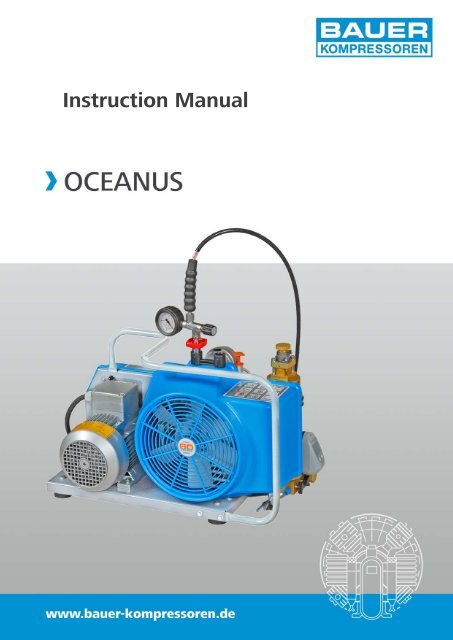
<strong>Instruction</strong> <strong>Manual</strong>
<strong>Instruction</strong> <strong>Manual</strong> � <strong>Oceanus</strong><br />
INTRODUCTION<br />
This manual contains operating instructions and maintenance<br />
schedules for the high pressure breathing air compressor<br />
unit<br />
<strong>Oceanus</strong><br />
WARNING<br />
! Pneumatic high pressure system !<br />
The breathing air produced with the compressor units described<br />
in this manual is subject to strict quality standards.<br />
Ignoring the operating and maintenance instructions can<br />
lead to severe injury or death.<br />
This compressor has been built in accordance with the EC<br />
machine regulations 2006/42/EG. Specifications on the<br />
noise level in accordance with the machine and product<br />
safety law as of May 2004 and the EC machine regulations,<br />
chapt. I, section 1.7.4. The machine has been built according<br />
to the highest standard of technology and the generally<br />
acknowledged safety standards. Nevertheless, operation<br />
could still cause danger for the operating personnel or<br />
third parties, or result in damage to the machine and other<br />
values. The machine may only be used to produce compressed<br />
air as specified in this manual. Other use is strictly<br />
prohibited.<br />
All instructions should be observed and carried out in the<br />
order laid down to prevent damage and premature wear<br />
to the equipment.<br />
The manufacturer and the supplier void all responsibility<br />
for damage or injury resulting from failure to follow these<br />
instructions.<br />
Edition January 2010<br />
� 2010 BAUER Kompressoren GmbH, München<br />
All rights reserved<br />
i
Dear customer<br />
We are happy to give you advice on any questions regarding<br />
your BAUER compressor and help as soon as possible<br />
with any arising problems.<br />
You can contact us Mondays to Thursdays from 08 00 till<br />
16 30 , Fridays from 08 00 till 14 00 on phone no. (089)<br />
78049-0.<br />
If you call the following extensions directly, it will save you<br />
time and continuous dialling.<br />
Do you want to order spare parts?<br />
� Customer service<br />
Phone no: (089) 78049-129 or -149<br />
Fax no: (089) 78049-101<br />
Explanation of the short operating instructions on the unit<br />
ii<br />
A<br />
B C<br />
Read instruction manual before<br />
operating unit<br />
� chapter 3.<br />
Check oil level on compressor and<br />
petrol engine before operating<br />
unit<br />
� chapter 4.4.1.<br />
Drain condensate at least every 15<br />
minutes (3 locations)<br />
� chapter 4.4.3. and 4.4.4.<br />
Position units with petrol engine<br />
with exhaust in wind direction to<br />
prevent exhaust fumes being<br />
sucked in by the compressor<br />
� chapter 3.<br />
Petrol driven units must not be operated<br />
indoors.<br />
� chapter 3.<br />
<strong>Instruction</strong> <strong>Manual</strong> � <strong>Oceanus</strong><br />
Do you have problems with maintenance or repair work?<br />
� Technical customer service<br />
Phone no: (089) 78049-176 or -246<br />
Fax no: (089) 78049-101<br />
Do you need further information regarding your unit, accessories,<br />
prices etc.?<br />
� Sales department<br />
Phone no: (089) 78049-138, -185, -154, -205 or -202<br />
Fax no: (089) 78049-103<br />
Are you interested in any training courses?<br />
� Training manager<br />
Phone no: (089) 78049-175<br />
Fax no: (089) 78049-103<br />
Or visit us in the inernet at:<br />
www.bauer-kompressoren.de<br />
�30<br />
Position unit level: max. inclination<br />
Electric unit: 30�<br />
Petrol unit: 20�<br />
� chapter 3.<br />
Operate unit only at ambient temperatures<br />
between +5 and<br />
+45 �C<br />
� chapter 3.<br />
Keep away from hot surfaces on<br />
motor and compressor<br />
� chapter 2.<br />
Wear ear protectors when unit is<br />
running<br />
� chapter 2.
<strong>Instruction</strong> <strong>Manual</strong> � <strong>Oceanus</strong><br />
CONTENTS<br />
1. GENERAL ............................ 1<br />
2. SAFETY MEASURES .................... 5<br />
3. LOCATION, OPERATION, BOTTLE FILLING .. 9<br />
4. MAINTENANCE ....................... 17<br />
5. STORAGE, PRESERVATION .............. 32<br />
6. REPAIR INSTRUCTIONS ................. 33<br />
7. TABLES .............................. 34<br />
8. ANNEX .............................. 35<br />
INDEX<br />
A<br />
Adhesive chart, 34<br />
Air flow diagram, 1<br />
Annex, 35<br />
B<br />
B-Timer, 13<br />
C<br />
Change of oil type, 18<br />
Change-over device, 12<br />
Cooling system, 29<br />
D<br />
Design, 1<br />
Drive system, 27<br />
E<br />
V-belt, tension meter, 27<br />
Electrical system, 28<br />
F<br />
Filling procedure, 10<br />
Filter system, 19<br />
I<br />
Intake filter, 18<br />
Intermediate separator, 19<br />
Intake air quality, 10<br />
L<br />
Location, 9<br />
Lubrication, 17<br />
Lubrication chart, 34<br />
M<br />
Maintenance, 17<br />
ANNEX<br />
Maintenance instructions, 17<br />
Maintenance record, 17<br />
Maintenance schedule, 17<br />
Motor protection switch, 28<br />
O<br />
Oil change, 17, 18<br />
Oil level check, 17<br />
Oil type, 17<br />
Operation, 9<br />
P<br />
Preservation, 32<br />
Pressure gauge, 25<br />
Pressure-maintaining valve, 24<br />
R<br />
Repair instructions, 33<br />
S<br />
Safety valves, 24<br />
Sealant chart, 34<br />
Shut-down, 12<br />
Storage, 32<br />
T<br />
Tables, 34<br />
Technical data, 4<br />
Telescopic intake tube, 18<br />
Testing agents, 34<br />
Tightening torque values, 34<br />
Torque sequence, 34<br />
Trouble-shooting, 30<br />
V<br />
Valves, 25<br />
Schematic diagram motor protection switch, three phase current KB 76942-992-S1<br />
Lubricating oil list KB 70851-994<br />
Applicable parts list TO-1/8<br />
iii
iv<br />
NOTES<br />
Model:<br />
Serial No..:<br />
Date of purchase:<br />
Dealer address / phone no.:<br />
<strong>Instruction</strong> <strong>Manual</strong> � <strong>Oceanus</strong>
<strong>Instruction</strong> <strong>Manual</strong> � <strong>Oceanus</strong><br />
1. GENERAL<br />
PURPOSE<br />
The <strong>Oceanus</strong> breathing air compressor is designed to compress<br />
air for breathing as required in diving applications.<br />
The max. allowable operating pressure (adjusted pressure<br />
on final pressure safety valve) is 225 bar (3,200 psi) or 330<br />
bar (4,700 psi).<br />
DESIGN<br />
The compressor unit comprises the following major assemblies:<br />
- compressor block<br />
- drive motor<br />
- filter system P21<br />
- filling assembly<br />
- base plate and frame<br />
The design of the compressor system is shown in Fig. 1 to<br />
Fig. 4.<br />
1<br />
2<br />
3<br />
4<br />
5<br />
6<br />
7<br />
8<br />
9<br />
Fig. 1 Compressor unit with petrol engine<br />
1 Filling hose<br />
2 Exhaust<br />
3 Air filter<br />
4 Tank<br />
5 Throttle lever<br />
6 Choke lever<br />
7 Fuel cock<br />
AIR FLOW DIAGRAM<br />
See Fig. 5 . The air is drawn in through telescopic tube<br />
(necessary for units with petrol engine) -1, intake filter -2;<br />
compressed to final pressure in cylinders -3, -4, -5; recooled<br />
by intercoolers -6, -7, and aftercooler -9. The pressures of<br />
the single stages are protected by safety valves -10, -11,<br />
-12. The compressed air is pre-cleaned in intermediate separator<br />
-8 and purified in filter system P21 -13. Intermediate<br />
separator and filter system P21 are drained by means of<br />
condensate drain valves -15. Pressure maintaining valve -16<br />
provides a constant pressure within the filter assembly. The<br />
compressed, purified air is passed through filling hose -17<br />
and filling valve -18 to the bottles to be filled. Filling pressure<br />
is indicated at pressure gauge -19. With change over<br />
device it is possible to fill bottles with 200 bar nominal pressure<br />
by opening valve -21 at filling valve -18. Safety valve<br />
-20 is adjusted to a blow off pressure of 225 bar.<br />
8 Starter rope<br />
9 Engine stop switch (ignition)<br />
10 Filling valve with final pressure gauge<br />
11 Safety valve, final pressure<br />
12 Filter system P21<br />
13 B-Timer<br />
14 Condensate drain taps<br />
1
2<br />
1 Filling hose<br />
2 Filling valve with pressure gauge<br />
3 Motor terminal box<br />
4 Three-phase motor<br />
5 Final pressure safety valve<br />
6 Handle<br />
7 Fanwheel cover<br />
8 B-Timer<br />
9 Condensate drain valves<br />
10 Mains plug with ON-OFF switch and motor<br />
protection circuit breaker (dep. on country)<br />
10<br />
Fig. 2 Compressor unit with electric motor (three-phase current)<br />
1 Filling hose<br />
2 Filling valve with pressure gauge<br />
3 Motor terminal box with ON-OFF switch<br />
4 Single-phase motor<br />
5 Final pressure safety valve<br />
6 Handle<br />
7 Fanwheel cover<br />
8 Pressure maintaining valve<br />
9 Condensate drain valves<br />
Fig. 3 Compressor unit with electric motor (alternating current)<br />
3<br />
4<br />
4<br />
3<br />
<strong>Instruction</strong> <strong>Manual</strong> � <strong>Oceanus</strong><br />
2<br />
1<br />
1<br />
2
<strong>Instruction</strong> <strong>Manual</strong> � <strong>Oceanus</strong><br />
1<br />
2<br />
3<br />
4<br />
5<br />
Fig. 4 Compressor block <strong>Oceanus</strong><br />
10<br />
1 Telescopic air intake<br />
2 Intake filter<br />
3 Cylinder 1st stage<br />
4 Cylinder 2nd stage<br />
5 Cylinder 3rd stage<br />
6 Inter-cooler 1st/2nd stage<br />
7 Inter-cooler 2nd/3rd stage<br />
1<br />
2<br />
3<br />
4 5<br />
Fig. 5 Air flow diagram<br />
6<br />
7<br />
9<br />
15<br />
8<br />
11<br />
8 Intermed. separator 2nd/3rd stage<br />
9 After-cooler<br />
10 Safety valve 1st stage<br />
11 Safety valve 2nd stage<br />
12 Final pressure safety valve<br />
13 Filter system P21<br />
14 TRIPLEX longlife cartridge<br />
12<br />
6<br />
7<br />
8<br />
9<br />
10<br />
11<br />
12<br />
15<br />
1 Intake filter<br />
2 Inter-cooler 1st stage<br />
3 Safety valve 1st stage<br />
4 Cylinder 2nd stage<br />
5 Inter-cooler 2nd stage<br />
6 Oil dipstick<br />
7 Safety valve 2nd stage<br />
8 Intermediate separator 2nd stage<br />
9 Cooling air fan<br />
10 After-cooler<br />
11 Compressed air outlet<br />
12 Condensate drain tap<br />
13<br />
14<br />
16<br />
18<br />
17<br />
21<br />
20<br />
19<br />
18<br />
17<br />
15 Condensate drain valve<br />
16 Pressure maintaining valve<br />
17 Filling hose<br />
18 Filling valve<br />
19 Final pressure gauge<br />
20 Safety valve, final pressure PN 200<br />
21 Change over device (optional extra)<br />
19<br />
3
TECHNICAL DATA<br />
4<br />
<strong>Instruction</strong> <strong>Manual</strong> � <strong>Oceanus</strong><br />
Compressor unit <strong>Oceanus</strong>-1 <strong>Oceanus</strong>-B <strong>Oceanus</strong>-E <strong>Oceanus</strong>-W<br />
Medium air<br />
Delivery a) 140 l/min.<br />
Operating pressure --- PN 200/300 PN 200/300 PN 200/300<br />
Pressure setting, final pressure safety valve --- 225 / 300 bar 225 / 330 bar 225 / 330 bar<br />
Sound pressure --- 87 dB(A) 86 dB(A) 86 dB(A)<br />
Sound (immersion) power --- 100 dB(A) 99 dB(A) 99 dB(A)<br />
Dimensions LxWxH (mm) 655x300x415 790x350x415 655x400x415 655x400x415<br />
Weight 31 kg 47 kg 52 kg 52 kg<br />
Compressor block <strong>Oceanus</strong>, mod. 1<br />
Number of stages 3<br />
Number of cylinders 3<br />
Cylinder bore 1st stage 70 mm<br />
Cylinder bore 2nd stage 28 mm<br />
Cylinder bore 3rd stage 12 mm<br />
Piston stroke 24 mm<br />
Speed 2,300 min -1<br />
Intermediate pressure 1st stage --- 6.5 / 7 bar<br />
Intermediate pressure 2nd stage --- 52 / 61 bar<br />
Compressor block oil capacity 1.3 ltrs.<br />
Oil volume between min. and max. 200 ml<br />
Oil type see chapter 4.4.1. lubrication<br />
Max. ambient temperature +5 ... +45 �C<br />
Max. inclination of compressor b) 30� 20� 30�<br />
Max. operating height 0 ... 2000 m above sea level<br />
Compressor drive <strong>Oceanus</strong>-B<br />
Drive motor Robin/Subaru petrol engine<br />
<strong>Manual</strong> start model (B) EX21<br />
Power 5 kW (7 h.p.)<br />
at nominal speed 3,600 min -1<br />
Compressor drive <strong>Oceanus</strong>-E<br />
Drive motor Three phase current<br />
Operating voltage 400-415 V, 50-60 Hz or 440-480V, 50-60 Hz<br />
Power 3.0 kW<br />
Speed 2,850 min -1<br />
Size 90 L<br />
Type of construction B3<br />
Type of enclosure IP54<br />
Compressor drive <strong>Oceanus</strong>-W<br />
Drive motor Alternating current<br />
Operating voltage 230 V, 50 Hz<br />
Power 3.0 kW<br />
Speed 3,000 min -1<br />
Size 100<br />
Type of construction B3<br />
Type of enclosure IP54<br />
a) free air delivered at bottle filling from 0 to 200 bar � 5%.<br />
b) these values are valid only if the compressor in normal position corresponds with the upper mark of the oil dipstick and may not be<br />
exceeded.
MV3−A/10/06<br />
<strong>Instruction</strong> <strong>Manual</strong> � <strong>Oceanus</strong><br />
2. SAFETY MEASURES<br />
2.1. NOTES AND WARNING SIGNS<br />
Notes and warning signs displayed on compressors according<br />
to model, application or equipment.<br />
WARNING<br />
Hot surfaces, do not touch!<br />
Danger of burning by touching cylinders,<br />
cylinder heads and pressure lines of individual<br />
compressor stages.<br />
WARNING<br />
High voltage!<br />
Life threatening danger of electric shock.<br />
Maintenance work on electric units or operating<br />
equipment may only be carried<br />
out by a qualified electrician or by a person<br />
instructed and supervised by a qualified<br />
electrician according to electrical regulations.<br />
WARNING<br />
Automatic compressor control, unit may<br />
start-up without warning!<br />
Before carrying out maintenance and repair<br />
work, switch off at the main switch or<br />
disconnect from the mains and ensure<br />
unit will not restart.<br />
MANDATORY<br />
<strong>Instruction</strong>s must be read by persons operating<br />
the machinery!<br />
The instruction manual supplied and all<br />
other applicable instructions, regulations<br />
etc. must be read and understood by operating<br />
personnel before using the machine.<br />
MANDATORY<br />
Hearing protectors must be worn!<br />
Hearing protectors must be worn when<br />
working on a machine which is running.<br />
NOTE<br />
Ensure correct direction of rotation!<br />
When switching on the machine, check<br />
the arrow to ensure correct direction of<br />
rotation of the drive motor.<br />
2.2. IDENTIFYING THE SAFETY NOTICES<br />
Important instructions concerning the endangerment of<br />
personnel, technical safety and operating safety will be<br />
specially emphasized by placing the following signs before<br />
the instructions.<br />
This notice is used with maintenance<br />
WARNING work and operating procedures and<br />
must be adhered to exactly in order to<br />
avoid endangering personnel.<br />
This notice must be complied with in order to<br />
avoid damage to or destruction of the machine<br />
or its equipment.<br />
This notice advises of technical requirements<br />
which the operator must take particular note<br />
of.<br />
2.3. FUNDAMENTAL SAFETY NOTICES<br />
2.3.1. Authorized use<br />
� The machine / unit is built according to state of the art<br />
technology and established safety technical regulations.<br />
Nevertheless, its use can cause danger to life and<br />
limb of the operator or third parties or damage to the<br />
machine and other equipment.<br />
� Operate the machine / unit only in technically perfect<br />
condition in accordance with regulations and safety and<br />
danger notices detailed in the instruction manual! In<br />
particular, immediately correct faults (or have them corrected)<br />
which can impair safety!<br />
� The machine / unit is exclusively for the compression of<br />
mediums (air/gas) specified in section A, chapter 1.3.<br />
“Technical data”. Any other medium or use outside that<br />
specified is not authorized. The manufacturer / supplier<br />
is not liable for damage resulting from this. The user<br />
alone is responsible for this risk. Authorization for use<br />
is also under the condition that the instruction manual<br />
is complied with and inspection and maintenance requirements<br />
are enforced.<br />
2.3.2. Organizational measures<br />
� Keep the instruction manual to hand near the machine<br />
/ unit at all times in the relevant holder.<br />
� In addition to the instruction manual, observe and comply<br />
with universally valid legal and other obligatory regulations<br />
regarding accident prevention and environment<br />
protection. See chapter 2.4. This can involve, for<br />
example, contact with hazardous substances or the<br />
provision / wearing of personal protective equipment.<br />
� Personnel engaged to operate the machine must have<br />
read the instruction manual before beginning work, especially<br />
the safety notices chapter. When work is already<br />
underway it is too late. This is particularly relevant<br />
for temporary personnel, e.g. maintenance personnel.<br />
� Personnel may not wear long hair loose, loose clothing<br />
or jewellery, including rings. There is a danger of injury<br />
through, for example, these getting caught or being<br />
pulled into the equipment.<br />
5
� As far as necessary or according to regulations, use personal<br />
protective equipment.<br />
� Observe all safety and danger notices on the unit.<br />
� Keep all safety and danger notices on the machine / unit<br />
complete and in readable condition.<br />
� If there are any modifications to the unit or operating<br />
conditions which may affect safety, stop the unit immediately<br />
and inform the person responsible of the<br />
fault.<br />
� No modifications may be made to the unit which could<br />
impair safety without first obtaining permission from<br />
the suppliers. This is also the case with regard to installation<br />
and adjustment of safety devices and valves as well<br />
as welding of piping and reservoirs.<br />
� Spare parts must always comply with the technical requirements<br />
specified by the manufacturer. This is always<br />
guaranteed with original spare parts.<br />
� Piping must be thoroughly checked (pressure and visual<br />
inspection) by the operator at appropriate time intervals,<br />
even if no safety related faults have been noticed.<br />
� Intervals stipulated or given in the instruction manual for<br />
recurring checks / inspections must be adhered to.<br />
� Make sure location and operation of fire extinguishers<br />
is known.<br />
� Pay attention to fire warning and fire fighting procedures.<br />
2.3.3. Qualifications, fundamental duties<br />
� Work on / with the unit may only be carried out by reliable<br />
personnel. Observe the legal minimum age permissible.<br />
� Ensure that only trained personnel work with the machine.<br />
� Establish the responsibilities of the machine operator<br />
and establish a procedure for him to inform a third person<br />
of unfavourable safety conditions.<br />
� People who are being trained or introduced to the job<br />
should only be allowed to work with the unit under constant<br />
supervision of an experienced person.<br />
� Work on the electrical equipment of the unit may only<br />
be carried out by a qualified electrician or by an instructed<br />
person under the direction and supervision of<br />
a qualified electrician according to electrotechnical regulations.<br />
2.3.4. Safety notices for operation<br />
� Do not carry out any work if safety is questionable.<br />
� Meet all requirements demanding that the unit is only<br />
operated in safe and good working order. Only operate<br />
the machine if all protective and safety equipment, e.g.<br />
all detachable protective equipment, emergency shutdown<br />
devices, soundproofing is provided and in good<br />
working order.<br />
� At least once every day, check the unit externally for<br />
damage and faults. Inform the person responsible im<br />
6<br />
<strong>Instruction</strong> <strong>Manual</strong> � <strong>Oceanus</strong><br />
mediately if anything is not as is should be (including<br />
operation). If necessary, shut the machine down immediately<br />
and make it safe.<br />
� Observe switching on and off processes and monitoring<br />
indications according to the instruction manual.<br />
� Before switching on / starting up the unit, ensure that no<br />
one can be put at risk through running the unit.<br />
� Carry out the setting, maintenance and inspection processes<br />
at the intervals specified in the instruction manual,<br />
including replacement of parts / equipment. This<br />
work may only be carried out by qualified personnel.<br />
� Clear and make the maintenance area safe as far as<br />
necessary.<br />
� If the unit is completely switched off for maintenance<br />
and repairwork, ensure that it is protected from unexpected<br />
start-up. Turn off main control device and remove<br />
the key and / or display a warning sign on the main<br />
switch.<br />
� When replacing individual parts and larger assembly<br />
groups, they must be carefully fastened to the lifting device<br />
so that there is no risk of danger. Use only suitable<br />
and technically perfect lifting devices and equipment<br />
with sufficient lifting power and strength. Do not linger<br />
or work under suspended loads.<br />
� Only entrust an experienced person with the fixing of<br />
loads and guiding of crane drivers. The person guiding<br />
must remain within sight or in contact with the operator.<br />
� For assembly work above body height, use appropriate<br />
safety approved equipment, e.g. ladders and platforms.<br />
Do not climb on machine parts. For maintenance work<br />
at high levels, wear a safety harness.<br />
� Clean oil, fuel or care products from the machine, in particular<br />
the connections and screw joints, before carrying<br />
out maintenance / repairwork. Do not use aggressive<br />
cleaning fluid. Use a fibre-free cleaning cloth.<br />
� Before cleaning the machine with water or jet of steam<br />
(high pressure cleaner) or detergent, cover / seal all<br />
openings which for safety and/or operating reasons no<br />
water / steam / detergent may penetrate. Electric motor<br />
and switch cabinets are particularly at risk.<br />
� When cleaning the operating room, ensure that the<br />
temperature sensors of the fire alarm and sprinkler system<br />
do not come into contact with hot cleaning fluid,<br />
in order to avoid triggering the sprinkler system.<br />
� Completely remove all covers / seals after cleaning.<br />
� After cleaning, check all pressure lines for leaks, loose<br />
connections, wear and damage. Immediately eliminate<br />
any faults.<br />
� Always retighten any screw connections loosened for<br />
maintenance or repairwork.<br />
� If it is necessary to remove safety devices for maintenance<br />
and repairwork, these must be replaced and<br />
checked immediately after completion of the maintenance<br />
or repairwork.<br />
� Ensure safe and environmentally friendly disposal of<br />
consumables and old parts.
<strong>Instruction</strong> <strong>Manual</strong> � <strong>Oceanus</strong><br />
2.3.5. Particular areas of danger<br />
� Use only original fuses with specified current rating. If<br />
there is a failure in the electric energy supply, shut the<br />
unit down immediately.<br />
� Work on electric units or operating equipment may only<br />
be carried out by a qualified electrician or by a person<br />
under the instruction and supervision of a qualified electrician<br />
according to electric technical regulations.<br />
� Machines and unit parts which must undergo inspection,<br />
maintenance and repairwork, must be disconnected<br />
from the mains supply, if specified. Parts which<br />
have been disconnected must first be checked for voltage,<br />
then earthed and short-circuited and isolated from<br />
live neighbouring parts.<br />
� The electrical equipment of a unit must be regularly<br />
checked. Defects, such as loose screw connections or<br />
burnt wires, must be rectified immediately.<br />
� If work is to be carried out on live parts, work with a second<br />
person who can operate the emergency off switch<br />
or the main switch in the case of an emergency. Close<br />
off the work area with a red and white safety chain and<br />
a warning sign. Only use voltage isolated tools.<br />
� Only personnel with particular knowledge and experience<br />
with pneumatics may carry out work on pneumatic<br />
equipment.<br />
� Check all pressure lines, hoses and screw connections<br />
regularly for leaks and visible damage. Immediately repair<br />
any damage. Escaping air under pressure can cause<br />
injury and fire.<br />
� Depressurize system and pressure lines before commencing<br />
repairwork.<br />
� Pressurized air lines must be laid and mounted by qualified<br />
personnel. Connections must not be mixed up. Fittings,<br />
length and quality of the piping must correspond<br />
to requirements.<br />
� Soundproofing equipment on the unit must be in place<br />
and functional during operation.<br />
� The stipulated hearing protectors must be worn.<br />
� With regard to oil, grease and other chemical substances,<br />
observe the relevant safety regulations for the<br />
product.<br />
� For loading, only use lifting device and equipment with<br />
sufficient lifting power and strength.<br />
� Use only suitable transporters with sufficient carrying<br />
power. Secure the load properly. Use suitable fixing<br />
points.<br />
� If necessary, provide unit with transportation brackets.<br />
Display the appropriate notice. Remove transportation<br />
brackets in the correct manner before taking into operation.<br />
� Parts which need to be dismantled for transport purposes<br />
must be carefully replaced and secured before<br />
taking into operation.<br />
� Even when moving the unit only slightly, the unit must<br />
be disconnected from all external energy sources. Be<br />
fore putting into use again, reconnect the machine to<br />
the mains according to regulations.<br />
� When taking back into operation, proceed according to<br />
the instruction manual.<br />
2.3.6. Notices of danger regarding pressure vessels<br />
� Never open or loosen pressure vessel lids or pipe connection<br />
parts under pressure; always depressurise the<br />
vessel or the unit.<br />
� Never exceed the permissible operating pressure of the<br />
vessels!<br />
� Never heat the vessels or any of their parts above the<br />
stated, maximum operating pressure.<br />
� Always exchange damaged pressure vessels completely.<br />
Individual parts that are subject to pressure<br />
loads cannot be purchased as spare parts, since the<br />
vessels are tested as a complete part and the documentation<br />
considers them as a whole (see pressure<br />
vessel documentation, serial-numbers!).<br />
� Always pay attention to the permissible operating mode<br />
of the pressure vessels.<br />
We differentiate:<br />
- vessels for static load<br />
- vessels for dynamic load<br />
Vessels for static load:<br />
These pressure vessels are permanently under virtually<br />
constant operating pressure; the fluctuations of pressure<br />
are very small.<br />
Vessels for this type of load are not marked in a particular<br />
way and may be used as long as the vessel inspections,<br />
carried out regularly, do not uncover any safetyrelevant<br />
deficiencies.<br />
We recommend that aluminium vessels should be<br />
exchanged after 15 years at the latest.<br />
Vessels for dynamic load:<br />
These pressure vessels may also be used under conditions<br />
of changing operating pressure. The pressure may<br />
vary between the atmospheric and the maximum admissible<br />
operating pressure.<br />
The pressure vessel documentation and the appropriate<br />
notes in the operating manual particularly characterise<br />
vessels of this type as being adequate for dynamic loads.<br />
In the technical information for these vessels you will<br />
find specifications concerning their permissible operating<br />
period.<br />
Due to the variation of the operating pressure, these<br />
vessels are subject to a so-called dynamic load, which<br />
puts the vessels under great stress. The change between<br />
two different pressures is called a load change or cycle.<br />
In the technical information for these vessels you will<br />
find specifications concerning the permissible number<br />
of cycles depending on the fluctuation of the operating<br />
pressure.<br />
Having reached half the permissible number of cycles,<br />
the vessel has to be submitted to an internal check, in<br />
which the critically stressed areas of the vessels are<br />
7
examined by means of suitable testing methods, in<br />
order to ensure the operating safety.<br />
After having reached the total permissible number of<br />
load cycles, the vessel must be exchanged and<br />
scrapped.<br />
Record the number of load cycles in writing if you do not<br />
have an automatic cycle-counter.<br />
We recommend that aluminium vessels should be<br />
exchanged after 15 years at the latest.<br />
Please pay attention to and follow these measures, for<br />
your own safety and that of you employees and customers!<br />
In order not to unnecessarily load the pressure vessels<br />
additionally, the non-return valves, that are meant to<br />
avoid a drop in pressure, and also the pressure maintaining<br />
valves, which should reduce big pressure fluctuations<br />
as well, should be checked regularly for internal<br />
and external tightness and functionality.<br />
� Check the pressure vessels regularly on the inside and<br />
outside for damage from corrosion.<br />
� Be particularly careful with second-hand pressure<br />
vessels, when their previous operating mode is not specifically<br />
clarified.<br />
2.4. SAFETY REGULATIONS (EC; partly Germany,<br />
only)<br />
A compressor is identified by German law as being a filling<br />
system if pressure cylinders are filled by the system, especially<br />
when these cylinders are made available for third<br />
parties. The start-up and operation of compressor systems<br />
for use as filling stations is governed by the following regulations:<br />
Pressure vessel directive (Directive 97/23/EC) of<br />
29.05.1997<br />
Operating safety regulations (BetrSichV) of<br />
27.09.2002<br />
Machine safety law (GSG) of 11.05.2001<br />
14th regulation to machine safety law (14. GSGV -<br />
pressure vessel regulation) of 03.10.2002<br />
Technical regulations for pressure gases (TRG 400,<br />
401, 402, 730).<br />
If a high pressure compressor is used for filling pressure<br />
vessels or for the supply of pneumatic systems, the following<br />
regulations apply:<br />
Accident Prevention Regulations (UVV):<br />
BGV A1 of 01. January 2004<br />
8<br />
<strong>Instruction</strong> <strong>Manual</strong> � <strong>Oceanus</strong><br />
Copies of the above regulations are available through the<br />
usual outlets, e.g. in Germany from:<br />
Carl Heymanns Verlag<br />
Luxemburger Str. 449<br />
50939 Köln<br />
Beuth-Vertrieb GmbH<br />
Burggrafenstr. 4 - 7<br />
10787 Berlin<br />
The manufacturer has complied with all applicable regulations<br />
and the unit is prepared accordingly. If desired, we<br />
offer at our Munich site a partial acceptance test according<br />
to § 14 BetrSichV. Please contact our Technical Service Department<br />
with regard to this. They can also supply our<br />
leaflet “IMPORTANT NOTES FOR CERTIFICATION”.<br />
According to the operation safety regulations (BetrSichV),<br />
all compressor units which will be used as filling stations<br />
must undergo an acceptance test by a professional at their<br />
location before bringing them into service. If pressure<br />
vessels (bottles) are to be filled by the compressor for a third<br />
party then the appropriate permission must be obtained<br />
from the responsible authority before the acceptance test.<br />
As a rule, this is the factory inspectorate. The procedure for<br />
obtaining permission is according to TRG 730, guidelines<br />
for permission to set up and operate filling stations. The test<br />
certificates and documents delivered with the compressor<br />
are important and may be requested during the procedure<br />
for obtaining permission. In addition, the documents belonging<br />
to the unit are important for recurrent inspections<br />
and should therefore be carefully kept.<br />
Inspections in accordance with the regulations for prevention<br />
of accidents will be carried out by the manufacturer or<br />
by a specialist.<br />
No guarantees whatsoever are valid for damage caused or<br />
favoured by the non-consideration of these directions for<br />
use.<br />
We strongly emphasize these regulations.
<strong>Instruction</strong> <strong>Manual</strong> � <strong>Oceanus</strong><br />
3. LOCATION, OPERATION, BOTTLE FILLING<br />
LOCATION<br />
Outdoor location<br />
The compressor unit is not seawater resistant.<br />
At operation in salty air spray<br />
compressor with anticorrosive protection<br />
(e. g. Quicksilver Corrosion Guard).<br />
Electric driven units should be operated<br />
and stored below deck. Units with petrol engine<br />
should also be stored below deck after the filling process.<br />
WARNING<br />
WARNING<br />
Keep unit away from inflammable<br />
items. Do not smoke while petrol<br />
tank is open and while unit is in<br />
operation.<br />
- Locate the unit level.<br />
- On units with petrol engine it is most important that only<br />
clean air be used, position compressor in direction of<br />
wind so that exhaust fumes are blown away from the<br />
unit.<br />
- Turn unit as soon as wind direction changes.<br />
- Take care that no vehicles are in direct vicinity with engines<br />
running.<br />
- Do not operate unit in the vicinity of open fire (flue gas!).<br />
Indoor location<br />
Petrol driven units must not be operated<br />
indoors.<br />
- Ensure adequate ventilation.<br />
- Here too, air must be free from exhaust fumes and hazardous<br />
vapours (e.g. smoke, solvent vapours, etc.).<br />
- If possible install unit in such a manner that the compressor<br />
fan can get fresh air from outside, for instance<br />
through an opening in the wall.<br />
- Ensure that an adequate exhaust air opening is provided.<br />
- When locating the compressor in small rooms where<br />
natural ventilation is not ensured, measures must be<br />
taken to provide artificial ventilation (this also applies<br />
when other systems having high radiation are operating<br />
in the same room).<br />
Electrical installation<br />
For installation of electrical equipment observe the following:<br />
- Comply with regulations of local electricity supply company.<br />
- Arrange for the electrics to be connected by an electrician<br />
only.<br />
- Ensure correct installation of protective conductor.<br />
- Check conformity of motor tension and frequency with<br />
those of electric network.<br />
- Operate electric units only on mains sockets equipped<br />
with fault current circuit breaker according to DIN VDE<br />
0664 with a nominal differential current of less than 30<br />
mA (up to 16 A in single-phase AC circuits).<br />
- For units not connected through a plug, but permanently<br />
installed, a main switch must be provided which<br />
has a contact gap of minimum 3 mm on each pole.<br />
- Fuse motor correctly; use slow-blow fuses, only.<br />
- Immediately after start-up check direction of rotation<br />
for agreement with arrow on unit.<br />
If power supply cable is to be replaced,<br />
use cable of same type, only!<br />
- When using extension leads or cable drums, operate<br />
unit with unwound cable, only to avoid overheating and<br />
risk of fire. The maximum length for extension cables at<br />
normal ambient temperatures (approx. 20 �C) is 25 metres.<br />
OPERATION<br />
Preparation for operation<br />
All compressor units are tested prior to<br />
delivery to the customer, so after correct<br />
installation of the unit there should be no<br />
problem putting it into operation, observing the following<br />
points:<br />
The compressors described in this<br />
WARNING manual are not suitable for compression<br />
of oxygen. EXPLOSION<br />
occurs if an oil lubricated compressor is operated with<br />
pure oxygen or gases with an oxygen content of more<br />
than 21%!<br />
- Prior to first operation read <strong>Instruction</strong> <strong>Manual</strong> carefully.<br />
Make sure that all persons handling the compressor and<br />
the filling station are familiar with the function of all controls<br />
and monitors. Particularly observe chapter 2<br />
SAFETY REGULATIONS.<br />
- After taking unit into operation after a standstill period<br />
of 2 years or more change compressor oil. When using<br />
a mineral oil change oil after one year.<br />
- Prior to first operation or operation subsequent to repair<br />
work operate unit for at least 5 minutes with open<br />
condensate valves (pressureless) to ensure proper lubrication<br />
of all parts before pressure is built up.<br />
- Prior to each operation check the oil level according to<br />
chapter 4.4.1. and determine whether maintenance is<br />
necessary in accordance with chapter 4.3.<br />
9
- Every time the unit is started up check all systems for<br />
proper operation. If any malfunction is observed stop<br />
unit immediately and find the cause of the fault or call<br />
the service department.<br />
Units with three phase current motor, additionally:<br />
- Immediately after switching on the system for the first<br />
time check the direction of rotation of the motor for<br />
compliance with the arrow on the unit. If motor turns in<br />
the wrong direction, the phases are not connected<br />
properly. Shut down unit immediately and interchange<br />
two of the three phase leads in the switch box. Never<br />
change leads at the motor terminal board.<br />
Units with petrol engine, additionally:<br />
- Check engine oil level according to manufacturer's instruction<br />
manual.<br />
- Check fuel tank. Top up if necessary.<br />
- Open fuel shut-off valve.<br />
Starting the unit (Petrol and Electric):<br />
- Open condensate drain valves on the filters to release<br />
pressure so that motor starts without load.<br />
Units with electric drive motor:<br />
- Three-phase current: the motor is switched on manually<br />
by turning the switch (1, Fig. 6) to 1.<br />
10<br />
1<br />
Fig. 6 Motor protection switches<br />
(three-phase motor)<br />
- Alternating current: Set 0-I switch to I.<br />
Units with petrol engine:<br />
- Set choke to position START. Start engine with recoil<br />
starter or crank handle. As soon as motor runs smoothly<br />
return choke to normal operating position.<br />
All units:<br />
- Close condensate drain valves and run unit to final pressure.<br />
Check final pressure safety valve and pressure<br />
gauge.<br />
<strong>Instruction</strong> <strong>Manual</strong> � <strong>Oceanus</strong><br />
- As soon as final pressure is reached and final pressure<br />
safety valve blows off, open condensate drain valves<br />
and drain condensate - unit is ready for filling operation.<br />
Observe regular condensate drain acc. to chapter<br />
“Maintenance”.<br />
FILLING PROCEDURE<br />
General<br />
Ensure intake air is free from<br />
WARNING noxious gas (CO), exhaust fumes<br />
and solvent vapour. On units employing<br />
petrol or diesel engine it is most important to<br />
use an intake hose and observe that only clean air is<br />
drawn in. The intake hose is also recommended for<br />
units with electric engine. When operating the unit in<br />
areas with possibly high CO contents, the CO removal<br />
filter cartridge is recommended for electric driven<br />
units, also. Note that for CO contents of more than 25<br />
ppmV in the intake air the allowed limits cannot be<br />
guaranteed even with a CO removal filter cartridge,<br />
resulting in a life-threatening CO concentration! Also,<br />
due to chemical reaction of CO with hopcalite, warming<br />
up of the cartridge and danger of fire may result.<br />
Filling hoses must be in satisfac<br />
WARNING tory condition and threads undamaged.<br />
Pay particular attention to<br />
damage on the interface from hose fitting to hose. If<br />
the casing is scored, hose must be discarded.<br />
The filling valve connection is of the manual type and permits<br />
connection to air tanks without using tools. An O-ring<br />
is provided for self-sealing due to internal overpressure.<br />
Compressed air tank filling valves for a pressure in excess of<br />
200 bar are standardized (DIN 477, sheet 5) and connectors<br />
for 200 and 300 bar are different and cannot be mixed up.<br />
The use of adapters is not allowed!<br />
To ensure safe air tank removal after filling, the valve has an<br />
integral venting bore. Therefore always close tank valve<br />
first before closing filling valve. During filling procedure<br />
bottles will warm up due to recompression. After removing,<br />
allow to cool down, bottles may then be reconnected and<br />
topped up to the respective maximum filling pressure.<br />
To meet the CO2 maximum rating<br />
WARNING value in breathing air bottles,<br />
please observe the two following<br />
chapters ”Intake air quality” and ”Scavenging the<br />
compressor unit”.<br />
Intake air quality<br />
At routine tests, CO2 values beyond the permissible values<br />
are noted from time to time. Closer investigations often<br />
show that the compressed air is taken from rooms in which<br />
one or more persons are working. At insufficient ventilation,<br />
the CO2 value in the surrounding air can increase quite<br />
fast because of the exhaling of CO2. CO2 values from 1,000<br />
to 5,000 ppmv in workrooms are not unusual (MAK-value<br />
(max. workroom concentration) is 5,000 ppmv). Another
<strong>Instruction</strong> <strong>Manual</strong> � <strong>Oceanus</strong><br />
additional increase is caused by cigarette smoking, producing<br />
approx. 2g CO2 (� 2,000 ppmv) per cigarette. These<br />
pollutions add up to the basic pollution of approx. 400<br />
ppmv. The technically caused excessive increase of CO2<br />
during the filling process and the CO2 peak at taking the<br />
unit into operation. Because of the reasons stated<br />
above and for your own security, the filling of breathing<br />
air bottles is not allowed in rooms used as workrooms.<br />
Scavenging the compressor unit<br />
CO2 is present in the atmosphere with a natural amount of<br />
350 to 400 ppmV. The molecular sieve used in the purifier<br />
for drying the breathing air is, as well as other capabilities,<br />
able to adsorb CO2 which is accumulated in the cartridge.<br />
After shut-down of the compressor, adsorbed CO2 may be<br />
desorbed again due to the partial pressure decrease. The<br />
now free CO2 then gets washed out of the cartridge when<br />
the compressor is started again. To avoid increased CO2<br />
contents in the compressed breathing air, we recommend<br />
to flush the compressor unit 1 to 2 minutes prior to connecting<br />
the bottles, i.e. to let the air escape into the surroundings.<br />
Connecting the bottles<br />
tank neck).<br />
On models of 300 bar rated filling pressure<br />
do not attach bottles unless rated for<br />
this pressure (note pressure stamped on<br />
- Connect air bottle to filling valve (see Fig. 7).<br />
- Air bottles with international filling connector can be<br />
connected with filling adaptor (part no. 79375) to the<br />
German filling connector (see Fig. 8).<br />
The international connector is not permitted<br />
in the Federal Republic of Germany.<br />
In other countries it is allowed only<br />
for pressures up to 200 bar (2,850 psi).<br />
Filling the bottles<br />
- Open filling valve (1, Fig. 9).<br />
- Open bottle valve (2) - bottle will be filled. Drain condensate<br />
regularly during filling. On units with automatic<br />
condensate drain check that condensate is drained regularly.<br />
The filling procedure should not be interrupted<br />
for more than 10 minutes to avoid<br />
increased CO2-values in the air filled into<br />
the bottles.<br />
Fig. 7 Connecting air bottle<br />
Fig. 8 International filling connector<br />
Fig. 9 Filling air bottle<br />
1.<br />
2.<br />
Fig. 10 Removing air bottle<br />
2.<br />
1.<br />
11
Removing the bottles<br />
- Upon reaching final bottle pressure close bottle valve<br />
first (1, Fig. 10), then filling valve by returning handle<br />
to closed position (2).<br />
- Remove compressed air bottle.<br />
CHANGE-OVER DEVICE PN 300/PN 200<br />
(Fig. 11) This device allows bottle filling to 200 bar<br />
(3,200 psig) with a 300 bar (4,700 psig) rated unit. Safety<br />
valve -B and filling device PN 200 bar are connected by<br />
opening change-over valve -A and the connected bottles<br />
can be filled with a 200 bar pressure, as described in ”Filling<br />
the bottles”.<br />
Depressurize unit before opening valve -A<br />
to avoid damage to the change-over device<br />
SHUT-DOWN PROCEDURE<br />
- Close filling valve.<br />
Units with electric motor:<br />
- Three-phase current: the motor is switched off by<br />
turning the switch (1, Fig. 12) to 0.<br />
- Alternating current: set 0 - I switch to 0.<br />
Units with petrol engine:<br />
- Shut down petrol engine with stop button or stop lever.<br />
All units:<br />
- Drain condensate from intermediate separator and<br />
Triplex filter by means of the drain taps. Vent unit by<br />
means of filling valve to approx. 80 bar (1,150 psi). Close<br />
all valves again to prevent moisture entering the filter<br />
and resulting saturation of the cartridge.<br />
- Check the oil level in the compressor and top up, if<br />
necessary. Also check whether the compressor needs<br />
servicing in accordance with maintenance schedule -<br />
see chapter 4.3.<br />
12<br />
<strong>Instruction</strong> <strong>Manual</strong> � <strong>Oceanus</strong><br />
B<br />
Fig. 11 Change-over device<br />
1<br />
Fig. 12 Motor protection switches<br />
(three-phase motor)<br />
A
<strong>Instruction</strong> <strong>Manual</strong> � <strong>Oceanus</strong><br />
B-TIMER (optional)<br />
Introduction<br />
Read operating instructions carefully before operating the<br />
unit.<br />
The settings in the setup menu are essential<br />
for the correct indication of the filter<br />
capacity. Without correct settings, the B-<br />
Timer can be used as an hourmeter, only!<br />
Make sure that the pressure maintaining<br />
valve of the compressor is adjusted to<br />
150 bar (factory setting, see chapter<br />
4.4.5.) and is working properly to ensure correct indication<br />
of the filter capacity and compressor operation<br />
recognition.<br />
Make sure that all maintenance counter<br />
(a+b+c) were reset directly before the<br />
delivery. (Otherwise storage times would<br />
be taken into account and wrong maintenance intervals<br />
are displayed on the B-Timer.) If no reset of the<br />
maintenance counters has been done, you are obliged<br />
to reset them. Refer to chapter Reset.<br />
The B-Timer (Fig. 13) is a self-activating mini-computer<br />
that counts the operating hours of the compressor and<br />
calculates the saturation of the filter cartridge from time,<br />
temperature, cartridge type, and delivery rate of the compressor.<br />
It displays operating hours, cartridge lifetime, and<br />
all maintenance due for the compressor. The B-Timer does<br />
neither need external power nor any other connection to<br />
the pressure system. It is simply fastened to the filter housing<br />
which has to be monitored, by means of a clamp, and<br />
is therefore the ideal filter control device for all mobile compressor<br />
units, especially for portable petrol or diesel driven<br />
scuba diving models. In addition, the B-Timer can be<br />
mounted easily to any unit as an upgrade device.<br />
Authorized use<br />
This unit is to be used exclusively as operating status monitoring<br />
device and does not release the user from additional<br />
surveillance and testing of the breathing air quality of the<br />
filter system according to national standards (e.g. EN<br />
12021). With the B-Timer, this is not possible!<br />
The B-Timer may only be used with the filter systems P21,<br />
P31 and P41. The respective filter cartridge numbers are<br />
stored in the software. Other use is strictly prohibited. The<br />
manufacturer and the supplier void all responsibility for risk,<br />
damage or injury resulting from failure to follow these<br />
instructions.<br />
Please observe the operating limits of the unit:<br />
Operating temperature range 0� C to +50 �C,<br />
Storage temperature -20� C bis +70 �C<br />
Protection class IP65 (Protection against contact with wire,<br />
dust, and jet of water<br />
Vibration �3g in operation<br />
max. 95% humidity, not condensating<br />
Function<br />
The B-Timer display shows the following functions:<br />
Description<br />
Fig. 13 B-Timer<br />
1 Key symbol (maintenance due)<br />
2 Letter symbol (maintenance type)<br />
3 Low battery symbol<br />
4 Cartridge saturation indicator<br />
5 Operating hours or cartridge number<br />
6 Mode select key<br />
7 Enter key<br />
1<br />
3<br />
5<br />
6 7<br />
2<br />
4<br />
13
� Operating hours of the compressor unit<br />
� Cartridge lifetime in % by means of four segments in the<br />
cartridge symbol.<br />
� Flashing last segment and change from operating hours<br />
indication to cartridge part no. if capacity is equal or less<br />
than 20% of the original lifetime.<br />
� Indication of compressor maintenance due by means of<br />
letter symbols and operating hours.<br />
A = 500 hours or 1 year<br />
B = 1000 hours or 2 years<br />
C = 2000 hours or 4 years<br />
� Battery symbol indicating that the lithium battery is low<br />
and has to be changed. All data are stored and will<br />
not be lost when changing battery.<br />
The B-Timer is operated using the mode select and the<br />
enter keys.<br />
Error indication<br />
If the temperature sensor in the unit should be defective, an<br />
error message “Error 1” or “Error 2” is shown at the display<br />
(Fig. 14). In this case the unit should not be used but sent<br />
to the factory or the nearest BAUER representative for repair.<br />
Battery change<br />
The battery (1, Fig. 15) is merely inserted into the holder.<br />
To change the battery remove two bolts and separate housing<br />
from base plate. Remove plug (2) and pull out battery.<br />
Make sure to use the same type battery (BAUER part no.<br />
82743).<br />
14<br />
<strong>Instruction</strong> <strong>Manual</strong> � <strong>Oceanus</strong><br />
Fig. 14<br />
2<br />
1<br />
Fig. 15 Battery<br />
Fig. 16<br />
Fig. 17
<strong>Instruction</strong> <strong>Manual</strong> � <strong>Oceanus</strong><br />
Operation<br />
The B-Timer is activated when starting<br />
the compressor. Compressor operation is<br />
indicated by the flashing “h” symbol.<br />
To switch on the B-Timer press one of the keys on the display.<br />
Main menue will be displayed (Fig. 16).<br />
If no key is pressed within 1 minute, the<br />
indication will return to the main menue.<br />
After 2 minutes the B-Timer is switched<br />
off, if no compressor operation is detected.<br />
Function Display<br />
To display the desired function, press the<br />
select key (�).<br />
Press � key. Remaining filter capacity is shown, Fig. 17)<br />
Press � key again. Remaining operating hours to service interval<br />
A (500 hours or annually) are shown (Fig. 18).<br />
Press � key again. Remaining operating hours to service interval<br />
B (1000 hours or annually) are shown (Fig. 19).<br />
Press � key again. Remaining operating hours to service interval<br />
C (2000 hours or biennially) are shown (Fig. 20).<br />
Press � key. Filter cartrige number is shown (Filter symbol<br />
flashing, Fig. 21).<br />
Press � key again. Display returns to the main menue.<br />
Reset<br />
The filter capacity must not be reset unless<br />
a new filter cartridge has been fitted!<br />
To reset the filter capacity or the A, B, and C maintenance<br />
intervals, press � key for more than 5 seconds from the respective<br />
maintenance interval display (Fig. 22).<br />
Fig. 18<br />
Fig. 19<br />
Fig. 20<br />
Fig. 21<br />
Fig. 22<br />
15
Setup<br />
To enter the setup for the different functions of the B-<br />
Timer press the � and � keys on the display simultaneously<br />
for more than 5 seconds from the cartridge number display<br />
(Fig. 21). Filter symbol starts flashing (Fig. 23) indicating the<br />
setup mode.<br />
Under setup A the filter cartridge number is set. To change<br />
cartridge type, press � key for 3 seconds, the number starts<br />
flashing. Press the � key to select the correct number, press<br />
� key to accept the new setting.<br />
16<br />
Numbers beginning with 999 require a<br />
special adjustment:<br />
Press � key for 3 seconds. Press the � key to select 999000,<br />
the last 0 starts flashing. Press the � key to select the correct<br />
number, then press � key: the second 0 will start flashing,<br />
proceed as above and finally adjust the 3rd 0 accordingly.<br />
Pressing the � key, display changes to setup B for the delivery<br />
setting. Filter symbol starts flashing (Fig. 24). To change<br />
delivery (in ltrs./min), press � key for 3 seconds, the 1st digit<br />
starts flashing. Press the � key to select the correct number,<br />
press � key to accept the new setting. Repeat procedure for<br />
the other two digits<br />
Pressing the � key again, display changes to setup C for the<br />
pressure range setting. Filter symbol starts flashing<br />
(Fig. 25). To change pressure, press � key for 3 seconds.<br />
Press the � key to select the correct pressure (200, 300 or<br />
200/300), press � key to accept the new setting.<br />
After finishing setup and fitting a new<br />
cartridge, the filter capacity has absolutely<br />
to be reset, see “Reset” above.<br />
Pressing the � key again, display changes to the menue for<br />
adjusting the operating hours. Press � key for 2 seconds,<br />
the last digit will start flashing. Press the � key to select the<br />
correct number, then press � key etc., until all digits are set.<br />
Then pressing the � key twice will lead back to the main<br />
menue, Pressing the the � key and the � key gives the possibility<br />
to readjust the hours again, if required.<br />
<strong>Instruction</strong> <strong>Manual</strong> � <strong>Oceanus</strong><br />
Fig. 23<br />
Fig. 24<br />
Fig. 25
<strong>Instruction</strong> <strong>Manual</strong> � <strong>Oceanus</strong><br />
4. MAINTENANCE<br />
4.1. MAINTENANCE RECORD<br />
We recommend that all maintenance work is recorded in<br />
the service manual delivered with the compressor, showing<br />
the date and details of the work carried out. This will help<br />
to avoid expensive repairwork caused by missed maintenance<br />
work. If it is necessary to claim against the warranty,<br />
it will help to have proof that regular maintenance work has<br />
been carried out and that the damage has not been caused<br />
by insufficient maintenance. Please refer to section 23 of<br />
our general terms and conditions.<br />
4.2. MAINTENANCE INSTRUCTIONS<br />
WARNING<br />
pressor.<br />
WARNING<br />
Always shut down and decompress<br />
the complete system prior to<br />
carrying out any work on the com<br />
Never repair pressure lines by soldering<br />
or welding.<br />
Check the complete system for leakage<br />
from time to time by brushing all fittings<br />
and couplings with soapy water or spraying<br />
with leak test spray. Repair any leakage.<br />
Only use original spare parts for maintenance<br />
or repair work.<br />
Change TRIPLEX longlife cartridge according<br />
to chapter 4.4.4.!<br />
The used cartridge must be disposed of<br />
according to local regulations.<br />
Maintenance of drive motor/engine according<br />
to manufacturer's operating instructions.<br />
4.3. MAINTENANCE SCHEDULE<br />
The maintenance schedule is contained in the service manual<br />
delivered with every compressor unit.<br />
4.4. MAINTENANCE WORK<br />
This chapter contains the maintenance work as well as a<br />
short functional description for each component.<br />
4.4.1. LUBRICATION<br />
TYPE OF OIL<br />
For proper care and maintenance of the compressor, using<br />
the correct oil is of vital importance. Depending on the application<br />
of the compressor the requirements placed on the<br />
oil are:<br />
- low deposits<br />
- no carbonizing effect, especially in the valves<br />
- good anti-corrosive properties<br />
- emulsification of the condensate in the crankcase<br />
- physiological and toxicological suitability.<br />
Due to the thermal load on the compressor only high quality<br />
oil should be used. You are recommended to restrict oils to<br />
those which have been approved by us and are listed in our<br />
lubricating oil list.<br />
The current oil list is provided in the<br />
annex, chapter 8. Order this list regularly<br />
through the BAUER Technical Service Department.<br />
For operation under difficult conditions such as continuous<br />
running and/or high ambient temperatures we recommend<br />
the use of BAUER high performance compressor oils, only,<br />
according to the oil list. These oils are tested in our compressors<br />
and have proved excellent quality under ambient<br />
temperatures between +5 �C (41��F) and +45 �C (113 �F).<br />
For lower temperatures, a heating device is required which<br />
is capable of pre-heating the crankcase up to +5 �C (41 �F).<br />
For operation under less severe conditions, for intermittent<br />
operation, or operation with long idle periods we can also<br />
recommend mineral compressor oils which are suitable for<br />
operation under ambient temperatures between +5 �C (41<br />
�F) and +35 �C (95 �F). Here also, pre-heating is required for<br />
lower temperatures.<br />
OIL LEVEL CHECK<br />
Check oil level daily prior to putting compressor into operation.<br />
Check using oil dipstick.<br />
Take care that dip stick is inserted completely. Note that the<br />
oil level must be between minimum and maximum dipstick<br />
markings (see Fig. 26).<br />
Oil level must not decrease below min.<br />
mark but also not exceed max. mark as<br />
this will cause excessive lubrication of<br />
compressor and result in valves sooting<br />
up.<br />
OIL CHANGE INTERVALS<br />
Mineral oils every 1,000 operating hours,<br />
at least annually<br />
Synthetic oils every 2,000 operating hours,<br />
at least biennially<br />
OIL CAPACITY<br />
Junior II approx. 360 ml<br />
17
18<br />
OIL PACKAGES<br />
BAUER compressor oil is available in various quantities,<br />
refer to oil list in chapter 8.<br />
OIL CHANGE<br />
- Run compressor warm.<br />
- Remove oil dipstick.<br />
- Drain oil while still warm by means of oil drain plug. Replace<br />
the sealing, reinstall drain plug and tighten well.<br />
- Refill with oil through the oil filler neck.<br />
- Oil level is checked with oil dipstick, oil level is correct if<br />
at upper mark.<br />
Fig. 26 Oil dipstick markings<br />
CHANGING THE OIL TYPE<br />
max.<br />
min.<br />
To avoid severe damage to the compressor<br />
unit when changing the oil type, the<br />
following measures should be strictly adhered<br />
to:<br />
− Drain oil completely while still warm.<br />
− Check valves, coolers, separators, purifiers, and all<br />
pneumatic tubes and hoses for deposits.<br />
If deposits are detected, perform the following:<br />
− Change or clean valves, coolers, separators, purifiers,<br />
and all pneumatic tubes and hoses from deposits.<br />
− Fill compressor with the new oil.<br />
− After approx. 100 operating hours check lubricating<br />
oil for degree of contamination, and change oil again<br />
if necessary.<br />
− Top up compressor and perform subsequent oil<br />
changes with same oil, only.<br />
<strong>Instruction</strong> <strong>Manual</strong> � <strong>Oceanus</strong><br />
4.4.2. INTAKE FILTER<br />
DESCRIPTION<br />
A dry micronic filter is used to filter intake air (Fig. 27).<br />
1 Knurled nut<br />
2 Plastic cap<br />
3 Micronic filter cartridge<br />
4 O-ring<br />
5 Opening<br />
5<br />
Fig. 27 Intake filter<br />
4<br />
INTAKE FILTER MAINTENANCE<br />
Filter cartridge must be changed at regular intervals according<br />
to schedule in the service booklet.<br />
- Remove knurled nut (1) and take off plastic cap (2). Remove<br />
filter cartridge (3).<br />
- Clean filter housing inside with a damp cloth. Take care<br />
to prevent dust from entering intake pipe.<br />
- Replace O-ring (4) if damaged.<br />
- Insert a new filter element and fasten with cap and nut.<br />
TELESCOPIC INTAKE TUBE<br />
The telescopic intake tube has to be inserted in opening 5,<br />
Fig. 27. It is necessary to ensure clean air. Petrol driven<br />
breathing air compressor units are fitted with a telescopic<br />
intake tube supplied with the unit. The use of it is also recommended<br />
for electric power driven units.<br />
4.4.3. INTERMEDIATE SEPARATOR<br />
DESCRIPTION<br />
An intermediate separator is mounted on the compressor<br />
between 2nd and 3rd stage. It is designed to remove water<br />
and oil accumulating due to cooling the compressed medium<br />
down after the compression process.<br />
Separation is achieved by means of centrifugal action provided<br />
by a vortex plate.<br />
INTERMEDIATE SEPARATOR MAINTENANCE<br />
Proper operation will rely on the intermediate separator<br />
being properly serviced.<br />
Open drain tap (1, Fig. 28) and drain off condensate every<br />
15 to 30 minutes during operation.<br />
3<br />
2<br />
1
<strong>Instruction</strong> <strong>Manual</strong> � <strong>Oceanus</strong><br />
1 2 3<br />
Fig. 28 Condensate drain taps<br />
Without cartridge the venting bore is not sealed, the air escapes<br />
into the atmosphere, no pressure can be built up and<br />
thus it is ensured, that unfiltered air is not supplied to the<br />
consuming device.<br />
4.4.4. FILTER SYSTEM P21<br />
DESCRIPTION<br />
The air leaving the final stage is cooled in the after-cooler<br />
to approx. 10 - 15 �C (18 - 27 �F) above ambient temperature<br />
and then enters filter system P21 with TRIPLEX longlife<br />
cartridge (Fig. 29).<br />
The filter assembly consists of separator and cartridge<br />
chamber. In the separator surrounding the cartridge<br />
chamber liquid oil and water particles are reliably separated<br />
from the compressed medium by a pipe nozzle.<br />
Residual oil and water vapors are then removed by the<br />
TRIPLEX longlife cartridge. The quality of the breathing air<br />
produced conforms to DIN EN 12021.<br />
CARTRIDGE SAFETY BORE<br />
The filter system P21 is designed to prevent pressurizing in<br />
the absence of the filter cartridge. A bore provided in the<br />
filter bottom is sealed air-tight only if the cartridge is in<br />
place (Fig. 30).<br />
No pressure build-up without cartridge!<br />
4<br />
3<br />
2<br />
1<br />
Fig. 29 Filter system P21<br />
1 Filter inlet<br />
2 Jet pipe<br />
3 Filter head<br />
4 Final pressure safety valve<br />
5 Housing<br />
6 Chamber separator<br />
7 Cartridge<br />
8 Filter outlet<br />
9 Pressure maintaining valve<br />
10 Condensate drain tap<br />
11 Condensate outlet<br />
The venting bore is also used to check the O-rings on the<br />
cartridge pin. If air is leaking out of the venting bore even<br />
though a cartridge is installed, the O-rings are either broken<br />
or were damaged on installation.<br />
Remove and check cartridge. If necessary replace cartridge<br />
or O-rings.<br />
5<br />
6<br />
7<br />
8<br />
9<br />
10<br />
11<br />
19
20<br />
Venting bore<br />
No cartridge Cartridge installed<br />
Fig. 30 Safety bore<br />
LIFETIME<br />
The filter system is subject to dy<br />
WARNING namic load. It is designed for a certain<br />
number of load cycles, which<br />
originate from an abrupt pressure loss at condensate<br />
drain (1 load cycle i.e. condensate drain = 1 depressurization,<br />
1 pressurization). The filter housing has to be<br />
inspected internally by an expert after having reached<br />
1/4 of the determined number of load cycles. The inspections<br />
have to be arranged by the operator. After<br />
reaching the max. number of load cycles the filter assembly<br />
must be replaced, otherwise the housing may<br />
burst due to material fatigue.<br />
The max. number of load cycles for the P21 Central Filter Assembly<br />
is 4,000 if operated at the max. allowable pressure<br />
difference range of 330 bar (4,700 psi). For a pressure difference<br />
of 225 bar (3,200 psi) the max. no. of load cycles is<br />
35,000.<br />
To avoid exceeding the max. number of load cycles the operating<br />
hours should be recorded in the service manual. On<br />
condition that a max. number of four cycles per hour is not<br />
exceeded (condensate is drained every 15 minutes) the<br />
max. number of operating hours is 1,000 for 330 bar<br />
units, and 8,750 for 225 bar units.<br />
GENERAL INSTRUCTIONS FOR FILTER MAINTENANCE<br />
- Depressurize system before starting any maintenance<br />
work.<br />
- Dry inside of filter housing with a clean cloth before installing<br />
new cartridge and check for corrosion. Change<br />
if necessary.<br />
- Lubricate threads and O-rings as well as threaded part<br />
of cartridge with white petrolatum DAB 9 order no.<br />
N19091 or WEICON WP 300 white order no. N19752.<br />
- Record number of pressure bottles and/or operating<br />
hours to ensure exact attention to maintenance intervals.<br />
- Change cartridge before reactivating a compressor unit<br />
after out-of-service periods of more than 3 months.<br />
- Leave cartridge in the filter as long as unit is out of service.<br />
- Keep all condensate drain valves and taps closed. Keep<br />
a minimum pressure of approx. 50 to 80 bar (700 to<br />
<strong>Instruction</strong> <strong>Manual</strong> � <strong>Oceanus</strong><br />
1,100 psi) within the system to prevent moisture entering<br />
the compressor piping and filter system.<br />
- The nozzle type separator of the TRIPLEX filter system<br />
is maintenance-free besides the regular condensate<br />
drainage.<br />
CONDENSATE DRAINAGE<br />
Drain condensate from separator and cartridge chamber<br />
regularly by slowly opening drain taps (2 and 3, Fig. 28)<br />
- before changing cartridge<br />
- before each filling procedure<br />
- during filling procedure every 15 minutes.<br />
Slowly open left tap first, then right tap approx. 1/3 turn to<br />
the left, until condensate is completely drained. The taps<br />
close by spring pressure, if necessary tighten by hand to<br />
make sure they are completely air-tight.<br />
FILTER CARTRIDGES<br />
New filter cartridges are vacuum-packed and can be stored<br />
for two years (refer to date on the cartridge). A defective<br />
vacuum package cannot protect the cartridge appropriately<br />
against environmental influences during storage.<br />
Should the package be damaged, do not use the cartridge.<br />
To avoid any danger to your health or damage to your unit,<br />
change used up cartridges in good time.<br />
Never fill used up cartridges yourself! The filter material was<br />
chosen specifically by BAUER-KOMPRESSOREN for each<br />
kind of application.<br />
Pay attention to cleanliness an hygiene when changing the<br />
filter.<br />
FILTER SERVICE LIFETIME<br />
The average weight (without package) of a new cartridge<br />
and the increase in weight can be checked with appropriate<br />
weighing scales. Due to inevitable production tolerances,<br />
there may be small differences compared to the given data.<br />
The number of operating hours or the amount of possible<br />
bottle fillings per filter cartridge can be determined by the<br />
tables on page 22 and 23 taking into consideration the<br />
ambient temperature and the cartridge used.<br />
These tables contain calculated cartridge lifetime data, that<br />
refer to defined and constant operating conditions. Tolerances<br />
at bottle fillings and different operating temperatures<br />
can lead to considerable divergences compared to<br />
data given, which therefore can only serve as reference values<br />
for the user.<br />
Cartridge 057679 is the normal TRIPLEX-cartridge for<br />
electric units.<br />
Filling weight: 191 g; Saturation weight 205 g.<br />
Example: at an ambient temperature of 20�C, 36 to 45<br />
10-ltr-bottles can be filled with a TRIPLEX-cartridge, which<br />
is equivalent to 12 to 15 compressor operating hours at a<br />
filling pressure of 200 bar.<br />
On compressor units with petrol engines only use cartridge,<br />
part no. 059183 to dry, de-oil and remove CO.<br />
Filling weight: 217 g; Saturation weight 229 g.
<strong>Instruction</strong> <strong>Manual</strong> � <strong>Oceanus</strong><br />
Example: at an ambient temperature of 20�C, 31 to 38<br />
10-ltr-bottles can be filled with this cartridge, which is<br />
equivalent to between 10 and 13 operating hours at a filling<br />
pressure of 200 bar.<br />
The longer service life of the cartridge at<br />
a filling pressure of 300 bar is annihilated<br />
by the larger volume of filled air per<br />
bottle, therefore the possible number of bottle fillings<br />
stays the same at different pressures.<br />
CARTRIDGE CHANGE<br />
For safety reasons only CO removal<br />
WARNING cartridges part no. 059183 should<br />
be used on compressor units with<br />
petrol engine. On units with electric engine either CO<br />
removal cartridge part no. 059183 or TRIPLEX cartridge<br />
part no. 057679 can be used.<br />
Units with petrol engine are delivered<br />
with CO removal cartridge part no.<br />
059183 as standard, units with electric<br />
engine with TRIPLEX cartridge part no. 057679.<br />
When changing from electric engine to a petrol engine<br />
also replace cartridge part no. 057679 with cartridge<br />
part no. 059183.<br />
Never remove replacement cartridge<br />
from packaging prior to actual use otherwise<br />
highly sensitive molecular sieve will<br />
absorb water vapour from surrounding air and cartridge<br />
saturated and thus be ruined.<br />
- Prior to changing the filter cartridge, drain condensate<br />
and depressurize filter system completely by opening<br />
condensate drain valves.<br />
- Remove filter head (3, Fig. 29).<br />
- Extract old cartridge and insert a new one.<br />
- Screw in filter head to the stop without use of force.<br />
The used cartridge must be disposed of<br />
according to local regulations.<br />
FILLING VALVE MAINTENANCE<br />
To protect filling valve against contamination a sintered<br />
metal filter is screwed in the filling valve body.<br />
Remove filter insert and clean, if heavily soiled replace, as<br />
follows (refer to maintenance schedule, 4.3.):<br />
- Unscrew pressure gauge from filling valve body.<br />
- Screw off sintered metal filter with a suitable screw<br />
driver.<br />
- To clean filter element, the best method is to use hot<br />
soapy water and to blow dry with compressed air. Replace<br />
if heavily soiled.<br />
- Screw in filter element,.<br />
- Seal pressure gauge with PTFE tape or Loctite 243 and<br />
screw in tight to desired position.<br />
21
22<br />
Ambient<br />
temperature<br />
tU [�C]<br />
<strong>Instruction</strong> <strong>Manual</strong> � <strong>Oceanus</strong><br />
1. Filter cartridge 057679: lifetime [hours]<br />
Filling pressure p = 200 bar<br />
<strong>Oceanus</strong><br />
Ambient temperature<br />
Final separator temperature<br />
Delivery<br />
tU [�C]<br />
tAb [�C]<br />
Q [l/min]<br />
140<br />
10 20 - 24 19 - 15<br />
15 25 - 29 14 - 11<br />
20 30 - 34 11 - 9<br />
25 35 - 39 8 - 7<br />
30 40 - 44 6 - 5<br />
35 45 - 49 5 - 4<br />
40 50 - 54 4 - 3<br />
Filling pressure p = 300 bar<br />
<strong>Oceanus</strong><br />
Ambient temperature<br />
Final separator temperature<br />
Delivery<br />
tU [�C]<br />
tAb [�C]<br />
Q [l/min]<br />
140<br />
10 20 - 24 28 - 22<br />
15 25 - 29 21 - 17<br />
20 30 - 34 16 - 13<br />
25 35 - 39 12 - 10<br />
30 40 - 44 9 - 8<br />
35 45 - 49 7 - 6<br />
40 50 - 54 6 - 5<br />
Filter cartridge 057679: bottle fillings [number] Molecular sieve mass mMS [g] = 68<br />
Final separatortemperature<br />
tAb [�C]<br />
Air humidity,<br />
saturated<br />
X [g/m 3 ]<br />
Processable air volume Va<br />
[m3 ]<br />
at pressure p [bar]<br />
Number of bottle fillings n<br />
acc. to bottle size<br />
200 300 7 l 10 l 12 l<br />
10 20 - 24 17,31 - 21,80 157 - 125 236 - 187 112 - 89 79 - 62 65 - 52<br />
15 25 - 29 23,07 - 28,79 118 - 94 177 - 142 84 - 67 59 - 47 49 - 39<br />
20 30 - 34 30,40 - 37,63 89 - 72 134 - 108 64 - 52 45 - 36 37 - 30<br />
25 35 - 39 39,65 - 48,64 69 - 56 103 - 84 49 - 40 34 - 28 29 - 23<br />
30 40 - 44 51,21 - 62,41 53 - 44 80 - 65 38 - 31 27 - 22 22 - 18<br />
35 45 - 49 65,52 - 79,28 42 - 34 62 - 51 30 - 25 21 - 17 17 - 14<br />
40 50 - 54 83,08 - 99,85 33 - 27 49 - 41 23 - 19 16 - 14 14 - 11<br />
Bottle volume VF [m3 ]<br />
Bottle size at pressure p [bar]<br />
l [ltr.] 200 300<br />
7 1,4 2,1<br />
10 2 3<br />
12 2,4 3,6<br />
Number of bottle fillings n=<br />
processable air volume / bottle volume = Va / VF<br />
Bottle volume: VF [m3 ] = p [bar] x l [l] / 1000 [l/m3 ]<br />
Processable air volume: Va [m3 ] = 0,2 x mMS [g] / (X [g/m3] / p [bar]) = 0,2 x p [bar] x mMS [g] / X [g/m3 ]<br />
Filter cartridge lifetime: tp [h] = Va [m3 ] / (Q [m3 /min] x 60<br />
[min/h])
<strong>Instruction</strong> <strong>Manual</strong> � <strong>Oceanus</strong><br />
Ambient<br />
temperature<br />
tU [�C]<br />
2. Filter cartridge 059183: lifetime [hours]<br />
Filling pressure p = 200 bar<br />
<strong>Oceanus</strong><br />
Ambient temperature<br />
Final separator temperature<br />
Delivery<br />
tU [�C]<br />
tAb [�C]<br />
Q [l/min]<br />
140<br />
10 20 - 24 16 - 13<br />
15 25 - 29 12 - 10<br />
20 30 - 34 9 - 7<br />
25 35 - 39 7 - 6<br />
30 40 - 44 5 - 4<br />
35 45 - 49 4 - 3<br />
40 50 - 54 3 - 3<br />
Filling pressure p = 300 bar<br />
<strong>Oceanus</strong><br />
Ambient temperature<br />
Final separator temperature<br />
Delivery<br />
tU [�C]<br />
tAb [�C]<br />
Q [l/min]<br />
140<br />
10 20 - 24 24 - 19<br />
15 25 - 29 18 - 14<br />
20 30 - 34 14 - 11<br />
25 35 - 39 10 - 9<br />
30 40 - 44 8 - 7<br />
35 45 - 49 6 - 5<br />
40 50 - 54 5 - 4<br />
Filter cartridge 059183: bottle fillings [number] molecular sieve mass mMS [g] = 58<br />
Final separatortemperature<br />
tAb [�C]<br />
Air humidity,<br />
saturated<br />
X [g/m 3 ]<br />
processable air volume Va<br />
[m3 ]<br />
at pressure p [bar]<br />
Number of bottle fillings n<br />
acc. to bottle size<br />
200 300 7 l 10 l 12 l<br />
10 20 - 24 17,31 - 21,80 134 - 106 201 - 160 96 - 76 67 - 53 56 - 44<br />
15 25 - 29 23,07 - 28,79 101 - 81 151 - 121 72 - 58 50 - 40 42 - 34<br />
20 30 - 34 30,40 - 37,63 76 - 62 114 - 92 55 - 44 38 - 31 32 - 26<br />
25 35 - 39 39,65 - 48,64 59 - 48 88 - 72 42 - 34 29 - 24 24 - 20<br />
30 40 - 44 51,21 - 62,41 45 - 37 68 - 56 32 - 27 23 - 19 19 - 15<br />
35 45 - 49 65,52 - 79,28 35 - 29 53 - 44 25 - 21 18 - 15 15 - 12<br />
40 50 - 54 83,08 - 99,85 28 - 23 42 - 35 20 - 17 14 - 12 12 - 10<br />
Bottle volume VF [m3 ]<br />
Bottle size at pressure p [bar]<br />
l [ltr.] 200 300<br />
7 1,4 2,1<br />
10 2 3<br />
12 2,4 3,6<br />
Number of bottle fillings n=<br />
processable air volume / bottle volume = Va / VF<br />
Bottle volume: VF [m3 ] = p [bar] x l [l] / 1000 [l/m3 ]<br />
Processable air volume: Va [m3 ] = 0,2 x mMS [g] / (X [g/m3] / p [bar]) = 0,2 x p [bar] x mMS [g] / X [g/m3 ]<br />
Filter cartridge lifetime: tp [h] = Va [m3 ] / (Q [m3 /min] x 60<br />
[min/h])<br />
4.4.5. PRESSURE MAINTAINING VALVE<br />
DESCRIPTION<br />
A pressure maintaining valve is mounted at the outlet of the<br />
filter system P21.<br />
23
It ensures that pressure is built up in the filter even from the<br />
start of delivery, thus achieving a constant, optimum filtration.<br />
It will also guarantee proper working conditions for<br />
the final stage cylinder.<br />
The pressure maintaining valve is adjusted to 150 �10 bar<br />
(2,175 psi).<br />
24<br />
1<br />
2 3<br />
Fig. 31 Pressure maintaining valve<br />
MAINTENANCE<br />
The pressure maintaining valve (Fig. 31) is adjusted at the<br />
factory to the required pressure and normally does not require<br />
regular maintenance or readjustment. In case of readjustment<br />
becoming necessary, loosen jam nut (2) and set<br />
screw (3). Adjust screw (1) to the required pressure using a<br />
suitable screw-driver.<br />
Clockwise = increase pressure<br />
Counter-clockwise = decrease pressure<br />
4.4.6. SAFETY VALVES<br />
DESCRIPTION<br />
All three compressor stages are protected by safety valves<br />
as follows<br />
1st stage 9 bar (130 psi)<br />
2nd stage 80 bar (1,160 psi)<br />
The safety valve for protection of the last stage is mounted<br />
on top of the filter system P21 and is adjusted to the operat<br />
<strong>Instruction</strong> <strong>Manual</strong> � <strong>Oceanus</strong><br />
ing pressure of the unit (see chapter 1, Technical Data), 225<br />
bar (3,200 psi) for the standard units, 330 bar (4,700 psi)<br />
for models -H or -HU. All safety valves are sealed at the factory.<br />
If one of the intermediate pressure safety valves blows off,<br />
the valves in the next stage are not closing properly, affording<br />
valve check. The cause of the trouble is usually the inlet<br />
valve of the next stage. See also chapter 4.4.8.<br />
MAINTENANCE<br />
Checking function<br />
The final pressure safety valve has to be checked regularly.<br />
For this purpose the safety valve can be vented manually.<br />
Turn knurled knob on top of the valve clockwise until valve<br />
blows off (Fig. 32).<br />
This just ensures that the valve is functional and will release<br />
pressure in case of a malfunction. To check the blow-off<br />
pressure value refer to ”Blow-off pressure check”.<br />
Venting<br />
Fig. 32 Venting the final pressure safety valve<br />
Checking blow-off pressure<br />
Check blow-off pressure of the final pressure safety valve<br />
regularly, see maintenance schedule chapter 4.3. Pump<br />
unit to final pressure with shut-off valve closed until safety<br />
valve blows off. Check blow-off pressure of safety valve at<br />
pressure gauge. If deviation is 10% or more, replace safety<br />
valve.<br />
4.4.7. PRESSURE GAUGE<br />
DESCRIPTION<br />
The compressor unit is equipped with a final pressure gauge<br />
(Fig. 33). The red marking on it shows the max. allowable<br />
operating pressure.
<strong>Instruction</strong> <strong>Manual</strong> � <strong>Oceanus</strong><br />
Fig. 33 Final pressure gauge<br />
MAINTENANCE<br />
Mark<br />
We recommend that the final pressure gauge is checked<br />
from time to time. For this purpose we have developed a<br />
special test pressure gauge with an adaptor which immediately<br />
recognizes any deviations in readings (see High Pressure<br />
Accessories Catalogue 8550/..).<br />
Slight deviations during operation are normal and can be ignored.<br />
Excessive inaccuracy will require the pressure gauge<br />
to be replaced.<br />
4.4.8. VALVES<br />
DESCRIPTION<br />
The valve heads of the individual stages form the top part<br />
of the cylinders. The intake and pressure valves are fitted inside<br />
the valve heads. Note that the valves are operated by<br />
the flow of the air.<br />
On the suction stroke, the intake valves open and the air<br />
flows into the cylinders. At the start of the compression<br />
stroke the intake valve closes and the air opens the pressure<br />
valve, Fig. 34.<br />
Intake and pressure valve of the 1st stage is a plate valve<br />
(Fig. 35).<br />
INITIAL OPERATIONAL CHECK<br />
After maintenance work on the valves, valves should be<br />
checked. Note that the intake line to the valve heads should<br />
be warm and outlet piping should be hot. Valves are then<br />
operating properly.<br />
Intake Pressure<br />
Fig. 34 Valve operation<br />
to 2nd stage<br />
Pressure side<br />
N4860−F98<br />
Fig. 35 Valve 1st stage<br />
Top view<br />
Intake side<br />
from intake filter<br />
GENERAL<br />
VALVES<br />
INSTRUCTIONS FOR CHANGING THE<br />
- Always replace valves as a complete set.<br />
- Observe the correct sequence when fitting together<br />
again.<br />
- Check individual components for excessive wear. If the<br />
valve seat and valve disks are dented, replace the valves.<br />
- Valve head screws must be tightened with a torque<br />
wrench (see tightening torque values chapter 7.).<br />
- Check the valve space in the valve heads for dirt and<br />
clean, if necessary.<br />
- 30 minutes after restarting the compressor stop unit,<br />
let it cool down to ambient temperature and retighten<br />
valve studs and cap nuts. Otherwise valves could work<br />
loose due to setting of the gaskets.<br />
- Use only satisfactory gaskets and O-rings on reassembly.<br />
- After finishing all maintenance work on the valves,<br />
turn the compressor manually using the flywheel and<br />
check whether all items have been correctly installed.<br />
25
CHANGING THE VALVES OF THE 1ST STAGE<br />
Intake and pressure valves of the 1st stage are combined in<br />
one plate valve under the valve head, see Fig. 36.<br />
26<br />
7<br />
6<br />
5<br />
1 Valve head<br />
2 Gasket<br />
3 Plate valve<br />
4 O-ring<br />
5 Valve head screw<br />
6 Washer<br />
7 Nut<br />
Fig. 36 Valve head 1st stage<br />
- Loosen two cap nuts from tube connectors at valve<br />
head and safety valve connector and remove intercooler.<br />
- Remove four valve head screws (5) from valve head (1).<br />
Take off valve head.<br />
- Remove gasket (2) and plate valve (3).<br />
- When re-installing the valve, check that mark ”S” is<br />
facing upwards and towards intake filter side. The crossbar<br />
of gasket (2) seals the intake opening with respect<br />
to the two outlet openings of the pressure valve.<br />
CHANGING THE VALVES OF THE 2ND STAGE<br />
Both, pressure and intake valves can be serviced from outside,<br />
see Fig. 37.<br />
- Remove two captive nuts (1) and spring-washers (2).<br />
- Remove plate (3).<br />
- Remove valves (4) and (7) using two screw-drivers as<br />
shown in Fig. 39.<br />
- Assemble in reverse sequence. Position spring-washers<br />
with curved side facing upwards. Fasten nuts so that<br />
plate (3) is parallel to the valve head. Torque with 10 Nm<br />
(1 kpm).<br />
1<br />
2<br />
3<br />
4<br />
<strong>Instruction</strong> <strong>Manual</strong> � <strong>Oceanus</strong><br />
1 Nut<br />
2 Spring-washer<br />
3 Plate<br />
4 Pressure valve<br />
5 O-ring<br />
6 Valve head<br />
7 Intake valve<br />
8 Valve head screw<br />
Fig. 37 Valve head 2nd stage<br />
CHANGING THE VALVES OF THE 3RD STAGE<br />
On this valve head, the valves are arranged on the upper<br />
and lower side due to the small diameter of the 3rd stage,<br />
see Fig. 38.<br />
For removal and installation of the intake valve (4) use<br />
special tool which is also part of the tool set delivered with<br />
the unit.<br />
Pressure valve (3) is merely inserted into valve head (5). It is<br />
sealed by O-ring (2) and fixed to the valve head by bolt (1).<br />
1 Torque stud<br />
2 O-ring<br />
3 Pressure valve<br />
4 Intake valve<br />
5 Valve head<br />
6 Valve head cover<br />
7 Allen screw<br />
8 Gasket<br />
Fig. 38 Valve head 3rd stage<br />
Change intake and pressure valve of 3rd<br />
stage together only.
<strong>Instruction</strong> <strong>Manual</strong> � <strong>Oceanus</strong><br />
Remove of 3rd stage pressure valve (3) according to Fig. 38.<br />
- Unwind torque stud (1) a couple of turns.<br />
- Remove allen screws (7), take off valve head cover (6).<br />
- Put two screwdrivers into the groove of pressure valve<br />
body (Fig. 39). If necessary turn valve loose at first using<br />
a 13 mm spanner on the flat surfaces.<br />
- Lift out pressure valve (3) together with O-ring (2).<br />
Reinstall pressure valve (3) in reverse sequence:<br />
- Check O-ring for abrasion and replace if necessary. Put<br />
O-ring (2) into valve head (5).<br />
- Insert pressure valve (3). Install valve head cover (6).<br />
- Fasten valve head with allen screws (7) and washers (8).<br />
- Screw in torque stud (1) with 20 Nm (2 kpm).<br />
Fig. 39 Removal of 3rd stage pressure valve<br />
4.4.9. COMPRESSOR DRIVE SYSTEM<br />
DESCRIPTION<br />
The compressor is driven by the drive motor through a Vbelt.<br />
The motor is mounted on the base plate and requires<br />
adjustment for proper V-belt tension.<br />
MAINTENANCE<br />
Improper v-belt tension and adjustment<br />
of the pulleys will result in extreme v-belt<br />
abrasion and premature wear.<br />
Checking the drive belt tension<br />
- The best tension for a belt drive is the lowest possible,<br />
where the belt under full load does not slip. A rough<br />
value for this is when the belt deflects 10 mm when<br />
pressed with thumb pressure between the two pulleys<br />
(Fig. 40). For best results we recommend our v-belt tension<br />
meter, part no. N25238.<br />
V-belt tension adjustment<br />
- Slightly loosen motor mounting nuts<br />
- Adjust motor until the belt tension is correct (see<br />
Fig. 40).<br />
- Tighten motor mounting nuts.<br />
- Run motor for approx. 5 minutes. Stop motor, check Vbelt<br />
tension, and readjust if required.<br />
- Check that after tension adjustment and tightening the<br />
motor mounting nuts, both pulleys are in a straight line<br />
to avoid excessive wear of the V-belt. Hold a straight<br />
edge against compressor and motor V-belt pulleys as<br />
shown in Fig. 41: edge must be parallel to the v-belt.<br />
10 mm<br />
Fig. 40 Checking V-belt tension<br />
Fig. 41 V-belt pulley adjustment<br />
4.4.10. ELECTRICAL SYSTEM<br />
DESCRIPTION<br />
This section describes the standard electrical system.<br />
For schematic diagram, see annex.<br />
The electrical equipment of the compressor unit consists of:<br />
- drive motor<br />
- electric control system<br />
To start the electric motor and enable the functioning of the<br />
electric control, the following components are essential:<br />
- main switch and main fuse, both to be installed by the<br />
customer.<br />
DRIVE MOTOR<br />
The compressor unit is driven by an alternating or a three<br />
phase current motor by means of a V-belt.<br />
27
MOTOR PROTECTION SWITCH (ALTERNATING CUR<br />
RENT MOTOR)<br />
Protection of the motor is ensured by the thermic releases<br />
integrated into the motor protection switch (1, Fig. 42). The<br />
response value is preset.The motor is switched on manually<br />
by pressing the 0-I switch to I. For safety of the operating<br />
personnel all voltage carrying parts have a protective cover.<br />
MOTOR PROTECTION SWITCH (THREE-PHASE<br />
MOTOR)<br />
The motor is switched on manually by turning the switch to<br />
1 (Fig. 43). It is switched off manually by turning the switch<br />
to 0.<br />
For safety of the operating personnel all voltage carrying<br />
parts have a protective cover.<br />
After the switch has shut off by overcurrent<br />
triggering, the motor can be restarted<br />
by pressing the start-button not<br />
before the bi-metal in the switch has cooled down.<br />
This may last a couple of minutes.<br />
Protection of the motor is ensured by the thermomagnetic<br />
releases integrated into the motor protection switch. The<br />
response value of the electromagnetic releases (protection<br />
against short-circuit) is preset.<br />
28<br />
Fig. 42 Motor protection switch (alternating current)<br />
1<br />
<strong>Instruction</strong> <strong>Manual</strong> � <strong>Oceanus</strong><br />
1<br />
Fig. 43 Motor protection switch (three-phase motor)<br />
MAINTENANCE<br />
For the electrical system no regular maintenance is required.<br />
4.4.11. COOLING SYSTEM<br />
The cylinders of the compressor block, the intermediate<br />
coolers and the after-cooler are air-cooled.<br />
For this purpose, the compressor is equipped with a fanwheel<br />
connected to the counter-weight at the crankshaft<br />
end opposite to the V-belt pulley. It draws the cooling air<br />
through the fanwheel cover from the surroundings.<br />
Refer to chapter 3. for proper installation and cooling air<br />
supply. For maximum ambient temperature, see Technical<br />
Data, chapter 1.<br />
0
<strong>Instruction</strong> <strong>Manual</strong> � <strong>Oceanus</strong><br />
4.5. TROUBLE-SHOOTING<br />
Trouble Cause Remedy<br />
Drive motor (electric)<br />
Motor will not start Electric circuitry faulty Check all fuses, terminal connections,<br />
wire leads, make sure that motor data<br />
complies with mains supply<br />
Motor/engine runs eccentrically V-belt worn Replace<br />
Motor protection switch is switching<br />
off the unit<br />
Wrong adjustment of the motor protection<br />
switch<br />
Unsufficient voltage because of weak<br />
power supply<br />
Set to nominal motor current. Observe<br />
temperature compensation (+20 �C<br />
=1,0)<br />
For ambient temperature<br />
+ 10 �C : correction factor 0,94<br />
+ 30 �C : correction factor 1,05<br />
+ 40 �C : correction factor 1,12<br />
Switch off other consuming devices<br />
Motor protection switch is switching<br />
off the unit<br />
Drive motor (petrol)<br />
Power supply cable to long or to thin Use suitable cable<br />
Motor will not start See motor instructions See motor instructions<br />
Motor runs eccentrically V-belt worn Replace<br />
Motor stops Low oil level Top up oil<br />
Drive system<br />
Excessive v−belt wear (black deposits<br />
on belt guard)<br />
Compressor<br />
Compressor does not attain final pressure<br />
V-belt tension Re-tighten, see chapter 4.4.9.<br />
Pulleys not aligned Re-adjust, see chapter 4.4.9.<br />
Condensate drain valve(s) leaking Tighten and reseal<br />
Final pressure safety valve defective<br />
(blows too soon)<br />
No cartridge in filter system P21 (air<br />
escaping through cartridge safety<br />
bore)<br />
Vent screw for final pressure safety<br />
valve not in operating position<br />
Replace safety valve<br />
Replace cartridge<br />
To vent, unscrew until completely<br />
open<br />
Air delivery drops Intake filter soiled Clean or replace filter cartridge<br />
Pipe coupling leaking Retighten couplings<br />
Excessive wear of 3rd stage piston Replace piston and sleeve of 3rd stage<br />
Intermediate pressure safety valve<br />
blows<br />
Intermediate pressure too high because<br />
of defective inlet or pressure<br />
valve of the following stage<br />
Check/replace inlet or pressure valve<br />
Safety valve leaking Replace safety valve<br />
Compressor overheats Insufficient cooling air Check location; ensure proper cooling<br />
air flow<br />
Ambient temperature too high Check location; ambient temperature<br />
max. +45 �C (113 �F)<br />
Direction of rotation is wrong Correct direction of rotation<br />
Inlet and pressure valve of one stage is<br />
leaking<br />
Check valves, clean/replace if necessary<br />
Taste of oil in the air TRIPLEX cartridge saturated Replace cartridge<br />
Unqualified lubricant being used Replace oil with an approved brand<br />
29
30<br />
Trouble<br />
Cause<br />
<strong>Instruction</strong> <strong>Manual</strong> � <strong>Oceanus</strong><br />
Remedy<br />
High oil consumption Piston rings, Pistons or cylinders worn<br />
out<br />
Replace defective parts<br />
Intake filter clogged Replace filter cartridge<br />
Compressor too hot Enhance cooling<br />
Air escaping through cartridge safety Cartridge missing Insert cartridge<br />
bore<br />
Cartridge installed but O-rings defective<br />
Check/replace O-rings
<strong>Instruction</strong> <strong>Manual</strong> � <strong>Oceanus</strong><br />
5. STORAGE, PRESERVATION<br />
GENERAL<br />
If the compressor is put out of service for more than six<br />
months, the unit should be preserved in accordance with<br />
the following instructions: Make sure the compressor is<br />
kept indoors in a dry, dust free room. Only cover the compressor<br />
with plastic if it is certain that no condensation will<br />
form under the sheet. Nevertheless, the sheet should be removed<br />
from time to time and the unit cleaned on the outside.<br />
If this procedure cannot be followed and/or the compressor<br />
is going to be taken out of service for more than 2<br />
years, please contact our Technical Service Department for<br />
special instructions.<br />
The compressor is not resistant to saltwater!<br />
If not in use keep unit in a dry<br />
place.<br />
PREPARATION<br />
Before preserving the compressor unit, run it warm and<br />
when it reaches the specified service pressure, keep it running<br />
for approx. 10 minutes.<br />
Then carry out the following:<br />
- Check all pipes, filters and valves (also safety valves) for<br />
leakage.<br />
- Tighten all couplings, as required.<br />
- After 10 minutes, open the filling valves or the outlet<br />
valve and run the compressor at the set minimum pressure<br />
(pressure maintaining valve, see chapter 4.4.5.) for<br />
approx. 5 minutes.<br />
- After these 5 minutes, shut the system down. Drain condensate<br />
from separators. Depressurize unit. Shut filling<br />
valves.<br />
- Open filters and grease threads.<br />
- Ensure that filter cartridge remains in the filter!<br />
This will prevent oil entering filling lines as a result of<br />
preservation procedures.<br />
- Remove intake filter from manifold and all intake lines<br />
from valve heads.<br />
- Let compressor unit cool down.<br />
PRESERVING THE COMPRESSOR<br />
- Turn the compressor on and spray a small amount (approx.<br />
10 ccm/0.6 cu. in.) of compressor oil into the valve<br />
head inlet port while the compressor is running. Do not<br />
let the compressor warm up too much, to keep oil sticky.<br />
- Shut compressor unit off.<br />
- Close all valves.<br />
- Place the dust cap onto the inlet port.<br />
PRESERVING THE MOTOR/ENGINE<br />
Preserve the motor/engine according to the instructions of<br />
the motor/engine manufacturer.<br />
PREVENTIVE MAINTENANCE DURING STORAGE<br />
Run the compressor once every 6 months as described in<br />
the following:<br />
- Remove the dust cap from the inlet port and insert the<br />
intake filter.<br />
- Open the filling valves or the outlet valve and let the unit<br />
run for approx. 10 minutes or until the pressure gauges<br />
indicate the correct values.<br />
- Stop the compressor.<br />
- Open condensate drain valves and release compressed<br />
air. Close condensate drain valves again.<br />
- Carry out preservation procedure according to chapter<br />
”preserving the compressor”<br />
Changing the lube oil for preserving<br />
- After prolonged storage, the oil will age in the compressor<br />
and engine. It should be drained after 2 years<br />
at the latest and replaced with fresh oil.<br />
- The stated period can only be attained when the crankcase<br />
is sealed during the preservation period in accordance<br />
with the preservation requirements.<br />
- After changing the oil, turn the compressor and the engine<br />
or run them for the required period.<br />
- Check the lubrication of the compressor when putting<br />
the unit into operation once every six months or when<br />
turning the compressor. The oil pump is functioning<br />
properly when oil can be seen flowing through the sight<br />
glass of the oil pressure regulator and if the oil pressure<br />
gauge indicates the prescribed pressure.<br />
REACTIVATING THE COMPRESSOR UNIT<br />
- Remove the dust cap from the inlet port and insert the<br />
intake filter.<br />
- Check the oil level of the compressor.<br />
- Check the motor/engine according to the manufacturer's<br />
instructions.<br />
- Open the purifier and change all filter cartridges.<br />
- Run the compressor warm with open filling valves or<br />
outlet valve for approx. 10 minutes.<br />
- Check the oil pressure on the pressure gauge. If there is<br />
any fault, check the lubrication of the compressor.<br />
- After 10 minutes, close the filling valves or the outlet<br />
valve and run the unit up to final pressure until the final<br />
pressure safety valve blows.<br />
- Check the inter-pressure safety valves for leakage.<br />
- Establish cause of any fault from the trouble-shooting<br />
table, chapter 4.5., and take corrective action.<br />
- Stop the system when running properly, the compressor<br />
is then ready for operation.<br />
31
32<br />
6. REPAIR INSTRUCTIONS<br />
GENERAL<br />
Preventive maintenance usually involves replacing the<br />
valves, gaskets and sealing rings as well as carrying out the<br />
maintenance work. Repair work can be carried out on the<br />
compressor block to a certain extent but a certain experience<br />
and skill is necessary. It should be noted, however,<br />
that<br />
- no repair should be carried out on the crankdrive nor on<br />
the bearings<br />
- safety valves are not repaired but always replaced completely.<br />
For many BAUER compressor units, workshop manuals are<br />
available through our customer service.<br />
For questions on maintenance and repair, please contact<br />
our technical service department.<br />
<strong>Instruction</strong> <strong>Manual</strong> � <strong>Oceanus</strong>
<strong>Instruction</strong> <strong>Manual</strong> � <strong>Oceanus</strong><br />
7. TABLES<br />
TIGHTENING TORQUE VALUES<br />
Unless otherwise specified in text, the following<br />
torque values apply. All valve<br />
head screws require torque wrench tightening!<br />
The indicated torque values are<br />
valid for bolts in greased condition. Replace<br />
self-retaining nuts on reassembly.<br />
Bolt or screw Thread max. torque<br />
Hex and allen head M 6 10 Nm (7 ft.lbs)<br />
Hex and allen head M 8* 25 Nm* (18 ft.lbs)<br />
Hex and allen head M 10 45 Nm (32 ft.lbs)<br />
Hex and allen head M 12 75 Nm (53 ft.lbs)<br />
Hex and allen head M 14 120 Nm (85 ft.lbs)<br />
Hex and allen head M 16 200 Nm (141 ft.lbs)<br />
Pipe connections (swivel nuts): Finger-tight + 1/2 turn<br />
TORQUE SEQUENCE<br />
Tighten valve head and cylinder bolts/nuts equally in the sequence<br />
shown in Fig. 44.<br />
Be sure to tighten all parts in cold condition only.<br />
Fig. 44 Torque sequence<br />
* Exception: mounting bolts of final pressure safety valve: 10 Nm<br />
33
34<br />
LUBRICATION CHART<br />
Usage Lubricants<br />
<strong>Instruction</strong> <strong>Manual</strong> � <strong>Oceanus</strong><br />
Rubber and plastic parts, filter housing threads WEICON WP 300 WHITE part no. N19752 or<br />
BAUER special grease part no. 072500<br />
Sealing rings BAUER special grease part no. 072500<br />
Shaft seal (seal)<br />
Shaft seal (shaft)<br />
BAUER special grease part no. 072500<br />
Klüber SK 01-205<br />
Screws, bolts, threads WEICON ANTI-SEIZE AS 040 P part no. N19753 or<br />
equivalent compound with copper or MoS2 additives<br />
For compressor lubricating oils refer to oil list in chapter 8.<br />
ADHESIVE AND SEALANT CHART<br />
Usage Adhesives and Sealants<br />
Screws Loctite 2701<br />
Seals for conical threads Loctite 243<br />
Metal - metal seals<br />
Temperature resistant compound, e.g.<br />
High temperature connections, e.g. valve heads, cylinders<br />
WACKER E10, part no. N18247<br />
Paper gaskets Loctite FAG 2<br />
TESTING AGENTS<br />
Usage Testing agents<br />
Tube connectors, tubes Leakage test spray, part no. FM0089
<strong>Instruction</strong> <strong>Manual</strong> � <strong>Oceanus</strong><br />
8. ANNEX<br />
� Schematic diagram<br />
Lubricating oil list<br />
Parts list<br />
35
36<br />
<strong>Instruction</strong> <strong>Manual</strong> � <strong>Oceanus</strong>
<strong>Instruction</strong> <strong>Manual</strong> � <strong>Oceanus</strong><br />
Schematic diagram motor protection switch, three phase current<br />
Hauptsicherung bauseits /<br />
Main fuse by customer /<br />
Fusible principal coté client<br />
Ein/Aus<br />
On/Off<br />
Marche/<br />
Arrêt<br />
Schaltplan/Schematic diagram/Schéma électrique<br />
Motorschutzschalter<br />
Motor protection switch<br />
Disjoncteur<br />
76942−S1<br />
37
38<br />
<strong>Instruction</strong> <strong>Manual</strong> � <strong>Oceanus</strong>
Oil list � Breathing air compressors<br />
GENERAL<br />
After extensive tests with many different kinds of lubricants, we have decided to authorize the following brands of oil for<br />
use in BAUER compressors under the given operating conditions.<br />
This list is up to date at the time of printing and will be reviewed continuously. Should your list or your instruction manual<br />
be older, please request the latest edition from BAUER Customer Services. When using any of the oils listed below, please<br />
follow the oil change intervals and the oil filling level described for the equivalent BAUER compressor oil in the instruction<br />
manual of your unit.<br />
Oil type Use<br />
Brand name Designation Type<br />
Oil type<br />
S synthetic oil<br />
M mineral oil<br />
Application<br />
A<br />
Breathing air<br />
N<br />
Nitrox<br />
Ambient<br />
temperature<br />
+5 ...+45 �C<br />
Special Compressor oil<br />
Part no. N28355<br />
b) c) S + + +<br />
Special Compressor oil<br />
Part no. N22138<br />
a) M + − +<br />
A approved for breathing air application with BAUER air purification systems<br />
N approved for nitrox application (with BAUER membrane unit, only)<br />
a) oil change every 1000 operating hours<br />
b) oil change every 2000 operating hours<br />
c) oil change every 1000 operating hours in case of nitrox application<br />
Suitability<br />
+ = suitable<br />
− = not suitable
TYPE OF OIL<br />
Oil list � Breathing air compressors<br />
Due to the thermal load on the compressor only high quality oil should be used. You are recommended to restrict oils to<br />
those which have been approved by us and are listed in the instruction manual or in the lubricating list on page 1.<br />
Our compressor units are delivered ex works with lubricating oil filled into the crankcase or as consignment,<br />
depending on the model, as follows:<br />
Breathing air compressor units: BAUER Special Compressor oil, part no. N28355<br />
Nitrox compressor units: BAUER Special Compressor oil, part no. N28355<br />
For operation under difficult conditions, such as continuous running and/or high ambient temperatures, we only recommend<br />
the BAUER special synthetic compressor oils acc. to the list on the previous page. These have proved excellent<br />
quality under ambient temperatures between +5 �C and +45 �C. For lower temperatures a compressor heating device<br />
is required which is capable of pre−heating the unit up to +5 �C.<br />
For operation under less severe conditions, and for intermittent operation, i.e. when the compressor is not used for longer<br />
periods between the operating periods, we also recommend the use of the mineral oil acc. to the list on the previous page.<br />
This oil is suitable for ambient temperatures between +5 �C and +45 �C. Here also, a pre−heating device will be required<br />
if ambient temperatures should fall below +5 �C.<br />
Changing the Oil Type<br />
To avoid severe damage to the compressor unit when changing to another oil type, the<br />
following measures should be strictly adhered to.<br />
− Drain mineral oil while still warm.<br />
− Check valves, coolers, separators, purifiers and all pneumatic tubes and hoses for deposits.<br />
If deposits are present, perform the following steps:<br />
− Remove deposits or change valves, coolers, separators, purifiers and all pneumatic tubes and hoses.<br />
− Change oil filter, if applicable.<br />
− Fill compressor with the new oil.<br />
− After approx. 100 operating hours, replace oil filter again (if applicable). and change oil.<br />
− Top up with same oil type.<br />
OIL CHANGE<br />
Mineral oil every 1000 operating hours, at least annually<br />
Synthetic oil every 2000 operating hours, at least every two years<br />
Oil change volume see compressor unit operating manual<br />
BAUER compressor oil is available in the following quantities:<br />
Oil quantity � Oil<br />
type �<br />
Synthetic oil N28355 Mineral oil N22138<br />
0.5 ltr. bottle part no. N28355−0,5 part no. N22138−0,5<br />
1 ltr. bottle part no. N28355−1 part no. N22138−1<br />
5 ltr. container part no. N28355−5 part no. N22138−5<br />
20 ltr. container part no. N28355−20 part no. N22138−20