

Characteristic values and technical data of ... - vernier sales, inc.
Characteristic values and technical data of ... - vernier sales, inc.
Characteristic values and technical data of ... - vernier sales, inc.

You also want an ePaper? Increase the reach of your titles
YUMPU automatically turns print PDFs into web optimized ePapers that Google loves.
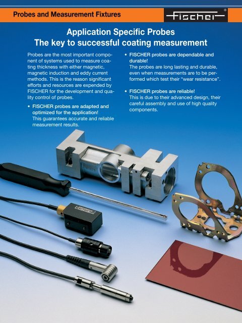
Probes <strong>and</strong> Measurement Fixtures<br />
Application Specific Probes<br />
The key to successful coating measurement<br />
Probes are the most important component<br />
<strong>of</strong> systems used to measure coating<br />
thickness with either magnetic,<br />
magnetic induction <strong>and</strong> eddy current<br />
methods. This is the reason significant<br />
efforts <strong>and</strong> resources are expended by<br />
FISCHER for the development <strong>and</strong> quality<br />
control <strong>of</strong> probes.<br />
• FISCHER probes are adapted <strong>and</strong><br />
optimized for the application!<br />
This guarantees accurate <strong>and</strong> reliable<br />
measurement results.<br />
• FISCHER probes are dependable <strong>and</strong><br />
durable!<br />
The probes are long lasting <strong>and</strong> durable,<br />
even when measurements are to be performed<br />
which test their “wear resistance”.<br />
• FISCHER probes are reliable!<br />
This is due to their advanced design, their<br />
careful assembly <strong>and</strong> use <strong>of</strong> high quality<br />
components.<br />
®
2<br />
Measuring Methods <strong>and</strong> Processing Measuring Signals<br />
This <strong>technical</strong> information material introduces st<strong>and</strong>ard magnetic<br />
probes, magnetic induction probes <strong>and</strong> eddy current<br />
measurement<br />
signal<br />
U = f(Th)<br />
Nickel thickness Th<br />
Magnetic Method<br />
A permanent magnet produces a continuous<br />
magnetic field (DIN EN ISO 2178)<br />
the strength <strong>of</strong> which depends upon the<br />
thickness <strong>of</strong> the coating to be measured<br />
(Ni/Fe), or the distance between probe<br />
<strong>and</strong> substrate (NF/Fe). The strength <strong>of</strong> the<br />
magnetic field is measured with an appropriate<br />
sensor <strong>and</strong> the coating thickness is<br />
calculated from this information.<br />
Signal Processing<br />
The electrical signal transmitted from the<br />
probe is processed by the measuring instrument<br />
<strong>and</strong> digitized. The processed<br />
signal is normalized to st<strong>and</strong>ardize the possible<br />
measuring range <strong>and</strong> to minimize any<br />
disturbing effects. With type E .... series<br />
smart probes this signal is then converted<br />
log d<br />
log d(X n1)<br />
permanent magnet<br />
N<br />
S<br />
non-conducting<br />
non-ferrous<br />
substrate<br />
Hall<br />
effect<br />
sensor<br />
normalized probe signal<br />
linear<br />
measurement<br />
range<br />
logarithmic<br />
measurement<br />
range<br />
Normalization <strong>of</strong> the probe signal is performed<br />
as follows:<br />
X – X o<br />
X n =<br />
X s – X o<br />
The variables are:<br />
X o : probe signal from the uncoated substrate<br />
X s : probe signal from infinitely thick coating<br />
(saturation thickness)<br />
}<br />
probe<br />
exciting current<br />
I~<br />
coating thickness Th<br />
Magnetic Induction Method<br />
The energizing alternating current produces<br />
a low frequency magnetic field (DIN<br />
EN ISO 2178) the strength <strong>of</strong> which depends<br />
upon the distance between the<br />
probe <strong>and</strong> the substrate. The magnetic flux<br />
density is measured by means <strong>of</strong> a pickup<br />
coil. The induced measurement signal obtained<br />
is converted into the coating thickness<br />
value through translation using the<br />
characteristic probe output function.<br />
through a characteristic probe output<br />
function which is stored in the memory<br />
chip <strong>of</strong> the probe connector, into a measurement<br />
value indicative <strong>of</strong> the measured<br />
coating thickness. With other (older)<br />
probes this characteristic function is stored<br />
in the measuring system.<br />
hyperbolicmeasurement<br />
range<br />
s<strong>of</strong>t iron core<br />
iron/steel substrate<br />
0 X n1 1 X n<br />
low frequency<br />
alternating<br />
magnetic field<br />
measurement signal<br />
U = f(d)<br />
X : probe signal from the measured coating<br />
thickness d.<br />
The normalized signal X n therefore is only<br />
able to assume <strong>values</strong> between 0 <strong>and</strong> 1.<br />
X n is then converted over the characteristic<br />
probe output function into the measured<br />
coating thickness value d.<br />
probes to measure coating thickness. The fundamental, physical<br />
pr<strong>inc</strong>iples are explained below.<br />
probe ferrite core<br />
exciting current<br />
I~<br />
measurement signal<br />
U = f(d)<br />
coating thickness Th<br />
non-ferrous substrate<br />
high frequency<br />
alternating<br />
magnetic field<br />
Wirbelströme<br />
Eddy Current Method<br />
The energizing current produces a high<br />
frequency magnetic field (DIN EN ISO 2360)<br />
which induces eddy currents in the substrate<br />
material (or in the coating material to<br />
be measured with the modified test method).<br />
The magnitude <strong>of</strong> the induced eddy currents<br />
depends upon the distance (coating thickness)<br />
between probe <strong>and</strong> substrate. The<br />
measurement signal is then evaluated as a<br />
function <strong>of</strong> the eddy currents produced.<br />
Memory chip to store<br />
information regarding<br />
• the probe (measure-,<br />
ment range, model,<br />
characteristic number)<br />
• the specimen<br />
(geometry, material<br />
characteristics �,�)<br />
Probe<br />
Specimen<br />
Coating<br />
The characteristic probe output function is<br />
stored in the memory chip <strong>of</strong> the probe<br />
connector <strong>and</strong> thus the probe contains all<br />
information required for the measurement.<br />
The operator simply recalls the measurement<br />
application; the system is ready to<br />
measure immediately. Measurements<br />
performed at intermittent time intervals<br />
therefore always start with the same reference<br />
value.
Technical Data <strong>and</strong> Selection <strong>of</strong> Probes<br />
Tables for the selection <strong>of</strong> probes<br />
The solution for many different coating thickness measurements<br />
with the magnetic, magnetic induction or eddy current method<br />
depends upon the selection <strong>of</strong> the „correct“ probe. Often the<br />
measurement accuracy <strong>and</strong> measurement precision can be optimized<br />
by using a more suitable probe.<br />
Explanation to the Technical Data<br />
Measurement Range<br />
The measurement range <strong>of</strong> the probe specifies<br />
the limits <strong>of</strong> the coating thickness that<br />
can be measured.<br />
Measurement Accuracy<br />
(DIN 55350 section 13, paragraph 2.1.1)<br />
The measurement accuracy has been<br />
determined with plastic foils <strong>of</strong> specific<br />
thickness. The specified value us corresponds<br />
to the measured systematic deviation<br />
(bias) between the measured thickness<br />
value <strong>and</strong> true thickness value <strong>of</strong> the<br />
calibration foil.<br />
Example: 50 - 1000 µm: 0.5%<br />
∆<br />
us<br />
This parameter is a quality indicator showing<br />
how good the measurement signal from<br />
the probe has been converted over the<br />
characteristic probe output function stored<br />
in the memory <strong>of</strong> the probe into a corresponding<br />
coating thickness value.<br />
Measurement Precision<br />
(DIN 55350 section 13, paragraph 2.1.2.2)<br />
The value shown represents the measured<br />
st<strong>and</strong>ard deviation, which can be obtained<br />
by replicate measurements on an appropriate<br />
plastic foil.<br />
Test Specimen Geometry<br />
For the above mentioned measurement<br />
methods the geometry <strong>of</strong> the measurement<br />
area influences the measurement value.<br />
The following tables list two <strong>values</strong> for each<br />
geometry dependent factor (except for<br />
substrate thickness).<br />
The upper value indicates the smallest diameter<br />
<strong>of</strong> the object that can be measured,<br />
for which the curvature dependent measurement<br />
bias will not exceed 10% <strong>of</strong> the<br />
true value. Calibration was performed on<br />
a flat surface <strong>of</strong> “infinite” area using the<br />
same substrate material.<br />
The lower value indicates the limiting diameter<br />
at which if exceeded a measurement<br />
is no longer possible due to the geometry<br />
<strong>of</strong> the probe (for example: the probe tip no<br />
longer contacts the surface), or at which<br />
the measurement signal is too small due to<br />
insufficient material volume.<br />
The measurement uncertainly <strong>of</strong> a group<br />
mean measurement is then calculated<br />
according to DIN 1319 section 3 as<br />
follows:<br />
t<br />
u z =<br />
√n . s<br />
For group size n=10 a student’s t value <strong>of</strong><br />
2.5 applies.<br />
Comments<br />
The most important quality attributes <strong>of</strong> a<br />
measurement method are mainly measurement<br />
accuracy, measurement precision<br />
<strong>and</strong> measurement uncertainty.<br />
The measurement uncertainty u (DIN 55350<br />
section 13, par 4.1) is calculated from<br />
u z <strong>and</strong> u s according to:<br />
u= √u 2<br />
z + u 2<br />
s<br />
The measurement methods utilized here<br />
yield different <strong>values</strong> <strong>of</strong> u z <strong>and</strong> u s over the<br />
complete measurement range <strong>of</strong> a probe.<br />
Within the so called linear range <strong>of</strong> the<br />
probe (see graph to the right), their <strong>values</strong><br />
are almost constant. If the same value<br />
applies for the hyperbolic as well as logarithmic<br />
range, the hyperbolic measure-<br />
Measurement point The limit value D indicates the substrate<br />
ø<br />
ø<br />
ø<br />
D<br />
The following tables provide an overview <strong>of</strong> all st<strong>and</strong>ard probes.<br />
The <strong>technical</strong> <strong>data</strong> <strong>and</strong> <strong>values</strong> shown should facilitate selection <strong>of</strong><br />
the probe best suited for your specific application. Explanations<br />
are listed below.<br />
convex curvature<br />
diameter<br />
concave curvature<br />
diameter<br />
diameter <strong>of</strong> the<br />
test area<br />
substrate thickness D<br />
abs. measurement inaccuracy/µm<br />
ment uncertainty is not stated.<br />
The <strong>values</strong> <strong>of</strong> u s <strong>and</strong> u z are listed in the<br />
following tables as either absolute <strong>values</strong><br />
(for example: 1 µm) or as relative <strong>values</strong><br />
referring to the measurement value (for<br />
example: 0.5 %).<br />
The <strong>values</strong> listed represent the optimum<br />
<strong>values</strong> which have been determined with<br />
FISCHER st<strong>and</strong>ards. In many cases<br />
marginal <strong>values</strong> may be obtained due to<br />
less than ideal surface conditions.<br />
FISCHER cannot be held accountable for<br />
marginal <strong>values</strong> obtained from rough<br />
surfaces.<br />
linear<br />
range<br />
logarithmic range<br />
hyperbolic range<br />
Measurement range <strong>of</strong> the probe/µm<br />
thickness below which the measurement<br />
value deviates more than 10% from an<br />
“infinitely“ thick base metal.<br />
The limiting <strong>values</strong> have been determined<br />
with a foil thickness, which produces a<br />
reading which is approximately in the<br />
center <strong>of</strong> the probe measuring range.<br />
With <strong>inc</strong>reasing measured thickness the<br />
10% bias error is obtained with smaller<br />
curvature diameters, <strong>and</strong> respectively<br />
smaller substrate thicknesses.<br />
®<br />
3
4<br />
<strong>Characteristic</strong> <strong>values</strong> <strong>and</strong> <strong>technical</strong> <strong>data</strong> <strong>of</strong> probes for the<br />
Note regarding probe designations:<br />
L: cable length for magnetic induction probes 5 m<br />
<strong>and</strong> for eddy current probes 3 m instead <strong>of</strong> 1.5 m.<br />
F: Measuring element protected against moist,<br />
aggressive media.<br />
T: Intermittent measurements on specimens with<br />
temperatures up to 100 ºC (212 ºF) possible.<br />
* Note: Probe capability (accuracy <strong>and</strong> precision)<br />
tested under controlled conditions.<br />
Description<br />
Order Number<br />
Measurement<br />
range<br />
EGA1.3<br />
602-118<br />
0-1500 µm<br />
0-60 mils<br />
EGAW1.3<br />
602-119<br />
0-1500 µm<br />
0-60 mils<br />
EGAB1.3 601-793<br />
EGAB1.3.L 602-794<br />
EGAB1.3.T 602-359<br />
0-2000 µm<br />
0-80 mils<br />
EGABW1.3 601-964<br />
EGABW1.3.L 602-925<br />
0-2000 µm<br />
0-80 mils<br />
EGABI1.3-150<br />
601-932<br />
0-1000 µm<br />
0-40 mils<br />
EGABI1.3-260<br />
601-961<br />
0-1000 µm<br />
0-40 mils<br />
EGAB1.3-SD<br />
602-107<br />
0-2000 µm<br />
0-80 mils<br />
V1EGA1HR34 602-109<br />
V1EGA1HR34L 602-367<br />
0-1000 µm<br />
0-40 mils<br />
Measurement<br />
accuracy*<br />
u s<br />
Measurement<br />
precision*<br />
s<br />
0-50 µm : 0.25 µm<br />
50-1000 µm : 0.5 %<br />
1000-1500 µm : < 2.5 %<br />
0-50 µm : 0.1 µm<br />
50-1500 µm : 0.2 %<br />
0-50 µm : 0.25 µm<br />
50-1000 µm : 0.5 %<br />
1000-1500 µm : < 2.5 %<br />
0-50 µm : 0.1 µm<br />
50-1500 µm : 0.2 %<br />
0-100 µm : 0.5 µm<br />
100-1000 µm : 0.5 %<br />
1000-2000 µm : < 3 %<br />
0-50 µm : 0.1 µm<br />
50-2000 µm : 0.2 %<br />
0-100 µm : 0.5 µm<br />
100-1000 µm : 0.5 %<br />
1000-2000 µm : < 3 %<br />
0-50 µm : 0.1 µm<br />
50-2000 µm : 0.2 %<br />
0-50 µm : 0.5 µm<br />
50-1000 µm : 1 %<br />
0-50 µm : 0.15 µm<br />
50-1000 µm : 0.3 %<br />
0-50 µm : 0.5 µm<br />
50-1000 µm : 1 %<br />
0-50 µm : 0.15 µm<br />
50-1000 µm : 0.3 %<br />
0-50 µm : 0.5 µm<br />
50-1000 µm : 1 %<br />
1000-2000 µm : < 3 %<br />
0-100 µm : 0.5 µm<br />
100-2000 µm : 0.5 %<br />
0-50 µm : 0.5 µm<br />
50-1000 µm : 1 %<br />
0-100 µm : 0.2 µm<br />
100-1000 µm : 0.2 %<br />
Measurement point<br />
ø<br />
ø<br />
Ø for 10% error<br />
min. Ø<br />
Ø for 10% error<br />
min. Ø<br />
ø : 14 mm (550 mils)<br />
min. ø : 2 mm (80 mils)<br />
ø : 36 mm (1.4“)<br />
min. ø : 10 mm (400 mils)<br />
ø : 14 mm (550 mils)<br />
min. ø : 1 mm (40 mils)<br />
ø : 36 mm (1.4“)<br />
min. ø : 18 mm (700 mils)<br />
ø : 18 mm (700 mils)<br />
min. ø : 2 mm (80 mils)<br />
ø : 35 mm (1.4“)<br />
min. ø : 10 mm (400 mils)<br />
ø : 16 mm (640 mils)<br />
min. ø : 1 mm (40 mils)<br />
ø : 35 mm (1.4“)<br />
min. ø : 18 mm (720 mils)<br />
ø : 16 mm (630 mils)<br />
min. ø : 2 mm (80 mils)<br />
ø : 35 mm (1.4“)<br />
min. ø : 9 mm (350 mils)<br />
ø : 16 mm (630 mils)<br />
min. ø : 2 mm (80 mils)<br />
ø : 35 mm (1.4“)<br />
min. ø : 9 mm (350 mils)<br />
only for flat specimen<br />
only for flat specimen<br />
ø : 18 mm (700 mils)<br />
min. ø : 2 mm (80 mils)<br />
ø : 35 mm (1.4“)<br />
min. ø : 7 mm (280 mils)
magnetic induction measurement method<br />
ø<br />
D<br />
Ø for 10% error<br />
min. Ø<br />
D for 10% error<br />
ø : 8 mm (320 mils)<br />
min. ø : 2 mm (80 mils)<br />
D : 0.2 mm (8 mils)<br />
ø : 8 mm (320 mils)<br />
min. ø : 2 mm (80 mils)<br />
D : 0.2 mm (8 mils)<br />
ø : 8 mm (320 mils)<br />
min. ø : 2 mm (80 mils)<br />
D : 0.2 mm (8 mils)<br />
ø : 8 mm (320 mils)<br />
min. ø : 2 mm (80 mils)<br />
D : 0.2 mm (8 mils)<br />
ø : 8 mm (320 mils)<br />
min. ø : 2 mm (80 mils)<br />
D : 0.2 mm (8 mils)<br />
ø : 8 mm (320 mils)<br />
min. ø : 2 mm (80 mils)<br />
D : 0.2 mm (8 mils)<br />
ø : 8 mm (320 mils)<br />
min. ø : 8 mm (320 mils)<br />
D : 0.2 mm (8 mils)<br />
ø : 6 mm (240 mils)<br />
min. ø : 2 mm (80 mils)<br />
D : 0.2 mm (8 mils)<br />
Probe tip radius<br />
Probe tip material<br />
replaceable probe tip<br />
0.75 mm (30 mils)<br />
Heat treated steel<br />
yes<br />
0.75 mm (30 mils)<br />
Heat treated steel<br />
yes<br />
0.75 mm (30 mils)<br />
PVD coated<br />
yes<br />
0.75 mm (30 mils)<br />
PVD coated<br />
yes<br />
0.75 mm (30 mils)<br />
PVD coated<br />
yes<br />
0.75 mm (30 mils)<br />
PVD coated<br />
yes<br />
flat: ø 8 mm (320 mils)<br />
Polyamide<br />
no<br />
0.8 mm (32 mils)<br />
Tungsten carbide<br />
no<br />
Height<br />
Diameter/width<br />
Length<br />
(see page 24<br />
---<br />
10 mm (0.4“)<br />
110 mm (4.3“)<br />
23 mm (0.9“)<br />
14 mm (0.6“)<br />
72 mm (2.8“)<br />
---<br />
10 mm (0.4“)<br />
110 mm (4.3“<br />
23 mm (0.9“)<br />
14 mm (0.6“)<br />
72 mm (2.8“)<br />
6.5 mm (0.26“)<br />
5.5 mm (0.22“)<br />
320 mm (12.6“)<br />
6.5 mm (0.26“)<br />
5.5 mm (0.22“)<br />
430 mm (17“)<br />
---<br />
18 mm (0.7“)<br />
100 mm (4“)<br />
4.3 mm (0.17“)<br />
4 mm (0.16“)<br />
120 mm (4.7“)<br />
Type <strong>of</strong> probe<br />
Application<br />
Axial single tip probe with spring-loaded measuring system.<br />
Measures nonferrous- <strong>and</strong> nonmetal coatings on steel or iron<br />
substrate (NF, Iso/Fe). Especially well suited for coating thicknesses<br />
<strong>of</strong> ≤ 10 µm. The probe tip is subject to wear on hard <strong>and</strong> abrasive<br />
surfaces. The EGAB1.3 probe should be used for coating<br />
thicknesses > 100 µm.<br />
Single tip right angle probe with spring-loaded measuring system.<br />
Measures nonferrous- <strong>and</strong> nonmetal coatings on steel or iron<br />
substrate (NF, Iso/Fe). Especially well suited for coating thicknesses<br />
<strong>of</strong> ≤ 10 µm (0.4 mil) in pipes, bore holes, recesses, etc.<br />
The probe tip is subject to wear on hard <strong>and</strong> abrasive surfaces.<br />
The EGAWB1.3 probe should be used for coating thicknesses<br />
> 100 µm (4 mils).<br />
Axial single tip probe with spring-loaded measuring system. Measures<br />
nonferrous- <strong>and</strong> nonmetal coatings on steel or iron substrate<br />
(NF, Iso/Fe). Most commonly used probe for electroplated metal<br />
<strong>and</strong> organic coatings. For the measurement <strong>of</strong> nonferrous metal<br />
coatings on steel or iron. Scatter <strong>of</strong> the measuring <strong>values</strong> on rough<br />
(for example: grit blasted) surfaces is however relatively high.<br />
Double pole probes should be used in such instances if the geometry<br />
<strong>of</strong> the parts permits the use <strong>of</strong> this type <strong>of</strong> probe.<br />
Single tip right angle probe with spring-loaded measuring system.<br />
Measures nonferrous- <strong>and</strong> nonmetal coatings on steel or iron<br />
substrate (NF, Iso/Fe). Most commonly used probe for electroplated<br />
metal <strong>and</strong> organic coatings in pipes, bore holes, recesses,<br />
etc. Scatter <strong>of</strong> the measuring <strong>values</strong> on rough (for example: grit<br />
blasted) surfaces is however relatively high. Double pole probes<br />
should be used in such instances if the geometry <strong>of</strong> the parts<br />
permits the use <strong>of</strong> this type <strong>of</strong> probe.<br />
Single pole probe for inside measurement applications with springloaded<br />
measuring system. Measures nonferrous- <strong>and</strong> nonmetal<br />
coatings on steel or iron substrate (NF, Iso/Fe). Suitable for measurements<br />
in bore holes, pipes or grooves. To obtain the smallest<br />
possible measurement uncertainty, externally triggered measurement<br />
acquisition should be used when measuring small inside diameters<br />
to prevent measurement errors. Smallest permissible inside<br />
diameter: 9 mm (0.36“). Maximum insertion depth: 150 mm (6“).<br />
Single pole probe for inside measurement applications with springloaded<br />
measuring system. Measures nonferrous- <strong>and</strong> nonmetal<br />
coatings on steel or iron substrate (NF, Iso/Fe). Suitable for measurements<br />
in bore holes, pipes or grooves. To obtain the smallest<br />
possible measurement uncertainty, externally triggered measurement<br />
acquisition should be used when measuring small inside diameters<br />
to prevent measurement errors. Smallest permissible inside<br />
diameter: 9 mm (0.36“). Maximum insertion depth: 260 mm (10“).<br />
Axial single tip probe with spring-loaded measuring system.<br />
Measures nonferrous- <strong>and</strong> nonmetal coatings on steel or iron<br />
substrate (NF, Iso/Fe). The flat surface probe tip is especially suited<br />
for s<strong>of</strong>t coatings (screen printing material, s<strong>of</strong>t plastic material,<br />
etc.). For the measurement <strong>of</strong> nonferrous metal coatings on steel<br />
or iron. The surface to be measured has to be completely clean.<br />
Any foreign matter or dirt particles on the test surface produces<br />
measurement errors.<br />
Single tip probe for inside measurement applications with fixed measurement<br />
system. Measures nonferrous- <strong>and</strong> nonmetal coatings on<br />
steel or iron substrate (NF, Iso/Fe). Suitable for measurements in<br />
bore holes, pipes or grooves. To obtain the smallest possible measurement<br />
uncertainty, externally triggered measurement acquisition<br />
should be used when measuring small inside diameters to prevent<br />
measurement errors. Smallest permissible inside diameter: 7 mm<br />
(0.28“). Maximum insertion depth: 60 mm (2.4“).<br />
®<br />
5
6<br />
<strong>Characteristic</strong> <strong>values</strong> <strong>and</strong> <strong>technical</strong> <strong>data</strong> <strong>of</strong> probes for the<br />
Note regarding probe designations:<br />
L: cable length for magnetic induction probes 5 m<br />
<strong>and</strong> for eddy current probes 3 m instead <strong>of</strong> 1.5 m.<br />
F: Measuring element protected against moist,<br />
aggressive media.<br />
T: Intermittent measurements on specimens with<br />
temperatures up to 100 ºC (212 ºF) possible.<br />
* Note: Probe capability (accuracy <strong>and</strong> precision)<br />
tested under controlled conditions.<br />
Description<br />
Order Number<br />
Measurement<br />
range<br />
EGA2H 602-121<br />
EGA2HF 602-754<br />
0-1500 µm<br />
0-60 mils<br />
EGAW2H<br />
602-122<br />
0-1500 µm<br />
0-60 mils<br />
EGB2<br />
602-023<br />
0-5 mm<br />
0-200 mils<br />
EGBW2<br />
602-024<br />
0-5 mm<br />
0-200 mils<br />
EK4<br />
602-123<br />
0-2000 µm<br />
0-80 mils<br />
EKB4<br />
602-108<br />
0-2000 µm<br />
0-80 mils<br />
V1EKB4<br />
602-126<br />
0-2000 µm<br />
0-80 mils<br />
V7EK4 602-582<br />
V7EK4L 602-605<br />
0-2000 µm<br />
0-80 mils<br />
Measurement<br />
accuracy*<br />
u s<br />
Measurement<br />
precision*<br />
s<br />
0-50 µm : 0.25 µm<br />
50-500 µm : 0.5 %<br />
500-1500 µm : < 1 %<br />
0-50 µm : 0.15 µm<br />
50-1500 µm : 0.3 %<br />
0-50 µm : 0.25 µm<br />
50-500 µm : 0.5 %<br />
500-1500 µm : < 1 %<br />
0-50 µm : 0.15 µm<br />
50-1500 µm : 0.3 %<br />
0-0,2 mm : 0.002 mm<br />
0,2-3 mm : 1 %<br />
3-5 mm : < 5 %<br />
0-0,2 mm : 0.0005 mm<br />
0,2-5 mm : 0.3 %<br />
0-0,2 mm : 0.002 mm<br />
0,2-3 mm : 1 %<br />
3-5 mm : < 5 %<br />
0-0,2 mm : 0.0005 mm<br />
0,2-5 mm : 0.3 %<br />
0-100 µm : 1 µm<br />
100-2000 µm : 1 %<br />
0-25 µm : 0.1 µm<br />
25-2000 µm : 0.4 %<br />
0-100 µm : 0.5 µm<br />
100-2000 µm : 0.5 %<br />
0-50 µm : 0.15 µm<br />
50-2000 µm : 0.3 %<br />
0-100 µm : 0.5 µm<br />
100-2000 µm : 0.5 %<br />
0-50 µm : 0.15 µm<br />
50-2000 µm : 0.3 %<br />
0-100 µm : 1.5 µm<br />
100-2000 µm : 1.5 %<br />
0-25 µm : 0.1 µm<br />
25-2000 µm : 0.4 %<br />
Measurement point<br />
ø<br />
ø<br />
Ø for 10% error<br />
min. Ø<br />
Ø for 10% error<br />
min. Ø<br />
ø : 25 mm (990 mils)<br />
min. ø : 2 mm (80 mils)<br />
ø : 34 mm (1.3“)<br />
min. ø : 22 mm (870 mils)<br />
ø : 25 mm (990 mils)<br />
min. ø : 2 mm (80 mils)<br />
ø : 34 mm (1.3“)<br />
min. ø : 18 mm (700 mils)<br />
ø : 30 mm (1.2“)<br />
min. ø : 2 mm (80 mils)<br />
ø : 40 mm (1.6“)<br />
min. ø : 9 mm (350 mils)<br />
ø : 30 mm (1.2“)<br />
min. ø : 2 mm (80 mils)<br />
ø : 40 mm (1.6“)<br />
min. ø : 18 mm (700 mils)<br />
ø : 22 mm (870 mils)<br />
min. ø : 2 mm (80 mils)<br />
ø : 38 mm (1.5“)<br />
min. ø : 13 mm (510 mils)<br />
ø : 20 mm (800 mils)<br />
min. ø : 2 mm (80 mils)<br />
ø : 38 mm (1.5“)<br />
min. ø : 13 mm (510 mils)<br />
ø : 20 mm (800 mils)<br />
min. ø : 2 mm (80 mils)<br />
ø : 38 mm (1.5“)<br />
min. ø : 20 mm (800 mils)<br />
ø : 22 mm (870 mils)<br />
min. ø : 2 mm (80 mils)<br />
ø : 38 mm (1.5“)<br />
min. ø : 20 mm (800 mils)
magnetic induction measurement method<br />
ø<br />
D<br />
Ø for 10% error<br />
min. Ø<br />
D for 10% error<br />
ø : 15 mm (590 mils)<br />
min. ø : 2 mm (80 mils)<br />
ø : 15 mm (590 mils)<br />
min. ø : 2 mm (80 mils)<br />
ø : 15 mm (590 mils)<br />
min. ø : 2 mm (80 mils)<br />
D : 0.4 mm (16 mils)<br />
ø : 12 mm (470 mils)<br />
min. ø : 2 mm (80 mils)<br />
D : 0.25 mm (10 mils)<br />
ø : 12 mm (470 mils)<br />
min. ø : 2 mm (80 mils)<br />
D : 0.25 mm (10 mils)<br />
ø : 30 mm (1.2“)<br />
min. ø : 15 mm (590 mils)<br />
D : 0.4 mm (16 mils)<br />
ø : 30 mm (1.2“)<br />
min. ø : 15 mm (590 mils)<br />
D : 0.4 mm (16 mils)<br />
ø : 30 mm (1.2“)<br />
min. ø : 15 mm (590 mils)<br />
D : 0.4 mm (16 mils)<br />
ø : 30 mm (1.2“)<br />
min. ø : 15 mm (590 mils)<br />
D : 0.4 mm (16 mils)<br />
Probe tip radius<br />
Probe tip material<br />
replaceable probe tip<br />
2.25 mm (88 mils)<br />
Tungsten carbide<br />
yes<br />
2.25 mm (88 mils)<br />
Tungsten carbide<br />
yes<br />
1.0 mm (40 mils)<br />
PVD coated<br />
yes<br />
1.0 mm (40 mils)<br />
PVD coated<br />
yes<br />
1.25 mm (49 mils)<br />
Heat treated steel<br />
yes<br />
1.25 mm (49 mils)<br />
PVD coated<br />
yes<br />
1.25 mm (49 mils)<br />
PVD coated<br />
yes<br />
1.25 mm (49 mils)<br />
Heat treated steel<br />
yes<br />
Height<br />
Diameter/width<br />
Length<br />
(see page 24)<br />
---<br />
13 mm (0.5“)<br />
80 mm (3.2“)<br />
23 mm (0.9“)<br />
14 mm (0.6“)<br />
72 mm (2.8“)<br />
---<br />
10 mm (0.4“)<br />
110 mm (4.3“)<br />
23 mm (0.9“)<br />
14 mm (0.6“)<br />
72 mm (2.8“)<br />
21 mm (0.8“)<br />
12 mm (0.5“)<br />
18 mm (0.7“)<br />
21 mm (0.8“)<br />
12 mm (0.5“)<br />
18 mm (0.7“)<br />
---<br />
8.5 mm (0.3“)<br />
300 mm (11.8“)<br />
---<br />
20 mm (0.8“)<br />
70 mm (2.8“)<br />
Type <strong>of</strong> probe<br />
Application<br />
Axial single tip probe with spring-loaded measuring system.<br />
Measures nonferrous- <strong>and</strong> nonmetal coatings on steel or iron<br />
substrate (NF, Iso/Fe). Due to the larger probe tip diameter better<br />
suited for rough surfaces than the EGAB1.3 probe.<br />
Axial single tip probe with spring-loaded measuring system.<br />
Measures nonferrous- <strong>and</strong> nonmetal coatings on steel or iron<br />
substrate (NF, Iso/Fe). Due to the larger probe tip diameter better<br />
suited for rough surfaces than the EGABW1.3 probe.<br />
Axial single tip probe with spring-loaded measuring system.<br />
Measures nonferrous- <strong>and</strong> nonmetal coatings on steel or iron<br />
substrate (NF, Iso/Fe). Has the largest measurement range <strong>of</strong><br />
all single tip probes. Due to unshielded magnetic field larger<br />
geometric influence, however smaller tilting effect.<br />
Single tip angle probe with spring-loaded measuring system.<br />
Measures nonferrous- <strong>and</strong> nonmetal coatings on steel or iron<br />
substrate (NF, Iso/Fe). Same as EGB2 probe, however preferably<br />
used for measurements in pipes, bore holes or recesses.<br />
Double pole probe for angular measurements with fixed measurement<br />
system. Measures nonferrous- <strong>and</strong> nonmetal coatings on<br />
steel or iron substrate (NF, Iso/Fe). Double pole probe producing<br />
the lowest possible measurement uncertainty. The uncoated<br />
probe tips make this probe especially suited for thin coatings (for<br />
example: lubricant <strong>and</strong> phosphate coatings). Greater measuring<br />
precision on rough surfaces than single tip probes, however faster<br />
probe tip wear than with EKB4 probe.<br />
Double pole probe for angular measurements with fixed measurement<br />
system. Measures nonferrous- <strong>and</strong> nonmetal coatings<br />
on steel or iron substrate (NF, Iso/Fe). Well suited for thin coatings.<br />
Higher measurement precision on rough surfaces than single<br />
pole probes.<br />
Double pole probe for inside measurements with spring-loaded<br />
measuring system. Measures nonferrous- <strong>and</strong> nonmetal coatings<br />
on steel or iron substrate (NF, Iso/Fe). Suitable for measurement in<br />
bore holes, pipes or grooves. Greater measuring precision on<br />
rough surfaces than with EGABI1.3 -150 (260) probe.<br />
Smallest permissible inside diameter: 8.5 mm (0.34“)<br />
Maximum insertion depth: 185 mm (7.4“)<br />
Axial double-tip measurement probe with spring-loaded measuring<br />
element. Measures nonferrous <strong>and</strong> nonmetal coatings on steel or<br />
iron (NE, Iso/Fe). Especially well suited for thin layers (phosphorous<br />
coatings) because <strong>of</strong> uncoated probe tips. Higher repeatability<br />
than single tip probes when measuring rough surfaces. Spring<br />
loaded measuring system allows exact positioning <strong>and</strong> constant<br />
pressure force, which is advantageous for measuring weak<br />
coatings.<br />
®<br />
7
8<br />
<strong>Characteristic</strong> <strong>values</strong> <strong>and</strong> <strong>technical</strong> <strong>data</strong> <strong>of</strong> probes for the<br />
Note regarding probe designations:<br />
L: cable length for magnetic induction probes 5 m<br />
<strong>and</strong> for eddy current probes 3 m instead <strong>of</strong> 1.5 m.<br />
F: Measuring element protected against moist,<br />
aggressive media.<br />
T: Intermittent measurements on specimens with<br />
temperatures up to 100 ºC (212 ºF) possible.<br />
* Note: Probe capability (accuracy <strong>and</strong> precision)<br />
tested under controlled conditions.<br />
Description<br />
Order Number<br />
Measurement<br />
range<br />
V7EKB4<br />
V7EKB4L<br />
EKB10<br />
602-225<br />
0-8 mm<br />
0-320 mils<br />
EKB10-OD<br />
EKB10L-OD<br />
EKB25<br />
EKB25L<br />
0-2000 µm<br />
0-80 mils<br />
0-8 mm<br />
0-320 mils<br />
V1EKB10<br />
602-676<br />
0-8 mm<br />
0-320 mils<br />
0-15 mm<br />
0-590 mils<br />
602-583<br />
602-606<br />
602-165<br />
602-760<br />
601-952<br />
602-913<br />
Measurement<br />
accuracy*<br />
u s<br />
Measurement<br />
precision*<br />
s<br />
0-100 µm : 1 µm<br />
100-2000 µm : 1 %<br />
0-50 µm : 0.15 µm<br />
50-2000 µm : 0.3 %<br />
0-0.5 mm : 0.005 mm<br />
0.5-8 mm : 1 %<br />
0-0.5 mm : 0.0025 mm<br />
0.5-8 mm : 0.5 %<br />
0-0.5 mm : 0.005 mm<br />
0.5-8 mm : 1 %<br />
0-0.5 mm : 0.0015 mm<br />
0.5-8 mm : 0.3 %<br />
0-0.5 mm : 0.01 mm<br />
0.5-8 mm : 2 %<br />
0-0.5 mm : 0.0025 mm<br />
0.5-8 mm : 0.5 %<br />
0-1 mm : 0.02 mm<br />
1-7 mm : 2 %<br />
7-15 mm : < 5 %<br />
0-0.5 mm : 0.01 mm<br />
0.5-15 mm : 2 %<br />
Measurement point<br />
ø<br />
ø<br />
Ø for 10% error<br />
min. Ø<br />
Ø for 10% error<br />
min. Ø<br />
ø : 20 mm (800 mils)<br />
min. ø : 2 mm ( 80 mils)<br />
ø : 38 mm (1.5“)<br />
min. ø : 20 mm ( 800 mils)<br />
ø : 50 mm (2“)<br />
min. ø : 2 mm (80 mils)<br />
ø : 75 mm (3“)<br />
min. ø : 24 mm (950 mils)<br />
ø : 50 mm (2“)<br />
min. ø : 2 mm (80 mils)<br />
∞<br />
∞<br />
ø : 50 mm (2“)<br />
min. ø : 2 mm (80 mils)<br />
ø : 75 mm (3“)<br />
min. ø : 24 mm (950 mils)<br />
ø : 60 mm (2.4“)<br />
min. ø : 10 mm (400 mils)<br />
ø : 85 mm (3.3“)<br />
min. ø : 20 mm (800 mils)<br />
Note concerning the application <strong>of</strong> probes using the magnetic induction measurement method:<br />
Please consult with the manufacturer before measuring electrically conducting coatings with thicknesses > 500 µm (20 mils).
magnetic induction measurement method<br />
ø<br />
D<br />
Ø for 10% error<br />
min. Ø<br />
D for 10% error<br />
ø : 30 mm (1.2“)<br />
min. ø : 15 mm (590 mils)<br />
D : 0.4 mm (16 mils)<br />
ø : 30 mm (1.2“)<br />
min. ø : 20 mm (800 mils)<br />
D : 0.5 mm (20 mils)<br />
ø : 30 mm (1.2“)<br />
min. ø : 38 mm (1.5“)<br />
D : 0.5 mm (20 mils)<br />
ø : 30 mm (1.2“)<br />
min. ø : 20 mm (800 mils)<br />
D : 0.5 mm (20 mils)<br />
ø : 50 mm (2“)<br />
min. ø : 40 mm (1.6“)<br />
D : 0.7 mm (28 mils)<br />
Probe tip radius<br />
Probe tip material<br />
replaceable probe tip<br />
1.25 mm (49 mils)<br />
PVD coated<br />
yes<br />
1.5 mm (60 mils)<br />
PVD coated<br />
yes<br />
flat: 34 x 24 mm<br />
(1300 x 950 mils)<br />
Polyamide<br />
no<br />
1.5 mm (60 mils)<br />
PVD coated<br />
yes<br />
1.5 mm (60 mils)<br />
PVD coated<br />
yes<br />
Height<br />
Diameter/width<br />
Length<br />
(see page 24)<br />
---<br />
20 mm (0.8“)<br />
70 mm (2.8“)<br />
27 mm (1.1“)<br />
14 mm (0.5“)<br />
50 mm (2“)<br />
26 mm (1.0“)<br />
24 mm (1.0“)<br />
53 mm (2.1“)<br />
---<br />
13 mm (0.5“)<br />
380 mm (15“)<br />
33 mm (1.3“)<br />
20 mm (0.8“)<br />
65 mm (2.6“)<br />
Type <strong>of</strong> probe<br />
Application<br />
Axial double tip measurement probe with spring-loaded measuring<br />
system. Measurement <strong>of</strong> nonferrous- <strong>and</strong> nonmetal coatings on<br />
steel or iron substrate (NF, Iso/Fe).<br />
Higher measurement precision on rough surfaces than single tip<br />
probes. Spring-loaded measuring system provides better<br />
positioning <strong>and</strong> constant pressure force (advantageous for<br />
measuring s<strong>of</strong>t coatings).<br />
Double pole probe for angular measurements with fixed<br />
measurement system.<br />
Especially well suited for thick coatings. Greater measuring<br />
precision on rough surfaces than single pole probes.<br />
Double pole probe for angular measurements with fixed<br />
measurement system.<br />
The large flat contact surface is especially well suited for thick <strong>and</strong><br />
compressible s<strong>of</strong>t coatings (for example rubber sheeting for <strong>of</strong>fset<br />
printing).<br />
Double pole probe for angular measurements with<br />
spring-loaded measuring system.<br />
Suitable for thick coatings in bore holes, pipes, or recesses.<br />
Greater measuring precision on rough surfaces than with single<br />
pole probes. Externally triggered measurement acquisition should<br />
be used with small inside diameters to prevent measurement<br />
errors.<br />
Smallest permissible inside diameter: 13 mm (0.5“)<br />
Maximum insertion depth : 260 mm (10“)<br />
Double pole probe for angular measurements with fixed<br />
measurement system.<br />
Especially suited for thick, nonmetallic coatings.<br />
®<br />
9
10<br />
<strong>Characteristic</strong> <strong>values</strong> <strong>and</strong> <strong>technical</strong> <strong>data</strong> <strong>of</strong> probes for the<br />
Note regarding probe designations:<br />
L: cable length for magnetic induction probes 5 m<br />
<strong>and</strong> for eddy current probes 3 m instead <strong>of</strong> 1.5 m.<br />
F: Measuring element protected against moist,<br />
aggressive media.<br />
T: Intermittent measurements on specimens with<br />
temperatures up to 100 ºC (212 ºF) possible.<br />
* Note: Probe capability (accuracy <strong>and</strong> precision)<br />
tested under controlled conditions.<br />
Description<br />
Order Number<br />
Measurement<br />
range<br />
EK50 602-127<br />
EK50L 602-923<br />
0-30 mm<br />
0-1200 mils<br />
EGA06H 602-936<br />
EGA06H-L 602-626<br />
0-700 µm<br />
0-28 mils<br />
EGA06H-MC<br />
603-092<br />
0-700 µm<br />
0-28 mils<br />
V2EGA06H<br />
603-112<br />
0-700 µm<br />
0-28 mils<br />
Measurement<br />
accuracy*<br />
u s<br />
Measurement<br />
precision*<br />
s<br />
0-1 mm : 0.05 mm<br />
1-10 mm : 5 %<br />
10-30 mm : < 7 %<br />
0-1 mm : 0.02 mm<br />
1-30 mm : 2%<br />
0-50 µm : 0.3 µm<br />
50-700 µm : < 2 %<br />
0-50 µm : 0.1 µm<br />
50-700 µm : < 0.3 %<br />
0-70 µm : 0.3 µm<br />
70-700 µm : < 2 %<br />
0-70 µm : 0.08 µm<br />
70-700 µm : < 0.08 %<br />
0-50 µm : 0.3 µm<br />
50-700 µm : < 2 %<br />
0-50 µm : 0.1 µm<br />
50-700 µm : < 0.3 %<br />
Measurement point<br />
ø<br />
ø<br />
Ø for 10% error<br />
min. Ø<br />
Ø for 10% error<br />
min. Ø<br />
ø : 100 mm (4“)<br />
min. ø : 10 mm (400 mils)<br />
ø : 140 mm (5.5“)<br />
min. ø : 14 mm (550 mils)<br />
ø : 18 mm (720 mils)<br />
min. ø : 1 mm ( 40 mils)<br />
ø : 30 mm (1.2“)<br />
min. ø : 20 mm (800 mils)<br />
ø : 18 mm (720 mils)<br />
min. ø : 1 mm ( 40 mils)<br />
ø : 30 mm (1.2“)<br />
min. ø : 20 mm (800 mils)<br />
ø : 18 mm (720 mils)<br />
min. ø : 1 mm ( 40 mils)<br />
---
eddy current measuring method<br />
ø<br />
D<br />
Ø for 10% error<br />
min. Ø<br />
D for 10% error<br />
ø : 84 mm (3.3“)<br />
min. ø : 70 mm (2.8“)<br />
D : 1.2 mm (47 mils)<br />
ø : 5 mm (200 mils)<br />
min. ø : 2 mm (80 mils)<br />
D : 0.25 mm (10 mils)<br />
ø : 5 mm (200 mils)<br />
min. ø : 2 mm (80 mils)<br />
D : 0.25 mm (10 mils)<br />
ø : 5 mm (200 mils)<br />
min. ø : 2 mm (80 mils)<br />
D : 0.25 mm (10 mils)<br />
Probe tip radius<br />
Probe tip material<br />
replaceable probe tip<br />
2.5 mm (98 mils)<br />
Heat treated steel<br />
yes<br />
0.3 mm (12 mils)<br />
Tungsten carbide<br />
no<br />
0.3 mm (12 mils)<br />
Tungsten carbide<br />
no<br />
0.3 mm (12 mils)<br />
Tungsten carbide<br />
no<br />
Height<br />
Diameter/width<br />
Length<br />
(see page 24)<br />
33 mm (1.3“)<br />
20 mm (0.8“)<br />
95 mm (3.7“)<br />
110 mm (4.4“)<br />
13 mm (0.52“)<br />
---<br />
110 mm (4.4“)<br />
13 mm (0.52“)<br />
---<br />
---<br />
10 mm (0.4“)<br />
110 mm (4.4“)<br />
Type <strong>of</strong> probe<br />
Application<br />
Double pole probe for angular measurements with fixed<br />
measurement system.<br />
Especially suited for very thick, nonmetallic coatings.<br />
For austenitic stainless steel coatings smaller measurement errors<br />
due to ferromagnetic delta ferrite content than with all other types<br />
<strong>of</strong> probes.<br />
Axial single tip measurement probe with spring-loaded measuring<br />
system. Measures electrically nonconducting or nonferrous<br />
coatings on steel or iron (NF/Fe).<br />
Mechanical design especially suited for installation in customerspecific<br />
probe fixtures or guide devices for precise probe<br />
positioning.<br />
Axial single tip measurement probe with spring-loaded measuringt<br />
system. Measures electrically nonconducting or nonferrous<br />
coatings on steel or iron (NF/Fe).<br />
Mechanical design especially suited for installation in customerspecific<br />
probe fixtures or guide devices for precise probe<br />
positioning.<br />
Measures electrically nonconducting or nonferrous metal<br />
coatings on steel or iron (NF/Fe). Measuring element same as<br />
with EGA06H probe.<br />
Especially well suited for the integration in automated<br />
measurement systems. No measurement tip wear even after<br />
several million measurement cycles when used properly.<br />
Suited for cylindrical specimen with diameter range 8 to 25 mm.<br />
(0.32“ to 1“). Other diameters on request.<br />
®<br />
11
12<br />
<strong>Characteristic</strong> <strong>values</strong> <strong>and</strong> <strong>technical</strong> <strong>data</strong> <strong>of</strong> probes for the<br />
Note regarding probe designations:<br />
L: cable length for magnetic induction probes 5 m<br />
<strong>and</strong> for eddy current probes 3 m instead <strong>of</strong> 1.5 m.<br />
F: Measuring element protected against moist,<br />
aggressive media.<br />
T: Intermittent measurements on specimens with<br />
temperatures up to 100 ºC (212 ºF) possible.<br />
* Note: Probe capability (accuracy <strong>and</strong> precision)<br />
tested under controlled conditions.<br />
Description<br />
Order Number<br />
Measurement<br />
range<br />
ETA3.3H<br />
ETA3.3HL<br />
EAW3.3<br />
EAW3.3L<br />
EA30<br />
EA30L<br />
0-1200 µm<br />
0-45 mils<br />
ETA3.3<br />
601-797<br />
0-1200 µm<br />
0-45 mils<br />
ETA3.3FG<br />
602-623<br />
0-1200 µm<br />
0-45 mils<br />
ETA3.3-5.6<br />
602-645<br />
0-1200 µm<br />
0-45 mils<br />
0-1200 µm<br />
0-45 mils<br />
EAI3.3-150<br />
602-026<br />
0-800 µm<br />
0-32 mils<br />
EA9<br />
601-965<br />
0-3.5 mm<br />
0-140 mils<br />
0-20 mm<br />
0-800 mils<br />
602-128<br />
602-799<br />
602-025<br />
602-922<br />
602-027<br />
602-633<br />
Measurement<br />
accuracy*<br />
u s<br />
Measurement<br />
precision*<br />
s<br />
0-50 µm : 0.25 µm<br />
50-800 µm : 0.5 %<br />
800-1200 µm : < 2 %<br />
0-50 µm : 0.15 µm<br />
50-1200 µm : 0.3 %<br />
0-100 µm : 0.5 µm<br />
100-800 µm : 0.5 %<br />
800-1200 µm : < 3 %<br />
0-100 µm : 0.2 µm<br />
100-1200 µm : 0.2 %<br />
0-50 µm : 0.25 µm<br />
50-1200 µm : 0.5 %<br />
0-50 µm : 0.1 µm<br />
50-1200 µm : 0.2 %<br />
0-100 µm : 0.5 µm<br />
100-800 µm : 0.5 %<br />
800-1200 µm : < 3 %<br />
0-100 µm : 0.2 µm<br />
100-1200 µm : 0.2 %<br />
0-50 µm : 0.75 µm<br />
50-1200 µm : 1.5 %<br />
0-50 µm : 0.25 µm<br />
50-1200 µm : 0.5 %<br />
0-200 µm : 1 µm<br />
200-800 µm : 0.5 %<br />
0-100 µm : 0.3 µm<br />
100-800 µm : 0.3 %<br />
0-0.25 mm : 0.005 mm<br />
0.25-2.5 mm : 2 %<br />
2.5-3.5 mm : < 3.5 %<br />
0-1 mm : 0.002 mm<br />
1-3.5 mm : 0.2 %<br />
0-2 mm : 0.05 mm<br />
2-20 mm : 2.5 %<br />
0-1 mm : 0.002 mm<br />
1-20 mm : 0.2 %<br />
Measurement point<br />
ø<br />
ø<br />
Ø for 10% error<br />
min. Ø<br />
Ø for 10% error<br />
min. Ø<br />
ø : 50 mm (2“)<br />
min. ø : 2 mm (80 mils)<br />
ø : 50 mm (2“)<br />
min. ø : 30 mm (1.2“)<br />
ø : 50 mm (2“)<br />
min. ø : 2 mm (80 mils)<br />
ø : 55 mm (2.2“)<br />
min. ø : 30 mm (1.2“)<br />
ø : 50 mm (2“)<br />
min. ø : 2 mm (80 mils)<br />
∞<br />
∞<br />
ø : 50 mm (2“)<br />
min. ø : 2 mm (80 mils)<br />
ø : 50 mm (2“)<br />
min. ø : 30 mm (1.2“)<br />
ø : 50 mm (2“)<br />
min. ø : 2 mm (80 mils)<br />
ø : 50 mm (2“)<br />
min. ø : 34 mm (1.6“)<br />
ø : 60 mm (2.4“)<br />
min. ø : 2 mm (80 mils)<br />
ø : 55 mm (2.2“)<br />
min. ø : 9 mm (350 mils)<br />
ø : 160 mm (6.3“)<br />
min. ø : 2 mm (80 mils)<br />
ø : 160 mm (6.3“)<br />
min. ø : 40 mm (1.6“)<br />
ø : 1200 mm (47“)<br />
min. ø : 200 mm (7.9“)<br />
∞<br />
∞
eddy current measuring method<br />
ø<br />
D<br />
Ø for 10% error<br />
min. Ø<br />
D for 10% error<br />
ø : 4 mm (160 mils)<br />
min. ø : 2 mm (80 mils)<br />
D : 0.09 mm (3.5 mils)<br />
ø : 4 mm (160 mils)<br />
min. ø : 2 mm (80 mils)<br />
D : 0.09 mm (3.5 mils)<br />
ø : 15 mm (590 mils)<br />
min. ø : 7 mm (280 mils)<br />
D : 0.09 mm (3.5 mils)<br />
ø : 4 mm (160 mils)<br />
min. ø : 2 mm (80 mils)<br />
D : 0.09 mm (3.5 mils)<br />
ø : 4 mm (160 mils)<br />
min. ø : 2 mm (80 mils)<br />
D : 0.09 mm (3.5 mils)<br />
ø : 4 mm (160 mils)<br />
min. ø : 2 mm (80 mils)<br />
D : 0.09 mm (3.5 mils)<br />
ø : 4 mm (160 mils)<br />
min. ø : 2 mm (80 mils)<br />
D : 0.09 mm (3.5 mils)<br />
ø : 42 mm (1.6“)<br />
min. ø : 34 mm (1.3“)<br />
D : 0.09 mm (3.5 mils)<br />
Probe tip radius<br />
Probe tip material<br />
replaceable probe tip<br />
1.2 mm (47 mils)<br />
Tungsten carbide<br />
yes<br />
1.2 mm (47 mils)<br />
Jewel tip<br />
yes<br />
2.5 mm (98 mils)<br />
Polyamide<br />
yes<br />
2.8 mm (110 mils)<br />
Jewel tip<br />
yes<br />
1.2 mm (47 mils)<br />
Jewel tip<br />
yes<br />
1.2 mm (47 mils)<br />
Jewel tip<br />
yes<br />
8 mm (320 mils)<br />
Heat treated steel<br />
no<br />
flat: ø 34 mm (1.3“)<br />
Polyamide<br />
no<br />
Height<br />
Diameter/width<br />
Length<br />
(see page 24)<br />
---<br />
18 mm (0.7“)<br />
70 mm (2.8“)<br />
---<br />
18 mm (0.7“)<br />
70 mm (2.8“)<br />
---<br />
18 mm (0.7“)<br />
70 mm (2.8“)<br />
---<br />
18 mm (0.7“)<br />
70 mm (2.8“)<br />
23 mm (0.9“)<br />
14 mm (0.6“)<br />
72 mm (2.8“)<br />
6.5 mm (0.26“)<br />
5.5 mm (0.22“)<br />
320 mm (12.6“)<br />
23 mm (0.9“)<br />
14 mm (0.6“)<br />
72 mm (2.8“)<br />
43 mm<br />
(1.7“)<br />
34 mm (1.3“)<br />
60 mm (2.4“)<br />
Type <strong>of</strong> probe<br />
Application<br />
Axial single tip probe with spring-loaded measuring system.<br />
Measurement <strong>of</strong> nonconductive coatings on nonferromagnetic<br />
substrate (Iso/NF).<br />
Highly impact- <strong>and</strong> shatter resistant probe tip.<br />
St<strong>and</strong>ard probe for paint <strong>and</strong> plastic coatings. Should not be used<br />
when surfaces exhibit a damp condition (acidic contamination <strong>of</strong><br />
test surface).<br />
Axial single tip probe with spring-loaded measuring system.<br />
Measurement <strong>of</strong> nonconductive coatings on nonferromagnetic<br />
substrate (Iso/NF).<br />
St<strong>and</strong>ard probe for paint <strong>and</strong> plastic coatings, as well as for<br />
anodized coatings. Can possibly also be used when surfaces<br />
exhibit a damp condition (acidic contamination <strong>of</strong> test surface).<br />
Smaller tilting effect than with ETA3.3F probe.<br />
Axial single tip probe with spring-loaded measuring system.<br />
Measurement <strong>of</strong> nonconductive coatings on nonferromagnetic<br />
substrate (Iso/NF).<br />
Especially suited for anodized coatings when surfaces exhibit a<br />
wet (acidic) contamination <strong>of</strong> the test surface. Larger tilting effect<br />
than with ETA3.3 probe.<br />
Axial single tip probe with spring-loaded measuring system.<br />
Measurement <strong>of</strong> nonconductive coatings on nonferromagnetic<br />
substrate (Iso/NF).<br />
Due to the larger radius <strong>of</strong> the probe tip lower measurement<br />
scatter on rough surfaces than with ETA3.3 probe.<br />
Single tip angle probe with spring-loaded measuring system.<br />
Measurement <strong>of</strong> nonconductive coatings on nonferromagnetic<br />
substrate (Iso/NF).<br />
Suitable for measurements on flat objects or in pipes, bore holes<br />
<strong>and</strong> recesses. Can also be used when surfaces exhibit a damp<br />
condition (acidic contamination <strong>of</strong> test surface).<br />
Single tip angle probe with spring-loaded measuring system.<br />
Measurement <strong>of</strong> nonconductive coatings on nonferromagnetic<br />
substrate (Iso/NF).<br />
Suitable for measurements in pipes, bore holes <strong>and</strong> recesses, etc.<br />
Can possibly also be used when surfaces exhibit a wet condition<br />
(acidic contamination <strong>of</strong> test surface). To avoid positioning errors<br />
externally triggered measurement acquisition should be used.<br />
Single tip angle probe with spring-loaded measuring system.<br />
Measurement <strong>of</strong> nonconductive coatings on nonferromagnetic<br />
substrate (Iso/NF).<br />
Suitable for measurement <strong>of</strong> thicker plastic- or rubber coatings.<br />
Single tip angle probe with fixed measurement systems.<br />
Measurement <strong>of</strong> nonconductive coatings on nonferromagnetic<br />
substrate (Iso/NF).<br />
Suitable for measurement <strong>of</strong> thicker plastic- or rubber coatings.<br />
Also to measure wall thickness <strong>of</strong>, for example, plastic tanks with<br />
an aluminum backing foil. For surfaces with larger curvature a<br />
V-groove adapter shoe has to be used.<br />
®<br />
13
14<br />
<strong>Characteristic</strong> <strong>values</strong> <strong>and</strong> <strong>technical</strong> <strong>data</strong> <strong>of</strong> probes for the<br />
Note regarding probe designations:<br />
L: cable length for magnetic induction probes 5 m<br />
<strong>and</strong> for eddy current probes 3 m instead <strong>of</strong> 1.5 m.<br />
F: Measuring element protected against moist,<br />
aggressive media.<br />
T: Intermittent measurements on specimens with<br />
temperatures up to 100 ºC (212 ºF) possible.<br />
* Note: Probe capability (accuracy <strong>and</strong> precision)<br />
tested under controlled conditions.<br />
** Probe can not be connected to FISCHERSCOPE ® MMS ®<br />
Description<br />
Order Number<br />
Measurement<br />
range<br />
EA70<br />
602-028<br />
0 - 50 mm<br />
0 - 2“<br />
ETA3.3-Cu**<br />
602-550<br />
ETA3.3F-Cu**<br />
603-015<br />
0 - 150 µm<br />
0 - 6 mils<br />
Cu/Iso<br />
ETA3.3-CuMR1**<br />
603-161<br />
0.5 - 15 µm<br />
0.02 - 0.6 mil<br />
ETA3.3-CuMR2**<br />
603-164<br />
2 - 50 µm<br />
0.08 - 2 mils<br />
ETA3.3-CuMR3**<br />
603-167<br />
10 - 250 µm<br />
0.4 - 10 mils<br />
ETA3.3-Cr**<br />
602-607<br />
0 - 500 µm<br />
0 - 20 mils<br />
Cr/NF<br />
ETD3.3<br />
602-607<br />
0 - 800 µm<br />
0 - 32 mils<br />
ET280**<br />
602-302<br />
1 - 30 cm<br />
0.4 - 12“<br />
Measurement<br />
accuracy*<br />
u s<br />
Measurement<br />
precision*<br />
s<br />
0 - 5 mm : 0.05 mm<br />
5 - 50 mm : 1 %<br />
0 - 50 mm : 0.3 %<br />
0 - 10 µm : 0.3 µm<br />
10 - 130 µm : 3 %<br />
0 - 20 µm : 0.2 µm<br />
20 - 130 µm : 1 %<br />
0.5 - 15 µm : 0.3 µm<br />
0.5 - 8 µm : 0.1 µm<br />
8 - 15 µm : 1.2 %<br />
2 - 10 µm : 0.1 µm<br />
10 - 50 µm : 1 %<br />
2 - 10 µm : 0.05 µm<br />
10 - 50 µm : 0.5 %<br />
10 - 100 µm : 1.5 µm<br />
100 - 250 µm : 1.5 %<br />
10 - 100 µm : 0.5 µm<br />
100 - 250 µm : 0.5 %<br />
0 - 50 µm : 1 µm<br />
50 - 500 µm : 2 %<br />
0 - 50 µm : 0.5 µm<br />
50 - 500 µm : 1 %<br />
0 - 100 µm : 1 µm<br />
100 - 800 µm : 1 %<br />
0 - 100 µm : 0.2 µm<br />
100 - 800 µm : 0.2 %<br />
0 - 10 cm : 0.05 cm<br />
10 - 30 cm : 0.5 %<br />
0 - 10 cm : 0.01 cm<br />
10 - 30 cm : 0.1 %<br />
Measurement point<br />
ø<br />
ø<br />
Ø for 10% error<br />
min. Ø<br />
Ø für 10%-Fehler<br />
min. Ø<br />
ø : 2500 mm (98“)<br />
min. ø : 300 mm (11.9“)<br />
∞<br />
∞<br />
ø : 50 mm (2“)<br />
min. ø : 1 mm (40 mils)<br />
ø : 55 mm (2.2“)<br />
min. ø : 10 mm (400 mils)<br />
---<br />
---<br />
---<br />
---<br />
---<br />
---<br />
ø : 50 mm (2“)<br />
min. ø : 1 mm (40 mils)<br />
ø : 55 mm (2.2“)<br />
min. ø : 10 mm (400 mils)<br />
ø : 4 mm (160 mils)<br />
min. ø : 2 mm (80 mils)<br />
ø : < 40 mm (1.6“)<br />
min. ø : 40 mm (1.6“)<br />
---<br />
---
eddy current measuring method<br />
ø<br />
D<br />
Ø for 10% error<br />
min. Ø<br />
D for 10% error<br />
ø : 82 mm (3.2“)<br />
min. ø : 74 mm (2.9“)<br />
D : 0.09 mm (3.5 mils)<br />
ø : 4 mm (160 mils)<br />
min. ø : 2 mm (80 mils)<br />
no substrate influence<br />
ø : 2 mm (80 mils)<br />
board thickness (Epoxy)<br />
0.4 mm (16 mils)<br />
ø : 2 mm (80 mils)<br />
board thickness (Epoxy)<br />
0.8 mm (32 mils)<br />
ø : 2 mm (80 mils)<br />
board thickness (Epoxy)<br />
1 mm (40 mils)<br />
ø : 4 mm (160 mils)<br />
min. ø : 2 mm (80 mils)<br />
D : 0.7 mm (28 mils) (Al)<br />
ø : 6 mm (240 mils)<br />
min. ø : 3 mm (120 mils)<br />
D : 0.09 mm (3.6 mils)<br />
---<br />
---<br />
Probe tip radius<br />
Probe tip material<br />
replaceable probe tip<br />
flat: ø 75 mm (3“)<br />
Polyamide<br />
no<br />
1.2 mm (48 mils)<br />
Jewel tip<br />
yes<br />
1.2 mm (48 mils)<br />
Jewel tip<br />
yes<br />
1.2 mm (48 mils)<br />
Jewel tip<br />
yes<br />
1.2 mm (48 mils)<br />
Jewel tip<br />
yes<br />
1.2 mm (48 mils)<br />
Jewel tip<br />
yes<br />
1.2 mm (48 mils)<br />
Jewel tip<br />
yes<br />
---<br />
---<br />
no<br />
Height<br />
Diameter/width<br />
Length<br />
(see page 24)<br />
43 mm (1.9“)<br />
75 mm (3“)<br />
80 mm (3.1“)<br />
---<br />
10 mm (0.4“)<br />
110 mm (4.4“)<br />
70 mm (2.8“)<br />
18 mm (0.7“)<br />
---<br />
70 mm (2.8“)<br />
18 mm (0.7“)<br />
---<br />
110 mm (4.4“)<br />
10 mm (0.4“)<br />
---<br />
---<br />
10 mm (0.4“)<br />
110 mm (4.4“)<br />
---<br />
16 mm (0.6“)<br />
70 mm (2.8“)<br />
205 mm (8.2“)<br />
300 mm (12“)<br />
---<br />
Type <strong>of</strong> probe<br />
Application<br />
Single tip angle probe with fixed measurement systems.<br />
Measurement <strong>of</strong> nonconductive coatings on nonferromagnetic<br />
substrate (Iso/NF).<br />
Suitable for measurements <strong>of</strong> very thick plastic- or rubber<br />
coatings, however mainly to measure wall thickness <strong>of</strong>, for<br />
example, plastic tanks with an aluminum backing foil. For surfaces<br />
with larger curvature a V-groove adapter shoe has to be used.<br />
Axial single tip measurement probe with spring-loaded<br />
measuring system. Measures nonferrous- <strong>and</strong> nonmetal<br />
coatings on electrically nonconducting substrate (NF/Iso).<br />
Preferred application is copper thickness measurement on<br />
pc-board surfaces. The copper may not be lacquered.<br />
Axial single tip measurement probe with spring-loaded<br />
measuring system.<br />
Measures nonferrous metal coatings on nonferromagnetic<br />
substrate (ISO/NE). Especially well suited for measuring<br />
Cu coating thickness on pc-boards. The copper may not be<br />
laquered.<br />
Axial single tip measurement probe with spring-loaded measuring<br />
system.<br />
Same applications as ETA3.3-CuMR1 probe, however suitable for<br />
thicker coatings.<br />
Axial single tip measurement probe with spring-loaded measuring<br />
system.<br />
Same applications as ETA3.3-CuMR1 <strong>and</strong> -MR2 probes, however<br />
suitable for thicker coatings.<br />
Axial single tip measurement probe with spring-loaded<br />
measuring system.<br />
Measures chrome coatings on nonferrous substrate like steel,<br />
aluminum or copper.<br />
Measuring <strong>of</strong> chrome coatings on stainless steel or titanium or<br />
other subtrates with very low electrical conductivity is not<br />
possible.<br />
Patented axial single tip measurement probe with spring-loaded<br />
measuring system.<br />
Unique curvature compensation for measuring paint-, laquer-,<br />
plastic <strong>and</strong> anodized coatings on nonferrous metals.<br />
Especially well suited for curved surfaces like motorcar body<br />
sheet, blinds etc.<br />
Probe can be operated with Fischer instrument types<br />
DUALSCOPE ® MP20 or MP40.<br />
Axial measurement probe with fixed measurement system.<br />
Measures nonmetal coatings on nonferromagnetic substrate<br />
materials (Iso/NF) or on steel <strong>and</strong> iron (Iso/Fe).<br />
Suited for measurements <strong>of</strong> the pavement thickness in road<br />
construction, thick synthetic or rubber coatings or for measuring<br />
the thickness <strong>of</strong> walls <strong>of</strong>, e.g., large-volume synthetic tanks by<br />
placing an aluminum foil on the other side.<br />
®<br />
15
16<br />
<strong>Characteristic</strong> <strong>values</strong> <strong>and</strong> <strong>technical</strong> <strong>data</strong> <strong>of</strong> probes for the modified<br />
Note regarding probe designations:<br />
L: cable length for magnetic induction probes 5 m<br />
<strong>and</strong> for eddy current probes 3 m instead <strong>of</strong> 1.5 m.<br />
F: Measuring element protected against moist,<br />
aggressive media.<br />
T: Intermittent measurements on specimens with<br />
temperatures up to 100 ºC (212 ºF) possible.<br />
* Note: Probe capability (accuracy <strong>and</strong> precision)<br />
tested under controlled conditions.<br />
Description<br />
Order Number<br />
Measurement<br />
range<br />
EDX10<br />
603-084<br />
0 - 800 µm (32 mils)<br />
Total paint + Zn (NF/Fe)<br />
or only paint (paint/Fe)<br />
ED10<br />
602-796<br />
ED10L<br />
602-093<br />
Dual Mode<br />
0-800 µm (0-32 mils) (NE/Fe)<br />
0-800 µm (0-32 mils) (Iso/NE)<br />
Single Mode<br />
0-1500 µm (0-60 mils) (NE/Fe)<br />
0-1200 µm (0-48 mils) (Iso/Fe)<br />
Measurement<br />
accuracy*<br />
u s<br />
Measurement<br />
precision*<br />
s<br />
NF/Fe<br />
Zn 15-30 µm (0.6-1.2 mils) : 15 %<br />
Zn ≥ 30 µm (1.2 mils) : 5 %<br />
Iso/NF<br />
Paint 0-50 µm (2 mils) : 5 %<br />
Paint ≥ 50 µm (2 mils) : 1 %<br />
NF/Fe<br />
Zn 15-30 µm (0.6-1.2 mils) : 0.6 µm<br />
Zn ≥ 30 µm (1.2 mils) : 2 %<br />
Iso/Fe<br />
Paint ≤ 1.5 µm (0.06 mil)<br />
NF/Fe<br />
0-50 µm : 0.2 µm (0.008 mil)<br />
50-1500 µm (0-60 mils) : 1 %<br />
Iso/NF<br />
0-100 µm : 0.5 µm (0.02 mil)<br />
100-1200 µm (4-48 mils) : 0.5 %<br />
NF/Fe<br />
0-50 µm : 0.1 µm (0.004 mil)<br />
50-1500 µm (2-60 mils) : 0.5 %<br />
Iso/NF<br />
0-100 µm : 0.2 µm (0.008 mil)<br />
100-1200 µm : 0.5 %<br />
Measurement point<br />
<strong>Characteristic</strong> <strong>values</strong> <strong>and</strong> <strong>technical</strong> <strong>data</strong> <strong>of</strong> probes for the<br />
ø<br />
ø<br />
Ø for 10% error<br />
min. Ø<br />
Ø for 10% error<br />
min. Ø<br />
ø : 13 mm (520 mils) (NF/Fe)<br />
min. ø : 1 mm (40 mils) (NF/Fe)<br />
ø : 45 mm (1.8“) (Iso/NF)<br />
min. ø : 1 mm (40 mils) (Iso/NF)<br />
ø : 30 mm (1.2“) (NF/Fe)<br />
min. ø : 15 mm (600 mils) (NF/Fe)<br />
ø : 45 mm (1.8“) (Iso/Fe)<br />
min. ø : 15 mm (600 mils) (Iso/Fe)<br />
ø : 15 mm (600 mils) (NF/Fe)<br />
min. ø : 1 mm (40 mils) (NF/Fe)<br />
ø : 75 mm (3“) (Iso/NF)<br />
min. ø : 1 mm (40 mils) (Iso/NF)<br />
ø : 30 mm (1.2“) (NF/Fe)<br />
min. ø : 15 mm (600 mils) (NF/Fe)<br />
ø : 75 mm (3“) (Iso/NF)<br />
min. ø : 15 mm (600 mils) (Iso/NF)<br />
Note: Electrical conductivity changes <strong>of</strong> the base material in the range between 17 MS/m <strong>and</strong> 58 MS/m (30-100% IACS) cause<br />
Index description see page 22.<br />
Description/No.<br />
ESD1 (1)<br />
ESD1L (1)<br />
602-307<br />
602-898<br />
ESD2<br />
602-308<br />
us* s*<br />
0-500 µm (0-20 mils) (Zn/Fe)<br />
0-180 µm (0-7.2 mils) (Cu/Fe)<br />
0-100 µm (0-4 mils) (Ni/Fe)<br />
0.04 µm (0.0016 mils) or<br />
1 % (Zn/Fe)<br />
0.1 µm (0.004 mils) or<br />
2 % Ni/Fe)<br />
0-200 µm (0-8 mils) (Zn/Fe)<br />
0-80 µm 80-3.2 mils) (Cu/Fe)<br />
0-50 µm (0-2 mils) (Ni/Fe)<br />
0.02 µm (0.008 mils) or<br />
0.5 % (Zn/Fe)<br />
0.05 µm (0.002 mils) or<br />
1 % (Ni/Fe)<br />
Lift-<strong>of</strong>f h<br />
Convex curvature<br />
h : 0-700 µm (0-28 mils) (NF/Fe)<br />
h : 0-200 µm (0-8 mils) (Ni/Fe)<br />
ø 10%: 4 mm/2 mm (160/80 mils)<br />
at 25 µm (1 mil) Zn/Fe<br />
min ø: 4 mm/2 mm (160 mils/80 mils)<br />
at 25 µm (1 mil) Ni/Fe<br />
h : 0-700 µm (0-28 mils) (NF/Fe)<br />
h : 0-200 µm (0-8 mils) (Ni/Fe)<br />
ø 10%: 4 mm/2 mm (160/80 mils)<br />
at 25 µm (1 mil) Zn/Fe<br />
min ø: 4 mm/2 mm (160 mils/80 mils)<br />
at 25 µm (1 mil) Ni/Fe
eddy current measuring method<br />
ø<br />
D<br />
Ø for 10% error<br />
min. Ø<br />
D for 10% error<br />
NF/Fe<br />
Edge effect: 0.5 mm (20 mils)<br />
Min. ø : 2 mm (28 mils)<br />
Iso/Fe<br />
Edge effect: 0.7 mm<br />
Min. ø : 2 mm (28 mils)<br />
NF/Fe<br />
ø : 0.4 mm (16 mils)<br />
Iso/Fe<br />
depending on the normalization layer<br />
ø :12 mm (480 mils) (NF/Fe)<br />
min. ø : 2 mm (80 mils) (NF/Fe)<br />
ø : 4 mm (160 mils) (Iso/NF)<br />
min. ø : 2 mm (80 mils) (Iso/NF)<br />
D : 0.2 mm (8 mils) (NF/Fe)<br />
D : 0.09 mm (4 mils) (Iso/NF)<br />
0.75 mm (30 mils)<br />
Tungsten carbide<br />
Tungsten carbide<br />
100 mm (4“)<br />
a measurement error <strong>of</strong> < 2% with all eddy current probes listed in the tables.<br />
phase-sensitive eddy current measurement method<br />
Ø for 10% error<br />
D for 10% error<br />
6 mm/4 mm (240/160 mils)<br />
at 25 µm (1 mil) Zn/Fe<br />
6 mm/4 mm (240/160 mils)<br />
at 25 µm (1 mil) Ni/Fe<br />
0.1 mm (4 mils)<br />
0.1 mm (4 mils)<br />
6 mm/2 mm (240/80 mils)<br />
at 25 µm (1 mil) Zn/Fe<br />
6 mm/2 mm (240/80 mils)<br />
at 25 µm (1 mil) Ni/Fe<br />
0.1 mm (4 mils)<br />
0.1 mm (4 mils)<br />
Probe tip radius<br />
Probe tip material<br />
replaceable probe tip<br />
no<br />
0.75 mm (30 mils)<br />
Height<br />
Diameter/width<br />
Length<br />
(see page 24)<br />
---<br />
13 mm (0.5“)<br />
---<br />
13 mm (0.5“)<br />
no 100 mm (4“)<br />
Probe tip radius<br />
Probe tip material<br />
replaceable probe tip<br />
flat: ø 5.5 mm (220 mils)<br />
Polyamide<br />
no<br />
flat: ø 5.5 mm (220 mils)<br />
Polyamide<br />
no<br />
Height<br />
Diameter/width<br />
Length (see page 24)<br />
---<br />
16 mm (0.6“)<br />
110 mm (4.3“)<br />
---<br />
16 mm (0.6“)<br />
110 mm (4.3“)<br />
Type <strong>of</strong> probe<br />
Application<br />
Axial measurement probe for simultaneous measurement <strong>of</strong><br />
individual coating thicknesses <strong>of</strong> duplex coatings (paint/z<strong>inc</strong>) on<br />
steel sheets (e.g., in household appliance manufacturing) or on<br />
steel constructions in structural metal engineering.<br />
Both electro-galvanized <strong>and</strong> hot galvanized coatings can be<br />
measured.<br />
Probe can be connected to measuring instrument models<br />
DUALSCOPE ® MP20 <strong>and</strong> MP40.<br />
Axial measurement probe for simultaneous measurement <strong>of</strong><br />
individual coating thicknesses according to the magnetic induction<br />
method <strong>and</strong> eddy current method.<br />
Especially well suited for measuring paint- <strong>and</strong> laquer thicknesses<br />
on steel or iron or aluminum or copper etc. Because <strong>of</strong> small<br />
probe tip not suited for measuring on rough e.g. shot-blasted<br />
surfaces.<br />
Both electro-galvanized <strong>and</strong> hot galvanized coatings can be<br />
measured.<br />
Probe can be connected to instrument models DUALSCOPE ®<br />
MP10/20/30/40 (depending on the measuring method) <strong>and</strong><br />
FISCHERSCOPE ® MMS ® module PERMASCOPE ® .<br />
Type <strong>of</strong> probe<br />
Application<br />
Measurement <strong>of</strong> nonferrous metal coatings on steel <strong>and</strong> iron<br />
(NF/Fe) or nonferrous metal coatings on nonferrous substrates<br />
(NF/NF), as well as electroplated nickel coatings on steel (Ni/Fe).<br />
Suited especially for fast, non-destructive measurement <strong>of</strong> nickel<br />
coatings. Produces very little measurement scatter when measuring<br />
NF-coatings on very rough steel surfaces. Measurement <strong>of</strong><br />
NF-coatings on NF-substrate if the electrical conductivity <strong>of</strong> the<br />
coating material is at least double the conductivity <strong>of</strong> the substrate<br />
material. Due to lift-<strong>of</strong>f compensation <strong>of</strong> the test signal it is possible<br />
to perform noncontacting measurements or measurements <strong>of</strong><br />
coatings under a nonconductive coating up to 700 µm (28 mils)<br />
(for Ni up to 200 µm (8 mils)) thickness. The measurement system<br />
is moisture pro<strong>of</strong>.<br />
Axial single tip measurement probe with spring-loaded measuring<br />
element.<br />
Measures nonferrous metal coatings on steel or iron (NF/Fe) or on<br />
nonferrous metal coatings (NF/NF) <strong>and</strong> galvanized nickel coatings<br />
on steel or iron (Ni/Fe).<br />
Same applications <strong>and</strong> characteristics as ESD1 probe, however<br />
suitable for thinner coatings. As with probes ESD1 <strong>and</strong> ESD3 very<br />
little influence from test area geometry.<br />
17
18<br />
<strong>Characteristic</strong> <strong>values</strong> <strong>and</strong> <strong>technical</strong> <strong>data</strong> <strong>of</strong> probes for the phase-<br />
Note regarding probe designations:<br />
L: cable length for magnetic induction probes 5 m<br />
<strong>and</strong> for eddy current probes 3 m instead <strong>of</strong> 1.5 m.<br />
F: Measuring element protected against moist,<br />
aggressive media.<br />
T: Intermittent measurements on specimens with<br />
temperatures up to 100 ºC (212 ºF) possible.<br />
* Note: Probe capability (accuracy <strong>and</strong> precision)<br />
tested under controlled conditions.<br />
Index description see page 22.<br />
Description<br />
Order Number<br />
ESG2 (7)<br />
ESG2L (7)<br />
ESD3 (1)<br />
602-309<br />
ESL08A (1)<br />
602-224<br />
SL08A (6)<br />
602-385<br />
ESC1 (1)<br />
602-658<br />
ESC2<br />
602-237<br />
ESC3 (1)<br />
603-039<br />
602-311<br />
602-724<br />
Measurement<br />
range<br />
Measurement<br />
precision*<br />
s<br />
(the greater value applies)<br />
0 - 2000 µm (Zn/Fe)<br />
0 - 1000 µm (Cu/Fe)<br />
0.2 µm or 0.5 % (Cu/Fe)<br />
5 - 80 µm (Cu/Iso)<br />
0.3 µm or 1 %<br />
5 - 80 µm (Cu/Iso)<br />
0.3 µm or 1 %<br />
1 - 800 µm (paint/Zn)<br />
1 - 100 µm (Zn/Fe)<br />
1 µm or 1 % (paint/Zn)<br />
1 µm or 1 % (Zn/Fe)<br />
0 - 170 µm (Cu/Iso)<br />
0 - 700 µm (Cr/Cu)<br />
0.04 µm or 1 % (Cu/Iso)<br />
0.1 µm or 2 % (Cr/Cu)<br />
0 - 90 µm (Cu/Iso)<br />
0 - 200 µm (Cr/Cu)<br />
0.02 µm or 0.5 % (Cu/Iso)<br />
0.05 µm or 1 % (Cr/Cu)<br />
Probe<br />
Coating<br />
Measurement point<br />
ø<br />
h<br />
Lift-<strong>of</strong>f h<br />
Ø for<br />
10% error/min. Ø<br />
0 - 700 µm (28 mils)<br />
22 mm/6 mm (870/240 mils)<br />
at 200 µm (8 mils) Cu/Fe<br />
Lift-<strong>of</strong>f compensation<br />
for bore diameters <strong>of</strong><br />
0.8 - 1.8 mm (32 to 70 mils)<br />
only for measurements in boreholes<br />
with 0.8 to 2.0 mm (32 to 80 mils)<br />
diameter<br />
Lift-<strong>of</strong>f compensation<br />
for bore diameters <strong>of</strong><br />
0.8 - 1.8 mm (32 to 70 mils)<br />
only for measurements in boreholes<br />
with 0.8 to 2.0 mm (32 to 80 mils)<br />
diameter<br />
no lift-<strong>of</strong>f compensation<br />
ø : 20 mm (800 mils) (paint/Zn)<br />
ø : 6 mm (240 mils) (Zn/Fe)<br />
h : 0 - 300 µm (12 mils)<br />
no lift-<strong>of</strong>f compensation<br />
6 mm/3 mm (240/120 mils)<br />
at 100 µm (4 mils) Cu/Iso<br />
35 mm/2 mm (1400/80 mils)<br />
at 230 µm (9 mils) Cr/Al<br />
h : 0 - 300 µm (12 mils)<br />
no lift-<strong>of</strong>f compensation<br />
6 mm/3 mm (240/120 mils)<br />
35 mm/2 mm (1400/80 mils)<br />
at 150 µm (6 mils) Cr/Al<br />
90 - 1000 µm (Cu/Iso) 0 - 500 µm (0 - 20 mils)<br />
0.3 µm/0.5 %<br />
not relevant
sensitive eddy current measurement method<br />
ø<br />
D<br />
Ø for<br />
10% error/min. Ø<br />
D for 10% error<br />
15 mm/10 mm (0.6/0.4“)<br />
at 200 µm (8 mils) Cu/Fe<br />
0.2 mm (8 mils)<br />
not relevant<br />
board thickness from D = 0.5 mm<br />
(20 mils) to 2.5 mm (100 mils)<br />
can be entered<br />
not relevant<br />
board thickness from D = 0.5 mm<br />
(20 mils) to 2.5 mm (100 mils)<br />
can be entered<br />
10 mm/4 mm (400/160 mils)<br />
0.2 mm (8 mils) Fe<br />
8 mm/6 mm (320/240 mils)<br />
at 100 µm (4 mils) Cu/Iso<br />
10 mm/6 mm (400/240 mils)<br />
at 230 µm (9 mils) Cr/Al<br />
---<br />
0.9 mm (35 mils) CuZn<br />
8 mm/4 mm (320/160 mils)<br />
at 60 µm (2.4 mils) Cu/Iso<br />
10 mm/4 mm (400/160 mils)<br />
at 150 µm (6 mils) Cr/Al<br />
---<br />
0.5 mm (20 mils) CuZn<br />
15 mm (600 mils)<br />
not relevant<br />
Probe tip radius<br />
Probe tip material<br />
replaceable probe tip<br />
flat: ø 15 mm (600 mils)<br />
Polyamide<br />
no<br />
ø Probe tip: 0.78 mm<br />
(31 mils)<br />
Austenitic steel<br />
no<br />
ø Probe tip: 0.78 mm<br />
(31 mils)<br />
Austenitic steel<br />
no<br />
ø Probe tip: 0.78 mm<br />
(31 mils)<br />
Austenitic steel<br />
no<br />
flat: ø 5.5 mm (220 mils)<br />
Polyamide<br />
no<br />
flat: ø 5.5 mm (220 mils)<br />
Polyamide<br />
no<br />
no tip, flat: ø 15 mm<br />
(600 mils)<br />
Polyamide<br />
no<br />
Height<br />
Diameter/width<br />
Length<br />
(see page 24)<br />
---<br />
35 mm (1.4“)<br />
130 mm (5.2“)<br />
---<br />
13 mm (0.5“)<br />
100 mm (4“)<br />
---<br />
13 mm (0.5“)<br />
100 mm (4“)<br />
---<br />
20 mm (0.8“)<br />
100 mm (4“)<br />
---<br />
16 mm (0.63“)<br />
110 mm (4.3“)<br />
---<br />
16 mm (0.63“)<br />
110 mm (4.3“)<br />
130 mm (5.2“)<br />
18 mm (0.7“)<br />
---<br />
Type <strong>of</strong> probe<br />
Application<br />
Measures nonferrous metal coatings on steel or iron (NF/Fe) or<br />
nonferrous metal coatings (NF/NF).<br />
Same applications (except Ni/Fe) <strong>and</strong> characteristics as ESD1<br />
probe, however suitable for thicker coatings.<br />
Single tip axial probe for inside measurements with fixed<br />
measurement system.<br />
Designed specifically to measure the thickness <strong>of</strong> copper plating<br />
(even under a Sn- or SnPb-coating ) in metallized through holes<br />
<strong>of</strong> PC-boards. Smallest permissible PTH diameter: 0.8 mm<br />
(32 mils).<br />
Single pole probe for inside measurements with fixed<br />
measurement system.<br />
Same as ESL08A probe, however used only for<br />
CU-SCOPE CMP1A.<br />
Axial single tip probe with spring-loaded measuring system.<br />
Simultaneous measurement <strong>of</strong> a double coating, i.e. paint over<br />
z<strong>inc</strong> on steel.<br />
Suitable to measure so-called Duplex coatings (paint over z<strong>inc</strong><br />
<strong>and</strong> z<strong>inc</strong> alloy on galvanized surfaces) on sheet metal or strips.<br />
Not suitable for thick, hot dipped galvanized coatings, because <strong>of</strong><br />
the nonhomogeneous alloy composition with unknown material<br />
properties <strong>and</strong> characteristics.<br />
Measurement <strong>of</strong> nonferrous metal coatings on nonconductive<br />
substrates (NF/NC) <strong>and</strong> nonferrous metal substrates (NF/NF).<br />
Main application is to measure Cu-cladding thickness on<br />
PC-boards, also under a conformal coating; also measures the<br />
thickness <strong>of</strong> metal foils, as well as Cr-coatings on copper,<br />
aluminum or brass.<br />
Same application as ESC1 probe, however for thinner coatings.<br />
Axial single tip measurement probe with spring-loaded measuring<br />
element.<br />
Measures nonferrous metal coatings on nonmetal (NF/Iso) or on<br />
nonferrous metal substrate materials (NF/NF).<br />
Same applications as ESC1 probe, but for thicker coatings.<br />
®<br />
19
20<br />
<strong>Characteristic</strong> <strong>values</strong> <strong>and</strong> <strong>technical</strong> <strong>data</strong> <strong>of</strong> probes for the modified<br />
Note regarding probe designations:<br />
L: cable length for magnetic induction probes 5 m<br />
<strong>and</strong> for eddy current probes 3 m instead <strong>of</strong> 1.5 m.<br />
F: Measuring element protected against moist,<br />
aggressive media.<br />
T: Intermittent measurements on specimens with<br />
temperatures up to 100 ºC (212 ºF) possible.<br />
* Note: Probe capability (accuracy <strong>and</strong> precision)<br />
tested under controlled conditions.<br />
Description<br />
Order Number<br />
Measurement<br />
range<br />
EN3<br />
602-305<br />
0 - 4 mm<br />
(0 - 160 mils) (NF/Fe)<br />
0 -150 µm<br />
(0 - 6 mils) (Ni/NF)<br />
ENW3<br />
602-380<br />
0 - 4 mm<br />
(0 - 160 mils) (NF/Fe)<br />
0 - 150 µm<br />
(0 - 6 mils) (Ni/NF)<br />
All probes can be connected to FISCHERSCOPE ® MMS ® Module NICKELSCOPE ®<br />
0 - 0.25 mm : 0.002 mm<br />
0.25 - 2 mm : 1 %<br />
2 - 4 mm : < 2 %<br />
1 - 15 µm : 0.3 µm<br />
15 - 150 µm : 2 %<br />
0 - 0.25 mm : 0.0003 mm<br />
0.25 - 4 mm : < 0.5 %<br />
1 - 20 µm : 0.2 µm<br />
20 - 150 µm : 1 %<br />
<strong>Characteristic</strong> <strong>values</strong> <strong>and</strong> <strong>technical</strong> <strong>data</strong> <strong>of</strong> probes for the<br />
ERCU N<br />
603-220<br />
0.1-120 µm (0.04 - 4.8 mils)<br />
Cu/Epoxy<br />
Probe can only be connected to FISCHERSCOPE ® MMS ® PCB<br />
Measurement<br />
accuracy<br />
u s<br />
Measurement<br />
precision*<br />
s<br />
(the greater value applies)<br />
0 - 0.25 mm : 0.002 mm<br />
0.25 - 2 mm : 1 %<br />
2 - 4 mm : < 2 %<br />
1 - 15 µm : 0.3 µm<br />
15 - 150 µm : 2 %<br />
0 - 0.25 mm : 0.0003 mm<br />
0.25 - 4 mm : < 0.5 %<br />
1 - 20 µm : 0.2 µm<br />
20 - 150 µm : 1 %<br />
Range I: 0.1 - 10 µm<br />
0.1 - 5 µm = 0.075 µm<br />
5 - 10 µm = 1.5 %<br />
Range II: 5 - 120 µm<br />
5 - 50 µm = 0.5 µm<br />
50 - 80 µm = 1 %<br />
> 80 µm = 2 %<br />
Range I: 0.1 - 10 µm<br />
0.1 - 5 µm = 0.05 µm<br />
5 - 10 µm = 1 %<br />
Range II: 5 - 120 µm<br />
5 - 50 µm = 0.25 µm<br />
50 - 80 µm = 0.5 %<br />
> 80 µm = 2 %<br />
Measurement point<br />
ø<br />
ø<br />
Ø for 10% error<br />
min. Ø<br />
Ø for 10% error<br />
min. Ø<br />
ø : 22 mm (870 mils) (NF/Fe)<br />
min. ø : 2 mm (80 mils)<br />
ø : 10 mm (400 mils) (Ni/NF)<br />
min. ø : 2 mm (80 mils)<br />
ø : 40 mm (1.6“) (NF/Fe)<br />
min. ø : 50 mm (2“)<br />
ø : < 10 mm (0.7“) (Ni/NF)<br />
min. ø : 50 mm (2“)<br />
ø : 22 mm (870 mils) (NF/Fe)<br />
min. ø : 2 mm (80 mils)<br />
ø : 10 mm (400 mils) (Ni/NF)<br />
min. ø : 2 mm (80 mils)<br />
ø : 40 mm (1.6“) (NF/Fe)<br />
min. ø : 40 mm (1.6“)<br />
ø : < 10 mm (0.7“) (Ni/NF)<br />
min. ø : 40 mm (2“)<br />
only for flat specimen<br />
only for flat specimen
magnetic method<br />
ø<br />
D<br />
ø : 22 mm (870 mils)<br />
min. ø : 2 mm (80 mils)<br />
ø : 8 mm (320 mils)<br />
min. ø : 2 mm (80 mils)<br />
D : 0.1 mm (4 mils)<br />
not relevant (Ni/NF)<br />
ø : 22 mm (870 mils)<br />
min. ø : 2 mm (80 mils)<br />
ø : 8 mm (320 mils)<br />
min. ø : 2 mm (80 mils)<br />
D : 0.1 mm (4 mils)<br />
not relevant (Ni/NF)<br />
electrical conductivity method<br />
min.<br />
Ø for 10% error<br />
min. Ø<br />
D for 10% error<br />
: 8 x 8 mm<br />
(320 x 320 mils)<br />
: 1 mm<br />
not relevant<br />
Probe tip radius<br />
Probe tip material<br />
replaceable probe tip<br />
flat: 0.75 mm (30 mils)<br />
Heat treated steel<br />
no<br />
flat: 0.75 mm (30 mils)<br />
Heat treated steel<br />
no<br />
50 µm (2 mils)<br />
Heat treated steel<br />
no<br />
Height<br />
Diameter/width<br />
Length<br />
(see page 24)<br />
---<br />
13 mm (0.5“)<br />
80 mm (3.1“)<br />
23 mm (0.9“)<br />
14 mm (0.6“)<br />
72 mm (2.8“)<br />
130 mm (5“)<br />
32 mm (1.2“)<br />
---<br />
Type <strong>of</strong> probe<br />
Application<br />
Axial single tip probe with spring-loaded measuring system.<br />
Measurement <strong>of</strong> nonferrous metal coatings on steel <strong>and</strong> iron<br />
(NF/Fe) or electroplated nickel coatings on nonferrous substrates<br />
(Ni/NF).<br />
Ideally suited for the measurement <strong>of</strong> electroplated nickel coatings<br />
on, for example: PC-board contacts, also under a thin coating <strong>of</strong><br />
gold. Also used to measure thick NF metal coatings on steel, not<br />
subject to eddy current induced measurement errors in thick<br />
conductive coatings.<br />
Single tip angle probe with spring-loaded measuring system.<br />
Same as probe EN3, however designed for measurements in<br />
pipes, bore holes or recesses.<br />
Four-point probe measuring copper coating thicknesses on<br />
the surface <strong>of</strong> printed circuit boards according to the electric<br />
resistance method. No interference from underlying copper<br />
coatings separated by thin isolating layers.<br />
®<br />
21
22<br />
<strong>Characteristic</strong> <strong>values</strong> <strong>and</strong> <strong>technical</strong> <strong>data</strong> <strong>of</strong> probes to measure the<br />
Note regarding probe designations:<br />
L: cable length for magnetic induction probes 5 m<br />
<strong>and</strong> for eddy current probes 3 m instead <strong>of</strong> 1.5 m.<br />
F: Measuring element protected against moist,<br />
aggressive media.<br />
T: Intermittent measurements on specimens with<br />
temperatures up to 100 ºC (212 ºF) possible.<br />
* Note: Probe capability (accuracy <strong>and</strong> precision)<br />
tested under controlled conditions.<br />
Description<br />
Order Number<br />
Measurement<br />
range<br />
ES1A (1)<br />
602-222<br />
0.5 - 108 % IACS<br />
0.3 - 63 MS/m<br />
ESW1A (1)<br />
602-389<br />
0.5 - 108 % IACS<br />
0.3 - 63 MS/m<br />
ES2<br />
602-223<br />
0.5 - 108 % IACS<br />
0.3 - 63 MS/m<br />
S1A (2)<br />
601-568<br />
0.5 - 108% IACS<br />
0.3 - 63 MS/m<br />
SW1A (2)<br />
601-615<br />
0.5 - 108% IACS<br />
0.3 - 63 MS/m<br />
S2 (3)<br />
601-569<br />
0.5 - 108% IACS<br />
0.3 - 63 MS/m<br />
ES4B (4)<br />
602-539<br />
ES40 (5)<br />
603-235<br />
0,5-108 % IACS<br />
0,3-63 MS/m<br />
Measurement<br />
accuracy*<br />
u s<br />
Measurement<br />
precision*<br />
s<br />
0.3 %<br />
<strong>of</strong> measured value<br />
0.01 % IACS or<br />
0.03 % <strong>of</strong> measured value<br />
0.3 %<br />
<strong>of</strong> measured value<br />
0.01 % IACS or<br />
0.03 % <strong>of</strong> measured value<br />
0.5 %<br />
<strong>of</strong> measured value<br />
0.0 1% IACS or<br />
0.05 % <strong>of</strong> measured value<br />
0.3 %<br />
<strong>of</strong> measured value<br />
0.01 % IACS or<br />
0.03 % <strong>of</strong> measured value<br />
0.3 %<br />
<strong>of</strong> measured value<br />
0.01 % IACS or<br />
0.03 % <strong>of</strong> measured value<br />
0.5 %<br />
<strong>of</strong> measured value<br />
0.01 % IACS or<br />
0.05 % <strong>of</strong> measured value<br />
0,3 %<br />
<strong>of</strong> measured value<br />
0,01 % IACS or<br />
0,03 % <strong>of</strong> measured value<br />
(1) : Probe can only be connected to FISCHERSCOPE ® MMS ® module SIGMASCOPE ® <strong>and</strong> module DUPLEX<br />
(2) : Probe can only be connected to SIGMASCOPE ® SMP1B<br />
(3) : Probe can only be connected to SIGMASCOPE ® SMP2<br />
(4) : Probe can only be connected to FISCHERSCOPE ® MMS ® EURO HF<br />
Probe<br />
Coating<br />
ø<br />
h<br />
Measurement point<br />
0 - 700 µm (28 mils)<br />
50 mm (200 mils)<br />
2 mm (80 mils)<br />
0 - 700 µm (28 mils)<br />
50 mm (200 mils)<br />
2 mm (80 mils)<br />
Lift-<strong>of</strong>f h<br />
Ø for 10% error<br />
min. Ø<br />
0 - 500 µm (20 mils)<br />
36 mm (1400 mils)<br />
2 mm (80 mils)<br />
0 - 700 µm (28 mils)<br />
50 mm (200 mils)<br />
2 mm (80 mils)<br />
0 - 700 µm (28 mils)<br />
50 mm (200 mils)<br />
2 mm (80 mils)<br />
0 - 500 µm (20 mils)<br />
36 mm (1400 mils)<br />
2 mm (80 mils)<br />
0 - 500 µm (20 mils)<br />
30 mm (1.2“)<br />
1 mm (40 mils)
electrical volume conductivity<br />
ø<br />
D<br />
Ø for 10% error<br />
min. Ø<br />
D for 10% error<br />
22 mm (870 mils)<br />
15 mm (590 mils)<br />
0.91 mm (36 mils)<br />
at 52% IACS<br />
22 mm (870 mils)<br />
15 mm (590 mils)<br />
0.91 mm (36 mils)<br />
at 52% IACS<br />
12 mm (470 mils)<br />
5 mm (200 mils)<br />
0.44 mm (17 mils)<br />
at 52% IACS<br />
22 mm (870 mils)<br />
15 mm (590 mils)<br />
0.91 mm (36 mils)<br />
at 52% IACS<br />
22 mm (870 mils)<br />
15 mm (590 mils)<br />
0.91 mm (36 mils)<br />
at 52% IACS<br />
12 mm (470 mils)<br />
5 mm (200 mils)<br />
0.44 mm (17 mils)<br />
at 52% IACS<br />
10 mm (400 mils)<br />
5 mm (200 mils)<br />
0.35 mm<br />
at 30 MS/m <strong>and</strong> 480 kHz<br />
Probe tip radius<br />
Probe tip material<br />
replaceable probe tip<br />
flat: ø 14 mm (550 mils)<br />
Polyamide<br />
(5) : Probe can only be connected to SIGMASCOPE ® SMP10<br />
(6) : Probe can only be connected to CU-SCOPE ® CMP1A<br />
(7) : Probe can only be connected to FISCHERSCOPE ® MMS Module DUPLEX<br />
no<br />
flat: ø 14 mm (550 mils)<br />
Polyamide<br />
no<br />
flat: ø 5.5 mm (220 mils)<br />
Polyamide<br />
no<br />
flat: ø 14 mm (550 mils)<br />
Polyamide<br />
no<br />
flat: ø 14 mm (550 mils)<br />
Polyamide<br />
no<br />
flat: ø 5.5 mm (220 mils)<br />
Polyamide<br />
no<br />
flat: ø 14 mm (550 mils)<br />
Polyamide<br />
no<br />
Height<br />
Diameter/width<br />
Length<br />
(see page 24)<br />
---<br />
35 mm (1.4“)<br />
130 mm (5.1“)<br />
40 mm (1.6“)<br />
35 mm (1.4“)<br />
90 mm (3.5“)<br />
---<br />
---<br />
110 mm (4.3“)<br />
---<br />
18 mm (0.7“)<br />
130 mm (5.1“)<br />
40 mm (1.6“)<br />
35 mm (1.4“)<br />
90 mm (3.5“)<br />
---<br />
16 mm (0.6“)<br />
110 mm (4.3“)<br />
---<br />
18 mm (0.7“)<br />
90 mm (3.5“)<br />
Type <strong>of</strong> probe<br />
Application<br />
Axial single tip probe with fixed measurement system.<br />
Used to measure volume conductivity <strong>of</strong> nonferrous metals.<br />
Used mainly in the aerospace industry, for NF-metal testing or<br />
processing. Also suitable to check heat treatment effects (material<br />
strength) or to check for microstructural changes. A separate<br />
V-groove adapter has to be used on curved surfaces.<br />
Single tip angle probe with fixed measurement system.<br />
Same application as ES1A probe, however designed for<br />
measurements in pipes, bore holes or recesses. A separate<br />
V-groove adapter has to be used on curved surfaces.<br />
Axial single tip probe with fixed measurement system.<br />
Same application as ES1A probe, however due to the higher<br />
measurement frequency especially suited for thinner specimen<br />
(strips, sheet metal, coatings).<br />
Axial single tip probe with fixed measurement system.<br />
Same application as ES1A probe, however only in conjunction<br />
with the h<strong>and</strong>-held instruments SMP1B <strong>and</strong> SMP1BS.<br />
Single tip angle probe with fixed measurement system.<br />
Same application as S1A probe, however designed for<br />
measurements in pipes, bore holes <strong>and</strong> recesses.<br />
Axial single tip probe with fixed measurement system.<br />
Same application as ES2 probe, however only in conjunction<br />
with the h<strong>and</strong>-held instrument SMP2.<br />
Axial single-tip measurement probe with fixed measuring element.<br />
Measures the electrical conductivity <strong>of</strong> nonferrous metals<br />
according to the eddy current method. Applications <strong>inc</strong>lude material<br />
sorting, heat treatment inspections <strong>and</strong> analysis <strong>of</strong> structural<br />
conditions. Suitable for the following measurement frequencies:<br />
120 kHz, 240 kHz <strong>and</strong> 480 kHz.<br />
Measurement ES40 probe is additionally suited for a frequency <strong>of</strong><br />
60 kHz <strong>and</strong> contains an integrated temperature sensor.<br />
®<br />
23
24<br />
<strong>Characteristic</strong> <strong>values</strong> <strong>and</strong> <strong>technical</strong> <strong>data</strong> <strong>of</strong> probes to measure<br />
Note regarding probe designations:<br />
L: cable length for magnetic induction probes 5 m<br />
<strong>and</strong> for eddy current probes 3 m instead <strong>of</strong> 1.5 m.<br />
F: Measuring element protected against moist,<br />
aggressive media.<br />
T: Intermittent measurements on specimens with<br />
temperatures up to 100 ºC (212 ºF) possible.<br />
* Note: Probe capability (accuracy <strong>and</strong> precision)<br />
tested under controlled conditions.<br />
Description<br />
Order Number<br />
Measurement<br />
range<br />
EGAB1.3-FE<br />
602-221<br />
0.1 - 80 % Fe<br />
0.1 - 110 FN<br />
EGABW1.3-FE<br />
602-304<br />
EGABW1.3L-FE<br />
602-614<br />
0.1 - 80 % Fe<br />
0.1 - 110 FN<br />
EGABI1.3-150FE<br />
602-706<br />
0.1 - 80% Fe<br />
0.1 - 110 FN<br />
Measurement<br />
accuracy*<br />
u s<br />
Measurement<br />
precision*<br />
s<br />
0 - 5 %Fe/5FN : 0.1 %FE/FN<br />
5 %Fe/5FN - 80 %/110FN : 2 %<br />
0 - 10 %Fe/10FN : 0.05 %Fe/FN<br />
10 %Fe/10FN - 80 %Fe/110FN : 0.5 %<br />
0 - 5 %Fe/5FN : 0.1 %FE/FN<br />
5 %Fe/5FN - 80 %/110FN : 2 %<br />
0 - 10 %Fe/10FN : 0.05 %Fe/FN<br />
10 %Fe/10FN - 80 %Fe/110FN : 0.5 %<br />
0 - 5 %Fe/5FN : 0.1 %FE/FN<br />
5 %Fe/5FN - 80 %/110FN : 2 %<br />
0 - 10 %Fe/10FN : 0.05 %Fe/FN<br />
10 %Fe/10FN - 68 %Fe/110FN : 0.5 %<br />
All probes can be connected to FISCHERSCOPE ® MMS ® module PERMASCOPE ® <strong>and</strong> FERITSCOPE ® MP30<br />
(1) : Measurement <strong>of</strong> Delta Ferrite content in sheet material. Thickness <strong>of</strong> the sheet material.<br />
(2) : Measurement <strong>of</strong> Delta Ferrite content in clad layers. Thickness <strong>of</strong> the cladding.<br />
Comments to probe dimensions:<br />
Listed are the maximum diameter (respective to width) <strong>and</strong> the maximum height <strong>of</strong> the<br />
probe, as well as the overall length from the probe tip to the cable entry point.<br />
Length Length<br />
Diameter<br />
Example EGAB1.3 Example EGABW1.3<br />
Diameter<br />
Measurement point<br />
ø<br />
ø<br />
Ø for 5% error<br />
min. Ø<br />
Ø for 5% error<br />
min. Ø<br />
ø : 15 mm (590 mils)<br />
min. ø : 1 mm (80 mils)<br />
ø : 30 mm (1.2“)<br />
min. ø : 10 mm (400 mils)<br />
ø : 15 mm (590 mils)<br />
min. ø : 1 mm (40 mils)<br />
ø : 36 mm (1.4“)<br />
min. ø : 18 mm (720 mils)<br />
ø : 15 mm (590 mils)<br />
min. ø : 2 mm (80 mils)<br />
ø : 30 mm (1.2“)<br />
min. ø : 9 mm (350 mils)<br />
Height
the ferrite content<br />
ø<br />
D<br />
Ø for 5% error<br />
min. Ø<br />
D for 5% error*<br />
D for 10% error**<br />
ø : 10 mm (400 mils)<br />
min. ø : 2 mm (80 mils)<br />
D : 1 mm (40 mils)<br />
D : 1 mm (40 mils)<br />
ø : 10 mm (400 mils)<br />
min. ø : 2 mm (80 mils)<br />
D : 1 mm (40 mils)<br />
D : 1 mm (40 mils)<br />
ø : 10 mm (400 mils)<br />
min. ø : 2 mm (80 mils)<br />
D : 1 mm (40 mils)<br />
D : 1 mm (40 mils)<br />
Probe tip radius<br />
Probe tip material<br />
replaceable probe tip<br />
0.75 mm (30 mils)<br />
PVD coated<br />
yes<br />
0.75 mm (30 mils)<br />
PVD coated<br />
yes<br />
0.75 mm (30 mils)<br />
PVD coated<br />
yes<br />
Height<br />
Diameter/width<br />
Length<br />
(see page 24)<br />
---<br />
10 mm (0.4“)<br />
110 mm (4.3“)<br />
23 mm (0.9“)<br />
14 mm (0.6“)<br />
72 mm (2.8“)<br />
6.5 mm (0.26“)<br />
5.5 mm (0.22“)<br />
320 mm (12.6“)<br />
Length Length<br />
Height<br />
Example EKB25 Width<br />
Example V1EGA1HR34<br />
Type <strong>of</strong> probe<br />
Application<br />
Axial single tip probe with spring-loaded measuring system.<br />
Measurement <strong>of</strong> the Delta Ferrite content in ferrite percent or<br />
WRC ferrite number.<br />
Suitable for the measurement <strong>of</strong> delta ferrite content in weld<br />
metal <strong>and</strong> clad layers <strong>of</strong> austenitic or Duplex stainless steel.<br />
Also used to determine the ratio <strong>of</strong> martensite in austenitic<br />
stainless steels.<br />
Single pole angle probe with spring-loaded measuring system.<br />
Same application as EGAB1.3-FE probe, however preferred for<br />
measurements in pipes, bore holes or recesses.<br />
Single tip probe for inside measurements with spring-loaded<br />
measuring system.<br />
Same application as EGAB1.3-FE probe, however designed for<br />
measurements in pipes, bore holes <strong>and</strong> grooves.<br />
Externally triggered measurement acquisition should be used<br />
when measuring small inside diameters to prevent measurement<br />
errors.<br />
Maximum insertion depth : 320 mm (12.8“).<br />
Width<br />
Height<br />
25
26<br />
Accessories<br />
For the accurate measurement <strong>of</strong> coating thickness on small parts,<br />
such as fasteners, stampings, sleeves, etc. or parts with complex<br />
geometry. Probe specific mounting adapters are required.<br />
V12 measurement st<strong>and</strong> with base* <strong>and</strong><br />
adapter 600-796* to mount the following<br />
probes:<br />
• ETA3.3H, ETA3.3F, ETA3.3T<br />
• EGAB1.3-SD<br />
• V6EKB4<br />
V12 measurement st<strong>and</strong> with magnetic shuttle<br />
table 600-019 <strong>and</strong> adapter<br />
600-173* to mount the following probes:<br />
• EGA2H<br />
• EN3<br />
Screw measurement device for accurate<br />
measurements <strong>of</strong> coating thicknesses on<br />
metallic fasteners according to ISO DIN 4042.<br />
V12 measurement st<strong>and</strong> with V-table*,<br />
adapter 600-173* <strong>and</strong> adapter 600-077 to<br />
mount the following probes:<br />
• EGABW1.3, EGBW2, EGABW1.3FE<br />
• EAW3.3, EA9<br />
• ENW3<br />
V12 measurement st<strong>and</strong> with V-table*, adapter<br />
600-173* <strong>and</strong> adapter 601-691 to mount the<br />
following probes:<br />
• EGABI1.3-150, EGABI1.3-260,<br />
V1EKB4, V1EKB10, EGABI1.3-150FE<br />
• EAI3.3-150<br />
Measuring st<strong>and</strong> V12 mot. MP for automated<br />
measurements specifically for paint coatings<br />
without indentation- or positioning errors.<br />
*: <strong>inc</strong>luded with st<strong>and</strong>ard V12 measurement st<strong>and</strong><br />
(order number 602-260) or V12-SP st<strong>and</strong> (order number<br />
602-262)<br />
V12 measurement st<strong>and</strong> with adapter<br />
600-213 to mount the following probes:<br />
• ESD1, ESD2<br />
• ESC1, ESC2<br />
• ES2<br />
V12-SP measurement st<strong>and</strong> with quick loading<br />
screw fixture <strong>and</strong> adapter 602-370* to mount<br />
the following probes:<br />
• EGAB1.3, EGB2, EGAB1.3FE<br />
Measuring head MD4 for automatic measurements<br />
<strong>of</strong> coatings on ferromagnetic substrate<br />
materials. Easy integration into production lines<br />
for 100% testing.
Test Instruments<br />
A series <strong>of</strong> h<strong>and</strong>-held <strong>and</strong> bench top instruments are available for the probes<br />
listed. For magnetic induction based measurement the DELTASCOPE ®<br />
MPxC series is used, the ISOSCOPE ® MP series is used for eddy current<br />
DELTASCOPE ® MP10 displays individual<br />
measurement <strong>values</strong> without statistics, it has<br />
no serial interface (no printing, no <strong>data</strong> transfer)<br />
<strong>and</strong> does not store measurement <strong>values</strong>.<br />
Measurement <strong>of</strong> a duplex coating (paint/z<strong>inc</strong><br />
coating on iron) using EDX10 probe <strong>and</strong><br />
DUALSCOPE ® MP40.<br />
The CU-SCOPE CMP1A is used to measure<br />
copper plating thickness in PCB through holes.<br />
DUALSCOPE ® MP20 with statistical measurement<br />
series evaluation capability. Does not store<br />
measurements, it has no serial interface.<br />
Measurement system Fischerscope ® MMS with<br />
various methods for coating thickness measurement<br />
<strong>and</strong> material testing.<br />
SIGMASCOPE ® SMP10 for measuring the<br />
electrical conductivity <strong>of</strong> nonferromagnetic,<br />
electrically conducting metals.<br />
coating thickness measurement, the DUALSCOPE ® MP20 <strong>and</strong> MP40 series<br />
combine the magnetic induction <strong>and</strong> eddy current methods.<br />
®<br />
Measurement <strong>of</strong> the paint coating thickness on<br />
a curved surface using ETD3.3 probe <strong>and</strong><br />
DUALSCOPE ® MP40.<br />
H<strong>and</strong>-held NICKELSCOPE ® NMP2 for the<br />
measurement <strong>of</strong> nickel or nonferrous metal<br />
coating on steel, as well as nonferrous metal<br />
coatings on nonconductive substrates.<br />
The FERITSCOPE ® MP30 determines the delta<br />
ferrite content in austenitic weld metal or duplex<br />
stainless steel.<br />
27
The Institute for Electronics<br />
<strong>and</strong> Measurement Technology<br />
HELMUT FISCHER<br />
in Sindelfingen/Germany is<br />
an innovative leader<br />
in the field <strong>of</strong> coating<br />
thickness measurement,<br />
material<br />
analysis, microhardness<br />
testing, electrical<br />
conductivity- <strong>and</strong><br />
ferrite content<br />
measurement as well<br />
as for density <strong>and</strong><br />
porosity testing.<br />
The company is able to<br />
recommend the best<br />
solution for any appli-<br />
FISCHERSCOPE ® X-RAY to measure coating<br />
thickness using the X-Ray fluorescence method.<br />
®<br />
The high quality st<strong>and</strong>ard <strong>of</strong> FISCHER<br />
instruments is the result <strong>of</strong> our efforts to<br />
provide the very best instrumentation to<br />
our customers.<br />
Helmut Fischer GmbH+Co.KG<br />
71069 Sindelfingen, Germany<br />
Tel. (+49) 70 31 303-0, Fax (+49) 70 31 303-79<br />
Internet: http://www.Helmut-Fischer.com<br />
Sole Agent for Helmut Fischer GmbH+Co.KG, Germany:<br />
Helmut Fischer Elektronik und Messtechnik AG<br />
CH-6331 Hünenberg, Switzerl<strong>and</strong><br />
Tel. (+41) 41 785 08 00, Fax (+41) 41 785 08 01<br />
E-Mail: switzerl<strong>and</strong>@helmutfischer.com<br />
Branch Offices <strong>of</strong> Helmut Fischer AG, Switzerl<strong>and</strong>:<br />
Fischer Instrumentation Electronique<br />
78180 Montigny le Bretonneux, France<br />
Tel. (+33) (0) 1 30 58 00 58, Fax (+33) (0) 1 30 58 89 50<br />
E-Mail: france@helmutfischer.com<br />
Helmut Fischer S.R.L., Tecnica di Misura<br />
20128 Milano, Italy<br />
Tel. (+39) 02 255 26 26, Fax (+39) 02 257 00 39<br />
E-Mail: italy@helmutfischer.com<br />
Active Around the World<br />
Microhardness testing system<br />
FISCHERSCOPE ® H100C.<br />
FISCHER is a reliable <strong>and</strong> competent<br />
partner, <strong>of</strong>fering expert advice, extensive<br />
service, <strong>and</strong> training seminars.<br />
Fischer Instrumentation (G.B.) Ltd.<br />
Lymington/Hampshire SO41 8JD, Engl<strong>and</strong><br />
Tel. (+44) 1590-683663, Fax (+44) 1590-684110<br />
Internet: http://www.fischergb.co.uk<br />
Fischer Instruments, S.A.<br />
08018 Barcelona, Spain<br />
Tel. (+34) 93 309 79 16, Fax (+34) 93 485 05 94<br />
E-Mail: spain@helmutfischer.com<br />
Helmut Fischer Meettechniek B.V.<br />
5627 GB Eindhoven, The Netherl<strong>and</strong>s<br />
Tel. (+31) 40 248 22 55, Fax (+31) 40 242 88 85<br />
E-Mail: netherl<strong>and</strong>s@helmutfischer.com<br />
Fischer Instruments K.K.<br />
Saitama-ken 340, Japan<br />
Tel. (+81) 489 32 3621, Fax (+81) 489 32 3618<br />
E-Mail: japan@helmutfischer.com<br />
Fischer Instrumentation (Far East) Ltd.<br />
Kwai Chung, N.T., Hong Kong<br />
Tel. (+852) 24 20 11 00, Fax (+852) 24 87 02 18<br />
E-Mail: hongkong@helmutfischer.com<br />
cation. A comprehensive<br />
range <strong>of</strong><br />
products is <strong>of</strong>fered<br />
using X-ray fluorescence;Betabackscatter;<br />
Magnetic;<br />
Magnetic induction;<br />
Electric resistance;<br />
Eddy current<br />
<strong>and</strong> Coulometric<br />
techniques.<br />
HELMUT FISCHER<br />
has 12 subsidiary<br />
companies <strong>and</strong><br />
32 marketing agencies<br />
strategically located<br />
around the globe.<br />
POROSCOPE ® HV20 to test for pores <strong>and</strong> pinholes<br />
in nonconductive coatings.<br />
Today, FISCHER instruments are used<br />
successfully in all technological fields <strong>of</strong><br />
industry <strong>and</strong> research.<br />
© Helmut Fischer GmbH+Co.KG Subjects to changes 902-052 Printed in Germany 03/02<br />
Fischer Technology, Inc.<br />
Windsor, Ct. 06095, USA<br />
Tel. 860 683-0781, Fax 860 688-8496<br />
Internet: http://www.fischer-technology.com<br />
Fischer Instrumentation (S) Pte Ltd.<br />
Singapore 118529, Singapore<br />
Tel. (+65) 276 67 76, Fax (+65) 276 76 67<br />
E-Mail: singapore@helmutfischer.com<br />
Nantong Fischer Instrumentation Ltd.<br />
Shanghai 200437, P.R.C., China<br />
Tel. (+86) 21 6555 7455, Fax (+86) 21 6555 2441<br />
E-Mail: china@helmutfischer.com<br />
ISO 9001<br />
SQS Registration<br />
No. 11899<br />
Valid for Helmut Fischer AG <strong>and</strong> Branch Offices<br />
01/01