

Vax W90 Disassembly
Disassembly Instructions for Vax W90-RU-P Rapide Ultra Carpet Cleaner
Disassembly Instructions for Vax W90-RU-P Rapide Ultra Carpet Cleaner

You also want an ePaper? Increase the reach of your titles
YUMPU automatically turns print PDFs into web optimized ePapers that Google loves.
<strong>Vax</strong> <strong>W90</strong>-RU-P Rapide Ultra Carpet Cleaner <strong>Disassembly</strong><br />
Remove the belt, brushbar, and drive motor<br />
Ensure that the cleaner is unplugged from the mains. Remove both clean and dirty water<br />
containers.<br />
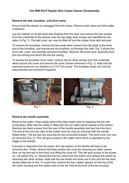
Lay the cleaner on its left hand side (looking from the rear) and remove the two screws<br />
from the underside of the cleaner near the top edge. Both screws are identified by the<br />
letter A (Fig. 1). The belt cover can now be lifted off and the rubber drive belt removed.<br />
To remove the brushbar, remove the two small silver screws from the plate at the drive<br />
end of the brushbar, and manoeuvre the brushbar out through this hole. Fig. 2 shows the<br />
drive belt, cover, and partially removed brushbar. Recover the loose bush assembly from<br />
the non-driving end which fits into the casing.<br />
To access the brushbar drive motor, remove the six silver screws from the underside<br />
which secure the cover and remove the cover (shown removed in Fig. 1). Note that the<br />
rearmost screw (on my cleaner) is a T15 Torx screw. The brushbar motor can now be<br />
disconnected and removed if required.<br />
Fig. 1 Fig. 2<br />
Remove the handle assembly<br />
Remove the cable / hose caddy behind the clean water tank by releasing the two red<br />
turnbuckles. Note that the caddy is fitted with the red cable swivel release at the bottom.<br />
Remove ten black screws from the rear of the handle assembly and two from the front.<br />
The two at the front are right at the bottom and can only be removed with the handle<br />
folded down. The top two are securing the top turnbuckle bracket. The front cover can now<br />
be removed (Fig. 3). This will give access to the water valve which is operated by the<br />
trigger in the handle.<br />
If access is required to the fan motor, the rear section of the handle will have to be<br />
removed also. Firstly, remove the base section top cover by removing six black screws<br />
(four on top and two at the front) and lifting the cover off. This will give access to the power<br />
on / off switch (Fig. 4). Disconnect the four wires from the switch and release the switch by<br />
removing two silver screws. Note that the two brown live wires are in line and the two blue<br />
neutral wires are in line. To avoid loss, remove the four rubber spacers on the top of the<br />
fan motor housing and the rubber seal on the fan inlet at the front of the fan housing.
Fig.3 Fig. 4<br />
Now remove the two silver screws from the water valve and remove the valve,<br />
disconnecting the two hoses, black at the front and yellow at the rear, secured with hose<br />
clips, and also disconnect the clear hose from the outlet below the clean water tank. It may<br />
help the disconnection of these hoses if they are softened by using a hair dryer or similar.<br />
Unscrew and remove the mains cable clamp near the top of the handle.<br />
Now press the handle release foot switch on the left to retract the locking mechanism and<br />
ease the handle out of its location on both sides, while assisting the three hoses through<br />
the hole in the handle on the left hand side and the mains cable on the right hand side.<br />
The handle can now be completely removed (Fig. 5).<br />
Remove the fan assembly<br />
Now disconnect the red hose secured by a hose clip from the wash tool valve (shown<br />
disconnected in Fig. 5). There are five screws which now have to be removed, one silver<br />
screw on the underside adjacent to the previously removed brushbar drive motor cover<br />
and four black screws on top. One of these is located below the location of the power on /<br />
off switch and one is in a similar position on the left hand side. There is also one screw on<br />
each side towards the rear of each foot pedal.<br />
Lift off the fan motor cover while assisting the red hose and mains wiring through the holes<br />
in the cover (Fig. 6). Note the location of the ferrite core through which the motor wires<br />
pass in case this becomes dislodged.
Fig. 5 Fig. 6<br />
Remove the two small screws which attach the microswitch to the fan housing and move<br />
the microswitch away from the housing to be reattached when the fan assembly is<br />
replaced. This microswitch stops the brushbar rotating when the handle is in the upright<br />
position. Now ease up the fan motor assembly out of its location. The fan motor<br />
connections are still attached. Note the junction box location in front of the fan. Inside this<br />
junction box are two sets of five wires crimped together. To avoid separating all this wiring<br />
and joining it again later, cut the cable which feeds the fan a few inches away from the<br />
junction box. The two cores can then be through-crimped to the new fan motor cable later.<br />
The fan assembly can now be removed (Fig. 7). This photograph actually shows my new<br />
one which I purchased used, and it came in its case with the microswitch attached but I<br />
used my old microswitch to avoid having to through-joint the wires.<br />
To remove the fan motor from its casing, remove the rubber mat which is clipped to the<br />
underside, remove four black screws from the front of the casing and four from the rear,<br />
and remove the casing front and rear covers. The motor can now be pushed out of its<br />
casing (Fig. 8).<br />
Fig. 7 Fig. 8<br />
Reassembly is a reversal of the above, but note the following. Remember to replace the<br />
rubber mat under the fan (Fig. 7), the rubber spacers on top (Fig. 4), and the rubber seal<br />
on the fan inlet (Fig. 2).<br />
Remember to reconnect the fan motor wiring. You can use insulated straight-through<br />
crimps, closed end crimps, or straight through terminals which should be wrapped in<br />
insulating tape. I used closed end crimps, similar to those used by <strong>Vax</strong> in the junction box.