iPCL System Description and Programming Manual - Nuova Elva
iPCL System Description and Programming Manual - Nuova Elva
iPCL System Description and Programming Manual - Nuova Elva

Create successful ePaper yourself
Turn your PDF publications into a flip-book with our unique Google optimized e-Paper software.
Typ3 osa / PNC<br />
<strong>iPCL</strong><br />
<strong>System</strong> <strong>Description</strong> <strong>and</strong> <strong>Programming</strong> <strong>Manual</strong><br />
Edition<br />
101<br />
Antriebs- und Steuerungstechnik
Typ3 osa / PNC<br />
<strong>iPCL</strong><br />
<strong>System</strong> <strong>Description</strong> <strong>and</strong> <strong>Programming</strong> <strong>Manual</strong><br />
1070 073 875-101 (02.04) GB<br />
Software release: V7.x<br />
E 2002<br />
by Bosch Rexroth AG, Erbach / Germany<br />
All rights reserved, including applications for protective rights.<br />
Reproduction or distribution by any means subject to our prior written permission.<br />
Discretionary charge 12.– EUR
Contents<br />
1070 073 875-101 (02.04) GB<br />
Contents V<br />
Page<br />
1 Safety Instructions . . . . . . . . . . . . . . . . . . . . . . . . . . . . 1–1<br />
1.1 Intended use . . . . . . . . . . . . . . . . . . . . . . . . . . . . . . . . . . . . . . . . . . . 1–1<br />
1.2 Qualified personnel . . . . . . . . . . . . . . . . . . . . . . . . . . . . . . . . . . . . . 1–2<br />
1.3 Safety markings on products . . . . . . . . . . . . . . . . . . . . . . . . . . . . . 1–3<br />
1.4 Safety instructions in this manual . . . . . . . . . . . . . . . . . . . . . . . . . 1–4<br />
1.5 Safety instructions for the described product . . . . . . . . . . . . . . . . 1–5<br />
1.6 Documentation, software release <strong>and</strong> trademarks . . . . . . . . . . . 1–7<br />
2 <strong>System</strong> Overview . . . . . . . . . . . . . . . . . . . . . . . . . . . . . 2–1<br />
2.1 Functionality . . . . . . . . . . . . . . . . . . . . . . . . . . . . . . . . . . . . . . . . . . . 2–1<br />
2.2 Hardware platforms . . . . . . . . . . . . . . . . . . . . . . . . . . . . . . . . . . . . . 2–2<br />
2.3 <strong>iPCL</strong> extensions . . . . . . . . . . . . . . . . . . . . . . . . . . . . . . . . . . . . . . . 2–3<br />
2.4 Data backup . . . . . . . . . . . . . . . . . . . . . . . . . . . . . . . . . . . . . . . . . . . 2–4<br />
3 Configuration . . . . . . . . . . . . . . . . . . . . . . . . . . . . . . . . . 3–1<br />
3.1 Connecting to the system . . . . . . . . . . . . . . . . . . . . . . . . . . . . . . . . 3–1<br />
3.2 Startup of the <strong>iPCL</strong> . . . . . . . . . . . . . . . . . . . . . . . . . . . . . . . . . . . . . . 3–2<br />
3.2.1 Initialization of the <strong>iPCL</strong> . . . . . . . . . . . . . . . . . . . . . . . . . . . . . . . . . . 3–3<br />
3.2.2 Startup diagram . . . . . . . . . . . . . . . . . . . . . . . . . . . . . . . . . . . . . . . . 3–4<br />
3.2.3 Startup conditions . . . . . . . . . . . . . . . . . . . . . . . . . . . . . . . . . . . . . . 3–7<br />
3.3 Data backup <strong>and</strong> residual characteristics of the <strong>iPCL</strong> . . . . . . . . 3–9<br />
3.3.1 Data backup depending on hardware platform . . . . . . . . . . . . . . 3–9<br />
3.3.2 Defining residual areas in the OM2 . . . . . . . . . . . . . . . . . . . . . . . . 3–12<br />
3.3.3 Residual characteristics depending on hardware platform . . . . 3–14<br />
3.3.4 Residual operation . . . . . . . . . . . . . . . . . . . . . . . . . . . . . . . . . . . . . . 3–15<br />
3.3.5 Non-residual operation . . . . . . . . . . . . . . . . . . . . . . . . . . . . . . . . . . 3–15<br />
3.3.6 Buffer failure, data backup fault . . . . . . . . . . . . . . . . . . . . . . . . . . . 3–16<br />
4 Peripheral Operation . . . . . . . . . . . . . . . . . . . . . . . . . . 4–1<br />
4.1 Data exchange machine PLC . . . . . . . . . . . . . . . . . . . . . . . . 4–1<br />
4.2 PROFIBUS-DP . . . . . . . . . . . . . . . . . . . . . . . . . . . . . . . . . . . . . . . . . 4–2<br />
5 <strong>Programming</strong> Basics . . . . . . . . . . . . . . . . . . . . . . . . . . 5–1<br />
5.1 <strong>Programming</strong> . . . . . . . . . . . . . . . . . . . . . . . . . . . . . . . . . . . . . . . . . . 5–1<br />
5.2 Program Structure . . . . . . . . . . . . . . . . . . . . . . . . . . . . . . . . . . . . . . 5–2<br />
5.3 Module Types . . . . . . . . . . . . . . . . . . . . . . . . . . . . . . . . . . . . . . . . . . 5–2<br />
5.3.1 Organization modules (OM) . . . . . . . . . . . . . . . . . . . . . . . . . . . . . . 5–2<br />
5.3.2 Program modules . . . . . . . . . . . . . . . . . . . . . . . . . . . . . . . . . . . . . . . 5–3<br />
5.3.3 Data modules . . . . . . . . . . . . . . . . . . . . . . . . . . . . . . . . . . . . . . . . . . 5–3<br />
5.3.4 APS modules . . . . . . . . . . . . . . . . . . . . . . . . . . . . . . . . . . . . . . . . . . 5–4<br />
5.4 Program Processing . . . . . . . . . . . . . . . . . . . . . . . . . . . . . . . . . . . . 5–5<br />
5.5 Time Monitoring . . . . . . . . . . . . . . . . . . . . . . . . . . . . . . . . . . . . . . . . 5–6<br />
5.6 I/O state . . . . . . . . . . . . . . . . . . . . . . . . . . . . . . . . . . . . . . . . . . . . . . . 5–6<br />
5.6.1 Fixing inputs, outputs & markers . . . . . . . . . . . . . . . . . . . . . . . . . . 5–6<br />
5.6.2 Updating timers . . . . . . . . . . . . . . . . . . . . . . . . . . . . . . . . . . . . . . . . 5–7<br />
5.6.3 Cyclical processing . . . . . . . . . . . . . . . . . . . . . . . . . . . . . . . . . . . . . 5–7<br />
5.6.4 Application program structure . . . . . . . . . . . . . . . . . . . . . . . . . . . . 5–7<br />
5.7 Initialisation table OM2 . . . . . . . . . . . . . . . . . . . . . . . . . . . . . . . . . . 5–8<br />
5.7.1 Printout of the OM2<strong>iPCL</strong> . . . . . . . . . . . . . . . . . . . . . . . . . . . . . . . . . 5–9<br />
5.8 Module reference list . . . . . . . . . . . . . . . . . . . . . . . . . . . . . . . . . . . .<br />
5–14
VI<br />
Contents<br />
5.9 Module existence . . . . . . . . . . . . . . . . . . . . . . . . . . . . . . . . . . . . . . . 5–15<br />
5.10 Module size . . . . . . . . . . . . . . . . . . . . . . . . . . . . . . . . . . . . . . . . . . . . 5–15<br />
5.11 Module start address . . . . . . . . . . . . . . . . . . . . . . . . . . . . . . . . . . . . 5–16<br />
5.12 Module header . . . . . . . . . . . . . . . . . . . . . . . . . . . . . . . . . . . . . . . . . 5–16<br />
5.13 OM9 error module . . . . . . . . . . . . . . . . . . . . . . . . . . . . . . . . . . . . . . 5–17<br />
5.14 Fixation . . . . . . . . . . . . . . . . . . . . . . . . . . . . . . . . . . . . . . . . . . . . . . . 5–17<br />
5.15 Parameterized Modules . . . . . . . . . . . . . . . . . . . . . . . . . . . . . . . . . 5–18<br />
5.16 Time-controlled program processing . . . . . . . . . . . . . . . . . . . . . . . 5–19<br />
5.17 Application stack . . . . . . . . . . . . . . . . . . . . . . . . . . . . . . . . . . . . . . . 5–20<br />
6 <strong>iPCL</strong> addressing . . . . . . . . . . . . . . . . . . . . . . . . . . . . . . 6–1<br />
6.1 Oper<strong>and</strong> & module identifiers, module list . . . . . . . . . . . . . . . . . . 6–1<br />
6.2 Assignments in the special marker area . . . . . . . . . . . . . . . . . . . . 6–2<br />
6.3 <strong>System</strong> area assignment . . . . . . . . . . . . . . . . . . . . . . . . . . . . . . . . . 6–4<br />
6.4 Periphery status . . . . . . . . . . . . . . . . . . . . . . . . . . . . . . . . . . . . . . . . 6–6<br />
6.5 Data formats . . . . . . . . . . . . . . . . . . . . . . . . . . . . . . . . . . . . . . . . . . . 6–7<br />
6.6 Register structure . . . . . . . . . . . . . . . . . . . . . . . . . . . . . . . . . . . . . . . 6–11<br />
6.7 Representation of constants . . . . . . . . . . . . . . . . . . . . . . . . . . . . . . 6–12<br />
6.8 Program module calls . . . . . . . . . . . . . . . . . . . . . . . . . . . . . . . . . . . 6–12<br />
6.9 Jump instructions . . . . . . . . . . . . . . . . . . . . . . . . . . . . . . . . . . . . . . . 6–12<br />
6.10 Bit- <strong>and</strong> module addresses . . . . . . . . . . . . . . . . . . . . . . . . . . . . . . . 6–13<br />
6.11 Byte addresses . . . . . . . . . . . . . . . . . . . . . . . . . . . . . . . . . . . . . . . . . 6–13<br />
6.12 Addressing modes . . . . . . . . . . . . . . . . . . . . . . . . . . . . . . . . . . . . . . 6–14<br />
6.12.1 Absolute addressable oper<strong>and</strong>s . . . . . . . . . . . . . . . . . . . . . . . . . . . 6–14<br />
6.12.2 Direct addressing of all absolute addressable oper<strong>and</strong>s . . . . . . 6–14<br />
6.12.3 Register-to-register addressing . . . . . . . . . . . . . . . . . . . . . . . . . . . 6–14<br />
6.12.4 Register indirect addressing . . . . . . . . . . . . . . . . . . . . . . . . . . . . . . 6–15<br />
6.12.5 <strong>iPCL</strong> indirect addressing . . . . . . . . . . . . . . . . . . . . . . . . . . . . . . . . . 6–16<br />
6.13 Parameter transfer . . . . . . . . . . . . . . . . . . . . . . . . . . . . . . . . . . . . . . 6–18<br />
6.14 Addressing limits . . . . . . . . . . . . . . . . . . . . . . . . . . . . . . . . . . . . . . . 6–19<br />
7 Instruction set . . . . . . . . . . . . . . . . . . . . . . . . . . . . . . . . 7–1<br />
7.1 Structure of controller instructions . . . . . . . . . . . . . . . . . . . . . . . . . 7–1<br />
7.2 Flags . . . . . . . . . . . . . . . . . . . . . . . . . . . . . . . . . . . . . . . . . . . . . . . . . 7–1<br />
7.3 Key to abbreviations . . . . . . . . . . . . . . . . . . . . . . . . . . . . . . . . . . . . 7–2<br />
7.4 Bit instructions . . . . . . . . . . . . . . . . . . . . . . . . . . . . . . . . . . . . . . . . . 7–3<br />
7.5 Timer programming . . . . . . . . . . . . . . . . . . . . . . . . . . . . . . . . . . . . . 7–4<br />
7.5.1 Timer instructions . . . . . . . . . . . . . . . . . . . . . . . . . . . . . . . . . . . . . . . 7–5<br />
7.5.2 Time format . . . . . . . . . . . . . . . . . . . . . . . . . . . . . . . . . . . . . . . . . . . . 7–6<br />
7.5.3 Timer diagrams . . . . . . . . . . . . . . . . . . . . . . . . . . . . . . . . . . . . . . . . . 7–7<br />
7.6 Counter instructions . . . . . . . . . . . . . . . . . . . . . . . . . . . . . . . . . . . . . 7–8<br />
7.7 Digital links . . . . . . . . . . . . . . . . . . . . . . . . . . . . . . . . . . . . . . . . . . . . 7–9<br />
7.8 SWAP instructions . . . . . . . . . . . . . . . . . . . . . . . . . . . . . . . . . . . . . . 7–9<br />
7.9 Compare instruction . . . . . . . . . . . . . . . . . . . . . . . . . . . . . . . . . . . . . 7–10<br />
7.10 Load instructions . . . . . . . . . . . . . . . . . . . . . . . . . . . . . . . . . . . . . . . 7–12<br />
7.11 Tranfer instructions . . . . . . . . . . . . . . . . . . . . . . . . . . . . . . . . . . . . . 7–13<br />
7.12 Convert instructions . . . . . . . . . . . . . . . . . . . . . . . . . . . . . . . . . . . . . 7–14<br />
7.13 Increment & Decrement instructions . . . . . . . . . . . . . . . . . . . . . . . 7–15<br />
7.14 Stack instructions . . . . . . . . . . . . . . . . . . . . . . . . . . . . . . . . . . . . . . . 7–15<br />
7.15 No operation instructions & CARRY manipulations . . . . . . . . . . 7–15<br />
7.16 Shift instructions . . . . . . . . . . . . . . . . . . . . . . . . . . . . . . . . . . . . . . . . 7–16<br />
7.17 Rotate instructions . . . . . . . . . . . . . . . . . . . . . . . . . . . . . . . . . . . . . . 7–17<br />
7.18 Fixed point arithmetic . . . . . . . . . . . . . . . . . . . . . . . . . . . . . . . . . . . . 7–18<br />
7.18.1 Add instructions . . . . . . . . . . . . . . . . . . . . . . . . . . . . . . . . . . . . . . . . 7–18<br />
7.18.2 Substract instructions . . . . . . . . . . . . . . . . . . . . . . . . . . . . . . . . . . . 7–20<br />
7.18.3 Multiply instructions . . . . . . . . . . . . . . . . . . . . . . . . . . . . . . . . . . . . . 7–22<br />
7.18.4 Divide instructions . . . . . . . . . . . . . . . . . . . . . . . . . . . . . . . . . . . . . .<br />
7–23<br />
1070 073 875-101 (02.04) GB
1070 073 875-101 (02.04) GB<br />
Contents VII<br />
7.19 Floating point arithmetic . . . . . . . . . . . . . . . . . . . . . . . . . . . . . . . . . 7–24<br />
7.19.1 Loadfloating point values . . . . . . . . . . . . . . . . . . . . . . . . . . . . . . . . 7–25<br />
7.19.2 TRANSFERfloating point values . . . . . . . . . . . . . . . . . . . . . . . . . . 7–26<br />
7.19.3 CONVERT number formats (floating point integer) . . . . . . . 7–26<br />
7.19.4 Convert data formats (REAL LREAL) . . . . . . . . . . . . . . . . . . 7–26<br />
7.19.5 Removing decimal positions . . . . . . . . . . . . . . . . . . . . . . . . . . . . . . 7–27<br />
7.19.6 Comparefloating point values . . . . . . . . . . . . . . . . . . . . . . . . . . . . . 7–27<br />
7.19.7 Calculating with floating point values . . . . . . . . . . . . . . . . . . . . . . . 7–28<br />
7.19.8 Forming absolute value . . . . . . . . . . . . . . . . . . . . . . . . . . . . . . . . . . 7–29<br />
7.19.9 Extracting square root . . . . . . . . . . . . . . . . . . . . . . . . . . . . . . . . . . . 7–29<br />
7.19.10 Exponentiation . . . . . . . . . . . . . . . . . . . . . . . . . . . . . . . . . . . . . . . . . 7–29<br />
7.19.11 Logarithmic functions . . . . . . . . . . . . . . . . . . . . . . . . . . . . . . . . . . . . 7–30<br />
7.19.12 Trigonometric functions floating point . . . . . . . . . . . . . . . . . . . . . . 7–30<br />
7.20 Parameter assignments . . . . . . . . . . . . . . . . . . . . . . . . . . . . . . . . . 7–31<br />
7.21 Local symbol names & auxiliary markers for program tracking . 7–31<br />
7.22 <strong>System</strong> variable . . . . . . . . . . . . . . . . . . . . . . . . . . . . . . . . . . . . . . . . 7–31<br />
7.23 Jump instructions . . . . . . . . . . . . . . . . . . . . . . . . . . . . . . . . . . . . . . . 7–32<br />
7.24 Module calls . . . . . . . . . . . . . . . . . . . . . . . . . . . . . . . . . . . . . . . . . . . 7–34<br />
7.25 End of module instruction . . . . . . . . . . . . . . . . . . . . . . . . . . . . . . . . 7–36<br />
7.26 FIFO instructions . . . . . . . . . . . . . . . . . . . . . . . . . . . . . . . . . . . . . . . 7–37<br />
7.27 Block comm<strong>and</strong>s . . . . . . . . . . . . . . . . . . . . . . . . . . . . . . . . . . . . . . . 7–38<br />
7.28 Interrupt instructions for time-controlled processing . . . . . . . . . . 7–41<br />
7.29 Program stop <strong>and</strong> program end . . . . . . . . . . . . . . . . . . . . . . . . . . . 7–41<br />
7.30 Backing up <strong>and</strong> loading residual areas . . . . . . . . . . . . . . . . . . . . . 7–42<br />
8 Processing Times . . . . . . . . . . . . . . . . . . . . . . . . . . . . . 8–1<br />
9 Sample Programs . . . . . . . . . . . . . . . . . . . . . . . . . . . . . 9–1<br />
9.1 Indirect addressing . . . . . . . . . . . . . . . . . . . . . . . . . . . . . . . . . . . . . . 9–1<br />
9.2 Compare instruction examples . . . . . . . . . . . . . . . . . . . . . . . . . . . . 9–2<br />
9.3 FIFO instruction examples . . . . . . . . . . . . . . . . . . . . . . . . . . . . . . . 9–3<br />
A Appendix . . . . . . . . . . . . . . . . . . . . . . . . . . . . . . . . . . . . . A–1<br />
A.1 Abbreviations . . . . . . . . . . . . . . . . . . . . . . . . . . . . . . . . . . . . . . . . . . A–1<br />
A.2 Index . . . . . . . . . . . . . . . . . . . . . . . . . . . . . . . . . . . . . . . . . . . . . . . . .<br />
A–2
VIII<br />
Notes:<br />
Contents<br />
1070 073 875-101 (02.04) GB
1 Safety Instructions<br />
1.1 Intended use<br />
1070 073 875-101 (02.04) GB<br />
Safety Instructions 1–1<br />
Before you start working with the <strong>iPCL</strong> , we recommend that you thoroughly<br />
familiarize yourself with the contents of this manual. Keep this manual in a<br />
place where it is always accessible to all users.<br />
This manual contains information required for the proper use of this product.<br />
However, for reasons of structural clarity, the manual cannot provide exhaustive<br />
details regarding all available combinations of functional options.<br />
Similarly, it is feasible to consider every conceivable integration or operating<br />
scenario within the confines of this manual.<br />
The Typ3 osa <strong>and</strong> PNC controls serve as<br />
D activate feed drives, spindles <strong>and</strong> auxiliary axes of a machine tool via<br />
SERCOS interface for the purpose of guiding a processing tool along a<br />
programmed path to process a workpiece (CNC). Furthermore, a PLC is<br />
required with appropriate I/O components which – in communication with<br />
the actual CNC – controls the machine processing cycles holistically <strong>and</strong><br />
acts as a technical safety monitor.<br />
D program contours <strong>and</strong> the processing technology (path feedrate, spindle<br />
speed, tool change) of a workpiece.<br />
Any other application is deemed improper use!<br />
The products described hereunder<br />
D have been developed, manufactured, tested <strong>and</strong> documented in compliance<br />
with the safety st<strong>and</strong>ards. These products pose no danger to persons<br />
or property if they are used in accordance with the h<strong>and</strong>ling<br />
stipulations <strong>and</strong> safety notes prescribed for their configuration, mounting,<br />
<strong>and</strong> proper operation.<br />
D comply with the requirements of<br />
D the EMC Directives (89/336/EEC, 93/68/EEC <strong>and</strong> 93/44/EEC)<br />
D the Low-Voltage Directive (73/23/EEC)<br />
D the harmonized st<strong>and</strong>ards EN 50081-2 <strong>and</strong> EN 50082-2<br />
D are designed for operation in industrial environments, i.e.<br />
D no direct connection to public low-voltage power supply,<br />
D connection to the medium- or high-voltage system via a transformer.<br />
In residential environments, in trade <strong>and</strong> commerce as well as small enterprises<br />
class A equipment may only be used if the following warning is<br />
attached:<br />
. This is a Class A device. In a residential area, this device may cause<br />
radio interference. In such case, the user may be required to introduce<br />
suitable countermeasures, <strong>and</strong> to bear the cost of the same.<br />
The faultless, safe functioning of the product requires proper transport, storage,<br />
erection <strong>and</strong> installation as well as careful operation.
1–2<br />
Safety Instructions<br />
1.2 Qualified personnel<br />
The requirements as to qualified personnel depend on the qualification profiles<br />
described by ZVEI (central association of the electrical industry) <strong>and</strong><br />
VDMA (association of German machine <strong>and</strong> plant builders) in:<br />
Weiterbildung in der Automatisierungstechnik<br />
edited by: ZVEI <strong>and</strong> VDMA<br />
MaschinenbauVerlag<br />
Postfach 71 08 64<br />
D-60498 Frankfurt.<br />
This manual is intended for project engineers <strong>and</strong> NC specialists, who are<br />
familiar with programmable logic controllers (PLC). A special knowledge of<br />
how to configure <strong>and</strong> commission electrical equipment is also required<br />
<strong>Programming</strong>, start <strong>and</strong> operation as well as the modification of program<br />
parameters is reserved to properly trained personnel! This personnel must<br />
be able to judge potential hazards arising from programming, program<br />
changes <strong>and</strong> in general from the mechanical, electrical, or electronic equipment.<br />
Interventions in the hardware <strong>and</strong> software of our products, unless described<br />
otherwise in this manual, are reserved to our specialized personnel.<br />
Tampering with the hardware or software, ignoring warning signs attached to<br />
the components, or non-compliance with the warning notes given in this<br />
manual may result in serious bodily injury or material damage.<br />
Only electrotechnicians as recognized under IEV 826-09-01 (modified) who<br />
are familiar with the contents of this manual may install <strong>and</strong> service the products<br />
described.<br />
Such personnel are<br />
D those who, being well trained <strong>and</strong> experienced in their field <strong>and</strong> familiar<br />
with the relevant norms, are able to analyze the jobs being carried out<br />
<strong>and</strong> recognize any hazards which may have arisen.<br />
D those who have acquired the same amount of expert knowledge through<br />
years of experience that would normally be acquired through formal<br />
technical training.<br />
With regard to the foregoing, please note our comprehensive range of training<br />
courses. For current information, the web shop <strong>and</strong> online booking of<br />
seminars please visit our website http://www.bosch.de/at/didactic. Our training<br />
center will be pleased to provide you with further information, telephone:<br />
(+49) (0 60 62) 78–258.<br />
1070 073 875-101 (02.04) GB
1.3 Safety markings on products<br />
1070 073 875-101 (02.04) GB<br />
Warning of dangerous electrical voltage!<br />
DANGER! Corrosive battery acid!<br />
Electrostatically sensitive components!<br />
Hazardous light emissions<br />
(optical fibre cable emitters)!<br />
Disconnect mains power before opening!<br />
Lug for connecting PE conductor only!<br />
Connection of shield conductor only<br />
Safety Instructions 1–3
1–4<br />
Safety Instructions<br />
1.4 Safety instructions in this manual<br />
DANGEROUS ELECTRICAL VOLTAGE<br />
This symbol is used to warn of a dangerous electrical voltage. The failure<br />
to observe the instructions in this manual in whole or in part may result<br />
in personal injury.<br />
DANGER<br />
This symbol is used wherever insufficient or lacking compliance with instructions<br />
may result in personal injury.<br />
CAUTION<br />
This symbol is used wherever insufficient or lacking compliance with instructions<br />
may result in damage to equipment or data files.<br />
. This symbol is used to draw the user’s attention to special circumstances.<br />
L This symbol is used if user activities are required.<br />
1070 073 875-101 (02.04) GB
1.5 Safety instructions for the described product<br />
1070 073 875-101 (02.04) GB<br />
Safety Instructions 1–5<br />
DANGER<br />
Danger of life through inadequate EMERGENCY-STOP devices!<br />
EMERGENCY-STOP devices must be active <strong>and</strong> within reach in all<br />
system modes. Releasing an EMERGENCY-STOP device must not<br />
result in an uncontrolled restart of the system!<br />
First check the EMERGENCY-STOP circuit, then switch the system<br />
on!<br />
DANGER<br />
Risk of personal injury <strong>and</strong> equipment damage!<br />
Always subject new programmes to initial tests while inhibiting axis<br />
movements. For this purpose, as a function of the AUTOMATIC<br />
mode, the controller provides the option to block axis movements or<br />
auxiliary functions by means of special softkey comm<strong>and</strong>s.<br />
DANGER<br />
Incorrect or undesired control unit response!<br />
Bosch accepts no liability for damage resulting from the execution<br />
of an NC program, an individual NC block or the manual movement<br />
of axes!<br />
Furthermore, Bosch accepts no liability for consequential damage<br />
which could have been avoided by programming the PLC appropriately!<br />
DANGER<br />
Retrofits or modifications may adversely affect the safety of the<br />
products described!<br />
The consequences may include severe injury, damage to equipment,<br />
or environmental hazards. Possible retrofits or modifications to the<br />
system using third-party equipment therefore have to be approved<br />
by Bosch.<br />
DANGEROUS ELECTRICAL VOLTAGE<br />
Unless described otherwise, maintenance works must be performed<br />
on inactive systems! The system must be protected against unauthorized<br />
or accidental reclosing.<br />
Measuring or test activities on the live system are reserved to qualified<br />
electrical personnel!
1–6<br />
Safety Instructions<br />
DANGER<br />
Tool or axis movements!<br />
Feed <strong>and</strong> spindle motors generate very powerful mechanical forces<br />
<strong>and</strong> can accelerate very quickly due to their high dynamics.<br />
D Always stay outside the danger area of an active machine tool!<br />
D Never deactivate safety-relevant functions!<br />
D Report any malfunction of the unit to your servicing <strong>and</strong> repairs<br />
department immediately!<br />
CAUTION<br />
Use only spare parts approved by Bosch!<br />
CAUTION<br />
Danger to the module!<br />
All ESD protection measures must be observed when using the<br />
module! Prevent electrostatic discharges!<br />
The following protective measures must be observed for modules <strong>and</strong> components<br />
sensitive to electrostatic discharge (ESD)!<br />
D Personnel responsible for storage, transport, <strong>and</strong> h<strong>and</strong>ling must have<br />
training in ESD protection.<br />
D ESD-sensitive components must be stored <strong>and</strong> transported in the prescribed<br />
protective packaging.<br />
D ESD-sensitive components may only be h<strong>and</strong>led at special ESD-workplaces.<br />
D Personnel, working surfaces, as well as all equipment <strong>and</strong> tools which<br />
may come into contact with ESD-sensitive components must have the<br />
same potential (e.g. by grounding).<br />
D Wear an approved grounding bracelet. The grounding bracelet must be<br />
connected with the working surface through a cable with an integrated<br />
1 MW resistor.<br />
D ESD-sensitive components may by no means come into contact with<br />
chargeable objects, including most plastic materials.<br />
D When ESD-sensitive components are installed in or removed from equipment,<br />
the equipment must be de-energized.<br />
1070 073 875-101 (02.04) GB
1.6 Documentation, software release <strong>and</strong> trademarks<br />
Documentation<br />
1070 073 875-101 (02.04) GB<br />
Safety Instructions 1–7<br />
This manual provides details of the programming <strong>and</strong> operation of the <strong>iPCL</strong>.<br />
Not included are general procedures for project management <strong>and</strong> installation<br />
of controllers <strong>and</strong> their associated hardware.<br />
Overview of available documentation Part no.<br />
Typ3 osa – Interface conditions<br />
for project engineering <strong>and</strong> maintenance<br />
German English<br />
1070 073 704 1070 073 736<br />
Typ3 osa – Software installation 1070 073 796 1070 073 797<br />
Decription of functions 1070 073 870 –<br />
MACODA<br />
Operation <strong>and</strong> configuration of the machine<br />
parameters<br />
Operating instructions<br />
St<strong>and</strong>ard operator interface<br />
1070 073 705 1070 073 742<br />
1070 073 726 1070 073 739<br />
Operating instructions – Diagnostics Tools 1070 073 779 1070 073 780<br />
Error Messages 1070 073 798 1070 073 799<br />
PLC project planning manual,<br />
Software interfaces of the integrated PLC<br />
<strong>iPCL</strong> system description <strong>and</strong><br />
programming manual<br />
ICL700 system description,<br />
Program structure of the integrated PLC<br />
ICL700<br />
DIN programming manual<br />
for programming to DIN 66025<br />
1070 073 728 1070 073 741<br />
1070 073 874 1070 073 875<br />
1070 073 706 1070 073 737<br />
1070 073 725 1070 073 738<br />
CPL programming manual 1070 073 727 1070 073 740<br />
CPL-Debugger Operating instructions 1070 073 872 –<br />
Tool Management – Parameterization 1070 073 782 1070 073 793<br />
Software PLC<br />
Development environment for Windows NT<br />
Measuring cycles for<br />
touch-trigger switching probes<br />
1070 073 783 1070 073 792<br />
1070 073 788 1070 073 789<br />
Universal Milling Cycles – 1070 073 795<br />
. In this manual the floppy disk drive always uses drive letter A:, <strong>and</strong> the<br />
hard disk drive always uses drive letter C:.<br />
Special keys or key combinations are shown enclosed in pointed brackets:<br />
D Named keys: e.g., , , <br />
D Key combinations (pressed simultaneously): e.g., +
1–8<br />
Release<br />
Trademarks<br />
Safety Instructions<br />
. The descriptive information contained in this manual applies to:<br />
Software version: V7.x<br />
The current release number of the individual software modules can be<br />
viewed by selecting the ’Control-Diagnostics’ softkey in the ’Diagnostics’<br />
group operating mode.<br />
The software version of Windows95 or WindowsNT may be displayed as follows:<br />
1. Click the right mouse button on the My Computer icon on your desktop.<br />
2. Select Properties.<br />
All trademarks of software installed on Bosch products upon delivery are the<br />
property of the respective manufacturer.<br />
Upon delivery, all installed software is copyright-protected. The software<br />
may only be reproduced with the approval of Bosch or in accordance with the<br />
license agreement of the respective manufacturer.<br />
MS-DOSr <strong>and</strong> Windowst are registered trademarks of Microsoft Corporation.<br />
PROFIBUSr is a registered trademark of the PROFIBUS Nutzerorganisation<br />
e.V. (user organization).<br />
SERCOS interfacet is a registered trademark of the SERCOS interface<br />
Joint VDW/ZVEI Working Committee.<br />
1070 073 875-101 (02.04) GB
2 <strong>System</strong> Overview<br />
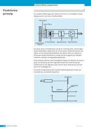
2.1 Functionality<br />
1070 073 875-101 (02.04) GB<br />
<strong>System</strong> Overview 2–1<br />
<strong>iPCL</strong> is a software PLC integrated into the NC control. Without additional<br />
hardware <strong>iPCL</strong> is integrated into:<br />
D the PNC plug-in card<br />
D the type 3 osa component group osa master P-L <strong>and</strong> osa master P-XL.<br />
Thus a secure functionality is assured independently of Windows.<br />
I/O’s are connected via PROFIBUS-DP, enabling RM65M-16DP, B~IOmodules<br />
to be used, for example.<br />
For the operation <strong>and</strong> programming of <strong>iPCL</strong>, the following configuration software<br />
is required:<br />
WinSPS: Creation of the PLC application program with functional extensions<br />
for communication between PLC <strong>and</strong> NC (APS modules)<br />
WinDP: Configuration of the PROFIBUS-DP<br />
Communications with the WinSPS, WinDP <strong>and</strong> other programs are h<strong>and</strong>led<br />
by the TCP/IP st<strong>and</strong>ard protocol with the use of the BUEP (Bosch transfer<br />
protocol) comm<strong>and</strong> language.<br />
For the creation of the PLC program or individual program modules in the<br />
programming language C, the C compiler <strong>and</strong> linker are also required.<br />
. For additional essentials related to <strong>iPCL</strong> <strong>and</strong> to operating decentralized<br />
peripherals via the PROFIBUS-DP, refer to the Online Help in<br />
WinSPS <strong>and</strong> WinDP.
2–2<br />
<strong>System</strong> Overview<br />
2.2 Hardware platforms<br />
<strong>iPCL</strong> in PNC (e.g. in the operating terminal BT205)<br />
Decentralised I/O’s<br />
D Decentr. I/O<br />
RM65M-16DP<br />
D B~IO K-DP<br />
D B~IO K-DP<br />
+−<br />
<strong>iPCL</strong> is integrated in:<br />
D the PNC plug-in card<br />
D the Typ3 osa component group osa master P-L <strong>and</strong> osa master P-XL.<br />
PROFIBUS-DP<br />
PROFIBUS-DP<br />
<strong>iPCL</strong> in the osa master P-L/XL (Typ3 osa)<br />
Decentralised I/O’s<br />
D Decentr. I/O<br />
RM65M-16DP<br />
D B~IO K-DP<br />
D B~IO K-DP<br />
Example:<br />
osa rack 2,<br />
containing<br />
D osa master P-L<br />
D DCIO<br />
PROFIBUS-DP<br />
PROFIBUS-DP<br />
BT205 with PNC plug-in card<br />
<strong>and</strong> as PLC programming unit<br />
osa master P-L with <strong>iPCL</strong><br />
Typ3 osa<br />
control<br />
PNC<br />
Ethernet<br />
Alternative external PLC<br />
programming unit Ethernet<br />
PC operating panel, also<br />
as PLC programming unit<br />
Analogue I/O<br />
Digital I/O<br />
Ethernet<br />
network<br />
Main computer<br />
Ethernet<br />
Alternative external PLC<br />
programming unit Ethernet<br />
Ethernet<br />
network<br />
Main computer<br />
1070 073 875-101 (02.04) GB
2.3 <strong>iPCL</strong> extensions<br />
Additional options<br />
1070 073 875-101 (02.04) GB<br />
<strong>System</strong> Overview 2–3<br />
The maximum I/O area <strong>and</strong> the PLC user memory (MACODA<br />
parameter 2060 00210) are determined by licence:<br />
Type Peripherals User memory<br />
<strong>iPCL</strong>_1 (PNC) 16 kb for inputs<br />
16 kb for outputs<br />
<strong>iPCL</strong>_2 (PNC) 256 kb for inputs<br />
256 kb for outputs<br />
<strong>iPCL</strong>_3 (PNC) 8 kb for inputs<br />
8 kb for outputs<br />
<strong>iPCL</strong>_4<br />
(osa master P-<br />
L/XL)<br />
-256 bytes for inputs<br />
-256 bytes for outputs<br />
32 kbytes<br />
128 kbytes<br />
512 kbytes<br />
Default: 200 kb depending<br />
on free memory in the osa<br />
master P-L/XL<br />
Because the data field <strong>and</strong> data buffer are included in every hardware expansion<br />
level, they do not reduce the size of the user memory! Just like the<br />
program <strong>and</strong> organization modules, the data modules are stored in the PLC<br />
user memory.<br />
OPC server functions are available. It enables MADAP STUDIO to be used<br />
together with the PNC.
2–4<br />
<strong>System</strong> Overview<br />
2.4 Data backup<br />
PNC<br />
PNC hardware platform<br />
SDRAM<br />
<strong>iPCL</strong> memory<br />
PLC program<br />
(SoftSPS.bin)<br />
Fixationlist<br />
(Fix.bin)<br />
Status<br />
(Status.bin)<br />
Hard disk<br />
Mount directory<br />
<strong>iPCL</strong> uses PNC’s own memory (SDRAM) <strong>and</strong> the hard disk of the base unit<br />
into which the PNC is plugged.<br />
Optimum functional security of the <strong>iPCL</strong> in the PNC is attained by using a<br />
UPS (uninterruptible power supply), which bridges a potential power loss to<br />
allow essential PLC <strong>and</strong> NC data to be backed up to hard disk <strong>and</strong> leads to a<br />
delayed shut down of the Windows NT operating system.<br />
Data comparison<br />
for every<br />
amendment<br />
Base device (e.g. PC operating panel)<br />
Memory for<br />
RAM filing system<br />
PLC program<br />
(SoftSPS.bin)<br />
Fixation list<br />
(Fix.bin)<br />
Status<br />
(Status.bin)<br />
Parts program<br />
Machine data<br />
Backup<br />
on shutdown<br />
(as file)<br />
Memory for program<br />
execution<br />
residual data<br />
<strong>and</strong> areas <strong>and</strong><br />
FIFO’s<br />
Memory for cyclic<br />
backup<br />
residual data<br />
<strong>and</strong> areas <strong>and</strong><br />
FIFO’s<br />
RAM filing system backed up in a<br />
file:<br />
PLC program (SoftSPS.bin)<br />
Fixation list (Fix.bin)<br />
Status (Status.bin)<br />
Parts program<br />
Machine data<br />
residual data, areas <strong>and</strong> FIFO’S backed<br />
up in a file<br />
Backup by <strong>iPCL</strong><br />
on shutdown<br />
Backup on<br />
shutdown<br />
after <strong>iPCL</strong> has<br />
ended<br />
1070 073 875-101 (02.04) GB
osa master P-L/XL (SNCI4)<br />
osa master P-L/XL (SNCI4) hardware platform<br />
SDRAM<br />
Data<br />
comparison<br />
after every<br />
amendment<br />
SRAM<br />
FEPROM<br />
1070 073 875-101 (02.04) GB<br />
<strong>System</strong> Overview 2–5<br />
<strong>iPCL</strong> uses various memory areas of the component group<br />
osa master P-L/XL:<br />
D SDRAM (dynamic mamory) for PLC program <strong>and</strong> data in use.<br />
D SRAM (static memory) for PLC program <strong>and</strong> data for switched off control<br />
<strong>and</strong> cyclic backups.<br />
D FEPROM for additional back up of the PLC program.<br />
<strong>iPCL</strong> memory<br />
PLC program<br />
(SoftSPS.bin)<br />
Fixationlist<br />
(Fix.bin)<br />
Status<br />
(Status.bin)<br />
Memory for<br />
RAM filing system<br />
PLC program<br />
(SoftSPS.bin)<br />
Fixation list<br />
(Fix.bin)<br />
Status<br />
(Status.bin)<br />
Parts program<br />
Machine data<br />
usr-fep<br />
PLC program<br />
(SoftSPS.bin)<br />
<strong>Manual</strong> backup<br />
by comm<strong>and</strong><br />
Memory for program<br />
execution<br />
residual data<br />
<strong>and</strong> areas <strong>and</strong><br />
FIFO’s<br />
Memory for cyclic<br />
backup<br />
residual data<br />
<strong>and</strong> areas <strong>and</strong><br />
FIFO’s<br />
The data that have<br />
to be backed up<br />
cyclically are<br />
determined in the<br />
OM2 or under<br />
program control
2–6<br />
Notes:<br />
<strong>System</strong> Overview<br />
1070 073 875-101 (02.04) GB
3 Configuration<br />
3.1 Connecting to the system<br />
Registering <strong>iPCL</strong> via MACODA<br />
Interfacing with Peripherals<br />
<strong>System</strong> clock management<br />
1070 073 875-101 (02.04) GB<br />
Configuration 3–1<br />
<strong>iPCL</strong> has to be registered in the MACODA parameter 2060 00200. Apart<br />
from that further parameters can be changed:<br />
D 2060 00200: Selection of the PCL.<br />
Must be set to <strong>iPCL</strong> (= 4).<br />
D 2060 00210: Maximum size of the user program.<br />
For the PNC the size may be limited by<br />
licence, (for detailed information, refer to Section 2.3)<br />
D 2060 00211: Max PLC computing time in %.<br />
(see Section 8).<br />
The interfacing with peripherals is viy the serial filed bus system PROFI-<br />
BUS-DP via the PROFIBUS-DP Busmaster interface:<br />
D for base devices with PNC: on the ”PNC-PCI card”<br />
D for the Typ3 osa hardware: on the component group ”osa dc I/O”<br />
The maximum I/O area is determined by licence.<br />
Reference list:<br />
The bus master monitors the existence of slaves <strong>and</strong> transfers this data to<br />
the <strong>iPCL</strong>.<br />
Error functions:<br />
The error functions are dependent on the bus system used. The PROFI-<br />
BUS-DP field bus features a comprehensive diagnostic system whose<br />
messages are made available by the <strong>iPCL</strong> bus master.<br />
The system timing, which can be processed in the PLC program via the system<br />
area, is generated by the clock source onboard the PC.
3–2<br />
Configuration<br />
3.2 Startup of the <strong>iPCL</strong><br />
Mains ON<br />
Initialization<br />
Load PLC program<br />
Read inputs<br />
Load fixation list<br />
Stop comm<strong>and</strong> on<br />
”Stop”?<br />
n<br />
Restart<br />
Restart OM5<br />
available?<br />
n<br />
Final Initialization<br />
I/O state<br />
Cyclical program<br />
processing (OM1)<br />
Program error or<br />
stop request? y<br />
n<br />
RUN<br />
y<br />
y<br />
There follows the initialization <strong>and</strong> the start-up diagram for the <strong>iPCL</strong>. This<br />
procedure is the same for all hardware platforms.<br />
Cold start flag<br />
set?<br />
y<br />
Request error or<br />
stop<br />
eliminate<br />
Stop startup *)<br />
(Stop request)<br />
n<br />
Seriouserror?<br />
RUN<br />
n<br />
n<br />
Request error or<br />
stop<br />
eliminate<br />
Stop<br />
processing *)<br />
Restart OM5<br />
residual?<br />
Restart OM5<br />
(not residual)<br />
y<br />
y<br />
Trigger reset<br />
Eliminate error<br />
<strong>System</strong> stop<br />
Restart OM5<br />
(residual)<br />
Restart<br />
Restart OM7<br />
available?<br />
n<br />
*) at least one of the stop requests<br />
leads to a start-up stop or operating<br />
stop.<br />
S Startup mode=1 (PNC)<br />
S1 =1 (osa master P-L/XL)<br />
S no PLC program<br />
S no or missing fixation list<br />
S Residual error recognised<br />
(while residual test flag set)<br />
S<br />
no backup possible to SDRAM (PNC)<br />
or to SRAM (osa master)<br />
(while flag set for cyclical)<br />
backup in the OM2)<br />
y<br />
Restart OM7<br />
residual?<br />
n<br />
Restart OM7<br />
(not residual)<br />
y<br />
Restart OM7<br />
(residual)<br />
1070 073 875-101 (02.04) GB
3.2.1 Initialization of the <strong>iPCL</strong><br />
Initializing special markers<br />
Initialization values<br />
Exceptions for initial start<br />
1070 073 875-101 (02.04) GB<br />
Configuration 3–3<br />
In the initialization phase the <strong>iPCL</strong> operating system starts up.<br />
The special markers SM21.0 to SM31.7 (see below: “Exceptions”) are preinitialized<br />
during “New start” <strong>and</strong> “Restart”. They are subsequently modified<br />
in accordance with their function.<br />
SM 26 = FFFF H<br />
SM 31.1 = 1<br />
All others = 0<br />
SM 20.0 Reset impulse for new start <strong>and</strong> restart<br />
Is set to 1 for <strong>iPCL</strong> new start <strong>and</strong> restart. Marker is deleted if<br />
OM1 has been processed at least once.<br />
SM 20.1 Buffer fault<br />
Is set if the buffering of residual data was not correct.<br />
SM 20.2 Flashing marker<br />
Flashes at 2 Hz after <strong>iPCL</strong> startup<br />
SM 20.3 Block outputs<br />
Is set according to the requests for output blocking. Always updated<br />
during I/O state.<br />
SM 20.4 Fixation markers<br />
Is set in accordance with the fixation request. Always updated<br />
during I/O state.<br />
SM 20.5 Data backup error<br />
Is set if the buffering of residual data was not correct.<br />
SM 20.6 Non-residual cold start<br />
Is set when the cold start has occurred <strong>and</strong> all residual areas<br />
were deleted.<br />
SM 20.7 Reset impulse for new start <strong>and</strong> program load<br />
Is set to 1 for <strong>iPCL</strong> new start <strong>and</strong> after program load. Marker is<br />
deleted if OM1 has been processed at least once.
3–4<br />
Configuration<br />
3.2.2 Startup diagram<br />
Startup conditions<br />
Switch setting S1<br />
After initialization the actual <strong>iPCL</strong> Startup begins.<br />
During startup an attempt is made by the PLC program to load various files<br />
<strong>and</strong> data. Here different settings <strong>and</strong> potential events during the run up are<br />
taken into account.<br />
D Switch setting S1<br />
D residual or non-residual startup characteristics (see page 3–5)<br />
D after startup stop (for new start, see page 3–7)<br />
D after processing stop (for restart, see page 3–8)<br />
The loading of the PLC program <strong>and</strong> the data occurs with the pre-setting of<br />
the rotary switch S1 on the osa master P-L/XL or startup mode in ”PNC control”<br />
for the PNC.<br />
The following switch settings are possible:<br />
Switchsetting<br />
or startup<br />
mode<br />
Characteristics (PNC / osa master P-L/XL)<br />
0 Startup from the RAM filing system. The PLC program <strong>and</strong><br />
residual data are loaded.<br />
The PLC program is starting.<br />
1 As 0, but the PLC program will not start.<br />
2 The PLC program backed up on hard disk (PNC) or in the<br />
user FEPROM (usr-fep) <strong>and</strong> residual data are being loaded.<br />
The PLC program is starting.<br />
4, 5 As 0.<br />
6 As 2.<br />
Additionally the RAM filing system is being newly created.<br />
The fixation list is being deleted.<br />
7 As 0.<br />
Simultaneously the backup of the RAM filing system is deleted.<br />
1070 073 875-101 (02.04) GB
Startup characteristics<br />
Startup sequence<br />
1070 073 875-101 (02.04) GB<br />
Configuration 3–5<br />
The startup characteristics are dependent on whether events such as “stop”<br />
or “new start” have already occurred that cause a certain startup procedure:<br />
D After a startup stop or an initial “Power ON” a “New start” is initiated for<br />
the <strong>iPCL</strong>.<br />
D After a processing stop a “Restart” is initiated (see page 3–8).<br />
. Both startup types can occur non-residual or residual.<br />
For each startup type there is an organization module available, which if it<br />
has been programmed in the PLC program, will run depending on the stop<br />
condition that has occurred:<br />
OM5: New start OM, non-residual or partially residual<br />
OM7: Restart OM, non-residual or partially residual<br />
If the startup OMs are not programmed in the PLC program, then the corresponding<br />
startup proceeds without OM processing. In all startup types the<br />
factors from the OM2 are used or if they are not available, then default values<br />
are used.<br />
. If <strong>iPCL</strong> starts up with default settings, then it is always a “non-residual<br />
startup”.<br />
The data affecting the system area (times for time-controlled OMs, residual<br />
limits) can then be modified in the respective startup OM.<br />
. For <strong>iPCL</strong> there is no full-residual restart but only a partial-residual startup.<br />
The areas of the markers, times <strong>and</strong> counters defined as residual<br />
are kept. A full-residual startup, where the PLC program continues at<br />
the exact place in the program where it was stopped, is not possible<br />
because also the NC, which is connected to the <strong>iPCL</strong>, does not recognize<br />
a residual startup.<br />
Consequently in the following text the expression “residual” in association<br />
with the <strong>iPCL</strong> is always to be interpreted as “partial-residual”!<br />
The <strong>iPCL</strong> startup sequence proceeds as residual or non-residual.<br />
1. Load inputs<br />
2. Overlay fixation: it already works for direct access from the startup OM.<br />
However, the output to the peripherals does not occur directly, <strong>and</strong> the<br />
output image is not updated.<br />
3. Stop comm<strong>and</strong> query:<br />
D if stop then a system stop is carried out<br />
D if no stop then the new start OM(OM5) is processed. This OM permits<br />
the use of all PLC instructions (also applies to restart OM(OM7)), e.g.,<br />
to set outputs, to initialize or start timer or counter values, to manipulate<br />
values in the system area (to influence initialization values), or to<br />
modify residual limits.<br />
4. Final initialization: Once the startup OM has been processed, the final initialization<br />
is executed, utilizing the values from the system table <strong>and</strong> system<br />
area. Values such as time monitoring, OM time values, etc., are<br />
adopted or updated.Provided the respective setting has been made in<br />
the OM2, the specified data module is copied into the data buffer.<br />
5. Execute complete I/O state
3–6<br />
Cold start flag<br />
Configuration<br />
6. Start program processing on the OM1.<br />
7. Start timeframe processing for the times <strong>and</strong> release time OM processing.<br />
. If for an osa master P-L/XL card the PLC program is switched again to<br />
STOP after the startup of the controller (also applies to loading with<br />
control STOP), the READY signal drops <strong>and</strong> only returns if the rotary<br />
switch is briefly turned to a setting > 7. This behaviour is determined<br />
by the hardware <strong>and</strong> cannot be influenced by software. When a program<br />
or module is reloaded without control stop, the READY signal<br />
stays on.<br />
In the PNC the READY signal returns automatically after the restart of<br />
the PLC program.<br />
When the cold start flag is set, this forces a non-residual startup. This flag<br />
can be manipulated by either operating system or PG.<br />
D Operating system: When the <strong>iPCL</strong> is switched on the PLC program is<br />
loaded from the softsps.bin file into memory. If an error occurs in the<br />
course of this process, the cold start flag will be set.<br />
D <strong>Programming</strong> unit (WinSPS): The cold start flag is set when ’loading entire<br />
program with reset of residual oper<strong>and</strong>s’.<br />
1070 073 875-101 (02.04) GB
3.2.3 Startup conditions<br />
Startup without error<br />
Startup with startup STOP<br />
1070 073 875-101 (02.04) GB<br />
Configuration 3–7<br />
A startup without error occurs when, subsequent to error-free program processing,<br />
the controller (NC <strong>and</strong> <strong>iPCL</strong>) is cycled OFF <strong>and</strong> ON again:<br />
D The PLC program can be loaded again error-free into the PLC user memory.<br />
D The residual areas are error-free<br />
D The selected new start OM(OM5) is processed.<br />
D During creation by WinSPS, the fixation lists are immediately backed up<br />
in the filing system. These fixation lists are loaded when the controller is<br />
started up.<br />
D The cold start flag is not set.<br />
D The startup is executed, <strong>and</strong> cyclical program processing is started.<br />
D After PLC has been put into STOP state by the programming unit, it does<br />
not remain in this state when PLC is restarted.<br />
If an error occurs at this juncture, the <strong>iPCL</strong> will enter Process-STOP, <strong>and</strong> will<br />
no longer enter Startup-STOP.<br />
In the event that during the startup subsequent to power ON a “hardware<br />
fault” or “STOP request” occurs, the <strong>iPCL</strong> will remain in Startup-STOP<br />
mode.<br />
Reasons for a stop request can be:<br />
D No PLC user program in the directory (PNC) or in the filing system (osa<br />
master P-L/XL).<br />
D Startup mode (PNC) or<br />
osa master P-L/XL rotary switch set S1= 1 (corresponds to stop)<br />
D Severe faults occurred during controller run-up, e.g. faults originating in<br />
the installation of peripheral drivers, initialization of PLC operating system,<br />
or communication channel setup.<br />
These faults produce the message ”<strong>System</strong> stop” <strong>and</strong> do not permit a retriggering,<br />
i.e. the controller has to be resarted (reset).<br />
Faults that produce a controller stop are reported to the NC <strong>and</strong> are displayed<br />
on the operating panel in the INFO dialogue of the st<strong>and</strong>ard BOF.<br />
D Incorrect or non-existent fixation lists file in the PNC root directory. The<br />
<strong>iPCL</strong> stays in startup stop mode until a fixation list is loaded. Loading an<br />
”empty” list deletes the fixation identifier.<br />
D Flag for residual test has been set in OM2, <strong>and</strong> residual error has been<br />
detected.<br />
D Flag for cyclical backup set in the OM2 <strong>and</strong> oper<strong>and</strong> backup to the static<br />
RAM (osa master P-L/XL) or SDRAM (PNC) is not possible.<br />
Startup stop mode is left as soon as the fault has been fixed. By comm<strong>and</strong><br />
from the programming unit (WinSPS) or in the PNC control, startup stop<br />
mode can be left by switching to RUN.<br />
. After startup stop there always follows a “New start”.
3–8<br />
Configuration<br />
Startup with processing STOP<br />
Non-residual new start or restart<br />
Residual new start or restart<br />
Once the program processing has begun with the OM1, <strong>and</strong> an error or a<br />
STOP request occurs, this will cause a Process-STOP condition.<br />
This stop condition is left as soon as the fault has been fixed or if the reason<br />
for the stop has disappeared <strong>and</strong> the switch in the <strong>iPCL</strong> control panel was set<br />
to RUN.<br />
The stop state can also be left by comm<strong>and</strong> from the programming unit<br />
(WinSPS).<br />
The non-residual startup mode is used in the following cases:<br />
D The system area flag is set in OM2.<br />
D Subsequent to a memory error, as this precludes a residual startup.<br />
D A non-residual startup was requested from the PG (WinSPS) (only possible<br />
when loading).<br />
To describe the process in detail:<br />
D All image areas (residual <strong>and</strong> non-residual) are deleted.<br />
D Fixation is deleted upon new start, <strong>and</strong> retained upon restart.<br />
D Stored interrupts are deleted.<br />
D Application stack is reset.<br />
D Outputs are enabled.<br />
D Inputs are loaded.<br />
The residual startup mode is used in the following cases:<br />
D No memory error has occurred.<br />
D <strong>and</strong> no non-residual startup was requested by PG (WinSPS) or via the<br />
OM2.<br />
To describe the process in detail:<br />
D Non-residual areas are deleted.<br />
D Timer values are transferred.<br />
D Outputs are enabled.<br />
D Inputs are loaded.<br />
. If an error occurs while loading the residual data, an error message is<br />
generated <strong>and</strong> the PLC program does not start automatically. The residual<br />
data area is re-initialized. The PLC program can be started either<br />
with a renewed run up of the controller or with the PG (WinSPS).<br />
1070 073 875-101 (02.04) GB
3.3 Data backup <strong>and</strong> residual characteristics of the <strong>iPCL</strong><br />
Data<br />
1070 073 875-101 (02.04) GB<br />
Configuration 3–9<br />
Data backup is essential so that relevant PLC data are available for continued<br />
processing even after a power failure when the RAM filing system was<br />
newly created or in an error situation.<br />
The following data <strong>and</strong> files are associated with a current project:<br />
D Residual areas:<br />
D Identified data modules<br />
D Data fields <strong>and</strong> data buffers<br />
D Markers<br />
D Times<br />
D Counters<br />
D FIFOs<br />
D Files:<br />
D PLC program<br />
D Fixation lists<br />
D Status<br />
3.3.1 Data backup depending on hardware platform<br />
PNC<br />
PNC has a dynamic RAM (SDRAM) that does not allow storage of data<br />
when the controller is switched off.<br />
The PLC application program is in the filing system, the data in the RAM.<br />
When the PNC is run up the data <strong>and</strong> the PLC program are automatically<br />
loaded from the local hard disk or from an additionally mounted directory of a<br />
hard disk (e.g. from a network computer) into the PLC user memory.<br />
During program execution the user can, under program control, store certain<br />
residual data (cyclical) in a reserved SDRAM area, but the data will be lost if<br />
the controller is switched off.
3–10<br />
PNC<br />
Configuration<br />
Filing system<br />
Directory: root<br />
- softsps.bin<br />
(- fix.bin)<br />
..<br />
Load during run up:<br />
- Data<br />
- PLC program<br />
PLC user memory<br />
- Data<br />
- PLC program<br />
- Fixation list<br />
dynamic RAM<br />
(SDRAM)<br />
residual data<br />
(Backup)<br />
Backup:<br />
- OM2 controlled<br />
- program controlled at<br />
program end<br />
Program controlled backup via<br />
- OM2: residual area identifying <strong>and</strong> backup<br />
execution.<br />
- Program: residual area identifying <strong>and</strong> start<br />
backup in program by comm<strong>and</strong>.<br />
Backup on shutdown<br />
Backup<br />
on<br />
shutdown<br />
User controlled backup<br />
via WinSps (system comm<strong>and</strong>s)<br />
PC<br />
Backup to local<br />
hard disk<br />
Directory:../pncosa<br />
PC<br />
Backup to mounted directory<br />
of a hard disk<br />
Directory: ../usr-fep<br />
- softsps.bin (backup<br />
usercontrolled)<br />
. During normal operations the user has available the operating functions,<br />
loading <strong>and</strong> storage of the PLC program <strong>and</strong> possibly backup of<br />
the PLC project in the usr-fep directory. Cyclical backups are controlled<br />
in the OM2 or via program.<br />
Power failure:<br />
The PNC card is in a PC that must be attached to an “uninterruptible power<br />
supply” (UPS). The UPS ensures that in case of a power failure there is sufficient<br />
time for an orderly shutdown of <strong>iPCL</strong> <strong>and</strong> the Windows 95 or NT operating<br />
system. The essential backup of residual data, the PLC program, status<br />
<strong>and</strong> fixation list can all take place.<br />
On the next startup PLC will load the entire backup data: the softsps.bin file,<br />
with respect to the PLC program, some other files <strong>and</strong> additional residual<br />
data that were backed up previously.<br />
. A backup of data to hard disk is not possible if Windows goes down but<br />
<strong>iPCL</strong> continues to run. The result is a loss of data as a re-boot is<br />
necessary.<br />
1070 073 875-101 (02.04) GB
osa master P-L/XL<br />
osa master P-L/XL<br />
Filing system<br />
Directory: root<br />
- softsps.bin<br />
- fix.bin<br />
..<br />
Load during run up:<br />
- Data<br />
- PLC program<br />
PLC user memory<br />
- Data<br />
- PLC program<br />
- Fixation list<br />
1070 073 875-101 (02.04) GB<br />
Configuration 3–11<br />
The “static RAM” (SRAM) of the osa master P-L/XL can save the state <strong>and</strong><br />
values of residual data, areas, fixations, the PLC program, etc. even if the<br />
controller is switched off.<br />
During operations the PLC application program is a file in the filing system of<br />
the Typ3 osa. From there it is loaded into the PLC application memory when<br />
the <strong>iPCL</strong> is run up.<br />
PLC user data are loaded from the static RAM of the osa master P-L/XL into<br />
the PLC application memory.<br />
Backup (see above):<br />
- OM2 controlled<br />
- program controlled at<br />
program end<br />
static RAM (SRAM) FEPROM<br />
- residual data<br />
(cyclical backup)<br />
User controlled backup<br />
via WinSps (system comm<strong>and</strong>s)<br />
Directory: ../usr-fep<br />
- softsps.bin (backup usercontrolled)<br />
Certain residual data designated by the user are saved under program control<br />
in a special RAM area (SRAM). After the controller is switched off these<br />
data <strong>and</strong> the filing system remain in tact. On the next run up these cyclically<br />
saved data <strong>and</strong> the PLC program are available.<br />
Additionally the PLC program can be saved in the FEPROM (usr-fep), so<br />
that in case of a fault or if required the PLC can be loaded with the PLC program<br />
saved there.<br />
. During normal operations the user has available the operating functions,<br />
loading <strong>and</strong> storage of the PLC program <strong>and</strong> possibly backup of<br />
the PLC project in the usr-fep directory. Cyclical backups are controlled<br />
in the OM2 or via program.<br />
Power failure:In case of a power failure all relevant data from the last cyclical<br />
backup, the PLC program, fixation lists, etc. are in the SRAM. On the next<br />
run up PLC loads the PLC program saved in the SRAM <strong>and</strong> also takes into<br />
account the residual data from cyclical backups in the SRAM.<br />
Optimal functional data security for <strong>iPCL</strong> is attained with the help of the static<br />
memory on the osa master P-L/XL . Every amendment is written to static<br />
memory, the contents of which are maintained even when the controller is<br />
switched off.
3–12<br />
Configuration<br />
Selection of the residual data<br />
for cyclical backup<br />
3.3.2 Defining residual areas in the OM2<br />
One can specify which residual data are to be backed up cyclically to the<br />
SRAM Typ3 osa or SDRAM in the PNC.<br />
D The cyclical backup of residual areas is carried out during each I/O state.<br />
The establishment that data are to be backed up cyclically into static<br />
RAM or the osa master P-L/XL or RDRAM of the PNC occurs via entries<br />
in the OM2 (see Section 3.3.2 Establishment of the residual areas in the<br />
OM2). At program end all residual data specified in the OM2 <strong>and</strong> identified<br />
residual areas for M / T / Z / DP / DF are defined.<br />
Note osa master P-L/XL: Because the process of writing to static RAM is<br />
much slower than that of writing to dynamic RAM, <strong>and</strong> thus causes the<br />
PLC cycle to be extended, the residual areas to be selected must be kept<br />
as small as possible.<br />
D The cyclical backup procedure may be replaced by PLC instructions that<br />
perform the backup of the specified residual areas upon request (refer<br />
to Section 7.30 Backing up/loading residual areas): in the PLC program<br />
backup routines can be defined <strong>and</strong> executed at specific coordination<br />
points. This allows defined data to be backed up at specific times.<br />
For the backup of residual areas <strong>and</strong> of the modules designated as residual<br />
DM to the SRAM of the osa master P-L/XL or the PNC SDRAM the<br />
following measures are required:<br />
The residual identification E for the maximum 128 data modules must be<br />
specified in the symbol file (For example: DM1,E DM_K01).The residual<br />
limit definitions must also be declared in this case because, when copying<br />
from static into dynamic RAM, these areas must be known already<br />
during the startup sequence. The user disables the definition ”Cyclical<br />
backup”.<br />
;DW 2: Initialization flag (entries permitted)<br />
;––––––––––––––––––––––––––––––––––––––––––––––––––––––––––––––––––––––––<br />
; Entry 0 = D O N O T test or execute function<br />
; Entry 1 = Verify <strong>and</strong>/or execute function<br />
DEFW W 2#0000000100000100<br />
; *******|*****||* *: not used<br />
; | |+––––––– Check nominal cycle time<br />
; | +–––––––– Residual start if possible<br />
; +–––––––––––––– Copy data module into data buffer<br />
;DW 3: <strong>System</strong> settings (entries permitted)<br />
;––––––––––––––––––––––––––––––––––––––––––––––––––––––––––––––––––––––––––<br />
; Entry 0 = D O N O T test or execute function<br />
; Entry 1 = Verify <strong>and</strong>/or execute function<br />
;<br />
DEFW W 2#0000000001000000<br />
; *********||||||| *: not used<br />
; ||||||+–––––– Markers \ residual areas for<br />
; |||||+––––––– Times \ cyclical Backup to the<br />
; ||||+–––––––– Counters \static RAM, as per<br />
; |||+––––––––– Data field /per defined residual<br />
; ||+–––––––––– Data buffer / limits<br />
; |+––––––––––– Data modules /<br />
; +–––––––––––– cyclical Backup of the marked areas<br />
1070 073 875-101 (02.04) GB
1070 073 875-101 (02.04) GB<br />
Configuration 3–13<br />
;DW 7: Number of first residual time (entries permitted)<br />
;–––––––––––––––––––––––––––––––––––––––––––––––––––––––––––––––––––––––<br />
; Entries from 0 to 256 are possible<br />
; 128 = Residual for timer loops T128 through T255<br />
; 256 = No residual<br />
DEFW W 128<br />
;DW 8: Number of first residual counter (entries permitted)<br />
;–––––––––––––––––––––––––––––––––––––––––––––––––––––––––––––––––––––––<br />
; Entries from 0 to 256 are possible<br />
; 128 = Residual for counters Z128 to Z255<br />
; 256 = No residual<br />
DEFW W 128<br />
;DW 9: Number of first residual marker (entries permitted)<br />
;–––––––––––––––––––––––––––––––––––––––––––––––––––––––––––––––––––––––<br />
; Entries from 0 to 8192 are possible<br />
; 128 = Residual from marker byte M128/marker bit M128.0; the residual<br />
; definition of residual limit via byte addresses<br />
; 8192= No residual<br />
DEFW W 4096<br />
;DW 10: First residual address in data buffer (entries permitted)<br />
;–––––––––––––––––––––––––––––––––––––––––––––––––––––––––––––––––––––––<br />
; Entries from 0 to 512 are possible<br />
; 256 = Residual from data buffer byte DP256<br />
; 512 = No residual<br />
DEFW W 256<br />
;DW 33: First residual address in data field for backup to; static<br />
RAM (entries permitted)<br />
;––––––––––––––––––––––––––––––––––––––––––––––––––––––––––––––––––––––––<br />
; Entries of 0 <strong>and</strong> 32768 possible<br />
; 16384 = Residual from data field byte DF16384 in static RAM<br />
; 32768 = No residual in static RAM<br />
; Limit applies only to backup into static RAM; this area<br />
; takes precedence over the data field, the remainder of which is completely<br />
; backed up to hard disk for residual storage;<br />
DEFW W 16384
3–14<br />
Configuration<br />
3.3.3 Residual characteristics depending on hardware platform<br />
Summary of residual characteristics under different hardware platforms<br />
PNC with UPS osa master P-L/XL<br />
Backup of residual data is essential when powering off <strong>and</strong><br />
on shutdown.<br />
All residual areas/ranges can be backed up, provided they<br />
have been defined as residual. In this context it is important<br />
that the backed-up data originate from an PLC cycle.<br />
Backup of residual data into static RAM is required under<br />
program control for power off.<br />
I.e. power off immediately interrupts program processing<br />
<strong>and</strong> means that the data <strong>and</strong> residual conditions produced<br />
in this cycle cannot be backed up any more.<br />
The entire program management, i.e. which data are to be<br />
saved under what preconditions, must be h<strong>and</strong>led by the<br />
programmer.<br />
The PLC cycle time is not affected. Because the process of writing to static RAM is considerably<br />
slower than that of writing to dynamic RAM, the PLC<br />
cycle is extended. Accordingly, the residual areas must be<br />
defined as small as possible.<br />
Conclusion:<br />
With a PC with UPS data backup can be assured in case of<br />
a power failure.<br />
Conclusion:Absolute data security cannot be ensured despite<br />
a cyclical <strong>and</strong> request-specific data backup procedure.<br />
Independent of the position in the program where processing<br />
is currently taking place, a power failure will cause an<br />
instant system stop without the backup of residual data.<br />
1070 073 875-101 (02.04) GB
3.3.4 Residual operation<br />
3.3.5 Non-residual operation<br />
1070 073 875-101 (02.04) GB<br />
Configuration 3–15<br />
The decision of residual/non-residual operation takes place in the OM2<br />
/DW2, Bit2: “Residual if possible”.<br />
In residual operation, the statuses of the designated residual oper<strong>and</strong>s are<br />
retained after a STOP/RUN <strong>and</strong> shutdown operating mode change.<br />
Without special arrangements in the OM2 or the system area this means for<br />
the backup of residual data in the static RAM (osa master P-L/XL) or in the<br />
directory on the local hard disk (PNC):<br />
D The upper half of the marker range M4096 through M8191 is residual.<br />
D The upper half of the counters Z128 through Z255 is residual.<br />
D The upper half of the timers T128 through T255 is residual.<br />
D The upper half of the data fields DF16384 through DF32767 is always residual.<br />
D Data modules marked with residual ID are always residual.<br />
The user can shift the so-called ”residual limits” as desired. To this end, both<br />
OM2 <strong>and</strong> system area provide appropriate measures.<br />
The decision of residual/non-residual operation takes place in the OM2<br />
/DW2, Bit2: “Residual start if possible”.<br />
In non-residual operation, a STOP/RUN operating mode change or<br />
Power-Off/On cycle will be followed by clearing all of the following:<br />
D All markers<br />
D All timers<br />
D All counters<br />
This occurs even before processing any startup OMs.<br />
The entire data field, DF0 through DF32767, is always residual, regardless<br />
of the position of the residual switch.<br />
. For the backup of a data field in static RAM (osa master P-L/XL) or in the<br />
mounted directory of a hard disk (PNC) the defined residual limit (default<br />
OM2 or system area) applies.<br />
. For the backup of data modules into static RAM (osa master P-L/XL) or<br />
into the mounted directory of a hard disk (PNC) only those DBs are<br />
taken into account that are marked with the residual ID (E) in the symbol<br />
file.
3–16<br />
Configuration<br />
3.3.6 Buffer failure, data backup fault<br />
Buffer failure<br />
Data backup error<br />
The special marker SM20.1 buffer failure indicates a backup fault in the saving<br />
of residual data into static RAM of the osa master P-L/XL hardware or into<br />
the directory of the local hard disk (PNC).<br />
The marker is set in the following cases:<br />
D If during the run up of the <strong>iPCL</strong> it is recognised that no correct backup of<br />
residual data into static RAM of the osa master P-L/XL hardware or into<br />
the directory of a hard disk (PNC) was possible either during program<br />
processing or at shutdown of the last control cycle. The special marker is<br />
set while processing a startup OM <strong>and</strong> is reset once the PLC startup has<br />
concluded.<br />
D During program loading or post-loading, the maximum permitted number<br />
of DBs with residual ID was exceeded. The special marker remains set<br />
during program processing, <strong>and</strong> is reset while loading, provided that the<br />
maximum permitted number of DBs with residual ID is maintained.<br />
D The cyclical backup of residual data in the I/O state was not correctly executed,<br />
the maximum permitted number of DBs with residual ID was exceeded<br />
subsequent to online modifications. The special marker remains<br />
set during program processing.<br />
. If the special marker SM20.1 is set then the backup of all residual oper<strong>and</strong>s<br />
is declined both cyclically <strong>and</strong> via PLC comm<strong>and</strong> into the static<br />
RAM of the osa master P-L/XL hardware or into the directory of the<br />
local hard disk (PNC) but the <strong>iPCL</strong> continues to RUN. The interpretation<br />
of the SM20.1 <strong>and</strong>/or of system area word S116 permits error<br />
h<strong>and</strong>ling.<br />
The special marker SM20.5 (data backup error) is set when, at the time of<br />
shutdown, the backup of residual data to the hard disk was faulty. The<br />
special marker is set during the processing of the startup OM5 power-on <strong>and</strong><br />
is reset prior to the PLC startup OM1.<br />
1070 073 875-101 (02.04) GB
4 Peripheral Operation<br />
1070 073 875-101 (02.04) GB<br />
Peripheral Operation 4–1<br />
The connection to the periphery is always via the PROFIBUS-DP. The PLC<br />
I/O data are transferred in I/O state or via a comm<strong>and</strong> to the image of the field<br />
bus master. The configured I/O modules (slaves) are serviced from there.<br />
RAM<br />
PLC I/O<br />
image<br />
I’<br />
O’<br />
PROFIBUS-DP: Editor I/O<br />
4.1 Data exchange machine PLC<br />
Bus master<br />
I/O bus<br />
master image<br />
Acyclical transmission<br />
Editor I<br />
Editor O<br />
Periphery<br />
I/O module<br />
(slaves)<br />
The bus master creates diagnostic tables on the basis of the I/O configuration<br />
list. The error messages <strong>and</strong> error diagnostic functions generated in<br />
this manner depend on the bus system being used, <strong>and</strong> must be evaluated<br />
with the aid of the bus-specific software tools.<br />
The data exchange both to the machine (PROFIBUS-DP) <strong>and</strong> the NC (bit<br />
interface) is as follows:<br />
In the PNC:<br />
D The machine <strong>and</strong> NC inputs (bit interface) are read at the start of the PLC<br />
process.<br />
D The machine <strong>and</strong> NC outputs (bit interface) are given out at the end of the<br />
PLC process.<br />
In the osa master P-L/XL:<br />
D As determined by the DCIO, for the osa master P-L/XL both the machine<br />
inputs <strong>and</strong> the machine outputs (PROFIBUS-DP) are replaced at the<br />
start of the PLC process.<br />
. The consistency requirements of the slaves are maintained.
4–2<br />
Peripheral Operation<br />
4.2 PROFIBUS-DP<br />
Configuration<br />
Data exchange<br />
Data consistency<br />
Peripheral errors<br />
Properties<br />
The I/O configuration for the PROFIBUS-DP is accomplished with the aid of<br />
the WinDP Configuration & Diagnostic Tool.<br />
The data exchange between bus master image <strong>and</strong> peripheral devices is limited<br />
to those slaves that have been configured.<br />
Data consistency is maintained only for those bus stations that have been<br />
appropriately configured. The data width depends on the default values<br />
taken from the device specification files.<br />
The PROFIBUS-DP field bus features a comprehensive diagnostic system<br />
whose messages are made available to the PLC by the bus master. The<br />
WinDP software also incorporates the corresponding diagnostic system.When<br />
peripheral errors have been remedied, the PROFIBUS-DP restarts<br />
automatically.<br />
General:<br />
D Max. 124 slaves<br />
D Max. 244 bytes each inputs <strong>and</strong> outputs per slave<br />
(max. 122 bytes consistent inputs or outputs)<br />
D PROFIBUS-DP baud rates can be set to between 9.6 Kbits/s. <strong>and</strong> 12<br />
Mbits/s.<br />
Only PNC:<br />
D PROFIBUS-DP V1<br />
D Max. of 8Kbytes each inputs <strong>and</strong> outputs<br />
Only osa master P-L/XL:<br />
D PROFIBUS-DP protocol after EN50170<br />
D Max. of 256 bytes each inputs <strong>and</strong> outputs<br />
1070 073 875-101 (02.04) GB
5 <strong>Programming</strong> Basics<br />
5.1 <strong>Programming</strong><br />
Instruction List (IL):<br />
Ladder Diagram (LD)<br />
Function Block Diagram (FBD)<br />
Sequential Function Chart (SFC)<br />
Structured Text (ST):<br />
1070 073 875-101 (02.04) GB<br />
<strong>Programming</strong> Basics 5–1<br />
Programmable memory controllers (<strong>iPCL</strong>) process a program whose code<br />
describes the controller task. This is accomplished with the use of special<br />
programming languages that can be represented <strong>and</strong> printed out in various<br />
modes.<br />
The IL comprises a text-based programming language in which the controller<br />
tasks are written in assembler notation.<br />
Structure of controller instructions:<br />
Controller instruction Line comment<br />
Operations<br />
part<br />
Oper<strong>and</strong><br />
attribute<br />
Source<br />
oper<strong>and</strong><br />
Destinatio<br />
n oper<strong>and</strong><br />
OPP OPA S-OPD , D-OPD ; Comm<strong>and</strong> description<br />
Examples<br />
U I0.0<br />
U W –Name , O<br />
L B O0 , B<br />
T D C , M12<br />
MUL W 1234 , D<br />
When using the LD representation method, the controller tasks are described<br />
by means of st<strong>and</strong>ard circuit diagram symbols.<br />
With the programming language FBD logical connections are described<br />
using graphic symbols.<br />
The SFC represents a graphical programming interface, which is used to describe<br />
the sequentially processed machine tasks in the form of a cascade<br />
sequence. Before it can be loaded into the PLC, this representation is then<br />
translated into the executable IL programming language.<br />
Structured text programming uses a text-based programming language in<br />
accordance with IEC 611313. Structured text is a high-level language which<br />
is easy to learn, <strong>and</strong> which facilitates compact formulation of programming<br />
tasks. Examples of its strong suits are the implementation of complex testing<br />
or regulating tasks.
5–2<br />
<strong>Programming</strong> Basics<br />
5.2 Program Structure<br />
5.3 Module Types<br />
5.3.1 Organization modules (OM)<br />
In order to make PLC programs comprehensible <strong>and</strong> easy to read, structured<br />
programming is used in the PLC. Programs are divided into functionally<br />
associated program sections. To achieve structural clarity, various types<br />
of program modules are available, each h<strong>and</strong>ling specific tasks. Program<br />
processing can be cyclical, time or event driven.<br />
An exemplary program structure is shown in section 5.6.4.<br />
The controller utilizes the following module types:<br />
D Organization modules (OM)<br />
D Program modules<br />
D Data modules<br />
D APS modules<br />
All modules are activated by being invoked by the PLC program. This can<br />
occur unconditionally or contingent upon a condition. A condition may be the<br />
result of a logical or compare function or an arithmetic operation.<br />
The organization modules perform all administrative or management functions<br />
for the controller program. Although they are programmed in the same<br />
manner as the program modules, only the system program invokes organization<br />
modules. All organization modules make use of the full instruction set<br />
of the PLC. There is no limitation to module size.<br />
Each organization module is processed only subsequent to a defined condition;<br />
it cannot be called in the course of program processing.<br />
Organization modules can be divided into 7 functional groups:<br />
OM1 Program module that is called cyclically by the system program,<br />
<strong>and</strong> that can be used as a distribution module for the<br />
overall program.<br />
OM2 Non-executable definition module (initialisation table) containing<br />
definitions for the controller system (residual limits, etc.)<br />
that are declared by modifying certain table entries.<br />
OM5, OM7 Start-up modules that process various program sequences<br />
during a controller power-up or restart.<br />
OM8 Module that is called upon shutdown; here the application can<br />
be brought to a defined state.<br />
OM9 Error module that processes reactions when program errors<br />
occur.<br />
OM18-25 Time-controlled processing (time scale can be defined in<br />
OM2).<br />
OM30-63 Reserved.<br />
1070 073 875-101 (02.04) GB
5.3.2 Program modules<br />
5.3.3 Data modules<br />
1070 073 875-101 (02.04) GB<br />
<strong>Programming</strong> Basics 5–3<br />
The OM1 module must be concluded with either the EP (end of program) or<br />
EM (end of module) instruction to ensure subsequent processing of the<br />
input/output cycle (I/O state). With the exception of the OM2, all other organization<br />
modules can be concluded with either EP or EM, depending on the<br />
respective tasks being carried out.<br />
The program modules (PM) contain program segments that are technically<br />
<strong>and</strong> functionally interrelated. From within program modules, any number of<br />
additional program modules <strong>and</strong> data modules may be called. In addition, all<br />
program modules have access to the entire comm<strong>and</strong> set of the PLC. The<br />
modules are not subject to a size limit.<br />
As a rule, program modules are concluded with an End of Module (EM) instruction.<br />
If end of program (EP) is used, after it has been processed, a program<br />
end follows <strong>and</strong> the I/O cycle is carried out. Then further program<br />
processing begins again with the OM1.<br />
Due to the option of parameterisation, the program modules may be written<br />
independently of absolute oper<strong>and</strong>s. During the module call-up, the oper<strong>and</strong>s<br />
required for the current processing task are transferred to the program<br />
module in the form of parameter values.<br />
The following parameters can be declared:<br />
D Input parameters: Oper<strong>and</strong>s, constants <strong>and</strong> modules<br />
D Output parameters: Oper<strong>and</strong>s<br />
D I/O parameters: Oper<strong>and</strong>s<br />
The data modules (DM) serve as storage areas for all fixed <strong>and</strong> variable values<br />
<strong>and</strong> text blocks that are used by the program. Therefore, during PLC<br />
program processing, the user has the option of always keeping two data<br />
modules enabled, each of which provides up to 512 bytes of memory capacity.<br />
The following applies to the processing of data modules:<br />
D Before their respective data may be accessed, the data modules must be<br />
enabled from within the program by means of module call instructions<br />
(i.e., CM for the 1st DM, <strong>and</strong> CX for the 2nd DM).<br />
D Within a given organization module (OM) or program module (PM), the<br />
data modules remain current until other data modules are enabled by the<br />
program.<br />
D After the return to the primary module, the data modules active at the time<br />
of the call-up of the base module are again activated.<br />
D When the OM1 (cyclical program processing), <strong>and</strong> the start-up modules<br />
OM5 <strong>and</strong> OM7 are called, no data module is active as yet.
5–4<br />
<strong>Programming</strong> Basics<br />
5.3.4 APS modules<br />
The functions of the APS modules (PLC application modules) are integrated<br />
into the firmware <strong>and</strong> the modules themselves merely contain the frame for<br />
the actual function calls. This ensures that the APS functions always fit the<br />
NC software. The m<strong>and</strong>atory call of the B01APSMN module at the start of<br />
the OM1 is also dropped as this function is carried out within the firmware at<br />
the start of PLC processing.<br />
. In the PNC no access to the serial interfaces via the APS modules are<br />
supported.<br />
. If an existing program is taken over by an ICL project, the ICL project<br />
APS modules have to be replaced by <strong>iPCL</strong> APS modules.<br />
The integration of the program modules NcsLibW.pxh, IclLib.pxl,<br />
B01Apsmn.pxl <strong>and</strong> B06Lgana.pxl can be ignored.<br />
1070 073 875-101 (02.04) GB
5.4 Program Processing<br />
Cyclical program processing<br />
1070 073 875-101 (02.04) GB<br />
<strong>Programming</strong> Basics 5–5<br />
The application program is processed cyclically <strong>and</strong> can be interrupted by<br />
time- or interrupt-controlled instructions.<br />
Start,<br />
Startup<br />
Initialisation<br />
Processing<br />
the<br />
application program<br />
I/O state,<br />
image production,<br />
communication<br />
Once the <strong>iPCL</strong> has been initialised successfully, the actual program cycle<br />
begins in OM1 with the first comm<strong>and</strong> of the application program. The cycle<br />
time is measured from <strong>and</strong> until this point in time.<br />
Subsequent to program processing, the processing of inputs <strong>and</strong> outputs<br />
<strong>and</strong> servicing of communication partners occurs before the cyclical processing<br />
continues.<br />
Time-controlled program processing<br />
In the course of cyclical program processing, the program sequence can be<br />
interrupted by elapsed times that can be defined in the time matrix. In this<br />
process, interruption points are only module changes (calling a data module<br />
does not rate as a module change). Program processing branches into an<br />
OM that is directly assigned to time-controlled processing, processes the<br />
program contained therein, <strong>and</strong> then returns to the interruption point.<br />
In the event that the user avails himself of program module calls from within<br />
time OMs, he should disable any other time-controlled processes. See also<br />
Section Fehler! Es wurde kein Textmarkenname vergeben.5.16.
5–6<br />
<strong>Programming</strong> Basics<br />
5.5 Time Monitoring<br />
5.6 I/O state<br />
5.6.1 Fixing inputs, outputs & markers<br />
Fixed inputs<br />
Fixed outputs<br />
Fixed markers<br />
The entire program processing, i.e. the PLC cycle, is subject to time monitoring.<br />
Cycle time monitoring is used for this.<br />
Cycle time monitoring comprises a security function that can be individually<br />
adjusted. Appropriate selection functions are provided in the OM2 initialisation<br />
table (see Section 5.7). If the OM2 is not linked to the controller program,<br />
this time will have a default value of 1.5 sec.<br />
The I/O state is always started after an EP (end of program) instruction, <strong>and</strong><br />
processes the image update for peripheral operation, the processing of fixations<br />
<strong>and</strong> that of times / timers.<br />
The fixation imposes a fixed status mask on inputs, outputs <strong>and</strong> markers.<br />
The resulting fixation masks are placed over the I/O images <strong>and</strong> markers in<br />
each I/O state.<br />
The fixation data are saved in a file in the controller filing system <strong>and</strong> are reloaded<br />
from there on startup. This file is updated with all changes to the fixation<br />
masks.<br />
The resetting of fixations can be carried out via the program unit (WinSPS) or<br />
via PNC control.<br />
The special marker SM20.4 indicates whether a fixation is active, i.e., at<br />
least one bit is fixed.<br />
Prior to entering the OM1 of the PLC program, the loaded status (input<br />
image) is covered by the fixation mask. As a consequence, all input queries<br />
return the status taken from the fixation mask as long as they have not been<br />
changed by the PLC program.<br />
Prior to the data exchange with the machine, the output status (output<br />
image) is covered by the fixation mask. As a consequence, all process outputs<br />
have the status imposed by the fixation mask.<br />
Prior to entering the OM1 of the PLC program, the status of the markers from<br />
the preceding PLC cycle is covered by the fixation mask. However, the<br />
queries within the PLC program will return the fixed status only until the program<br />
overwrites them.<br />
1070 073 875-101 (02.04) GB
5.6.2 Updating timers<br />
5.6.3 Cyclical processing<br />
1070 073 875-101 (02.04) GB<br />
<strong>Programming</strong> Basics 5–7<br />
Depending on the selected time matrix (resolution), the timers are updated<br />
also during the I/O state. This means that the accuracy of the timer loops with<br />
respect to the selected time matrix amounts to plus one PLC cycle (max.)<br />
including the I/O state.<br />
See Section 5.4<br />
5.6.4 Application program structure<br />
Program startup, one-time only<br />
OM5, OM7<br />
Program<br />
PE<br />
Program processing, cyclical<br />
OM1<br />
↑ CM PM1<br />
→ FC1<br />
With the aim of providing a clear overview of the basic organization of program<br />
management, the following diagram shows an example of the program<br />
structure.<br />
← CM 1st DM 1. DM<br />
CM 2nd DM 2. DM<br />
EM<br />
→ PM2<br />
CM PM2 → PM3<br />
← CM PM3.2<br />
P0 I1 A P0<br />
P1 O1 = P1<br />
←<br />
CM PM3.2 EM<br />
P0 I10<br />
P1 O10<br />
EM<br />
→ PM4<br />
CM PM4 → PM5<br />
←<br />
← CM PM5 → PM6<br />
← CM PM6<br />
EM ←<br />
PE EM<br />
↑ I/O state<br />
EM<br />
≡ ⎯⎯⎯⎯⎯⎯ Module nesting depth ⎯⎯⎯⎯⎯⎯→<br />
Level 1 2 3 4 .....n.... 63
5–8<br />
<strong>Programming</strong> Basics<br />
Time-controlled program processing<br />
Processing always commences subsequent to the change of module (not<br />
module call) that follows the expiry of the associated time interval.<br />
OM18-OM25<br />
Program<br />
EM<br />
Program processing subsequent to a program error<br />
Processing always occurs upon the occurrence of the triggering criterion.<br />
OM9<br />
Program<br />
PE<br />
5.7 Initialisation table OM2<br />
The OM2 is a system initialisation table that can be linked to the PLC program<br />
as required. You will find a pre-configured module named OM2<strong>iPCL</strong> on<br />
the WinSPS path of your programming unit.<br />
An PLC program working without an OM2 utilizes pre-selected default values<br />
that are sufficiently useful for many applications.<br />
Deviations from the pre-selected system defaults are declared in the OM2<br />
through manipulation of the entered values. It is essential that the user<br />
neither removes nor adds DEFW instructions.<br />
This may be used for example, to shift residual limits, set cycle time limits,<br />
etc.<br />
The time matrix definition for the time OMs is also h<strong>and</strong>led in the OM2.<br />
The declarations <strong>and</strong> definitions stored in the OM2 are adopted by the system<br />
upon Power-ON or in the case of a STOP/RUN comm<strong>and</strong>, even before<br />
processing a startup OM that may be present; a part of the OM2 is copied<br />
into the system area.<br />
The following printouts of an OM2 exemplify all options of exercising control<br />
over the system initialisation:<br />
1070 073 875-101 (02.04) GB
5.7.1 Printout of the OM2<strong>iPCL</strong><br />
1070 073 875-101 (02.04) GB<br />
<strong>Programming</strong> Basics 5–9<br />
;*************************************************************************<br />
;*** ***<br />
;*** I N I T I A L I Z A T I O N T A B L E ***<br />
;*** ***<br />
;*** ’i P C L’ ***<br />
;*** ***<br />
;*************************************************************************;<br />
*** Last modification: 21.03.01, be ***<br />
;*************************************************************************<br />
;<br />
;*************************************************************************<br />
; OM2 : <strong>iPCL</strong> Initialisation table<br />
;*************************************************************************<br />
;<br />
; – Must be integrated into each application program;<br />
; that uses different default settings.<br />
;<br />
; – If no OM2 entry is made in the symbol file,<br />
; default settings will be used.<br />
;<br />
; I M P O R T A N T N O T E , please observe in any case<br />
; ============================================================<br />
;<br />
; EACH change of data words (W) in forbidden address ranges<br />
; ====<br />
; may result in undefined PLC system performance.<br />
;<br />
;*************************************************************************<br />
;<br />
;DW 1: free<br />
;––––––––––––––<br />
DEFW W 16#0000<br />
;<br />
;DW 2: Initialisation flag (entries permitted)<br />
;––––––––––––––––––––––––––––––––––––––––––––––––––––––––––––––––––––––––––<br />
; Entry 0 = DO NOT test or execute function<br />
; Entry 1 = Verify <strong>and</strong>/or execute function<br />
;<br />
DEFW W 2#0000000000000000<br />
; *******|***||||* *: not used<br />
; | |||+––––––– Check nominal cycle time<br />
; | ||+–––––––– Residual start if possible<br />
; | |+––––––––– Suppress cycle time monitoring<br />
; | | during startup<br />
; | +–––––––––– Max. I/O range for MMIMADAP diagnostics<br />
; +–––––––––––––– Copy data module to data buffer<br />
;<br />
;DW 3: <strong>System</strong> settings (entries permitted)<br />
;––––––––––––––––––––––––––––––––––––––––––––––––––––––––––––––––––––––––––<br />
; Entry 0 = DO NOT test or execute function<br />
; Entry 1 = Verify <strong>and</strong>/or execute function<br />
;<br />
DEFW W 2#0000000000000000<br />
; *********||||||| *: not used<br />
; ||||||+–––––– Markers \ residual areas for<br />
; |||||+––––––– Timers \ for cyclical backup<br />
; ||||+–––––––– Counters \static RAM, as per<br />
; |||+––––––––– Data field /defined residual<br />
; ||+–––––––––– Data buffer / limits<br />
; |+––––––––––– Data modules /<br />
; +–––––––––––– Cyclical backup of marked areas/ranges.
5–10<br />
<strong>Programming</strong> Basics<br />
;<br />
;DW 4: free<br />
;––––––––––––––<br />
DEFW W 16#0000<br />
;<br />
;DW 5: Maximum cycle time (entries permitted)<br />
;––––––––––––––––––––––––––––––––––––––––––––––––––––––––––––––––––––––––––<br />
; Entries from 1 to 150 in multiples of time base 10 ms possible<br />
; (10 ms to 1500 ms) for cycle time monitoring.<br />
; Function execution at DW2 / Bit 1 = 1.<br />
;<br />
DEFW W 150<br />
;<br />
;DW 6: Copy data module to data buffer (entries permitted)<br />
;––––––––––––––––––––––––––––––––––––––––––––––––––––––––––––––––––––––––––<br />
; Entry of 0 – 1023 (data module number 0 – 1023) possible.<br />
; (Function execution at DW 2 / Bit 8 = 1).<br />
;<br />
DEFW W 0<br />
;<br />
;DW 7: Number of first residual time (entries permitted)<br />
;––––––––––––––––––––––––––––––––––––––––––––––––––––––––––––––––––––––––––<br />
; Entries from 0 to 256 are possible<br />
; 128 = Residual for timer loops T128 through T255<br />
; 256 = No residual<br />
;<br />
DEFW W 128<br />
;<br />
;DW 8: Number of first residual counter (entries permitted)<br />
;––––––––––––––––––––––––––––––––––––––––––––––––––––––––––––––––––––––––––<br />
; Entries from 0 to 256 are possible<br />
; 128 = Residual for counters Z128 to Z255<br />
; 256 = No residual<br />
;<br />
DEFW W 128<br />
;<br />
;DW 9: Number of first residual marker (entries permitted)<br />
;––––––––––––––––––––––––––––––––––––––––––––––––––––––––––––––––––––––––––<br />
; Entries from 0 to 8192 are possible<br />
; 4096 = Residual from marker byte M4096/marker bit M4096.0;<br />
; definition of residual limit via byte addresses<br />
; 8192 = No residual<br />
;<br />
DEFW W 4096<br />
;<br />
;$P<br />
;DW 10: First residual address in data buffer (entries permitted)<br />
;––––––––––––––––––––––––––––––––––––––––––––––––––––––––––––––––––––––––––<br />
; Entries from 0 to 512 are possible<br />
; 256 = Residual from data buffer byte DP256<br />
; 512 = No residual<br />
;<br />
DEFW W 256<br />
;<br />
;<br />
; Definition of timer OMs (entries permitted)<br />
; ========================<br />
; Entries as multiplier of base time 10 ms from 1 to 65535<br />
; possible<br />
; e.g. 0 = no timer–based processing<br />
; 11 = 11 x 10 ms = 110 ms interval of processing time<br />
1070 073 875-101 (02.04) GB
1070 073 875-101 (02.04) GB<br />
;<br />
;DW 11: time OM18<br />
;––––––––––––––––<br />
DEFW W 0<br />
;DW 12: time OM19<br />
;––––––––––––––––<br />
DEFW W 0<br />
;DW 13: time OM20<br />
;––––––––––––––––<br />
DEFW W 0<br />
;DW 14: timer OM21<br />
;––––––––––––––––<br />
DEFW W 0<br />
;DW 15: time OM22<br />
;––––––––––––––––<br />
DEFW W 0<br />
;DW 16: time OM23<br />
;––––––––––––––––<br />
DEFW W 0<br />
;DW 17: time OM24<br />
;––––––––––––––––<br />
DEFW W 0<br />
;DW 18: time OM25<br />
;––––––––––––––––<br />
DEFW W 0<br />
;<br />
;$P<br />
;DW 19 – DW 32: empty<br />
;––––––––––––––––––––<br />
DEFW W 16#0000 ;DW19<br />
DEFW W 16#0000 ;DW20<br />
DEFW W 16#0000 ;DW21<br />
DEFW W 16#0000 ;DW22<br />
DEFW W 16#0000 ;DW23<br />
DEFW W 16#0000 ;DW24<br />
DEFW W 16#0000 ;DW25<br />
DEFW W 16#0000 ;DW26<br />
DEFW W 16#0000 ;DW27<br />
DEFW W 16#0000 ;DW28<br />
DEFW W 16#0000 ;DW29<br />
DEFW W 16#0000 ;DW30<br />
DEFW W 16#0000 ;DW31<br />
DEFW W 16#0000 ;DW32<br />
<strong>Programming</strong> Basics 5–11<br />
;DW 33: First residual address in data field for backup to<br />
; static RAM (entries permitted)<br />
;––––––––––––––––––––––––––––––––––––––––––––––––––––––––––––––<br />
; Entries of 0 <strong>and</strong> 32768 possible<br />
; 16384 = Residual from data field byte DF16384 in static RAM<br />
; 32768 = No residual in static RAMLimit applies only to backup<br />
; into static RAM; this areatakes precedence over the data field,<br />
; the entire remainderof which is backed up to hard disk for<br />
; residual storage;<br />
;<br />
DEFW W 0<br />
;<br />
;DW 34 – DW 101: empty<br />
;––––––––––––––––––––<br />
DEFW W 16#0000 ;DW34
5–12<br />
<strong>Programming</strong> Basics<br />
DEFW W 16#0000 ;DW35<br />
DEFW W 16#0000 ;DW36<br />
DEFW W 16#0000 ;DW37<br />
DEFW W 16#0000 ;DW38<br />
DEFW W 16#0000 ;DW39<br />
DEFW W 16#0000 ;DW40<br />
DEFW W 16#0000 ;DW41<br />
DEFW W 16#0000 ;DW42<br />
DEFW W 16#0000 ;DW43<br />
DEFW W 16#0000 ;DW44<br />
DEFW W 16#0000 ;DW45<br />
DEFW W 16#0000 ;DW46<br />
DEFW W 16#0000 ;DW47<br />
DEFW W 16#0000 ;DW48<br />
DEFW W 16#0000 ;DW49<br />
DEFW W 16#0000 ;DW50<br />
DEFW W 16#0000 ;DW51<br />
DEFW W 16#0000 ;DW52<br />
DEFW W 16#0000 ;DW53<br />
DEFW W 16#0000 ;DW54<br />
DEFW W 16#0000 ;DW55<br />
DEFW W 16#0000 ;DW56<br />
DEFW W 16#0000 ;DW57<br />
DEFW W 16#0000 ;DW58<br />
DEFW W 16#0000 ;DW59<br />
DEFW W 16#0000 ;DW60<br />
DEFW W 16#0000 ;DW61<br />
DEFW W 16#0000 ;DW62<br />
DEFW W 16#0000 ;DW63<br />
DEFW W 16#0000 ;DW64<br />
DEFW W 16#0000 ;DW65<br />
DEFW W 16#0000 ;DW66<br />
DEFW W 16#0000 ;DW67<br />
DEFW W 16#0000 ;DW68<br />
DEFW W 16#0000 ;DW69<br />
DEFW W 16#0000 ;DW70<br />
DEFW W 16#0000 ;DW71<br />
DEFW W 16#0000 ;DW72<br />
DEFW W 16#0000 ;DW73<br />
DEFW W 16#0000 ;DW74<br />
DEFW W 16#0000 ;DW75<br />
DEFW W 16#0000 ;DW76<br />
DEFW W 16#0000 ;DW77<br />
DEFW W 16#0000 ;DW78<br />
DEFW W 16#0000 ;DW79<br />
DEFW W 16#0000 ;DW80<br />
DEFW W 16#0000 ;DW81<br />
DEFW W 16#0000 ;DW82<br />
DEFW W 16#0000 ;DW83<br />
DEFW W 16#0000 ;DW84<br />
DEFW W 16#0000 ;DW85<br />
DEFW W 16#0000 ;DW86<br />
DEFW W 16#0000 ;DW87<br />
DEFW W 16#0000 ;DW88<br />
DEFW W 16#0000 ;DW89<br />
DEFW W 16#0000 ;DW90<br />
DEFW W 16#0000 ;DW91<br />
DEFW W 16#0000 ;DW92<br />
DEFW W 16#0000 ;DW93<br />
DEFW W 16#0000 ;DW94<br />
DEFW W 16#0000 ;DW95<br />
DEFW W 16#0000 ;DW96<br />
;DW 97: MTB1 <strong>and</strong> MTB2 allocation (entries permitted)<br />
;–––––––––––––––––––––––––––––––––––––––––––––––––––<br />
; Entry 0 = DO NOT execute function<br />
; Entry 1 = Execute function<br />
1070 073 875-101 (02.04) GB
1070 073 875-101 (02.04) GB<br />
<strong>Programming</strong> Basics 5–13<br />
;<br />
; If the CAN processing is blocked then the<br />
; MTB1/MTB2 processing will not be carried out!<br />
;<br />
DEFW W 2#0000000000100101<br />
; *********||*||*| *: not used<br />
; || || +–––––– CAN processing<br />
; || |+–––––––– MTB1 processing<br />
; || +––––––––– MTB2 processing<br />
; |+––––––––––– CAN actual assignment<br />
; +–––––––––––– Suppress CAN error/warning<br />
;<br />
;DW 98: reserved<br />
;–––––––––––––––––<br />
DEFW W 16#0000<br />
;<br />
;<br />
;DW 99: Start address of MTB1 information in the marker area<br />
;–––––––––––––––––––––––––––––––––––––––––––––––––––––––––––––<br />
;(entries permitted)<br />
; The MTB1 data occupy 20 successive bytes in the<br />
; marker area:<br />
; Meaning: 16 bytes input data<br />
; 4 bytes output data<br />
; The function must be enabled in DW 97.<br />
; Entries from K0D to K6124D (M0 to M6124) are possible.<br />
;<br />
DEFW W 6100<br />
;DW 100: Start address of MTB2 information in the marker area<br />
;––––––––––––––––––––––––––––––––––––––––––––––––––––––––––––––<br />
;(entries permitted)<br />
; The MTB2 data occupy 20 successive bytes in the<br />
; marker area:<br />
; Meaning: 16 bytes input data<br />
; 4 bytes output data<br />
; The function must be enabled in DW 97.<br />
; Entries from K0D to K6124D (M0 to M6124) are possible.<br />
;<br />
DEFW W 16#0000<br />
;<br />
;DW 101: Start address of the CAN actual assignment in the marker area<br />
;––––––––––––––––––––––––––––––––––––––––––––––––––––––––––––<br />
; ;(entries permitted)<br />
; The CAN actual assignment takes up 2 bytes in the marker area<br />
; <strong>and</strong> contains the following information:<br />
;<br />
; 0000000000000000B<br />
; ************||** *: not used<br />
; ||<br />
; |+–––––––– MTB 1 recognized<br />
; +––––––––– MTB 2 recognized<br />
;<br />
;The function must be enabled in DW 97.<br />
; Entries from K0D to K6124D (M0 to M6124) are possible.<br />
DEFW W 6122<br />
;$P<br />
;<br />
; !!! Internal system memory data !!!<br />
; ===========================================<br />
;<br />
;The following default settings must not be changed.<br />
; ===================================================================<br />
;Default value for data words DW 102 – DW 127 = 16#0000<br />
;––––––––––––––––––––––––––––––––––––––––––––––––––––––––––<br />
DEFW W 16#0000 ;DW102
5–14<br />
<strong>Programming</strong> Basics<br />
DEFW W 16#0000 ;DW103<br />
DEFW W 16#0000 ;DW104<br />
DEFW W 16#0000 ;DW105<br />
DEFW W 16#0000 ;DW106<br />
DEFW W 16#0000 ;DW107<br />
DEFW W 16#0000 ;DW108<br />
DEFW W 16#0000 ;DW109<br />
DEFW W 16#0000 ;DW110<br />
DEFW W 16#0000 ;DW111<br />
DEFW W 16#0000 ;DW112<br />
DEFW W 16#0000 ;DW113<br />
DEFW W 16#0000 ;DW114<br />
DEFW W 16#0000 ;DW115<br />
DEFW W 16#0000 ;DW116<br />
DEFW W 16#0000 ;DW117<br />
DEFW W 16#0000 ;DW118<br />
DEFW W 16#0000 ;DW119<br />
DEFW W 16#0000 ;DW120<br />
DEFW W 16#0000 ;DW121<br />
DEFW W 16#0000 ;DW122<br />
DEFW W 16#0000 ;DW123<br />
DEFW W 16#0000 ;DW124<br />
DEFW W 16#0000 ;DW125<br />
DEFW W 16#0000 ;DW126<br />
DEFW W 16#0000 ;DW127<br />
DEFW W 16#0000 ;DW128<br />
5.8 Module reference list<br />
;**************************************************************************<br />
EM<br />
The module reference list comprises a Table of Contents listing the modules<br />
integrated in the PLC program. The list contains information about module<br />
existence, module size <strong>and</strong> module start address.<br />
To extract this data, special instructions are available for the user.<br />
. The instructions used to verify module existence, module size <strong>and</strong> module<br />
start address of OMs <strong>and</strong> PMs can be used only with the WinSPS<br />
v3.0 <strong>and</strong> higher.<br />
1070 073 875-101 (02.04) GB
5.9 Module existence<br />
5.10 Module size<br />
1070 073 875-101 (02.04) GB<br />
Example:<br />
<strong>Programming</strong> Basics 5–15<br />
; Check module existence<br />
;–––––––––––––––––––––––––<br />
; Checks whether the modules OM8, DM8, <strong>and</strong> FC8.<br />
; exist<br />
; direct addressing<br />
U OM8 ; OM8 exist?<br />
U DM8 ; DM8 exist?<br />
U PM8 ; PM8 exist?<br />
; indirect addressing<br />
L D 8,A ; load module no. in register A<br />
U OM[A]; OM8 exist?<br />
U DM[A]; DM8 exist?<br />
U PM[A]; PM8 exist?<br />
Example:; read module size<br />
;–––––––––––––––––––––<br />
; Extracts module lengths of modules OM8, DM8, <strong>and</strong> PM8.<br />
; direct addressing<br />
L D OM8,A; size of OM8 in reg. A<br />
L D DM8,A; size of DM8 in reg. A<br />
L D PM8,A; size of PM8 in reg. A<br />
; indirect addressing<br />
L D 8,A ; load module no. in register A<br />
L D OM[A],B ; size of OM8 in reg. B<br />
L D DM[A],B ; size of DM8 in reg. B<br />
L D PM[A],B ; size of PM8 in reg. B
5–16<br />
<strong>Programming</strong> Basics<br />
5.11 Module start address<br />
5.12 Module header<br />
Example:<br />
; Read module start address<br />
;––––––––––––––––––––––––––––<br />
; Extracts module start addresses for modules OM8, DM8, <strong>and</strong><br />
PM8.<br />
; direct addressing<br />
L D &OM8,A ; start address of the OM8 in reg. A<br />
L D &DM8,A ; start address of the DM8 in reg. A<br />
L D &PM8,A ; start address of the PM8 in reg. A<br />
; indirect addressing<br />
L D 8,A ; load module no. in register A<br />
L D &OM[A],B ; start address of the OM8 in reg. B<br />
L D &DM[A],B ; start address of the DM8 in reg. B<br />
L D &PM[A],B ; start address of the PM8 in reg. B<br />
The module header contains information about the following:<br />
D Module start address<br />
D Module size<br />
D Module version number, generated by the WinSPS module header editor<br />
D Length of module name (currently = max. 8)<br />
D Module name in string notation.<br />
The user can employ a special instruction to evaluate this data. The function<br />
of this instruction is explained in the following example.<br />
. The comm<strong>and</strong>s for checking module headers are available from the<br />
WinSPS version onwards.<br />
Example:<br />
; Write module header contents on marker<br />
;–––––––––––––––––––––––––––––––––––––––––<br />
; 20 bytes of the FC100 module header shall be stored<br />
;from marker M20 onwards.<br />
;<br />
; Number of bytes to be read must be in register C.L D 20,C<br />
; Writing 20 bytes of header information onto an oper<strong>and</strong>.<br />
; The start address of the oper<strong>and</strong> must be a multiple<br />
; of 4 due to the double–word processing.<br />
FC D FC100,M20 ; store 20 byte header contents of the FC100<br />
from M20<br />
; 4 bytes (M20–M23): Start address<br />
; 4 bytes (M24–M27): Size in bytes<br />
; 2 bytes (M28+M29): Version no. from header<br />
; 1 byte (M30): Length n of module name<br />
; 8+1byte (M31–M39): Module name string with<br />
; ’\0’ at the end.<br />
; 2 bytes : PXL/PXO code:<br />
; 1 = secret<br />
; 0 = not secret<br />
1070 073 875-101 (02.04) GB
5.13 OM9 error module<br />
5.14 Fixation<br />
Residuals of fixation<br />
1070 073 875-101 (02.04) GB<br />
<strong>Programming</strong> Basics 5–17<br />
The user can utilize this comm<strong>and</strong> sequence to read the module header information<br />
of OMs, PMs <strong>and</strong> DMs. It should be noted that DMs do not feature<br />
version identifiers in the module header, i.e., the respective bytes have a<br />
content = 0.<br />
This module is invoked once only in the event that a program error is noted<br />
that would normally cause an immediate stop of the central processing control<br />
unit. To serve the intended purpose, it must be integrated into the PLC<br />
program.<br />
The triggering criteria are defined errors that can be interpreted by setting a<br />
special marker bit in SM14 / SM15 <strong>and</strong> in SM28 / SM29.<br />
Upon calling the OM9, the cycle time monitoring function is restarted with the<br />
defined value (definition in OM2 or default value of 1.5 sec). While the module<br />
is being processed, countermeasures for possible error occurrences<br />
can be programmed.<br />
For example, certain data, including the special error markers, can be<br />
moved to non-volatile areas.<br />
Once the OM9 error module has been processed, the PLC enters STOP<br />
mode.<br />
The PLC provides the option to fix oper<strong>and</strong>s.<br />
In contrast to the ”Control” programming device function, this option can be<br />
used to fix oper<strong>and</strong>s permanently to specific bit statuses or values.<br />
Oper<strong>and</strong>s suitable for fixation:<br />
D Inputs<br />
D Outputs<br />
D Markers<br />
An existing fixation is retained in the following cases:<br />
D Always after a STOP/RUN change in operating mode.<br />
D After a new load.<br />
D Always after a Power-Off/On cycle.
5–18<br />
<strong>Programming</strong> Basics<br />
5.15 Parameterized Modules<br />
Example of parameter transfer<br />
DEF E0.0,-Start<br />
DEF M0,-Target value<br />
DEF M2,-Actual value<br />
DEF A0.0,-Target_actual<br />
DEF A0.0,-No result<br />
When a program module is called up, up to 63 parameter values can be<br />
transferred. The number of parameters transferred is specified in the module<br />
call-up comm<strong>and</strong>. Then the parameters follow, starting with P0.<br />
;<br />
BA –TARGET_ACTUAL,5<br />
;<br />
; +––––––––––––––––––––+<br />
P0 –Start ; | BOOL VAR_INPUT | Signal for function start<br />
P1 W –Target value ; | WORD VAR_IN_OUT | expected number<br />
P2 W –Actual value ; | WORD VAR_INPUT | actual number<br />
P3 –Target_actual ; | BOOL VAR_IN_OUT | target value reached<br />
P4 –No result ; | BOOL VAR_OUTPUT | no valid reading<br />
; +––––––––––––––––––––+<br />
Utilization of parameters in called–up module:<br />
+–––––––––––––––––––––––––––––––––––––––––––––––––––––––––––––––––––––––––––––––+!Parameter<br />
header<br />
+–––––––––––––––––––––––––––––––––––––––––––––––––––––––––––––––––––––––––––––––+<br />
P0 BOOL Start VAR_INPUT Signal for function start<br />
P1 WORD Target value VAR_IN_OUT expected number<br />
P2 WORD Actual value VAR_INPUT actual number<br />
P3 BOOL Target_actual VAR_IN_OUT target value reached<br />
P4 BOOL no result VAR_OUTPUT no valid reading<br />
+ ––––––––––––––––––––––––––––––––––––––––––––––––––––––––––––––––––––––––––––––+<br />
! Program module file<br />
+ ––––––––––––––––––––––––––––––––––––––––––––––––––––––––––––––––––––––––––––––+<br />
; Compare values<br />
1 U –Start P0 Signal for function start<br />
2 SPI no comparison<br />
3 L W –Target value,A P1 expected number<br />
4 VGLA W –Actual value,A P2 actual number<br />
5 U Z ; Result=0 ––> values are equal<br />
6 = –Target_actual P3 target value reached<br />
7 R –No result P4 no valid reading<br />
no comparison:<br />
; Delete compare result<br />
8 UN –Start P0 Signal for function start<br />
9 R –Target_actual P3 target value reached<br />
10 S –No result P4 no valid reading<br />
11 EM<br />
1070 073 875-101 (02.04) GB
5.16 Time-controlled program processing<br />
Comm<strong>and</strong>s for h<strong>and</strong>ling<br />
timer interrupts<br />
1070 073 875-101 (02.04) GB<br />
<strong>Programming</strong> Basics 5–19<br />
<strong>iPCL</strong> provides the option of time-controlled program processing.<br />
. For time-controlled processing 8 timer OMs are provided that interrupt<br />
the program at predefined intervals to activate one of these modules.<br />
The timer resolution (matrix) is defined in the OM2.<br />
A timer OM is called up if:<br />
1. The designated time interval has expired <strong>and</strong><br />
2. a change of module has been reached.<br />
Defined module changes are an executed module call, as well as an end of<br />
module. Neither a DM call-up nor an EP instruction is considered a change of<br />
module.Within the group of timer interrupts, the highest priority is given to the<br />
interrupt that is assigned to the lowest OM number.<br />
OM18 = highest priority, OM25 = lowest priority<br />
. Because some programs utilize the register contents across module<br />
boundaries (e.g., MADAP with the KETTEPCL program module), the<br />
register contents should always be backed up upon entry into a timer<br />
OM, <strong>and</strong> again updated prior to the end of module (PUSH/POP).<br />
The time-controlled interrupts (TI) are assigned an interrupt mask. This<br />
mask can be read <strong>and</strong> written to with the use of the TIM <strong>and</strong> LIM instructions,<br />
respectively. Each possible timer interrupt corresponds to one bit in this<br />
mask. When a bit is set, this means that the respective interrupt has been<br />
enabled; when the bit is not set, the interrupt is disabled.<br />
To perform the actual enabling of the interrupts declared in the mask, the<br />
additional instruction EAI (Enable All Interrupts) must be issued. A general<br />
disabling of the interrupts without influencing the mask is accomplished with<br />
the DAI (Disable All Interrupts) instruction.<br />
Incoming interrupts cause an entry in the corresponding interrupt register<br />
even in cases where the respective interrupts have been masked. Here<br />
again, a bit is assigned to each timer interrupt.<br />
If the interrupt is executable, i.e. enabled, calling the interrupt OM automatically<br />
deletes the bit in the interrupt register.<br />
When the interrupt is disabled, the bit remains in the register, <strong>and</strong> the interrupt<br />
awaits its being enabled.<br />
The interrupt register can be loaded using the LAI (Load All Interrupts) instruction,<br />
<strong>and</strong> active interrupts can be deleted with the RAI (Reset All Interrupts)<br />
instruction.<br />
A change of operating mode, i.e. STOP/RUN or Power-Off/On, deletes all<br />
active interrupts.<br />
By default, all time controlled interrupts are enabled.<br />
During the startup procedure, i.e. processing of OM5 <strong>and</strong> OM7, all interrupts<br />
remain disabled.
5–20<br />
<strong>Programming</strong> Basics<br />
5.17 Application stack<br />
The application stack (AST) comprises a pushdown-pop-up memory stack<br />
with a storage depth of 256 double words, using FILO (first-in-last-out) processing.<br />
The PUSH <strong>and</strong> POP instructions facilitate a word-by-word data transfer between<br />
the registers <strong>and</strong> the contents of the application stack.<br />
Example:<br />
PUSH A ;Shift contents of register A to applic. stack<br />
PUSH B ;Shift contents of register B to applic. stack<br />
PUSH C ;Shift contents of register C to applic. stack<br />
PUSH D ;Shift contents of register D to applic. stack<br />
POP D ;Load uppermost value from applic.stack into Reg.D<br />
POP C ;Load uppermost value from applic.stack into Reg.C<br />
POP B ;Load uppermost value from applic.stack into Reg.B<br />
POP A ;Load uppermost value from applic.stack into Reg.A<br />
In the event of an application stack underflow, special marker bit S28.4 will<br />
be set to ON.<br />
In the case of an application stack overflow, special marker bit S28.5 will be<br />
set to ON. Both application stack (AST) underflow <strong>and</strong> overflow conditions<br />
will cause the central processing module to enter STOP mode, returning an<br />
error message indicating the cause of the error.<br />
The application stack is flushed after each EP!<br />
1070 073 875-101 (02.04) GB
6 <strong>iPCL</strong> addressing<br />
6.1 Oper<strong>and</strong> & module identifiers, module list<br />
1070 073 875-101 (02.04) GB<br />
<strong>iPCL</strong> addressing 6–1<br />
Abbrev. Indexed Oper<strong>and</strong> Access / Data width Image update<br />
A, B, C, D General computingregisters<br />
Bit, byte, word, double word, REAL,LREAL<br />
I I[R] Input Image/Bit, byte, word, double word,<br />
REAL,LREAL<br />
I/O state<br />
O O[R] Output Image/Bit, byte, word, double word,<br />
REAL,LREAL<br />
I/O state<br />
M M[R] Markers Bit, byte, word, double word, REAL,<br />
LongREAL<br />
SM SM[R] Special marker Bit, byte, word, double word, REAL,<br />
LongREAL<br />
T T[R] Timer Bit (status), word (value)<br />
Z Z[R] Counters Bit (status), word (value)<br />
D<br />
D[R] Data word, 1st current Bit, byte, word, double word, REAL,LREAL<br />
DX DX[R]<br />
DM<br />
Data word, 2nd current<br />
DM<br />
DM DM[R] Data buffer Bit, byte, word, double word, REAL,LREAL<br />
DF DF[R] Data field Bit, byte, word, double word, REAL,LREAL<br />
S S[R] <strong>System</strong> data range Bit, byte, word, REAL, LREAL<br />
P P[R] Parameter Bit, byte, word, double word<br />
FI FIFO Max. 512 bytes<br />
TI Time-controlled interrupt<br />
b#www Constants Bit, byte, word, double word, REAL,LREAL<br />
DM DM[R] Data module CM DMnn ; calls 1st DM<br />
PM PM[R] Program module BX DMnn ; calls 2nd DM<br />
In the above enumeration, “R” is replaced by the register IDs “A”, “B”, “C” or “D”.<br />
Module list<br />
<strong>iPCL</strong> manages the following modules:<br />
Name Function Comment<br />
OM1 Cyclical program processing<br />
OM2 Initialisation table Refer to Section 5.7 ”Initialisation Table”<br />
OM5 Startup module after Power-ON<br />
OM7 Startup module after STOP/RUN<br />
OM8 Shutdown module<br />
OM18–OM25 Time-controlled modules Matrix agreement in the OM2 or S18 – S32,<br />
lowest module no. = highest priority<br />
OM42 – OM63 reserved<br />
PM0 – PM1023 Program modules<br />
DM0 – DM1023 Data modules
6–2<br />
<strong>iPCL</strong> addressing<br />
6.2 Assignments in the special marker area<br />
The <strong>iPCL</strong> features a special marker area with a size of 16-words i.e. SM0<br />
through SM30. It contains essential information regarding system flags <strong>and</strong><br />
PLC cycle time.<br />
The unused addresses are reserved for internal system functions, <strong>and</strong> must<br />
not be changed.<br />
Address Contents Comment<br />
SM14 PLC program <strong>and</strong> system error messages:<br />
Hex<br />
12 Cycle time error<br />
16 Module stack overflow<br />
17 Application stack overflow<br />
18 Application stack underflow<br />
19 DM too short<br />
1A Operation code error<br />
1B Parameter error<br />
1C Parameter not found<br />
1D Address error, access to invalid address, e.g.<br />
transfer to constant or timer or actual counter<br />
value.<br />
1E Not available PB called up<br />
1F Not available DM called up<br />
20 Halt comm<strong>and</strong><br />
21 Controller in STOP<br />
22 Hardware error<br />
23 ”C” application error<br />
24 ”C” application warning<br />
25 Re-entrant module call<br />
26 Assignment list error<br />
27 No PLC program<br />
28 Error in call for peripheral driver<br />
29 Error in installation of peripheral driver<br />
2B Not available Interr. OM<br />
2C Instruction not yet integrated<br />
2D Error in indirect jump<br />
2E Wrong oper<strong>and</strong> number<br />
2F DM not active<br />
30 Illegal DM size<br />
31 Non-reproducible error<br />
41 <strong>System</strong> software error<br />
SM16<br />
SM18<br />
1070 073 875-101 (02.04) GB
Address Contents<br />
Comment<br />
SM20 Bit<br />
20.0<br />
20.1<br />
20.2<br />
20.3<br />
20.4<br />
20.5<br />
20.6<br />
20.7<br />
1070 073 875-101 (02.04) GB<br />
Trigger pulse upon each startup<br />
Buffer failure<br />
Flashing marker<br />
Outputs disabled<br />
Fixation active<br />
Data backup error<br />
Cold start flag<br />
Trigger pulse after power ON or load<br />
Read-only for entire bit field<br />
<strong>iPCL</strong> addressing 6–3<br />
= 1, SNCI4: Memory fields to static RAM<br />
= 1, PNC: Memory fields of the residual<br />
data on the hard disk<br />
SM22 Actual cycle time of last complete cycle Read-only<br />
SM24 Maximum measured cycle time<br />
SM26 Minimum measured cycle time<br />
SM28 Error<br />
word 1<br />
All errors are read-only<br />
28.0 Addressing error<br />
28.1 Parameter error<br />
28.2 Non-existent module called<br />
28.3 Module stack error<br />
28.4 AST underflow<br />
28.5<br />
28.6<br />
28.7<br />
AST overflow<br />
SM29 Error<br />
word 1<br />
29.0<br />
29.1<br />
29.2<br />
29.3<br />
29.4<br />
Opcode error<br />
29.5 No DM active<br />
29.6 Group error message<br />
For detailed information, refer to SM14.<br />
29.7 Cycle time error<br />
SM30 Auxiliary<br />
marker<br />
word<br />
30.0<br />
30.1<br />
All errors are read-only<br />
30.2<br />
30.3<br />
30.4<br />
30.5<br />
30.6<br />
30.7<br />
Always 0<br />
SM31 Auxiliary<br />
marker<br />
word<br />
Influenced only by CPL instruction<br />
31.0 Logical greater flag<br />
31.1<br />
31.2<br />
31.3<br />
31.4<br />
31.5<br />
Always 1<br />
31.6 Carry flag, logical less when 1<br />
Influenced only by CPL instruction<br />
31.7 Zero flag, logical equal when 1<br />
Influenced only by CPL instruction
6–4<br />
<strong>iPCL</strong> addressing<br />
6.3 <strong>System</strong> area assignment<br />
<strong>iPCL</strong> features a system area with a size of 512 bytes i.e. S0 through S511. It<br />
contains the system configuration data for the respective controller. Essential<br />
declarations made in OM2 are copied into the system area, <strong>and</strong> can thus<br />
be read by the PLC program.<br />
To the extent deemed useful, the system declarations may be changed at<br />
runtime. This also includes the time intervals of time-controlled organization<br />
modules.<br />
Segments of the system area are used by default function modules which<br />
make data available that is also used by other PLC program parts.<br />
Example: Date <strong>and</strong> time.<br />
The unassigned addresses in the system area are reserved for internal purposes,<br />
<strong>and</strong> must not be modified.<br />
Address Contents Comment<br />
S0 Initialisation flags like OM2_DW2 Writing in OM5 / OM7<br />
S2 <strong>System</strong> settings like OM2_DW3<br />
S4 Error reaction like OM2_DW4 Writing in OM5 / OM7<br />
S6 Maximum cycle time like OM2_DW5 Writing in OM5 / OM7<br />
S8 DM to be copied like OM2_DW6 Read-only<br />
S10 First residual time like OM2_DW7 Writing in OM5 / OM7<br />
S12 First residual counter like OM2_DW8 Writing in OM5 / OM7<br />
S14 First residual marker address like OM2_DW9 Writing in OM5 / OM7<br />
S16 First residual data buffer address like OM2_DW10 Writing in OM5 / OM7<br />
S18 Time interval OM18 like OM2_DW11 Transfer during g startup p <strong>and</strong><br />
S20<br />
S22<br />
Time interval OM19 like OM2_DW12<br />
Time interval OM20 like OM2_DW13<br />
EP EP, possibly ibl active i timer i must<br />
expire before new matrix is ac- ac-<br />
tivated.<br />
S24 Time interval OM21 like OM2_DW14<br />
S26 Time interval OM22 like OM2_DW15<br />
S28 Time interval OM23 like OM2_DW16<br />
S30 Time interval OM24 like OM2_DW17<br />
S32 Time interval OM25 like OM2_DW18<br />
S62 First residual data field address like OM2_DW33<br />
S64 Current processing time, in microseconds Program run time OM1 start<br />
through I/O state end.<br />
S66 Current processing time, in milliseconds<br />
S68 Max. processing time, in microseconds<br />
S70 Max. processing time, in milliseconds<br />
S72 Min. processing time, in microseconds<br />
S74 Min. processing time, in milliseconds<br />
S76 Min. processing time, in microseconds RUN = READY contact closed<br />
S100 Real-time: Minutes / seconds Read-onlyy<br />
S102 Day/ hours<br />
Entry y from o ope operating a g sys system e<br />
S104 Year / month<br />
0=So, S 1= Mo,... , 6=Sa S<br />
S106 ----- Week day :<br />
1070 073 875-101 (02.04) GB
Address Contents<br />
Comment<br />
1070 073 875-101 (02.04) GB<br />
<strong>iPCL</strong> addressing 6–5<br />
S114 Periphery status See Section Periphery status<br />
S116 Residual status See Section <strong>iPCL</strong> startup characteristics<br />
S124 I size I/O information<br />
S126 O size SNCI4: 0.5 KbytesPNC 8<br />
Kbytes<br />
S128 Hardware / software version<br />
S151 Field bus type DCIO PROFIBUS-DP<br />
(with SNCI4)<br />
S152 Field bus type PNC PROFIBUS-DP<br />
(with PNC)<br />
S240<br />
..<br />
S255<br />
S510<br />
PROFIBUS-DP slave diagnostics<br />
BTN 15 .............. 0<br />
....<br />
BTN 127 ........... 112<br />
Bit state:<br />
0 = Slave working error free<br />
1 = Slave reports diagnostics<br />
(cannot be contacted or reports<br />
an error)
6–6<br />
<strong>iPCL</strong> addressing<br />
6.4 Periphery status<br />
Bus master error (BMF)<br />
KSD – Classified Slave Diagnostics<br />
The periphery status word S114 provides an overview of the status of the bus<br />
master; it has the following format:<br />
Bit <strong>Description</strong><br />
0 BMF Bus master error<br />
1 KSD Classified slave diagnostics: The KSD bit in the DP status<br />
word is the OR link of bits 8 to 13. The individual error types<br />
of the KSD are shown in bits 8 to 13 of the DP status word.<br />
2 SD <strong>System</strong> diagnostics: The DP st<strong>and</strong>ard differentiates between<br />
system diagnostics <strong>and</strong> slave diagnostics. <strong>System</strong> diagnostics<br />
comprise a bit field that indicates which slaves report<br />
diagnostics. In addition, there is a detailed diagnostic routine<br />
for individual slaves, the slave diagnostics.The SD bit in the<br />
DP status word represents the OR link of all system diagnostic<br />
bits. Therefore, when SD = 1, at least one slave reports<br />
diagnostics.<br />
3 Reserved<br />
4 Init Init phase: Waiting until periphery is ready for operations, or<br />
until iPLC STOP time has elapsed.<br />
5 BmClab Bus master has switched DP bus to CLEAR status: BmClab =<br />
[SNE v SKF v SNB] & Error_Action_Flag = 1. The point in<br />
time for the restart after discontinuation of the BmClab causes<br />
can be controlled from the PLC program.<br />
6 PgStop <strong>Programming</strong> unit keeps DP bus in STOP state.<br />
7 Active Active ID: This bit must always be 1. If that is not the case,<br />
then there is a fatal error in the bus master software.<br />
8 SNE One or more slaves are not reachable on the bus.<br />
9 SKF One or more slaves report configuration errors.<br />
10 DPS One or more slaves report static diagnostics.<br />
11 EXD One or more slaves report extended diagnostics.<br />
12 SNB One or more slaves not ready for cyclical data exchange.<br />
13 SF One or more slaves report error of another type.<br />
14 Reserved<br />
15 Reserved<br />
The bits Init, BmClab, PgStop are not relevant to the PLC program because,<br />
in the RUN state of the <strong>iPCL</strong>, they always have the value 0..<br />
This bit indicates that a bus master error has been detected.<br />
The KSD bit in the DP status word is the OR link of bits 8 to 13. The individual<br />
error types of the KSD are shown in bits 8 to 13 of the DP status word.<br />
1070 073 875-101 (02.04) GB
1070 073 875-101 (02.04) GB<br />
<strong>iPCL</strong> addressing 6–7<br />
<strong>System</strong> diagnostics in accordance with DP st<strong>and</strong>ards (SD)<br />
The DP st<strong>and</strong>ard differentiates between system diagnostics <strong>and</strong> slave diagnostics.<br />
<strong>System</strong> diagnostics comprise a bit field that indicates which slaves<br />
report diagnostics. In addition, there is a detailed diagnostic routine for individual<br />
slaves, the slave diagnostics.<br />
The SD bit in the DP status word represents the OR link of all system diagnostic<br />
bits. Therefore, when SD = 1, at least one slave reports diagnostics.<br />
Active ID<br />
6.5 Data formats<br />
Bit<br />
Byte = B<br />
This bit must always be 1. If that is not the case then there is a fatal error in the<br />
bus master software.<br />
Bit, byte, word <strong>and</strong> double word can all be specified as data formats . In the<br />
addressing differentiation is made between:<br />
D Load instruction<br />
D Transfer instruction<br />
High word Low word<br />
High byte Low byte High byte Low byte<br />
31 24 23 16 15 8 7 3 0<br />
High word Low word<br />
High byte Low byte High byte Low byte<br />
31 24 23 16 15 8 7 0<br />
On loading, the source oper<strong>and</strong> may be either the even-numbered (LOW)<br />
byte or the odd-numbered (HIGH) byte. In the case of the destination oper<strong>and</strong><br />
(register), the LOW byte is always addressed.<br />
Example: Load comm<strong>and</strong> (byte): M1<br />
L B M1,A<br />
M1<br />
High byte Low byte<br />
Register A<br />
High word Low word<br />
High byte Low byte High byte Low byte
6–8<br />
Word = W<br />
<strong>iPCL</strong> addressing<br />
Example: Load comm<strong>and</strong> (byte): M2<br />
L B M2,A<br />
M2<br />
High byte Low byte<br />
Register A<br />
High word Low word<br />
High byte Low byte High byte Low byte<br />
On transfer the LOW byte is addressed in the source oper<strong>and</strong> (register). The<br />
destination oper<strong>and</strong> may be either the even-numbered (LOW) byte or the<br />
odd-numbered (HIGH) byte.<br />
Example: Transfer comm<strong>and</strong> (word): M1<br />
T B A,M1<br />
Register A<br />
High word Low word<br />
High byte Low byte High byte Low byte<br />
M1<br />
High byte Low byte<br />
Example: Transfer comm<strong>and</strong> (word): M2<br />
T B A,M2<br />
Register A<br />
High word Low word<br />
High byte Low byte High byte Low byte<br />
M2<br />
High byte Low byte<br />
High word Low word<br />
High byte Low byte High byte Low byte<br />
31 24 23 16 15 8 7 0<br />
An even-numbered or odd-numbered byte address may be specified for<br />
word processing during the load or transfer instructions.<br />
1070 073 875-101 (02.04) GB
Double word = D<br />
1070 073 875-101 (02.04) GB<br />
<strong>iPCL</strong> addressing 6–9<br />
Without exception, for the load instruction, the specified byte <strong>and</strong> the subsequent<br />
byte are loaded into the LOW word of the register (32-bit); the HIGH<br />
word of the register remains unchanged.<br />
Without exception, for the transfer instruction, the specified byte <strong>and</strong> the<br />
subsequent byte are written from the LOW word of the register (32-bit).<br />
Example: Load comm<strong>and</strong> (word): M2<br />
L W M2,A<br />
M2<br />
High byte Low byte<br />
Register A<br />
High word Low word<br />
High byte Low byte High byte Low byte<br />
High word Low word<br />
High byte Low byte High byte Low byte<br />
31 24 23 16 15 8 7 0<br />
Loading always requires the base byte <strong>and</strong> the following 3 bytes to be<br />
loaded into the specified register (32-bit).<br />
Transferring always requires the specified register (32-bit) to be written to<br />
the base byte <strong>and</strong> the following 3 bytes.<br />
Example: Load comm<strong>and</strong> (double word): M4<br />
L D M4,A<br />
High byte Low byte High byte Low byte<br />
Register A<br />
High word Low word<br />
High byte Low byte High byte Low byte<br />
M4
6–10<br />
<strong>iPCL</strong> addressing<br />
Example: Transfer comm<strong>and</strong> (double word): M4<br />
T D A,M4<br />
Register A<br />
High word Low word<br />
High byte Low byte High byte Low byte<br />
High byte Low byte High byte Low byte<br />
Example: Transfer comm<strong>and</strong> (double word): M3<br />
Error in the PG.<br />
L D 3,C<br />
T D A,M[C]<br />
Register A<br />
High word Low word<br />
High byte Low byte High byte Low byte<br />
High byte Low byte High byte Low byte<br />
M4<br />
M3<br />
1070 073 875-101 (02.04) GB
6.6 Register structure<br />
Working registers A, B, C, D<br />
Working register pair A + B<br />
Working register pair C + D<br />
Status bits<br />
1070 073 875-101 (02.04) GB<br />
<strong>iPCL</strong> addressing 6–11<br />
The controller features 4 working registers, which can be addressed in a bitwise,<br />
byte-wise, word-by-word or double word fashion. In this context, it<br />
should be noted that byte/word addressing always addresses the LOWbyte/word.<br />
31 24 23 16 15 8 7 0<br />
High word Low word<br />
High byte Low byte High byte Low byte<br />
For operations that exceed the 32-bit format, the registers are combined to<br />
form permanent register pairs.<br />
31 24 23 16 15 8 7 0<br />
Word 4 = HIGH word B Word 3 = LOW word B<br />
Word 2 = HIGH word A Word 1 = LOW word A<br />
31 24 23 16 15 8 7 0<br />
Word 4 = HIGH word D Word 3 = LOW word D<br />
Word 2 = HIGH word C Word 1 = LOW word C<br />
N O C Z<br />
Zero<br />
Carry<br />
Overflow<br />
Negative
6–12<br />
<strong>iPCL</strong> addressing<br />
6.7 Representation of constants<br />
Data type PLC service program p g WinSPS<br />
<strong>Description</strong> Representation<br />
UINT (unsigned integer) Binary / dual, word 2#00000000_00000000 to 2#11111111_11111111<br />
Decimal, wordDouble<br />
word<br />
Hexadecimal, wordDouble<br />
word<br />
INT (signed integer) Decimal, wordDouble<br />
word<br />
Floating point REAL<br />
LREAL<br />
Double word<br />
Quadword<br />
Text, STRING(2) ASCII, word double word ’AB’<br />
’ABCD’<br />
Time value TVALUE Time value (+time base<br />
r)r:<br />
0 = 10 ms, 1 = 100 ms,<br />
2 = 1 s, 3 = 10 s<br />
TCP/IP addresses, ISTRING Double word ”1.2.3.4”<br />
6.8 Program module calls<br />
6.9 Jump instructions<br />
0 to 655350<br />
0 to 4294967295<br />
16#0000 to 16#FFFF<br />
16#00000000 to 16#FFFFFFFF<br />
–32768 to +32767<br />
–2147483648 to +2147483647<br />
1.175494351e –38 to 3.402823466e +38<br />
2.2250738585072014e –308 to 1.7976931348623158e +308<br />
T#10 ms to T#10230 s<br />
T#0.r to T#1023.r<br />
PLC service program WinSPS<br />
Program module / function call (IEC1131/3) CM PM<br />
PLC service program WinSPS<br />
Jump instruction JPx label<br />
Jump destination label<br />
1070 073 875-101 (02.04) GB
6.10 Bit- <strong>and</strong> module addresses<br />
6.11 Byte addresses<br />
1070 073 875-101 (02.04) GB<br />
<strong>iPCL</strong> addressing 6–13<br />
Oper<strong>and</strong> Addresses (decimal)<br />
I 0.0 to 8191.7<br />
O 0.0 to 8191.7<br />
M 0.0 to 8191.7<br />
SM 0.0 to 31.7<br />
D 0.0 to 511.7<br />
DX 0.0 to 511.7<br />
DM 0.0 to 511.7<br />
DF 0.0 to 32767.7<br />
T-state 0 to 256<br />
Z-state 0 to 256<br />
P 0 to 62<br />
DM 0 to 1023<br />
PM 0 to 1023<br />
Oper<strong>and</strong> Address (decimal) Comment<br />
I 0 to 8191<br />
O 0 to 8191<br />
T-act. val.<br />
T-state<br />
Z-act. val.<br />
Z-state<br />
0 to 256<br />
0 to 256<br />
0 to 256<br />
0 to 256<br />
Timer range 10 ms to 1023 s; (Matrix: 0.01;<br />
0.1; 1; 10 s)<br />
Counter range: 0 to 8191<br />
M 0 to 8191<br />
S 0 to 511 Managed values:<br />
D <strong>System</strong> clock<br />
D Error codes<br />
D Times of time-controlled processing<br />
D Versions, etc.<br />
P 0 to 62<br />
DF 0 to 32767<br />
DM 0 to 511<br />
D 0 to 511<br />
DX 0 to 511<br />
The even-numbered byte addresses are used as word addresses. For<br />
double word addresses the byte addresses have to be divisible by four.
6–14<br />
<strong>iPCL</strong> addressing<br />
6.12 Addressing modes<br />
6.12.1 Absolute addressable oper<strong>and</strong>s<br />
reading<br />
Byte, word, double word,<br />
REAL, LREAL<br />
writing:<br />
Byte,word,double word,<br />
REAL, LREAL<br />
E, A, M, T, Z <strong>and</strong> P<br />
const., DF, DP, D, DX,<br />
SM, S<br />
6.12.2 Direct addressing of all absolute addressable oper<strong>and</strong>s<br />
Examples:<br />
6.12.3 Register-to-register addressing<br />
for T/C, actual values<br />
apply<br />
A, M, P, DF, DP, D, DX, S P writing, depending on<br />
assigned oper<strong>and</strong><br />
L B E10,B ; Load the state of the<br />
; input book E10 in<br />
; the low byte of the<br />
; low word of B<br />
L W 100,C ; Load the value 100 in the<br />
; low word of the<br />
; register C<br />
Example:<br />
L W C,B ; Load the contents of the low word<br />
; of register C<br />
; into the low word of<br />
; register B<br />
1070 073 875-101 (02.04) GB
6.12.4 Register indirect addressing<br />
Examples<br />
1070 073 875-101 (02.04) GB<br />
<strong>iPCL</strong> addressing 6–15<br />
L D 10,A ; Load indices as<br />
; byte number low word<br />
; from A, high word<br />
; is deleted<br />
L W E[A],D ; Load the state of E10<br />
; (address in A) into the<br />
; low word of register D<br />
; load<br />
. When employed as index register 32 bits are always used.
6–16<br />
<strong>iPCL</strong> addressing<br />
6.12.5 <strong>iPCL</strong> indirect addressing<br />
Indirect addressing, whether word/byte or bit-oriented, is accomplished with<br />
the use of an oper<strong>and</strong> prefix containing the oper<strong>and</strong> identifier (oper<strong>and</strong> ID)<br />
<strong>and</strong> oper<strong>and</strong> address. This greatly facilitates the h<strong>and</strong>ling <strong>and</strong> monitoring of<br />
oper<strong>and</strong> addresses.<br />
In addition, all data <strong>and</strong> program modules can be called indirectly.<br />
The oper<strong>and</strong> prefix is structured as follows:<br />
OPD[R] OPD = Oper<strong>and</strong> ID<br />
[R] = Oper<strong>and</strong> address (index address) in the registers A, B, C,<br />
D<br />
. When loading index addresses into one of the registers, double word D<br />
must always be used as a supplement because the registers are 32 bits<br />
wide, <strong>and</strong> the HIGH word must be deleted!<br />
Principle of indirect addressing, using the example of a block transfer via<br />
program loop:<br />
Task to be accomplished:<br />
Transfer of 5 input words starting at address I10 into marker words from address<br />
M50 upward.<br />
L W 5,A ; Load the loop counter<br />
L D 10,B ; Load the base byte address I10<br />
L D 50,C ; Load the base byte address M50<br />
Continue: ; Loop entry label<br />
L W E[B],D ; Load contents<br />
; (Oper<strong>and</strong> state)<br />
T W D,M[C] ; Write state that was loaded<br />
INC D B,2 ; Next I-word (byte addr. + 2)<br />
INC D C,2 ; Next M-word<br />
DEC D A,1 ; Loop counter –1<br />
SPN continue ; Not all words processed yet<br />
1070 073 875-101 (02.04) GB
Indirect byte addresses<br />
Indirect bit addresses<br />
Indirect module addresses<br />
1070 073 875-101 (02.04) GB<br />
OPD-ID Byte address<br />
(dec.)<br />
Instructions<br />
[Reg]<br />
<strong>iPCL</strong> addressing 6–17<br />
Examples<br />
I 0 to 8191 L L D 10,A<br />
O 0 to 8191 L, T L W OPD[A],B<br />
T-act. val. 0 to 255 L<br />
Z-act. val. 0 to 255 L L D 10,A<br />
M 0 to 8191 L, T T W B,OPD[A]<br />
P 0 to 62 L<br />
S 0 to 511 L, T<br />
SM 0 to 31 L, T<br />
DF 0 to 32767 L, T<br />
DM 0 to 511 L, T<br />
D 0 to 511 L, T<br />
DX 0 to 511 L, T<br />
In order to address the next byte or next T/C the address needs to be incremented<br />
by 1. In order to address the next word the address needs to be<br />
incremented by 2.<br />
OPD-ID Byte address<br />
(dec.)<br />
Instructions For examples of OPD<br />
see column 1<br />
I 0 to 65455 A, AN, O, ON<br />
O 0 to 65455 A, AN, O, ON, S, R, = L D 10,AU OPD[A]<br />
M 0 to 65455 A, AN, O, ON, S, R, = = OPD[A]<br />
S 0 to 4095 A, AN, O, ON<br />
SM 0 to 255 A, AN, O, ON<br />
D 0 to 4095 A, AN, O, ON, S, R, =<br />
DX 0 to 4095 A, AN, O, ON, S, R, =<br />
DM 0 to 4095 A, AN, O, ON, S, R, =<br />
DF 0 to 262143 A, AN, O, ON, S, R, =<br />
T-state 0 to 255 A, AN, O, ON<br />
Z-state 0 to 255 A, AN, O, ON<br />
To address the next bit relative to a given starting address, this address must<br />
be incremented by 1.<br />
Oper<strong>and</strong> Module number Instructions<br />
[Reg]<br />
DM 0 to 1023 CMx<br />
BXx<br />
PM 0 to 1023 CMx<br />
CMx<br />
Example<br />
L D 10,A<br />
CM DM[A]<br />
L D 100,A<br />
CM PM[A]<br />
To address the next module relative to a given module number, it must be<br />
incremented by 1.<br />
In the case of a range violation or if the module is not available, the controller<br />
will enter STOP mode. In both instances, the cause of the error can be indicated<br />
by the <strong>Programming</strong> Unit (PG).
6–18<br />
<strong>iPCL</strong> addressing<br />
6.13 Parameter transfer<br />
When a program module is called up, up to 63 parameters can be transferred.<br />
The number of parameters transferred is specified in the module<br />
call-up comm<strong>and</strong>. Then the parameters follow, starting with P0. In a PM that<br />
has been called, these parameters can also be processed indirectly: (L D<br />
P[R],R).<br />
. The indirect processing of parameters is only possible from WinSPS<br />
version 3.0 onwards.<br />
The applicable oper<strong>and</strong> attributes are listed below:<br />
D D – double word (default)<br />
D W – word<br />
D B – byte<br />
Bit oper<strong>and</strong>s are programmed without the use of attributes.<br />
. Timers <strong>and</strong> counters are transferred without oper<strong>and</strong> attributes to facilitate<br />
their use as both word (i.e. timer / counter values) <strong>and</strong> as bit (i.e.<br />
timer / counter status) in the module to be called.<br />
Example: Parameter transfer<br />
CM PM100,7 ; Call PM100 using 7 parameters<br />
P0 D 43 ;Parameter P0: PM no. as constant 43<br />
P1 D 4 ;Parameter P1: DM no. as constant K4<br />
P2 W O56 ;Parameter P2: Ouput word at byte addr. O56<br />
P3 I7.3 ;Parameter P3: Input bit I7.3<br />
P4 T2 ;Parameter P4: Timer T2<br />
P5 C13 ;Parameter P5: Counter C13<br />
P6 O10.0 ;Parameter P6: Output bit O10.0<br />
Utilization of parameters in called-up module PM100:<br />
L D P1,A ;Load data module no. 4<br />
CM DM[A] ;Open DM4<br />
BX –DB5<br />
L D P0,A ;Load PM no. 43<br />
CM PB[A]0.2 ;Use 2 parameters to call PM43<br />
P0 D 43 ;Parameter P0: D2 of active 1st DM (DM4)<br />
P1 D 4 ;Parameter P1: DX6 of active 2nd DM (DM5)<br />
L W P2,A ;Load output word O56<br />
L W P4,B ;Load timer value from T2 to B<br />
U P3 ;E7.3<br />
A P4 ;Status of T2<br />
A P5 ;Status of C13<br />
= P6 ;O10.0<br />
1070 073 875-101 (02.04) GB
6.14 Addressing limits<br />
Direct addressing<br />
Indirect addressing<br />
Parameterized addressing<br />
1070 073 875-101 (02.04) GB<br />
<strong>iPCL</strong> addressing 6–19<br />
In direct addressing, addressing limits are determined by the oper<strong>and</strong> attribute.<br />
Byte Address as desired<br />
Word Address even-numbered<br />
Double word Address divisible by 4<br />
REAL Address divisible by 4<br />
LREAL Address divisible by 8<br />
Example:<br />
Oper<strong>and</strong> B W D R L<br />
M0 x x x x x<br />
M1 x<br />
M2 x x<br />
M3 x<br />
M4 x x x x<br />
M5 x<br />
M6 x x<br />
M7 x<br />
M8 x x x x x<br />
Example:<br />
L D 0,A ;Address byte 0<br />
L D M[A],B ;State of M0+M1+M2+M3 is read<br />
INC D A,1 ;Address byte 1<br />
L D M[A],B ;State of M1+M2+M3+M4 is read<br />
INC D A,1 ;Address byte 2<br />
L D M[A],B ;State of M2+M3+M4+M5 is read<br />
INC D A,1 ;Address byte 3<br />
L D M[A],B ;State of M3+M4+M5+M6 is read<br />
INC D A,1 ;Address byte 4<br />
L D M[A],B ;State of M4+M5+M6+M7 is read<br />
Parameterized addressing is not subject to the same addressing limits as<br />
indirect addressing.<br />
Example:<br />
Parameter definition Parameter query Reads the following:<br />
P0 M1 L B P0,A M1<br />
P1 M3 L W P1,A M3 <strong>and</strong> M4<br />
P2 M5 L D P2,A M5 to M8<br />
P3 M7 L D P3,A M7 to M10<br />
P1 M11 L L P1,A M11 to M18
6–20<br />
Notes:<br />
<strong>iPCL</strong> addressing<br />
1070 073 875-101 (02.04) GB
7 Instruction set<br />
7.1 Structure of controller instructions<br />
7.2 Flags<br />
1070 073 875-101 (02.04) GB<br />
Instruction set 7–1<br />
Controller instruction Line comment<br />
Operations<br />
part<br />
Oper<strong>and</strong><br />
attribute<br />
Source<br />
oper<strong>and</strong><br />
Destinatio<br />
n oper<strong>and</strong><br />
OPP OPA SRC , DEST ; Instruction description<br />
Examples:<br />
U I0.0<br />
U W –Name , O<br />
L B O0 , B<br />
T D C , M12<br />
MUL W 1234 , D<br />
The flags are influenced by the following instruction groups:<br />
D Bit instructions D Shift<br />
D Compare D Rotate<br />
D Convert D Add<br />
D Swap D Subtract<br />
D Increment D Multiply<br />
D Decrement D Divide<br />
They can be used not only in program processing instructions (jumps, module<br />
instructions) but also in logical links (special marker queries).<br />
Flags Display in<br />
WinSPS<br />
CY=1<br />
CY=0<br />
O=1<br />
O=0<br />
Z=1<br />
Z=0<br />
N=1<br />
N=0<br />
JP...<br />
CM...<br />
Flag query <strong>Description</strong><br />
C ...C U CY Carry<br />
...CN AN CY Carry Not<br />
O ...O U O OverflowOverflow<br />
...ON AN O not<br />
Z ...Z U Z Zero<br />
...N AN Z Not Zero<br />
N ...M U N Negative/minus<br />
...P AN N Positive<br />
AG=1 ...AG No flag link Arithmetical greater<br />
AG=0 N v Z ...MZ U Z Minus / zero<br />
O N<br />
AN O<br />
ON N<br />
U O<br />
LG=1 ...LG AN Z Logical greater<br />
AN CY<br />
LG=0 C v Z ...CZ U Z Carry/zero<br />
O CY
7–2<br />
Instruction set<br />
7.3 Key to abbreviations<br />
OPP Operation<br />
OPA Oper<strong>and</strong> attribute<br />
B Byte<br />
W Word<br />
D Double word<br />
R REAL<br />
L LREAL (LongReal)<br />
SRC Source oper<strong>and</strong><br />
DEST Destination oper<strong>and</strong><br />
I Input<br />
O Output<br />
M Markers<br />
K Constants<br />
SM Special marker<br />
T Timer<br />
Z Counters<br />
D Data word (within data modules)<br />
DM Data buffer<br />
DF Data field<br />
S <strong>System</strong> area<br />
DM Data module<br />
DX 2. 2nd active data module<br />
PM Program module<br />
SYM Symbolic<br />
R.bit Register bit with R = A, B, C, D, <strong>and</strong> bit = 0 to<br />
31<br />
OPD[R] Register indirect with oper<strong>and</strong> prefix<br />
TI Time interrupt (time-controlled processing)<br />
RG Program branch<br />
A Operation permitted at RG beginning<br />
E Operation concluding RG<br />
Addr. Addressing mode<br />
D Direct<br />
R Register A, B, C, or D<br />
[R] Register indirect with oper<strong>and</strong> prefix<br />
Flag State bit<br />
V Link result RES<br />
CY Carry<br />
O Overflow<br />
Z Zero<br />
N Negative<br />
1070 073 875-101 (02.04) GB
7.4 Bit instructions<br />
1070 073 875-101 (02.04) GB<br />
Bit instructions modify the state bits C, Z, O, <strong>and</strong> N.<br />
Instruction set 7–3<br />
. Exception: Flags themselves are not changed by a binary flag query.<br />
Links are interpreted in accordance with the Boolean “AND” before “OR”<br />
logic principle. Parenthesized instructions are used to form logical intermediate<br />
results.<br />
Controller instruction RG Addr. type Flag Example Comment<br />
OPP OPA SRC Z�OPD A E D R [R] V CY O N Z<br />
U I/O/M/SM • • • • • • U I0.0 AND link, ,qquery ystatus<br />
1<br />
T/C/SYM • • • • • • U T0<br />
R.bit • • • • • • U A.0<br />
OPD[R] • • • • • • U M[A]<br />
P • • • • • • U P0<br />
S/D/DX/DF/DP • • • • • • U D0.0<br />
CY/Z/O/N • • U CY<br />
AN I/O/M/SM • • • • • • AN A0.0 AND link, ,q query ystatus<br />
0<br />
T/C/SYM • • • • • • AN Z0<br />
R.bit • • • • • • AN B0.0<br />
OPD[R] • • • • • • AN M[B]<br />
P • • • • • • AN P1<br />
S/D/DX/DF/DP • • • • • • AN D0.0<br />
CY/Z/O/N • • AN CY<br />
O I/O/M/SM • • • • • • O M0.0 OR link, ,q query ystatus<br />
1<br />
T/C/SYM • • • • • • O �SYMBOL<br />
R.bit • • • • • • O C0.0<br />
OPD[R] • • • • • • O MD[C]<br />
P • • • • • • O P10<br />
S/D/DX/DF/DP • • • • • • O D0.0<br />
CY/Z/O/N • • O CY<br />
ON I/O/M/SM • • • • • • ON SM31.7 OR link, ,q query ystatus<br />
0<br />
T/C/SYM • • • • • • ON Name<br />
R.bit • • • • • • ON D.0<br />
OPD[R] • • • • • • ON M[D]<br />
P • • • • • • ON P62<br />
S/D/DX/DF/DP • • • • • • ON D0.0<br />
CY/Z/O/N • • ON CY<br />
= A/M/SYM • • • • • • = A0.0 Assign g result when<br />
RES = 1<br />
S/D/DX/DF/DP • • • • • • = D0.0<br />
P • • • • • • • = P0<br />
OPD[R] • • • • • • = M[A]<br />
R.bit • • • • • • = A.0<br />
S A/M/SYM • • • • • • S M0.0 Set bit HIGH when RES = 1<br />
S/D/DX/DF/DP • • • • • • S D0.0<br />
P • • • • • • • S P1<br />
OPD[R] • • • • • • S M[B]<br />
R.bit • • • • • • S B0.0
7–4<br />
Instruction set<br />
OPP OPA SRC Z�OPD A E D R [R] V CY O N Z<br />
R A/M/SYM • • • • • • R �SYMBOL Set bit LOW when RES = 1<br />
S/D/DX/DF/DP • • • • • • R D0.0<br />
P • • • • • • • R P62<br />
OPD[R] • • • • • • R M[C]<br />
R.bit • • • • • • R C0.0<br />
P R.bit • • • • • P A.0 Check register bit for status = 1<br />
if met: C = 1<br />
PN R.bit • • • • • P A.15 Check register bit for status = 0<br />
if met: C = 1<br />
( • • • • ( AND opening bracket<br />
) • • • • ) Closing bracket<br />
O( • • • • O( OR opening bracket<br />
)N • • • • )N Negation of bracket contents<br />
7.5 Timer programming<br />
Starting non-residual<br />
timers<br />
Residual timers<br />
Off-delay<br />
The <strong>iPCL</strong> provides 256 timer circuits, T0 through T255.<br />
These can be used in the following modes:<br />
D SP Pulse<br />
D SPE Start pulse extended<br />
D SR Start time as raising delay<br />
D SF Start time as falling delay<br />
D SRE Start time as raising delay extended<br />
Starting the non-residual starting timers SP, SPE, SR <strong>and</strong> SRE requires a<br />
positive transition of the timer start condition. However, they are also started<br />
if at the time of first addressing (1st PLC cycle) after startup or restart the<br />
start condition equals 1.<br />
In the case of residual timers, the flank marker is retained, i.e. whether a 1<br />
will start the timer at the time of first addressing (1st PLC cycle) after startup<br />
or restart, depends on the start condition prior to STOP or Power-OFF.<br />
In the case of the start time as falling delay, a “0” will not start the timer during<br />
the initial processing. Predefining the timer start condition with 1 is possible<br />
as early as in the startup OM, provided that the information about residual<br />
characteristics (see Section on Residual characteristics) is considered.<br />
The timers are decremented in the I/O state. A timeout is thus recognized<br />
only in the I/O state, <strong>and</strong> not during the program cycle!<br />
Because a timer is decremented in the I/O state by a multiple of the declared<br />
time matrix, it is useful to select a time matrix that is a small as possible.<br />
The timer starts immediately upon a positive transition of the timer start<br />
condition.<br />
1070 073 875-101 (02.04) GB
7.5.1 Timer instructions<br />
1070 073 875-101 (02.04) GB<br />
Instruction set 7–5<br />
Timer starts are activated only when the RES signal undergoes a transition<br />
from 0 ↑1. In advance of the timer start, the time value is loaded into the register<br />
being used. Reset <strong>and</strong> stop functions of timers are always RES signaldependent.<br />
The timer status for logical links is instruction-dependent, <strong>and</strong><br />
may be taken from the timer diagrams.<br />
Controller instruction RG Addr. Flag Example Comment<br />
OPP OPA SRC Z�OPD A E D R [R] V CY O N Z<br />
SP R ,<br />
,<br />
,<br />
,<br />
SPE R ,<br />
,<br />
,<br />
,<br />
SR R ,<br />
,<br />
,<br />
,<br />
SF R ,<br />
,<br />
,<br />
,<br />
SRE R ,<br />
,<br />
,<br />
,<br />
RT Tn<br />
SYM<br />
T[R]<br />
P<br />
TH Tn<br />
SYM<br />
T[R]<br />
P<br />
Tn<br />
SYM<br />
T[R]<br />
P<br />
Tn<br />
SYM<br />
T[R]<br />
P<br />
Tn<br />
SYM<br />
T[R]<br />
P<br />
Tn<br />
SYM<br />
T[R]<br />
P<br />
Tn<br />
SYM<br />
T[R]<br />
P<br />
• •<br />
•<br />
•<br />
• •<br />
•<br />
•<br />
• •<br />
•<br />
•<br />
• •<br />
•<br />
•<br />
• •<br />
•<br />
•<br />
• •<br />
•<br />
•<br />
• •<br />
•<br />
•<br />
•<br />
•<br />
•<br />
•<br />
•<br />
•<br />
•<br />
SP<br />
SP<br />
SP<br />
SP<br />
SPE<br />
SPE<br />
SPE<br />
SPE<br />
SR<br />
SR<br />
SR<br />
SR<br />
SF<br />
SF<br />
SF<br />
SF<br />
SRE<br />
SRE<br />
SRE<br />
SRE<br />
RT<br />
RT<br />
RT<br />
RT<br />
TH<br />
TH<br />
TH<br />
TH<br />
A,T0<br />
A,−Symbol<br />
A,T[B]<br />
A,P0<br />
A,T0<br />
A,−Symbol<br />
A,T[B]<br />
A,P0<br />
A,T0<br />
A,−Symbol<br />
A,T[B]<br />
A,P0<br />
A,T0<br />
A,−Symbol<br />
A,T[B]<br />
A,P0<br />
A,T0<br />
A,−Symbol<br />
A,T[B]<br />
A,P0<br />
T0<br />
−Symbol<br />
T[B]<br />
P0<br />
T0<br />
−Symbol<br />
T[B]<br />
P0<br />
Pulse<br />
Start pulse extended<br />
On�delay<br />
Off�delay<br />
Start time as raising delay<br />
extended<br />
Set timer LOW when RES =<br />
1<br />
Timer STOP when RES = 1,<br />
timer continues when RES =<br />
0
7–6<br />
Instruction set<br />
7.5.2 Time format<br />
The following applies to the time format:<br />
15 14 13 12 11 10 9 8 7 6 5 4 3 2 1 0<br />
x x x x R R W W W W W W W W W W<br />
Example:<br />
Timematrix<br />
Timer<br />
value<br />
0 0 0: 10 ms<br />
Timer T100 is to be started at 15 sec:<br />
1 – 1023<br />
0 1 1: 100 ms Program<br />
entry of time<br />
constants:<br />
1 0 2: 1 s w.r with time value<br />
w = 1 –1023<br />
1 1 3: 10 s <strong>and</strong> time matrix<br />
r = 0 – 3<br />
L W T#15s,A ;15s declaration in the CL500 1s time matrix<br />
U B –start<br />
SPE A,T100<br />
Same function but with smaller time matrix, i.e. higher accuracy:<br />
L W T#15000ms,A ;15s declaration in the CL500 100ms time<br />
matrix<br />
U B –start<br />
SPE A,T100<br />
Timer start with the assistance of the PG time matrix:<br />
L W T#15.2,A ;15s declaration in the PG 1s time matrix<br />
U B –start<br />
SPE A,T100<br />
Same function but with smaller time matrix, i.e. higher accuracy:<br />
L W T#150.1,A ;15s declaration in the PG 100ms time matrix<br />
U B –start<br />
SPE A,T100<br />
1070 073 875-101 (02.04) GB
7.5.3 Timer diagrams<br />
SP – Start time as pulse<br />
1070 073 875-101 (02.04) GB<br />
Start conditions<br />
Reset conditions<br />
SPE – Start pulse extended<br />
Timer status ← →<br />
t<br />
Start conditions<br />
Reset conditions<br />
SR – Start time as raising delay<br />
Timer status ← t → ← t →<br />
← t →<br />
Start conditions<br />
Reset conditions<br />
SF – Start time as falling delay<br />
Instruction set 7–7<br />
← →<br />
t<br />
← →<br />
7–8<br />
Instruction set<br />
7.6 Counter instructions<br />
The setting of counters <strong>and</strong> counting up <strong>and</strong> down occurs only when the RES<br />
signal undergoes a transition from 0 -> 1.<br />
In advance of the setting, the required counter content is loaded into the register<br />
being used.<br />
Counter resetting always occurs static RES signal-dependent.<br />
The counter status for logical links depends on the counter content.<br />
D For counter values > 0 the status = 1<br />
D For value = 0 status = 0<br />
The counting range is between 0 to 8191.<br />
Controller instruction RG Addr. Flag Example Comment<br />
OPP OPA SRC Z�OPD A E D R [R] V CY O N Z<br />
Zn R ,<br />
,<br />
,<br />
,<br />
CU Zn<br />
SYM<br />
Z[R]<br />
P<br />
CD Zn<br />
SYM<br />
Z[R]<br />
P<br />
RC Zn<br />
SYM<br />
Z[R]<br />
P<br />
Zn<br />
SYM<br />
Z[R]<br />
P<br />
• •<br />
•<br />
•<br />
• •<br />
•<br />
•<br />
• •<br />
•<br />
•<br />
• •<br />
•<br />
•<br />
•<br />
•<br />
•<br />
•<br />
SC<br />
SC<br />
SC<br />
SC<br />
CU<br />
CU<br />
CU<br />
CU<br />
CD<br />
CD<br />
CD<br />
CD<br />
RC<br />
RC<br />
RC<br />
RC<br />
A,Z0<br />
A,−Symbol<br />
A,Z[B]<br />
A,P0<br />
Z0<br />
−Symbol<br />
Z[B]<br />
P0<br />
Z0<br />
−Symbol<br />
Z[B]<br />
P0<br />
Z0<br />
−Symbol<br />
Z[B]<br />
P0<br />
Set counter HIGH<br />
Count up<br />
Count down<br />
Set counter LOW when RES =<br />
1<br />
1070 073 875-101 (02.04) GB
7.7 Digital links<br />
1070 073 875-101 (02.04) GB<br />
Instruction set 7–9<br />
Controller instruction RG Addr. Flag Example Comment<br />
OPP OPA SRC Z�OPD A E D R [R] V CY O N Z<br />
U B<br />
W<br />
D<br />
AN B<br />
W<br />
D<br />
O B<br />
W<br />
D<br />
ON B<br />
W<br />
D<br />
XO B<br />
W<br />
D<br />
XON B<br />
W<br />
D<br />
I/O/M/SM<br />
T/C/K/SYM<br />
S/DF/DP<br />
D/DX<br />
R<br />
OPD[R]<br />
P<br />
I/O/M/SM<br />
T/C/K/SYM<br />
S/DF/DP<br />
D/DX<br />
R<br />
OPD[R]<br />
P<br />
I/O/M/SM<br />
T/C/K/SYM<br />
S/DF/DP<br />
D/DX<br />
R<br />
OPD[R]<br />
P<br />
I/O/M/SM<br />
T/C/K/SYM<br />
S/DF/DP<br />
D/DX<br />
R<br />
OPD[R]<br />
P<br />
I/O/M/SM<br />
T/C/K/SYM<br />
S/DF/DP<br />
D/DX<br />
R<br />
OPD[R]<br />
P<br />
I/O/M/SM<br />
T/C/K/SYM<br />
S/DP/DF/DP<br />
D/DX<br />
R<br />
OPD[R]<br />
P<br />
, R • •••<br />
•<br />
, R •<br />
•<br />
•<br />
•<br />
, R •<br />
•<br />
•<br />
•<br />
, R •<br />
•<br />
•<br />
•<br />
, R •<br />
•<br />
•<br />
•<br />
, R •<br />
•<br />
•<br />
•<br />
7.8 SWAP instructions<br />
•<br />
•<br />
•<br />
•<br />
•<br />
•<br />
•<br />
•<br />
•<br />
•<br />
•<br />
•<br />
•<br />
•<br />
•<br />
•<br />
•<br />
0<br />
0<br />
0<br />
0<br />
0<br />
0<br />
0<br />
0<br />
0<br />
0<br />
0<br />
0<br />
0<br />
0<br />
0<br />
0<br />
0<br />
0<br />
0<br />
0<br />
0<br />
0<br />
0<br />
0<br />
0<br />
0<br />
0<br />
0<br />
0<br />
0<br />
0<br />
0<br />
0<br />
0<br />
0<br />
0<br />
0<br />
0<br />
0<br />
0<br />
0<br />
0<br />
0<br />
0<br />
0<br />
0<br />
0<br />
0<br />
0<br />
0<br />
0<br />
0<br />
0<br />
0<br />
0<br />
0<br />
0<br />
0<br />
0<br />
0<br />
0<br />
0<br />
0<br />
0<br />
0<br />
0<br />
0<br />
0<br />
0<br />
0<br />
0<br />
0<br />
0<br />
0<br />
0<br />
0<br />
0<br />
0<br />
0<br />
0<br />
0<br />
0<br />
0<br />
0<br />
•<br />
•<br />
•<br />
•<br />
•<br />
•<br />
•<br />
•<br />
•<br />
•<br />
•<br />
•<br />
•<br />
•<br />
•<br />
•<br />
•<br />
•<br />
•<br />
•<br />
•<br />
•<br />
•<br />
•<br />
•<br />
•<br />
•<br />
•<br />
•<br />
•<br />
•<br />
•<br />
•<br />
•<br />
•<br />
•<br />
•<br />
•<br />
•<br />
•<br />
•<br />
•<br />
•<br />
•<br />
•<br />
•<br />
•<br />
•<br />
•<br />
•<br />
•<br />
•<br />
•<br />
•<br />
•<br />
•<br />
•<br />
•<br />
•<br />
•<br />
•<br />
•<br />
•<br />
•<br />
•<br />
•<br />
•<br />
•<br />
•<br />
•<br />
•<br />
•<br />
•<br />
•<br />
•<br />
•<br />
•<br />
•<br />
•<br />
•<br />
•<br />
•<br />
•<br />
•<br />
U<br />
U<br />
U<br />
U<br />
U<br />
U<br />
U<br />
AN<br />
AN<br />
AN<br />
AN<br />
AN<br />
AN<br />
AN<br />
O<br />
O<br />
O<br />
O<br />
O<br />
O<br />
O<br />
ON<br />
ON<br />
ON<br />
ON<br />
ON<br />
ON<br />
ON<br />
XO<br />
XO<br />
XO<br />
XO<br />
XO<br />
XO<br />
XO<br />
XON<br />
XON<br />
XON<br />
XON<br />
XON<br />
XON<br />
XON<br />
B<br />
W<br />
B<br />
W<br />
W<br />
B<br />
W<br />
B<br />
W<br />
B<br />
W<br />
W<br />
B<br />
W<br />
B<br />
W<br />
B<br />
W<br />
W<br />
B<br />
W<br />
B<br />
W<br />
B<br />
W<br />
W<br />
B<br />
W<br />
B<br />
W<br />
B<br />
W<br />
W<br />
B<br />
W<br />
B<br />
W<br />
B<br />
W<br />
W<br />
B<br />
W<br />
E0,A<br />
T0,B<br />
S0,C<br />
D0,D<br />
A,B<br />
M[B],C<br />
P0,D<br />
E127,A<br />
T127,B<br />
S511,C<br />
D510,D<br />
A,B<br />
M[B],C<br />
P62,D<br />
E0,A<br />
T0,B<br />
S0,C<br />
D0,D<br />
A,B<br />
M[B],C<br />
P0,D<br />
E127,A<br />
T127,B<br />
S511,C<br />
D510,D<br />
A,B<br />
M[B],C<br />
P62,D<br />
E0,A<br />
T0,B<br />
S0,C<br />
D0,D<br />
A,B<br />
M[B],C<br />
P0,D<br />
E127,A<br />
T127,B<br />
S511,C<br />
D510,D<br />
A,B<br />
M[B],C<br />
P62,D<br />
Digital AND link<br />
between source <strong>and</strong> destina�<br />
tion.<br />
The result is written to destina�<br />
tion.<br />
Digital AND NOT<br />
link between<br />
source <strong>and</strong> destination.<br />
The result is written to destina�<br />
tion.<br />
Digital OR link<br />
between source <strong>and</strong><br />
destination.<br />
The result is written to destina�<br />
tion.<br />
Digital OR NOT<br />
link between<br />
source <strong>and</strong> destination.<br />
The result is written to destina�<br />
tion.<br />
EXCLUSIVE OR<br />
link between<br />
source <strong>and</strong> destination.<br />
The result is written to destina�<br />
tion.<br />
EXCLUSIVE OR NOT<br />
link between<br />
source <strong>and</strong> destination.<br />
The result is written to destina�<br />
tion.<br />
Controller instruction RG Addr. Flag Example Comment<br />
OPP<br />
SWAP<br />
OPA SRC Z�OPD A E D R [R] V CY O N Z<br />
W R • SWAP<br />
D<br />
SWAP<br />
W<br />
D<br />
O<br />
O<br />
Change in register<br />
High byte « Low byte<br />
High word « Low word
7–10<br />
Instruction set<br />
7.9 Compare instruction<br />
The universally applicable CPLA (Compare Logical <strong>and</strong> Arithmetical) instruction<br />
is available for Compare operations. This facilitates both logical<br />
<strong>and</strong> arithmetic compare operations.<br />
For reasons of compatibility the purely logical CPL instruction was also implemented;<br />
it is used to map binary result queries also in special markers.<br />
The logical compare operation regards the bytes, words, or double words to<br />
be compared as unsigned integers, i.e. as unsigned 8, unsigned 16, or unsigned<br />
32.<br />
The arithmetical compare operation regards the bytes, words, or double<br />
words to be compared as signed integers, i.e., as signed 8, signed 16, or<br />
signed 32.<br />
After a compare instruction the flags indicate the result of the compare.<br />
Controller instruction RG Addr. Flag Example Comment<br />
OPP OPA SRC Z�OPD A E D R [R] V CY O N Z AG LG<br />
CPLA B I/O/M/SM , R • • • • • • • • • CPLA W E62,A Arithmetical compare function.<br />
W T/C/K/SYM<br />
•<br />
• • • • • • CPLA B 255,B The result may be used for log�<br />
D S/DF<br />
•<br />
• • • • • • CPLA W DF510,C ical <strong>and</strong> arithmetical purposes.<br />
D/DX/DP<br />
•<br />
• • • • • • CPLA B D511,D<br />
R<br />
•<br />
• • • • • • CPLA B B,C Compare vlues<br />
OPD[R]<br />
• • • • • • CPLA W M[C],D Logical: positive, integer<br />
P<br />
• • • • • • CPLA B P62,A arithm.: two’s complement,<br />
signed<br />
CPL B I/O/M/SM , R • • • • • • • • • CPL W E62,A Logical compare operation.<br />
W T/C/K/SYM<br />
•<br />
• • • • • • CPL B 255,B The result may be used for log�<br />
D S/DF<br />
•<br />
• • • • • • CPL W DF510,C ical purposes only,<br />
D/DX/DP<br />
•<br />
• • • • • • CPL B D511,D i.e. the values will be treated<br />
R<br />
•<br />
• • • • • • CPL B B,C as positive integers.<br />
OPD[R]<br />
• • • • • • CPL W M[C],D<br />
P<br />
• • • • • • CPL B P62,A<br />
CPLA compare vlues:<br />
D Logical: positive, integer<br />
D Arithmetical: two’s complement, signed integer<br />
After a compare operation, the flags or special markers provide information<br />
about the result of the compare.<br />
1070 073 875-101 (02.04) GB
1070 073 875-101 (02.04) GB<br />
Examples:<br />
Instruction set 7–11<br />
Compare p<br />
CPL B,A CPLA B,A<br />
destination (A) with source<br />
(B)<br />
Logical Logical Arithmetical<br />
Jump instruction<br />
Flag query Jump instruction<br />
Flag query Jump instruction<br />
Equal A+B JPZ U SM31.7 JPZ U Z JPZ<br />
Unequal A0B JPN UN SM31.7 JPN UN Z JPN<br />
Less than AtB JPN U SM31.6 JPCY U CY JPM<br />
Less than / AvB JPCZ UN SM31.0 JPCZ U Z JPMZ<br />
equal<br />
O CY<br />
Greater than AuB JPLG U SM31.0 JPLG UN CY JPAG<br />
UN Z<br />
Greater than /<br />
equal<br />
AwB JPCN UN SM31.6 JPCN UN CY SPP<br />
. When using the CPLA instruction, the evaluation of the compare results<br />
must always be programmed immediately following the compare<br />
instruction itself. The user is advised to bear in mind that with the exception<br />
of flag queries, binary operations will cause a modification of<br />
the flags. Therefore, a compare result can be used only in a link. Following<br />
this, another CPLA instruction must again be programmed.<br />
. The special markers that are influenced only by the CPL instruction<br />
will remain unaffected until the next CPL instruction.
7–12<br />
Instruction set<br />
7.10 Load instructions<br />
Load instructions (L) are used to write statuses or values from oper<strong>and</strong>s into<br />
registers. Signal statuses of inputs / outputs are loaded from the periphery<br />
image.<br />
In the event that the status of inputs or outputs is to be loaded directly from<br />
the peripherals during the program cycle, then this status must be loaded<br />
into the image (LD) before the actual load instruction (L) is issued.<br />
Controller instruction RG Addr. Flag Example Comment<br />
OPP OPA SRC Z�OPD A E D R [R] V CY O N Z<br />
L B<br />
W<br />
D<br />
LD I<br />
I[R]<br />
I/O/M/SM<br />
T/C/K/SYM<br />
DF/DP<br />
D/DX<br />
R<br />
OPD[R]<br />
P<br />
P[R]<br />
OM, FC,<br />
DM<br />
, R •<br />
•<br />
•<br />
•<br />
,<br />
,<br />
K<br />
[R]<br />
•<br />
•<br />
•<br />
•<br />
•<br />
•<br />
•<br />
Example of direct loading:<br />
L<br />
L<br />
L<br />
L<br />
L<br />
L<br />
L<br />
L<br />
L<br />
LD<br />
LD<br />
LD<br />
W<br />
B<br />
W<br />
B<br />
B<br />
W<br />
B<br />
D<br />
E0,A<br />
0,B<br />
DF0,C<br />
D0,D<br />
B,C<br />
M[C],D<br />
P0,A<br />
P[A],B<br />
DB10,A<br />
E0,20<br />
E0,[B]<br />
E[A],[B]<br />
Load content of SRC<br />
into DEST. (Read I/O image)<br />
Read value<br />
Load DB10 module size<br />
Load 20 bytes* of input sta�<br />
tuses into image, starting with<br />
I0.<br />
Load I�statuses into image,<br />
starting with I0; byte* count in<br />
B.<br />
Load I�statuses into image<br />
(start address in A), (byte*<br />
count in B).<br />
* max. byte count = 256<br />
LD D I12,4 ; Load byte from I12 from the bus master into I-image<br />
L D I12,4 ; Load statuses I12 through I15 into register A<br />
. When using the ”indirect parameter” load instruction (L D P[R],R), the<br />
WinSPS is unable to perform a syntax check because it cannot foresee<br />
which oper<strong>and</strong> address will actually be addressed by the parameter.<br />
The controller may enter STOP mode. The user is therefore advised to<br />
ensure the required syntax for this instruction is used.<br />
1070 073 875-101 (02.04) GB
7.11 Tranfer instructions<br />
1070 073 875-101 (02.04) GB<br />
Instruction set 7–13<br />
Transfer instructions (T) are used to write statuses or values from registers<br />
to oper<strong>and</strong>s. Signal statuses from outputs are written into the periphery<br />
image. In the I/O state this image is then transferred to the outputs.<br />
In the event that the statuses of outputs are to be sent directly to the peripherals<br />
during the program cycle, then the transfer instruction (TD) will be<br />
used.<br />
Controller instruction RG Addr. Flag Example Comment<br />
OPP OPA SRC Z�OPD A E D R [R] V CY O N Z<br />
T B<br />
W<br />
D<br />
TD O<br />
O[R]<br />
R ,<br />
,<br />
,<br />
,<br />
,<br />
,<br />
,<br />
,<br />
A/M/SYM<br />
S/DF<br />
D/DX/DP<br />
R<br />
OPD[R]<br />
P<br />
K<br />
[R]<br />
•<br />
•<br />
•<br />
•<br />
•<br />
•<br />
•<br />
•<br />
Example of direct transfer:<br />
T<br />
T<br />
T<br />
T<br />
T<br />
T<br />
TD<br />
TD<br />
TD<br />
W<br />
B<br />
W<br />
W<br />
B<br />
W<br />
A,M0<br />
B,DF0<br />
C,D0<br />
A,B<br />
B,M[C]<br />
D,P0<br />
O0,20<br />
O0,[B]<br />
A[A],[B]<br />
Transfer content of SRC<br />
to DEST. (Write I/O image)<br />
Write value.<br />
Send 20 bytes* of output sta�<br />
tuses from image to outputs,<br />
starting with O0.<br />
Send O�statuses from image to<br />
outputs, starting with O0. (Byte<br />
count* in B).<br />
Send O�statuses from image to<br />
outputs (start address in A).<br />
(Byte count* in B).<br />
* max. byte count = 256<br />
L D 16#1234FFFF,A ; Load hex constant into register A<br />
T D A,A12 ; <strong>and</strong> write to O-image.<br />
TD D A12,4 ;transfer 4 bytes into bus master<br />
;for A12–A15.
7–14<br />
Instruction set<br />
7.12 Convert instructions<br />
Controller instruction RG Addr. Flag Example Comment<br />
OPP OPA SRC Z�OPD A E D R [R] V CY O N Z<br />
BID B<br />
W<br />
D<br />
DEB B<br />
W<br />
D<br />
CMP B<br />
W<br />
D<br />
N B<br />
W<br />
D<br />
R • 0 • 0 • BID<br />
BID<br />
R • 0 • 0 • DEB<br />
DEB<br />
R • • • • • CMP<br />
CMP<br />
R • 0 • 0 • N<br />
N<br />
W<br />
B<br />
W<br />
B<br />
W<br />
B<br />
W<br />
B<br />
O<br />
B<br />
C<br />
D<br />
O<br />
B<br />
C<br />
D<br />
Binary → BCD (decimal)<br />
result > 9999 sets the<br />
overflow bit<br />
BCD (decimal) → Binary<br />
wrong BCD coding<br />
sets the overflow bit.<br />
Converts register contents<br />
to the two’s complement.<br />
Negates register contents,<br />
one’s complement.<br />
Positive <strong>and</strong> negative numbers are differentiated by the status of the MSB.<br />
OPA Positive Range Negative Range<br />
Double word Bit 31 = 0 0 to +2,147,483,647 Bit 31 = 1 0 to –2,147,483,648<br />
Word Bit 15 = 0 0 to +32,767 Bit 15 = 1 0 to –32,768<br />
Byte Bit 7 = 0 0 to +127 Bit 7 = 1 0 to –128<br />
Example: The representation of positive <strong>and</strong> negative numbers.<br />
By way of illustration, a 4-bit number (nibble) is used here; the nibble data<br />
format is not supported by the controller.<br />
0 1 1 0 positive number 6<br />
1 0 0 1 negation one’s complement<br />
+ 1<br />
1 0 1 0 two’s complement = negative number 6<br />
1100<br />
–4<br />
1011<br />
–5<br />
1101<br />
–3<br />
1010<br />
–6<br />
1110<br />
–2<br />
1111<br />
–1<br />
0000<br />
0<br />
0001<br />
+1<br />
0010<br />
+2<br />
negative positive<br />
0011<br />
+3<br />
0100<br />
+4<br />
1001<br />
–7<br />
1000<br />
–8<br />
0111<br />
+7<br />
0110<br />
+6<br />
0101<br />
+5<br />
1070 073 875-101 (02.04) GB
7.13 Increment & Decrement instructions<br />
1070 073 875-101 (02.04) GB<br />
Instruction set 7–15<br />
Increment / decrement the contents of source oper<strong>and</strong> SRC:<br />
D by the number n; (where n=1 to 127)<br />
D when n = 0, <strong>and</strong> when [C], by the number stored in C, max. 127.<br />
Controller instruction RG Addr. Flag Example Comment<br />
OPP OPA SRC Z�OPD A E D R [R] V CY O N Z<br />
INC B<br />
W<br />
D<br />
DEC B<br />
W<br />
D<br />
R ,<br />
,<br />
,<br />
R ,<br />
,<br />
,<br />
n<br />
0<br />
[C]<br />
n<br />
0<br />
[C]<br />
7.14 Stack instructions<br />
• • • •<br />
•<br />
•<br />
• • • •<br />
•<br />
•<br />
•<br />
•<br />
•<br />
•<br />
•<br />
•<br />
•<br />
•<br />
•<br />
•<br />
•<br />
•<br />
•<br />
•<br />
•<br />
•<br />
•<br />
•<br />
INC<br />
INC<br />
INC<br />
DEC<br />
DEC<br />
DEC<br />
BY<br />
W<br />
W<br />
B<br />
W<br />
W<br />
A,5<br />
A,0<br />
B,[C]<br />
A,5<br />
A,0<br />
B,[C]<br />
Increment the contents of the<br />
SRC<br />
Decrement the contents of the<br />
SRC<br />
The available stack size comprises 256 double words. In the event of underflow,<br />
special marker S28.4 in the system area goes HIGH; overflow sets the<br />
S28.5 to HIGH. The I/O state deletes the entire application stack.<br />
Controller instruction RG Addr. Flag Example Comment<br />
OPP OPA SRC Z�OPD A E D R [R] V CY O N Z<br />
PUSH D R • PUSH D O Saves the register contents to<br />
application stack, <strong>and</strong> lowers<br />
the stack address.<br />
POP D R • POP D B Raises the application stack ad�<br />
dress, <strong>and</strong> reads the saved con�<br />
tents from the stack.<br />
7.15 No operation instructions & CARRY manipulations<br />
Controller instruction RG Addr. type Flag Example Comment<br />
OPP OPA SRC Z�OPD A E D R [R] V CY O N Z<br />
NOP NOP No operation<br />
SCY • SCY Unconditionally set CARRY bit<br />
to 1.<br />
RCY • RCY Unconditionally set CARRY bit<br />
to 0.
7–16<br />
Instruction set<br />
7.16 Shift instructions<br />
Shift the contents of source oper<strong>and</strong> SRC:<br />
D by the number n<br />
D when n = 0, <strong>and</strong> when [C], by the number stored in C.<br />
When OPA = D then n = 1 to 31<br />
When OPA = W then n = 1 to 15<br />
When OPA = B then n = 1 to 7<br />
Controller instruction RG Addr. Flag Example Comment<br />
OPP OPA SRC Z�OPD A E D R [R] V CY O N Z<br />
SLR B<br />
W<br />
D<br />
SLL B<br />
W<br />
D<br />
SAR B<br />
W<br />
D<br />
R ,<br />
,<br />
,<br />
R ,<br />
,<br />
,<br />
R ,<br />
,<br />
,<br />
n<br />
0<br />
[C]<br />
n<br />
0<br />
[C]<br />
n<br />
0<br />
[C]<br />
• • • •<br />
•<br />
•<br />
• • • •<br />
•<br />
•<br />
• • • •<br />
•<br />
•<br />
Logical SHIFT:<br />
•<br />
•<br />
•<br />
•<br />
•<br />
•<br />
•<br />
•<br />
•<br />
•<br />
•<br />
•<br />
•<br />
•<br />
•<br />
•<br />
•<br />
•<br />
•<br />
•<br />
•<br />
•<br />
•<br />
•<br />
•<br />
•<br />
•<br />
SLR<br />
SLR<br />
SLL<br />
SLL<br />
SAR<br />
SAR<br />
W<br />
B<br />
W<br />
B<br />
W<br />
B<br />
A,7<br />
B,[C]<br />
A,7<br />
B,[C]<br />
A,7<br />
B,[C]<br />
SHIFT logical RIGHT<br />
SHIFT logical LEFT<br />
SHIFT arithmetical<br />
RIGHT<br />
MSB LSB CY<br />
SLR B , n 0← 0 D → D ⎯ o<br />
MSB LSB CY<br />
SLL B , n D ← D 0 ←0 o<br />
Arithmetical SHIFT:<br />
↓ ⎯ → ↑<br />
All bits being vacated are filled up with the contents of the MSB.<br />
MSB LSB CY<br />
SAR B , n D⎯ ←D D ⎯ → o<br />
In the case of shift operations exceeding one space the overflow bit is set<br />
HIGH after a ”1” was shifted through CY.<br />
1070 073 875-101 (02.04) GB
7.17 Rotate instructions<br />
1070 073 875-101 (02.04) GB<br />
Shift the contents of source oper<strong>and</strong> SRC:<br />
D by the number n<br />
D when n = 0, <strong>and</strong> when [C], by the number stored in C.<br />
When OPA = D then n = 1 to 31<br />
When OPA = W then n = 1 to 15<br />
When OPA = B then n = 1 to 7<br />
Instruction set 7–17<br />
Controller instruction RG Addr. Flag Example Comment<br />
OPP OPA SRC Z�OPD A E D R [R] V CY O N Z<br />
ROR B<br />
W<br />
D<br />
ROL B<br />
W<br />
D<br />
RCR B<br />
W<br />
D<br />
RCL B<br />
W<br />
D<br />
R ,<br />
,<br />
,<br />
R ,<br />
,<br />
,<br />
R ,<br />
,<br />
R ,<br />
,<br />
,<br />
n<br />
0<br />
[C]<br />
n<br />
0<br />
[C]<br />
n<br />
0<br />
[C]<br />
n<br />
0<br />
[C]<br />
• • • •<br />
•<br />
•<br />
• • • •<br />
•<br />
•<br />
• • • •<br />
•<br />
•<br />
• • • •<br />
•<br />
•<br />
Rotate right:<br />
•<br />
•<br />
•<br />
•<br />
•<br />
•<br />
•<br />
•<br />
•<br />
•<br />
•<br />
•<br />
•<br />
•<br />
•<br />
•<br />
•<br />
•<br />
•<br />
•<br />
•<br />
•<br />
•<br />
•<br />
•<br />
•<br />
•<br />
•<br />
•<br />
•<br />
•<br />
•<br />
•<br />
•<br />
•<br />
•<br />
ROR<br />
ROR<br />
ROR<br />
ROL<br />
ROL<br />
ROL<br />
RCR<br />
RCR<br />
RCR<br />
RCL<br />
RCL<br />
RCL<br />
B<br />
W<br />
W<br />
B<br />
W<br />
W<br />
B<br />
W<br />
W<br />
B<br />
W<br />
W<br />
A,7<br />
A,0<br />
B,[C]<br />
A,7<br />
A,0<br />
B,[C]<br />
A,7<br />
A,0<br />
B,[C]<br />
A,7<br />
A,0<br />
B,[C]<br />
Rotate RIGHT<br />
Rotate LEFT<br />
Rotate RIGHT through<br />
CARRY<br />
Rotate LEFT through<br />
CARRY<br />
MSB LSB CY<br />
ROR B , n 0 D → D o<br />
Rotate left<br />
↑ ⎯ ⎯ ↓ ⎯ → ↑<br />
MSB LSB CY<br />
ROL B , n D ← D 0 o<br />
Rotate right through CARRY<br />
↓ ⎯ → ↑ ⎯ → ↑<br />
MSB LSB CY<br />
RCR B , n 0 D → D ⎯ → o<br />
Rotate left through CARRY<br />
↑ ≡ ⎯ ↓<br />
MSB LSB CY<br />
RCL B , n D ← D 0 ≡ ⎯ o<br />
↓ ⎯ → ↑<br />
In the case of a rotation by more than one space, the following applies:<br />
D The overflow bit goes HIGH when a 1 has been rotated through CY.<br />
D The negative bit goes HIGH when the MSB contains a 1.<br />
MSB: Bit 7 when OPA = B<br />
Bit 15 when OPA = W<br />
Bit 31 when OPA = D
7–18<br />
Instruction set<br />
7.18 Fixed point arithmetic<br />
7.18.1 Add instructions<br />
Controller instruction RG Addr. Flag Example Comment<br />
OPP OPA SRC Z�OPD A E D R [R] V CY O N Z<br />
ADD B<br />
W<br />
D<br />
ADC B<br />
W<br />
D<br />
I/O/M/SM<br />
T/C/K/SYM<br />
S/DF/DP<br />
D/DX<br />
R<br />
OPD[R]<br />
P<br />
I/O/M/SM<br />
T/C/K/SYM<br />
S/DF/DP<br />
D/DX<br />
R<br />
OPD[R]<br />
P<br />
, R •<br />
•<br />
•<br />
•<br />
•<br />
, R •<br />
•<br />
•<br />
•<br />
Byte, word, <strong>and</strong> double-word addition<br />
•<br />
•<br />
•<br />
•<br />
•<br />
•<br />
•<br />
•<br />
•<br />
•<br />
•<br />
•<br />
•<br />
•<br />
•<br />
•<br />
•<br />
•<br />
•<br />
•<br />
•<br />
•<br />
•<br />
•<br />
•<br />
•<br />
•<br />
•<br />
•<br />
•<br />
•<br />
•<br />
•<br />
MSB:<br />
D Bit 7 when OPA = B<br />
D Bit 15 when OPA = W<br />
D Bit 31 when OPA = D<br />
•<br />
•<br />
•<br />
•<br />
•<br />
•<br />
•<br />
•<br />
•<br />
•<br />
•<br />
•<br />
•<br />
•<br />
•<br />
•<br />
•<br />
•<br />
•<br />
•<br />
•<br />
•<br />
•<br />
•<br />
•<br />
•<br />
•<br />
•<br />
ADD<br />
ADD<br />
ADD<br />
ADD<br />
ADD<br />
ADD<br />
ADD<br />
ADC<br />
ADC<br />
ADC<br />
ADC<br />
ADC<br />
ADC<br />
ADC<br />
W<br />
B<br />
W<br />
B<br />
B<br />
W<br />
B<br />
W<br />
B<br />
W<br />
B<br />
B<br />
W<br />
B<br />
E0,A<br />
0,B<br />
DP0,C<br />
D0,D<br />
B,C<br />
M[C],D<br />
P0,A<br />
E0,A<br />
0,B<br />
DP0,C<br />
D0,D<br />
B,C<br />
M[C],D<br />
P0,A<br />
Fixed point addition of signed in�<br />
tegers:<br />
SRC + DEST = DEST<br />
Fixed point addition of signed in�<br />
tegers allowing for carry (CY):<br />
SRC + DEST + CY = DEST<br />
7/15 0<br />
ADD OPA B , O sg O<br />
+<br />
sg B<br />
=<br />
sg O<br />
ADC OPA C , O sg O<br />
+<br />
sg C<br />
=<br />
sg O<br />
+<br />
CY<br />
1070 073 875-101 (02.04) GB
Quad-word addition: Value 1 + value 2<br />
Value 1: LOW DW in B, HIGH DW in A<br />
Value 2: LOW DW in D, HIGH DW in C<br />
1070 073 875-101 (02.04) GB<br />
Low-DW<br />
Instruction set 7–19<br />
31 0<br />
ADD D B , O sg A<br />
High-DW:<br />
+<br />
sg B<br />
s<br />
g<br />
=<br />
O<br />
31 0<br />
ADD D B , O sg A<br />
sg C<br />
+<br />
=<br />
sg A<br />
+<br />
CY
7–20<br />
Instruction set<br />
7.18.2 Substract instructions<br />
Controller instruction RG Addr. Flag Example Comment<br />
OPP OPA SRC Z�OPD A E D R [R] V CY O N Z<br />
SUB B<br />
W<br />
D<br />
SBB B<br />
W<br />
D<br />
I/O/M/SM<br />
T/C/K/SYM<br />
S/DP/DF/DP<br />
D/DX<br />
R<br />
OPD[R]<br />
P<br />
I/O/M/SM<br />
T/C/K/SYM<br />
S/DP/DF/DP<br />
D/DX<br />
R<br />
OPD[R]<br />
P<br />
, R •<br />
•<br />
•<br />
•<br />
, R •<br />
•<br />
•<br />
•<br />
Byte, word, double word subtraction:<br />
MSB:<br />
D Bit 7 when OPA = B<br />
D Bit 15 when OPA = W<br />
D Bit 31 when OPA = D<br />
•<br />
•<br />
•<br />
•<br />
•<br />
•<br />
•<br />
•<br />
•<br />
•<br />
•<br />
•<br />
•<br />
•<br />
•<br />
•<br />
•<br />
•<br />
•<br />
•<br />
•<br />
•<br />
•<br />
•<br />
•<br />
•<br />
•<br />
•<br />
•<br />
•<br />
•<br />
•<br />
•<br />
•<br />
•<br />
•<br />
•<br />
•<br />
•<br />
•<br />
•<br />
•<br />
•<br />
•<br />
•<br />
•<br />
•<br />
•<br />
•<br />
•<br />
•<br />
•<br />
•<br />
•<br />
•<br />
•<br />
•<br />
•<br />
•<br />
•<br />
•<br />
•<br />
SUB<br />
SUB<br />
SUB<br />
SUB<br />
SUB<br />
SUB<br />
SUB<br />
SBB<br />
SBB<br />
SBB<br />
SBB<br />
SBB<br />
SBB<br />
SBB<br />
W<br />
B<br />
W<br />
B<br />
B<br />
W<br />
B<br />
W<br />
B<br />
W<br />
B<br />
B<br />
W<br />
B<br />
E0,A<br />
0,B<br />
DP0,C<br />
D0,D<br />
B,C<br />
M[C],D<br />
P0,A<br />
E0,A<br />
0,B<br />
DP0,C<br />
D0,D<br />
B,C<br />
M[C],D<br />
P0,A<br />
Fixed point subtraction of<br />
signed integers<br />
DEST − SRC = DEST.<br />
Fixed point subtraction of<br />
signed integers allowing for<br />
negative carry<br />
(− Carry = Borrow)<br />
DEST − SRC − CY = DEST.<br />
7/15 0<br />
SUB OPA B , O sg O<br />
�<br />
sg B<br />
=<br />
sg O<br />
SBB OPA C , O sg O<br />
−<br />
sg C<br />
=<br />
sg O<br />
−<br />
CY<br />
1070 073 875-101 (02.04) GB
Quad-word subtraction: Value 1 – value 2<br />
1070 073 875-101 (02.04) GB<br />
Value 1: LOW DW in B, HIGH DW in A<br />
Value 2: LOW DW in D, HIGH DW in C<br />
Low-DW<br />
Instruction set 7–21<br />
31 0<br />
SUB D D , B sg B<br />
High-DW:<br />
–<br />
sg D<br />
=<br />
sg B<br />
31 0<br />
SBB W C , O sg O<br />
–<br />
sg C<br />
=<br />
sg O<br />
–<br />
CY
7–22<br />
Instruction set<br />
7.18.3 Multiply instructions<br />
Controller instruction RG Addr. Flag Example Comment<br />
OPP OPA SRC Z�OPD A E D R [R] V CY O N Z<br />
MUL B K , R •<br />
0 0 • •<br />
W<br />
D<br />
R<br />
•<br />
0 0 • •<br />
Byte, word, multiplication<br />
Double word multiplication<br />
MUL<br />
MUL<br />
MUL<br />
B<br />
W<br />
D<br />
100,A<br />
B,A<br />
B,A<br />
Fixed�point multiplication of<br />
signed integers.<br />
In multiplication, the product always occupies the double width of the output<br />
oper<strong>and</strong>s.<br />
7/15 0<br />
MUL B/W B , O ; SRC B/W sg B<br />
; DEST<br />
B/W<br />
; DEST<br />
W/D<br />
x<br />
sg O<br />
15/31 =<br />
sg O<br />
31 0<br />
MUL D B , O ; SRC�D sg B<br />
; DEST�D sg O<br />
=<br />
; DEST�D O<br />
; DEST�D<br />
+1<br />
x<br />
<strong>and</strong><br />
sg B<br />
1070 073 875-101 (02.04) GB
7.18.4 Divide instructions<br />
1070 073 875-101 (02.04) GB<br />
Instruction set 7–23<br />
In division, the dividend always occupies the double width of the divisor.<br />
Controller instruction RG Addr. Flag Example Comment<br />
OPP OPA SRC Z�OPD A E D R [R] V CY O N Z<br />
DIV B K , R •<br />
0 • • •<br />
W<br />
D<br />
R<br />
•<br />
0 • • •<br />
Byte, word division<br />
Double-word division<br />
DIV B/W B , O ; DEST<br />
W/D<br />
DIV D C , O ; DEST�D<br />
+1<br />
DIV<br />
DIV<br />
DIV<br />
B<br />
W<br />
D<br />
100,A<br />
B,A<br />
B,A<br />
Fixed�point division of signed in�<br />
tegers.<br />
15/31 0<br />
sg O<br />
; SRC B/W sg B<br />
7/15 : 0<br />
15/31 = 0<br />
; DEST�D A: High�BY=Rest sg LOW BY = Quotient<br />
63 32<br />
sg B<br />
31<br />
; DEST�D O<br />
31 :<br />
; SRC�D sg C<br />
; DEST�D sg A: Quotient<br />
; DEST�D<br />
+1<br />
=<br />
<strong>and</strong><br />
B: Rest<br />
. In the case of a division by 0, the division instruction is not carried out,<br />
<strong>and</strong> the overflow bit is set HIGH. The overflow bit is also set HIGH in the<br />
case of division overflow.
7–24<br />
Instruction set<br />
7.19 Floating point arithmetic<br />
Data formats, accuracy<br />
Value range <strong>and</strong> resolution<br />
Floating point arithmetic supports the data formats specified in the IEEE 754<br />
<strong>and</strong> IEE 854 st<strong>and</strong>ards.<br />
Two data formats, REAL <strong>and</strong> LREAL, are defined in accordance with<br />
IEC1131.<br />
Data format Data width Mantissa Exponent Range<br />
REAL:<br />
Short real floating point<br />
number,<br />
single precision<br />
32 bits 24 bits 8 bits 10 ±38<br />
LREAL:<br />
Long real floating point<br />
number,<br />
double precision<br />
64 bits 53 bits 11 bits 10 ±308<br />
Data format L always uses the register pairs AB <strong>and</strong> CD.<br />
When calculating with the REAL data format, inaccuracies in the decimal<br />
range will occur sooner than with the LREAL format. If a high degree of accuracy<br />
is required, the LREAL format should be used.<br />
. Appropriate conversion routines are available in WinSPS from version<br />
2.4 onwards.<br />
The floating point formats do not permit the representation of all numbers in<br />
any desired resolution. For example, if one wants to work with a unit of<br />
measure such as m, which is quite common in mechanical engineering,<br />
the REAL data format permits, for each individual mm, a representation with<br />
a limit value of 16.0 metres. If the LREAL format is chosen instead, the representation<br />
of numbers up to 17,179,869,184.0 m becomes possible.<br />
Resolution Value limit<br />
Floating point notation Exponential notation REAL LREAL<br />
1,0 E 0 16.777.228,0 18.014.398.509.481.984,0<br />
0,1 E –1 1.048.576,0 1.125.899.906.842.624,0<br />
0,01 E –2 131.072,0 140.737.488.355.328,0<br />
0,001 E –3 milli (m) 16.384,0 17.592.186.044.416,0<br />
0,0001 E –4 1.024,0 1.099.511.627.776,0<br />
0,00001 E –5 128,0 137.438.953.472,0<br />
0,000001 E –6 micro (m) 16,0 17.179.869.184,0<br />
0,0000001 E –7 1,0 1.073.741.824,0<br />
0,00000001 E –8 0,125 134.217.728,0<br />
0,000000001 E –9 nano (n) 0,015625 16.777.216,0<br />
0,0000000001 E –10 0,000976563 1.048.576,0<br />
0,00000000001 E –11 131.072,0<br />
0,000000000001 E –12 pico (p) 16.384,0<br />
0,0000000000001 E –13 1.024,0<br />
0,00000000000001 E –14 128,0<br />
0,000000000000001 E –15 femto (f) 16,0<br />
0,0000000000000001 E –16 1,0<br />
0,00000000000000001 E –17 0,125<br />
0,000000000000000001 E –18 atto (a) 0,015625<br />
1070 073 875-101 (02.04) GB
Oper<strong>and</strong>s<br />
Instructions<br />
Error displays, range overlaps<br />
7.19.1 Loadfloating point values<br />
1070 073 875-101 (02.04) GB<br />
Instruction set 7–25<br />
Depending on the instruction, the following may be used as floating point oper<strong>and</strong>s:<br />
D M, S, DM, DF, D, DXwith both direct <strong>and</strong> indirect addressing.<br />
The specified oper<strong>and</strong> address must<br />
- be divisible as follows: by 4 for REAL data format <strong>and</strong><br />
- by 8 for LREAL data format.<br />
D K, register<br />
. P: A PM parameter may not be used as a floating-point constant. In the<br />
event that this is required, the constant may first be loaded into a<br />
marker word, for example.<br />
The floating-point data formats <strong>and</strong> oper<strong>and</strong>s may be used in the following<br />
instruction types:<br />
D LOAD floating point value<br />
D TRANSFER floating point value<br />
D CONVERT<br />
D COMPARE floating point values<br />
D Basic arithmetic functions<br />
D Forming absolute value<br />
D Extracting square root<br />
D Logarithmic functions<br />
D Trigonometric functions<br />
FPU errors (division by 0, ...) cause an “Error stop” in the <strong>iPCL</strong> führen in der<br />
<strong>iPCL</strong>, range overlaps cause a “Stop”.<br />
Controller instruction RG Addr. Flag Example Comment<br />
OPP OPA SRC Z�OPD A E D R [R] V CY O N Z<br />
L R K<br />
, R •<br />
L R<br />
•<br />
M, S,<br />
•<br />
DP, DF, D, DX<br />
•<br />
P<br />
•<br />
OPD[R]<br />
•<br />
L<br />
L<br />
L<br />
L<br />
L<br />
L<br />
R<br />
L<br />
L<br />
R<br />
R<br />
L<br />
12,321,A<br />
A,C<br />
M8,C<br />
DF16,B<br />
P0,D<br />
D[A],C<br />
REAL constant → Reg. A<br />
LREAL reg. pair AB → CD<br />
LEAL M8−M15 → Reg. pair CD<br />
REAL DF16−DF23 → Reg. B<br />
REAL P0 → Reg. D<br />
LREAL contents of oper<strong>and</strong> ad�<br />
dressed by reg. A → reg. C
7–26<br />
Instruction set<br />
7.19.2 TRANSFERfloating point values<br />
Controller instruction RG Addr. Flag Example Comment<br />
OPP OPA SRC Z�OPD A E D R [R] V CY O N Z<br />
T R L<br />
R , ,<br />
,<br />
,<br />
M, S,<br />
DP, DF, D, DX<br />
P<br />
OPD[R]<br />
•<br />
•<br />
•<br />
7.19.3 CONVERT number formats (floating point integer)<br />
•<br />
T<br />
T<br />
T<br />
T<br />
R<br />
L<br />
R<br />
L<br />
A,M0<br />
A,DF0<br />
D,P0<br />
D,[A]<br />
REAL reg. A → M0−M3<br />
LREAL reg. pair AB → DF0−DF7<br />
REAL reg. D → P0<br />
LREAL contents of reg. D to<br />
oper<strong>and</strong> addressed by reg. A.<br />
D 32Converting 32-bit integer values to floating-point REAL / LREAL.<br />
D Converting floating-point REAL / LREAL to 32-bit integer values.<br />
Controller instruction RG Addr. Flag Example Comment<br />
OPP OPA SRC Z�OPD A E D R [R] V CY O N Z<br />
ITF R<br />
L<br />
FTI R<br />
L<br />
R • ITF<br />
R • FTI<br />
7.19.4 Convert data formats (REAL LREAL)<br />
ITF<br />
FTI<br />
R<br />
L<br />
R<br />
L<br />
O<br />
C<br />
O<br />
C<br />
Converts 32�bit integer value from<br />
reg. A to REAL floating point format.<br />
Converts 32�bit integer value from<br />
reg. C to LREAL floating point for�<br />
mat.<br />
The result is written to reg. pair CD.<br />
Converts REAL floating point from<br />
reg. A to 32�bit integer value.<br />
Converts LREAL floating point from<br />
reg. pair CD to 32�bit integer value.<br />
The result is written to reg. C.<br />
In the REAL data format, inaccuracies may occur in the positions after the<br />
decimal point. If better accuracy is required, the LREAL data format must be<br />
used. To h<strong>and</strong>le the required data format conversion, specific conversion instructions<br />
are provided.<br />
Controller instruction RG Addr. Flag Example Comment<br />
OPP OPA SRC Z�OPD A E D R [R] V CY O N Z<br />
RTL R • RTL<br />
LTR R R • LTR<br />
RTL<br />
LTR<br />
L<br />
L<br />
O<br />
C<br />
O<br />
C<br />
Converts the REAL value of register<br />
A to an LREAL value. Destination<br />
register pair = AB.<br />
Converts the REAL value of register<br />
C to an LREAL value. Destination<br />
register pair = CD.<br />
Converts the LREAL value of register<br />
pair AB to a REAL value.Destination<br />
register = A.<br />
Converts LREAL value in register<br />
pair CD to a REAL value.Destination<br />
register = C.<br />
1070 073 875-101 (02.04) GB
7.19.5 Removing decimal positions<br />
1070 073 875-101 (02.04) GB<br />
Instruction set 7–27<br />
Controller instruction RG Addr. Flag Example Comment<br />
OPP OPA SRC Z�OPD A E D R [R] V CY O N Z<br />
TRC R<br />
L<br />
R • TRC R O Writes the value in register A back to<br />
register A but without decimal posi�<br />
tions.<br />
TRC L C Writes the value in register pair CD<br />
back to CD but without the decimal<br />
positions.<br />
7.19.6 Comparefloating point values<br />
Controller instruction RG Addr. Flag Example Comment<br />
OPP OPA SRC Z�OPD A E D R [R] V CY O N Z AG LG<br />
CPLA R<br />
L<br />
M/K<br />
S/DF/<br />
D/DX/DP<br />
R<br />
P<br />
OPD[R]<br />
, R •<br />
•<br />
•<br />
•<br />
•<br />
•<br />
•<br />
•<br />
•<br />
•<br />
•<br />
•<br />
•<br />
•<br />
•<br />
•<br />
•<br />
•<br />
•<br />
•<br />
•<br />
•<br />
•<br />
•<br />
•<br />
•<br />
•<br />
•<br />
•<br />
•<br />
CPLA<br />
CPLA<br />
CPLA<br />
CPLA<br />
CPLA<br />
R<br />
L<br />
L<br />
R<br />
L<br />
M4,A<br />
D200,C<br />
A,C<br />
P62,A<br />
M[C],A<br />
Compare REAL M4 to M7<br />
with register A.<br />
Compare LREAL D200 to D208<br />
with register CD.<br />
Compare LREAL register pair<br />
AB with CD.<br />
Compare REAL P62 with register<br />
A.<br />
Compare LREAL contents of<br />
oper<strong>and</strong> addressed by register C<br />
with register pair AB.<br />
When comparing the REAL <strong>and</strong> LREAL data formats, the flags require arithmetical<br />
interpretation.<br />
Examples:<br />
Compare<br />
CPLA B,A<br />
DEST (A) with ith SRC (B)<br />
Jump instruction<br />
Equal A+B JPZ<br />
Unequal A0B JPN<br />
Less than AtB JPM<br />
Less than / equal AvB JPMZ<br />
Greater than AuB JPAG<br />
Greater than / equal AwB SPP<br />
. When using the CPLA instruction, the evaluation of the compare results<br />
must always be programmed immediately following the compare<br />
instruction itself. The user is advised to bear in mind that binary operations<br />
will cause a modification of the state bits. Therefore, a compare<br />
result can be used only in a link. Following this, another CPLA instruction<br />
must again be programmed.<br />
. With various resolutions (decimal positions) the compare operation in<br />
the REAL data format returns correct results only up to specific limit<br />
values.
7–28<br />
Instruction set<br />
Resolution / Value limit<br />
Resolution Value limit<br />
0,001953125 256,0000<br />
0,03125000 2048,000<br />
0,2500000 32768,00<br />
2,000000 262144,0<br />
32,00000 2097152<br />
Example:<br />
L R 2048.00000,A<br />
CPLA R 2048.00009,A<br />
7.19.7 Calculating with floating point values<br />
The difference is not found, <strong>and</strong> the numbers are recognized as being equal,<br />
Z = 1.<br />
For large numbers at high resolution the LREAL data format must be used.<br />
For working with floating-point values, the following basic arithmetic functions<br />
are available:<br />
D Addition<br />
D Subtraction<br />
D Multiplication<br />
D Division<br />
The instructions h<strong>and</strong>ling the four basic arithmetic functions calculate the<br />
contents of the destination register or register pair with the contents of the<br />
source oper<strong>and</strong>. The results are always written to the destination register or<br />
register pair.<br />
Controller instruction RG Addr. Flag Example Comment<br />
OPP OPA SRC Z�OPD A E D R [R] V CY O N Z<br />
ADD<br />
SUB<br />
MUL<br />
DIV<br />
R<br />
L<br />
R<br />
L<br />
M/K<br />
S/DF/D/DX/DP<br />
R<br />
P<br />
OPD[R]<br />
K<br />
R<br />
, R •<br />
•<br />
•<br />
, R •<br />
•<br />
•<br />
•<br />
•<br />
•<br />
•<br />
•<br />
•<br />
•<br />
•<br />
•<br />
•<br />
•<br />
•<br />
•<br />
•<br />
•<br />
•<br />
•<br />
•<br />
•<br />
•<br />
•<br />
•<br />
•<br />
•<br />
•<br />
•<br />
•<br />
•<br />
•<br />
ADD<br />
SUB<br />
ADD<br />
SUB<br />
SUB<br />
MUL<br />
DIV<br />
R<br />
L<br />
M2,A<br />
D200,C<br />
L A,C<br />
R P62,A<br />
L M[C],A<br />
R 123.45,A<br />
L<br />
A,C<br />
REAL M2 to M5 plus reg. A con�<br />
tents.<br />
LREAL reg. CD minus D200 to<br />
D208<br />
LREAL reg. pair AB + CD<br />
REAL reg. A minus P62<br />
LREAL contents of reg. pair AB<br />
minus oper<strong>and</strong> addressed by<br />
reg. C.<br />
REAL 123.45 multiplied by con�<br />
tents of reg. A<br />
LREAL reg. pair AB divided by<br />
reg. pair CD<br />
1070 073 875-101 (02.04) GB
7.19.8 Forming absolute value<br />
1070 073 875-101 (02.04) GB<br />
Instruction set 7–29<br />
Absolute values are always formed using a register or register pair. The result<br />
is then placed in the same register or register pair as a signed integer.<br />
Controller instruction RG Addr. Flag Example Comment<br />
OPP OPA SRC Z�OPD A E D R [R] V CY O N Z<br />
ABS R<br />
L<br />
R • • • • • ABS<br />
ABS<br />
7.19.9 Extracting square root<br />
R<br />
L<br />
O<br />
C<br />
Return absolute value of REAL con�<br />
tents of reg A.<br />
Return absolute value of LRLEAL<br />
contents of reg. pair CD.<br />
Square root extraction always uses a register or register pair. The result is<br />
then written to the same register or register pair.<br />
Controller instruction RG Addr. Flag Example Comment<br />
OPP OPA SRC Z�OPD A E D R [R] V CY O N Z<br />
SQRT R<br />
L<br />
R • • • • • SQRT<br />
SQRT<br />
7.19.10 Exponentiation<br />
For exponentiation XY, the following procedure is used:<br />
R<br />
L<br />
O<br />
C<br />
Extract square root of REAL con�<br />
tents of register A.<br />
Extract square root of LRLEAL con�<br />
tents of register pair CD.<br />
D In REAL format, registers A <strong>and</strong> C are used, with register A holding the<br />
base, <strong>and</strong> C the exponent. The result is written to register A.<br />
D In LREAL format, register pairs AB <strong>and</strong> CD are used, with AB holding the<br />
base, <strong>and</strong> CD the exponent. The result is written to register pair AB.<br />
Controller instruction RG Addr. Flag Example Comment<br />
OPP OPA SRC Z�OPD A E D R [R] V CY O N Z<br />
POW R<br />
L<br />
R R • • • • • POW<br />
POW<br />
R<br />
L<br />
A,C<br />
A,C<br />
Exponentiate the REAL contents of<br />
register A with the REAL contents of<br />
register C. The result is written to<br />
register A.<br />
Exponentiate the LREAL contents of<br />
register pair AB with the LREAL<br />
contents of CD. The result is written<br />
to register pair AB.
7–30<br />
Instruction set<br />
7.19.11 Logarithmic functions<br />
The instructions for logarithmic functions calculate the contents of a register<br />
or register pair. The results are always written to the destination register or<br />
register pair.<br />
Implemented are:<br />
D Natural logarithms<br />
D Base-10 logarithms<br />
D Forming exponential functions from base-10 (common) logarithms<br />
Controller instruction RG Addr. type Flag Example Comment<br />
OPP OPA SRC Z�OPD A E D R [R] V CY O N Z<br />
LN<br />
LOG<br />
EXP<br />
R<br />
L<br />
R • • • • • LN<br />
7.19.12 Trigonometric functions floating point<br />
LOG<br />
EXP<br />
R<br />
L<br />
R<br />
O<br />
C<br />
C<br />
Form natural logarithm from REAL<br />
contents of register A.<br />
Form common logarithm from<br />
LREAL contents of register pair CD.<br />
Form exponential value from com�<br />
mon logarithm of REAL contents of<br />
register C.<br />
The instructions for trigonometric functions calculate the contents of a register<br />
or register pair. The results are always written to the destination register<br />
or register pair.<br />
Implemented are:<br />
D Sine, with entry in radian measure<br />
D Cosine, with entry in radian measure<br />
D Tangent, with entry in radian measure<br />
D Arc sine, main value<br />
D Arc cosine, main value<br />
D Arc tangent, main value<br />
Controller instruction RG Addr. type Flag Example Comment<br />
OPP OPA SRC Z�OPD A E D R [R] V CY O N Z<br />
SIN<br />
COS<br />
TAN<br />
ASIN<br />
ACOS<br />
ATAN<br />
R<br />
L<br />
R • • • • • SIN<br />
COS<br />
TAN<br />
ASIN<br />
ACOS<br />
ATAN<br />
R<br />
L<br />
R<br />
R<br />
L<br />
R<br />
O<br />
C<br />
C<br />
O<br />
C<br />
C<br />
Form sine from REAL contents<br />
of register A.<br />
Form cosine from LREAL contents<br />
of register pair CD.<br />
Form tangent from REAL contents<br />
of register C.<br />
Form arc sine from REAL contents<br />
of register A.<br />
Form arc cosine from LREAL con�<br />
tents of register pair CD.<br />
Form arc tangent from REAL con�<br />
tents of register C.<br />
1070 073 875-101 (02.04) GB
7.20 Parameter assignments<br />
1070 073 875-101 (02.04) GB<br />
Instruction set 7–31<br />
Controller instruction RG Addr. Flag Example Comment<br />
OPP OPA SRC Z�OPD A E D R [R] V CY O N Z<br />
Pn B<br />
W<br />
D<br />
I/O/M/T/C/K<br />
S/SM/SYM<br />
D/DX/DF/DP<br />
FC/DM<br />
•<br />
•<br />
•<br />
•<br />
7.21 Local symbol names & auxiliary markers for program tracking<br />
P0<br />
P1<br />
P2<br />
P3<br />
W<br />
W<br />
I0.0<br />
S0<br />
D0<br />
PM0<br />
Parameter definition for<br />
parameterized module calls.<br />
Controller instruction RG Addr. type Flag Example Comment<br />
OPP OPA SRC Z�OPD A E D R [R] V CY O N Z<br />
DEF I/O/M/T/C/K<br />
S/SM/SYM<br />
D/DX/DF/DP<br />
FC/DM<br />
* n<br />
n = 0−63<br />
7.22 <strong>System</strong> variable<br />
, SYM DEF<br />
DEF<br />
I0.0,�Symbol<br />
I0,−Name<br />
n: 0−62<br />
Definition of symbolic names that<br />
are locally valid only within the<br />
module in which they have been<br />
entered. Essential for the creation<br />
of library modules.<br />
*1 1 Definition of auxiliary markers for<br />
program tracking.<br />
Processing of these auxiliary<br />
markers is written only to the<br />
marker buffer, <strong>and</strong> can be inter�<br />
preted only in case of an error. *N<br />
has no influence on the program.<br />
Controller instruction RG Addr. Flag Example Comment<br />
OPP OPA SRC Z�OPD A E D R [R] V CY O N Z<br />
DEFW W K DEFW W K0000H Definition of function for system<br />
variable in OM2.
7–32<br />
Instruction set<br />
7.23 Jump instructions<br />
Jump instructions may be executed unconditionally, <strong>and</strong> also in dependence<br />
on a binary link <strong>and</strong>/or a mathematical operation (see also Section 7.2<br />
Flags). With one exception (JP [R]), jump instructions are programmed symbolically,<br />
but the entry point may not be located within a program branch because<br />
this would also cause the RES at the jump origin point to be linked.<br />
Controller instruction RG Addr. Flag Example Comment<br />
OPP OPA SRC Z�OPD A E D R [R] V C O N Z AG LG<br />
JP SYM<br />
[R],n*<br />
• • JP<br />
JP<br />
−LABEL1<br />
[A]<br />
Unconditional to −LABEL des�<br />
tination.<br />
Unconditional by jump distance<br />
(byte) in register A.<br />
JPB SYM • • 1 JPB −LABEL2 Conditional, see flags.<br />
JPCI SYM • • 0 JPCI −LABEL3 Conditional, see flags.<br />
JPCY SYM • 1 JPCY −LABEL4 Conditional, see flags.<br />
JPCN SYM • 0 JPCN −LABEL5 Conditional, see flags.<br />
JPO SYM • 1 JPO −LABEL6 Conditional, see flags.<br />
JPON SYM • 0 JPON −LABEL7 Conditional, see flags.<br />
JPM SYM • 1 JPM −LABEL8 Conditional, see flags.<br />
SPP SYM • 0 SPP −LABEL9 Conditional, see flags.<br />
JPZ SYM • 1 JPZ −LABEL10 Conditional, see flags.<br />
JPN SYM • 0 JPN −LABEL11 Conditional, see flags.<br />
JPAG SYM • 1 JPAG −LABEL12 Conditional, see flags.<br />
JPMZ SYM • 0 JPMZ −LABEL13 Conditional, see flags.<br />
JPLG SYM • 1 JPLG −LABEL14 Conditional, see flags.<br />
JPCZ SYM • 0 JPCZ −LABEL15 Conditional, see flags.<br />
The JP [R] instruction causes an unconditional jump whose jump destination<br />
must always be a jump instruction. This instruction variant was created specifically<br />
for the simple implementation of jump distributors. The controller<br />
monitors the instruction mnemonics of the entry point, <strong>and</strong> enters STOP<br />
mode if this fails to correspond to a jump instruction. In such cases, the error<br />
status of the <strong>Programming</strong> Unit (PG) provides information about the cause of<br />
the error.<br />
The parameter n can be specified for the purpose of jump sequence monitoring,<br />
i.e. n can be less than or equal to the jump count.<br />
The following example demonstrates the application of this jump instruction.<br />
1070 073 875-101 (02.04) GB
1070 073 875-101 (02.04) GB<br />
Example:<br />
PLC-program interlude<br />
:<br />
:<br />
:<br />
:<br />
Fixed program sequence<br />
Instruction set 7–33<br />
Jump distance calculation in register A for the following jump sequence A may<br />
only have odd-numbered values (1, 3, 5, ...). The parameter n must not be less<br />
than the following jump count.<br />
JP [A],n ; 1 word instruction<br />
JP Dest1 ; 2 word instruction<br />
JP<br />
:<br />
:<br />
Dest2 ; 2 word instruction<br />
JP Destn ; 2 word instruction<br />
Dest1: ; Program part 1<br />
PLC program<br />
JP End<br />
Dest2: ; Program part 2<br />
PLC program<br />
JP End<br />
Destn: ; Program part n<br />
PLC program<br />
JP End<br />
:<br />
:<br />
End<br />
PLC successor program<br />
:
7–34<br />
Instruction set<br />
7.24 Module calls<br />
Module call instructions may be executed unconditionally, <strong>and</strong> also in dependence<br />
on a binary link <strong>and</strong>/or a mathematical operation (see also Section<br />
7.2 Flags).<br />
The <strong>iPCL</strong> supports a module nesting depth of 63 program modules.<br />
Two data modules may be kept enabled at the same time. For this purpose<br />
the following module calls are available:<br />
CM, BAB, BAI DMn: enables DMn as 1st DM<br />
BX, BXB, BAI DMy: enables DMy as 2nd DM<br />
Controller instruction RG Addr. type Flag Example Comment<br />
OPP OPA SRC Z�OPD A E D R [R] V CY O N Z<br />
CM<br />
BX<br />
CMC<br />
BXB<br />
CMCI<br />
BXI<br />
DM<br />
PM<br />
PM<br />
P<br />
P<br />
PM[R]<br />
DM<br />
PM<br />
PM<br />
P<br />
P<br />
PM[R]<br />
DM<br />
PM<br />
PM<br />
P<br />
P<br />
PM[R]<br />
CMCY DM<br />
PM<br />
PM<br />
P<br />
P<br />
PM[R]<br />
CMCN DM<br />
PM<br />
PM<br />
P<br />
P<br />
PM[R]<br />
CMO DM<br />
PM<br />
PM<br />
P<br />
P<br />
PM[R]<br />
CMON DM<br />
PM<br />
PM<br />
P<br />
P<br />
PM[R]<br />
,<br />
,<br />
,<br />
,<br />
,<br />
,<br />
,<br />
,<br />
,<br />
,<br />
,<br />
,<br />
,<br />
,<br />
n<br />
n<br />
n<br />
n<br />
n<br />
n<br />
n<br />
n<br />
n<br />
n<br />
n<br />
n<br />
n<br />
n<br />
•<br />
•<br />
•<br />
•<br />
•<br />
• •<br />
•<br />
•<br />
•<br />
•<br />
• •<br />
•<br />
•<br />
•<br />
•<br />
•<br />
•<br />
•<br />
•<br />
•<br />
•<br />
•<br />
•<br />
•<br />
•<br />
•<br />
•<br />
•<br />
•<br />
•<br />
•<br />
•<br />
•<br />
•<br />
•<br />
•<br />
•<br />
•<br />
•<br />
•<br />
•<br />
•<br />
CM<br />
CM<br />
CM<br />
CM<br />
CM<br />
CM<br />
1 CMC<br />
CMC<br />
CMC<br />
CMC<br />
CMC<br />
CMC<br />
0 CMCI<br />
CMCI<br />
CMCI<br />
CMCI<br />
CMCI<br />
CMCI<br />
1 CMCY<br />
CMCY<br />
CMCY<br />
CMCY<br />
CMCY<br />
CMCY<br />
0 CMCN<br />
CMCN<br />
CMCN<br />
CMCN<br />
CMCN<br />
CMCN<br />
1 CMO<br />
CMO<br />
CMO<br />
CMO<br />
CMO<br />
CMO<br />
0 CMON<br />
CMON<br />
CMON<br />
BAPN<br />
CMON<br />
CMON<br />
DM0<br />
PM0<br />
PM1,2<br />
P0<br />
P0,2<br />
PM[A]<br />
DM0<br />
PM0<br />
PM1,2<br />
P0<br />
P0,2<br />
PM[A]<br />
DM0<br />
PM0<br />
PM1,2<br />
P0<br />
P0,2<br />
PM[A]<br />
DM0<br />
PM0<br />
PM1,2<br />
P0<br />
P0,2<br />
PM[A]<br />
DM0<br />
PM0<br />
PM1,2<br />
P0<br />
P0,2<br />
PM[A]<br />
DM0<br />
PM0<br />
PM1,2<br />
P0<br />
P0,2<br />
PM[A]<br />
DM0<br />
PM0<br />
PM1,2<br />
P0<br />
P0,2<br />
PM[A]<br />
Unconditional, direct.<br />
Parameterized, list to follow.<br />
As parameter.<br />
As parameter; para., list to fol�<br />
low.<br />
Indirect<br />
Conditional, see flags.<br />
Direct<br />
Parameterized, list to follow.<br />
As parameter.<br />
As parameter; para., list to fol�<br />
low.<br />
Indirect<br />
Conditional, see flags.<br />
Direct<br />
Parameterized, list to follow.<br />
As parameter.<br />
As parameter; para., list to fol�<br />
low.<br />
Indirect<br />
Conditional, see flags.<br />
Direct<br />
Parameterized, list to follow.<br />
As parameter.<br />
As parameter; para., list to fol�<br />
low.<br />
Indirect<br />
Conditional, see flags.<br />
Direct<br />
Parameterized, list to follow.<br />
As parameter.<br />
As parameter; para., list to fol�<br />
low.<br />
Indirect<br />
Conditional, see flags.<br />
Direct<br />
Parameterized, list to follow.<br />
As parameter.<br />
As parameter; para., list to fol�<br />
low.<br />
Indirect<br />
Conditional, see flags.<br />
Direct<br />
Parameterized, list to follow.<br />
As parameter.<br />
As parameter; para., list to fol�<br />
low.<br />
Indirect<br />
1070 073 875-101 (02.04) GB
Module calls continued<br />
1070 073 875-101 (02.04) GB<br />
Instruction set 7–35<br />
Controller instruction RG Addr. Flag Example Comment<br />
OPP OPA SRC Z�OPD A E D R [R] V CY O N Z AG LG<br />
CMM DM<br />
PM<br />
PM<br />
P<br />
P<br />
[R]<br />
CMP DM<br />
PM<br />
PM<br />
P<br />
P<br />
[R]<br />
CMZ DM<br />
PM<br />
PM<br />
P<br />
P<br />
PM[R]<br />
CMN DM<br />
PM<br />
PM<br />
P<br />
P<br />
PM[R]<br />
CMAG DM<br />
PM<br />
PM<br />
P<br />
P<br />
PM[R]<br />
CMMZ DM<br />
PM<br />
PM<br />
P<br />
P<br />
PM[R]<br />
CMLG DM<br />
PM<br />
PM<br />
P<br />
P<br />
Fc[R]<br />
CMCZ DM<br />
PM<br />
PM<br />
P<br />
P<br />
PM[R]<br />
,<br />
,<br />
,<br />
,<br />
,<br />
,<br />
,<br />
,<br />
,<br />
,<br />
,<br />
,<br />
,<br />
,<br />
,<br />
,<br />
n<br />
n<br />
n<br />
n<br />
n<br />
n<br />
n<br />
n<br />
n<br />
n<br />
n<br />
n<br />
n<br />
n<br />
n<br />
n<br />
•<br />
•<br />
•<br />
•<br />
•<br />
•<br />
•<br />
•<br />
•<br />
•<br />
•<br />
•<br />
•<br />
•<br />
•<br />
•<br />
•<br />
•<br />
•<br />
•<br />
•<br />
•<br />
•<br />
•<br />
•<br />
•<br />
•<br />
•<br />
•<br />
•<br />
•<br />
•<br />
•<br />
•<br />
•<br />
•<br />
•<br />
•<br />
•<br />
•<br />
•<br />
•<br />
•<br />
•<br />
•<br />
•<br />
•<br />
•<br />
1<br />
CMM<br />
CMM<br />
CMM<br />
CMM<br />
CMM<br />
CMM<br />
CMP<br />
CMP<br />
CMP<br />
CMP<br />
CMP<br />
CMP<br />
0 CMZ<br />
CMZ<br />
CMZ<br />
CMZ<br />
CMZ<br />
CMZ<br />
1 CMN<br />
CMN<br />
CMN<br />
CMN<br />
CMN<br />
CMN<br />
0 1 CMAG<br />
CMAG<br />
CMAG<br />
CMAG<br />
CMAG<br />
CMAG<br />
1 0 CMMZ<br />
CMMZ<br />
CMMZ<br />
CMMZ<br />
CMMZ<br />
CMMZ<br />
0 1 CMLG<br />
CMLG<br />
CMLG<br />
CMLG<br />
CMLG<br />
CMLG<br />
0 0 CMCZ<br />
CMCZ<br />
CMCZ<br />
CMCZ<br />
CMCZ<br />
CMCZ<br />
DM0<br />
PM0<br />
PM1,2<br />
P0<br />
P0,2<br />
PM[A]<br />
DM0<br />
PM0<br />
PM1,2<br />
P0<br />
P0,2<br />
PM[A]<br />
DM0<br />
PM0<br />
PM1,2<br />
P0<br />
P0,2<br />
PM[A]<br />
DM0<br />
PM0<br />
PM1,2<br />
P0<br />
P0,2<br />
PM[A]<br />
DM0<br />
PM0<br />
PM1,2<br />
P0<br />
P0,2<br />
PM[A]<br />
DM0<br />
PM0<br />
PM1,2<br />
P0<br />
P0,2<br />
PM[A]<br />
DM0<br />
PM0<br />
PM1,2<br />
P0<br />
P0,2<br />
PM[A]<br />
DM0<br />
PM0<br />
PM1,2<br />
P0<br />
P0,2<br />
PM[A]<br />
Conditional, see flags.<br />
Direct<br />
Parameterized, list to follow.<br />
As parameter.<br />
As parameter, parameterized.<br />
Indirect<br />
Conditional, see flags.<br />
Direct<br />
Parameterized, list to follow.<br />
As parameter.<br />
As parameter, parameterized.<br />
Indirect<br />
Conditional, see flags.<br />
Direct<br />
Parameterized, list to follow.<br />
As parameter.<br />
As parameter, parameterized.<br />
Indirect<br />
Conditional, see flags.<br />
Direct<br />
Parameterized, list to follow.<br />
As parameter.<br />
As parameter, parameterized.<br />
Indirect<br />
Conditional, see flags.<br />
Direct<br />
Parameterized, list to follow.<br />
As parameter.<br />
As parameter, parameterized.<br />
Indirect<br />
Conditional, see flags.<br />
Direct<br />
Parameterized, list to follow.<br />
As parameter.<br />
As parameter, parameterized.<br />
Indirect<br />
Conditional, see flags.<br />
Direct<br />
Parameterized, list to follow.<br />
As parameter.<br />
As parameter, parameterized.<br />
Indirect<br />
Conditional, see flags.<br />
Direct<br />
Parameterized, list to follow.<br />
As parameter.<br />
As parameter, parameterized.<br />
Indirect
7–36<br />
Instruction set<br />
7.25 End of module instruction<br />
End of module instructions may be executed unconditionally, <strong>and</strong> also in dependence<br />
on a binary link <strong>and</strong>/or a mathematical operation (see also Section<br />
7.2 Flags).<br />
Controller instruction RG Addr. type Flag Example Comment<br />
OPP OPA SRC Z�OPD A E D R [R] V C O M Z AG LG<br />
EM EM Unconditional<br />
EMC 1 EMC Conditional, see flags.<br />
BEI 0 BEI Conditional, see flags.<br />
EMCY 1 EMCY Conditional, see flags.<br />
EMCN 0 EMCN Conditional, see flags.<br />
EMO 1 EMO Conditional, see flags.<br />
EMON 0 EMON Conditional, see flags.<br />
EEM 1 EEM Conditional, see flags.<br />
EMP 0 EMP Conditional, see flags.<br />
EMZ 1 EMZ Conditional, see flags.<br />
EMN 0 EMN Conditional, see flags.<br />
EMAG 1 EMAG Conditional, see flags.<br />
EMMZ 0 EMMZ Conditional, see flags.<br />
EMLG 1 EMLG Conditional, see flags.<br />
EMCZ 0 EMCZ Conditional, see flags.<br />
1070 073 875-101 (02.04) GB
7.26 FIFO instructions<br />
1070 073 875-101 (02.04) GB<br />
Instruction set 7–37<br />
The <strong>iPCL</strong> provides four FIFO buffers, designated FI0 through FI3.<br />
Each FIFO buffer has a size of 1024 bytes.<br />
Reading from <strong>and</strong> writing to the FIFO buffers is accomplished with the LFI<br />
<strong>and</strong> TFI instructions. A single instruction reads or writes 1 to 32 bytes.<br />
The number of bytes to be h<strong>and</strong>led by the LFI / TFI instruction is variable, <strong>and</strong><br />
is specified in Register C.<br />
. In the event that register contents are written to or read from FIFO<br />
buffers, the number of bytes will be defined via the oper<strong>and</strong> attribute<br />
W/BY. Accordingly, oper<strong>and</strong> attribute BY = one byte; oper<strong>and</strong> attribute<br />
W = two bytes.<br />
When the number of bytes to be h<strong>and</strong>led is variably specified in register C,<br />
each FIFO byte that is read or written causes the value in register C to be<br />
decremented.<br />
In the case of a FIFO buffer overflow or underflow, the value stored in register<br />
C provides information about the number of bytes that could no longer be<br />
read or written.<br />
FIFO overflow or underflow will not automatically cause a ZS STOP. As an<br />
indication of a FIFO overflow, carry bit SM31.3 is set HIGH. A FIFO underflow<br />
causes zero bit SM31.7 to be set HIGH.<br />
The FIFO buffer is flushed with the RFI (Reset FIFO) instruction.<br />
. In the PNC all FIFOs are residual.<br />
In the osa master P-L/XL all FIFOs are not residual.<br />
All FIFO instructions are RES-independent.<br />
Controller instruction RG Addr. Flag Example Comment<br />
OPP OPA SRC Z�OPD A E D R [R] V CY O N Z<br />
LFI B<br />
W<br />
D<br />
R<br />
L<br />
TFI B<br />
W<br />
D<br />
R<br />
L<br />
FIn ,<br />
,<br />
,<br />
,<br />
,<br />
M/S/SYM<br />
D/DX<br />
DF<br />
[R]<br />
R<br />
M/S/SYM<br />
D/DX<br />
DF/DP<br />
OPD[R]<br />
R<br />
•<br />
•<br />
•<br />
, FIn •<br />
•<br />
•<br />
• • Ü:•<br />
Ü:•<br />
Ü:•<br />
Ü:•<br />
Ü:•<br />
• • Ü:•<br />
Ü:•<br />
Ü:•<br />
Ü:•<br />
Ü:•<br />
U:•<br />
U:•<br />
U:•<br />
U:•<br />
U:•<br />
U:•<br />
U:•<br />
U:•<br />
U:•<br />
U:•<br />
LFI<br />
LFI<br />
LFI<br />
LFI<br />
LFI<br />
TFI<br />
TFI<br />
TFI<br />
TFI<br />
TFI<br />
B<br />
B<br />
W<br />
D<br />
B<br />
B<br />
B<br />
W<br />
D<br />
FI2,Df30<br />
FI3,D[A]<br />
FI0,A<br />
FI0,A<br />
FI0,A<br />
DF0,FI2<br />
D[A],FI3<br />
A,FI0<br />
A,FI0<br />
A,FI0<br />
Read from FIFO buffer.<br />
Number of bytes in C.<br />
1 byte from FIFO into register A<br />
2 bytes from FIFO into register A<br />
4 bytes from FIFO into register A<br />
Write to FIFO buffer.<br />
Number of bytes in C.<br />
1 byte from register A into FIFO.<br />
2 bytes from register A into FIFO.<br />
4 bytes from register A into FIFO.<br />
RFI FIn RFI FI0 Flush FIFO buffer.
7–38<br />
Instruction set<br />
7.27 Block comm<strong>and</strong>s<br />
Block comm<strong>and</strong>s are provided as a convenient means of loading <strong>and</strong> transferring<br />
<strong>and</strong> also comparing <strong>and</strong> searching data blocks within the <strong>iPCL</strong>. The<br />
maximum size of these data blocks is 512 bytes / 256 words / 128 double<br />
words. The oper<strong>and</strong> attribute indicates whether the block size refers to byte,<br />
word, double word, REAL or LREAL size.<br />
. The following minimum software version is a prerequisite for the use<br />
of the I <strong>and</strong> O oper<strong>and</strong>s in block comm<strong>and</strong>s: WinSPS 3.1<br />
Controller instruction RG Addr. Flag Example Comment<br />
OPP OPA SRC Z�OPD A E D R [R] V CY O N Z<br />
BLT B/W/D<br />
R/L<br />
CFxx<br />
CBxx<br />
SFxx<br />
SBxx<br />
M/S<br />
I/O<br />
D/DX<br />
DP/DF<br />
OPD[B]<br />
B/W/D M/S<br />
I/O<br />
D/DX<br />
DP/DF<br />
OPD[B]<br />
B/W/D K<br />
R<br />
Block transfer<br />
,<br />
,<br />
,<br />
,<br />
,<br />
,<br />
,<br />
,<br />
,<br />
,<br />
,<br />
,<br />
,<br />
,<br />
,<br />
M/S<br />
O<br />
D/DX<br />
DP/DF<br />
OPD[A]<br />
R<br />
O<br />
D/DX<br />
DP/DF<br />
OPD[A]<br />
R<br />
O<br />
D/DX<br />
DP/DF<br />
OPD[A]<br />
•<br />
•<br />
•<br />
•<br />
• •<br />
•<br />
•<br />
•<br />
•<br />
• •<br />
•<br />
•<br />
•<br />
•<br />
• •<br />
BLT<br />
BLT<br />
• CFZ<br />
CBN<br />
• SFZ<br />
SBLG<br />
B<br />
W<br />
W<br />
B<br />
W<br />
B<br />
M0,D0<br />
DF[B], M[A]<br />
MO,D0<br />
M[B],D[C]<br />
50,M20<br />
B,M[A]<br />
Block transfer from SRC address<br />
−> DEST address. Block size in<br />
register C.<br />
Forward/ backward compare op�<br />
eration within block.<br />
Forward/ backward search opera�<br />
tion within block.<br />
Block transfers are accomplished by shifting data blocks of defined size,<br />
whereby the data blocks may not overlap. Block transfers use only ascending<br />
addresses (incremental).<br />
Example 1:<br />
CM DM10 ; 1st DM<br />
BX DM9 ; 2nd DM<br />
L D 50,C ; Block size = 50<br />
BLT W D20,DX40 ; Copy 50 words from DM9/D20 to DM10/D40.<br />
Example 2:<br />
L D 50,A ; DEST address offset<br />
L D 50,B ; SRC address offset<br />
L D 50,C ; Block size = 50<br />
BLT D DF[B],M[A] ; Copy 50 double words from DF50 to M50.<br />
1070 073 875-101 (02.04) GB
Block COMPARE<br />
1070 073 875-101 (02.04) GB<br />
Compare two data blocks.<br />
Instruction set 7–39<br />
If the compare condition is met processing is stopped <strong>and</strong> the number of uncompared<br />
bytes / words written to register C. When using prefix addressing<br />
also the oper<strong>and</strong> addresses are output to registers A <strong>and</strong> B.<br />
The zero flag is set to HIGH if the compare conditions were not met throughout<br />
the entire range.<br />
Block compare operations are possible in forward direction on ascending<br />
addresses, <strong>and</strong> in backward direction on descending addresses.<br />
By interpreting the flags C, M <strong>and</strong> Z <strong>and</strong> their respective combinations, 8<br />
compare criteria are available.<br />
OPP <strong>Description</strong><br />
CFZ<br />
CFN<br />
CFAG<br />
CFM<br />
CFLG<br />
CFCY<br />
CFCN<br />
CFCZ<br />
CBZ<br />
CBN<br />
CBAG<br />
CBM<br />
CBLG<br />
CBCY<br />
CBCN<br />
CBCZ<br />
Compare forw. operation for the following:<br />
Equal<br />
Unequal<br />
Arithmetical greater<br />
Arithmetical less<br />
Logical greater<br />
Logical less<br />
Logical greater or equal<br />
Logical less or equal<br />
Compare backw. operat. for the following:<br />
Equal<br />
Unequal<br />
Arithmetical greater<br />
Arithmetical less<br />
Logical greater<br />
Logical less<br />
Logical greater or equal<br />
Logical less or equal<br />
DEST block address direct or in register A, SRC block address direct or in<br />
register B, block size always in register C.<br />
Example 1:<br />
CM DM10 ; 1st DM<br />
L D 50,C ; Block size = 50<br />
CFLG W D20,M20 ; Compare forward 50 words for logical greater<br />
; starting at DM10/D20 with marker from M20.<br />
Example 2:<br />
L D 50,A ; DEST address offset<br />
L D 50,B ; SRC address offset<br />
L D 50,C ; Block size = 50<br />
CBZ D DF[B],M[A] ; Compare backward 50 double words for equal<br />
; starting at DF50 with marker from M50.<br />
Result evaluation of compare condition:<br />
D Not met: Z-flag = 1<br />
D Met: Z-flag = 0<br />
D In example 2 register A contains the oper<strong>and</strong> address in the DEST<br />
block.<br />
D In example 2 register B contains the oper<strong>and</strong> address in the SRC<br />
block.<br />
D Register C contains the count of data that was yet not compared.
7–40<br />
Block search<br />
Instruction set<br />
The function searches for a character within a data block.<br />
If the character is found, the number of bytes / words that were not searched<br />
is stored in register C. With the use of prefix addressing, register A will also<br />
contain the oper<strong>and</strong> address.<br />
If the character was not found (search condition not met) throughout the entire<br />
range, the zero flag is set to HIGH.<br />
Through the interpretation of flags C, M, <strong>and</strong> Z, <strong>and</strong> their respective combinations,<br />
8 search criteria are available.<br />
OPP <strong>Description</strong><br />
SFZ<br />
SFN<br />
SFAG<br />
SFM<br />
SFLG<br />
SFCY<br />
SFCN<br />
SFCZ<br />
SBZ<br />
SBN<br />
SBAG<br />
SBM<br />
SBLG<br />
SBCY<br />
SBCN<br />
SBCZ<br />
Search forward for character:<br />
Equal<br />
Unequal<br />
Arithmetical greater<br />
Arithmetical less<br />
Logical greater<br />
Logical less<br />
Logical greater or equal<br />
Logical less or equal<br />
Search backward for character:<br />
Equal<br />
Unequal<br />
Arithmetical greater<br />
Arithmetical less<br />
Logical greater<br />
Logical less<br />
Logical greater or equal<br />
Logical less or equal<br />
Block start address direct or in register A, search value as constant or in register<br />
B, block size always in register C.<br />
Example 1:<br />
L D 50,C ; Block size = 50<br />
SFLG B 35,M20 ; Search forward 50 bytes starting at M20<br />
; for the value 35.<br />
Example 2:<br />
CM DM10<br />
L D 10,C ; Block size = 10<br />
L D 50,B ; Search value<br />
L D 20,A ; DEST address offset<br />
SRZ D B,M[A] ; Search backward 10 bytes starting at M20 for<br />
the value 50.<br />
Result evaluation of search operation:<br />
D Not met: Z-flag = 1<br />
D Met: Z-flag <strong>and</strong> = 0<br />
D In example 2 register A contains the oper<strong>and</strong> address of the searched<br />
oper<strong>and</strong> range.<br />
D Register C contains the count of data that was yet not searched.<br />
1070 073 875-101 (02.04) GB
7.28 Interrupt instructions for time-controlled processing<br />
Controller instruction RG Addr. Flag Example Comment<br />
OPP OPA SRC Z�OPD A E D R [R] V CY O N Z<br />
1070 073 875-101 (02.04) GB<br />
Instruction set 7–41<br />
TIM R , TI • TIM A,TI Transfers interrupt mask. Writes interrupt mask for<br />
enabling / disabling interrupts.<br />
The mask was first loaded into a register.<br />
LIM TI , R • LIM TI,B Load interrupt mask,<br />
defined interrupt mask.<br />
EAI TI • EAI TI Enable interrupt group.<br />
DAI TII • DAI TI Disable interrupt group.<br />
LAI TII , R • LAI TI Load interrupt register<br />
(read statuses).<br />
RI R , TI • RI A,TI Reset interrupts based on a mask that was pre�<br />
viously loaded.<br />
7.29 Program stop <strong>and</strong> program end<br />
Controller instruction RG Addr. type Flag Example Comment<br />
OPP OPA SRC Z�OPD A E D R [R] V CY O N Z<br />
HLT HLT Halt comm<strong>and</strong><br />
Controller enters STOP mode, program address is<br />
entered into error stack <strong>and</strong> outputs are cleared<br />
(deleted).<br />
PE PE Program end.<br />
I/O state is initialized <strong>and</strong> the program cycle starts<br />
again at the beginning.<br />
At least one EP instruction must be present.
7–42<br />
Instruction set<br />
7.30 Backing up <strong>and</strong> loading residual areas<br />
Residual areas are dealt with using the following functions:<br />
D Backing up residual <strong>iPCL</strong> data occurs by:<br />
D the program-controlled writing to the static RAM of the osa P-L/XL or<br />
D the automatic backup on shutdown to the hard disk of the base device<br />
via an area in dynamic RAM in the PNC.<br />
D Loading residual data into the <strong>iPCL</strong><br />
D from the static RAM of the osa P-L/XL or<br />
D from the hard disk (previously backed up there during the automatic<br />
shutdown (PNC))<br />
The residual areas to be backed up or loaded correspond only to those data<br />
modules<br />
D that have been identified by a residual identifier in the symbol file.<br />
D Oper<strong>and</strong>s as per residual limits set in OM2.<br />
See ”Selection of residual data for cyclical backup” for <strong>iPCL</strong> page 3–12.<br />
In the case of markers <strong>and</strong> the data field, specific areas of the defined residual<br />
area (Offset, Number) can be specified for the backup / loading procedures.<br />
Controller instruction RG Addr. Flag Example Comment<br />
OPP OPA SRC Z�OPD A E D R [R] V CY O N Z<br />
RS DMn<br />
RL DMn<br />
M,T,Z,<br />
DF,DP<br />
M,DF OFF, Anz<br />
M,T,Z,<br />
DF,DP<br />
M,DF OFF, Anz<br />
RS<br />
RS<br />
RS<br />
RS<br />
RL<br />
RL<br />
RL<br />
RL<br />
DM1<br />
M<br />
DF<br />
M10,50<br />
DM1<br />
M<br />
DF<br />
M10,50<br />
Back up DM1 to static RAM<br />
or hard disk.<br />
Back up residual area, as defined in OM2.<br />
Residual from M10 up, backup of 50 bytes.<br />
Load DM1 from static RAM or from hard<br />
disk.<br />
Load residual area as defined in OM2.<br />
Residual from M10 up, loads 50 bytes.<br />
1070 073 875-101 (02.04) GB
8 Processing Times<br />
<strong>iPCL</strong> processing time<br />
<strong>iPCL</strong> cycle time<br />
1070 073 875-101 (02.04) GB<br />
Processing Times 8–1<br />
The <strong>iPCL</strong> processing time is the actual duration of program processing including<br />
the transfer of the I/O image to the bus master. Interruptions due to<br />
the interpolator <strong>and</strong> record change are included too.<br />
Die <strong>iPCL</strong> cycle time is defined as the time that elapses from the start of a program<br />
until the start of the next one.<br />
OM1 I/O image<br />
PE<br />
<strong>iPCL</strong>processing<br />
time<br />
Ratio of <strong>iPCL</strong> system clock to rest of system (Windows)<br />
<strong>System</strong> clock<br />
<strong>iPCL</strong> cycle time<br />
<strong>System</strong> clock<br />
Rest of system OM1<br />
The PCL cycle time is started in a fixed time matrix that can be set in MA-<br />
CODA parameter 2060 00202.<br />
In the MACODA parameter 2060 00211 the maximum proportion of processing<br />
time for the <strong>iPCL</strong> can be set. Up to how many percent of the total available<br />
computing time <strong>iPCL</strong> can take is set with this parameter. (Default value:<br />
30%). If the PCL program exceeds this value, a warning message is generated<br />
indicating that the PCL program has left too little processing time for the<br />
rest of the system. Then either the time matrix of PCL starts must be increased<br />
or, if possible, the processing time of the PCL program must be decreased.<br />
<strong>iPCL</strong> continues to run during this.
8–2<br />
Notes:<br />
Processing Times<br />
1070 073 875-101 (02.04) GB
9 Sample Programs<br />
9.1 Indirect addressing<br />
1070 073 875-101 (02.04) GB<br />
Sample Programs 9–1<br />
; DM checking whether<br />
; a) DM1–DM16 are present <strong>and</strong><br />
; b) generating ”existence bits” in result DM0/D0<br />
; c) Writing DM sizes into result DM starting with D2<br />
L D 1,A ; Starting with DM1<br />
L D 0,B ; DM existence bits in result DM in D0<br />
L D 2,C ; DM sizes in result DM starting with D2<br />
L D 0,D ; DM no. of result DM<br />
CM DM[D] ; Result DM indirect module call<br />
not_ready:<br />
U DM[A]<br />
; Check DMs <strong>and</strong> write results<br />
; Check DM, indirect module existence check<br />
=<br />
addressing)<br />
D[B] ; If applicable, set existence bit HIGH (ind. bit<br />
PUSH D A ; Save DM no.<br />
L D DM[A] ; Load DM size (indirect module size check)<br />
T W A,D[C] ; Write to size word (indirect double word addressing)<br />
POP D A ; Write back DM no.<br />
; Increment address<br />
INC D A,1 ; Next DM<br />
INC D B,1 ; Next DM existence bit<br />
INC D C,2 ; Next DM size word<br />
; All 16 DMs specified processed?<br />
CPLA D 16,A<br />
JPCZ<br />
EM<br />
not_ready ; jump on less than or equal
9–2<br />
Sample Programs<br />
9.2 Compare instruction examples<br />
; Simuated compare value<br />
;––––––––––––––––––––––––––––<br />
L W M0,A ; Load markers M0–M1<br />
INC W A,1 ; Increment register<br />
T W A,M0 ; Write value into markers M0–M1<br />
; 1. Compare for ”equal”<br />
;–––––––––––––––––––––––––––––<br />
L W M0,A ; Current M0–M1 status<br />
CPLA W 10000,A ; Value 10,000 reached?<br />
; Interpretation via links<br />
U Z ; Value 10,000 reached!<br />
CU Z0 ; Increment counter Z0 by 1<br />
; Interpretation via jump instruction<br />
JPN nicht_0<br />
L W 0,A ; Upon attaining the value 10,000<br />
T<br />
not_0:<br />
W A,M0 ; ... delete M0–M1<br />
; 2. Range monitoring<br />
;––––––––––––––––––––––––<br />
; Check value range 4000–6000<br />
CPLA W 4000,A<br />
JPCY Bereich_niO ; Value must not be less than 4000<br />
CPLA W 6000,A<br />
JPCN Bereich_niO ; ... <strong>and</strong> not greater than 6000<br />
; Increment marker M2 in value window<br />
4000–6000<br />
L D M4,B ; Load markers M4–M7<br />
INC D B,100 ; Increment register<br />
T D B,M4 ; Write value to markers M4–M7<br />
Area_nok:<br />
; delete markers M0–M1 <strong>and</strong> counter C0 with<br />
; trigger pulse<br />
U –RI_Anl<br />
JPCI no_RI<br />
L D 0,A ; Write value 0<br />
T W A,M0 ; ... to markers M0–M1<br />
SC A,Z0 ; ... <strong>and</strong> T0<br />
T<br />
no_RI:<br />
EM<br />
D A,M4 ; ... on markers M4–M7<br />
1070 073 875-101 (02.04) GB
9.3 FIFO instruction examples<br />
1070 073 875-101 (02.04) GB<br />
DEF SM31.1,–log1<br />
DEF SM31.6,–carry<br />
DEF SM31.7,–zero<br />
DEF M0.0,–trouble<br />
DEF M2.0,–nofifo<br />
DEF M6,–rest<br />
DEF M8.0,–RFI<br />
BX –db5 ; Open data module<br />
Sample Programs 9–3<br />
; Tranferring data into a FIFO buffer:<br />
A –nofifo ; FIFO instruction locked?<br />
JPB end ; Then no transfer to FIFO<br />
L W K30D,C ; 30 bytes from the second active<br />
; DM<br />
TFI B DX10,FI3 ; starting with D10 to be transferred to<br />
FIFO FI3<br />
A –log1 ; Lock FIFO instruction to prevent<br />
; repeat execution<br />
S –nofifo<br />
A –carry ; FIFO overflow?<br />
O –zero ; FIFO underflow?<br />
S –trouble<br />
JPCI nosave<br />
T W C,–rest ; In case of an overflow / underflow the<br />
count<br />
; of the remaining data that could not be<br />
nosave: ; transferred is written to<br />
; register C.<br />
L W C,C ; Monitor help<br />
end:<br />
; Delete FIFO:<br />
A –RFI ; Delete locked?<br />
JPCI noreset<br />
RFI FI3 ; Delete FIFO FI3<br />
A B –log1<br />
R B –RFI ; Lock delete sequence to prevent<br />
; repeat execution.<br />
noreset:
9–4<br />
Notes:<br />
Sample Programs<br />
1070 073 875-101 (02.04) GB
A Appendix<br />
A.1 Abbreviations<br />
Abbreviation <strong>Description</strong><br />
BOF Bosch St<strong>and</strong>ard User Interface<br />
DM Data module<br />
DRAM Dynamic R<strong>and</strong>om Access Memory<br />
EM End of module<br />
EP End of program<br />
ESD Electro-Static Discharge<br />
Abbreviation for all terms relating to electro-static<br />
discharge, e.g. ESD protection,<br />
ESD hazards, etc.<br />
FBD Function Block Diagram<br />
IL Instrction List, programming language<br />
LD Ladder Diagram, programming language<br />
OM Organisation module<br />
PM Program modules<br />
RAM R<strong>and</strong>om Access Memory<br />
SFC Sequential Function Chart<br />
SRAM Static R<strong>and</strong>om Access Memory<br />
ST Structured Text, programming language<br />
TCP/IP Transmission Control Protocol / Internet<br />
Protocol<br />
UPS Uninterruptible power supply<br />
1070 073 875-101 (02.04) GB<br />
Appendix A–1
A–2<br />
Appendix<br />
A.2 Index<br />
A<br />
Absolute value, forming, 7–29<br />
Active ID, 6–7<br />
ADD instructions, 7–18<br />
Addressing<br />
Register – Register, 6–14<br />
Register indirect, 6–15<br />
Addressing Conventions, 6–1<br />
Addressing limits, 6–19<br />
Addressing modes, 6–14<br />
application program, Program structure, 5–7<br />
Application stack, 5–20<br />
APS modules, 5–4<br />
Auxiliary markers for program tracking., 7–31<br />
B<br />
Bit, Data format, 6–7<br />
Bit <strong>and</strong> module addresses, 6–13<br />
Bit instructions, 7–3<br />
Block comm<strong>and</strong>s, 7–38<br />
BMF, 6–6<br />
Buffer failure, 3–16<br />
Bus master error, 6–6<br />
Byte, Data format, 6–7<br />
Byte addresses, 6–13<br />
C<br />
CARRY manipulations, 7–15<br />
Cold start flag, 3–6<br />
COMPARE instruction, 7–10<br />
Example, 9–2<br />
Constants, Representation, 6–12<br />
Controller instruction, Construction, 7–1<br />
CONVERT data formats, 7–26<br />
CONVERT instructions, 7–14<br />
CONVERT number formats, 7–26<br />
Counter instructions, 7–8<br />
D<br />
Data backup, 3–9<br />
Data backup error, 3–16<br />
Data exchange machine, 4–1<br />
Data formats, 6–7<br />
Data modules, 5–3<br />
Decimal positions, removing, 7–27<br />
Digital links, 7–9<br />
DIVIDE instructions, 7–23<br />
Documentation, 1–7<br />
Double word, Data format, 6–9<br />
E<br />
EMC Directive, 1–1<br />
EMERGENCY–STOP devices, 1–5<br />
End of module instruction, 7–36<br />
ESD<br />
Electrostatic discharge, 1–6<br />
grounding, 1–6<br />
workplace, 1–6<br />
ESD–sensitive components, 1–6<br />
Exponentiation, 7–29<br />
F<br />
FBD, 5–1<br />
FEPROM, osa master P–L/XL (SNCI4), 2–5<br />
FIFO instructions, 7–37<br />
Example, 9–3<br />
Fixation, 5–17<br />
Inputs, outputs <strong>and</strong> markers, 5–6<br />
Residual, 5–17<br />
Fixed point arithmetic, 7–18<br />
Flags, 7–1<br />
Floating point arithmetic , 7–24<br />
Floating point values<br />
calculating with, 7–28<br />
Compare, 7–27<br />
Load, 7–25<br />
Transfer, 7–26<br />
Floppy disk drive, 1–7<br />
Function Block Diagram, 5–1<br />
Functional security, UPS (osa master P–L/XL), 3–11<br />
Functionality, <strong>iPCL</strong>, 2–1<br />
G<br />
Grounding bracelet, 1–6<br />
H<br />
Hard disk drive, 1–7<br />
Hardware platforms, 2–2<br />
I<br />
I/O state, 5–6<br />
IL, 5–1<br />
INCREMENT & DECREMENT instructions, 7–15<br />
Indirect addressing, 6–16<br />
Examples, 9–1<br />
Indirect bit addresses, 6–17<br />
Indirect byte addresses, 6–17<br />
Indirect module addresses, 6–17<br />
Initial start, Exceptions, 3–3<br />
Initialization, 3–3<br />
Initialization values, 3–3<br />
Initializing special markers, 3–3<br />
Instruction list, IL, 5–1<br />
Instruction set, 7–1<br />
Interrupt instructions, for time–controlled processing, 7–41<br />
<strong>iPCL</strong> extensions, 2–3<br />
<strong>iPCL</strong> in PNC, 2–2<br />
<strong>iPCL</strong> in the osa master P–L/XL (Typ3 osa), 2–2<br />
J<br />
Jump instructions, 6–12, 7–32<br />
K<br />
KSD, 6–6<br />
1070 073 875-101 (02.04) GB
L<br />
Ladder Diagram, 5–1<br />
LD, 5–1<br />
LOAD instructions, 7–12<br />
Local symbol names, 7–31<br />
Logarithmic functions, 7–30<br />
Low–Voltage Directive, 1–1<br />
M<br />
MACODA, Registering the <strong>iPCL</strong>, 3–1<br />
Memory types, osa master P–L/XL (SNCI4), 2–5<br />
Module calls, 7–34<br />
Module existence, 5–15<br />
Module header, 5–16<br />
Module list, 6–1<br />
Module reference list, 5–14<br />
Module size, 5–15<br />
Module start address, 5–16<br />
Module Types, 5–2<br />
Modules, Parameterized, 5–18<br />
Modules sensitive to electrostatic discharge. See ESD–<br />
sensitive components<br />
MULTIPLY instructions, 7–22<br />
N<br />
New start<br />
non–residual, 3–8<br />
residual, 3–8<br />
No operations, 7–15<br />
Non–residual operation, 3–15<br />
O<br />
OM2, Initialisation table, 5–8<br />
OM2<strong>iPCL</strong>, Printout, 5–9<br />
OM5, New start OM, 3–5<br />
OM7, Restart OM, 3–5<br />
OM9, Error module, 5–17<br />
OPC server functions, 2–3<br />
Oper<strong>and</strong> & module identifiers, 6–1<br />
Oper<strong>and</strong>s (absolute addressable), 6–14<br />
Direct addressing, 6–14<br />
Organization modules (OM), 5–2<br />
P<br />
Parameter assignments, 7–31<br />
Parameter transfer, 6–18<br />
Peripheral Operation, 4–1<br />
Periphery status, 6–6<br />
Processing Times, 8–1<br />
PROFIBUS–DP, 4–2<br />
Configuration, 4–2<br />
Data consistency, 4–2<br />
Data exchange, 4–2<br />
Interfacing with the hardware platform, 3–1<br />
Peripheral errors, 4–2<br />
Properties, 4–2<br />
Program module calls, 6–12<br />
Program modules, 5–3<br />
Program processing<br />
cyclical, 5–5<br />
time–controlled, 5–5, 5–19<br />
1070 073 875-101 (02.04) GB<br />
Program stop <strong>and</strong> program end, 7–41<br />
Program Structure, 5–2<br />
<strong>Programming</strong>, 5–1<br />
Q<br />
Qualified personnel, 1–2<br />
Appendix A–3<br />
R<br />
Register structure, 6–11<br />
Register–to–register addressing, 6–14<br />
Release, 1–8<br />
Residual areas<br />
backing up <strong>and</strong> loading, 7–42<br />
OB2, 3–12<br />
Residual characteristics, Hardware platforms, 3–14<br />
Residual data, Selection for cyclical backup, 3–12<br />
Residual operation, 3–15<br />
Restart<br />
non–residual, 3–8<br />
residual, 3–8<br />
ROTATE instructions, 7–17<br />
S<br />
Safety instructions, 1–4<br />
Safety markings, 1–3<br />
Sample Programs, 9–1<br />
SD, 6–7<br />
SDRAM<br />
osa master P–L/XL (SNCI4), 2–5<br />
PNC, 2–4<br />
Sequential Function Chart, 5–1<br />
SFC, 5–1<br />
SHIFT instructions, 7–16<br />
Slave diagnostics (classified), KSD, 6–6<br />
Spare parts, 1–6<br />
Special marker area, Assignment, 6–2<br />
Square root, extracting, 7–29<br />
SRAM , osa master P–L/XL (SNCI4), 2–5<br />
ST, 5–1<br />
STACK instructions, 7–15<br />
St<strong>and</strong>ard operation, 1–1<br />
Startup, 3–4<br />
overview, 3–2<br />
with processing STOP, 3–8<br />
with startup STOP, 3–7<br />
without error, 3–7<br />
Startup characteristics, 3–5<br />
Startup conditions, 3–4<br />
Structured Text, 5–1<br />
SUBTRACT instructions, 7–20<br />
SWAP instructions, 7–9<br />
Switch setting S1, 3–4<br />
<strong>System</strong> area, Assignment, 6–4<br />
<strong>System</strong> clock management, 3–1<br />
<strong>System</strong> configuration, 3–1<br />
<strong>System</strong> diagnostics, SD, 6–7<br />
<strong>System</strong> Overview, 2–1<br />
<strong>System</strong> variable, 7–31<br />
T<br />
Test activities, 1–5
A–4<br />
Appendix<br />
Time format, 7–6<br />
Time Monitoring, 5–6<br />
Timer diagrams, 7–7<br />
Timer instructions, 7–5<br />
Timer programming, 7–4<br />
Times, Updates, 5–7<br />
Trademarks, 1–8<br />
TRANSFER instructions, 7–13<br />
Trigonometric functions floating point, 7–30<br />
W<br />
Word, Data format, 6–8<br />
1070 073 875-101 (02.04) GB
Bosch Automation Technology<br />
Australia<br />
Robert Bosch (Australia) Pty. Ltd.<br />
Head Office<br />
Cnr. Centre - McNaughton Roads<br />
P.O. Box 66<br />
AUS-3168 Clayton, Victoria<br />
Fax (03) 95 41 77 03<br />
We reserve the right to make technical alterations<br />
Your concessionary<br />
1070 073 875-101 (02.04) GB<br />
Great Britain<br />
Robert Bosch Limited<br />
Automation Technology Division<br />
Meridian South<br />
Meridian Business Park<br />
GB-Braunstone Leicester LE3 2WY<br />
Fax (01 16) 289 2878<br />
Canada<br />
Robert Bosch Corporation<br />
Automation Technology Division<br />
6811 Century Avenue<br />
CAN-Mississauga, Ontario L5N 1R1<br />
Fax (905) 5 42-42 81<br />
1070 073 875-101 (02.04) GB · HB NC · BRC/ESM11 · Printed in Germany<br />
USA<br />
Robert Bosch Corporation<br />
Automation Technology Division<br />
Fluid Power Products<br />
7505 Dur<strong>and</strong> Avenue<br />
USA-Racine, Wisconsin 53406<br />
Fax (414) 5 54-81 03<br />
Robert Bosch Corporation<br />
Automation Technology Division<br />
Factory Automation Products<br />
816 East Third Street<br />
USA-Buchanan, MI 49107<br />
Fax (616) 6 95-53 63<br />
Robert Bosch Corporation<br />
Automation Technology Division<br />
Industrial Electronic Products<br />
40 Darling Drive<br />
USA-Avon, CT 0 60 01-42 17<br />
Fax (860) 4 09-70 80<br />
Robert Bosch GmbH<br />
Geschäftsbereich<br />
Automationstechnik<br />
Antriebs- und Steuerungstechnik<br />
Postfach 11 62<br />
D-64701 Erbach<br />
Fax +49 (0) 60 62 78-4 28<br />
A–1