POL LED v3 - Point Lighting Corporation
POL LED v3 - Point Lighting Corporation
POL LED v3 - Point Lighting Corporation

Create successful ePaper yourself
Turn your PDF publications into a flip-book with our unique Google optimized e-Paper software.
<strong>Point</strong> Type — Power Photometric — Color — Mounting — Style — Options<br />
Supply* Specification & Entries<br />
<strong>POL</strong>-21004 1: 120v F: FAA L-810 R: Red 34B: ¾-inch, Bottom S: Single NC: NVG Compatible<br />
2: 220v F: ICAO Type A 10B:1-inch, Bottom D: Double CF: Cable Fitting<br />
3: 12v DC B: Trans. Canada 34F: ¾-in, Feed-thru<br />
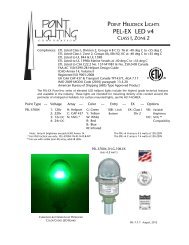
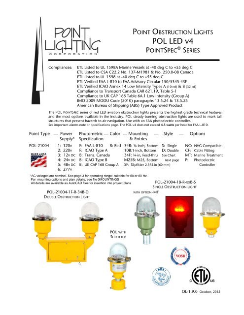
<strong>POL</strong>-21004-1F-R-34B-D<br />
DOUBLE OBSTRUCTION LIGHT<br />
<strong>POL</strong> WITH<br />
SLIPFITTER<br />
WITH OPTION -MT<br />
See Chart MT: Marine Treatment<br />
4: 24v DC B: ICAO Type B M25B: M25, Bottom next page P: Photoelectric<br />
5: 48v DC B: UK CAP 168 Group A SF: Slipfitter 2.375-in (60 mm) Controller<br />
6: 277v<br />
*AC voltages are nominal. See page 3 for operating range; suitable for 50 or 60 Hz.<br />
For mounting options and plan details, see file 0MOUNTINGS<br />
All details are available as AutoCAD files for insertion into project plans<br />
POINT OBSTRUCTION LIGHTS<br />
<strong>POL</strong> <strong>LED</strong> v4<br />
POINTSPEC ® SERIES<br />
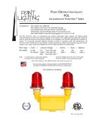
Compliances: ETL Listed to UL 1598A Marine Vessels at -40 deg C to +55 deg C<br />
ETL Listed to CSA C22.2 No. 137-M1981 & No. 250.0-08 Canada<br />
ETL Listed to UL 1598 at -40 deg C to +55 deg C<br />
ETL Verified FAA L-810 to FAA Advisory Circular 150/5345-43F<br />
ETL Verified ICAO Annex 14 Low Intensity Types A (10 cd) & B (32 cd)<br />
Compliance to Transport Canada CAR 621.19, Table 5-1<br />
Compliance to UK CAP 168 Table 6A.1 Low Intensity (Group A)<br />
IMO 2009 MODU Code (2010) paragraphs 13.5.24 & 13.5.25<br />
American Bureau of Shipping (ABS) Type Approved Product<br />
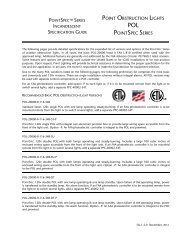
The <strong>POL</strong> POINTSPEC series of red <strong>LED</strong> aviation obstruction lights presents the highest grade technical features<br />
and the most options available in the industry. <strong>POL</strong> steady-burning obstruction lights are used to mark tall<br />
structures that present hazards to air navigation. Use with an FAA photoelectric controller.<br />
See important alarms note on specifications page. The <strong>POL</strong> v4 does not exceed 4.5 watts per head for FAA L-810.<br />
<strong>POL</strong>-21004-1B-R-xxB-S<br />
SINGLE OBSTRUCTION LIGHT<br />
OL-1.9.0 October, 2012
SELECTION CHART<br />
Style Transfer Alarm Alarm Pilot Flashing Description<br />
Non-Isolated Isolated Light<br />
-S � � Standard Single<br />
-S1 � � � Single: flashing (no junction box)<br />
-S1.3 � � � Single with junction box: flashing (Note 1)<br />
-S2 � � � Single: non-isolated alarm (Note 1)<br />
-S2.1 � � � DC only; same as Style –S2 for use with POC<br />
-S3 � � � Single: integral junction box & cover (Note 1)<br />
-S4 � � � Single: isolated failure alarm (Note 1)<br />
-S5 � ���<br />
Dual Mode Single: flashing, but may be set in the field<br />
to be steady-burning<br />
-D Double: both heads operating<br />
-DT � Double: operating head & standby with transfer<br />
-D1 � � Double: transfer & pilot light<br />
-D2 � � Double: transfer & non-isolated alarm (Note 2)<br />
-D2.2 �<br />
Double: both heads operating &<br />
non-isolated alarm<br />
-D3 � � � Double: transfer, non-isolated alarm & pilot light<br />
-D4 � � Double: transfer & isolated alarm (Note 2)<br />
-D4.2 � Double: both heads operating & isolated alarm<br />
-D5 � � � Same as Style –D4 with pilot light (Note 2)<br />
-D6 � � Same as Style –D4 prewired with six (6) wires<br />
-D7 � Double: both heads flashing<br />
-D8 � �<br />
Double: primary head flashes and transfer to standby<br />
head which flashes; no alarm<br />
-D10 � � � Same as Style –D8 with alarm line<br />
-D13 � �<br />
Double: transfer, primary head alarm, standby head<br />
alarm & power failure alarm; tagged wires<br />
-D14 � � Double: both heads flashing with isolated alarm<br />
-D15 � � Double: both heads flashing; non-isolated alarm<br />
-D16 � � �<br />
-D18 � �<br />
-D19 � � �<br />
POINT OBSTRUCTION LIGHTS<br />
<strong>POL</strong> <strong>LED</strong> v4<br />
POINTSPEC ® SERIES<br />
Double: primary head flashes and transfer to standby<br />
head flashes; pilot light on transfer<br />
Double: transfer, primary head alarm, standby head<br />
alarm; non-isolated alarms<br />
Double: primary head flashes and transfer to standby<br />
head flashes; with isolated alarm line<br />
Note 1: This single has a J-box & cover below the <strong>LED</strong> head assembly; box is required for any single with option –P.<br />
Note 2: Alarm activates on transfer
TECHNICAL NOTES & OPTIONS<br />
Alarm options must be selected at time of initial order. Alarms cannot be added in the field or retrofitted.<br />
<strong>POL</strong> <strong>LED</strong> lights cannot be monitored by 3rd party systems or controllers without selecting an alarm version<br />
of the <strong>POL</strong> <strong>LED</strong>.<br />
The <strong>POL</strong> optical subassembly is factory sealed to prevent moisture penetration and it is not serviceable.<br />
Option –MT: Marine Treatment<br />
The fixture shall be treated for marine conditions by cleaning per US MIL method III of TT-C-490, chromate<br />
priming per US MIL-C-5541, epoxy powder base coat and glossy polyester powdercoat finish coat in color RAL<br />
6003 (FED-STD-595 color #14097) green. Oven cured per US MIL-PRF-24712A.<br />
Option –NC: NVG Compatible<br />
Adds infrared <strong>LED</strong> to allow visibility to pilots with or without night vision goggles.<br />
Option –P: Photoelectric Control see Detail OL06 in file 0MOUNTINGS<br />
Adds a prewired FAA PEC to single with junction box or double.<br />
Option –FF: Floor Flange Mounting see Details OL19 & OL20 in file 0MOUNTINGS<br />
For use with photoelectric controller option –P. Cover mounted 3-position switch ON-OFF-AUTO. Requires a<br />
double or single with junction box. For remote override switch, add item PL40110-3.<br />
Option –CF[C]: Cable Fitting – For single with junction box or double<br />
Through holes with 1.5-inch long ¼-20 hex head stainless steel screws and sealing washers. Cable compression<br />
fitting for outside diameter: 0.5 to 0.625-inch (12.7 to 15.9-mm).<br />
Option –BKT: Bracket for Wall Mounting see Detail OL17 in file 0MOUNTINGS<br />
Simple aluminum bracket for single or double. Screw holes for the structure to be drilled in the field.<br />
Option –OS: Override Switch<br />
For use with photoelectric controller option –P. Cover mounted 3-position switch ON-OFF-AUTO. Requires a<br />
double or single with junction box. For remote override switch, add item PL40110-3.<br />
POWER CONSUMPTION<br />
PER <strong>POL</strong> <strong>LED</strong> LIGHT HEAD<br />
POINT OBSTRUCTION LIGHTS<br />
<strong>POL</strong> <strong>LED</strong> v4<br />
POINTSPEC ® SERIES<br />
Code Type Voltage Frequency Watts* mA VA*<br />
-1F FAA & ICAO A 120 AC 50/60 Hz 3.5 42 5.0<br />
-2F FAA & ICAO A 220 AC 50/60 Hz 4.2 26 5.9<br />
-3F FAA & ICAO A 12 DC --- 3.4 280 3.4<br />
-4F FAA & ICAO A 24 DC --- 3.5 144 3.5<br />
-5F FAA & ICAO A 48 DC --- 3.0 63 3.0<br />
-6F FAA & ICAO A 277 AC 50/60 Hz 4.1 25 7.1<br />
-1B ICAO B & TRAN CAN 120 AC 50/60 Hz 6.9 63 7.6<br />
-2B ICAO B & TRAN CAN 220 AC 50/60 Hz 6.9 34 7.4<br />
-3B ICAO B & TRAN CAN 12 DC --- 4.3 470 4.3<br />
-4B ICAO B & TRAN CAN 24 DC --- 4.3 230 4.3<br />
-5B ICAO B & TRAN CAN 48 DC --- 5.0 104 5.0<br />
-6B ICAO B & TRAN CAN 277 AC 50/60 Hz 6.9 28 7.9<br />
Note: For option –NC, add 1.0 watts (1.1 VA)<br />
*Power consumption for AC units includes the effect of the unit’s power factor which accounts for the<br />
difference between watts and volt-amperes. Measurements were made at the nominal AC voltages.<br />
The operating range for 120v units: 93 - 144v; for 220v units: 176 - 250v; for 277v units: 263 -291v.
<strong>POL</strong> <strong>LED</strong> SPECIFICATIONS<br />
SPECIFICATIONS COMMON TO ALL <strong>POL</strong> <strong>LED</strong> VERSIONS<br />
The red <strong>LED</strong> lighted (specify: voltage) aviation obstruction light shall be tested and certified FAA L-810 (ICAO low intensity Type B). The<br />
obstruction light shall operate properly at 50 or 60 Hz at an input voltage supply of 120V +/-20% (93V to 144V) or, for 220V units, 176V<br />
to 250V or, for 277V units, +/-5% (263V to 291V). Within the preceding ranges, the output to the <strong>LED</strong> board shall be a controlled,<br />
stabilized constant current. The obstruction light shall not exceed 4.5 watts per head for FAA L-810.<br />
The AC obstruction lights shall be listed Suitable for Use in Wet Locations to UL1598A Marine Vessels, UL1598 2nd Edition Luminaries;<br />
CSA C22.2 No. 250.0-04, 2nd Edition; UL50 11th Edition Standard for Enclosures for Electrical Equipment and CSA C22.2 No. 94-M91<br />
Special Purpose Enclosures. Sealed to IP66 ingress protection.<br />
Special Technical Note*: DC light fixtures shall be reverse polarity protected.<br />
* Competitors’ units will fail if installed with reverse polarity.<br />
The unit shall have passed the FAA certification tests: the constant high temperature test to +130 deg F (+55 deg C) and the constant low<br />
temperature test to -67 deg F (-55 deg C) conducted in accordance with US MILSTD-810F, Method 501.4, Procedure II; the wind-blown<br />
rain test conducted in accordance with US MIL-STD-810E, Method 506.3, Procedure I; and the humidity test shall be in accordance with<br />
US MIL-STD-810E, Method 507.3, Procedure I. The complete test regime shall exceed the requirements of NEMA 4X and IP 65. The light<br />
head shall be powdercoat painted aviation yellow for corrosion resistance certified by the manufacturer to comply with the US Military<br />
Standard Salt Fog Test conducted per MIL-STD-810F, Method 509.4, Procedure I, paragraph 4.5.2..<br />
The clear lens shall be strong soda lime glass with the wave-length matched to the <strong>LED</strong>s to permit the fullest light transmission. The lens<br />
shall be smooth and rounded to reduce the adhesion of dirt, ice and snow.<br />
The red emitting <strong>LED</strong>s shall meet the chromaticity requirements of US MIL-C-25050. The high output <strong>LED</strong>s shall not exceed five (5) in<br />
number and shall be the latest technology providing uniform light output over the range required by the governing standard. The <strong>LED</strong><br />
average life shall exceed 100,000 hours.<br />
The <strong>LED</strong>s shall be soldered in a factory set position to insure consistent light output. Wire mounted raised <strong>LED</strong>s that can be bent out of<br />
position shall be unacceptable and cause for rejection. The <strong>LED</strong> board shall be treated with a protective dielectric conformal coating for<br />
protection from moisture and corrosion.<br />
The power supply board shall include short circuit and open circuit protection and the unit shall be protected from line surges by metal<br />
oxide varistors (MOVs). All v4 units shall have the power supply and flasher board (if any) potted in the fixture (head subassembly)<br />
casting. There shall be a clear design element for the dissipation of <strong>LED</strong> heat to insure the <strong>LED</strong>s do not fail prematurely.<br />
The double <strong>LED</strong> light unit shall have an integral cast aluminum junction box with a minimum of 100 cubic inches of enclosed wiring<br />
space accessible from the front of the light unit. The wiring access cover shall be gasketed to be watertight, shall have captive screws and<br />
shall be secured to the unit with a tether. The cover tether and all hardware shall be stainless steel.<br />
The red <strong>LED</strong> aviation obstruction light shall be POINTSPEC Series <strong>POL</strong>-21004 manufactured by <strong>Point</strong> <strong>Lighting</strong> <strong>Corporation</strong>.<br />
Important Note: Alarm options must be selected at time of initial order. Alarms cannot be added in the field or retrofitted.<br />
<strong>POL</strong> <strong>LED</strong> lights cannot be monitored by 3rd party systems or controllers without selecting an alarm version of the <strong>POL</strong> <strong>LED</strong>.<br />
WEIGHT, DIMENSIONS & SHIPPING DATA<br />
POINT OBSTRUCTION LIGHTS<br />
<strong>POL</strong> <strong>LED</strong> v4<br />
POINTSPEC ® SERIES<br />
inches (mm) Multi-Pack Carton<br />
Weight Height Width Depth Qty Weight Dim (inches)<br />
POINTSPEC Single: 3.8 lbs 1.7 kg 8.6 (217) 6.0 (152) 5.0 (127) 12 47 lbs 21.3 kg 22 x 15 x 17<br />
POINTSPEC Double: 12.4 lbs 5.6 kg 13.3 (337) 14.9 (378) 5.0 (127) 2 27 lbs 12.3 kg 19 x 19 x 19<br />
Wind Loading: Effective Projected Area (EPA) for POINTSPEC Double 0.69 square feet<br />
P O I N T L I G H T I N G C O R P O R A T I O N<br />
Mail: P.O. Box 686, Simsbury, CT 06070 Plant: West Dudley Town Rd, Bloomfield, CT<br />
Tel 01 860.243.0600 USA Fax 01 860.243.0665<br />
email: Info@<strong>Point</strong><strong>Lighting</strong>.com website: www.<strong>Point</strong><strong>Lighting</strong>.com