Logix 3000 Series - Flowserve Corporation
Logix 3000 Series - Flowserve Corporation
Logix 3000 Series - Flowserve Corporation

You also want an ePaper? Increase the reach of your titles
YUMPU automatically turns print PDFs into web optimized ePapers that Google loves.
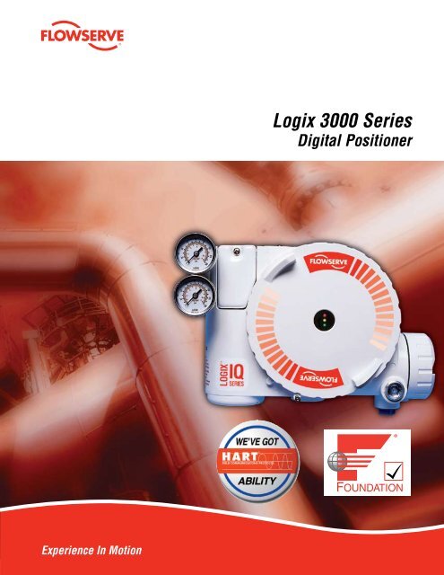
Experience In Motion<br />
<strong>Logix</strong> <strong>3000</strong> <strong>Series</strong><br />
Digital Positioner
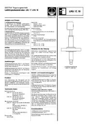
The <strong>Logix</strong> 3400IQ offers local setup<br />
and calibration in seconds... easy as 1, , 3<br />
With the 3400IQ, function blocks are no longer<br />
required to set up, configure and perform a simple<br />
stroke calibration. The 3400IQ can be set up with<br />
9-32 VDC supply and 45 psi (min.) air supply on any<br />
valve/actuator platform.<br />
When the 3400IQ is in OOS (Out Of Service mode), the local<br />
interface shown to the right is accessible and setup can be<br />
carried out through the following steps:<br />
1. Make sure the mechanical linkage, air tubing and actuator<br />
mounting are correct.<br />
2. Set the configuration switches to the desired operation of<br />
the valve/actuator.<br />
3. Set the quick calibration switch to Jog or Auto. In Jog,<br />
the 100% position can be manually adjusted using the<br />
yellow up and down buttons after Re-Cal is pressed. In Auto,<br />
the positioner finds the 100% position and calibration is<br />
complete. LED blink codes will guide the user through the<br />
process. Four green blinks (GGGG) or (GGGY) at the end of<br />
the sequence confirm that the calibration was successful.<br />
4. If needed, the GAIN switch located to the right of the<br />
jog buttons will speed up or slow down the positioner’s<br />
GAIN<br />
H<br />
A B<br />
G C<br />
F D<br />
E<br />
response to command changes.<br />
With the Auto Tune configuration<br />
switch set to “On”, the positioner’s<br />
algorithm will select a gain with no<br />
over-shoot. The ‘E” position of the<br />
rotary GAIN dial indicates “neutral”<br />
with respect to gain adjustment.<br />
Turning clockwise from E to H and<br />
will speed up the response. Tuning counter-clockwise from<br />
E will slow it down, with A being the slowest response.<br />
Calibration, configuration and tuning parameters from<br />
the local interface will be automatically updated in the<br />
Transducer Block on the <strong>Logix</strong> 3400IQ. Local setup and<br />
calibration that does not require a link to a host controller,<br />
PC or hand-held device, as well as local validation that setup<br />
is correct, make any Foundation Fieldbus installation easy<br />
and straightforward.
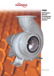
The <strong>Logix</strong> 3 00IQ – no software or hand-held device<br />
required... easy as 1, , 3<br />
The <strong>Logix</strong> 3200IQ can be set up with 10 VDC milliamp<br />
current supply current and 45 psi (min.) air supply on<br />
any valve/actuator platform.<br />
With the <strong>Logix</strong> 3200IQ, the local interface shown to the<br />
right can be used to set up the unit in seconds through the<br />
following steps:<br />
1. Make sure the mechanical linkage, air tubing and actuator<br />
mounting are correct.<br />
2. Set the configuration switches to the desired operation of<br />
the valve/actuator.<br />
3. Set the quick calibration switch to Jog or Auto. In Jog,<br />
100% position can be manually adjusted using the yellow<br />
up and down buttons after Re-Cal is pressed. In Auto,<br />
the positioner finds the 100% position and calibration is<br />
complete. LED blink codes will guide the user through the<br />
process. Four green blinks (GGGG) or (GGGY) at the end of<br />
the sequence confirm that the calibration was successful.<br />
4. If needed, the GAIN switch located to the right of the<br />
jog buttons will speed up or slow down the positioner’s<br />
response to command changes.<br />
GAIN<br />
H<br />
A B<br />
G C<br />
F D<br />
E<br />
With the Auto Tune configuration<br />
switch set to “On”, the positioner’s<br />
algorithm will select a gain with no<br />
over-shoot. The ‘E” position of the<br />
rotary GAIN dial indicates “neutral”<br />
with respect to gain adjustment.<br />
Turning clockwise from E to H and<br />
will speed up the response. Tuning counter-clockwise from<br />
E will slow it down, with A being the slowest response.<br />
Calibration, configuration and tuning parameters from the<br />
local interface will be automatically updated in the HART<br />
registers on the <strong>Logix</strong> 3200IQ. Local setup and calibration<br />
that does not require a link to a host controller, PC or handheld<br />
device, and local validation that setup is correct make<br />
any HART installation easy and straightforward.<br />
flowserve.com<br />
3
4<br />
The <strong>Logix</strong> 3400IQ for Foundation Fieldbus Applications<br />
Complete local configuration, on any valve/actuator and local.<br />
FF Simulate – Run a control strategy without process<br />
FF Write Protect – Locks out unauthorized writes to NVRAM<br />
36 status and<br />
alert and messages<br />
displayed locally via<br />
three easy-to-read<br />
LEDs<br />
<strong>Logix</strong> 3400IQ Features<br />
RFI/EMI Immunity ¸<br />
FISCO Compliant, User Interface ¸<br />
Polarity Insensitive UI (Potted UI) ¸<br />
PID Block (6 Honeywell PID Equations) ¸<br />
LAS (Link Master Device) ¸<br />
Auto Tune (Positioner Performance) ¸<br />
High Friction Stability ¸<br />
FF Code Download ¸<br />
Flash Ram (Local Positioner Embedded Code Upgrade) ¸<br />
Local Valve Signature Storage ¸<br />
Local Calibration and Setup (While in OOS) ¸<br />
24/7 Local Fault Monitoring ¸<br />
Local Adjustable Gain ¸<br />
Wizard/Method for On-line Commissioning ¸<br />
Local Jog Buttons to Adjust 100% Command Position<br />
(While in OOS)<br />
Fast Function Block Execution Time ¸<br />
Linkable Position feedback (AO Read Back) ¸<br />
Multiple View Objects in Transducer Block ¸<br />
Honeywell PKS Partner with Signature Acquisition Tool<br />
and <strong>Flowserve</strong> Scout<br />
Three Response Curves (Linear, =% and Custom)<br />
Locally Activated, or Through FF<br />
¸<br />
¸<br />
¸<br />
<strong>Flowserve</strong> is a Honeywell<br />
Partner, with <strong>Flowserve</strong><br />
Scout and Signature<br />
Acquisition Tool integrated<br />
in the ExperionDCS Asset<br />
Manager<br />
Foundation Fieldbus made easy.<br />
(In OOS) Calibrate stroke and<br />
adjust tuning without entering the<br />
Transducer Block —Updates the<br />
Block when complete.<br />
Valve Signature with <strong>Logix</strong> 3400IQ from Honeywell Experion.
The <strong>Logix</strong> 3 00IQ for HART Applications<br />
Complete local configuration, just like the <strong>Logix</strong> 3400IQ, but HART protocol<br />
• Local status and alert messages<br />
• Tuning (Auto Tune function and manual adjustment)<br />
• Jog buttons to manually adjust 100% position<br />
• Easy-to-install 4-20 mA analog feedback card option<br />
Simple plug-in AO card, automatically zero and spans position feedback during Quick Cal<br />
<strong>Logix</strong> 3200IQ Features<br />
RFI/EMI Immunity ¸<br />
Auto Tune (Positioner Performance) ¸<br />
High Friction Stability Tuning ¸<br />
Integral 4-20 mA Feedback Option ¸<br />
Flash RAM (Local Positioner Embedded Code<br />
Upgrade)<br />
Local Valve Signature Storage ¸<br />
Local Calibration and Setup ¸<br />
24/7 Local Fault Monitoring ¸<br />
Local Adjustable Gain ¸<br />
Three Response Curves (Linear, =% and custom) ¸<br />
Local Jog Buttons to Adjust 100% Command Position ¸<br />
Valve Signature Diag. “Valve Analysis” AMS<br />
SnapOn ® Application<br />
AMS Device Manager ¸<br />
Honeywell PKS Partner with Honeywell HART FDM ¸<br />
¸<br />
¸<br />
ValveAnalysis friction plot-signature running inside AMS<br />
Device Manager<br />
The <strong>Logix</strong> 3200IQ positioner is<br />
AMS aware and is included in<br />
AMS Device Manager.<br />
flowserve.com
There’s a <strong>Flowserve</strong> Expert Inside<br />
We’ve taken the guesswork out of setting up and calibrating<br />
positioners by building our expert knowledge into every <strong>3000</strong><br />
series positioner. Simply start the calibration process by<br />
pushing a button, and the “brain on board” takes over. Even<br />
tuning is as easy as turning a knob, making the positioner more<br />
or less responsive to signal changes—and when complete, the<br />
positioner gives you a “thumbs up” that it’s ready to go.<br />
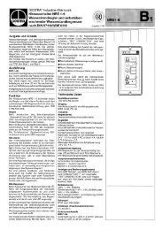
Whether it is mounted on one of the world-renowned heritage<br />
brand valves from <strong>Flowserve</strong>, or any other OEM valve/<br />
actuator platform, when you select a <strong>3000</strong> series positioner,<br />
the <strong>Flowserve</strong> expert comes with it—at no extra charge.<br />
A <strong>Logix</strong> <strong>3000</strong> <strong>Series</strong> mounted to a Kinetrol Size 14 Rotary<br />
vane actuator.<br />
A <strong>Logix</strong> <strong>3000</strong> <strong>Series</strong> mounted on a Valtek Mark One
Time is Money<br />
Up and running, making money faster with the <strong>3000</strong> series<br />
<strong>Logix</strong><br />
<strong>3000</strong><br />
<strong>Series</strong><br />
BONUS<br />
Other digital<br />
positioners<br />
<strong>3000</strong> <strong>Series</strong> Facts<br />
3400<br />
Plant commission schedule<br />
Time to Startup and Commission<br />
• Two versions: Basic & Advanced (Advanced includes<br />
pressure sensors to measure actuator pressure and<br />
calculate supply pressure)<br />
• ITK - CFF 4.51, 4.6<br />
• DD Version 0601 FB Code Version 2.04.23<br />
• DD available at www.fieldbus.org or www.flowserve.com<br />
• Stores a valve signature onboard in NVRAM<br />
• Onboard temperature sensor to measure local positioner<br />
ambient<br />
• Stroke speed limiter (configurable in transducer block)<br />
• Stainless steel version available<br />
3 00<br />
• Two versions: Basic & Advanced (Advanced includes<br />
pressure sensors to measure actuator pressure)<br />
• HART Command 1, 3, 9, 33 & 48<br />
• Burst Mode available to continuously transmit<br />
• Position command analog loop current<br />
• Final value of command after characterization<br />
• Supply pressure (advanced), Temperature (basic)<br />
• Stem position in percent<br />
• Onboard temperature sensor to measure local positioner<br />
ambient<br />
• Stroke speed limiter (configurable through HART)<br />
• Stainless steel version available<br />
• Enhanced Device Description for advanced signature<br />
diagnostics<br />
• Step test, friction test, HRL, data logger<br />
flowserve.com
<strong>Logix</strong> 3400 Positioner Overview<br />
The <strong>Logix</strong> 3400IQ digital positioner is a two-wire Foundation<br />
Fieldbus registered, LinkMaster (LAS) digital valve<br />
positioner. The positioner is configurable through the local<br />
user interface. The <strong>Logix</strong> 3400IQ utilizes the FF protocol to<br />
allow two-way remote communications with the positioner.<br />
Figure 1: System Positioning Algorithm for <strong>Logix</strong> 3400IQ Digital Positioners<br />
FOUNDATION<br />
Fieldbus<br />
Signal<br />
Command In<br />
(AO Block)<br />
Specifications<br />
Table I: Electrical Specifications<br />
Power Supply<br />
Two-wire, 9-32 VDC<br />
FF compatible<br />
IS Fisco compliant<br />
Communications FF Protocol ITK 4.6x<br />
Operating Current 23 mA<br />
Maximum Voltage 36.0 VDC<br />
Table II: Environmental Conditions<br />
Operating Temperature<br />
Range<br />
Transport and Storage<br />
Temperature Range<br />
Standard<br />
-40° to 176°F<br />
(-40° to 80°C)<br />
-40° to 176°F (-40° to 80°C)<br />
Operating Humidity 0 - 100% non-condensing<br />
Note: The air supply must conform to ISA Standard ISA 7.0.01 (a<br />
dew point at least 18 degrees Fahrenheit below ambient temperature,<br />
particle size below five microns—one micron recommended—and<br />
oil content not to exceed one part per million).<br />
Table III: Physical Specifications<br />
Housing<br />
Material<br />
Cast, powder-painted aluminum or stainless steel<br />
Soft Goods Buna-N / Florosilicone<br />
Weight<br />
FOUNDATION<br />
Fieldbus<br />
Transducer<br />
Block<br />
Linear Mode<br />
Characterization<br />
Soft Limits<br />
MPC<br />
CONTROL<br />
COMMAND<br />
8.3 pounds (3.9 kg) aluminum<br />
20.5 pounds (9.3 kg) stainless steel<br />
+<br />
-<br />
Deviation<br />
Control<br />
Algorithm<br />
Pmax<br />
Pmin<br />
Gmult<br />
Integration<br />
Summer<br />
I<br />
Inner<br />
Loop<br />
Offset<br />
The <strong>Logix</strong> 3400IQ positioner can control both double- and<br />
single-acting actuators with linear or rotary mountings. The<br />
positioner is completely powered by the FF signal. Start up<br />
voltage must be at least 9 V.<br />
+<br />
+<br />
+<br />
D/A<br />
Output<br />
Percentage<br />
Table IV: Positioner Specifications<br />
Deadband
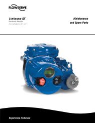
<strong>Logix</strong> 3 00 Positioner Overview<br />
The <strong>Logix</strong> 3200IQ digital positioner is a two-wire 4-20 mA<br />
input digital valve positioner. The positioner is configurable<br />
through the local user interface. The <strong>Logix</strong> 3200IQ utilizes<br />
the HART protocol to allow two-way remote communications<br />
with the positioner. The <strong>Logix</strong> 3200IQ positioner can control<br />
Figure 1: <strong>Logix</strong> <strong>3000</strong> <strong>Series</strong><br />
Digital Positioners Schematic<br />
(air-to-open configuration)<br />
Specifications<br />
Table I: Electrical Specifications<br />
Power Supply<br />
Two-wire, 4-20 mA<br />
10.0 to 30.0 VDC<br />
Compliance Voltage 10.0 VDC @ 20 mA<br />
Effective Resistance<br />
495 Ω @ 20 mA Typical<br />
Communications HART Protocol<br />
Minimum Operating<br />
Current<br />
Maximum Voltage 30.0 VDC<br />
O<br />
Stem<br />
Position<br />
Sensor<br />
Add 20 Ω when HART communication<br />
active<br />
3.6 mA without AO board<br />
3.7 mA with AO board<br />
Table II: Environmental Conditions<br />
Operating Temperature<br />
Range<br />
Transport and Storage<br />
Temperature Range<br />
Standard<br />
Low<br />
-4° to 176°F<br />
FF/HART<br />
Input Signal<br />
(-20° to 80°C)<br />
-40° to 176°F<br />
(-40° to 80°C)<br />
-40° to 176°F (-40° to 80°C)<br />
Operating Humidity 0 - 100% non-condensing<br />
Exhaust<br />
Hall Effect<br />
Sensor<br />
Piezo Valve<br />
Note: The air supply must conform to ISA Standard ISA 7.0.01<br />
(a dew point at least 18 degrees Fahrenheit below ambient<br />
temperature, particle size below five microns—one micron recommended—and<br />
oil content not to exceed one part per million).<br />
Flame<br />
Arrestor<br />
both double- and single-acting actuators with linear or<br />
rotary mountings. The positioner is completely powered by<br />
the 4-20 mA input signal. Start up current must be at least<br />
3.6 mA without AO card or 3.85 mA with AO card.<br />
Spool Valve<br />
Output 2<br />
Output 1<br />
Flame<br />
Arrestor<br />
Pressure<br />
Sensor Board<br />
Air Supply<br />
Main PCB<br />
Table III: Physical Specifications<br />
Housing<br />
Material<br />
Flame<br />
Arrestor<br />
Filter<br />
Digital Position Algorithm<br />
Regulator<br />
LED<br />
Display<br />
Cast, powder-painted aluminum or stainless steel<br />
Soft Goods Buna-N / Florosilicone<br />
Weight<br />
8.3 pounds (3.9 kg) aluminum<br />
20.5 pounds (9.3 kg) stainless steel<br />
Table IV: Positioner Specifications<br />
Deadband
10<br />
<strong>3000</strong> <strong>Series</strong> dimensions<br />
NOTE: Dimensions in inches (mm)<br />
��������������������<br />
��������������<br />
���������������<br />
����<br />
��������<br />
����<br />
�������<br />
������������������<br />
���������������������<br />
��������������<br />
����<br />
�������<br />
����<br />
������<br />
����<br />
��������<br />
�����<br />
��������<br />
����<br />
��������<br />
����<br />
������<br />
����<br />
�������<br />
����<br />
�������<br />
����<br />
�������<br />
����<br />
�������<br />
����<br />
��������<br />
����<br />
�������<br />
������<br />
����<br />
�������<br />
����<br />
�������<br />
����������������������<br />
���������������<br />
��������������<br />
����<br />
��������<br />
����<br />
�������<br />
������������<br />
��������������������������<br />
��������������<br />
����������<br />
���������<br />
����������<br />
�����
How to order<br />
2<br />
Selection Code<br />
3<br />
Protocol<br />
HART<br />
Foundation Fieldbus<br />
2<br />
4<br />
Diagnostics<br />
Material<br />
Certifications<br />
Shaft<br />
Conduit Connections<br />
Action<br />
1 0<br />
Standard Diagnostics 0<br />
Advanced Diagnostics 1<br />
Aluminum, White Paint (Valtek) 0<br />
Stainless Steel, No paint (Valtek) 1<br />
3200 3400<br />
Explosion proof Class I, Div 1, Groups B,C,D FM/CSA) ¸ 01<br />
Explosion proof EEx d IIB + H2 ATEX II 2 GD (CENELEC) ¸ 07<br />
Explosion proof Class I, Div 1, Groups B,C,D Intrinsically Safe<br />
Class I, Div 1,<br />
Groups A thru G (FM, CSA) FM Nonincendive. CSA Class I, Div 2<br />
Group IIB + H2 and Exia Class 1, Zone 0, Group IIC<br />
(CSA ONLY)<br />
¸ 10<br />
General Purpose ¸ ¸ 14<br />
Intrinsically Safe EEx ia IIC T4/T5, Standard Temp: -20ºC<<br />
=Ta
FCD LGENBR<strong>3000</strong>-00 Printed in USA.<br />
To find your local <strong>Flowserve</strong> representative:<br />
For more information about <strong>Flowserve</strong> <strong>Corporation</strong>, visit<br />
www.flowserve.com or call USA 1 800 225 6989<br />
<strong>Flowserve</strong> <strong>Corporation</strong> has established industry leadership in the design and manufacture of its products. When properly selected, this <strong>Flowserve</strong> product is designed to perform its<br />
intended function safely during its useful life. However, the purchaser or user of <strong>Flowserve</strong> products should be aware that <strong>Flowserve</strong> products might be used in numerous applications<br />
under a wide variety of industrial service conditions. Although <strong>Flowserve</strong> can (and often does) provide general guidelines, it cannot provide specific data and warnings for all possible<br />
applications. The purchaser/user must therefore assume the ultimate responsibility for the proper sizing and selection, installation, operation, and maintenance of <strong>Flowserve</strong> products.<br />
The purchaser/user should read and understand the Installation Operation Maintenance (IOM) instructions included with the product, and train its employees and contractors in the safe<br />
use of <strong>Flowserve</strong> products in connection with the specific application.<br />
While the information and specifications contained in this literature are believed to be accurate, they are supplied for informative purposes only and should not be considered certified or<br />
as a guarantee of satisfactory results by reliance thereon. Nothing contained herein is to be construed as a warranty or guarantee, express or implied, regarding any matter with respect<br />
to this product. Because <strong>Flowserve</strong> is continually improving and upgrading its product design, the specifications, dimensions and information contained herein are subject to change<br />
without notice. Should any question arise concerning these provisions, the purchaser/user should contact <strong>Flowserve</strong> <strong>Corporation</strong> at any one of its worldwide operations or offices.<br />
© 2006 <strong>Flowserve</strong> <strong>Corporation</strong>, Irving, Texas, USA. <strong>Flowserve</strong> is a registered trademark of <strong>Flowserve</strong> <strong>Corporation</strong>.<br />
flowserve.com<br />
United States<br />
<strong>Flowserve</strong> <strong>Corporation</strong><br />
Flow Control<br />
1350 N. Mt. Springs Parkway<br />
Springville, UT 84663<br />
Phone: 801-489-8611<br />
Fax: 801-489-3719<br />
Australia<br />
14 Dalmore Drive<br />
Scoresby, Victoria<br />
Melbourne, Australia 3179<br />
Phone: 61-3-9759-3300<br />
Facsimile: 61-3-9759-3301<br />
Austria<br />
Kasernengasse 6, A-9500 Villach<br />
Phone: +31 181 330040<br />
Fax: +43 4242 41181 50<br />
E-mail: schmidt@flowserve.com<br />
China<br />
<strong>Flowserve</strong> China<br />
Unit 05-08, 10F Azia Center<br />
No. 1233 Lujiazui Ring Road<br />
Shanghai 200120, PRC<br />
Phone: +86-21-6146-1100<br />
Fax: +86-21-5047-6288<br />
India<br />
Plot #4, EPIP, Whitefield<br />
Karnataka<br />
Bangalore 560 066<br />
India<br />
Phone: +91 80-28412866<br />
Fax: +91 80-28412868<br />
Netherlands<br />
Van Leeuwenhoekweg 6<br />
HELLEVOETSLUIS<br />
3225 LX<br />
Netherlands<br />
Phone: +31 181 330047<br />
Fax: +31 181 330040<br />
Singapore<br />
<strong>Flowserve</strong> Singapore<br />
12 Tuas Avenue 20<br />
Singapore 638824<br />
Phone: +65 862 3332<br />
Fax: +65 862 4940