AK-42309-500 Positive Positioner Pneumatic Relay ... - fidemar
AK-42309-500 Positive Positioner Pneumatic Relay ... - fidemar
AK-42309-500 Positive Positioner Pneumatic Relay ... - fidemar

You also want an ePaper? Increase the reach of your titles
YUMPU automatically turns print PDFs into web optimized ePapers that Google loves.
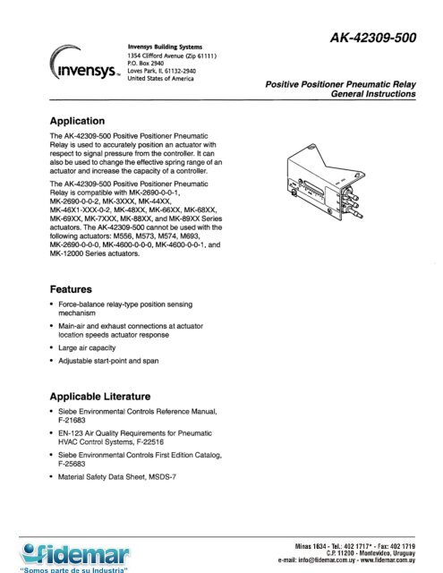
Application<br />
lnvensys Building Systems<br />
1354 Clifford Avenue (Zip 61111)<br />
P.O. Box 2940<br />
Loves Park, IL 61132-2940<br />
United States of America<br />
The <strong>AK</strong>-<strong>42309</strong>-<strong>500</strong> <strong>Positive</strong> <strong>Positioner</strong> <strong>Pneumatic</strong><br />
<strong>Relay</strong> is used to accurately position an actuator with<br />
respect to signal pressure from the controller. It can<br />
also be used to change the effective spring range of an<br />
actuator and increase the capacity of a controller.<br />
The <strong>AK</strong>-<strong>42309</strong>-<strong>500</strong> <strong>Positive</strong> <strong>Positioner</strong> <strong>Pneumatic</strong><br />
<strong>Relay</strong> is compatible with MK-2690-0-0-1,<br />
MK-2690-0-0-2, MK-3XxX, MK-44Xx,<br />
MK-46X1 -XxX-O-2, MK-48Xx, MK-66Xx, MK-68Xx,<br />
MK-69Xx, MK-7XXX, MK-88Xx, and MK-89XX Series<br />
actuators. The <strong>AK</strong>-<strong>42309</strong>-<strong>500</strong> cannot be used with the<br />
following actuators: M556, M573, M574, M693,<br />
MK-2690-0-0-0, MK-4600-0-0-0, MK-4600-0-0-1, and<br />
MK-12000 Series actuators.<br />
Features<br />
Force-balance relay-type position sensing<br />
mechanism<br />
Main-air and exhaust connections at actuator<br />
location speeds actuator response<br />
Large air capacity<br />
Adjustable start-point and span<br />
Applicable Literature<br />
Siebe Environmental Controls Reference Manual,<br />
F-21 683<br />
EN-l 23 Air Quality Requirements for <strong>Pneumatic</strong><br />
HVAC Control Systems, F-2251 6<br />
Siebe Environmental Controls First Edition Catalog,<br />
F-25683<br />
Material Safety Data Sheet, MSDS-7<br />
A K-<strong>42309</strong>-<strong>500</strong><br />
<strong>Positive</strong> <strong>Positioner</strong> <strong>Pneumatic</strong> <strong>Relay</strong><br />
General lnstructionb<br />
Printed in U.S.A. 11-98 F-22909-6
Action: Direct (increase in output pressure to actuator with an increase in pilot pressure<br />
from controller).<br />
Pilot input: 0 to main air pressure, psig.<br />
Output: 0 to main air pressure, psig.<br />
Construction:<br />
Housing, Polysulfone.<br />
Diaphragm, Neoprene.<br />
Start Point: Adjustable 1 to 12 psig (7 to 83 kPa).<br />
Span: Adjustable 2 to 13 psig (14 to 90 kPa); factory set at 5 psig.<br />
Supply Air: Clean, oil free, dry air required (refer to EN-123, F-22516).<br />
Maximum Pressure, 30 psig (207 kPa).<br />
Nominal Supply Pressure, 15 to 20 psig (103 to 138 kPa).<br />
Environment:<br />
Ambient Temperature Limits,<br />
Shipping: -40 to 160°F (-40 to 71 “C).<br />
Operating: 32 to 140°F (0 to 60°C).<br />
Humidity, 5 to 95% R.H., non-condensing.<br />
Locations, NEMA Type 1.<br />
Air Connection Code: See Figure-l.<br />
Air connections:<br />
“M” and “B,” Barbed for l/4 in. (6 mm) O.D. plastic tubing.<br />
“P,” Dual-contoured for l/4 in. (6 mm) O.D. and 5/32 in. 4 mm) O.D. tubing.<br />
Air Consumption for Sizing Air Compressor: 0.011 scfm (5.2 ml/s) at 20 psig (138 kPa)<br />
SUPPlY.<br />
Air Capacity for Sizing Air Mains: 20 scim (5.5mV.s).<br />
Flow Capacity: 860 scim (235 ml/s) at 20 psig (138 kPa) supply.<br />
Mounting Linkage: All necessary linkage provided to mount the <strong>AK</strong>-<strong>42309</strong>-<strong>500</strong> <strong>Positive</strong><br />
<strong>Positioner</strong> to MK-2690-0-0-1, MK-2690-0-0-2, MK-3XxX, MK-44Xx, MK-46X1-XxX-0-2,<br />
MK-48Xx, MK-66XX, MK-68Xx, MK-69Xx, MK-7XxX, MK-88Xx, and MK-89XX series<br />
actuators.<br />
Dimensions: 2-l/2 H x 4-l/2 W x 3 D in. (64 x 114 x 76 mm). See Figure-12.<br />
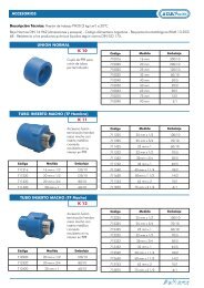
ACCESSORIES<br />
TOOL-951 <strong>Pneumatic</strong> calibration tool kit.
TYPICAL APPLICATIONS (piping diagram)<br />
INSTALLATION<br />
Inspection<br />
Requirements<br />
Precautions<br />
<strong>AK</strong>-<strong>42309</strong>-<strong>500</strong><br />
Figure-l Piping Connections.<br />
Inspect the package for damage. If damaged, notify the appropriate carrier immediately.<br />
If undamaged, open the package and inspect the device for obvious damage. Return<br />
damaged products.<br />
� Piping diagrams<br />
� Linkage kit (provided with the <strong>AK</strong>-<strong>42309</strong>-<strong>500</strong> <strong>Positive</strong> <strong>Positioner</strong>)<br />
� Tools (not provided):<br />
- l/4” (6 mm) maximum single blade screwdriver for start point lock and span<br />
adjustment lock<br />
- Appropriate socket wrenches for mounting bracket to the actuator.<br />
- Needle nose pliers for bending feedback spring<br />
- Tubings and fittings (not provided)<br />
� Training: Installer must be a qualified, experienced technician.<br />
General<br />
Caution:<br />
� Make all connections in accordance with the piping diagram.<br />
� Do not exceed the ratinos of the device(s).<br />
Main Air Supply<br />
Caution:<br />
� Particles in the main air supply larger than 0.03 microns will adversely affect the<br />
reliability and life of the relay unit. A refrigerated air dryer, particulate filter, and<br />
coalescing filter will provide a quality air supply (refer to EN-l 23, F-2251 6).<br />
� Oil, dirt, and water in the main air supply will cause unwarranted damage to the positive<br />
positioner and void the warranty.<br />
� Compressor oil must be mineral base. Synthetic base oils will destroy pneumatic<br />
controls and void the warranty.<br />
Location Caution: Do not locate unit in areas subject to excessive vibration or corrosive<br />
atmospheres.<br />
3
Mounting Suggested Mounting Sequence<br />
� MK-2690-0-0-1, MK-2690-0-0-2, MK-46X1 -XxX-O-2, and MK-48XX actuators can be<br />
mounted to the valve before the <strong>AK</strong>-<strong>42309</strong><strong>500</strong> <strong>Positive</strong> <strong>Positioner</strong> is mounted to the<br />
actuator.<br />
� The MK-66Xx, MK-68Xx, MK-69Xx, MK-88Xx, and MK-89XX series actuators can be<br />
mounted to the valve before the <strong>AK</strong>-<strong>42309</strong><strong>500</strong> <strong>Positive</strong> <strong>Positioner</strong> is mounted to the<br />
actuator, but the valve linkage must be disconnected in order to install the feedback arm<br />
and the indication disc.<br />
� When mounting the <strong>AK</strong>-<strong>42309</strong>-<strong>500</strong> <strong>Positive</strong> <strong>Positioner</strong> to the MK-3XXX and MK-7XXX<br />
series actuators, mount the positive positioner to the actuator and install the positive<br />
positioner’s feedback arm on the actuator before mounting the actuator to the damper.<br />
Mounting the <strong>AK</strong>-<strong>42309</strong>-<strong>500</strong> <strong>Positive</strong> <strong>Positioner</strong> to Actuators<br />
MK-2690-0-0-l and MK-2690-O-0-2<br />
(Figure-2)<br />
Mount the <strong>AK</strong>-<strong>42309</strong>-<strong>500</strong> to the MK-2690-0-O-(1, 2) actuator as follows:<br />
1. Line up positive positioner mounting bracket holes with the mounting holes on the<br />
actuator cover (Figure-2).<br />
2. Assemble with the two (2) short mounting screws and tighten.<br />
3. Select the appropriate spring and feedback arm from the linkage kit (Table-l). Balance<br />
of parts may be discarded or retained for spares.<br />
MK-3XXX, MK-44Xx, MK-46X1-XxX-O-2, and MK-48XX<br />
(Figure-3, Figure-4, and Figure-6)<br />
Mount the <strong>AK</strong>-<strong>42309</strong>-<strong>500</strong> to the MK-3XxX, MK-44Xx, MK-46X1-XxX-O-2, and MK-48XX<br />
actuators as follows:<br />
1. Remove referenced cover screws and discard.<br />
Note: All older MK-3XXX actuators which do not have flat pads around mounting screw<br />
locations require spacers from the linkage kit provided with the <strong>AK</strong>-<strong>42309</strong>-<strong>500</strong> <strong>Positive</strong><br />
<strong>Positioner</strong>.<br />
2. Line up positive positioner mounting bracket holes with actuator cover screw holes<br />
shown in Figure-3, Figure-4, and Figure-6.<br />
3. Reassemble with specified screws (included with the <strong>AK</strong>-<strong>42309</strong>-<strong>500</strong>) through positive<br />
positioner mounting bracket holes and tighten.<br />
4. Select the appropriate spring and feedback arm from the linkage kit (Table-l). Balance<br />
of parts may be discarded or retained for spares.<br />
MK66XX, MK-68XX, MK-69Xx, MK-7XxX, MK-88Xx, and MK-89XX<br />
(Figure-7, Figure-8, and Figure-g)<br />
Mount the <strong>AK</strong>-<strong>42309</strong>-<strong>500</strong> to the MK-66Xx, MK-68Xx, MK-69Xx, MK-7XxX, MK-88Xx, and<br />
MK-89XX series actuators as follows:<br />
Remove actuator cover screws and set aside.<br />
Line up positive positioner mounting bracket holes with actuator cover screw holes.<br />
(See Figure-7, Figure-8, or Figure-g.)<br />
Reassemble with actuator cover screws through positive positioner mounting bracket<br />
holes and tighten.<br />
Select the appropriate spring and feedback arm from the linkage kit provided with the<br />
<strong>AK</strong>-<strong>42309</strong>-<strong>500</strong> <strong>Positive</strong> <strong>Positioner</strong> (Table-l). Balance of parts from the linkage kit may<br />
be discarded or retained for spares.
Installing the Feedback Arm<br />
MK-2690-0-0-1, MK-2690-O-0-2, MK-44Xx, MK-46X1 -XxX-O-2, and MK-48XX<br />
(Figure-2, Figure-5, and Figure-6)<br />
Install the feedback arm on the <strong>AK</strong>-<strong>42309</strong>-<strong>500</strong> <strong>Positive</strong> <strong>Positioner</strong> as follows:<br />
1. Consult Table-l to select appropriate feedback arm.<br />
2. Push the feedback arm firmly into the hole provided in the diaphragm piston with the<br />
hook rotated 45” to 90” from the final position.<br />
3. Lock the arm into the diaphragm piston by twisting the arm into position with a<br />
downward force.<br />
MK-SXXX, MK-66Xx, MK-68Xx, MK-69Xx, MK-7XXX, MK-88Xx, and MK-89XX<br />
(Figure-3, Figure-7, Figure-8, and Figure-O)<br />
To install, secure the feedback arm to the valve stem or actuator output shaft.<br />
Installing the Feedback Spring<br />
Install the feedback spring as follows:<br />
1. Choose the appropriate feedback spring from the linkage kit provided with the<br />
<strong>AK</strong>-<strong>42309</strong>-<strong>500</strong> <strong>Positive</strong> <strong>Positioner</strong>.<br />
2. Move the <strong>AK</strong>-<strong>42309</strong>-<strong>500</strong> Start Point lever (Figure-lo) to the “Lo” position (required to<br />
position the feedback lever).<br />
3. Position the span adjustment slider to align the spring hook mounting hole to the scale<br />
below (required to set the operating span of the actuator).<br />
4. Line up the feedback arm and span adjustment slider.<br />
5. Insert hooked end of feedback spring into the back of the hole on the span adjustment<br />
slider (Figure-lo).<br />
6. Cut off feedback spring l/2 to 3/4” (13 to 19 mm) beyond the end of the feedback arm.<br />
7. Form bend, approximately l/4” (6 mm) from the free end of the feedback spring to allow<br />
approximately l/32 to l/l 6” (0.8 to 1.6 mm) tension at the feedback arm.<br />
Caution: Do not put a sharp bend in the feedback spring. More than l/16” (1.6 mm) of<br />
tension on the spring may prevent adjustment to low start points.<br />
8. Connect the bent end of the feedback spring to the feedback arm.<br />
5
Table-l Actuator and Valve Compatibility with <strong>AK</strong>-<strong>42309</strong>-<strong>500</strong> <strong>Positive</strong> <strong>Positioner</strong> Feedback Arm.<br />
6<br />
:eedback Spring Dimensions<br />
Where<br />
Used,<br />
valve size in<br />
Actuator inches<br />
(metric<br />
equivalent<br />
in mm)<br />
WK-2690-0-O-l and<br />
UK-2690-0-0-2a<br />
WK-3XxX Dampers<br />
VIK-44xX Dampers<br />
1 + “A t+<br />
-TT<br />
Factory Set<br />
Actuator Dimension “A”<br />
Feedback<br />
Arm<br />
Dimension<br />
Stroke<br />
in. (mm)<br />
in. (mm)<br />
“B”<br />
in. (mm)<br />
Feedback Arm<br />
Mounting<br />
Hole<br />
Diameter<br />
in. (mm)<br />
VB-7XXX<br />
and<br />
VB-9XxX,<br />
l/2 to l-114<br />
7/16 (11) 11/16 (17) 5/l 6 (8)<br />
(15 to 50) m N.A.<br />
For actuator<br />
strokes less than<br />
3-l/2 (89) 3 (7gb,<br />
Adjustable l-1/8 (29).<br />
2 to 4 For strokes<br />
(51 to 102) 3 to 4b<br />
(76 to 102), l-5/8<br />
(Z)<br />
(41).<br />
11/16 (17)<br />
l-3/32 (28) 7/16 (11)<br />
w<br />
21/64 (8)<br />
T N.A*<br />
VB-7XxX,<br />
112 to 2<br />
(15 to 50)<br />
\rlK-46X1 -XXX-O-2a and 7/16 (11) 11/16 (17) 5/l 6 (8)<br />
VB-9XxX,<br />
l/2 to l-114 T N.A.<br />
(15 to32)<br />
\rlK-48XXd<br />
UK-66XX<br />
WK-68XX<br />
VIK-69XX<br />
VIK-7XXX<br />
VB-9XxX,<br />
l-112 to 2 29/32 (23) l-3/32 (28) 7/16 (11)<br />
(40 to 50)<br />
T N’A.<br />
VB-7XxX,<br />
l/2 to 2<br />
(15 to 50)<br />
7/16 (11) 11/16 (17)<br />
I<br />
N.A.<br />
VB-SXXX,<br />
l-1/2 to 4<br />
(40 to 80)<br />
29/32 (23) l-3/32 (28) 7/16(11)<br />
y<br />
I ~<br />
VB-9XxX,<br />
5 and 6 l-27/32 (46) l-1/8 (29) . .<br />
(none)<br />
Dampers<br />
4-l/2 (114)<br />
Adjustable<br />
4 to 5<br />
(102 to 127)<br />
VIK-88XX<br />
VB-9XxX,<br />
2-l/2 to 4<br />
(65 to 80)<br />
29132 (23) l-3/32 (28) 7/16 (11)<br />
VIK-89XX<br />
VB-9XxX,<br />
5 and 6<br />
(none)<br />
l-27/32 (46) 1 -l/8 (29) 11/16 (17)<br />
2-l/4 (57)b 33:4A(13)<br />
a <strong>AK</strong>-<strong>42309</strong>-<strong>500</strong> cannot be mounted on MK-2690-0-0-0, MK-4600-0-O-(0,1), or MK-12000 series actuators.<br />
b See page 10 for Span Slider Setting Instructions.<br />
c Linkage is factory set at 2” (51 mm). Linkage is adjustable from l/2 to 3” (13 to 76mm).<br />
d The MK-46XX actuator series is offered for retrofit on obsolete VB-9XxX valves. This actuator cannot be used with VB-7XXX valves.<br />
v<br />
I-$<br />
I<br />
I<br />
N.A.<br />
N.A.<br />
N.A.
Piping Before installing tubing, see Figure-2 through Figure-9 for proper alignment and refer to the<br />
piping diagram and an example of typical piping (Figure-l and Figure-l 1). Install tubing as<br />
follows:<br />
1. Install l/8 MNPT x l/4” (3.2 x 6mm) barb fitting into air connection on actuator.<br />
Note: Barb fitting provided with MK-8XXX only.<br />
2. Connect l/4” O.D. (6mm) plastic tubing between fitting in actuator and “B” port on the<br />
positive positioner.<br />
3. Connect main air supply to “M” port.<br />
4. Connect controller output (variable air signal) to “P” port.<br />
Feedback Spring<br />
Two (2) Short Replacement<br />
Mounting Screws (from kit)<br />
I<br />
t<br />
l/4” O.D. Plastic Tube<br />
(Not Provided)<br />
+-- MK-2690-0-0-1 or<br />
MK-2690-0-0-2 Act1 Jator<br />
Hole for Feedback<br />
Arm in Piston<br />
Figure-2 MK-2690-0-0-1 and MK-2690-0-0-2.<br />
l/8” MNPT x l/4”<br />
barb elbow (field l/4” O.D. plastic tube<br />
(field supplied)<br />
supp’ie\d) /<br />
Actutat<br />
top<br />
Two (2) long<br />
replacement<br />
screws (from kit)<br />
Spacers (2) (from kit)<br />
(required on models \<br />
without the pads) <strong>AK</strong>-<strong>42309</strong>-<strong>500</strong><br />
Figure-3 MK9XXX<br />
FeLdback<br />
spring<br />
Feedback<br />
arm
Two (2) long replacement screws<br />
Two<br />
<strong>AK</strong>-<strong>42309</strong>-<strong>500</strong><br />
Feedback arm<br />
(2) long replacement<br />
(from kit)<br />
<strong>AK</strong>-<strong>42309</strong>-<strong>500</strong>-<br />
Feedback spring<br />
Two I (2) long replacement SC<br />
<strong>AK</strong>-<strong>42309</strong>-<strong>500</strong>-<br />
Feedback spring<br />
Feedback arm<br />
l/8 MNPT x l/4” barb<br />
(not provided)<br />
Figure-4 MK-44XX.<br />
l/8 MNPT x l/4” barb<br />
Figure-5 MK-46X1 -XXX-O-2 Series<br />
l/8 MNPT x 114” barb<br />
Figure-6 MK-48XX Series.<br />
l/4” O.D. plastic tube<br />
Hole for feedback<br />
” O.D.<br />
plastic tube<br />
- MK-46X1 -XXX-O-2<br />
Actuator<br />
Hole for feedback<br />
” O.D. plastic tube<br />
- MK-48XX Series<br />
Actuator<br />
ole for feedback
Use existing actuator<br />
cover screws (2)<br />
<strong>AK</strong>-<strong>42309</strong>-<strong>500</strong> -<br />
l/8 MNPT x 114” barb<br />
l/4” O.D. plastic tube<br />
(not provided)<br />
Feedback spring K-66Xx, MK-68Xx, and MK-69XX<br />
- Series Actuator<br />
Stem extension lock nut Valve position indicator disc<br />
Figure-7 MK-66Xx, MK-68Xx, and MK-69XX Series<br />
l/8 MNPTx l/4”<br />
(field supplied)<br />
MK-7XXX<br />
Series<br />
Figure-8 MK-7XXX Series.
IO<br />
Use existing actuate<br />
cover screws (2)<br />
<strong>AK</strong>-<strong>42309</strong>-<strong>500</strong>---c<br />
Feedback spring<br />
Figure-9 MK-88XX and MK-89XX Series.<br />
MK-88XX and MK-89XX<br />
Series Actuator
Setup Start Point (Figure-l 0 and Figure-l 1)<br />
Start point is the pressure at which the actuator shaft just begins to extend. Start point must<br />
be adjusted after any span slider setting. Adjust the start point as follows:<br />
1. Connect main air supply to “M” port and a variable air signal to “P” port.<br />
2. Adjust variable air signal on “P” port to desired start point pressure.<br />
3. Loosen start point lever lock screw.<br />
4. Adjust lever until actuator just starts to extend.<br />
5. Tighten lock screw.<br />
6. Remove variable air signal from “P” port and connect to controller output.<br />
Span Slider Setting (Figure-10 and Figure-l 1)<br />
Span is the pilot pressure change required to produce a full actuator stroke. The span can<br />
be changed by repositioning the span adjustment slider.<br />
MK-2690-0-0-1, MK-2690-0-0-2, MK-44Xx, MK-46X1 -XxX-O-2, MK-48Xx, MK-66XX, MK-<br />
68Xx, MK-69XX, MK-88XX, MK-89XX<br />
1. Determine the span required.<br />
2. Set the span adjustment slider.<br />
M K-3XxX and M K-7xXx<br />
The MKSXXX and MK--/XXX series actuators have adjustable strokes. The adjustable<br />
stroke requires the span adjustment slider setting to be calculated for the <strong>AK</strong>-<strong>42309</strong>-<strong>500</strong><br />
<strong>Positive</strong> <strong>Positioner</strong>.<br />
1. Determine the required actuator stroke.<br />
2. Determine the span required.<br />
3. Calculate the span adjustment slider position (SASP) as follows:<br />
� MK-3XXX with stroke less than 3” (76 mm)<br />
Span X 2<br />
Actuator-Stroke<br />
= SASP<br />
� MKSXXX with stroke 3 to 4” (76 to 102 mm)<br />
� MK-7XXX<br />
Span X 3<br />
ActuatorStroke<br />
Span X 4<br />
ActuatorStroke<br />
Example: MK-3XXX<br />
Span = 8 psi (55 kPa)<br />
= SASP<br />
= SASP<br />
Actuator Stroke = 3-l/2” (89 mm)<br />
SASP = 8x3 = 6.9<br />
3.5<br />
4. Set span adjustment slider to the calculated position.<br />
11
MAINTENANCE<br />
FIELD REPAIR<br />
DIMENSIONAL DATA<br />
Main<br />
Air<br />
Start Point Lever<br />
Figure-l 0 <strong>AK</strong>-<strong>42309</strong>-<strong>500</strong> Adjustments.<br />
Test<br />
Gauge<br />
Pilot<br />
Main Air<br />
*Indicates span adjustment<br />
slider positlon<br />
Main<br />
Air<br />
AL-481<br />
Pressure <strong>AK</strong>-<strong>42309</strong>-<strong>500</strong><br />
Regulator <strong>Positive</strong> <strong>Positioner</strong><br />
Figure-l 1 Typical Adjustment Piping.<br />
To<br />
*Actuator<br />
Regular maintenance of the total system is recommended to assure sustained optimum<br />
performance.<br />
None. Replace an inoperative positive positioner with a functional unit.<br />
Figure-l 2 <strong>AK</strong>-<strong>42309</strong>-<strong>500</strong> Dimensions.<br />
F-22909-6 BK Specifications may change as design improvements are introduced. Printed in U.S.A.