

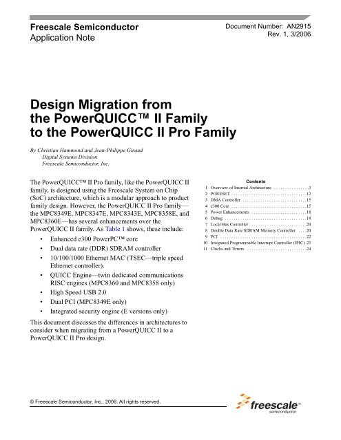
Design Migration from the PowerQUICC II Family to - Freescale ...
Design Migration from the PowerQUICC II Family to - Freescale ...
Design Migration from the PowerQUICC II Family to - Freescale ...

Create successful ePaper yourself
Turn your PDF publications into a flip-book with our unique Google optimized e-Paper software.
<strong>Freescale</strong> Semiconduc<strong>to</strong>r<br />
Application Note<br />
<strong>Design</strong> <strong>Migration</strong> <strong>from</strong><br />
<strong>the</strong> <strong>PowerQUICC</strong> <strong>II</strong> <strong>Family</strong><br />
<strong>to</strong> <strong>the</strong> <strong>PowerQUICC</strong> <strong>II</strong> Pro <strong>Family</strong><br />
By Christian Hammond and Jean-Philippe Giraud<br />
Digital Systems Division<br />
<strong>Freescale</strong> Semiconduc<strong>to</strong>r, Inc.<br />
The <strong>PowerQUICC</strong> <strong>II</strong> Pro family, like <strong>the</strong> <strong>PowerQUICC</strong> <strong>II</strong><br />
family, is designed using <strong>the</strong> <strong>Freescale</strong> System on Chip<br />
(SoC) architecture, which is a modular approach <strong>to</strong> product<br />
family design. However, <strong>the</strong> <strong>PowerQUICC</strong> <strong>II</strong> Pro family—<br />
<strong>the</strong> MPC8349E, MPC8347E, MPC8343E, MPC8358E, and<br />
MPC8360E—has several enhancements over <strong>the</strong><br />
<strong>PowerQUICC</strong> <strong>II</strong> family. As Table 1 shows, <strong>the</strong>se include:<br />
Enhanced e300 PowerPC core<br />
Dual data rate (DDR) SDRAM controller<br />
10/100/1000 E<strong>the</strong>rnet MAC (TSEC—triple speed<br />
E<strong>the</strong>rnet controller).<br />
QUICC Engine—twin dedicated communications<br />
RISC engines (MPC8360 and MPC8358 only)<br />
High Speed USB 2.0<br />
Dual PCI (MPC8349E only)<br />
Integrated security engine (E versions only)<br />
This document discusses <strong>the</strong> differences in architectures <strong>to</strong><br />
consider when migrating <strong>from</strong> a <strong>PowerQUICC</strong> <strong>II</strong> <strong>to</strong> a<br />
<strong>PowerQUICC</strong> <strong>II</strong> Pro design.<br />
© <strong>Freescale</strong> Semiconduc<strong>to</strong>r, Inc., 2006. All rights reserved.<br />
Document Number: AN2915<br />
Rev. 1, 3/2006<br />
Contents<br />
1 Overview of Internal Architecture . . . . . . . . . . . . . . . .3<br />
2 PORESET . . . . . . . . . . . . . . . . . . . . . . . . . . . . . . . . . .12<br />
3 DMA Controller . . . . . . . . . . . . . . . . . . . . . . . . . . . . .15<br />
4 e300 Core . . . . . . . . . . . . . . . . . . . . . . . . . . . . . . . . . .15<br />
5 Power Enhancements . . . . . . . . . . . . . . . . . . . . . . . . .18<br />
6 Debug . . . . . . . . . . . . . . . . . . . . . . . . . . . . . . . . . . . . .18<br />
7 Local Bus Controller . . . . . . . . . . . . . . . . . . . . . . . . . .20<br />
8 Double Data Rate SDRAM Memory Controller . . . .20<br />
9 PCI . . . . . . . . . . . . . . . . . . . . . . . . . . . . . . . . . . . . . . .22<br />
10 Integrated Programmable Interrupt Controller (IPIC) 23<br />
11 Clocks and Timers . . . . . . . . . . . . . . . . . . . . . . . . . . .24
Table 1. Feature Set Differences across <strong>the</strong> <strong>PowerQUICC</strong> <strong>II</strong> and <strong>PowerQUICC</strong> <strong>II</strong> Pro Families<br />
<strong>Family</strong> <strong>PowerQUICC</strong> <strong>II</strong> <strong>PowerQUICC</strong> <strong>II</strong> Pro <strong>Family</strong><br />
Device MPC8280 MPC8349/E MPC8347/E MCP8343/E MCP8358/E MCP8360/E<br />
Core G2LE e300 e300 e300 e300 e300<br />
CPU Speed<br />
Communication<br />
Processor<br />
Speed<br />
Up <strong>to</strong> 450MHz Up <strong>to</strong> 667MHz* Up <strong>to</strong> 667MHz 1<br />
(TBGA)<br />
Up <strong>to</strong> 400MHz<br />
(PBGA)<br />
Up <strong>to</strong> 400MHz Up <strong>to</strong> 400MHz Up <strong>to</strong> 667MHz*<br />
333MHz N/A N/A N/A 400MHz 400MHz<br />
L1 I/D Cache 16KI/16KD 32KI/32KD 32KI/32KD 32KI/32KD 32KI/32KD 32KI/32KD<br />
Memory<br />
Controller<br />
64/32 bit<br />
SDRAM<br />
64/32 bit DDR 64/32 bit DDR 32 bit DDR 32 bit DDR 1x64 -2x32 bit<br />
DDR<br />
Local Bus Yes Yes Yes Yes Yes Yes<br />
PCI<br />
E<strong>the</strong>rnet<br />
USB<br />
Security<br />
1 32-bit up <strong>to</strong> 66<br />
MHz<br />
2 32-bit up <strong>to</strong> 66<br />
MHz or<br />
1 64-bit up <strong>to</strong><br />
66MHz<br />
1 32-bit up <strong>to</strong><br />
66 MHz<br />
1 32-bit up <strong>to</strong><br />
66 MHz<br />
3-10/100 2-10/100/1000 2-10/100/1000 2-10/100/1000<br />
(M<strong>II</strong>, RGM<strong>II</strong> &<br />
RTBI only)<br />
Hi-speed host,<br />
device<br />
Hi-speed host,<br />
device, and<br />
OTG<br />
No SEC 2.0<br />
(E version only)<br />
Hi-speed host,<br />
device, and<br />
OTG<br />
SEC 2.0<br />
(E version only)<br />
Hi-speed host,<br />
device, and<br />
OTG<br />
SEC 2.0<br />
(E version only)<br />
1 32-bit up <strong>to</strong><br />
66 MHz<br />
2-10/100/1000<br />
(M<strong>II</strong>, RGM<strong>II</strong> &<br />
RTBI only)<br />
Full-speed<br />
host, device,<br />
SEC 2.0<br />
(E version only)<br />
Interrupt<br />
Controller<br />
Yes PIC-compliant PIC-compliant PIC-compliant PIC-compliant PIC-compliant<br />
1<br />
e300 667 MHz core on Revision 1.1 onward.<br />
The <strong>PowerQUICC</strong> <strong>II</strong> Pro family comprises several devices <strong>to</strong> benefit <strong>the</strong> general-purpose, industrial, and<br />
network infrastructure markets. As Figure 1 and Figure 2 show, <strong>the</strong>re are two main <strong>PowerQUICC</strong> <strong>II</strong> Pro<br />
family architectures—<strong>the</strong> MPC834x and <strong>the</strong> MPC835x/6x.<br />
NOTE<br />
Not all <strong>the</strong> blocks are supported on each <strong>PowerQUICC</strong> <strong>II</strong> Pro device. Refer<br />
<strong>to</strong> <strong>the</strong> relevant device reference manual for details.<br />
<strong>Design</strong> <strong>Migration</strong> <strong>from</strong> <strong>the</strong> <strong>PowerQUICC</strong> <strong>II</strong> <strong>Family</strong> <strong>to</strong> <strong>the</strong> <strong>PowerQUICC</strong> <strong>II</strong> Pro <strong>Family</strong>, Rev. 1<br />
1 32-bit up <strong>to</strong><br />
66 MHz<br />
2-10/100/1000<br />
(M<strong>II</strong>, RGM<strong>II</strong> &<br />
RTBI only)<br />
Full-speed<br />
host, device<br />
SEC 2.0<br />
(E version only)<br />
UART Yes Dual Dual Dual Dual Dual<br />
I 2 C Single Dual Dual Dual Dual Dual<br />
SPI Yes Yes Yes Yes Yes Yes<br />
2 <strong>Freescale</strong> Semiconduc<strong>to</strong>r
CSB<br />
Arbiter<br />
&<br />
Bus<br />
Moni<strong>to</strong>r<br />
Security<br />
DMA PCI<br />
CSB<br />
Arbiter<br />
&<br />
Bus<br />
Moni<strong>to</strong>r<br />
PCI<br />
Security<br />
DMA PCI<br />
DUART<br />
Dual I 2 C<br />
Timers<br />
GPIO<br />
SPI<br />
DUART<br />
Dual I 2 C<br />
Timers<br />
GPIO<br />
CSB<br />
64-bits<br />
Interrupt<br />
Controller<br />
USB 2.0 Hi-Speed<br />
Host Device<br />
CSB<br />
64-bits<br />
e300 Core<br />
32KB<br />
D-Cache<br />
Figure 1. MPC834xE<br />
32KB<br />
I-Cache<br />
Figure 2. MPC8358E/MPC8360E<br />
1 Overview of Internal Architecture<br />
•<br />
Interrupt<br />
Controller<br />
8xTDM<br />
Ports<br />
32-bit<br />
RISC CP<br />
8x10/100<br />
E<strong>the</strong>rnet<br />
e300 Core<br />
32KB<br />
D-Cache<br />
10/100/1000<br />
E<strong>the</strong>rnet<br />
32KB<br />
I-Cache<br />
QUICC Engine<br />
2x10/100/1000<br />
E<strong>the</strong>rnet<br />
Local Bus<br />
Local Bus<br />
32-bit<br />
RISC CP<br />
Overview of Internal Architecture<br />
DDR1<br />
Controller<br />
10/100/1000<br />
E<strong>the</strong>rnet<br />
DDR1<br />
Controller<br />
2xUTOPIA/POS<br />
(124 MPHY)<br />
Figure 3 and Figure 4 show <strong>the</strong> differences in <strong>the</strong> internal device architecture between <strong>the</strong> <strong>PowerQUICC</strong> <strong>II</strong><br />
and <strong>PowerQUICC</strong> <strong>II</strong> Pro families. Note that <strong>the</strong> bus architecture shown is a <strong>the</strong>oretical summary of <strong>the</strong><br />
<strong>PowerQUICC</strong> <strong>II</strong> Pro’s capability. For fur<strong>the</strong>r details regarding <strong>the</strong> <strong>PowerQUICC</strong> <strong>II</strong> family bus<br />
architecture, refer <strong>to</strong> MPC8260 Dual-Bus Architecture and Performance Considerations (AN2335). For<br />
details on <strong>the</strong> architecture of a <strong>PowerQUICC</strong> <strong>II</strong> Pro device, refer <strong>to</strong> <strong>the</strong> device reference manual.<br />
<strong>Design</strong> <strong>Migration</strong> <strong>from</strong> <strong>the</strong> <strong>PowerQUICC</strong> <strong>II</strong> <strong>Family</strong> <strong>to</strong> <strong>the</strong> <strong>PowerQUICC</strong> <strong>II</strong> Pro <strong>Family</strong>, Rev. 1<br />
<strong>Freescale</strong> Semiconduc<strong>to</strong>r 3
Overview of Internal Architecture<br />
G2 Core<br />
with MMU<br />
16KB Instruction<br />
L1 Cache,<br />
16KB Data<br />
L1 Cache<br />
SDMA<br />
CPM<br />
Coherent System Bus<br />
(CSB)<br />
(64-bit bus up <strong>to</strong> 333MHz)<br />
TSEC<br />
QE (*)<br />
60x Arbiter<br />
60x <strong>to</strong> Local Bus<br />
Bridge<br />
60x Bus<br />
(64-bits – 100MHz)<br />
Address<br />
Decode<br />
Register<br />
Local Bus<br />
(32-bits – 100MHz)<br />
Figure 3. MPC82xx <strong>PowerQUICC</strong> <strong>II</strong> Architecture<br />
e300 Core with MMU<br />
32KB Instruction L1 Cache<br />
32KB Data L1 Cache<br />
SEQ<br />
I 2 C<br />
DMA PCI<br />
DUART<br />
Local Bus<br />
Controller<br />
Figure 4. MPC83xx<strong>PowerQUICC</strong> <strong>II</strong> Pro Architecture<br />
60x Bus<br />
Memory Controller<br />
Local Bus<br />
Memory Controller<br />
DDR<br />
Controller<br />
1x32-bits – 133MHz<br />
(*) QE can be directly connected <strong>to</strong> a<br />
DDR Interface with no CSB access<br />
1x32/64-bits –<br />
333MHz Data Rate<br />
or<br />
2x32-bits –<br />
333MHz Data Rate<br />
The <strong>PowerQUICC</strong> <strong>II</strong> dual-bus architecture is optimized for CPM accesses <strong>to</strong> <strong>the</strong> local bus (direct access)<br />
and <strong>the</strong> G2 core accesses (or ano<strong>the</strong>r 60x bus master) via <strong>the</strong> 60x bus. With this configuration, both<br />
transactions can be carried out simultaneously. However, this architecture has <strong>the</strong> following limitations:<br />
No burst access capability on <strong>the</strong> local bus for CPU/60x bus master.<br />
Local bus memory area is not cacheable (due <strong>to</strong> <strong>the</strong> lack of burst capability).<br />
A strong dependency between <strong>the</strong> CPU/CPM/local bus/60x bus clock frequencies.<br />
As Figure 4 shows, <strong>the</strong> <strong>PowerQUICC</strong> <strong>II</strong> Pro internal bus architecture is built around <strong>the</strong> coherent system<br />
bus (CSB). Within <strong>the</strong> CSB architecture, <strong>the</strong> CSB arbiter and bus moni<strong>to</strong>r unit manages transactions<br />
between all <strong>the</strong> possible CSB masters (e300 core, QUICC Engine, TSECs, PCI external masters, DMA<br />
…and so on) and targets (PCI, local bus, DDR controller). The CSB arbiter and bus moni<strong>to</strong>r unit is<br />
responsible for:<br />
Bus transaction arbitration<br />
Transaction address mapping management<br />
Transaction coherency management<br />
<strong>Design</strong> <strong>Migration</strong> <strong>from</strong> <strong>the</strong> <strong>PowerQUICC</strong> <strong>II</strong> <strong>Family</strong> <strong>to</strong> <strong>the</strong> <strong>PowerQUICC</strong> <strong>II</strong> Pro <strong>Family</strong>, Rev. 1<br />
4 <strong>Freescale</strong> Semiconduc<strong>to</strong>r
1.1 Bus Transaction Arbitration<br />
Overview of Internal Architecture<br />
The CSB carries <strong>the</strong> transactions between most of <strong>the</strong> possible masters and <strong>the</strong> targets, except for <strong>the</strong><br />
QUICC Engine, which has direct access <strong>to</strong> secondary DDR (MPC835x/6x only). As a shared resource, an<br />
arbitration mechanism must manage access <strong>to</strong> this bus. This arbitration is provided by <strong>the</strong> CSB arbiter and<br />
bus moni<strong>to</strong>r unit. The management unit provides each CSB master with its own set of internal signals <strong>to</strong><br />
request and <strong>to</strong> get access <strong>to</strong> <strong>the</strong> CSB. Figure 5 shows <strong>the</strong> CSB master arbitration signals.<br />
BR<br />
REPEAT<br />
Master PRIORITY[0:1]<br />
BG<br />
Arbiter<br />
Figure 5. CSB Master Arbitration Signals<br />
Before starting a transaction, a CSB master must be granted <strong>the</strong> bus. To request bus ownership a master<br />
asserts its bus request (BR) signal along with <strong>the</strong> arbitration signals REPEAT and PRIORITY[0:1]. The<br />
bus arbiter later asserts <strong>the</strong> corresponding bus grant (BG) signal <strong>to</strong> <strong>the</strong> requesting master depending on <strong>the</strong><br />
system state and arbitration mechanism. When BG is asserted <strong>to</strong> <strong>the</strong> requesting master, <strong>the</strong> transaction can<br />
begin. The current bus master can transfer 1 <strong>to</strong> 8 bytes per transaction.<br />
A priority level (0–3) is assigned <strong>to</strong> all possible bus masters. The arbitration mechanism follows <strong>the</strong>se<br />
rules:<br />
For each priority level, a fair arbitration scheme is used (round-robin scheme).<br />
For priority levels 1, 2 and 3, a place holder is reserved for lower-level arbitration rings.<br />
Each master can change its priority level at any time <strong>to</strong> provide a determinist latency.<br />
Figure 6 shows <strong>the</strong> CSB mastership algorithm. Some MPC83xx peripherals, such as <strong>the</strong> TSECs can<br />
change <strong>the</strong>ir normal priority level <strong>to</strong> <strong>the</strong> highest level when moving <strong>to</strong> emergency mode. For example, if<br />
a TSEC receive FIFO reaches a programmable threshold, an emergency mode is au<strong>to</strong>matically triggered<br />
so <strong>the</strong> TSEC can get access <strong>to</strong> <strong>the</strong> CSB as quickly as possible, allowing <strong>the</strong> data <strong>to</strong> be passed <strong>to</strong> system<br />
memory (DDR, local bus). This avoids an overrun situation. This feature contributes <strong>to</strong> system stability in<br />
a peak load condition. As <strong>the</strong> TSEC receive FIFO recovers <strong>to</strong> a normal level (threshold), <strong>the</strong> TSEC<br />
recovers its normal priority level.<br />
<strong>Design</strong> <strong>Migration</strong> <strong>from</strong> <strong>the</strong> <strong>PowerQUICC</strong> <strong>II</strong> <strong>Family</strong> <strong>to</strong> <strong>the</strong> <strong>PowerQUICC</strong> <strong>II</strong> Pro <strong>Family</strong>, Rev. 1<br />
<strong>Freescale</strong> Semiconduc<strong>to</strong>r 5
Overview of Internal Architecture<br />
M1 M2<br />
Figure 6. Coherent System Bus Master-Ship Algorithm<br />
1.2 Additional Coherent System Bus (CSB) Features<br />
To ensure a high level of performance <strong>from</strong> <strong>the</strong> MPC83xx system architecture, <strong>the</strong> internal CSB has<br />
features discussed in this section.<br />
1.2.1 Address/Data Timeout<br />
To avoid a system deadlock, a programmable time-out for both <strong>the</strong> address tenure and <strong>the</strong> data tenure,<br />
ensures that any transaction does not last more than <strong>the</strong> programmed time-out period. If ei<strong>the</strong>r <strong>the</strong> address<br />
or <strong>the</strong> data tenure exceeds <strong>the</strong> address/data time-out, a bus error condition is detected and an interrupt is<br />
generated (MCP or regular interrupt).<br />
1.2.2 Repeat Mode<br />
Z<br />
Y<br />
X<br />
M6<br />
M4<br />
M0<br />
Level 3<br />
Level 2<br />
Level 1<br />
Level 0<br />
M5<br />
M3<br />
M6 Z M6 Z ...<br />
M6 M4 M6 M5 M6 M0 M6 M4<br />
M6 M5 M6 M3 M6 M4 M6 M5<br />
M6 M1 M6 M4 M6 M5 M6 M0<br />
M6 M4 M6 M5 M6 M3 M6 M4<br />
M6 M5 M6 M2 ...<br />
M4 M5 Y M4 M5 Y ...<br />
M4 M5 M0 M4 M5 M3 M4 M5 M1<br />
M4 M5 M0 M4 M5 M3 M4 M5 M2 ...<br />
M0 M3 X M0 M3 X ...<br />
M0 M3 M1 M0 M3 M2 M0 M3 M1 ...<br />
M1 M2 M1 M2 ...<br />
After <strong>the</strong> first transaction completes, a peripheral can keep ownership of <strong>the</strong> bus for a programmable<br />
number of additional transactions (repeat mode). The number of additional transactions is configured in<br />
<strong>the</strong> arbiter configuration register (ACR). For <strong>the</strong> MPC83xx, all masters except PCI share <strong>the</strong> same repeat<br />
count capability. The PCI block has a specific repeat count because it can require more successive<br />
transactions than o<strong>the</strong>r masters.<br />
NOTE<br />
Although up <strong>to</strong> 8 successive transactions can be programmed for <strong>the</strong> repeat<br />
mode, a maximum of 4 is recommended for a non-PCI master.<br />
<strong>Design</strong> <strong>Migration</strong> <strong>from</strong> <strong>the</strong> <strong>PowerQUICC</strong> <strong>II</strong> <strong>Family</strong> <strong>to</strong> <strong>the</strong> <strong>PowerQUICC</strong> <strong>II</strong> Pro <strong>Family</strong>, Rev. 1<br />
6 <strong>Freescale</strong> Semiconduc<strong>to</strong>r
1.2.3 Bus Parking<br />
Overview of Internal Architecture<br />
The CSB allows address bus ownership <strong>to</strong> be tied <strong>to</strong> a specific master when no o<strong>the</strong>r master requests CSB<br />
ownership. This mechanism reduces <strong>the</strong> CSB access latency for <strong>the</strong> parked master because <strong>the</strong>re is no need<br />
for <strong>the</strong> bus request/bus grant negotiation.<br />
1.3 Transaction Address Mapping Management<br />
All <strong>the</strong> internal targets of <strong>the</strong> MPC83xx (like <strong>the</strong> memory controllers or <strong>the</strong> PCI interface) are mapped in<strong>to</strong><br />
a 32-bit address space. As Table 2 and Table 3 show, this local memory map is defined by a set of 9<br />
windows for <strong>the</strong> MPC834x derivatives and 11 for <strong>the</strong> MPC835x/6x. Each window maps a region of<br />
memory <strong>to</strong> a particular target.<br />
Table 2. Local Access Window Definition for <strong>the</strong> MPC8349<br />
Window Number Target Interface Memory Size<br />
0 Configuration registers 1 Mbyte fixed<br />
1 Local bus 4 Kbytes <strong>to</strong> 2 Gbytes<br />
2 Local bus 4 Kbytes <strong>to</strong> 2 Gbytes<br />
3 Local bus 4 Kbytes <strong>to</strong> 2 Gbytes<br />
4 Local bus 4 Kbytes <strong>to</strong> 2 Gbytes<br />
5 PCI 4 Kbytes <strong>to</strong> 2 Gbytes<br />
6 PCI 4 Kbytes <strong>to</strong> 2 Gbytes<br />
7 DDR SDRAM 4 Kbytes <strong>to</strong> 2 Gbytes<br />
8 DDR SDRAM 4 Kbytes <strong>to</strong> 2 Gbytes<br />
Table 3. Local Access Window Definition for <strong>the</strong> MPC8360<br />
Window Number Target Interface Memory Size<br />
0 Configuration registers 2 Mbyte fixed<br />
1 Local bus 4 Kbytes <strong>to</strong> 2 Gbytes<br />
2 Local bus 4 Kbytes <strong>to</strong> 2 Gbytes<br />
3 Local bus 4 Kbytes <strong>to</strong> 2 Gbytes<br />
4 Local bus 4 Kbytes <strong>to</strong> 2 Gbytes<br />
5 PCI 4 Kbytes <strong>to</strong> 2 Gbytes<br />
6 PCI 4 Kbytes <strong>to</strong> 2 Gbytes<br />
7 DDR SDRAM 4 Kbytes <strong>to</strong> 2 Gbytes<br />
9 DDR SDRAM 4 Kbytes <strong>to</strong> 2 Gbytes<br />
10 Secondary DDR SDRAM 4 Kbytes <strong>to</strong> 2 Gbytes<br />
11 Secondary DDR SDRAM 4 Kbytes <strong>to</strong> 2 Gbytes<br />
<strong>Design</strong> <strong>Migration</strong> <strong>from</strong> <strong>the</strong> <strong>PowerQUICC</strong> <strong>II</strong> <strong>Family</strong> <strong>to</strong> <strong>the</strong> <strong>PowerQUICC</strong> <strong>II</strong> Pro <strong>Family</strong>, Rev. 1<br />
<strong>Freescale</strong> Semiconduc<strong>to</strong>r 7
Overview of Internal Architecture<br />
1.3.1 Default Boot ROM Region<br />
At power-on PORESET, a default window must enable <strong>the</strong> CPU <strong>to</strong> boot and fetch its first instructions. This<br />
default window—called <strong>the</strong> boot ROM region—is configured during <strong>the</strong> PORESET process by three bits<br />
of <strong>the</strong> reset configuration word high RCWH[ROMLOC]. This feature allows <strong>the</strong> default 8 Mbyte boot<br />
ROM <strong>to</strong> be located on <strong>the</strong> local bus (GPCM 8/16 or 32 bit ROM), on a PCI interface, or on a DDR<br />
interface.<br />
1.3.2 Configuration Registers<br />
The local window 0 maps a fixed size window <strong>to</strong> access all memory-mapped configuration, control, and<br />
status registers collectively referred <strong>to</strong> as internal memory-mapped registers. The window size is 1 Mbyte<br />
for MPC834x and 2 Mbyte for MPC8358/60 devices. Window 0 is mapped by default <strong>to</strong> address<br />
0xFF400000 of <strong>the</strong> internal 32 bit address space. It can be relocated by modifying <strong>the</strong> IMMRBAR register<br />
(IMMRBAR = 0xFF400000 by default).<br />
1.3.3 Local Access Window Configuration Example<br />
Figure 7 shows an MPC8349 configured <strong>to</strong> define its boot ROM location on <strong>the</strong> local bus, using a GPCM<br />
with an 8-bit bus width setting. As a result, <strong>the</strong> default local memory map of <strong>the</strong> MPC8349 is used at<br />
PORESET.<br />
0x00000000<br />
0xFF400000<br />
0xFF800000<br />
0xFFFFFFFF<br />
Boot ROM – Window 1<br />
Local Bus<br />
MPC8349<br />
32-bit<br />
Internal Memory<br />
Space<br />
Figure 7. MPC8349 Default Local Bus Memory Map Window<br />
NOTE<br />
In this example, <strong>the</strong> boot ROM is configured through <strong>the</strong> reset configuration<br />
word <strong>to</strong> <strong>the</strong> region 0xFF800000–0xFFFFFFFF.<br />
After configuration, <strong>the</strong> MPC8349 32-bit internal memory space can be defined <strong>to</strong> support one PCI<br />
interface (256 Mbytes), one DDR interface (2 Gbytes), and one local bus interface (256 Mbytes). See<br />
Figure 8. In this configuration, address windows 3, 4 and 6 are not used.<br />
IMMR<br />
<strong>Design</strong> <strong>Migration</strong> <strong>from</strong> <strong>the</strong> <strong>PowerQUICC</strong> <strong>II</strong> <strong>Family</strong> <strong>to</strong> <strong>the</strong> <strong>PowerQUICC</strong> <strong>II</strong> Pro <strong>Family</strong>, Rev. 1<br />
8 <strong>Freescale</strong> Semiconduc<strong>to</strong>r
0x00000000<br />
0xA0000000<br />
0xC0000000<br />
0xFF400000<br />
DDR – Window 7<br />
PCI – Window 5<br />
Local Bus – Window 2<br />
IMMR – Window 0<br />
MPC8349<br />
32-bit<br />
Internal Memory<br />
Space<br />
0xFF800000<br />
Boot ROM – Window 1<br />
Local Bus<br />
0xFFFFFFFF<br />
Figure 8. MPC8349 Memory Map Windows After Configuration<br />
Overview of Internal Architecture<br />
1.3.4 Direct Access of <strong>the</strong> QUICC Engine <strong>to</strong> DDR Memory Interface<br />
(MPC835x/6x Only)<br />
On <strong>the</strong> MPC835x/6x, two additional windows called <strong>the</strong> QUICC Engine secondary bus access windows<br />
are available. The QUICC Engine (QE) has a dedicated local bus called <strong>the</strong> QUICC Engine secondary<br />
local bus <strong>to</strong> provide it with direct access <strong>to</strong> both <strong>the</strong> local bus memory controller and <strong>the</strong> secondary DDR<br />
controller without requesting <strong>the</strong> CSB arbiter and bus moni<strong>to</strong>r unit for any access <strong>to</strong> <strong>the</strong> CSB. As with <strong>the</strong><br />
normal local access windows of <strong>the</strong> CSB bus, <strong>the</strong> two QE secondary bus access windows—one for a direct<br />
QE access <strong>to</strong> <strong>the</strong> local bus and one for a direct QE access <strong>to</strong> <strong>the</strong> secondary DDR interface—support a<br />
memory map region of 4 Kbytes <strong>to</strong> 2 Gbytes.<br />
These additional local access windows enable <strong>the</strong> e300 core <strong>to</strong> access <strong>the</strong> primary DDR interface as <strong>the</strong><br />
QE can also gain access ei<strong>the</strong>r <strong>to</strong> <strong>the</strong> local bus or <strong>the</strong> secondary DDR interface. Figure 9 shows an example<br />
of <strong>the</strong> usage of <strong>the</strong> QE secondary access windows <strong>to</strong> optimize <strong>the</strong> processing of both <strong>the</strong> control path and<br />
<strong>the</strong> data path in a DSLAM line card application.<br />
If <strong>the</strong> secondary DDR interface is mapped as <strong>the</strong> QE secondary access window—that is, <strong>the</strong> QE has a direct<br />
access <strong>to</strong> <strong>the</strong> secondary DDR interface—<strong>the</strong> e300 core can still access <strong>to</strong> this secondary DDR interface via<br />
<strong>the</strong> local access windows 10 and 11 (refer <strong>to</strong> Table 3) if <strong>the</strong>se windows are configured. However, <strong>the</strong> e300<br />
and <strong>the</strong> QE cannot access <strong>the</strong> secondary DDR interface at <strong>the</strong> same time.<br />
<strong>Design</strong> <strong>Migration</strong> <strong>from</strong> <strong>the</strong> <strong>PowerQUICC</strong> <strong>II</strong> <strong>Family</strong> <strong>to</strong> <strong>the</strong> <strong>PowerQUICC</strong> <strong>II</strong> Pro <strong>Family</strong>, Rev. 1<br />
<strong>Freescale</strong> Semiconduc<strong>to</strong>r 9
Overview of Internal Architecture<br />
GM<strong>II</strong> Interface<br />
<strong>to</strong> <strong>the</strong><br />
DSLAM Gigabit<br />
Backplane<br />
MPC8360<br />
e300 Core<br />
CSB Arbiter<br />
&<br />
Bus Moni<strong>to</strong>r Unit<br />
QUICC Engine<br />
Control flow Rx/Tx over UTOPIA and <strong>the</strong> GigE interface<br />
is processed by <strong>the</strong> e300. The QE function is only <strong>to</strong><br />
extract/insert this flow <strong>from</strong>/<strong>to</strong> <strong>the</strong> data flow.<br />
NOTE: For e300 processing optimization, <strong>the</strong> control<br />
flow could be located in a cacheable region.<br />
Data flow (ATM cells <strong>from</strong> <strong>the</strong> UTOPIA interface, or<br />
E<strong>the</strong>rnet frames <strong>from</strong> <strong>the</strong> Gigabit backplane) are<br />
processed only by <strong>the</strong> QE (no e300 intervention). The<br />
QE secondary access windows provides <strong>the</strong> QE with a<br />
direct access <strong>to</strong> <strong>the</strong> secondary DDR interface for <strong>the</strong><br />
data flow processing.<br />
UTOPIA Interface<br />
<strong>to</strong> <strong>the</strong><br />
DSL Chipsets<br />
CSB Bus<br />
QE Specific Local Bus<br />
Figure 9. Example Usage of <strong>the</strong> QUICC Engine Secondary DDR Interface<br />
With this configuration, <strong>the</strong> QUICC Engine can process <strong>the</strong> data flow on <strong>the</strong> secondary DDR interface,<br />
while <strong>the</strong> e300 core runs <strong>the</strong> application software on <strong>the</strong> primary DDR interface and manages <strong>the</strong> control<br />
flow.<br />
1.4 Transaction Coherency Management<br />
DDR Controller 1<br />
DDR Controller 2<br />
32-bits<br />
32-bits<br />
The CSB arbiter and bus moni<strong>to</strong>r unit also manages <strong>the</strong> coherency between <strong>the</strong> data s<strong>to</strong>red in <strong>the</strong> e300 L1<br />
cache and <strong>the</strong> data s<strong>to</strong>red in <strong>the</strong> system memory (DDR interface or local bus). To ensure cache and data<br />
coherency, any global transaction carried out by a CSB internal master is snooped. As a result, if such a<br />
global transaction targets data already s<strong>to</strong>red in <strong>the</strong> L1 cache, <strong>the</strong> following occurs:<br />
Global write transaction—The data is written <strong>to</strong> <strong>the</strong> targeted main memory (DDR or local bus) and<br />
<strong>to</strong> <strong>the</strong> appropriate L1 cache line (cache update).<br />
Global read transaction:—For example, if a PCI master reads (global transaction) data located both<br />
in DDR and in <strong>the</strong> e300 L1 data cache, and if <strong>the</strong> data in DDR is not coherent with <strong>the</strong> data in<br />
L1cache, <strong>the</strong> following occurs:<br />
— SEQ access <strong>to</strong> <strong>the</strong> CSB bus <strong>to</strong> be retried (note PCI master transaction <strong>to</strong> be retried also if<br />
timeout expires)<br />
— DDR data is refreshed with <strong>the</strong> data in e300 L1 cache<br />
— SEQ read transaction on CSB is retried <strong>to</strong> <strong>the</strong> DDR, <strong>to</strong> read <strong>the</strong> up-<strong>to</strong>-date data<br />
On <strong>the</strong> MPC8360/58, any transaction initiated by <strong>the</strong> QE through <strong>the</strong> QE secondary bus access windows<br />
cannot be snooped because <strong>the</strong>se window accesses are not moni<strong>to</strong>red by <strong>the</strong> coherency module.<br />
<strong>Design</strong> <strong>Migration</strong> <strong>from</strong> <strong>the</strong> <strong>PowerQUICC</strong> <strong>II</strong> <strong>Family</strong> <strong>to</strong> <strong>the</strong> <strong>PowerQUICC</strong> <strong>II</strong> Pro <strong>Family</strong>, Rev. 1<br />
Primary DDR<br />
Interface<br />
Secondary DDR<br />
Interface<br />
10 <strong>Freescale</strong> Semiconduc<strong>to</strong>r
Overview of Internal Architecture<br />
Figure 10 and Figure 11 show an example of data flow in <strong>the</strong> MPC8349, <strong>the</strong> reception of E<strong>the</strong>rnet frames<br />
by <strong>the</strong> TSEC, and <strong>the</strong>ir s<strong>to</strong>rage in <strong>the</strong> DDR memory.<br />
Local Bus<br />
DDR<br />
Interface<br />
e300 Core<br />
L1 Data/Instruction<br />
Cache<br />
Figure 10. Non-Global Transaction Example (Received E<strong>the</strong>rnet Frames are Not Snooped)<br />
In this example, <strong>the</strong> TSEC Rx FIFO reaches <strong>the</strong> fill threshold, and <strong>the</strong>n <strong>the</strong> TSEC <strong>the</strong>n posts a request <strong>to</strong><br />
<strong>the</strong> CSB arbiter and bus moni<strong>to</strong>r unit <strong>to</strong> forward <strong>the</strong> received data <strong>to</strong> <strong>the</strong> DDR interface (assertion of <strong>the</strong><br />
BR signals, <strong>the</strong> priority signals, and <strong>the</strong> repeat signal). After acceptance of this request (CSB arbiter and<br />
bus moni<strong>to</strong>r unit asserts <strong>the</strong> internal TSEC BG signal), <strong>the</strong> TSEC acquires <strong>the</strong> ownership of <strong>the</strong> CSB bus<br />
and starts with <strong>the</strong> address tenure of <strong>the</strong> transaction. The destination address is decoded through <strong>the</strong> local<br />
access windows <strong>to</strong> identify <strong>the</strong> target (DDR in this example). The data tenure can <strong>the</strong>n be forwarded and<br />
<strong>the</strong> data placed on <strong>the</strong> CSB bus and captured by <strong>the</strong> target (DDR interface).<br />
Local Bus<br />
DDR<br />
Interface<br />
3: Transaction accepted<br />
by <strong>the</strong> CSB bus arbiter CSB Bus<br />
4: Transaction<br />
forwarded <strong>to</strong> DDR 2: Transaction<br />
posted <strong>to</strong> <strong>the</strong> CSB<br />
TSEC1 and 2<br />
1: Incoming packet<br />
e300 Core<br />
L1 Data/Instruction<br />
Cache<br />
3: Transaction accepted<br />
by <strong>the</strong> CSB bus arbiter CSB Bus<br />
4: Transaction<br />
forwarded <strong>to</strong> DDR 2: Transaction<br />
posted <strong>to</strong> <strong>the</strong> CSB<br />
TSEC1 & 2<br />
1: Incoming packet<br />
Figure 11. Global Transaction Example (Received E<strong>the</strong>rnet Frames are Snooped)<br />
<strong>Design</strong> <strong>Migration</strong> <strong>from</strong> <strong>the</strong> <strong>PowerQUICC</strong> <strong>II</strong> <strong>Family</strong> <strong>to</strong> <strong>the</strong> <strong>PowerQUICC</strong> <strong>II</strong> Pro <strong>Family</strong>, Rev. 1<br />
<strong>Freescale</strong> Semiconduc<strong>to</strong>r 11<br />
SEQ<br />
DMA PCI 1 and 2<br />
4: Data snooped<br />
L1 cache updated if<br />
necessary<br />
(See below)<br />
SEQ<br />
DMA PCI 1 & 2
PORESET<br />
Figure 11 shows an example similar <strong>to</strong> that of Figure 10. However, while posting its transaction request <strong>to</strong><br />
<strong>the</strong> CSB arbiter and bus moni<strong>to</strong>r unit, <strong>the</strong> TSEC also activates <strong>the</strong> internal global signal <strong>to</strong> specify that this<br />
transaction should be snooped by <strong>the</strong> CSB arbiter and bus moni<strong>to</strong>r unit when forwarded. As a result, <strong>the</strong><br />
destination address of <strong>the</strong> transaction is snooped <strong>to</strong> check whe<strong>the</strong>r <strong>the</strong> data is in <strong>the</strong> L1 cache. If so, <strong>the</strong><br />
data is s<strong>to</strong>red over <strong>the</strong> DDR interface and <strong>the</strong> L1 cache is updated <strong>to</strong> maintain cache coherency.<br />
2 PORESET<br />
The <strong>PowerQUICC</strong> <strong>II</strong> Pro PORESET architecture provides a rich set of options that enable, among o<strong>the</strong>r<br />
configurations, <strong>the</strong> following:<br />
e300 core boot <strong>from</strong> FLASH<br />
e300 core boot <strong>from</strong> DDR/PCI<br />
MPC83xx device configuration <strong>from</strong> external PCI host/I2C<br />
e300 core disable (MPC83xx used PCI slave)<br />
As Figure 12 shows, <strong>the</strong> PORESET sequence process consists of four steps.<br />
1. PORESET Sequence Starts Power applied, H/W reset signals asserted,<br />
SYSCLK applied<br />
2. PORESET Configuration Word<br />
3. Internal Clock Activation<br />
4. Boot Process as Configured<br />
in PORESET Word<br />
H/W reset signals negated, PORESET<br />
word read<br />
Internal clock activation<br />
a. I 2 C boot sequencer if enabled<br />
Figure 12. MPC83xx PORESET Sequence<br />
b. MPC83xx configuration by external host<br />
if configured<br />
c. e300 core boot if enabled (boot ROM can<br />
be located on PCI, DDR, or local bus<br />
(GPCM, 8/16/32-bit bus))<br />
During <strong>the</strong> second step, four reset configuration signals (device pins multiplexed with o<strong>the</strong>r functions<br />
when <strong>the</strong> device is not in a reset state) are sampled <strong>to</strong> determine which reset configuration word should be<br />
used and its location. These pins are listed below:<br />
CFG_RESET_SOURCE [0:2]—These three pins configure how <strong>the</strong> <strong>PowerQUICC</strong> <strong>II</strong> Pro gets its<br />
reset configuration word. The options are as follows:<br />
— A default hard coded reset configuration word (4 possible options)<br />
— A reset configuration word loaded <strong>from</strong> <strong>the</strong> local bus EEPROM<br />
— A reset configuration word loaded <strong>from</strong> an I2C EEPROM (with two sub option depending on<br />
<strong>the</strong> PCI_CLK/PCI_SYNC_IN clock value)<br />
Note <strong>the</strong> pin assignment description:<br />
— CFG_RESET_SOURCE 0 is multiplexed with LSDA10/LGPL0<br />
— CFG_RESET_SOURCE 1 is multiplexed with LSDWE/LGPL1<br />
— CFG_RESET_SOURCE 2 is multiplexed with LSDCAS/LGPL3<br />
<strong>Design</strong> <strong>Migration</strong> <strong>from</strong> <strong>the</strong> <strong>PowerQUICC</strong> <strong>II</strong> <strong>Family</strong> <strong>to</strong> <strong>the</strong> <strong>PowerQUICC</strong> <strong>II</strong> Pro <strong>Family</strong>, Rev. 1<br />
12 <strong>Freescale</strong> Semiconduc<strong>to</strong>r
<strong>Design</strong> <strong>Migration</strong> <strong>from</strong> <strong>the</strong> <strong>PowerQUICC</strong> <strong>II</strong> <strong>Family</strong> <strong>to</strong> <strong>the</strong> <strong>PowerQUICC</strong> <strong>II</strong> Pro <strong>Family</strong>, Rev. 1<br />
PORESET<br />
CFG_CLKIN_DIV—This signal configures <strong>the</strong> relationship between CLKIN and<br />
PCI_SYNC_OUT when <strong>the</strong> MPC83xx is configured as a PCI host. Note that when <strong>the</strong> MPC83xx<br />
is configured as a PCI agent, this pin must be 0.<br />
CFG_CLKIN_DIV is multiplexed with LGPL5.<br />
Whatever its source (refer <strong>to</strong> <strong>the</strong> CFG_RESET_SOURCE [0:2] signal description), a 64-bit reset<br />
configuration word configures <strong>the</strong> device at PORESET and HRESET. This word configures <strong>the</strong> following:<br />
MPC83xx internal clock circuitry<br />
— Local bus memory controller clock mode<br />
— DDR SDRAM memory controller clock mode<br />
— System PLL multiplication fac<strong>to</strong>r<br />
— e300 core PLL configuration<br />
— QUICC Engine PLL division fac<strong>to</strong>r (MPC835x/6x only)<br />
— QUICC Engine PLL multiplication fac<strong>to</strong>r (MPC835x/6x only)<br />
MPC83xx PCI interface<br />
— PCI host/agent mode<br />
— PCI 32/64 bit mode (MPC8349 only)<br />
— PCI 1 internal/external arbiter<br />
— PCI 2 internal/external arbiter (MPC8349 only)<br />
— PCI output drive (MPC835x/6x only)<br />
e300 core activation<br />
— e300 core enabled/disabled<br />
Boot parameters<br />
— Boot memory space<br />
– Exception vec<strong>to</strong>rs: boot ROM(0x00000000 <strong>to</strong> 0x007FFFFF or 0xFF800000 <strong>to</strong><br />
0xFFFFFFFF)<br />
– e300 core: boot address (0x00000100 or 0xFFF00100)<br />
— Boot sequencer configuration (I2C boot sequencer activation/deactivation)<br />
— Boot ROM location (PCI, DDR, local bus (GPCM 8/16/32-bit bus)<br />
TSEC<br />
— TSEC1 mode (GM<strong>II</strong>/TBI/RGM<strong>II</strong>/RTBI) (MPC834x only)<br />
— TSEC2 mode (GM<strong>II</strong>/TBI/RGM<strong>II</strong>/RTBI) (MPC834x only)<br />
Miscellaneous<br />
— Big/little endian mode<br />
— Watchdog timer enable/disable<br />
— Secondary DDR IO enable/disable (MPC835x/6x only)<br />
During <strong>the</strong> fourth and final step of <strong>the</strong> PORESET sequence, <strong>the</strong>re are three complementary ways <strong>to</strong><br />
configure <strong>the</strong> MPC83xx internal memory-mapped registers, as summarized in Figure 13.<br />
<strong>Freescale</strong> Semiconduc<strong>to</strong>r 13
PORESET<br />
2.1 I 2 C Sequencer<br />
If activated, <strong>the</strong> I2C sequencer can load <strong>the</strong> initialization sequence is generated <strong>to</strong> configure any of <strong>the</strong><br />
MPC83xx internal or external registers in any memory-mapped address. This process can be used, for<br />
example, <strong>to</strong> pre-program <strong>the</strong> e300 core <strong>to</strong> boot directly <strong>from</strong> memory devices such as burstable FLASH or<br />
DDR memories. The I2C sequencer accesses <strong>the</strong> entire MPC83xx internal 32-bit memory space 1 Mbyte<br />
at a time, via a specific window. This access is carried out in two steps:<br />
The alternate configuration space (ACS) in <strong>the</strong> EEPROM data format bit is set (refer <strong>to</strong> section<br />
4.4.3.2.3 in <strong>the</strong> MPC8349E <strong>Family</strong> Reference Manual), supplying <strong>the</strong> desired registers address<br />
which is pointed <strong>to</strong> by <strong>the</strong> alternate configuration base address register (ALTCBAR).<br />
By combining <strong>the</strong> base address in <strong>the</strong> ALTCBAR with that of <strong>the</strong> 20 bits of address offset supplied<br />
<strong>from</strong> <strong>the</strong> serial ROM <strong>to</strong> generate a 32-bit address that is mapped <strong>to</strong> <strong>the</strong> target specified in ALTCAR<br />
2.2 PCI Master<br />
When configured as a PCI slave, <strong>the</strong> MPC83xx architecture allows a PCI host <strong>to</strong> gain access <strong>to</strong> <strong>the</strong><br />
MPC83xx internal configuration and status registers. This allows an external PCI host <strong>to</strong> control and<br />
configure <strong>the</strong> MPC83xx. At this stage <strong>the</strong> e300 core has still not booted and <strong>the</strong>refore does not run any<br />
code.<br />
2.3 e300 Core<br />
If enabled, <strong>the</strong> e300 core boots <strong>from</strong> <strong>the</strong> boot ROM as configured in <strong>the</strong> reset configuration word high<br />
(RCWH). If <strong>the</strong> e300 core is disabled using <strong>the</strong> RCWH[COREDIS] bit, <strong>the</strong> e300 cannot fetch any boot<br />
code. The MPC83xx device is <strong>the</strong>n used as a slave platform by an external master on <strong>the</strong> PCI. The PCI<br />
master can gain access <strong>to</strong> any peripheral of <strong>the</strong> <strong>PowerQUICC</strong> <strong>II</strong> Pro platform such as <strong>the</strong> QUICC Engine,<br />
TSECs, DDR, or DMA controllers.<br />
The fourth step of <strong>the</strong> MPC83xx PORESET sequence provides complementary ways <strong>to</strong> configure <strong>the</strong><br />
device. Figure 13 summarizes <strong>the</strong>se three possibilities <strong>to</strong> configure <strong>the</strong> MPC83xx internal<br />
memory-mapped registers.<br />
I 2 C Sequencer<br />
(Boot Process)<br />
e300 Core<br />
(Local Access)<br />
External Host<br />
PCI Master<br />
ALTCBAR<br />
Window<br />
Local Access<br />
Window 0<br />
IMMR Window<br />
IMMRBAR<br />
Local Access Registers<br />
Coherent Bus<br />
Registers<br />
DDR<br />
I 2 C<br />
Local Bus<br />
PCI<br />
DMA<br />
QE (MPC8358)60<br />
TSEC (MPC834x) ......<br />
Figure 13. MPC83xx Internal Configuration Masters<br />
MPC834x = 1 Mbyte<br />
MPC835x/6x = 2 Mbyte<br />
<strong>Design</strong> <strong>Migration</strong> <strong>from</strong> <strong>the</strong> <strong>PowerQUICC</strong> <strong>II</strong> <strong>Family</strong> <strong>to</strong> <strong>the</strong> <strong>PowerQUICC</strong> <strong>II</strong> Pro <strong>Family</strong>, Rev. 1<br />
14 <strong>Freescale</strong> Semiconduc<strong>to</strong>r
NOTE<br />
When <strong>the</strong> MPC83xx is active, both <strong>the</strong> e300 core (if enabled) or an external<br />
PCI master still access (both read and write access) <strong>the</strong> internal memory<br />
mapped registers.<br />
3 DMA Controller<br />
<strong>Design</strong> <strong>Migration</strong> <strong>from</strong> <strong>the</strong> <strong>PowerQUICC</strong> <strong>II</strong> <strong>Family</strong> <strong>to</strong> <strong>the</strong> <strong>PowerQUICC</strong> <strong>II</strong> Pro <strong>Family</strong>, Rev. 1<br />
DMA Controller<br />
The MPC83xx DMA controller is a dedicated 4-channel, independent, general-purpose controller that can<br />
be used by both local and remote masters <strong>to</strong> transfer data between any memory-mapped area of <strong>the</strong> device<br />
(for example, PCI, local bus, or DDR). The DMA controller is similar <strong>to</strong> that of <strong>the</strong> IDMA on <strong>the</strong><br />
MPC82xx family, with traditional direct/au<strong>to</strong> buffer and chaining modes. The chaining mode allows <strong>the</strong><br />
user <strong>to</strong> set up a series of buffer descrip<strong>to</strong>rs referenced <strong>from</strong> a linked list. The DMA controller can <strong>the</strong>n walk<br />
through multiple buffer descrip<strong>to</strong>rs, performing complex DMA transactions.<br />
4 e300 Core<br />
This section describes <strong>the</strong> core differences and improvements when moving <strong>from</strong> a <strong>PowerQUICC</strong> <strong>II</strong><br />
family device <strong>to</strong> a <strong>PowerQUICC</strong> <strong>II</strong> Pro device. The e300 core is an enhancement of <strong>the</strong> G2 and G2LE<br />
(MPC827x/MPC8280 only) PowerPC cores available on all current <strong>PowerQUICC</strong> <strong>II</strong> devices. The e300<br />
core is fully backward-compatible with <strong>the</strong> G2 and G2LE cores and implements enhancements and<br />
extensions over <strong>the</strong>se cores, improving performance through <strong>the</strong> following:<br />
Cache size<br />
MMU size<br />
MMU extensions<br />
Debug feature<br />
Performance<br />
For details on <strong>the</strong> enhancements and extensions that apply <strong>to</strong> <strong>the</strong> e300 core over <strong>the</strong> G2 and G2LE cores<br />
refer <strong>to</strong> <strong>the</strong> MPC8349E <strong>PowerQUICC</strong> <strong>II</strong> Pro Integrated Host Processor <strong>Family</strong> Reference Manual and <strong>the</strong><br />
e300 PowerPC Core Reference Manual. The most noticeable differences between <strong>the</strong> two processors<br />
include:<br />
e300 cache increased <strong>from</strong> 16 Kbyte instruction + 16 Kbyte data (G2/G2LE) <strong>to</strong> 32 Kbyte<br />
instruction + 32 Kbyte data<br />
— G2 4-way set associative, LRU algorithm improved <strong>to</strong> e300 8-way set associative PLRU<br />
algorithm<br />
— G2 1-3 way or entire cache way locking improved <strong>to</strong> e300 7 of 8 way or entire cache way<br />
locking<br />
— No cache parity support on G2 improved <strong>to</strong> e300 instruction and data cache parity support<br />
— e300 instruction cancel and burst fetch extensions<br />
G2 (not including G2LE) 4x IBAT + 4x DBAT entries improved <strong>to</strong> e300 8x IBAT + 8x DBAT<br />
entries<br />
G2 support for one-level address pipelining improved <strong>to</strong> e300 support for one-and-a-half level<br />
address pipelining<br />
<strong>Freescale</strong> Semiconduc<strong>to</strong>r 15
e300 Core<br />
e300 additional core debug register fields<br />
e300 additional core power saving modes<br />
To port software across cores, <strong>the</strong> e300 is backward-compatible with <strong>the</strong> G2/G2LE PowerPC cores.<br />
Improvements can be gained <strong>from</strong> reworking (recompiling) original G2/G2LE code <strong>to</strong> use <strong>the</strong><br />
enhancements and extensions on <strong>the</strong> e300 core as well as <strong>the</strong> enhanced debug features. The following<br />
sections describe <strong>the</strong>se benefits.<br />
4.1 Cache Enhancements<br />
The e300 has an increased cache—double <strong>the</strong> size of <strong>the</strong> G2/G2LE (<strong>from</strong> 16 Kbyte instruction + 16 Kbyte<br />
data for <strong>the</strong> G2LE <strong>to</strong> 32 Kbyte instruction + 32 Kbyte data for <strong>the</strong> e300 core). This larger cache<br />
immediately provides speed and code efficiency benefits. The e300 core includes features such as full<br />
cache parity support, instruction cancel, and burst fetch extensions that give it a performance advantage<br />
over its predecessor. The extended cache size on <strong>the</strong> e300 core is relatively transparent <strong>to</strong> <strong>the</strong> user.<br />
However, with parity checking on both <strong>the</strong> instruction and data cache, <strong>the</strong>y can now act as a source for a<br />
machine check (or checks<strong>to</strong>p depending upon MSR[ME]) exception (exception vec<strong>to</strong>r 0x00200). Ensure<br />
that software can distinguish between <strong>the</strong> different parity error sources.<br />
The cache parity checking functionality is enabled through HID0[ECPE] (enable cache parity errors).<br />
Cache parity errors are reported through SRR1[10]. For details on <strong>the</strong> HIDx and SRRx registers, refer <strong>to</strong><br />
<strong>the</strong> device reference manual.<br />
4.1.1 Instruction Cancel (HID2.ICCANEN Bit)<br />
The e300 cache instructions allow improved use of <strong>the</strong> instruction cache during cancel operations.<br />
Instructions are routinely fetched ahead of time in <strong>the</strong> e300 super-scalar architecture but <strong>the</strong>n may be<br />
cancelled due <strong>to</strong> instruction redirection (for example, branches or exceptions). The new extensions allow:<br />
Instruction fetches issued <strong>to</strong> <strong>the</strong> bus unit <strong>to</strong> be cancelled if <strong>the</strong>y have not yet started on <strong>the</strong> bus for<br />
<strong>the</strong> first time<br />
New instruction hits <strong>to</strong> occur in <strong>the</strong> instruction cache while a cancelled instruction fetch is currently<br />
busy on <strong>the</strong> bus<br />
A second instruction fetch <strong>to</strong> be issued <strong>to</strong> <strong>the</strong> bus unit while a cancelled instruction fetch is<br />
currently busy in <strong>the</strong> bus unit<br />
A new instruction fetch <strong>to</strong> be issued <strong>to</strong> <strong>the</strong> bus unit while <strong>the</strong> remaining instructions of a burst-fetch<br />
are being returned <strong>from</strong> <strong>the</strong> bus<br />
To illustrate <strong>the</strong> advantage of <strong>the</strong>se e300 core enhancements, consider <strong>the</strong> following instruction sequence,<br />
where instruction D is a branch instruction:<br />
1. A<br />
2. B<br />
3. C<br />
4. D<br />
5. E<br />
<strong>Design</strong> <strong>Migration</strong> <strong>from</strong> <strong>the</strong> <strong>PowerQUICC</strong> <strong>II</strong> <strong>Family</strong> <strong>to</strong> <strong>the</strong> <strong>PowerQUICC</strong> <strong>II</strong> Pro <strong>Family</strong>, Rev. 1<br />
16 <strong>Freescale</strong> Semiconduc<strong>to</strong>r
<strong>Design</strong> <strong>Migration</strong> <strong>from</strong> <strong>the</strong> <strong>PowerQUICC</strong> <strong>II</strong> <strong>Family</strong> <strong>to</strong> <strong>the</strong> <strong>PowerQUICC</strong> <strong>II</strong> Pro <strong>Family</strong>, Rev. 1<br />
e300 Core<br />
The e300 branch unit predicts on this instruction that <strong>the</strong> next instruction fetched is P <strong>the</strong>n Q, R, S (which<br />
are <strong>the</strong>n fetched in<strong>to</strong> <strong>the</strong> instruction queue). However, on completion of instruction D, we find that <strong>the</strong><br />
branch was incorrectly predicted and E should have been <strong>the</strong> next instruction. We can address this situation<br />
as follows:<br />
1. The e300 flushes <strong>the</strong> instruction queue (P, Q, R, S). This also happens with <strong>the</strong> G2 architecture.<br />
2. The e300 instruction fetches issued <strong>to</strong> <strong>the</strong> bus unit are cancelled if <strong>the</strong>y have not yet started on <strong>the</strong><br />
bus for <strong>the</strong> first time. The current instruction fetch is for T. The instruction fetch has not generated<br />
<strong>the</strong> instruction <strong>to</strong> be loaded at this stage. The result on <strong>the</strong> e300 architecture is <strong>the</strong> cancellation of<br />
<strong>the</strong> fetch generated by instruction T. The G2 architecture cannot cancel this fetch and must carry it<br />
through, giving <strong>the</strong> e300 a performance advantage.<br />
3. New instruction hits occur in <strong>the</strong> instruction cache while a cancelled instruction fetch is currently<br />
busy on <strong>the</strong> bus. While <strong>the</strong> T instruction is under cancellation, <strong>the</strong> E instruction fetch can occur<br />
and generate a cache hit within <strong>the</strong> e300 architecture. However, <strong>the</strong> G2 core cannot perform an<br />
instruction fetch <strong>from</strong> instruction cache until <strong>the</strong> transaction is cancelled on <strong>the</strong> bus.<br />
4. Issue a second instruction fetch <strong>to</strong> <strong>the</strong> bus unit while a cancelled instruction fetch is currently busy<br />
in <strong>the</strong> bus unit. This is <strong>the</strong> same as option 3 except that <strong>the</strong> e300 architecture instruction fetch can<br />
generate a fetch after a miss or non-cacheable access (that is, <strong>the</strong> instruction fetched is not in <strong>the</strong><br />
cache and must go external) however, <strong>the</strong> G2 architecture does not support this.<br />
5. A new instruction fetch is issued <strong>to</strong> <strong>the</strong> bus unit while <strong>the</strong> remaining instructions of a burst fetch<br />
are being returned <strong>from</strong> <strong>the</strong> bus. T has generated a burst request. With <strong>the</strong> e300 core, E can be<br />
fetched while <strong>the</strong> T fetch (burst) is cancelled. Once again, this is not possible with <strong>the</strong> G2 core.<br />
4.1.2 Burst Fetch<br />
e300 cache performance is also enhanced over G2/G2LE through burst fetching of instructions <strong>from</strong><br />
cache-inhibited instruction space (as for cacheable instruction space). This feature improves performance<br />
during accesses <strong>to</strong> instruction space designated as cache prohibited. With this new performance feature,<br />
up <strong>to</strong> an entire cache line may be returned (up <strong>to</strong> 8 instructions) with one bus operation. Remaining<br />
instructions in <strong>the</strong> burst read are normally forwarded <strong>to</strong> <strong>the</strong> instruction fetch unit as would normally be<br />
requested. The burst fetch feature is enabled through HID2[IFEB] (Instruction Fetch Burst Extension). For<br />
details on <strong>to</strong> HIDx and SRRx registers, refer <strong>to</strong> <strong>the</strong> device reference manual.<br />
4.2 MMU Enhancement<br />
The e300 core has fur<strong>the</strong>r enhancements <strong>to</strong> <strong>the</strong> MMU over <strong>the</strong> G2/G2LE core. Highlights of <strong>the</strong>se<br />
enhancements are discussed here, with information on code/setting changes required by user software. The<br />
e300 core MMU (memory management unit) has an additional four instruction BAT registers (IBATs) and<br />
data BAT registers (DBATs). This allows effective hardware address translation of 256 Mbytes <strong>from</strong> 32-bit<br />
effective <strong>to</strong> physical. However, this increase exists only over <strong>the</strong> G2 (MPC82xx) processors. The<br />
additional BAT registers are enabled/disabled through HID2[HBE] (high BAT enable). For details on <strong>the</strong><br />
HIDx and SRRx registers, refer <strong>to</strong> <strong>the</strong> device reference manual.<br />
<strong>Freescale</strong> Semiconduc<strong>to</strong>r 17
Power Enhancements<br />
4.3 Address Pipelining<br />
The G2/G2LE core can pipeline <strong>the</strong> address bus <strong>to</strong> one level, so <strong>the</strong> core can support up <strong>to</strong> two outstanding<br />
bus transactions at any time or two pipeline slots on <strong>the</strong> bus (one additional address). A new bus transaction<br />
cannot start until a pipeline slot is available. A pipeline slot does not become available until a previous slot<br />
completely finishes on <strong>the</strong> bus (address and data complete). The e300 pipeline performance extension<br />
allows a new pipeline slot <strong>to</strong> become available when a previous transaction is granted <strong>the</strong> data bus. This is<br />
referred <strong>to</strong> as “one-and-a-half-level” pipelining. This extension provides greater bus use within <strong>the</strong> e300-<br />
based system.<br />
4.4 Power Saving<br />
The e300 core adds a nap mode <strong>to</strong> <strong>the</strong> doze and sleep modes on <strong>the</strong> G2/G2LE cores. Nap mode can put <strong>the</strong><br />
e300 core in<strong>to</strong> shutdown while both <strong>the</strong> PLL and time base counter remain active. The doze function on<br />
ei<strong>the</strong>r of <strong>the</strong> cores allows only <strong>the</strong> PLL, time base, and snooping <strong>to</strong> remain active. In contrast, in sleep or<br />
s<strong>to</strong>p mode, all core functionality s<strong>to</strong>ps so hardware can s<strong>to</strong>p <strong>the</strong> PLL. The e300 NAP functionality is<br />
enabled through HID2[NAP]. For details on <strong>the</strong> HIDx and SRRx registers, refer <strong>to</strong> <strong>the</strong> device reference<br />
manual.<br />
5 Power Enhancements<br />
The MPC83xx is an SoC (system-on-chip) architecture with high performance but low power. This section<br />
describes <strong>the</strong> requirements for <strong>the</strong> MPC83xx <strong>PowerQUICC</strong> <strong>II</strong> Pro in relation <strong>to</strong> <strong>the</strong> MPC82xx<br />
<strong>PowerQUICC</strong> <strong>II</strong>.<br />
The strict power-up sequencing required with <strong>the</strong> MPC82xx is not a constraint with <strong>the</strong> MPC834x. It is<br />
not necessary for <strong>the</strong> MPC834x core supply (Vdd) or I/O supplies (GVdd, LVdd1+2, OVdd) <strong>to</strong> be powered<br />
up in any particular sequence. The MPC82xx requires that <strong>the</strong> core supply and I/O supplies be brought up<br />
with strict <strong>to</strong>lerance; for details, see <strong>the</strong> device hardware specifications document.<br />
However, during power ramp-up <strong>to</strong> <strong>the</strong> MPC834x device, <strong>the</strong> I/O pins <strong>from</strong> <strong>the</strong> device can be actively<br />
driven. Therefore, PORESET should be asserted <strong>to</strong> <strong>the</strong> MPC834x before power is supplied <strong>to</strong> <strong>the</strong> device<br />
<strong>to</strong> ensure that I/O pins are tri-stated for a minimum time and prevented <strong>from</strong> adversely affecting<br />
surrounding logic. For details, see <strong>the</strong> device hardware specifications document.<br />
6 Debug<br />
The <strong>PowerQUICC</strong> <strong>II</strong> Pro family has several features <strong>to</strong> help in debugging designs at <strong>the</strong> board<br />
implementation stage. This section highlights new debug features gained in moving <strong>from</strong> <strong>the</strong> MPC82xx <strong>to</strong><br />
<strong>the</strong> MPC83xx.<br />
Debug features of <strong>the</strong> MPC83xx are as follows:<br />
JTAG/COP Interface<br />
e300 enhanced debug functionality<br />
DDR debug capability<br />
Local bus debug capability<br />
<strong>Design</strong> <strong>Migration</strong> <strong>from</strong> <strong>the</strong> <strong>PowerQUICC</strong> <strong>II</strong> <strong>Family</strong> <strong>to</strong> <strong>the</strong> <strong>PowerQUICC</strong> <strong>II</strong> Pro <strong>Family</strong>, Rev. 1<br />
18 <strong>Freescale</strong> Semiconduc<strong>to</strong>r
The JTAG/COP interface is a standard also found on <strong>the</strong> MPC82xx family of devices. However, <strong>the</strong>re are<br />
differences between <strong>the</strong> MPC82xx and MPC83xx core debug facilities.<br />
6.1 e300 Core Debug Register Additions<br />
There are four new core debug registers on <strong>the</strong> e300 core that are unavailable on <strong>the</strong> G2/G2LE cores:<br />
Instruction address breakpoint control register (IBCR)<br />
Data breakpoint registers (DABR, DABR2)<br />
Data address breakpoint control register (DBCR)<br />
The IBCR controls <strong>the</strong> compare and match type conditions for <strong>the</strong> instruction address breakpoint register<br />
(IABR) and IABR2. The control register allows <strong>the</strong> user <strong>to</strong> break on a wide combination of instruction<br />
address conditions—for example, if <strong>the</strong> current instruction address is greater than or equal <strong>to</strong>, equal <strong>to</strong>, less<br />
than one value of two, and so on. This allows <strong>the</strong> user great flexibility when debugging e300 core<br />
instruction accesses. For full details on <strong>the</strong> e300 implementation of <strong>the</strong> IABRs and IBCRs, refer <strong>to</strong> <strong>the</strong>ir<br />
description in <strong>the</strong> MPC8349E <strong>PowerQUICC</strong> <strong>II</strong> Pro Integrated Host Processor <strong>Family</strong> Reference Manual.<br />
The DABR and DBCR registers are used <strong>to</strong> <strong>the</strong> same effect as <strong>the</strong> IABR and IBCR. However, <strong>the</strong>se<br />
registers break code operation upon data accesses <strong>to</strong> a double word address. The address compare<br />
functions include those discussed in <strong>the</strong> previous section for instruction address breakpoints. For full<br />
details on <strong>the</strong> e300 implementation of <strong>the</strong> DABR and DBCR, refer <strong>to</strong> <strong>the</strong>ir description in <strong>the</strong> MPC8349E<br />
<strong>PowerQUICC</strong> <strong>II</strong> Pro Integrated Host Processor <strong>Family</strong> Reference Manual.<br />
6.2 Memory Debug Support<br />
The MPC834x family also supports debug capabilities across <strong>the</strong> two main bus interfaces on <strong>the</strong> device,<br />
namely <strong>the</strong> DDR SDRAM bus interface and <strong>the</strong> local bus interface. The interfaces provide debug<br />
information <strong>to</strong> <strong>the</strong> user by driving <strong>the</strong> device pins MSRCID[0:4], MDVAL and LSRCID[0:4], LDVAL<br />
respectively. This information can <strong>the</strong>n be used <strong>to</strong> identify <strong>the</strong> internal source of a transaction which<br />
reached <strong>the</strong> DDR SDRAM or local bus interfaces.<br />
Enabling <strong>the</strong> DDR debug configuration allows <strong>the</strong> DDR SDRAM source ID field and data valid strobe <strong>to</strong><br />
be driven on<strong>to</strong> one of two sets of pins.<br />
1. ECC pins (ECC checking and generation are disabled in this case)<br />
2. UART pins (UART operation is disabled in this case)<br />
Whichever set of pins is chosen <strong>to</strong> retrieve <strong>the</strong> DDR interface debug information <strong>from</strong> <strong>the</strong> affected pins<br />
must be disconnected <strong>from</strong> any on-board devices that may drive <strong>the</strong>m. For example, if ECC signals are <strong>to</strong><br />
be used, signals driven <strong>from</strong> <strong>the</strong> SDRAMs must be electrically disconnected <strong>from</strong> <strong>the</strong> ECC I/O pins.<br />
Equally, if UART signals are <strong>to</strong> be used, signals driven by UART devices must be electrically disconnected<br />
<strong>from</strong> <strong>the</strong> UART I/O pins on <strong>the</strong> MPC83xx. For full details on <strong>the</strong> MPC834x implementation of <strong>the</strong> DDR<br />
bus debug configuration, refer <strong>to</strong> <strong>the</strong> MPC8349E <strong>PowerQUICC</strong> <strong>II</strong> Pro Integrated Host Processor <strong>Family</strong><br />
Reference Manual.<br />
The local bus debug configuration operates in <strong>the</strong> same way as described for <strong>the</strong> DDR debug configuration.<br />
The local bus debug configuration enables <strong>the</strong> SDRAM source ID field and data valid strobe <strong>to</strong> be driven<br />
on<strong>to</strong> <strong>the</strong> MPC8345 UART pins. As with <strong>the</strong> DDR bus debug configuration, UART operation is disabled<br />
when this operational mode is enabled for <strong>the</strong> local bus, and any signals driven by UART devices must be<br />
<strong>Design</strong> <strong>Migration</strong> <strong>from</strong> <strong>the</strong> <strong>PowerQUICC</strong> <strong>II</strong> <strong>Family</strong> <strong>to</strong> <strong>the</strong> <strong>PowerQUICC</strong> <strong>II</strong> Pro <strong>Family</strong>, Rev. 1<br />
<strong>Freescale</strong> Semiconduc<strong>to</strong>r 19<br />
Debug
Local Bus Controller<br />
electrically disconnected <strong>from</strong> <strong>the</strong> UART I/O pins. The MPC83xx DDR memory controller also offers<br />
ECC error injection support <strong>to</strong> aid in rapid system debug. This feature can be used <strong>to</strong> inject single bit errors<br />
or a mirror copy of <strong>the</strong> most significant byte of data <strong>to</strong> <strong>the</strong> in<strong>to</strong> <strong>the</strong> ECC memory. For details, refer <strong>to</strong> <strong>the</strong><br />
MPC8349E <strong>PowerQUICC</strong> <strong>II</strong> Pro Integrated Host Processor <strong>Family</strong> Reference Manual.<br />
7 Local Bus Controller<br />
The MPC834x local bus controller performs similar functions <strong>to</strong> that of <strong>the</strong> MPC82xx family. The three<br />
main MPC82xx memory controller machines are supported on <strong>the</strong> MPC834x devices:<br />
GPCM—General-purpose chip-select machine for classic memory interfaces such as SRAM<br />
memory or FLASH<br />
UPM—User-programmable machine that configures an internal timing genera<strong>to</strong>r <strong>to</strong> create<br />
non-standard timings for peripheral devices<br />
SDRAM—Single data rate SDRAM controller allowing SDRAM devices <strong>to</strong> be gluelessly<br />
connected<br />
Although functionally similar, <strong>the</strong> MPC834x implementation of <strong>the</strong> UPM has three dedicated UPMs<br />
unique <strong>to</strong> <strong>the</strong> local bus. With <strong>the</strong> MPC82xx, <strong>the</strong>se UPMs are also shared with <strong>the</strong> 60x bus. Similarly, with<br />
<strong>the</strong> MPC82xx, <strong>the</strong> twelve available chip selects are shared with <strong>the</strong> 60x bus. However, <strong>the</strong> MPC834x has<br />
four dedicated chip selects specific <strong>to</strong> <strong>the</strong> local bus. Also, it removes <strong>the</strong> support for bank-based<br />
interleaving on <strong>the</strong> SDRAM controller available on <strong>the</strong> MPC82xx. The MPC834x SDRAM controller<br />
supports only page-based interleaving because page-based interleaving allows a greater degree of<br />
flexibility and control when accessing connected SDRAM devices.<br />
The major difference between <strong>the</strong> two families of devices is that <strong>the</strong> local bus controller on <strong>the</strong> MPC83xx<br />
can operate up <strong>to</strong> 133 MHz, but <strong>the</strong> MPC82xx can operate only up <strong>to</strong> 100 MHz. The MPC83xx local bus<br />
runs with a fixed frequency referenced <strong>from</strong> <strong>the</strong> main system frequency —SYSCLK. Note that <strong>the</strong> local<br />
bus controller runs synchronized with <strong>the</strong> CSB clock. The MPC83xx local bus programming model is <strong>the</strong><br />
same as that of <strong>the</strong> MPC82xx (although only four chip-selects are supported for <strong>the</strong> MPC834x and eight<br />
for <strong>the</strong> MPC835x/6x). Each individual chip-select is configurable <strong>to</strong> 8, 16, or 32 bits wide. Each individual<br />
chip-select supports up <strong>to</strong> 2 Gbytes of address space. The local bus supports both natural parity and<br />
read-modify-write (RMW) data parity checking.<br />
To save package pin count, <strong>the</strong> local bus on <strong>PowerQUICC</strong> <strong>II</strong> Pro devices has a 32-bit multiplexed<br />
address/data interface. This represents a significant change when moving <strong>from</strong> <strong>the</strong> MPC82xx <strong>to</strong> <strong>the</strong><br />
MPC83xx because any MPC83xx local bus design requires an external buffer and latch combination with<br />
which <strong>to</strong> de-multiplex <strong>the</strong> multiplexed address/data signals. The logic for controlling <strong>the</strong>se external<br />
devices is provided through <strong>the</strong> MPC83xx local bus controller (LALE, LBCTL and /LCS).<br />
8 Double Data Rate SDRAM Memory Controller<br />
A major new feature of <strong>the</strong> MPC83xx is a dual data rate (DDR) memory controller, as described in <strong>the</strong><br />
following documents available at <strong>the</strong> web site listed on <strong>the</strong> back cover of this document:<br />
MPC8349E <strong>PowerQUICC</strong> <strong>II</strong> Pro Integrated Host Processor <strong>Family</strong> Reference Manual<br />
Programming <strong>the</strong> <strong>PowerQUICC</strong> <strong>II</strong>I DDR SDRAM Controller (AN2583)<br />
Hardware and Layout <strong>Design</strong> Considerations for DDR Memory Interfaces (AN2582)<br />
<strong>Design</strong> <strong>Migration</strong> <strong>from</strong> <strong>the</strong> <strong>PowerQUICC</strong> <strong>II</strong> <strong>Family</strong> <strong>to</strong> <strong>the</strong> <strong>PowerQUICC</strong> <strong>II</strong> Pro <strong>Family</strong>, Rev. 1<br />
20 <strong>Freescale</strong> Semiconduc<strong>to</strong>r
Double Data Rate SDRAM Memory Controller<br />
The MPC83xx family (DDR) SDRAM currently supports DDR Type 1 SDRAM up <strong>to</strong> 333 MHz. Because<br />
DDR memory is clocked on both edges of <strong>the</strong> input clock, <strong>the</strong> actual maximum clock rate is 167 MHz. The<br />
MCK# [5:0] signals are simply <strong>the</strong> inverted clocks <strong>from</strong> <strong>the</strong> MCK [5:0] signals and not true differential<br />
clock signals.<br />
The MPC82xx 60x bus allows users <strong>to</strong> connect <strong>to</strong> SDRAM, Flash memory, and o<strong>the</strong>r 60x bus-compatible<br />
peripherals. However, <strong>the</strong> MPC834x DDR controller is a dedicated 64-bit data bus (+ 8-bit ECC) with no<br />
external master capability, and it is used exclusively for DDR memories as <strong>the</strong> main system bus. Note that<br />
connection <strong>to</strong> o<strong>the</strong>r external masters can be readily implemented through PCI. The DDR controller<br />
supports discrete or DIMM DDR memories between 64 Mbytes and 1 Gbyte. The DDR controller has four<br />
chip selects, each used <strong>to</strong> access a (<strong>the</strong>oretical) maximum of 1 Gbyte addressing space. The full 4 Gbytes<br />
cannot be used for DDR because 4 Gbytes is <strong>the</strong> maximum addressing that <strong>the</strong> MPC834x can handle. Thus,<br />
<strong>the</strong> DDR controller is restricted <strong>to</strong> a maximum addressing limit of 3.5 Gbytes <strong>to</strong> allow space for o<strong>the</strong>r<br />
connected peripherals in <strong>the</strong> memory map.<br />
8.1 Source Synchronous Operation<br />
The DDR controller supports source synchronous clock control, with data captured at <strong>the</strong> memory<br />
interface and at <strong>the</strong> controller interface using <strong>the</strong> data strobe ra<strong>the</strong>r than <strong>the</strong> clock. Data can be captured on<br />
both <strong>the</strong> falling and rising edges of <strong>the</strong> strobe, doubling <strong>the</strong> speed of <strong>the</strong> data bus over standard SDRAM<br />
interfaces. However, with <strong>the</strong> enhanced technology in <strong>the</strong> MPC83xx DDR controller, extra care is required<br />
<strong>to</strong> ensure that <strong>the</strong> design is stable. To understand MPC83xx DDR design methodology, review documents<br />
such as Hardware and Layout <strong>Design</strong> Considerations for DDR Memory Interfaces (AN2582).<br />
8.2 Clocking<br />
With traditional clock design, no more than three input pins should be supplied with one clock because this<br />
can cause <strong>the</strong> resulting clock <strong>to</strong> be degraded under loaded conditions. Therefore, <strong>the</strong> DDR controller<br />
supplies six clock pairs for use with DDR memory. Some external clock buffering is additionally required<br />
if users decide <strong>to</strong> deviate beyond this clock design guideline.<br />
8.2.1 Stub Series Terminated Logic (SSTL-2)<br />
The Stub Series Terminated Logic 2.5V (SSTL-2) interface is <strong>the</strong> leading industry choice for<br />
next-generation technology in high-speed memory subsystems. The MPC834x DDR interface supports<br />
this technology. SSTL is optimized for <strong>the</strong> main memory environment, which has long stubs off <strong>the</strong> bus<br />
due <strong>to</strong> <strong>the</strong> DIMM routing traces. Figure 14 shows <strong>the</strong> most common technique for single-ended<br />
termination. Manufacturer application notes strongly recommend single-ended termination because<br />
adjusting <strong>the</strong> R S and R T values easily allows adaptation of <strong>the</strong> waveform shape and amplitude which, in<br />
turn, can improve signal integrity and noise margin. However, this style of circuit burns static power.<br />
<strong>Design</strong> <strong>Migration</strong> <strong>from</strong> <strong>the</strong> <strong>PowerQUICC</strong> <strong>II</strong> <strong>Family</strong> <strong>to</strong> <strong>the</strong> <strong>PowerQUICC</strong> <strong>II</strong> Pro <strong>Family</strong>, Rev. 1<br />
<strong>Freescale</strong> Semiconduc<strong>to</strong>r 21
PCI<br />
Figure 14. Single-Ended Termination Technique<br />
8.2.2 Sleep Mode Support for Self Refreshing SDRAM<br />
The DDR memory controller supports sleep mode for self-refreshing SDRAM. If clocks or power must be<br />
withheld <strong>from</strong> <strong>the</strong> MPC834x during operation, this feature can be used prior <strong>to</strong> shutting down <strong>the</strong><br />
processor. The SDRAM self-refresh mode is enabled through DDR_SDRAM_CFG[SREN] (self refresh<br />
enable). If enabled, <strong>the</strong> DDR memory controller places <strong>the</strong> DDR SDRAM in<strong>to</strong> self-refresh mode before<br />
shutting down clocks and signalling <strong>to</strong> <strong>the</strong> e300 core. Self-refresh mode guarantees that <strong>the</strong> memory<br />
content is valid while <strong>the</strong> memory controller and its clocks are off.<br />
8.2.3 Dynamic Power Management<br />
Dynamic power management allows users <strong>to</strong> maximize <strong>the</strong> bandwidth capabilities of <strong>the</strong> DDR SDRAM<br />
by using on-<strong>the</strong>-fly power management. As <strong>the</strong> DDR transaction pipeline begins <strong>to</strong> empty, <strong>the</strong> device<br />
au<strong>to</strong>matically uses <strong>the</strong> clock enable <strong>to</strong> put <strong>the</strong> device in<strong>to</strong> power conservation mode. As new DDR<br />
transactions arrive, <strong>the</strong> device comes out of power conservation mode and begins pipelining those new<br />
transactions for execution.<br />
9 PCI<br />
Controller<br />
Address<br />
Command<br />
Chip Selects<br />
Data Strobes<br />
Mask<br />
SSTL_2<br />
SSTL_2<br />
SSTL_2<br />
RS<br />
RS<br />
DDR DDR<br />
The MPC83xx family PCI block is functionally similar <strong>to</strong> that on <strong>the</strong> MPC82xx. However, <strong>the</strong>re are some<br />
key additions:<br />
MPC8349 support for 32-bit/64-bit PCI<br />
MPC83xx increased <strong>to</strong> 5x request/grant signal pairs 1 (over MPC82xx 3x Request/Grant signal<br />
pairs)<br />
1. PCI1 supports 5x request/grant pairs. PCI2 (MPC8349 only) supports 3x request/grant pairs.<br />
V TT<br />
Termination<br />
<strong>Design</strong> <strong>Migration</strong> <strong>from</strong> <strong>the</strong> <strong>PowerQUICC</strong> <strong>II</strong> <strong>Family</strong> <strong>to</strong> <strong>the</strong> <strong>PowerQUICC</strong> <strong>II</strong> Pro <strong>Family</strong>, Rev. 1<br />
22 <strong>Freescale</strong> Semiconduc<strong>to</strong>r<br />
RT<br />
RT<br />
V TT , V REF<br />
Genera<strong>to</strong>r
Integrated Programmable Interrupt Controller (IPIC)<br />
The MPC83xx family supports both single (MPC8343/8347) and dual (MPC8349) PCI modules. The<br />
MPC83xx PCI module is version 2.2 compliant, supporting transaction speeds between 16 <strong>to</strong> 66 MHz. As<br />
with <strong>the</strong> MPC82xx device, <strong>the</strong> MPC83xx PCI controller can ei<strong>the</strong>r use its internal arbiter <strong>to</strong> control PCI<br />
transactions or an external arbiter. The MPC83xx PCI interface can be configured <strong>to</strong> operate ei<strong>the</strong>r as an<br />
agent or host, or it can be configured as a master or slave PCI device. The PCI controller can be configured<br />
<strong>from</strong> <strong>the</strong> PCI bus while it is in agent mode. However, with <strong>the</strong> dual PCI (MPC8349 only), one PCI module<br />
(PCI1) is available when <strong>the</strong> device is configured in agent mode. With <strong>the</strong> MPC8349 configured in host<br />
mode, <strong>the</strong> two PCI interfaces are available au<strong>to</strong>nomously.<br />
An address translation mechanism maps PCI memory windows between <strong>the</strong> PCI bus and <strong>the</strong> internal bus.<br />
As a master device, <strong>the</strong> MPC834x PCI controller manages both memory and I/O transactions, as a slave<br />
device, it controls only memory transactions.<br />
The MPC83xx supports five separate request/grant pairs <strong>to</strong> support up <strong>to</strong> five external PCI masters. The<br />
PCI interface is a dedicated interface and does not multiplex its pins with <strong>the</strong> local bus as on <strong>the</strong> MPC82xx.<br />
On <strong>the</strong> MPC82xx, <strong>the</strong> local bus pins and PCI are multiplexed, and one of <strong>the</strong> two interfaces can be used.<br />
This restriction does not exist on <strong>the</strong> MPC834x. However, <strong>the</strong> PCI interface is multiplexed with some<br />
GPIO pins, and dual-PCI support with <strong>the</strong> MPC8349 supports ei<strong>the</strong>r 2x 32-bit PCI ports or 1x 64-bit PCI<br />
slot. Combinations of 64-bit and 32-bit ports are not possible due <strong>to</strong> <strong>the</strong> MPC8349 package pin<br />
multiplexing.<br />
10 Integrated Programmable Interrupt Controller (IPIC)<br />
The MPC83xx family supports an integrated programmable interrupt controller (IPIC) that supports 8<br />
external and 35 internal discrete vec<strong>to</strong>rized interrupt sources and has full functional and programming<br />
compatibility with <strong>the</strong> MPC82xx interrupt controller. Therefore, <strong>the</strong> migration <strong>from</strong> <strong>the</strong> MPC82xx<br />
interrupt controller <strong>to</strong> <strong>the</strong> MPC83xx family is simplified.<br />
Figure 15 shows <strong>the</strong> MPC83xx IPIC structure. There are some enhancements <strong>to</strong> <strong>the</strong> MPC83xx IPIC over<br />
<strong>the</strong> MPC82xx interrupt implementation. In addition, <strong>to</strong> MPC82xx INT and MCP, new interrupt types are<br />
added <strong>to</strong> <strong>the</strong> MPC83xx family:<br />
System Management Interrupt (SMI)<br />
Critical Interrupt (CINT)<br />
In <strong>the</strong> MPC834x IPIC, each interrupt can be programmed in<strong>to</strong> a subgroup with up <strong>to</strong> eight interrupts with<br />
programmable priority. The highest two interrupts of each subgroup can be programmed <strong>to</strong> assert INT,<br />
SMI, or CINT interrupts. The lower six interrupts may assert only <strong>the</strong> INT signal. This functionality is<br />
programmed through <strong>the</strong> system external interrupt control register (SECNR). At SMI or CINT assertion,<br />
<strong>the</strong> systems interrupt service must determine <strong>the</strong> source of interrupt by reading SMVCR and SCVCR<br />
registers, respectively. SIVCR is common <strong>to</strong> both devices and used <strong>to</strong> determine <strong>the</strong> INT source.<br />
<strong>Design</strong> <strong>Migration</strong> <strong>from</strong> <strong>the</strong> <strong>PowerQUICC</strong> <strong>II</strong> <strong>Family</strong> <strong>to</strong> <strong>the</strong> <strong>PowerQUICC</strong> <strong>II</strong> Pro <strong>Family</strong>, Rev. 1<br />
<strong>Freescale</strong> Semiconduc<strong>to</strong>r 23
Clocks and Timers<br />
PCI 1<br />
PCI 2<br />
MU<br />
System Bus Arbiter (SBA)<br />
WDT<br />
IRQ[0:7]<br />
PIT<br />
RTC<br />
PCI 1<br />
PCI 2<br />
MU<br />
DMA<br />
GTM1-GTM4<br />
GTM5-GTM8<br />
SEC<br />
DDR MEMC<br />
LB MEMC<br />
TSEC1<br />
TSEC2<br />
USB 2.0<br />
DUART<br />
I 2 C<br />
SPI<br />
System Bus Arbiter (SBA)<br />
GPIO1<br />
GPIO2<br />
PMC<br />
IRQ0<br />
11 Clocks and Timers<br />
8<br />
8<br />
2<br />
4<br />
4<br />
3<br />
3<br />
2<br />
2<br />
2<br />
mcp<br />
mcp<br />
mcp<br />
mcp<br />
mcp<br />
ext mcp<br />
ext int<br />
MPC8349/E<br />
Interrupt<br />
Controller<br />
MCP Interrupts<br />
(Internal and External)<br />
System Interrupts<br />
(Internal and External)<br />
Figure 15. MPC83xx IPIC Structure<br />
PowerPC<br />
Core<br />
INT CINT SMI<br />
The MPC83xx implements all of <strong>the</strong> clocking and timing functionality found on <strong>the</strong> MPC82xx family<br />
along with some enhancements. The primary MPC83xx device clocking and timing features are as<br />
follows:<br />
General-purpose timers<br />
Real-time clock<br />
Periodic interrupt timer<br />
The following sections of <strong>the</strong> document highlight any differences in <strong>the</strong> programming model between <strong>the</strong><br />
clocks and timers when moving <strong>from</strong> <strong>the</strong> MPC82xx <strong>to</strong> <strong>the</strong> MPC834x.<br />
<strong>Design</strong> <strong>Migration</strong> <strong>from</strong> <strong>the</strong> <strong>PowerQUICC</strong> <strong>II</strong> <strong>Family</strong> <strong>to</strong> <strong>the</strong> <strong>PowerQUICC</strong> <strong>II</strong> Pro <strong>Family</strong>, Rev. 1<br />
24 <strong>Freescale</strong> Semiconduc<strong>to</strong>r<br />
MCP<br />
INTA<br />
MCP_OUT
11.1 General-Purpose Timers<br />
<strong>Design</strong> <strong>Migration</strong> <strong>from</strong> <strong>the</strong> <strong>PowerQUICC</strong> <strong>II</strong> <strong>Family</strong> <strong>to</strong> <strong>the</strong> <strong>PowerQUICC</strong> <strong>II</strong> Pro <strong>Family</strong>, Rev. 1<br />
Clocks and Timers<br />
The MPC83xx general-purpose timer module is functionally similar <strong>to</strong> that of <strong>the</strong> MPC82xx. The<br />
MPC83xx supports two general-purpose timer modules, each providing four 16-bit timers for a <strong>to</strong>tal of<br />
eight 16-bit timers. The MPC82xx supports a maximum of four 16-bit timers.<br />
The programming model for <strong>the</strong> MPC82xx and MPC83xx timer modules is also very similar. Table 4 list<br />
<strong>the</strong> corresponding registers for <strong>the</strong> MPC82xx and MPC83xx general-purpose timer modules. Note that <strong>the</strong><br />
registers are identical apart <strong>from</strong> <strong>the</strong> following exceptions:<br />
The MPC82xx supports only two TGATEx external pins. TGATE1-2 and TGATE3-4 supply<br />
gate/restart control for timers 1 and 2, 3 and 4, respectively. However, <strong>the</strong> MPC83xx supplies four<br />
individual TGATE signals for each 16-bit timer in <strong>the</strong> module. The MPC82xx TGCR1[GM1] and<br />
TGCR2[GM2] control <strong>the</strong> gate mode for each TGATEx signal. The equivalent register bits for <strong>the</strong><br />
MPC83xx are GTCFR1[GM1, GM2] and GTCFR2[GM3, GM4] The two extra fields (GM2 and<br />
GM4) are reserved in <strong>the</strong> MPC82xx programming model.<br />
The MPC826x general-purpose timers 1 and 2 can be cascaded <strong>to</strong> form a 32-bit counter, as can<br />
timers 3 and 4. On <strong>the</strong> MPC83xx, all four timers <strong>to</strong> be cascaded in<strong>to</strong> one 64-bit counter by setting<br />
GTCFR2[SCAS] equal <strong>to</strong> 1. SCAS is a reserved field within <strong>the</strong> MPC82xx implementation.<br />
Processor<br />
Table 4. MPC82xx/MPC83xx General-Purpose Timer Register Comparison<br />
Configuration<br />
Register<br />
11.1.1 General-Purpose Timer Clocking<br />
The internal clock input for <strong>the</strong> general-purpose timers also differs between <strong>the</strong> MPC82xx and MPC83xx<br />
families. The MPC82xx uses <strong>the</strong> internal clock CLKIN or CLKIN/16 <strong>to</strong> clock <strong>the</strong> timers, whereas <strong>the</strong><br />
MPC83xx uses CSB_CLK or CSB_CLK/16. Also, <strong>the</strong> MPC83xx provides two prescale options <strong>to</strong> reduce<br />
<strong>the</strong> internal clock rate in comparison <strong>to</strong> <strong>the</strong> one in MPC82xx. The MPC83xx prescale values are<br />
programmed through <strong>the</strong> global timer prescale registers (GTPSR1-4) and <strong>the</strong> global timer mode register<br />
GTMDR[SPS]. For both <strong>the</strong> MPC82xx and MPC83xx, TIN is used as <strong>the</strong> external clock.<br />
11.2 Real-Time Clock<br />
Mode<br />
Register<br />
Reference<br />
Register<br />
Capture<br />
Register<br />
Counter<br />
Registers<br />
MPC82xx TGCR1-2 TMR1-4 TRR1-4 TCR1-4 TCN1-4 TER1-4<br />
Event<br />
Register<br />
MPC83xx GTCFR1-2 GTMDR1-4 GTRFR1-4 GTCPR1-4 GTCNR1-4 GTEVR1-4<br />
The real-time clock (RTC) is used for <strong>the</strong> time and calendar generation. The equivalent function is<br />
provided by time counter (TMCNT) with <strong>the</strong> MPC82xx. Although <strong>the</strong> register definitions for <strong>the</strong><br />
MPC83xx RTC and MPC82xx TMCNT differ, <strong>the</strong>ir functionality is almost identical. They have two<br />
functions:<br />
Generate an interrupt every second<br />
Generate an interrupt when <strong>the</strong> counter value reaches <strong>the</strong> value in <strong>the</strong> alarm register (TMCNTAL<br />
for MPC82xx and RTALR for MPC83xx)<br />
Table 5 illustrates <strong>the</strong> equivalent RTC control register fields moving <strong>from</strong> <strong>the</strong> MPC82xx <strong>to</strong> <strong>the</strong> MPC83xx.<br />
<strong>Freescale</strong> Semiconduc<strong>to</strong>r 25
Clocks and Timers<br />
Table 5. MPC82xx/MPC83xx Real Time Clock Register Comparison<br />
Processor Enable Second Mask Alarm Mask Second Event Alarm Event<br />
MPC82xx TMCNTSC[TCE] TMCNTSC[SIE] TMCNTSC[ALE] TMCNTSC[SEC] TMCNTSC[ALR]<br />
MPC83xx RTCNR[CLEN] RTCNR[SIM] RTCNR[AIM] RTCNR[SIF] RTCNR[AIF]<br />
Although <strong>the</strong> differences between <strong>the</strong> MPC82xx and <strong>the</strong> MPC83xx RTC are minimal, be aware of <strong>the</strong><br />
following:<br />
The MPC82xx TMCNT input clock uses <strong>the</strong> internal signal timersclk that should be set <strong>to</strong> a fixed<br />
value of 8.192 KHz. The timersclk clock signal itself can be derived ei<strong>the</strong>r <strong>from</strong> external pin or <strong>the</strong><br />
internal BRG. The MPC83xx RTC input is <strong>the</strong> external pin RTC_CLK and should be connected <strong>to</strong><br />
32.768 KHz crystal. RTC can also be programmed <strong>to</strong> use <strong>the</strong> CSB bus clock as <strong>the</strong> clock source.<br />
The MPC82xx TMCNT count is reset <strong>to</strong> 0 at /PORESET but is not affected by HRESET or<br />
SRESET. However, <strong>the</strong> MPC83xx RTC count is reset <strong>to</strong> 0 at HRESET but is not affected by<br />
SRESET.<br />
The MPC82xx time count register (TMCNT) contains <strong>the</strong> current value of <strong>the</strong> time counter. This<br />
register is read/write and you can initialize it <strong>to</strong> a desired value before enabling <strong>the</strong> timer. This<br />
design has changed because <strong>the</strong> MPC83xx RTC real-time count register (RTCTR) allows only<br />
reads <strong>from</strong> this register. Write <strong>the</strong> desired initial value <strong>to</strong> <strong>the</strong> real-time count load register (RTLDR)<br />
and <strong>the</strong>n enable <strong>the</strong> RTC. The RTLDR is loaded in<strong>to</strong> RTCTR when <strong>the</strong> count starts.<br />
11.3 Periodic Interrupt Timer<br />
Both <strong>the</strong> MPC83xx and <strong>the</strong> MPC82xx have periodic interrupt timers (PIT) <strong>to</strong> provide regular timed<br />
interrupts for <strong>the</strong> real-time operating system and application software. Table 6 lists <strong>the</strong> register fields of<br />
<strong>the</strong> two device families that have <strong>the</strong> same functionality<br />
Table 6. MPC82xx/MPC83xx Periodic Interrupt Timer Register Comparison<br />
Processor Enable Interrupt Mask Interdit Event<br />
MPC82xx PISCR[PTE] PISCR[PIE] PISCR[PS]<br />
MPC83xx PTCNR[CLEN] PTCNR[PIM] PTCNR[SIF]<br />
The main functional differences between <strong>the</strong> MPC82xx and <strong>the</strong> MPC83xx PIT implementations are as<br />
follows:<br />
The MPC82xx PIT is 16 bits wide. However, <strong>the</strong> MPC83xx has a 32-bit wide version.<br />
The MPC82xx PIT input clock uses timersclk that should be set <strong>to</strong> a fixed value of 8.192 KHz. The<br />
timersclk signal itself can be derived ei<strong>the</strong>r <strong>from</strong> external pin or <strong>the</strong> internal BRG. The MPC83xx<br />
PIT shares <strong>the</strong> same external input pin as <strong>the</strong> RTC (RTC_CLK) discussed previously. RTC_CLK<br />
should be connected <strong>to</strong> 32.768 KHz crystal source <strong>to</strong> provide a 1sec interrupt period. The<br />
MPC83xx PIT can also be programmed <strong>to</strong> use <strong>the</strong> CSB bus clock as <strong>the</strong> clock source.<br />
<strong>Design</strong> <strong>Migration</strong> <strong>from</strong> <strong>the</strong> <strong>PowerQUICC</strong> <strong>II</strong> <strong>Family</strong> <strong>to</strong> <strong>the</strong> <strong>PowerQUICC</strong> <strong>II</strong> Pro <strong>Family</strong>, Rev. 1<br />
26 <strong>Freescale</strong> Semiconduc<strong>to</strong>r
11.4 Clock Architecture<br />
<strong>Design</strong> <strong>Migration</strong> <strong>from</strong> <strong>the</strong> <strong>PowerQUICC</strong> <strong>II</strong> <strong>Family</strong> <strong>to</strong> <strong>the</strong> <strong>PowerQUICC</strong> <strong>II</strong> Pro <strong>Family</strong>, Rev. 1<br />
Clocks and Timers<br />
The MPC83xx bus architecture provides increased internal clocking flexibility in comparison <strong>to</strong> <strong>the</strong><br />
MPC82xx. The MPC83xx provides high level internal clock flexibility via four specific DLLs <strong>to</strong> <strong>the</strong><br />
following:<br />
Coherent system bus (CSB)<br />
DDR controller internal clock<br />
Local bus interface unit (LBIU)<br />
QUICC Engine (MPC835x/6x only)<br />
NOTE<br />
A second PLL inside <strong>the</strong> e300 core multiplies up <strong>the</strong> CSB clock frequency<br />
<strong>to</strong> create <strong>the</strong> internal clock for <strong>the</strong> e300 core.<br />
This multiple clocking architecture for <strong>the</strong> MPC83xx greatly improves complete system management over<br />
<strong>the</strong> MPC82xx family. For example, for traffic-intensive designs in which <strong>the</strong> e300 core does not run at<br />
higher frequencies (power) but <strong>the</strong> MPC8360 QUICC Engine does, <strong>the</strong> user can program <strong>the</strong> clocking<br />
logic <strong>to</strong> provide this functionality. With <strong>the</strong> MPC82xx family this is not possible because <strong>the</strong><br />
core/CPM/bus ratios are of a fixed range.<br />
<strong>Freescale</strong> Semiconduc<strong>to</strong>r 27
How <strong>to</strong> Reach Us:<br />
Home Page:<br />
www.freescale.com<br />
email:<br />
support@freescale.com<br />
USA/Europe or Locations Not Listed:<br />
<strong>Freescale</strong> Semiconduc<strong>to</strong>r<br />
Technical Information Center, CH370<br />
1300 N. Alma School Road<br />
Chandler, Arizona 85224<br />
(800) 521-6274<br />
480-768-2130<br />
support@freescale.com<br />
Europe, Middle East, and Africa:<br />
<strong>Freescale</strong> Halbleiter Deutschland GmbH<br />
Technical Information Center<br />
Schatzbogen 7<br />
81829 Muenchen, Germany<br />
+44 1296 380 456 (English)<br />
+46 8 52200080 (English)<br />
+49 89 92103 559 (German)<br />
+33 1 69 35 48 48 (French)<br />
support@freescale.com<br />
Japan:<br />
<strong>Freescale</strong> Semiconduc<strong>to</strong>r Japan Ltd.<br />
Headquarters<br />
ARCO Tower 15F<br />
1-8-1, Shimo-Meguro, Meguro-ku<br />
Tokyo 153-0064, Japan<br />
0120 191014<br />
+81 3 5437 9125<br />
support.japan@freescale.com<br />
Asia/Pacific:<br />
<strong>Freescale</strong> Semiconduc<strong>to</strong>r Hong Kong Ltd.<br />
Technical Information Center<br />
2 Dai King Street<br />
Tai Po Industrial Estate,<br />
Tai Po, N.T., Hong Kong<br />
+800 2666 8080<br />
support.asia@freescale.com<br />
For Literature Requests Only:<br />
<strong>Freescale</strong> Semiconduc<strong>to</strong>r<br />
Literature Distribution Center<br />
P.O. Box 5405<br />
Denver, Colorado 80217<br />
(800) 441-2447<br />
303-675-2140<br />
Fax: 303-675-2150<br />
LDCFor<strong>Freescale</strong>Semiconduc<strong>to</strong>r<br />
@hibbertgroup.com<br />
Document Number: AN2915<br />
Rev. 1<br />
3/2006<br />
Information in this document is provided solely <strong>to</strong> enable system and software<br />
implementers <strong>to</strong> use <strong>Freescale</strong> Semiconduc<strong>to</strong>r products. There are no express or<br />
implied copyright licenses granted hereunder <strong>to</strong> design or fabricate any integrated<br />
circuits or integrated circuits based on <strong>the</strong> information in this document.<br />
<strong>Freescale</strong> Semiconduc<strong>to</strong>r reserves <strong>the</strong> right <strong>to</strong> make changes without fur<strong>the</strong>r notice <strong>to</strong><br />
any products herein. <strong>Freescale</strong> Semiconduc<strong>to</strong>r makes no warranty, representation or<br />
guarantee regarding <strong>the</strong> suitability of its products for any particular purpose, nor does<br />
<strong>Freescale</strong> Semiconduc<strong>to</strong>r assume any liability arising out of <strong>the</strong> application or use of<br />
any product or circuit, and specifically disclaims any and all liability, including without<br />
limitation consequential or incidental damages. “Typical” parameters which may be<br />
provided in <strong>Freescale</strong> Semiconduc<strong>to</strong>r data sheets and/or specifications can and do<br />
vary in different applications and actual performance may vary over time. All operating<br />
parameters, including “Typicals” must be validated for each cus<strong>to</strong>mer application by<br />
cus<strong>to</strong>mer’s technical experts. <strong>Freescale</strong> Semiconduc<strong>to</strong>r does not convey any license<br />
under its patent rights nor <strong>the</strong> rights of o<strong>the</strong>rs. <strong>Freescale</strong> Semiconduc<strong>to</strong>r products are<br />
not designed, intended, or authorized for use as components in systems intended for<br />
surgical implant in<strong>to</strong> <strong>the</strong> body, or o<strong>the</strong>r applications intended <strong>to</strong> support or sustain life,<br />
or for any o<strong>the</strong>r application in which <strong>the</strong> failure of <strong>the</strong> <strong>Freescale</strong> Semiconduc<strong>to</strong>r product<br />
could create a situation where personal injury or death may occur. Should Buyer<br />
purchase or use <strong>Freescale</strong> Semiconduc<strong>to</strong>r products for any such unintended or<br />
unauthorized application, Buyer shall indemnify and hold <strong>Freescale</strong> Semiconduc<strong>to</strong>r<br />
and its officers, employees, subsidiaries, affiliates, and distribu<strong>to</strong>rs harmless against all<br />
claims, costs, damages, and expenses, and reasonable at<strong>to</strong>rney fees arising out of,<br />
directly or indirectly, any claim of personal injury or death associated with such<br />
unintended or unauthorized use, even if such claim alleges that <strong>Freescale</strong><br />
Semiconduc<strong>to</strong>r was negligent regarding <strong>the</strong> design or manufacture of <strong>the</strong> part.<br />
<strong>Freescale</strong> , <strong>the</strong> <strong>Freescale</strong> log, and <strong>PowerQUICC</strong> o are trademarks of <strong>Freescale</strong><br />
Semiconduc<strong>to</strong>r, Inc. The product described contains a PowerPC processor core. The<br />
PowerPC name is a trademark of IBM Corp. and used under license. All o<strong>the</strong>r product<br />
or service names are <strong>the</strong> property of <strong>the</strong>ir respective owners.<br />
© <strong>Freescale</strong> Semiconduc<strong>to</strong>r, Inc., 2006.


