EF.. Flow Switches 10.1. general description - Honsberg
EF.. Flow Switches 10.1. general description - Honsberg
EF.. Flow Switches 10.1. general description - Honsberg

You also want an ePaper? Increase the reach of your titles
YUMPU automatically turns print PDFs into web optimized ePapers that Google loves.
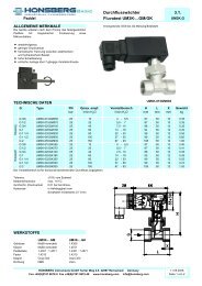
<strong>EF</strong>.. <strong>Flow</strong> <strong>Switches</strong> <strong>10.1.</strong><br />
calorimetric <strong>general</strong> <strong>description</strong> <strong>EF</strong>.<br />
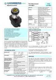
THE TECHNOLOGIE<br />
m/s<br />
The <strong>Honsberg</strong> calorimetric flow switches monitor a variety of substances.<br />
Advantages :<br />
- no moving parts ( versus turbine or variable area)<br />
- unity of wetted material spec<br />
- compact design<br />
- one sensor for all diameters<br />
- low pressure loss<br />
- high operational pressures<br />
- optional integrated temperature control<br />
FIELDS OF USE<br />
- Metal processing industry:<br />
control of coolants and lubricants<br />
- Steel industry:<br />
circuits for cooling agents extraction of heat by current<br />
- Chemical industry:<br />
protecting pumps against running dry,<br />
monitoring for leaks, supervising levels<br />
- Beverage industry:<br />
monitoring cleaning operations<br />
- Air conditioning and ventilation industry:<br />
controlling fans and aeration / ventilation<br />
systems<br />
PRINCIPLE<br />
<strong>Flow</strong> dependent temperature differential is<br />
electronically compensated and serving as<br />
decisive parameter for the flow control.<br />
The variety of sensor options fits almost all operational conditions. If not we are in<br />
the position to adjust our instrument to the individual application.<br />
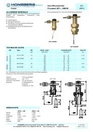
The calorimetric system is based two temperature sensors witch are positioned<br />
within good temperature conductivity versus the liquid involved.<br />
One sensor is permanently heated with the effect that a constant temperature<br />
difference between the sensors will be established. In case of a velocity of the<br />
liquid this temperature difference is modified. This modification is the measure for<br />
the flow control.<br />
The unheated sensor registers the liquid temperature and triggers a temperature<br />
compensation. This effects a stability of temperature behaviour with flow velocity<br />
and an accurate flow control.<br />
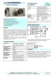
medium<br />
RT1 RT2 heater<br />
basic arrangement of the sensor elements<br />
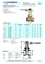
The slope of the curve for a calorimetric sensor<br />
becomes less as the flow rate increases, which<br />
means that the difference signal to be evaluated<br />
becomes increasingly smaller.<br />
HONSBERG Instruments GmbH Tenter Weg 2-8 42897 Remscheid Germany 24.02.2005<br />
Phone +49(0)2191 9672-0 Fax +49(0)2191 9672-40 www.honsberg.com info@honsberg.com page 1 of 4<br />
pipe<br />
Temperature difference<br />
max<br />
0<br />
0 operating<br />
max.<br />
range<br />
f low rate
<strong>EF</strong>.. <strong>Flow</strong> <strong>Switches</strong> <strong>10.1.</strong><br />
calorimetric <strong>general</strong> <strong>description</strong> <strong>EF</strong>.<br />
INFLUENCE OF MEDIUM AND MATERIALS<br />
Various liquids and different sensor housing materials affect the response time,<br />
because the thermal conductivity is changing. Generally, the lower the thermal<br />
conductivity of the medium and the housing material, the higher the medium flow<br />
rate must be to receive satisfactory results.<br />
- medium water - sensor stainless steel - heat conductivity<br />
high => low flow rate required approx. 1..150cm/s<br />
- Medium oil r - sensor stainless steel - heat conductivity<br />
medium => medium flow rate required approx. 3..300cm/s<br />
The operation of the thermal metering and control principle is depending on the<br />
liquid quality and temperature of the metering substance.<br />
Thermal standard instrumentation is calibrated for water in temperature ranges of<br />
15..70°C.<br />
With diverging liquid quality f.i. discourses, air temperature environment of more<br />
than 70°C or less than 15°C an individual advice of the manufactures is<br />
recommended.<br />
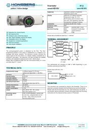
DIFFERENT DESIGNS AND OPTIONS<br />
Calorimetric sensors are manufactured by <strong>Honsberg</strong> in probe configuration. The<br />
probe type is suitable for use with a wide range of pipe cross-sections. Both<br />
designs are manufactured either as compact sensors with integral electronic units<br />
or as sensors for use with external electronic units.<br />
This temperature switch can be used as a safety switch for prohibitive temperature<br />
ranges (please take into account an accuracy of 10%, reproducibility of 1% and<br />
hysteresis of 10%).<br />
EXPLAINATION OF TERMS RELATED<br />
Temperature gradient = change of medium temperature per time unit (K/min).<br />
When rapid temperature changes occur in the medium, they can only be<br />
compensated within a certain range. Correct operation is guaranteed in the<br />
specification range quoted. If the temperature of the medium exceeds this<br />
temperature, the system may generate a fault indication for a short time. Of course,<br />
such fault signal can be filtered by switching delays, compromising the standard<br />
on-off response time.<br />
The stand-by time is the time for the sensor to reach its specified operating mode.<br />
With a supply voltage, all the indicating LEDs illuminate. After approx. 3 s the<br />
display changes to the range set via the potentiometer. Then the switch-off range<br />
can be defined by turning the potentiometer.<br />
The switch-on and switch-off times are the periods after which the regular<br />
measuring variable is acquired following a rapid increase or decrease in the flow<br />
rate. With a medium temperature of approx. 25 °C an d with a stainless steel sensor<br />
used in water , the average switch-on and switch-off times are approx. 2 s. Please<br />
bear in mind that this time depends on the operating conditions. In cases where the<br />
media or sensor materials are poor thermal conductors, the switching times might<br />
increase.<br />
The temperature range of the medium is the range of medium temperature in which<br />
the calorimetric sensor works without problem.<br />
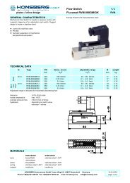
compact types in the form of probes<br />
sensors in the form of probes<br />
external transmitters<br />
sensors in form with elektronic and display<br />
(omni-F)<br />
sensor with switching and frequency exit<br />
4..20mA / 0..10V (Flex-F)<br />
HONSBERG Instruments GmbH Tenter Weg 2-8 42897 Remscheid Germany 24.02.2005<br />
Phone +49(0)2191 9672-0 Fax +49(0)2191 9672-40 www.honsberg.com info@honsberg.com page 2 of 4
<strong>EF</strong>.. <strong>Flow</strong> <strong>Switches</strong> <strong>10.1.</strong><br />
calorimetric <strong>general</strong> <strong>description</strong> <strong>EF</strong>.<br />
The ambient temperature is the temperature surrounding the sensor. This mainly<br />
involves devices and equipment generating or dissipating heat in the vicinity of the<br />
sensor.<br />
The housing material is the material exposed to the medium.<br />
Critical issues for instrument selection:<br />
- the chemical compatibility of wetted materials<br />
- abrasive properties of the material<br />
- reaction time of the sensor<br />
- pressure and temperature characteristics<br />
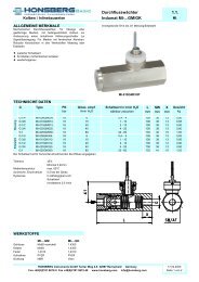
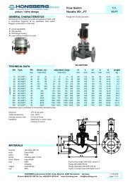
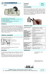
MOUNTING INSTRUCTIONS<br />
In principal all installation locations are feasible where the sensor housing may be<br />
positioned into circumferent contact with the liquid (see drawing):<br />
Contamination and air bubbles shored be avoided. In case of bending tube sectors<br />
the liquid conditions may change which might cause flow whirls and other instability<br />
effecting the quality of emitted signals<br />
After insertion and sealing (e.g. using a Sikurit seal) all sensors can be rotated with<br />
continuous adjustment of the head. This feature facilitates the precise orientation of<br />
the cable and, for the compact-type of sensor, the easy alignment of the indicating<br />
head.<br />
socket and nominal size (standard):<br />
DN H<br />
G probe- Type nominal socket<br />
length diameter dimension<br />
DN H<br />
G1/4A 28 ...-008HK028 DN 10-15 20<br />
DN 20-25 15<br />
G1/2A 29,6 ...-015HK029 DN 15-32 18<br />
G1/2A 45 ...-015HK045 DN 25-.... 32<br />
air bubble<br />
sediments<br />
thread projection of the sensor<br />
HONSBERG Instruments GmbH Tenter Weg 2-8 42897 Remscheid Germany<br />
Phone +49(0)2191 9672-0 Fax +49(0)2191 9672-40 www.honsberg.com info@honsberg.com<br />
high<br />
low<br />
X<br />
flow rate<br />
cable outlet rotable<br />
mark X in f low direction<br />
=max. sensitiv ity and<br />
reaction time<br />
Installation position and consideration<br />
of different flow rates<br />
24.02.2005<br />
page 3 of 4
<strong>EF</strong>.. <strong>Flow</strong> <strong>Switches</strong> <strong>10.1.</strong><br />
calorimetric <strong>general</strong> <strong>description</strong> <strong>EF</strong>.<br />
As accessories for direct installation by female thread fittings (type TS) in brass<br />
and stainless steel are available.<br />
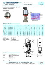
ELECTRICAL INSTALLATION<br />
Probe-type sensors without integral evaluation units are supplied with a cable of<br />
length 2 m (0.25 mm²) as standard. This cable cross-section is used if the external<br />
electronic units are less than 20 m away. If longer distances need to be covered,<br />
the use of an extension cable with full shielding is recommended, along with the<br />
selection of an appropriate diameter corresponding to the cable length.<br />
INSTRUCTIONS FOR HANDLING<br />
AND CALIBRATION<br />
Subsequent to power access the instrument will display full scale operation (all<br />
LED’s lit) for approx. 3 sec.<br />
Once resuming operational temperature the instrument display a flow rate which is<br />
referring to the setting position of the potentiometer.<br />
If you have provided the required flow velocity in your system, select a<br />
potentiometer position which keeps the red LED in operation while all green LED’s<br />
are off duty.<br />
Turning the potentiometer counter clock wise you determine the sensitivity of the<br />
sensor of the calibration setting effects few LED’s only the threshold contact will be<br />
triggered by minor changes in flow velocity, if a chain of green LED’s is activated<br />
minor flow changes are required to create the alarm.<br />
Attention! Please avoid any mechanical strain to the 360° potentiometer.<br />
Potentiometer min<br />
(turn counter clock)<br />
low flow indication,<br />
sensitivity low and<br />
no green LED’s activated.<br />
Potentiometer max<br />
(turn clock wise)<br />
high flow indication,<br />
sensitivity high and<br />
chain of green LED’s activated.<br />
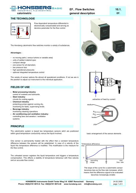
Cross-section of cable conductor ( mm² )<br />
1.50<br />
recommended cable cross-section<br />
for various cable lengths<br />
(1) switch-point indicator for flow (red)<br />
(2) trend indicator for flow (green)<br />
(3) switch-point setting for flow<br />
(4) switch-point setting for the temperature<br />
(only with <strong>EF</strong>KT)<br />
(5) overtemperature indicator (red)<br />
(only with <strong>EF</strong>KT)<br />
1<br />
(1) switch-point indicator for flow (red)<br />
(2) switch-point setting for flow<br />
HONSBERG Instruments GmbH Tenter Weg 2-8 42897 Remscheid Germany<br />
24.02.2005<br />
Phone +49(0)2191 9672-0 Fax +49(0)2191 9672-40 www.honsberg.com info@honsberg.com page 4 of 4<br />
0.75<br />
0.50<br />
0.25<br />
20 50 100 150<br />
3<br />
cable lenght ( m )<br />
1<br />
2<br />
4<br />
5<br />
2