TFT-Display Datenblatt - Hy-Line
TFT-Display Datenblatt - Hy-Line
TFT-Display Datenblatt - Hy-Line

Create successful ePaper yourself
Turn your PDF publications into a flip-book with our unique Google optimized e-Paper software.
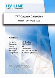
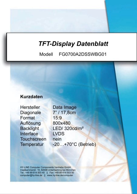
Kurzdaten<br />
<strong>TFT</strong>-<strong>Display</strong> <strong>Datenblatt</strong><br />
Modell FG0700A2DSSWBG01<br />
Hersteller Data Image<br />
Diagonale 7” / 17,8cm<br />
Format 15:9<br />
Auflösung 800x480<br />
Backlight LED/ 320cd/m²<br />
Interface LVDS<br />
Touchscreen nein<br />
Temperatur -20…+70°C (Betrieb)<br />
HY-LINE Computer Components Vertriebs GmbH<br />
Inselkammerstr. 10, 82008 Unterhaching bei München<br />
Tel.: +49 89 614 503 40 || Fax: +49 89 614 503 50<br />
computer@hy-line.de || www.hy-line.de/computer
Confidential Document<br />
DATA IMAGE CORPORATION<br />
<strong>TFT</strong> Module Specification<br />
ITEM NO.: FG0700A2DSSWBG01<br />
Table of Contents<br />
1. COVER & CONTENTS ����������������������������������������������� 1<br />
2. RECORD OF REVISION ��������������������������������������������� 2<br />
3. APPLICATION����������������������������������������������������������� 3<br />
4. GENERAL SPECIFICATIONS ��������������������������������������� 3<br />
5. ABSOLUTE MAXIMUM RATINGS ������������������������������� 3<br />
6. ELECTRICAL CHARACTERISTICS ������������������������������ 3<br />
7. TIMING SPECIFICATIONS ������������������������������������������� 4<br />
8. OPTICAL CHARACTERISTIC �������������������������������������� 7<br />
9. PIN CONNECTIONS ���������������������������������������������������� 10<br />
10. BLOCK DIAGRAM ����������������������������������������������������� 12<br />
11. QUALITY ASSURANCE ���������������������������������������������� 13<br />
12. LCM PRODUCT LABEL DEFINE����������������������������������� 14<br />
13 PRECAUTIONS IN USE LCM ��������������������������������������� 16<br />
14 OUTLINE DRAWING ��������������������������������������������������� 17<br />
15 PACKAGE INFORMATION������������������������������������������� 18<br />
Customer Companies R&D Dept. Q.C. Dept. Eng. Dept. Prod. Dept.<br />
Approved by Version: Issued Date: Sheet Code: Total Pages:<br />
B 5/MAY/11’ 18<br />
FG0700A2DSSWBG01 REV:B Page: 1 /18<br />
HY-LINE Computer Components / www.hy-line.de/computer
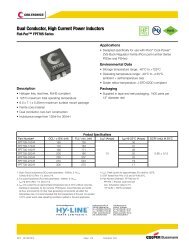
7. TIMING SPECIFICATIONS<br />
DCLK<br />
DE<br />
Confidential Document<br />
ITEM SYMBOL MIN. TYP. MAX. UNIT<br />
Period tCLK 31 37.0 40.0 ns<br />
Dot Clock fCLK 25 27 32.11 MHz<br />
Low Level Width<br />
High Level Width<br />
tWCL<br />
tWCH<br />
8<br />
8<br />
-<br />
-<br />
-<br />
-<br />
ns<br />
Setup Time tDES 5 - -<br />
ns<br />
Hold time tDEH 10 - -<br />
Horizontal Period tHP 850 900 950 tCLK<br />
Horizontal Valid tHV 800<br />
Horizontal Blank tHBK 50 100 150<br />
Vertical Period tVP 490 500 520 tHP<br />
Vertical Valid tVV 480<br />
Vertical Blank tVBK 10 20 40<br />
Vertical Frequency fV 55 60 65 Hz<br />
Setup Time<br />
DATA<br />
Hold Time<br />
tDS<br />
tDH<br />
5<br />
10<br />
-<br />
-<br />
-<br />
-<br />
ns<br />
7.1 TIMING CHARACTERISTIC :<br />
7.1.1Timing Chart<br />
FG0700A2DSSWBG01 REV:B Page: 4 /18<br />
HY-LINE Computer Components / www.hy-line.de/computer
Confidential Document<br />
FG0700A2DSSWBG01 REV:B Page: 5 /18<br />
HY-LINE Computer Components / www.hy-line.de/computer
Confidential Document<br />
7.2 Color Data Input Assignment<br />
Red<br />
Data Signal<br />
Green Blue<br />
Color R5 R4 R3 R2 R1 R0 G5 G4 G3 G2 G1 G0 B5 B4 B3 B2 B1 B0<br />
Basic<br />
Colors<br />
Gray Scale<br />
of Red<br />
Gray Scale<br />
of Green<br />
Gray Scale<br />
of<br />
Blue<br />
Black 0 0 0 0 0 0 0 0 0 0 0 0 0 0 0 0 0 0<br />
Red 1 1 1 1 1 1 0 0 0 0 0 0 0 0 0 0 0 0<br />
Green 0 0 0 0 0 0 1 1 1 1 1 1 0 0 0 0 0 0<br />
Blue 0 0 0 0 0 0 0 0 0 0 0 0 1 1 1 1 1 1<br />
Cyan 0 0 0 0 0 0 1 1 1 1 1 1 1 1 1 1 1 1<br />
Magenta 1 1 1 1 1 1 0 0 0 0 0 0 1 1 1 1 1 1<br />
Yellow 1 1 1 1 1 1 1 1 1 1 1 1 0 0 0 0 0 0<br />
White 1 1 1 1 1 1 1 1 1 1 1 1 1 1 1 1 1 1<br />
Red(0) / Dark 0 0 0 0 0 0 0 0 0 0 0 0 0 0 0 0 0 0<br />
Red(1) 0 0 0 0 0 1 0 0 0 0 0 0 0 0 0 0 0 0<br />
Red(2) 0 0 0 0 1 0 0 0 0 0 0 0 0 0 0 0 0 0<br />
: : : : : : : : : : : : : : : : : : :<br />
: : : : : : : : : : : : : : : : : : :<br />
Red(61) 1 1 1 1 0 1 0 0 0 0 0 0 0 0 0 0 0 0<br />
Red(62) 1 1 1 1 1 0 0 0 0 0 0 0 0 0 0 0 0 0<br />
Red(63) 1 1 1 1 1 1 0 0 0 0 0 0 0 0 0 0 0 0<br />
Green(0)/ Dark 0 0 0 0 0 0 0 0 0 0 0 0 0 0 0 0 0 0<br />
Green(1) 0 0 0 0 0 0 0 0 0 0 0 1 0 0 0 0 0 0<br />
Green(2) 0 0 0 0 0 0 0 0 0 0 1 0 0 0 0 0 0 0<br />
: : : : : : : : : : : : : : : : : : :<br />
: : : : : : : : : : : : : : : : : : :<br />
Green(61) 0 0 0 0 0 0 1 1 1 1 0 1 0 0 0 0 0 0<br />
Green(62) 0 0 0 0 0 0 1 1 1 1 1 0 0 0 0 0 0 0<br />
Green(63) 0 0 0 0 0 0 1 1 1 1 1 1 0 0 0 0 0 0<br />
Blue(0)/ Dark 0 0 0 0 0 0 0 0 0 0 0 0 0 0 0 0 0 0<br />
Blue (1) 0 0 0 0 0 0 0 0 0 0 0 0 0 0 0 0 0 1<br />
Blue (2) 0 0 0 0 0 0 0 0 0 0 0 0 0 0 0 0 1 0<br />
: : : : : : : : : : : : : : : : : : :<br />
: : : : : : : : : : : : : : : : : : :<br />
Blue (61) 0 0 0 0 0 0 0 0 0 0 0 0 1 1 1 1 0 1<br />
Blue (62) 0 0 0 0 0 0 0 0 0 0 0 0 1 1 1 1 1 0<br />
Blue (63) 0 0 0 0 0 0 0 0 0 0 0 0 1 1 1 1 1 1<br />
Correspondence between Data and <strong>Display</strong> Position<br />
S0001 S0002 S0003 S0004 S0005 S0006 S0007 S0008 S2399 S2400<br />
C001 R001 G001 B001 R002 G002 B002 R003 G003 G800 B800<br />
C480 R001 G001 B001 R002 G002 B002 R003 G003 G800 B800<br />
FG0700A2DSSWBG01 REV:B Page: 6 /18<br />
HY-LINE Computer Components / www.hy-line.de/computer
Confidential Document<br />
Note6: Definition of Response Time:<br />
The Response Time is set initially by defining the “Rising Time (Tr)” and the “Falling Time (Tf)” respectively. Tr and Tf are<br />
defined as following figure.<br />
Note 7: Definition of Chromaticity:<br />
The color coordinates (xW,yW),(xR,yR),(xG,yG),and (xB,yB) are obtained with all pixels in the viewing field at white, red, green,<br />
and blue states, respectively.<br />
Note 8: Definition of Image sticking (tis):<br />
Continuously display the test pattern shown in the figure below for 2 hours. Then display a completely white screen. The<br />
previous image shall not persist more than 2 sec at 25 °C<br />
Image sticking pattern<br />
White area<br />
Black area<br />
FG0700A2DSSWBG01 REV:B Page: 9 /18<br />
HY-LINE Computer Components / www.hy-line.de/computer
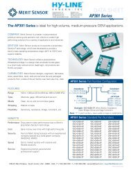
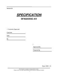
10. BLOCK DIAGRAM<br />
RxIN0(+/-)<br />
RxIN1(+/-)<br />
RxIN2(+/-)<br />
CKIN(+/-)<br />
VDD<br />
VCC<br />
GND<br />
ADJ<br />
INPUT Connector<br />
Scan Driver IC<br />
<strong>TFT</strong><br />
<strong>Display</strong><br />
<strong>TFT</strong>-LCD PANEL<br />
(800xR,G,Bx480)<br />
Data Driver IC<br />
DC/DC Converter<br />
& Reference<br />
Voltage Generator<br />
LVDS INPUT/<br />
Timing Control<br />
LED<br />
Converter(Driver)<br />
Confidential Document<br />
Back light<br />
Unit<br />
FG0700A2DSSWBG01 REV:B Page: 12 /18<br />
HY-LINE Computer Components / www.hy-line.de/computer
12. LCM PRODUCT LABEL DEFINE<br />
Product Label style:<br />
Bar Code<br />
Product<br />
Name<br />
BarCode Define:<br />
A A 6 0014 2 10 26-0013<br />
Year of work order<br />
35mm<br />
AA6001421026-0013<br />
Storage area<br />
FG0700A2DSSWBG01<br />
Serial number of work order<br />
Serial number starts from 0000 each month<br />
Month of work order<br />
The first 3 numbers of work order<br />
Confidential Document<br />
Serial number of the products<br />
Serial number starts from 0000<br />
Every work order is 10K at most<br />
Week of production<br />
Year of production<br />
FG0700A2DSSWBG01 REV:B Page: 14 /18<br />
HY-LINE Computer Components / www.hy-line.de/computer<br />
10mm
13. RECAUTION FOR USING LCM<br />
1. LIQUID CRYSTAL DISPLAY (LCD)<br />
LCD is made up of glass, organic sealant, organic fluid, and<br />
polymer based polarizers. The following precautions should be<br />
taken when handing,<br />
(1). Keep the temperature within range of use and storage.<br />
Excessive temperature and humidity could cause polarization<br />
degradation, polarizer peel off or bubble.<br />
(2). Do not contact the exposed polarizers with anything harder<br />
than an HB pencil lead. To clean dust off the display surface,<br />
wipe gently with cotton, chamois or other soft material soaked in<br />
petroleum benzin.<br />
(3). Wipe off saliva or water drops immediately. Contact with<br />
water over a long period of time may cause polarizer<br />
deformation or color fading, while an active LCD with water<br />
condensation on its surface will cause corrosion of ITO<br />
electrodes.<br />
(4). Glass can be easily chipped or cracked from rough handling,<br />
especially at corners and edges.<br />
(5). Do not drive LCD with DC voltage.<br />
2. Liquid Crystal <strong>Display</strong> Modules<br />
2.1 Mechanical Considerations<br />
LCM are assembled and adjusted with a high degree of<br />
precision. Avoid excessive shocks and do not make any<br />
alterations or modifications. The following should be noted.<br />
(1). Do not tamper in any way with the tabs on the metal frame.<br />
(2). Do not modify the PCB by drilling extra holes, changing its<br />
outline, moving its components or modifying its pattern.<br />
(3). Do not touch the elastomer connector, especially insert an<br />
backlight panel (for example, EL).<br />
(4). When mounting a LCM make sure that the PCB is not under<br />
any stress such as bending or twisting . Elastomer contacts are<br />
very delicate and missing pixels could result from slight<br />
dislocation of any of the elements.<br />
(5). Avoid pressing on the metal bezel, otherwise the elastomer<br />
connector could be deformed and lose contact, resulting in<br />
missing pixels.<br />
2.2. Static Electricity<br />
LCM contains CMOS LSI’s and the same precaution for such<br />
devices should apply, namely<br />
(1). The operator should be grounded whenever he/she comes<br />
into contact with the module. Never touch any of the conductive<br />
parts such as the LSI pads, the copper leads on the PCB and the<br />
interface terminals with any parts of the human body.<br />
(2). The modules should be kept in antistatic bags or other<br />
containers resistant to static for storage.<br />
(3). Only properly grounded soldering irons should be used.<br />
(4). If an electric screwdriver is used, it should be well grounded<br />
and shielded from commutator sparks.<br />
Confidential Document<br />
(5) The normal static prevention measures should be<br />
observed for work clothes and working benches; for the<br />
latter conductive (rubber) mat is recommended.<br />
(6). Since dry air is inductive to statics, a relative<br />
humidity of 50-60% is recommended.<br />
2.3 Soldering<br />
(1). Solder only to the I/O terminals.<br />
(2). Use only soldering irons with proper grounding and<br />
no leakage.<br />
(3). Soldering temperature : 280°C ± 10°C<br />
(4). Soldering time: 3 to 4 sec.<br />
(5). Use eutectic solder with resin flux fill.<br />
(6). If flux is used, the LCD surface should be covered<br />
to avoid flux spatters. Flux residue should be removed<br />
after wards.<br />
2.4 Operation<br />
(1). The viewing angle can be adjusted by varying the<br />
LCD driving voltage V0.<br />
(2). Driving voltage should be kept within specified<br />
range; excess voltage shortens display life.<br />
(3). Response time increases with decrease in<br />
temperature.<br />
(4). <strong>Display</strong> may turn black or dark blue at temperatures<br />
above its operational range; this is (however not<br />
pressing on the viewing area) may cause the segments to<br />
appear “fractured”.<br />
(5). Mechanical disturbance during operation (such as<br />
pressing on the viewing area) may cause the segments to<br />
appear “fractured”.<br />
2.5 Storage<br />
If any fluid leaks out of a damaged glass cell, wash off<br />
any human part that comes into contact with soap and<br />
water. Never swallow the fluid. The toxicity is<br />
extremely low but caution should be exercised at all the<br />
time.<br />
2.6 Limited Warranty<br />
Unless otherwise agreed between DATA IMAGE and<br />
customer, DATA IMAGE will replace or repair any of<br />
its LCD and LCM which is found to be defective<br />
electrically and visually when inspected in accordance<br />
with DATA IMAGE acceptance standards, for a period<br />
on one year from date of shipment. Confirmation of<br />
such date shall be based on freight documents. The<br />
warranty liability of DATA IMAGE is limited to repair<br />
and/or replacement on the terms set forth above. DATA<br />
IMAGE will not responsible for any subsequent or<br />
consequential events.<br />
FG0700A2DSSWBG01 REV:B Page: 16 /18<br />
HY-LINE Computer Components / www.hy-line.de/computer
AUTH<br />
Confidential Document<br />
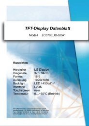
14. OUTLINE DRAWING<br />
A B C D E F<br />
DESCRIPTION DATE<br />
REVISIONS<br />
APPROVED<br />
Peeling Tape<br />
DRAWN:<br />
APPROVE:<br />
07/30/07'<br />
FG0700A2DSSWBG01 REV:B Page: 17 /18<br />
HY-LINE Computer Components / www.hy-line.de/computer<br />
DATE:<br />
CHECK:<br />
Detail "A"<br />
Scale 2:1<br />
TITLE:<br />
7" <strong>TFT</strong> Outline Dimension<br />
DWG. NO.<br />
UNITS<br />
SCALE<br />
M M<br />
1 / 1<br />
FG0700A2-G01<br />
REV.<br />
SHEET 1 OF 1<br />
D<br />
DATA<br />
IMAGE<br />
1<br />
2<br />
3<br />
4<br />
5<br />
6
15.PACKAGE INFORMATION<br />
Carton<br />
Confidential Document<br />
FG0700A2DSSWBG01 REV:B Page: 18 /18<br />
HY-LINE Computer Components / www.hy-line.de/computer