Ei140RC-Series-Instuctions-Rev2

Create successful ePaper yourself
Turn your PDF publications into a flip-book with our unique Google optimized e-Paper software.
WARNING: Mains operated Alarms should be installed<br />
and interconnected by a qualified electrician in accordance<br />
with the Regulations for Electrical Installations published<br />
by the Institution of Electrical Engineers (BS7671).<br />
Failure to install this Alarm correctly may expose the<br />
user to shock or fire hazards.<br />
WARNING: The Alarm must be continuously powered<br />
24 hours a day so it is important that it is not on a circuit<br />
that can be turned off by a switch.<br />
Note: BS 5839-6: 2013 gives the folowing recommendations<br />
regarding the mains supply to be used in a Grade D system (The<br />
Ei141RC, Ei146RC Smoke Alarms and Ei144RC Heat Alarms can<br />
be used in a Grade D system). The power supply for the Alarms<br />
should be derived from the public electricity supply to the dwelling.<br />
The mains supply to the Alarms should take the form of either:<br />
(a) an independent circuit at the dwelling’s main distribution<br />
board, in which case no other electrical equipment should be<br />
connected to this circuit (other than a dedicated monitoring<br />
device installed to indicate failure of the mains supply to the<br />
Alarms); or<br />
(b) a separately electrically protected, regularly used local lighting<br />
circuit.<br />
Alarms should be connected on a single final circuit, unless the<br />
means of interconnection is by radio signals (e.g. RadioLINK).<br />
(See BS 5839-6: 2013 for further information)<br />
Note: The Ei168RC RadioLINK Base can be used to eliminate<br />
interconnect wiring, make system extensions and provide simple<br />
and cost effective compliance with BS 5839-6: 2013.<br />
Mounting & Wiring Alarms<br />
1. Select a location complying with the advice in the<br />
(Positioning Alarms section).<br />
2. Disconnect the AC mains supply from the circuit that<br />
is going to be used.<br />
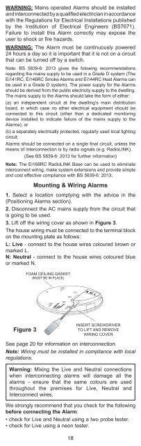
3. Lift off the wiring cover as shown in Figure 3.<br />
The house wiring must be connected to the terminal block<br />
on the mounting plate as follows:<br />
L: Live - connect to the house wires coloured brown or<br />
marked L.<br />
N: Neutral - connect to the house wires coloured blue<br />
or marked N.<br />
FOAM CEILING GASKET<br />
Figure 3<br />
INSERT SCREWDRIVER<br />
TO LIFT AND REMOVE<br />
WIRING COVER<br />
See page 20 for information on interconnection.<br />
Note: Wiring must be installed in compliance with local<br />
regulations.<br />
Warning: Mixing the Live and Neutral connections<br />
when interconnecting alarms will damage all the<br />
alarms - ensure that the same colours are used<br />
throughout the premises for Live, Neutral and<br />
Interconnect wires.<br />
We strongly recommend that you check for the following<br />
before connecting the Alarm:<br />
• check for Live and Neutral using a two probe tester.<br />
• check for Live using a neon tester.<br />
18