Counter-flow regeneration - Purolite
Counter-flow regeneration - Purolite
Counter-flow regeneration - Purolite

Create successful ePaper yourself
Turn your PDF publications into a flip-book with our unique Google optimized e-Paper software.
Engineering Bulletin<br />
PUROLITE ® C100 & C100H<br />
Hydrogen Cycle Operation<br />
Hydrochloric Acid Regeneration<br />
<strong>Purolite</strong> C100 and <strong>Purolite</strong> C100H are industrial grade, premium gel, polystyrenic, strong acid<br />
cation exchange resins supplied in sodium and hydrogen form respectively. Their principal<br />
application is in water demineralization. <strong>Purolite</strong> C100, being supplied in the sodium form, needs<br />
to be converted to the hydrogen form by applying a double or triple acid <strong>regeneration</strong>. As the resin<br />
swells between the sodium and hydrogen form, this must be taken into account in any design<br />
calculations.<br />
This document provides information and engineering data on the removal of cations as part of the<br />
demineralization process. On exhaustion, the resin can be regenerated with different acids. Those<br />
commonly employed are sulfuric acid and hydrochloric acid. This bulletin covers hydrochloric<br />
acid <strong>regeneration</strong> and a separate bulletin is available covering the performance using sulfuric acid.<br />
For more details please consult the Sulfuric Acid Regeneration Engineering Bulletin.<br />
TYPICAL PHYSICAL AND CHEMICAL CHARACTERISTICS<br />
Polymer structure Polystyrene crosslinked with DVB<br />
Physical form Amber, clear spherical beads<br />
Functional groups Sulfonic<br />
Ionic form, as shipped: <strong>Purolite</strong> C100<br />
Na<br />
<strong>Purolite</strong> C100H<br />
+<br />
H +<br />
Total capacity, Na + form 2.0 eq/l (43.7 Kgr/ft 3 ) min.<br />
Moisture retention, Na + form 44 - 48%<br />
Particle size range 300 - 1200 µm<br />
1% max.
Available Grades<br />
<strong>Purolite</strong> C100 and <strong>Purolite</strong> C100H are available in different grades. The list below indicates<br />
products supplied in the Na + form, but H + form versions are also available in most cases.<br />
Single Bed Applications<br />
- <strong>Purolite</strong> C100 is a standard grade resin with a Gaussian particle size distribution in the range<br />
300-1200 μm. Its principal application is in co-<strong>flow</strong> and traditional counter-<strong>flow</strong> regenerated<br />
plants, where classification of the bed inside the operating vessel is possible.<br />
- <strong>Purolite</strong> C100C is a modified grade with a particle size in the range 400-1200 μm, for use in<br />
high <strong>flow</strong> rate applications where the standard grade resin would present an unacceptably high<br />
pressure drop across the bed.<br />
- Purofine ® PFC100 is a Uniform Particle Size product with a mean particle size of 570 µm<br />
and a UC of 1.1-1.2, offering improved performance in softening and demineralization<br />
systems, with regard to capacity, leakage, pressure drop and rinse water requirements.<br />
- Puropack ® PPC100 is another Uniform Particle Size product, offering similar advantages, but<br />
with a mean particle size of 650 µm. This product has been specifically developed for the<br />
PUROPACK ® system and other packed bed counter-<strong>flow</strong> designs employing either up-<strong>flow</strong> or<br />
down-<strong>flow</strong> service operation. This resin has also been widely used in co-<strong>flow</strong> and other<br />
counter-<strong>flow</strong> engineering designs, including air hold down, split <strong>flow</strong>, water hold down, etc..<br />
Both Purofine ® PFC100 and Puropack ® PPC100 have also seen successful operation in<br />
short cycle plants.<br />
- <strong>Purolite</strong> C100S is a specially cleaned and trimmed food grade resin with a particle size in the<br />
range 400-1200 μm, for use in food processing, such as in the sugar industry.<br />
Dual Layer (Stratified Bed) Applications<br />
- <strong>Purolite</strong> C100DL is a specially designed, coarse grade resin, with a particle size range of 630-<br />
1200 μm. Its principal application is in layered bed cation exchange units in conjunction with a<br />
DL grade <strong>Purolite</strong> weak acid cation resin such as <strong>Purolite</strong> C104DLPlus.<br />
Mixed Bed Applications<br />
Three grades of <strong>Purolite</strong> C100 are widely used in mixed beds. These are all specifically designed<br />
to separate well from anion components, whether the anion resins are gel or macroporous. These<br />
cation resins are usually delivered in H + form.<br />
- <strong>Purolite</strong> C100MBH is a modified, simple mixed bed grade resin with a Gaussian particle size<br />
distribution in the range 425-1200 μm. It is used with either gel or macroporous mixed bed<br />
grade anion resins such as <strong>Purolite</strong> A400MB, <strong>Purolite</strong> A600MB, <strong>Purolite</strong> A200MB,<br />
<strong>Purolite</strong> A500MB or <strong>Purolite</strong> A510MB.<br />
- <strong>Purolite</strong> C100TLH is a specially graded resin with a relatively coarse particle size for use in<br />
TRILITE mixed bed systems, with or without intermediate inert, employing internal or<br />
external <strong>regeneration</strong>, in conjunction with a suitable TL grade anion resin, such as <strong>Purolite</strong><br />
A400TL or <strong>Purolite</strong> A500TL.<br />
- Puropack PPC100H is a Uniform Particle Size product, normally used in mixed bed<br />
applications with a slightly finer, uniform particle size Purofine anion resin, such as Purofine ®<br />
PFA400MB or Purofine ® PFA500MB.<br />
USA Europe Asia Pacific<br />
2<br />
Telephone: +1 610 6689090 Telephone: +44 1443 229334 Telephone: +86 571 876 31382<br />
Fax: +1 610 6688139 Fax: +44 1443 227073 Fax: +86 571 876 31385<br />
Email: info@puroliteusa.com Email: sales@purolite.com Email: puroliteasia@purolitechina.com<br />
© 2010 All Rights Reserved www.purolite.com C100 (HCl) Eng Bulletin 0910
Typical Operating Data (Guide to Service Operation and Regeneration)<br />
Service Operation<br />
In service operation water is normally pumped through the resin bed, which is retained within a<br />
pressure vessel. The vessel has top and bottom distribution / collection systems. These systems are<br />
designed to ensure the water passes evenly through the ion exchange bed in service operation. As<br />
the water passes through the resin, the cations (principally calcium, magnesium, sodium,<br />
potassium, iron and any other dissolved cations present) are exchanged with hydrogen ions. The<br />
decationized water has a higher hydrogen (H + ) content, a lower pH and a higher conductivity.<br />
When the resin is exhausted it is then regenerated with an acid solution to put the resin back into<br />
the hydrogen form, ready for the next service operation. It is important for the internal systems<br />
within the cation unit to efficiently distribute and collect both the water in service and the<br />
regenerant acid solution, rinses, etc., especially since the regenerant and rinse <strong>flow</strong> rates are<br />
usually much lower than the service <strong>flow</strong> rate.<br />
In service operation optimum performance is achieved at service <strong>flow</strong> rates between 8 and 40<br />
BV/h (Bed Volumes per hour) or 1 to 5 gpm/ft 3 (US gallons per minute per cubic foot of resin)<br />
within linear <strong>flow</strong> rates (velocities) of 10 to 50 m 3 /m 2 /h (m/h) or 4 to 20 gpm/ft 2 (US gallons per<br />
minute per square foot of vessel cross-section), whereas acid <strong>regeneration</strong> is carried out at <strong>flow</strong><br />
rates of 4 to 16 BV/h or 0.5 to 2.0 gpm/ft 3 . Within these limits internal distribution / collection<br />
systems can operate efficiently at the higher service and lower regenerant <strong>flow</strong> rates. At very low<br />
service <strong>flow</strong> rates channelling can occur within the resin bed resulting in poor plant performance<br />
and short capacity between <strong>regeneration</strong>s. This is particularly likely when long service cycles are<br />
also employed.<br />
The ratio of height to diameter is important in any ion exchange unit design. While some small<br />
industrial demineralization plants operate with very shallow bed depths, bed depths below 610 mm<br />
(2 ft) should be avoided and preferably bed depths greater than 1000 mm (3 ft 3 in) employed.<br />
Vessel height and pressure drop are normally the controlling factor on the maximum height of the<br />
bed. For <strong>Purolite</strong> C100 we recommend that pressure drop across the bed should be maintained at<br />
less than 150 kPa (22 psi), having made allowance for bed compaction and any solids loading<br />
across a classified bed. Bed depths greater than 2500 mm (8 ft) are rarely encountered.<br />
Although smaller freeboards are commonly encountered, we recommend a minimum 75%<br />
freeboard (space) above the resin bed to allow at least 50% bed expansion during backwash. This<br />
is normally adequate for a co-<strong>flow</strong> regenerated vessel, and assures a good hydraulic classification<br />
of the resin bed. Fully classified beds have a higher void fraction which leads to lower pressure<br />
drop. This is particularly advantageous when high specific velocities are encountered.<br />
Service operation is usually terminated by detection of increased conductivity at the exit of the<br />
anion column, due to increased sodium leakage from the cation bed. Occasionally, on large<br />
counter-<strong>flow</strong> regenerated plants, sodium monitors are employed on the outlet of the cation unit to<br />
initiate <strong>regeneration</strong>. The subsequent <strong>regeneration</strong> can be manually or automatically initiated via<br />
the control system.<br />
USA Europe Asia Pacific<br />
3<br />
Telephone: +1 610 6689090 Telephone: +44 1443 229334 Telephone: +86 571 876 31382<br />
Fax: +1 610 6688139 Fax: +44 1443 227073 Fax: +86 571 876 31385<br />
Email: info@puroliteusa.com Email: sales@purolite.com Email: puroliteasia@purolitechina.com<br />
© 2010 All Rights Reserved www.purolite.com C100 (HCl) Eng Bulletin 0910
While co-<strong>flow</strong> and traditional counter-<strong>flow</strong> regenerated plant designs allow backwashing of the<br />
resin bed within the service operation unit, they will only tolerate a low level of suspended solids<br />
present in the incoming water supply. The resins are not expected to work as a mechanical filter,<br />
and an adequate pre-treatment should always be included in the plant layout if optimum<br />
performance is to be achieved.<br />
Regeneration<br />
The resin <strong>regeneration</strong> can be performed either co-<strong>flow</strong> or counter-<strong>flow</strong>. The <strong>regeneration</strong> is<br />
termed co-<strong>flow</strong> when the regenerant <strong>flow</strong>s through the resin bed in the same direction, normally<br />
downwards or “top to bottom”, in which the water <strong>flow</strong>s during the service operation. When the<br />
regenerant <strong>flow</strong> is in the opposite direction to service <strong>flow</strong>, then the term used is counter-<strong>flow</strong><br />
<strong>regeneration</strong>. Other terms such as co-current and counter-current are also used to describe these<br />
two principal <strong>regeneration</strong> techniques.<br />
When counter-<strong>flow</strong> <strong>regeneration</strong> is employed, it is important to note that in the up <strong>flow</strong> stages<br />
(except backwash) the bed must remain static. Packed beds, air hold down, split <strong>flow</strong> and water<br />
hold down are just some of the systems employed to achieve this requirement.<br />
In some counter-<strong>flow</strong> regenerated systems the design allows service <strong>flow</strong> to be upward through the<br />
bed and <strong>regeneration</strong> downwards. In such cases it is important that the bed must remain static<br />
throughout the service operation.<br />
Co-<strong>flow</strong> <strong>regeneration</strong><br />
The co-<strong>flow</strong> <strong>regeneration</strong> technique is normally made up of 5 steps and typically takes between 1<br />
and 2 hours depending on the detailed design. For this type of <strong>regeneration</strong>, the influent water is<br />
typically of adequate quality for all steps, including regenerant dilution.<br />
The first step of co-<strong>flow</strong> <strong>regeneration</strong> is backwash. The backwash water enters the unit through the<br />
bottom collection / distribution system, loosening the bed and causing the bed to expand as the<br />
water passes up through it. The <strong>flow</strong> rate should be set for the freeboard available in the unit at the<br />
minimum water temperature. The backwash is designed to both decompact the resin, for better<br />
regenerant contact, as well as for removing any suspended solids that have been filtered out of the<br />
incoming supply and accumulated within the bed. The backwash water volume required will<br />
depend on the extent of solids loading. Where the bed only requires loosening for better regenerant<br />
contact then 1 FBV (free board volume) is normally sufficient. However, when filtered solids are<br />
present the volume required can be considerably greater. After the backwash a “bed settle” step is<br />
required.<br />
The bed settle allows the resin to settle back and reform the static bed prior to regenerant injection.<br />
Depending on the size of the bed, free board, and backwash rate used, this step can take between 3<br />
and 8 minutes.<br />
USA Europe Asia Pacific<br />
4<br />
Telephone: +1 610 6689090 Telephone: +44 1443 229334 Telephone: +86 571 876 31382<br />
Fax: +1 610 6688139 Fax: +44 1443 227073 Fax: +86 571 876 31385<br />
Email: info@puroliteusa.com Email: sales@purolite.com Email: puroliteasia@purolitechina.com<br />
© 2010 All Rights Reserved www.purolite.com C100 (HCl) Eng Bulletin 0910
Regenerant injection at the correct <strong>flow</strong> rate and acid concentration are critical. Good contact<br />
between the acid solution and the resin is essential for optimum performance. Hydrochloric acid is<br />
easier to use compared to sulfuric acid. This is because there is no risk of calcium sulphate<br />
precipitation as chloride salts are more soluble and hence, higher concentrations of hydrochloric<br />
acid can be employed generating less waste.<br />
The hydrochloric acid <strong>regeneration</strong> level (amount of acid per litre or cubic foot of resin) will<br />
typically be between 60 and 100 g/l (3.75 – 6.25 lbs/ft 3 ), although <strong>regeneration</strong> levels as low as 40<br />
g/l (2.5 lbs/ft 3 ) and as high as 200 g/l (12.5 lbs/ft 3 ) are sometimes employed. Please note all<br />
<strong>regeneration</strong> levels are expressed for the pure chemical (100%) strength. In order to calculate the<br />
exact volume of regenerant required per <strong>regeneration</strong> you need to know the acid concentration<br />
available on site.<br />
Hydrochloric acid should be introduced at <strong>flow</strong> rates of 2 to 4 BV/h (0.25 to 0.5 gpm/ft 3 ) and<br />
concentrations from 4 to 6%. The contact time between the resin and the regenerant solution<br />
should be minimum 20 minutes.<br />
Table 1. Typical Hydrochloric Acid Regeneration Conditions<br />
for Co-<strong>flow</strong> Regenerated Columns<br />
Step Design Basis Duration<br />
Backwash Set for minimum water temperature to<br />
give 50% bed expansion. Refer to<br />
Figure 17 for details.<br />
Bed settle To allow the bed to reform fully<br />
classified<br />
HCl injection 60-100 g/l (3.75-6.25 lb/ft 3 ) applied as<br />
a 4-6% acid solution at 2-4 BV/h (0.25<br />
to 0.5 gpm/ft 3 ). Acid volume needs to<br />
in excess of resin volume.<br />
Slow rinse 1-3 BV (7.5 to 22.5 gal/ft 3 ) at approx.<br />
regenerant <strong>flow</strong> rate<br />
Final rinse 3-6 BV (22.5 to 45 gal/ft 3 ) preferably<br />
at service <strong>flow</strong> rate or alternatively ><br />
15 BV/h (2 US gpm/ft 3 )<br />
1 FBV on clean water supplies and<br />
2-3 FBV where solids are present<br />
3 to 8 minutes<br />
Typically 20-40 minutes depending<br />
on <strong>regeneration</strong> level and <strong>flow</strong> rate<br />
Typically 20-30 minutes depending<br />
on volume of water applied and<br />
<strong>flow</strong> rate<br />
Typically 10-20 minutes<br />
(Key: BV = Bed Volume, BV/h = Bed Volume per hour, FBV = Free board volume above resin bed)<br />
USA Europe Asia Pacific<br />
5<br />
Telephone: +1 610 6689090 Telephone: +44 1443 229334 Telephone: +86 571 876 31382<br />
Fax: +1 610 6688139 Fax: +44 1443 227073 Fax: +86 571 876 31385<br />
Email: info@puroliteusa.com Email: sales@purolite.com Email: puroliteasia@purolitechina.com<br />
© 2010 All Rights Reserved www.purolite.com C100 (HCl) Eng Bulletin 0910
The slow (regenerant displacement) rinse is always carried out at <strong>flow</strong> rates similar to the acid<br />
injection step. This is to ensure a uniform contact time between the resin and the regenerant<br />
solution and that the rinse water follows the same route of the regenerant through the resin bed.<br />
Since slow rinses are usually more efficient in removing the spent regenerant from the resin, using<br />
a longer slow rinse can reduce the amount of final rinse required at the end of the <strong>regeneration</strong>.<br />
Normally 1 to 3 BV (7.5 to 22.5 gal/ft 3 ) of slow rinse are applied.<br />
The final rinse is often carried out at the service <strong>flow</strong> rate. This also acts as a proving condition<br />
prior to returning to service after <strong>regeneration</strong>. On some occasions, where <strong>flow</strong> restrictions occur,<br />
the plant final rinse is carried out at a rate lower than the service <strong>flow</strong> rate. Normally 3 to 6 BV<br />
(22.5 to 45 gal/ft 3 ) are required depending on the design of the distribution / collection systems<br />
and the amount of slow rinsing previously performed.<br />
<strong>Counter</strong>-<strong>flow</strong> <strong>regeneration</strong><br />
Traditional counter-<strong>flow</strong> <strong>regeneration</strong> techniques normally have less steps than those described<br />
earlier for co-<strong>flow</strong> <strong>regeneration</strong> and typically take between 1 and 1½ hours depending on the<br />
detailed design. This type of <strong>regeneration</strong> requires, for some steps, the use of cation free water.<br />
Decationized or demineralized water must be used for the acid dilution / injection and slow rinse<br />
steps, if the published leakage is to be obtained. The water is either set aside during the previous<br />
service run or, in case of multi stream plants, it can be supplied by one of the other on-line<br />
streams. When decationized water is stored for <strong>regeneration</strong>, some plants use a dedicated tank, but<br />
when a degassing tower is part of the process, the degassing tower sump is normally used for this<br />
duty. When demineralized water is used, then the client’s treated water tank or a separate tank are<br />
employed.<br />
In a counter-<strong>flow</strong> regenerated system, the backwash step, which is always the first step of a co<strong>flow</strong><br />
<strong>regeneration</strong>, is not normally performed each cycle, but a means of carrying out periodic full<br />
bed backwashes, either inside the service unit or in external dedicated vessels, should always be<br />
included in the plant design. Some engineering designs allow for sub-surface backwashes to be<br />
carried out each cycle, but such partial backwashes should not be intended as a replacement of<br />
periodic full bed backwashes. After a full bed backwash the resin should always be regenerated<br />
with double the normal amount of acid to restore full counter-<strong>flow</strong> performance.<br />
In counter-<strong>flow</strong> <strong>regeneration</strong> bed depths below 1000 mm (3 ft 3 in) should be avoided and<br />
preferably beds in excess of 1200 mm (4 ft) employed.<br />
The <strong>regeneration</strong> level (amount of acid applied per litre or cubic foot of resin) will be lower than<br />
for co-<strong>flow</strong> regenerated units, typically between 40 and 80 g/l (2.5 – 5 lbs/ft 3 ). However,<br />
<strong>regeneration</strong> levels outside of this range are sometimes employed.<br />
Hydrochloric acid should be introduced at <strong>flow</strong> rates of 2 to 4 BV/h (0.25 to 0.5 gpm/ft 3 ) and<br />
concentrations from 4 to 6%. The contact time between the resin and the regenerant solution<br />
should be minimum 20 minutes.<br />
USA Europe Asia Pacific<br />
6<br />
Telephone: +1 610 6689090 Telephone: +44 1443 229334 Telephone: +86 571 876 31382<br />
Fax: +1 610 6688139 Fax: +44 1443 227073 Fax: +86 571 876 31385<br />
Email: info@puroliteusa.com Email: sales@purolite.com Email: puroliteasia@purolitechina.com<br />
© 2010 All Rights Reserved www.purolite.com C100 (HCl) Eng Bulletin 0910
The slow (regenerant displacement) rinse is always carried out at <strong>flow</strong> rates similar to the acid<br />
injection step and in the same direction. This is to ensure a uniform contact time between the resin<br />
and the regenerant solution and that the rinse water follows the same route of the regenerant<br />
through the resin bed. Since slow rinse is usually more efficient in removing the spent regenerant<br />
from the resin than fast rinse, using more slow rinse can reduce the amount of final rinse required.<br />
Normally 1 to 2 BV (7.5 to 15 US gal/ft 3 ) of slow rinse are adequate.<br />
The final rinse is often carried out at the service <strong>flow</strong> rate. This also acts as a proving condition<br />
prior to returning to service after <strong>regeneration</strong>. Normally 2 to 4 BV (15 to 30 US gal/ft 3 ) are<br />
required depending on the design of the distribution / collection system and the amount of slow<br />
rinsing previously performed.<br />
It is more and more common in demineralization plants to employ closed-loop recycle rinses<br />
around the cation and anion units. This offers two advantages: it reduces the amount of waste<br />
water produced by the plant and it allows the design to include a proving pre-service rinse prior to<br />
placing the line back in service. Where anion resins sometimes develop long rinses due to organic<br />
fouling, a recycle rinse system can significantly reduce water consumption and avoid resins<br />
overloading.<br />
Table 2. Typical Hydrochloric Acid Regeneration Conditions<br />
for <strong>Counter</strong>-<strong>flow</strong> Regenerated Columns<br />
Step Design Basis Duration<br />
HCl injection 40-80 g/l (2.5-5.0 lb/ft 3 ) applied as a<br />
4-6% acid solution at 2-4 BV/h (0.25<br />
to 0.5 US gpm/ft 3 ). Acid volume<br />
needs to in excess of resin volume.<br />
Slow rinse 1-2 BV (7.5 to 15 gal/ft 3 ) at approx.<br />
regenerant <strong>flow</strong> rate<br />
Final rinse 2-4 BV (15 to 30 gal/ft 3 ) preferably at<br />
service <strong>flow</strong> rate or alternatively > 15<br />
BV/h (2 gpm/ft 3 )<br />
Typically 20-40 minutes depending<br />
on <strong>regeneration</strong> level and <strong>flow</strong> rate<br />
Typically 20-30 minutes depending<br />
on volume of water applied and<br />
<strong>flow</strong> rate<br />
Typically 10-20 minutes<br />
(Key: BV = Bed Volume, BV/h = Bed Volume per hour)<br />
<strong>Purolite</strong> C100 and <strong>Purolite</strong> C100H are perfectly suitable for traditional counter-<strong>flow</strong><br />
<strong>regeneration</strong> systems but, when more sophisticated plant designs are used, other more specialized<br />
grades, such as Purofine PFC100 or Puropack PPC100, can enhance the performance further.<br />
Consult your local <strong>Purolite</strong> sales office if you need any guidance.<br />
USA Europe Asia Pacific<br />
7<br />
Telephone: +1 610 6689090 Telephone: +44 1443 229334 Telephone: +86 571 876 31382<br />
Fax: +1 610 6688139 Fax: +44 1443 227073 Fax: +86 571 876 31385<br />
Email: info@puroliteusa.com Email: sales@purolite.com Email: puroliteasia@purolitechina.com<br />
© 2010 All Rights Reserved www.purolite.com C100 (HCl) Eng Bulletin 0910
Performance Data<br />
The following graphs and correction factors are designed to help the design engineer to estimate<br />
the exchange capacity and hardness leakage achieved with <strong>Purolite</strong> C100 and <strong>Purolite</strong> C100H<br />
under different operating conditions. All the data shown are the result of years of industrial<br />
experience and are supplied in good faith. The final performance will depend on the detailed<br />
design and operation of the system, the quality of the regenerant chemicals as well as the long<br />
term maintenance of the plant. Some engineers who are using basic, standard plant of simple<br />
design may wish to take a design margin (safety factor) with regard to the published data to allow<br />
for less than ideal operation. Please note the data presented in this section are specific to co-<strong>flow</strong><br />
regenerated designs with bed depths over 1000 mm (3 ft 3 in) and counter-<strong>flow</strong> regenerated<br />
designs with bed depths over 1200 mm (6 ft 6 in). For shallower bed depths there may be a<br />
requirement to down rate the expected performance depending on the quality of the design.<br />
The data supplied are divided in three groups: figures 1 to 8 deal with capacity and leakage for co<strong>flow</strong><br />
<strong>regeneration</strong>, figures 9 to 16 with capacity and leakage for counter-<strong>flow</strong> <strong>regeneration</strong> and<br />
figures 17 to 18 with hydraulic data (backwash expansion and pressure drop). Within each of the<br />
first two groups there is a base capacity and a base leakage curve, both followed by other curves<br />
showing correction factors. To calculate the expected capacity or leakage, multiply the base<br />
capacity or leakage by the relevant correction factors.<br />
For users interested in performing these engineering calculations electronically, <strong>Purolite</strong>’s<br />
PureDesign software is available for download via www.purolite.com at no charge.<br />
The data presented in this bulletin can also be used to estimate the operating performances of<br />
resins such as <strong>Purolite</strong> C100C, <strong>Purolite</strong> C100S or <strong>Purolite</strong> C100DL, while it is recommended to<br />
refer to dedicated engineering bulletins for products like Purofine ® PFC100 and Puropack ®<br />
PPC100.<br />
USA Europe Asia Pacific<br />
8<br />
Telephone: +1 610 6689090 Telephone: +44 1443 229334 Telephone: +86 571 876 31382<br />
Fax: +1 610 6688139 Fax: +44 1443 227073 Fax: +86 571 876 31385<br />
Email: info@puroliteusa.com Email: sales@purolite.com Email: puroliteasia@purolitechina.com<br />
© 2010 All Rights Reserved www.purolite.com C100 (HCl) Eng Bulletin 0910
Base capacity, eq/l<br />
1.8<br />
1.6<br />
1.4<br />
1.2<br />
1.0<br />
0.8<br />
0.6<br />
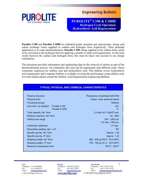
Figure 1<br />
Base capacity (co-<strong>flow</strong> <strong>regeneration</strong>)<br />
Regeneration level, lb 100% HCl/ft 3<br />
0 4 8 12<br />
Co-<strong>flow</strong> <strong>regeneration</strong><br />
0 40 80 120 160 200<br />
Regeneration level, g 100% HCl/l<br />
Figure 1 provides base capacity data for <strong>Purolite</strong> C100, delivered in sodium form.<br />
Capacity of <strong>Purolite</strong> C100H, delivered in hydrogen form, is expected to be 8% lower<br />
than shown in this graph.<br />
USA Europe Asia Pacific<br />
9<br />
Telephone: +1 610 6689090 Telephone: +44 1443 229334 Telephone: +86 571 876 31382<br />
Fax: +1 610 6688139 Fax: +44 1443 227073 Fax: +86 571 876 31385<br />
Email: info@puroliteusa.com Email: sales@purolite.com Email: puroliteasia@purolitechina.com<br />
© 2010 All Rights Reserved www.purolite.com C100 H cycle H2SO4 Eng Bull_20Jul2010<br />
2010<br />
38<br />
33<br />
28<br />
23<br />
18<br />
13<br />
Base capacity, Kgr/ft 3
C1<br />
C2<br />
1.10<br />
1.05<br />
1.00<br />
0.95<br />
0.90<br />
1.2<br />
1.1<br />
1.0<br />
0.9<br />
0.8<br />
Figure 2<br />
C1 - Capacity correction factor<br />
Total Alkalinity / Total Anions<br />
Co-<strong>flow</strong> <strong>regeneration</strong><br />
0 20 40 60 80 100<br />
Total Alkalinity / Total Anions ratio, %<br />
Figure 3<br />
C2 - Capacity correction factor for temperature<br />
Water temperature, °F<br />
32 40 48 56 64 72 80 88<br />
0 5 10 15 20 25 30 35<br />
Water temperature, °C<br />
USA Europe Asia Pacific<br />
10<br />
Telephone: +1 610 6689090 Telephone: +44 1443 229334 Telephone: +86 571 876 31382<br />
Fax: +1 610 6688139 Fax: +44 1443 227073 Fax: +86 571 876 31385<br />
Email: info@puroliteusa.com Email: sales@purolite.com Email: puroliteasia@purolitechina.com<br />
© 2010 All Rights Reserved www.purolite.com C100 H cycle H2SO4 Eng Bull_20Jul2010<br />
2010
C3<br />
C4<br />
1.3<br />
1.2<br />
1.1<br />
1.0<br />
0.9<br />
1.05<br />
1.00<br />
0.95<br />
0.90<br />
0.85<br />
Figure 4<br />
C3 - Capacity correction factor<br />
for Na / Total Cations<br />
Co-<strong>flow</strong> <strong>regeneration</strong><br />
0 20 40 60 80 100<br />
Na / Total Cations ratio, %<br />
Figure 5<br />
C4 - Capacity correction factor for<br />
kinetic load (Specific <strong>flow</strong> rate · Total Cations)<br />
Kinetic load, BV/h · Kgr/ft<br />
0 3 6 9 12 15 18<br />
3<br />
TAlk/TA = 0%<br />
TAlk/TA = 50%<br />
TAlk/TA = 100%<br />
0 150 300 450 600 750 900<br />
Kinetic load, BV/h · meq/l<br />
USA Europe Asia Pacific<br />
11<br />
Telephone: +1 610 6689090 Telephone: +44 1443 229334 Telephone: +86 571 876 31382<br />
Fax: +1 610 6688139 Fax: +44 1443 227073 Fax: +86 571 876 31385<br />
Email: info@puroliteusa.com Email: sales@purolite.com Email: puroliteasia@purolitechina.com<br />
© 2010 All Rights Reserved www.purolite.com C100 H cycle H2SO4 Eng Bull_20Jul2010<br />
2010
L1<br />
Base leakage, ppm Na<br />
2.0<br />
1.5<br />
1.0<br />
0.5<br />
0.0<br />
12<br />
9<br />
6<br />
3<br />
0<br />
Figure 6<br />
Base Sodium Leakage<br />
Co-<strong>flow</strong> <strong>regeneration</strong><br />
Regeneration level, lb 100% HCl/ft<br />
0 2 4 6 8 10 12<br />
3<br />
0 50 100 150 200<br />
Regeneration level, g 100% HCl/l<br />
Figure 7<br />
L1 - Capacity correction factor<br />
for Equivalent Mineral Acidity<br />
0 0.1<br />
EMA, Kgr/ft<br />
0.2 0.3 0.4<br />
3<br />
0 4 8 12 16 20<br />
EMA, meq/l<br />
USA Europe Asia Pacific<br />
12<br />
Telephone: +1 610 6689090 Telephone: +44 1443 229334 Telephone: +86 571 876 31382<br />
Fax: +1 610 6688139 Fax: +44 1443 227073 Fax: +86 571 876 31385<br />
Email: info@puroliteusa.com Email: sales@purolite.com Email: puroliteasia@purolitechina.com<br />
© 2010 All Rights Reserved www.purolite.com C100 H cycle H2SO4 Eng Bull_20Jul2010<br />
2010
L2<br />
4<br />
3<br />
2<br />
1<br />
0<br />
Figure 8<br />
L2 - Leakage correction factor for<br />
Na / Total Cations<br />
Co-<strong>flow</strong> <strong>regeneration</strong><br />
0 20 40 60 80 100<br />
Na / Total Cations ratio, %<br />
USA Europe Asia Pacific<br />
13<br />
Telephone: +1 610 6689090 Telephone: +44 1443 229334 Telephone: +86 571 876 31382<br />
Fax: +1 610 6688139 Fax: +44 1443 227073 Fax: +86 571 876 31385<br />
Email: info@puroliteusa.com Email: sales@purolite.com Email: puroliteasia@purolitechina.com<br />
© 2010 All Rights Reserved www.purolite.com C100 H cycle H2SO4 Eng Bull_20Jul2010<br />
2010
Base capacity, eq/l<br />
1.8<br />
1.6<br />
1.4<br />
1.2<br />
1.0<br />
0.8<br />
<strong>Counter</strong>-<strong>flow</strong> <strong>regeneration</strong><br />
Figure 9<br />
Base capacity (counter-<strong>flow</strong> <strong>regeneration</strong>)<br />
Regeneration level, lb 100% HCl/ft 3<br />
0 3 6 9<br />
0 40 80 120 160<br />
Regeneration level, g 100% HCl/l<br />
Figure 9 provides base capacity data for <strong>Purolite</strong> C100, delivered in sodium form.<br />
Capacity of <strong>Purolite</strong> C100H, delivered in hydrogen form, is expected to be 8% lower<br />
than shown in this graph.<br />
USA Europe Asia Pacific<br />
14<br />
Telephone: +1 610 6689090 Telephone: +44 1443 229334 Telephone: +86 571 876 31382<br />
Fax: +1 610 6688139 Fax: +44 1443 227073 Fax: +86 571 876 31385<br />
Email: info@puroliteusa.com Email: sales@purolite.com Email: puroliteasia@purolitechina.com<br />
© 2010 All Rights Reserved www.purolite.com C100 H cycle H2SO4 Eng Bull_20Jul2010<br />
2010<br />
37<br />
32<br />
27<br />
22<br />
17<br />
Base capacity, Kgr/ft 3
C2<br />
C1<br />
1.10<br />
1.05<br />
1.00<br />
0.95<br />
0.90<br />
1.10<br />
1.05<br />
1.00<br />
0.95<br />
0.90<br />
<strong>Counter</strong>-<strong>flow</strong> <strong>regeneration</strong><br />
Figure 10<br />
C1 - Capacity correction factor Na / Total Cations<br />
0 20 40 60 80 100<br />
Na / Total Cations ratio, %<br />
Figure 11<br />
C2 - Capacity correction factor<br />
Total Alkalinity / Total Anions<br />
0 20 40 60 80 100<br />
Total Alkalinity / Total Anions ratio, %<br />
USA Europe Asia Pacific<br />
15<br />
Telephone: +1 610 6689090 Telephone: +44 1443 229334 Telephone: +86 571 876 31382<br />
Fax: +1 610 6688139 Fax: +44 1443 227073 Fax: +86 571 876 31385<br />
Email: info@puroliteusa.com Email: sales@purolite.com Email: puroliteasia@purolitechina.com<br />
© 2010 All Rights Reserved www.purolite.com C100 H cycle H2SO4 Eng Bull_20Jul2010<br />
2010
C3<br />
C4<br />
1.10<br />
1.05<br />
1.00<br />
0.95<br />
0.90<br />
1.10<br />
1.05<br />
1.00<br />
0.95<br />
0.90<br />
<strong>Counter</strong>-<strong>flow</strong> <strong>regeneration</strong><br />
Figure 12<br />
C3 - Capacity correction factor for temperature<br />
Water Temperature, °F<br />
32 40 48 56 64 72 80 88<br />
0 5 10 15 20 25 30 35<br />
Water temperature, °C<br />
Figure 13<br />
C4 - Capacity correction factor for bed depth<br />
Bed depth, in<br />
20 40 60 80 100<br />
0.5 1.0 1.5 2.0 2.5 3.0<br />
Bed depth, m<br />
USA Europe Asia Pacific<br />
16<br />
Telephone: +1 610 6689090 Telephone: +44 1443 229334 Telephone: +86 571 876 31382<br />
Fax: +1 610 6688139 Fax: +44 1443 227073 Fax: +86 571 876 31385<br />
Email: info@puroliteusa.com Email: sales@purolite.com Email: puroliteasia@purolitechina.com<br />
© 2010 All Rights Reserved www.purolite.com C100 H cycle H2SO4 Eng Bull_20Jul2010<br />
2010
C5<br />
C6<br />
<strong>Counter</strong>-<strong>flow</strong> <strong>regeneration</strong><br />
Figure 14<br />
C5 - Capacity correction factor for specific <strong>flow</strong> rate<br />
1.05<br />
1.00<br />
0.95<br />
0.90<br />
0.85<br />
0.80<br />
1.05<br />
1.00<br />
0.95<br />
0.90<br />
0.85<br />
0.80<br />
Specific <strong>flow</strong> rate, gpm/ft<br />
2 3 4 5 6 7<br />
3<br />
<strong>regeneration</strong> level = 40 g/l (2.5 lb/ft3)<br />
<strong>regeneration</strong> level = 50 g/l (3.1 lb/ft3)<br />
<strong>regeneration</strong> level = 60 g/l (3.7 lb/ft3)<br />
16 24 32 40 48 56<br />
Specific <strong>flow</strong> rate, BV/h<br />
Figure 15<br />
C6 - Capacity correction factor for<br />
kinetic load (Specific <strong>flow</strong> rate · Total Cations)<br />
Kinetic load, BV/h · Kgr/ft<br />
0 2 4 6 8 10 12 14<br />
3<br />
TAlk/TA = 0%<br />
TAlk/TA = 50%<br />
TAlk/TA = 100%<br />
0 100 200 300 400 500 600 700<br />
Kinetic load, BV/h · meq/l<br />
USA Europe Asia Pacific<br />
17<br />
Telephone: +1 610 6689090 Telephone: +44 1443 229334 Telephone: +86 571 876 31382<br />
Fax: +1 610 6688139 Fax: +44 1443 227073 Fax: +86 571 876 31385<br />
Email: info@puroliteusa.com Email: sales@purolite.com Email: puroliteasia@purolitechina.com<br />
© 2010 All Rights Reserved www.purolite.com C100 H cycle H2SO4 Eng Bull_20Jul2010<br />
2010
Base leakage, ppb Na<br />
40<br />
30<br />
20<br />
10<br />
0<br />
Figure 16<br />
Sodium Leakage<br />
<strong>Counter</strong>-<strong>flow</strong> <strong>regeneration</strong><br />
Regeneration level, lb 100% HCl/ft<br />
0 2 4 6 8<br />
3<br />
0 20 40 60 80 100 120 140<br />
Regeneration level, g 100% HCl/l<br />
USA Europe Asia Pacific<br />
18<br />
Telephone: +1 610 6689090 Telephone: +44 1443 229334 Telephone: +86 571 876 31382<br />
Fax: +1 610 6688139 Fax: +44 1443 227073 Fax: +86 571 876 31385<br />
Email: info@puroliteusa.com Email: sales@purolite.com Email: puroliteasia@purolitechina.com<br />
© 2010 All Rights Reserved www.purolite.com C100 H cycle H2SO4 Eng Bull_20Jul2010<br />
2010
Bed expansion, %<br />
120<br />
100<br />
80<br />
60<br />
40<br />
20<br />
Pressure drop, kPa/m<br />
0<br />
Figure 17<br />
Backwash expansion<br />
Hydraulic characteristics<br />
Linear <strong>flow</strong> rate, gpm/ft<br />
0 2 4 6 8 10 12 14<br />
2<br />
5°C / 41°F<br />
10°C / 50°F<br />
20°C / 68°F<br />
30°C / 86°F<br />
0 5 10 15 20 25 30 35<br />
Linear <strong>flow</strong> rate, m/h<br />
100<br />
80<br />
60<br />
40<br />
20<br />
0<br />
Figure 18<br />
Pressure drop<br />
0 5 10 15 20<br />
10°C / 50°F<br />
20°C / 68°F<br />
30°C / 86°F<br />
40°C / 104°F<br />
Linear <strong>flow</strong> rate, gpm/ft 2<br />
0 10 20 30 40 50 60<br />
Linear <strong>flow</strong> rate, m/h<br />
USA Europe Asia Pacific<br />
19<br />
Telephone: +1 610 6689090 Telephone: +44 1443 229334 Telephone: +86 571 876 31382<br />
Fax: +1 610 6688139 Fax: +44 1443 227073 Fax: +86 571 876 31385<br />
Email: info@puroliteusa.com Email: sales@purolite.com Email: puroliteasia@purolitechina.com<br />
© 2010 All Rights Reserved www.purolite.com C100 H cycle H2SO4 Eng Bull_20Jul2010<br />
2010<br />
4.0<br />
3.0<br />
2.0<br />
1.0<br />
0.0<br />
Pressure drop, psi/ft
Additional information & application notes<br />
Safety: Strong oxidants, such as nitric acid, may cause violent reactions with ion exchange resins under certain<br />
conditions. Use of strong oxidants must be done under the care and supervision of persons knowledgeable in<br />
handling these types of materials.<br />
MSDS/SDS: Material Safety Data Sheets/Safety Data Sheets are available on <strong>Purolite</strong>’s website,<br />
www.purolite.com. MSDS sheets should be consulted for additional information on product safety, handling and<br />
disposal.<br />
Storage and Transportation: Information on the proper storage and transportation can be found on <strong>Purolite</strong>’s<br />
website, www.purolite.com.<br />
Notice: The information contained in this document, including application, technical specifications and operation<br />
utilizing <strong>Purolite</strong> products is provided in good faith and without warranty. Use of our products is out of our<br />
control. It is important that you test our products for suitability in your application and environment. Testing<br />
should include health, safety and material handling as well as application. Unless otherwise agreed, all products<br />
are sold according to our General Terms and Conditions of sale. It is expressly understood that you undertake all<br />
responsibility and liability for use of the product. No license is implied or in fact granted under the claims of any<br />
patent. No other warranty of any kind, express or implied, whether of fitness or merchantability is made as to the<br />
material sold or any instructions or technical advice provided, unless separately agreed in writing.<br />
USA Europe Asia Pacific<br />
20<br />
Telephone: +1 610 6689090 Telephone: +44 1443 229334 Telephone: +86 571 876 31382<br />
Fax: +1 610 6688139 Fax: +44 1443 227073 Fax: +86 571 876 31385<br />
Email: info@puroliteusa.com Email: sales@purolite.com Email: puroliteasia@purolitechina.com<br />
© 2010 All Rights Reserved www.purolite.com C100 H cycle H2SO4 Eng Bull_20Jul2010<br />
2010