Stray Current Design Details Mass Transit Light Rail Transit ...
Stray Current Design Details Mass Transit Light Rail Transit ...
Stray Current Design Details Mass Transit Light Rail Transit ...
Create successful ePaper yourself
Turn your PDF publications into a flip-book with our unique Google optimized e-Paper software.
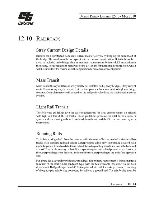
12-10 RAILROADS<br />
<strong>Stray</strong> <strong>Current</strong> <strong>Design</strong> <strong>Details</strong><br />
BRIDGE DESIGN DETAILS 12-10 • MAY 2010<br />
Bridges can be protected from stray current most effectively by keeping the current out of<br />
the bridge. This work must be incorporated in the railroad construction. <strong>Details</strong> shown here<br />
are to be included in the bridge plans as minimum requirements for future LRT installation on<br />
the bridge. The actual design plans will be the LRT plans for the railroad construction, which<br />
will be submitted for review with the application for an encroachment permit.<br />
<strong>Mass</strong> <strong>Transit</strong><br />
<strong>Mass</strong> transit (heavy rail) tracks are typically not installed on highway bridges. <strong>Stray</strong> current<br />
control/monitoring may be required at traction power substations next to highway bridge<br />
footings. Control measures will depend on the bridges involved and the track/traction power<br />
system.<br />
<strong>Light</strong> <strong>Rail</strong> <strong>Transit</strong><br />
The following guidelines give the basic requirements for stray current control on bridges<br />
with light rail transit (LRT) tracks. These guidelines presume the LRT to be a modern<br />
system with the running rails well insulated from the soil and the DC traction power system<br />
ungrounded.<br />
Running <strong>Rail</strong>s<br />
To isolate a bridge deck from the running rails, the most effective method is tie-on-ballast<br />
tracks with standard railroad bridge waterproofing using butyl membrane covered with<br />
asphaltic panels. For a fixed abutment extend the waterproofing membrane down the backwall<br />
at least 20 inches below any ballast. If an expansion joint is involved provide a detail to carry<br />
the waterproofing across the joint, and continue the waterproofing to the end of the approach<br />
slab.<br />
For a bare deck, several provisions are required. The primary requirement is insulating track<br />
fasteners of the steel-rubber sandwich type, with the best available insulating values both<br />
dry and wet. Bridges longer than 100 feet require a drain path for leakage current, consisting<br />
of the grade pad reinforcing connected by cable to a ground bed. The reinforcing must be<br />
RAILROADS<br />
12-10.1
12-10.2 RAILROADS<br />
BRIDGE DESIGN DETAILS 12-10 • MAY 2010<br />
welded to make it electrically continuous and connected by cable across drainage openings<br />
and around expansion joints.<br />
Traction Power<br />
Third rail posts and overhead contact system (OCS) poles and other mounting hardware for<br />
the DC positive are required to be grounded for safety. Connect mounting hardware with an<br />
insulated copper cable to a ground bed separate from the ground bed for the running rails.<br />
To control stray current, mounting hardware needs to be isolated from the bridge. Use<br />
epoxy-coated foundation bolts, epoxy achorages, etc.<br />
Ground Beds<br />
Ground beds must be separated from footings a distance equal to the substructure depth<br />
(spread footing or pile tip depth). The OCS and running rail ground beds must be separated<br />
from each other by the ground bed depth.<br />
Bridges longer than 1000 feet require two grounds beds. The ground bed must be designed<br />
and cable sized such that the resistance to remote soil from any point on the bridge must be<br />
kept below 5 ohms.<br />
All bridges longer than 1000 feet require continuous remote monitoring.<br />
Contract Plans<br />
Insert a sheet in the contract plans showing the stray current requirements for future light<br />
rail installation if light rail load ratings are shown. On the load ratings sheet, refer to the stray<br />
current details sheet to alert the encroachment permit engineer for future installations.<br />
EXAMPLE ALERT: I-105 GUIDELINES FOR LRT STRAY CURRENT PROVISIONS<br />
Discussion<br />
The following guidelines give the basic requirements for stray current control on prestressed<br />
or reinforced concrete box girder bridges of the I-105 Project including the Airport Viaduct.<br />
Providing electrical interconnection will mitigate internal stray current corrosion, particularly<br />
for prestressing elements. These guideline procedures, plus an insulating coating on the
BRIDGE DESIGN DETAILS 12-10 • MAY 2010<br />
deck, should control LRT stray current. <strong>Details</strong> 1 through 3, 4A & 4B, 5, 6, 7A & 7B, 8 thru<br />
13, plus Standard Sheets 20-24 (XS-10-33) and 20-25 (XS-10-34) illustrate the following<br />
guidelines.<br />
I-105 UNDERCROSSINGS, SEPARATIONS, AND VIADUCT<br />
INTERCONNECTION OF REINFORCING AND PRESTRESS TENDONS<br />
Deck<br />
CIP Prestressed Bridge:<br />
Lap weld all continuous top longitudinal rebar splices within the width of LRT trackway.<br />
<strong>Design</strong>er must designate these bars on a plan sheet. See Detail 1. (Note: The typical section<br />
shown on the bridge General Plan should define the limits of LRT trackway. Usually this is<br />
from inside face to inside face of the concrete barriers.)<br />
Reinforced Concrete Bridge:<br />
Provide an extra (non-structural) lap-welded continuous top longitudinal #4 rebar in the deck<br />
slab at each girder and within one foot of the inside face of the future concrete barriers.<br />
Provided only within the width of the LRT trackway. <strong>Design</strong>er must designate these bars on<br />
a plan sheet. See Detail 1.<br />
Both Bridge Types:<br />
Weld connect the above mentioned longitudinal bars to a transverse collector bar (#9 rebar)<br />
at each bent cap, hinge diaphragm, abutment diaphragm and abutment backwall. (See <strong>Details</strong><br />
1 through 9.)<br />
Superstructure Hinge<br />
Exothermic weld two #2/0 copper cables to collector bars in both diaphragms; pass #2/0<br />
cable through a 2" duct. See Detail 3.<br />
RAILROADS<br />
12-10.3
Abutment with Spread Footing<br />
BRIDGE DESIGN DETAILS 12-10 • MAY 2010<br />
Provide transverse collector bar (#9 rebar) in the top of abutment backwalls in seat type<br />
abutments. Weld connect all backwall exterior face vertical rebars to the collector bar within<br />
LRT trackway width. See Detail 4A. Provide transverse collector bar (#9 rebar) at the top<br />
of the abutment diaphragm as described under “Deck” subject. See <strong>Details</strong> 4A & 4B.<br />
Exothermic weld one #2/0 copper cable to each collector bar. See Detail 4A & 4B. Bring<br />
cables through abutment back wall if it exists (no duct), direct bury in ground to #5 pull box<br />
at end of wingwall.<br />
Apply membrane insulation on abutment diaphragm end surface. See <strong>Details</strong> 4A & 4B.<br />
Use epoxy coated approach slab tie rods in full width of bridge. Permit only high density<br />
mortar blocks.<br />
Abutment with Pile Cap Footing<br />
Same provisions as Abutment with Spread Footing plus the following pile provisions: Permit<br />
only Alternative “X” and “Y” driven piles. Special details for 16" C.I.D.H. Piles. See Standard<br />
Sheets 20-24 (XS-10-33) and 20-25 (XS-10-34). <strong>Design</strong>er shall eliminate the requirements<br />
shown on the standard sheets for epoxy coated reinforcing and epoxy coating insulate at pile<br />
tops and pile sides at all abutments.<br />
Prestress Tendons<br />
Weld connect the #9 collector bar to one prestress strand in each prestress anchor plate by<br />
using a #6 collector wire. See Detail 5. Place 4 x 4, W4.0 x W4.0 WWR shield over prestress<br />
plate area at the abutment blockouts. Weld connect at least one fabric wire to the #6 connector<br />
wire. See Detail 5.<br />
Columns<br />
12-10.4 RAILROADS<br />
Weld connect one main column bar to the transverse collector bar in the bent cap using a #6<br />
rebar. See <strong>Details</strong> 6 through 9. Coat column concrete surface below ground and 6" minimum<br />
above ground with membrane insulation. Permit only high density mortar blocks to be used.<br />
Provide a test box in the column face 3'-0" above finish ground surface. Connect to the one<br />
main column bar with a #12 copper wire. See Detail 11.
Columns with Spread Footing<br />
Hinged Column at Footing:<br />
BRIDGE DESIGN DETAILS 12-10 • MAY 2010<br />
Hinge vertical rebar shall be epoxy coated and no contact to column cage rebar permitted.<br />
Provide hinge spiral discontinuity in top of footing. Provide sealant at column hinge joint. See<br />
Detail 6.<br />
Fixed Column at Footing:<br />
The one main column bar connected to the deck transverse collector bar shall be electrically<br />
continuous (by welding) through the footing. Coat all top of footing surfaces with membrane<br />
insulation. Provide 6" deep concrete course beneath footing. Provide depressed keys at top.<br />
Permit only high density mortar blocks. See Detail 7B.<br />
Column with Pile Footing<br />
Hinged Column at Footing:<br />
Same details as spread footing. See Detail 6. In addition only Alternative “X” and “Y” driven<br />
piles permitted. Special details for 16" C.I.D.H. Piles. See Standard sheets 20-24 (XS-10-<br />
33) and 20-25 (XS-10-34) except designer shall eliminate epoxy coated reinforcing and<br />
epoxy insulation at pile top and sides.<br />
Fixed Column at Footing:<br />
Same as fixed column spread footing details except neoprene sheet insulation used instead<br />
of concrete insulation course. See Detail 7A. Pile requirements same as hinged column<br />
except all requirements of Standard Sheets (XS-10-33) and 20-25 (XS-10-34) shall be used.<br />
RAILROADS<br />
12-10.5
12-10.6 RAILROADS<br />
Column/Pile Shaft Type<br />
Hinged Column:<br />
<strong>Details</strong> similar to hinged column with footing. See Detail 8.<br />
Fixed Column:<br />
BRIDGE DESIGN DETAILS 12-10 • MAY 2010<br />
One main column bar connected to the deck transverse collector bar shall be electrically<br />
continuous (by welding) through the pile shaft, provide plastic bar end protector epoxy bonded<br />
to pile rebar bottom ends. Coat column/pile shaft concrete surfaces in the vicinity of finish<br />
ground Line with membrane insulation. Permit only high density mortar blocks to be used.<br />
See Detail 9.<br />
Traction Power<br />
Pole Anchor:<br />
Insulate. Epoxy coated anchorage hardware in concrete. Includes anchor plate, bolts, nuts.<br />
Where possible, coat after assembly. See Detail 12.<br />
OCS Hanger:<br />
Epoxy-coat the anchorages cast into a bridge soffit or elsewhere to support the overhead<br />
contact system (OCS). These hangers will mostly occur at overcrossing soffits.<br />
Deck Drains<br />
Insulate drain systems within LRT trackway. Insulate drain systems outside of LRT trackway<br />
if directly connected to the LRT trackway drain system. See Detail 10.<br />
Additional details shall be provided during track rail installation. They will be items such as<br />
deck surface insulation coating, direct rail fixation insulators, direct rail fixation elastomeric<br />
pads, and epoxy coated anchor bolts for rail attachment.<br />
I-105 OVERCROSSING GUIDELINES FOR LRT STRAY CURRENT PROVISIONS
Discussion<br />
BRIDGE DESIGN DETAILS 12-10 • MAY 2010<br />
<strong>Stray</strong> current at overcrossings shall be controlled by insulation within the trackway (ballast<br />
type) area. This barrier will prevent stray current entry through the adjacent overcrossing<br />
substructure (bent columns and footings) or station platforms. Many overcrossings have<br />
already been constructed so it is impractical to coat insulate the footings, etc. In addition,<br />
some overcrossings are not sufficiently wide to attract significant stray current.<br />
Provisions Needed<br />
<strong>Design</strong>er needs only to require the use of high density mortar blocks in all overcrossings as<br />
required for the undercrossings, etc. Other provisions required for the overcrossings will be<br />
incorporated outside the bridge in the trackway design.<br />
I-105 OTHER MAJOR STRUCTURES<br />
Retaining Walls<br />
Reinforced concrete walls or mechanically stabilized embankment systems (MSE) with<br />
metal elements shall be provided with stray current provisions if they are within 30 feet of<br />
LRT tracks.<br />
Pumping Plants<br />
Provisions are needed for pump plant storage boxes that are beneath the highway roadways<br />
in the vicinity of LRT tracks. The provisions are as follows:<br />
1. Epoxy coated bar reinforcing steel shall be used throughout the entire box structure<br />
except in the dry pit shaft when the LRT travelway is 20'-0" or closer to the pumping<br />
plant endway. The epoxy coated bar reinforcement shall have all ends coated and any<br />
damaged bars shall be recoated with epoxy. When the LRT travelway is greater than<br />
20'-0" from the pumping plant endways, reinforcement shall be as per standard plans.<br />
See Detail 13.<br />
2. Increase bottom slab thickness by 1" to provide 3" clearance from bottom of slab to<br />
the bar reinforcing steel.<br />
3 Permit only high density mortar blocks.<br />
RAILROADS<br />
12-10.7
12-10.8 RAILROADS<br />
LRT Stations<br />
BRIDGE DESIGN DETAILS 12-10 • MAY 2010<br />
Provisions will be necessary. Specific details will be provided in the future after the station<br />
plans have been developed in more detail. The type of structures include platforms, pedestrian<br />
overcrossings, stairs, elevators, etc.
x x x<br />
x x x<br />
BRIDGE DESIGN DETAILS 12-10 • MAY 2010<br />
Top transverse bar Top longit cont bar, see B *<br />
x x x x x x<br />
# 9 transverse collector bar full<br />
width of bridge at abutments,<br />
bents and hinges, see B<br />
Top longit cont bar<br />
# 9 transverse collector<br />
bar. (This is an additional<br />
bar, do not use<br />
structural bars)<br />
A<br />
DECK SLAB SECTION<br />
X<br />
X<br />
X<br />
X X X X<br />
X<br />
x x x<br />
x x x<br />
# 4 weld connection bar,<br />
see A<br />
4" min<br />
# 4 weld conn bar<br />
4" min<br />
X<br />
1" long<br />
X<br />
Weld connection A required<br />
within LRT trackway width, i.e.<br />
located between future concrete<br />
barrier railings<br />
WELD CONNECTION BAR DETAIL<br />
X X X X X X<br />
X X X X X<br />
B<br />
1" long<br />
Length for lap splice<br />
BAR LAP SPLICE WELD DETAIL<br />
Top longit cont bar within LRT<br />
trackway width and full length of<br />
the transverse collector bar<br />
* <strong>Design</strong> must designate these bars on plan sheet per instructions in text, "Deck".<br />
DETAIL 1 - DECK SLAB COLLECTOR BAR<br />
X<br />
RAILROADS<br />
12-10.9
12-10.10 RAILROADS<br />
# 2/0 AWG Type THW copper cable<br />
or # 12 AWG Type THW copper cable<br />
Exothermic weld copper<br />
cable to rebar<br />
Tape wrap.<br />
Leave clean & dry<br />
( No coatings )<br />
BRIDGE DESIGN DETAILS 12-10 • MAY 2010<br />
Reinf bar<br />
Rubber splicing compound to make<br />
smooth surface for tape-wrap.<br />
No voids<br />
DETAIL 2 - COPPER CABLE TO REBAR CONNECTION
Top longit. cont. bar<br />
See Detail 1A<br />
#6 steel collector wire,<br />
weld to #9 collector bar<br />
and prestress strands.<br />
See Detail 5. Omit WWR<br />
shield at hinge<br />
BRIDGE DESIGN DETAILS 12-10 • MAY 2010<br />
Typical about<br />
C L Hinge<br />
Closure Pour<br />
# 9 Rebar, transverse<br />
collector bar, full width<br />
of bridge. See Detail 1<br />
2" PVC<br />
Ducts<br />
2-#2/0 AWG Type THW copper cable. Make exothermic<br />
weld to #9 collector bars within trackway width.<br />
See Detail 2. Route cables thru 2' PVC duct and leave<br />
slack in cable for bridge expansion movement. Seal duct<br />
ends to prevent concrete or water intrusion<br />
SECTION THRU HINGE<br />
DETAIL 3 - HINGE DETAILS<br />
RAILROADS<br />
12-10.11
3'-0"+_<br />
C<br />
C<br />
12-10.12 RAILROADS<br />
#5 pull box (12" min pigtail<br />
of each cable inside box )<br />
#2/0 AWG type THW<br />
copper cable to backwall<br />
#2/0 AWG type THW copper<br />
wire cable to abut diaphragm<br />
#9 Rebar, transverse collector bar<br />
in abut diaphragm, full width of bridge<br />
BRIDGE DESIGN DETAILS 12-10 • MAY 2010<br />
Seat Abutment Type with Backwall<br />
DETAIL 4A1 - TYPICAL ABUTMENT PLAN<br />
C Lbridge<br />
#9 Rebar, transverse collector<br />
bar in abut backwall, full width<br />
of bridge. See detail 1 and<br />
section C. Weld to all backwall<br />
exterior face vertical rebar<br />
within LRT trackway width
All approach slab tie rods<br />
shall be epoxy coated<br />
For connection details<br />
of copper wire cables<br />
see Detail 2<br />
see Detail F<br />
Horizontal steel shall<br />
not be installed before<br />
membrane is in place<br />
6" x 1/2" slot<br />
in expanded<br />
polystyrene<br />
to allow for<br />
bridge<br />
movement<br />
Seal hole in tape<br />
Tape<br />
Detail F<br />
BRIDGE DESIGN DETAILS 12-10 • MAY 2010<br />
C - Abutment Section<br />
Expanded<br />
polystyrene<br />
Seal hole in<br />
membrane<br />
with one<br />
component<br />
sealer<br />
Membrane<br />
insulation<br />
Hardboard<br />
#9 transverse<br />
collector bars<br />
see Abut Plan<br />
Connect top longit<br />
cont bar to transverse<br />
collector bar. Make<br />
Detail 1A connection<br />
Vertical limits of<br />
membrane insulation,<br />
horizontal limits<br />
are full width of bridge<br />
Note: Only high<br />
density mortar round<br />
blocks permitted in<br />
wall, footing, concrete<br />
piles and wingwalls<br />
Front View of Detail F<br />
DETAIL 4A2 - ABUTMENT DETAILS<br />
Seat Abutment Type with Backwall<br />
(Offset backwall shown. Flush backwall details similar.<br />
Spread footing shown. Pile cap footing similar.)<br />
RAILROADS<br />
Limits of<br />
sealing tape<br />
2" outside<br />
of slot<br />
1/8 " x 1" x 7"<br />
hardboard<br />
drill hole<br />
for wire<br />
12-10.13
12-10.14 RAILROADS<br />
3'+_<br />
C<br />
C<br />
Approach slab tie rod<br />
(portion of rod in bridge)<br />
shall be epoxy coated the<br />
full width of the bridge.<br />
Horizontal rod shown.<br />
Vertical rod requirements<br />
similar.<br />
#9 Rebar, transverse<br />
collector bar. See<br />
Abut Plan. Weld to all<br />
diaphragm exterior<br />
face vertical rebar<br />
within LRT trackway<br />
width<br />
#5 Pull box (12" min pigtail of<br />
each cable inside box)<br />
Limits of<br />
membrane insulation<br />
#2/0 AWG Type THW<br />
copper cable to<br />
abut diaphragm.<br />
BRIDGE DESIGN DETAILS 12-10 • MAY 2010<br />
CL Bridge<br />
#9 Rebar, transverse collector bar in abut<br />
diaphragm, full width of bridge. See Detail 1 Section<br />
TYPICAL ABUTMENT PLAN<br />
C - ABUTMENT SECTION<br />
#9 Rebar, transverse<br />
collector bars. See Abut Plan<br />
Top longit. cont. bar, make<br />
Detail 1A connection to<br />
transverse collector bar<br />
#6 Steel wire, weld to #9<br />
transverse collector bars.<br />
Copper cables. See Detail 2.<br />
Leave 1" min. slack at face<br />
of wall<br />
Membrane insulation on abut<br />
diaphragm surface for full<br />
width of bridge<br />
Note: Only high density mortar<br />
blocks permitted in wall, footing,<br />
concrete piles, and wingwalls<br />
DETAIL 4B - ABUTMENT DETAILS - Diaphragm type Abutment<br />
c
2" cl.<br />
min.<br />
Prestress bearing seat blockout<br />
Top longit. cont. bar.<br />
See Detail 1A<br />
BRIDGE DESIGN DETAILS 12-10 • MAY 2010<br />
#6 steel collector wire,<br />
weld to #9 collector<br />
bar and to one<br />
prestress strand in<br />
each anchor plate<br />
#9 Rebar, transverse collector bar,<br />
full width of bridge. See Detail 1<br />
X X X X X X X X X<br />
4 x 4, W4.0 x W4.0 WWR shield. Place over prestress<br />
plates (may touch plates ) and weld one wire to the #6<br />
collector wire. WWR shield shall cover the full width<br />
of the blockout<br />
Note: Detail typical for all girders, full width of bridge.<br />
SIDE SECTION END SECTION<br />
Top of deck<br />
Prestress<br />
bearing p L<br />
Prestress<br />
anchor pL<br />
DETAIL 5 - PRESTRESS TENDON CONNECTION<br />
RAILROADS<br />
12-10.15
1'-0"<br />
#6<br />
Connector bar,<br />
Weld similar as<br />
Detail 1A<br />
Test box.<br />
See Detail 11<br />
Finish Grade<br />
12-10.16 RAILROADS<br />
C L Column<br />
BRIDGE DESIGN DETAILS 12-10 • MAY 2010<br />
#9 transverse collector bar, place<br />
near LC bent, full width of bridge,<br />
connect all columns. See Detail 1<br />
Detail C<br />
1'-0"<br />
#6 Connector bar when<br />
1'-0" column bars are<br />
hooked. Weld similar as<br />
Detail 1A<br />
One main column rebar.<br />
Detail 1- B welds required<br />
if lap splice permitted<br />
To top of column drain outlets<br />
or 6" min. above finish grade<br />
whichever is greater. Make<br />
exposed height uniform at each<br />
column in multi-column bents<br />
Coat all column concrete<br />
surfaces and exposed top of<br />
footing surfaces with membrane<br />
insulation. Apply joint sealant<br />
prior to membrane insulation<br />
Epoxy coated hinge<br />
Column exp. jt. filler<br />
vertical rebar. Contact<br />
to column cage rebar<br />
not permitted. Do not<br />
3/4"<br />
Joint Sealant<br />
3/8" min., 1/2" max<br />
epoxy coat hinge sprial<br />
discontinuity in top of<br />
footing as shown<br />
1/2" dia. backing rod<br />
elsewhere<br />
COLUMN ELEVATION<br />
3/4"<br />
DETAIL C<br />
Notes:<br />
Hinged column w/pile cap footing shown. Hinged column w/spread footing similar.<br />
Only high density mortar blocks permitted in column, footing, or concrete piles.<br />
DETAIL 6 - HINGED COLUMN DETAILS W/FOOTING
C Column<br />
L<br />
BRIDGE DESIGN DETAILS 12-10 • MAY 2010<br />
#9 transverse collector bar, place<br />
near CL bent, full width of bridge,<br />
connect all columns. See Detail 1<br />
1'-0"<br />
#6 Connector bar when<br />
1'-0" column bars are<br />
hooked. Weld similar as<br />
1'-0" Detail 1A<br />
#6<br />
Connector bar,<br />
One main column rebar.<br />
Weld similar as<br />
Detail 1- B welds required<br />
Detail 1A<br />
if lap splice permitted<br />
To top of column drain outlets<br />
or 6" min. above finish grade<br />
Test box. whichever is greater. Make<br />
See Detail 11 exposed height uniform at each<br />
column in multi-column bents<br />
Finish Grade<br />
Coat all column concrete<br />
surfaces and exposed top of<br />
footing surfaces with<br />
membrane insulation<br />
1/8" Neoprene sheet insulation.<br />
Note: Only high density mortar blocks permitted in<br />
columns, footings, and concrete piles<br />
COLUMN ELEVATION<br />
DETAIL 7A - FIXED COLUMN DETAILS W/PILE CAP FOOTING<br />
RAILROADS<br />
12-10.17
12-10.18 RAILROADS<br />
C Column<br />
L<br />
BRIDGE DESIGN DETAILS 12-10 • MAY 2010<br />
#9 transverse collector bar, place<br />
near CL bent, full width of bridge,<br />
connect all columns. See Detail 1<br />
1'-0"<br />
#6<br />
1'-0"<br />
Connector bar when<br />
column bars are<br />
hooked. Weld similar as<br />
1'-0"<br />
#6<br />
Detail 1A<br />
Connector bar,<br />
Weld similar as<br />
Detail 1A<br />
One main column rebar.<br />
Detail 1- B welds required<br />
if lap splice permitted<br />
To top of column drain outlets<br />
or 6" min. above finish grade<br />
Test box. whichever is greater. Make<br />
See Detail 11 exposed height uniform at each<br />
column in multi-column bents<br />
Finish Grade<br />
Coat all column concrete<br />
surfaces and exposed top of<br />
footing surfaces with membrane<br />
insulation<br />
6" concrete insulation course.<br />
Provide 1" depressed keys at top<br />
over 50% of the surface area<br />
Note: Only high density mortar blocks permitted in columns, footings, and concrete piles.<br />
COLUMN ELEVATION<br />
DETAIL 7B - FIXED COLUMN DETAILS W/SPREAD FOOTING
1'-0"<br />
#6<br />
Connector bar,<br />
Weld similar as<br />
Detail 1A<br />
Test box.<br />
See Detail 11<br />
Finish Grade<br />
C Column<br />
L<br />
Epoxy coated hinge<br />
vertical rebar. Contact<br />
to column cage rebar<br />
not permitted. Do not<br />
epoxy coat hinge sprial<br />
discontinuity in top of<br />
footing as shown<br />
elsewhere<br />
COLUMN ELEVATION<br />
Notes:<br />
Use Detail 9 - E for pile shaft rebar.<br />
Only high density mortar blocks permitted<br />
in columns and pile shafts.<br />
BRIDGE DESIGN DETAILS 12-10 • MAY 2010<br />
#9 transverse collector bar, place<br />
near CL bent, full width of bridge,<br />
connect all columns. See Detail 1<br />
Detail C<br />
1'-0"<br />
#6 Connector bar when<br />
1'-0" column bars are<br />
hooked. Weld similar as<br />
Detail 1A<br />
One main column rebar.<br />
Detail 1 - B welds required<br />
if lap splice permitted<br />
To top of column drain outlets<br />
or 6" min. above finish grade<br />
whichever is greater. Make<br />
exposed height uniform at each<br />
column in multi-column bents<br />
Coat all column/pile shaft<br />
concrete surfaces with membrane<br />
insulation. Apply joint sealant<br />
prior to membrane insulation<br />
Column exp. jt. filler<br />
Joint Sealant<br />
3/8" min., 1/2" max<br />
3/4"<br />
3/4"<br />
DETAIL C<br />
1/2" dia. backing rod<br />
DETAIL 8 - HINGED COLUMN DETAILS, PILE SHAFT TYPE<br />
RAILROADS<br />
12-10.19
C Column<br />
L<br />
6"<br />
BRIDGE DESIGN DETAILS 12-10 • MAY 2010<br />
#9 transverse collector bar, place<br />
near CL bent, full width of bridge,<br />
connect all columns. See Detail 1<br />
1'-0"<br />
#6 Connector bar when<br />
1'-0" column bars are<br />
hooked. Weld similar as<br />
1'-0" Detail 1A<br />
#6 One main column rebar.<br />
Connector bar, Detail 1 - B welds required<br />
Weld similar as if lap splice permitted<br />
Detail 1A<br />
Test box.<br />
See Detail 11<br />
Finish Grade<br />
12-10.20 RAILROADS<br />
Top of pile shaft<br />
Consrtuction joint<br />
x x x x x x<br />
To top of column drain outlets<br />
or 6" min. above finish grade<br />
whichever is greater. Make<br />
exposed height uniform at each<br />
column in multi-column bents<br />
Coat all column/pile shaft<br />
concrete surfaces with membrane<br />
insulation<br />
Only high density mortar<br />
blocks permitted in<br />
columns and piles<br />
12"<br />
Pile or column face<br />
All pile vertical rebar<br />
COLUMN ELEVATION Plastic bar end protector<br />
epoxy banded to rebar<br />
bottom end<br />
E<br />
END BAR PROTECTOR DETAIL<br />
DETAIL 9 - COLUMN DETAILS, PILE SHAFT TYPE
A<br />
A<br />
B<br />
B<br />
TYPE D-2M PLAN<br />
SECTION A-A<br />
BRIDGE DESIGN DETAILS 12-10 • MAY 2010<br />
Note:<br />
Epoxy coat hanger rod or install<br />
1/8" thick neoprene rubber bushing<br />
C L Girder<br />
around pipe at each strap<br />
PIPE HANGER DETAIL<br />
Within LRT trackway width epoxy<br />
insulate all drain box surfaces in<br />
contact with concrete including bolt<br />
anchors. Tape wrap steel drain pipe<br />
where embedded in concrete. If the<br />
LRT trackway drainage system is<br />
connected to the highway bridge<br />
drainage system then the combined<br />
system shall require the above<br />
provisions<br />
DECK DRAIN ASSEMBLY<br />
SECTION B-B<br />
C Column<br />
L<br />
Tape wrap the steel drain pipe.<br />
In addition, epoxy coat all<br />
reinf. steel or metallic supports<br />
in contact with the tape<br />
wrapped drain pipe for a<br />
distance of one foot on<br />
each side of the contact<br />
point. A 1/8" thick x 6"<br />
wide neoprene rubber bushing may be<br />
substitued for the epoxy coating at<br />
each contact point<br />
COLUMN DRAIN<br />
DETAIL 10 - DECK DRAIN DETAILS<br />
RAILROADS<br />
12-10.21
12-10.22 RAILROADS<br />
One main column bar<br />
(same as bar as in column details)<br />
column spiral reinf.<br />
1" min cover<br />
over rebar<br />
Test Box:<br />
4" x 4" x 1" deep formed<br />
blockout. Form w/polystyrene<br />
or non-metallic form box.<br />
6" x 6" x 0.123" galv sheet metal<br />
cover secured w/4 ea 1/4"<br />
expansion anchorage devices<br />
over neoprene gasket<br />
copper cable to rebar<br />
connection see Detail 2<br />
#12-AWG Type THW copper<br />
wire. Provide min. 12" long<br />
pigtail inside test box<br />
Finish grade<br />
Installation Locations for Test Boxes:<br />
BRIDGE DESIGN DETAILS 12-10 • MAY 2010<br />
3'-0"+_<br />
X X<br />
X<br />
X<br />
X<br />
COLUMN ELEVATION<br />
1. At all single column bents.<br />
2. At multi-column bents:<br />
(a) All columns within trackway width. If no columns<br />
within trackway width, install at column nearest<br />
trackway location.<br />
(b) All outside columns of the bridge.<br />
DETAIL 11 - COLUMN TEST BOX
Catenary pole (traction power)<br />
Epoxy-coat all pole<br />
anchorage hardware<br />
BRIDGE DESIGN DETAILS 12-10 • MAY 2010<br />
CL<br />
CATENARY POLE DETAIL<br />
(shown at column cap)<br />
Bent<br />
Note:<br />
Overhead Catenary System (OCS) anchorages cast into bridge soffits<br />
or elsewhere shall be epoxy-coated.<br />
OVERHEAD CONTACT SYSTEM DETAIL<br />
DETAIL 12 - TRACTION POWER SYSTEM DETAIL<br />
RAILROADS<br />
12-10.23
Dry pit shaft Intake sump shaft<br />
12-10.24 RAILROADS<br />
Plan<br />
Epoxy coated reinforcing steel is required<br />
Edge of roadway<br />
BRIDGE DESIGN DETAILS 12-10 • MAY 2010<br />
Elevation<br />
20'-0"<br />
DETAIL 13 - PUMPING PLANT PROVISION<br />
Indicate epoxy coated<br />
reinforcing steel<br />
24'-0" +_<br />
LRT travelway


