Super Multi System - Toshiba
Super Multi System - Toshiba
Super Multi System - Toshiba

You also want an ePaper? Increase the reach of your titles
YUMPU automatically turns print PDFs into web optimized ePapers that Google loves.
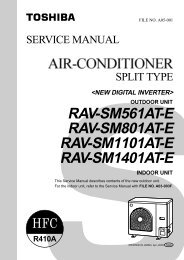
<strong>Super</strong> <strong>Multi</strong> <strong>System</strong><br />
HFC R407C<br />
A90-0233<br />
Service Manual<br />
Air Conditioner - <strong>Multi</strong> Split Type <strong>System</strong>
Contents<br />
Introduction<br />
Precautions .......................................................................................................................................... 4<br />
Components ......................................................................................................................................... 6<br />
Outline of control system ...................................................................................................................... 9<br />
Parts specification<br />
Outdoor unit - general ......................................................................................................................... 12<br />
Outdoor unit - refrigeration parts ......................................................................................................... 13<br />
Outdoor unit - inverter assembly ......................................................................................................... 14<br />
<strong>Multi</strong> Controller - general .................................................................................................................... 15<br />
Construction views<br />
Outdoor unit ........................................................................................................................................ 16<br />
<strong>Multi</strong> Controller ................................................................................................................................... 17<br />
Wiring diagram<br />
Outdoor unit ........................................................................................................................................ 18<br />
<strong>Multi</strong> Controller ................................................................................................................................... 20<br />
Refrigeration schematic<br />
Outdoor unit ........................................................................................................................................ 21<br />
Normal operation - heat mode ............................................................................................................ 22<br />
Normal operation - cool mode ............................................................................................................ 23<br />
Simultaneous operation - mainly heat ................................................................................................. 24<br />
Simultaneous operation - mainly cool ................................................................................................. 25<br />
Diagnostic procedure<br />
Diagnostic - outdoor unit ..................................................................................................................... 26<br />
Diagnostic - <strong>Multi</strong> Controller unit ......................................................................................................... 32<br />
Fault code display<br />
Self-diagnostic function ...................................................................................................................... 34<br />
Troubleshooting<br />
Fault code table .................................................................................................................................. 36<br />
Diagnostic procedure for check code ................................................................................................. 37<br />
Control features ..................................................................................................................................... 63<br />
Valve and sensor function and operation<br />
<strong>Multi</strong> Controller valve function and operation ...................................................................................... 65<br />
Outdoor unit valve functions ............................................................................................................... 66<br />
Manual operation of valves ................................................................................................................. 67<br />
Sensor and switch operation .............................................................................................................. 68<br />
Refrigeration pipe installation<br />
Leak test ............................................................................................................................................. 69<br />
Vacuuming ......................................................................................................................................... 70<br />
Charging ............................................................................................................................................. 71<br />
Piping ................................................................................................................................................. 72<br />
Additional refrigerant .......................................................................................................................... 73<br />
Service parts list<br />
Outdoor unit exploded views .............................................................................................................. 74<br />
Inverter exploded view ........................................................................................................................ 77<br />
<strong>Multi</strong> Controller exploded view ............................................................................................................ 78<br />
<strong>Multi</strong> Controller electrical parts ........................................................................................................... 79<br />
3
4<br />
Introduction<br />
Precautions<br />
Please read these instructions carefully before starting the installation.<br />
This equipment should only be installed by suitably trained operatives.<br />
In all cases ensure safe working practice: Observe precautions for persons in the vicinity of the works.<br />
Ensure that all local, national and international regulations are satisfied.<br />
Check that the electrical specifications of the unit meet the requirements of the site.<br />
Carefully unpack the equipment, check for damage or shortages. Please report any damage immediately.<br />
Model MAR-F105HTM8-PE complies with the following EU Directives:<br />
73/23/EEC (Low Voltage Directive), 89/336/EEC (Electromagnetic Compatibility) and 97/23/EC (Pressure<br />
Equipment Directive). Accordingly, they are designated for use in commercial and industrial environments.<br />
97/23/EC Pressure Equipment Directive information<br />
Conformity assessment procedure: Module D1<br />
Pressure equipment:<br />
Compressor, category II, Module A1 Liquid receiver, category II<br />
Accumulator, category I High pressure switch, category II, Module A1<br />
Notified body for inspection and quality assurance systems: BSI, Maylands Avenue, Hemel Hempstead,<br />
WP2 4SQ, UK.<br />
Avoid installation in the following locations:<br />
Where there is danger of flammable gas leakages.<br />
Where there are high concentrations of oil.<br />
Where the atmosphere contains an excess of salt (as in coastal areas). The air conditioner is prone to<br />
failure when used under this condition unless special maintenance is provided.<br />
Where the airflow from the outdoor unit may cause annoyance.<br />
Where the operating noise of the outdoor unit may cause annoyance.<br />
Where the foundation is not strong enough to fully withstand the weight of the outdoor unit.<br />
Where the water drainage may cause a nuisance or a hazard when frozen.<br />
Where strong winds may blow against the air outlet of the outdoor unit.<br />
Precautions for R407C outdoor units<br />
R407C outdoor units use synthetic oils which are extremely hygroscopic. Therefore ensure that the<br />
refrigerant system is NEVER exposed to air or any form of moisture.<br />
Mineral oils are unsuitable for use in these units and may lead to premature system failure.<br />
Use only equipment which is suitable for use with R407C. Never use equipment which has been used<br />
with R22.<br />
R407C should only be charged from the service cylinder in the liquid phase. It is advisable to use a<br />
gauge manifold set equipped with a liquid sight glass fitted in the centre (entry) port.
Introduction<br />
Precautions<br />
Precautions for R-407C outdoor units<br />
Liquid receiver fusible plug<br />
In the event of the system being subjected to abnormal conditions it is protected by a fusible plug,<br />
positioned on the liquid receiver, within the outdoor unit. It is rated to fail at 70°C.<br />
Position of<br />
fusible plug<br />
<strong>System</strong> pressure measurement<br />
To measure the system’s high and low pressures, connect a gauge manifold to the corresponding access<br />
port as indicated below.<br />
Low pressure<br />
access port<br />
High pressure<br />
access port<br />
Explanation of <strong>Toshiba</strong> serial number<br />
A serial label is attached to all <strong>Toshiba</strong> air conditioning units. Located on the label is an 8-digit number,<br />
which represents the month, year and batch number of the manufactured unit. A breakdown of the 8-digit<br />
number is defined below.<br />
2 4 4 8 0 0 0 1<br />
� � �<br />
Year of<br />
manufacture<br />
2001 = 1<br />
2002 = 2<br />
2003 = 3<br />
Month of<br />
manufacture<br />
41 = Jan.<br />
42 = Feb.<br />
43 = Mar.<br />
44 = Apr.<br />
45 = May<br />
46 = Jun.<br />
47 = Jul.<br />
48 = Aug.<br />
49 = Sep.<br />
50 = Oct.<br />
51 = Nov.<br />
52 = Dec.<br />
Site of<br />
manufacture<br />
8 = Plymouth<br />
}<br />
Model batch serial number<br />
5
Components - 3 pipe system<br />
1. Outdoor unit<br />
Model name Inverter unit<br />
MAR-F105HTM8-PE 10 HP<br />
2. <strong>Multi</strong> Controllers<br />
6<br />
Introduction<br />
Components<br />
Model name No. of indoor units connectable<br />
RBM-Y1034F-PE 3<br />
RBM-Y1044F-PE 4<br />
3. Interface control kit<br />
Model name Requirement<br />
RBC-16DIF1-PE 3 or 4 <strong>Multi</strong> Controllers used on a system<br />
Combination of <strong>Multi</strong> Controllers, indoor units and interface kits<br />
No. of No. of 3-way No. of 4-way No. of<br />
indoor units <strong>Multi</strong> Controllers <strong>Multi</strong> Controllers interface kits<br />
1-8 1-2 <strong>Multi</strong> Controllers 0<br />
9 3 0 1<br />
10 2 1 1<br />
11 1 2 1<br />
12 0 3 1<br />
13 3 1 2<br />
14 2 2 2<br />
15 1 3 2<br />
16 0 4 2
Operating conditions of the unit are as follows:<br />
Introduction<br />
Operating conditions<br />
Outdoor temperature -5 ~ 43°C Cooling<br />
-15 ~ 21°C Heating<br />
Room temperature 18 ~ 32°C Cooling<br />
15 ~ 29°C Heating<br />
Room humidity
8<br />
Introduction<br />
<strong>Super</strong> multi system basic components<br />
3-pipe heat pump with simultaneous heating and cooling<br />
This system allows separate operation of each indoor unit in either heating or cooling simultaneously.<br />
3 pipes<br />
3-pipe<br />
outdoor unit<br />
T-pieces<br />
<strong>Multi</strong> Controller<br />
2 pipes<br />
Indoor unit remote controller requesting cooling<br />
Cooling operation<br />
Indoor unit remote controller requesting heating<br />
Heating operation<br />
Indoor units<br />
Remote controller
Introduction<br />
Outline of control system<br />
The refrigerant and electrical systems of the <strong>Super</strong> <strong>Multi</strong> air conditioner are controlled by the <strong>Multi</strong><br />
Controller and the outdoor unit microprocessors.<br />
All RAV heat pump, R-407C, 4/5 series indoor units are compatible with the <strong>Super</strong> <strong>Multi</strong> system, i.e. 1~5 HP.<br />
For system operation, initially the microprocessor in each indoor unit calculates the difference between the<br />
current room temperature (TA) and the requested temperature which has been set on the remote<br />
controller. A demand signal is determined and transmitted to the <strong>Multi</strong> Controller microprocessor in the<br />
form of operation commands (i.e. ON/OFF, cooling or heating operation mode, operation demand frequency).<br />
The <strong>Multi</strong> Controller microprocessor receives operation commands from all indoor units connected,<br />
calculates the accumulative operation command and transmits this information to the outdoor unit interface<br />
microprocessor.<br />
The interface microprocessor calculates the capacity required for heating or cooling and determines the<br />
operation mode of the outdoor unit and the actual frequency of the compressor.<br />
Control system diagram<br />
Indoor unit 1-A<br />
Fan<br />
Temp. sensor (TA)<br />
Drain pump<br />
Indoor unit microprocessor<br />
Remote controller<br />
1 - B<br />
1 - C<br />
1 - D<br />
2 - A<br />
2 - B<br />
2 - C<br />
2 - D<br />
<strong>Multi</strong> Controller 1<br />
Capacity rank<br />
setting switch<br />
Temp. sensor<br />
Pulse modulating<br />
valve<br />
<strong>Multi</strong> Controller microprocessor<br />
Display LED<br />
2-way valve<br />
<strong>Multi</strong> Controller 2<br />
<strong>Multi</strong> Controller microprocessor<br />
Protection unit<br />
Comp. sensor<br />
Temp. sensor<br />
Fan<br />
Outdoor unit<br />
Pulse modulating<br />
valve<br />
Interface microprocessor<br />
D.O.L. compressor<br />
Display LED<br />
2-way valve<br />
4-way valve<br />
Communication<br />
PCB<br />
Protection<br />
unit<br />
Inverter<br />
compressor<br />
IPDU Inverter<br />
Power<br />
supply<br />
9
10<br />
Introduction<br />
Components<br />
Setting of indoor unit capacity codes<br />
The setting of the indoor unit capacities is important. Set the correct indoor unit code numbers<br />
according to the indoor unit capacity. The capacities are set by the rotary switches on the printed<br />
circuit board switch A (unit A), switch B (unit B), switch C (unit C) and switch D (unit D).<br />
During manufacture, the indoor capacity selection switches are set at ‘0’.<br />
Record the indoor capacity codes, indoor unit model names and locations in the installation manual,<br />
and on the wiring diagram on the electrical panel cover.<br />
Example: Room A Room B Room C<br />
Capacity 16 Capacity 16 Capacity 26<br />
Indoor unit Capacity No connection 10 13 16 20 26 36 46<br />
Code number 0 2 3 4 5 6 8 10<br />
(Example: Model RAV-364UH-PE, capacity = 36)<br />
<strong>Multi</strong> Controller PCB<br />
MCC-1210<br />
Capacity select switches<br />
<strong>Multi</strong>ple indoor units may be connected to each outdoor unit, providing the total indoor code does not<br />
exceed the limits shown below.<br />
Combination of <strong>Multi</strong> Controllers and indoor units<br />
Number of Maximum No. of Indoor unit diversity Maximum system code Maximum code per<br />
<strong>Multi</strong> Controllers indoor units <strong>Multi</strong> Controller<br />
1 4 135% 27 27<br />
2 8 160% 32 27<br />
3 12 27 (13*)<br />
4 16 13<br />
Example of systems with maximum possible code:<br />
Outdoor unit<br />
Interface kit<br />
<strong>Multi</strong> Controller [code]<br />
(Max. system code)<br />
OD OD OD OD OD<br />
DIF DIF<br />
DIF<br />
27 27 6 27 26 13 6 13 6 20 27 13 8 13 8 13 8 13 8<br />
(27) (32) (32)<br />
(32)
Indoor units<br />
Introduction<br />
Components<br />
Type Appearance Model name Capacity code on<br />
<strong>Multi</strong> Controller<br />
Cassette (4-way) RAV-164UH-PE 4<br />
RAV-264UH-PE 6<br />
RAV-364UH-PE 8<br />
RAV-464UH-PE 10<br />
Cassette (2-way) RAV-104TUH-1-PE 2<br />
RAV-134TUH-1-PE 3<br />
RAV-164TUH-1-PE 4<br />
Built-In Horizontal<br />
RAV-104SBH-PE 2<br />
RAV-164BH-PE 4<br />
RAV-264BH-PE 6<br />
RAV-364BH-PE 8<br />
RAV-464BH-PE 10<br />
Ceiling Suspended RAV-134CH/CHR-PE 3<br />
RAV-164CH/CHR-PE 4<br />
RAV-264CH/CHR-PE 6<br />
RAV-364CH/CHR-PE 8<br />
RAV-464CH/CHR-PE 10<br />
High Wall RAV-105KH-E 2<br />
RAV-135KH-E 3<br />
RAV-165KH-E 4<br />
RAV-265KH-E 5<br />
High Wall RAV-264KH-PE 6<br />
Built-In Vertical RAV-104NH-PE 2<br />
RAV-134NH-PE 3<br />
RAV-164NH-PE 4<br />
RAV-264NH-PE 6<br />
Floor Mounted RAV-164SH/SHR-PE 4<br />
RAV-264SH/SHR-PE 6<br />
11
12<br />
Parts specification<br />
Outdoor unit<br />
Specification of 3-pipe, heat recovery outdoor unit<br />
Model name MAR-F105HTM8-PE<br />
Cooling capacity kW 25.0 (28.0)<br />
Heating capacity kW 28.0 (31.5)<br />
Power supply<br />
Cooling<br />
380-415 V, 3 phase, 50 Hz<br />
Operating current A 17.4 (19.1)<br />
Power consumption kW 11.8 (12.8)<br />
EER 2.11 (2.19)<br />
Power factor<br />
Heating<br />
% 98 (97)<br />
Operating current A 17.7 (15.5)<br />
Power consumption kW 11.8 (10.5)<br />
COP 2.37 (3.0)<br />
Power factor % 96 (98)<br />
Starting current A 60<br />
Starting method Direct<br />
Sound level Sound pressure dB 58<br />
Sound power dB(A) 70<br />
Dimensions (H x W x D) mm 1700 x 990 x 790<br />
Net weight kg 285<br />
Colour Silky Shade (Munsell 1-Y8.5/0.5)/RAL 1013 (DE ~9)<br />
Compressor Type Hermetically sealed (twin scroll)<br />
Oil (volume) ml Polyolester NISSEKI RB74AF 74VG (7000)<br />
Crankcase heater Internal type<br />
Motor output kW 7.5<br />
Fan assembly Fan Propeller fan<br />
Motor output kW 0.4<br />
Air flow volume m3 /h 10,000<br />
Refrigeration (charged weight) kg R-407C (19)<br />
Piping connection Liquid mm 15.9 (flare connection)<br />
Discharge gas mm 19.0 (flare connection)<br />
Suction gas mm 28.6 (brazing connection)<br />
Max. equivalent piping length m 120<br />
Max. actual piping length m 100<br />
Max. piping head m 50: when the outdoor unit is installed above<br />
m 20: when the outdoor unit is installed below<br />
Suction accumulator case heater W 29 (240 V AC)<br />
Notes:<br />
1. Specifications are subject to change without notice.<br />
2. The specification shown in ( ) denotes operation with an indoor unit load diversity of 135%.<br />
3. Operating conditions:<br />
Outdoor temperature °C Cooling -5 to 43<br />
Heating -15 to 21<br />
Room temperature °C Cooling 18 to 32<br />
Heating 15 to 29<br />
4. Sound level: 1 m horizontal from centre.<br />
1.5 m vertical from base.
Parts specification<br />
Outdoor unit<br />
Specification of outdoor unit refrigeration cycle parts<br />
Parts description MAR-F105HTM8-PE<br />
Compressor model Model name MG1300CW-20<br />
Motor type 3-phase induction motor<br />
Power supply 380-415 V, 3 phase, 50 Hz<br />
Output kW 7.5<br />
Pole 2/2 (inverter side/non-inverter side)<br />
Coil resistance Ω 1.49/2.51 (inverter side/non-inverter side)<br />
Compressor oil name Polyolester NISSEKI RB68AF VG 74<br />
Amount of oil ml 7,000<br />
Fan motor Model name STF-200-350A<br />
Motor type 1-phase, induction type<br />
Power supply 220-240 V, 1 phase, 50 Hz<br />
Output kW 0.4<br />
Supply current A 3.2 ~ 3.5<br />
Pole 6<br />
Protective device Operation °C 145 ± 5<br />
(Relay) Reset °C 86 ± 15<br />
High pressure switch Model name ACB-JB128<br />
Inverter side Operating pressure Operation MPa 3.2<br />
Reset MPa 2.55<br />
High pressure switch Model name ACB-JA64<br />
Fixed side Operating pressure Operation MPa 3.2<br />
Reset MPa 2.55<br />
Low pressure switch Model name 20PS-1<br />
Operating pressure Operation MPa 0.025<br />
Reset MPa 0.15<br />
4-way valve CHV-0712, coil AC240 V<br />
Liquid tank l (RSH 12) 12<br />
Accumulator l (BT9-1 1/8)<br />
Check valve Model name YCV5-3SPTF-1<br />
Maximum pressure MPa 3.3<br />
Check joint Model name R-407C type<br />
Maximum pressure MPa 3.53<br />
Expansion valve EXV-V-E80HTF-9WS<br />
Compressor heater (Internal within the compressor)<br />
Accumulator heater W 29 (240 V AC)<br />
Pressure sensor Model name: NTP-Q250TF-2<br />
Input voltage: DC12 V<br />
Discharge temperature sensor 25°C = 50 kΩ<br />
Output voltage: DC 0.5 - 4.5 V<br />
50°C = 18.1 kΩ<br />
100°C = 3.35 kΩ<br />
Suction temperature sensor/ 0°C = 34.6 kΩ<br />
outdoor air temperature sensor 25°C = 10 kΩ<br />
50°C = 3.4 kΩ<br />
Pulse modulating valve (Cooling bypass PMV1) EV18RC1, coil DC 12 V<br />
Pulse modulating valve (PMV2) EV23RC2, coil DC 12 V<br />
2-way valve (SV1, SV2, SV4, SV5, SV16, SV17) NEV202DXF, coil AC 240 V<br />
2-way valve (SV13, SV14, SV15) RP100-03, coil AC 240 V<br />
Note:<br />
Specifications are subject to change without notice.<br />
13
14<br />
Parts specification<br />
Outdoor unit<br />
Specification of outdoor unit inverter assembly parts<br />
Model name MAR-F105HTM8-PE<br />
Power supply 380-415 V, 3 phase, 50 Hz<br />
PC board assembly PCB (IPDU) MCC-1342<br />
PC board assembly PCB (noise filter) MCC-1366<br />
PC board assembly PCB (interface) MCC-1223<br />
PC board assembly PCB (communication) MCC-1387<br />
Fan motor capacitor 8 µF/450 V AC<br />
Electrolytic capacitor 2200 µF/400 V<br />
Power supply terminal plate L1, L2, L3 600 V AC, 60 A, 3 pole<br />
Transformer Interface TT01<br />
Magnetic contactor Inverter side FMCa - 1S<br />
Magnetic contactor Fixed side FC - 3<br />
Reactor CH - 25 - 2FK<br />
Fuse 6 A 500 V AC<br />
Fuse 20 A 600 V AC<br />
Fuse 3.15 A 250 V AC<br />
Fuse 6.3 A 250 V AC<br />
Fuse 20 A 250 V AC<br />
Fuse 10 A 250 V AC<br />
Thermistor (PTC)<br />
Relay 15 A, 240 V AC<br />
Note:<br />
Specifications are subject to change without notice.
Parts specification<br />
<strong>Multi</strong> Controller unit<br />
Specification of 3-pipe <strong>Multi</strong> Controller parts<br />
Model name RBM-Y1034F-PE RBM-Y1044F-PE<br />
Pulse modulating valve EV23RC7, coil DC 12 V<br />
Temperature sensor At 0°C = 32.8 kΩ, 25°C = 10 kΩ, 50°C = 3.6 kΩ<br />
Float switch FS-085-0031<br />
PC board assembly PCB MCC-1222<br />
Power supply transformer Model name FT69<br />
Specification Primary side: AC 240 V, secondary side: AC 12 V<br />
Relay (PC board) G2R-117P, coil DC 12 V<br />
Heater 10.4 W/m<br />
50 W 65 W<br />
Thermal fuse for heater Cut out at 119°C<br />
Heater fuse T1A<br />
Discharge gas side 2-way valve RP100-03, coil AC 240 V<br />
Suction gas side 2-way valve REV-1506DXFQ6, coil AC 240 V<br />
2-way valve NEV202DXF-AC 240 V<br />
2-way valve NEV603DXF-AC 240 V<br />
Note:<br />
Specifications are subject to change without notice.<br />
15
MAR-F105HTM8-PE<br />
Dimensional drawings<br />
1700<br />
16<br />
1582<br />
110 90<br />
700<br />
88<br />
4-60 x 150 slot<br />
(for transport)<br />
All dimensions in mm<br />
Fixing bolt pitch<br />
700<br />
990<br />
568<br />
500<br />
Slot pitch<br />
Details of piping connections<br />
Construction view<br />
4-15 x 20 (Slot)<br />
68<br />
60<br />
Outdoor unit<br />
114<br />
Fixing bolt positions<br />
755 790<br />
601<br />
315<br />
275<br />
80<br />
630<br />
80<br />
Pipe outlet<br />
(bottom)<br />
Knock outs on<br />
both sides of unit<br />
Grounding part of bottom plate<br />
Grounding part of bottom plate<br />
Foundation dimensions<br />
750<br />
3-ø 20 cable gland knock outs<br />
ø 32 cable gland knock outs<br />
ø 25 cable gland knock outs<br />
Refrigerant pipe connecting port<br />
(Gas suction side) braze connection (ø 28.6)<br />
Refrigerant pipe connecting port<br />
(Liquid side) flare connection (ø 15.9)<br />
Refrigerant pipe connecting port (gas<br />
discharge side) flare connection (ø 19.0)<br />
4 - ø 25<br />
drain holes
Construction view<br />
<strong>Multi</strong> Controller<br />
Model A B C D E F<br />
RBM-Y1034F-PE 460 300 - 90 - 90<br />
RBM-Y1044F-PE 530 370 90 90 90 90<br />
All dimensions are in mm<br />
300<br />
110<br />
Electric parts box<br />
A<br />
C D<br />
E F<br />
90 55<br />
90 55<br />
80 50<br />
Refrigerant pipe<br />
connection (brazing)<br />
Liquid side ø 12.7<br />
300<br />
2 notches for<br />
hanging bolts<br />
(12 x 21)<br />
Refrigerant pipe<br />
connection (brazing)<br />
Gas side ø 19<br />
2 slots for<br />
hanging bolts<br />
(12 x 52)<br />
3-pipe:<br />
RBM-Y1034F/Y1044F-PE<br />
Connection (brazing)<br />
Liquid side ø 15.9<br />
Refrigerant pipe<br />
connection (brazing)<br />
Delivery gas side ø 19<br />
Refrigerant pipe<br />
connection (brazing)<br />
Suction gas side ø 28.6<br />
Wiring knockouts<br />
6 x ø 20<br />
17
MAR-F105HTM8-PE<br />
18<br />
Wiring diagrams<br />
Outdoor unit
Wiring diagrams<br />
Outdoor unit<br />
19
20<br />
Wiring diagram<br />
<strong>Multi</strong> Controllers<br />
3-pipe <strong>Multi</strong> Controller (RBM-Y1034F-PE, RBM-Y1044F-PE)<br />
Symbol Part Name<br />
PMVA, B, C, D Pulse modulating valve<br />
Th A, B, C, D, X Temperature sensor<br />
Tr Power transformer<br />
CS Float switch<br />
H Heater<br />
MS Reset switch<br />
F Fuse (T1A)<br />
SVD (A), (B), (C), (D) Electrically operated valve for discharge gas side<br />
SVD (A), (B), (C), (D) Electrically operated valve for suction gas side<br />
SVDD Electrically operated valve for increasing pressure<br />
SVSS Electrically operated valve for decreasing pressure<br />
SVH Electrically operated valve for superheat control<br />
LD 101, 102, 103, 104 Fault indicator LED<br />
Parts layout<br />
Control PC board<br />
Terminal plate<br />
Capacity rank<br />
setting<br />
A B C D<br />
7-segment LED<br />
Trans<br />
Display<br />
selector switch<br />
Reset<br />
switch<br />
Indoor<br />
unit A<br />
Indoor<br />
unit B<br />
Spark<br />
killer<br />
Indoor<br />
unit C<br />
Indoor<br />
unit D<br />
Outdoor<br />
unit<br />
The dashed lines indicate wiring on site.<br />
and indicate terminal blocks, and numbers within them are<br />
1234 terminal numbers.<br />
1234<br />
indicates a printed circuit board.<br />
The frame indicates the product body.<br />
RBM-Y1034F-PE does not have PMVD, SVD(D), SVS(D), ThD or the<br />
connection block for indoor unit D.<br />
The capacity rank code setting for unit D is to be set to “0”.
Refrigeration piping schematic diagram<br />
Outdoor unit<br />
21
22<br />
Refrigeration piping schematic diagram<br />
Normal operation - heat mode<br />
Key:<br />
High pressure gas<br />
Low pressure gas<br />
High pressure liquid<br />
Low pressure liquid
Refrigeration piping schematic diagram<br />
Normal operation - cool mode<br />
Key:<br />
High pressure gas<br />
Low pressure gas<br />
High pressure liquid<br />
Low pressure liquid<br />
23
24<br />
Refrigeration piping schematic diagram<br />
Simultaneous operation - mainly heat<br />
Key:<br />
High pressure gas<br />
Low pressure gas<br />
High pressure liquid<br />
Low pressure liquid
Refrigeration piping schematic diagram<br />
Simultaneous operation - mainly cool<br />
Key:<br />
High pressure gas<br />
Low pressure gas<br />
High pressure liquid<br />
Low pressure liquid<br />
25
26<br />
Diagnostic procedure<br />
Outdoor unit<br />
MAR-F104HTM8-PE, 3-pipe outdoor unit<br />
Malfunction judgement is performed using the self-diagnostic function of the outdoor unit. The combination<br />
of the display switches (SW1, SW2) and the LEDs (LD 71~LD 74) indicates the diagnostic details.<br />
Located on the electrical inverter cover is a transparent window, which allows the 7-segment LED to be<br />
viewed while the unit is in operation.<br />
The transparent window has access holes to allow the adjuster pen, which is attached to the window,<br />
access to alter the setting of the display switch SW1 and SW2 while the unit is running.<br />
A slit is positioned at one end of the pen to locate onto the rotary switch.<br />
The adjuster pen can also be used to push switches SW3 and SW4 during the diagnostic procedure<br />
check.<br />
A crimp connector is located on the other end of the adjuster pen. This connector can be used to ‘short’<br />
TP1 or TP2 connectors when performing manual operation of the outdoor valves.<br />
No other component other than that supplied must be used to adjust the rotary switches. Failure to do<br />
so may result in damage to the unit, malfunction or risk of electric shock.
Diagnostic procedure<br />
Outdoor unit<br />
1. Communication serial signals and the system operating status are displayed by changing display<br />
switch SW2.<br />
Display Display Indication 7-segment LED display<br />
switch switch LD 71 LD 72 LD73 LD74<br />
SW1 SW2<br />
position position<br />
0 0 Sending/receiving status of Between Between Between Non-inverter<br />
interface control board serial M/C (1) M/C (2) inverter compressor<br />
signal Sending Not sending Abnormal [E]<br />
only [S] or receiving<br />
[ ]<br />
Receiving Sending and Normal [0]<br />
only [J] receiving [0]<br />
1 Operating instruction Operating Heating [H], Simultaneous ---------- --------from<br />
M/C (1) mode cooling/heating [HC],<br />
Cooling [C], Stop [ ]<br />
2 Instruction Heating frequency [00-1F] Cooling frequency [00-1F]<br />
frequency (Refer to conversion table 2) (Refer to conversion table 2)<br />
3 Outdoor unit Operating Heating [H], Cooling [0C], ---------- --------operating<br />
condition mode Simultaneous heating [Hc]<br />
Defrost [J0], Simultaneous<br />
cooling [hC]<br />
4 M/C Frequency ---------- --------operation<br />
release<br />
Off: [0] No: [0]<br />
1 unit: [1]<br />
2 unit: [2]<br />
Yes: [1]<br />
5 Operating instruction Operating Heating [H], Simultaneous ---------- --------from<br />
M/C (2) mode cooling/heating [HC],<br />
Cooling [C], Stop [-]<br />
6 Instruction Heating frequency [00-1F] Cooling frequency [00-1F]<br />
frequency (Refer to conversion table 2) (Refer to conversion table 2)<br />
9 Inverter operation status Normal Operating ---------- ----------<br />
[C] frequency<br />
[0-F],<br />
Abnormal (Refer to<br />
[E] table 3)<br />
10 Operating instruction to Normal Operating ---------- --------inverter<br />
from interface [C] frequency<br />
control board [0-F],<br />
Abnormal (Refer to ---------- ----------<br />
[E] table 3)<br />
11 Power supply frequency 50 Hz [5]<br />
60 Hz [6]<br />
[0] ---------- ----------<br />
27
28<br />
Diagnostic procedure<br />
Outdoor unit<br />
2. Display code conversion table - instruction frequency from <strong>Multi</strong> Controller.<br />
Display<br />
code<br />
00 01 02 03 04 05 06 07 08 09 0A 0B 0C 0D 0E 0F<br />
Frequency<br />
conversion<br />
value (Hz)<br />
0 0 0 3.9 6.9 10.0 13.0 16.2 19.3 22.4 25.5 28.6 31.7 34.8 37.9 41.0<br />
Display<br />
code<br />
10 11 12 13 14 15 16 17 18 19 1A 1B 1C 1D 1E 1F<br />
Frequency<br />
conversion<br />
value (Hz)<br />
44.1 47.2 50.3 53.4 56.5 59.6 62.7 65.8 68.9 72.0 75.1 78.2 81.3 84.4 87.5 90.0<br />
3. Display code conversion table - operating frequency of inverter compressor<br />
Display<br />
code<br />
0 3 4 5 6 7 8 9 A B C D E F<br />
Frequency<br />
conversion<br />
value (Hz)<br />
0 30.5 38.3 41.9 45.5 53.3 61.0 68.8 76.0 83.8 91.6 102.9 110.7 121.5<br />
4. PMV opening information is displayed<br />
Display Display Indication 7-segment LED display<br />
switch switch LD 71 LD 72 LD 73 LD 74<br />
SW1 SW2<br />
position position<br />
1 2 PMV1 opening [P] [1] Displays the degree of PMV<br />
opening (0 - 240) as a<br />
hexadecimal code:<br />
3 PMV2 opening [P] [2] [00] : Closed, [F0] : Fully open<br />
5. Malfunction information is displayed, refer to fault code section for details<br />
Display Display Indication 7-segment LED display<br />
switch switch LD 71 LD 72 LD 73 LD 74<br />
SW1 SW2<br />
position position<br />
2 0 Check code [E] Outdoor unit: [r] Refer to fault code section for<br />
display for the M/C (1): [1] details (page 36)<br />
outdoor unit,<br />
M/C (1), M/C (2)<br />
M/C (2): [2]
Diagnostic procedure<br />
Outdoor unit<br />
6. The indoor unit capacity rank setting is displayed.<br />
Display Display Indication 7-segment LED display<br />
switch switch LD 71 LD 72 LD 73 LD 74<br />
SW1 SW2<br />
position position<br />
3 0 Outdoor unit HP [9] 8 HP [8], 10 HP [A] [H] [P]<br />
1 Capacity rank of Unit A [A] Displays the code number of the<br />
2 indoor unit Unit B [b] indoor unit registered to each M/C.<br />
3 connected to Unit C [C]<br />
4 M/C (1) Unit D [d] Refer to the table below (7) for<br />
5 Capacity rank of Unit A [A] indoor unit model capacity rank.<br />
6 indoor unit Unit B [b]<br />
7 connected to Unit C [C]<br />
8 M/C (2) Unit D [d]<br />
7. Indoor unit code No. conversion table<br />
Code No. 0 2 3 4 5 6 8 10<br />
Capacity rank No correction 10 13 16 20 26 36 46<br />
(Indoor unit model example: Model RAV-364UH-PE, capacity rank = 36)<br />
8. Sensor temperature display<br />
Display Display Indication 7-segment LED display<br />
switch switch LD 71 LD 72 LD 73 LD 74<br />
SW1 SW2<br />
position position<br />
4 0 Pressure sensor data [P] [d] Refer to table 9 conversion chart<br />
1 ThD1 sensor data [d] [1] Refer to table 10 conversion chart<br />
2 ThD2 sensor data [d] [2]<br />
3 ThS sensor data [S] [1] Refer to table 11 conversion chart<br />
4 TE sensor data [h] [E]<br />
5 TO sensor data [h] [0]<br />
29
9. Outdoor unit - pressure sensor data<br />
30<br />
Diagnostic procedure<br />
Outdoor unit<br />
Display Pressure Display Pressure Display Pressure Display Pressure<br />
(kgf/cm 2 G) (kgf/cm 2 G) (kgf/cm 2 G) (kgf/cm 2 G)<br />
17 0.0 67 11.0 96 17.5 C6 24.0<br />
1E 1.0 6B 11.5 9A 18.0 C9 24.5<br />
25 2.0 6E 12.0 9E 18.5 CD 25.0<br />
2D 3.0 72 12.5 A1 19.0 D1 25.5<br />
34 4.0 76 13.0 A5 19.5 D4 26.0<br />
3B 5.0 79 13.5 A9 20.0 D8 26.5<br />
43 6.0 7D 14.0 AC 20.5 DC 27.0<br />
4A 7.0 81 14.5 BD 21.0 DF 27.5<br />
51 8.0 84 15.0 B4 21.5 E3 28.0<br />
58 9.0 88 15.5 B7 22.0 E7 28.5<br />
5C 9.5 8B 16.0 BB 22.5 EA 29.0<br />
60 10.0 8F 16.5 BE 23.0 EE 29.5<br />
63 10.5 93 17.0 C2 23.5 F2 30.0<br />
These are sample displays. intermediate displays to those above are possible.<br />
10. Outdoor unit - ThD1 and ThD2 sensor data<br />
Display Temp. °C Display Temp. °C Display Temp. °C Display Temp. °C<br />
05 -5.0 28 40.0 7C 85.0 C6 130.0<br />
07 0.0 30 45.0 87 90.0 CB 135.0<br />
09 5.0 38 50.0 90 95.0 D0 140.0<br />
0C 10.0 41 55.0 9A 100.0<br />
0F 15.0 4A 60.0 A2 105.0<br />
12 20.0 54 65.0 AB 110.0<br />
17 25.0 5E 70.0 B2 115.0<br />
1C 30.0 68 75.0 B9 120.0<br />
22 35.0 72 80.0 C0 125.0<br />
These are sample displays. Intermediate displays to those above are possible.<br />
Display [00] signifies sensor open circuit.<br />
11. Outdoor unit - ThS, TE, TO sensor data<br />
Display Temp. °C Display Temp. °C Display Temp. °C Display Temp. °C<br />
2A -20.0 7C 9.0 A2 22.0 C0 35.0<br />
36 -15.0 7F 10.0 A5 23.0 C2 36.0<br />
42 -10.0 82 11.0 A7 24.0 C4 37.0<br />
51 -5.0 85 12.0 AA 25.0 C6 38.0<br />
60 0.0 88 13.0 AC 26.0 C8 39.0<br />
63 1.0 8B 14.0 AF 27.0 C9 40.0<br />
66 2.0 8E 15.0 B1 28.0 D1 45.0<br />
69 3.0 91 16.0 B3 29.0 D8 50.0<br />
6C 4.0 94 17.0 B6 30.0 DE 55.0<br />
6F 5.0 97 18.0 B8 31.0 E3 60.0<br />
73 6.0 9A 19.0 BA 32.0 E7 65.0<br />
76 7.0 9C 20.0 BC 33.0 EA 70.0<br />
79 8.0 9F 21.0 BE 34.0<br />
These are sample displays. Intermediate displays to those above are possible.<br />
Display [00] signifies sensor open circuit.
12. Outdoor unit circuit test procedure<br />
Diagnostic procedure<br />
Outdoor unit circuit test procedure<br />
These systems have a feature which enables them to check that the wiring and piping connections<br />
are aligned with each other. This is carried out by allowing refrigerant to flow to one indoor unit at a<br />
time and monitoring that indoor unit’s coil sensor for a corresponding drop in temperature. Each<br />
indoor unit is tested in turn and where two <strong>Multi</strong> Controllers are installed each <strong>Multi</strong> Controller is tested<br />
in turn.<br />
This test would normally be used at the commissioning stage.<br />
Procedure for initialising the circuit test.<br />
1. Turn the power off.<br />
2. Ensure the capacity codes are set correctly, capacity switches set to ‘0’ are not tested.<br />
3. Put the outdoor display switches SW1 and SW2 to 9 and <strong>Multi</strong> Controller(s) display switch to 6.<br />
4. Turn the power back on.<br />
5. Set all the remote controllers to cool mode and 29°C.<br />
6. Press the on/off button to start all the indoor units (the outdoor LEDs show ‘1020’).<br />
7. Press the outdoor unit switch SW3, and hold for 3 seconds.<br />
8. The system is now in self-testing (all 8 LEDs will be flashing rapidly).<br />
9. The system will stop at the end of the test.<br />
In the event of cross wiring/piping the system will indicate which units are faulty, see table below:<br />
Outdoor display switch SW1 and SW2 set to position 9.<br />
One and two <strong>Multi</strong> Controllers<br />
Display <strong>Multi</strong> Controller Fault<br />
1020 All None<br />
1A20 1 Unit A<br />
1B20 Unit B Units that are indicated<br />
1C20 Unit C failed the test<br />
1D20 Unit D<br />
102A 2 Unit A<br />
102B Unit B<br />
102C Unit C<br />
102D Unit D<br />
Three or more <strong>Multi</strong> Controllers<br />
Display <strong>Multi</strong> Controller Fault<br />
1020 All None<br />
1A20 1 Unit A or B<br />
1B20 Unit C or D Units that are indicated<br />
1C20 2 Unit A or B failed the test<br />
1D20 Unit C or D<br />
102A 3 Unit A or B<br />
102B Unit C or D<br />
102C 4 Unit A or B<br />
102D Unit C or D<br />
31
32<br />
Diagnostic procedure<br />
<strong>Multi</strong> Controller<br />
The combination of the display switch and the four 7-segment LEDs (LD 101-LD 104) indicates the<br />
diagnostic details.<br />
7 segment LED display<br />
Unit B Unit D<br />
Unit A Unit C<br />
Capacity rank switches<br />
MCC - 1223<br />
7-segment LED<br />
LD 102 LD 104<br />
LD 101 LD 103<br />
Display switch<br />
<strong>Multi</strong> Controller control board<br />
Switch<br />
position<br />
Indication LD 101LD 102 LD 103 LD 104<br />
0 Serial - - - Receiving Sending - Sending Receiving Receiving - Receiving Sending - Sending Receiving Sending<br />
signal from to to from from from to to from to<br />
unit B unit B unit A unit A oudoor unit D unit D unit C unit C outdoor<br />
unit unit<br />
1 Fault<br />
codes<br />
[E] - Fault code display (normal [00]). Refer to fault code section for details.<br />
2 Frequency Instructed demand frequency of cooling or heating [00 - 1F].<br />
instructions Refer to the <strong>Multi</strong> Controller display conversion table (1) for display switch position “2”<br />
to the outdoor<br />
unit<br />
3 Oil - - - Oil <strong>Super</strong>heat - <strong>Super</strong>heat Oil - - Oil <strong>Super</strong>heat - <strong>Super</strong>heat Oil -<br />
retrieval, retrieval control control retrieval retrieval control control retrieval<br />
superheat<br />
control<br />
unit B unit B unit A unit A unit D unit D unit C unit C<br />
Defrost Displays [dF] during defrost operation<br />
4 Operation M/C operating Outdoor unit operating mode: Heating [H-], Cooling [-C], Simultaneous Heating [Hc],<br />
mode mode:<br />
Heating [H-],<br />
Cooling [C-]*<br />
Simultaneous Cooling [hC], Stop [--], Defrost [J-]<br />
5 Restart<br />
timer<br />
- - - Normal display [0], Restart timer counting [1]<br />
6 Circuit test [c] [k] Displays unit being tested [A b C d] Indicates faulty unit connection [A b C d]<br />
7 PMV A [P] [A] Displays the degree of PMV opening (0-240) as a hexadecimal code:<br />
8 PMV B [P] [b] [00]: Closed, [FO]: Fully open<br />
9 PMV C [P] [c]<br />
10 PMV D [P] [d]<br />
11 ThA [h] [A] Displays sensor temperature<br />
12 ThB [h] [b] Refer to the <strong>Multi</strong> Controller sensor temperature conversion table (1).<br />
13 ThC [h] [c]<br />
14 ThD [h] [d]<br />
15 ThX [h] [H]<br />
* and Simultaneous Cooling/Heating [HC], Defrost [J-]
Diagnostic procedure<br />
<strong>Multi</strong> Controller<br />
1. Display switch set to position “11”, “12”, “13” and “14”<br />
<strong>Multi</strong> Controller - ThA, B, C, D and X sensor conversion table<br />
Display Temp. °C Display Temp. °C Display Temp. °C Display Temp. °C<br />
18 -10.0 44 1.0 70 12.0 9C 23.0<br />
1C -9.0 48 2.0 74 13.0 A0 24.0<br />
20 -8.0 4C 3.0 78 14.0 A4 25.0<br />
24 -7.0 50 4.0 7C 15.0 A8 26.0<br />
28 -6.0 54 5.0 80 16.0 AC 27.0<br />
2C -5.0 58 6.0 84 17.0 B0 28.0<br />
30 -4.0 5C 7.0 88 18.0 B4 29.0<br />
34 -3.0 60 8.0 8C 19.0 B8 30.0<br />
38 -2.0 64 9.0 90 20.0<br />
3C -1.0 68 10.0 94 21.0<br />
40 0.0 6C 11.0 98 22.0<br />
Display [00] signifies sensor open circuit.<br />
Control board communication diagram<br />
Remote<br />
controller<br />
Indoor unit<br />
<strong>Multi</strong> Controller<br />
M/C (1)<br />
<strong>Multi</strong> Controller<br />
M/C (2)<br />
Interface<br />
control board<br />
I/F<br />
A few seconds 1 minute 1 minute 1 minute<br />
Remote controller fault code display time lapse for system malfunctions<br />
Inverter<br />
control board<br />
INV<br />
Serial signal abnormalities: Between the I/F and the INV More than 3 minutes<br />
Between the M/C and the I/F More than 2 minutes<br />
Between the indoor unit and the M/C More than 1 minute<br />
Between the remote controller and indoor unit A few seconds<br />
INV abnormality: More than 3 minutes<br />
I/F abnormality: More than 2 minutes<br />
M/C and indoor unit abnormality: More than 1 minute<br />
33
34<br />
Fault code display<br />
Self-diagnostic function<br />
The remote controller, <strong>Multi</strong> Controller and outdoor unit have the facility to display fault codes which are<br />
used to determine any malfunction of the system.<br />
The remote controller is provided with a “check” button and a check display.<br />
The <strong>Multi</strong> Controllers and outdoor units are provided with display switches and LED displays.<br />
Initially malfunctions can be identified from the remote controller check display.<br />
Details of the <strong>Multi</strong> Controller and outdoor unit malfunctions can be determined from their control boards.<br />
(<strong>Multi</strong> Controller malfunctions are also displayed on the outdoor unit interface control board).<br />
Fault code identification<br />
When a malfunction has been identified, do not reset the system. Press the “CHECK” button on the remote<br />
controller and observe the display.<br />
The location and cause of the malfunction can be determined from the fault code.<br />
MODE<br />
FAN ONLY<br />
COOL<br />
HEAT<br />
AUTO<br />
FAN<br />
AUTO<br />
HIGH<br />
MED<br />
LOW<br />
CENTRAL<br />
OPERATION<br />
STANDBY<br />
PREHEAT<br />
DEFROST<br />
FILTER<br />
TEMP CHECK LOUVER<br />
UNIT MANUAL<br />
88˚<br />
TIMER CONT. OFF ON ADDRESS<br />
88: 88<br />
H M<br />
C<br />
MODE<br />
“STANDBY” displayed<br />
The total capacity rank settings of indoor units connected exceeds<br />
the allowable level, or an indoor capacity rank is set at “0” (<strong>Multi</strong><br />
Controller).<br />
-<br />
CHECK FILTER<br />
ON/OFF<br />
NETWORK<br />
REMOTE CONTROLLER<br />
TIMER ADJUS T<br />
+<br />
“CHECK”<br />
Flashes when<br />
phases are rotated. Reset button<br />
Pressing the reset button with a pin will clear the memory.<br />
Check button<br />
Pressing for 1 second will display fault codes.<br />
Pressing for 5 seconds will reset the indoor unit microprocessor.<br />
Pressing for 10 seconds will clear only the fault codes.
Details of the malfunction check display<br />
CHECK<br />
Fault code display<br />
Self-diagnostic function<br />
The following fault code display occurs when the check button is pressed for 1 second.<br />
(Note: Up to 16 indoor units can be connected to one remote controller using group control.)<br />
2 fault codes for each of the 16 indoor units can be displayed at 2 second intervals.<br />
Example:<br />
Display for fault codes:<br />
Indoor unit number<br />
The 1st fault detected<br />
TEMP LOUVER<br />
UNIT<br />
°c<br />
MANUAL<br />
TIMER CONT. OFF ON<br />
ADDRESS<br />
The 2nd fault detected<br />
35
04<br />
No communication signal between Interface PCB and IPDU<br />
No communication signal between M/C and O/D<br />
No communication signal between I/D and M/C<br />
0b Drain pump fault - I/D unit<br />
0C TA sensor fault<br />
0d TC sensor fault<br />
08 Reverse TC temperature change<br />
09 No TC temperature change<br />
11 Motor short circuit<br />
12 Indoor PC board short circuit<br />
b5 External input display fault<br />
(Low level refrigerant leak if RBC-RD1-PE fitted)<br />
b6 External interlock display fault<br />
(High level refrigerant leak if RBC-RD1-PE fitted)<br />
97 Central management communication short circuit<br />
98 Central management address set-up fault<br />
99 No communication I/D to R/C<br />
36<br />
Fault code display<br />
Self-diagnostic function<br />
Remote controller fault code <strong>Multi</strong> Controller fault code Outdoor fault code<br />
15 Refer to M/C<br />
����� �����<br />
�����<br />
�����<br />
04 No communication signal between Interface PCB and IPDU<br />
No communication signal between M/C and O/D.<br />
89 Indoor units capacity codes too high or set to 0 89 Over capacity<br />
Er [E][r] fault code refers to Outdoor unit<br />
1C Refer to O/D 1C Refer to O/D 08 Four-way valve alarm.<br />
A0 Discharge temp. sensor (TD1) short circuit<br />
A1 Discharge temp. sensor (TD2) short circuit<br />
A2 Suction temp. sensor (TS) short circuit<br />
A4 External air sensor (THo) short circuit<br />
A5 Outdoor heat exchanger sensor (TE) short circuit<br />
A6 Discharge temp. (TD1 and TD2) protective operation<br />
A7 Suction temp. (TS) protective operation<br />
AA High pressure sensor (Pd) short circuit<br />
Ad DOL compressor fault<br />
AE Low pressure fault (Ps)<br />
AF Outdoor Unit power source phase order miswiring<br />
1C Extension IC, EEPROM short circuit<br />
14<br />
17<br />
21<br />
1d<br />
1F<br />
d3<br />
dA<br />
Refer to O/D<br />
Refer to O/D<br />
Refer to O/D<br />
Refer to O/D<br />
Refer to O/D<br />
Refer to O/D<br />
Refer to O/D<br />
����� 14 Refer to O/D<br />
17 Refer to O/D �����<br />
����� 21 Refer to O/D<br />
����� 1d Refer to O/D<br />
����� 1F Refer to O/D<br />
����� d3 Refer to O/D<br />
dA Refer to O/D �����<br />
�����<br />
14 G-Tr short-circuit protective operation<br />
17 Current detection circuit<br />
�����<br />
����� 21 High pressure SW circuit<br />
����� 1d Compressor error<br />
����� 1F Inverter malfunction<br />
����� d3 TH sensor circuit - Inverter microprocessor (IPDU)<br />
dA Heat sink overheat protective operation (IPDU)<br />
�����<br />
NOTE:<br />
To retrieve fault codes from the outdoor unit ensure rotary switch SW1 is set to position ‘2’ and SW2 is set to position ‘0’.<br />
To retrieve fault codes from the <strong>Multi</strong> Controller ensure the display switch is set to position ‘1’.<br />
�����<br />
04 No communication signal between Interface PCB and<br />
IPDU<br />
8A <strong>Multi</strong> Controller PCB error<br />
88 Communication error between outdoor unit and <strong>Multi</strong><br />
Controller<br />
80 ThA sensor fault 80 ThA sensor fault<br />
81 ThB sensor fault 81 ThB sensor fault<br />
82 ThC sensor fault 82 ThC sensor fault<br />
83 ThD sensor fault 83 ThD sensor fault<br />
84 ThX sensor fault 84 ThX sensor fault<br />
0b Drain pump fault - M/C unit 0b Drain pump fault - M/C unit<br />
�����<br />
�����<br />
�����<br />
�����<br />
�����<br />
�����<br />
�����
Troubleshooting<br />
Diagnostic procedure for check code<br />
Check code Status of air conditioner Operation cause<br />
[04] Outdoor unit stops 1. Wiring fault between indoor and <strong>Multi</strong><br />
Inverter serial signal Indoor unit fan continues Controller or <strong>Multi</strong> Controller and outdoor<br />
short circuit interface PC board.<br />
Inter-unit communication 2. Defective communication PC board.<br />
3. Defective IPDU PC board.<br />
4. Noise from outside.<br />
5. High level refrigeration leak (RBC-RD2-PE).<br />
Is there continuity of the<br />
communication cable between<br />
the indoor unit and <strong>Multi</strong><br />
Controller?<br />
�<br />
Yes<br />
Is there continuity of the<br />
communication cable between<br />
the <strong>Multi</strong> Controller the outdoor<br />
unit<br />
�<br />
Is there continuity of the<br />
communication cable between<br />
the outdoor interface PC board<br />
and outdoor IPDU PC board?<br />
�<br />
Is there voltage present<br />
between pins 4 and 5 of CN1<br />
on communication PC board?<br />
(DC 0 to 5 V, pin 5-GND)<br />
�<br />
Is there voltage present<br />
between pins 3 and 5 of CN1<br />
on interface PC board?<br />
(DC 0 to 5 V, pin 5-GND)<br />
�<br />
Yes<br />
Yes<br />
Yes<br />
Yes<br />
Check noise interference from<br />
outside, etc.<br />
Yes<br />
�<br />
Is refrigerant detector<br />
RBC-RD2-PE fitted?<br />
�<br />
Are the high level alarm and<br />
the shutdown LEDs on the<br />
RBC-RD2-PE (RED) on?<br />
�<br />
Yes<br />
Yes<br />
Refrigerant leak.<br />
Leak-check unit.<br />
No<br />
No<br />
No<br />
No<br />
No<br />
No<br />
No<br />
�<br />
�<br />
�<br />
Replace communication cable<br />
Replace communication cable<br />
Replace communication cable<br />
Communication PC board is defective - replace<br />
�<br />
�<br />
�<br />
�<br />
IPDU PC board is defective - replace<br />
Complete checks detailed above<br />
Complete checks detailed above<br />
37
38<br />
Is 4-way valve coil connector<br />
connected?<br />
�<br />
Are connectors of TS, TE, Pd<br />
sensors connected?<br />
�<br />
Are resistance value<br />
characteristics of TS and TE<br />
sensors normal?<br />
Is there a problem on wiring of<br />
fixed-speed compressor?<br />
�<br />
Yes<br />
Yes<br />
Are the output voltage<br />
characteristics of Pd sensor<br />
normal?<br />
Yes<br />
�<br />
Yes<br />
4-way valve error<br />
Troubleshooting<br />
Diagnostic procedure for check code<br />
Check code Operation cause<br />
[08] 1. 4-way valve operation error.<br />
4-way valve reversal alarm 2. TS sensor/TE sensor error.<br />
3. Pd sensor error.<br />
4. Fixed-speed compressor Mg-SW operation error.<br />
Is 4-way valve cool normal?<br />
�<br />
�<br />
Yes<br />
�<br />
Reset power supply and perform<br />
trial heating operation.<br />
�<br />
No<br />
Does 4-way valve operate?<br />
�<br />
Yes<br />
No<br />
Is fixed-speed compressor<br />
activated?<br />
No<br />
No<br />
No<br />
No<br />
No<br />
Yes<br />
Yes<br />
�<br />
No<br />
�<br />
Does refrigerant bypass<br />
from discharge to suction<br />
on 4-way valve?<br />
Yes<br />
Does OL of Mg-SW<br />
operate?<br />
No<br />
�<br />
Does IOL of fixed-speed<br />
compressor operate?<br />
No<br />
No<br />
�<br />
�<br />
�<br />
�<br />
�<br />
�<br />
�<br />
�<br />
Yes<br />
�<br />
Yes<br />
�<br />
�<br />
Modify connector connection<br />
(4-way valve coil: CN 317)<br />
4-way valve cool error<br />
Modify connection of connectors.<br />
TS sensor: PJ3<br />
TE sensor: PJ4<br />
Pd sensor: PJ7<br />
Sensor error<br />
Sensor error<br />
Correct wiring<br />
Restart the operation if a trouble has not<br />
occurred in trial operation.<br />
Check 4-way valve<br />
Restart the operation after manual reset<br />
Restart the operation after compressor<br />
IOL reset (automatic reset)<br />
Mg-SW error
Troubleshooting<br />
Diagnostic procedure for check code<br />
Check code Operation cause<br />
[09] 1. Compressor running but not pumping.<br />
No temperature change in TC temperature 2. Bi-Metal thermostat protection device.<br />
3. Compressor wiring.<br />
4. Faulty TC temperature sensor.<br />
Is the power supply<br />
voltage to the outdoor<br />
unit normal?<br />
�<br />
Is the compressor<br />
running but not<br />
pumping?<br />
�<br />
Are the gas suction,<br />
gas discharge and<br />
liquid packed valves<br />
fully open?<br />
�<br />
Is the wiring of the<br />
compressor normal?<br />
�<br />
Yes<br />
Yes<br />
Yes<br />
Yes<br />
See judgement flow [1d]<br />
compressor fault<br />
No<br />
No<br />
No<br />
No<br />
�<br />
�<br />
�<br />
Modify power supply<br />
Open packed valves<br />
Modify connection of<br />
wiring<br />
�<br />
Is the indoor unit in<br />
frost conditions?<br />
Yes<br />
�<br />
Is the indoor TC sensor<br />
normal and connected<br />
correctly?<br />
Yes<br />
�<br />
Confirm:<br />
Lack of gas charge<br />
Pipe blockage<br />
No<br />
No<br />
�<br />
�<br />
See judgement flow<br />
[1d] compressor fault<br />
Replace TC sensor<br />
39
40<br />
Is drain pump connected?<br />
Does float switch operate?<br />
Does drainage water collect?<br />
Does drain pump operate?<br />
Check for blockage of<br />
drainage hose.<br />
Troubleshooting<br />
Diagnostic procedure for check code<br />
Check code Status of air conditioner Operation cause<br />
[0b] Operation stops for <strong>Multi</strong> 1. Float switch disconnection.<br />
Drain pump fault Controller fault. 2. Drain pump operation error.<br />
Indoor unit or <strong>Multi</strong> Indoor unit fan continues for 3. Drain hose blockage.<br />
Controller unit fault.<br />
�<br />
�<br />
�<br />
�<br />
Yes<br />
Yes<br />
Yes<br />
Yes<br />
No<br />
No<br />
Is circuit wiring<br />
normal?(*1)<br />
(*1) For confirmation, check voltage under condition that<br />
connector is connected to CN10, pins 5 and 7,<br />
PJ10, pins 1 and 2<br />
No<br />
No<br />
�<br />
Is power to drain<br />
pump turned on?(*2)<br />
�<br />
Yes<br />
Drain pump error<br />
Check code<br />
[0C]<br />
Operation cause<br />
Indoor sensor (TA) short or open circuit alarm TA sensor open/short<br />
�<br />
No<br />
No<br />
�<br />
�<br />
�<br />
�<br />
�<br />
Check connection of connector CN10<br />
(Drain pump: Indoor main, PC board<br />
(MCC-1292), CN10)<br />
(Drain pump: <strong>Multi</strong> Controller, PC board<br />
(MCC-1210) PJ10)<br />
Check and modify wiring circuit.<br />
(MCC-1292), (MCC-1210)<br />
Indoor PC board error<br />
(MCC-1292), (MCC-1210)<br />
Float switch error<br />
Check and modify wiring<br />
circuit.<br />
(*2) Check whether voltage of CN10/PJ10, pins<br />
1 and 2/1 to 3 of the indoor main PC board,<br />
is 230V or not (MCC-1292), (MCC-1210).<br />
TA sensor open/short has been detected. Check disconnection of connector connection (TA sensor: CN04)<br />
circuit and resistance value characteristics of sensor.<br />
When the sensors are normal, replace indoor PC board (MCC-1292).<br />
Check code Status of air conditioner Operation cause<br />
[0D] Indoor unit fan stops. TC sensor open/short<br />
Indoor sensor (TC) short ‘Preheat defrost’ is<br />
or open circuit alarm displayed on R/C.<br />
TC sensor open/short has been detected. Check disconnection of connection (TC sensor: CN05) circuit<br />
and resistance value characteristics of sensor.<br />
When the sensors are normal, replace indoor PC board (MCC-1292).
Troubleshooting<br />
Diagnostic procedure for check code<br />
Check code Operation cause<br />
[11] 1. Fan motor circuit connection error.<br />
Indoor fan motor short circuit alarm 2. Capacitor error.<br />
3. Fan motor error.<br />
4. Defective indoor PC board.<br />
Does indoor fan operate for a<br />
short period after resetting and<br />
resuming?<br />
�<br />
Is there a connection error of<br />
CN07 connector?<br />
�<br />
Is approx. DC12V to 13V output<br />
to CN07 connector 1-3 pins?<br />
�<br />
Yes<br />
No<br />
Yes<br />
Is revolution pulse input from<br />
hole IC to CN18 connector 2-3<br />
pins during fan operation?<br />
(Measurement by tester:<br />
Approx. DC2 to 2.5V)<br />
Yes<br />
No<br />
Yes<br />
No<br />
No<br />
�<br />
�<br />
Is there a connection error<br />
of CN07 connector?<br />
�<br />
Is capacitor normal?<br />
�<br />
Confirm there is no<br />
mechanical lock on the fan<br />
motor?<br />
�<br />
Yes<br />
� �<br />
Yes<br />
Yes<br />
�<br />
� �<br />
Check code Operation cause<br />
[12] 1. Irregularity of power source.<br />
Indoor PC board short circuit alarm 2. Noise of peripheral equipment.<br />
3. Defective indoor PC board.<br />
Is there an irregularity of<br />
power source?<br />
No<br />
�<br />
Indoor PC board check<br />
Defective � Replacement<br />
Yes<br />
No<br />
No<br />
No<br />
�<br />
�<br />
Modify connection and wiring.<br />
Replace capacitor.<br />
Replace fan motor.<br />
Replace MCC-1292<br />
PC board<br />
Check power source voltage, modify<br />
lines, remove noise, etc.<br />
41
42<br />
Troubleshooting<br />
Diagnostic procedure for check code<br />
Check code Status of air conditioner Operation cause<br />
[14] Operation stops 1. Outdoor unit power supply error.<br />
IPDU short circuit 2. Wiring error on IPDU PC board.<br />
protective operation 3. AC fuse disconnection.<br />
alarm (Power Transistor) 4. Inverter compressor error.<br />
5. Defective IPDU PC board.<br />
Is the power supply voltage<br />
of the outdoor unit normal?<br />
�<br />
Is the connection of the wiring<br />
connector on the IPDU PC board<br />
normal?<br />
�<br />
Is AC 20A fuse working?<br />
�<br />
Is inverter compressor normal?<br />
�<br />
Is smoothing capacitor normal?<br />
(2200µ F,400V x 2)<br />
�<br />
Yes<br />
Yes<br />
Yes<br />
Yes<br />
Yes<br />
Check IPDU PC board.<br />
No<br />
No<br />
No<br />
No<br />
No<br />
�<br />
�<br />
�<br />
�<br />
�<br />
Confirm the power supply line.<br />
Modify connector of wiring.<br />
Replace IPDU PC board and fuse.<br />
Replace IPDU PC board and inverter<br />
compressor.<br />
Confirm capacitance and appearance -<br />
Replace if faulty.<br />
Replace IPDU PC board.
Troubleshooting<br />
Diagnostic procedure for check code<br />
Check code Operation cause<br />
[17] 1. Defective wiring of IPDU PC board.<br />
Current detection circuit alarm<br />
Refer to outdoor unit<br />
2. Defective IPDU PC board.<br />
Is wiring connector on IPDU PC<br />
board normal?<br />
�<br />
Yes<br />
Is compressor operation normal?<br />
�<br />
Check IPDU PC board.<br />
No<br />
�<br />
Modify connection of wiring<br />
Check code Operation cause<br />
[1C] 1. Outdoor unit power source error.<br />
Extension IC, EEPROM short circuit alarm<br />
(Outdoor unit error)<br />
2. Interface PC board error.<br />
Is there an irregularity of outdoor<br />
unit power source?<br />
�<br />
Yes<br />
No<br />
Check interface PC board fault code.<br />
No<br />
Yes<br />
�<br />
�<br />
Compressor error<br />
Check power source voltage.<br />
Modify power source line.<br />
Check noise interference from outside, etc.<br />
43
Check code Status of air conditioner Operation cause<br />
[1d] Operation stops 1. Outdoor unit power source error.<br />
Compressor error alarm 2. Inverter compressor circuit system error.<br />
Refer to outdoor unit 3. Inverter compressor error.<br />
4. Inverter compressor refrigerant stagnation.<br />
5. Defective IPDU PC board.<br />
44<br />
Is the power source voltage of the<br />
outdoor unit normal?<br />
�<br />
Does voltage reduction occur<br />
when the fixed-speed compressor<br />
has been activated?<br />
�<br />
Is the connection of wiring on<br />
the IPDU PC board normal?<br />
�<br />
Is there an abnormal overload?<br />
�<br />
Is the inverter compressor normal?<br />
�<br />
Is there refrigerant stagnation<br />
in the compressor case?<br />
�<br />
Yes<br />
No<br />
Yes<br />
No<br />
Yes<br />
No<br />
Check IPDU PC board.<br />
Troubleshooting<br />
Diagnostic procedure for check code<br />
No<br />
Yes<br />
No<br />
Yes<br />
No<br />
Yes<br />
Yes<br />
Is the inverter winding<br />
� �<br />
output normal?<br />
�<br />
No<br />
�<br />
Check IPDU PC board.<br />
�<br />
�<br />
�<br />
�<br />
Confirm the power source supply.<br />
Modify connector wiring.<br />
Modify cause of overload.<br />
Compressor error<br />
Modify refrigerant stagnation in<br />
the compressor case, and start<br />
the operation.
Check code Status of air conditioner Operation cause<br />
[1F] Operation stops 1. Outdoor unit power source error.<br />
Compressor break down 2. Inverter compressor circuit system error.<br />
Refer to outdoor unit 3. IPDU PC board error.<br />
Is the power source voltage of the<br />
outdoor unit normal?<br />
�<br />
Does the voltage reduction occur<br />
when the fixed-speed compressor<br />
has been activated?<br />
�<br />
Is the wiring connection on the<br />
IPDU PC board correct?<br />
�<br />
Is there an abnormal overload?<br />
�<br />
Yes<br />
No<br />
Yes<br />
No<br />
Check IPDU PC board.<br />
Troubleshooting<br />
Diagnostic procedure for check code<br />
No<br />
Yes<br />
No<br />
Yes<br />
�<br />
�<br />
�<br />
�<br />
Confirm the power source supply.<br />
Modify wiring connector.<br />
Remove cause of overload.<br />
45
Check code Operation cause<br />
[21] 1. Inverter high pressure SW error.<br />
Inverter high pressure SW system alarm 2. Inverter IOL operation.<br />
3. Service valve closed.<br />
4. Outdoor fan, capacitor error.<br />
5. Indoor/Outdoor PMV blockage.<br />
6. Outdoor heat exchanger blockage.<br />
7. SV2 circuit blockage.<br />
8. Indoor – Outdoor communication error.<br />
9. Pd sensor error.<br />
10.Refrigerant overcharge.<br />
46<br />
Does the inverter high pressure<br />
switch operate?<br />
�<br />
Are the inverter high pressure<br />
switch parts normal?<br />
�<br />
Is service valve fully open?<br />
�<br />
Does the cooling outdoor fan<br />
normally operate?<br />
�<br />
Is there a problem with the<br />
outdoor unit heat exchanger?<br />
(1) Blockage of heat exchanger<br />
(2) Short circuit<br />
Il circuito di bypass della � SV2 è normale?<br />
Is SV2 bypass circuit normal?<br />
�<br />
A<br />
Yes<br />
Yes<br />
Yes<br />
Yes<br />
No<br />
Yes<br />
�<br />
Check parts.<br />
If defective, replace.<br />
Open service valve fully.<br />
No<br />
No<br />
No<br />
No<br />
�<br />
Yes<br />
�<br />
Remove cause.<br />
No<br />
Troubleshooting<br />
Diagnostic procedure for check code<br />
�<br />
Repair SV2 bypass circuit.<br />
�<br />
Are the connection, capacitor<br />
and fan motor normal?<br />
�<br />
Are the high pressure sensor<br />
characteristics normal?<br />
�<br />
Yes<br />
Yes<br />
�<br />
See judgment flow of IPDU IOL<br />
operation circuit “E5”.<br />
�<br />
Check and modify wiring<br />
No<br />
�<br />
Repair defective position.<br />
No<br />
No<br />
�<br />
No<br />
Replace high pressure sensor.<br />
Check outdoor IPDU PC board.<br />
If defective, replace board.<br />
(Coil error, disconnection of wiring, etc.)<br />
�<br />
Is the inverter IOL<br />
circuit normal?<br />
�<br />
Is circuit wiring normal?<br />
�<br />
Yes<br />
Yes
A<br />
�<br />
Does heating indoor fan<br />
operate normally?<br />
�<br />
Yes<br />
Are the <strong>Multi</strong> Controller PMV/<br />
solenoid valves normal?<br />
�<br />
Yes<br />
Is there any element to block<br />
heat exchange in the room?<br />
(1) Filter blockage<br />
(2) Heat exchanger blockage<br />
(3) Short circuit<br />
No<br />
�<br />
Is communication line<br />
between indoor and outdoor<br />
units correct?<br />
Yes<br />
�<br />
Refrigerant overcharge<br />
Blockage<br />
Pipe breakage<br />
Abnormal overload<br />
Troubleshooting<br />
Diagnostic procedure for check code<br />
No<br />
No<br />
Yes<br />
�<br />
Eliminate blocking<br />
element<br />
No<br />
�<br />
Check and modify<br />
wiring<br />
�<br />
Are the connector<br />
connection and coil<br />
normal?<br />
Yes<br />
�<br />
Is there a blockage on<br />
whole valve?<br />
No<br />
�<br />
Check <strong>Multi</strong> Controller<br />
PC board.<br />
If defective, replace<br />
No<br />
�<br />
Repair defective<br />
position<br />
Yes<br />
�<br />
Replace PMV unit<br />
Yes<br />
�<br />
Are the<br />
connection and fan<br />
motor normal?<br />
�<br />
Yes<br />
Is the sensor resistance<br />
value characteristic TC<br />
normal?<br />
No<br />
�<br />
Repair defective<br />
position<br />
� �<br />
Check indoor PC board.<br />
Replace TC sensor<br />
If defective, replace<br />
No<br />
47
Check code Operation cause<br />
[E5] 1. Inverter IOL operation.<br />
Inverter IOL operation 2. Service valve closed.<br />
3. Outdoor PMV 1 error.<br />
4. Miswiring of communication between indoor and<br />
outdoor unit.<br />
48<br />
Is IOL circuit normal?<br />
1. Connector<br />
2. Wiring<br />
3. Outdoor PC board<br />
�<br />
Are gas pipe, liquid pipe and<br />
service valve of the outdoor<br />
unit fully open?<br />
�<br />
Is outdoor PMV 1<br />
normal?<br />
1. Connector connection<br />
2. Wiring<br />
3. Coil<br />
4. Valve unit<br />
5. Outdoor PC board<br />
�<br />
Is wiring correct?<br />
�<br />
Yes<br />
Yes<br />
Yes<br />
Yes<br />
Insufficient refrigerant,<br />
blockage, pipe breakage<br />
Troubleshooting<br />
Diagnostic procedure for check code<br />
No<br />
No<br />
No<br />
No<br />
(Check miswiring of the outdoor unit according to miswiring check function.)<br />
(Check there is no blockage or pipe breakage.)<br />
�<br />
�<br />
�<br />
�<br />
Repair IOL circuit<br />
Open service valve fully<br />
Repair outdoor PMV<br />
Set normal wiring
Troubleshooting<br />
Diagnostic procedure for check code<br />
Check code<br />
[80]<br />
Operation cause<br />
Gas temp. sensor (Tha) short circuit Tha sensor open/short<br />
Open/short of Tha sensor was detected. Check connector (Tha sensor: PJ1) and characteristics of sensor<br />
resistance value.<br />
When sensor is normal, replace interface PC board of the <strong>Multi</strong> Controller.<br />
Check code<br />
[81]<br />
Operation cause<br />
Gas temp. sensor (Thb) short circuit Thb sensor open/short<br />
Open/short of Thb sensor was detected. Check connector (Thb sensor: PJ2) and characteristics of sensor<br />
resistance value.<br />
When sensor is normal, replace interface PC board of the <strong>Multi</strong> Controller.<br />
Check code<br />
[82]<br />
Operation cause<br />
Gas temp. sensor (Thc) short circuit Thc sensor open/short<br />
Open/short of Thc sensor was detected. Check connector (Thc sensor: PJ3) and characteristics of sensor<br />
resistance value.<br />
When sensor is normal, replace interface PC board of the <strong>Multi</strong> Controller.<br />
Check code<br />
[83]<br />
Operation cause<br />
Gas temp. sensor (Thd) short circuit Thd sensor open/short<br />
Open/short of Thd sensor was detected. Check connector (Thd sensor: PJ4) and characteristics of sensor<br />
resistance value.<br />
When sensor is normal, replace interface PC board of the <strong>Multi</strong> Controller.<br />
Check code<br />
[84]<br />
Operation cause<br />
Gas temp. sensor (Thx) short circuit Thx sensor open/short<br />
Open/short of Thx sensor was detected. Check connector (Thx sensor: PJ5) and characteristics of sensor<br />
resistance value.<br />
When sensor is normal, replace interface PC board of the <strong>Multi</strong> Controller.<br />
49
50<br />
Troubleshooting<br />
Diagnostic procedure for check code<br />
Check code Operation cause<br />
[88] 1. Error connection between <strong>Multi</strong> Controller<br />
Communication alarm between <strong>Multi</strong> Controller and outdoor unit.<br />
and outdoor unit 2. Outdoor PC board error (MCC-1223).<br />
3. <strong>Multi</strong> Controller PC board error (MCC-1210).<br />
4. <strong>Multi</strong> Controller does not recognise outdoor<br />
capacity.<br />
Check lead connection between indoor unit and <strong>Multi</strong> Controller.<br />
If no error is detected, replace <strong>Multi</strong> Controller board (MCC-1210) or outdoor PC board (MCC-1223).<br />
Check code Operation cause<br />
[89] 1. No. of connected indoor units/connected over<br />
Indoor over capacity capacity.<br />
2. Incorrect set-up of indoor unit horse power or<br />
set to 0.<br />
Is No. of connected indoor<br />
units acceptable? (*1)<br />
�<br />
Is set-up of indoor unit<br />
horse power correct? (*2)<br />
�<br />
Yes<br />
Yes<br />
Is total capacity of<br />
connected indoor units<br />
within indoor unit diversity?<br />
1. M/C = 135%<br />
2. 4 M/C = 160%<br />
�<br />
Yes<br />
Check IPDU PC board<br />
No<br />
No<br />
No<br />
�<br />
�<br />
�<br />
Indoor units from another system have been<br />
incorrectly connected.<br />
Modify miswiring/installation.<br />
Modify set-up of horse power.<br />
Keep capacity of connected indoor units<br />
within unit diversity.<br />
(*1)<br />
Number of Maximum No. of Indoor unit diversity Maximum system code Maximum code per<br />
<strong>Multi</strong> Controllers indoor units <strong>Multi</strong> Controller<br />
1 4 135% 27 27<br />
2 8 160% 32 27<br />
3 12 27 (13*)<br />
4 16 13<br />
(*2)<br />
Indoor unit Capacity No connection 10 13 16 20 26 36 46<br />
Code number 0 2 3 4 5 6 8 10<br />
(Example: Model RAV-364UH-PE, capacity = 36)
Troubleshooting<br />
Diagnostic procedure for check code<br />
Check code Operation cause<br />
[8A]<br />
<strong>Multi</strong> Controller PC board malfunction<br />
1. <strong>Multi</strong> Controller PC board error.<br />
Check lead connection between indoor unit and <strong>Multi</strong> Controller and outdoor unit.<br />
If no error is detected, replace <strong>Multi</strong> Controller board (MCC-1210).<br />
Check code Operation cause<br />
[97] 1. Connection error of (XY) for outdoor units.<br />
Central management communication 2. Power source system error of the central<br />
short circuit controller and indoor unit.<br />
3. Noise of peripheral devices.<br />
4. Power failure.<br />
5. Indoor PC board error, central controller error.<br />
Are X,Y communication cables<br />
normal?<br />
�<br />
Yes<br />
Is there a connection error of<br />
power source wiring?<br />
�<br />
Is the power source of either<br />
central controller or indoor/<br />
outdoor turned on?<br />
�<br />
Did power failure occur?<br />
�<br />
No<br />
Yes<br />
No<br />
Is [97] displayed only on<br />
the central controller?<br />
Yes<br />
�<br />
Is the network address<br />
different from main or sub<br />
remote controller?<br />
Yes<br />
�<br />
Clear the alarm after turning on<br />
the power source, and start the<br />
operation.<br />
No<br />
Yes<br />
No<br />
Yes<br />
No<br />
No<br />
�<br />
�<br />
Is the operation status of<br />
the indoor unit reflected on<br />
the central controller?<br />
Is there noise<br />
interference, etc.?<br />
No<br />
�<br />
Yes<br />
Central controller error<br />
No<br />
Yes<br />
�<br />
�<br />
�<br />
�<br />
�<br />
�<br />
Check communication cable.<br />
Check power source wiring.<br />
Clear the alarm after turning on the<br />
power source, and start the operation.<br />
�<br />
Indoor PC board error<br />
�<br />
No<br />
Is there noise<br />
interference, etc.?<br />
Yes<br />
�<br />
Eliminate noise interference.<br />
51
52<br />
Troubleshooting<br />
Diagnostic procedure for check code<br />
Check code Operation cause<br />
[98] 1. Miswiring of XY communication cables.<br />
Central management address set-up fault 2. Duplicated network addresses.<br />
3. Indoor PC board error, central controller error.<br />
Is the wiring connection of<br />
communication cables to X,Y normal?<br />
�<br />
Yes<br />
Is [98] displayed only on the<br />
central controller?<br />
�<br />
Yes<br />
Is [97] displayed only on the<br />
central controller?<br />
�<br />
No<br />
Check the central controller.<br />
If defective, replace.<br />
No<br />
No<br />
Yes<br />
�<br />
Is there duplication of<br />
network addresses?<br />
No<br />
�<br />
Check indoor PC board.<br />
If defective, replace.<br />
Yes<br />
�<br />
�<br />
�<br />
Check connection of wiring.<br />
Check duplication of network addresses.<br />
Check No. of connected central<br />
controllers to 1 unit.
Troubleshooting<br />
Diagnostic procedure for check code<br />
Check code Status of air conditioner Operation cause<br />
[99] Indoor unit stops 1. Remote controller circuit connection error.<br />
Remote controller serial 2. Duplicated indoor No.1 units.<br />
signal circuit alarm 3. Remote controller error.<br />
4. Indoor PC board error.<br />
No<br />
Are A, B, C internal wires normal? � Check connection of wiring.<br />
�<br />
Yes<br />
Is there a connection error?<br />
�<br />
No<br />
Is group operation performed?<br />
Does the indoor unit operate?<br />
Yes<br />
Is SW01 set to No. 1 on<br />
the master unit?<br />
Yes<br />
Is SW01 duplicated?<br />
No<br />
No<br />
Yes<br />
�<br />
�<br />
Check indoor PC board.<br />
If defective, replace.<br />
Set SW01 to 1.<br />
Correct switch SW01.<br />
�<br />
Is SW01 set to No. 1?<br />
Yes<br />
No<br />
�<br />
Make unit set-up No.1.<br />
�<br />
No<br />
�<br />
Yes<br />
Yes<br />
No<br />
�<br />
�<br />
�<br />
Does serial LED (Green)<br />
D15 on the indoor PC board<br />
flash?<br />
�<br />
Does serial LED (Orange)<br />
D14 on the indoor PC<br />
board flash?<br />
�<br />
No<br />
No<br />
�<br />
Yes<br />
�<br />
�<br />
Yes<br />
�<br />
Check indoor PC board.<br />
If defective, replace.<br />
Check remote controller.<br />
If defective, replace.<br />
53
Check code<br />
[A0]<br />
Operation cause<br />
Discharge temp. sensor (TD1) short circuit TD1 sensor open/short<br />
Open/short of TD1 sensor was detected. Check connector (TD1 sensor: PJ1) and characteristics of<br />
sensor resistance value.<br />
When sensor is normal, replace interface PC board of the outdoor unit.<br />
Check code<br />
[A1]<br />
Operation cause<br />
Discharge temp. sensor (TD2) short circuit TD2 sensor open/short<br />
Open/short of TD2 sensor was detected. Check connector (TD2 sensor: PJ2) and characteristics of<br />
sensor resistance value.<br />
When sensor is normal, replace interface PC board of the outdoor unit.<br />
Check code<br />
[A2]<br />
Operation cause<br />
Suction temp. sensor (TS) short circuit TS1 sensor open/short<br />
Open/short of TS1 sensor was detected. Check connector (TS1 sensor: PJ3) and characteristics of sensor<br />
resistance value.<br />
When sensor is normal, replace interface PC board of the outdoor unit.<br />
Check code<br />
[A4]<br />
Operation cause<br />
External air sensor (Tho) short circuit Tho sensor open/short<br />
Open/short of Tho sensor was detected. Check connector (Tho sensor: PJ5) and characteristics of sensor<br />
resistance value.<br />
When sensor is normal, replace interface PC board of the outdoor unit.<br />
Check code<br />
[A5]<br />
Operation cause<br />
Outdoor heat exchange sensor (TE) short circuit TE sensor open/short<br />
Open/short of TE sensor was detected. Check connector (TE sensor: PJ4) and characteristics of sensor<br />
resistance value.<br />
When sensor is normal, replace interface PC board of the outdoor unit.<br />
54<br />
Troubleshooting<br />
Diagnostic procedure for check code
Troubleshooting<br />
Diagnostic procedure for check code<br />
Check code Operation cause<br />
[A6] 1. Outdoor unit service valve closed.<br />
Discharge temperature TD1 and TD2 alarm 2. Cooling bypass PMV error.<br />
(>130°C) 3. TD sensor error.<br />
4. Insufficient refrigerant, blockage in pipe.<br />
5. Blockage of PMV assembly on the liquid line.<br />
Are the gas pipe and liquid pipe<br />
service valves of the outdoor unit<br />
fully open ?<br />
�<br />
Are PMV 2 and SV13<br />
operating normally?<br />
�<br />
Is the cooling bypass<br />
PMV 1 normal ?<br />
�<br />
Yes<br />
Yes<br />
Are the resistance characteristics<br />
of TD sensor normal ?<br />
�<br />
Yes<br />
Yes<br />
Is wiring correct ?<br />
Yes<br />
�<br />
Insufficient refrigerant, blockage,<br />
pipe breakage.<br />
<strong>Multi</strong> Controller blockage.<br />
No<br />
No<br />
No<br />
No<br />
No<br />
�<br />
�<br />
�<br />
�<br />
�<br />
Open valves fully.<br />
Replace defective part.<br />
Cooling bypass PMV 1 error.<br />
Replace TD sensor.<br />
Correct wiring.<br />
(Check miswiring of the outdoor unit according to miswiring check function.)<br />
55
56<br />
Troubleshooting<br />
Diagnostic procedure for check code<br />
Check code Operation cause<br />
[A7] 1. Outdoor unit service valve closed.<br />
Suction temperature (TS) alarm (>40°C) 2. Blockage PMV assembly on the liquid line.<br />
3. TS pressure switch error.<br />
4. Insufficient refrigerant, blockage in pipe.<br />
Are the gas pipe and liquid pipe<br />
service valves of the outdoor unit<br />
fully open ?<br />
�<br />
Is there a blockage in the<br />
expansion valve on the liquid line?<br />
�<br />
Yes<br />
No<br />
Are the characteristics of TS<br />
pressure switch normal?<br />
(N/C type)<br />
Yes<br />
�<br />
Insufficient refrigerant, blockage,<br />
pipe breakage.<br />
No<br />
Yes<br />
No<br />
Check code<br />
[AA]<br />
Operation cause<br />
High pressure sensor (Pd) short circuit Pd sensor output voltage alarm<br />
�<br />
�<br />
�<br />
Open valves fully.<br />
Replace expansion valve.<br />
Replace TS pressure switch.<br />
If there is an abnormal output voltage of Pd sensor: Check connector circuit (Pd sensor: PJ7) and output<br />
voltage of the sensor.<br />
If the sensor is normal, replace the outdoor interface PC board.<br />
Sensor characteristics:<br />
Input 12 V DC (± 10%) across red and black leads of the pressure sensor.<br />
Output 0.5 to 4.5 V at 0 to 2.45 MPa across white and black leads of the pressure sensor.
Troubleshooting<br />
Diagnostic procedure for check code<br />
Check code Operation cause<br />
[Ad] 1. Fixed-speed compressor high pressure SW error.<br />
Fixed-speed compressor fault 2. Fixed-speed compressor IOL operation.<br />
3. Service valve closed.<br />
4. Outdoor fan, capacitor error.<br />
5. <strong>Multi</strong> Controller/outdoor PMV blockage.<br />
6. Outdoor heat exchanger blockage.<br />
7. SV2 circuit blockage.<br />
8. Miswiring of communicaiton between indoor and outdoor unit.<br />
9. Pd sensor error.<br />
10.Refrigerant overcharge.<br />
OCR: Overload Current Relay<br />
Does the fixed-speed high<br />
pressure switch operate?<br />
�<br />
Are the fixed-speed high<br />
pressure switch parts normal?<br />
�<br />
Is service valve fully open?<br />
�<br />
Does the outdoor fan<br />
normally operate?<br />
�<br />
Is there a problem with the<br />
outdoor unit heat exchanger?<br />
(1) Blockage of heat exchanger<br />
(2) Short circuit (air flow)<br />
(3) Blockage of air flow<br />
�<br />
C<br />
Yes<br />
Yes<br />
Yes<br />
Yes<br />
No<br />
No<br />
�<br />
Check parts.<br />
If defective, replace.<br />
Open service valve fully.<br />
No<br />
Yes<br />
�<br />
No<br />
No<br />
No<br />
�<br />
Repair failed position.<br />
�<br />
No<br />
Replace high pressure sensor.<br />
�<br />
Remove cause.<br />
�<br />
Are the connection, capacitor<br />
and fan motor normal?<br />
�<br />
Are the high pressure sensor<br />
characteristics normal?<br />
�<br />
Yes<br />
Yes<br />
No<br />
�<br />
See judgment flow of fixed-speed<br />
IOL, OL circuits “E6”.<br />
No<br />
�<br />
Reset relay.<br />
Check compressor withstand<br />
resistance.<br />
�<br />
No<br />
Check and modify wiring<br />
Check outdoor interface PC board.<br />
If defective replace board.<br />
�<br />
Is the fixed-speed<br />
IOL circuit normal?<br />
��<br />
Is circuit wiring normal?<br />
�<br />
Yes<br />
Is the fixed-speed<br />
OCR circuit normal?<br />
�<br />
Yes<br />
Yes<br />
57
58<br />
C<br />
�<br />
Does heating indoor fan<br />
operate normally?<br />
�<br />
Yes<br />
Is the <strong>Multi</strong> Controller PMV/<br />
solenoid valve normal?<br />
�<br />
Yes<br />
Is there any element to block<br />
heat exchange in the room?<br />
(1) Filter blockage<br />
(2) Heat exchanger blockage<br />
(3) Short circuit (air flow)<br />
No<br />
�<br />
Is communication line<br />
between indoor and <strong>Multi</strong><br />
Controller units correct?<br />
Yes<br />
�<br />
Refrigerant overcharge<br />
Blockage<br />
Pipe breakage<br />
Abnormal overload<br />
Troubleshooting<br />
Diagnostic procedure for check code<br />
No<br />
No<br />
Yes<br />
�<br />
Eliminate blocking<br />
element.<br />
No<br />
�<br />
Check and modify<br />
wiring.<br />
�<br />
Are the connector<br />
connection and coil<br />
normal?<br />
Yes<br />
�<br />
Is there a blockage on<br />
whole valve?<br />
No<br />
�<br />
Check <strong>Multi</strong> Controller<br />
PC board.<br />
If defective, replace<br />
No<br />
�<br />
Repair defective<br />
position.<br />
Yes<br />
�<br />
Replace PMV unit.<br />
Yes<br />
�<br />
Are the connection<br />
and outdoor fan motor<br />
normal?<br />
�<br />
Yes<br />
Is the sensor resistance<br />
value characteristic TC<br />
normal?<br />
No<br />
�<br />
Repair defective<br />
connection.<br />
� �<br />
Check indoor PC board.<br />
Replace TC sensor.<br />
If defective, replace<br />
No
Troubleshooting<br />
Diagnostic procedure for check code<br />
Check code Operation cause<br />
[E6] 1. Power supply error.<br />
Fixed-speed IOL, OL alarm 2. Fixed-speed compressor IOL operation.<br />
3. Service valve closed.<br />
4. Blockage in <strong>Multi</strong> Controller PMV/outdoor PMV 1.<br />
5. Miswiring of communication between indoor and outdoor units.<br />
OCR: Overload Current Relay<br />
Does OCR operate ?<br />
Check the OCR reset button.<br />
(Manual reset)<br />
No<br />
�<br />
Is OCR circuit normal ?<br />
1. OCR unit<br />
2. OCR wiring<br />
�<br />
Are gas pipe, liquid pipe, and<br />
service valve of the outdoor<br />
unit fully open ?<br />
�<br />
Is outdoor PMV 1<br />
normal?<br />
1. Connector connection<br />
2. Wiring<br />
3. Coil<br />
4. Valve unit<br />
5. Outdoor PC board<br />
�<br />
�<br />
Yes<br />
Yes<br />
Yes<br />
Is IOL circuit normal ?<br />
1. Connector<br />
2. Wiring<br />
3. Outdoor PC board<br />
Is wiring normal ?<br />
�<br />
Yes<br />
Yes<br />
Insufficient refrigerant, blockage,<br />
pipe breakage.<br />
Yes<br />
No<br />
�<br />
Repair OCR circuit.<br />
No<br />
�<br />
Open service valves fully.<br />
No<br />
�<br />
Repair outdoor PMV.<br />
No<br />
No<br />
Are the following items<br />
related to power supply<br />
normal?<br />
1. Power supply voltage is<br />
400 V ± 10%<br />
2. Phase missing, shortcircuit<br />
of fixed-speed<br />
compressor power supply<br />
circuit system<br />
�<br />
Is Mg-SW defective?<br />
No<br />
�<br />
Yes<br />
Is constant speed<br />
compressor normal ?<br />
1. Is compressor winding<br />
normal ?<br />
2. Is compressor locked?<br />
Yes<br />
�<br />
Overload operation,<br />
liquid compression<br />
(Check miswiring of the outdoor unit according to miswiring check function.)<br />
(Check there is no blockage or pipe breakage.)<br />
�<br />
�<br />
�<br />
No<br />
�<br />
Repair power supply system.<br />
Yes<br />
�<br />
Replace Mg-SW.<br />
No<br />
�<br />
Replace fixed-speed<br />
compressor.<br />
Repair IOL circuit.<br />
Set normal wiring.<br />
59
60<br />
Troubleshooting<br />
Diagnostic procedure for check code<br />
Check code Operation cause<br />
[AE] 1. Ps pressure switch error.<br />
Low pressure fault (Ps) 2. Ps switch connection error.<br />
Detected by low pressure switch
Troubleshooting<br />
Diagnostic procedure for check code<br />
Check code Operation cause<br />
[b5] 1. External device error.<br />
External input display fault 2. Indoor PC board error.<br />
[b6]<br />
External interlock display fault<br />
Fault on CN17 - fault on external device<br />
(accessory)<br />
Is the external device connected<br />
to connector CN17 ?<br />
�<br />
Is the external device<br />
operating normally ?<br />
�<br />
Yes<br />
Yes<br />
Check cause of the operation.<br />
No<br />
No<br />
�<br />
�<br />
Check indoor PC board.<br />
If defective, replace.<br />
Check external device.<br />
If defective, replace.<br />
Check code Operation cause<br />
[d3] Error of temp. sensor incorporated in IGBT<br />
TH sensor alarm<br />
Refer to outdoor unit<br />
(Inverter Gate Bi-Polar Transistor)<br />
There is an error with the temp. sensor incorporated in IGBT. Check connectors CN07 on IPDU PC board<br />
and CN600 on interface PC board. If there is no problem, replace IPDU PC board.<br />
61
62<br />
Troubleshooting<br />
Diagnostic procedure for check code<br />
Check code Operation cause<br />
[dA] 1. Power supply failure.<br />
Abnormal overheat of heat sink 2. Outdoor fan error.<br />
Refer to outdoor unit 3. Heat sink installation failure.<br />
4. Blockage of heat sink cooling duct.<br />
5. Defective inverter PC board.<br />
Is power supply voltage normal ?<br />
�<br />
Is the wiring connector<br />
connection normal on the<br />
inverter PC board ?<br />
�<br />
Yes<br />
Yes<br />
Is outdoor fan normal ?<br />
�<br />
Is there a screw loose on the<br />
IGBT module or heat sink on<br />
inverter PC board ?<br />
�<br />
Yes<br />
No<br />
Is there a blockage in the heat<br />
sink cooling duct ?<br />
No<br />
�<br />
Check inverter PC board.<br />
No<br />
No<br />
No<br />
Yes<br />
Yes<br />
�<br />
�<br />
�<br />
�<br />
�<br />
Check power supply.<br />
Check the circuit wiring, for example wiring to the<br />
inverter compressor or connector connection.<br />
Check fan and fan motor.<br />
Tighten screws.<br />
Remove blockage.
Control features<br />
Outdoor unit<br />
No. Control Description Diagram<br />
1 Defrost During heating operation, defrost is<br />
(Heating mode) controlled by the outdoor unit heat<br />
exchanger temperature sensor (TE).<br />
When the cumulative operating time with<br />
TE in zone [A] has amounted to 25 minutes,<br />
defrost operation starts. Subsequent<br />
defrosts occur after a cumulative time of 55<br />
minutes. When heating operation resumes<br />
after defrost, the timer is reset.<br />
The maximum defrost period after TE<br />
returns to zone [B] is 1 minute.<br />
Heating operation resumes immediately<br />
after TE returns to zone [C].<br />
2 Oil retrieval During cooling operation, oil retrieval is<br />
(Cooling mode) performed if one or more Indoor units are<br />
OFF.<br />
If this condition is satisfied, when cooling<br />
operation commences, oil retrieval takes<br />
place for 1 minute.<br />
If cooling operation continues, oil retrieval is<br />
repeated for 1 minute every 60 minutes.<br />
During oil retrieval the following occurs:<br />
a. All <strong>Multi</strong> Controller PMVs are opened.<br />
The degree of opening is dependant<br />
on the capacity of the Indoor unit .<br />
b. If the D.O.L. compressor is OFF the<br />
inverter compressor speed increases<br />
to SD.<br />
When cooling operation ends the timer is<br />
reset.<br />
3 <strong>Super</strong>heat control <strong>Super</strong>heat is controlled by the <strong>Multi</strong><br />
(Cooling mode) Controller for cooling operation.<br />
The level of superheat is determined by the<br />
difference between the evaporator outlet<br />
temperature for each indoor unit (ThA, B,<br />
C, D) and the saturation temperature (ThX).<br />
If the superheat of an indoor unit enters<br />
zone [Y], the relevant M/C PMV opens<br />
further to compensate for this increase. The<br />
degree of additional opening is dependant<br />
on the capacity of the indoor unit.<br />
When zone [Z] is reached the PMV opening<br />
is held at the level set in zone [Y].<br />
When the level of superheat returns to zone<br />
[X] the control is cancelled.<br />
Temp.<br />
(°C)<br />
Oil<br />
retrieval<br />
12<br />
8<br />
-3<br />
<strong>Super</strong>heat<br />
(°C)<br />
A<br />
Cooling mode<br />
C<br />
B<br />
60 min. < 60 min.<br />
1 min. 1 min.<br />
13<br />
9<br />
Y<br />
X<br />
Oil<br />
retrieval<br />
Z<br />
Compr.<br />
off<br />
Timer<br />
reset<br />
63
64<br />
Control features<br />
Outdoor unit/<strong>Multi</strong> Controller<br />
No. Control Description<br />
4 Simultaneous<br />
cooling/heating<br />
a. Changeover between cooling and heating operations for each indoor unit.<br />
operation The solenoid valves inside the <strong>Multi</strong> Controller are energised when operation<br />
commands are sent from the indoor units.<br />
SVS valve (suction side) opens for a cooling command.<br />
SVD valve (discharge side) opens for a heating command.<br />
b. Determination of the outdoor unit operation mode and frequency of the<br />
compressor.<br />
These are determined by the difference between the total requested cooling<br />
command frequencies and the total requested heating command frequencies<br />
of all Indoor units.<br />
c. Outdoor unit refrigerant control during cooling dominant mode.<br />
Refrigerant flow is controlled by PMV2. The degree of opening is<br />
controlled by the difference of all requested cooling and heating command<br />
frequencies and the compressor operation frequency.<br />
This flow control is required to divide cooling exhaust heat appropriately<br />
between indoor units in heating mode and the outdoor unit heat exchanger.<br />
High pressure control is performed to ensure that the capacity of the<br />
indoor units in heating is maintained. This is controlled by the outdoor<br />
unit fan control and the changeover from the main heat exchanger to the<br />
sub heat exchanger.<br />
d. Outdoor unit refrigerant control during heating dominant mode.<br />
<strong>Super</strong>heat control is performed by the outdoor unit expansion valve.<br />
Evaporating temperature control is performed by the outdoor unit fan<br />
control to ensure that the capacity of the Indoor units in cooling mode is<br />
maintained.<br />
Changeover from expansion valve to capillary control is performed<br />
when there is a minimal difference between the cooling and heating<br />
demands and the heat absorption of the outdoor unit heat exchanger is low.
Valve and sensor function and operation<br />
<strong>Multi</strong> Controller - valve functions<br />
<strong>Multi</strong> Controller<br />
Symbol Name of valve Description of function<br />
PMV (A, B, C, D) Flow rate control valve This opens to the extent corresponding to the capacity<br />
and performance required of each indoor unit.<br />
SVS (A, B, C, D) Suction gas valve Opens when commands from the indoor units require<br />
cooling operation.<br />
SVD (A, B, C, D) Discharge gas valve Opens when commands from the indoor units require<br />
heating operation.<br />
SVSS Pressure reducing Opens when the number of units in heating operation<br />
solenoid valve is reduced (heating to shutdown or cooling).<br />
Opens when defrost operation starts.<br />
Opens during oil retrieval control in cooling operation.<br />
SVDD Pressure increasing Opens when the number of units in heating operation<br />
solenoid valve is increased (shutdown or cooling to heating).<br />
Opens while control is performed to prevent liquid<br />
in discharge pipe from being blocked.<br />
SVH <strong>Super</strong>heat solenoid valve Opens when unit in cooling operation is present.<br />
<strong>Multi</strong> Controller - valve operation<br />
Outdoor operation mode Indoor operation mode SVD SVS PMV<br />
Shutdown Shutdown, fan OFF OFF Fully closed<br />
During operation Shutdown, fan OFF ON Fully closed<br />
Cooling OFF ON Rated opening<br />
Cooling thermo-control (@ setpoint) OFF OFF ON Fully closed<br />
Heating ON OFF Rated opening<br />
Heating thermo-control (@ setpoint) OFF ON OFF Fully closed<br />
65
66<br />
Valve and sensor function and operation<br />
Outdoor unit - valve functions<br />
Outdoor unit<br />
Symbol Name of valve Description of function<br />
20SF 4-way reversing valve OFF: Normal operation.<br />
(4-way valve) Cooling operation ON: Low load condition when sub heat exchanger is<br />
required. Used in combination with SV15.<br />
4-way reversing valve ON: Normal operation.<br />
Heating operation OFF: Defrost operation.<br />
SV1 High-pressure release Heating operation.<br />
solenoid valve Energised when TE >11°C<br />
SV2 Hot gas bypass solenoid Opens when Pd < 13 kgf/cm2G (ccoling)<br />
valve (For cooling-dominant mode and sub heat exchanger<br />
operation Pd < 17 kgf/cm2G - 3-pipe only).<br />
Opens when outdoor ThO < 0°C<br />
SV4 Solenoid valve for D.O.L. Opens when the D.O.L. compressor starts for<br />
compressor start-up unloading.<br />
SV5 Gas balance Opens when compressor stops.<br />
SV13 Cooling solenoid valve Opens for cooling-only operations.<br />
SV14 Solenoid valve for<br />
expansion valve.<br />
SV14 opens for heating operation.<br />
SV15 Sub heat exchanger<br />
solenoid valve<br />
Opens for sub heat exchanger requirement.<br />
SV16 Solenoid valve for capillary SV16 opens for low load conditions during heatingdominant<br />
operation.<br />
SV17 Solenoid valve for compressor Open when compressor ON.<br />
Closed when compressor OFF.<br />
PMV1 Cooling bypass flow Opens when ThD1 or ThD2 > 110°C.<br />
control valve Opens when ThS > 20°C.<br />
PMV2 Outdoor flow control valve Opens during cooling-dominant operation.<br />
Degree of opening depending on cooling/heating<br />
demands.
Valve and sensor function and operation<br />
Outdoor unit - valve operation<br />
Valve operation<br />
Outdoor operation mode 20SF SV15 SV13 SV14 SV16 SV17 PMV2<br />
Cooling operation Outdoor main heat<br />
exchanger<br />
OFF OFF ON OFF OFF ON -<br />
Sub heat exchanger ON ON ON OFF OFF ON -<br />
Heating operation - ON OFF OFF ON OFF ON -<br />
Simultaneous Outdoor main heat OFF OFF OFF OFF OFF ON Opening degree<br />
cooling-dominant exchanger control<br />
operation Sub heat exchanger ON ON OFF OFF OFF ON Opening degree<br />
control<br />
Simultaneous Expansion valve ON OFF OFF ON OFF ON -<br />
heating-dominant<br />
operation<br />
Capillary ON OFF OFF OFF ON ON -<br />
Manual operation of valves<br />
Note: 1. Ensure that the system is OFF before valves are manually operated.<br />
2. Valves will reassume their required position unless electrically isolated.<br />
a. <strong>Multi</strong> Controller<br />
Display switch<br />
position<br />
Valve Short point<br />
0 PMV A TP 1 TP 2<br />
1 PMV B Selected valve is fully opened for 2 Selected valve is fully closed for 2<br />
2 PMV C minutes. minutes<br />
3 PMV D<br />
b. Outdoor unit<br />
SW1 SW2 Short point Operation Function<br />
0 N/A TP1 Valves will automatically assume PMV 1 fully open for 2 minutes.<br />
1 their required position after 2 PMV 2 fully open for 2 minutes.<br />
0 TP2 minutes. PMV 1 fully closed for 2 minutes.<br />
1 PMV 2 fully closed for 2 minutes.<br />
2 0 TP3 Push SW04 Solenoid valves manually energised<br />
in sequence when pressed.<br />
Press SW03 Solenoid valves automatically<br />
energised in sequence<br />
(1 second intervals)<br />
Note:<br />
During Manual/Automatic operation of outdoor valves, SV17 will not be energised. To confirm operation of SV17 operation is as follows: Energised valve<br />
when compressor ON.<br />
67
68<br />
Valve and sensor function and operation<br />
<strong>Multi</strong> Controller sensor operation<br />
Sensor and switch operation<br />
Temperature According to a difference between the evaporator outlet temperature and<br />
sensor (ThA, B, C, D) saturation temperature (ThX):<br />
a. Performs superheat control.<br />
(cooling operation)<br />
b. Determines the degree of opening of PMV 2.<br />
(cooling-dominant operation)<br />
Outdoor unit sensor and switch operation<br />
Discharge pressure Determines the frequency of the inverter compressor and the ON/OFF status of<br />
sensor D.O.L. compressor.<br />
Controls the outdoor unit fan operation.<br />
Controls the hot gas bypass SV2.<br />
Controls the changeover from outdoor unit main heat exchanger to sub heat<br />
exchanger.<br />
Suction temperature Controls the degree of opening of PMV 1.<br />
sensor (ThS) Stops operation when ThS > 40°C for 10 minutes (Fault code [A7]).<br />
Discharge temperature Controls the degree of opening of PMV 1.<br />
sensor (ThD1, ThD2) Stops operation when the discharge temperature > 130°C (Fault code [A6]).<br />
Outdoor unit heat Controls the defrost operation.<br />
exchanger sensor (TE) Controls the outdoor unit fan operation.<br />
Heating operation Controls the high pressure release valve SV1.<br />
Outdoor temperature Controls the hot gas bypass SV2.<br />
sensor (ThO) Controls the outdoor unit fan operation.<br />
Prevents heating operation when ThO > 25°C.<br />
High pressure switch Stops operation when Pd > 30 kgf/cm2G. Low pressure switch Stops operation when suction pressure < 0.25 kgf/cm2G: After 30 seconds for cooling operation.<br />
After 10 minutes for heating operaton.<br />
The low pressure switch is ignored during defrost operation.
Airtight test<br />
Refrigerant pipe installation<br />
Leak test<br />
Carry out an airtight test after the refrigerant piping is complete. For an airtight test, connect a nitrogen<br />
gas bottle as shown, and apply pressure (use oxygen-free nitrogen, OFN).<br />
The pressure test must be completed before supplying power to ensure that the <strong>Multi</strong> Controller PMVs<br />
(pulse modulating valves) are open.<br />
The test must be completed with the indoor units, <strong>Multi</strong> Controllers and outdoor unit connected.<br />
Be sure to carry out the test from the service ports of the packed valves at the discharge gas,<br />
liquid and suction gas side.<br />
Keep all of the valves at discharge gas, liquid and suction gas sides fully closed. Nitrogen may<br />
enter the cycle of the outdoor unit. Therefore, retighten the valve rod before applying pressure.<br />
(For all valves.)<br />
For each refrigerant line, apply pressure gradually at the discharge gas, liquid and suction gas<br />
sides.<br />
Never use oxygen, or a flammable noxious gas. Low<br />
pressure<br />
Service port at gas<br />
discharge side<br />
Service port at<br />
liquid side<br />
Detailed drawing of packed valve<br />
To<br />
manifold<br />
Service port at<br />
gas suction side<br />
Brazed<br />
Flare<br />
connection<br />
Flare<br />
connection<br />
To detect a large leakage<br />
Step 1: 0.3 MPa (3 kg/cm 2 G) Apply pressure for 3 minutes or more<br />
Step 2: 1.5 MPa (15 kg/cm 2 G) Apply pressure for 3 minutes or more<br />
To detect a fine leakage<br />
Step 3: 3.0 MPa (30 kg/cm 2 G) Apply pressure for 24 hours<br />
Packed valve fully closed<br />
(gas suction side)<br />
Inverter outdoor unit<br />
Service port<br />
Service port<br />
Packed valve fully<br />
closed (liquid side)<br />
Copper<br />
pipe<br />
ø 6.4<br />
Packed valve fully closed<br />
(gas discharge side)<br />
gauge<br />
High<br />
pressure<br />
gauge<br />
Copper<br />
pipe<br />
ø 6.4<br />
Gauge<br />
manifold<br />
Regulator<br />
Nitrogen<br />
gas<br />
Check for a reduction in pressure.<br />
If there is no reduction in pressure this is acceptable.<br />
If there is a reduction in pressure check for a leakage.<br />
(Note: If there is a difference of ambient temp. between when the pressure was applied and 24 hours later,<br />
then pressure could change by approx. 0.01 MPa (0.1 kg/cm 2 G) - so correct the pressure change.<br />
69
Leak position check<br />
70<br />
Refrigerant pipe installation<br />
Vacuuming<br />
If a pressure drop is detected, check for leakage at connecting points. Locate the leakage by listening,<br />
feeling, using foaming agent, etc. - then rebraze or retighten.<br />
Air purge<br />
The air purge must be completed before supplying power to ensure the <strong>Multi</strong> Controller’s PMVs are<br />
open.<br />
Using a vacuum pump, complete an air purge. Never use refrigerant gas.<br />
After the airtight test, discharge the nitrogen gas.<br />
Connect a gauge manifold to the service port at discharge gas, liquid and suction gas sides, and<br />
connect a vacuum pump as shown.<br />
Be sure to vacuum at discharge gas, liquid and suction gas sides.<br />
Detailed drawing of packed valve<br />
Service port at gas<br />
discharge side<br />
Service port at<br />
liquid side<br />
To<br />
manifold<br />
Service port at<br />
gas suction side<br />
Brazed<br />
Flare<br />
connection<br />
Flare<br />
connection<br />
Packed valve fully closed<br />
(gas suction side)<br />
Inverter outdoor unit<br />
Service port<br />
Service port<br />
Packed valve fully<br />
closed (liquid side)<br />
Packed valve fully closed<br />
(gas discharge side)<br />
Low<br />
pressure<br />
gauge<br />
High<br />
pressure<br />
gauge<br />
Gauge<br />
manifold<br />
Vacuum pump<br />
Use a vacuum pump with high vacuum carry-over degree (-0.013 x 10 5 Pa; 0.750 mm Hg or less) and<br />
large displacement (40 l/min. or more).<br />
Ensure to create a vacuum at -0.013 x 10 5 Pa (0.75 mm Hg) at the discharge gas, liquid and suction<br />
gas.<br />
After the procedure has been completed, replace the vacuum pump with a refrigerant bottle and add<br />
the refrigerant if required.
Adding the refrigerant<br />
After the airtight test, replace the vacuum pump with a refrigerant bottle to charge the system.<br />
Calculating the additional refrigerant required<br />
The <strong>Super</strong> <strong>Multi</strong> contains sufficient refrigerant to operate an installation having 5 metres of pipework (when<br />
delivered). The refrigerant amount at shipment does not include the refrigerant needed for the piping - so<br />
first calculate this amount, and then add it.<br />
The total refrigerant charge must be calculated by the weight and within a tolerance of ± 50 g.<br />
Refrigerant charge amount shipped from the factory:<br />
Outdoor unit model name MAR-F105HTM8-PE<br />
Charging amount (kg) 19.0<br />
Maximum gas charge (kg) 36.3<br />
The amount of additional refrigerant is calculated from the actual length of the liquid pipe.<br />
To calculate the additional refrigerant volume, refer to the diagram and follow the steps below:<br />
(i) The main pipe length is taken as the addition of pipes X, Y and Z.<br />
(ii) The sub pipe length is taken as the addition of the two longest of the four (if 4 <strong>Multi</strong> Controllers).<br />
(iii) The branch pipe lengths must be individually calculated using the 8 longest pipes.<br />
(iv) Do not attempt to add gas above the maximum shown in the table above.<br />
(v) For systems with one <strong>Multi</strong> Controller ignore the sub-pipe section within the additional gas charge<br />
calculation.<br />
(vi) When using three <strong>Multi</strong> Controllers, it is important that a reducer is used on the pipework for the third<br />
<strong>Multi</strong> Controller. Pipework before the reducer is classed as main piping and after as sub piping.<br />
Charging the system<br />
Refrigerant pipe installation<br />
Charging the system with additional refrigerant<br />
Keeping the outdoor unit valve closed, charge the refrigerant from the service port on the liquid side.<br />
If the specified amount of refrigerant cannot be charged - fully open all the outdoor unit’s valves, then<br />
perform the cooling operation with the valve at the gas side slightly closed.<br />
If leaks cause a shortage of refrigerant - recover the refrigerant from the system, and recharge with<br />
new refrigerant to the total refrigerant charge.<br />
Prolonged operation with either an overcharge or deficiency in refrigerant will lead to a loss of<br />
performance, increased running costs and will cause damage to the machine. Warranty will be void.<br />
71
Additional refrigerant<br />
One <strong>Multi</strong> Controller<br />
Outdoor<br />
Two <strong>Multi</strong> Controllers<br />
Outdoor<br />
Three <strong>Multi</strong> Controllers<br />
Outdoor<br />
Four <strong>Multi</strong> Controllers<br />
Outdoor<br />
72<br />
X<br />
X<br />
L1<br />
L1<br />
Z<br />
Z<br />
Y<br />
Y<br />
L2<br />
L2<br />
L2<br />
Additional refrigerant<br />
M/C<br />
M/C<br />
M/C<br />
M/C<br />
L3<br />
L3<br />
L3<br />
L3<br />
Piping<br />
Indoor<br />
Indoor<br />
Indoor<br />
Indoor<br />
Table 1 - Branch pipes<br />
RAV-10* : 0.030 kg/m<br />
RAV-13* : 0.030 kg/m<br />
RAV-16* : 0.030 kg/m<br />
RAV-26* : 0.045 kg/m<br />
RAV-36* : 0.045 kg/m<br />
RAV-46* : 0.045 kg/m<br />
Example:<br />
RAV-464CH-PE � RAV-46*<br />
L1 = Main pipe (X + Y + Z)<br />
L2 = Sub pipe<br />
L3 = Branch pipe<br />
Pipe Additional gas/metre Additional gas<br />
MAR-F105 - main pipe L1 (X+Y+Z) (minus 2 m) x 0.19 kg/m =<br />
1st longest sub pipe L2 (minus 1 m) x 0.125 kg/m =<br />
2nd longest sub pipe L2 (minus 1 m) x 0.125 kg/m =<br />
1st longest branch pipe L3 (minus 2 m) x Refer to Table 1 =<br />
2nd longest branch pipe L3 (minus 2 m) x Refer to Table 1 =<br />
3rd longest branch pipe L3 (minus 2 m) x Refer to Table 1 =<br />
4th longest branch pipe L3 (minus 2 m) x Refer to Table 1 =<br />
5th longest branch pipe L3 (minus 2 m) x Refer to Table 1 =<br />
6th longest branch pipe L3 (minus 2 m) x Refer to Table 1 =<br />
7th longest branch pipe L3 (minus 2 m) x Refer to Table 1 =<br />
8th longest branch pipe L3 (minus 2 m) x Refer to Table 1 =<br />
Total additional gas charge = kg
Refrigerant pipe installation<br />
Additional refrigerant charging method<br />
(1) Loosely connect the refrigerant cylinder hose to the gauge manifold, then open the source valve V H on<br />
the cylinder, purge the air in the hose, and then tighten the hose.<br />
(2) As shown in the diagram below, turn the refrigerant cylinder upside down, open the valve V H on the<br />
gauge manifold, and then charge the liquid side pipe with refrigerant in the liquid state. (Note that with<br />
some types of refrigerant cylinders, the liquid refrigerant will be output through siphoning action with<br />
the cylinder in the normal upright position.) If the proper charging amount cannot be reached, close<br />
the valve V H , turn the refrigerant cylinder upright, open the liquid-side and balance packed valves<br />
completely, and open the gas-side packed valve only half way. Begin the cooling operation, open<br />
valve V L , and then charge the gas-side pipe with refrigerant in the liquid state.<br />
(3) While watching the scales display, quickly close the valve V L completely when the system has been<br />
charged with the proper amount of additional refrigerant. Then close the source valve V a on the<br />
cylinder, and open the gas-side packed valve completely.<br />
(4) Record the amount of additional refrigerant that was added to the system on the nameplate inside the<br />
front panel (lower) of the outdoor unit.<br />
Liquid pipe<br />
Gauge manifold<br />
4.5 5.5 7.0<br />
Indoor unit<br />
Gas pipe<br />
Refrigerant<br />
bottle<br />
V a<br />
Scales<br />
Gas<br />
Liquid<br />
Low High<br />
pressure pressure<br />
V L<br />
V H<br />
Packed valve<br />
(liquid side)<br />
Packed valve (discharge gas side)<br />
Refrigerant Outdoor unit<br />
gas<br />
73
74<br />
Exploded view and service parts<br />
Outdoor unit
Exploded view and service parts<br />
Outdoor unit<br />
12<br />
�<br />
14<br />
75
76<br />
Exploded view and service parts<br />
Ref. Service<br />
part No.<br />
Description<br />
01 43A00020 Plate side (Right)<br />
02 43A00021 Plate side (Left)<br />
03 43A00022 Air-in cabinet (Front)<br />
04 43A00023 Air-in cabinet (Back)<br />
05 43A00024 Cabinet-down (Front)<br />
06 43A00025 Cabinet-down (Back)<br />
07 43A00026 Service panel<br />
08 43A00027 Air-out cabinet<br />
09 43A20004 Propeller fan - PY631<br />
10 43A41504 Compressor - 10 HP (INV)<br />
11 43A49011 Switch, high pressure<br />
12 43A49006 Switch, high pressure<br />
13 43151230 Switch, low pressure<br />
14 43A49012 Pressure sensor service kit<br />
15 43A46038 Solenoid coil assembly<br />
16 43A46039 Solenoid coil assembly<br />
17 43A6040 Solenoid coil assembly<br />
18 43146252 Check valve<br />
19 43A46032 Check valve - Dia. 15 mm<br />
20 43146351 Service valve (1-1/8”)<br />
21 43146503 Packed valve (5/8”)<br />
22 43146504 Packed valve (3/4”)<br />
23 43146398 Valve body<br />
24 43046151 2-way valve<br />
25 43A46041 Pulse modulating valve (PMV 1)<br />
26 43A46042 Pulse modulating valve (PMV 2)<br />
27 43A46010 Expansion valve<br />
28 43A46007 4-way valve<br />
Note:<br />
Part 35 - Replace both dryers at the same time.<br />
Outdoor unit<br />
Ref. Service<br />
part No.<br />
Description<br />
29 43A48005 Accumulator<br />
30 43A48006 Liquid tank<br />
31 43A60013 Fusible plug<br />
32 43A43018 Condenser assembly - right<br />
33 43A43019 Condenser assembly - left<br />
34 43A44089 Sub condenser<br />
35 43A45003 Dryer-XH-10C<br />
36 43A46036 Check joint<br />
37 43147529 Strainer<br />
38 43147537 Strainer<br />
39 43A57002 Accumulator heater<br />
40 43A51005 Isolator<br />
41 43A21022 Fan motor<br />
42 43107200 Spring<br />
43 43195198 Spacer<br />
44 43195186 Rubber cushion - under<br />
45 43195185 Rubber cushion - upper<br />
46 43A95001 Rubber support cushion<br />
47 43A19011 Fan guard<br />
48 43A16007 Wiring diagram<br />
49 43A55008 Capi-form-SV15<br />
50 43A55009 Capi-form-4WV<br />
51 43A55010 Capi-form-SV1<br />
52 43A55011 Capi-SV2 (straight)<br />
53 43A55012 Capi-form-SV16<br />
54 43A47034 Capi-form-compressor<br />
55 43A86001 EP window<br />
56 43A89002 Push fastener<br />
57 43A89003 Adjuster pen
Ref. Service Description<br />
part No.<br />
101 43A52005 Magnetic contactor - FC - 3<br />
102 43A58009 Transformer - TT01<br />
103 43A55004 MF - capacitor - 8µF/450 V AC<br />
104 43A55005 Capacitor - electrolytic -<br />
2200µF/400 V<br />
105 43A50030 Temperature sensor TS - blue<br />
106 43A50031 Temperature sensor THO - green<br />
107 43A50032 Temperature sensor TE - black<br />
108 43A50015 Temperature sensor TD1 - white<br />
109 43A50016 Temperature sensor TD2 - red<br />
110 43A50033 Thermistor (PTC)<br />
111 43A69016 Heatsink<br />
112 43A69035 PC board (IPDU) MCC-1342<br />
113 43A69018 PC board (noise filter) MCC-1366<br />
144 43A69036 PC board (interface) MCC-1223<br />
115 43A69037 PC board (communication)<br />
MCC-1387<br />
116 43A60034 Terminal-6P<br />
117 43A60035 Terminal-9P<br />
Exploded view and service parts<br />
Outdoor unit - inverter assembly<br />
Ref. Service<br />
part No.<br />
Description<br />
118 43A34001 Relay<br />
119 43A60016 Terminal block - 3P/60 A<br />
120 43A55006 Reactor - CH - 25 - 2FK<br />
121 43A60020 Fuse - 6 A<br />
122 43A60021 Fuse - 20 A<br />
123 43A52006 Magnetic contactor - FMCa -<br />
1S - 02<br />
124 43A60022 Fuse holder - 30 A<br />
125 43A60023 Fuse - 3.15 A<br />
126 43A60024 Fuse - 6.3 A<br />
127 43A63002 Bushing<br />
128 43A63003 Collar<br />
129 43A63004 Supporter (PCB)<br />
130 43A63005 Supporter assembly<br />
131 43A63006 Supporter assembly<br />
132 43A60036 Fuse - 20 A<br />
133 43A60037 Fuse - 10 A<br />
134 43A60038 Fuse-block<br />
Note:<br />
Part 104 - Replace both capacitors at the same time.<br />
77
78<br />
Exploded view and service parts<br />
3-pipe <strong>Multi</strong> Controller<br />
3-pipe <strong>Multi</strong> Controller (RBM-Y1034F-PE, RBM-Y1044F-PE)<br />
Ref. Service<br />
part No.<br />
Description<br />
1 43107215 Holder, sensor<br />
2 43146443 Solenoid coil<br />
3 43046151 2-way valve<br />
4 43046156 Check valve<br />
5 43046269 Pulse modulating valve<br />
6 43046270 2-way valve<br />
7 43847010 Capillary tube 2.0 diameter<br />
8 43146283 Check valve<br />
9 43146398 Valve body<br />
10 43146506 Solenoid coil<br />
11 43A46011 Expansion valve<br />
12 43146505 2-way valve<br />
13 43151231 Float switch<br />
14 43157252 Panel heater (RBM-Y1044F-PE)<br />
Ref. Service<br />
part No.<br />
Description<br />
15 43157253 Panel heater (RBM-Y1034F-PE)<br />
16 43189026 Insulator, liquid A<br />
17 43189027 Insulator, liquid B<br />
18 43189028 Insulator, header A<br />
(RBM-Y1044F-PE)<br />
19 43189029 Insulator, header A<br />
(RBM-Y1034F-PE)<br />
20 43189031 Insulator, header B<br />
(RBM-Y1044F-PE)<br />
21 43189032 Insulator, header B<br />
(RBM-Y1034F-PE)<br />
22 43A47011 Capillary tube 0.8 diameter<br />
23 43A47012 Capillary tube 1.0 diameter
Exploded view and service parts<br />
3-pipe <strong>Multi</strong> Controller<br />
3-pipe <strong>Multi</strong> Controller electrical parts assembly<br />
(RBM-Y1034F-PE, RBM-Y1044F-PE)<br />
102<br />
107<br />
106<br />
105<br />
104<br />
103<br />
Note: Terminal D is present on RBM-Y1044F-PE unit only.<br />
Ref. Service<br />
part No.<br />
Description<br />
101 43158139 Transformer (FT69)<br />
102 43169627 PC board assembly (MCC-1222)<br />
103 43150162 Sensor (ThA)<br />
104 43150163 Sensor (ThB)<br />
105 43150164 Sensor (ThC)<br />
106 43150165 Sensor (ThD) (RBM-Y1044F-PE)<br />
PJ12<br />
PJ5<br />
THX PJ16<br />
PJ4<br />
THD<br />
PJ3<br />
THC<br />
PJ2<br />
THB<br />
PJ6 PJ7 PJ8 PJ9 PJ1<br />
THA<br />
7-segment LED<br />
PJ13<br />
PJ14<br />
LD1 LD2 LD3 LD4<br />
111<br />
Capacity rank<br />
setting<br />
107 108<br />
Display selector<br />
switches<br />
A B C D<br />
112<br />
Outdoor unit<br />
Ref. Service Description<br />
part No.<br />
107 43150166 Sensor (ThX)<br />
108 43151242 Micro-switch<br />
109 43A60001 Terminal block 4P<br />
110 43060776 Terminal block 2P<br />
Indoor units<br />
111 43A60008 Fuse T1A<br />
110<br />
112 43A60007 Fuse holder<br />
109<br />
109<br />
109<br />
109<br />
109<br />
79
www.toshiba-aircon.co.uk<br />
MADE IN UK<br />
A90-0233<br />
Revised October 2002