- Page 1 and 2:
10 INSTRUMENTATION ATPL GROUND TRAI
- Page 3 and 4:
Introduction I Textbook Series Book
- Page 5 and 6:
Introduction I Contents ATPL Book 5
- Page 7 and 8:
Chapter 1 Characteristics and Gener
- Page 9 and 10:
Characteristics and General Definit
- Page 11 and 12:
Characteristics and General Definit
- Page 13 and 14:
Characteristics and General Definit
- Page 15 and 16:
Characteristics and General Definit
- Page 17 and 18:
Chapter 2 Pitot and Static Sources
- Page 19 and 20:
Pitot and Static Sources 2 Introduc
- Page 21 and 22:
Pitot and Static Sources 2 Requirem
- Page 23 and 24:
Pitot and Static Sources 2 This par
- Page 25 and 26:
Questions 2 Questions 1. A pitot he
- Page 27 and 28:
Questions 2 Questions 2 21
- Page 29 and 30:
Chapter 3 Air Temperature Measureme
- Page 31 and 32:
Air Temperature Measurement 3 Intro
- Page 33 and 34:
Air Temperature Measurement 3 Air T
- Page 35 and 36:
Air Temperature Measurement 3 In or
- Page 37 and 38:
Air Temperature Measurement 3 • T
- Page 39 and 40:
Air Temperature Measurement 3 Accur
- Page 41 and 42:
Air Temperature Measurement 3 Air T
- Page 43 and 44:
Questions 3 8. Which of these formu
- Page 45 and 46:
Chapter 4 The Airspeed Indicator (A
- Page 47 and 48:
The Airspeed Indicator (ASI) 4 Prin
- Page 49 and 50:
The Airspeed Indicator (ASI) 4 pilo
- Page 51 and 52:
The Airspeed Indicator (ASI) 4 The
- Page 53 and 54:
Questions 4 Questions 1. A leak in
- Page 55 and 56:
Questions 4 Questions 4 49
- Page 57 and 58:
Chapter 5 The Pressure Altimeter Pr
- Page 59 and 60:
The Pressure Altimeter 5 Principle
- Page 61 and 62:
The Pressure Altimeter 5 Simple Alt
- Page 63 and 64:
The Pressure Altimeter 5 Reading Ac
- Page 65 and 66:
The Pressure Altimeter 5 Servo-assi
- Page 67 and 68:
The Pressure Altimeter 5 Altimeter
- Page 69 and 70:
The Pressure Altimeter 5 Temperatur
- Page 71 and 72:
The Pressure Altimeter 5 Blockages
- Page 73 and 74:
Questions 5 Questions 1. The diagra
- Page 75 and 76:
Questions 5 Questions 5 69
- Page 77 and 78:
Chapter 6 The Vertical Speed Indica
- Page 79 and 80:
The Vertical Speed Indicator 6 Intr
- Page 81 and 82:
The Vertical Speed Indicator 6 Any
- Page 83 and 84:
The Vertical Speed Indicator 6 The
- Page 85 and 86:
Questions 6 8. Change of temperatur
- Page 87 and 88:
Chapter 7 The Machmeter High Speed
- Page 89 and 90:
The Machmeter 7 High Speed Flight I
- Page 91 and 92:
The Machmeter 7 Machmeter Construct
- Page 93 and 94:
The Machmeter 7 Climb at a Constant
- Page 95 and 96:
The Machmeter 7 Example Problems As
- Page 97 and 98:
The Machmeter 7 If the aircraft is
- Page 99 and 100:
Questions 7 7. The relationships be
- Page 101 and 102:
Chapter 8 Air Data Computer Introdu
- Page 103 and 104:
Air Data Computer 8 Introduction In
- Page 105 and 106:
Air Data Computer 8 The relationshi
- Page 107 and 108:
Air Data Computer 8 Figure 8.4 Comb
- Page 109 and 110:
Chapter 9 Terrestrial Magnetism The
- Page 111 and 112:
Terrestrial Magnetism 9 The Magnet
- Page 113 and 114:
Terrestrial Magnetism 9 Methods of
- Page 115 and 116:
Terrestrial Magnetism 9 Hard Iron a
- Page 117 and 118:
Terrestrial Magnetism 9 Variation c
- Page 119 and 120:
Terrestrial Magnetism 9 In the UK t
- Page 121 and 122:
Questions 9 Questions 9 115
- Page 123 and 124:
Chapter 10 The Direct Indicating Co
- Page 125 and 126:
The Direct Indicating Compass 10 Th
- Page 127 and 128:
The Direct Indicating Compass 10 Fo
- Page 129 and 130:
The Direct Indicating Compass 10 Ac
- Page 131 and 132:
The Direct Indicating Compass 10 De
- Page 133 and 134:
The Direct Indicating Compass 10 Tu
- Page 135 and 136:
The Direct Indicating Compass 10 Th
- Page 137 and 138:
The Direct Indicating Compass 10 At
- Page 139 and 140:
Questions 10 7. The magnitude, and
- Page 141 and 142:
Chapter 11 Gyroscopes Gyroscopes .
- Page 143 and 144:
Gyroscopes 11 Gyroscopes The simple
- Page 145 and 146:
Gyroscopes 11 Precession In Figure
- Page 147 and 148:
Gyroscopes 11 Wander Figure 11.7 Ho
- Page 149 and 150:
Gyroscopes 11 However, at a pole: A
- Page 151 and 152:
Gyroscopes 11 An earth gyro is one
- Page 153 and 154:
Gyroscopes 11 As well as a directio
- Page 155 and 156:
Questions 11 8. The main advantage
- Page 157 and 158:
Chapter 12 Directional Gyro Indicat
- Page 159 and 160:
Directional Gyro Indicator (DGI) 12
- Page 161 and 162:
Directional Gyro Indicator (DGI) 12
- Page 163 and 164:
Directional Gyro Indicator (DGI) 12
- Page 165 and 166:
Directional Gyro Indicator (DGI) 12
- Page 167 and 168:
Directional Gyro Indicator (DGI) 12
- Page 169 and 170:
Directional Gyro Indicator (DGI) 12
- Page 171 and 172:
Questions 12 7. The purpose of the
- Page 173 and 174:
Chapter 13 The Artificial Horizon T
- Page 175 and 176:
The Artificial Horizon 13 The Artif
- Page 177 and 178:
The Artificial Horizon 13 Figure 13
- Page 179 and 180:
The Artificial Horizon 13 Figure 13
- Page 181 and 182:
The Artificial Horizon 13 • Roll
- Page 183 and 184:
The Artificial Horizon 13 The Elect
- Page 185 and 186:
The Artificial Horizon 13 Instead o
- Page 187 and 188:
Questions 13 7. Inside an artificia
- Page 189 and 190:
Chapter 14 The Turn and Slip Indica
- Page 191 and 192:
The Turn and Slip Indicator 14 The
- Page 193 and 194:
The Turn and Slip Indicator 14 The
- Page 195 and 196:
The Turn and Slip Indicator 14 Figu
- Page 197 and 198:
Questions 14 Questions 1. The rate
- Page 199 and 200:
Chapter 15 The Turn Co-ordinator Tu
- Page 201 and 202:
The Turn Co-ordinator 15 Turn Co-or
- Page 203 and 204:
Questions 15 Questions 15 197
- Page 205 and 206:
Chapter 16 Aircraft Magnetism Devia
- Page 207 and 208:
PUSH PUSH Aircraft Magnetism 16 Dev
- Page 209 and 210:
Aircraft Magnetism 16 Heading north
- Page 211 and 212:
Aircraft Magnetism 16 Occasions for
- Page 213 and 214:
Questions 16 7. In the diagram belo
- Page 215 and 216:
Chapter 17 Remote Indicating Magnet
- Page 217 and 218:
Remote Indicating Magnetic Compass
- Page 219 and 220:
Remote Indicating Magnetic Compass
- Page 221 and 222:
Remote Indicating Magnetic Compass
- Page 223 and 224:
Remote Indicating Magnetic Compass
- Page 225 and 226:
Remote Indicating Magnetic Compass
- Page 227 and 228:
Remote Indicating Magnetic Compass
- Page 229 and 230:
Questions 17 6. A flux valve senses
- Page 231 and 232:
Chapter 18 Inertial Navigation Syst
- Page 233 and 234:
Inertial Navigation Systems 18 Intr
- Page 235 and 236:
Inertial Navigation Systems 18 Acce
- Page 237 and 238:
Inertial Navigation Systems 18 The
- Page 239 and 240:
Inertial Navigation Systems 18 The
- Page 241 and 242:
Inertial Navigation Systems 18 Eart
- Page 243 and 244:
Inertial Navigation Systems 18 The
- Page 245 and 246:
Inertial Navigation Systems 18 Inhe
- Page 247 and 248:
Inertial Navigation Systems 18 As a
- Page 249 and 250:
Inertial Navigation Systems 18 Head
- Page 251 and 252:
Inertial Navigation Systems 18 Dist
- Page 253 and 254:
Questions 18 Questions 1. INS error
- Page 255 and 256:
Questions 18 Questions 18 249
- Page 257 and 258:
Chapter 19 Inertial Reference Syste
- Page 259 and 260:
Inertial Reference System 19 Inerti
- Page 261 and 262:
Inertial Reference System 19 The La
- Page 263 and 264:
Inertial Reference System 19 Accura
- Page 265 and 266:
Questions 19 Question 1. Dither is
- Page 267 and 268:
Chapter 20 Radio Altimeter Introduc
- Page 269 and 270:
Radio Altimeter 20 Introduction The
- Page 271 and 272:
Radio Altimeter 20 Height Scale The
- Page 273 and 274:
Radio Altimeter 20 Range and Accura
- Page 275 and 276:
Chapter 21 Flight Management System
- Page 277 and 278:
Flight Management System 21 Princip
- Page 279 and 280:
Flight Management System 21 The pur
- Page 281 and 282:
Flight Management System 21 Notes:
- Page 283 and 284:
Flight Management System 21 DIR INT
- Page 285 and 286:
Chapter 22 Electronic Flight Inform
- Page 287 and 288:
Electronic Flight Information Syste
- Page 289 and 290:
Electronic Flight Information Syste
- Page 291 and 292:
Electronic Flight Information Syste
- Page 293 and 294:
Electronic Flight Information Syste
- Page 295 and 296:
Electronic Flight Information Syste
- Page 297 and 298:
Electronic Flight Information Syste
- Page 299 and 300:
Electronic Flight Information Syste
- Page 301 and 302:
Electronic Flight Information Syste
- Page 303 and 304:
Electronic Flight Information Syste
- Page 305 and 306:
Electronic Flight Information Syste
- Page 307 and 308:
Questions 22 6. The following yello
- Page 309 and 310:
Questions 22 Annex A Questions 22 3
- Page 311 and 312:
Chapter 23 Basic Computers Computer
- Page 313 and 314:
Basic Computers 23 Computers A comp
- Page 315 and 316:
Basic Computers 23 BIOS (Basic Inpu
- Page 317 and 318:
Basic Computers 23 Aircraft Systems
- Page 319 and 320:
Questions 23 6. In computer termino
- Page 321 and 322:
Chapter 24 Future Air Navigation Sy
- Page 323 and 324:
Future Air Navigation Systems (FANS
- Page 325 and 326:
Future Air Navigation Systems (FANS
- Page 327 and 328:
Future Air Navigation Systems (FANS
- Page 329 and 330:
Future Air Navigation Systems (FANS
- Page 331 and 332:
Future Air Navigation Systems (FANS
- Page 333 and 334:
Future Air Navigation Systems (FANS
- Page 335 and 336:
Future Air Navigation Systems (FANS
- Page 337 and 338:
10 AUTOMATIC FLIGHT AND CONTROL SYS
- Page 339 and 340:
Chapter 25 Flight Director Systems
- Page 341 and 342:
Flight Director Systems 25 Glossary
- Page 343 and 344:
Flight Director Systems 25 Introduc
- Page 345 and 346:
Flight Director Systems 25 Primary
- Page 347 and 348:
Flight Director Systems 25 Flight D
- Page 349 and 350:
Flight Director Systems 25 Poor rec
- Page 351 and 352:
Flight Director Systems 25 Navigati
- Page 353 and 354:
Flight Director Systems 25 Flight D
- Page 355 and 356:
Chapter 26 Autopilot Introduction .
- Page 357 and 358:
Autopilot 26 Introduction The main
- Page 359 and 360:
Autopilot 26 Control Loops An autop
- Page 361 and 362:
Autopilot 26 TRANSDUCER ATTITUDE SE
- Page 363 and 364:
Autopilot 26 EU-OPS Requirements Si
- Page 365 and 366:
Autopilot 26 Such safeguards are im
- Page 367 and 368:
Autopilot 26 Trim Manual Systems Th
- Page 369 and 370:
Autopilot 26 Figure 26.9 Auto-trim
- Page 371 and 372:
Autopilot 26 Autoland Roll Channel
- Page 373 and 374:
Autopilot 26 Radio Navigation To al
- Page 375 and 376:
Autopilot 26 The HDG SEL mode autom
- Page 377 and 378:
Autopilot 26 Pressing the V/S switc
- Page 379 and 380:
Autopilot 26 With CWS engaged, the
- Page 381 and 382:
Autopilot 26 Flight Management Syst
- Page 383 and 384:
Chapter 27 Autoland Introduction .
- Page 385 and 386:
Autoland 27 Introduction The approa
- Page 387 and 388:
Autoland 27 With a radio altimeter
- Page 389 and 390:
Autoland 27 When reverse thrust is
- Page 391 and 392:
Autoland 27 Figure 27.1 Autoland Se
- Page 393 and 394:
Autoland 27 Category 2 A precision
- Page 395 and 396:
Chapter 28 Autothrottle Introductio
- Page 397 and 398:
Autothrottle 28 Introduction An aut
- Page 399 and 400:
Autothrottle 28 Power Management Co
- Page 401 and 402:
Autothrottle 28 FMC Speed Mode The
- Page 403 and 404:
Autothrottle 28 Flexible Take-off I
- Page 405 and 406:
Autothrottle 28 When the thrust lev
- Page 407 and 408:
Chapter 29 Yaw Dampers Dutch Roll .
- Page 409 and 410:
Yaw Dampers 29 Dutch Roll Dutch rol
- Page 411 and 412:
Yaw Dampers 29 The Yaw Damper Typic
- Page 413 and 414:
Yaw Dampers 29 On aircraft with a s
- Page 415 and 416:
Yaw Dampers 29 29 Yaw Dampers Figur
- Page 417 and 418:
Chapter 30 Control Laws Introductio
- Page 419 and 420:
Control Laws 30 Introduction The au
- Page 421 and 422:
Control Laws 30 Flight Envelope Pro
- Page 423 and 424:
Control Laws 30 Autopilot Gain Adap
- Page 425 and 426:
Chapter 31 AFCS Revision Questions
- Page 427 and 428:
AFCS Revision Questions 31 Question
- Page 429 and 430:
AFCS Revision Questions 31 15. Duri
- Page 431 and 432:
AFCS Revision Questions 31 29. Head
- Page 433 and 434:
AFCS Revision Questions 31 Question
- Page 435 and 436:
AFCS Revision Questions 31 13. For
- Page 437 and 438:
Chapter 32 Flight Warning Systems I
- Page 439 and 440:
Flight Warning Systems 32 Introduct
- Page 441 and 442:
Figure 1.1 shows the cockpit displa
- Page 443 and 444:
Chapter 33 Aerodynamic Warnings Int
- Page 445 and 446:
Aerodynamic Warnings 33 Introductio
- Page 447 and 448:
Aerodynamic Warnings 33 Regulatory
- Page 449 and 450:
Aerodynamic Warnings 33 Stall Warni
- Page 451 and 452:
Aerodynamic Warnings 33 condition,
- Page 453 and 454:
Chapter 34 Ground Proximity Warning
- Page 455 and 456:
Ground Proximity Warning System 34
- Page 457 and 458:
Ground Proximity Warning System 34
- Page 459 and 460:
Ground Proximity Warning System 34
- Page 461 and 462:
Ground Proximity Warning System 34
- Page 463 and 464:
Ground Proximity Warning System 34
- Page 465 and 466:
Ground Proximity Warning System 34
- Page 467 and 468:
Ground Proximity Warning System 34
- Page 469 and 470:
Ground Proximity Warning System 34
- Page 471 and 472:
Ground Proximity Warning System 34
- Page 473 and 474:
Ground Proximity Warning System 34
- Page 475 and 476:
Ground Proximity Warning System 34
- Page 477 and 478: Ground Proximity Warning System 34
- Page 479 and 480: Questions 34 6. An aircraft ‘goes
- Page 481 and 482: Questions 34 Questions 34 475
- Page 483 and 484: Chapter 35 Airborne Collision and A
- Page 485 and 486: Airborne Collision and Avoidance Sy
- Page 487 and 488: Airborne Collision and Avoidance Sy
- Page 489 and 490: Airborne Collision and Avoidance Sy
- Page 491 and 492: Airborne Collision and Avoidance Sy
- Page 493 and 494: Airborne Collision and Avoidance Sy
- Page 495 and 496: Airborne Collision and Avoidance Sy
- Page 497 and 498: Airborne Collision and Avoidance Sy
- Page 499 and 500: Questions 35 Questions 1. On receip
- Page 501 and 502: Chapter 36 Flight Data Recorder Int
- Page 503 and 504: Flight Data Recorder 36 Introductio
- Page 505 and 506: Flight Data Recorder 36 Flight Data
- Page 507 and 508: Flight Data Recorder 36 Other Requi
- Page 509 and 510: Chapter 37 Cockpit Voice Recorder I
- Page 511 and 512: Cockpit Voice Recorder 37 Introduct
- Page 513 and 514: Cockpit Voice Recorder 37 CVR TEST
- Page 515 and 516: Questions 37 5. GPWS may indicate:
- Page 517 and 518: 10 POWERPLANT & SYSTEMS MONITORING
- Page 519 and 520: Chapter 38 Engine Instrumentation A
- Page 521 and 522: Engine Instrumentation 38 An Introd
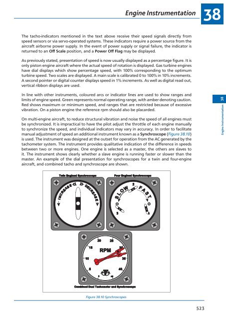
- Page 523 and 524: Engine Instrumentation 38 The engin
- Page 525 and 526: Engine Instrumentation 38 - Engine
- Page 527: Engine Instrumentation 38 The Elect
- Page 531 and 532: Engine Instrumentation 38 The gas t
- Page 533 and 534: Engine Instrumentation 38 Air tempe
- Page 535 and 536: Engine Instrumentation 38 indicates
- Page 537 and 538: Engine Instrumentation 38 Engine In
- Page 539 and 540: Engine Instrumentation 38 The princ
- Page 541 and 542: Engine Instrumentation 38 As well a
- Page 543 and 544: Chapter 39 Electronic Instrumentati
- Page 545 and 546: Electronic Instrumentation 39 Elect
- Page 547 and 548: Electronic Instrumentation 39 Seven
- Page 549 and 550: Electronic Instrumentation 39 Displ
- Page 551 and 552: Electronic Instrumentation 39 In or
- Page 553 and 554: Electronic Instrumentation 39 As fa
- Page 555 and 556: Electronic Instrumentation 39 Failu
- Page 557 and 558: Electronic Instrumentation 39 Elect
- Page 559 and 560: Questions 39 7. The electronic engi
- Page 561 and 562: 10 REVISION QUESTIONS ATPL GROUND T
- Page 563 and 564: Chapter 40 Revision Questions Fligh
- Page 565 and 566: Revision Questions 40 Flight Instru
- Page 567 and 568: Revision Questions 40 14. The verti
- Page 569 and 570: Revision Questions 40 27. V FE is t
- Page 571 and 572: Revision Questions 40 39. The prope
- Page 573 and 574: Revision Questions 40 53. In a righ
- Page 575 and 576: Revision Questions 40 68. If a pito
- Page 577 and 578: Revision Questions 40 82. What is t
- Page 579 and 580:
Revision Questions 40 96. V NE is d
- Page 581 and 582:
Revision Questions 40 109. The sing
- Page 583 and 584:
Revision Questions 40 123. What doe
- Page 585 and 586:
Revision Questions 40 138. When des
- Page 587 and 588:
Revision Questions 40 152. What is
- Page 589 and 590:
Answers 40 Answers to Flight Instru
- Page 591 and 592:
Revision Questions 40 7. A yaw damp
- Page 593 and 594:
Revision Questions 40 21. At the mi
- Page 595 and 596:
Revision Questions 40 33. In an aut
- Page 597 and 598:
Revision Questions 40 44. Regarding
- Page 599 and 600:
Revision Questions 40 56. The autos
- Page 601 and 602:
Revision Questions 40 Warning & Rec
- Page 603 and 604:
Revision Questions 40 13. A stall w
- Page 605 and 606:
Revision Questions 40 25. What corr
- Page 607 and 608:
Answers 40 Answers to Warning & Rec
- Page 609 and 610:
Revision Questions 40 7. If the int
- Page 611 and 612:
Revision Questions 40 19. Total Air
- Page 613 and 614:
Revision Questions 40 30. In a thre
- Page 615 and 616:
Revision Questions 40 43. What does
- Page 617 and 618:
Answers 40 Answers to Engine Instru
- Page 619 and 620:
Revision Questions 40 8. Which of t
- Page 621 and 622:
Revision Questions 40 20. What is u
- Page 623 and 624:
Revision Questions 40 34. An IRS di
- Page 625 and 626:
Revision Questions 40 45. Sound is
- Page 627 and 628:
Revision Questions 40 59. The EADI
- Page 629 and 630:
Answers 40 Explanations to Specimen
- Page 631 and 632:
Answers 40 10. To calculate the rat
- Page 633 and 634:
Answers 40 22. Answer B 23. Answer
- Page 635 and 636:
Answers 40 47. C ± D = M ± V = T
- Page 637 and 638:
Revision Questions 40 Specimen Exam
- Page 639 and 640:
Revision Questions 40 12. Which of
- Page 641 and 642:
Revision Questions 40 22. What erro
- Page 643 and 644:
Revision Questions 40 32. During an
- Page 645 and 646:
Revision Questions 40 42. What are
- Page 647 and 648:
Revision Questions 40 50. EPR is th
- Page 649 and 650:
Revision Questions 40 Revision Ques
- Page 651 and 652:
Chapter 41 Index 645
- Page 653 and 654:
Index 41 Symbols 400 - 330 feet RA
- Page 655 and 656:
Index 41 Carrier Frequency ........
- Page 657 and 658:
Index 41 Electrics and Electronics
- Page 659 and 660:
Index 41 Independent Mode .........
- Page 661 and 662:
Index 41 Off Route Waypoints ......
- Page 663 and 664:
Index 41 Serviceability Checks ....
- Page 665 and 666:
Index 41 Wedge Plate ..............