
Create successful ePaper yourself
Turn your PDF publications into a flip-book with our unique Google optimized e-Paper software.
F D<br />
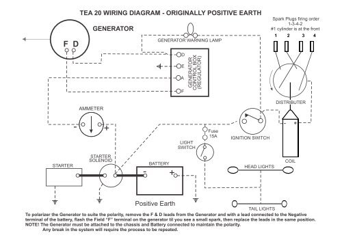
TEA 20 WIRING DIAGRAM - ORIGINALLY POSITIVE EARTH<br />
AMMETER<br />
GENERATOR<br />
GENERATOR WARNING LAMP<br />
D<br />
E<br />
A<br />
F<br />
GENERATOR<br />
CONTROL BOX<br />
(REGULATOR)<br />
Spark Plugs firing order<br />
1-3-4-2<br />
#1 cylinder is at the front<br />
1 2 3 4<br />
DISTRIBUTER<br />
-<br />
+<br />
LIGHT<br />
SWITCH<br />
Fuse<br />
15A<br />
IGNITION SWITCH<br />
- +<br />
STARTER<br />
STARTER<br />
SOLENOID<br />
- BATTERY +<br />
HEAD LIGHTS<br />
COIL<br />
Positive Earth<br />
TAIL LIGHTS<br />
To polarizer the <strong>Generator</strong> to suite the polarity, remove the F & D leads from the <strong>Generator</strong> <strong>and</strong> with a lead connected to the Negative<br />
terminal of the battery, flash the Field “F” terminal on the generator til you see a small spark, then replace the leads in the same position.<br />
NOTE! The <strong>Generator</strong> must be attached to the chassis <strong>and</strong> Battery connected to maintain the polarity.<br />
Any break in the system will require the process to be repeated.
TEA 20 WIRING DIAGRAM - for TRACTORS CONVERTED TO NEGATIVE EARTH<br />
F D<br />
GENERATOR<br />
GENERATOR WARNING LAMP<br />
D<br />
E<br />
A<br />
F<br />
GENERATOR<br />
CONTROL BOX<br />
(REGULATOR)<br />
Spark Plugs firing order<br />
1-3-4-2<br />
#1 cylinder is at the front<br />
1 2 3 4<br />
AMMETER<br />
DISTRIBUTER<br />
+ -<br />
LIGHT<br />
SWITCH<br />
Fuse<br />
15A<br />
IGNITION SWITCH<br />
- +<br />
STARTER<br />
STARTER<br />
SOLENOID<br />
BATTERY<br />
+ -<br />
HEAD LIGHTS<br />
COIL<br />
Negative Earth<br />
TAIL LIGHTS<br />
To polarizer the <strong>Generator</strong> to suite the polarity, remove the F & D leads from the <strong>Generator</strong> <strong>and</strong> with a lead connected to the Positive<br />
terminal of the battery, flash the Field “F” terminal on the generator til you see a small spark, then replace the leads in the same position.<br />
NOTE! The <strong>Generator</strong> must be attached to the chassis <strong>and</strong> Battery connected to maintain the polarity.<br />
Any break in the system will require the process to be repeated.
When <strong>and</strong> How to Polarize a <strong>Generator</strong><br />
Polarization is a procedure which matches the polarity for the generator <strong>and</strong> the voltage regulator by permitting a surge of current to flow<br />
through the generator, correctly polarizing it. Damage to electrical components can occur if polarities do not match.<br />
Ferguson tractors have utilized both positive <strong>and</strong> negative ground systems.<br />
Delco 6V systems have positive ( + ) ground.<br />
Delco 12 V systems have negative ( - ) ground.<br />
Lucas systems for both 6V <strong>and</strong> 12V models have positive ( + ) ground.<br />
Lucas systems converted to electronic distributer with a 12V system have negative ( - ) ground.<br />
Polarization of the generator should take place whenever any of the following events occur:<br />
1. The battery is replaced or disconnected from the tractor<br />
2. The generator is replaced or serviced<br />
3. The regulator is replaced or serviced<br />
If any of these events occurred, do not start the engine until polarization is done.<br />
The polarity of the generator must be set to match that of the voltage regulator.<br />
For positive ground systems: To polarizer the <strong>Generator</strong> to suite the polarity, remove the F & D leads from the <strong>Generator</strong> <strong>and</strong> with a<br />
lead connected to the Negative terminal of the battery, flash the Field “F” terminal on the generator til you see a small blue spark, then<br />
replace the leads in the same position as they were before.<br />
For negative ground systems: To polarizer the <strong>Generator</strong> to suite the polarity, remove the F & D leads from the <strong>Generator</strong> <strong>and</strong> with a<br />
lead connected to the Positive terminal of the battery, flash the Field “F” terminal on the generator til you see a small blue spark, then<br />
replace the leads in the same position as they were before.<br />
NOTE! The <strong>Generator</strong> <strong>and</strong> Battery Earth must be attached to the chassis to maintain the polarity.<br />
Any break in the system (i.e. battery or generator removed or regulator <strong>wiring</strong> disconnected) will require the process<br />
to be repeated.
Ind Bat<br />
TEA 20 WIRING DIAGRAM - NEGATIVE EARTH<br />
ALTERNATOR<br />
ALTERNATOR WARNING LAMP<br />
Spark Plugs firing order<br />
1-3-4-2<br />
#1 cylinder is at the front<br />
1 2 3 4<br />
GENERATOR<br />
CONTROL BOX<br />
(REGULATOR)<br />
REGULATOR<br />
NOT<br />
REQUIRED<br />
AMMETER<br />
DISTRIBUTER<br />
+ -<br />
LIGHT<br />
SWITCH<br />
Fuse<br />
15A<br />
IGNITION SWITCH<br />
- +<br />
STARTER<br />
STARTER<br />
SOLENOID<br />
BATTERY<br />
+ -<br />
HEAD LIGHTS<br />
COIL<br />
Negative Earth<br />
TAIL LIGHTS<br />
The <strong>Alternator</strong> requires no Polarization process
D<br />
F<br />
Ferguson TEA20 Tractor with a <strong>Generator</strong><br />
12V Positive earth system plus Ammeter <strong>wiring</strong> explained<br />
Yellow<br />
May also be grounded<br />
at starter switch<br />
Green<br />
Note! If no Ammeter,<br />
wire directly from<br />
A on Regulator to<br />
the starter switch<br />
as shown<br />
Yellow<br />
Green Strip<br />
-<br />
Black<br />
Ammeter<br />
D<br />
E<br />
A<br />
F<br />
GENERATOR<br />
CONTROL BOX<br />
(REGULATOR)<br />
Yellow<br />
White<br />
Yellow<br />
Green Strip<br />
Charge Indicator<br />
White<br />
Keyed Ignition Switch<br />
ON/OFF<br />
Fuse 15A<br />
Circuit for accessories<br />
if required<br />
Ground return from<br />
accessories, if required.<br />
Terminate on the “-” battery<br />
terminal or any where on<br />
the chassis i.e. the ground<br />
bolt on the starter switch<br />
1 2<br />
+<br />
3 4<br />
DISTRIBUTOR<br />
Firing seq. 1-3-4-2<br />
(Cilinder #1 at front of moter<br />
Red<br />
Black<br />
+ -<br />
LUCAS<br />
COIL<br />
12V<br />
STARTER MOTOR<br />
LUCAS 25079J<br />
Yellow<br />
Green Strip<br />
-<br />
+<br />
12V<br />
Battery<br />
Firing order 1-3-4-2 #1 cylinder is at the front<br />
Negative Earth<br />
Can be grounded to the chassis at<br />
the Oil Filler Casting or the mounting<br />
bolts on the starter motor or one of<br />
the steering housing bolts.<br />
Anywhere will do so long as there is<br />
a good earth connection.<br />
To polarizer the <strong>Generator</strong> to suite the polarity, remove the F & D leads from the <strong>Generator</strong> <strong>and</strong> with a lead connected to the Negative<br />
terminal of the battery, flash the Field “F” terminal on the generator til you see a small spark, then replace the leads in the same position as before.<br />
NOTE! The <strong>Generator</strong> must be attached to the chassis <strong>and</strong> Battery connected to maintain the polarity.<br />
Any break in the system will require the process to be repeated.
Ferguson TEA20 Tractor with a <strong>Generator</strong><br />
12V Negative earth system<br />
Yellow<br />
D<br />
F<br />
Yellow<br />
May also be grounded<br />
at starter switch<br />
Green<br />
Note! If no Ammeter,<br />
wire directly from<br />
A on Regulator to<br />
the starter switch<br />
as shown<br />
Yellow<br />
Green Strip<br />
+<br />
Black<br />
Ammeter<br />
D<br />
E<br />
A<br />
F<br />
GENERATOR<br />
CONTROL BOX<br />
(REGULATOR)<br />
White<br />
Yellow<br />
Green Strip<br />
Charge Indicator<br />
White<br />
Keyed Ignition Switch<br />
ON/OFF<br />
Fuse 15A<br />
Circuit for accessories<br />
if required<br />
Ground return from<br />
accessories, if required.<br />
Terminate on the “-” battery<br />
terminal or any where on<br />
the chassis i.e. the ground<br />
bolt on the starter switch<br />
1 2<br />
-<br />
3 4<br />
DISTRIBUTOR<br />
Firing seq. 1-3-4-2<br />
(Cilinder #1 at front of moter<br />
Red<br />
Black<br />
-<br />
+<br />
LUCAS<br />
COIL<br />
12V<br />
STARTER MOTOR<br />
LUCAS 25079J<br />
Yellow<br />
Green Strip<br />
+<br />
-<br />
12V<br />
Battery<br />
Firing order 1-3-4-2 #1 cylinder is at the front<br />
Negative Earth<br />
Can be grounded to the chassis at<br />
the Oil Filler Casting or the mounting<br />
bolts on the starter motor or one of<br />
the steering housing bolts.<br />
Anywhere will do so long as there is<br />
a good earth connection.<br />
To polarizer the <strong>Generator</strong> to suite the polarity, remove the F & D leads from the <strong>Generator</strong> <strong>and</strong> with a lead connected to the Positive<br />
terminal of the battery, flash the Field “F” terminal on the generator til you see a small spark, then replace the leads in the same position as before.<br />
NOTE! The <strong>Generator</strong> must be attached to the chassis <strong>and</strong> Battery connected to maintain the polarity.<br />
Any break in the system will require the process to be repeated.
This is the colour coding of the harness that I purchased<br />
all going well, this maybe a st<strong>and</strong>ard colour coding used in Australia.<br />
NOTE! The harness did not have the wires in the appropriate place for the ammeter, hence the comment at the Ammeter**<br />
<strong>Generator</strong><br />
Charge light<br />
Regulator<br />
Ignition Switch<br />
Coil<br />
Ammeter<br />
Distributer<br />
“F” small lug green to “F” on regulator<br />
“D” large lug yellow to “D” to charge light then extended to “D” on regulator<br />
white to ignition switch<br />
yellow from “D” on generator then extended to “D” on regulator<br />
“F” green from generator<br />
“A” yellow with green stripe to positive side of starter switch<br />
“E” black to earth<br />
“D” yellow from generator via charge light<br />
white from charge light then to + on coil for negative earth or - on coil for positive earth<br />
yellow with green stripe to positive side of starter switch<br />
white to ignition switch<br />
cut the yellow with a green stripe wire in an appropriate place, connect the end of the cut wire from the<br />
regulator to the + side of the ammeter <strong>and</strong> the other end to the - side of the ammeter (i.e. “A” on regulator<br />
to “+” on ammeter then “-” on ammeter to battery side of starter switch<br />
Note!** you will need to add wire to extend to the ammeter<br />
some distributers have 2 wires 1 red <strong>and</strong> 1 black.<br />
connect the black to “-” on coil <strong>and</strong> red to “+” on coil.<br />
<strong>Alternator</strong><br />
Regulator<br />
Charge light<br />
<strong>Alternator</strong> conversion kit B8810 from Bare-Co<br />
Note! Tractor must be Converted to Negative earth system<br />
disconnect (cut back & tape up) all wires from the generator..........................<br />
}<br />
disconnect (cut back & tape up) all wires from the regulator........................... these wires are now NOT required<br />
disconnect (cut back & tape up) original yellow wire(s) on the charge light.<br />
New Harness connect red wire with large spade terminal to “B+ on alternator, other end to battery “+” or if fitted, ammeter “+”<br />
((another red wire is then required (not supplied) to run from ammeter - to battery +))<br />
connect new yellow wire with small spade terminal to “D+” on alternator <strong>and</strong> terminate on charge light in place of<br />
the original yellow wire(s) Job Done.<br />
Disclaimer: While I have done my best to ensure acsuracy on these eight pages, no responsibility is accepted for errors or omissions of information
Ferguson TEA20 Tractor with an <strong>Alternator</strong><br />
12V Negative earth system<br />
1 2<br />
3 4<br />
<strong>Alternator</strong><br />
DISTRIBUTOR<br />
Firing seq. 1-3-4-2<br />
(Cilinder #1 at front of moter<br />
Bat<br />
New Yellow as provided in <strong>Alternator</strong> Harness<br />
D+<br />
Red<br />
Black<br />
-<br />
+<br />
LUCAS<br />
COIL<br />
12V<br />
Red<br />
+<br />
Note! If no Ammeter,<br />
wire directly from Ammeter<br />
“B” on <strong>Alternator</strong> to<br />
the Positive Battery<br />
Terminal. Otherwise<br />
add a new wire (red)<br />
from the - on the ammeter to<br />
the Positive Battery Terminal<br />
STARTER MOTOR<br />
LUCAS 25079J<br />
D<br />
E<br />
A<br />
F<br />
Red continued<br />
GENERATOR<br />
CONTROL BOX<br />
(REGULATOR)<br />
No Ammeter<br />
see note 1<br />
White<br />
Yellow<br />
Green Stripe<br />
+<br />
-<br />
Charge Indicator<br />
White<br />
12V<br />
Battery<br />
Fuse 15A<br />
Circuit for accessories<br />
if required<br />
Ground return from<br />
accessories, if required.<br />
Terminate on the “-” battery<br />
terminal or any where on<br />
the chassis i.e. the ground<br />
bolt on the starter switch<br />
Keyed Ignition Switch<br />
ON/OFF<br />
Negative Earth<br />
(Some tractors have the<br />
Battery Grounded to the<br />
chassis at the Oil Filler Casting<br />
some to one of the mounting<br />
bolts on the starter motor )<br />
The <strong>Alternator</strong> requies no Polarization process.<br />
Note 1: this wire can also be terminated at the battery “+” terminal<br />
instead of the battery side of the starter switch